1
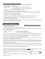
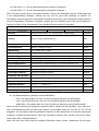
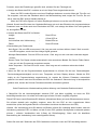
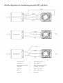
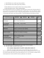
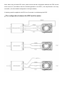
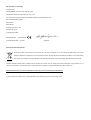
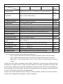
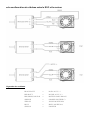
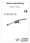
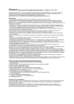
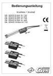
GM-GENIUS RACE 80R BL - ESC für Wettbewerbs und Sport-Autos Bedienungsanleitung Best.-Nr. 7157 Herzlichen Glückwunsch zum Kauf des vielseitigen Reglers für Bürstenlose und Bürstenmotoren von Graupner. Bürstenlose Antriebe bieten eine hohe Leistung und hohen Wirkungsgrad bei geringem Gewicht und kleinen Abmessungen. Eine erfolgreiche Anwendung setzt aber die Einhaltung bestimmter Grundsätze voraus. Lesen Sie bitte vor der Inbetriebnahme diese Bedienungsanleitung aufmerksam durch. Warnhinweise: - Das CE-Zertifikat des Reglers entbindet nicht der Verpflichtung, äußerste Vorsicht zu wahren. - Sollte der Motor einmal nicht wie gewünscht anlaufen oder bei einem Absturz stellen Sie den Senderknüppel sofort auf Motorposition aus, um eine Überlastung des Reglers zu vermeiden. Überprüfen Sie noch mal den richtigen Anschluss des Motors, kürzen Sie eventuell die Kabel und stellen Sie bei Bedarf am Sender eine Zeitverzögerung für die Gasannahme ein, um Timingfehler zu verhindern. - Benutzen Sie nur Motoren von GM-Racing oder Graupner, die für den verwendeten Spannungsbereich vorgesehen sind! - Verwenden Sie nur Hochleistungsakkus von GM-Racing oder Graupner. Akkus mit einem zu hohen Innenwiderstand können zur Zerstörung des Reglers führen! Benutzen Sie auf keinen Fall ein Netzteil für die Stromversorgung! - Lassen Sie Ihr RC-Modell niemals unbeaufsichtigt, solange ein Akku angesteckt ist. Im Falle eines Defektes, könnte dies Feuer am Modell oder seiner Umgebung verursachen. - Der Fahrtenregler oder andere elektronische Komponenten dürfen niemals mit Wasser in Berührung kommen. Der Fahrtenregler ist vor Staub, Schmutz, Feuchtigkeit, Vibration und anderen Fremdteilen zu schützen. - Sie dürfen niemals den Motor mit einem separaten Akku laufen lassen. Dies zerstört den Regler und Motor und führt zum Verlust der Garantie. - Verpolen Sie Ihren Regler nicht. Benutzen Sie verpolsichere Stecksysteme. Vermeiden Sie Kurzschlüsse und blockierende Motoren. - Alle Kabel und Verbindungen sollen gut isoliert sein. Kurzschlüsse können zur Zerstörung Ihres Reglers führen. - Nicht für Kinder unter 14Jahren, kein Spielzeug! - Die Regler sind ausschließlich für den Einsatz in Batterie- bzw. Akkubetriebenen, funkferngesteuerten Modellen vorgesehen, ein anderweitiger Betrieb ist nicht zulässig. Der Gebrauch in einem Modell zur Personenbeförderung ist verboten! - Motoren, Getriebe, Schiffs- oder Luftschrauben sind gefährliche Gegenstände. Halten Sie sich daher niemals neben oder vor dem Gefährdungsbereich des Antriebes auf! - Technische Defekte mechanischer oder elektronischer Teile können zum unverhofften Anlaufen des Motors und herumfliegenden Teilen führen, die erhebliche Verletzungen verursachen können. - Führen Sie immer zuerst einen Reichweitetest und Funktionstest am Boden durch (halten Sie dabei Ihr Modell fest), bevor Ihr Modell zum Einsatz kommt. Wiederholen Sie den Test bei laufendem Motor und mit kurzen Gasstößen. - Es dürfen keinerlei Veränderungen am Regler durchgeführt werden, es sei denn, diese sind in der Anleitung beschrieben. - Haftungsausschluss: Sowohl die Einhaltung der Montage- und Bedienungsanleitung, als auch die Bedingungen und Methoden bei Installation, Betrieb, Verwendung und Wartung des Fahrtenreglers können von der Fa. Graupner nicht überwacht werden. Daher übernimmt die Fa. Graupner keinerlei Haftung für Verluste, Schäden oder Kosten, die sich aus fehlerhafter Verwendung und Betrieb ergeben, oder in irgendeiner Weise damit zusammenhängen. - Es dürfen nur von uns empfohlene Komponenten und Zubehörteile verwendet werden. Verwenden Sie nur zueinander passende, Original GRAUPNER - Steckverbindungen und Zubehörteile. - Vergewissern Sie sich vor jeder Inbetriebnahme bevor Sie den Fahrtenregler einstecken, dass: Ihr Sender als einziger auf der Frequenz Ihres Empfängers sendet und Ihr Sender eingeschaltet ist und der Gashebel auf der Position STOP steht. Merkmale des ESC (elektronischer Fahrtregler). 1. Voll proportionaler Vorwärtsgang mit Bremse EIN/AUS und Rückwärtsgang 2. Sanfte Reaktion auf Gasänderungen 3. Motortyp wählbar (Sensorless BLDC, Sensored BLDC, Brushed DC) (Bürstenloser Motor ohne / mit Sensor, Bürstenmotor) 4. Verwendbar mit Li-Po, Li-Fe und NiMH (NiCd) - Akkus 5. Einstellbare Start-Stromstärke und Strombegrenzungsfunktion 6. Verschiedene Bremssysteme (Speed Mixing – Bremse (geschwindigkeitsabhängige Bremse), ABS Bremse, Auto / Minimum / Maximum Bremse) 7. Nur vorwärts / Vor- und Rückwärtsfahrt wählbar 8. Einfaches Einstellen und Auslesen von Fahrt-Informationen mit Hilfe der Programmier-Karte. 9. Mit Bürstenkollektor (2 kHz), mit Sensor (2 kHz Schaltfrequenz), ohne Sensor (32KHz) 10. Schutzfunktion gegen Überhitzung *** Wenn der Sensorlose Betrieb gewählt wird, muss es sich um einen Motor ohne Sensoren handeln oder die Sensoren dürfen nicht eingesteckt sein. Einstellen der ESC-Senderwege ESC-Sounds : Do, Re, Mi, Fa, So, La, Ti Do. 1. Schalten Sie den Sender ein. 2. Schließen Sie den Akku an und schalten Sie den ESC ein. 3. Wenn alle Verbindungskabel richtig angeschlossen sind, muss der Motor je nach Gashebel-Stellung folgende Pieptöne ausgeben: Do, Re ~~ Do, Re, Mi : bei Neutralstellung des Gashebels Do, Re ~~ : bei jeder anderen Stellung des Gashebels 4. Wenn Sie die Einstell-Taste länger als 1 Sekunde drücken, muss die grüne LED blinken. Lassen Sie jetzt die Taste los; nun muss die grüne LED leuchten und der Motor muss mit folgenden Pieptönen: So, So, La, La, So, So anzeigen, dass die Neutralstellung gespeichert ist. 5. Bringen Sie den Gashebel in die Vollgas-Stellung. Nun muss die rote LED leuchten und damit anzeigen, dass die Vollgasstellung gespeichert ist. 6. Bringen Sie den Gashebel nach hinten in die Vollbremsungs- oder Volle Rückwärtsfahrt-Stellung, nun müssen die rote und die grüne LED leuchten und damit anzeigen, dass die Stellung Vollbremsung oder Volle Rückwärtsfahrt gespeichert ist. 7. Bringen Sie den Gashebel in die Neutralstellung. Nun müssen die rote und die grüne LED im Wechsel leuchten und der Motor muss die Töne So, Fa, Mi, Re, Do ausgeben. Dann muss die grüne LED leuchten und damit anzeigen, dass der ESC jetzt betriebsbereit ist. Hinweis 1: Dieses anfängliche Speichern der Gasstellungen wird nur dann wieder erforderlich, wenn Sie einen anderen Sender benützen, oder wenn sich die Einstellungen verändert haben Hinweis 2: Nach dem Einschalten des ESC kann die Gashebelstellung nur eingerichtet werden, bevor der Motor läuft. Hinweis 3: Wenn sich die Vollgasstellung nicht speichern lässt, verändern Sie bitte die Stellung Rückwärts / Normal. Einstellungen im Benutzer-Modus 1. Schalten Sie den Sender ein. 2. Schließen Sie den Akku an und schalten Sie den ESC ein. 3. Wenn alle Verbindungskabel richtig angeschlossen sind, muss der Motor je nach Stellung des Gashebels folgende Pieptöne ausgeben: Do, Re ~~ Do, Re, Mi : bei Neutralstellung des Gashebels Do, Re ~~ : bei jeder anderen Stellung des Gashebels 4. Wenn Sie die Einstell-Taste länger als 1 Sekunde drücken, muss die grüne LED 2 Sek. lang blinken, dann muss die rote LED sofort anfangen zu blinken. Lassen Sie jetzt die Taste los; nun muss der Motor die Pieptöne: Mi, Re, Do, Re, Mi ausgeben, und die rote LED muss mit einer Blinkfolge zeigen, dass der ESC sich jetzt im Setup des Benutzer- Modus ( user mode setup ) befindet. Bei einmaligem längerem Blinken geht der Motor in das Menu Einstellen des Motortyps über. 18 verschiedene Programm-Merkmale können in den Regler eingegeben werden, wie im Folgenden gezeigt. Wenn im Programmier-Modus die Setup-Taste kurz gedrückt und wieder losgelassen wird, verlässt der ESC den Programmiermodus und ist betriebsbereit. 1. Motortyp wählen 2. Akku-Typ 3. Unterspannungsabregelung 4. Leistungskurve 5. Motortiming 6. Beschleunigung 7. Startleistung 8. Startstrombegrenzung 9. Strombegrenzung 10. Rückwärtsfunktion 11. Rückwärtsverzögerung 12. Maximale Rückwärtsfahrt 13. Neutralpunktbreite 14. Geschwindigkeitsabhängige Bremse 15. A.B.S.-Bremse 16. Automatikbremse 17. Minimale Bremse 18. Maximale Bremse 19. Werkseinstellung Immer wenn Sie den Gashebel von Neutral auf Vollgas und zurück bewegen (Gas zu (Neutral) > ganz auf (Vollgas) > zu (Neutral) ist ein Steuer/Programmschritt), wird das nächste Programm aufgerufen. Die rote LED blinkt dabei nach folgendem Schema: 1) Rote LED blinkt einmal ( Motortyp wählen ist aktiviert ) 2) Rote LED blinkt zweimal (Akku-Typ wählen ist aktiviert ) …… 18) Rote LED blinkt 18 mal ( Maximale Bremse einstellen ist aktiviert ) 19) Rote LED blinkt 19 mal ( Werkseinstellung einstellen ist aktiviert ) Wenn Sie nach Anwahl einer zu programmierenden Funktion den Gashebel mehr als 4 Sekunden lang in der Vollgasstellung festhalten, müssen die rote und die grüne LED anfangen zu blinken, um anzuzeigen, dass Sie jetzt einen eingestellten Parameter durch einen neuen Parameter ersetzen können. Um den eingestellten Parameter zu ändern, bringen Sie den Gashebel erst in die (untere) MinimumStellung und dann in die Vollgasstellung. Der gewählte Parameter wird so angezeigt: Ohne Sensor Mit Sensor Kollektortyp Voreingest. 1 Motortyp Bürlstenlos ohne Sensor (1) / mit Sensor (2) / Kollektortyp(3) Mit Sensor 2 Akkutyp LiPo(1) / LiFe(2) / NiMh (NiCd) (3) LiMh 3 Unterspg.-Abregelung Auto(1) / 3,0V(2) ~ 5,5V (0,1V Schritte) Auto 4 Leistungskurve Sanft (1) / Linear(2) / Hart(3) Linear 5 Motortiming 0`(1) ~ 25`(6) / 0(1) ~ 10(6) 25’ / 10 6 Beschleunigung Sehr niedrig(1) / Niedrig / Normal / Hoch / sehr Hoch(5) Sehr Hoch 7 Startleistung 8 Startstrombegrenzung 9 Strombegrenzung Sehr niedrig(1) / Niedrig / Normal / Hoch / sehr Hoch(5) Sehr Hoch. AUS, 10% (2) ~ 100%(11) AUS, 10% (2) ~ 100%(11) AUS AUS 10 Rückwärtsfunktion Eine Richtung (1) / Zwei Richtungen 1 (2) / Zwei Richtungen 2 (3) Zwei R.(2) 11 Reverse Delay 0.2s(1) / 0.5s / 0.8s / 1.3s / 1.8s / 2.5s (6) 2.5s 12 Max. Rückwärtsfahrt 20% (1) ~ 100%(9) 60% 13 Neutralpunktbreite Schmal(1) / Normal(2) / Breit(3) Normal 14 Geschw.-abh. Bremse 0%(1) ~ 100%(11) 0% 15 A.B.S.-Bremse Aus (1) / Sehr schwach / Schwach / Normal / Stark / Sehr stark (6) Aus 16 Automatikbremse 0 % (1) ~ 100% (11) 0% 17 Minimale Bremse 0 % (1) ~ 100% (11) 30% 18 Maximale Bremse 0 % (1) 19 Werkseinstellung Alle Parameter werden auf Auslieferungszustand gesetzt (2) ~ 100% (11) 100% z Die Zahlen in den Klammern oben zeigen, wie oft die LED blinkt. z Die Abschaltspannung beträgt im Automatik-Modus: - LiPo : Der höhere Wert aus 5.5V und 66% der Spannung nach dem Einschalten. - LiFe : Der höhere Wert aus 5.0V und 67% der Spannung nach dem Einschalten. - NiMh/ NiCd : Der höhere Wert aus 4.0V und 66% der Spannung nach dem Einschalten. Wenn Sie den Parameter wie gewünscht eingestellt haben, hallten Sie den Gashebel über mehr als 4 Sek. in Neutralstellung. Die rote LED muss blinken und der Motor muss die Töne Mi, Re, Do, Re, Mi ausgeben, um anzuzeigen, dass der gewählte Parameter im ESC gespeichert ist und dass jetzt andere Parameter verändert werden können. Wenn alle Parameter geändert sind, drücken Sie kurz die Taste. Dann ist der ESC im Standby-Modus. Wenn Sie jetzt noch einen anderen Programm-Parameter ändern wollen, wiederholen Sie die obige Prozedur; wenn alle Einstellungen getroffen sind, schalten Sie den Fahrtregler ab. • Anzeige des Status des ESC, nachdem er mit der Setup-Taste eingeschaltet wurde: - Wenn der ESC korrekte Signale von einem Empfänger bekommt, muss der Motor die Töne Do und Re ausgeben, und wenn der Gashebel dabei in der Neutralstellung steht, zeigen die Töne Do, Re und Mi an, dass der ESC jetzt im Standby-Modus ist. - Wenn der ESC keine Signale von einem Empfänger bekommt, muss die rote LED blinken Hinweis: Sowohl das Einrichten der Gashebel-Stellungen als auch das Einstellen der programmierbaren Parameter kann nur direkt nach dem Einschalten des ESC, und solange der Motor noch nicht gelaufen ist, durchgeführt werden. • Anzeige des Status des ESC im Betrieb: Vollgas : Rote LED an Neutral : Grüne LED an Voll rückwärts oder Vollbremsung : Beide LEDs an Fehler : Rote LED blinkt • Beschreibung der Fehlercodes: Kein Signal : Die rote LED muss zuerst 1 Sek. lang aus sein und dann blinken. Nach 5 Sek. muss die rote LED ausgehen; es wird auf das richtige Signal gewartet. Niedriger Batteriestand : Die rote LED muss zuerst 1 Sek. lang aus sein und dann mehrmals doppelt blinken. Sensor Fehler: Der Regler schaltet automatisch in den sensorlosen Betrieb. Der Sensor Fehler Status kann nur mit dem Programmer ausgelesen werden. Hohe Temperatur : Die rote LED muss zuerst 1 Sek. lang aus sein und dann mehrmals vierfach blinken. • Wenn der ESC an die Programmierkarte angeschlossen ist, können Sie die max. Geschwindigkeit, Durchschnittsgeschwindigkeit und die max. Temperatur auf dem Display ablesen. Sobald der ESC richtig an die Programmierkarte angeschlossen ist, werden die früheren Fahrtdaten automatisch gelöscht. Und wenn nach dem Einschalten des ESC der Gashebel 5 Sekunden lang in Neutralposition gehalten wird, werden die früheren Fahrdaten ebenfalls automatisch gelöscht. Beim Einstellen der Werkseinstellung bleiben Motortyp und Gashebel-Position erhalten! • Überprüfen Sie die Verbindungskabel zwischen ESC und Motor sorgfältig, da sonst der ESC beschädigt werden kann. Vor allem bei Änderungen müssen Sie sehr sorgfältig vorgehen. Dieser ESC kann sowohl Brushless-DC-Motoren (bürstenloser Motor) wie auch Bürstenmotoren steuern. Sie müssen deshalb sehr sorgfältig vorgehen, wenn Sie den ESC an den vorgesehenen Motor anschließen (siehe die folgende Skizze zum korrekten Anschluss des Motors an den ESC). Hinweis : Bei Verwendung eines DC-Motors mit Bürsten müssen Sie unbedingt darauf achten, dass die Verkabelung zwischen ESC und Motor und die für den ESC gewählte Konfiguration zueinander passen müssen ( einfache Vorwärtsfahrt oder 2-Gang mit Rückwärtsgang). Siehe auch die detaillierte Beschreibung der Verkabelung in der nachfolgenden Skizze). Sollten Sie mehr als 5 Sekunden am ESC Lötarbeiten vornehmen, kann der ESC beschädigt werden. • Die Konfiguration der Verkabelung zwischen ESC und Motor. BLACK BATT = SCHWARZ: AKKU (-) RED BATT = ROT: AKKU (+) BRUSHLESS MOTOR = BÜRSTENLOSER MOTOR ORENGE = ORANGE (MOTOR C) YELLOW = GELB (MOTOR B) BLUE = BLAU (MOTOR A) SENSOR = SENSOR BLACK BATT = SCHWARZ: AKKU (-) RED BATT = ROT: AKKU (+) BRUSHED MOTOR = BÜRSTENMOTOR ORENGE = ORANGE: + (MOTOR) YELLOW = GELB: + (MOTOR) BLUE = BLAU: – (MOTOR) BLACK BATT = SCHWARZ: AKKU (-) RED BATT = ROT: AKKU (+), + (MOTOR) BRUSHED MOTOR = BÜRSTENMOTOR ORENGE = ORANGE: – (MOTOR) YELLOW = GELB: – (MOTOR) BLUE = BLAU: – (MOTOR) EG-Konformitätserklärung: Für die folgende bezeichneten Erzeugnisse GM-GENIUS RACE 40R Best.-Nr. 7154 GM-GENIUS RACE 80R Best.-Nr. 7157 PROGRAMMIERGERÄT für GM-GENIUS RACE 40R, 80R Best.-Nr. 7152 wird hiermit bestätigt, dass es den wesentlichen Schutzanforderungen entspricht, die in der Richtlinie des Rates zur Angleichung der Rechtsvorschriften der Mitgliedstaaten über die elektromagnetische Verträglichkeit 2004/108/EC festgelegt sind. Zur Beurteilung des Erzeugnisses wurden folgende Normen herangezogen: EN 61000-6-1 EN 61000-6-3 Diese Erklärung wird verantwortlich für den Hersteller/Importeur Graupner GmbH & Co. KG Henriettenstr. 94-96 73230 Kirchheim/Teck abgegeben durch den Geschäftsführer Hans Graupner 73230 Kirchheim/Teck, den 05.03.09 Unterschrift Hinweise zum Umweltschutz Das Symbol auf dem Produkt, der Gebrauchsanleitung oder der Verpackung weist darauf hin, dass dieses Produkt am Ende seiner Lebensdauer nicht über den normalen Haushaltsabfall entsorgt werden darf. Es muss an einem Sammelpunkt für das Recycling von elektrischen und elektronischen Geräten abgegeben werden. Die Werkstoffe sind gemäß ihrer Kennzeichnung wieder verwertbar. Mit der Wiederverwendung, der stofflichen Verwertung oder anderen Formen der Verwertung von Altgeräten leisten Sie einen wichtigen Beitrag zum Umweltschutz. Bitte erkundigen Sie sich bei der Gemeindeverwaltung die zuständige Entsorgungsstelle. Order-No. 7157 GM-GENIUS RACE 80R COMPETIION AND PRO CAR BL ESC instruction manuals Congratulations for buying this state of the art brushless and brushed speed controller. It is adapted for use with high efficient and powerful brushless motors. Important notice: Please read this manual carefully before using your controller. Only then can you have full profit of the potential of your controller, and avoid mistakes. Warnings: - The controller's CE certificate doesn't unbind users from their obligation to use ultimate caution - Should the motor refuse to start up, or after a crash, then you should immediately set the transmitter's control stick to the OFF position to avoid any overload to the controller. - Use only motors delivered by GM-Racing or Graupner which are designed for the intended range of voltages! - Use only high performance batteries by Graupner or GM-Racing. Using batteries with an increased internal resistance may lead to the destruction of the controller! Do never use a power supply. - Never leave your transmitter unattended when a battery is connected. In case of a deficiency this may cause an outbreak of fire on the model or its environment. - Neither the controller nor any other electronic components should ever come in touch with water. Protect the controller against dust, dirt, humidity, vibrations, or other dangerous elements (with the - Never run the motor on a separate battery. This will exception of water-sealed controllers). destroy the controller or the motor, and leads to the loss of our warranty. - Never mix up polarities. Use plug systems which offer protection against wrong polarity. Avoid short-circuiting and blocking the motors. - All cables and connectors should have good insulation. Short-circuits may lead to the destruction of your motor. - This product isn't designed for use by children under the age of 14, it isn't a toy! - Graupner-controllers are designed for use in battery-driven, radio-controlled models only, any other use is not permissible. Using this device on a passenger-carrying model is forbidden! - Motors, gears or gearboxes, and propellers are dangerous objects. Never keep next to or in front of the danger area of the drive! - Technical defects or failures of mechanical or electronic parts may lead to an unexpected start-up of the motor, with parts of it flying off, maybe causing severe injuries. - Always check the service range of transmission of your model first thing while it's still on the ground (hold the model tightly!). Try again with motor on and also with fast changes of the throttle stick. - Don't make any changes on the structure and design of your controller unless they are described in the manual! - Limited warranty: Graupner Ltd cannot survey the proper application of the mounting and using regulations, nor the working methods and conditions during the installation, use, operation, and servicing of the controller. Therefore Graupner Ltd cannot take on any liability for any loss, damage, or costs resulting from an incorrect use or operation of the product, or connected in any way with incorrect use or operation. - Only those components and accessory parts which have been recommended by us may be used. Use only genuine and matching Graupner connectors and accessory parts. - Make sure whenever you start connecting and operating the controller, that: - your transmitter is the only one working on that frequency, - is switched on, - and has the throttle set to position “STOP”. - Use only high-quality batteries by Graupner or GM-Racing. Cheap or old batteries with a high internal performance or even to the destruction of the controller. resistance may lead to poor ESC features. 1. Fully proportional forward with on/off brake and reverse 2. Smooth throttle response 3. Selectable Motor type (Sensorless BLDC, Sensored BLDC, Brushed DC) 4. Li-Po, Li-Fe, NiMH(NiCd) battery compatible 5. Selectable Start Current & Current Limit Function 6. Various Brake System (Speed Mixing Brake, ABS Brake, Auto / Minimum / Maximum Brake) 7. Selectable One Way / Two Way 8. Easy setting and providing traveling information when using the program card. 9. Brushed (2 kHz) Sensored (2 kHz switching frequency), Sensorless (32KHz) 10. Thermal protection Function *** when sensorless mode is used, sensorless motor must be used. ESC Stick Position setup ESC sound : Do, Re, Mi, Fa, So, La, Ti Do. 1. Turn on the transmitter. 2. Connect the power battery, and switch on the ESC. 3. If all connections are correctly completed, the motor should beep depending on the throttle stick location. Do, Re ~~ Do, Re, Mi : If the stick is at the neutral position, Do, Re ~~ : If the stick is at other position instead of neutral position. 4. If you press and hold the setup button for over 1second, the Green LED should flash. At this time, detach your hand from the button, then the Green LED should be ON and the motor should beep (So, So, La, La, So, So sound) to indicate that the neutral position has been set. 5. Move the throttle stick to the full power position, then the red LED should be ON to indicate that the full power position has been set. 6. Move back the throttle stick to the full reverse or full brake position, then the red and Green LEDs should be ON to indicate that the full reverse or full brake position has been set. 7. Move the throttle stick to the neutral position, then the red and Green LEDs should flash alternatively, and the motor should beep (So, Fa, Mi, Re, Do sound ), then the Green LED should be ON to indicate that the ESC is now ready to be used. Note 1: It is ONLY necessary to make this initial throttle setup again if you are using a different transmitter or the settings have been changed. Note 2: After switching on the ESC, the stick position setup COULD be done ONLY before a motor turns. Note 3: If full power position setting can not be done, pls change the Throttle reverse / Normal. User Mode Setup 1. Turn on the transmitter. 2. Connect the power battery, and switch on the ESC. 3. If all connections are correctly completed, the motor should beep depending on the throttle stick location. Do, Re ~~ Do, Re, Mi : If the stick is at the neutral position, Do, Re ~~ : If the stick is at other position instead of neutral position. 4. If you press and hold the setup button for over 1 second, the Green LED should flash for 2 seconds then the red LED should immediately flash. At this time, detach your hand from the button, the motor should beep (Mi, Re, Do, Re, Mi sound), the red LED should flash once constantly to indicate that the ESC is now in the User mode setting. Flashing repeatedly once enters the Motor type setting. 18 different program features can be set in this controllers as below. In the programmable mode, if the setup button is shortly pressed and detached, it comes out of the programmable mode, the ESC is ready to be used. 1. Select Motor Type 2. Battery Type 3. Cut Off Voltage 4. Power Curve 5. Advance Timing 6. Acceleration 7. Start Power 8. Start Current Limit Function 9. Current Limit Function 10. Reverse Function 11. Reverse Delay 12. Max Reverse Amount 13. Neutral Width 14. Speed Mixing Brake 15. ABS Brake Function 16. Auto Brake Amount 17. Minimum Brake Amount 18. Maximum Brake Amount 19. Factory Setting Every time the throttle stick is moved from the closed position to the full power position and again to the closed position (closed > full power > closed is one cycle ) the program will change. The Red LED will flash in accordance with the features as follows 1) Red LED flashes once ( Motor type setting available ) 2) Red LED flashes twice ( Battery type setting available ) …… 18) Red LED flashes 18 times (Maximum Brake Amount setting available ) 19) Red LED flashes 19 times ( Factory setting available ) At the selected program function to be changed, if the throttle stick is stayed at the full power position for over 4 seconds, the red and green LED should flash to indicate that you can now change an existing parameter to a new parameter. In order to change the existing parameter, move the stick to the minimum or lower position then again to the full power position. The selected parameter will indicate as follows. Sensorless Sensored Brushed Defalut 1 Motor Type Brushless Sensorless(1) / Brushless Sensored(2) / Brushed(3) Sensored 2 Battery Type LiPo(1) / LiFe(2) / NiMh (NiCd) (3) LiMh 3 Cut Off Voltage Auto(1) / 3.0V(2) ~ 5.5V(0.1V Step) Auto 4 Power Curve Soft (1) / Linear(2) / Hard(3) Linear 5Advance Timing 0`(1) ~ 25`(6) / 0(1) ~ 10(6) 25’ / 10 6 Acceleration Lowest(1) / Low / Normal / High / Highest(5) Highest 7 Start Power Lowest(1) / Low / Normal / High / Highest(5) Highest 8 Start Current Limit Off(1), 10% (2) ~ 100% (11) Off 9 Current Limit Off(1), 11% (2) ~ 100% (11) Off 10 Reverse Function One Way(1) / Two Way1(2) / Two Way2(3) Two Way 2 11 Reverse Delay 0.2s(1) / 0.5s / 0.8s / 1.3s / 1.8s / 2.5s (6) 2.5s 12 M-Reverse Amount 20%(1) ~ 100% (9) 60% 13 Neutral Width Narrow(1) / Normal(2) / Wide(3) Normal 14 Speed Mixing Brake 0%(1) ~ 100%(11) 0% 15 A.B.S Brake Off(1) / Weakest / Weak / Normal / Strong / Strongest(6) Off 16 Auto Brk Amount 0 % (1) ~ 100% (11) 0% 17 Min Brake Amount 0 % (1) ~ 100% (11) 30% 18 Max Brake Amount 0 % (1) ~ 100% (11) 19 Factory Setting All parameters to be initialized as factory default values (2) 100% z The inside number of the brackets above is the number of the LED flashing. z The cutoff voltage in automatic mode is as like: - LiPo : the higher voltage between 5.5V and 66% voltage when the switch is on - LiFe : the higher voltage between 5.0V and 67% voltage when the switch is on. - NiMh/ NiCd : the higher voltage between 4.0V and 50%voltage when the switch is on. After you select your wanted parameter, stay the throttle stick at the neutral position for over 4 seconds, the red LED should flash and the motor should beep (Mi, Re, Do, Re, Mi sound) to indicate that the selected parameter is stored at the ESC and other parameters can be selected. After changing all parameters, if the button is shortly pressed, the ESC is now in standby mode. At this stage, if you want to change another program parameter, repeat the procedure above, or if all settings are complicated, turn off the speed controller. • The ESC status when the ESC is powered on through by the setup button. If the ESC receives correct signals from a receiver, the motor should beep ( Do and Re sound ), and if the throttle stick is at the neutral position at this time, the motor should beep ( Do, Re, and Mi sound ) to indicate the ESC is now in the standby mode. If the ESC does not receive any signals from the receiver, the red LED should flash. Note) Both stick position setting and programmable parameter setting can be ONLY proceeded through by the setup button right after the ESC is turned ONLY before a motor turns. • The LED status during operation. Full Throttle : Red LED on Neutral : Green LED on Full Reverse or Full Brake : Both LED on Error : Red LED flashes • Error description No Signal : The red LED should be off for 1 second then flash. After 5 seconds, the red LED should be OFF then waiting for the proper signal. Low Battery : The red LED should be off for 1 second then double flashes repeatedly. Sensor Error : it is automatically converted to sensorless mode, and you can check the error status ONLY in the programmer. High Temperature : The red LED should be off for 1 second then 4times- flashes repeatedly. • Under the ESC connected to the programmer, max speed, average speed, max temperature, and max currents can be seen on the screen of the programmer. Once the ESC is correctly connected with the programmer, the previous traveling data is automatically removed. And, the after switching on the ESC, if the throttle stick stays at the neutral position for over 5 seconds, the previous traveling data is also automatically removed. When doing factory setting, the motor type and stick position should stay as they are. • Please make sure the configuration between the ESC and the motor. Otherwise, it can damage the ESC. You do need great care, especially when change This ESC can handle both brushless DC motor and brushed DC motor, therefore, you do need great care when connecting the ESC with a motor to be used. (see the figure below for the configuration between the ESC and a motor ) correct Note: when using a brushed DC motor, please ensure that the configuration between the ESC and the motor must be in accordance with the selected application in the ESC ( one way-forward or two wayreversible ). See the detailed configuration in the figure below) If soldering would be applied to the ESC over 5 seconds, it could damage the ESC. • The configuration between the ESC and the motor. EG declaration of conformity for the products PROGRAMMER for #7154, 7157 Order-No. 7230 GM-GENIUS RACE 40R, 80R Order.-No. 7154, 7157 We confirm that the electromagnetic compatibility directives (2004/108/CE) are met. Harmonized standards applied: EN 61000-6-1 EN 61000-6-3 Graupner GmbH & Co. KG Henriettenstr. 94-96 73230 Kirchheim/Teck Managing Director Hans Graupner 73230 Kirchheim/Teck, 05.03.09 Signature Environmental Protection Notes When this product comes to the end of its useful life, you must not dispose of it in the ordinary domestic waste. The correct method of disposal is to take it to your local collection point for recycling electrical and electronic equipment. The symbol shown here, which may be found on the product itself, in the operating instructions or on the packaging, indicates that this is the case. Individual markings indicate which materials can be recycled and re-used. You can make an important contribution to the protection of our common environment by re-using the product, recycling the basic materials or recycling redundant equipment in other ways. Remove batteries from your device and dispose of them at your local collection point for batteries. If you don’t know the location of your nearest disposal centre, please enquire at your local council office. Instructions d’utilisation pour le ESC GM-GENIUS RACE 80R BL pour les voitures R/C de sport et de compétition. Réf.-N°. 7157 Félicitations pour votre acquisition d’un régulateur Graupner pour les moteurs Brushless/brushed. Les propulsions avec un moteur Brushless offrent une très grande puissance et un haut rendement pour un faible poids et de petites dimensions. Veuillez lire attentivement ces instructions d’utilisation avant la mise en service. Avertissements : - Le certificat CE du régulateur ne dispense pas de prendre des précautions d’utilisation. - Si le moteur ne démarre pas comme souhaité ou après un crash, ramenez immédiatement le manche des gaz sur la position moteur coupé pour éviter une surcharge au régulateur. Vérifiez à nouveau le raccordement correct du moteur, raccourcissez éventuellement les fils d’alimentation et réglez au besoin un temps de retardement de la mise des gaz dans l’émetteur pour éviter une erreur de calage. - Utilisez uniquement des moteurs de la marque GM-Racing ou Graupner pour lesquels la plage des tensions utilisées est prévue ! - Utilisez uniquement les accus de haute puissance GM-Racing ou Graupner. Les accus avec une résistance trop élevée peuvent conduire à la destruction du régulateur ! N’utilisez en aucun cas un transformateur de courant secteur pour l’alimentation ! - Ne laissez jamais votre modèle R/C sans surveillance tant qu’un accu de propulsion est connecté. Dans le cas d’une défectuosité, le modèle peut prendre feu et le communiquer à son environnement. - Les régulateurs ou les autres éléments électroniques ne doivent jamais venir en contact avec l’eau. La régulateur devra être protégé de la poussière, des salissures, de l’humidité, des vibrations et d’autres corps étrangers. - Ne faites jamais tourner le moteur avec un accu séparé. Ceci détruira le régulateur et le moteur et conduira à la perte du bénéfice de la garantie. - N’inversez jamais les polarités du régulateur ; utilisez un système de connecteurs avec sécurité contre les inversions de polarité .Evites les court-circuits et les blocages du moteur. - Tous les fils et les raccordements devront être bien isolés ; un court-circuit pourra détruire le régulateur - Cet appareil ne convient pas aux enfants en dessous de 14 ans, ce n’est pas un jouet ! - Le régulateur est exclusivement prévu pour l’équipement des modèles radiocommandés avec une alimentation par des accus. toute autre utilisation n’est pas admissible ! - Les moteurs, les réducteurs, les hélices marines ou aériennes sont des objets dangereux. Pour cette raison, ne vous tenez jamais à côté ou devant la zone dangereuse des propulsions ! - Une défectuosité mécanique ou électrique inopinée au démarrage du moteur peut provoquer la projection de pièces et causer de sérieuses blessures. - Effectuez toujours d’abord un essai de porté et des fonctions au sol avant de faire voler votre modèle (en le maintenant fermement !). Répétez ces essais avec le moteur en marche, avec de courts passages à plein gaz. - Aucunes modifications ne devront être apportées sur le régulateur, mises à part celles décrites dans ces instructions. - Exclusion de responsabilité : Le respect des instructions de montage et d’utilisation, aussi bien que les conditions et les méthodes d’installation, d’utilisation et d’entretien ne peuvent pas être surveillées par la Firme Graupner. Pour cette raison, la Firme Graupner décline toute responsabilité pour les pertes, les dégâts ou les coûts survenus à la suite d’une mauvaise utilisation, ou sa participation d’une façon quelconque aux dédommagements. - Il conviendra d’utiliser uniquement les composants et les accessoires que nous conseillons. Utilisez uniquement des connecteurs et des accessoires d’origine GRAUPNER adaptés entreeux . - Avant de connecter votre régulateur, assurez-vous que votre émetteur est le seul à émettre sur la fréquence que vous utilisez et avant de le mettre en contact, que le manche des gaz est sur la position STOP. Particularités du ESC (Régulateur de vitesse électronique) : 1. Passage en marche avant totalement proportionnel avec frein CONTACT/COUPE et passage en marche arrière. 2. Réaction souple aux changements des gaz. 3. Type de moteur sélectionnable (Sans palpeur BLDC, avec palpeur BLDC, Brushed DC) (Moteurs sans balais avec/sans palpeur, moteurs avec balais) 4. Utilisable avec accus Li-Po, Li-Fe et NiMH (NiCd) 5. Fonctions force de courant au départ et limitation en courant réglables 6. Différents systèmes de frein (Mixage Speed-Frein (Freinage dépendant de la vitesse), freinage ABS, freinage Auto / Minimum / Maximum). 7. Seulement Marche avant / Marches avant et arrière sélectionnables. 8. Réglages et lecture simples des informations de marche à l’aide de la carte de programmation. 9. Avec collecteur à balais (2 kHz), avec palpeur (2 kHz de fréquence de commutation), sans palpeur (32KHz). 10. Fonction de protection contre les surchauffes. ***Si le mode sensorless est utilisé, le moteur sensorless ou le moteur doit être utilisé sans cordon sensor. Réglage de la course ESC dans l’émetteur Sons ESC : Do, Ré, Mi, Fa, Sol, La, Si, Do. 1. Mettez l’aémetteur en contact. 2. Reliez l’accu et commlutez le ESC. 3. Lorsque tous les cordons de liaison sont correctement connectés, le moteur soit émettre les sons suivants, selon la position du manche des gaz : Do, Ré ~~ Do, Ré, Mi : avec la position neutre du manche des gaz Do, Ré ~~ : avec chaque autre position du manche des gaz 4. Lorsque la touche de réglage est pressée durant plus de 1 seconde, le LED vert doit clignoter. Relâchez maintenant la touche, le LED vert doit alors s’allumer en permanence et le moteur doit émettre les sons suivants : Sol, Sol, La, La, Sol, Sol indiquant que la position neutre est mémorisée. 5. Placer le manche des gaz sur la position plein gaz. Le LED rouge doit maintenant s’allumer en indiquant ainsi que la position plein gaz est mémorisée. 6. Tirez le manche des gaz en arrière sur la position plein freinage ou pleine marche arrière, les LED vert et rouge doivent maintenant s’allumer en indiquant ainsi que la position plein freinage ou pleine marche arrière est mémorisée. 7. Placez le manche des gaz sur la position neutre. Les LED vert et rouge doivent maintenant s’allumer en alternance et le moteur doit émettre les sons Sol, Fa, Mi, Ré, Do., le LED vert doit ensuite s’allumer et indiquer ainsi que le ESC est maintenant prêt au service. Note 1 : Cette mémorisation initiale des positions de gaz sera ensuite seulement à nouveau nécessaire lorsque vous utiliserez un autre émetteur, ou lorsque vous aurez changé les réglages. Note 2 : Après la mise en contact du ESC, la position du manche des gaz pourra seulement être disposée avant que le moteur tourne. Note 3 : Lorsque la position plein gaz ne peut pas être mémorisée, changez les positions Marche arrière / Normal. Réglages dans le Mode Utilisateur 1. Mettez l’aémetteur en contact. 2. Reliez l’accu et commlutez le ESC. 3. Lorsque tous les cordons de liaison sont correctement connectés, le moteur soit émettre les sons suivants, selon la position du manche des gaz : Do, Ré ~~ Do, Ré, Mi : avec la position neutre du manche des gaz Do, Ré ~~ : avec chaque autre position du manche des gaz 4. Lorsque la touche de réglage est pressée durant plus de 1 seconde, le LED vert doit clignoter durant 2 secondes et le LED rouge doit commencer à clignoter immédiatement. Relâchez maintenant la touche, le moteur doit alors émettre les sons Mi, Ré, Do, Ré, Mi et le LED rouge doit indiquer par une suite de clignotements que le ESC se trouve maintenant dans le Réglage du Mode Utilisateur. Avec un unique et long clignotement, le moteur passe dans le menu Réglage du type de moteur. 18 particulatités de programme différentes pourront être enregistrées dans le régulateur, comme montré à la suite. Lorsque la touche Setup est brièvement pressée et relâchée dans le Mode programmation, le ESC quitte celui-ci et il est prêt au service. 1. Sélection du trype de moteur 2. Type d’accu 3. Régulation en sous tension 4. Courbe de puissance 5. Timing moteur 6. Accélération 7. Puissance au départ 8. Limitation du courant au départ 9. Limlitation de courant 10. Fonction marche arrière 11. Retardement marche arrière 12. Marche avant maximale 13. Largeur du point neutre 14. Freinage dépendant de la vitesse 15. Freinage ABS 16. Freinage automatique 17. Freinage minimal 18. Freinage maximal 19. Réglages d’usine Lorsque le manche des gaz est déplacé du neutre sur plein gaz et vice versa (Gaz vers (Neutre) > totalement sur (Plein gaz) > vers (Neutre), c’est toujours un Pas de programmation qui appellera le prochain programme. Le LED rouge clignote alors selon le schéma suivant : 1) Le LED rouge clignote une fois (la sélection du type de moteur est activée) 2) Le LED rouge clignote deux fois (la sélection du type d’accu est activée) …… 18) Le LED rouge clignote 18 fois (Le réglage du freinage maximal est activé) 19) Le LED rouge clignote 19 fois (Les réglages d’usine sont activés) Lorsque après la sélection d’une fonction à programmer le manche des gaz est maintenu durant plus de 4 secondes sur le position plein gaz, les LED rouge et verte doivent commencer à clignoter pour indiquer qu’un paramètre réglé pourra maintenant être échangé par un nouveau paramètre. Pour changer le paramètre réglé, placer d’abord le manche des gaz sur la position minimum (en bas) et ensuite sur la position plein gaz. Le paramètre sélectionné sera indiqué. Sans palpeur Avec palpeur Type de collecteur PréRéglage. Avec 1 Type de moteur Brushless sans palpeur (1) / avec palpeur (2) / Type de collecteur (3) 2 Type d’accu LiPo(1) / LiFe(2) / NiMh (NiCd) (3) LiMh 3 Régulation sous tension Auto(1) / 3.0V(2) ~ 5.5V (Pas de 0,1V) Auto 4 Courbe de puissance Souple (1) / Linéaire (2) / Dure (3) Linéraire 5 Timing moteur 0`(1) ~ 25`(6) / 0(1) ~ 10(6) 25’ / 10 6 Accélération Très faible (1) / Faible / Normale / Haute / Très haute (5) Très haute 7 Puissance au départ 8 Limitation de courant 9 Limitation de courant Très faible (1) / Faible / Normale / Haute / Très haute (5) Très haute COUPE, 10% (2) ~ 100%(11) COUPE, 10% (2) ~ 100%(11) COUPE COUPE 10 Fonction marche arrière Une direction (1) / Deux directions 1 (2) / Deux directions 2 (3) Deux D.(2) 11 Délai d’inversion 0.2s(1) / 0.5s / 0.8s / 1.3s / 1.8s / 2.5s (6) 2.5s 12 Marche arrière Max. 20% (1) ~ 100%(9) 60% 13 Largeur point neutre Etroit (1) / Normal(2) / Large (3) Normal 0%(1) ~ 100%(11) 0% 15 Freinage A.B.S. Coupé (1) / Très faible / Faible / Normal / Fort / Très fort (6) Coupé 16 Freinage automatique 0 % (1) ~ 100% (11) 0% 17 Frein Minimal 0 % (1) ~ 100% (11) 30% 18 Frein Maximal 0 % (1) 19 Réglages d’usine Tous les paramètres seront remis sur l’état à la livraison (2) 14 Freinage dépendant de la vitesse ~ 100% (11) palpeur 100% z Les chiffres entre parenthèses indiquent le nombre de clignotements du LED. z La tension de coupure dans le Mode automatique est : - LiPo : La plus haute valeur hors de 5.5V et 66% de la tension après la mise en contact. - LiFe : La plus haute valeur hors de 5.0V et 67% de la tension après la mise en contact. - NiMh/ NiCd : La plus haute valeur hors de 4.0V et 66% de la tension après la mise en contact. Lorsque vous avez réglé le paramètre comme désiré, maintenez le manche des gaz durant plus de 4 secondes sur la position neutre. Le LED rouge doit clignoter et le moteur doit émettre les sons Mi, Ré, Do, Ré, Mi pour indiquer que le paramètre sélectionné est mémorisé dans le ESC et que maintenant un autre paramètre pourra être changé. Lorsque tous les paramètres ont été changés, pressez brièvement la touche. Le ESC passe ensuite dans le Mode Standby. Lorsque vous voulez maintenant encore changer un autre paramètre, répétez le processus ci-dessus ; lorsque tous les réglages sont enregistrés, coupez le régulateur. Indication des Status du ESC après sa mise en contact avec la touche Setup. - Lorsque le ESC reçoit un signal correct du récepteur, le moteur doit émettre les sons Do et Ré et lorsque le manche des gaz est placé sur la position neutre, les sons Do, Ré et Mi indiquent que le ESC est maintenant dans le Mode Standby. - Lorsque le ESC ne reçoit aucun signal du récepteur, le LED rouge doit clignoter. Note : L’enregistrement des positions du manche des gaz aussi bien que le réglage des paramètres programmés pourront être directement effectués seulement après la mise en contact du ESC et tant que le moteur n’a pas encore démarré. • Indication des Status du ESC en fonctionnement : Plein gaz LED rouge allumé Neutre LED verte allumé Pleine marche arrière ou plein freinage Les deux LED allumés Erreur LED rouge clignotant • Description du Code d’erreur Aucun signal : Le LED rouge doit d’abord être éteint durant 1 seconde et ensuite clignoter. Après 5 secondes, le LED rouge doit s’éteindre dans l’attente du signal correct. Faible tension de batterie : Le LED rouge doit d’abord être éteint durant 1 seconde et faire ensuite plusieurs doubles clignotements. Erreur sensor : il est automatiquement converti dans le mode sensorless et vous pouvez vérifier l'erreur UNIQUEMENT dans le programmeur. Haute température : Le LED rouge doit d’abord être éteint durant 1 seconde et faire ensuite plusieurs quadruples clignotements. • Lorsque le ESC est relié à la carte de programmation, vous pourrez lire la vitesse maximum, la vitesse moyenne et la température maximum sur l’affichage. Dès que le ESC est relié correctement à la carte de programmation, les données préalables seront automatiquement effacées et lorsque le manche des gaz sera maintenu sur la position neutre durant 5 seconde, après la mise en contact du ESC, les données préalables seront de même automatiquement effacées. • Avec le changement des réglages d’usine, le type de moteur et les positions de manche restent contenus. • Vérifiez soigneusement le cordon de liaison entre le ESC et le moteur, car autrement le ESC sera détérioré. Vous devrez surtout procéder très soigneusement avec les changements. Cet ESC peut commander aussi bien des moteurs Brushless DC (Moteurs sans balais) que des moteurs avec balais. C’est pourquoi vous devez procéder très soigneusement lorsque vous reliez le ESC au moteur prévu (Voir les schémas suivants pour le raccordement correct du moteur au ESC). Note : Avec l’utilisation d’un moteur DC avec balais, vous devez absolument veiller à ce que le câblage entre le ESC et le moteur ainsi que la configuration sélectionnée pour le ESC soient adaptés entre eux (Simple marche avant ou 2 rapports avec passage en marche arrière). Voir aussi la description détaillée du câblage sur les schémas suivants). Si des travaux de soudures sont effectués durant plus de 5 secondes sur le ESC, celui-ci pourra être détérioré. • La configuration du câblage entre le ESC et le moteur Légendes des schémas : BLACK BATT = NOIR: ACCU (-) RED BATT = ROUGE: ACCU (+) BRUSHLESS MOTOR = MOTEUR SANS BALAIS ORENGE = ORANGE (MOTEUR C) YELLOW = JAUNE (MOTEUR B) BLUE = BLEU (MOTEUR A) SENSOR = PALPEUR BLACK BATT = NOIR: ACCU (-) RED BATT = ROUGE : ACCU (+) BRUSHED MOTOR = MOTEUR AVEC BALAIS ORENGE = ORANGE: + (MOTEUR) YELLOW = JAUNE: + (MOTEUR) BLUE = BLEU: – (MOTEUR) BLACK BATT = NOIR: ACCU (-) RED BATT = ROUGE : ACCU (+), MOTEUR (+) BRUSHED MOTOR = MOTEUR AVEC BALAIS ORENGE = ORANGE: – (MOTEUR) YELLOW = JAUNE: – (MOTEUR) BLUE = BLEU: – (MOTEUR) Déclaration de conformité EG : Pour les produits suivants : GM-GENIUS RACE 40R Réf. N° 7154 GM-GENIUS RACE 80R Réf. N° 7157 Programmeur pour GM-GENIUS RACE 40R, 80R Réf. N° 7152 Nous confirmons que la compatibilité électronique correspond aux directives 2004/108/EC. Normes appliquées : EN 61000-6-1 EN 61000-6-3 Graupner GmbH & Co. KG Henriettenstr. 94-96 73230 Kirchheim/Teck Le Directeur d’Entreprise, Hans Graupner 73230 Kirchheim/Teck, Signature 05.03.09 Indications quand à la protection de l'environnement Ce produit à la fin de sa durée de vie ne doit pas être mis à la poubelle, mais être remis à une collecte pour le recycle ment d'appareils électriques et électroniques. Le symbole inscrit sur le produit, dans la notice d'instructions et sur son emballage l'indique. Les matériaux selon leurs reconnaissances sont réutilisables. Avec le recyclage de matériaux et autres formes d'appareils, vous contribuez à la protection de l'environnement. Les batteries et accus doivent être retirés de l'appareil et doivent être remis à un dépôt homologué pour ce type de produits. Veuillez s.v.p. demander auprès de votre mairie l'adresse exacte de la collecte la plus proche de chez vous.