1
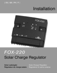
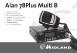
DE
BMI Datalog speed controller
Controllers
Vielen Dank dass Sie sich für dieses BMI Produkt entschieden haben. Hierbei handelt es sich um den BMI programmierbaren Drehzahlsteller mit
Data-Log Funktion.
Dieser sensorloser Drehzahlsteller benutzt die neueste Software, die ihm ermöglicht, mit allen Bürstenlosen Motoren kompatibel zu sein
- Die Data-Log Funktion speichert die Flugdaten, die nach dem Flug ausgelesen werden können mit der Databox
- Der Regler verfügt über einen Hochleistungs- SBEC , der in der Lage ist einen höheren Strom zu liefern, was den Einsatz von mehreren Servooperationen erlaubt.
- Der Regler kann man sowohl über den Sender als über die Programbox einstellen und programmieren.
Wir bieten die Spitz Regler und Motor an in 3 verschiedene Verpackungen, diese Anleitung ist für alle gültig.
- Spitz Turbo Brushless Motor + Zubehör
- Spitz Data-Log brushless Regler
- Spitz Combo Brushless Motor + Brushless Regler.
Haftung: BMI hat keine Kontrolle über die Verwendung, Handhabung oder eventuelle Produkt Modifikationen. Deshalb können keine Schadensersatzansprüche gegenüber BMI geltend gemacht werden. Ansprüche, die durch Anwendung, Ausfall oder Fehlfunktionen ausgelöst wurden, sind
ausgeschlossen. Für Personenschade, Sachschaden und deren Folgen die aus unserem Produkt oder Arbeit entstehen, können wir keine Haftung
übernehmen. Die Haftung wird im übrigen - soweit gesetzlich zulässig - beschränkt auf den Rechnungswert des schadenstiftenden Artikels.
Sobald das Gerät in Betrieb genommen wird, übernimmt der Benutzer alle daraus entstehende Verantwortlichkeit.
Für Haftungs- und Nachfolgeschäden beim Einsatz und Betrieb der von uns gelieferten Waren können wir nicht haften, da ein ordnungsgemäßer
Betrieb von uns nicht überwacht werden kann. Der Kunde ist verpflichtet die Ware unverzüglich nach dem Eintreffen am Bestimmungsort auf
Vollständigkeit und Ordnungsmäßigkeit sorgfältig zu überprüfen.
Garantie:
BMI garantiert, dass dieses Produkt beim Kauf frei von Fabrikations- und Materialfehlern ist. Schäden durch falschen Gebrauch oder Montagefehler werden durch diese Garantie nicht gedeckt. Wir haften nicht für Teile die beschädigt wurden während des Gebrauchs, für Schäden verursacht
durch Änderungen oder Zerstörungen, für Schäden zufolge der Benutzung von Klebstoffen jeglicher Art oder andere Produkte die nicht
ausdrücklich in der Anleitung beschrieben sind. Ausgeschlossen sind normaler Verschleiß im Betrieb, Unfallschäden, sowie Schäden, die durch
nichtbeachten dieser Bedienungsanleitung verursacht werden. Schaden durch unsachgemäßen Gebrauch, normaler Verschleiß, sowie Mangel,
die den Wert oder die Gebrauch Tauglichkeit des Gerätes nur unerheblich beeinflussen. Bei Eingriffen durch Nichts von uns autorisierte BMI
Kundendienstpartner sowie Verwendung anderer als Original BMI Ersatzteile erlischt die Garantie. Kurzschluss des Reglers oder Falschpolung der
Antriebsbatterie hebt der Garantie auf. Verwechslung oder Entfernung der Originalbekablung oder Connectoren, hebt der Garantie auf.
Ein Garantieanspruch ist nur gültig wenn:
- Das Produkt originalverpackt ist.
- Der Kassenbeleg mitgeschickt wird.
- Der Reparaturschein komplett ausgefüllt und mitgeschickt wird.
Drehzahlsteller für Brushless Motoren.
1) Installation
1. Kabelanschluss
- Verbinden Sie den Motor mit dem Regler (folgen Sie das Anschlussdiagramm). Verwenden Sie nur originelle, neu & isolierten Connectoren.
- Löten Sie Connectoren an die Stromkabeln und isolieren sie mit Schrumpfschlauch und kürzen sie die Stromkabel auf max. 12cm.
- Stecken Sie den JR Stecker im Gaskanal des Empfängers
- Verbinden Sie die Batterie mit dem Regler. Beachten Sie die Polarität. (Schwarzer Kabel zu Schwarzer Kabel/ Roter Kabel zu Roter Kabel)
1.2 Einbau der Regler
Bauen Sie den Regler im Modell ein mit Velcro oder doppelseitige Klebeband und beachten Sie dass der Regler frei von Shock und Vibrationen
ist. Vermeiden Sie einen Wärmestau im Regler. Eventuell Kühlungslocher im Rumpf machen. Ein Regler der nicht ausreichend gekühlt wird, kann
Schade verursachen.
2. Inbetriebnahme
- Stellen sie sicher, dass der Servoweg des Motor-/Gaskanals auf -+ 100 % gesetzt ist. Bei Futaba Sender und Sender die auf der Futaba Elektronik
basieren, müssen Sie Motor-/Gaskanal umdrehen
- Stellen Sie den Motor-/Gashebel auf die Minimum Position
- Schalten Sie Ihren Sender AN
- !! Nur für OPTO Regler : Verbinden Sie die Empfängerakku mit dem Empfänger
- !! Nur für Regler ausgestattet mit SBEC : Bei einem SBEC Regler Niemals Empfängerakku und Antriebsakku gleichzeitig anschließen, sonst wird
der Regler/Empfänger beschädigt
- Verbinden Sie die Antriebsbatterie mit dem Regler (SBEC)
- Wenn der Regler eingeschaltet wird, ertönt eine zweiteilige Folge von Piepssignalen, die den programmierten Zustand
des Drehzahlstellers anzeigen. Die erste Tonfolge steht für die Anzahl der Zellen einer LiPo Batterie, die mit dem Drehzahlsteller verbunden sind.
Die zweite Tonfolge gibt Aufschluss über den programmierten Bremszustand des Reglers. Ein Piepssignal (*) für: Bremse AN und zwei Piepser (**)
für: Bremse AUS.
- Der Drehzahlsteller kalibriert automatisch den Motor-/Gaskanal Regelbereich.
- Der Drehzahlsteller ist betriebsbereit.
3 Sicherheitshinweise
- Verbinden Sie die Antriebsbatterie unmittelbar vor dem Flug und trennen Sie diese kurz nach dem Flug wieder ab.
- Sobald der Akku angeschlossen ist, das Modell mit Respekt und Vorsicht behandeln.
- Stehen Sie niemals unmittelbar neben oder vor dem Propeller, Rotorblättern oder anderen beweglichen Teilen ihres Modells.
- Eine drehende Luftschraube kann sehr gefährlich sein, Sachen beschädigen und Personen verletzen.
- Auch wenn der Empfängerstromversorgung abgetrennt ist, kann der Antriebsakku noch angeschlossen sein. Behandeln Sie das Modell mit Vorsicht.
- Es ist die Verantwortlichkeit des Pilots um alle Connectoren zu prüfen auf Verpolung und gute Verbindung der Connectoren.
4. Programmieren des Reglers
Sie können der Regler auf 3 verschiedene Weise programmieren:
1) Mit dem Sender und Piepssignalen,
2) Mit der Program Box, mit dem Sie ebenfalls die Flugdaten auslesen können.
3) Mit der Program Card ( Program Karte)
5. Programmierung des Reglers mit dem Gashebel.
- Verbinden Sie den Regler mit dem Empfänger.
- Schalten Sie Ihren Sender AN und stellen Sie den Gashebel auf die Maximum Position
- Verbinden Sie die Batterie mit dem Spitz Data-Log Drehzahlsteller.(oder Empfängerakku bei einem OPTO Regler!)
- Bitte warten Sie auf 2 längere Signaltöne, gefolgt von 2 kurzen Signaltönen ( _ _ **).
- Wird nun innerhalb von 5 Sekunden der Motor-/Gashebel auf die Minimum Position gestellt, ertönt ein Signalton, mit der die Elektronik bestätigt,
dass die Programmierstellung der Bremse geändert wurde / Wird der Gashebel innerhalb von 5 Sekunden nicht bewegt, springt der Regler zum
nächsten Auswahlmenü (Batterietyp) und spielt die Tonfolgen der jeweiligen Programmieroption (siehe nachfolgende Tabelle),
- Wenn die Signalfolge für die erwünschte Stellung (ertönt, setzen Sie den Gashebel auf Minimum. Der Regler bestätigt dann die gewählte Programmierung mit 2 kurzen Pieptönen (* *).
- Der Regler befindet sich nun nicht mehr im Programmiermodus. Sind weitere Änderungen der Programmierung erwünscht, muss deshalb die Batterie vom Drehzahlsteller abgetrennt werden. Nach einer Pause von 5 Sekunden kann diese wieder mit dem Regler verbunden werden.
6. Programmierbare Einstellungen
6.1 MOTORBREMSE AN/AUS
ON (AN) Aktiviert die Bremse wenn der Gashebel auf Minimum gestellt
wird (Empfohlen für Klapp-Propeller) OFF (AUS) Bremse ist desaktiviert und
erlaubt das Rotieren des Propellers bei Gashebel auf Minimum
6.2 Batterie Type: LiPo oder NiCd/NiMH
NiCd/NiMH: Setzt den Schwellwert für den Unterspannungsschutz für NiCd/
NiMH Zellen. Wählt man als Batterietyp NiCd/NiMH, legt die Elektronik den
Schwellwert der Unterspannungserkennung (Cut-Off) automatisch auf den
Lieferzustand von 45%
LiPo: Setzt den Schwellwert für den Unterspannungsschutz (3.0V/Zelle) von
LiPo Zellen mit automatischer Erkennung der Zellenzahl.
6.3 Motor Drehrichtung
Normalerweise kann die Drehrichtung des Motors einfach durch das Umstecken zweier Motorkabel bewerkstelligt werden. Sind diese Motorkabel
jedoch direkt mit dem Drehzahlsteller verlötet oder im Modell nur schwer
zugänglich, kann die Drehrichtung des Motors mit dieser Programmierfunktion
umgekehrt werden.
6.4 Sanfter Anlauf
ENABLE (EIN ) Ermöglicht ein sanftes Anlaufen des Motors, in der die Motordrehzahl stetig in einer Sekunde auf den gewünschten Wert hochgefahren
wird, um weniger robuste Getriebe zu schützen, die unter einer plötzlich
einsetzenden last beschädigt werden könnten. Diese Einstellung ist empfohlen
für alle Flächen- und Hubschraubermodelle mit Getriebemotoren.
DISABLE(AUS): Ermöglicht schnelles und gleichmäßiges Anlaufen des Motors.
Das ist die empfohlene Einstellung für direkt betriebene Flächenmodelle.
NiMH/NiCd (45%)
•
LiPo auto detect
•• •• •• •• ••
Rotation reverse
W W W W W
•
•
•
•
Soft start
Enable
VV VV VV VV VV
Disable
V
V
V
V
V
Under voltage(cut off)
Ignore
_-- _-- _-- _-- _--
Reduce power
_- _- _- _- _- _-
Cut off
-_
-_ -_ -_ -_
Timing
Automatic (7-30°)
- - - - -
Soft (7°)
-- -- -- -- --
Hard (22-30°)
--- --- --- --- ---
Switching frequency
8 kHz
\ \ \ \ \
16 kHz
/ / / / /
Restore factory settings
6. 5 Programmierbare Tiefentladungsschutz. (Cut-off): Niedrig / Mittel / Hoch
Mit dieser Funktion Stellen ein, was passieren muss mit dem Motor, wenn die
Cut-off Spannung erreicht wird.
Activ RPM control
IGNORE (negieren): Der Motor bleibt drehen bis die Batterie leer ist.
RPM control off
Reduce Power (Leistungsreduzierung) : Der Regler reduziert die Motorleistung, sobald die Abschaltspannung erreicht wird.
RPM control on
HARD CUT-OFF (Abschalten) : Der Motor wird ausgeschaltet, sobald die
Abschaltspannung erreicht wird.
Sie haben immer die Möglichkeit , den normalen Betrieb wieder zu aktivieren, durch der Gashebel kurz in die
wieder Gas zu geben. Denken Sie daran so schnell wie möglich zu landen. .
_
_
_
_
_
_•_ _•_ _•_ _•_ _•_
_••_
_••_ _••_ _••_ _••_
Minimale Position zu bringen und
6.6 Timing setup
In den allermeisten Fällen funktioniert die automatische Erkennung des Timings hervorragend für alle Motorentypen. Für maximale Effizienz empfehlen wir die Einstellung “Niedrig” für 2 polige Motoren (normalerweise Innenläufer) und die Einstellung “Hoch” für 6- oder mehr polige Motoren
(normalerweise Aussenläufer). Um höhere Drehzahlen zu erreichen, kann die Einstellung “Hoch” gewählt werden. Einige Motoren benötigen unterschiedliche Timing Einstellungen, deshalb raten wir Ihnen, die von dem jeweiligen Herstellern empfohlenen Vorgaben zu folgen, oder sich auf die
gut funktionierende automatische Erkennung zu verlassen, wenn Sie sich bei den Timing Werten nicht sicher sind.
1
Low NIEDRIG (0°-7°) Einstellung für die meisten 2 poligen Motoren.
Automatic : AUTOMATISCH: Die Elektronik erkennt automatisch die optimale Einstellung.
High (22°-30°): Einstellung für 6 oder mehr poligen Motoren.
Battery type
2
Programming BOX Set Flow Chart
6.7 Switching frequency setup: 8kHz/16KHz (regelfrequenz)
8kHz: Optimiert für 2 Polige Motoren.
16kHz: Optimiert für mehrpolige Motoren.
* Anmerkung: Obwohl 16kHz eine effizientere Betriebsart mit unseren Spitz Motoren ermöglicht, ist aus Sicherheitsgründen im Lieferzustand 8kHz
gesetzt, da eine Einstellung von 16kHz etwas mehr Radio-Störsignale verursachen kann.
6.8. Wiederherstellung des Lieferzustandes
Brake : AUS
Battery Type: LiPo Automatisch
Under Voltage: Reduce power
Soft Start: Enabled
Timing : Auto
Frequency: 8kHz
RPM Control: Off
6.9 Active RPM control / Governor Mode (nur für Hubschrauber)
Disable: (AUS) : RPM Control off
Enable: (AN) RMP control on
B) PROGRAM BOX
Die Program Box wird optional verkauft und hilft Ihnen bei der Programmierung Ihres Data Log Reglers. Mit der Program Box können Sie ebenfalls
Die Flugdaten Ihres Data Log Reglers auslesen.
Mit der Program Box können Sie:
* Die Parameter Ihres Data Log brushless Regler programmieren
* Die Flugdaten, die während des Flugs gespeichert sind, auslesen.
1) Anschließen vom Regler
Verbinden Sie den Servokabel des Reglers mit dem Anschluss auf der
Programbox Box wie abgebildet.
Schließen sie eine Empfängerbatterie (4.8V~6.0V) an auf der Program
Box oder verwenden Sie die S-BEC Stromversorgung des Reglers. (Niemals gleichzeitig SBEC und Empfängerbatterie verwenden)
Drücken Sie 2x den ‘ ’ Knopf.
Drücken Sie abwechselnd auf ‘ ’ und ‘ ’
- Wenn Sie den Regler programmieren wollen, drücken Sie den ‘ ’ Knopf wenn „MAIN Setting“ auf dem Schirm erscheint.
- Wenn Sie den Regler auslesen wollen, drücken Sie den ‘ ’Knopf wenn „MEASURE“ auf dem Schirm erscheint.
2.1 Programmierung des Reglers mit der Program Box (Main setting)
Wahlen Sie erst ob Sie den Regler in einem Hubschrauber oder Flugzeug verwenden wollen.
Folgen Sie die Tabelle um die Parameter ein zu stellen.. Die Paramater sind die gleiche wie beschrieben in 6.
Folgende zusätzliche Parameter können auch mit der Program Box eingestellt werden:
- Zellenzahl für LiPo und Li-XX Batterien
- Abschaltspannung (Cut-off) für LiPo und Li-XX Batterien.
- Temperaturschutz. : Stellen Sie ein bei welcher Temperatur, der Motor abgeschaltet wird.
Folgen Sie die Tabelle.
2.2 Flugdaten auslesen
Die neue Spitz Data-Log Regler speichern Flugdaten während des Fluges. Nach dem Flug können diese Daten ausgelesen werden mit der Program
Box:
- Max / Umgebungstemperatur (°C)
- Min/Max. Strom (A)
- Min/Max /Aktuelle Spannung (V)
- Motorlaufzeit (sec)
- Power-on Zeit (sec)
- Zahl Motorpolen.
- Max U/Min
- Fehlermeldung
C) PROGRAM CARD
Eine andere Weise um einen Spitz Data-Log Regler zu programmieren ist mit der Programmier Karte (Program Card)
Führen Sie folgende Schritte aus:
- Stecken Sie die Jumper in die gewünschte Position, entsprechend Ihrer Auswahl.
- Anschlusskabel des Reglers (3-polige Servokabel) auf die RX Position der Programmier Karte stecken. Beachten Sie die Polarität !
- Verbinden Sie den Regler mit dem Akku. (Achtung: falls Sie einen OPTO Regler verwenden, ist es notwendig eine separate 4.8V Empfängerbatterie an zu schließen auf der Karte (EXT power))
- Nachdem der Regler eingeschaltet wird, hören Sie ein Signal, zur Bestätigung dass die Programmierung gut verlaufen ist und die Änderung
ausgeführt sind.
- Batterie und Regler von der programmierkarte trennen.
3
D) Brushless motoren
Beschreibung
Die Spitz Brushless Motoren bieten eine hervorragende Leistung und Effizienz, danke die besondere Neodym Magnete mit Idealen Kühlung und
geringes Gewicht. Das HVFCV (High Velocity Forced Cooled Ventilation) Kühlsystem hält das Innenleben der Motoren auf optimaler Betriebstemperatur. Alle Motoren sind ausgestattet mit 2 Kugellager, die größere Motoren (ab Spitz 15) mit drei Kugellager.
Warnungen
- Verwenden Sie nur einen brushless Regler in Kombination mit diesem Motor.
- Folgen Sie die Empfehlungen hinsichtlich Batterien en Luftschrauben. Beachten Sie dass die Luftschraube nicht zu groß ist. Eine zu große Luftschraube oder zu viele Zellen werden der Motor beschädigen.
- Verwenden Sie nur Connectoren, die die Stromanforderungen Ihres Motor gewaschen sind.
- Achten Sie darauf Ihren Motor nicht zu überheizen. Temperaturen höher als 80°C werden den Motor beschädigen.
- Montieren Sie keine Luftschraube bevor der Regler richtig programmiert ist. Eine drehende Luftschraube kann lebensgefährlich sein.
Anschluss
Verbinden Sie die drei Motorkabeln mit dem Regler. Sollte der Motor in der falschen Richtung drehen, tauschen Sie dann zwei Kabeln um.
4
EN
BMI Datalog speed controller
Controllers
Dear Customer, congratulations for purchasing our BMI Programmable Speed controller with Memo function.
This new generation ESC features the latest software, enabling it to work with every type of brushless motor.
- The memo function records flight data, which can be displayed afterwards on a separate program box.
- The ESC is equipped with an S-BEC, which offers higher BEC current, allowing to use more servos.
- This ESC can be programmed on the transmitter, with a program card or with a special program box, which also allows to read out the flight data.
We offer the Spitz controllers and motors in three different blisters, this manual is valid for all of them.
- Spitz Turbo Brushless motor + accessories
- Spitz Memo brushless speed controller
- Spitz Combo Brushless motor + brushless speed controller.
Liability: BMI has no control over the use, installation, application or maintenance of these products, thus no liability shall be assumed nor accepted for any
damages, losses or costs resulting from the use of this item. Any claims arising from the operating, failure or malfunctioning etc. will be denied. We assume no
liability for personal injury, property damage or consequential damages resulting from our product or our workmanship. As far as is legally permitted, the obligation for compensation is limited to the purchasing value of the product in question. By using speed controller or brushless motor, the user assumes the total
responsibility. BMI SA declines any liability for possible damages as a result of the use of its products. it is impossible to check on the correct use of product and
materials, proper installation, operation conditions at all times. and complying with any safety check so that BMI can therefore in no way be held responsible for
possible accidents. We affirm that the responsibility for the use of our products lies with the user.
Guarantee: We guarantee this product to be free of defects in materials and workmanship at the moment of purchase. This guarantee does not cover damage
due to the improper use , modifications or deteriorations following from the application of adhesives or other products not mentioned in the instructions, normal
wear and tear as well as defects that have a negligible effect on the value of operation of the product. We reserve the right to change or modify this guarantee
without previous notice. The guarantee becomes void if repairs are undertaken by unauthorized persons or if original BMI parts are not used. In no case guarantee is applicable when any of the original connectors are removed or replaced or when the speed controller or motor has suffered short circuit.
In case of a crash and blockage of the propeller, it is imperative to immediately cut the gas, in order to
prevent overheating and destruction of the motor or ESC
Products will only be accepted for warranty claims if:
- The product is in its original packaging.
- The product is accompanied with its original purchase receipt
- The product is accompanied with a completed repair form (download from www.bmi-models.com)
A) SPITZ ELECTRONIC SPEED CONTROLLER FOR BRUSHLESS MOTORS
1) Installation
1.1Connecting the wires
3. WARNINGS
- Always connect the battery pack just before flying and disconnect it immediately after landing.
- Once the battery pack is connected to the ESC, handle the model with extreme care.
- Stay away of a turning propeller at any time.
- A rotating propeller is extremely dangerous and may cause physical damage to persons and objects.
- Even if the S-BEC or receiver pack is disconnected or turned off, the main battery pack may still be connected. Handle the model with extreme care
- It is the pilots personal responsibility to double check all plugs for proper polarity and thight fit before the battery pack is connected.
4. How to program the controller
You can program the controller in 3 ways:
1) Using the transmitter and beep tones
2) Using a special program box, which also allows to read the flight data: for programming the ESC with the control box, please refer to the control
box chapter.
3) Using the program card
5. Programming the ESC with the transmitter sticks.
- Connect the ESC to the receiver
- Switch the transmitter ON and push the throttle stick to its maximum position.
- Connect the power battery pack to the controller (! OPTO ESC requires separate RX battery)
- Wait for 5 seconds until you hear two long audible tones, followed by two short beeps ( _ _ * *)
- If the throttle stick is lowered within 5 seconds to the minimum position, an audible tone is emitted confirming that the brake setting has been
changed.
- If the stick is left in its maximum position, (beyond the 5 sec.), the ESC will start sequencing from one setting to the next.
- When the desired tone for the function that you wish to change is reached, move the throttle stick down to the minimum position. The ESC will
beep twice (* *) confirming the new setting has been stored.
- You can set only one function at a time. Therefore if you wish to change another setting, disconnect the battery pack and wait for 5 seconds to
reconnect the battery pack and repeat the above steps.
- You can exit the programming mode at any time by disconnecting the power battery pack from the ESC.
Below is a table with all parameters and their emitted audible tones
6. Programmable Settings
6.1 Brake ON/OFF
ON: Sets the propeller to the brake position when the throttle stick is at the minimum position (for folding props)
OFF: Sets the propeller to rotate freely when the throttle stick is at the minimum position.
6.2 Battery Type: LiPo or NiCd/NiMH
NiCd/NiMH: Sets the Low Voltage protection threshold for NiCd/NiMH
Note: when NiCd/NiMH has been selected the ESC, the threshold value will
be set to 45% of the initial voltage.
LiPo: Sets the Low Voltage protection threshold for LiPo cells (3.0V/cell) and
automatically detects the number of cells within the battery pack.
- Connect your ESC to the motor according the wring diagram. Use high quality connectors only, make sure they are new and insulated with heat
shrink tube.
- Solder appropriate connectors to the battery wires and insulate all connectors with heat shrink tube. The maximum length of the battery pack
wires may in no case exceed 12 cm.
- Plug the JR connector into the throttle channel of the receiver
- Connect the battery to the ESC and be sure to respect the polarity (red wire to red wire, black wire to black wire)
1.2 Installation of the controller
Install the ESC in the model with Velcro or double sides tape so that the ESC is free from any shock or vibration.
Make sure there is sufficient cooling for the motor and controller. If necessary, make duct vents in the fuselage of your model for a better air
stream. Failure to cool the ESC or motor will cause damage.
2) Initialization.
- Switch on the transmitter and check that all the throttle setting in the transmitter are set to 100% if you have a computer radio. If you use a
Futaba transmitter, make sure to reverse the throttle channel before use.
- Put the throttle stick in the brake/minimum position.
- Turn on your transmitter
- For OPTO controllers only!! : Connect a receiver battery to your receiver
- For S-BEC controllers !!: never connect a receiver battery and S-BEC controller to the receiver at the same time. This may lead to damage of the
receiver and controller.
- Connect a battery pack to your controller, the receiver will now switch on (S-BEC)
- When the ESC is switched on , two series of beeps tones will sound, which indicate you the status of the ESC.
The first series will confirm the number of LiPo cells, connected with the ESC. Eg. If three beeps sound, the LiPo connected to the ESC battery
has three cells.
The next series of tones gives you information about the motor brake. One beep means that the brake is activated / Two beeps means that the
brake is off.
- The full throttle position will be calibrated automatically.
- The ESC is now ready to control and run the motor.
6.3 Rotation reverse.
The motor rotation sense is usually reversed by swapping over two motor
cables. However in some cases it might be necessary to change the rotation
sense with the program.
6.4 Soft start
Enable: When a gearbox is used or when the motor is installed in a helicopter, it is recommended to enable the soft start. This function provides a 1
second ramp-up from start to full rpm, intended to protect the gears.
Disable: For fixed models with direct drive , it is recommended to disable
the soft start function.
6.5 Low voltage cut-off (LVC)
Ignore: the motor keeps on running until the battery is totally empty
Reduce Power: The ESC reduces motor power when the preset low voltage
protection threshold is reached
Hard Cut-off: the ESC instantly cuts motor power when the pre-set low voltage protection threshold is reached.
Either one is active, you can resume normal operation by pulling down the
throttle stick and pushing it up again. Remember however to land the model
as soon as possible.
6.6 Timing setup
In most cases, automatic timing works well for all types of motors. However for high efficiency we recommend the low timing setting for 2-pole
motors(mostly in-runners) and high timing for 6 or more poles. (mostly
out-runners)
For higher speed, a higher timing can be set. Some motor require a special
timing setup. We suggest to follow the manufacturer’s recommended setup
or to use the automatic timing if you are unsure.
Low (0°-7°): Setting for most 2 pole motors
Automatic : The ESC automatically determines the best motor timing
High (22°-30°): Setting for motors with 6 or more poles.
1
Battery type
NiMH/NiCd (45%)
•
LiPo auto detect
•• •• •• •• ••
•
•
•
•
Rotation reverse
W W W W W
Soft start
Enable
VV VV VV VV VV
Disable
V
V
V
V
V
Under voltage(cut off)
Ignore
_-- _-- _-- _-- _--
Reduce power
_- _- _- _- _- _-
Cut off
-_
-_ -_ -_ -_
Timing
Automatic (7-30°)
- - - - -
Soft (7°)
-- -- -- -- --
Hard (22-30°)
--- --- --- --- ---
Switching frequency
8 kHz
\ \ \ \ \
16 kHz
/ / / / /
Restore factory settings _
_
_
_
_
Activ RPM control
RPM control off
_•_ _•_ _•_ _•_ _•_
RPM control on
_••_
_••_ _••_ _••_ _••_
2
Follow the flow chart to program your ESC to your specific needs.
6.7 Switching frequency setup: 8kHz/16KHz
8kHz: Sets the switching frequency for 2 pole motors, eg. out-runners
16kHz: for motors with more than 2 poles: eg out-runners.
* 16kHz will be more efficient with Spitz motors, but 8kHz is set as default due to lower RF noises.
6.8 Restore to factory settings
This functions will reset all parameters to the original factory set-up.
Brake : Off
Battery Type: 3S LiPo
Under Voltage: Reduce power
Soft Start: Enabled
Timing : Auto
Frequency: 8KHz
RPM Control: Off
6.9 Active RPM control / Governor Mode (for helicopters only)
Disable: RPM Control off
Enable: RMP control on
B) SPITZ PROGRAM CARD
Another way to program the ESC in a very visual way, is by using the program card. Proceed as follows:
- Placed the jumpers into the desired positions, according to your preferences.
- Connect the ESC cable to the RX-pins on top of the program card. Pay attention to the polarity !!
- Connect the battery to your ESC. REMARK : When using an OPTO controller, it is required to connect a 4,8 V battery to the Ext. Power Pins on
the program card.
- Switch on the ESC (if applicable) and you will hear a beep tone to inform you that the settings have been changed.
- Remove the battery and disconnect the ESC from the program card.
C) PROGRAM BOX
The Program Box is not included and is available as an option. However it can help you a lot programming your ESC to your personal parameters.
The program Box also has the possibility to display the flight data after landing.
It is pocket-sized, so you can bring it to the flying field conveniently.
The advanced program box is used for two purposes:
A) To set the programmable parameters of your ESC.
B) To read out the flight data, stored in the ESC
1) Connection of the ESC to the Program Box
Connect the servo lead of the ESC to the Program Box as displayed and connect a receiver battery to the box as well or use the S-BEC power
supply of your ESC.
Next press the ‘down’-key twice.
Alternating press the left-key and the right-key.
- If you want to program the ESC settings, press the down-key when ‘Main Setting’ appears on the display.
- If you want to read out the ESC data, press the down-key when ‘Measure’ appears on the screen.
2.1 Programming the ESC with the Program Box (main setting)
First, choose whether you want to use the ESC in an airplane or helicopter.
Set the parameters according the flow chart below. You can set the same parameters as described in chapter 6.
There are additional settings that can only be set, using the program box.
- The number of cells, when using LiPo batteries and Ni-XX batteries
- Cut-off voltage when using LiPo or Ni-XX batteries
- Temperature Protection : Sets the temperature at which the ESC will stop the motor.
2.2 Flight Data
The new Spitz MEMO speed controllers have a memory that stores flight date. After flying, you have the possibility to consult these flight data
using the data log program box:
- Max / Environment Temperature (°C)
- Min/Max. Current (A)
- Min/Max /Actual / Off Voltage (V)
- Motor runtime (sec)
- Power on time (sec)
- Motor Pole No.
- Max motor RPM
- Errors
3
D) SPITZ BRUSHLESS MOTORS
Description
The Spitz brushless motors offer great efficiency in comparison to their low weight and the wide range going from 60W to 1200W witch allow you
to power almost every model from 200g up to 7kg. The lightweight, CNC milled design has 14 special and powerful Neodymium magnets, which
offer more torque, permitting to run larger propellers or more pitch. The especially designed High Velocity Forced Cooled Ventilation consists of
small metal turbine blades in the cage, that forces ventilation through the stator and magnets. This offers a magnificent stability in temperature
and high efficiency while flying. All motors are equipped with 2 high quality, high rpm ball bearings. Larger motors (as from Spitz .15 ) have a 3rd
concentric bearing in the stator. Every motor is equipped with a hardened steel axle.
Warnings
- Keep in mind that only a brushless electronic speed controller (ESC) can be used with these motors.
- Use only the recommended number of battery cells and respect the recommended propeller size. A too big propeller or too many cells will
deteriorate the motor and damage it.
- Only use connectors that are capable of coping with the current draw of your motor.
- Pay attention to never overheat your motor. If the temperature exceeds 80°C, the magnets may be affected and lose efficiency.
- Do not install a propeller until your ESC is programmed and working correctly. A rotating propeller can cause serious injury
Connection
Connect the three wires from the motor to the ESC. In case that the motor turns into the wrong direction, change two cables till the motor turns
correctly.
4