1
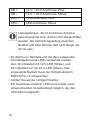
Installations- und Bedienungsanleitung (S. 2) Installation and operating manual (p. 30) Funk-Dimmaktor 1-fach, PWM LED, Zwischendeckenmontage Wireless Dimming Actuator 1-channel, PWM LED, ceiling-void mount HM-LC-Dim1PWM-CV 1. Ausgabe Deutsch 09/2011 Dokumentation © 2011 eQ-3 AG, Deutschland Alle Rechte vorbehalten. Ohne schriftliche Zustimmung des Herausgebers darf dieses Handbuch auch nicht auszugsweise in irgendeiner Form reproduziert werden oder unter Verwendung elektronischer, mechanischer oder chemischer Verfahren vervielfältigt oder verarbeitet werden. Es ist möglich, dass das vorliegende Handbuch noch drucktechnische Mängel oder Druckfehler aufweist. Die Angaben in diesem Handbuch werden jedoch regelmäßig überprüft und Korrekturen in der nächsten Ausgabe vorgenommen. Für Fehler technischer oder drucktechnischer Art und ihre Folgen übernehmen wir keine Haftung. Alle Warenzeichen und Schutzrechte werden anerkannt. Printed in Hong Kong Änderungen im Sinne des technischen Fortschritts können ohne Vorankündigung vorgenommen werden. 99292 / V 1.1 2 Inhaltsverzeichnis 1 Hinweise zu dieser Anleitung . . . . . . . . . . . . . . 4 2Gefahrenhinweise . . . . . . . . . . . . . . . . . . . . . . . 5 3Funktion . . . . . . . . . . . . . . . . . . . . . . . . . . . . . . 8 4 Allgemeine Systeminformation zu HomeMatic 10 5 Allgemeine Hinweise zum Funkbetrieb . . . . . . 10 6Installation . . . . . . . . . . . . . . . . . . . . . . . . . . . . 12 6.1Montageort . . . . . . . . . . . . . . . . . . . . . . . . . . . 15 6.2Montage . . . . . . . . . . . . . . . . . . . . . . . . . . . . . 15 7Inbetriebnahme . . . . . . . . . . . . . . . . . . . . . . . . 17 7.1 Einfache Bedienfunktionen am Gerät . . . . . . . 17 7.2Anlernen . . . . . . . . . . . . . . . . . . . . . . . . . . . . . 18 7.2.1 Anlernen an HomeMatic Geräte . . . . . . . . . . . 18 7.2.2 Anlernen an eine HomeMatic Zentrale . . . . . . 19 8Bedienung . . . . . . . . . . . . . . . . . . . . . . . . . . . . 23 9 Zurücksetzen in den Auslieferungszustand . . . 23 10 Rückmeldungen der Geräte-LED . . . . . . . . . . 24 10.1Blinkcodes . . . . . . . . . . . . . . . . . . . . . . . . . . . . 24 10.2 Anzeige des Betriebszustandes . . . . . . . . . . . 24 11 Verhalten nach Spannungswiederkehr . . . . . . 25 12Wartung . . . . . . . . . . . . . . . . . . . . . . . . . . . . . . 25 13 Weitere Betriebshinweise . . . . . . . . . . . . . . . . 27 14 Technische Daten . . . . . . . . . . . . . . . . . . . . . . 27 3 1 Hinweise zu dieser Anleitung Lesen Sie diese Anleitung sorgfältig, bevor Sie Ihre HomeMatic Komponenten in Betrieb nehmen. Bewahren Sie die Anleitung zum späteren Nachschlagen auf! Wenn Sie das Gerät anderen Personen zur Nutzung überlassen, übergeben Sie auch diese Bedienungsanleitung. Benutzte Symbole: Achtung! Hier wird auf eine Gefahr hingewiesen. Hinweis. Dieser Abschnitt enthält zusätzliche wichtige Informationen! Hinweis. Dieser Abschnitt enthält zusätzliche wichtige Informationen zur Verwendung des Gerätes in Verbindung mit der HomeMatic Zentrale. 4 2Gefahrenhinweise Der beschriebene Aktor ist Teil einer Gebäudeinstallation. Bei der Planung und Errichtung von elektrischen Anlagen sind die einschlägigen Normen und Richtlinien des Landes zu beachten, in dem die Anlage installiert wird. Der Betrieb des Gerätes ist ausschließlich an einem externen Netzteil (12-24 VDC) zulässig, das entsprechend der Gesamt-Anschlussleistung der LEDs auszuwählen ist. Die Ausgangsleistung des Netzteils sollte immer höher als die benötigte Leistung sein, um unnötige Erwärmung zu vermeiden und Leistungsreserven zur Verfügung zu haben. Die Installationshinweise im Kapitel „Installation” sind unbedingt zu beachten. Bei Nichtbeachtung der Installationshinweise können Brand oder andere Gefahren entstehen. 5 Betreiben Sie das Gerät nur in Innenräumen und vermeiden Sie den Einfluss von Feuchtigkeit, Staub sowie Sonnen- oder andere Wärmebestrahlung. Die für LED-Beleuchtungen einsetzbaren Netzteile müssen neben den EMV-Normen EN55015, EN61000-3-2, EN61000-3-3 und EN61547 auch die Sicherheitsnorm EN613472-13 einhalten. Belasten Sie die Geräte nur bis zur angegebenen Leistungsgrenze. Eine Überlastung kann zur Zerstörung des Gerätes, zu einem Brand oder elektrischen Unfall führen. Öffnen Sie das Gerät nur zum Sicherungswechsel. Beachten Sie dabei die Sicherheitshinweise. Beachten Sie beim Anschluss an die Geräteklemmen die hierfür zulässigen Leitungen und Leitungsquerschnitte. 6 Das Gerät ist kein Spielzeug. Erlauben Sie Kindern nicht damit zu spielen. Lassen Sie Verpackungsmaterial (Plastikfolien/-tüten, Styroporteile etc.) nicht achtlos liegen. Dies kann für Kinder zu einem gefährlichen Spielzeug werden. Reinigen Sie das Gerät nur mit einem trockenen Leinentuch, das bei starken Verschmutzungen leicht angefeuchtet sein kann. Verwenden Sie zur Reinigung keine lösemittelhaltigen Reinigungsmittel. Achten Sie darauf, dass keine Feuchtigkeit in das Geräteinnere gelangt. 7 3Funktion Der Aktor steuert angeschlossene LED-Anordnungen bis zu einer Leistungsaufnahme von 60 W aufgrund von empfangenen Funkbefehlen. Befehle werden ausgesandt durch Betätigung von Tastern, Fernbedienungen oder über eine Softwareoberfläche. Zusätzlich ist es möglich, Aktoren über angelernte Sensoren anzusteuern. Die Sensoren senden (wie ein Taster) beim Eintreten eines Ereignisses einen Befehl. Genaueres dazu ist der Anleitung des entsprechenden Sensors zu entnehmen. Alle programmierten Daten bleiben in einem integrierten Speicher dauerhaft erhalten - auch bei Netzausfall. Jeder andere Einsatz, als in dieser Bedienungsanleitung beschrieben, ist nicht bestimmungsgemäß und führt zu Garantie- und Haftungsausschluss. Dies gilt auch für Umbauten und Veränderungen. Das Gerät ist ausschließlich für den privaten Gebrauch gedacht. 8 LED UB AAnschlussklemmen BGeräte-LED CKanaltaste DBefestigungslaschen 9 4 Allgemeine Systeminformation zu HomeMatic Dieses Gerät ist Teil des HomeMatic-Haussteuerungs-Systems und arbeitet mit dem bidirektionalen BidCoS®-Funkprotokoll. Alle Geräte werden mit einer Standardkonfiguration ausgeliefert. Darüber hinaus ist die Funktion des Gerätes über ein Programmiergerät und Software konfigurierbar. Welcher weitergehende Funktionsumfang sich damit ergibt, und welche Zusatzfunktionen sich im HomeMatic-System im Zusammenspiel mit weiteren Komponenten ergeben, entnehmen Sie bitte dem HomeMatic WebUI Handbuch. Alle technischen Dokumente und Updates finden Sie stets aktuell unter www.homematic.com. 5 Allgemeine Hinweise zum Funkbetrieb Die Funk-Übertragung wird auf einem nicht exklusiven Übertragungsweg realisiert, weshalb Störungen nicht ausgeschlossen werden können. Weitere Störeinflüsse können hervorgerufen werden durch Schaltvorgänge, Elektromotoren oder defekte Elektrogeräte. 10 Die Reichweite in Gebäuden kann stark von der im Freifeld abweichen. Außer der Sendeleistung und den Empfangseigenschaften der Empfänger spielen Umwelteinflüsse wie Luftfeuchtigkeit neben baulichen Gegebenheiten vor Ort eine wichtige Rolle. Wird beim Dimmaktor die „gesicherte Übertragung“ (AES) aktiviert, bedeutet dies: • höheres Kommunikationsaufkommen, • Aktor-Gruppen können nicht mehr gleichzeitig Befehle ausführen, • Dimmen über eine HomeMatic Fernbedienung nur noch mit reduzierter Geschwindigkeit sowie • Dimmen mit mehr als einem Gerät pro Senderkanal / Tastenpaar ist nicht mehr möglich. Weitere Informationen zur gesicherten Übertragung (AES) finden Sie im HomeMatic WebUI Handbuch unter www.homematic.com. Hiermit erklärt die eQ-3 AG, dass sich dieses Gerät in Übereinstimmung mit den grundlegenden Anforderungen und den anderen relevanten Vorschriften der Richtlinie 1999/5/EG befindet. Die vollständige Konformitätserklärung finden Sie unter www.homematic.com. 11 6Installation Wenn Sie das 12-V-/24-V-Netzteil von der Netzspannung trennen, beachten Sie bitte die folgenden 5 Grundregeln: • Stromkreis freischalten • Gegen Wiedereinschalten sichern • Spannungsfreiheit feststellen • Erden und Kurzschließen • Benachbarte, unter Spannung stehende Teile abdecken oder abschranken Der Aktor zur Zwischendeckenmontage eignet sich zur unsichtbaren Montage etwa in abgehängten Decken. Zur bequemen Befestigung mit Schrauben sind am Gerät Befestigungslaschen angebracht. Die Installation des Aktors ist im nachfolgenden Anschlussbild dargestellt: 12 Bei weiteren Verteilungen: Abstand zwischen erster und letzter Verteilung: max. 1 m 1. Verteilung letzte Verteilung bis Ende letzter Stripe max. 4 m HM-LC-Dim1PWM-CV-2 13 UB + 12 V- / 24-V-Anschluss, Plus UB – 12-V- / 24-V-Anschluss, Minus LED + LED-Anschluss, Plus LED – LED-Anschluss, Minus Leitungslängen, die im Anschluss-Schema gekennzeichnet sind, dürfen nicht überschritten werden. Die Verbindungsleitung zwischen Netzteil und LED-Dimmer darf nicht länger als 30 cm sein. • Es dürfen nur Netzteile und die dazu passenden Konstantspannungs-LEDs verwendet werden, also 12-V-Netzteil mit 12-V-LED (Stripe), und 24-V-Netzteil nur mit 24-V-LED (Stripe). Das eingesetzte Netzteil muss der Sicherheitsnorm EN61347-2-13 entsprechen. • Achten Sie auf die richtige Polarität. • Ein Anschluss einzelner LEDs ist nur über einen entsprechenden Vorwiderstand möglich, der den LED-Strom begrenzt! 14 Zugelassene Leitungsquerschnitte: starre Leitung flexible [mm2] Leitung ohne Aderendhülse [mm2] flexible Leitung mit Aderendhülse [mm2] 1,00 – 2,50 1,00 – 2,50 1,00 - 2,50 6.1Montageort Bei der Auswahl des Montageortes ist zu beachten, dass dieser trocken, staubfrei und ausreichend belüftet sein sollte, um eine ausreichende Luftzirkulation zu gewährleisten. Auch eine Wärmebelastung, etwa durch direkte Sonneneinstrahlung, Heizrohre etc., ist zu vermeiden. Bei ausreichender Luftzirkulation um das Gerät herum ist ein Einbau in Möbel oder Holzdecken zulässig (Einbaukennzeichnung siehe „Technische Daten”). 6.2Montage • Entfernen Sie die Kabelabdeckung des Dimmers durch Herausschrauben der Befestigungsschraube. • Isolieren Sie die Drahtenden des Verbindungskabels zwischen Dimmer und Netzteil sowie LEDs vorsichtig auf eine Länge von 8 mm ab. 15 • Verbinden Sie den Dimmer mit dem Netzteil und den LEDs entsprechend der Skizze auf Seite 11. • Vergewissern Sie sich, dass alle Anschlüsse fest und sicher verschraubt sind, ohne dass ein Kurzschluss zwischen den beiden Adern entstehen kann. Beachten Sie, dass die Leitungen zu den LEDStripes ausreichend entsprechend dem Strombedarf und der Anzahl der LED-Stripes sowie der Gesamt-Leitungslänge dimensioniert sind, um zu gewährleisten, dass alle Stripes die volle Betriebsspannung erhalten und es zu keiner Überhitzung der Leitungen kommen kann. • Schließen Sie das Gehäuse des Dimmers durch Aufsetzen und Verschrauben der Kabelabdeckung. Dabei ist darauf zu achten, dass die Leitungen durch die als Zugentlastung dienenden Klemmrippen des Gerätegehäuses sicher erfasst und fixiert sind. • Die Montage des Dimmers erfolgt über die Befestigungslaschen, die fest mit dem Untergrund zu verschrauben sind. Die Anschlussleitungen müssen im Zuge ihrer Verlegung fixiert werden, z. B. durch Nagel- oder Klemmschellen, Rohre oder 16 Kabelkanäle. • Ist das Netzteil über einen Netzstecker an das Stromnetz anzuschließen, stecken Sie nun den Netzstecker in eine Netzsteckdose. • Ist hingegen ein fester Anschluss, z. B. über eine Verteilerdose, vorgesehen, ist zunächst der betroffene Stromkreis vom Netz zu trennen (siehe Abschnitt 2. Gefahrenhinweise). • Schließen Sie dann das Netzteil an den Stromkreis an. • Schalten Sie die Spannung erst wieder zu, wenn alle Leitungen und Verteilelemente fixiert und Verteilerdosen geschlossen sind. 7Inbetriebnahme 7.1 Einfache Bedienfunktionen am Gerät Über die Kanaltaste können Sie den Aktor sofort bedienen (Anlernen nicht erforderlich) und die korrekte elektrische Installation überprüfen. Der Taster verhält sich wie ein AN/AUS Toggle-Taster. Zum Bedienen wird nur der kurze Tastendruck verwendet. Der lange Tastendruck (länger als 4 Sekunden) versetzt den Aktor in den Anlernmodus. 17 7.2Anlernen Bitte lesen Sie diesen Abschnitt vollständig, bevor Sie mit dem Anlernen beginnen. Damit der Funk-Dimmaktor in Ihr HomeMatic System integriert wird und mit anderen HomeMaticKomponenten (z. B. einer HomeMatic Fernbedienung) kommunizieren kann, muss das Gerät zunächst angelernt werden. Sie können den HomeMatic FunkDimmaktor an andere HomeMatic-Geräte oder an die HomeMatic Zentrale anlernen: 7.2.1Anlernen an HomeMatic Geräte Wenn Sie den Funk-Dimmaktor an ein oder mehrere Geräte anlernen möchten, müssen die beiden zu verknüpfenden Geräte in den Anlernmodus gebracht werden. Dafür gehen Sie wie folgt vor: Halten Sie beim Anlernen einen Mindestabstand von 50 cm zwischen den HomeMatic Geräten ein. Aktivieren Sie zunächst den Anlernmodus am FunkDimmaktor. • Halten Sie die Kanaltaste für mindestens 4 Sekunden gedrückt. Dauerhaftes Blinken der 18 Geräte-LED signalisiert den Anlernmodus. Die Anlernzeit beträgt max. 20 Sekunden. • Versetzen Sie jetzt das Gerät, das Sie an den FunkDimmaktor anlernen möchten, in den Anlernmodus. Bitte entnehmen Sie der Bedienungsanleitung des Anlernpartners, wie Sie ihn in den Anlernmodus versetzen. Wenn kein Anlernen erfolgt, wird der Anlernmodus automatisch nach 20 Sekunden beendet. Befinden sich andere Geräte im Anlernmodus, werden diese angelernt. 7.2.2Anlernen an eine HomeMatic Zentrale Um Ihr Gerät softwarebasiert und komfortabel • steuern und konfigurieren, • direkt mit anderen Geräten verknüpfen oder • in Zentralenprogrammen nutzen zu können, muss es zunächst an die HomeMatic Zentrale angelernt werden. Das Anlernen neuer Geräte an die Zentrale erfolgt über die HomeMatic Bedienoberfläche „WebUI“. 19 Sobald eine Komponente an eine Zentrale angelernt ist, kann sie nur noch über diese mit anderen Komponenten verknüpft werden. Jede Komponente kann immer nur an eine Zentrale angelernt werden. Halten Sie beim Anlernen einen Mindestabstand von 50 cm zwischen den HomeMatic Geräten und der Zentrale ein. Zum Anlernen Ihres Gerätes an die Zentrale gehen Sie wie folgt vor: • Öffnen Sie die WebUI-Bedienoberfläche in Ihrem Browser. Klicken Sie auf den Button „Geräte anlernen“ im rechten Bildschirmbereich. • Um den Anlernmodus zu aktivieren, klicken Sie auf „BidCoS-RF Anlernmodus“. 20 • Der Anlernmodus ist für 60 Sekunden aktiv. Das Infofeld zeigt die aktuell noch verbleibende Anlernzeit. • Versetzen Sie innerhalb dieser Anlernzeit auch den Funk-Dimmaktor in den Anlernmodus. Halten Sie die Kanaltaste für mindestens 4 Sekunden gedrückt. Dauerhaftes Blinken der Geräte-LED signalisiert den Anlernmodus. • Nach kurzer Zeit erscheint das neu angelernte Gerät im Posteingang Ihrer Bedienoberfläche. Der Button „Posteingang“ zeigt dabei an, wie viele neue Geräte erfolgreich angelernt wurden. • Lernen Sie ggf. weitere Geräte an, indem Sie die vorher beschriebenen Schritte für jedes Gerät wiederholen. • Konfigurieren Sie nun die neu angelernten Geräte im Posteingang wie im Abschnitt „Neu angelernte Geräte konfigurieren“ beschrieben. Neu angelernte Geräte konfigurieren Nachdem Sie Ihren Funk-Dimmaktor an die HomeMatic Zentrale angelernt haben, wird er in den „Posteingang“ verschoben. Hier muss Ihr Gerät und die dazugehörigen Kanäle zunächst konfiguriert werden, damit es für Bedien- und Konfigurationsaufgaben zur Verfügung steht. Vergeben Sie einen Namen und ord21 nen Sie das Gerät einem Raum zu. Sie haben zusätzlich die Möglichkeit, einzelne Parametereinstellungen vorzunehmen. Anschließend können Sie Ihr Gerät über die WebUI steuern und konfigurieren, direkt mit anderen Geräten verknüpfen oder in Zentralenprogrammen nutzen. Einzelheiten hierzu entnehmen Sie bitte dem HomeMatic WebUI Handbuch (zu finden im Download-Bereich der Website www.homematic.com). 22 8Bedienung Nach dem Anlernen stehen einfache Bedienfunktionen über die angelernten Bedienelemente zur Verfügung. Kurzer Tastendruck: AN/AUS, langer Tastendruck: Dimmen. Dabei ergibt sich folgendes Verhalten: Taste Verhalten Kurzer Tastendruck „EIN“-Taste AN Kurzer Tastendruck „AUS“-Taste AUS Langer Tastendruck „EIN“-Taste Hoch dimmen Langer Tastendruck „AUS“-Taste Runter dimmen 9 Zurücksetzen in den Auslieferungszustand Um den Aktor in den Auslieferungszustand zurückzusetzen, versetzen Sie das Gerät über die Kanaltaste in den Anlernmodus (mindestens 4 Sekunden Taste gedrückt halten). Befindet sich das Gerät im Anlernmo23 dus, halten Sie erneut die Kanaltaste für mindestens 4 Sekunden gedrückt. Schnelles Blinken der GeräteLED zeigt das Rücksetzen des Aktors an. 10 Rückmeldungen der Geräte-LED 10.1Blinkcodes Verschiedene Zustände des Aktors werden durch Blinken der Kanal-LED angezeigt: Langsames Blinken Anlernmodus Schnelles Blinken Reset Einmal lang, n-mal kurz (je nach Fehlerart) Fehler 10.2Anzeige des Betriebszustandes Sobald der Dimmer eingeschaltet ist, leuchtet die Geräte-LED dauerhaft. Nach Konfiguration des Aktors über die Zentrale oder über ein Programmiertool zeigt die Geräte-LED neben den beschriebenen noch zusätzliche Zustände des Gerätes an. 24 11 Verhalten nach Spannungswiederkehr Nach dem Einschalten der Betriebsspannung (Wiederkehr der Netzspannung) überprüft der Aktor seine Komponenten. Sollte dabei ein Fehler festgestellt werden, so wird dieses durch Blinken der LED dargestellt. Dieses wiederholt sich kontinuierlich und das Gerät nimmt seine eigentliche Funktion nicht auf. Sollte der Test ohne Fehler durchlaufen, sendet der Aktor ein Funktelegramm mit seiner Statusinformation aus. Damit bei Spannungswiederkehr (etwa nach Netzspannungsausfall oder Abschaltung) nicht alle Aktoren gleichzeitig senden, wartet der Aktor eine zufällige Verzögerungszeit vor dem Senden. In dieser Zeit blinkt die Geräte-LED (wie im Anlernmodus). Ist die Verzögerungszeit sehr kurz, kann es sein, dass das Blinken kaum wahrnehmbar ist. 12Wartung Das Produkt ist wartungsfrei. Es darf nur zum Sicherungswechsel geöffnet werden. Zur Sicherung des Gerätes gegen Überlastung ist es 25 mit einer Mini-Kfz-Flachsicherung (7,5 A) gesichert. Diese befindet sich auf der Platine innerhalb des Dimmergehäuses. Trennen Sie das 12-V-/24-VNetzteil von der Netzspannung (siehe Abschnitt 2. Gefahrenhinweise). • Öffnen Sie das Gehäuse des Dimmers durch Herausdrehen der vier Gehäuseschrauben am Gehäuseboden und Abnehmen des Gehäuseoberteils. • Entnehmen Sie die Sicherung aus dem Halter (Lage siehe Markierung im Bild) und tauschen sie gegen eine Mini-Kfz-Flachsicherung 7,5 A aus. • Tauschen Sie die Sicherung nur gegen eine Sicherung des gleichen Typs aus, nachdem Sie die Ursache der Überlastung dauerhaft beseitigt haben! • Schließen Sie das Gehäuse des Dimmers. • Nehmen Sie den Dimmer wieder in Betrieb. 26 13 Weitere Betriebshinweise Erwärmt sich das Gerät im Betrieb zu stark, z. B. durch ungenügende Luftzirkulation, erfolgt zunächst eine Lastreduzierung in Form einer Helligkeitsabsenkung, bei anhaltender Übertemperatur erfolgt ein Abschalten der Last. Bei Betrieb des Aktors über die Zentrale des HomeMatic-Systems (CCU) ist zu beachten, dass die Zentrale keine Information bei einem Lastausfall erhält. 14 Technische Daten Geräte-Kurzbezeichnung: Versorgungsspannung: Maximale Schaltleistung: Stromaufnahme: Leistungsaufnahme Ruhebetrieb: Dimmverfahren: Lastart: HM-LC-Dim1PWM-CV 12 VDC - 24 VDC 60 W (5 A@12 V; 2,5 A@24 V) 5 A max. 0,8 W Pulsweitenmodulation (PWM) Konstantspannungs-LEDs 27 (ohmsche Last) Leitungsart u. -querschnitt: starre und flexible Leitung, 1,0–2,5 mm² Funkfrequenz: 868,3 MHz Empfängerklasse: SRD Class 2 Typ. Freifeldreichweite: > 100 m Duty Cycle: < 1 % pro h Maximale Sendeleistung: 10 mW Schutzart: IP20 Schutzklasse: III Umgebungstemperatur: 5 bis 50 °C Geräteschutz: Überlastsicherung, Temperatursicherung Abmessungen (B x H x T): 49 x 34 x 148 mm (mit Laschen) Gewicht: 87 g Einbaukennzeichnung: F Leuchte zur Montage an oder auf schwer entflammbaren Baustoffen MM Montage auf Materialien, deren Entflammeigenschaften nicht bekannt sind, wobei im Normalfall 95° C und sowohl im anormalen Betrieb als auch im 28 Fehlerfall 115° C nicht überschritten werden. Technische Änderungen vorbehalten. Entsorgungshinweis Gerät nicht im Hausmüll entsorgen! Elektronische Geräte sind entsprechend der Richtlinie über Elektro- und ElektronikAltgeräte über die örtlichen Sammelstellen für Elektronik-Altgeräte zu entsorgen. Das CE-Zeichen ist ein Freiverkehrszeichen, das sich ausschließlich an die Behörden wendet und keine Zusicherung von Eigenschaften beinhaltet. 29 1st English edition 09/2011 Documentation © 2011 eQ-3 AG, Germany All rights reserved. No parts of this manual may be reproduced or processed in any form using electronic, mechanical or chemical processes in part or in full without the prior explicit written permission of the publisher. It is quite possible that this manual has printing errors or defects. The details provided in this manual are checked regularly and corrections are done in the next edition. We do not assume any liability for technical or printing errors. All registered trade marks and copyrights are acknowledged.Printed in Hong Kong We reserve the right to make changes due to technical advancements without prior notice. 99292 / V 1.1 30 Table of Contents 1 Information concerning these instructions . . . . 2 Hazard information . . . . . . . . . . . . . . . . . . . . . 3Function . . . . . . . . . . . . . . . . . . . . . . . . . . . . . 4 General system information on HomeMatic . . 5 General information on radio operation . . . . . . 6Installation . . . . . . . . . . . . . . . . . . . . . . . . . . . . 6.1 Mounting site . . . . . . . . . . . . . . . . . . . . . . . . . . 6.2Mounting . . . . . . . . . . . . . . . . . . . . . . . . . . . . . 7 Start up . . . . . . . . . . . . . . . . . . . . . . . . . . . . . . 7.1 Simple operating functions on the device . . . . 7.2Teaching . . . . . . . . . . . . . . . . . . . . . . . . . . . . . 6.2.1 Teaching-in to HomeMatic devices . . . . . . . . . 6.2.2 Teaching in to a HomeMatic CCU . . . . . . . . . . 8Operation . . . . . . . . . . . . . . . . . . . . . . . . . . . . 9 Resetting to factory status . . . . . . . . . . . . . . . . 10 Device LED feedback messages . . . . . . . . . . 10.1 Flash codes . . . . . . . . . . . . . . . . . . . . . . . . . . . 10.2 Operational status display . . . . . . . . . . . . . . . . 11 Behavior after power restoration . . . . . . . . . . . 12 Maintenance and cleaning . . . . . . . . . . . . . . . 13 Other notes on operation . . . . . . . . . . . . . . . . 14 Technical specifications . . . . . . . . . . . . . . . . . . 32 33 35 37 37 39 42 42 44 44 44 45 46 48 49 49 49 50 50 51 52 52 31 1 Information concerning these instructions Read these instructions carefully before beginning operation with your HomeMatic components. Keep the instructions handy for later consultation! Please handover the operating manual as well when you hand-over the device to other persons for use. Symbols used: Attention! This indicates a hazard. Note. This section contains additional important information! Note. This section contains additional important information about using the device in connection with the HomeMatic Central Control Unit. 32 2 Hazard information The described actuator is a part of a building installation. When planning and setting up electrical systems, the pertinent standards and regulations of the respective country of installation are to be observed. Operating the device is only permitted with an external power supply unit (12-24 VDC) which has to be selected according to the total connected load of the LEDs. The output of the power supply unit should always be higher than the required power in order to avoid unnecessary heating and to dispose of power reserves. The installation notes in the section „Installation“ must be observed! Ignoring installation instructions can cause fires or other hazards. This device is to be operated indoors only and keep away from the influences of humidity, dust and sunshine or other radiating heat sources. 33 The LEDs used with the power supply have to comply with the EMC standards EN55015, EN61000-3-2, EN61000-3-3 and EN61547 as well as to the safety standard EN61347-2-13. Load the device to the specified limits only. An overload can destroy the device, cause fires or electrical accidents. Do open the device only for replacing of fuses. Always observe the safety notes. Make sure that the specified wiring and wire cross-sections are used when connecting to device terminals. The device is not a toy; do not allow children to play with it. Do not leave packaging material lying around, as it can be dangerous in the hands of a child. Use a dry linen cloth to clean the device. If the device is particularly dirty, you can slightly dampen the cloth to clean it. Do not use any detergents containing solvents for cleaning purposes. Make sure that no moisture will 34 ingress into the housing. 3Function The actuator controls connected LEDs by a power consumption of up to 60 W after receiving radio commands. Commands are send out by actuating push buttons, remote operations or from a software interface. In addition, it is possible to control actuators with sensors that are taught-in. The sensors send (like a push button) a command whenever an event occurs. More information is provided in the instructions for the respective sensor. All data programmed is permanently saved on an integrated memory - even in the event of a power failure. Using the push button for any purpose other than that described in this operating manual does not fall within the scope of intended use and shall invalidate any warranty or liability. This also applies to any conversion or modification work. This device is intended for private use only. 35 LED A B C D 36 UB Connection terminals Device LED Channel Button Fastening tabs 4 General system information on HomeMatic This device is a part of the HomeMatic home control system and works with the bidirectional BidCoS® wireless protocol. All devices are delivered in a standard configuration. The functionality of the device can also be configured with a programming device and software. Further resulting functionality and the additional functions provided in the HomeMatic system combined with other components are described in the HomeMatic WebUI manual. All current technical documents and updates are provided under www.homematic.com. 5 General information on radio operation The radio transmission is on a non-exclusive transmission path which means that there is a possibility of interference occurring. Other interfering sources can be caused by switching operations, electrical motors or defective electrical devices. 37 The range of transmission within buildings can greatly deviate from open air distances. Besides the transmitting power and the reception characteristics of the receiver, environmental influences such as humidity in the vicinity and local structures also play an important role. If „secure transmission“ (AES) is activated for the dimming actuators, this implies: • increased communication volume, • actuator groups are unable to execute commands simultaneously, • dimming via HomeMatic remote controls is only possible with reduced speed and • dimming with more than one device per transmit channel/button pair is no longer possible. For further information about secure transmission (AES) please refer to the HomeMatic WebUI manual, available for download at www.homematic.com. Hereby eQ-3 AG declares that this device conforms with the essential requirements and other relevant regulations of Directive 1999/5/EC. The full declaration of conformity is provided under www.homematic.com. 38 6Installation Before disconnecting the 12V/24V power supply unit from the network, please observe the following 5 basic rules: • Activate electric circuit • Secure against restart • Check for absence of voltage • Earth and short circuit • Cover or block off neighbouring parts under voltage The actuator for ceiling void mount installations are suitable for invisible mounting in suspended ceilings for example. Fastening tabs are provided on the device to make fastening comfortable with screws. The installation of the described actuator is shown in the following connection diagram: 39 For further connections: Distance between first and second connection: max. 1 m Power supply last connection until end of last strip max. 4 m HM-LC-Dim1PWM-CV-2 Control lamp Push button 40 UB + 12 V / 24V connection, plus UB – 12 V / 24 V connection, minus LED + LED connection, plus LED – LED connection, minus Cable lengths as shown in the connection diagram must not be exceeded. The connection cable between power supply unit and LED dimmer may not be longer than 30 cm. • Only power supply units and matching constant voltage LEDs may be used, i.e. 12 V power supply unit with 12 V LED (stripe) and 24 V power supply unit with 24 V LED (stripe). The used power supply unit has to be in accordance with the safety standard EN61347-2-13. • Please ensure right polarity. • A connection of single LEDs is only possible with a corresponding multiplier that limits the LED power! Permitted cable cross-section for connecting to the actuators for ceiling void mount: 41 Rigid cable [mm2] Flexible cable without end sleeve [mm2] Flexible cable with end sleeve [mm2] 1.00 – 2.50 1.00 - 2.50 1.00 – 2.50 6.1 Mounting site To guarantee sufficient air circulation, the mounting site has to be dry, dust-free and sufficiently ventilated. Also heat load e.g. by direct sun, heating pipes etc. has to be avoided. If sufficient air circulation is guaranteed, mounting into furniture or wooden ceilings is possible (see „Technical data“ for mounting label). 6.2Mounting • Remove the cable plate from the dimmer by loosening the fastening screw. • Strip 8 mm of insulation from the ends of the mains wires between the dimmer and power supply as well as the LEDs. • Connect the dimmer with the power supply unit and the LEDs according to the diagram on page 33. • Make sure that all connections are tightly and safely screwed on so that there can be no short circuit between the two wires. 42 Make sure that the cables to the LED stripes are dimensioned sufficiently for the voltage supply and the number of LED stripes as well as the overall cable lengths to assure that all stripes will receive the full operating voltage and that overheating of cables is avoided. • Close the housing of the dimmer by placing and screwing the cable plate. Thereby, please take care that cables are covered and fixed by the cable clamb which serves as strain relief. • The dimmer is mounted by the fastening tabs which have to be screwed tightly to the background. The connection cables have to be fixed while being laid (e.g. by nail or cable clamps, tubes or cable ducts). • -If the power supply has to be connected to the power network, plug the power supply into a socket. • If a permanent connection to the power network is provided (e.g. by a junction box), please disconnect the electric circuit from the power network (see sec. 2 Hazard Information). • Please do now connect the power supply to the power network. • Switch the power back only if all cables and distributors are fixed and the junction boxes are closed. 43 7 Start up 7.1 Simple operating functions on the device You can operate the actuator immediately with the channel button (teaching is not required) and check for correct electrical installation. The button is used like an ON/OFF toggle switch. Only the brief button press is used for operation. The longer button press (longer than 4 seconds) switches the actuator into teach mode. 7.2Teaching Please read this entire section before starting the teach-in procedure. To integrate the dimming actuator into your HomeMatic system and enable it to communicate with other HomeMatic devices (e.g. HomeMatic Remote Control), you must teach it in first. You can teach-in the dimming acutator directly to other HomeMatic devices or to the HomeMatic Central Control Unit: 44 6.2.1Teaching-in to HomeMatic devices If you would like to teach-in the dimming acutator to one or more HomeMatic devices, you must put the devices to be taught-in into teach-in mode and select the required teach-in channel. To do this, proceed as follows: During teach-in, please make sure you maintain a distance of at least 50 cm between the devices. • Activate the teach-in mode of your dimming actuator. Therefore, press and hold down the channel button for at least 4 seconds. The device LED will flash continuously to indicate that teach-in mode is active. The teach-in time is 20 seconds. • Now put the device you wish to teach-in the dimming actuator into teach-in mode. Please follow the relevant operating manual instructions of the corresponding device. If no teach-in is carried out, teach-in mode will be exited automatically after 20 seconds. If other devices are also in teach-in mode, they will be taught-in. 45 6.2.2Teaching in to a HomeMatic CCU Your device can be conveniently • controlled and configured, • connected directly to other devices or • used in central control programs via the HomeMatic software „WebUI“. Therefore, your dimming acutator has to be taught-in to the HomeMatic Central Control Unit first. New devices are taught-in to the Central Control Unit via the HomeMatic „WebUI“. A soon as a component has been taught-in to a Central Control Unit, it can only be connected to other components via the CCU. Each component can only be taught-in to one Central Control Unit. During teach-in, please make sure you maintain a distance of at least 50 cm between the HomeMatic devices and the Central Control Unit. To teach-in your device to the Central Control Unit, 46 proceed as follows: • Open the „WebUI“ user interface in your browser. • Click the „Teach-in devices“ button on the right-hand side of the screen. • To activate teach-in mode, click „BidCoS-RF teach-in mode“ in the next window. • Teach-in mode remains activated for 60 seconds. An information box shows how much teach-in time remains. • Meanwhile, please activate the teach-in mode of the dimming acutator to teach-in as well. • Therefore, press and hold down the channel button for at least 4 seconds. The device LED will flash continuously to indicate that teach-in mode is active. • After a short time, the newly taught-in device will appear in the inbox of your software interface. The button „Inbox (x new devices)“ indicates how many new devices have been taught-in successfully. • If required, you can teach-in additional devices by repeating the steps described above for each device. • Now configure the newly taught-in devices in the inbox as described in the next section. 47 Configuring newly taught-in devices Once you have taught-in your dimming actuator to the HomeMatic Central Control Unit, it will be moved to the inbox. Here, you must configure the device and its associated channels in order to make them available for operating and configuration tasks. Give the device a name and assign it to a room. You can also make individual parameter settings. Now you can use the „WebUI“ user interface to control your device, configure it, link it directly to other devices, or use it in central control unit programs. Please refer to the HomeMatic WebUI manual for more details (available for download in the „Downloads“ area of the website www.homematic.com). 8Operation After teaching, simple operating functions are available using the taught control elements. Brief button press: ON/OFF, long button press: Dim. The following functions will be carried out accordingly: 48 Button Behavior Brief button press "ON" button ON Brief button press "OFF" button OFF Long button press "ON" button Brighter Long button press "OFF" button Darker 9 Resetting to factory status In order to reset the actuator to factory status, switch the device to teach mode with the (first) channel button (hold button pressed for at least 4 seconds). If the device is in teach mode, hold the (first) channel button pressed down for at least 4 seconds. The actuator reset is indicated by the device LED flashing quickly. 10 Device LED feedback messages 10.1Flash codes Different actuator states are indicated by the channel LED flashing: 49 Slow flashing Teach mode Fast flashing Reset One long, x-short (depends on the type of error) Error 10.2Operational status display As soon as the dimmer is switched on, the device LED is illuminated continually. After configuring the actuator with the central control unit or a programming tool, the device LED indicates other device states besides those described. 11 Behavior after power restoration After switching the operating voltage on (power supply returned), the actuator checks the respective components. If an error is detected during this test, it is indicated by a flashing LED. This is repeated continually and the device starts to work with the respective functionality. If the test runs without any errors, the actuator sends a radio telegram with the respective status information. The actuator waits a random delay time before sending so that all actuators are not sending at the 50 same time when the power returns (after a power outage or shut-down). During this time, the device LED flashes (like in teach mode). If the delay time is short, the flashing may not even be noticeable. 12 Maintenance and cleaning This product is maintenance-free. Do open the device only for replacing of fuses. Repairs are only to be done by trained professionals. The device is provided with a 7.5 A blade-type fuse for protecting from greater current loads. The fuse is located on the PCB in the housing. Disconnect the 12 V / 24 V power supply unit from the network (see sec. 2 Hazard Information). • Remove the cable plate from the dimmer by loosening the fastening screw. • Remove the fuse from the holder (according to marking) and exchange with a 7.5 A blade-type fuse. • After permanently removing the source of the overload, exchange the fuse with an identical type only. • Close the housing. • Put the dimmer back into operation. 51 13 Other notes on operation If the device reaches a too high temperature during operation (due to insufficient air circulation, for example), the load will first of all be reduced by lowering the brightness. If the overtemperature persists, the load will be disconnected. If the actuator is operating via the HomeMatic central control unit (CCU), please note that the central control unit will not be informed in the event of a load failure. 14 Technical specifications Device short description: Supply voltage: Max. switching capacity: Current consumption: 52 HM-LC-Dim1PWM-CV 12 VDC - 24 VDC 60 W (5 A@12 V; 2.5 A@24 V) 5 A max. Standby power consumption: Dimming method: Kind of load: 0.8 W Pulse width modulation (PWM) Constant voltage LEDs (ohmic load) Cable type and cross section: rigid and flexible cable, 1.0–2.5 mm² Radio frequency: 868.3 MHz Receiver category: SRD Class 2 Typ. open area RF range: > 100 m Duty cycle: < 1 % pro h Maximum transmit power: 10 mW Degree of protection: IP20 Protection class: III Ambient temperature: 5 to 50 °C Device protection: Fuse protection for overloads and overtemperatures Dimensions (W x H x D): 49 x 34 x 148 mm (incl. lugs) Weight: 87 g 53 Mounting label: F Suitable for mounting at or on flame-retardant building materials. MM Suitable for direct mounting on materials for which the flammability properties are not known, in which you may not exceed 95°C (in normal operation) and 115°C (in abnormal operation). Subject to technical changes. 54 Instructions for disposal Do not dispose of the device with regular domestic waste. Electronic devices are to be disposed of in accordance with the Waste Electrical and Electronic Equipment Directive via the local collection point for waste electronic devices. The CE sign is a free trade sign addressed exclusively to the authorities and does not warrant any properties. 55 Bevollmächtigter des Herstellers: Manufacturer’s authorised representative: eQ-3 AG Maiburger Straße 29 26789 Leer / GERMANY www.eQ-3.de