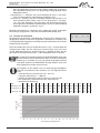
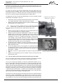
1
Bedienungsanleitung User’s Manual Manuel de l’utilisateur Abluftüberwachungseinheit mit Ventilator 2.00.320 HNA-18 II ATEX 2.00.320C HNA-18 II ATEX C DÜPERTHAL Sicherheitstechnik GmbH & Co. KG Frankenstr. 3 63791 Karlstein +49 6188 9139 0 +49 6188 9139 121 [email protected] http://www.dueperthal.com Inliegende deutsche Fassung der Anleitung ist der Urtext, welchen inliegende Übersetzungen wiedergeben. The German version of the manual enclosed herein is the original copy, reflected in both translations herein. La version allemande ci-après représente le texte original du manuel, rendu par les deux traductions ci-joint. Exhaust Airflow Unit with Fan Unité de contrôle du débit d'extraction d'air avec ventilateur Version Januar 2011 DÜPERTHAL Sicherheitstechnik GmbH & Co. KG Frankenstr. 3 63791 Karlstein, Deutschland Inhalt 1 1.1 1.2 2 2.1 2.2 2.3 3 3.1 3.2 3.2.1 3.2.2 3.2.3 3.2.4 3.2.5 3.2.6 3.3 3.4 3.5 3.6 4 5 6 Einleitung.............................................................................................................. 5 Bestimmungsgemäße Verwendung....................................................................... 5 Arbeitssicherheit.................................................................................................... 5 Montage der Einheit und Funktionsbeschreibung................................................. 5 Montage und Inbetriebnahme............................................................................... 5 Beschreibung der Elemente der Einheit................................................................ 6 Funktionsbeschreibung......................................................................................... 7 Betrieb................................................................................................................... 7 Normalbetrieb und Störungsanzeige..................................................................... 7 Einstellungen der Einheit...................................................................................... 7 Das Einstellmenü 1............................................................................................... 8 Einstellen von Datum und Uhrzeit......................................................................... 8 Wahl der Anzeigesprache..................................................................................... 8 Das Einstellmenü 2............................................................................................... 8 Einstellen der Lüfterdrehzahl................................................................................ 9 Anschluss eines Cool Line-Kühlschranks (nur bei Ausführung 2.00.320C)........ 10 Potenzialfreie Kontakte........................................................................................ 10 Einstellung des Differenzdrucks.......................................................................... 10 Akkubetrieb, Ein- und Ausschalten mit und ohne Akku....................................... 11 Protokollierung von Fehlern und Menüänderungen............................................ 12 Technische Daten................................................................................................ 12 Fehlersuche und ‑behebung............................................................................... 13 Kontaktinformationen.......................................................................................... 14 Version Januar 2011 Bedienungsanleitung 2.00.320 DE 3 DÜPERTHAL Sicherheitstechnik GmbH & Co. KG Frankenstr. 3 63791 Karlstein, Deutschland 4 DE Bedienungsanleitung 2.00.320 Version Januar 2011 DÜPERTHAL Sicherheitstechnik GmbH & Co. KG Frankenstr. 3 63791 Karlstein, Deutschland 1 Einleitung Sehr geehrter Kunde, Wir danken für das in unser Produkt gesetzte Vertrauen und wünschen Ihnen viel Erfolg und einen zufriedenen Arbeitsablauf. Bei der Entwicklung, Fertigung und Prüfung der ATEX-konformen Abluftüberwachungseinheit mit Ventilator haben wir größten Wert auf Betriebssicherheit und Benutzerfreundlichkeit gelegt. Die Einheit ist nach dem neusten Stand der Technik und nach anerkannten sicherheitstechnischen Regeln gefertigt und geprüft worden. 1.1 Bestimmungsgemäße Verwendung Die Abluftüberwachungseinheit mit Ventilator muss in EX-freien Bereichen aufgestellt werden und dient ausschließlich der Entlüftung durch Absaugung von Sicherheitsschränken im Innenbereich, Zone 2 für Gase der Temperaturklassen T1 - T4, Gasgruppe IIA oder Gasgruppe IIB. Das Produkt ist nur geeignet für Gasströme, die keine Partikel und Fremdstoffe transportieren. Die maximale Ansaugtemperatur beträgt 50°C. Es dürfen nur Stoffe abgesaugt werden, durch die die Saugmuffe aus PPs, der Saugschlauch aus PVC und der Ventilator nicht beeinträchtigt werden. Die entsprechende Stoffliste kann vom Hersteller in digitaler Form zur Verfügung gestellt werden. Jede Verwendung, die andersartig als das oben Beschriebene ist, ist verboten, kann zu gefährlichen Situationen, bis hin zur Lebensgefahr, Schäden an Anlage und Sachwerten führen und lässt Gewährleistung Vorsicht und Haftung für das Produkt seitens seines Herstellers und Vertreibers erlöschen. 1.2 Arbeitssicherheit Bei Montage und Betrieb sind die Technischen Regeln zur Lagerung brennbarer Flüssigkeiten, TRbF 20, Anhang L, die Norm EN 294 sowie alle anwendbaren gesetzlichen Vorschriften stets zu beachten. Das Produkt stellt bauartbedingt den Berührschutz für die Ventilatorflügel sicher. Veränderungen an Gehäuse oder Ansaug- und Abluftschlauch, durch die die Ventilatorflügel im Betrieb berührbar werden, sind verboten. Das Produkt darf nur fertig montiert, mit ordnungsgemäß angeschlossenem Ansaug- und Abluftschlauch in Betrieb genommen werden. Elektrische Arbeiten am Produkt dürfen nur vorgenommen werden, Vorsicht wenn die Abluftüberwachungseinheit zuvor stromlos geschaltet bzw. der Netzstecker gezogen wurde. Dasselbe gilt für elektrische Arbeiten am Abluftüberwachungssystem, zu dem die Einheit eventuell gehört. 2 Montage der Einheit und Funktionsbeschreibung 2.1 Montage und Inbetriebnahme 1. Schließen Sie, falls nötig oder gewünscht, die potenzialfreien Kontakte an der Klemmleiste an (vgl. Abschn. 3.3). 2. Schließen Sie die bauseitige Abluftanlage an: Verbinden Sie das vorhandene Entlüftungssystem spannungsfrei, z.B. mit einer flexiblen Manschette, mit der Einheit und dichten Sie die Verbindung mit einer passenden Schlauchschelle ab. Dies ist zwingend notwendig, um eine einwandfreie Funktion des Lüfters zu gewährleisten. Es ist hinsichtlich Version Januar 2011 Bedienungsanleitung 2.00.320 DE 5 DÜPERTHAL Sicherheitstechnik GmbH & Co. KG Frankenstr. 3 63791 Karlstein, Deutschland des Aufbaus der Anlage generell darauf zu achten, dass die Luftleitungen so kurz wie möglich sind. Vorsicht Keinesfalls darf die von der Überwachungseinheit abgesaugte Luft zurück in den Arbeitsraum geführt werden. 3. Schließen Sie die Abluftüberwachungseinheit an die Stromversorgung an. Warten Sie anschließend einige Augenblicke, bis die Überwachungseinheit initialisiert ist. 4. In manchen Fällen ist es notwendig, die Überwachungseinheit an die Gesamtanlage anzupassen. Dies erfordert im Wesentlichen die Einstellung des Differenzdruckmessers und/oder der Lüfterdrehzahl (siehe Abschn. 3.4). Vergegenwärtigen Sie sich, dass der erzielte Differenzdruck von der Lüfterdrehzahl abhängig ist. Wenn Sie die Berechtigung haben, die Lüfterdrehzahl neu einzustellen, dann achten Sie darauf, dass diese Hinweis Drehzahl und die eingestellte Differenzdruckschwelle aufeinander abgestimmt sind, um Fehlalarme zu vermeiden. 2.2 Beschreibung der Elemente der Einheit Vorderansicht Wo in dieser Anleitung auf die Betätigung der Pfeiltasten verwiesen wird, werden Pfeilsymbole verwendet: Taste NACH LINKS Taste NACH RECHTS Taste NACH OBEN Taste NACH UNTEN Anzeige- u. Bedienfeld auf Vorderseite Rückansicht Pfeil-/Cursortasten STOP/RESET- u. START/SET-Taste Anzeigebildschirm Druckseitiger Anschlussstutzen Optionale Anschlüsse Potenzialfreie Kontakte Steckdose für Kühlschrank (abgesichert mit 2 A) (nur in Ausführung 2.00.320 C; vgl. Abb. in Abschn. 3.2.6) Saugseitiges Staurohr mit Differenzdruckschalter/-messer Typenschild Ein/Aus-Schalter und Stromanschluss 6 DE Bedienungsanleitung 2.00.320 Version Januar 2011 DÜPERTHAL Sicherheitstechnik GmbH & Co. KG Frankenstr. 3 63791 Karlstein, Deutschland 2.3 Funktionsbeschreibung Nach Einschalten am Ein/Aus-Schalter wird die Luft des überwachten Objekts mittels des Lüfters im Gehäuseinnern der Überwachungseinheit über den saugseitigen Schlauch abgesaugt und über den druckseitigen Verbinder nach außen abgegeben (vgl. Abbildungen in Abschn. 2.2). Im Falle einer Störung, gleich aus welchem Grund, ist die Luftströmung im Kanal mehr oder weniger stark blockiert, wodurch der Differenzdruck, der im saugseitigen Staurohr gemessen wird, abfällt. Unterschreitet dabei der Differenzdruck den einstellbaren Schwellenwert, so wird akustisch und optisch Alarm ausgelöst. Im Falle einer Störung muss zunächst diese behoben werden, damit die Luft wieder ordnungsgemäß durch den Abluftkanal strömen kann. Danach sind die Störung und ihre Behebung, wie am Display angezeigt, zu quittieren, und zwar durch Drücken der START/SET-Taste. 3 Betrieb Vorsicht 3.1 Achten Sie bei Montage und Betrieb stets darauf, dass alle Bedingungen, die in Abschn. 1.1 und 1.2 genannt sind, erfüllt sind. Sonst setzen Sie sich gefährlichen Situationen aus. Normalbetrieb und Störungsanzeige Im Normalbetrieb erscheint nach dem Einschalten die sogenannte Hauptanzeige (vgl. Anzeige 1). In ihr werden Umgebungstemperatur, festgestellte Spannungsversorgung und Datum und Uhrzeit angezeigt. Bei Störung wird der festgestellte Fehler in der ersten Zeile des Displays angezeigt. Das Beispiel in Anzeige 2 weist auf fehlende oder zu schwache Spannungsversorgung hin. Weiter kann dort ein „Fehler Abluft“ erscheinen. Dieser weist auf eine andere, meist mechanische Beeinträchtigung des Strömungsflusses hin. Nach einer Störungsanzeige und der Behebung des Fehlers zeigt die Überwachungseinheit zwar an, dass der Abluftfluss wieder o.k. ist, aber die Störung und ihre Behebung müssen noch durch Drücken von START/SET quittiert werden (vgl. Anzeige 3). In regelmäßigen Intervallen ist der Lüfter auf Verschmutzungen, Beschädigungen und Korrosion zu überprüfen. Im Bedarfsfall ist er zu reinigen bzw. sind Mängel zu beseitigen, ggf. auch durch Einschicken Wichtig des Abluftaufsatzes an den Vertreiber bzw. Hersteller. 3.2 Abluft OK +23°C 15:43 231V 19.10.08 Anzeige 1 Fehler Spannungsver. +23°C 15:59 0V 19.10.08 Anzeige 2 Abluft OK Störung quittieren! +23°C 232V 16:06 19.10.08 Anzeige 3 Einstellungen der Einheit Durch gleichzeitiges Drücken der Pfeiltasten und werden die Einstellmenüs aufgerufen, mit denen die Einheit an die eigenen Gegebenheiten angepasst werden kann. Die 3 Einstellmenüs sind hierarchisch aufgebaut und jede höhere Ebene ist von der jeweils direkt niedrigeren zugänglich. Der Menüaufruf mit der obigen Tastenkombination oder von der jeweils hierarchieniedrigeren Ebene erfordert, dass der Benutzer einen Berechtigungscode eingibt. Die für den Anwender relevanten Einstelloptionen sind auf den unten beschriebenen beiden Menüebenen angesiedelt (Einstellmenü 1 und Einstellmenü 2). Zugang zum hierarchiehöchsten Menü, dem sogenannten Supervisor-Menü, wird nur geschultem Fachpersonal gewährt. Bei Aufruf eines Menüs erfolgt die Eingabe des für diese Ebene gültigen BerechVersion Januar 2011 Bedienungsanleitung 2.00.320 DE 7 DÜPERTHAL Sicherheitstechnik GmbH & Co. KG Frankenstr. 3 63791 Karlstein, Deutschland tigungscodes mit Hilfe der vier Pfeiltasten. Der Code muss nach der Eingabe durch Drücken der START/SET-Taste bestätigt werden. Der Berechtigungscode zum Aufruf des Einstellmenüs 1 ist 121. * EINGABE MENÜCODE * *** Mit den Pfeiltasten ñ, ò wird der gewünschte Konfigurationspunkt ausgewählt, mit der Pfeiltaste ð von „ein“ auf „aus“ geschaltet und umgekehrt bzw., bei einem symbolisierten Rechtspfeil „–>“ bei der Einstellung, ein Untermenü geöffnet (vgl. Anzeige 4b). Wenn ein Menü aufgerufen wird, aber keine weitere Aktivität geschieht, schließt sich das Menü automatisch nach etwa 1 Minute, ohne irgendeine Änderung zu speichern. Hinweis Wenn ein Menü offen war und automatisch oder vom Bediener geschlossen wurde, kann es ab Verlassen 20 Sekunden lang wieder aufgerufen werden, ohne dass der Berechtigungscode neu eingegeben werden muss. Anzeige 4a ** Einstellmenü 1 ** Einstellmenü 2 -> >Datum/Uhrzeit -> Sprache -> Anzeige 4b 3.2.1 Das Einstellmenü 1 Auf der Menüebene Einstellmenü 1 (vgl. Anzeige 4) lassen sich nach Eingabe des Berechtigungscodes 121 folgende Einstellungen vornehmen. „Einstellmenü 2 –> “ bedeutet, dass durch Betätigen der Taste ð die Menü ebene Einstellmenü 2 geöffnet wird, sofern der korrekte Berechtigungscode dieses Menüs eingegeben wird. „Datum/Uhrzeit –> “ bedeutet, dass durch Betätigen der Taste ð das Untermenü zum Stellen der Uhr und des Datums aufgerufen wird. „Sprache –> “ bedeutet, dass durch Betätigen der Taste ð das Untermenü zum Auswählen der Bedienersprache aufgerufen wird. Wurde das Einstellmenü 1 aufgerufen, dann werden die gerade angezeigten Einstellungen abgespeichert, wenn die Taste START/SET betätigt wird. ** Datum/Uhrzeit 19.10.08 ** 17:01 3.2.2 Einstellen von Datum und Uhrzeit Nach Wahl des Untermenüs „Datum/Uhrzeit“ erscheint das in Anzeige 5 wiedergegebene Display. Anzeige 5 Zum Einstellen von Uhrzeit und Datum wird der Cursor (Unterstreichung) mit den Tasten ï und ð zu den einzelnen Stellen bewegt. Jede Stelle wird durch Betätigen der Tasten ñ und ò verändert. Das eingestellte Datum bzw. die eingestellte Uhrzeit kann nicht in der Vergangenheit liegen. Mit der START/SET-Taste werden die Änderungen abgespeichert. 3.2.3 Wahl der Anzeigesprache Nach Wahl des Untermenüs „Sprache“ erscheint Anzeige 6, wobei die aktuell eingestellte Anzeigsprache durch den Hinweispfeil gekennzeichnet ist. Mit den Pfeiltasten und ò wird die gewünschte Sprache ausgewählt und mit der Taste START/SET die Auswahl abgespeichert. 3.2.4 Das Einstellmenü 2 Auf der von Einstellmenü 1 zugänglichen Ebene Einstellmenü 2 (vgl. Anzeige 7b) lassen sich folgende Einstellungen vornehmen. Der für diese Menüebene gültige Berechtigungscode ist 41531. Er wird bei Aufruf des Einstellmenüs 2 abgefragt. „Supervisor-Menü –> “ bedeutet, dass durch Betätigen der Taste ð die Menüebene Supervisor-Menü geöffnet wird; auf dieser Ebene können Systemeinstellungen vorgenommen werden, die im üblichen Betrieb des Geräts ohne Belang sind. Näheres kann beim Hersteller erfragt werden. „Überwachung Abluft ein“ bedeutet, dass Spannungsversorgung und Abluft überwacht werden, „aus“, dass zwar die Spannungsversorgung, nicht 8 DE Bedienungsanleitung 2.00.320 >Deutsch English Français Anzeige 6 * EINGABE MENÜCODE * ***** Anzeige 7a ** Einstellmenü 2 ** Supervisor-Menü -> Überw. Abluft ein >Lüfterdrehzahl -> Anzeige 7b Version Januar 2011 DÜPERTHAL Sicherheitstechnik GmbH & Co. KG Frankenstr. 3 63791 Karlstein, Deutschland aber der Abluftstrom überwacht wird. Folglich werden bei ausgeschalteter Abluftüberwachung auch nur Spannungsversorgungsfehler, keine Abluftfehler erkannt. „Lüfterdrehzahl –> “ bedeutet, dass durch Betätigen der Taste ð das Untermenü zum Einstellen der Lüfterdrehzahl aufgerufen wird. „Cool Line ein “ bedeutet, dass die rückseitige Steckdose geschaltet ist, um einen Kühlschrank der Reihe Cool Line mit Spannung zu versorgen, „aus“, dass die Steckdose nicht geschaltet, die Spannungsversorgung also abgestellt ist. (Steckdose und Menüoption sind nur in der Ausführung 2.00.320C verfügbar; vgl. Abschn. 3.2.6.) Wurde das Einstellmenü 2 aufgerufen, dann werden die gerade angezeigten Einstellungen abgespeichert, wenn die Taste START/SET betätigt wird. 3.2.5 Einstellen der Lüfterdrehzahl Nach Wahl des Untermenüs „Lüfterdrehzahl“ erscheint das in Anzeige 8 wiedergegebene Display. Die derzeit eingestellte Lüfterdrehzahl wird durch das Cursorpfeil-Symbol angegeben. Im Auslieferzustand ist die Einheit auf maximale Lüfterdrehzahl eingestellt. aus ├-┤ min 15 max ├-------------┤ ↑ Anzeige 8 Durch Verschieben des Cursors mit Hilfe der Tasten ï bzw. wird die Drehzahl verringert bzw. erhöht. Um den Lüfter ganz auszuschalten, muss bei Cursor auf der Minimum-Position ein weiteres Mal auf ï gedrückt werden. Um die gemachte Einstellung abzuspeichern, ist die START/SET-Taste zu drücken. Zur verbesserten Betriebssicherheit ist die STOP/RESET-Taste während der Änderung der Lüfterdrehzahl inaktiv, um jede versehentliche Änderung zu vermeiden. Es muss die gerade angezeigte Drehzahl Wichtig aktiv durch Drücken von START/SET bestätigt werden, damit man diesen Bildschirm wieder verlassen kann. Die Angaben in der Tabelle unten zu Strömungsgeschwindigkeit, Drehzahl und Volumenstrom beziehen sich auf folgende Anordnung: Hinweis • Innendurchmesser des Messrohrs D = 70,5 mm • Länge des Messrohres L = 1000 mm • Position des Messfühlers mittig in Bezug auf das Messrohr • kein Verbraucher (Sicherheitsschrank) angeschlossen • Ventilator ohne Belastung Stufe 0 1 2 3 4 5 6 7 8 9 10 11 12 13 14 15 0 Strömungsgeschw., m/s 0,0 900 1038 1176 1314 1446 1584 1722 1860 1998 2136 2274 2406 2544 2682 2820 1,5 1,8 2,0 2,2 2,6 2,7 3,0 3,2 3,4 3,8 4,2 4,4 4,7 4,9 5,1 Volumenstrom, m³/h 0 21 25 28 31 37 38 43 45 48 54 59 62 66 69 72 5 6 11 12 Volumenstrom m³/h Umdrehungen, 1/min 0 1 2 3 4 7 8 9 10 13 14 15 Einstellung Lüfterdrehzahl Version Januar 2011 Bedienungsanleitung 2.00.320 DE 9 DÜPERTHAL Sicherheitstechnik GmbH & Co. KG Frankenstr. 3 63791 Karlstein, Deutschland 3.2.6 Anschluss eines Cool Line-Kühlschranks (nur bei Ausführung 2.00.320C) Die eigens angepasste, rückseitig angebrachte Steckdose (vgl. nebenstehende Abbildung), die für den Anschluss eines Kühlschranks der Reihe Cool Line vorgesehen ist, kann mit der Option „Cool Line“ des Einstellmenüs 2 aktiviert und deaktiviert werden. Ist die Steckdose deaktiviert, ist ein angeschlossener Kühlschrank ausgeschaltet. Es erscheint in der Hauptanzeige der Hinweis „Cool Line deaktiviert“, und zwar alternierend in der ersten Zeile mit dem Zustandshinweis „Abluft OK“. Die zulässigen Anschlusswerte sind wie folgt: 230 V ~, 50 Hz, max. 1 A. Die Ausführung 2.00.320 C der Abluftüberwachungseinheit wird mit einem Adapterkabel (s. nebenstehende Abbildungen) für die spezielle Steckdose geliefert. Zum Anschluss des Lagerschranks Wichtig sind ausschließlich die vorhandene Dose und das Adapterkabel zu verwenden. Sobald ein Fehler auftritt, wird die Steckdose stromlos geschaltet, was dem Ausschalten des Kühlschranks gleichkommt. Dasselbe geschieht, wenn im Einstellmenü 2 die Abluftüberwachung ausWichtig geschaltet wird. Wenn die spezielle Steckdose hinten an der Abluftüberwachungseinheit aktiviert ist, fragt sie ab, ob ein Rücksignal vom angeschlossenen Schrank ankommt. Ist sie aktiv, empfängt aber Hinweis kein Rücksignal, erscheint die Meldung „Fehler Kühlschrank“ in der zweiten Zeile des Displays. 3.3 Potenzialfreie Kontakte Beim Auftreten einer Störung werden zwei potenzialfreie Schließerkontakte gesetzt, die an der Rückseite des Gehäuses zur individuellen Störanzeige am Klemmbrett abgegriffen werden können (s.u.). Das Rücksetzen der beiden Kontakte geschieht erst durch Quittierung etwaiger Störungsmeldungen mit der START/SET-Taste (vgl. Abschn. 3.1). 1 2 3 4 Vorbereitet für den Einbau eines mechanischen oder induktiven Endschalters 3.4 1 2 3 4 Potenzialfreie Kontakte Einstellung des Differenzdrucks Der im Staurohr erzeugte Differenzdruck wird mit dem auf dem Staurohr angebrachten Messgerät über die beiden transparenten Verbindungsschläuche erfasst. Er steigt entsprechend der Stärke des Luftstroms im saugseitigen Abluftschlauch. Wird der Luftstrom in irgendeiner Weise blockiert, so sinkt auch der Differenzdruck im Staurohr. Sinkt er unter die eingestellte Differenzdruckschwelle, so wird eine Störinformation über das Kabel im blauen Schutzschlauch zur weiteren Verarbeitung ins Gehäuseinnere geleitet. Aus technischen Gründen (Hysterese) liegt die Schwelle, bei der die Überwachungseinheit die Störinformation wieder revidiert, wenn der Differenzdruck wieder steigt, etwas oberhalb des Schwellenwertes, bei dem die Störung ausgelöst wurde. Es ist daher stets darauf zu achten, dass die Einstellungen für den Differenzdruck und 10 DE Bedienungsanleitung 2.00.320 Version Januar 2011 DÜPERTHAL Sicherheitstechnik GmbH & Co. KG Frankenstr. 3 63791 Karlstein, Deutschland die Lüfterdrehzahl so aufeinander abgestimmt sind, dass sowohl bei Störung ein Fehler ausgelöst wird als auch nach Beseitigung der Störungsursache der Fehler von der Einheit revidiert wird. Einen Schwellenwert für zu hohen Differenzdruck gibt es nicht. Der Schwellenwert für den Differenzdruck kann am Messgerät zwischen 20 Pa und 300 Pa eingestellt werden. Dazu muss lediglich die transparente Abdeckung entfernt und die Einstellung mit dem dafür vorgesehenen Schraubenzieherschlitz vorgenommen werden. Die bei Auslieferung eingestellte Differenzdruckschwelle beträgt 70 Pa. Folgende Schritte sind beim Einstellen der Differenzdruckschwelle zur Luftstromüberwachung zu vollziehen: Arretierungsclips zum Lösen der Kunststoffabdeckung 1. Schließen Sie die Abluftüberwachungseinheit ordnungsgemäß an der bauseitigen Abluftleitung (Abluftstutzen) an. 2. Stellen Sie den gewünschten Luftstrom der Lüftung ein (vgl. Abschn. 3.2.5). Bei einem Sicherheitsschrank für brennbare Flüssigkeiten muss der Luftstrom das Innenvolumen des Schrankes zehnVorsicht mal pro Stunde wechseln. 3. Lösen Sie die transparente Kunststoffabdeckung des Differenzdruckmessers an der Saugseite (vgl. nebenstehende Abbildung). 4. Stellen Sie den Differenzdruckmesser mit einem geeigneten Schraubenzieher mittels der Drehscheibe in der Mitte so ein (Differenzdruck erhöhen), dass im Display „Abluft OK“ angezeigt wird. Wird zu Beginn kein Fehler gezeigt, kann der Schwellenwert für den Differenzdruck reduziert werden, bis ein Fehler ausgelöst wird, und danach langsam wieder erhöht werden. Die Differenzdruckschwelle sollte nicht zu gering eingestellt sein, um die Fehlerhäufigkeit zu verringern. 5. Unterbrechen Sie den Abluftstrom kurz mit Hilfe der bauseitig vorhandenen Möglichkeiten (z.B. Verschließen der Abluftleitung mit der Hand). 6. Ist die Einstellung ordnungsgemäß, gibt die Einheit akustisch und durch Störungsmeldung auf dem Display Alarm. Nach aufgehobener Unterbrechung verstummt das akustische Warnsignal und „Störung quittieren“ erscheint auf dem Bildschirm. 7. Setzen Sie die Kunststoffabdeckung des Differenzdruckmessers wieder auf. 8. Quittieren Sie die Fehlermeldung durch Drücken der START/SET-Taste, um die potenzialfreien Kontakte wieder zu öffnen. 3.5 Drehscheibe zum Einstellen der Differenzdruckschwelle Akkubetrieb, Ein- und Ausschalten mit und ohne Akku Für den Fall eines Stromausfalls kann die Überwachungselektronik für eine Dauer von ca. 3 Stunden durch den integrierten Akkumulator weiter betrieben werden. Ist der Akkumulator ausreichend geladen, führt deshalb auch das Betätigen des Ein/Aus-Schalters nicht zum Ausschalten der Einheit. Nach dessen Betätigung versorgt sie der Akkumulator weiter mit Spannung. Um die Überwachungseinheit definitiv auszuschalten, d.h. von der Spannungsversorgung durch Netz und Akkumulator zu trennen, halten Sie, wenn die Hauptanzeige im Bildschirm zu sehen ist, die STOP/RESET-Taste ca. 5 Sekunden lang gedrückt. Es erscheint die Meldung „Bitte Gerät vom Netz trennen“. Leisten Sie dem Folge: Ausschalten am Ein/Aus-Schalter und Ziehen des Netzsteckers. Warten Sie einen kurzen Moment, bis das Gerät sich ausschaltet. Falls die Einheit ausgeschaltet wird, ohne zunächst die STOP/RESET-Taste Version Januar 2011 Bedienungsanleitung 2.00.320 DE 11 DÜPERTHAL Sicherheitstechnik GmbH & Co. KG Frankenstr. 3 63791 Karlstein, Deutschland gedrückt zu halten, kommt das einer Spannungsunterbrechung gleich. Es wird dann eine Fehlermeldung ausgelöst und die potenzialfreien Kontakte gesetzt (vgl. Abschn. 3.1 und 3.3). Sollte zum Ausschalten der Ein/Aus-Schalter betätigt worden sein, schaltet sich die Einheit durch nachheriges Gedrückt-Halten der STOP/RESET-Taste ebenfalls aus. Der durch den Schalter ausgelöste Fehler ist aber bei Wiedereinschalten zunächst zu quittieren. Ist der Ladezustand des Akkumulators ausreichend, kann die Einheit auch ohne Netzspannung eingeschaltet werden, und zwar durch Betätigen der START/ SET-Taste. Sollte die Akkuspannung unter den werksseitig eingestellten Wert fallen, schaltet die Überwachungseinheit sich automatisch aus. Auch das Einschalten und Betreiben der Einheit ohne Netzspannung führt zur Anzeige eines Spannungsversorgungsfehlers, der zu quittieren ist. 3.6 Protokollierung von Fehlern und Menüänderungen Störfälle und Änderungen der Einstellmenüs werden protokolliert und können durch Betätigen der Taste ï in der Hauptanzeige eingesehen werden (vgl. Anzeige 9). Durch die angezeigte Auflistung kann man sich mit den Pfeiltasten ñ und ò bewegen. Es werden maximal 50 Einträge gespeichert und chronologisch in der Liste angezeigt. Bei Überschreiten der maximalen Anzahl wird der älteste Eintrag überschrieben. Löschen der Protokolleinträge ist im Supervisor-Menü möglich. * Protokoll 018/42 * E1 22.06.08 13:32 >M 22.06.08 13:41-> E2 24.06.08 08:09 Anzeige 9 Ein solcher Protokolleintrag zeigt die Protokoll- bzw. Fehlerart, das Datum und die Uhrzeit an. In der Titelzeile der Liste wird angegeben, beim wievielten Protokoll man sich befindet (vor dem Schrägstrich) und wie viele insgesamt gespeichert sind (nach dem Schrägstrich). Wurde ein Fehler aufgezeichnet, wird der Fehlercode (E1 oder E2) angegeben. Die Fehlercodes haben dabei folgende Bedeutung: E1 Fehler Spannungsversorgung E2 Fehler Abluft Der Buchstabe „M“ kennzeichnet den Protokolleintrag einer Änderung der Einstellmenüs. Wie der symbolisierte Rechtspfeil anzeigt, kann bei Auswahl eines solchen Protokolleintrags durch Drücken der Pfeiltaste ð weitere Information aufgerufen werden. Diese Information besteht in einer Liste aller Konfigurationsoptionen der Einstellmenüs. Bei jeder Option wird vermerkt, ob sie sich bei der Änderung der Menüs, für die der Protokolleintrag steht, geändert hat oder nicht. Erst wenn die Einstellmenüs verlassen werden, wird ein Protokolleintrag aufgezeichnet, mit allen geänderten und ungeänderten Menüoptionen. Folgende Liste versinnbildlicht, wie die Menüänderungsprotokolle zu lesen sind. Datum/Uhr <> Datum/Uhrzeit nach Änderung ungleich vor Änderung Sprache = Spracheinstellung nach Änderung gleich vor Änderung Abl. Ueberw. 1->0 Die Einstellung für die Abluftüberwachung wurde von „ein“ (1) auf „aus“ (0) gestellt Drehzahl 12->9 Die Drehzahl wurde von Stufe 12 auf Stufe 9 verringert Cool Line 1->1 Die Einstellung für die Kühlschranksteckdose wurde auf „ein“ gelassen (nur 2.00.320C) Die Protokollierungsanzeige wird durch Drücken der STOP/RESET-Taste bzw. nach Ablauf einer kurzen Zeitdauer automatisch verlassen. 4 Technische Daten Anschlussspannung Frequenz Stromaufnahme 12 DE 230 V 50 Hz 0,16 A Bedienungsanleitung 2.00.320 Version Januar 2011 DÜPERTHAL Sicherheitstechnik GmbH & Co. KG Frankenstr. 3 63791 Karlstein, Deutschland Motorleistung Drehzahl Abluftgeschwindigkeit Volumenstrom Gewicht Abmessungen (ohne Anbauten) Schutzart ATEX-Kennung 5 37 W 900 - 2820 /min 1,5 - 5,1 m/s 21 - 72 m³/h ca. 7,5 kg 260 x 290 x 275 mm IP20 EX II (3) G [c II B T4] Fehlersuche und ‑behebung Beim Einsatz des Geräts können Störungen auftreten. Die folgende Tabelle hilft beim Auffinden der Ursache der Störung und ihrer Behebung. Kann eine Störung nicht auf eine der genannten Ursachen zurückgeführt werden oder führt die angegebene Behebung nicht zum Erfolg, so ist das Gerät außer Betrieb zu setzen und zur Überprüfung und Reparatur einzuschicken. Störung Gerät nicht in Betrieb mögliche Ursache Hauptschalter Netzkabel Absicherung rückwärtige Steckdose (CoolLine-Schrank) Überprüfung der Ursache · Ist das Gerät am Hauptschalter eingeschaltet? · Ist das Netzkabel beschädigt? · Ist das Netzkabel korrekt eingesteckt? · Sind die Sicherungen im Gerät in Ordnung? · Ist ein Verbraucher angeschlossen, der eventuell mehr als 1 A Strom aufnimmt? Behebung der Störung · Gerät am Hauptschalter einschalten. · Netzkabel gegen intaktes neues austauschen. · Netzkabel korrekt einstecken. · Sicherungen austauschen (2 x 1,25 A träge). · Diesen Verbraucher aus der Steckdose ziehen und die Sicherungen kontrollieren und ggf. austauschen (2 x 1,25 A träge). Lüfter in Betrieb, aber Displayelektrik/ Display ohne Funktion -elektronik · Störung vom Nutzer nicht behebbar. · Gerät zur Prüfung/Reparatur an Hersteller/Vertreiber einschicken. Display in Betrieb, aber Lüfter läuft nicht · Ist die Lüfterdrehzahl auf Stufe 0 eingestellt? · Lüfterdrehzahl auf höhere Stufe stellen (vgl. Abschn. 3.2.5). Fehler Netzspannung (E1) angezeigt Fehler Abluftstrom (E2) angezeigt Lüftereinstellung Mögliche Ursache, Überprüfung und Behebung wie unter „Gerät nicht in Betrieb“ oben. Saug- bzw. druck · Besteht im Ansaug- oder im Abförder seitiger Schlauch schlauch des Geräts ein Verschluss (Ver stopfung) oder starke Verschmutzung? Differenzdruck · Sind die Mess- und Verbindungsschläuche schalter an Muffe und Differenzdruckschalter angeschlossen? · Sind die Mess- und Verbindungsschläuche zwischen Muffe und Differenzdruck schalter beschädigt? · Sind die Mess- und Verbindungsschläuche zwischen Muffe und Differenzdruckschal ter zu den korrekten Anschlüssen gelegt? Version Januar 2011 · Mess- und Verbindungsschläuche muffenund schalterseitig anschließen. · Mess- und Verbindungsschläuche gegen intakte neue austauschen. Lüftereinstellung · Ist die Lüfterdrehzahl korrekt eingestellt? Schaltverstärker · Ist bei Auslösen des Differenzdruckschal ters ein klackendes Geräusch hörbar? · Schläuche korrekt anschließen: schrank seitiger Stutzen der Muffe zu P1 (+) des Schalters, geräteseitiger Stutzen der Muffe zu P2 (–) des Schalters. · Differenzdruckschalter öffnen und korrekt einstellen (vgl. Abschn. 3.4). · Spiralschlauch mit Hilfe der Schelle fest mit der Muffe verbinden. · Differenzdruckschalter öffnen und korrekt verkabeln: blaue Ader an 1, gelbe an 2, rote an 3. · Lüfterdrehzahl korrekt einstellen (vgl. Abschn. 3.2.5). · Gerät zur Überprüfung/Reparatur an Hersteller/Vertreiber einschicken. Einstellmenü 2 · Ist die Funktion zur Überwachung des Abluftstroms ausgeschaltet? · Ist der Differenzdruckschalter korrekt eingestellt? · Die Menüoption zur Abluftkontrolle auf „ein“ schalten (vgl. Abschn. 3.2.4). · Differenzdruckschalter öffnen und korrekt einstellen (vgl. Abschn. 3.4). · Ist der Differenzdruckschalter korrekt eingestellt? · Ist der Spiralschlauch fest mit der Muffe verbunden? · Ist die Verkabelung des Differenz druckschalters in Ordnung? Trotz Abluftstrom störung kein Abluftfehler (E2) angezeigt · Schlauch reinigen bzw. Verschluss/ Verstopfung entfernen. Differenzdruck schalter Bedienungsanleitung 2.00.320 DE 13 DÜPERTHAL Sicherheitstechnik GmbH & Co. KG Frankenstr. 3 63791 Karlstein, Deutschland 6 Kontaktinformationen Düperthal Sicherheitstechnik GmbH & Co. KG Frankenstr. 3 Tel.: +49 6188 9139 0 63791 Karlstein, Deutschland Fax: +49 6188 9139 121 Web: www.dueperthal.com E-mail: [email protected] Technische Änderungen an der Überwachungseinheit bleiben vorbehalten. Hinweis Gemäß der Richtlinie 2002/96/EG über Elektro- und Elektronik-Altgeräte (sogenannte WEEE-Richtlinie) nehmen wir von uns hergestellte bzw. in Verkehr gebrachte Altgeräte zurück. Um das exakte Verfahren abzustimmen, sprechen Sie uns unter der Anschrift oben an. Wir erklären weiterhin, dass die Geräte im Einklang mit der Richtlinie 2002/95/EG zur Beschränkung der Verwendung bestimmter gefährlicher Stoffe in Elektround Elektronikgeräten (sogenannte RoHS-Richtlinie) gefertigt sind. 14 DE Bedienungsanleitung 2.00.320 Version Januar 2011 DÜPERTHAL Sicherheitstechnik GmbH & Co. KG Frankenstr. 3 63791 Karlstein, Germany Contents 1 1.1 1.2 2 2.1 2.2 2.3 3 3.1 3.2 3.2.1 3.2.2 3.2.3 3.2.4 3.2.5 3.2.6 3.3 3.4 3.5 3.6 4 5 6 Introduction........................................................................................................... 5 Intended Use......................................................................................................... 5 Occupational Safety.............................................................................................. 5 Installing the Unit and Understanding its Functions.............................................. 5 Installing and Checking out................................................................................... 5 Monitoring Unit Components................................................................................. 6 Understanding Operation...................................................................................... 7 Operation............................................................................................................... 7 Normal Operation and Error Alert......................................................................... 7 Configuring the Settings........................................................................................ 7 The Configuration Menu 1.................................................................................... 8 Setting the Date and Time of Day......................................................................... 8 Selecting the Display Language............................................................................ 8 The Configuration Menu 2.................................................................................... 8 Setting the Speed of the Fan................................................................................. 9 Connecting a Cool Line Refrigerator (2.00.320C model version only)................ 10 Potential-free (“Dry”) Contacts............................................................................ 10 Setting the Pressure Offset................................................................................. 10 Operation on Battery, Switching on and off with and without Battery.................. 11 Error and Menu Change Reporting..................................................................... 12 Technical Specifications...................................................................................... 12 Troubleshooting................................................................................................... 13 Contact Details.................................................................................................... 14 Version January 2011 2.00.320 User’s Manual EN 3 DÜPERTHAL Sicherheitstechnik GmbH & Co. KG Frankenstr. 3 63791 Karlstein, Germany 4 EN 2.00.320 User’s Manual Version January 2011 DÜPERTHAL Sicherheitstechnik GmbH & Co. KG Frankenstr. 3 63791 Karlstein, Germany 1 Introduction Dear Customer: Thank you very much for purchasing our product. We are confident that it will meet your expectations and perform satisfactorily in your daily routines. The development, manufacture, and check of the ATEX-compliant exhaust airflow monitoring unit with fan has been guided by our concern to offer a device characterized by superior operation safety and user-friendliness. The unit was manufactured and checked according to state-of-the-art technology and widely recognized safety regulations. 1.1 Intended Use The exhaust air monitor with fan has to be used in EX-free areas and is intended exclusively for the positive extraction of exhaust air from safety cabinets for storage installed indoors, zone 2 for gases belonging to temperature classes T1 - T4, gas type IIA or gas type IIB. The product is suitable only for fluid flows not transporting any particles or foreign bodies. The maximum temperature of extracted medium is 50°C (122°F). Only such substances are acceptable for extraction that do not compromise the PPs connector sleeve, the PVC suction hose, and the fan. The relevant list of substances can be provided by the manufacturer in a digital format. Any and all uses other than the above-described is prohibited and may cause hazardous situations, potentially danger of death, damage to the system and material property, and will Caution cancel any and all warranty and liability for the product on the part of its manufacturer and distributor. 1.2 Occupational Safety The installation and operation of the product must be performed in compliance with Germany’s technical rules for the storage of flammable liquids, TRbF 20, Appendix L, the EN 294 standard, and all applicable international and national codes and standards. The design of the product is such that the fan blades are off-touch. Modifications to the enclosure or the suction and exhaust hoses that may make the fan blades accessible to the touch when the unit is in normal use are prohibited. The product must never be used if not totally installed, with properly set suction and exhaust hoses. Electrical work on the product must only be performed when the Caution exhaust air monitor was previously disconnected from power and/or locked against unwanted reapplication of power. This also holds for electrical work on the extraction system of which the monitor may be a part. 2 Installing the Unit and Understanding its Functions 2.1 Installing and Checking out 1. If needed or desired, connect the potential-free contacts (so-called “dry” contacts) to the terminal strip (see Sect. 3.3). 2. Connect the unit to the air extraction system on site: Connect the existing ventilation system to the unit, e.g., with a flexible sleeve fitting, making sure no strain is imposed on the connection, and make a tight connection using an appropriate hose clamp. This Version January 2011 2.00.320 User’s Manual EN 5 DÜPERTHAL Sicherheitstechnik GmbH & Co. KG Frankenstr. 3 63791 Karlstein, Germany is indispensable to ensure proper operation of the extraction fan. As a general rule, be sure that the system is set up with air lines that are as short as possible. In no circumstances, it is acceptable to transfer the air extracted by the blower fan back into the work room. Caution 3. Connect the exhaust airflow monitor to power. Then wait a few moments for the monitor to initialize. 4. In some cases, it may be necessary to adapt the monitor to the existing extraction system. This involves mainly setting the offset pressure meter and/or the speed of the fan (see Sect. 3.4). Info 2.2 Be aware that the actually existing pressure offset is directly dependent upon the speed with which the fan turns. Therefore, if you are authorized to change the fan speed, bear in mind that the fan speed and the pressure offset threshold have to be matched to each other. If this were not the case, there would be a risk of getting false alarms. Monitoring Unit Components Front View Where presses of the cursor keys a r e r e fe r e n c e d below in this manual, they are symbolized by arrow characters: Key LEFT Key RIGHT Key UP Key DOWN Display and Control Panel on Unit Front Back View Cursor/Arrow Keys STOP/RESET and START/SET Keys Display Screen Optional Connection Terminals Optional Connectors Potential-free (“dry”) Contacts Power Socket to Supply Refrigerator (protection at power supply: 2 amps) (2.00.320 C model version only; see photograph in Sect. 3.2.6) Suction Hose (Inlet) with Pressure Offset Switch/Meter Name Plate On/Off Switch and Power Supply Port 6 EN 2.00.320 User’s Manual Version January 2011 DÜPERTHAL Sicherheitstechnik GmbH & Co. KG Frankenstr. 3 63791 Karlstein, Germany 2.3 Understanding Operation After the On/Off switch was pressed to turn the unit on, the fan located inside the enclosure of the airflow monitor draws air from the monitored system through the suction hose connected to the inlet nipple and extracts the air from the system through the blower nipple on the enclosure (see Figures in Sect. 2.2). If an error condition develops, airflow through the line is restricted to a greater or lesser extent, and this causes the offset pressure measured in the suction hose to drop. If the offset pressure drops below the preset threshold, an audible alarm and a visual alarm are triggered. If an error condition occurs, first the problem has to be cleared to reenable proper airflow through the exhaust line. Then, as shown on the screen, the error and its correction have to be confirmed by pressing the START/SET key. 3 Operation Caution 3.1 Be sure that all provisions of Sect. 1.1 and 1.2 above are strictly complied with for both the installation and the operation. Failure to do so may expose you to hazardous situations. Normal Operation and Error Alert When it works normally, the unit shows the so-called standard display (see Display 1) after it was switched on. The standard display shows the outside temperature, the detected power supply, and the date and time. In case of an error condition, the reason for it is displayed. The example of Display 2 hints at a low voltage condition or power supply failure. An “Exhaust Air Error” may also be displayed. This error indicates another restriction, which is mechanical in most cases, of the flow of the fluid. After an error was cleared, the unit indicates that the exhaust airflow has returned to normal. Still, the error and its successful correction have yet to be confirmed by pressing the START/SET key (see Display 3). The fan has to be checked at regular intervals. If it is dirty, damaged or shows signs of corrosion, it has to be cleaned or the defects have to be corrected, if needed by returning the Important blower box for repair to the seller or manufacturer. 3.2 Configuring the Settings Exhaust Air OK +23°C 15:43 231V 19.10.08 Display 1 Power Supply Error +23°C 15:59 0V 19.10.08 Display 2 Exhaust Air OK Confirm error! +23°C 232V 16:06 19.10.08 Display 3 Pressing the ï and ð keys simultaneously opens the configuration menus of the exhaust airflow monitor in which its parameters can be adjusted to your particular ways of operating the unit. The 3 configuration menus are presented hierarchically and every level is accessible from the immediately lower level in the hierarchy. Whenever an operator wants to access one of the menu levels, either by using the above keypress combination or from the lower menu level, the airflow monitor requests entering an access code. The configuration options that are relevant for the operator are found on the two menu levels explained below (Configuration Menu 1 and Configuration Menu 2). Access to the hierarchically highest menu level, the so-called Supervisor Menu, is restricted to specifically trained technical staff. When a menu is accessed, the access code applicable to the menu level in question is entered using the four arrow keys. After its input, the code Version January 2011 2.00.320 User’s Manual EN 7 DÜPERTHAL Sicherheitstechnik GmbH & Co. KG Frankenstr. 3 63791 Karlstein, Germany has to be confirmed by pressing the START/SET key. The access code to access Configuration Menu 1 is 121. Use the ñ, ò arrow keys to select the desired configuration option. Use the ð arrow key to toggle between “on” and “off” for that configuration option or to access a sub-menu for options where a symbolized arrow “–>” is displayed (see Display 4b). Info If a menu was accessed but no further action performed, the menu closes again automatically after approx. 1 minute, and no change is saved to memory. If a menu was accessed and closed again, automatically or by the operator, it can be re-accessed without entering the access code again for 20 seconds after it was closed. * ENTER MENU CODE * *** Display 4a ** Config Menu 1 Config Menu 2 >Date/Time Language ** -> -> -> Display 4b 3.2.1 The Configuration Menu 1 At the level of Configuration Menu 1 (see Display 4), the following settings can be configured after the access code 121 was entered. “Configuration Menu 2 –> ” means that by pressing the ð key, the user can access the level of Configuration Menu 2, provided the access code corresponding to that menu level is entered. “Date/Time –> ” means that by pressing the ð key, the user can access a sub-menu for setting the date and the time of day. “Language –> ” means that by pressing the ð key, the user can access a sub-menu for selecting the display language. When the Configuration Menu 1 was accessed, the currently displayed settings are saved to memory by pressing the START/SET key. 3.2.2 Setting the Date and Time of Day When the “Date/Time” sub-menu was selected, the screen changes to the display reproduced in Display 5. *** Date/Time 19.10.08 *** 17:01 Display 5 The date and the time of day can be set using the cursor keys. Move the cursor (underline symbol) to the digit you want to change by pressing the ï and ð keys, change it by pressing the ñ and ò keys. The set date and the set time must not be in the past. Press the START/SET key to confirm and save your settings. 3.2.3 Selecting the Display Language When the “Language” sub-menu was selected, the screen changes to the display reproduced in Display 6, where the arrow symbol indicates the currently selected language. Use the arrow keys and ò to select the desired language for the display screen, and confirm your selection by pressing the START/SET key. 3.2.4 The Configuration Menu 2 At the level of Configuration Menu 2 (see Display 7b), which is accessible from Configuration Menu 1, the following settings can be configured. The access code required is 41531. It has to be entered when access to this menu is requested. “Supervisor Menu –> ” means that by pressing the ð key, the user can access the level of Supervisor Menu, which contains system parameters that are unimportant for standard operation. Please contact the manufacturer for further information on this matter. “Exhaust Monitor on” means that both power supply and airflow are monitored, “off” that only the power supply is monitored, no monitor8 EN 2.00.320 User’s Manual Deutsch >English Français Display 6 * ENTER MENU CODE * ***** Display 7a ** Config Menu 2 ** Supervisor Menu -> Exhaust Monitor on >Fan Speed -> Display 7b Version January 2011 DÜPERTHAL Sicherheitstechnik GmbH & Co. KG Frankenstr. 3 63791 Karlstein, Germany ing of extraction flow takes place. Accordingly, when exhaust airflow monitoring is off, only power supply errors will be detected. “Fan Speed –> ” means that by pressing the ð key, the user can access a sub-menu for setting the speed at which the fan should turn. “Cool Line on” means that the power socket at the back of the enclosure, which can power a Cool Line refrigerator cabinet, is switched on, “off” that the socket is dead and, hence, power to the refrigerator is switched off. (The power socket and this menu option are available only on units of the 2.00.320C model version; see Sect. 3.2.6.) When the Configuration Menu 2 was accessed, the currently displayed settings are saved to memory by pressing the START/SET key. 3.2.5 Setting the Speed of the Fan When the “Fan Speed” sub-menu was selected, the screen changes to the display reproduced in Display 8. The currently set speed of the fan is indicated by the cursor arrow sign. When it is shipped ex works, the unit is set to maximum fan speed. off ├-┤ min 15 max ├-------------┤ ↑ Display 8 Press the ï or key to move the cursor to the left or the right, thereby reducing or increasing the fan speed. To turn the fan off, move the cursor once more to the left, pressing the ï key, when it is on the minimum position. To set the new speed, press the START/SET key. For increased safety, the STOP/RESET key is disabled while a modification of the fan speed setting is in progress, in order to avoid any inadvertent change. You will have to positively Important confirm the currently displayed value by pressing START/SET, to be able to quit this input screen. Info The information on fluid velocity, fan speed, and volume flow rate in the table below relate to the following setup: • Inside diameter of measuring tube D = 70.5 mm • Length of measuring tube L = 1000 mm • Position of sensor centric relative to measuring tube • No power-comsuming device (safety cabinet) connected • Fan not subjected to any strain or load Level 0 1 2 3 4 5 6 7 8 9 10 11 12 13 14 15 0 Fluid Velocity, m/s 0.0 900 1038 1176 1314 1446 1584 1722 1860 1998 2136 2274 2406 2544 2682 2820 1.5 1.8 2.0 2.2 2.6 2.7 3.0 3.2 3.4 3.8 4.2 4.4 4.7 4.9 5.1 Volume Flow Rate, m³/h 0 21 25 28 31 37 38 43 45 48 54 59 62 66 69 72 Volume Flow Rate m³/h Revolutions, 1/min 0 1 2 3 4 5 6 7 8 9 10 11 12 13 14 15 Fan Speed Setting Version January 2011 2.00.320 User’s Manual EN 9 DÜPERTHAL Sicherheitstechnik GmbH & Co. KG Frankenstr. 3 63791 Karlstein, Germany 3.2.6 Connecting a Cool Line Refrigerator (2.00.320C model version only) The custom-designed power socket at the back of the enclosure (see the photograph to the right), which is designed for connecting a Cool Line series refrigerator to the unit, can be enabled or disabled with the “Cool Line” option of Configuration Menu 2. When it is disabled, the refrigerator is switched off and there is a “Cool Line disabled” message on the standard display, alternating with the status message “Exhaust Air OK” on the first line. Acceptable specifications of a refrigerator are 230 V AC, 50 Hz, max. 1 A. The 2.00.320 C model version of the exhaust air control unit ships with a dedicated adapter cable matched to the customdesigned power socket (see the photographs to the right). Important Power may be supplied to the cabinet exclusively with the factory-installed socket and shipped, dedicated cable. As soon as an error condition is detected, power to the power socket is switched off, which is equivalent to turning the refrigerator off. The same holds when the exhaust air Important monitoring is disabled in the Configuration Menu 2. Info 3.3 When enabled, the special power socket at the back of the exhaust air control unit checks whether it receives a loop-back signal from the connected storage cabinet. If it is enabled, but does not detect a loop-back signal, a message “Error Cool Line” is displayed at the second line of the screen. Potential-free (“Dry”) Contacts An error condition causes two normally open, potential-free contacts to be closed; for individually locating errors, their closure can be recorded at the switching panel from the backside of the enclosure (see below). Confirming the error and its correction by pressing the START/SET key (see Sect. 3.1) causes the two contacts to be reset (i.e., opened). 1 2 3 4 Prepared for the Installation of a Mechanical or Inductive Position Switch 3.4 1 2 3 4 Potential-free “Dry” Contacts Setting the Pressure Offset The pressure offset found in the suction line is recorded via the two transparent sensor tubes by a pressure meter sitting on the line. It rises as the airflow through the suction-side extraction line increases. As soon as the airflow is restricted or blocked, the pressure offset recorded at the inlet drops. If it drops below the preset threshold, a signal that an error condition has developed is sent into the enclosure for further processing via the cable in the blue protective conduit. For technical reasons (hysteresis), the threshold from which the monitor cancels the error condition when the pressure offset rises again, is a little higher than the threshold that triggers an error. Therefore, make sure at all times that the settings for the pressure offset and for the fan speed are matched to each other in 10 EN 2.00.320 User’s Manual Version January 2011 DÜPERTHAL Sicherheitstechnik GmbH & Co. KG Frankenstr. 3 63791 Karlstein, Germany such a way that both an error is indicated when a restriction is detected, and the error is canceled by the unit when the restriction is cleared. There is no upper threshold for a maximum pressure offset. The value of the pressure offset threshold can be set at the meter from 20 Pa to 300 Pa. This is done by simply removing the transparent cover and using a screwdriver in the provided slot to turn the selector. The factory-set default threshold of the pressure offset is 70 Pa. Setting the pressure offset threshold for monitoring the airflow requires the following steps: Latch clips to hold/remove the plastic cover 1. Connect the exhaust air monitor properly to the extraction system (outlet nipple) on site. 2. Set the fan speed to the desired extraction airflow (see Sect. 3.2.5). In a cabinet for flammable liquids, the extraction airflow has to be sufficient to replace the interior volume of the Caution cabinet 10 times every hour. 3. Loosen the plastic cover of the pressure offset meter sitting on the suction hose (refer to the photograph to the right). 4. Using an appropriate screwdriver in the turning selector at the center of the pressure offset meter, set the offset threshold to make “Exhaust OK” appear on the screen (increase pressure offset). If no error is displayed on the screen when you start, the pressure offset setting may first be reduced until an error is displayed, then slowly increased again. The pressure offset threshold triggering an error should not be too low, so as to avoid frequent errors. 5. Using appropriate means on site (e.g. by covering the exhaust outlet with your hand), interrupt the extraction airflow temporarily. 6. If set correctly, the unit will trigger the audible alarm and display the error message on the screen. After the airflow interruption is cleared, the audible alarm should stop and the “Confirm error” message should appear on the screen. 7. Reinstall the plastic cover on the pressure offset meter. 8. Confirm the error message on the screen by pressing the START/ SET key to re-open the dry contacts. 3.5 Selector for setting the pressure offset threshold Operation on Battery, Switching on and off with and without Battery In the event of power supply failure, the control unit can be operated on the internal battery (accumulator) for approx. 3 hours. This is why, provided the battery is sufficiently charged, pressing the On/ Off switch will not turn the unit off. When the switch was pressed, the battery will continue to supply power to it. To turn the monitor off definitely, i.e. to disconnect power to it from both the mains network and the battery, hold down the STOP/RESET key for approx. 5 seconds when the standard display shows on the screen. This causes the message “Please disconnect power to unit!” to appear. Do as you are asked to: switch the monitor off using the On/Off switch and unplug the mains plug. Wait a short time for the monitor to switch itself off. If the unit is switched off without holding down the STOP/RESET key first, this counts as a power supply failure. It will trigger an error message and close the dry contacts (see Sect. 3.1 and 3.3). In case the On/Off switch Version January 2011 2.00.320 User’s Manual EN 11 DÜPERTHAL Sicherheitstechnik GmbH & Co. KG Frankenstr. 3 63791 Karlstein, Germany was pressed first, the monitor will indeed switch itself off when the STOP/ RESET key is then held down. However, the error message that this will cause has to be confirmed when it is switched on again. If the battery is charged to a sufficient level. it is possible to switch the unit on while it is not connected to mains power, by pressing the START/ SET key. If the battery voltage drops below a factory-set threshold, the monitor switches itself off automatically. Turning on and operating the module without mains power will trigger a power supply error message as well, which will have to be confirmed. 3.6 Error and Menu Change Reporting Error conditions and changes applied to the configuration menus are recorded and saved to memory. They can be viewed after pressing the ï arrow key in the standard display (see Display 9). You can scroll through the displayed listing by pressing the ñ and ò arrow keys. The maximum number of entries saved to memory and displayed in this listing in chronological order is 50. When the maximum number is reached, any further report will overwrite the oldest one in memory. Deleting the entries in memory is possible from the Supervisor Menu. * Report 018/42 * E1 22.06.08 13:32 >M 22.06.08 13:41-> E2 24.06.08 08:09 Display 9 A report entry contains information on the type of entry, i.e. error or menu change, the date, and the time of day. The title line of the listing shows the number of the report currently looked at (before the slash) and the total number of entries in memory (after the slash). If the entry is an error report, the error code (E1 or E2) is shown. These error codes have the following meaning: E1 Power Supply Error E2 Exhaust Air Error The letter “M” stands for the report of a modification of the configuration menus. As is indicated by the symbolized arrow to the right, pressing the ð arrow key, when this entry is selected, will show additional information. This information is a list of all settings of the configuration menus. All the options are given with the indication of their status, changed or unchanged at the moment the modification record was generated. The record for a modification is generated only when the operator quits the configuration menus, and it includes all settings, whether changed at that point in time or remained as is. The following overview is meant to assist you in interpreting the change reports. Date/Time <> Date/time before do not equal after change Language = Set language before equals after change Exh Monitor1->0 The exhaust monitoring setting was set from “on” (1) to “off” (2) Speed 12->9Fan speed was changed from level 12 to level 9 Cool Line 1->1 The setting for the refrigerator socket was left at “on” (with 2.00.320C models only) The report screen is quit by pressing the STOP/RESET key, or it returns automatically to the standard display after a short time of inactivity. 4 Technical Specifications Power Supply Voltage Frequency Current Rating Motor Power 12 EN 230 V 50 Hz 0.16 A 37 W 2.00.320 User’s Manual Version January 2011 DÜPERTHAL Sicherheitstechnik GmbH & Co. KG Frankenstr. 3 63791 Karlstein, Germany Revolutions 900 - 2820 /min Fluid Velocity 1.5 - 5.1 m/s Volume Flow Rate 21 - 72 m³/h Weight approx. 7.5 kg Dimensions (enclosure edges) 260 x 290 x 275 mm Ingress Protection IP20 ATEX Rating EX II (3) G [c II B T4] 5 Troubleshooting In the course of using the appliance, malfunctions may occur. The table below is meant to help troubleshoot and correct malfunctions. If a malfunction cannot be traced to one of the possible causes or the correction given does not solve the issue, then use of the appliance has to be discontinued and it has to be returned for inspection and repair. Malfunction Appliance does not run Possible Cause On/Off Switch Power Supply Cord Overvoltage Switch Power Socket at the Back (Cool Line cabinet) Fan runs, but display screen does not work Display Electrics/ Electronics Display screen works, Fan Speed but fan does not run Setting Power Supply Error (E1) shows on screen Verification of Cause Correction of Malfunction · Is the appliance switched on at the On/Off switch? · Is the power supply cord damaged? · Is the power supply cord properly connected? · Are the fuses inside the appliance o.k.? · Switch the appliance on at the On/Off switch. · Replace the supply cord with a new one. · Connect the supply cord to the intended socket. · Replace the fuses (2 x 1.25 A slow blow). · Is a device connected that may consume current at more than1 A? · Disconnect this device from the socket and check the fuses and replace them as needed (2 x 1.25 A slow blow). · Malfunction cannot be corrected by user. · Return the appliance to the manufacturer/ seller for inspection/repair. · Is the fan speed set to level 0? · Set the fan speed to a higher level (see Sect. 3.2.5). Possible Cause, Verification, and Correction as under “Appliance does not run” above. Exhaust Airflow Error Inlet or Outlet (E2) shows on screen Hose Pressure Offset Meter/Switch · Is the suction or the extraction hose of the appliance blocked (airflow restriction) or very dirty? · Are the measuring tubes connecting the sleeve to the meter/switch properly connected? · Are the measuring tubes connecting the sleeve to the meter/switch damaged? · Are the measuring tubes connecting the sleeve to the meter/switch connected to the correct nipples? Fan Speed Setting Switching Amplifier · Is the fan speed set correctly? · Is a clapping noise heard when the pressure offset switch cuts in or out? · Connect the measuring and connecting tubes to both the meter/switch and the sleeve in the extraction line. · Replace the measuring and connecting tubes with new ones. · Connect the tubes as intended: nipple closer to the cabinet of the sleeve to P1 (+) of the meter/switch, nipple closer to the appliance of the sleeve to P2 (–) of the meter/switch. · Open the pressure offset meter/switch and set it properly (see Sect. 3.4). · Tightly set the spiral hose onto the sleeve using the clamp. · Open the pressure offset meter/switch and wire it correctly: blue wire to 1, yellow to 2, red to 3. · Set the fan speed correctly (see Sect. 3.2.5). · Return the appliance to the manufacturer/ seller for inspection/repair. Configuration Menu 2 Pressure Offset Meter/Switch · Is the feature for monitoring the extraction airflow turned off? · Is the pressure offset meter/switch properly set? · Set the menu option for the exhaust airflow monitor to “on”. · Open the pressure offset meter/switch and set it properly (see Sect. 3.4). · Is the pressure offset meter/switch properly set? · Is the spiral hose connected tightly to the sleeve? · Is the pressure offset meter/switch wired properly? Despite irregular extraction airflow no airflow error (E2) on screen Version January 2011 · Clean the hose and/or clear the restriction. 2.00.320 User’s Manual EN 13 DÜPERTHAL Sicherheitstechnik GmbH & Co. KG Frankenstr. 3 63791 Karlstein, Germany 6 Contact Details Düperthal Sicherheitstechnik GmbH & Co. KG Frankenstr. 3 Tel.: +49 6188 9139 0 63791 Karlstein, Germany Fax: +49 6188 9139 121 Web: www.dueperthal.com E-mail: [email protected] We reserve the right to change technical specs of the unit without prior notice. Info Pursuant to the directive 2002/96/EC on Waste Electrical and Electronic Equipment (so-called WEEE Directive), equipment that was manufactured or distributed by ourselves may be returned to us. To discuss the exact procedure we will follow, please contact us with the details above. We also declare that the equipment manufacture conforms to the directive 2002/95/EC on the restriction of the use of certain hazardous substances in electrical and electronic equipment (so-called RoHS Directive). 14 EN 2.00.320 User’s Manual Version January 2011 DÜPERTHAL Sicherheitstechnik GmbH & Co. KG Frankenstr. 3 63791 Karlstein, Allemagne Table des matières 1 1.1 1.2 2 2.1 2.2 2.3 3 3.1 3.2 3.2.1 3.2.2 3.2.3 3.2.4 3.2.5 3.2.6 3.3 3.4 3.5 3.6 4 5 6 Introduction........................................................................................................... 5 Usage prévu.......................................................................................................... 5 Sécurité au travail.................................................................................................. 5 Montage de l'unité et description de son fonctionnement..................................... 5 Montage et mise en route..................................................................................... 5 Descriptif de l’unité................................................................................................ 6 Principe de fonctionnement................................................................................... 7 Fonctionnement..................................................................................................... 7 Fonctionnement normal et alarme d'erreur........................................................... 7 Réglages de l'unité................................................................................................ 7 Le Menu de réglages 1.......................................................................................... 8 Réglage de la date et de l'heure........................................................................... 8 Choix de la langue d’affichage.............................................................................. 8 Le Menu de réglages 2.......................................................................................... 8 Réglage de la vitesse du ventilateur..................................................................... 9 Raccordement d'une armoire Cool Line (modèle 2.00.320C seulement)........... 10 Contacts secs « en l'air ».................................................................................... 10 Réglage de la pression différentielle................................................................... 10 Pile de secours, mise sous tension et arrêt avec et sans pile............................. 11 Rapports d'erreur et de modification du menu.................................................... 12 Fiche technique................................................................................................... 12 Dépannage.......................................................................................................... 13 Coordonnées de contact..................................................................................... 14 Version Janvier 2011 Manuel de l’utilisateur 2.00.320 FR 3 DÜPERTHAL Sicherheitstechnik GmbH & Co. KG Frankenstr. 3 63791 Karlstein, Allemagne 4 FR Manuel de l’utilisateur 2.00.320 Version Janvier 2011 DÜPERTHAL Sicherheitstechnik GmbH & Co. KG Frankenstr. 3 63791 Karlstein, Allemagne 1 Introduction Cher Client, Nous vous remercions de l’achat de notre produit et de la confiance que vous nous témoignez ainsi. Nous souhaitons qu’il vous donne entière satisfaction. Le développement, la fabrication et les vérifications de l’unité de contrôle du débit d’extraction d’air avec ventilateur, compatible ATEX ont été menés en portant une attention particulière à la sécurité de fonctionnement et à la facilité d’utilisation de l’unité. Elle a été fabriquée et sa conformité a été vérifiée en tenant compte des dernières évolutions technologiques et des standards de sécurité reconnus. 1.1 Usage prévu L’unité de contrôle du débit d’extraction d’air avec ventilateur doit être mise en place dans des zones non-EX et sert exclusivement à la ventilation par extraction d’air des armoires de sécurité pour le stockage mises en place à l’intérieur, zone 2 pour les gaz des catégories de température T1 - T4, groupe IIA ou groupe IIB. Le produit n’est adapté qu’aux fluides gazeux ne contenant ni particules ni corps étrangers. La température maximale d’aspiration est de 50°C. L’extraction ne sera réalisée que pour des substances qui ne dégradent pas le raccord d’extraction en PPs ni le tuyau d’aspiration en PVC, ni le ventilateur. La liste des substances acceptables peut être fournie, au format numérique, par le fabricant. Tout usage d’une autre nature que ce qui vient d’être exposé est interdit, peut provoquer des situations dangereuses, y compris le danger de mort, des dommages subis par l’appareil et des matériels Attention voisins et rend caduque toute garantie et responsabilité assumée pour le produit par le fabricant et le distributeur. 1.2 Sécurité au travail Le montage et la manipulation de l’unité doivent obéir impérativement aux dispositions des règles techniques allemandes relatives au stockage des liquides inflammables, TRbF 20, Annexe L, à la norme EN 294 et à tous les règlements pertinents internationaux et nationaux. Le produit assure, par sa conception, qu’il est impossible de toucher les pales du ventilateur. Toute modification du boîtier et des tuyaux d’aspiration et de refoulement qui rendrait accessibles au toucher les pales du ventilateur pendant le fonctionnement normal, est interdite. Il est impératif de ne mettre le produit en service qu’après qu’il est totalement monté et que les tuyaux d’aspiration et de refoulement sont correctement raccordés. Attention Des interventions électriques sur le produit ne doivent être réalisées qu’après que le produit a été débranché et/ou verrouillé pour éviter l’application intempestive d’électricité. La même chose est vraie des interventions électriques sur le système d’extraction d’air dont l’unité fait éventuellement partie. 2 Montage de l'unité et description de son fonctionnement 2.1 Montage et mise en route 1. Si nécessaire ou souhaité, relier les contacts secs (contacts de borne « en l’air ») au bornier (voir la section 3.3). 2. Raccorder l’unité sur le système d’extraction existant sur place : Relier le système d’extraction sur place à l’unité, par exemple au moyen d’un manchon souple, sans que la connexion soit soumise à une traction, Version Janvier 2011 Manuel de l’utilisateur 2.00.320 FR 5 DÜPERTHAL Sicherheitstechnik GmbH & Co. KG Frankenstr. 3 63791 Karlstein, Allemagne et réaliser un raccordement étanche à l’aide d’un collier de tuyau adapté. Cela est incontournable pour assurer le fonctionnement correct du ventilateur. De manière générale, veiller à ce que les canalisations d’air soient aussi courtes que possibles. Il est absolument interdit de diriger l’air vicié extrait par le boîtier dans la zone de travail. Attention 3. Relier l’unité de contrôle du débit d’extraction d’air à l’alimentation secteur. Puis attendre quelques instants jusqu’à ce que l’unité soit initialisée. 4. Dans quelques cas, il est nécessaire d’adapter l’unité de contrôle au système de ventilation existant. Avant tout, il s’agit là de régler le capteur de pression différentielle et/ou la vitesse du ventilateur (voir à la section 3.4). Info Garder à l’esprit que le différentiel de la pression dépend directement de la vitesse à laquelle le ventilateur tourne. Il est donc de rigueur d’adapter l’une à l’autre la vitesse du ventilateur et le seuil de pression différentiel qui déclenche une erreur. Si cela n’était pas fait, il risque d’y avoir de fausses alertes. Vue de face Lorsque ci-dessous, dans le présent manuel, des actions sur les touches curseurs sont signalées, cela se fait par des flèches symbolisées : Touche À GAUCHE Touche À DROITE Touche EN HAUT Touche EN BAS Panneau d'affichage et de commande sur la façade 2.2 Descriptif de l’unité Vue de dos Touches flèches/curseurs Touches STOP/RESET et START/SET Écran d'affichage Raccord côté refoulement Connecteurs en option Contacts secs (« en l'air ») Prise électrique pour armoire (protection côté alimentation : 2 A) (modèle 2.00.320 C seulement ; cf. la photo à la section 3.2.6) Tuyau côté aspiration avec capteur/ interrupteur de pression différentielle Plaque nominative Interrupteur principal et prise d'alimentation 6 FR Manuel de l’utilisateur 2.00.320 Version Janvier 2011 DÜPERTHAL Sicherheitstechnik GmbH & Co. KG Frankenstr. 3 63791 Karlstein, Allemagne 2.3 Principe de fonctionnement Après que l’unité a été démarrée à l’aide de l’interrupteur principal, le ventilateur dans le boîtier de l’unité de contrôle du débit aspire l’air dans les objets surveillés à travers le manchon d’entrée, puis refoule cet air à l’extérieur par le raccord de sortie sur le boîtier (voir les figures à la section 2.2). En cas de dysfonctionnement, quelle qu’en soit l’origine, le débit d’air par la ligne d’extraction est gêné de façon plus ou moins importante, ce qui provoque une chute de la pression différentielle mesurée dans le tuyau d’aspiration. Si celle-ci baisse en dessous du seuil prédéfini, une alarme sonore et une alarme visible se déclenchent. En cas d’une erreur de fonctionnement, il faut d’abord dépanner le problème afin que le débit d’air normal par la ligne d’extraction soit rétabli. Ensuite, comme l’écran vous le demande, il faut valider l’erreur et sa correction réussie en appuyant sur la touche START/SET. 3 Fonctionnement Attention 3.1 Pour le montage et le fonctionnement, s’assurer que toutes les dispositions données aux sections 1.1 et 1.2 sont impérativement respectées. À défaut, on s’expose à des situations dangereuses. Fonctionnement normal et alarme d'erreur Quand l’unité fonctionne normalement, ce qui est appelé l’écran normal (cf. l’Écran 1) s’affiche après la mise sous tension. L’écran normal renseigne de la température ambiante, de l’alimentation constatée et des date et heure. Suite à un dysfonctionnement, l’erreur qui l’a provoqué s’affiche à l’écran. L’exemple de l’Écran 2 signale une alimentation électrique faible ou coupée. Il est possible aussi qu’une « Erreur débit d’air » s’affiche. Celle-ci signale une autre restriction, généralement mécanique, du débit du fluide. Débit d'air OK +23°C 15:43 231V 19.10.08 Écran 1 Erreur alim. secteur Après qu’une erreur de fonctionnement vient d’être corrigée, l’unité affiche que le débit de l’air d’extraction s’est rétabli à la normale. Néanmoins, il faut encore valider le dysfonctionnement et sa correction en appuyant sur la touche START/SET (cf. l’Écran 3). +23°C 15:59 À intervalles réguliers, il faut contrôler si le ventilateur s’est sali, est endommagé ou corrodé. Au besoin il faut le nettoyer ou corriger les défauts, le cas échéant en retournant le boîtier à son vendeur ou Important fabricant pour remise en état. Débit d'air OK Valider l'erreur! +23°C 232V 16:06 19.10.08 3.2 0V 19.10.08 Écran 2 Écran 3 Réglages de l'unité En appuyant simultanément sur les touches flèches ï et ð, on accède aux menus des réglages de l’unité de contrôle du débit d’extraction d’air. Ceux-ci permettent de l’adapter au mieux à vos besoins spécifiques. Les 3 menus des réglages qui existent se présentent sous forme d’une hiérarchie, au sein de laquelle chaque niveau est accessible depuis le menu du niveau directement inférieur. Lorsque l’ouvrier veut accéder à un des menus, soit par l’action sur les touches signalée ci-dessus, soit depuis le niveau de menu inférieur, l’unité lui demande un code d’autorisation. Les réglages qui importent à l’utilisation sont disponibles aux deux niveaux de menu expliqués ci-dessous (Menu de réglages 1 et Menu de réglages 2). L’accès au niveau de menu les plus élevé, dit Menu superviseur, est réservé aux personnels spécialisés correctement formés. Lorsqu’un menu doit être affiché, la saisie du code correspondant au niveau de Version Janvier 2011 Manuel de l’utilisateur 2.00.320 FR 7 DÜPERTHAL Sicherheitstechnik GmbH & Co. KG Frankenstr. 3 63791 Karlstein, Allemagne menu en question se fait au moyen des quatre touches flèches. Après sa saisie, le code d’accès rentré doit être validé par une action sur la touche START/SET. Le code donnant accès au Menu de réglages 1 est 121. * SAISIE CODE MENU * *** Une option de configuration peut être sélectionnée à l’aide des touches ñ et ò. Pour passer l’option sélectionnéede de Oui à Non ou vice versa, ou accéder à un sous-menu, si une flèche symbolisée « –> » y figure, appuyer sur la touche ð (voir l’Écran 4b). Info Si n’importe lequel des menus est ouvert, mais qu’aucune action ultérieure s’effectue, ce menu se referme automatiquement au bout de 1 minute environ d’inactivité, sans enregistrer aucune modification. Lorsqu’un menu se referme, soit automatiquement, soit par l’utilisateur, il est possible de l’ouvrir de nouveau sans saisir le code d’accès, si on le rouvre dans les 20 secondes après sa fermeture. Écran 4a * Menu Réglages 1 * Menu Réglages 2 -> >Date/Heure -> Langue -> Écran 4b 3.2.1 Le Menu de réglages 1 Au niveau du Menu de réglages 1 (cf. l’Écran 4), les options suivantes peuvent être paramétrées après que le code d’accès 121 a été rentré. « Menu de réglages 2 –> » : l’action sur la touche ð ouvre le niveau Menu de réglages 2, moyennant le code d’accès correspondant. « Date/Heure –> » : l’action sur la touche ð ouvre un sous-menu qui permet de régler la date et l’heure. « Langue –> » : l’action sur la touche ð ouvre un sous-menu qui permet de choisir la langue des textes affichés. Après que le Menu de réglage 1 a été ouvert, la touche START/SET sert à enregistrer en mémoire les paramètres actuellement affichés. 3.2.2 Réglage de la date et de l'heure La sélection de l’option « Date/Heure » entraîne l’affichage de l’Écran 5. *** Date/Heure 19.10.08 *** 17:01 Écran 5 L’heure et la date peuvent être modifiées à l’aide des touches flèches du clavier de l’appareil. Pour déplacer le curseur (soulignage) au chiffre à changer, appuyer sur les touches ï et ð, pour le modifier, appuyer sur les touches ñ et ò. La date et l’heure réglées ne doivent pas être dans le passé. Le nouveau réglage doit être validé par une action sur la touche START/SET. 3.2.3 Choix de la langue d’affichage La sélection de l’option « Langue » entraîne l’affichage de l’Écran 6, sur lequel la langue actuellement réglée est signalée par la flèche symbolisée. Les touches flèches et ò permettent de sélectionner la langue d’affichage souhaitée. Ensuite, valider la sélection par une action sur la touche START/SET. 3.2.4 Le Menu de réglages 2 Au niveau du Menu de réglages 2 (cf. l’Écran 7b), accessible depuis le Menu de réglages 1, les options suivantes peuvent être paramétrées. Le code d’accès qui convient à ce menu est 41531. Pour accéder au menu, il faut d’abord le rentrer. « Menu superviseur –> » : l’action sur la touche ð ouvre le niveau Menu superviseur, qui contient des paramètres du système qui sont sans importance pour le fonctionnement normal. Pour en savoir plus sur ce menu, prendre contact avec le fabricant. « Contrôle actif oui » : le contrôle du débit d’air et le contrôle de l’alimentation électrique sont actifs ; « non » : seule l’alimentation électrique est contrôlée, l’unité ne suit pas le débit d’extraction d’air. Par conséquent, si le contrôle (du débit d’air, auquel se réfère cette ligne) n’est pas actif, 8 FR Manuel de l’utilisateur 2.00.320 Deutsch English >Français Écran 6 * SAISIE CODE MENU * ***** Écran 7a * Menu Réglages 2 * Menu superviseur -> Contrôle actif oui >Vitesse venti. -> Écran 7b Version Janvier 2011 DÜPERTHAL Sicherheitstechnik GmbH & Co. KG Frankenstr. 3 63791 Karlstein, Allemagne seules des erreurs d’alimetantion électrique peuvent être détectées et affichées. « Vitesse ventilateur –> » : l’action sur la touche ð ouvre un sous-menu qui permet de définir la vitesse à laquelle le ventilateur doit tourner. « Cool Line oui » : la prise électrique au dos du boîtier est active et peut être utilisée pour alimenter une armoire froide de la gamme Cool Line ; « non » : la prise n’est pas sous tension et, par conséquent, l’alimentation électrique de l’armoire froide est coupée. (La prise électrique et la présente option du menu ne sont disponibles que sur le modèle 2.00.320C cf. section 3.2.6.) Après que le Menu de réglage 2 a été ouvert, la touche START/SET sert à enregistrer en mémoire les paramètres actuellement affichés. 3.2.5 Réglage de la vitesse du ventilateur La sélection de l’option « Vitesse ventilateur » entraîne l’affichage de l’Écran 8. La vitesse actuelle du ventilateur est signalée par le symbole de curseur en forme de flèche. À la livraison, l’unité est réglée pour que le ventilateur tourne à sa vitesse maximale. non ├-┤ min 15 max ├-------------┤ ↑ Écran 8 En appuyant sur la touche curseur ï ou , vous pouvez déplacer le curseur à gauche ou à droite, ce qui entraîne la baisse ou l’augmentation de la vitesse à laquelle le ventilateur doit tourner. Pour l’arrêter, appuyer encore une fois sur la touche ï lorsque le curseur se trouve sur la position du minimum. Pour définir la nouvelle vitesse du ventilateur, appuyer sur la touche START/SET. Pour des raisons de sécurité, la touche STOP/RESET est désactivée lors de la modification de la vitesse du ventilateur, afin d’éviter toute modification par accident. Il faut activement valider, par la touche Important START/SET, la valeur de vitesse actuellement affichée pour pouvoir quitter cet écran. Info Les chiffres donnés ci-dessous pour le débit du fluide, les tours par minute et le débit-volume se rapportent à la situation suivante : • diamètre intérieur du tuyau de captage D = 70,5 mm • longueur du tuyau de captage L = 1000 mm • position du capteur : centrale par rapport au tuyau de captage • aucun consammteur d’énergie (armoire de sécurité) relié • ventilateur libre de toute charge Niveau 0 Tours, 1/min 0 1 2 3 4 5 6 7 8 9 10 11 12 13 14 15 900 1038 1176 1314 1446 1584 1722 1860 1998 2136 2274 2406 2544 2682 2820 0,0 1,5 1,8 2,0 2,2 2,6 2,7 3,0 3,2 3,4 3,8 4,2 4,4 4,7 4,9 5,1 Débit-volume, m³/h 0 21 25 28 31 37 38 43 45 48 54 59 62 66 69 72 4 5 6 7 8 9 10 11 Réglage de la vitesse du ventilateur 12 Débit-volume m³/h Débit du fluide, m/s 0 Version Janvier 2011 1 2 3 Manuel de l’utilisateur 2.00.320 13 14 15 FR 9 DÜPERTHAL Sicherheitstechnik GmbH & Co. KG Frankenstr. 3 63791 Karlstein, Allemagne 3.2.6 Raccordement d'une armoire Cool Line (modèle 2.00.320C seulement) La prise électrique spécialement adaptée au dos du boîtier (voir la photo ci-contre), destinée au raccordement d’une armoire froide de la gamme Cool Line, peut être activée ou désactivée par l’option « Cool Line » du Menu de réglages 2. Lorsque cette prise est désactivée et, par conséquent, l’armoire n’est pas sous tension, l’écran normal affiche un message « Cool Line inactive » à la première ligne, en alternance avec le message d’état « Débit d’air OK ». Est autorisé le raccordement d’une armoire aux caractéristiques suivantes : 230 V c.alt., 50 Hz, 1 A maxi. L’unité de contrôle du débit d’air est fournie avec un câble adaptateur jumelé avec la prise spécialement conçue (voir les photos ci-contre). L’alimentation électrique de l’armoire est acceptable Important exclusivement par la prise spéciale et le câble adaptateur fourni qui va avec elle. Dès qu’une erreur s’est produite, la prise électrique est désactivée, ce qui équivaut à la mise hors tension de l’armoire froide. De même, elle est désactivée quand le contrôle du débit d’extraction Important d’air est désactivé au Menu de réglages 2. Info 3.3 Lorsqu’elle est activée, la prise spécifique au dos de l’unité de contrôle du débit d’air vérifie qu’il existe un signal de retour envoyé par l’armoire froide branchée sur elle. Si la prise est active, mais ne détecte aucun signal de retour, un message « Erreur armoire » s’affiche à la seconde ligne de l’écran. Contacts secs « en l'air » Quand l’unité constate un dysfonctionnement, elle ferme deux contacts secs normalement ouverts ; pour déterminer le détail de l’erreur, on peut relever l’état du circuit par le bornier situé au dos du boîtier (voir ci-dessous). Lorsque l’erreur et sa correction sont validées par une action sur la touche START/SET (cf. la section 3.1), les deux contacts se remettent à l’état ouvert. 1 2 3 4 1 Préparé pour le montage d'un interrupteur fin de course mécanique ou inductif 3.4 2 3 4 Contacts secs « en l'air » Réglage de la pression différentielle La pression différentielle présente dans le tuyau d’aspiration est mesurée, à l’aide des deux tuyaux de mesure transparents, par un capteur de pression différentielle situé sur le tuyau d’aspiration. Plus le débit d’extraction d’air dans le tuyau est grand, plus elle augmente. Toute restriction du débit d’air réduit la pression différentielle côté aspiration. Si elle baisse en dessous du seuil bas préréglé, un signal d’erreur est envoyé dans le boîtier, pour traitement ultérieur, par le câble dans la gaine de protection bleue. Pour des raisons techniques (hystérèse), le seuil à partir duquel l’unité de contrôle annule l’erreur lorsque la pression différentielle augmente de nouveau, se trouve un peu au-dessus du seuil dont le dépassement vers le bas déclenche l’erreur. Par conséquent, il faut impérativement s’assurer que la pression différentielle et la vitesse du 10 FR Manuel de l’utilisateur 2.00.320 Version Janvier 2011 DÜPERTHAL Sicherheitstechnik GmbH & Co. KG Frankenstr. 3 63791 Karlstein, Allemagne ventilateur sont ajustées l’une par rapport à l’autre de telle manière que, à la fois, une restriction du débit déclenche une erreur et que l’unité annule l’erreur quand le débit retourne à la normale. La valeur du seuil bas de pression différentielle peut être réglée dans une fourchette de 20 Pa à 300 Pa. Pour ce faire, enlever simplement le couvercle transparent et tourner, à l’aide d’un tournevis, la petite fente prévue à cet effet. En usine, le seuil bas de pression différentielle est réglé à 70 Pa. Le réglage du seuil bas de pression différentielle servant à contrôler le débit d’extraction d’air implique ce qui suit : Languettes pour bloquer et débloquer le couvercle 1. Raccorder l’unité de contrôle du débit d’extraction correctement sur la ligne d’extraction (sortie d’air) existante sur place. 2. Régler la vitesse du ventilateur de façon à obtenir le débit d’extraction souhaitée (cf. la section 3.2.5). Dans le cas d’une armoire servant à stocker des liquides inflammables, le débit doit être suffisant pour remplacer le Attention volume d’air intérieur de l’armoire dix fois par heure. 3. Enlever capot plastique du capteur de pression différentielle situé sur le tuyau d’aspiration (cf. la figure ci-contre). 4. Régler le capteur de pression différentielle à l’aide d’un tournevis introduit dans la fente dans le sélecteur tournant au milieu du boîtier, pour que le message « Débit d’air OK » s’affiche à l’écran (augmenter le seuil). Si, au début de l’opération, aucune erreur n’est affichée, il est possible d’abaisser d’abord le seuil bas de pression différentielle jusqu’à ce qu’une erreur s’affiche, puis de l’augmenter petit à petit. Il n’est pas conseillé de régler un seuil trop bas afin d’éviter des erreurs très fréquentes. 5. À l’aide de moyens adaptés sur place (par exemple en fermant la ligne d’extraction de votre main), interrompre momentanément le débit d’extraction d’air. 6. En cas de réglage correct, l’unité signale un dysfonctionnement en déclenchant l’alarme sonore et affichant un message d’erreur. L’interruption annulée, l’alarme sonore s’éteint et le message « Valider erreur » s’affiche. 7. Remettre en place le capot plastique du capteur de pression différentielle. 8. Valider le message d’erreur qui s’est affiché à l’écran, afin de rouvrir les deux contacts secs. 3.5 Sélecteur tournant pour régler le seuil bas de pression différentielle Pile de secours, mise sous tension et arrêt avec et sans pile En cas de coupure du secteur, l’unité peut continuer à fonctionner pendant 3 heures environ grâce à sa pile de secours (accumulateur) interne. C’est aussi la raison pour laquelle, si la pile est suffisamment pleine, une action sur l’interrupteur principal n’entraîne pas la mise hors tension de l’unité. Suite à cette action, c’est la pile qui assure son alimentation électrique. Pour arrêter l’unité de contrôle complètement, c’est-à-dire pour couper l’alimentation électrique par le secteur et la pile, maintenir enfoncée la touche STOP/RESET pendant 5 secondes environ, lorsque l’écran normal est affiché. Le message « Débrancher de l’alimentation » s’affiche alors. Respecter cette consigne : actionner l’interrupteur principal et débrancher la fiche secteur. Attendre quelques instants que l’unité s’éteigne automatiquement. Si l’unité est mise hors tension par l’interrupteur principal sans d’abord maintenir enfoncée la touche STOP/RESET, cela équivaut à une coupure du secteur. Un message d’erreur est ainsi provoqué et les contacts en l’air se ferment (cf. aux sections 3.1 et 3.3). Au cas où l’interrupteur principal serait actionné pour Version Janvier 2011 Manuel de l’utilisateur 2.00.320 FR 11 DÜPERTHAL Sicherheitstechnik GmbH & Co. KG Frankenstr. 3 63791 Karlstein, Allemagne mettre l’appareil hors tension, il s’éteint également lorsque la touche STOP/ RESET est maintenue enfoncée ensuite. Cependant, l’erreur que l’interrupteur aura provoquée doit être validée au moment de la remise sous tension. Si le niveau auquel la pile est chargée est suffisant, l’unité peut être mise sous tension sans alimentation secteur, et ce en appuyant sur la touche START/SET. Lorsque la tension de la pile baisse en dessous du seuil réglé en usine, l’unité de contrôle s’éteint. La mise sous tension et le fonctionnement de l’unité sans alimentation secteur, eux aussi, provoquent l’affichage d’une erreur d’alimentation électrique, qui doit être validée. 3.6 Rapports d'erreur et de modification du menu Les erreurs détectées et les modifications apportées aux menus de réglages sont enregistrées et peuvent être visualisées par une action sur la touche flèche ï lorsque l’écran normal est affiché (cf. l’Écran 9). Les touches flèches ñ et ò servent à faire défiler la liste affichée. Le nombre maximal d’entrées enregistrées et ainsi listées, par ordre chronologique, est 50. Le nombre maximal atteint, le rapport suivant écrase la plus ancienne entrée en mémoire. La suppression des rapports d’erreur ou de modification est possible à partir du menu superviseur. * Rapport 018/42 * E1 22.06.08 13:32 >M 22.06.08 13:41-> E2 24.06.08 08:09 Écran 9 Une entrée de rapport renseigne du type, rapport d’erreur ou de modification des menus, de la date et de l’heure. La ligne de titre de cette liste montre le numéro du rapport actuellement sélectionné (avant le trait oblique) et le nombre total de rapports en mémoire (après le trait oblique). Si l’entrée est un rapport d’erreur, le code de l’erreur détectée est donné (E1 ou E2). Ces codes d’erreur ont la signification suivante : E1 Erreur d’alimentation électrique E2 Erreur de contrôle du débit d’air La lettre « M » signale que le rapport en question est celui d’un changement des menus de réglages. Comme l’indique la flèche à droite symbolisée, il est possible, en appuyant sur la touche flèche ð, d’afficher des informations ultérieures quand cette entrée est sélectionnée. Ces informations sont une liste de tous les paramètres des menus de réglages, qu’ils aient été modifiés ou non au moment recensé par l’entrée sur la liste. L’état, modifié ou pas, accompagne le paramètre affiché. Le rapport de modification des menus n’est créé qu’au moment où l’ouvrier quitte les menus, et le rapport comprend alors tous les paramètres des menus, avec leur état. La liste suivante aide à interpréter les informations sur la modification des réglages. Date/Heure <> La date/heure n’est pas égale avant et après Langue = La langue choisie est égale avant et après Unité contr. 1->0 Le paramètre qui dit si l’unité doit contrôler le débit d’air, a été modifié : de « oui » (1) à « non » (0) Vitesse 12->9 La vitesse du ventilateur est passée du niveau 12 au 9 Cool Line 1->1 Le paramètre qui définit si la prise électrique doit être active, a été laissé à « oui » (2.00.320C seulement) Une action sur la touche STOP/RESET sert à quitter l’écran montrant la liste des rapports, ou bien il retourne automatiquement à l’écran normal au bout de quelques instants d’inactivité. 4 Fiche technique Tension d’alimentation Fréquence Courant absorbé 12 FR 230 V 50 Hz 0,16 A Manuel de l’utilisateur 2.00.320 Version Janvier 2011 DÜPERTHAL Sicherheitstechnik GmbH & Co. KG Frankenstr. 3 63791 Karlstein, Allemagne Puissance du moteur Tours Débit du fluide Débit-volume Poids Dimensions (corps du boîtier) Indice de protection Classification ATEX 5 37 W 900 - 2820 /min 1,5 - 5,1 m/s 21 - 72 m³/h 7,5 kg env. 260 x 290 x 275 mm IP20 EX II (3) G [c II B T4] Dépannage Lors de l’utilisation de l’appareil, il peut y avoir des dysfonctionnements. Le tableau suivant aide à trouver la cause du dysfonctionnement et à le corriger. Si un problème ne peut être associé à une des causes mentionnées ou que la correction n’aboutisse pas au résultat escompté, il faut mettre l’appareil hors service et le retourner pour remise en état. Dysfonctionnement Cause possible Vérification de la cause Correction du dysfonctionnement Appareil ne marche pas Interrupteur prin cipal Câble d'alimen tation · L'appareil est-il mis sous tension à l'interrupteur principal ? · Le câble d'alimentation est-il endom magé ? · Le câble est-il correctement branché ? Protect° surtension · Les fusibles dans l'appareil sont-ils o.k. ? Prise électrique · Y a-t-il un autre appareil de branché, qui au dos (armoire risque d'absorber du courant à plus de CoolLine) 1 A ? · Mettre l'appareil sous tension à l'interrupteur principal. · Remplacer le câble d'alimentation par un nouveau, sans dégradations. · Brancher le câble sur la prise prévue. · Remplacer les fusibles (2 x 1,25 A tempo.). · Débrancher cet appareil et contrôler les fusibles (2 x 1,25 A temporisé), les remplacer au besoin. Ventilateur marche, écran non Électrique/électro · Dysfonctionnement impossible à corriger nique de l'écran par l'usager. · Retourner l'appareil au fabricant/vendeur pour vérification/remise en état. Écran marche, ventilateur non Réglage du ventilateur · Augmenter la vitesse du ventilateur à un niveau supérieur (cf. à la section 3.2.5). Erreur d'alimentation secteur (E1) affichée Erreur de débit d'extraction (E2) affichée · Le ventilateur est-il réglé à la vitesse niveau 1 ? Cause possible, vérification et correction les mêmes qu'à « Appareil ne marche pas » ci-dessus. Tuyau d'entrée ou · Y a-t-il un bouchon (restriction de débit) de sortie dans le tuyau d'aspiration ou de refoule ment ; se sont-ils salis beaucoup ? Interrupteur de · Les tuyaux de mesure reliant le manchon pression à l'interrupteur sont-ils branchés ? différentielle · Les tuyaux de mesure reliant le manchon à l'interrupteur sont-ils endommagés ? · Les tuyaux de mesure reliant le manchon à l'interrupteur sont-ils reliés aux bons connecteurs ? · · · Réglage du venti · lateur Amplificateur de · circuit Malgré un problème de débit, aucune erreur de débit (E2) ne s'affiche Version Janvier 2011 Menu de régla ges 2 Interrupteur de pression différentielle · Nettoyer le tuyau et/ou dégager la restriction/les salissures. · Brancher les tuyaux de mesure du côté du manchon et de celui de l'interrupteur. · Remplacer les tuyaux de mesure par des tuyaux neufs. · Relier les tuyaux aux bons connecteurs : embout du manchon du côté de l'armoire à P1 (+) de l'interrupteur, embout du manchon du côté de l'appareil à P2 (–) de l'interrupteur. L'interrupteur de pression différentielle · Ouvrir l'interrupteur et le régler est-il correctement réglé ? correctement (voir la section 3.4). Le tuyaux en spirale est-il branché · Brancher fermement le tuyau en spirale fermement sur le manchon ? sur le manchon à l'aide du collier. Le câblage de l'interrupteur de pression · Ouvrir l'interrupteur et le câbler correcte différentielle est-il correct ? ment : fil bleu sur le 1, jaune sur le 2, rouge sur le 3. Le ventilateur est-il réglé à la bonne · Régler la vitesse du ventilateur au bon vitesse ? niveau (voir la section 3.2.5). Un son claquant se fait-il entendre lorsque · Retourner l'appareil au fabricant/vendeur l'interrupteur se déclenche ? pour vérification/remise en état. · Le contrôle du débit d'extraction d'air est-il · Mettre l'option du menu activant/désacti désactivé ? vant le contrôle sur « oui ». · L'interrupteur de pression différentielle · Ouvrir l'interrupteur et le régler est-il correctement réglé ? correctement (voir la section 3.4). Manuel de l’utilisateur 2.00.320 FR 13 DÜPERTHAL Sicherheitstechnik GmbH & Co. KG Frankenstr. 3 63791 Karlstein, Allemagne 6 Coordonnées de contact Düperthal Sicherheitstechnik GmbH & Co. KG Frankenstr. 3 Tél. : +49 6188 9139 0 63791 Karlstein, Allemagne Fax : +49 6188 9139 121 Web: www.dueperthal.com E-mail: [email protected] Nous nous réservons le droit d’apporter des modifications techniques à l’appareil sans avis préalable. Info En application de la directive 2002/96/CE relative aux déchets d’équipements électriques et électroniques (dite directive DEEE), nous reprenons les équipements fabriqués ou vendus par nous. Pour détailler la procédure de retour, veuillez nous contacter aux coordonnées ci-dessus. Par la même, nous déclarons que la fabrication des équipements se fait conformément à la directive 2002/95/CE relative à la restriction de l’utilisation de certaines substances dangereuses dans les équipements électriques et électroniques (dite directive RoHS). 14 FR Manuel de l’utilisateur 2.00.320 Version Janvier 2011 KONFORMITÄTSERKLÄRUNG Declaration of Conformity Déclaration de conformité Wir / We / Nous HÜRNER Schweißtechnik Nieder-Ohmener Str. 26 D-35325 Mücke-Atzenhain erklären in alleiniger Verantwortung, dass das Produkt declare under our sole responsibility that the product déclarons sous notre seule responsabilité que le produit HNA-18 II ATEX C HNA-18 II ATEX C EX II (3) G [c II B T4] EX II (3) G [c II B T4] Einheit zur Abluftüberwachung in explosionsfähigen Atmosphären Monitoring Unit for Exhaust Airflow in Explosible Atmospheres Unité de contrôle de débit d’extraction d’air en atmosphère explosible, auf die sich diese Erklärung bezieht, mit den folgenden Normen oder normativen Dokumenten übereinstimmen to which this declaration relates, are in conformity with the following standards or standardizing documents à laquelle se réfère cette déclaration, sont conformes aux normes et documents de normalisation suivants CE-Konformität / CE Conformity / Conformité CE EU-Niederspannungsrichtlinie 2006/95/EG EU-Atex-Richtlinie 94/9/EG Andere Normen / Other Standards / Autres normes EN 13463-1:2001 & EN 13463-5:2003 EN 60079-14:1997 (soweit anwendbar / insofar as applicable / pour autant qu’applicable) EN 294 (soweit anwendbar / insofar as applicable / pour autant qu’applicable) DIN 6022 (soweit anwendbar / insofar as applicable / pour autant qu’applicable) TRbF 20, Anhang L (soweit anwendbar / insofar as applicable / pour autant qu’applicable) Bei einer nicht mit uns abgestimmten Änderung der Maschine oder einer Reparatur von Personen, die nicht von uns im Hause geschult und autorisiert wurden, verliert diese Erklärung ihre Gültigkeit. Any and all modifications of the device without our prior approval, and any repairs by persons who were not trained and authorized by us, shall cause this declaration to become void. En cas de modification apportée à l’appareil sans notre accord préable ainsi que de réparation effectuée par des personnes non formées et agréées par non soins, cette déclaration deviendra caduque. Mücke-Atzenhain den 01.04.2009 ............................................................................ Dipl.-Ing. Michael Lenz Geschäftsführer General Manager Directeur général