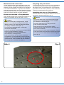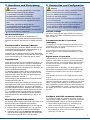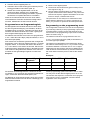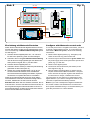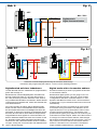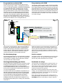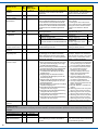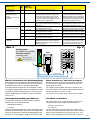
1
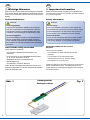
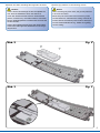
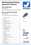
Bedienungsanleitung
Operation Manual
TT Motorischer Weichenantrieb
für Tillig-Bettungsweiche
TT Point motor for Tillig road
bed point
4557
1. Wichtige Hinweise......................................
2
2. Lieferumfang..............................................
2
3. Einleitung....................................................
3
4. Einbau / Montage....................................... 4
5. Anschluss und Einrichtung.........................
6
6.Betrieb
........................................................
13
7Wartung
......................................................
13
8.Fehlersuche & Abhilfe
................................
13
9. Technische Daten......................................
16
DC
=
1. Important information .................................2
2. Content.......................................................2
3. Introduction................................................3
4. Mounting and Connections.......................... 4
5. Connection and Configuration.....................6
6.
Operation ...................................................13
7.
Maintenance ...............................................13
8.
Troubleshooting ..........................................13
9. Technical data...........................................16
AC
~
DCC MM
DE
EN
1. Wichtige Hinweise
1. Important information
Bitte lesen Sie vor der ersten Anwendung des Produktes
bzw. dessen Einbau diese Bedienungsanleitung aufmerksam durch und bewahren Sie sie auf. Sie ist Teil des Produktes.
Please read this manual completely and attentively before using the product for the first time. Keep this manual.
It is part of the product.
Sicherheitshinweise
Safety information
Vorsicht:
Caution:
Verletzungsgefahr!
Risk of injury!
Aufgrund der detaillierten Abbildung des Originals
bzw. der vorgesehenen Verwendung kann das Produkt Spitzen, Kanten und abbruchgefährdete Teile
aufweisen. Für die Montage sind Werkzeuge nötig.
Due to the detailed reproduction of the original and
the intended use, this product can have peaks, edges
and breakable parts. For that reason this product is
not for children. For installation tools are required.
Stromschlaggefahr!
Electrical hazard!
Die Anschlussdrähte niemals in eine Steckdose einführen! Verwendetes Versorgungsgerät (Transformator, Netzteil) regelmäßig auf Schäden überprüfen.
Bei Schäden am Versorgungsgerät dieses keinesfalls
benutzen!
Never put the connecting wires into a power socket!
Regularly examine the transformer for damage. In
case of any damage, do not use the transformer!
Das Produkt richtig verwenden
Using the product for its correct
purpose
Dieser Antrieb ist bestimmt:
This product is intended:
- Zum Einbau in Modelleisenbahnanlagen und
Dioramen.
- For installation in model railroad layouts and
dioramas.
- Zum Anschluss an einem Modellbahntransformator
(z. B. Art.-Nr. 5200) bzw. an einer
Modellbahnsteuerung mit zugelassener
Betriebsspannung.
- For connection to an authorized model
railroad transformer (e. g. item-No. 5200).
- Zum Betrieb in trockenen Räumen.
Using the product for any other purpose is not approved
and is considered incorrect. The manufacturer is not
responsible for any damage resulting from the improper
use of this product.
Jeder darüber hinausgehende Gebrauch gilt als nicht
bestimmungsgemäß. Für daraus resultierende Schäden
haftet der Hersteller nicht.
Abb. 1
- For operation in dry rooms only.
Packungsinhalt
Package content
2
Fig. 1
2. Lieferumfang
Vorsicht:
2. Content
Caution:
Der Antrieb besteht aus einer empfindlichen
Elektronik- und Mechanikbaugruppe.
The point motor contains very sensitive mechanical
and electronical components.
Öffnen Sie das weitere Gehäuse unter keinen Umständen. Zerstörung des Antriebs oder Ver- letzungen
können die Folge sein.
Never open the back cover of the point motor. That
may result in destruction of the motor or injury.
Packungsinhalt überprüfen
Checking the package contents
Kontrollieren Sie nach dem Auspacken den Lieferumfang
auf Vollständigkeit:
Check the contents of the package for completeness
after unpacking:
- Weichenantrieb mit Anschlusskabel und im Kabel
befindlichem Decoder mit Vorwiderstand,
- 2 Schrauben,
- diese Anleitung.
- turnout drive unit with cable and in the cable located
decder including resistor,
- 2 screws,
- this manual.
3. Einleitung
3. Introduction
Funktionsumfang
Functions
Der Viessmann Weichenantrieb ist ein kraftvoller spezieller Antrieb mit zugehörigem Digitaldecoder zum Einbau
in TT-Bettungsweichen.
The Viessmann point motor is a powerful special drive
unit with associated digital decoder. It can be mounted in
TT-turnouts.
Der Viessmann Weichenantrieb zeichnet sich durch vorbildgerecht langsame Bewegung der Weichenzungen aus.
Geschwindigkeit und Bewegungsablauf sind elektronisch
gesteuert und gewährleisten einen feinfühligen Antrieb.
The Viessmann point motor has an extraordinary and
thus very realistic slow movement of the point rails.
Speed and motion are controlled by the built-in electronic
which warrants a very sensitive adjustment.
Hinweis:
Der Antrieb sollte nicht manuell verstellt werden, um
eventuelle Beschädigungen zu vermeiden.
Bitte das manuelle Schalten nicht erzwingen!
Notice:
The drive should not be operated manually to avoid
any damage. Please do not force the
manual shifting!
Der zugehörige Decoder versteht die Formate MärklinMotorola und DCC und kann die angeforderte Sollstellung oder die Ist-Stellung per RailCom an geeignete Digitalzentralen (z. B. Viessmann Commander Art.-Nr. 5300)
zurückmelden. Zusätzliche Schaltausgänge für konventionelle Stellungsrückmeldung vervollständigen den Funktionsumfang. Deren Funktion ist konfigurierbar.
The associated decoder is suitable for DC / AC, MM and
DCC and is able to send the requested position or the
actual position by RailCom to corresponding digital command stations (e. g. Viessmann Commander item-No.
5300). Additional switching outputs for a conventional
feedback complete the functions of the point motor. Their
function is configurable.
Geeignete Gleissysteme
Compatible Track Systems
Dieser spezielle Viessmann Antrieb kann nur in Verbindung mit TT-Tillig Bettungsweichen benutzt werden.
This special Viessmann turnout drive is only suitable for
Tillig TT turnouts with ballast.
Der Antrieb kann in folgende TT-Tillig Bettungsweichen
eingebaut werden:
The drive can be installed in the following Tillig turnouts:
-
-
-
-
-
-
- 83817 lefthand turnout, manual (EW-li)
83816 Weiche, rechts mit Handbetrieb (EW-re)
83817 Weiche, links mit Handbetrieb (EW-li)
83818 Weiche, rechts mit Elektronikantrieb (EW-re)
83819 Weiche, links mit Elektronikantrieb (EW-li)
83861 B-Innenbogenweiche, rechts (BIBW-re)
83862 B-Innenbogenweiche, links (BIBW-li)
- 83816 righthand turnout, manual (EW-re)
- 83818 righthand turnout, with electric drive (EW-re)
- 83819 lefthand turnout, with electric drive (EW-li)
- 83861 inner curved turnout type B, righthand (BIBW-re)
- 83862 inner curved turnout type B, lefthand (BIBW-li)
3
Ansteuerung im Digitalbetrieb
Operation in digital mode
Der spezielle TT-Tillig Weichenantrieb 4557 enthält einen
Multiprotokoll-Decoder, der entweder Signale im DCCFormat oder im Motorola-Format auswertet. Welches
Datenformat der Decoder auswertet, legt man bei der
Einstellung der Digitaladresse fest.
The special TT-Tillig point motor 4557 contains a multiple
protocol decoder, that can operate with and automatically
recognises both DCC or Motorola formats.
Der Adressumfang ist von dem Format abhängig, mit
dem der Decoder angesteuert wird.
Motorola-Format: 320 (1020 with appropriate
command station) addresses.
Motorola-Format: 320 (1020 bei entsprechender Zentrale) Adressen.
DCC- Format: DCC- Format: 2047 addresses.
2047 Adressen.
Ansteuerung im Analogbetrieb
Operation in analogue mode
Den Viessmann Weichenantrieb können Sie auch in konventionell gesteuerten Modellbahnanlagen einsetzen.
Sie können ihn sowohl mit Wechselstrom als auch mit
Gleichstrom betreiben.
The Viessmann point motor can be used in conventional
model railroad layouts. You may use AC or DC power
supply for operation.
Sobald Sie den Antrieb an Betriebsspannung anschließen, erkennt der integrierte Decoder automatisch, ob er
analog oder digital angesteuert wird und stellt den
entsprechenden Betriebsmodus ein.
Verhalten bei Überlastung
Bei mechanischer Überlastung schaltet der Weichenantrieb nach einer kurzen Zeit ab.
Rückmeldung mit RailCom
RailCom ist ein Zusatzprotokoll zur bidirektionalen Kommunikation in digitalen Modellbahnanlagen, die im DCCFormat gesteuert werden. Es ermöglicht z. B. die Stellungsrückmeldung der Weiche zur Digitalzentrale.
Das Versenden von RailCom-Messages ist nur in Anlagen möglich, in denen ein DCC-Signal an den Schienen
anliegt und seitens der Zentrale bzw. der Booster eine
entsprechende Austastlücke im Datenstrom erzeugt wird.
Daher ist die Nutzung der RailCom-Funktion in einer reinen Motorola-Umgebung nicht möglich.
Sofern der Decoder im Weichenantrieb die Austastlücke
registriert, sendet er nach einem erhaltenen Schaltbefehl
als Quittung die Sollstellung und Iststellung der Weiche
zurück. Bei drehendem Motor wird die geschätzte übrige
Zeit zurückgegeben, bis der Motor zum Stehen kommt.
4. Einbau / Montage
Hinweis:
Sowohl mechanische als auch elektronische Bauteile
im Inneren des Weichenantriebs und des Decoders
sind sehr empfindlich. Arbeiten Sie also sehr
vorsichtig!
Vorsicht:
Alle Anschluss- und Montagearbeiten dürfen nur bei
abgeschalteter Betriebsspannung durchgeführt
werden.
Allgemeine Hinweise
4
The number of addresses depends on the format being
used.
Das Gehäuse ist systembedingt nicht hermetisch versiegelt. Durch die Öffnungen im Gehäuse können Kleinteile
wie Streumaterial etc. ins Innere gelangen und den
Antrieb zerstören.
The integrated controller and decoder recognizes automatically if there is AC or DC power supply or a digital
signal and adjusts itself to the correct mode of operation.
Overload protection
If the point motor recognizes a mechanical overload, it
switch off to protect itself against destruction. The whole
process of switching off may last up to a short time.
Feedback with RailCom
RailCom is a protocol for bi-directional communication in
digital model railway layouts controlled in DCC. It allows
e. g. the feedback of the address or the requested position from the point motor to the digital command station.
Sending RailCom messages is only possible in layouts
with a DCC signal on the rails and if the command station
and / or the booster(s) generate a cut-out in the digital
signal. That’s why it is not possible to use RailCom in a
Motorola system without DCC.
Whenever the decoder registers the RailCom cut-out, it
answers the switching commands with the current state
of the turnout. In case of a moving motor, the estimated
remaining movement time is reported.
4. Mounting and Connections
Notice:
Be careful with the point motor. Mechanical as well
as electronical components in the point motor and the
decoder are very sensitive.
Caution:
Make sure that the power supply is switched off when
you mount the device and connect the wires!
General notice
The case is not hermetically sealed due to its concept.
Small parts like ballast etc. may get into the casing
through the openings and destroy the point motor!
Beachten Sie daher unbedingt die folgenden Hinweise:
Hinweis:
Therefore pay attention to the following notices:
Notice:
Achten Sie bei der Montage auf der Grundplatte darauf, dass die Oberfläche eben und sauber ist.
When mounting the point motor, the ground plate has
to be even and clean.
Unter dem Weichenantrieb darf kein Streumaterial
(Steine, Schotter etc.) verwendet werden. Ansonsten
können Getriebegehäuse und Mechanik verformt und
zerstört werden.
Below the point motor there must not be any material like ballast etc. Otherwise the casing could be deformed and the mechanical parts could be destroyed.
Achten Sie unbedingt darauf, dass kein Streumaterial durch die Öffnungen des Gehäuses ins Innere gelangen kann.
Prevent small materials like e.g. ballast from getting
into the casing.
Abb. 2
Fig. 2
Abb. 3
Fig. 3
5
Weichenantrieb vorbereiten
Preparing the point motor
Um den Weichenantrieb ordnungsgemäß an einer Weiche zu montieren, sind einige vorbereitende Arbeiten erforderlich. Sorgen Sie bitte als erstes für eine aufgeräumte und saubere Arbeitsfläche. Legen Sie sich außerdem
folgendes Werkzeug bereit: eine feine Pinzette (möglichst
aus Kunststoff), einen kleinen Schraubendreher (Schlitz)
sowie einen kleinen Hammer und einen Metallstift.
To mount the point motor at a turnout, some preparations
are necessary. At first you need a clean workplace. For
the following work you need these tools: A small tweezer
(if possible, use one made of plastic), a small screwdriver
as well as a small hammer and a metal pin.
Einbau des Antriebs in Tillig Weichen:
Legen Sie den Antrieb an die vorgesehene Position in der
Weiche und schrauben Sie ihn fest (Abb. 2 und 3).
Hinweis:
Die Weichen 83861 B-Innenbogenweiche, rechts
(BIBW-re) und 83862 B-Innenbogenweiche, links
(BIBW-li) müssen zum Einbau des Weichenantriebs
geringfügig modifiziert werden (Abb. 4).
Hervorstehende Metallteile (Abb. 4) verhindern
den Einbau des Antriebs.
Legen Sie die Weiche auf eine harte und ebene Fläche.
Drücken Sie die Metallstifte, eventuell
unter Zuhilfenahme von einem Metallstift und
einem Hammer, vorsichtig zurück.
Danach positionieren Sie den Antrieb auf den Anschraubdomen. Der Antriebshebel von dem Weichenantrieb muss in die Antriebsgeometrie der Weiche eingepasst werden. Jetzt schrauben Sie den Antrieb mit
den beiliegenden Schrauben fest (Abb. 3).
Abb. 4
6
Installing this drive in Tillig turnouts:
Insert the drive into the designated location in the turnout
and fasten it with the screws (fig. 2 and 3).
Notice:
The turnout 83861 inner curved turnout type B, right
(BIBW-r) and left 83862 (BIBW-li) must be modified
for installation of the drive (fig. 4).
Projecting metal parts (fig. 4) may prevent the
proper mounting of the drive.
Place the turnout on a hard and even surface.
Carefully push the metal rods back, if necessary use a
metal rod and a hammer.
Afterwards, place the drive on the screw posts. The rod
of the drive needs to be inserted into the driving mechanism of the turnout. Fasten the drive with the supplied
srews (fig. 3).
Fig. 4
5. Anschluss und Einrichtung
Vorsicht:
5. Connection and Configuration
Caution:
Alle Anschluss- und Montagearbeiten nur bei abgeschalteter Betriebsspannung durchführen!
Make sure that the power supply is switched off when
you mount the device and connect the wires!
Ausschließlich nach VDE / EN-gefertigte
Modellbahntransformatoren verwenden!
Only use VDE/EN tested special model train transformers for the power supply!
Stromquellen unbedingt so absichern, dass es bei
einem Kurzschluss nicht zum Kabelbrand kommen
kann.
The power sources must be protected to prevent the
risk of burning wires.
Widerstand und Diode an den Enden der
Anschlussdrähte sind für die Funktion erforderlich.
Keinesfalls entfernen! Widerstände
nicht mit Isolationsmaterial umhüllen, da sonst keine
ausreichende Kühlung möglich ist!
Werkseinstellungen
Ab Werk ist der Decoder auf die Digitaladresse 1
(DCC-Protokoll) eingestellt. Weitere Konfigurationsmöglichkeiten entnehmen Sie bitte der CV-Tabelle auf Seite
12.
Konventioneller (analoger) Betrieb
Im konventionellen (analogen) Betrieb schalten Sie den
Weichenantrieb mit geeigneten Tastenstellpulten (z. B.
Viessmann Tastenstellpult Art.-Nr. 5547).
Schließen Sie den Weichenantrieb und das Tastenstellpult wie in Abb. 5 gezeigt an. Verwenden Sie einen geeigneten Transformator (z. B. Viessmann Art.-Nr. 5200).
Digitalbetrieb
Dieser Decoder lässt sich als Schaltartikel ansteuern. Er
bietet aber auch den Komfort, auf einer Lokadresse angesteuert werden zu können. Dies kommt den Modellbahnern entgegen, deren Zentrale keinen bequemen Zugriff auf Schaltartikel ermöglicht.
Im digitalen Betrieb schalten Sie den Weichenantrieb
über eine Digitalzentrale. Legen Sie als erstes eine Digitaldresse fest. Lesen Sie dazu die beiden folgenden
Kapitel und beachten Sie Abb. 7.
Nach Festlegung der Digitaladresse schließen Sie den
Weichenantrieb an (Abb. 6).
Wenn aufgrund der Eigenschaften Ihrer Weiche die Bewegungsrichtung nicht mit der Schaltrichtung auf Ihrem
Eingabegerät übereinstimmt, können Sie die Stellrichtung des Antriebs umkehren. Schließen Sie nach der Programmierung beide blauen Drähte gemeinsam an (Abb.
6.1): bei Märklin/Motorola beide Drähte an den Mittelleiter; bei DCC an eine beliebige der beiden Schienen.
Alternativ können Sie die Schaltrichtung in der CV 36
ändern.
Einrichtung mit DCC-Zentralen
Zur digitalen Steuerung des Weichenantriebs müssen Sie
diesem zunächst eine Digitaladresse zuweisen.
Zur Steuerung im DCC-System gehen Sie wie folgt vor:
1. Schalten Sie das Digitalsystem aus, z. B. Not-Aus.
Es darf keine Spannung mehr am Gleis anliegen.
2. Verbinden Sie nur die rot markierte Steuerleitung
und die Stromversorgungsleitungen des Weichenantriebs (braun und gelb, Abb. 7) mit dem Gleis.
Resistor and diode at the cables are needed for proper function of the lamp. Never cut them off! Never
cover resistor or diode with insulation material, because they have to be cooled by surrounding air!
Default settings
The factory setting for the digital address is 1 (DCC format). Please find further configuration options in the CV
table on page 12.
Conventional mode of operation
(analogue)
In case that you use the Viessmann point motor on conventional layouts, use a push button panel (e. g. Push
Button Panel item-No. 5547).
Connect the point motor and the push button panel as
shown in figure 5. Use a suitable transformer (e. g. itemNo. 5200).
Digital mode of operation
This decoder can be controlled as an accessory decoder.
However, it also offers the option to be controlled with a
locomotive address. This is particularly useful for modellers who do not have a command station with easy access to accessories.
In the digital mode of operation, you use a digital command station to control the point motor. Please read the
following two chapters to learn how to set a digital address.
Connect the point motor to your digital layout as shown
in fig. 6.
If the properties of your turnout cause its motion to be the
opposite of the switching direction specified by your input
device, you have the possibility to reverse its direction.
After programming, connect both blue wires together (fig.
6.1): in a Märklin/Motorola system, connect both wires to
the middle rail; for DCC, connect both wires to any of the
two rails.
Configure with DCC command stations
To use the point motor in a digital environment, at first you
have to assign a digital address. To control the point motor
with a DCC-system, observe the following instructions:
1. Switch off the digital system (e. g. emergency off).
There must not be any power at the rails.
2. Connect only the blue wire with the red marker and
the power supply wires of the point motor (brown and
yellow, fig. 7) to the rails.
7
3. Schalten Sie das Digitalsystem ein.
4. Verbinden Sie nun die zweite (grün markierte) Steuerleitung gleichfalls mit dem Gleis (Abb. 6).
5. Senden Sie mit der Digitalzentrale nun für die
gewünschte DCC-Adresse einen Schaltbefehl.
Der Weichenantrieb empfängt den Befehl, registriert
die Adresse und quittiert dies durch Umschalten.
Damit ist der Weichenantrieb unter der neuen Adresse betriebsbereit. Falls Sie die Adresse künftig ändern
möchten, wiederholen Sie die Prozedur einfach.
Programmieren am Programmiergleis
Die Konfiguration des Antriebs können Sie auch direkt
an dem Programmierausgang von Zentralen, die DCCkompatibel sind, vornehmen. Verbinden Sie dazu die Anschlüsse des Weichenantriebs wie in Abb. 6 gezeigt mit
dem Programmierausgang Ihrer Zentrale.
Die Adresse des Antriebs wird in zwei CVs programmiert.
In CV 1 steht das untere Byte (LSB) der Adresse, in CV 9
das obere Byte (MSB).
Das Umrechnen der Adresse geschieht wie im folgenden
beschrieben. Wenn Sie eine Adresse zwischen 1 und 255
eingeben wollen, so schreiben Sie diesen Wert direkt in
CV 1. Den Wert in CV 9 setzen Sie auf Null. Höhere Werte als 255 müssen aufgeteilt werden in das MSB und das
LSB. Teilen Sie die gewünschte Adresse durch 256 und
ermitteln Sie das ganzzahlige Ergebnis und den Rest.
Beispiele:
Programming on the programming track
The configuration of the drive can also be accomplished
by connecting it directly to the programming output of the
command station. Simply connect the terminals of the
turnout drive to the programming output of the command
station as shown in fig. 6.
The address of the drive is programmed in two CVs.
In CV 1 you set the lower Byte (LSB) of the address, in
CV 9 the upper Byte (MSB).
The address is established as described below. Write
the address value directly into CV 1 if you wish to assign
an address between 1 and 255. Set CV 9 to 0. Higher
addresses than 255 must be split into the MSB and the
LSB: Divide the desired address by 256 and determine
the result without decimal points as well as the remainder.
Examples:
Adresse
ganzzahliges
Ergebnis
Rest
CV 9 = MSB
CV 1 = LSB
256
1
0
1
0
911
3
911-256x3=143
3
143
1025
4
1025-256x4=1
4
1
Die weiteren Einstellmöglichkeiten entnehmen Sie der
CV-Tabelle. In CV 40 können Sie auch das Protokoll festlegen, auf das der Weichenantrieb später „hört“.
Auf Befehle am Programmierausgang einer DCC-kompatiblen Zentrale hört der Decoder immer unabhängig vom
eingestellten Protokoll.
8
3. Switch on the digital system.
4. Connect the second blue wire (green marker) to the
track signal too (fig. 6).
5. Use the digital command station to send a turnoutrequest for the desired DCC-address. The point motor
receives the request, registers the address as its own
and as a receipt, it switches the turnout.
The point motor is now ready to be used with the new
digital address. Whenever you want to change the address, you just have to repeat the described procedure.
Further programming options are listed in the CV table.
You may also set the desired digital protocol in CV 40.
The decoder will respond to commands of the programming output of a DCC compatible command station
regardless of the set protocol.
Abb. 5
Fig. 5
rot / red
grün / green
4557
Universal Tasten - Stellpult
5547
braun
brown
16 V
Lichttransformator
Primär
230 V~
5200
Sekundär 10 V
0-10-16 V~
Primär
230 V 50 - 60 Hz
Sekundär 52 VA max. 3,25 A
IP 40 ta 25°C
0V
gelb / yellow
grün / green
5547
Nur für trockene Räume
5200
rot / red
Gefertigt nach
VDE 0570
EN 61558
Einrichtung mit Motorola-Zentralen
Configure with Motorola central units
Damit Sie den Weichenantrieb digital ansteuern können,
müssen Sie diesem zunächst eine Digitaladresse zuweisen. Zur Steuerung im Märklin-Motorola-System gehen
Sie wie folgt vor:
To use the point motor in a digital environment, you have
to assign a digital address at first. To control the point
motor with a Motorola-system, observe the following
instructions:
1. Schalten Sie das Digitalsystem aus, z. B. Not-Aus.
Es darf keine Spannung mehr am Gleis anliegen.
2. Verbinden Sie nur die grün markierte Steuerleitung
und die Stromversorgungsleitungen des Weichenantriebs (braun und gelb, Abb. 7) mit dem Gleis.
3. Schalten Sie das Digitalsystem ein.
4. Verbinden Sie die zweite (rot markierte) Steuerleitung
gleichfalls mit dem Gleis (Abb. 6).
5. Senden Sie mit der Digitalzentrale nun für die gewünschte Motorola-Adresse einen Schaltbefehl.
Der Weichenantrieb empfängt den Befehl, registriert
die Adresse und quittiert dies durch Umschalten.
Damit ist der Weichenantrieb unter der neuen Adresse betriebsbereit. Falls Sie die Adresse künftig ändern
möchten, wiederholen Sie die Prozedur einfach.
1. Switch off the digital system (e. g. emergency off).
There must not be any power at the rails.
2. Connect only the blue wire with the green marker and
the power supply wires of the point motor (brown and
yellow, fig. 7) to the rails.
3. Switch on the digital system.
4. Connect the second blue wire (red marker) to the
track signal too (fig. 6).
5. Use the digital command station to send a turnoutrequest for the desired Motorola-address. The point
motor receives the request, registers the address as
its own and as a receipt, it switches the turnout.
The point motor is now ready to be used with the new
digital address. If you want to change the address, you
just have to repeat the described procedure.
Beachten Sie: Wenn Sie eine Zentrale einsetzen, die sowohl das DCC- als auch das Motorola-Format sendet, ist
die Programmierung des Weichenantriebs im DCC-Format empfehlenswert. Im Motorola-Format ist der Adressbereich auf 320 Adressen beschränkt.
Notice: If you use a multiprotocol digital command station, which is able to use the Motorola- as well as the
DCC-system simultaneuously, it is recommended to program the point motor on a DCC-address.
9
Abb. 6
Fig. 6
4557
braun
brown
Mot. / DCC
Digitalzentrale
Digital Command Station
braun
brown
rot / red
grün / green
gelb / yellow
Abb. 6.1
Fig. 6.1
4557
4557
MM
DCC
rot / red
braun
brown
rot / red
gelb
yellow
braun
brown
Digitalzentrale
Digital
Command
Station
braun
brown
rot / red
grün / green
braun
brown
rot / red
grün / green
gelb
yellow
Digitalzentrale
Digital
Command
Station
Anschluss nach Adressprogrammierung für invertierte Stellrichtung!
Connection after programming the address - use for reverse switching direction!
10
Digitalbetrieb auf einer Lokadresse
Digital mode with a locomotive address
Um den Decoder auf eine Lokadresse zu programmieren,
gehen Sie wie folgt vor:
Proceed as follows if you wish to programm the decoder
to a locomotive address.
Bestimmen Sie, welches Digitalsystem verwendet werden soll. Gehen Sie dazu vor, wie unter den Punkten 1
bis 4 bei „Einrichtung mit DCC-Zentralen“ oder „Einrichtung mit Motorola-Zentralen“ beschrieben. Stellen Sie alle
Lokomotiven auf Fahrstufe Null, sofern Ihre Zentrale dies
nicht automatisch tut.
Decide which digital system you are going to use. Proceed as described in points 1 through 4 in the chapter
“Configurations with DCC command stations” or “Configuration with Motorola central units”. Set all locomtives
to speed step 0 if your command station does not do that
automatically.
An Punkt 5 senden Sie jedoch keinen Weichenschaltbefehl, sondern einen Lok-Fahrbefehl auf der Adresse,
die der Antrieb bekommen soll. Betätigen Sie dazu den
Fahrregler, so dass eine Fahrstufe an die Adresse gesendet wird, die nicht Null ist. Diese Adresse entspricht der
Gruppenadresse eines typischen 4-fach-Decoders. Auf
dieser Lokadresse wählen Sie dann eine Funktion F1 bis
F4, die dadurch dem Weichenantrieb zugeordnet wird.
Somit können Sie 4 Weichenantriebe auf eine Lokadresse legen, analog zum 4-fach-Decoder. Der Adressbereich
ist auf 1 bis 99 begrenzt.
Instead of the accessory command as per point 5 send
a locomotive driving command to the address to be assigned to this drive. Turn up the throttle in order to send
a speed command greater than 0. This address corresponds with the typical group address of an accessory decoder with four double-outputs. Select one of the functions
F1 through F4 of this locomotive address, which assigns
the functions of this address to the turnout drive. Thus you
may control four turnouts with one locomotive address
similar to a decoder for four accessories. The address
range is limited to addresses from 1 through 99.
Programmieren mittels POM
Programming with POM
Der Decoder lässt die Programmierung aller CVs per
POM („Programming on Main“, „Hauptgleisprogrammierung“) zu. Nicht alle Zentralen unterstützen POM-Befehle
an Schaltartikel-Decodern, deswegen kann man den
Decoder auch auf Lokdecoder-POM Modus umstellen.
Dies geschieht dadurch, dass auf der Adresse 9999 der
Wert 80 in die CV 8 geschrieben wird. Der Weichendecoder hört dann auf normale POM-Befehle für Lokomotiven unter seiner aktuellen Adresse. Bitte beachten Sie,
dass hier aus Sicherheitsgründen immer zunächst CV 1
und dann CV 9 geschrieben werden müssen, auch dann,
wenn sich der Inhalt von CV 9 nicht geändert hat.
The decoder supports programming of all CVs per POM
(“Programming on the Main”). Since not all command stations support POM for accessory decoders you may also
set the decoder to respond to the locomotive POM mode.
Enter the value 80 in CV 8 of the address 9999. Then the
turnout decoder responds to normal POM commands for
locomotives under the respective address. For safety you
should first edit CV 1 and then CV 9, even if the value of
CV 9 didn’t change.
Abb. 7
Fig. 7
4557
Adresse einstellen / Set address
rotes Kabel verbinden / connect red cable
DCC
Motorola
grünes Kabel verbinden / connect green cable
gelb / yellow
grün
green
rot
red
braun / brown
Mot. / DCC
Digitalzentrale
Digital Command Station
Hier ist also Vorsicht geboten, damit nicht gleichfalls Lokomotiven, die diese Adresse haben, umprogrammiert
werden. Gleichnamige Lokomotiven müssen entfernt
werden oder der entsprechende Stromkreis muss abgeschaltet werden. Unter RailCom werden die entsprechenden Nachrichten an die Zentrale gesendet.
Please be careful to avoid inadvertent programming of
other locomotives with the same address. Remove locomotives with the same address from the track or disconnect power to such track sections. If RailCom is active
then the corresponding feedback will be sent to the command station.
Die Schaltausgänge
Switch outputs
Die Schaltausgänge können auf verschiedene Funktionalitäten konfiguriert werden (CV 38). Sie sind vorgesehen
zum Schalten von Relais, können aber kleine Verbraucher wie LEDs auch direkt schalten.
The switch outputs can be configured to suit various functionalities (CV 38). The outputs are intended for relays,
but can also power small loads such as LEDs.
Stellungsrückmeldung per Relais
Feedback via relays
Der Weichenantrieb verfügt über einen Transistor-Schaltausgang zur Rückmeldung der Weichenstellung. Zu seiner Standardkonfiguration kann er damit beispielsweise bistabile Relais schalten. Der Kontakt wird jeweils
am Ende des vorgesehenen Stellweges der Weiche für
ca. 250 ms eingeschaltet.
The point motor is equipped with a transistor-driven output, which is able to indicate the position of the turnout.
This output is used to operate latching relays. The contact is turned on for approx. 250 ms, when the turnout
reaches its respective end position.
Sie können über diese als Lötflächen ausgeführten Kontakte die Stellung der Weichenzunge an ein geeignetes
Steuerungssystem zurückmelden oder Schaltvorgänge
wie eine separate Herzstückpolarisierung auslösen.
Aufgrund der geringen Belastbarkeit und der kurzen
Schaltzeit nutzen Sie auf jeden Fall ein Relais wie z. B.
das Elektronische Relais (Art.-Nr. 5552). Zum Anschluss
siehe Abb. 8.
With these contacts (soldering pads on the back of the
casing), you may feedback the position of the turnout to a
suitable control system. The second use is to switch the
polarisation of the core of a turnout.
Due to the low maximum load of the contacts and the
short pulse length, it is important to use a relais (e. g. the
Viessmann electronic relay 5552) as shown in figure 8.
11
Name der CV
Name of CV
CVNr.
No.
Eingabewerte Erläuterungen / Hinweise
(Default)
value range
Remarks
Contains the lower 8 bits of the
decoder address. Thus the address is
saved in conjunction with CV 9.
Read only!
Adresse
Address
1
0 … 255 (1)
Versionsnummer
Version number
Hersteller
Manufacturer
7
(1)
8
(109)
Adresse MSB
Address MSB
Konfiguration
configuration
9
0 … 7 (0)
29
(136)
Weichenstellung
Position of the turnout
Richtung
Direction
Stellzeit
Regulating time
33
Schaltausgang
Function output
36
(0)
37
0...50(25)
38
(1)
Enthält die unteren 8 bit der Decoderadresse.
Zusammen mit CV 9 wird so die Adresse
gespeichert.
Nur lesbar
Nur lesbar /
Reset auf Werkseinstellungen. Durch Eintragen des Wertes 8 wird der Weichenantrieb
auf den Auslieferungszustand zurückgesetzt.
Schreiben von Wert 9 setzt alle Werte außer
die Adresse auf den Auslieferungszustand
zurück.
Obere 3 bits. Zusammen mit CV 1 wird so die
Adresse gespeichert.
Bit
kein RailCom
3
RailCom eingeschaltet
7
Decoder schaltet auf Lokfunktionen
Read only! /
Factory Reset.
By entering the value 8 the turnout
drive is reset to factory default values.
Writing the value 9 resets all values
except for the address to default
values.
Upper 3 bits. The address is saved in
conjunction with CV 1.
Wert
0
No RailCom
RailCom turned on
8
Decoder responds to locomo- 0
tive functions
128
Decoder schaltet auf Schaltartikelbefehle Decoder responds to accessory commands
Wird von einigen Zentralen zur Auslesung von Used by some command stations for
Weichenstellungen benutzt.
reading of switch positions.
0 = normal, 1 = invertiert
0 = normal, 1 = inverted
Laufzeit des Antriebs in 0,1 Sekunden Schritten. Abhängig von der Weichenmechanik
werden sehr kleine oder sehr große Werte
zu den schnellsten bzw. zu den langsamsten
Bewegungen gerundet.
0: inaktiv
1: Wenn eine Bewegung beendet wird, wird
der entsprechende Ausgang kurz eingeschaltet (Grundeinstellung).
2: Wenn eine Bewegung startet, wird der entsprechende Ausgang kurz eingeschaltet.
3: Ausgang zeigt den aktuellen Zustand
an. Während der Bewegung sind beide
Ausgänge aus.
4: Ausgang zeigt den aktuellen Zustand
an. Während der Bewegung ist der alte
Zustand angezeigt.
5: Ausgang zeigt den aktuellen Zustand an.
Während der Bewegungen ist der neue
Zustand angezeigt.
6: Decoderadresse+1 schaltet die Ausgänge
als Dauerausgänge um.
8: Umschaltung der Herzstückpolarisierung
erfolgt bei 40% des Weges.
9: Umschaltung der Herzstückpolarisierung
erfolgt bei 50% des Weges.
10: Umschaltung der Herzstückpolarisierung
erfolgt bei 60% des Weges.
11: Umschaltung der Herzstückpolarisierung
erfolgt bei 70% des Weges.
Running time of the drive in 0.1 second steps. Subject to the mechanics
of the turnout very small or very large
values will be rounded either to the
fastest or slowest movement.
0: inactive
1: Once a movement has finished the
corresponding output is switched
on for a moment (default setting).
2: If a movement commences then
the corresponding output is
switched on for a moment.
3: The output displays the current
status. During movement both
outputs are switched off.
4: The output displays the current
status. During movement the previous status is still displayed.
5: The output displays the current
status. During movement the new
status is displayed.
6: Decoder address+1 switches the
outputs.
8: Switching point for the core polarisation at 40% of the movement.
9: Switching point for the core polarisation at 50% of the movement.
10: Switching point for the core polarisation at 60% of the movement.
11: Switching point for the core polarisation at 70% of the movement.
0 = DCC; 1 = Motorola
Protokoll
40 (0)
0 = DCC; 1 = Motorola
Protocol
Folgende CVs sind spezielle Einstellungen für die Motorsteuerung. Die Werte sind werksseitig optimiert und sollen in der Regel nicht
verändert werden!
The following CVs are intended for configuring the motor controller. The values have been optimised ex works and should normally not be
changed!
Lastregelparameter KP
51 0 … 255 (75)
Reglerparameter
Parameters for the motor load control.
Lastregelparameter KI
52 0 … 255 (40)
Lastregelparameter KD
53 0 … 255 (10)
EMK Messungen
54 (8)
Anzahl von EMK Messungen, je Zyklus. Die
Number of EMF measurements per
EMF measurements
ersten 2 Messungen werden automatisch
cycle. The first two measurements will
ignoriert.
be automatically ignored.
12
Name der CV
Name of CV
Reglerperiode
control period
Empfindlichkeit der
Blockierungsdetektierung
Sensetivity of blocking
detection
Maximale Motorleistung
maximal motor power
Kalibration
Calibration
Eingabewerte Erläuterungen / Hinweise
(Default)
value range
Remarks
55
(8)
Gesamte Reglerperiode in 0,5 ms.
Entire control period in 0.5 msec.
56
(100)
57
(150)
58
0...255(255)
59
0...255 (180)
60
0...255 (120)
61
0...255(80)
62
(0)
Zeit in 10 ms wie lange der Motor nach einer
erkannten Blockierung weiter angetrieben
wird. Es ist nur dann aktiv, wenn weniger
als 3/4 des Gesamtwegs gefahren sind. In
dem letzten Viertel wird der Motor bei einer
Blockierung sofort abgeschaltet.
Anzahl der Reglerzyklen nach dem Motorstart, ab wann die Blockierungsdetektierung
aktiviert wird.
Wird auf diesen Wert reduziert, sobald 1/8
des Weges absolviert wurden.
Wird auf diesen Wert reduziert, sobald 6/8
des Weges absolviert wurden.
Wird auf diesen Wert reduziert, sobald 7/8
des Weges absolviert wurden.
Wird auf diesen Wert reduziert, sobald 8/8
des Weges absolviert wurden.
Mit Schreiben des Wertes 206 wird eine
Kalibrierung der Motorendstufe ausgeführt.
Damit lernt der Decoder wie die Endpunkte
der Bewegung sind.
Time in 10 ms that the motor keeps running after having detected a mechanical
resistance (blocking). It is only active if less
than ¾ of the entire movement have been
completed. In the last quarter the motor will
be turned off immediately if blocked.
Number of control cycles after the motor has started from which point on the
motor blocking detection is active.
Will be reduced to this value as soon as
1/8 of the movement has been completed.
Will be reduced to this value as soon as
6/8 of the movement has been completed.
Will be reduced to this value as soon as
7/8 of the movement has been completed.
Will be reduced to this value as soon as
8/8 of the movement has been completed.
The motor end stage is calibrated
when writing the value 206. Thus the
decoder “gets to know” the end positions of the required movement.
CVNr.
No.
Abb. 8
Fig. 8
Schaltkontakte
(als Lötflächen ausgeführt)
Feedback outputs
(soldering pads)
4557
Max. Strom: 50 mA
Max. current: 50 mA
Elektr. Relais 5552
3 x blau / blue
Weitere Funktionen der Schaltausgänge
Other functions of the switch outputs
Außer dem schon beschriebenen Schaltimpuls können
die Ausgänge auch auf Dauerkontakt mit verschiedenen
Signalisierungen (siehe CV 38) geschaltet werden.
Besides the switch pulse already described, the outputs
can also be set to continuous mode with various commands (refer to CV 38).
Eine Besonderheit ist, dass sich die Ausgänge als Dauerausgänge digital schalten lassen. Die Adresse ist dann
automatisch die Decoderadresse plus 1 (siehe CV 38).
The outputs can be digtially switched as continous outputs. The address of the output is then automatically the
decoder address plus 1 (see CV 38).
Weitere Möglichkeiten entnehmen Sie der CV-Tabelle
unter CV 38.
You will find more options under CV 38 in the CV table.
Stellungsrückmeldung per RailCom
Feedback via RailCom
Der Weichenantrieb sendet über RailCom folgende
Informationen an die Digitalzentrale:
The point motor sends via the RailCom protocol the following information to the digital command station:
-Stellungsrückmeldung
-CV-Inhalt
Damit dies genutzt werden kann, muss die Zentrale den
Decoder als Einzeldecoder adressieren. Bei einigen Zentralen ist es aber üblich, dass Rückmeldeabfragen gruppenweise, in Vierergruppen, erfolgen. Dies führt zu Stö-
- position of the turnout
- CV contents
For this option the command station must address the
decoder as individual decoder. However, some command
stations process feedback in groups (groups of 4). This
leads to faulty feedback if there is more than one drive in
13
rungen in der Übertragung, wenn sich mehr als ein Antrieb in einer Gruppe befindet. Wollen Sie Stellungsrückmeldung per RailCom nutzen, so lesen Sie im Handbuch
Ihrer Zentrale, wie die Abfrage erfolgt.
Im Falle von Problemen mit RailCom legen Sie einfach
nur einen Antrieb in eine Adressgruppe. Welche Adresse in der Gruppe Sie belegen, ist beliebig. Die anderen
Adressen dieser Gruppe können Sie für weitere Decoder ohne RailCom nutzen (Gruppenadressen: Gruppe 1:
Adresse 1 bis 4, Gruppe 2: Adresse 5 bis 8, usw.).
6. Betrieb
6. Operation
Weichen schalten
Operate turnout
Drücken Sie die entsprechende Taste auf dem Tastenstellpult (konventioneller Betrieb) oder senden Sie einen
entsprechenden Befehl an die Adresse des Weichenantriebs (digitaler Betrieb). Der Weichenantrieb schaltet die
Weiche vorbildgerecht langsam um. Dies dauert etwa 2,5
Sekunden. Während der Stellzeit speichert der Antrieb
einen weiteren Befehl, der eine andere als die aktuelle
Stellung bedeutet und führt diesen nach einer kurzen
Kühlzeit (ca. 0,5 Sek.) aus.
Press the appropriate button on the push-button-panel
(conventional use) or send an appropriate request / order
to the address of the point motor (digital use).
7. Wartung
7. Maintenance
Hinweis:
Zerlegen Sie niemals den Weichenantrieb. Zerstörung des Antriebs oder Verletzungen können die Folge sein.
Der Viessmann Weichenantrieb ist wartungsfrei.
The point motor turns now the turnout with a realistic
speed. This operation lasts approx. 2.5 seconds. During
this operation, the point motor saves another request /
order, if this means another position and executes it after
a short breake of about 0.5 secs.
Notice:
Never dismantle the turnout drive. This may result in
damage or injury.
The Viessmann point motor is maintenance-free.
8. Fehlersuche & Abhilfe
8. Troubleshooting
Jedes Viessmann-Produkt wird unter hohen Qualitätsstandards gefertigt und vor seiner Auslieferung geprüft.
Sollte es dennoch zu einer Störung kommen, können Sie
anhand der folgenden Punkte eine erste Überprüfung
vornehmen.
Every Viessmann-product is manufactured under high
quality standards and is tested before delivery. If there is
a fault nevertheless, you can do a first check.
Weichenantrieb schaltet hörbar, aber die
Weiche schaltet nicht um.
- Prüfen Sie den Einbau des Antriebs in die Weiche.
- Prüfen Sie die freie Bewegung des Antriebs und seine
Weichenmechanik.
- Mögliche Ursache: Der Betätigungsarm des Antriebs
ist nicht entsprechend zu der Weichenmechanik angeschlossen.
- Mögliche Ursache: Streumaterial (Stein, Kies) ist an
den Betätigungsarm des Antriebs gelangt.
Antrieb wird sehr heiß und/oder beginnt
zu qualmen.
- Trennen Sie sofort die Verbindung zur Versorgungsspannung!
- Prüfen Sie, ob der Weichenantrieb gemäß Anleitung
verkabelt wurde.
- Prüfen Sie die Unversehrtheit des Elektronikgehäuses.
- Mögliche Ursache: Kurzschluss. Der Antrieb wurde
14
the same group. If you wish to utilise the RailCom feedback please consult the manual of your command station
regarding the request of feedback. Should you encounter
problems with RailCom simply assign only one drive to
one address group. It is immaterial which address of the
group you choose. You may utilise the other addresses of
this group for decoders without RailCom (group addresses: group 1: address 1 through 4, group 2: addresses 5
through 8, etc.).
Point motor works audible, but the
turnout doesn’t move.
- Check the correct installation of the drive in the turnout.
- Check for free movement of the drive and the turnout
mechanics.
- Possible cause: The actuating rod of the drive is not
properly connected to the turnout mechanics.
- Possible cause: Scenery material (little pebbles, ballast, etc.) has come into the area of the actuating rod.
Point motor is getting very hot and / or
starts to smoke.
- Disconnect the system from the mains immediately!
- Check if the wiring was made correctly as shown in
this manual.
- Check the state of the electronics enclosure for
damage.
- Possible cause: Short circuit. The point motor was not
connected correctly.
- Possible cause: The electronics enclosure is damaged or is in contact with metal parts.
nicht ordnungsgemäß angeschlossen.
- Mögliche Ursache: Die Isolation des Decoders im Zuleitungskabel wurde beschädigt und ist mit Metallteilen in Berührung gekommen.
Antrieb schaltet in falscher Richtung.
- Prüfen Sie ob das Steuerkabel gemäß Abb. 6 oder
Abb. 6.1 angeschlossen wurde.
- Prüfen Sie ob die CV 36 richtig programmiert wurde.
Antrieb schaltet nicht.
- Prüfen Sie zunächst im Analogbetrieb, ob der Antrieb
arbeitet. Falls ja, so gibt es wahrscheinlich einen Fehler bei der Adress- oder Protokollprogrammierung.
Wiederholen Sie diese. Ggf. setzen Sie den Antrieb
auf die Werkseinstellungen zurück (CV 8 auf Wert 8
programmieren).
Wenn Sie die Fehlerursache nicht finden können, senden
Sie den Weichenantrieb bitte in der Originalverpackung
zur Reparatur ein (Adresse s. u.).
Drive moves in the wrong direction.
- Check the wiring of the control cables as per fig. 6 or
fig. 6.1.
- Check if CV 36 is programmed correctly.
Drive does not operate
- First check if the drive works in annalogue mode. If it
does then the most likely cause is an error in the address or protocol programming. Repeat them and if
necessary, reset the decoder to default values (programm CV 8 to value 8).
If the product is damaged, send it in the original package
directly for repair to your local dealer or to the Viessmann
company (see below for address).
9. Technische Daten
9. Technical data
Betriebsspannung (analog):
14-24 Volt ~/=
Betriebsspannung (digital):
max 24 Volt (eff.)
Stromaufnahme (Ruhestrom):
ca. 30 mA
Stromaufnahme (im Schaltmoment):
< 100 mA
Operating voltage (analogue):
Operating voltage (digital):
Current consumption (without load):
Current consumption (switch moment):
Datenformat:
DCC und Märklin-Motorola
Rückmeldeprotokoll:RailCom
Data format:
Feedback log:
Kontaktbelastbarkeit (Rückmelderausgänge):
Max. total current (feedback outputs):
50 mA
Schutzart:
IP 00
Umgebungstemperatur (Betrieb):
+8 - +35 °C
Zulässige relative Luftfeuchtigkeit:
max. 85 %
Gewicht: ca. 10,5 g
Abmessungen:
68,4 mm x 25,2 mm x 5,3 mm
Die aktuelle Version der Anleitung finden Sie auf der
Viessmann-Homepage unter der Artikelnummer.
14-24 V ~/=
max. 24 V eff.
approx. 30 mA
< 100 mA
DCC and Motorola (MM)
RailCom®
50 mA
Protected to:
IP 00
Ambient temperature in use:
+8 – +35 °C
Comparative humidity allowed:
max. 85 %
Weight: ca. 10.5 g
Dimensions:
68.4 mm x 25.2 mm x 5.3 mm
The latest version of the manual can be looked up at the
Viessmann homepage using the item-No.
RailCom® ist ein eingetragenes Warenzeichen der / is a registered trademark of Lenz-Elektronik GmbH, Gießen.
Märklin ist ein eingetragenes Warenzeichen der / is a registered trademark of Gebr. Märklin & Cie GmbH, Göppingen.
Motorola ist ein eingetragenes Warenzeichen der / is a registered trademark of Motorola Inc., Tempe-Phoenix / Arizona (USA).
Weitere Produkt- oder Firmennamen können Marken oder Handelsnamen ihrer jeweiligen Inhaber sein.
DE Modellbauartikel, kein Spielzeug! Nicht geeignet für Kinder
unter 14 Jahren! Anleitung aufbewahren!
NL
Modelbouwartikel, geen speelgoed! Niet geschikt voor
kinderen onder 14 jaar! Gebruiksaanwijzing bewaren!
EN Model building item, not a toy! Not suitable for children
under the age of 14 years! Keep these instructions!
IT
Articolo di modellismo, non è un giocattolo! Non adatto
a bambini al di sotto dei 14 anni! Conservare instruzioni
per l’uso!
ES
Artículo para modelismo ¡No es un juguete! No
recomendado para menores de 14 años! Conserva las
instrucciones de servicio!
FR
Ceci n’est pas un jouet. Ne convient pas aux enfants de
moins de 14 ans ! C’est un produit décor! Conservez cette
notice d’instructions!
PT Não é um brinquedo!Não aconselhável para menores de
14 anos. Conservar a embalagem.
ModellspielwarenGmbH
GmbH
Modellspielwaren
Am Bahnhof 1
D - 35116 Hatzfeld-Reddighausen
www.viessmann-modell.de
87771
Stand 04/sw
12/2014
Ho/Za
15