1
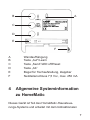
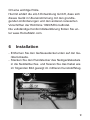
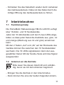
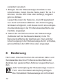
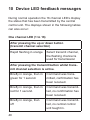
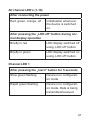
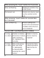
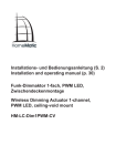
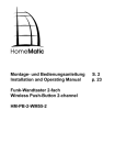
Installations- und
Bedienungsanleitung
HomeMatic-Statusanzeige
LED16
HM-OU-LED16 Seite 2 - 23
Installation and
Operating Manual
HomeMatic Status Monitor
LED16
HM-OU-LED16
Page 24 - 45
1. Ausgabe Deutsch 02/2012
Dokumentation © 2012 eQ-3 Ltd., Hong Kong
Alle Rechte vorbehalten. Ohne schriftliche Zustimmung des Herausgebers darf dieses Handbuch auch
nicht auszugsweise in irgendeiner Form reproduziert
werden oder unter Verwendung elektronischer, mechanischer oder chemischer Verfahren vervielfältigt oder
verarbeitet werden.
Es ist möglich, dass das vorliegende Handbuch noch
drucktechnische Mängel oder Druckfehler aufweist.
Die Angaben in diesem Handbuch werden jedoch
regelmäßig überprüft und Korrekturen in der nächsten
Ausgabe vorgenommen. Für Fehler technischer oder
drucktechnischer Art und ihre Folgen übernehmen wir
keine Haftung.
Alle Warenzeichen und Schutzrechte werden anerkannt.
Printed in Hong Kong
Änderungen im Sinne des technischen Fortschritts
können ohne Vorankündigung vorgenommen werden.
103579 / V 1.2
2
Inhaltsverzeichnis
1
Hinweise zu dieser Anleitung . . . . . . . . . . . . . . 4
2Gefahrenhinweise . . . . . . . . . . . . . . . . . . . . . . . 4
3Funktion . . . . . . . . . . . . . . . . . . . . . . . . . . . . . . 5
4
Allgemeine Systeminformation zu HomeMatic . . 7
5
Allgemeine Hinweise zum Funkbetrieb . . . . . . . 8
6Installation . . . . . . . . . . . . . . . . . . . . . . . . . . . . . 9
7Inbetriebnahme . . . . . . . . . . . . . . . . . . . . . . . . 11
7.1Funktionsprinzip . . . . . . . . . . . . . . . . . . . . . . . 11
7.2 Anlernen an die Zentrale . . . . . . . . . . . . . . . . . 11
8Bedienung . . . . . . . . . . . . . . . . . . . . . . . . . . . . 12
8.1 Aktorkanäle (Statusanzeige) . . . . . . . . . . . . . . 13
8.2 Sendekanäle (Eingangskanäle) . . . . . . . . . . . 13
8.3 Anzeige bis zur nächsten Aktualisierung
ausschalten . . . . . . . . . . . . . . . . . . . . . . . . . . . 15
8.4 Anzeigehelligkeit einstellen . . . . . . . . . . . . . . . 17
9
Zurücksetzen in den Auslieferungszustand . . . 17
10 Signalisierungen der LEDs . . . . . . . . . . . . . . . 19
11Wartung . . . . . . . . . . . . . . . . . . . . . . . . . . . . . . 22
12 Technische Daten . . . . . . . . . . . . . . . . . . . . . . 22
3
1 Hinweise zu dieser Anleitung
Lesen Sie diese Anleitung sorgfältig, bevor Sie Ihre
HomeMatic Komponenten in Betrieb nehmen.
Bewahren Sie die Anleitung zum späteren Nachschlagen auf!
Wenn Sie das Gerät anderen Personen zur Nutzung
überlassen, übergeben Sie auch diese Bedienungsanleitung.
Benutzte Symbole:
Achtung! Hier wird auf eine Gefahr hingewiesen.
Hinweis. Dieser Abschnitt enthält zusätzliche
wichtige Informationen!
2Gefahrenhinweise
Der Betrieb des Gerätes ist ausschließlich am mitgelieferten Netzteil (7,5 VDC) zulässig.
Falls das mitgelieferte Netzteil ersetzt werden muss,
ist folgender Hinweis ist zu beachten:
Zur Gewährleistung der elektrischen Sicherheit muss
es sich bei der speisenden Quelle um eine Sicher4
heits-Schutzkleinspannung handeln. Außerdem muss
es sich um eine Quelle begrenzter Leistung gemäß
EN60950-1 handeln, die nicht mehr als 15 W liefern
kann. Üblicherweise werden beide Forderungen von
handelsüblichen Steckernetzteilen mit entsprechender
Leistung erfüllt.
Betreiben Sie das Gerät nur in Innenräumen
und vermeiden Sie den Einfluss von Feuchtigkeit, Staub sowie Sonnen- oder andere Wärmebestrahlung.
3Funktion
Mit der HomeMatic Statusanzeige können Sie sich die
Zustände von Geräten in Ihrem HomeMatic System
anzeigen lassen. So kann man auf einen Blick erkennen, ob ein Gerät ein- oder ausgeschaltet ist. Auch der
Zustand von Systemvariablen ist über entsprechende,
auf der HomeMatic-Zentrale laufende Programme, auf
der Statusanzeige darstellbar. So kann man mit der
HomeMatic Statusanzeige z.B. die Scharf- bzw. Unscharfschaltung der internen und externen Alarmzone
oder das auslösende Gerät im Alarmfall wie z.B. Bewegungsmelder oder Fensterkontakte darstellen.
Die HomeMatic-Statusanzeige hat 16 Ausgangska5
näle (Aktorkanäle), die von der HomeMatic-Zentrale
angesteuert werden können. Dabei sind auf jedem
Kanal vier Zustände durch den Anzeigestatus und verschiedene Farben darstellbar: aus rot / grün / orange
(Mischung rot + grün).
Zusätzlich sind 16 Eingangs- (Sende-) Kanäle vorhanden, die Programme in der Zentrale steuern bzw.
auslösen können. Diese Kanalsteuerung erfolgt über
drei Tasten auf der Geräterückseite.
Da sowohl die Eingangskanäle als auch die Ausgangskanäle über die Zentrale frei einstellbar sind, kann
man die Statusanzeige sehr flexibel an die eigenen
Bedürfnisse anpassen.
Bitte beachten!
Die HomeMatic-Statusanzeige unterstützt keine direkten Verknüpfungen zu Sendern oder
Aktoren. Sie muss immer an einer Zentrale mit
Zentralenverknüpfungen betrieben werden.
Die Ausgangskanäle können nur von Zentralen-Programmen angesteuert und die Eingangskanäle nur durch Programme ausgewertet werden!
6
B
A
C
D
E
F
AWandaufhängung
B
Taste „Auf”/Learn
C
Taste „Send”/LED off/Reset
D
Taste „Ab”
E
Bügel für Tischaufstellung, klappbar
F
Netzteilanschluss 7,5 VDC, max. 250 mA
4 Allgemeine Systeminformation
zu HomeMatic
Dieses Gerät ist Teil des HomeMatic-Haussteuerungs-Systems und arbeitet mit dem bidirektionalen
7
BidCoS®-Funkprotokoll.
Die Funktion des Gerätes ist über ein Programmiergerät (Zentrale) und Software konfigurierbar. Welcher
weitergehende Funktionsumfang sich damit ergibt, und
welche Zusatzfunktionen sich im HomeMatic-System
im Zusammenspiel mit weiteren Komponenten ergeben, entnehmen Sie bitte dem HomeMatic-Systemhandbuch. Alle technischen Dokumente und Updates
finden Sie stets aktuell unter www.HomeMatic.com.
5 Allgemeine Hinweise zum
Funkbetrieb
Die Funk-Übertragung wird auf einem nicht exklusiven
Übertragungsweg realisiert, weshalb Störungen nicht
ausgeschlossen werden können.
Weitere Störeinflüsse können hervorgerufen werden
durch Schaltvorgänge, Elektromotoren oder defekte
Elektrogeräte.
Die Reichweite in Gebäuden kann stark von der im
Freifeld abweichen.
Außer der Sendeleistung und den Empfangseigenschaften der Empfänger spielen Umwelteinflüsse wie
Luftfeuchtigkeit neben baulichen Gegebenheiten vor
8
Ort eine wichtige Rolle.
Hiermit erklärt die eQ-3 Entwicklung GmbH, dass sich
dieses Gerät in Übereinstimmung mit den grundlegenden Anforderungen und den anderen relevanten
Vorschriften der Richtlinie 1999/5/EG befindet.
Die vollständige Konformitätserklärung finden Sie unter www.HomeMatic.com.
6Installation
- Entfernen Sie den Gehäusedeckel unten auf der Geräterückseite.
- Stecken Sie den Rundstecker des Netzgerätekabels
in die Netzteilbuchse und fixieren Sie das Kabel wie
im folgenden Bild gezeigt im mittleren Kunststoffsteg.
9
- Schließen Sie das Kabelfach wieder durch Aufsetzen
des Gehäusedeckels. Dabei ist das Kabel durch
die mittige Öffnung des Gehäusedeckels zu führen.
- Wenn Sie das Gerät aufstellen wollen, klappen Sie
die beiden Aufstellbügel gemäß Abbildung aus.
- Entfernen Sie die Schutzfolie von der Displayabdeckung.
Beschriftungsfeld
- Das Beschriftungsfeld ist individuell nach Bedarf herstellbar. Eine Druckvorlage für das Schriftfeld finden
Sie unter www.homematic.com im Bereich Service
unter Technische Unterlagen / Vorlagen sowie am
Ende dieser Anleitung.
- Um ein Schriftfeld einzulegen oder zu wechseln, entfernen Sie zunächst den Gehäusedeckel unten auf
der Geräterückseite.
- Drücken Sie nun mit einem dünnen, stumpfen Gegenstand die Frontabdeckung durch das links vorhandene Loch (siehe S. 9: Pfeil links unten im Bild)
nach vorn und nehmen Sie diese ab.
- Legen Sie das Schriftfeld in die vorhandene Aussparung zwischen den LED-Reihen ein und legen
Sie die Frontabdeckung wieder auf. Sie wird durch
Magnete automatisch gehalten.
10
- Schließen Sie das Kabelfach wieder durch Aufsetzen
des Gehäusedeckels. Dabei ist das Kabel durch die
mittige Öffnung des Gehäusedeckels zu führen.
7Inbetriebnahme
7.1Funktionsprinzip
Die HomeMatic Statusanzeige HM-OU-LED16 verfügt
über 16 Aktor- und 16 Sendekanäle.
Jeder der 16 Aktorkanäle wird durch zwei LEDs abgebildet, so dass jeder Kanal die Zustände aus, grün, rot
und orange (Mischung aus rot und grün) annehmen
kann.
Mit den 2 Tasten „Auf“ und „Ab“ auf der Rückseite des
Gerätes können Sie zwischen den 16 Sendekanälen
wechseln. Die 16 LEDs signalisieren dann den ausgewählten Kanal. Mit der Sende-Taste wird das Signal
ausgesendet.
7.2 Anlernen an die Zentrale
Bitte lesen Sie diesen Abschnitt erst vollständig, bevor sie mit dem Anlernen beginnen!
- Bringen Sie die Zentrale in den Anlernmodus.
- Dann können Sie eine der beiden folgenden Anlern11
varianten benutzen:
1. Bringen Sie die Statusanzeige ebenfalls in den
Anlernmodus, indem Sie die Taste „learn” für ca. 5 s
drücken, bis die LED links oben anfängt, langsam
grün zu blinken.
Lassen Sie dann die Taste los, die LED signalisiert
nun durch schnelleres Blinken den Anlernvorgang.
Ist dieser erfolgreich, wird dieses durch eine entsprechende Meldung in der PC-Benutzeroberfläche der
Zentrale angezeigt.
2. Geben Sie die Seriennummer der Statusanzeige
(Aufkleber auf der Gehäuserückseite) in die PCBenutzeroberfläche der Zentrale ein. Nun wird der
Anlernvorgang in der Statusanzeige durch schnelles,
grünes Blinken der LED links oben angezeigt.
8Bedienung
Nach dem Anlernen können die einzelnen Aktor- und
Sendekanäle über die PC-Benutzeroberfläche der
Zentrale den gewünschten Aktionen zugeordnet werden.
Jede Verknüpfung der Statusanzeige muss in
Form einer Zentralenverknüpfung erfolgen.
Die HomeMatic Statusanzeige ist nicht direkt
12
mit einem anderen HomeMatic Gerät verknüpfbar,
auch dann nicht, wenn man die Statusanzeige als
Fernbedienung bzw. Taster einsetzt.
8.1 Aktorkanäle (Statusanzeige)
Die Zuordnung der Aktorkanäle 1 – 16 auf die Aktoren
oder Sensoren, deren Status man anzeigen möchte,
erfolgt grundsätzlich über je eine Zentralenverknüpfung pro Kanal. Dabei wird das „Auslösen bei Änderung“ des jeweiligen Aktors oder Sensors in die „Wenn
Abfrage“ eingetragen und in die „Dann-Funktion“ die
jeweils gewünschte Anzeige der Statusanzeige.
Meldet ein zugeordneter Aktor den erfolgreichen Empfang eines Befehls zur Zustandsänderung zurück, erfolgt die entsprechende Zustandsanzeige auf der LEDStatusanzeige, je nach Zuordnung sind die Zustände
aus rot / grün / orange (Mischung rot + grün) möglich.
8.2 Sendekanäle (Eingangskanäle)
Die HomeMatic Statusanzeige kann als Taster/Fernbedienung für zugeordnete Aktoren eingesetzt werden.
Auch bei dem Einsatz als Taster muss jede Verknüpfung der Statusanzeige in Form einer Zentralenverknüpfung mit dem jeweiligen Aktor erfolgen.
Dabei wird in die „Wenn Abfrage“ das Auslösen des
13
Tasters eingetragen und in die „Dann-Funktion“ die jeweils gewünschte Funktion des betreffenden Aktors.
Möchte man den Aktor „toggeln“ kann man durch
Prüfen des Status des jeweiligen Aktors in die „wenn“
oder „sonst“ Funktion die jeweils gewünschte Reaktion
eingeben.
Beispiel: Wenn Taste X der Statusanzeige gedrückt
wird und der Status des Aktors YZ ist „Schaltzustand
„ein“ (Aktion „nur prüfen“), dann Schaltzustand sofort
auf „Schaltzustand aus“ wechseln.
Wenn der Aktor dann bei Tastendruck aus ist, verzweigt die Verknüpfung auf „sonst“. Dort muss die
Eingabe „Schaltzustand sofort auf „Schaltzustand aus“
eingegeben werden und der Aktor wird ausgeschaltet.
Über die drei Tasten auf der Geräterückseite können
über die Zentrale die zuvor zugeordneten Aktionen
ausgelöst werden. Die Kontrolle der Auswahl erfolgt
dabei über die LEDs des Anzeigefeldes.
- Durch Drücken der Auf- oder Ab-Taste wählen Sie
anhand der LED-Anzeige den gewünschten Kanal
aus. Dieser wird durch schnelles Blinken in orange
angezeigt.
- Während die LED blinkt, drücken Sie kurz die Taste
„send”. Jetzt leuchtet die LED während des Sendens
orange, dann nach erfolgreichem Empfang in der
14
Zentrale für ca. 1 s grün. War der Empfang nicht
erfolgreich, leuchtet die LED für ca. 1 s rot.
- Nach der Quittierung geht das Gerät wieder in den
Normalmodus (Statusanzeige).
Bitte beachten!
Wird während der Kanalwahl (LED blinkt
schnell orange) für 5 s keine weitere Taste
gedrückt, wird die Kanalauswahl beendet und
das Gerät geht wieder in den Normalmodus
(Statusanzeige).
8.3 Anzeige bis zur nächsten Aktualisierung
ausschalten
Die Anzeige-LEDs können zur Reduzierung der Leistungsaufnahme (Energiespar-Modus) ausgeschaltet
werden, dies kann automatisch nach einer einstellbaren Zeit, wie folgend unter 1. beschrieben oder manuell, wie folgend unter 2. beschrieben, erfolgen.
Im Auslieferungszustand ist eine Anzeigedauer von
255 Sekunden voreingestellt.
1. Die Statusanzeige kann über die Zentrale so konfiguriert werden, dass sie nach einer einstellbaren
Einschaltdauer automatisch die Anzeige deaktiviert.
Die Einschaltdauer kann im Bereich von 1 - 255
15
Sekunden eingestellt, oder auf „immer an“ gesetzt
werden.
Nach jeder Aktualisierung bleibt die Anzeige für die
eingestellte Einschaltdauer an, danach werden die
LEDs automatisch ausgeschaltet. Natürlich kann
auch in diesem Modus am Gerät die Anzeige mit der
Taste „send/LED off/[reset]” umgeschaltet werden,
sie schaltet sich dann aber ebenfalls nach Ablauf
der Einschaltdauer wieder aus.
2. Sie können die Anzeige jederzeit über die Taste
„send/LED off/[reset]” manuell ausschalten. Die
LEDs bleiben bis zur nächsten Aktualisierung über
Funk ausgeschaltet.
Dabei kann die Anzeige auch durch erneutes Drücken der Taste „send/LED off/[reset]” wieder eingeschaltet werden.
Das Umschalten wird jeweils durch kurzes Aufleuchten aller Kanal-LEDs signalisiert:
Beim Ausschalten der Anzeige leuchten alle KanalLEDs kurz rot und beim Einschalten kurz grün.
So hat man immer eine Rückmeldung auf die Betätigung der Taste, auch wenn die Anzeige im eingeschalteten Zustand nichts anzeigt, weil alle Kanäle
ausgeschaltet sind.
16
Bitte beachten!
Ist die LED-Anzeige ausgeschaltet, führt auch
ein kurzes Betätigen der Auf- und Ab-Taste zunächst nur zum Einschalten der LED-Anzeige,
erst mit dem zweiten Tastendruck beginnt die
Kanalauswahl.
8.4 Anzeigehelligkeit einstellen
Die Anzeigehelligkeit kann über die PCZentralensoftware in 16 Stufen eingestellt werden.
Im Auslieferungszustand ist die maximale Helligkeit
voreingestellt.
9 Zurücksetzen in den
Auslieferungszustand
- Halten Sie die Taste „send/LED off/[reset]” für mindestens 5 s gedrückt. Die LED von Kanal 1 (oben
links) blinkt rot.
- Zum Zurücksetzen des Geräts lassen Sie die Taste
kurz los und drücken sie erneut für mindestens 5 s.
- Die LED beginnt nun, während des Drückens schneller rot zu blinken.
- Lassen Sie nun die Taste los. Zur Bestätigung des
17
Zurücksetzens leuchtet die LED für etwa 1 s dauerhaft rot auf.
- Sofern Sie das Zurücksetzen abbrechen möchten,
können Sie dies mit einem kurzen erneuten Tastendruck auf die Taste tun oder Sie warten 15 s. In
beiden Fällen stoppt das langsame rote Blinken und
das Gerät kehrt zur Normalanzeige zurück.
Mögliche Fehlermeldungen beim Rücksetzen
Beginnt die Geräte-LED nach 5 s Drücken der Taste
„send/LED off/[reset]” nicht zu blinken, sondern leuchtet dauerhaft auf, kann das Gerät nicht zurückgesetzt
werden!
In diesem Falle ist die Verschlüsselung mit einem vom
Auslieferungsschlüssel verschiedenen System-Sicherheitsschlüssel aktiv. Um das Gerät zurückzusetzen,
müssen Sie die Konfigurationssoftware der Zentrale
zum Zurücksetzen benutzen! Der Vorgang ist in der
Anleitung zur Zentralen-Software beschrieben.
18
10 Signalisierungen der LEDs
Im normalen Betrieb zeigen die 16 Kanal-LEDs den
Status an, der von der Zentrale übermittelt wurde. Abweichend davon gibt es die in den folgenden Tabellen
aufgeführten Anzeigen:
Eine Kanal-LED (1...16)
Nach Drücken der Auf- oder Ab-Taste
(Sendekanal-Auswahl)
Schnelles oranges
Blinken
Auswahl des Sendekanals,
der blinkende Kanal wird
beim Senden verwendet
Nach Betätigung der Sendetaste, während die
Sendekanal-Auswahl aktiv ist
Kurz orange, dann
1 Sekunde grün
Befehl wurde gesendet, Bestätigung wurde empfangen
Kurz orange, dann
1 Sekunde rot
Befehl wurde gesendet, keine Bestätigung empfangen
Kurz orange, dann
aus
Befehl wurde gesendet, keine Zentrale angelernt
19
Alle Kanal LEDs (1-16)
Nach dem Anschließen der Betriebsspannung
Rot, grün, orange,
aus
Initialisierung, bei jedem
Einschalten
Nach Betätigung der Taste „LED off“ im normalen Anzeigebetrieb
Kurz rot
LED-Anzeige mit Taste
„LED off“ ausgeschaltet
Kurz grün
LED-Anzeige mit Taste
„LED off“ eingeschaltet
Kanal-LED 1
Nach 5 Sekunden Drücken der Taste „learn“
Langsames grünes
Blinken
Gerät im Konfigurationsmodus
Schnelles grünes
Blinken
Gerät im Konfigurationsmodus, Daten werden
gesendet/empfangen
20
Nach 5 Sekunden Drücken der Taste „reset“
Langsames rotes
Blinken
Wartet auf erneuten langen
Tastendruck
Dauerhaftes rotes
Leuchten
Gerät kann nur über Zentrale zurückgesetzt werden.
Nach zweitem Drücken für 5 Sekunden der Taste
„reset“
Schnelles rotes
Blinken
Geräteeinstellungen werden beim Loslassen der
Taste in den Auslieferungszustand zurückgesetzt
Kanal-LED 1 (rotes Blinken (Fehlercodes))
1 x lang
1 x kurz
Transceiver-Modul
konnte nicht initialisiert
werden (nach dem
Einschalten, wird endlos wiederholt)
Defekt im Gerät,
Gerät muss repariert werden
1 x lang
3 x kurz
Duty-Cycle-Überschreitung (bei
Sendeversuch, nach
Betätigung der Taste
„send“)
Momentan darf
nicht gesendet
werden. Fünf
Minuten warten.
21
11Wartung
Das Produkt ist wartungsfrei.
Reinigen Sie es nur mit einem trockenen Leinentuch,
und üben Sie dabei keinen zu starken Druck auf die
Frontscheibe aus.
12 Technische Daten
Aktorkanäle:16
Sendekanäle:16
Funkfrequenz: 868,3 MHz
Typ. Freifeldreichweite: 100 m
Funkprotokoll:BidCoS
Spannungsversorgung:
7,5 VDC
Stromaufnahme:
max. 250 mA
Abm. (B x H x T):
110 x 100 x 15 mm
22
Entsorgungshinweis
Gerät nicht im Hausmüll entsorgen!
Elektronische Geräte sind entsprechend der
Richtlinie über Elektro- und Elektronik-Altgeräte
über die örtlichen Sammelstellen für ElektronikAltgeräte zu entsorgen.
Das CE-Zeichen ist ein Freiverkehrszeichen,
das sich ausschließlich an die Behörden wendet und keine Zusicherung von Eigenschaften
beinhaltet.
23
1st English edition 02/2012
Documentation © 2012 eQ-3 Ltd. Hong Kong
All rights reserved. No parts of this manual may be
reproduced or processed in any form using electronic, mechanical or chemical processes in part or in
full without the prior explicit written permission of the
publisher.
It is quite possible that this manual has printing errors
or defects. The details provided in this manual are
checked regularly and corrections are done in the next
edition. We do not assume any liability for technical or
printing errors.
All registered trade marks and copyrights are acknowledged.Printed in Hong Kong
We reserve the right to make changes due to technical
advancements without prior notice.
103579 / V 1.2
24
Table of Contents
1
Information concerning these instructions . . . .
2
Hazard information . . . . . . . . . . . . . . . . . . . . .
3Function . . . . . . . . . . . . . . . . . . . . . . . . . . . . .
4
General system information on HomeMatic . .
5
General information on radio operation . . . . . .
6Installation . . . . . . . . . . . . . . . . . . . . . . . . . . . .
7
Start up . . . . . . . . . . . . . . . . . . . . . . . . . . . . . .
7.1 Method of operation . . . . . . . . . . . . . . . . . . . .
7.2 Teaching-in at the central control unit . . . . . . .
8Operation . . . . . . . . . . . . . . . . . . . . . . . . . . . .
8.1 Actuator channels (status display) . . . . . . . . .
8.2 Transmit channels (input channels) . . . . . . . .
8.3 Switch off display until next update . . . . . . . . .
8.4 Adjust display brightness . . . . . . . . . . . . . . . .
9
Resetting to factory status . . . . . . . . . . . . . . . .
10 Device LED feedback messages . . . . . . . . . .
11
Maintenance and cleaning . . . . . . . . . . . . . . .
12 Technical specifications . . . . . . . . . . . . . . . . . .
26
26
27
30
30
31
33
33
34
35
35
35
36
38
38
40
44
44
25
1 Information concerning these
instructions
Read these instructions carefully before beginning
operation with your HomeMatic components.
Keep the instructions handy for later consultation!
Please hand-over the operating manual as well when
you hand-over the device to other persons for use.
Symbols used:
Attention! This indicates a hazard.
Note. This section contains additional important
information!
2 Hazard information
The device has been designed exclusively for operation with the provided power supply (7.5 VDC).
If the provided power supply has to be replaced, attention must be paid to the following information:
In order to ensure that the equipment is electrically
safe, the feeding source must be a low safety voltage. It must also be a source of limited power in
accordance with EN60950 that cannot supply more
26
than 15 W. Normally, both requirements are fulfilled by
normal commercial plug-in power supplies with appropriate power.
The device may only be operated indoors and
must be protected from the effects of damp and
dust, as well as solar and other thermal radiation.
3Function
The device functions as a visual status display for
the HomeMatic system that can indicate the status of
devices that are controlled by HomeMatic actuators.
You can therefore see at a glance whether a device is
on or off. The status of system variables can also be
shown on the status display via appropriate programs
running on the HomeMatic central control unit. For
example, if an alarm function is being programmed,
the activation and deactivation of the internal and
external alarm zones can be displayed. In the event
of an alarm, you could also have the cause displayed
by having the central control unit show the status of
movement sensors and window contacts on the status
display.
27
For this function the device has 16 output channels
(actuator channels) that can be actuated by the HomeMatic central control unit. Four statuses can be shown
on each channel using the display status and different
colours: off - red - green - orange (mixture of red +
green).
16 input (transmit) channels are also present, which
can control or trigger the programs in the central control unit. This channel control takes place using three
buttons on the rear of the device.
Since both the input channels and the output channels
are freely configurable by the central control unit, the
status indicator can be adapted to your own needs in
an extremely flexible way.
Please note!
The status indicator does not support direct
connections between transmitters and actuators. The output channels can only be actuated
by programs, and the input channels can only
be evaluated by programs!
28
B
A
C
D
E
F
A
B
C
D
E
F
Wall mounting
„Up“/Learn button
„Send“/LED off/Reset button
„Down“ button
Bracket for table-top installation, hinged
Power supply connection 7.5 VDC, max. 250 mA
29
4 General system information on
HomeMatic
This device is a part of the HomeMatic home control
system and works with the bidirectional BidCoS® wireless protocol.
All devices are delivered in a standard configuration.
The functionality of the device can also be configured
with a programming device and software. Further
resulting functionality and the additional functions provided in the HomeMatic system combined with other
components are described in the separate Configuration Instructions and in the HomeMatic System Manual.
All current technical documents and updates are provided under www.HomeMatic.com.
5 General information on radio
operation
Radio transmission is performed on a non-exclusive
transmission path, which means that there is a possibility of interference occurring.
Interference can also be caused by switching operations, electrical motors or defective electrical devices.
30
The range of transmission within buildings can differ
greatly from that available in the open air.
Besides the transmitting power and the reception characteristics of the receiver, environmental factors such
as humidity in the vicinity have an important role to
play, as do on-site structural/screening conditions.
eQ-3 Entwicklung GmbH hereby declares that this
device complies with the essential requirements and
other relevant regulations of directive 1999/5/EC.
The full declaration of conformity can be viewed at
www.HomeMatic.com.
6Installation
- Remove the housing cover at the bottom on the rear
of the device.
- Insert the round plug of the power supply cable into
the power supply socket and fix the cable in the
plastic strip in the centre, as shown in the following
picture:
- Close the cable compartment by replacing the
housing cover. The cable must be led through the
central opening in the housing cover.
- If you wish the raise the device up, fold out the two
31
supports as shown in the picture.
- Remove the protective film from the display cover.
Label field
- The label field can be created individually to suit your
requirements. A printing template for the label field
can be found at www.homematic.com in the service
area under Technical documentation / Templates and
can be found at the end of these instructions.
- To insert or replace a label field, first remove the
housing cover at the bottom on the rear of the device.
- Now push the front cover forwards through the hole
on the left with a thin, blunt object (see arrow in pic-
32
ture on left) and remove it.
- Place the label field in the existing recess between
the rows of LED‘s and replace the front cover. It is
held in place automatically by magnets.
- Close the cable compartment by replacing the
housing cover. The cable must be led through the
central opening in the housing cover.
7 Start up
7.1 Method of operation
The HomeMatic HM-OU-LED16 status display has 16
actuator channels and 16 transmit channels.
Each of the 16 actuator channels is represented by
two LED‘s, meaning that each channel can have a
status of off, green, red, or orange (mixture of green
and red).
The 16 transmit channels are also symbolised by the
16 LED‘s, since the device only has 3 buttons. One of
the 16 channels can be selected by pressing the up
and down buttons, and the signal can be transmitted
by pressing the Send button.
33
7.2 Teaching-in at the central control unit
Please read this entire section before starting
the teach-in procedure!
- Switch the central control unit to teach-in mode.
- One of the two following teach-in variants can then
be used:
1. Also switch the status display to teach-in mode by
pressing the “learn” button for approx. 5 seconds
until the LED at the top left starts to flash slowly in
green.
Release the button, and the LED now signals the
teach-in procedure by flashing more quickly.
Once this has been carried out, an appropriate message appears on the PC user interface of the central
control unit.
2. Enter the serial number of the status display (sticker
at the back of the device) on the PC user interface of
the central control unit. Now the teach-in procedure
is indicated on the status display by rapid flashing of
the LED at the top left in green.
34
8Operation
After teaching in, the individual actuator and transmit
channels can be assigned to the required actions via
the PC user interface of the central control unit.
8.1 Actuator channels (status display)
If an assigned actuator signals successful receipt of
a status change command, the relevant status is displayed on the LED status display. Depending on the
assignment, statuses of off - red - green and orange
(mixture of red and green) are possible.
8.2 Transmit channels (input channels)
The previously assigned actions can be triggered via
the three buttons on the rear of the device. The selection is monitored via the LED‘s of the display field.
- Select the required channel using the LED display by
pressing the up or down button. This is indicated by
rapid flashing in orange.
- Whilst the LED is flashing, briefly press the „Send“
button. Now the LED illuminates in orange during
transmission, then in green for approx. 1 second
after successful receipt at the central control unit.
If receipt was unsuccessful, the LED illuminates for
approx. 1 sec. in red.
35
- After acknowledgement, the device reverts to normal
mode (status display).
Please note!
If no other button is pressed for 5 sec. during
channel selection (LED flashes rapidly in orange), channel selection is terminated and the
device reverts to normal mode (status display).
8.3 Switch off display until next update
The display LED‘s can be switched off automatically
after a certain time (adjustable) to reduce power consumption (eco mode) as described in the following under 1. or manually, as described in the following under
2.
A display time of 255 seconds is preset in the as-delivered condition.
1. The status display can be configured by the central
control unit in such a way that it automatically deactivates the display after an adjustable „on“ time. The
„on“ time can be set to a period of 1 to 255 seconds,
or to „always on“.
After each update the display remains on for the selected „on“ time, after which the LED‘s are automatically switched off. Of course, the display can also be
36
switched over using the „send/LED off/[reset]“ button
in this mode, after which it will also switch off after
the expiry of the „on“ time.
2. The display can be switched off manually at any
time using the „send/LED off/[reset]“ button. The
LED‘s remain switched off until the next update via
radio.
The display can be switched on again by means of
another press of the „send/LED off/[reset]“ button.
Changing over is signalled by brief illumination of all
channel LED‘s.
When the display is switched off, all channel LED‘s
briefly illuminate in red, and briefly illuminate in green
when it is switched on.
This means that you always receive feedback whenever the button is pressed, even if there is nothing
on the display in the switched-on condition because
all channels are switched off.
Please note!
If the LED display is switched on, brief pressing
of the up and down button will initially only cause
the LED display to be switched on. Channel selection does not start until the second press.
37
8.4 Adjust display brightness
The display brightness can be adjusted in 16 stages
using the central control unit PC software. Maximum
brightness is preselected in the as-delivered condition.
9 Resetting to factory status
- Press and hold down the „send/LED off/[reset]“ button for at least 5 sec. The LED of channel 1 (top left)
flashes in red.
- To reset the device, briefly release the button and
then press it again for at least 5 sec.
- With the button pressed, the LED will now start to
flash red faster.
- Release the button. To confirm that resetting has
been carried out, the LED will light up red for about
one second.
- If you would like to cancel the reset, you can do this
by briefly pressing the button again or waiting for 15
sec. In both cases the slow red flashing stops and
the device returns to the normal display.
Possible error messages during a reset:
If the device LED does not start to flash after the
„send/LED off/[reset]“ button has been pressed for 5
38
seconds, but lights up continuously instead, the device
cannot be reset!
In this case, coding is activated using a system security key that differs from the one supplied with the
product. To reset the device, you will have to reset
using the central control unit configuration software!
The procedure to follow is described in the manual for
the central control unit software.
39
10 Device LED feedback messages
During normal operation the 16 channel LED‘s display
the status that has been transmitted by the central
control unit. The displays shown in the following tables
can also occur:
One channel LED (1 to 16)
After pressing the up or down button
(transmit channel selection)
Rapid flashing in orange
Select transmit channel,
the flashing channel is
used for transmission
After pressing the transmit button whilst transmit channel selection is active.
Briefly in orange, then in
green for 1 second.
Command was transmitted, confirmation has
been received.
Briefly in orange, then in
red for 1 second.
Command was transmitted, no confirmation has
been received.
Briefly in orange, then
off
Command was transmitted, no central control
unit taught in.
40
All channel LED‘s (1-16)
After connecting the power
Red, green, orange, off
Initialisation whenever
the device is switched
on.
After pressing the „LED off“ button during normal display operation
Briefly in red
LED display switched off
using „LED off“ button
Briefly in green
LED display switched on
using „LED off“ button
Channel LED 1
After pressing the „learn“ button for 5 seconds
Slow green flashing
Device is in configuration mode
Rapid green flashing
Device is in configuration mode. Data is being
transmitted/received
41
After pressing the "reset" button for 5 seconds
Slow red flashing
Waiting for another long
button press
Permanent red
Device can only be reset
via the central control
unit.
After pressing "reset" button for second time
for 5 seconds
Fast red flash ing
Device settings are
reset to the as-delivered
condition when the button is released.
Channel LED 1 (red flashing (error codes))
1 x long
1 x short
Unable to initialise
transceiver module
(after switching
on, repeated continuously)
Defect in device,
device must be
repaired
1 x long
3 x short
Duty cycle exceeded, see Chap.
11 (attempting
to transmit after
pressing the „send“
button)
Cannot be transmitted at present
Wait for five minutes
42
11 Maintenance and cleaning
The product does not require any maintenance.
Only clean with a dry linen cloth, and do not apply
pressure to the screen.
12 Technical specifications
Actuator channels:
Transmit channels:
Radio frequency: Typ. open air range: Radio protocol:
Power supply:
Max. power consumption: Dimensions (W x H x D):
16
16
868.3 MHz
100 m
BidCoS
7.5 VDC
250 mA
110 x 100 x 15 mm
43
Instructions for disposal
Do not dispose off the device as part of
household garbage! Electronic devices are to
be disposed of in accordance with the guidelines concerning electrical and electronic devices via the local collecting point for old electronic devices.
The CE sign is a free trade sign addressed exclusively to the authorities and does not include
any warranty of any properties.
44
45
Sie können die dargestellte Tabelle als Vorlage zum
handschriftlichen Beschriften der Anzeige benutzten.
Eine Vorlage zum Bearbeiten und Ausdrucken finden
Sie unter www.homematic.com im Bereich Service
unter Technischen Unterlagen / Vorlagen.
46
You may use the following table as label field for the
monitor. A printing template for the label field can be
found at www.homematic.com in the service area under Technical documentation / Templates.
47
eQ-3 AG
Maiburger Straße 29
D-26789 Leer
www.eQ-3.com
48