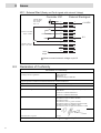
1
Operating Manual
Bedienungsanleitung
LED Flood Controller
Steuergerät LED Flächenstrahler
97104
Contents
1
1.1
1.2
1.3
1.4
Please observe the following.......................................................................................... 3
Emphasized Sections........................................................................................................ 3
Items Supplied.................................................................................................................. 3
Field of Application (Intended Usage)............................................................................. 3
For Your Safety................................................................................................................ 4
2 Descri ption ...................................................................................................................... 5
2.1
Theory of Operation ......................................................................................................... 5
Interface and Connections..................................................................................................
2.2
3 T echnical Data ................................................................................................................ 7
4 Installation ...................................................................................................................... 8
Environmental and Operating Conditions........................................................................ 8
4.1
4.2
Space Requirements ......................................................................................................... 8
Connecting the Unit ......................................................................................................... 8
4.3
5 Cu ring.............................................................................................................................. 9
5.1
Setting into Operation ...................................................................................................... 9
Adjusting the Curing Time............................................................................................... 9
5.2
5.2.1
Time Controlled Mode..................................................................................................... 9
5.2.2
Continuous Mode ............................................................................................................ 9
Shutdown for Periods of Non-use .................................................................................. 10
5.3
5.4
Returning to Operation after Periods of Non-use .......................................................... 10
6
Care and Maintenance................................................................................................. 10
7 Troubleshooting ............................................................................................................ 10
8 A nnex............................................................................................................................. 11
8.1
Spare Parts...................................................................................................................... 11
Pin Assignment .............................................................................................................. 11
8.2
8.3
Declaration of Conformity ............................................................................................. 12
8.4
Warranty (only for US market) ...................................................................................... 13
2
1
1.1
Please observe the following
Emphasized Sections
Warning!
Refers to safety regulations and requires safety measures that protect the operator or other persons
from injury or danger to life.
Caution!
Emphasizes what must be done or avoided so that the unit or other property
is not damaged.
☞
Notice
Gives recommendations for better handling or adjustment of the unit during operation as well as
for service activities.
The numbers printed in bold in the text refer to the corresponding position numbers in the
illustration on page 6-7.
• The point emphasizes an instruction step.
Instruction steps in the illustrations are
indicated with arrows.
When several instruction steps are indicated
in an illustration, the shading of the arrow
has the following meaning:
Black arrow = 1st step
Grey arrow = 2nd step
White arrow = 3rd step
1.2
Items Supplied
1 LED Flood Controller Type 97104, Order no. 1359255
1 Power Cord
1 Operating Manual
Additional Items Required
1 LED Head
– 375 nm Array, Order no. 1167582
– 405 nm Array, Order no. 1167593
– Indigo™ Array, Order no. 1167589
1 LED Power Cable, Order no. 1333333
☞
1.3
Notice
As a result of technical development, the illustrations and descriptions in this instruction manual
can deviate in detail from the actual unit delivered.
Field of Application (Intended Usage)
The Loctite LED Flood Systems, 375, 405 and Indigo are designed for use with light cure
products that cure when exposed to ultraviolet and/or visible light. The system can be operated
manually, operated with the integrated timer, or controlled with an external switch. The system
is designed for intermittent or constant duty cycle.
3
1
1.4
Please observe the following
For Your Safety
For safe and successful operation of the unit, read these instructions completely. The
manufacturer cannot be held responsible for damage or injury of any kind because of misuse or
improper application or because of failure to observe safety instructions or warnings.
Be sure to retain this manual for future reference.
Request the technical data sheet and the safety data sheet for the
LOCTITE® product used at
www.loctite.com for US and Canada version of data sheets.
FOLLOW UNCONDITIONALLY THE INSTRUCTIONS OF THESE DATA SHEETS!
WARNING!
It is the responsibility of the user to ensure that all devices being driven by the LED Flood
Controller are set-up in a safe manner.
The manufacturer is in no way responsible for injuries or damage to persons or property resulting
from devices being driven by the LED Flood Controller.
For safe and successful operation of the unit, read these instructions completely. If the instructions
are not observed, the manufacturer can assume no responsibility.
Removing, bypassing or putting out of operation of the safety devices can result in radiation
damage to persons and damage to the unit and is therefore prohibited!
Do not look directly at LED-UV light, or at LED-UV light reflected in a mirror or other reflective
surface. Doing so could cause eye damage.
Install the LED head in a way that humans are not exposed to LED-UV light.
Exposure could injure the skin or cause other injury.
If there is a risk of the LED-UV light being exposed to UV reflective light, place the product inside a
cover with proper reflectance and heat characteristics to block that reflected light.
When operating the controller, set up the system so that the path of the LED-UV light is not at eye
level.
It is strongly recommended to place a protective barrier around the product so that people cannot
approach it while it is operating.
Wear protective UV glasses and other protective clothing during operation.
Never operate this product in a manner not described in this manual. Doing so risks exposure to LEDUV light.
Damage to the power cord or the housing can result in contact with live electrical parts. Check the
power cord and the unit before each use. If the power cord or the unit is damaged, do not operate!
Replace a damaged power cord with a new one.
The unit may be opened and repaired only by authorized service personal.
4
2
2.1
Description
Theory of Operation
The LED Flood Controller provides electrical power to the LED’s through the connecting cable
(not included).
Indicator lights located on the front panel of the power supply provide visual confirmation that the
LED’s are in or out of their acceptable range. In the event of temperature fault the power supply
will automatically shut down to protect the LED array.
When the cure cycle is initiated, light is immediately irradiated at or near maximum intensity
from the LED’s.
The curing process begins when the adhesive is placed under the LED’s. The two primary
variables that control the curing process are the time of exposure and the strength of the light
(irradiance). For a given irradiance, the exposure time required to fully cure the adhesive depends
primarily on the properties of the adhesive and the optical properties of the substrate that the light
is transmitted through
Ready
If the dispensing cycle is finished and no fault occurs, this contact closes.
Fault
The start of a curing cycle via the key Start is not locked when Fault is indicated.
It is locked when the start is triggered via the interface XS 1 (Footswitch or external signal from a
higher-ranking controller).
Both signals are available as dry contacts at the XS 1 start interface for optional connection to a
higher-ranking controller or a warning light, see section 8.2.
5
2
2.2
Description
Displays, operating elements and connections
1
2
3
4
CONT
CONT
5
Power
Start
Enter
Cure Light ON
Overheat
9
7
6
1
2
3
4
5
6
LED “CONT - The lighting of the red LED “CONT“ indicates Continuous mode.
Digital Display - Three-figure Display of the curing time [s].
Indication LED “Power” (green). Indicates power on.
Indication LED “Cure Light ON” (blue). Indicates the lightning of the LED Head.
Indication LED “Overheat” (red). Indicates an overheat error of the LED Head.
Power Switch 1/0 (ON/OFF)
7
Key Enter
Key for the storing of the new values set for the curing time [s].
When the indication of the curing time [s] in the digital display blinks, the indicated
curing time is stored by pressing button and the display stops blinking.
Keys
and
Buttons for changing the curing time for a curing sequence.
When button
or
is pressed, the display of the curing time [s] in the digital display
begins to blink. The curing time is adjustable from 0.01 to 99.9 s.
Buttons for switching from time controlled mode to continuous mode.
With the simultaneous pressing of the buttons for more than 0.5 seconds, an operating
mode change takes place to the Continuous mode. In the display, “con” appears. The
lighting of the LED “CONT.“ indicates Continuous mode.
During curing, the elapsed curing time is indicated in the digital display beginning each
time with 0.00 s. The last curing time remains displayed until the next start.
– Switching back to time controlled mode without storage of the curing time by renewed
pressing of keys
or
. The LED extinguishes. In the digital display, the curing time
is blinking.
– Switching back to time controlled mode with storage of the curing time by pressing
key Enter . The LED extinguishes. The indicated curing time is stored.
Key Start
Key for starting a curing sequence. The LED lights for the duration of the curing
sequence.
The curing time in time controlled mode corresponds to the value on the digital display
and is independent of the length of time that button is pressed.
In continuous mode, the product is cured as long as key is pressed.
8
9
6
8
2
Description
10
11
90-260 VAC
47-63 Hz
5 AT
Power Consumption
max. 350 W
Henkel Corporation, Rocky
Hill
1001 Trout Brook Crossing
Rocky Hill, CT 06067
United States
Type No. 97104
Order No. 1359255
XS1 Start
Place for Serial No. Sticker
Made in Germany
XS3 LED Head
14
10
11
12
13
14
3
13
12
Power Fuse, 5 A time-lag, glass type 5x20 mm
Socket XS 1: Start
The footswitch is connected here. It is also the output for the READY and FAULT signals.
Socket XS 3: LED Head
15 pin Sub D Connection to the LED Head Array.
Fan
Power Supply Socket
To be ordered separately and not shown:
Safety glasses orange, order nr. 1175128, shall be used with LED head Indigo and 405 nm;
Safety glasses grey, order no. 1175127, shall be used with LED head 375 nm and 405 nm.
Technical Data
Power supply
Power consumption
Power protection
Internal control voltage
Power connection
Dimensions W x H x D
Weight
Operating Temperature
Storage Temperature
Continuous noise level
Power supply 90 – 260 V AC; 47 – 63 Hz
Approx. 350 W
Glass tube, fine wire fuse, 5 A semi time-lag
24 V DC
Cold appliance coupling IEC 320 acc. to VDE 0625
12.2x5.3x14.4 inch (310x135x365 mm)
Approx. 3.5 kg (7.7 lbs)
+10 °C to +40 °C (+50 °F to +104 °F)
-10 °C to +60 °C (+14 °F to +140 °F)
< 30 dB(A)
7
4
4.1
Installation
Environmental and Operating Conditions
– No direct sunlight; no UV light.
– No condensing humidity.
– No splash water.
4.2
Space Requirements
min. 4” (min. 100 mm)
Freiraum für
Kabel und Luft für
Ventilator.
5.2” (132 mm)
CONT
Area to be left
clear for cables
and air for fan.
CONT
Power
Cure Light ON
Start
14.2“ (360 mm)
4.3
Enter
Overheat
11.9“ (302 mm)
Connecting the Unit
• Connect Sub D 9 pin connector of the footswitch 97201 or a higher-ranking controller to XS 1.
• Connect the 15 pin Sub D connector to the LED Head Array to XS 3.
• Connect power cord to the appropriate plug.
90-260 VA
C
47-63 Hz
Power Co
nsumption
max. 350
W
1 Start
Henkel Cor
poration,
Roc
1001 Trou
t Brook Cro ky Hill
ssing
Rocky Hill,
CT
United Stat 06067
es
Type No.
97104
Order No
. 1359255
Place for
Serial No.
Made in Germ
Head
8
any
Sticker
5
5.1
Curing
Setting into Operation
CAUTION!
Observe the operating manuals of the LED Head used.
Switch the power switch 6 to position 1 (ON).
5.2
5.2.1
Adjusting the Curing Time
Time Controlled Mode
This mode of operation is used for curing applications with the same curing time.
• With keys
or
set the curing time to
1.50 s. The indication of the curing time in
the digital display begins blinking.
CONT
CONT
Start
When the curing time for the application quantity is roughly achieved:
• Set the exact dispensed quantity by changing the curing time with keys
• Press the footswitch to check the result of the curing cycle.
Enter
or
.
Storing of the curing time setting.
• Press key Enter . The indication of the curing time in the digital display stops blinking.
5.2.2
Continuous Mode
This mode of operation is used for applications with different times.
• Press the keys
and
simultaneously.
The lighting of the LED “CONT.“ indicates
Continuous mode. The display of the
dispensing time in the digital display is set
to con.
• Press the key Start (or the foot switch) to
check if the product is cured.
CONT
CONT
Start
Enter
– Switching back to time controlled mode without storage of the curing time by renewed pressing
of keys
or
. The LED extinguishes. In the digital display, the curing time is blinking.
– Switching back to time controlled mode with storage of the curing time by
pressing key Enter . The LED extinguishes. The indicated curing time is stored.
9
5
5.3
Curing
Shutdown for Longer Periods of Non-use
• Switch off the controller.
5.4
Returning to Operation after Longer Periods of Non-use
• Check the installation according to Chapter 4.
• Switch on the controller.
6
Care and Maintenance
The unit requires no special care and maintenance.
CAUTION!
Observe the operating manuals of the LED Head used.
7
Troubleshooting
In case of any error, the 3 digit display of the timer board shows alternate blinking “E” and the
LED, which corresponds to the error lights or extinguishes.
Type of Error
Display
Possible Causes
Corrections
LED overvoltage
(measured during
irradiation)
– Alternate blinking “E”
and cure time in the
3 digit display – sum
error only
– LED head electrical
damaged.
• Henkel Service
– LED head connection
cord damaged
• Check and change cord.
Wire break.
LED lamp head fan failure
Controller housing fan
failure
– Fan damaged or obstacles • Check, if filter pad is
maybe sucked in.
broken. Remove possible
obstacles and change filter
pad
Power failure
– Green LED “Power” off – Controller overheated.
and alternate blinking “E”
and cure time in the
3 digit display
• Switch off controller and
wait longer then 3 minutes
for cooling down. If error
appears again – Henkel
Service.
LED head overheated
– Red LED “Overheat” on – LED head too hot.
and alternate blinking “E”
and cure time in the
3 digit display
• Do not switch off the
system, because the fans
have to run for cooling the
units till red led “Overheat
extinguishes. If error
appears again – Henkel
Service
10
8
8.1
Annex
Spare Parts and Accessories
Item Description
Type No.
– LED Head 375 nm Array.......................................................
8.2
Order Code No.
1167582
–
LED Head 405 nm Array.......................................................
1167593
–
LED Head Indigo™ Array.....................................................
1167589
–
LED Power Cable ..................................................................
1333333
–
UV Protection Glasses, grey..................................................8953426
1175127
–
UV Protection Glasses, orange ..............................................8953427
1175128
–
UV Protection Gloves, cotton................................................984070
376746
–
Footswitch..............................................................................97201
88653
Pin Assignment
XS 1: Start Footswitch (Ready and Fault signals with internal Voltage)
Controller XS1
Internal relays:
max. 30 VDC
max. 30 W,
max. 1 A
Closed = No Fault
Open = FAULT
Footswitch
4
1
3
Start 1
1
2
2
3
3
4
4
5
5
6
6
2
2
Closed = Ready
GND
S1
1
Closed = FAULT
Open = No Fault
+ 24V
output
7
7
8
8
9
9
Never connect external voltage on pin 5 or pin 9!
11
8
Annex
XS 1: External Start (Ready and Fault signals with external Voltage)
Controller XS1
Internal relays:
max. 30 VDC
max. 30 W,
max. 1 A
Closed = No Fault
Open = FAULT
External Startsignal
4
1
3
Start 1
1
2
2
3
3
4
4
5
5
6
6
7
7
8
8
9
9
2
+ 24 VDC
Closed = Ready
GND
Closed = FAULT
Open = No Fault
+ 24V
output
0V
Never connect external voltage on pin 9!
8.3
Declaration of Conformity
Declaration of Conformity
The Manufacturer
according to the EC regulations
Henkel AG & Co. KGaA
Standort München
Gutenbergstr. 3
D-85748 Garching bei München
declares that the unit designated in the following is, as a result of its design and construction, in accordance with the
European regulations, harmonized standards and national standards listed below.
Designation of the unit
LED Flood Controller Type 97104
Unit number
1359255
Applicable EC Regulations
EC Directive for Electro-Magnetic Compatibility
2004/108/EG
EC Directive of RoHS 2002/95/EG
EC Directive of WEEE 2002/96/EG
EN 55011:2007+A2:2007; EN 61000-3-2:2006;
EN 61000-3-3:1955+A1:2001+A2:2005;
EN 61000-6-2:2005;
EN 61000-4-2:1995+A1_1998+A2:2001;
EN 61000-4-3:2006+A1:2008; EN 61000-4-4:2004;
EN61000-4-5:2006; EN 61000-4-6:2007;
EN 61000-4-8:1993+A1:2001; EN 61000-4-11:2004
Applicable harmonized standards
Date/Manufacturer’s signature
29th Sep 2009
(Dr. W. Fleischmann)
This declaration is not valid if there are any changes not approved by Henkel.
12
8
8.4
Annex
Warranty (only for US market)
Henkel expressly warrants that all products referred to in this Instruction Manual for the LED Flood Systems (hereafter called
“Products”) shall be free from defects in materials and workmanship. Liability for Henkel shall be limited, as its option, to
replacing those Products which are shown to be defective in either materials or workmanship or to credit the purchaser the
amount of the purchase price thereof (plus freight and insurance charges paid therefore by the user). The purchaser’s sole and
exclusive remedy for breach of warranty shall be such replacement or credit.
A claim of defect in materials or workmanship in any Products shall be allowed only when it is submitted in writing within
one month after discovery of the defect or after the time the defect should reasonably have been discovered and in any event,
within (12) months after the delivery of the Products to the purchaser. This warranty does not apply to perishable items, such
as fuses, filters, lights, etc. No such claim shall be allowed in respect of products which have been neglected or improperly
stored, transported, handled, installed, connected, operated, used or maintained. In the event of unauthorized modification of
the Products including, where products, parts or attachments for use in connection with the Products are available from
Henkel, the use of products, parts or attachments which are not manufactured by Henkel, no claim shall be allowed.
No Products shall be returned to Henkel for any reason without prior written approval from Henkel. Products shall be
returned freight prepaid, in accordance with instructions from Henkel.
NO WARRANTY IS EXTENDED TO ANY EQUIPMENT WHICH HAS BEEN ALTERED, MISUSED, NEGLECTED,
OR DAMAGED BY ACCIDENT.
EXCEPT FOR THE EXPRESS WARRANTY CONTAINED IN THIS SECTION, HENKEL MAKES NO WARRANTY
OF ANY KIND WHATSOEVER, EXPRESS OR IMPLIED, WITH RESPECT TO THE PRODUCTS.
ALL WARRANTIES OF MERCHANTABILITY, FITNESS FOR A PARTICULAR PURPOSE, AND OTHER
WARRANTIES OF WHATEVER KIND (INCLUDING AGAINST PATENT OR TRADEMARK INFRINGEMENT) ARE
HEREBY DISCLAIMED BY HENKEL AND WAIVED BY THE PURCHASER.
THIS SECTION SETS FORTH EXCLUSIVELY ALL OF LIABILITY FOR HENKEL TO THE PURCHASER IN
CONTRACT, IN TORT OR OTHERWISE IN THE EVENT OF DEFECTIVE PRODUCTS.
WITHOUT LIMITATION OF THE FOREGOING, TO THE FULLEST EXTENT POSSIBLE UNDER APPLICABLE
LAWS, HENKEL EXPRESSLY DISCLAIMS ANY LIABILITY WHATSOEVER FOR ANY DAMAGES INCURRED
DIRECTLY OR INDIRECTLY IN CONNECTION WITH THE SALE OR USE OF, OR OTHERWISE IN
CONNECTION WITH, THE PRODUCTS, INCLUDING, WITHOUT LIMITATION, LOSS OF PROFITS AND
SPECIAL, INDIRECT OR CONSEQUENTIAL DAMAGES, WHETHER CAUSED BY NEGLIGENCE FROM
HENKEL OR OTHERWISE.
13
Inhaltsverzeichnis
1
1.1
1.2
1.3
1.4
Bitte beachten Sie ......................................................................................................... 15
Hervorhebungen ............................................................................................................. 15
Lieferumfang.................................................................................................................. 15
Einsatzbereich (Bestimmungsgemäße Verwendung)..................................................... 15
Zu Ihrer Sicherheit ......................................................................................................... 16
2 G erätebeschreibung ..................................................................................................... 17
Funktionsbeschreibung .................................................................................................. 17
2.1
2.2
Schnittstellen und Anschlüsse........................................................................................ 18
3 Te chnische Daten ......................................................................................................... 19
4 Installation .................................................................................................................... 20
4.1
Umgebungs- und Betriebsbedingungen ......................................................................... 20
Platzbedarf...................................................................................................................... 20
4.2
4.3
Anschließen des Gerätes ................................................................................................ 20
5 A ushärtung ................................................................................................................... 21
5.1
Betrieb ............................................................................................................................ 21
5.2
Einstellen der Aushärtezeit ............................................................................................ 21
5.2.1
Zeitgesteuerten Betrieb .................................................................................................. 21
Dauerbetrieb ................................................................................................................... 21
5.2.2
5.3
Längere Stilllegung der Anlage ..................................................................................... 22
5.4
Erneute Inbetriebnahme nach Stilllegung ...................................................................... 22
6
Pflege und Wartung ..................................................................................................... 22
7 Be seitigung von Störungen .......................................................................................... 22
8 A nhang .......................................................................................................................... 23
Ersatzteile und Zubehör ................................................................................................. 23
8.1
8.2
Steckerbelegung ............................................................................................................. 23
8.3
EU-Konformitätserklärung ............................................................................................ 24
14
1
1.1
Bitte beachten Sie
Hervorhebungen
Warnung!
Verweist auf Sicherheitsvorschriften und fordert Vorsichtsmaßnahmen, die den Betreiber des
Gerätes oder andere Personen vor Verletzungs- oder Lebensgefahr schützen.
Achtung!
Hebt hervor, was getan oder unterlassen werden muss, um das Gerät oder andere Sachwerte nicht
zu beschädigen.
☞
Hinweis
Gibt Empfehlungen zum besseren Handhaben des Gerätes bei Bedien- und Einstellvorgängen
sowie Pflegearbeiten.
Die fett gedruckten Zahlen im Text beziehen sich auf die entsprechende Positionsnummer in der
Abbildung auf Seite 18-19.
• Der Punkt hebt einen Handlungsschritt
hervor.
Handlungsschritte in den Abbildungen sind
durch Pfeile gekennzeichnet.
Werden mehrere Handlungsschritte in einer
Abbildung dargestellt, bedeutet ein:
Schwarzer Pfeil = 1..Schritt
Grauer Pfeil
= 2..Schritt
Weißer Pfeil
= 3..Schritt
1.2
Lieferumfang
1 Steuergerät LED Flächenstrahler 97104, Bestell-Nr. 1359255
1 Netzkabel
1 Bedienungsanleitung
Zusätzlich erforderliches Zubehör
1 LED-Kopf
– 375 nm Array, Bestell-Nr. 1167582
– 405 nm Array, Bestell-Nr. 1167593
– Indigo™ Array, Bestell-Nr. 1167589
1 LED Netzkabel, Bestell-Nr. 1333333
☞
Hinweis
Entwicklungsbedingt können die Abbildungen und Beschreibungen in diesem Handbuch in
Einzelheiten von dem tatsächlich gelieferten Gerät abweichen.
1.3
Einsatzbereich (Bestimmungsgemäße Verwendung)
Die Loctite LED Lampensysteme 375, 405 und Indigo™ werden für lichthärtende Produkte
eingesetzt, die durch Bestrahlung mit ultraviolettem / sichtbarem Licht ausgehärtet werden. Das
Gerät kann manuell betrieben oder über den integrierten Zeitmesser oder einen externen Schalter
angesteuert werden. Es ist für den Aussetz- oder Dauerbetrieb ausgelegt.
15
1
1.4
Bitte beachten Sie
Zu Ihrer Sicherheit
Für den gefahrlosen und erfolgreichen Einsatz des Gerätes diese Anleitung vollständig lesen.
Der Hersteller ist in keiner Weise verantwortlich für Sach- oder Personenschäden, die infolge
der Nutzung abweichend vom bestimmungsgemäßen Gebrauch oder der Nichtbeachtung von
Sicherheitshinweisen oder Warnungen verursacht werden.
Bewahren Sie diese Anleitung nach Durchsicht griffbereit auf.
Das Technische Datenblatt und das Sicherheitsdatenblatt für das eingesetzte LOCTITE® Produkt
anfordern bei:
www.loctite.com. Hier erhalten Sie die amerikanische und kanadische Version der Datenblätter.
ANWEISUNGEN IN DIESEN DATENBLÄTTERN UNBEDINGT BEFOLGEN!
WARNUNG!
Der Anwender selbst ist dafür verantwortlich, dafür zu sorgen, dass alle durch das Steuergerät
LED Flächenstrahler angetriebenen Geräte sicher aufgestellt werden.
Der Hersteller ist in keiner Weise verantwortlich für Sach- oder Personenschäden, die durch
Geräte entstehen, welche von dem Steuergerät LED Flächenstrahler angetriebenen werden.
Für den gefahrlosen und erfolgreichen Einsatz des Gerätes diese Anleitung vollständig lesen.
Werden die Anweisungen nicht befolgt, übernimmt der Hersteller keine Garantie.
Entfernen, Überbrücken oder Außerkraftsetzen der Sicherheitseinrichtungen kann zu
Strahlenschäden bei Personen und zu Schäden am Gerät führen und ist deshalb verboten!
Nicht direkt in die LED-UV Lichtquelle oder in LED-UV-Licht blicken, das über einen Spiegel oder
eine andere reflektierende Oberfläche reflektiert wird. Es besteht sonst die Gefahr von Augenschäden.
LED-Kopf so anbringen, dass das LED-UV-Licht nicht auf Menschen einwirkt.
Die Bestrahlung könnte zu Hautverletzungen oder anderen Schäden führen.
Wenn die Gefahr besteht, dass das LED-UV-Licht durch eine UV-Lichtquelle reflektiert wird,
sollte das Gerät in eine Abdeckung mit geeignetem Reflexions- und Wärmeschutz gestellt
werden, um dieses reflektierte Licht abzuschirmen.
Für den Betrieb des Steuergerätes das System so aufstellen, dass der Strahlengang des LED-UV-Lichts
nicht in Augenhöhe verläuft.
Es wird unbedingt empfohlen, eine Schutzbarriere um das Gerät anzubringen, damit sich
Menschen während des Betriebs nicht nähern können.
Während des Betriebes UV-Schutzbrille und andere Schutzkleidung tragen.
Das System niemals anders als in diesem Handbuch beschrieben in Betrieb nehmen. Sonst besteht die
Gefahr der Einwirkung von LED-UV-Licht.
Bei Schäden am Netzkabel oder Gehäuse kann es zu Berührungen spannungsführender Teile kommen.
Vor jedem Gebrauch Netzkabel und Gerät kontrollieren. Bei beschädigtem Netzkabel oder Gerät nicht
in Betrieb nehmen! Das beschädigte Netzkabel durch ein neues ersetzen.
Das Gerät darf nur von autorisiertem Servicepersonal geöffnet und repariert werden.
16
2
2.1
Gerätebeschreibung
Funktion
Das Steuergerät LED Flächenstrahler versorgt die LEDs über das Anschlusskabel (nicht im
Lieferumfang enthalten) mit elektrischer Energie.
Anzeigelampen auf der Vorderseite dienen zur visuellen Bestätigung, ob die LED-Werte innerhalb
oder außerhalb des zulässigen Bereichs liegen. Im Falle einer Temperaturstörung wird die
Stromversorgung automatisch abgeschaltet, um die LED-Zeile zu schützen.
Wenn der Aushärtezyklus gestartet wird, strahlen die LEDS sofort Licht mit maximaler oder nahezu
maximaler Intensität ab.
Der Aushärtevorgang beginnt, wenn der Klebstoff unter den LEDs platziert wird. Der
Aushärtevorgang wird hauptsächlich von zwei Variablen bestimmt: der Bestrahlungszeit und der
Lichtstärke (Bestrahlungsstärke). Bei einer bestimmten Bestrahlungsstärke ist die für die vollständige
Aushärtung des Klebstoffes erforderliche Bestrahlungszeit in erster Linie abhängig von den
Eigenschaften des Klebstoffes und den optischen Eigenschaften des Materials, das von dem
einfallenden Licht durchdrungen wird.
Bereit
Wenn der Dosierzyklus beendet und kein Fehler aufgetreten ist, schließt dieser Kontakt.
Fehler
Der Start des Aushärtevorgangs über die Taste Start ist nicht gesperrt, wenn ein Fehler angezeigt wird.
Er ist gesperrt, wenn der Start über die Schnittstelle XS 1 (Fußschalter oder externes Signal von einer
übergeordneten Steuerung) ausgelöst wird.
Beide Signale sind als potentialfreie Kontakte an der XS 1 Start-Schnittstelle verfügbar, als optische
Anschlussmöglichkeit an eine übergeordnete Steuerung oder ein Warnlicht, siehe Abschnitt 8.2.
17
2
2.2
Gerätebeschreibung
Anzeigen, Bedienelemente und Anschlüsse
1
2
3
4
CONT
CONT
5
Power
Start
Enter
Cure Light ON
Overheat
9
7
6
1
2
3
4
5
6
LED “CONT - Leuchten der roten LED “CONT“ zeigt Dauerbetrieb an.
Digitalanzeige - Dreistellige Anzeige der Aushärtezeit [s].
Anzeige-LED “Ein” (grün). Zeigt an, dass das Gerät eingeschaltet ist.
Anzeige-LED “Cure Light ON” (blau). Zeigt an, dass der LED-Kopf Licht emittiert.
Anzeige-LED “Overheat” (rot). Zeigt einen Überhitzungsfehler des LED-Kopfes an.
Netzschalter 1/0 (EIN/AUS)
7
Taste Enter
Taste zum Speichern der neuen Einstellwerte für die Aushärtezeit [s].
Wenn die Anzeige der Aushärtezeit [s] in der Digitalanzeige blinkt, wird die angezeigte
Aushärtezeit durch Drücken der Taste gespeichert, und die Anzeige hört auf zu blinken.
und
Tasten
Tasten zum Ändern der Aushärtezeit für einen Aushärtetakt.
Wenn Taste
oder
gedrückt wird, beginnt die Anzeige der Aushärtezeit [s] in der
Digitalanzeige zu blinken. Die Aushärtezeit ist einstellbar von 0,01 bis 99,9 s.
Tasten zum Umstellen vom zeitgesteuerten Betrieb auf Dauerbetrieb.
Gleichzeitiges Drücken der Tasten für mehr als 0,5 Sekunden bewirkt eine Umstellung der
Betriebsart auf Dauerbetrieb. In der Anzeige erscheint “con”. Durch das Leuchten der LED
“CONT.“ wird der Dauerbetrieb angezeigt.
Während der Aushärtung wird die abgelaufene Aushärtezeit in der Digitalanzeige angezeigt;
sie beginnt jedes Mal bei 0,00 s. Die letzte Aushärtezeit bleibt bis zum nächsten Start
angezeigt.
– Zurückschalten zum zeitgesteuerten Betrieb ohne Speicherung der Aushärtezeit durch
erneutes Drücken der Tasten oder
. Die LED erlischt. In der Digitalanzeige blinkt die
Aushärtezeit.
– Zurückschalten zum zeitgesteuerten Betrieb mit Speicherung der Aushärtezeit durch
Drücken der Taste Enter . Die LED erlischt. Die angezeigte Aushärtezeit wird gespeichert.
Taste Start
Taste für den Start eines Aushärtetakts. Die LED leuchtet während der gesamten Dauer
des Aushärtetaktes.
Die Aushärtezeit im zeitgesteuerten Betrieb entspricht dem Wert auf der Digitalanzeige
und ist abhängig davon, wie lange die Taste gedrückt wird.
Im Dauerbetrieb wird das Produkt so lange ausgehärtet, wie die Taste gedrückt wird.
8
9
18
8
2
Gerätebeschreibung
10
11
90-260 VAC
47-63 Hz
5 AT
Power Consumption
max. 350 W
Henkel Corporation, Rocky
Hill
1001 Trout Brook Crossing
Rocky Hill, CT 06067
United States
Type No. 97104
Order No. 1359255
XS1 Start
Place for Serial No. Sticker
Made in Germany
XS3 LED Head
14
10
11
12
13
14
3
13
12
Netzsicherung, 5 A träge, Glasrohr 5x20 mm
Buchse XS 1: Start
Hier wird der Fußschalter angeschlossen. Dies ist auch der Ausgang für die Bereit- und
Fehlermeldung.
Buchse XS 3: LED-Kopf
15-poliger Sub-D-Anschluss für die LED-Zeile.
Lüfter
Netzanschlussbuchse
Separat zu bestellen und hier nicht dargestellt:
Schutzbrille orange, Bestell-Nr. 1175128, zur Verwendung bei Einsatz von LED-Kopf
IndigoTM und 405 nm;
Schutzbrille grau, Bestell-Nr. 1175127, zur Verwendung bei Einsatz von LED-Kopf 375 nm
und 405 nm.
Technische Daten
Stromversorgung
Stromaufnahme
Netzsicherung
Interne Steuerspannung
Stromanschluss
Abmessungen B x H x T
Gewicht
Betriebstemperatur
Lagertemperatur
Dauerschalldruckpegel
Netzanschluss 90 – 260 V AC; 47 – 63 Hz
ca. 350 W
Glasrohr-Feinsicherung, 5 A mittelträge
24 V/DC
Kaltgerätesteckdose IEC 320 gem. VDE 0625
12.2x5.3x14.4 inch (310x135x365 mm)
ca.. 3.5 kg (7.7 lbs)
+10 °C to +40 °C (+50 °F to +104 °F)
-10 °C to +60 °C (+14 °F to +140 °F)
< 30 dB(A)
19
4
4.1
Installation
Umgebungs- und Betriebsbedingungen
– Direkte Sonnen- und UV-Lichteinstrahlung vermeiden.
– Keine kondensierende Feuchtigkeit.
– Kein Spritzwasser.
4.2
Platzbedarf
min. 4” (min. 100 mm)
Freiraum für
Kabel und Luft für
Ventilator.
5.2” (132 mm)
CONT
Area to be left
clear for cables
and air for fan.
CONT
Power
Cure Light ON
Start
14.2“ (360 mm)
4.3
Enter
Overheat
11.9“ (302 mm)
Anschließen des Gerätes
• 9-poligen Sub-D-Anschluss des Fußschalters 97201 oder übergeordnete Steuerung an XS 1 Start
anschließen.
• 15-poligen Sub-D-Anschluss für die LED-Zeile an XS3 anschließen.
• Netzkabel an vorgesehene Buchse anschließen
90-260 VA
C
47-63 Hz
Power Co
nsumption
max. 350
W
1 Start
Henkel Cor
poration,
Roc
1001 Trou
t Brook Cro ky Hill
ssing
Rocky Hill,
CT
United Stat 06067
es
Type No.
97104
Order No
. 1359255
Place for
Serial No.
Made in Germ
Head
20
any
Sticker
5
5.1
Aushärtung
Betrieb
ACHTUNG!
Bedienungsanleitung für den eingesetzten LED-Kopf beachten.
Netzschalter 6 auf Position I (EIN) stellen.
5.2
5.2.1
Einstellen der Aushärtezeit
Zeitgesteuerter Betrieb
Diese Betriebsart wird für Aushärteanwendungen mit einheitlicher Aushärtezeit eingesetzt.
• Aushärtezeit mit den Tasten
oder
auf
1,50 s stellen. Die Anzeige der Aushärtezeit in
der Digitalanzeige beginnt zu blinken.
CONT
CONT
Start
Enter
Wenn die Aushärtezeit für die Dosiermenge in etwa erreicht ist:
• Genaue Dosiermenge durch Ändern der Aushärtezeit mit den Tasten
oder
• Fußschalter betätigen, um das Ergebnis des Aushärtevorgangs zu überprüfen.
einstellen.
Speichern der Einstellung für die Aushärtezeit.
• Taste Enter drücken. Die Anzeige der Aushärtezeit in der Digitalanzeige hört auf zu blinken.
5.2.2
Dauerbetrieb
Diese Betriebsart wird für Anwendungen mit unterschiedlichen Zeiten eingesetzt.
• Die Tasten
und
gleichzeitig drücken.
Durch das Leuchten der LED “CONT.“ wird
der Dauerbetrieb angezeigt. In der
Digitalanzeige wird die Anzeige für die
Dosierzeit als "con" dargestellt.
• Taste Start drücken (oder Fußschalter
betätigen), um zu überprüfen, ob das Produkt
ausgehärtet wird.
CONT
CONT
Start
Enter
– Zurückschalten zum zeitgesteuerten Betrieb ohne Speicherung der Aushärtezeit durch erneutes
Drücken der Tasten
oder
. Die LED erlischt. In der Digitalanzeige blinkt die Aushärtezeit.
– Zurückschalten zum zeitgesteuerten Betrieb mit Speicherung der Aushärtezeit durch Drücken der
Taste Enter . Die LED erlischt. Die angezeigte Aushärtezeit wird gespeichert.
21
5
5.3
Aushärtung
Längere Stilllegung der Anlage
• Gerät ausschalten.
5.4
Erneute Inbetriebnahme nach längerer Stilllegung
• Installation gemäß Abschnitt 4 überprüfen.
• Gerät einschalten.
6
Pflege und Wartung
Das Gerät bedarf keiner besonderen Pflege und Wartung.
ACHTUNG!
Bedienungsanleitung für den eingesetzten LED-Kopf beachten.
7
Beseitigung von Störungen
Bei Auftreten eines Fehlers wird in der 3-stelligen Zeit-Anzeige abwechselnd ein blinkendes "E"
angezeigt, und die entsprechende LED leuchtet oder geht aus.
Fehlerart
Anzeige
Mögliche Ursachen
Abhilfe
LED Überspannung
(während der Bestrahlung
gemessen)
– Abwechselndes Blinken
von “E” und Aushärtezeit
in der dreistelligen
Anzeige – nur
Summenfehler
– LED-Kopf elektrisch
beschädigt
• Henkel Service
– LED-KopfVerbindungskabel
beschädigt
• Prüfen und Kabel
auswechseln.
– Lüfter beschädigt, oder
Hindernisse eingesaugt.
• Prüfen ob Filtermatte
beschädigt ist. Eventuelle
Hindernisse entfernen und
Filtermatte auswechseln.
Drahtbruch
Versagen des LED-KopfLüfters
Versagen des
Steuerungsgehäuse-Lüfters
Stromausfall
– Grüne LED “Power” aus
und abwechselndes
Blinken von “E” und
Aushärtezeit in der
dreistelligen Anzeige
– Steuergerät überhitzt.
• Steuergerät ausschalten und
mehr als 3 Minuten
abkühlen lassen. Wenn
Fehler wieder auftritt –
Henkel Service.
LED-Kopf überhitzt
– Rote LED “Overheat” an
und abwechselndes
Blinken von “E” und
Aushärtezeit in der
dreistelligen Anzeige
– LED-Kopf zu heiß.
• Gerät nicht abschalten, weil
die Lüfter noch weiter
laufen müssen, um das
Gerät abzukühlen, bis die
rote LED “Overheat”
ausgeht. Wenn Fehler
wieder auftritt – Henkel
Service
22
8
8.1
Anhang
Ersatzteile und Zubehör
Pos.
–
–
–
–
–
–
–
–
8.2
Bezeichnung
Pr. Nr.
LED-Kopf 375 nm Array ...........................................................–
LED-Kopf 405 nm Array ...........................................................–
LED-Kopf Indigo™ Array .........................................................–
LED Netzkabel ..........................................................................–
UV-Schutzbrille grau ................................................................ 8953426
UV-Schutzbrille orange..............................................................8953427
UV-Schutzhandschuhe, Baumwolle...........................................984070
Fußschalter .................................................................................97201
Bestell-Nr.
1167582
1167593
1167589
1333333
1175127
1175128
376746
88653
Steckerbelegung
XS 1: Start Fußschalter (Bereit- und Fehlermeldung mit interner Spannung)
Steuergerät XS1
Interne Relais:
max. 30 VDC
max. 30 W,
max. 1 A
Geschlossen = Kein Fehler
Geöffnet = Fehler
Fußschalter
4
1
3
Start 1
1
2
2
3
3
4
4
5
5
6
6
7
7
8
8
9
9
2
2
Geschlossen = Bereit
GND
S1
1
Geschlossen = Fehler
Geöffnet = Kein Fehler
+ 24V
Ausgang
Niemals externe Spannung an Pin 9 und Pin 5 anlegen!
23
8
Anhang
XS 1: Externer Start (Bereit- und Fehlermeldung mit externer Spannung)
Steuergerät XS1
Interne Relais:
max. 30 VDC
max. 30 W,
max. 1 A
Geschlossen = Kein Fehler
Geöffnet = Fehler
Fußschalter
4
1
3
Start 1
1
2
2
3
3
4
4
5
5
6
6
7
7
8
8
9
9
2
+ 24V DC
Geschlossen = Bereit
GND
Geschlossen = Fehler
Geöffnet = Kein Fehler
+ 24V
Ausgang
0V
Niemals externe Spannung an Pin 9 anlegen!
8.3
EU-Konformitätserklärung
EU-Konformitätserklärung
Der Hersteller
gemäß EU-Richtlinien
Henkel AG & Co. KGaA
Standort München
Gutenbergstr. 3
D-85748 Garching bei München
erklärt, dass das nachfolgend bezeichnete Gerät aufgrund seiner Konzipierung und Bauart den unten aufgeführten
europäischen Richtlinien, harmonisierten Normen und nationalen Normen entspricht.
Bezeichnung des Gerätes
Steuergerät LED Flächenstrahler 97104
Gerätenummer
1359255
Einschlägige EU-Richtlinien
EMV-Richtlinie 2004/108/EG
EG-Richtlinie 2002/95/EG (RoHS)
EU-Richtlinie 2002/96/EG (WEEE)
EN 55011:2007+A2:2007; EN 61000-3-2:2006;
EN 61000-3-3:1955+A1:2001+A2:2005;
EN 61000-6-2:2005;
EN 61000-4-2:1995+A1_1998+A2:2001;
EN 61000-4-3:2006+A1:2008; EN 61000-4-4:2004;
EN61000-4-5:2006; EN 61000-4-6:2007;
EN 61000-4-8:1993+A1:2001; EN 61000-4-11:2004
Angewandte harmonisierte Normen
Datum/Hersteller-Unterschrift
29.10.2009
(Dr. W. Fleischmann)
Diese Erklärung ist ungültig, wenn es irgendwelche Änderungen gibt, die nicht von Henkel
genehmigt worden sind.
24
25
Henkel Corporation
1001 Trout Brook Crossing
Rocky Hill, CT 06067-3910
Henkel Canada Corporation
2225 Meadowpine Boulevard
Mississauga, Ontario L5N 7P2
Henkel Corporation
Automotive / Metals HQ
32100 Stephenson Hwy.
Madison Heights, MI 48071
Henkel Ltda.
Rua Karl Huller, 136 – Jd.
Canhema 09941-410
Diadema/SP, Brazil
Henkel Capital, S.A. de C.V.
Calzada de la Viga s/n Fracc. Los
Laureles
Loc. Tulpetlac, C.P. 55090
Ecatepac de Morelos, Edo. de México
www.loctite.com
www.loctite-equipment.com
Loctite ist ein Warenzeichen der Firma Henkel. © Copyright 2004. Henkel Corporation.
Alle Rechte vorbehalten. Technische Änderungen vorbehalten.
Henkel AG & Co. KGaA
Standort München
Gutenbergstraße 3
D-85748 Garching b. München
C
Henkel AG & Co. KGaA 2009