1
ALP 125/200cc
Grazie per la fiducia accordata e buon divertimento. Con questo libretto abbiamo voluto darLe le informazioni necessarie per
un corretto uso e una buona manutenzione della Sua moto.
I dati e le caratteristiche indicate sul presente manuale non impegnano la
BETAMOTOR S.p.A che si riserva il diritto di apportare modifiche e miglioramenti ai propri modelli in qualsiasi momento e senza preavviso.
1
I
AVVERTENZA
Si raccomanda, dopo la prima o seconda ora di utilizzo in
fuoristrada, di controllare tutti i serraggi con particolare attenzione a:
•
•
•
•
•
•
•
•
corona
supporti pedane
pinza freno anteriore
supporto parafango
bulloneria motore
bulloneria ammortizzatore
raggi ruota
telaietto posteriore
AVVERTENZA
In caso di interventi da eseguire sulla moto rivolgersi alla catena
di assistenza autorizzata Betamotor.
I
2
CAP. 1 INFORMAZIONI GENERALI ............................................. 7
Dati identificazione veicolo ...................................................................... 8
Fornitura ............................................................................................... 8
Carico ................................................................................................. 9
Pneumatici ............................................................................................ 9
Conoscenza del veicolo ........................................................................ 10
Predisposizione per assetto da TRIAL ........................................................ 11
Chiavi ............................................................................................... 12
Commutatore / bloccasterzo ................................................................. 12
Serratura casco ................................................................................... 12
Cruscotto e comandi ............................................................................ 13
Istruzioni di settaggio e funzionamento contachilometri ................................ 14
Dati tecnici generici .............................................................................. 24
Dati tecnici motore ALP125 .................................................................... 26
Dati tecnici motore ALP200 .................................................................... 27
Schema elettrico ALP125 ....................................................................... 28
Schema elettrico ALP200 ....................................................................... 30
Dispositivi elettrici ................................................................................. 32
Valvola AIS ......................................................................................... 34
CAP. 2 UTILIZZO DEL VEICOLO ................................................ 35
Controlli e manutenzione prima e dopo l’utilizzo in fuoristrada ...................... 36
Lubrificanti e liquidi consigliati ................................................................ 37
Rodaggio ........................................................................................... 37
Avviamento del motore .......................................................................... 38
Starter ................................................................................................ 39
Arresto del motore ................................................................................ 39
Rifornimento carburante ......................................................................... 40
INDICE
Avvertenze sull’uso ................................................................................. 5
Guida ecologica ................................................................................... 5
Guida sicura ......................................................................................... 6
CAP. 3 CONTROLLI E MANUTENZIONE .................................... 41
Olio motore e filtro olio ALP200 ............................................................. 42
Olio motore ALP125 ............................................................................. 44
Tubo raccolta fumi ................................................................................ 45
Olio pompa freni, spurgo freni ............................................................... 45
Olio forcelle ........................................................................................ 47
Filtro aria ............................................................................................ 48
Candela ............................................................................................. 49
Controllo freni: anteriore, posteriore ......................................................... 50
Batteria .............................................................................................. 51
Rimozione carrozzeria .......................................................................... 52
Pulizia del veicolo e controlli .................................................................. 56
Manutenzione programmata .................................................................. 57
Lunga inattività del veicolo ..................................................................... 58
3
I
CAP. 4 REGOLAZIONI ............................................................. 59
Regolazione freni ................................................................................. 60
Regolazione frizione ............................................................................. 60
Regolazione minimo ............................................................................. 61
Regolazione flusso benzina .................................................................... 61
Regolazione gioco gas ......................................................................... 61
Controllo e regolazione gioco sterzo ....................................................... 62
Tensionamento catena .......................................................................... 63
Fascio luminoso ................................................................................... 64
CAP. 5 SOSTITUZIONI ............................................................. 65
Sostituzione pastiglie freni ...................................................................... 66
Sostituzione lampada faro anteriore ......................................................... 68
Sostituzione gruppo faro posteriore .......................................................... 69
Sostituzione lampada luce targa ............................................................. 69
Sostituzione lampade indicatori di direzione ............................................. 70
Caratteristiche lampade ........................................................................ 70
CAP. 6 COSA FARE IN CASO DI EMERGENZA ........................... 71
INDICE ALFABETICO ................................................................ 73
I
4
AVVERTENZE SULL’USO DEL VEICOLO
• Il veicolo deve essere obbligatoriamente corredato di: targa, libretto di circolazione, bollo ed assicurazione.
• È vietato il trasporto di animali e oggetti non resi solidali al veicolo, che sporgono
dall’ingombro del veicolo stesso e che superino il carico previsto dal Costruttore.
• Il casco è obbligatorio.
• Viaggiare con luci anabaglianti sempre accese.
• Modifiche al motore o altri organi che possano determinare un aumento di potenza e quindi di velocità, è punita dalla legge con severe sanzioni, tra le quali la
confisca del mezzo.
• Per salvaguardare la tua vita e quella degli altri guidare con prudenza e portare
sempre il casco di sicurezza e le luci anabaglianti sempre accese
ATTENZIONE:
Modifiche e manomissioni durante il periodo di garanzia, esimono il Costruttore
da qualsiasi responsabilità e fanno decadere la garanzia stessa.
GUIDA ECOLOGICA
• Ogni veicolo con motore a scoppio produce più o meno rumore (inquinamento
acustico) e più o meno (inquinamento atmosferico) a seconda del tipo di guida
adottato.
• L’abbattimento, per quanto più possibile, di queste condizioni è oggi un dovere
per tutti, quindi evitare partenze a tutto gas, improvvise ed inutili accelerazioni ed
improvvise ed altrettanto inutili frenate, limitando così la rumorosità, l’usura precoce dei pneumatici e delle parti meccaniche del veicolo e risparmiando notevolmente sui consumi di carburante.
5
I
GUIDA SICURA
• Rispettare il Codice Stradale
• Indossare sempre casco omologato ed allacciato
• Mantenere sempre pulita la visiera protettiva
• Indossare indumenti senza estremità penzolanti
• Non viaggiare con in tasca oggetti acuminati o fragili
• Regolare correttamente lo specchietto retrovisore
• Guidare sempre seduti e con entrambe le mani sul manubrio ed i piedi sulle pedane
• Mai distrarsi o farsi distrarre durante la guida
• Non mangiare, bere, fumare, usare il cellulare, ecc... durante la guida
• Non ascoltare musica in “cuffia” durante la guida
• Non viaggiare mai appaiato ad altri veicoli
• Non trainare o farsi trainare da altri veicoli
• Mantenere sempre le distanze di sicurezza
• Viaggiare con le luci anabbaglianti accese anche di giorno
• Non sostare seduti sul veicolo in cavalletto
• Non partire con il veicolo sul cavalletto
• Non estrarre il cavalletto con il fronte/marcia del veicolo in discesa
• Impennate, serpentine, ondeggiamenti, sono pericolosissimi per Te, per gli altri e
per il Tuo veicolo
• Su strada asciutta e senza ghiaia o sabbia, usare entrambi i freni, uno solo può
causare slittamenti pericolosi ed incontrollabili
• In caso di frenata utilizzare entrambi i freni, ottenendo così un arresto del veicolo
in spazi più brevi
• Su strada bagnata, guidare con prudenza ed a velocità moderata: usare i freni
con maggior sensibilità
• Non avviare il motore in ambienti chiusi.
I
6
1
INDICE ARGOMENTI
CAP. 1 INFORMAZIONI GENERALI
Dati identificazione veicolo
Fornitura
Carico
Pneumatici
INFORMAZIONI GENERALI
Conoscenza del veicolo
Predisposizione per assetto da TRIAL
Chiavi
Commutatore / bloccasterzo
Serratura casco
Cruscotto e comandi
Indicazioni su LCD
Dati tecnici
Schema elettrico
Dispositivi elettrici
Valvola AIS
7
I
1
DATI IDENTIFICAZIONE VEICOLO
I dati di identificazione A sono impressi
sul canotto dello sterzo nel lato destro.
I dati di identificazione B del motore sono
impressi nella zona indicata in figura.
INFORMAZIONI GENERALI
A
I
ATTENZIONE:
l’alterazione dei numeri di identificazione
è severamente punita ai sensi di legge.
IDENTIFICAZIONE MOTORE ALP 125
IDENTIFICAZIONE MOTORE ALP 200
B
B
FORNITURA
Il corredo di serie comprende: il manuale d’uso e manutenzione, il set di attrezzi
(chiave candela, cacciavite doppio uso),
inseriti in una busta di plastica nel vano
apposito posto sotto la sella.
8
CARICO
• Carico massimo (conducente + passeggero): 280 Kg.
• Non trasportare assolutamente oggetti voluminosi o troppo pesanti, che potrebbero pregiudicare la stabilità del veicolo.
• Non trasportare oggetti che sporgano dal veicolo o che coprano i dispositivi
d’illuminazione e di segnalazione.
1
ENDURO
Pneumatico
Anteriore
Posteriore
Dimensioni
Pressione
2,75 - 21 45L
1,0 ÷1,2 bar
4,00 R18 64L
1,0 ÷1,2 bar
Pneumatico
Anteriore
Posteriore
Dimensioni
Pressione
2,75 - 21 45P
1,0 ÷1,2 bar
4,00 R18 64P
1,0 ÷1,2 bar
TRIAL
Pneumatico
Anteriore
Posteriore
Dimensioni
Pressione
90/90 - 21 54S
1,0 ÷1,2 bar
120/80-18 62S
1,0 ÷1,2 bar
Pneumatico
Anteriore
Posteriore
Dimensioni
Pressione
90/90 - 21 54R
1,0 ÷1,2 bar
130/80-18 66R
1,0 ÷1,2 bar
ATTENZIONE:
• Per una guida sicura controllare frequentemente i pneumatici.
• Mantenere la pressione dei pneumatici entro i limiti indicati.
• Effettuare il controllo della pressione ogni 15 giorni.
• Verificare la pressione solamente a pneumatici freddi.
• Controllare prima di ogni viaggio che i pneumatici non presentino tagli, screpolature, abrasioni, rigonfiamenti, ecc... In questi casi far esaminare il pneumatico da
un esperto in quanto potrebbero verificarsi condizioni estremamente pericolose.
• In caso di foratura arrestare subito il veicolo; proseguire la marcia, oltre ad essere
rischioso, può provocare irrimediabili danni al pneumatico ed al cerchio ruota.
• In condizioni di max. carico sono consigliate pressioni maggiori.
•Lo spessore minimo del battistrada dei pneumatici (TUBE TYPE) non deve mai essere
inferiore ai 2 mm. La mancata adempienza a questa norma è punita ai sensi di legge.
9
INFORMAZIONI GENERALI
PNEUMATICI
I
1
CONOSCENZA DEL VEICOLO
INFORMAZIONI GENERALI
Elementi principali:
1 - Filtro aria
2 - Serbatoio carburante
3 - Tappo carburante
4 - Silenziatore
5 - Ammortizzatore posteriore
6 - Faro anteriore
7 - Indicatori di direzione anteriori
8 - Fanale posteriore
9 - Indicatori di direzione posteriori
10 - Cavalletto laterale
11 - Specchi retrovisori
12 - Pedane passeggero
13 - Forcella
14 - Pedane pilota
-
Protezione motore
Sella
Motore
Parafango anteriore
Portatarga
Leva messa in moto
Serratura casco
11
4
8
3
7
2
6
1
9
20
5
11
16
13
21
12
18
17
15
14
I
15
16
17
18
19
20
21
10
10
19
La moto è stata costruita in modo da poter cambiare assetto a seconda delle esigenze di guida.
Grazie alla sua reversibilità, offre due moto in una:
-La versione Alp turing:Per una guida su strada o fuoristrada.
-La versione Alp trial: Per una guida più estrema su terreni sconnessi.
Per settare la moto nella versione Alp trial è necessario rimuovere i seguenti componenti:
- Togliere la sella,
- Togliere la carenaturea serbatoio,
- Togliere le maniglie passeggero (la rimozione delle maniglie, rende il veicolo non
omologato per il trasporto dell’eventuale passeggero),
- Togliere le pedane passeggero (la rimozione delle pedane, rende il veicolo non
omologato per il trasporto dell’eventuale passeggero),
- Togliere la serratura casco.
Note:
• Per lo smontaggio dei componenti fare riferimento alla sezione “Rimozione della
carrozzeria” a pagina 52.
• Betamotor Ricambi mette a disposizione “Extreme” (kit opzionale) per una
giuda ancora più estrema.
Importante:
La rimozione di altri componenti, rende il veicolo non conforme al codice della strada
vigente. L’uso deve essere limitato ai soli circuiti privati e/o chiusi alla circolazione.
ALP TRIAL
Rimuovere la sella
Rimuovere serratura
casco
Rimuovere maniglie
passeggero
Rimuovere carenatura
serbatoio
INFORMAZIONI GENERALI
1
PREDISPOSIZIONE PER ASSETTO DA TRIAL
Rimuoverea pedane passeggero
11
I
INFORMAZIONI GENERALI
1
I
CHIAVI
Il veicolo viene fornito con due chiavi
entrambi, da utilizzare per il commutatore/bloccasterzo e per la serratura casco.
ATTENZIONE:
Non conservare la chiave di scorta all’interno del veicolo, ma in luogo sicuro
ed a portata di mano. Consigliamo di
registrare sul presente manuale (o altrove) il numero di codice impresso sulle
chiavi. In caso di smarrimento di entrambe si potranno richiedere dei duplicati.
COMMUTATORE/BLOCCASTERZO
Controlla il circuito di accensione, l’inserimento del bloccasterzo e l’apertura sella.
OFF: Sistema elettrico disattivato.
ON: Si può effettuare l’accensione del
veicolo.
LOCK: Inserimento del bloccasterzo.
Per questa operazione occorre
sterzare il manubrio a sinistra,
premere sulla chiave, ruotarla
completamente in senso antiorario e dopo rilasciarla.
SERRATURA CASCO
Inserire la chiave più piccola nella serratura posta sul lato sinistro sotto la sella, e
ruotarla in senso antiorario per aprire il
gancio portacasco.
12
OFF
LOCK
ON
1
CRUSCOTTO E COMANDI
6
1
3
4
7
2
8
17
10
9
11
15
14
13
12
16
1- LCD
2- Commutatore a chiave
3- Spia punto neutro
4- Spia indicatori di direzione
5- Spia abbaglianti
6- Spia cavalletto
7- Pulsante SCROLL
8- Leva frizione
9- Leva Starter (solo su Alp125)
10- Leva freno anteriore
11 - Manopola comando gas
12 - Pulsante accensione
13 - Pulsante stop motore
14 - Pulsante indicatori di direzione
15 - Pulsante clacson
16 - Deviatore luci
17 - Passing
INFORMAZIONI GENERALI
5
Nota: l’accensione della spia cavalletto indica la posizione abbassata del cavalletto stesso. Per ragioni di sicurezza la moto si spegne all’inserimento della marcia.
13
I
1
ISTRUZIONI DI SETTAGGIO E FUNZIONAMENTO CONTACHILOMETRI
INFORMAZIONI GENERALI
INDICE DEGLI ARGOMENTI
I
PARAGRAFO
CONTENUTO
10.0
Test iniziale e videata principale
10.1
Indicazione spie luminose
10.2
Velocità istantanea e percorrenza chilometrica totale (ODO)
20.0
Funzioni secondarie
20.1
Totalizzatore parziale (TRP)
20.2
Orologio (CLK)
20.3
Cronometro (LAP)
20.4
Velocità massima raggiunta (MAX)
30.0
Lunga inattività
14
All’attivazione chiave o all’avviamento
del motore la strumentazione di bordo
viene attivata presentando la videata di
controllo in cui tutte le indicazioni e le
spie sono attive per 3 secondi:
Videata di controllo (check)
Pagina di controllo:
Verifica globale di tutti i segmenti e di
tutte le icone presenti su LCD e controllo
sugli indicatori luminosi.
Al termine della visualizzazione della
videata di controllo viene automaticamente presentata la videata principale (Figura 1) o l’ultima pagina selezionata prima dello spegnimento precedente (vedere par.20.0 e succ.).
Figura 1
15
1
INFORMAZIONI GENERALI
10.0 TEST INIZIALE E VIDEATA PRINCIPALE
I
1
10.1 INDICAZIONE SPIE LUMINOSE E
PULSANTE SCROLL
Lo strumento è dotato di 4 spie luminose con funzioni di segnalazione e di
avviso:
A
B
INFORMAZIONI GENERALI
•Spia Cavalletto rossa A: quando
attiva segnala che il cavalletto laterale
del veicolo è abbassato.
I
C
E
•Spia Neutral verde B: quando attiva
segnala che il cambio è in posizione
di folle.
•Spia Abbagliante blu C: quando
attiva segnala che il faro abbagliante
è acceso.
•Spia Freccie verde D: quando attiva
segnala che gli indicatori di direzione
(destri o sinistri) sono attivati
•Pulsante Scroll E, permette di muoversi all’interno dello strumento selezionando la funzione desiderata (Vedi
paragrafo 20.0 e successivi)
16
D
10.2 PAGINA 1 CON PERCORRENZA
CHILOMETRICA TOTALE (ODO)
Fig. 1
1
•Indicazione velocità istantanea:
La velocità istantanea viene visualizzata
utilizzando 3 cifre numeriche con indicazione da 0 a 199 km/h (o da 0 a 136
Mph).
•Indicazione percorrenza chilometrica totale (ODO).
L’indicazione della percorrenza totale
del motoveicolo viene visualizzata utilizzando 5 cifre numeriche per un massimo di 99999. Il valore visualizzato
non è azzerabile.
•Barra di tensione batteria
L’indicazione della tensione di batteria
avviene utilizzando una barra suddivisa in 8 livelli.
Fig. 1A
L’icona batteria compare lampeggiante solo all’esterno dei limiti consentiti secondo le seguenti modalità:
- Il lampeggio della prima barra orizzontale e dell’icona batteria (vedi figura
1A) indica che la tensione(*) è minore
del limite minimo consentito.
INFORMAZIONI GENERALI
Questa videata è la principale e contiene le informazioni di Velocità instantanea,
percorrenza chilometrica totale (ODO)
e barra tensione batteria:
- Il lampeggio di tutte le barre e dell’icona batteria indica che la tensione(*) è
superiore al limite massimo consentito.
(*) ATTENZIONE: In caso il motoveicolo non fosse provvisto di batteria l’indicazione della barra e dell’icona batteria fanno riferimento alla tensione del generatore elettrico!
In entrambi i casi se la segnalazione persiste occorre farne verificare la causa!
17
I
INFORMAZIONI GENERALI
1
20.0 FUNZIONI SECONDARIE
Dalla videata principale è possibile accedere in sequenza alle successive funzioni
secondarie che consentono la visualizzazione di informazioni secondo la seguente
lista:
Totalizzatore parziale
(TRP)
Orologio
(CLK)
Cronometro
(LAP)
Velocità massima
(MAX)
In ogni caso oltre all’informazione relativa alla specifica videata, continueranno ad
essere presenti sullo schermo l’indicazione di velocità istantanea e la barra/icona
tensione batteria.
Tutte le videate a partire dalla principale (ODO) sono raggiungibili solo nella loro
sequenza tramite l’azionamento breve del pulsante SCROLL. Questo significa che
l’ordine di visualizzazione sarà il seguente:
ODO -> TRP -> CLK -> LAP -> MAX
Naturalmente premendo il pulsante SCROLL quando la videata di Velocità massima è presente (MAX) si passerà nuovamente alla pagina principale (ODO) e la
sequenza potrà riprendere a piacimento.
ATTENZIONE:
L’UTILIZZO DEL PULSANTE SCROLL NON E’ CONSENTITO DURANTE LA MARCIA DEL VEICOLO E CIOE’ QUANDO L’INDICAZIONE DELLA VELOCITA’ ISTANTANEA E’ DIVERSA DA 0 Km/h-Mph.
QUESTO PER GARANTIRE LA NECESSARIA SICUREZZA DURANTE LA
CONDUZIONE DEL MOTOVEICOLO.
I
18
20.1 TOTALIZZATORE PARZIALE TRP
Dalla figura 1, a veicolo fermo, premendo brevemente il pulsante SCROLL si
passa alla figura 2 contenente le informazioni di Velocità instantanea,
percorrenza chilometrica parziale (TRP)
e barra tensione batteria:
Fig. 2
1
•Totalizzatore parziale TRP su 4 cifre
(piccole)
•Barra tensione batteria
Il totalizzatore parziale utilizza 4 cifre nel
formato 000,0 che consente la misurazione di distanza parziale da un valore
di 0,0Km/Miglia a 999,9 Km/Miglia.
Raggiunta l’indicazione di 999,9 alla
successiva percorrenza di 0,1Km o Miglia l’indicazione si porta automaticamente al valore 0,0.
L’azzeramento manuale può essere effettuato (con figura 2 attiva) a veicolo fermo tenendo premuto il pulsante SCROLL
per un tempo pari a circa 3 secondi fino
alla comparsa dell’indicazione “---.-“ sulle 4 cifre piccole.
19
INFORMAZIONI GENERALI
•Km/h (Mph) con indicazione su 3 cifre
(grandi).
I
1
20.2 OROLOGIO CLK
Dalla figura 2, a veicolo fermo, premendo brevemente il pulsante SCROLL si
passa alla figura 3 contenente le informazioni di Velocità instantanea, orologio
24h e barra tensione batteria:
Fig. 3
•Km/h con indicazione su 3 cifre (grandi).
•Orologio hh:mm su 4 cifre (piccole)
INFORMAZIONI GENERALI
•Barra tensione batteria
I
L’orologio indica l’orario su un arco di
24 ore (da 0h:00’ a 23h:59’) e la sua
regolazione è consentita solo a veicolo
fermo attraverso la seguente procedura:
•Premere il pulsante SCROLL fino al
lampeggio dei numeri relativi alle ore.
•Rilasciando e ripremendo il pulsante
SCROLL le ore avanzano di un numero. Mantenendolo premuto avanzano
automaticamente. Lasciandolo inattivo
si passa al punto 4.
•Rilasciare il pulsante SCROLL quando
si è terminata l’impostazione delle ore:
dopo 2 secondi lampeggieranno le cifre dei minuti.
•Operare come al punto 2 per
l’impostazione dei minuti. Lasciando
inattivo il pulsante SCROLL per 2 secondi anche i minuti verranno memorizzati e si uscirà dalla modalità di
regolazione orologio.
20
20.3 CRONOMETRO LAP
Dalla figura 3, a veicolo fermo, premendo brevemente il pulsante si passa alla
figura 4 contenente le informazioni di Velocità instantanea, cronometro
minuti:secondi e barra tensione batteria:
Fig. 4
1
•Km/h con indicazione su 3 cifre (grandi).
•Cronometro mm:ss su 4 cifre (piccole)
Quando la videata si presenta come nella
rappresentazione “figura 4” significa che
per poter usufruire della funzionalità
cronometro è necessario che la stessa
venga attivata. La procedura di attivazione consiste nel premere e tenere premuto il pulsante SCROLL per un tempo
maggiore di 1 secondo fino alla scomparsa dell’indicazione “--:--“ e alla comparsa del cronometro nella forma
MINUTI:SECONDI come descritto nella
figura 4A”
Fig. 4A
21
INFORMAZIONI GENERALI
•Barra tensione batteria.
I
1
Funzionamento: l’avvio e l’arresto del cronometro sia in modo manuale che
automatico potrà avvenire solo con lo strumento impostato sulla “figura 4A”:
•L’avvio e l’arresto manuale avvengono agendo sul pulsante utilizzando un impulso
breve sia per l’avvio che per l’arresto (Attivo solo a veicolo fermo).
•L’avvio automatico avviene alla partenza del veicolo e l’arresto automatico avviene dopo circa 1 secondo che il veicolo viene fermato (con correzione automatica
del valore indicato).
INFORMAZIONI GENERALI
L’arresto del conteggio avviene anche quando il motoveicolo già in movimento
viene fermato (anche se l’avvio era stato eseguito in modo manuale) sempre che la
funzione LAP sia attiva.
Fig. 4A
Su questa figura compare il cronometro
con il tempo trascorso: se il conteggio è
fermo e azzerato appariranno tutte le cifre
a zero come da figura 4A.
La scritta “LAP” lampeggiante indica che
il cronometro è attivo e sarà presente anche durante la visualizzazione delle altre
pagine informative.
Infatti è possibile passare ad altre funzioni
non riferite al cronometro secondo la seguente modalità anche con cronometro attivo.
Azzeramento cronometro:
Premere il pulsante SCROLL da figura
4A per un tempo superiore ai 2 secondi;
si evidenzierà prima la figura 4 poi ancora la figura 4A con indicato il tempo
segnato dal cronometro. Al rilascio del
pulsante SCROLL il cronometro verrà azzerato e fermato.
Uscita (disattivazione) dalla figura LAP:
premere il pulsante da pag.4A per un
tempo compreso fra 1 e 2 secondi fino
alla ricomparsa della pagina 4 e quindi
rilasciare il pulsante. Premendo ancora il
pulsante brevemente si passa alla pagina successiva. Il cronometro resterà in
funzione se attivato e la sigla LAP
lampeggierà.
I
22
20.4 VELOCITA’ MASSIMA RAGGIUNTA MAX
Fig. 5
1
Dalla figura 4, a veicolo fermo, premendo
brevemente il pulsante SCROLL si passa
alla figura 5 contenente le informazioni di
Velocità instantanea, velocità massima raggiunta e barra tensione batteria:
•Km/h con indicazione su 3 cifre (grandi).
•Barra tensione batteria.
L’indicazione “Km/h” o “Mph” è lampeggiante in questa videata.
Durante la marcia del veicolo l’indicazione di velocità massima raggiunta viene costantemente aggiornata e indicata
sulle 3 cifre piccole. Questo valore viene in ogni caso memorizzato anche se
la figura 5 non è attiva.
L’azzeramento dell’indicazione può essere effettuato (con figura 5 attiva) a veicolo fermo tenendo premuto il pulsante
SCROLL per un tempo pari a circa 3
secondi fino alla comparsa dell’indicazione “---“ sulle 3 cifre piccole.
Per tornare alla figura 1 iniziale è necessario azionare brevemente il pulsante
SCROLL.
INFORMAZIONI GENERALI
•Velocità massima raggiunta su 3 cifre
(piccole)
30.0 LUNGA INATTIVITÀ
Lo strumento digitale è alimentato dalla
batteria del veicolo, in caso di lunga inattività è buona norma scollegare la
battertia.
Tale operazione però comporta la perdita delle impostazioni dell’ora e della velocità massima raggiunta.
23
I
1
DATI TECNICI
CARICO MASSIMO
conducente + passeggero ............................................................. 280 (kg)
PESO VEICOLO
INFORMAZIONI GENERALI
in ordine di marcia (a secco) ALP200 .............................................. 103 (kg)
in ordine di marcia (a secco) ALP125 .............................................. 101 (Kg)
DIMENSIONI
lunghezza totale ........................................................................ 2143 mm
larghezza totale ........................................................................... 820 mm
altezza totale ............................................................................ 1170 mm
interasse ................................................................................... 1372 mm
altezza sella ................................................................................ 836 mm
luce a terra ................................................................................. 288 mm
TELAIO ........................................................ in acciaio a doppia culla chiusa
CAPACITÀ DI RIEMPIMENTO
serbatoio carburante ......................................................................... 6 (litri)
di cui lt di riserva .......................................................................... 1,5 (litri)
consumo medio ........................................................................ 25 Km/litri
I
24
1
SOSPENSIONE ANTERIORE
forcella idraulica con steli di Ø 37 mm.
Quantità olio per stelo:
destro .................................................................................... 310 ± 5 cc
Tipo olio .............................................................................. SHELL EBH16
Livello olio ........................................... 142 mm dal bordo superiore del tubo
con forcella a fine corsa e senza molla
avancorsa ................................................................................. 81,5 mm
SOSPENSIONE POSTERIORE
monoammortizzatore idraulico progressivo e regolazione in estensione e precarico
molla
corsa ammortizzatore ..................................................................... 63 mm
FRENO ANTERIORE
a disco Ø 245 mm con comando idraulico
FRENO POSTERIORE
INFORMAZIONI GENERALI
sinistro ................................................................................... 310 ± 5 cc
a disco Ø 220 mm con comando idraulico
25
I
1
MOTORE ALP125
tipo ................................. Monocilindrico, inclinato in avanti, 4 tempi, SOHC
alesaggio x corsa ..................................................................... 54x54 mm
cilindrata (cm3) ............................................................................ 124 cm3
rapporto di compressione ................................................................... 10:1
INFORMAZIONI GENERALI
carburatore ...........................................................
MIKUNI UCAL 5Nh
Ø26-38
lubrificazione ................................................................ Forzata con pompa
alimentazione .......... a benzina (con numero di ottano minimo 95 senza piombo)
raffreddamento ............................................................ a circolazione d’aria
candela ......................................................................... NGK R CR7 HSA
frizione ................................................................ multidisco a bagno d’olio
cambio ..................................................................................... 5 velocità
Rapporto riduzione primaria ............................................................. 68/20
Rapporto riduzione secondaria finale ................................................. 60/14
Rapporto cambio 1° ....................................................................... 37/14
2° ....................................................................... 32/18
3° ....................................................................... 25/19
4° ....................................................................... 23/22
5° ....................................................................... 21/24
Catena di trasmissione ........................................... REGINA 1/2, 5/16 P. 136
Gioco valvole .................. aspirazione mm 0,08 - 0,12 scarico mm 0,10-0,14
Avviamento .............................................................. elettrico e/o kick-starter
Olio motore ........................................................... BARDAHL XTM15W 50
Quantità olio motore ..................................................... 1,000 ml/1,050 ml
I
26
MOTORE ALP200
tipo .............................................. monocilindrico a quattro tempi
SUZUKI H402
1
alesaggio x corsa .................................................................. 66x58,2 mm
cilindrata (cm3) ............................................................................ 199 cm3
rapporto di compressione .................................................................. 9,4:1
lubrificazione .................................................................. con olio in coppa
alimentazione .............................................. a benzina (con numero di ottano
minimo 95 senza piombo) mediante carburatore
raffreddamento ............................................................ a circolazione d’aria
candela .................................................................................. NGK DR8 EA
frizione ................................................................ multidisco a bagno d’olio
cambio ..................................................................................... 5 velocità
Rapporto riduzione primaria ................................................. 3,157 (60/19)
Rapporto riduzione finale ..................................................... 3,200 (48/15)
Rapporto cambio 1° ........................................................... 3,000 (33/11)
2° ........................................................... 1,933 (29/15)
3° ........................................................... 1,437 (23/16)
4° ........................................................... 1,095 (23/21)
5° ........................................................... 0,913 (21/23)
INFORMAZIONI GENERALI
carburatore ..................................................................... MIKUNI BST31 42AD
Catena di trasmissione ........................................ REGINA 5/8, 1/4, P.104
Gioco valvole ..................................... aspirazione e scarico mm 0,08 - 0,13
Avviamento .............................................................. elettrico e/o kick-starter
Olio motore .................................................................. BARDAHL XTM15W 50
Quantità olio motore .................... cambio olio 850 ml con cambio filtro 950 ml
revisione 1300 ml
27
I
SCHEMA ELETTRICO ALP 125
INFORMAZIONI GENERALI
1
I
28
29
1
INFORMAZIONI GENERALI
SCHEMA ELETTRICO ALP 125
1)
INDICATORE ANTERIORE DESTRO (LAMPADA 12V-10W)
2)
PULSANTE STOP ANTERIORE
3)
GRUPPO COMANDI DESTRO
4)
ARRESTO MOTORE
5)
PULSANTE AVVIAMENTO
6)
SPIA CAVALLETTO
7)
SPIA FOLLE
8)
SPIA ABBAGLIANTI
9)
SPIA FRECCE
10)
DISPLAY
11)
SENSORE GIRI RUOTA
12)
PROIETTORE LAMPADA BILUCE (12V-5560W)
13)
LAMPADA POSIZIONE 12V-5W
14)
PULSANTE CLACSON
15)
PULSANTE FLASH
16)
DEVIATORE LUCI
17)
COMMUTATORE LAMPEGGIATORI
18)
GRUPPO COMANDO SINISTRO
19)
PULSANTE FRIZIONE
20)
BOBINA A.T.
21)
INTERMITTENZA
22)
INDICATORE ANTERIORE SINISTRO (LAMPADA 12V-10W)
23)
REGOLATORE 12V
24)
CONDENSATORE
25)
MOTORINO D’AVVIAMENTO
26)
MASSA MOTORE
27)
GRUPPO DIODI 1A
28)
FUSIBILE 15A
29)
TELERUTTORE D’AVVIAMENTO
30)
BATTERIA ERMETICA 12V-9Ah
31)
INDICATORE POSTERIORE SINISTRO (LAMPADA 12V-10W)
32)
LUCE TARGA (LAMPADA 12V-5W)
33)
MASSA
34)
POSIZIONE
35)
STOP
36)
Nº2 DIODI 1A
37)
FANALE PODTERIORE CON LED A INTENSITA VARIABILE PER LUCE POSIZIONE E STOP
38)
INDICATORE POSTERIORE DESTRO (LAMPADA 12V-10W)
39)
PULSANTE STOP POSTERIORE
40)
SENSORE CARBURATORE
41)
SENSORE P.T.C.
42)
SENSORE CAVALLETTO
43)
MASSA MOTORE
44)
INTERRUTTORE POSIZIONE FOLLE
45)
DIODO 1A
46)
GENERATORE
47)
CENTRALINA ELETTRONICA
48)
COMMUTATORE A CHIAVE
49)
CLACSON
Legenda colori
Bi = Bianco
Bl = Blu
Ar = Arancio
Ve = Verde
Ne = Nero
Az = Azzurro
Ma = Marrone
Gi = Giallo
Ro = Rosa
Vi = Viola
Rs = Rosso
Gr = Grigio
I
SCHEMA ELETTRICO ALP 200
INFORMAZIONI GENERALI
1
I
30
31
1
INFORMAZIONI GENERALI
SCHEMA ELETTRICO ALP 200
1)
INDICATORE ANTERIORE DESTRO (LAMPADA 12V-10W)
2)
PULSANTE STOP ANTERIORE
3)
GRUPPO COMANDI DESTRO
4)
ARRESTO MOTORE
5)
PULSANTE AVVIAMENTO
6)
SPIA CAVALLETTO
7)
SPIA FOLLE
8)
SPIA ABBAGLIANTI
9)
SPIA FRECCE
10)
DISPLAY
11)
SENSORE GIRI RUOTA
12)
PROIETTORE ANTERIORE LAMPADA BILUCE (12V-5560W)
13)
LAMPADA POSIZIONE (12V-5W)
14)
PULSANTE CLACSON
15)
PULSANTE FLASH
16)
DEVIATORE LUCI
17)
COMMUTATORE LAMPEGGIATORI
18)
GRUPPO COMANDO SINISTRO
19)
PULSANTE FRIZIONE
20)
INDICATORE ANTERIORE SINISTRO (LAMPADA 12V-10W)
21)
INTERMITTENZA
22)
BOBINA A.T.
23)
REGOLATORE 12V
24)
GRUPPO DIODI 1A
25)
FUSIBILE 15A
26)
MASSA MOTORE
27)
MOTORINO D’AVVIAMENTO
28)
CONDENSATORE 4700μ F-25V
29)
DIODO 6A
30)
TELERUTTORE D’AVVIAMENTO
31)
BATTERIA ERMETICA
32)
INDICATORE POSTERIORE SINISTRO (LAMPADA 12V-10W)
33)
LUCE TARGA (LAMPADA 12V-5W)
34)
MASSA
35)
POSIZIONE
36)
STOP
37)
Nº2 DIODI 1A
38)
FANALE PODTERIORE CON LED A INTENSITA VARIABILE PER LUCE POSIZIONE E STOP
39)
INDICATORE POSTERIORE DESTRO (LAMPADA 12V-10W
40)
PILSANTE STOP
41)
SENSORE CARBURANTE
42)
SENSORE P.T.C
43)
SENSORE CAVALLETTO
44)
MASSA MOTORE
45)
INTERRUTTORE POSIZIONE FOLLE
46)
GENERATORE
47)
CENTRALINA ELETTRONICA
48)
COMMUTATORE A CHIAVE
49)
CLACSON
Legenda colori
Bi = Bianco
Bl = Blu
Ar = Arancio
Ve = Verde
Ne = Nero
Az = Azzurro
Ma = Marrone
Gi = Giallo
Ro = Rosa
Vi = Viola
Rs = Rosso
Gr = Grigio
I
1
DISPOSITIVI ELETTRICI
BATTERIA
Si accede alla batteria A rimuovendo la
sella, la copertura serbatoio e la plastica
sottosella come descritto nella sezione “Rimozione delle carrozzeria” a pagina 52.
B
C
INFORMAZIONI GENERALI
Rimuovere il coperchio B svitando la vite
C, sganciare l’elastico D scollegare i cavi
e rimuovere la batteria.
A
ATTENZIONE:
Per evitare danni all’impianto elettrico,
non scollegare mai i cavi con il motore
in moto.
Reinserire la batteria A nell’apposita sede
fissandola con l’elastico D.
Collegare il terminale dei cavi di colore
nero al negativo (-) e i due cavi di colore
rosso al positivo (+) dopodiche inserire
la relativa protezione.
CENTRALINA
La centralina E si trova sul lato sinistro
del veicolo, per accedere a questo dispositivo è necessario rimuovere la protezione sinistra sotto al serbatoio come
descritto a pagina 53
E
AVVISATORE ACUSTICO
In posizione anteriore, sul lato sinistro si
trova l’avvisatore acustico F.
F
I
32
D
1
INTERMITTENZA
L’intermittenza G si trova sotto il serbatoio ed è raggiungibile rimuovendo la
fiancatina destra sotto al serbatoio come
descritto a pagina 53.
BOBINA A.T. - RELE AVVIAMENTO - RELE
CAVALLETTO - FUSIBILE
In posizione centrale, sul lato sinistro del
veicolo si trovano: la bobina H, il relè
d’avviamento I, il relè cavalletto L e il
fusibile M.
Questultimo protegge le seguenti utenze:
- Clacson,
- Lampeggiatori,
- Strumentazione.
ATTENZIONE:
Non montare in nessun caso un fusibile
con maggiore potenza o tentare di “aggiustare” lo stesso fusibile. Interventi non
appropriati potrebbero causare il guasto dell’intero impianto elettrico.
I
H
M
L
N
INFORMAZIONI GENERALI
Note:
Un fusibile bruciato deve essre sostituito
esclusivamente con un altro equivalente.
Se anche il nuovo fusibile dovesse bruciarsi una volta montato, è consigliabile
rivolgersi ad una officina autorizzata
BETAMOTOR.
Il fusibile ha una capacita di 15 Ampere.
G
REGOLATORE DI TENSIONE
In posizione centrale è collocato il
regolatore di tensione N.
33
I
1
VALVOLA AIS
Si chiama AIS ed è un sistema d’immissione d’aria che consente di completare
la combustione di quella parte di
idrocarburi incombusti, residuo del ciclo
termodinamico.
INFORMAZIONI GENERALI
Per accedere alla valvola A è necessario rimuovere la protezione destra sotto il
serbatoio come descritto a pagina 52
I
34
A
2
INDICE ARGOMENTI
CAP. 2 UTILIZZO DEL VEICOLO
Controlli e manutenzione prima e dopo l’utilizzo in fuoristrada
Lubrificanti e liquidi consigliati
Rodaggio
Avviamento del motore
Arresto del motore
UTILIZZO DEL VEICOLO
Rifornimento carburante
35
I
2
CONTROLLI E MANUTENZIONE PRIMA E DOPO
L’UTILIZZO IN FUORISTRADA
Onde evitare spiacevoli inconvenienti durante il funzionamento del veicolo è
consigliabile effettuare, sia prima che dopo l’utilizzo, alcune operazioni di controllo
e manutenzione. Infatti pochi minuti dedicati a queste operazioni, oltre a rendere la
guida più sicura, possono farvi risparmiare tempo e denaro. Quindi procedere
come segue:
UTILIZZO DEL VEICOLO
PNEUMATICI
I
RAGGI
BULLONERIA
CATENA
FILTRO ARIA
verificare la pressione, lo stato generale e lo spessore del battistrada (vedi pagina 9)
verificare la corretta tensione
risentire completamente tutta la bulloneria
verificare la tensione (gioco 20 mm) e se necessario ingrassare
pulire il filtro e bagnarlo con olio (vedi pag.48)
Nota:
Controllare la presenza dei documenti di identificazione del veicolo.
Nei giorni freddi è consigliabile prima della partenza, fare scaldare il motore facendolo funzionare al minimo per alcuni istanti.
Ogni volta che il veicolo viene utilizzato in fuoristrada occorre lavarlo accuratamente.
36
2
LUBRIFICANTI E LIQUIDI CONSIGLIATI
TIPO DI PRODOTTO
SPECIFICHE TECNICHE
OLIO MOTORE
BARDAHL XTM 15W 50
OLIO FRENI
BARDAHL BRAKE FLUID DOT4
OLIO PER FORCELLE
SHELL EBH 16
GRASSO PER TIRANTERIE
BARDAHL Outboard Grease NLGI2
Nota:
Per gli interventi di sostituzione si raccomanda di attenersi scrupolosamente alla
tabella di manutenzione programmata a pagina 57.
RODAGGIO
Il rodaggio ha una durata di circa 10 ore di attività, durante questo periodo si
consiglia di:
• Utilizzare il veicolo dopo aver fatto scaldare bene il motore
• Evitare di viaggiare a velocità costante (variando la velocità i vari componenti si
assesteranno uniformemente ed in minor tempo.
• Evitare di ruotare la manopola dell’acceleratore per più di 3/4
UTILIZZO DEL VEICOLO
Per un migliore funzionamento ed una più lunga durata del mezzo si raccomanda di
utilizzare preferibilmente i prodotti elencati in tabella:
ATTENZIONE:
• Dopo i primi 1000 Km di percorrenza sostituire l’olio del motore
• Utilizzare sempre benzina super senza piombo
• Dopo la prima uscita fuoristrada provvedere a controllare tutta la bulloneria.
37
I
2
AVVIAMENTO DEL MOTORE
• Posizionare il rubinetto del serbatoio
carburante in posizione APERTO (vedi
disegno accanto).
Aperto
Chiuso
Riserva
UTILIZZO DEL VEICOLO
• Ruotare la chiave nel commutatore in
senso orario ed assicurarsi che la spia
del folle, posta sul cruscotto, sia accesa (vedi richiamo 3 a pagina 13).
• Assicurarsi che l’interruttore di emergenza A, posto sul comando gas, sia in
posizione ON.
Avviamento elettrico
Tirare la leva frizione e contemporaneamente spingere il pulsante avviamento B
sul comando gas senza ruotare la manopola gas.
Kick-starter
Intervenire sulla leva messa in moto C,
affondando con il piede un colpo deciso quindi ripiegare la leva.
Nota:
E’ possibile avviare il motore anche con
il cavalletto abbassato e la spia rossa
sul cruscotto accesa, purchè il pedale di
inserimento delle marce sia in posizione
folle, segnalato dalla spia verde sulla
strumentazione.
Per ragioni di sicurezza, l’eventuale inserimento della marcia; anche con frizione attivata comporta lo spengimento del
motore.
Quindi è necessario chiudere il cavalletto e poi procedere all’inserimento della
marcia.
Nota:
In caso di emergenza, questo veicolo può
funzionare anche senza l’uso della batteria.
I
A
38
B
ON
OFF
C
STARTER
ALP200
2
L’attivazione dello starter facilita l’avviamento a motore freddo, per inserire tale
dispositivo procedere come segue:
• Tirare verso l’esterno il pomello start D,
situato sul carburatore lato sinistro, fino
al secondo scatto.
D
• Sui modelli ALP125 per azionare la leva
leva start D è necessario premerla verso l’nterno.
• Attendere circa 2 minuti per scaldare il
motore, senza ruotare la manopola gas,
quindi riportare lo start D nella posizione iniziale.
D
ARRESTO DEL MOTORE
• Da fermo e con il cambio in folle, ruotare
la chiave nel commutatore in posizione
“OFF”.
• Dopo un lungo percorso, prima di spegnere il motore, si consiglia di lasciarlo
ruotare per alcuni istanti.
• A motore fermo, ruotare il rubinetto benzina in posizione CHIUSO.
39
Aperto
Chiuso
Riserva
UTILIZZO DEL VEICOLO
ALP125
I
2
RIFORNIMENTO CARBURANTE
•Spegnere il motore.
A
• Rimuovere il tappo A.
Nota:
La capacità del serbatoio è di circa 6
litri di cui 1 di riserva.
UTILIZZO DEL VEICOLO
ATTENZIONE:
La benzina è estremamente infiammabile.
I
Eventuali trabocchi di benzina sulla carrozzeria o su altre parti, devono essere
prontamente rimossi.
Prima di effettuare il rifornimento benzina, spegnere il motore.
Evitare di far cadere la benzina dal serbatoio durante il rifornimento.
Non avvicinarsi al bocchettone del serbatoio con fiamme libere o sigarette accese.
Evitare anche di inalare vapori nocivi.
40
3
INDICE ARGOMENTI
CAP. 3 CONTROLLI E MANUTENZIONE
Olio motore e filtro olio
Tubo raccolta fumi
Olio pompa freni, spurgo freni
CONTROLLI E MANUTENZIONE
Olio forcelle
Filtro aria
Candela
Freni: anteriore, posteriore
Batteria
Rimozione carrozzeria
Note per trial
Pulizia del veicolo e controlli
Manutenzione programmata
Lunga inattività del veicolo
41
I
3
OLIO MOTORE E FILTRO OLIO ALP200
B
CONTROLLI E MANUTENZIONE
A
C
D
Controllo
Tenere il veicolo in posizione verticale
rispetto al terreno. A motore freddo controllare, attraverso la spia livello olio A,
il livello dell’olio che non deve mai scendere sotto la spia. Per ripristinare il livello, procedere al rabbocco attraverso il
tappo di carico B.
Rabbocco
Eventuali rabbocchi di olio devono essere effettuati dopo la verifica del livello
max indicato sull’apposito oblò A.
Sostituzione
Eseguire sempre la sostituzione dell’olio
a motore caldo, facendo attenzione a
non toccare il motore e l’olio stesso onde
evitare scottature.
• La sostituzione dell’olio dovrebbe essere fatta insieme alla sostituzione del filtro olio.
• Appoggiare la moto sul cavalletto.
• Posizionare un contenitore sotto al motore in corrispondenza del tappo di scarico D.
• Svitare il tappo di carico B e quello di
scarico D.
• Vuotare completamente il carter.
• Chiudere il tappo D.
• Togliere il coperchio del filtro olio svitando i 3 dadi di fissaggio C.
• Togliere il filtro olio ed inserire uno nuovo.
• Applicare un velo d’olio motore sull’ORing del coperchio filtro prima dell’inserimento.
I
42
• Inserire il coperchio filtro olio, dopo aver
montato molla ed O-Ring e serrare i tre
dadi di fissaggio C.
3
• Introdurre la giusta quantità di olio:
- cambio olio ........................ 850 ml
- con cambio filtro ................. 950 ml
- revisione .......................... 1300 ml
• Avviare il motore lasciandolo girare per
qualche minuto prima di spegnerlo
• Spegnere il motore ed attendere circa
un minuto, quindi controllare il livello ed
eventualmente rabboccare, senza mai superare il livello max indicato sull’oblò A.
Nota:
superati i primi 1000 km di percorrenza
sostituire l’olio motore. Le successive sostituzioni devono essere effettuate ogni 5000
km o 15 mesi (vedere tabella pag. 57),
utilizzando i lubrificanti consigliati a pag. 37.
Per il filtro olio, invece, la prima sostituzione deve essere effettuata insieme all’olio
motore; le successive ogni 10.000 km (30
mesi).
AVVERTENZA:
Smaltire l’olio usato nel rispetto delle normative vigenti.
43
CONTROLLI E MANUTENZIONE
• Richiudere il tappo di carico B.
I
3
OLIO MOTORE E FILTRO ALP125
Controllo
Tenere il veicolo in posizione verticale
rispetto al terreno. A motore freddo controllare la presenza dell’olio.
CONTROLLI E MANUTENZIONE
Rabbocco
Per ripristinare il livello procedere al
rabbocco attraverso il tappo A
Sostituzione
Eseguire sempre la sostituzione dell’olio
a motore caldo, facendo attenzione a
non toccare il motore e l’olio stesso onde
evitare scottature.
• Appoggiare la moto sul cavalletto.
• Posizionare un contenitore sotto al motore.
• Svitare il tappo di carico A e quello di
scarico B
• Vuotare completamente il carter.
• Chiudere il tappo B
• Introdurre 1000 c.c. di olio.
• Richiudere il tappo di carico A.
ATTENZIONE:
L’olio caldo può causare gravi ustioni.
Nota:
Il motore ALP125 contiene il filtro olio
rotativo alloggiato sull’albero motore lato
frizione. Per la sua sostituzione è
consigliabile rivolgersi ad un concessionario Betamotor.
Nota:
Dopo i primi 500 Km di percorrenza sostituire l’olio motore. Per le sostituzioni attenersi alla tabella a pagina 57, utilizzando lubrificanti consigliati a pagina 37.
Avvertenza:
Smaltire l’olio usato nel rispetto delle
normative vigenti.
I
44
A
B
Il tubo raccolta fumi A è situato sulla parte
sinistra del veicolo vicino all’ammortizzatore,
esce dalla parte inferiore del manicotto d’aspirazione e raccoglie i gas prodotti dall’olio motore. Nel caso si riscontrasse la presenza di
olio all’interno del tubo, questo deve essere
svuotato, togliendo il tappo all’estremità inferiore e facendo defluire l’olio o la miscela di
olio e benzina in un apposito recipiente.
Nota:
Effettuare lo svuotamento ogni 3000 Km.
A
AVVERTENZA:
Effettuare lo smaltimento secondo le norme vigenti.
C
OLIO POMPA FRENI, SPURGO FRENI
B
D
Freno anteriore
Controllare attraverso la spia livello B, la presenza dell’olio. Il livello minimo dell’olio non
deve mai essere inferiore al riferimento ricavato nella spia B. Per ripristinare il livello procedere al rabbocco svitando le due viti C,
sollevando il tappo D e inserendo l’olio.
Freno posteriore
Controllare attraverso la spia livello E, la presenza dell’olio. Il livello minimo dell’olio non
deve mai essere inferiore al riferimento ricavato nella spia E. Per ripristinare il livello procedere al rabbocco svitando le due viti F,
sollevando il tappo G e inserendo l’olio.
F
G
E
ATTENZIONE:
Nel caso in cui si rilevi una scarsa resistenza azionando la leva del freno, l’anomalia potrebbe essere causata da una
bolla d’aria nell’impianto frenante.
In tal caso effettuare lo spurgo aria dal
circuito del freno.
Nota:
Per le sostituzioni attenersi alla tabella a
pag. 57, utilizzando i lubrificanti consigliati a pag. 37.
45
3
CONTROLLI E MANUTENZIONE
TUBO RACCOLTA FUMI
I
CONTROLLI E MANUTENZIONE
3
I
Spurgo freno anteriore
Per lo spurgo aria dal circuito del freno
anteriore procedere come segue:
• Togliere il cappuccio di gomma A dalla valvola B.
• Aprire il tappo della vaschetta olio C.
• Inserire un’estremità di un tubicino nella
valvola B, e l’altra all’interno di un contenitore.
• Svitare la valvola B (con leva tirata) e
pompare con la leva del freno fino ad
ottenere una fuoriuscita d’olio continua
senza vuoti d’aria; durante questa operazione è importante non rilasciare completamente la leva, rabboccare continuamente la vaschetta della pompa freno per compensare l’olio fuoriuscito.
• Stringere la valvola, estrarre il tubicino.
• Rimettere il cappuccio in gomma A.
Spurgo freno posteriore
Per lo spurgo aria dal circuito del freno
posteriore procedere come segue:
• Togliere il cappuccio di gomma D.
• Rimuovere il tappo della pompa freno
olio E.
• Inserire un’estremità di un tubicino nella
valvola F, e l’altra all’interno di un contenitore.
• Svitare la valvola F (con leva tirata) e
pompare con la leva del freno fino ad
ottenere una fuoriuscita d’olio continua
senza vuoti d’aria; durante questa operazione è importante non rilasciare completamente la leva, rabboccare continuamente la vaschetta della pompa freno per compensare l’olio fuoriuscito.
• Stringere la valvola, estrarre il tubicino.
• Rimettere il cappuccio.
46
A
B
C
F
E
D
B
A
Steli
La descrizione relativa alla sostituzione
dell’olio delle forcelle riveste un carattere
puramente informativo. Infatti è consigliabile rivolgersi ad un’officina autorizzata BETAMOTOR per effettuare questa
operazione.
Per la sostituzione procedere nel modo
seguente:
1) Allentare la vite A di serraggio dello stelo.
2)
Togliere il tappo inferiore (vite
brugola nel gambaletto) ed il tappo
superiore B.
3)
Attendere il completo svuotamento
dell’olio dallo stelo.
4)
Riavvitare il tappo inferiore del gambaletto.
5)
Immettere olio indicato nella tabella
a pag. 37.
6)
Riavvitare il tappo superiore B.
7)
Restringere la vite A.
Nota: la procedura di sostituizione olio
è valida sia per lo stelo destro che sinistro.
47
3
CONTROLLI E MANUTENZIONE
OLIO FORCELLE
I
3
FILTRO ARIA
CONTROLLI E MANUTENZIONE
B
C
• Rimuovere il coperchio B svitando la
vite C.
• Sollevare il supporto batteria come indicato in figura,
• Sganciare il sostegno filtro D.
• Rimuovere il gruppo filtro A.
• Sfilare il sostegno D e rimuovere l’elemento filtrante in spugna.
• lavarlo con acqua e sapone
• asciugarlo
• bagnarlo con olio per filtri, eliminandone poi l’eccedenza in modo che non
goccioli
• se necessario pulire anche l’interno della scatola filtro
• procedere al rimontaggio prestando attenzione all’esatta chiusura ermetica della guarnizione in gomma
D
Nota: nel caso in cui il filtro fosse molto
sporco lavarlo prima con detergente specifico poi con acqua e shampoo.
A
A
Si accede al gruppo filtro A rimuovendo la
sella, la copertura serbatoio e la plastica
sottosella come descritto nella sezione “Rimozione della carrozzeria” a pagina 52.
D
Nel caso che il filtro risulti danneggiato
procedere immediatamente alla sua sostituzione.
Eseguire la pulizia del filtro ogni volta
che il mezzo viene utilizzato in
fuoristrada.
ATTENZIONE:
Dopo ogni intervento controllare che all’interno della scatola del filtro non ci sia
rimasto nessun oggetto.
I
48
3
CANDELA
Mantenere la candela in buono stato contribuisce alla diminuzione dei consumi e
all’ottimale funzionamento del motore.
È preferibile rimuovere la candela a motore caldo (ovviamente spento) in quanto
i depositi carboniosi e la colorazione dell’isolamento forniscono importanti indicazioni sulla carburazione, sulla lubrificazione e sullo stato generale del motore.
Infatti se la colorazione dell’isolamento si
presenta bianca la carburazione potrebbe essere troppo “magra”, se viceversa
la colorazione risultasse verde la carburazione potrebbe essere considerata troppo “ricca”. Una carburazione giusta dovrebbe essere evidenziata dalla colorazione nocciola.
Per effettuare il controllo è sufficiente sfilare la pipetta della corrente e svitare la candela, utilizzando la chiave in dotazione.
Pulire accuratamente gli elettrodi utilizzando uno spazzolino metallico. Soffiare la
candela con aria compressa per evitare
che eventuali residui possano entrare nel
motore.
Esaminare con uno spessimetro la distanza fra gli elettrodi che dovrà essere di
0,6-0,7 mm, nel caso non corrisponda
a questo valore è possibile correggerla
piegando l’elettrodo di massa.
Verificare inoltre che non presenti screpolature sull’isolante o elettrodi corrosi,
in questi casi procedere all’immediata sostituzione.
Nota:
Effettuare il controllo attenendosi alla tabella a pag. 57.
Nota:
Lubrificare la filettatura della candela e (a
motore freddo) avvitarla a mano fino a
battuta, quindi bloccarla con la chiave.
Nota:
Si raccomanda di utilizzare sempre candele
ALP 200 = NGK DR8 EA
ALP 125 = NGK CR7 HSA
49
CONTROLLI E MANUTENZIONE
Effettuare l’operazione utilizzando guanti protettivi
onde evitare scottature.
I
CONTROLLI E MANUTENZIONE
3
I
FRENO ANTERIORE
Controllo
Per verificare lo stato di usura del freno
anteriore è sufficiente visionare la pinza
dalla parte anteriore, dove è possibile
intravedere le estremità delle due pastiglie che dovranno presentare almeno uno
strato di 2 mm di ferodo. Nel caso lo
strato fosse inferiore procedere immediatamente alla loro sostituzione (vedi sezione 5 “Sostituzioni” pagina 66).
Nota:
Effettuare il controllo attenendosi ai tempi indicati in tabella a pag. 57.
FRENO POSTERIORE
Controllo
Per verificare lo stato di usura del freno
posteriore è sufficiente visionare la pinza dalla parte superiore, dove è possibile intravedere le estremità delle due pastiglie che dovranno presentare almeno
uno strato di 2 mm di ferodo. Nel caso
lo strato fosse inferiore procedere immediatamente alla loro sostituzione (vedi
sezione 5 “Sostituzioni” pagina 66).
2 mm
Nota:
Effettuare il controllo attenendosi ai tempi indicati in tabella a pag. 57.
50
3
BATTERIA
Non è necessario controllare il livello
dell’elettrolita o rabboccare con acqua.
Tenere puliti i poli della batteria e se necessario, ingrassarli leggermente con
grassi privi di acidi.
51
CONTROLLI E MANUTENZIONE
Verificare lo stato di carica della batteria, misurando la tensione con batteria a
riposo “Veicolo spento” con un voltmetro.
Il voltaggio non deve essere inferiore a
12,8V.
I
3
RIMOZIONE DELLA CARROZZERIA
F
Per effettuare agevolmente i controlli o interventi di manutenzione è necessario rimuovere alcune parti della carrocceria.
ATTENZIONE:
L’errato rimontaggio di questi componenti può
causare l’improvviso distacco durante la
marcia con la conseguente perdita di controllo del motociclo.
CONTROLLI E MANUTENZIONE
A
Smontaggio sella
Per la rimozione della sella è suffuciente rimuovere le due viti A e sfilare la sella B
verso il posteriore del motociclo.
B
Nota:
Nella rimozione della sella viene scollegata
contemporaneamente la fiancatina sottosella.
Smontaggio copertura serbatoio
Dopo aver rimosso la sella è possibile rimuovere la copertura serbatoio C:
• Svitare la vite D sul centro del serbatoio.
• Svitare i due fissaggi E, posti anteriormen-
C
te al motociclo.
• Toglire la copertura serbatoio C.
D
Smontaggio supporto gruppo ottico anteriore
Staccare tutte le connessioni elettriche e svitare le due viti F di fissaggio.
Rimuovere il gruppo ottico G.
C
F
E
I
G
52
Smontaggio maniglie passeggero
Dopo aver rimosso la sella è possibile rimuovere le due maniglie H:
Svitare le due viti I poste sotto il parafango
posteriore.
Rimuovere le due maniglie passeggero H.
3
I
Smontaggio plastica sotto-sella
Dopo aver rimosso la sella, la copertura serbatoio e le maniglie passeggero è possibile
togliere la plastica sotto sella L sfilandola
verso il posteriore del motociclo.
L
Smontaggio serbatoio carburante
Dopo aver rimosso la sella, le maniglie passeggero e la plastica sotto-sella, svitare la
vite M di fissaggio al telaio, rimuovere il tubo
del rubinetto carburante e togliere il serbatoio, sfilandolo verso la parte posteriore.
Smontaggio fiancatine laterali
Per rimuovere le due fiancatine laterali
N poste sotto il serbatoio su entrambi i
lati del motoveicolo, è sufficiente rimuovere le due viti O.
M
CONTROLLI E MANUTENZIONE
H
N
O
53
I
CONTROLLI E MANUTENZIONE
3
Smontaggio portatarga
E possibile rimuovere il portatarga posteriore A completo di fanaleria e indicatori di direzione, dopo aver rimosso la sella, la copertura serbatoio e la plastica
sotto-sella (vedi pagina precedente),
dopodichè:
• Svitare le tre viti e relativi dadi di fissaggio B del portatarga telaio posteriore.
• Scollegare la connessione elettrica della fanaleria posteriore e rimuovere il
portatarga A.
A
B
C
ATTENZIONE:
Il veicolo senza portatarga e/o fanaleria
non è conforme al codice della strada vigente. L’uso deve essere limitato ai soli
circuiti privati e chiusi alla circolazione.
Smontaggio parafango anteriore
Smontare il parafango anteriore agendo sulle
4 viti C posizionate su entrambi i lati della
forcella.
Smontaggio cavalletto
• Rimuovere la coppia di fissaggio D (vite
e dado).
• Estrarre il cavalletto E facendo attenzione alla molla di trazione F.
Note: fare attenzione durante lo
smontaggio a non danneggiare il magnete e il sensore cavalletto G.
G
D
E
F
Smontaggio pedane passeggero
• Svitare le due viti H indicate in figura e
rimuovere la pedana passeggero completa di supporto attacco al telaio.
Smontaggio serratura casco
Per lo smontaggio della serratura casco
è sufficiente rimuovere le due viti I.
I
54
H
I
L
I
ALP200
ALP125
• Far avanzare la ruota fino a fine corsa,
allentando i dadi I (su entrambi i lati) e
i registri catena L in modo da poter allentare la catena.
• Svitare le 3 viti M di fissaggio del coperchietto (2 viti per modelli ALP125).
• Rimuovere la catena dal pignone.
M
M
ALP200
O
• Inserire la prima marcia e svitare in senso antiorario il dado N di fissaggio pignone per ALP200, e i due fissaggi P
per ALP125.
• Rimuovere il pignone catena O e sostituirlo.
• Per il rimontaggio procedere in senso
inverso allo smontaggio.
Nota:
Si consiglia di effettuare la sostituzione
del pignone accompagnata da tutto il
gruppo trasmissione.
N
O
ALP125
3
CONTROLLI E MANUTENZIONE
Sostituzione pignone catena
La descrizione relativa alla sostituzione
del pignone catena riveste un carattere
puramente informativo.
Infatti è consigliabile rivolgersi ad un’officina autorizzata BETAMOTOR per effettuare questa operazione.
P
55
I
CONTROLLI E MANUTENZIONE
3
I
PULIZIA DEL VEICOLO E CONTROLLI
Per ammorbidire lo sporco e il fango depositato sulle superfici verniciate usare un
getto di acqua a bassa pressione. Una volta ammorbiditi, fango e sporcizia devono
essere tolti con una spugna soffice per carrozzeria imbevuta di molta acqua e
“shampoo” (2-4% di shampoo in acqua). Successivamente sciacquare abbondantemente con acqua, ed asciugare con pelle scamosciata. Per l’esterno del motore
servirsi di petrolio, pennello e stracci puliti. Il petrolio è dannoso per la vernice. Si
ricorda che l’eventuale lucidatura con cere siliconiche deve essere sempre preceduta dal lavaggio.
I detersivi inquinano le acque. Pertanto il lavaggio del veicolo va effettuato in
zone attrezzate per la raccolta e la depurazione dei liquidi impiegati per il
lavaggio stesso.
Il lavaggio non deve mai essere eseguito al sole specialmente d’estate quando la carrozzeria è ancora calda in quanto lo shampoo, asciugandosi prima
del risciacquo, può causare danni alla vernice. Non usare mai stracci imbevuti di benzina o nafta per il lavaggio delle superfici verniciate o in materia
plastica, per evitare la perdita della loro brillantezza e delle caratteristiche
meccaniche dei materiali.
L’eventuale utilizzo di idropulitrici, può provocare danni alla strumentazione,
consigliamo quindi di non indirizzare il getto dell’aqua verso componenti
elettrici in particolar modo verso il display LCD.
CONTROLLI DOPO LA PULIZIA
Dopo la pulizia del motociclo è buona norma:
• Pulire il filtro dell’aria (procedere come descritto a pag. 48)
• Ingrassare la catena.
56
3
CONTROLLI E MANUTENZIONE
MANUTENZIONE PROGRAMMATA
AVVERTENZA:
In caso di interventi da eseguire sulla moto rivolgersi alla catena di Assistenza Autorizzata BETAMOTOR.
57
I
CONTROLLI E MANUTENZIONE
3
LUNGA INATTIVITÀ DEL VEICOLO
In previsione di un lungo periodo di inattività del veicolo, ad esempio durante la
stagione invernale, è necessario adottare alcuni semplici accorgimenti a garanzia
di un buon mantenimento:
• Eseguire un’accurata pulizia del veicoALP200
lo in tutte le sue parti.
• Ridurre la pressione dei pneumatici di
circa il 30%, mantenendoli possibilmenA
te sollevati da terra.
• Rimuovere la candela ed immettere nel
foro qualche goccia di olio motore. Far
compiere qualche giro al motore,
azionando la leva di avviamento a
pedale (dove previsto). Riavvitare la
candela.
ALP125
• Coprire con un velo d’olio o silicone
spray le parti non verniciate, tranne le
parti in gomma ed i freni.
• Rimuovere la batteria e conservarla in luogo asciutto, ricaricandola una volta al
A
mese.
• Coprire il veicolo con un telo a protezione della polvere.
• Scaricare la vaschetta del carburatore
agendo sull’apposita vite A. Il carburante espulso dalla vaschetta tramite un’apposita tubazione deve essere raccolto
all’interno di un recipiente e immesso nel serbatoio carburante senza disperderlo
nell’ambiente.
• Serrare nuovamente la vite.
DOPO UN LUNGO PERIODO DI INATTIVITÀ
• Riposizionare la batteria e controllarne la tensione con un voltmetro.
• Ripristinare la pressione dei pneumatici.
• Controllare il serraggio di tutte le viti di una certa importanza meccanica.
• Effettuare il primo avviamento con il sistema a pedale: “kick-starter” (dove previsto).
Nota:
Il controllo del serraggio delle viti deve essere ripetuto con una frequenza periodica.
I
58
4
INDICE ARGOMENTI
CAP. 4 REGOLAZIONI
Regolazione freni
Regolazione frizione
Regolazione minimo
Regolazione gioco gas
Controllo e regolazione gioco sterzo
Tensionamento catena
REGOLAZIONI
Fascio luminoso
59
I
4
REGOLAZIONE FRENI
Freno anteriore
Il freno anteriore è del tipo a disco con
comando idraulico per cui non necessita
di alcun intervento di regolazione.
REGOLAZIONI
Freno posteriore
Il freno posteriore è del tipo a disco con
comando idraulico per cui non necessita
di alcun intervento di regolazione.
D
F
E
REGOLAZIONE FRIZIONE
L’unica operazione che viene effettuata
sulla frizione è la regolazione della posizione della leva E.
Per effettuare questa regolazione agire
sul registro D.
Nel caso si effettui la regolazione sulla
vite a registro è importante, una volta terminata, serrare il fermo F in modo da
bloccare la vite a registro nella posizione voluta.
Nota:
La frizione deve avere un gioco compreso tra i 0,4 mm e i 0,6 mm.
I
60
REGOLAZIONE MINIMO ALP125
Per eseguire correttamente questa operazione si consiglia di effettuarla a motore caldo, collegando un contagiri elettronico al cavo candela.
Intervenire poi con un giravite sulla vite
di registro C tarando il minimo a 1900 giri.
REGOLAZIONE
FLUSSO BENZINA ALP125/200
Per regolare il flusso della benzina occorre agire sulla vite D allentandola di
un giro e mezzo a partire dalla posizione tutto chiuso.
Regolazione standard: dalla posizione
di tutto chiuso (senzo orario) svitare il registro di 1,5 giri
REGOLAZIONE GIOCO GAS
Qualora sul comando dell’acceleratore
sia presente una corsa a vuoto superiore
ai 3 mm misurati sul bordo della manopola stessa, occorre effettuarne la
regolazione agendo sul registro B della
manopola.
61
ALP200
4
A
D
ALP125
C
D
REGOLAZIONI
REGOLAZIONE MINIMO ALP200
Per eseguire correttamente questa operazione, si consiglia di effettuarla a motore caldo, collegando un contagiri elettronico al cavo candela. Intervenire poi
sulla vite di registro A tarando il minimo
(n° giri motore 1400 ± 100).
B
I
4
CONTROLLO E REGOLAZIONE GIOCO STERZO
Verificare periodicamente il gioco del
cannotto di sterzo muovendo avanti e indietro le forcelle come illustrato in figura.
Qualora si avverta del gioco, procedere
alla regolazione operando nel modo seguente:
• Svitare le 4 viti A
• Estrarre il manubrio B, porgendo particolare attenzione ai cavallotti C
REGOLAZIONI
• Allentare il dado D
• Recuperare il gioco intervenendo sulla
ghiera E
Per il ribloccaggio procedere nel modo
inverso.
Nota:
Una corretta regolazione, oltre a non lasciare del gioco, non deve causare
indurimenti o irregolarità durante la rotazione del manubrio; verificare il senso di
montaggio dei cavallotti che può variare l’assetto del manubrio.
B
A
D
E
I
62
C
TENSIONAMENTO CATENA
C
A
4
Per una più lunga durata della catena di
trasmissione è opportuno controllare periodicamente la sua tensione.
Tenerla sempre pulita dalla sporcizia depositata e lubrificarla.
Se il gioco della catena supera i 20 mm
procedere al suo tensionamento.
• Allentare i dadi A su entrambi i bracci
della forcella
B
• Agire sul dado C fino al raggiungimento
della tensione desiderata della catena
20 mm
• Procedere analogamente agendo sul
dado C situato sull’altro braccio della
forcella fino ad ottenere il perfetto allineamento della ruota
• Serrare i dado B e A su entrambi i bracci del forcellone.
63
REGOLAZIONI
• Allentare il dado B su entrambi i bracci
della forcella
I
4
FASCIO LUMINOSO
• La regolazione del fascio luminoso avviene manualmente dopo aver allentato le
viti A poste sui lati del gruppo ottico
• L’orientamento del fascio luminoso va verificato periodicamente. La regolazione è
soltanto verticale
• Porre il veicolo (in piano, ma non sul cavalletto) a 10 m da una parete verticale
• Accendere la luce anabbagliante, sedersi sulla moto e verificare che il fascio
luminoso proiettato sulla parete sia di poco al di sotto della crocetta riportata sul
muro.
h
A
A
9/10 h
REGOLAZIONI
• Misurare l’altezza dal centro del proiettore a terra e riportarla con una crocetta sul
muro a 9/10 dall’altezza del faro
10 m
I
64
5
INDICE ARGOMENTI
CAP. 5 SOSTITUZIONI
Sostituzione pastiglie freni
Sostituzione lampade faro anteriore
Sostituzione lampade faro posteriore
Sostituzione lampade indicatori di direzione
SOSTITUZIONI
Caratteristiche lampade
65
I
5
SOSTITUZIONE PASTIGLIE FRENI
La descrizione relativa alla sostituzione
delle pastiglie, riveste un carattere puramente informativo; infatti è consigliabile
rivolgersi ad un’officina autorizzata
BETAMOTOR per effettuare questa operazione.
A
B
Freno anteriore
Per la sostituzione delle pastiglie anteriori occorre procedere nel seguente modo:
• Smontare la pinza svitando le due viti A
SOSTITUZIONI
• Svitare le due viti B
Nota: le viti B sono serrate molto forte,
è consigliabile allentarle prima di sganciare la pinza dalla forcella
• Estrarre le pastiglie
• Per il rimontaggio procedere in senso
inverso.
B
Note:
Fare attenzione che la molla D in figura
sia bene posizionata nella propria sede,
essa dovrà offrire un po’ di resistenza al
posizionamento delle pastiglie.
D
C
Prestare particolare attenzione ad effettuare correttamente il rimontaggio delle
viti per evitare problemi di frenata.
Nel caso di rimozione del disco freno,
nel rimontaggio applicare della loctite alle
viti.
ATTENZIONE:
Durante lo smontaggio della pinza freno
fare attenzione a non danneggiare il reed
C poiché è molto delicato.
I
66
5
Freno posteriore
Per la sostituzione delle pastiglie posteriori occorre procedere nel seguente
modo:
A
• Rimuovere Il grano di sicurezza A
•Svitare il perno di sostegno pastignie B
•Rimuovere le pastiglie C.
B
Nota:
Nel caso di rimozione del disco freno,
nel rimontaggio applicare della loctite
alle viti.
C
67
SOSTITUZIONI
•Per il rimontaggio procedere in senso
inverso, prestando particolare attenzione al corretto riposizionamento delle
pastiglie nella propria sede.
I
5
SOSTITUZIONE LAMPADA DEL FARO
ANTERIORE
Per la sostituzione delle lampade faro
anteriori occorre procedere nel seguente modo:
• Rimuovere le due viti A di fissaggio del
gruppo ottico completto al supporto.
• Scollegare il connettore elettrico B
A
• Sollevare la cuffia in gomma C
A
• Sganciare la molla D
SOSTITUZIONI
• Rimuovere la lampada difettosa e inserirne una nuova avendo cura di non toccare il bulbo per evitare di compromettere l’efficienza.
B
• Per la lampada di posizione è sufficiente
sfilare il bulbo E e sfilare la lampadina
difettosa.
• Per il rimontaggio procedere in senso
inverso.
Nota:
Tulle le lampade devono essere sostituite
con altre di uguali caratteristiche (Vedi
paragrafo “Caratteristiche lampade pagina 76).
C
E
C
D
I
68
SOSTITUZIONE GRUPPO FANALE
POSTERIORE
5
Per la sostituzione dell gruppo fanale posteriore A occorre procedere nel seguente
modo:
• Rimuovere il portatarga come indicato
nella sezione “Rimozione della carrozzeria” a pagina 60
• Staccare tutte le connessioni elettriche
B
• Svitare le due viti B poste sotto il parafango
C
D
• Per il rimontaggio procedere in senso
inverso.
Nota:
Tulle le lampade devono essere sostituite
con altre di uguali caratteristiche (Vedi
paragrafo “Caratteristiche lampade pagina 76).
SOSTITUZIONE LAMPADA LUCE TARGA
Per la sostituzione della lampada luce
targa e necessario:
SOSTITUZIONI
A
• Sfilare il gruppo fanale A difettoso e
sostituirlo con uno nuovo.
• Svitare la vite C
• Rimuovere il trasparente D
• Sfilare la lampadina difettosa dal bulbo e sostituirla con una nuova.
• Per il rimontaggio procedere in senso
inverso.
Nota:
Tulle le lampade devono essere sostituite
con altre di uguali caratteristiche (Vedi
paragrafo “Caratteristiche lampade pagina 76).
69
I
5
SOSTITUZIONE LAMPADE INDICATORI
DI DIREZIONE
Per la sostituzione delle lampadine indicatori di direzione occorre procedere nel
seguente modo:
A
•Svitare la vite A e rimuovere il trasparente.
• Togliere la lampadina difettosa e sostituirla con una nuova.
SOSTITUZIONI
Nota:
Tulle le lampade devono essere sostituite
con altre di uguali caratteristiche (Vedi
tabella sotto).
A
CARATTERISTICHE LAMPADE
Lampada proiettore
Luce posizione
Lampade indicatori di direzione
anteriori/posteriori.
Gruppo fanalino posteriore.
Lampada luce targa
I
12V-55/60W
12V-5W
12V-6W
LED
12V-5W
70
6
INDICE ARGOMENTI
CAP. 6 COSA FARE IN CASO DI EMERGENZA
COSA FARE IN CASO DI EMERGENZA
INDICE ALFABETICO
71
I
6
INCONVENIENTE
COSA FARE IN CASO DI EMERGENZA
Il motore non si avvia
Il motore perde colpi
Il pistone batte in testa
Il motore si surriscalda e
perde potenza
Frenata anteriore scarsa
CAUSA
- Impianto di alimentazione
carburante ostruito (tubi,
serbatoio benzina, rubinetto)
Effettuare la pulizia dell’impianto
- Filtro aria eccessivamente
sporco
Operare come indicato a pag. 48
- Non arriva corrente alla candela
Effettuare la pulizia o la sostituzione
della candela. Se il problema persiste
rivolgersi ad un nostro Concessionario
- Motore ingolfato
Con il gas tutto aperto insistere per
alcuni istanti nella messa in moto. Se
non si ottengono risultati occorre
smontare la candela ed asciugarla
- Candela con distanza elettrodi
irregolare
Ripristinare la corretta distanza tra gli
elettrodi
- Candela sporca
Pulire o sostituire la candela
- Accensione troppo anticipata
Verificare la fase
- Presenza di depositi carboniosi
all’interno del cilindro o sulla
candela
Rivolgersi ad un nostro Concessionario
- Marmitta in parte ostruita
Rivolgersi ad un nostro
Concessionario
- Luce di scarico ostruita
Rivolgersi ad un nostro
Concessionario
- Accensione ritardata
Verificare la fase
- Pastiglie usurate
Operare come indicato a pag. 66
- Presenza di aria o umidità nel
circuito idraulico
Operare come indicato a pag. 46
Frenata posteriore scarsa - Pastiglie usurate
Operare come indicato a pag. 66
- Presenza di aria o umidità nel
circuito idraulico
I
RIMEDIO
72
Operare come indicato a pag. 46
Avviamento ......................................................................................... 38
Candela ............................................................................................. 49
Chiavi ............................................................................................... 12
Commutatore / bloccasterzo ................................................................. 12
Controlli dopo la pulizia ........................................................................ 56
Controlli e manutenzione prima e dopo utilizzo in fuoristrada ....................... 36
Cruscotto e comandi ............................................................................ 13
Dati identificazione veicolo ...................................................................... 8
Dati tecnici ......................................................................................... 24
Lubrificanti e liquidi consigliati ................................................................ 37
LCD (istruzioni di settaggio e funzionamento tachimetro digitale) ................... 14
Manutenzione programmata .................................................................. 57
Olio
Olio
Olio
Olio
motore: controllo e sostituzione ALP200 ............................................ 42
motore: controllo e sostituzione ALP125 ............................................ 44
pompa freni ................................................................................. 45
forcelle ........................................................................................ 47
Regolazione fascio luminoso .................................................................. 64
Regolazione freni ................................................................................. 60
Regolazione frizione ............................................................................. 60
Regolazione flusso benzina .................................................................... 61
Regolazione gioco gas ......................................................................... 61
Regolazione minimo ............................................................................. 61
Ricerca del guasto................................................................................ 71
Rifornimento carburante ......................................................................... 40
Rodaggio ........................................................................................... 37
INDICE ALFABETICO
Filtro aria ............................................................................................ 48
Freno anteriore: controllo ....................................................................... 50
Freno posteriore: controllo...................................................................... 50
Schema elettrico ALP125 ....................................................................... 28
Schema elettrico ALP200 ....................................................................... 30
Serratura casco ................................................................................... 12
Sostituzione pastiglie freno ..................................................................... 66
Sostituzione lampade ............................................................................ 68
Spurgo freni ........................................................................................ 45
Sterzo: controllo e regolazione ............................................................... 62
Tensionamento catena ........................................................................... 63
73
I
ALP4T 125/200 cc
Thanks for you preference, and have a good time! This handbook contains the information you need to properly operate and
maintain your motorcycle.
The data and specifications provided in this manual does not constitute an
engagement on the part of BETAMOTOR S.p.A. BETAMOTOR reserves the
right to make any changes and improvements to its models at any moment
and without notice.
1
GB
IMPORTANT
We recommend checking all the tightenings after the first one or
two hours’ ride over rough ground. Special attention should be
paid to the following parts:
•
•
•
•
•
•
•
•
rear sprocket
footrest supports
front brake caliper
mudguard bracket
engine bolts
shock absorber bolts
wheel spokes
rear frame
IMPORTANT
For any servicing requirements, please contact Betamotor’s authorized service network.
GB
2
CHAPTER 1 GENERAL INFORMATION ....................................... 7
Vehicle identification data ....................................................................... 8
Delivery .............................................................................................. 8
Load ................................................................................................... 9
Tyres ................................................................................................... 9
Familiarizing with your vehicle ............................................................... 10
TRIAL trim option .................................................................................. 11
Keys ................................................................................................. 12
Ignition switch / Steering lock ............................................................... 12
Helmet lock ........................................................................................ 12
Instrument panel and controls .................................................................. 13
Speedometer setting and operating istructions ........................................... 14
General specifications .......................................................................... 24
Engine specifications ALP125 ................................................................. 26
Engine specifications ALP200 ................................................................. 27
Wiring diagrams ALP125 ..................................................................... 28
Wiring diagrams ALP 200 .................................................................... 30
Electrical devices ................................................................................ 32
AIS Valve ............................................................................................ 34
CHAPTER 2 OPERATION ......................................................... 35
Checks and maintenance before and after off-road use .............................. 36
Recommended lubricants and fluids ........................................................ 37
Running-in .......................................................................................... 37
Starting the engine .............................................................................. 38
Choke ............................................................................................... 39
Shutting off the engine ......................................................................... 39
Refuelling ........................................................................................... 40
CONTENTS
Operating notes .................................................................................... 5
Ecologic guide ..................................................................................... 5
Riding safety ........................................................................................ 6
CHAPTER 3 CHECKS AND MAINTENANCE ............................... 41
Engine oil and oil filter ALP 200 ............................................................. 42
Engine oil ALP 125 .............................................................................. 44
Fume collecting tube ............................................................................ 45
Brake pump oil - Bleeding the brakes ...................................................... 46
Fork oil .............................................................................................. 47
Air filter ............................................................................................. 48
Spark plug ......................................................................................... 49
Brakes .............................................................................................. 50
Battery .............................................................................................. 51
Removing the bodywork ....................................................................... 52
Cleaning and checking the vehicle ......................................................... 56
Scheduled maintenance ....................................................................... 57
Prolonged inactivity ............................................................................. 58
3
GB
CHAPTER 4 ADJUSTMENTS ..................................................... 58
Adjusting the brakes ............................................................................ 60
Adjusting the clutch .............................................................................. 60
Adjusting the slow running .................................................................... 61
Fuel flow adjustment ............................................................................. 61
Adjusting the throttle play ...................................................................... 61
Checking and adjusting the steering play ................................................ 62
Tensioning the chain ............................................................................ 63
Adjusting the headlight ......................................................................... 64
CONTENTS
CHAPTER 5 REPLACEMENTS ................................................... 65
Replacing the brake pads ..................................................................... 66
Replacing the headlight bulb ................................................................. 68
Replacing the rear light bulb .................................................................. 69
Replacing the pate Illumination ............................................................... 69
Replacing the turn indicator bulbs ........................................................... 70
Bulbs characteristics .............................................................................. 70
GB
CHAPTER 6 TROUBLESHOOTING ............................................ 71
INDEX .................................................................................... 73
4
OPERATING NOTES
• The vehicle must be accompanied by: number-plate, registration document, tax
disc and insurance.
• Do not carry any animals or objects which are not securely fastened to the vehicle,
or exceed the vehicle’s overall dimensions or the maximum load specified by the
manufacturer.
• Riding without a helmet is forbidden.
• Any modifications of the engine or other parts resulting in a power and/or speed
increase are punishable by severe sanctions including the confiscation of the vehicle.
• To protect your safety and that of others, always wear a helmet and adopt a safe
riding conduct.
WARNING
Any modifications and tampering with the vehicle during the warranty period
exempt the manufacturer from all responsibility and make the warranty null and
void.
ECOLOGIC GUIDE
• Every vehicle powered by an internal combustion engine produces an amount of
noise (noise pollution) and gases (air pollution) which varies with the riding style.
• The abatement of noise and air pollution levels is the duty of everybody. Avoid fullthrottle starts, sudden acceleration and abrupt braking. This will reduce noise emission as well as the wear and tear of the tyres and mechanical parts, and will also
allow a considerable reduction in fuel consumption.
5
GB
RIDING SAFETY
• Observe the Highway Code.
• Always put on and fasten a homologated helmet.
• Always keep the helmet visor clean.
• Avoid wearing garments with hanging ends.
• Do not keep sharp or brittle objects in your pockets while riding.
• Be sure to correctly adjust the rearview mirrors.
• Always ride in a seated position, with both hands on the handlebars and both feet
on the footrests.
• Always pay attention and do not allow anything to distract you while riding.
• Do not eat, drink, smoke, use a mobile phone, etc. while riding.
• Do not wear headphones to listen to music while riding.
• Never ride abreast with other vehicles.
• Do not tow and avoid being towed by other vehicles.
• Always keep a safe distance from other vehicles.
• Ride with the lights (low beam) on, even during the day.
• Do not sit on the vehicle when it is on its stand.
• Do not start off while the vehicle is on its stand.
• Do not pull out the stand when the vehicle is facing downhill.
• Avoid swaying and wheelies as they are extremely dangerous for your own and
other people’s safety as well as for your vehicle.
• Always apply both brakes on dry roads with no gravel and sand. Using one brake
may result in dangerous and uncontrolled skidding.
• To reduce the braking distance, always apply both brakes.
• On wet roads, ride at moderate speed and be very careful, especially when
applying the brakes.
• Do not start the engine in closed places.
GB
6
1
CONTENTS
CHAPTER 1 GENERAL INFORMATION
Vehicle identification data
Delivery
Load
Tyres
Trial trim option
Keys
Ignition switch / Steering lock
Helmet lock
Instrument panel and controls
Speedometer setting and operating istructions
Specifications
Wiring diagram
Electrical devices
AIS Valve
7
GENERAL INFORMATION
Familiarizing with your vehicle
GB
1
VEHICLE IDENTIFICATION DATA
Frame identification data A are stamped
on the right side of the steering head tube.
Engine identification data B are stamped
in the area shown in the figure.
A
GENERAL INFORMATION
WARNING
Tampering with the identification numbers
is severely punished by law.
GB
ENGINE IDENTIFICATION ALP 200
ENGINE IDENTIFICATION ALP 125
B
B
DELIVERY
The following items are supplied as standard and are contained in a plastic envelope placed in a compartment under the
saddle: operation and maintenance
manual, tool kit (ignition spanner, double-function screwdriver).
8
• Maximum load (rider + passenger): 280 kg.
• To avoid making the vehicle unstable, do not carry bulky or heavy objects.
• Do not carry objects that stick from the vehicle or cover the lighting and signalling
devices.
• The helmet must be put in its compartment with the top facing downwards.
TYRES
ENDURO
Tyre
Front
Rear
Dimension
Pressure
2,75 - 21 45L
1,0 ÷1,2 bar
4,00 R18 64L
1,0 ÷1,2 bar
Pneumatico
Front
Rear
Dimension
Pressure
2,75 - 21 45P
1,0 ÷1,2 bar
4,00 R18 64P
1,0 ÷1,2 bar
TRIAL
Tyre
Front
Rear
Dimension
Pressure
90/90 - 21 54S
1,0 ÷1,2 bar
120/80-18 62S
1,0 ÷1,2 bar
Tyre
Front
Rear
Dimension
Pressure
90/90 - 21 54R
1,0 ÷1,2 bar
130/80-18 66R
1,0 ÷1,2 bar
WARNING
•For your riding safety, frequently check the tyres.
• Keep the tyre pressures within the prescribed range.
• Check the tyre pressures every other week.
• Always measure the inflating pressures when the tyres are cold.
• Before riding, check the tyres for cuts, cracks, abrasions, bulges, etc. If any defects
are found, have the tyres checked by an expert as riding with a damaged tyre can
be extremely dangerous.
• If a tyre gets punctured, stop the vehicle immediately. Riding with a flat tyre is
dangerous and may seriously damage the tyre itself and the wheel rim.
• Higher inflating pressures are recommended when riding in maximum load condition.
•The tyre (TUBE TYPE) tread depth must never be less than 2 mm.
Failure to comply with this rule is punished under the regulations in force.
9
1
GENERAL INFORMATION
LOAD
GB
1
FAMILIARIZING WITH THE VEHICLE
GENERAL INFORMATION
Main parts:
1 - Air filter
2 - Fuel tank
3 - Tank cap
4 - Silencer
5 - Rear shock absorbe
6 - Headlight
7 - Front turn indicators
8
9
10
11
12
13
14
15
- Rear light
- Rear turn indicators
- Side stand
- Rearview mirror
- Foot rests passenger
- Fork
- Foot rests rider
- Engine protection
- Saddle
- Engine
- Front mudguard
- Number-plate holder
- Kick-start
- Helmet lock
11
4
8
3
7
2
6
1
9
20
5
11
16
13
21
12
18
17
15
14
GB
16
17
18
19
20
21
10
10
19
The motorbike has been designed to change trim, depending on the driving
requirements.
It is so flexible that it’s like having two motorbikes into one:
- Alp touring: to drive on or off road.
- Alp trial: for extreme driving on rough ground.
To set the motorbike in the Alp trial trim, remove the following parts:
- Remove the saddle,
- Remove the tank cover,
- Remove the passenger handles (without the handles, the vehicle cannot be used to
carry passengers),
- Remove the passenger footrests (without the footrests, the vehicle cannot be used to
carry passengers),
- Remove the helmet lock.
Notes:
• To remove these parts, see “Removal of body parts” on page 52.
• For an even more extreme driving experience, contact Betamotor Ricambi
(Betamotor spare parts) for the “Extreme” optional kit
Important:
Without these parts, the vehicle cannot be driven on roads. It can only be driven on
private tracks and/or traffic-barred areas.
ALP TRIAL
Remove the saddle
Remove the helmet
lock
Remove the
passenger handles
Remove the tank cover
GENERAL INFORMATION
1
TRIAL TRIM OPTION
Remove the
passenger footrests
11
GB
GENERAL INFORMATION
1
KEYS AND LOCKS
The vehicle is supplied with two keys for
the ignition switch/steering lock and the
helmet lock.
WARNING
Do not keep the spare keys in the vehicle. Keep the keys in a safe and easy-toreach place. The code number stamped
on the keys should be copied on this
manual (or elsewhere) so it can be used
to ask for duplicates should both keys be
lost.
IGNITION SWITCH/STEERING LOCK
It controls the ignition circuit and the
steering lock, and the opens the saddle.
OFF: Electrical equipment disabled.
ON: The vehicle can be started.
LOCK: Steering lock on.
To lock the handlebar, turn it to
the left, press the key, rotate it
anticlockwise all the way and
then release it.
OFF
LOCK
HELMET LOCK
Insert the smaller key into the lock located
on the left side under the saddle, and
then rotate it anticlockwise to open the
helmet hook.
GB
12
ON
1
INSTRUMENT PANEL AND CONTROLS
6
1
3
4
7
2
8
17
9
10
11
15
14
13
12
16
1- LCD
2- Key operated switch
3- Neutral indicator light
4- Trafficator lights tell tale lamp
5- Headlight tell tale lamp
6- Tell tale lamp central stand
7- SCROLL Pushbutton
8- Clutch lever
9- Choke unit lever (Alp125)
10- Front brake lever
11 - Throttle twist grip
12 - Starting button
13 - Engine stop button
14 - Direction indicators pushbutton
15 - Horn button
16 - Headlight selector
17 - Passing
GENERAL INFORMATION
5
Note: The lighting of the stand warning light indicates that the stand is down. For
safety reasons, the engine stops as soon as the gears are engaged.
13
GB
1
HOT TO SET AND USE THE ODOMETER
GENERAL INFORMATION
TABLE OF CONTENTS
GB
ECTION
CONTENT
10.0
Initial test and main screen
10.1
Warning lights
10.2
Instant speed and total distance (ODO)
20.0
Secondary functions
20.1
Trip odometer (TRP)
20.2
Clock (CLK)
20.3
Chronometer (LAP)
20.4
Max speed (MAX)
30.0
Storage
14
10.0 INITIAL TEST AND MAIN SCREEN
When turning the key or starting the
engine, the instruments will turn on and
will show a general screen, with all
indicators and warning lights On, for 3
seconds:
(check)
1
After the check-up page, the main screen
(Figure 1) or the page that had last been
selected before turning off (see section
20.0 and ff.) will appear.
Fig. 1
15
GENERAL INFORMATION
Check-up page:
It checks all the segments and icons on
the LCD and all the light indicators.
GB
1
10.1 WARNING LIGHTS AND SCROLL
BUTTON
The instrument is equipped with 4
lights, which are both indicators and
warning light:
A
B
GENERAL INFORMATION
•’Stand’ red warning light A: when
On, it means the side stand of the
vehicle is down.
GB
C
•’Neutral’ green warning light B: when
On, it means the gear is in neutral.
• High-beam’ blue warning light C:
when On, it means the high-beam
bulb is on.
•’Indicators’ green warning light D:
when On, it means the indicators
(right or left) are on.
• Scroll button E, used to move within
the instrument to select the required
features (see section 20.0 and ff.)
16
E
D
10.2 PAGE 1 WITH TOTAL DISTANCE
COVERED (ODO)
Fig. 1
1
This is the main screen, which contains
information about Instant speed, total
distance covered (ODO) and the battery
voltage bar:
• Total distance covered (ODO).
The total distance covered by the
motorbike is displayed in 5 digits, up
to 99999. Such number cannot be
reset.
•Battery voltage bar
The battery voltage is displayed as one
bar divided into 8 levels.
The battery icon blinks only when the
battery is exceeding the limit, as follows:
Fig. 1A
- when the first horizontal bar and the
battery icon blink (see Figure 1A), it
means the voltage (*) is lower than the
minimum admissible limit.
- When all bars and the battery icon blink,
it means the voltage (*) is higher than
the maximum admissible limit.
GENERAL INFORMATION
•Instant speed:
the Instant speed is displayed on 3
digits, from 0 to 199 km/h (or from 0
to 136 Mph).
WARNING: If the vehicle has no battery, the bar and the battery icon measure
the voltage of the electric generator!
In these cases, if the light keeps blinking, check the cause!
17
GB
GENERAL INFORMATION
1
GB
20.0 SECONDARY FUNCTIONS
The main screen provides access to the following secondary features, containing
information in the following sequence:
Trip odometer
(TRP)
Clock
(CLK)
Chronometer
(LAP)
Max speed
(MAX)
In addition to the specific information, the screen will still show the instant speed and
the battery voltage bar/icon.
From the general screen (ODO), quickly press SCROLL to have access to the other
screens. This means they will be displayed in the following sequence:
ODO -> TRP -> CLK -> LAP -> MAX
When pressing SCROLL when the max speed screen is on (MAX) the screen will
go back to the main page (ODO) and the sequence can be resumed anywhere.
WARNING:
THE SCROLL BUTTON CANNOT BE PRESSED WHEN THE VEHICLE IS RUNNING,
I.E. WHEN THE INSTANT SPEED IS OTHER THAN 0 km/h-mph.
THIS IS FOR THE DRIVER’S SAFETY.
18
20.1 TRIP ODOMETER TRP
With the vehicle off, from Figure 1,
quickly press SCROLL to go to figure 2,
providing information on instant speed,
subtotal distance covered (TRP) and the
battery voltage bar:
Fig. 2
1
• Km/h (Mph) in 3 digits (large).
• Trip odometer TRP in 4 digits (small)
The trip odometer uses 4 digits in the
000.0 format to measure the subtotal
distance covered from 0.0 Km/Miles to
999.9 Km/Miles. When reaching
999.9, the odometer will automatically
go back to 0.0 as soon as covering
another 0.1 km or mile.
The odometer can be manually reset (with
Figure 2 On) with the vehicle off by
pressing SCROLL for about 3 seconds
until “—.-“ appears in the 4 small digits.
19
GENERAL INFORMATION
• battery voltage bar
GB
1
20.2 CLOCK CLK
From figure 2, with the vehicle off, quickly
press SCROLL to go to figure 3
containing information on Instant speed,
24h clock and battery voltage bar:
Fig. 3
•Km/h in 3 digits (large)
•Clock in the hh:mm format in 4 digits
(small)
GENERAL INFORMATION
•Battery voltage bar
GB
The clock shows the time in the 24 hours
format (from 0h:00’ to 23h:59’); it can
be set only when the vehicle is off, as
follows:
•Press SCROLL until the hour digits blink.
•Release and press SCROLL again to
move the hours forward by one unit at
a time. Keep pressed to let them
automatically move on. Release to go
to point 4.
•Release SCROLL after setting the hours
and wait: 2 seconds later, the minute
digits will start to blink.
•Proceed as described at point 2 to set
the minutes. Release SCROLL and wait
2 seconds to save the minutes, then quit
the Clock mode.
20
20.3 CHRONOMETER LAP
From figure 3, with the motorbike off,
quickly press the button to go to figure 4,
containing information on Instant speed,
the chronometer in minutes:seconds and
the battery voltage bar:
Fig. 4
1
•Km/h in 3 digits (large)
• Battery voltage bar.
When the screen looks as in “Figure 4”,
it means the chronometer must be
activated before it can be used. To do
this, press SCROLL and keep it pressed
for more than 1 second until “—:—“
disappears and the chronometer appears
in the MINUTES:SECONDS format, as
described in figure 4A”
Fig. 4A
21
GENERAL INFORMATION
•Chronometer in the mm:ss format in 4
digits (small)
GB
1
How to use: the chronometer can be started and stopped in manual and automatic
mode when the instrument is set on “Figure 4A”:
• The chronometer can be manually started and stopped by quickly pressing the
start/stop button (only with the motorbike off).
• The chronometer is automatically started when the motorbike starts moving; it
automatically stops about 1 second after stopping the motorbike (the displayed
figure is automatically corrected).
GENERAL INFORMATION
The count will also stop when the motorbike stops after driving (even if manually
started), provided the LAP feature is On.
Fig. 4A
This figure shows the chronometer and
the count of the time: if the count is still
and reset, all the digits are set to zero
and displayed as in figure 4A.
A blinking “LAP” message means the
chronometer is On and will be displayed
even while viewing the other information
pages.
To set other functions not related to the
chronometer even when the chronometer
is on, proceed as follows.
How to reset the chronometer:
Press SCROLL in figure 4A for more than
2 seconds; this will highlight figure 4,
then again figure 4A, with the time
counted the chronometer on it. Release
SCROLL to reset and stop the
chronometer.
How to quit (turn off) the LAP figure:
From page 4A, press for 1 to 2 seconds
until page 4 appears again, then release
the button. Press the button quickly again
to go to the next page. The chronometer
keeps working, if On, and LAP will blink.
GB
22
20.4 MAX SPEED MAX
From figure 4, with the motorbike off,
quickly press SCROLL to go to figure 5,
containing information on Instant speed,
max speed and the battery voltage bar:
Fig. 5
1
•Km/h in 3 digits (large)
• Max speed in 3 digits (small)
•Battery voltage bar.
While driving the motorbike, the max
speed is updated all the time and
displayed in 3 small digits. In any case,
this value is saved even if figure 5 is Off.
This counter can only be reset (with Figure 5 On) when the motorbike is off by
keeping SCROLL pressed for about 3
seconds until “—“ appears in 3 small
digits.
To go back to figure 1, quickly press
SCROLL.
30.0 Storage
The digital instrument is fed by the
motorbike battery; disconnect the battery
if not using the motorbike for a long time.
In this case, though, the time and max
speed settings will be lost.
23
GENERAL INFORMATION
In this screen, “Km/h” or “Mph” will blink.
GB
1
SPECIFICATIONS
MAXIMUM LOAD
rider + passenger .......................................................................... 280 kg
VEHICLE’S KERB (DRY) WEIGHT ALP200 .......................................... 103 kg
VEHICLE’S KERB (DRY) WEIGHT ALP125 ........................................... 101 kg
GENERAL INFORMATION
DIMENSIONS
overall length .......................................................................... 2,143 mm
GB
overall width .............................................................................. 820 mm
overall height .......................................................................... 1,170 mm
wheelbase .............................................................................. 1,372 mm
saddle height ............................................................................. 836 mm
ground clearance ........................................................................ 288 mm
FRAME .............................................................. steel, double closed cradle
CAPACITIES
fuel tank .............................................................................................. 6
including reserve ................................................................................ 1.5
average consumption .................................................................... 25 km/l
24
1
FRONT SUSPENSION
Hydraulic fork with Ø 37 mm.
Amount of oil per stem:
left ....................................................................................... 310 ± 5 cc
right ..................................................................................... 310 ± 5 cc
or LIQUI MOLY RECING SUSPENSION OIL SAE 10W
Oil level ......................................................... 142 mm from tube upper rim
with fork at end of travel and no spring
Trail ......................................................................................... 81,5 mm
REAR SUSPENSION
Single progressive hydraulic shock absorber with adjustable rebound and spring
preload
shock absorber travel ..................................................................... 63 mm
FRONT BRAKE
Ø 245 mm disc brake with hydraulic control
REAR BRAKE
Ø 220 mm disc brake with hydraulic control
25
GENERAL INFORMATION
Oil type ............................................................................. SHELL EBH16
GB
1
ENGINE ALP 125
Type ................................ Single-cylinder, forward-inclined, four-stroke, SOHC
Bore x stroke ............................................................................ 54X54 mm
Displacement .............................................................................. 124 cm3
Compression ratio ............................................................................. 10:1
Carburettor .................................................... MIKUNI UCAL 5Nh Ø 26-38
GENERAL INFORMATION
Lubrication ............................................................................... oil in sump
Fuel system .... petrol (unleaded, with a minimum octane number of 95), by carburettor
Cooling system ................................................................. by air circulation
Spark plug ........................................................................ NGK DR7 HSA
Clutch ..................................................................... multiple-disc in oil bath
transmission ............................................. 5-speed, with constant-mesh gears
Primary gearbox ratio ..................................................................... 68/20
Final gearbox ratio ......................................................................... 60/14
Gear ratios
1st ...................................................................... 37/14
2nd ..................................................................... 32/18
3rd ..................................................................... 25/19
4th ...................................................................... 23/22
5th ...................................................................... 21/24
Drive chain ..................................................... REGINA 1/2, 5/16 P. 136
Play of valves ...................... intake mm 0.08 - 0.12 , exhaust mm 0,10 - 0,14
Starting ................................................................. electric and/or kick-start
Engine oil ............................................................. BARDAHL XTM15W 50
Engine oil capacity ...................................................... 1,000 ml/1,050 ml
GB
26
ENGINE ALP 200
Type ............................................... single-cylinder, four-stroke SUZUKI H402
1
Bore x stroke .............................................................................66 x 58.2
Displacement ................................................................................ 199 cc
Compression ratio .......................................................................... 9.4 : 1
Carburettor ............................................................... MIKUNI BST31 42AD
Fuel system .... petrol (unleaded, with a minimum octane number of 95), by carburettor
Cooling system ................................................................. by air circulation
Spark plug .......................................................................... NGK DR8 EA
Clutch ..................................................................... multiple-disc in oil bath
Transmission ............................................. 5-speed, with constant-mesh gears
Primary gearbox ratio ......................................................... 3.157 (60/19)
Final gearbox ratio ............................................................. 3.200 (48/15)
Gear ratios
1st .......................................................... 3.000 (33/11)
2nd ......................................................... 1.933 (29/15)
3rd ......................................................... 1.437 (23/16)
4th .......................................................... 1.095 (23/21)
GENERAL INFORMATION
Lubrication ............................................................................... oil in sump
5th .......................................................... 0,913 (21/23)
Drive chain ...................................................... REGINA 5/8, 1/4, P.104
Play of valves ........................................... intake and exhaust 0.08-0.13 mm
Starting ................................................................. electric and/or kick-start
Engine oil ............................................................. BARDAHL XTM15W 50
Engine oil capacity ................ oil change 850 ml with filter replacement 950 ml
overhaul 1300 ml
27
GB
SCHEMA ELETTRICO ALP 125
GENERAL INFORMATION
1
GB
28
1
WIRING DIAGRAM ALP 125
R.H. BLINKER (BULB 12V-10W)
FRONT STOP PUSH BUTTON
RIGHT CENTRAL UNIT
ENGINE STOP
STARTING BUTTON
TELL TALE LAMP CENTRAL STAND
NEUTRAL INDICATOR LIGHT
HEADLIGHT TELL TALE LAMP
TRAFFICATOR LIGHTS TELL TALE LAMP
DISPLAY
FRONT SENSOR WHEEL
HEADLAMP (TWIN-LIGHT BULB 12V-5560W)
SIDE LIGHT 12V-5W
HORN BUTTON
FLASH BUTTON
HEADLIGHT SELECTOR
TURN SIGNAL LAMPS SWITCH
LEFT CENTRAL UNIT
CLUTCH BUTTON
AT COIL
UNIT TURN SIGNAL LAMPS
L.H. BLINKER (BULB 12V-10W)
REGULATOR 12V
CONDENSER
STARTER MOTOR
ENGINE CENTR.WEIGHT
DIODE GR. 1A
FUSE 15A
REM. CONTROL SWITCH
HERMETIC BATTERY 12V-9Ah
L.H. BLINKER (BULB 12V-10W)
PLATE ILLUMINATION (BULB 12V-5W)
CENTR.WEIGHT
POSITION
STOP
DIODE 1A
TAIL LAMP (LED)
R.H. BLINKER (BULB 12V-10W)
REAR STOP PUSH BUTTON
FUEL SENSOR
SENSOR P.T.C.
SENSOR STAND
ENGINE CENTR.WEIGHT
CONTACT, NEUTRAL SWITCH
DIODE 1A
PICK-UP
ELECTRONIC CONTROL UNIT
KEY OPERATED SWITCH
HORN
Key to colours
Bi = White
Ve = Green
Ma = Brawn
Vi = Purple
Bl = Blue
Ne = Black
Gi = Yellow
Rs = Red
29
GENERAL INFORMATION
1)
2)
3)
4)
5)
6)
7)
8)
9)
10)
11)
12)
13)
14)
15)
16)
17)
18)
19)
20)
21)
22)
23)
24)
25)
26)
27)
28)
29)
30)
31)
32)
33)
34)
35)
36)
37)
38)
39)
40)
41)
42)
43)
44)
45)
46)
47)
48)
49)
Ar
Az
Ro
Gr
= Orange
= Sky-blue
= PinK
= Grey
GB
SCHEMA ELETTRICO ALP 200
GENERAL INFORMATION
1
GB
30
1
31
GENERAL INFORMATION
WIRING DIAGRAM ALP 125
1)
R.H. BLINKER (BULB 12V-10W)
2)
FRONT STOP PUSH BUTTON
3)
RIGHT CENTRAL UNIT
4)
ENGINE STOP
5)
STARTING BUTTON
6)
TELL TALE LAMP CENTRAL STAND
7)
NEUTRAL INDICATOR LIGHT
8)
HEADLIGHT TELL TALE LAMP
9)
TRAFFICATOR LIGHTS TELL TALE LAMP
10)
DISPLAY
11)
FRONT SENSOR WHEEL
12)
HEADLAMP (TWIN-LIGHT BULB 12V-5560W)
13)
SIDE LIGHT 12V-5W
14)
HORN BUTTON
15)
FLASH BUTTON
16)
HEADLIGHT SELECTOR
17)
TURN SIGNAL LAMPS SWITCH
18)
LEFT CENTRAL UNIT
19)
CLUTCH BUTTON
20)
L.H. BLINKER (BULB 12V-10W)
21)
UNIT TURN SIGNAL LAMPS
22)
AT COIL
23)
REGULATOR 12V
24)
DIODE GR. 1A
25)
FUSE 15A
26)
ENGINE CENTR.WEIGHT
27)
STARTER MOTOR
28)
CONDENSER 4700μ F-25V
29)
DIODE 6A
30)
REM. CONTROL SWITCH
31)
HERMETIC BATTERY
32)
L.H. BLINKER (BULB 12V-10W)
33)
PLATE ILLUMINATION (BULB 12V-5W
34)
CENTR.WEIGHT
35)
POSITION
36)
STOP
37)
Nº2 DIODE 1A
38)
TAIL LAMP (LED)
39)
R.H. BLINKER (BULB 12V-10W
40)
REAR STOP PUSH BUTTON
41)
FUEL SENSOR
42)
SENSOR P.T.C.
43)
SENSOR STAND
44)
ENGINE CENTR.WEIGHT
45)
CONTACT, NEUTRAL SWITCH
46)
PICK-UP
47)
ELECTRONIC CONTROL UNIT
48)
KEY OPERATED SWITCH
49)
HORN
Key to colours
Bi = White
Bl = Blue
Ve = Green
Ne = Black
Ma = Brown
Gi = Yellow
Vi = Purple
Rs = Red
Ar
Az
Ro
Gr
= Orange
= Sky-blue
= Pink
= Grey
GB
1
ELECTRICAL DEVICES
B
BATTERY
To have access to the battery A, remove
the saddle, the tank cover and the undersaddle plastic shield, as described in
“Removal of body parts” on page 52.
C
GENERAL INFORMATION
Remove the cover B by loosening the
screw C, release the strap D, disconnect
the cables and remove the battery.
A
WARNING
To prevent damage to the electrical system, never disconnect the cables while
the engine is running.
Reinsert battery (A) in the specially designed recess under the saddle and fasten it using rubber band (B).
Connect the terminal on the black cables to the battery negative (-) terminal
and the two red cables to the battery
positive (+) terminal, fitting the protective cap as shown in the figure.
CONTROL UNIT
The control unit E is on the left side of
the motorbike; to have access to the
control unit, remove the left side
underneath the tank, as described on
page 53.
E
KLAXON
The Klaxon F is at the front, on the left
side of the motorbike.
F
GB
32
D
1
FLICKERING
The flickering system G is under the tank;
to have access to it, remove the right side
underneath the tank, as described on
page 53.
HV REEL – STARTER RELAY – STAND
RELAY - FUSE
The reel H, the starter relay I, the stand
relay L and the fuse M are centrally
located on the left side of the motorbike.
The left side contains:
- The klaxon,
- The indicators,
- The instruments.
I
H
M
L
WARNING:
Never fit a fuse of a higher power or try
to ‘repair’ it; an improper repair could
damage the whole electric system.
VOLTAGE REGULATOR
The voltage regulator N is centrally
located.
33
N
GENERAL INFORMATION
Notes:
Any burnt fuse must be replaced with an
equivalent one. If the new fuse burns out
too, contact a BETAMOTOR licensed
garage.
The fuse’s capacity is 15 Ampere.
G
GB
1
AIS VALVE
It is called AIS valve and is an air inflow
system that completes the combustion of
that part of un-burnt hydrocarbons that
are the by-product of the thermodynamic
cycle.
GENERAL INFORMATION
To have access to the valve A, remove
the right guard under the tank, as
described on page 52
GB
34
A
2
CONTENTS
CHAPTER 2 OPERATION
Checks and maintenance before and after off-road use
Recommended lubricants and fluids
Running-in
Starting the engine
Shutting off the engine
OPERATION
Refuelling
35
GB
2
CHECKS AND MAINTENANCE OPERATIONS BEFORE AND AFTER OFF-ROAD
USE
To avoid trouble during operation, it is advisable to perform a few checks and
maintenance operations before and after riding. In addition to making your vehicle
safer, a few minutes spent carrying out these operations will enable you to save time
and money.
Follow these steps:
Check the inflating pressures, the general condition, and the
tread depth (see page 9).
SPOKES
Check the tensioning.
NUTS AND BOLTS Check the tightening of all nuts and bolts.
DRIVE CHAIN
Check the tension (play = 20 mm) and if necessary grease.
AIR FILTER
Clean the filter and wet it with oil (see page 48).
OPERATION
TYRES
Note
Check for the presence of the vehicle identification papers.
In cold weather, it is advisable to warm up the engine by letting it idle for a few
moments before starting off.
The vehicle needs to be carefully washed every time it is used over rough ground.
GB
36
RECOMMENDED LUBRICANTS AND FLUIDS
2
PRODUCT TYPE
SPECIFICATIONS
ENGINE OIL
BARDAHL XTM 15W 50
BRAKE OIL
BARDAHL BRAKE FLUID DOT4
FORK OIL
SHELL EBH 16
TIE ROD GREASE
BARDAHL Outboard Grease NLGI2
Note
It is essential that all renewals should be performed with the products listed in de
table above (see pag. 57).
OPERATION
To maximize the vehicle’s performance and ensure many years of trouble-free operation, we recommend using the following products:
RUNNING-IN
The running-in period lasts approximately 10 hours, during which it is advisable to:
• Warm up the engine well before starting off.
• Avoid riding at constant speed (changing the speed allows the different components to bed in uniformly and in a shorter time).
• Avoid turning the throttle twist grip more than 3/4 of its travel.
WARNING
• After the first 1000 km renew the engine oil.
• Always use high-octane unleaded petrol.
• After using the vehicle on rough ground for the first time, carefully check the tightening of all nuts and bolts.
37
GB
2
SHOW TO START THE ENGINE
Turn the fuel tank tap to OPEN (see drawing across).
Open
Closed
Reservoir
Turn the key switch clockwise and make
sure the neutral warning light on the
switchboard is On (see ref. 3 on page
13).
Make sure the emergency switch A, on
the gas control, is ON.
OPERATION
Electric starter
Pull the clutch lever while pushing the
starter button B on the gas control, without turning the gas grip.
A
Kick-starter
Use the starter lever C; push the foot down
hard, then fold back the lever.
Note:
The engine can be started when the stand
is down and the red warning light on the
switchboard is On, provided the gear
pedal is in neutral, as shown by the green
warning light on the instrument panel.
For safety reasons, if the motorbike is put
into gear even if the clutch is on, the engine will turn off.
Then, close the stand and put the motorbike into gear.
B
ON
OFF
Note:
The engine can also be started when the
stand is down provided that the neutral
indicator is lit.
C
GB
38
STARTER
ALP200
2
The starter is used to start the motorbike
more easily even when the engine is
cold; to use this device, proceed as
follow:
• Pull out starting device knob D, located
on the left side of the carburettor, until
the second click is heard.
D
• On ALP125 models, starter lever D
can only be operated after pressing it
inwards.
ALP125
• Wait about 2 minutes to warm up the
engine, without turning the gas grip,
then bring the starter D to the initial
position.
SHUTTING OFF THE ENGINE
Open
• While the vehicle is stationary and in
neutral gear, rotate the ignition key to
the “OFF” position.
• Before stopping the engine after a long
ride, it is advisable to let it idle for a
few moments.
• With the engine off, turn the fuel tap
to CLOSED.
39
Closed
Reservoir
OPERATION
D
GB
2
REFUELLING
A
• Switch off the engine.
• Remove cap A.
Note
The fuel tank capacity is approximately
6 litres, including 1 litres reserve.
WARNING:
Gasoline is extremely flammable.
OPERATION
Immediately remove any leak of gasoline from the body or any other part.
GB
Before refuelling, turn off the engine.
Do not let the gasoline leak out of the
tank whi le refuelling.
Do not get close to the filler neck with
naked flames or lighted cigarettes.
Do not inhale harmful fuels.
40
3
CONTENTS
CHAPTER 3 CHECKS AND MAINTENANCE
Engine oil and oil filter
Fume collecting tube
Brake pump oil - Bleeding the brakes
Fork oil
CHECKS AND MAINTENANCE
Air filter
Spark plug
Front and rear brakes
Battery
Removing the bodywork
Notes for trial use
Cleaning and checking the vehicle
Scheduled maintenance
Prolonged inactivity
41
GB
3
ENGINE OIL AND OIL FILTER ALP 200
B
CHECKS AND MAINTENANCE
A
GB
C
D
Check
Keep the vehicle in an upright position.
Check the oil level through oil level sight
A when the engine is cold. The oil level
must never fall below the sight. If necessary, top up after removing filler cap B.
Topping up
Only top up after checking the max level
shown on sight A.
Renewal
Always renew the oil when the engine is
hot. To avoid burns, take care not to touch
the engine and the oil.
•Replace the oil when replacing the oil
filter.
• Put the vehicle on its stand.
•Put a container under the engine, right
under the drain plug D.
• Unscrew filler plug B and drain plug D.
• Drain all the oil from the crankcase.
• Close plug D.
• Remove the oil filter cover after unscrewing the three nuts C.
• Remove the oil filter and replace it with
a new one.
• Apply a thin film of engine oil to the
filter cover O-ring before insertion.
• Apply a film of engine oil over the filter
cover O-ring before fitting it.
42
• Fit the oil filter cover after fitting the spring
and the O-ring, and then tighten the three
fastening nuts C.
•Fill in with the right amount of oil:
- Oil replacement
- With filter replacement
- Overhaul
3
850 ml
950 ml
1300 ml
• Turn off the engine and wait for about
one minute, then check the level and top
up if needed, without exceeding the max
level shown on the window A.
Note
Renew the oil after the first 1,000 km.
Subsequent renewals should be every
5,000 km 15 months, (refer to the table
on page 57). Always use the lubricants
shown on page 37.
The oil filter should be replaced for the first
time when the oil is first renewed, and subsequently every 10,000 km (30 months).
IMPORTANT
Dispose of used oil in compliance
with the regulations in force.
43
CHECKS AND MAINTENANCE
•Close the inlet plug B again.dle for a
few minutes.
GB
3
ENGINE OIL AND OIL FILTER ALP 125
Check
Keep the vehicle in an upright position.
The engine is cold, check for the presence of oil.
CHECKS AND MAINTENANCE
Topping up
To restore the level, remove cap A and
top up.
Renewal
Always renew the oil when the engine is
hot. To avoid burns, take care not to touch
the engine and the oil.
• Put the vehicle on its stand.
• Extract the two screws D and fastening
E, and then remove protection C.
• Place a container under the engine.
• Unscrew filler plug A and drain plug B.
• Drain all the oil from the crankcase.
• Close plug B.
• Pour in 1000 cc of fresh oil.
• Screw on filler cap A again.
B
WARNING
Hot oil can cause severe burns.
Note:
the ALPI25 engine contains the rotary oil
filter, which is mounted on the clutch side
of the drive shaft. To replace it, contact a
licensed Betamotor dealer.
Note:
Renew the engine oil after the first 500
km. For the renewal intervals, refer to the
table on page 57. Only use the lubricants recommended on page 37.
IMPORTANT
Dispose of used oil in compliance with
the regulations in force.
GB
A
44
A
IMPORTANT
Dispose of used oil in compliance with the
regulations in force.
C
B
D
F
BRAKE PUMP OIL - BLEEDING THE BRAKES
Front brake
Check that oil is present by looking through oil
level sight B. The minimum oil level should
never be lower than the mark on sight B. To
restore the oil level, loosen the two screws C,
lift cover D and pour in fresh oil.
Rear brake
Check the oil level through the level light
E. The min oil level must never drop below
the mark shown by the warning light E.
To fill up, loosen the two screws F, lift the
plug G and pour in the oil.
G
E
WARNING
A spongy feel of the brake lever may be
due to an air bubble in the braking system. Immediately contact an authorized
workshop. In this case, bleed any air out
of the braking circuit.
3
CHECKS AND MAINTENANCE
FUME COLLECTING PIPE
Fume collecting tube A is located on the left
side of the vehicle next to the shock absorber.
It comes out of the lower part of the Intake
sleeve and is designed to collect the fumes
produced by the engine oil. It is designed to
collect the fumes produced by the engine oil.
Should any oil be found in the tube, remove
the cap at the lower end of the tube and drain
the oil, or the mixture of oil and petrol, into a
suitable container. Disposal is to be made according to the regulations in force.
Note
Empty the fume collecting tube every 3,000 km.
Note
For information on oil renewals, refer to
the table on page 57. Use the recommended lubricants shown on page 37.
45
GB
CHECKS AND MAINTENANCE
3
GB
Bleeding the front brake
Follow these steps to bleed the front brake
circuit:
• Remove rubber cap A from valve B.
• Remove the oil reservoir cap C.
• Insert one end of a small tube into valve
B and place the other end in a container.
• Unscrew valve B (while pulling the lever) and then pump by repeatedly actuating the brake lever until oil starts flowing out continuously with no air bubbles.
During this operation, it is important that
the lever should not be released completely and that the brake pump reservoir should be continuously refilled to
make up for the oil that is flowing out.
• Tighten the valve and extract the tube.
• Replace the cap in gomma A.
Bleeding the rear brake
Follow these steps to bleed the rear brake
circuit:
• Remove rubber cap D.
• Remove the oil reservoir cap E.
• Insert one end of a small tube into valve
F and place the other end in a container.
• Unscrew valve F (while pulling the lever) and then pump by repeatedly actuating the brake lever until oil starts flowing out continuously with no air bubbles.
During this operation, it is important that
the lever should not be released completely and that the brake pump reservoir should be continuously refilled to
make up for the oil that is flowing out.
46
A
B
C
F
E
D
FORK OIL
A
Right-hand rods
The procedure for changing the oil in the
forks is provided only for information. We
recommend having the operation performed by a BETAMOTOR authorized
workshop.
Follow these steps to renew the oil:
1) Loosen rod clamping screw A.
2) Remove the lower plug (Allen screw
in the legging) and upper plug B.
3) Let all the oil drain from the rod.
4) Fit and tighten the legging lower plug.
5) Pour in fresh oil of the type shown in
the table on page 37.
6) Fit and tighten upper plug B.
7) Retighten rod clamping screw A.
Note:
The oil change procedure applies to both
the left and the right fork legs.
47
CHECKS AND MAINTENANCE
B
3
GB
3
AIR FILTER
CHECKS AND MAINTENANCE
B
C
• Remove the cover B by loosening the
screw C.
• Lift the battery holder, as shown in the
figure,
• Release the filter holder D.
• Remove the filter unit A.
• Pull out the holder D and take out the
sponge filter.
• Wash it with soap and water.
• Dry the filter.
•Wet the filter with filter oil. Remove any excess lubricant to prevent it from dripping.
• If necessary, also clean the inside of the
filter casing.
• Refit the parts, making sure of the seal of
the rubber gasket.
D
A
A
To have access to the filter unit A, remove
the saddle, the tank cover and the undersaddle plastic shield, as described in
“Removal of body parts” on page 52.
D
Note:
If the filter is very dirty, first wash it with a
special detergent and then with water and
shampoo.
If the filter is damaged, immediately replace it.
Clean the filter every time the vehicle is
used off road.
WARNING:
After working on the filter, ensure that nothing is left inside the filter casing.
GB
48
To avoid burns, put on protective gloves before performing the operation.
Keeping the spark plug in good condition makes for reduced consumption and
optimum engine performance.
It is advisable to remove the spark plug
when the engine is hot (and naturally off)
because the carbon formation and the
colour of the insulator provide important
information on carburetion, lubrication,
and the general condition of the engine.
If the insulator appears white, the mixture
is probably too lean; conversely, a green
insulator denotes a rich mixture. The mixture is correct when the insulator is tan coloured.
To carry out the check, simply remove
the current cap and then unscrew the
spark plug using the spanner provided.
Carefully clean the electrodes using a
wire brush. Blow the spark plug with compressed air to prevent any residues from
getting into the engine.
Measure the spark gap with a thickness
gauge. The gap should be 0.6-0.7 mm.
If the gap is not as specified, restore the
proper gap by bending the earth electrode.
Conduct the check by referring to the ta
ble on page 57.
Note:
Lubricate the spark plug thread, and then
(when the engine is cold) screw in the
spark plug by hand to its abutting end.
Finally tighten the spark plug with the
spanner.
Note:
• Always use spark plugs:
ALP 200 = NGK DR8 EA
ALP 125 = NGK CR7 HSA
Check that the insulator is not cracked
and that the electrodes are not corroded,
in which case the spark plug should be
immediately replaced.
49
CHECKS AND MAINTENANCE
3
SPARK PLUG
GB
3
FRONT BRAKE
CHECKS AND MAINTENANCE
Check
To check the wear of the front brake, visually inspect the brake pad ends by looking at the brake caliper from the front.
The brake linings should be at least 2
mm thick. If the linings are thinner, replace
the pads immediately.
(see section 5, “Replacements”, on page 66).
Note
Carry out the check at the intervals shown
in the table on page 57.
REAR BRAKE
Check
To check the wear of the rear brake, visually inspect the brake pad ends by looking at the brake caliper from above. The
brake linings should be at least 2 mm
thick. If the linings are thinner, replace
the pads immediately.
(see section 5, “Replacements”, on page 66).
Note
Carry out the check at the intervals shown
in the table on page 57.
2 mm
GB
50
Check the charge of the battery by measuring the voltage with a voltmeter while
the battery is at rest (engine off). The voltage must not be less than 12.8 V.
There is no need to check the level of the
electrolyte or top up with water.
Keep the battery terminals clean. If necessary, protect them with a thin film of
acid-free grease.
51
CHECKS AND MAINTENANCE
3
BATTERY
GB
3
HOW TO REMOVE BODY PARTS
F
Some parts of the body may have to be
removed for easier inspections or
maintenance.
WARNING:
If these parts are improperly reassembled,
they might suddenly come off while
driving, and the driver might lose control
of the motorbike.
CHECKS AND MAINTENANCE
A
How to remove the saddle
To remove the saddle, just remove the
two screws A and pull out the saddle B
from the back of the motorbike.
B
Note:
When removing the saddle, the undersaddle side frame will also come off.
How to remove the tank cover
After removing the saddle, the tank cover
C can be removed as well:
- loosen the screw D at the centre of the
tank.
- loosen the two clamps E, in the front
section of the motorbike.
- remove the tank cover C.
C
D
How to remove the front light
holder
Disconnect all the electric connections
and loosen the two fixing screws F.
Remove the light unit G.
C
F
E
GB
G
52
How to remove the passenger
handles
After removing the saddle, the two
handles H can be removed as well:
Loosen the two screws I under the back
fender.
Remove the two passenger handles H.
3
I
How to remove the undersaddle plastic shield
After removing the saddle, the tank cover
and the passenger handles, the undersaddle plastic shield L can be removed
as well by pulling it out from the back of
the motorbike.
L
How to remove the tank cover
After removing the saddle, the passenger
handles and the under-saddle plastic
shield, loosen the screw M that fastens it
to the frame, remove the pipe of the fuel
tap, then remove the tank by pulling it
out of the back of the motorbike.
How to remove the side frames
To remove the two side frames N under
the tank on both sides of the motorbike,
just remove the two screws O.
M
CHECKS AND MAINTENANCE
H
N
O
53
GB
CHECKS AND MAINTENANCE
3
How to remove the plate holder
To remove the back plate holder A
including the lights and indicators, first
remove the saddle, then the tank cover
and the under-saddle plastic shield (see
previous page), then:
•loosen the three screws and the fixing
nuts B of the back plate holder.
•disconnect the electric connections of the
back lights and remove the plate holder A.
A
B
C
WARNING:
The motorbike cannot be driven without
a plate holder and/or lights. It can only
be driven in private tracks and/or trafficbarred areas.
Removing the front mudguard
Remove the front mudguard by unscrewing
the 4 fixing screw C.
Removing the stand
•Remove the fixing system D (screw and
nut).
•Pull out the stand E while taking care
not to lose the draw spring F.
Notes:
while disassembling the motorbike, take
care not to damage the magnet and the
stand sensor G.
Removing the passenger’s footrests
• Loosen the two screws Hshown in the figure and remove the passenger’s footrest
complete with the frame fixing support.
G
D
E
F
H
How to remove the helmet lock
To remove the helmet lock, just remove
the two screws I.
I
GB
54
Replacing the front sprocket
A description of the procedure for replacing the front chain sprocket is provided
for information purposes only. The operation should always be performed by an
authorized BETAMOTOR dealer.
L
ALP125
M
M
ALP200
O
• Remove the three chain guard fixing
screws F (2 screws for ALP125 models).
• Remove the chain from the sprocket.
• Engage first gear and loosen the pinion-fixing nut N anticlockwise for the
ALP200, and the two clamps P for the
ALP125.
• Replace the sprocket O.
• To reassemble, follow the same procedure in reverse order.
Note:
We recommend replacing the front
sprocket along with the whole drive unit.
N
O
CHECKS AND MAINTENANCE
• - Turn the wheel until it reaches the stop,
while loosening the nuts I (on both sides)
and the chain adjusters L, so as to be
able to loosen the chain.
I
ALP200
3
ALP125
P
55
GB
3
CLEANING AND CHECKING THE VEHICLE
CHECKS AND MAINTENANCE
Use a low-pressure water jet to soften the dirt and mud accumulated on the paintwork,
then remove them with a soft bodywork sponge soaked in water and shampoo (24 percent shampoo in water). Rinse generously with water and wipe dry with
chamois leather. For the outside of the engine use a brush soaked in petroleum and
clean rags. Petroleum damages the paintwork. Always wash the vehicle before
waxing it with silicon waxes.
GB
Detergents pollute the waters. Always wash the vehicle in areas equipped
for the collection and purification of the washing liquids.
Never wash the vehicle in the sun, particularly during the summer when the
bodywork is hot. The shampoo would dry before being rinsed off and cause
damage to the paintwork. Do not clean the plastic surfaces with cloths
soaked in petrol or naphtha as they would lose their shine and mechanical
properties.
Water jets can damage the instruments; do not direct the jet towards the
electric parts, especially the LCD display.
CHECKS AFTER CLEANING
After cleaning the motorcycle, it is advisable to:
• Clean the air filter (refer to the procedure described on page 48).
• Grease the chain.
56
3
CHECKS AND MAINTENANCE
SCHEDULED MAINTENANCE
Note
For any service requirements, please contact Betamotor’s Authorized Service Network.
57
GB
3
PROLONGED INACTIVITY
CHECKS AND MAINTENANCE
A few simple operations should be performed to keep the vehicle in good condition
whenever it is to remain inactive for a long period (e.g. during the winter):
• Thoroughly clean the vehicle.
• Reduce the tyre pressures by approximately 30 percent, and if possible raise
the tyres off the ground.
• Remove the spark plug and pour a few
drops of engine oil into the spark plug
hole. Make the engine turn a few times
by operating the kick-start (where available) and then replace the spark plug.
• Cover the unpainted parts, excepting
the brakes and the rubber parts, with a
film of oil or spray silicone.
• Remove the battery and keep it in a dry
place. Recharge the battery once a
month.
• Protect the vehicle with a dust cover.
• Drain the carburettor float chamber by
loosening screw A. The fuel drained
from the chamber through a suitable
pipe must be collected in a container
and poured into the fuel tank. Do not
dispose of the fuel in the environment.
• Retighten the screw.
ALP200
A
ALP125
A
AFTER PROLONGED INACTIVITY
• Reinstall the battery.
• Restore the tyre inflating pressures.
• Check the tightening of all the screws having an important mechanical function.
Note
Periodically check the tightening of the screws.
• Start the vehicle for the first time by means of the kick-start (where available).
GB
58
4
CONTENTS
CHAPTER 4 ADJUSTMENTS
Adjusting the brakes
Adjusting the clutch
Adjusting the slow running
Adjusting the throttle play
Checking and adjusting the steering play
Tensioning the chain
ADJUSTMENTS
Adjusting the headlight
59
GB
4
ADJUSTING THE BRAKES
Front brake
The front brake is a hydraulically operated disc brake, and therefore requires
no adjustment.
ADJUSTMENTS
Back brake
The back brake is a hydraulicallyoperated disk brake, so it needs no
adjustment.
D
F
E
ADJUSTING THE CLUTCH
The only operation that may be required
is the adjustment of the position of clutch
lever E.
The adjustment is obtained by means of
adjuster D.
After adjusting the lever with the adjusting screw, be sure to tighten stop F so as
to lock the screw in the desired position.
Note
The play of the clutch should range from
0.4 to 0.6 mm.
GB
60
ADJUSTING THE SLOW RUNNING ALP125
The slow running should be adjusted
when the engine is hot. Connect an electronic revolution counter to the spark plug
cable.
Then turn adjusting screw C with a screwdriver until the engine idles at 1900 rpm.
FUEL FLOW ADJUSMENT ALP125/200
To adjust the fuel flow, loosen screw D
by one and a half turns from the fully
closed position.
Standard setting of adjuster: turn the adjuster all the way in (clockwise), then
slacken 1,5 turns.
ALP200
4
A
D
ALP125
C
D
ADJUSTING THE THROTTLE PLAY
If the throttle control idle travel exceeds 3
mm as measured on the rim of the twist grip,
adjust the play by acting on adjuster B.
ADJUSTMENTS
ADJUSTING THE SLOW RUNNING ALP200
The slow running should be adjusted
when the engine is hot. Connect an electronic revolution counter to the spark plug
cable. Tune up using adjusting screw A
(idle speed = 1,400 ± 100 rpm).
B
61
GB
4
CHECKING AND ADJUSTING THE
STEERING PLAY
ADJUSTMENTS
Periodically check the play of the steering head tube by moving the forks backwards and forwards as shown in the
figure. If any play is felt, carry out the
adjustment by following these steps:
• Unscrew the four screws C.
• Pull out handlebar D, paying special
attention to clevises E.
• Loosen nut F.
• Reduce the play by turning ring G.
To refit the parts, follow the reverse procedure.
Note
Proper adjustment must leave no play
and cause no stiffness, and allow the
steering to rotate smoothly. Check the
fitting direction of the clevises as it can
alter the geometry of the handlebar.
B
A
D
E
GB
62
C
TENSIONING THE CHAIN
C
A
4
To ensure the drive chain a longer life, it
is advisable to periodically check its tension.
Always maintain the chain clean and lubricated.
If the chain play exceeds 20 mm, tension the chain by following these steps:
•Loosen the nuts A on both branches of
the fork.
B
•Turn the nut C until the chain is properly
stretched.
20 mm
•Do the same with the nut C, which is on
the other branch of the fork, until the
wheel is perfectly aligned.
•Tighten the nuts B and A on both
branches of the fork.
63
ADJUSTMENTS
•Loosen the nut B on both branches of
the fork.
GB
4
ADJUSTING THE HEADLIGHT
• The headlight beam is adjusted manually after loosening the screws on either side
of the headlight with an Allen key.
• Periodically check the direction of the beam. The beam can only be adjusted
vertically.
• Place the vehicle on level ground (but not on the stand) 10 metres from a vertical
wall.
• Turn on the low beam, get on the motorbike and check that the headlight beam on
the wall is slightly lower than the cross drawn previously.
h
A
A
9/10 h
ADJUSTMENTS
• Measure the height of the headlight centre above the ground and then draw a
cross on the wall at 9/10 of the height of the headlight centre.
10 m
GB
64
5
CONTENTS
CHAPTER 5 REPLACEMENTS
Replacing the brake pads
Replacing the headlight bulb
Replacing the rear light bulb
Replacing the turn indicator bulbs
REPLACEMENTS
Bulbs characteristics
65
GB
5
REPLACING THE BRAKE PADS
The procedure for replacing the brake
pads is provided only for information. We
recommend having the operation performed by a BETAMOTOR authorized
workshop.
A
B
Front brake
To replace the front pads, proceed as
follows:
REPLACEMENTS
• Loosen the two screws A and remove
the brake caliper.
• Unscrew the two screws B.
Note: Screws B are secured very tightly
and should be loosened before removing the caliper from the fork.
•Extract the brake pads.
B
Ensure that the spring D shown in the figure is properly seated by checking that it
offers some resistance to the insertion of
the brake pads.
To avoid braking problems, take special
care in ensuring that the screws are refitted properly.
D
GB
•To refit the parts, follow the reverse procedure.
C
Note:
When removing the brake caliper, take
care not to damage reed C, as it is extremely fragile.
66
5
Back brake
To replace the back pads, proceed as
follows:
A
•remove the safety dowel A
•loosen the pad holder pin B
•remove the pads C.
B
Note:
Whenever the brake disc is removed,
apply Loctite to the screw when refitting.
C
67
REPLACEMENTS
•to fit it all back in, proceed in reverse,
taking care of properly placing the pads
in their housings.
GB
5
REPLACING THE HEADLIGHT BULB
To replace the front lights, proceed as
follows:
- remove the two screws A that secure
the light unit to the light holder.
- disconnect the electric connector B.
- lift the rubber casing C.
- release the spring D.
A
A
- remove the faulty light and fit in a new
one, taking care not to touch the bulb
to avoid reducing its efficiency.
REPLACEMENTS
- to replace a parking light, just pull out
the bulb E and take out the faulty light.
B
- to fit it all back in, proceed in reverse.
Note:
Any replacement lamp must meet the
same specifications as the original ones
(see section, “Light specifications”, page
76).
C
E
C
D
GB
68
REPLACING THE REAR LIGHT BULB
5
To replace the back light unit A, proceed
as follows:
• Remove the plate holder as described
in the section, “Removal of body parts”
on page 60.
• Disconnect all electric connections.
• Loosen the two screws B under the fender.
B
• Pull out the faulty light unit A and replace
it with a new one.
A
C
Note:
Any replacement lamp must meet the
same specifications as the original ones
(see section, “Light specifications”, page
76).
D
REPLACING THE TURN INDICATOR
BULBS
To replace the plate number light,
proceed as follows:
REPLACEMENTS
• To fit it all back in, proceed in reverse.
• Loosen the screw C.
• Remove the transparent screen D.
• Pull the faulty light out of the bulb and
replace with a new one.
• To fit it all back in, proceed in reverse.
Note:
Any replacement lamp must meet the
same specifications as the original ones
(see section, “Light specifications”, page
76).
69
GB
5
REPLACING THE TURN INDICATOR
BULBS
To replace the indicator lights, proceed
as follows:
•Loosen screw A and remove the lens.
• Remove the faulty light and replace with
a new one.
REPLACEMENTS
A
Note:
Any replacement lamp must meet the
same specifications as the original ones
(see Table below).
A
BULBS CHARACTERISTICS
Headlamp bulb
Position bulb
Trafficator lights bulb
Front/Rear
Taillight/stop bulb
Number plate light
GB
12V-55/60W
12V-5W
12V-6W
LED
12V-5W
70
6
CONTENTS
CHARTER 6 TROUBLESHOOTING
TROUBLESHOOTING
INDEX
71
GB
6
PROBLEM
TROUBLESHOOTING
Engine does not start
Engine misfires
Engine knocks
Engine overheats and
loses power
Front braking poor
Rear braking poor
GB
CAUSE
REMEDY
- Fuel system clogged (fuel lines,
fuel tank, fuel cock).
Clean the system.
- Air filter dirty.
Proceed as described on page 48.
- No current supplied to spark
plug.
Clean or replace the spark plug. If the
problem persists, contact a
BETAMOTOR dealer.
- Engine flooded.
Open the throttle wide and try starting
the engine for a few moments. If this
does not solve the problem, remove the
spark plug and dry it.
- Spark gap wrongly adjusted.
Restore the spark gap.
- Spark plug dirty.
Clean or replace the spark plug.
- Spark advance excessive.
Check the ignition timing.
- Carbon formation in cylinder or
on spark plug.
Contact a BETAMOTOR dealer.
- Silencer partly clogged.
Contact a BETAMOTOR dealer.
- Exhaust port clogged.
Contact a BETAMOTOR dealer.
- Ignition delayed.
Check the timing.
- Brake pads worn.
Follow the procedure described on
page 66.
- Air or humidity in the hydraulic
circuit.
Follow the procedure described on
page 46.
- Brake pads worn.
Follow the procedure described on
page 66.
- Air or humidity in the hydraulic
circuit.
Follow the procedure described on
page 46.
72
Air filter ............................................................................................. 48
Brake pump oil ...................................................................................
Brakes, adjustment ..............................................................................
Brakes, bleeding .................................................................................
Brake pad check and replacement .........................................................
Bulbs, replacement ..............................................................................
45
60
45
66
68
Chain, tensioning ................................................................................
Checks after cleaning ..........................................................................
Checks and maintenance before and after off-road use ..............................
Clutch, adjustment ...............................................................................
63
56
36
60
Engine oil, check and renewal ALP200 ................................................... 42
Engine oil, check and renewal ALP125 .................................................... 44
Fork oil .............................................................................................. 47
Ignition switch/Steering lock ................................................................. 12
Instrument panel and controls .................................................................. 13
LCD ................................................................................................... 14
Keys ................................................................................................. 12
INDEX
Helmet lock ........................................................................................ 12
Recommended lubricants and fluids ........................................................ 37
Refuelling ........................................................................................... 40
Running-in .......................................................................................... 37
Scheduled maintenance .......................................................................
Slow running, adjustment ......................................................................
Spark plug .........................................................................................
Specifications .....................................................................................
Starting .............................................................................................
Steering, check and adjustment .............................................................
57
61
49
24
38
62
Throttle play, adjustment ....................................................................... 61
Troubleshooting ................................................................................... 71
Vehicle identification data ....................................................................... 8
Wiring diagrams ALP125 ..................................................................... 28
Wiring diagrams ALP200 ...................................................................... 30
73
GB
ALP 125/200 cc
Merci de votre confiance et bon divertissement. Ce livret vous
donnera les informations nécessaires pour une utilisation correcte
et un bon entretien de votre moto.
Les informations et les caractéristiques indiquées dans ce manuel n’engagent
pas BETAMOTOR S.p.A. qui se réserve le droit d’apporter des modifications et des améliorations à ses modèles à tout moment et sans préavis.
1
F
AVERTISSEMENT
Il est recommandé, au bout de la première ou de la seconde
heure d’utilisation en tout-terrain, de contrôler tous les serrages
avec une attention particulière pour:
•
•
•
•
•
•
•
•
Couronne
Supports de cale-pieds
Étrier de frein avant
Support de garde-boue
Boulonnerie moteur
Boulonnerie amortisseur.
Rayons roue
Cadre arrière
AVERTISSEMENT
En cas d’intervention à effectuer sur la moto, s’adresser au réseau d’assistance agréé Betamotor.
F
2
CHAP. 1 GÉNÉRALITÉS .............................................................. 7
Données d’identification du véhicule .......................................................... 8
Equipement ........................................................................................... 8
Charge ................................................................................................ 9
Pneumatiques ........................................................................................ 9
Connaissance du véhicule ..................................................................... 10
Assiette pour la version TRIAL .................................................................. 11
Clés .................................................................................................. 12
Commutateur / verrouillage de la direction ............................................... 12
Serrure du casque ................................................................................ 12
Tableau de bord et commandes .............................................................. 13
Istructions de mise au point et fonctionnement compteur kilometrique .............. 14
Caractéristiques techniques générales ...................................................... 24
Caractéristiques techniques du moteur ALP 125 ......................................... 26
Caractéristiques techniques du moteur ALP 200 ......................................... 27
Schéma électrique ALP 125 ................................................................... 28
Schéma électrique ALP 200 ................................................................... 30
Equipement électrique ........................................................................... 32
Soupape AIS ....................................................................................... 34
CHAP. 2 UTILISATION DU VÉHICULE ......................................... 35
Contrôles et entretien avant et après l’utilisation en tout-terrain ....................... 36
Lubrifiants et liquides conseillés ............................................................... 37
Rodage .............................................................................................. 37
Démarrage du moteur ........................................................................... 38
Starter ................................................................................................ 39
Arrêt du moteur .................................................................................... 39
Approvisionnement en carburant ............................................................. 40
TABLE DES MATIÈRES
Conseils d’utilisation ............................................................................... 5
Conduite écologique .............................................................................. 5
Conduire en sécurité ............................................................................... 6
CHAP. 3 CONTRÔLES ET ENTRETIEN ......................................... 41
Huile moteur et filtre à huile ALP200 ........................................................ 41
Huile moteur à huile ALP125 .................................................................. 44
Tuyau de récupération des fumées ........................................................... 45
Liquide de frein, purge du circuit ............................................................. 45
Huile de fourche .................................................................................. 47
Filtre à air ........................................................................................... 48
Bougie ............................................................................................... 49
Freins : avant, arrière ............................................................................ 50
Batterie .............................................................................................. 51
Dépose de la carrosserie ....................................................................... 52
Nettoyage du véhicule et contrôles .......................................................... 56
Entretien programmé ............................................................................. 57
Longue inactivité du véhicule .................................................................. 58
3
F
TABLE DES MATIÈRES
CHAP. 4 RÉGLAGES ................................................................ 59
Réglage des freins ................................................................................ 60
Réglage de l’embrayage ....................................................................... 60
Réglage du ralenti ................................................................................ 61
Réglage du débit d’essence ................................................................... 61
Réglage du jeu à la poignée des gaz ...................................................... 61
Contrôle et réglage du jeu à la direction .................................................. 62
Tension de la chaîne ............................................................................. 63
Faisceau lumineux ................................................................................ 64
F
CHAP. 5 REMPLACEMENTS ...................................................... 65
Remplacement des plaquettes de frein ...................................................... 66
Remplacement de l’ampoule de phare avant ............................................. 68
Remplacement de l’ampoule de phare arrière ............................................ 69
Remplacement eclairage De Plaque ......................................................... 69
Remplacement des ampoules des clignotants ............................................. 70
Caractéristiques ampoules ..................................................................... 70
CHAP. 6 QUE FAIRE EN CAS D’URGENCE .................................. 71
INDEX ALPHABÉTIQUE ............................................................ 73
4
CONSEILS POUR L’UTILISATION DU VÉHICULE
• Le véhicule doit être obligatoirement pourvu de: plaque d’immatriculation, carter
grise, vignette et assurance.
• Il est interdit de transporter des animaux ou objets qui ne soient pas rendus solidaires du véhicule, qui dépassent l’encombrement du véhicule et la charge utile prévue par le constructeur;
• Le casque est obligatoire.
• Toute modification apportée au moteur ou aux autres organes, destinée à augmenter la puissance et par conséquent la vitesse, est sévèrement sanctionnée par la loi
et entraîne la saisie du véhicule.
• Pour ne pas risquer sa vie ni celle des autres, conduire prudemment et toujours
porter le casque de sécurité.
ATTENTION
Les modifications ou transformations au cours de la période de garantie dégagent
le Constructeur de toute responsabilité et annulent la garantie.
CONDUITE ÉCOLOGIQUE
• Tous les véhicules ayant un moteur à explosion produisent un certain bruit (pollution
sonore) et plus ou moins de gaz toxiques (pollution atmosphérique) en fonction du
mode de conduite adoptée.
• L’abaissement, autant que possible, de ces conditions constitue de nos jours un
devoir pour tous, éviter donc les départs plein gaz, les accélérations brutales et
inutiles ainsi que les freinages impromptus et tout aussi inutiles, afin de limiter le
bruit, l’usure précoce des pneus et des parties mécaniques du véhicule ainsi que,
de manière non négligeable, la consommation de carburant.
5
F
CONDUIRE EN SÉCURITÉ
• Respecter le code de la route
• Toujours porter un casque homologué et attaché
• Toujours garder propre la visière de protection
• Porter des vêtements sans pans flottants
• Ne pas rouler avec des objets pointus ou fragiles dans les poches
• Régler le rétroviseur correctement
• Toujours conduire assis avec le deux mains sur le guidon et les pieds sur les calepieds
TABLE DES MATIÈRES
• Ne jamais se distraire ou se laisser distraire en conduisant
• Ne pas manger, boire, fumer, téléphoner etc... en conduisant
• Ne pas écouter de musique avec un baladeur en conduisant
• Ne pas rouler de front avec d’autres véhicules
• Ne pas remorquer ou se faire remorquer par d’autres véhicules
• Toujours maintenir les distances de sécurité
• Rouler avec les feux de croisement allumés même de jour
• Ne pas rester assis sur le véhicule sur béquille
• Ne pas partir avec le véhicule sur béquille
• Ne pas sortir la béquille avec l’avant du véhicule en descente
• Cabrages, lacets et zigzags sont très dangereux pour le pilote, les autres et le
véhicule
• Sur route sèche et sans gravillon ni sable, utiliser les deux freins. L’utilisation d’un
seul frein peut provoquer des glissades dangereuses et incontrôlables.
• En cas de freinage, utiliser les deux freins pour avoir un arrêt du véhicule sur une
distance plus réduite
• Sur route mouillée, conduire avec prudence et à vitesse modéré: utiliser les freins
avec plus de sensibilité
• Ne pas mettre le moteur en marche dans une pièce close.
F
6
1
TABLE DES MATIÈRES
CHAP. 1 GÉNÉRALITÉS
Données d’identification du véhicule
Equipement
Charge
Pneumatiques
Connaissance du véhicule
Assiette pour la version TRIAL
Clés et serrures
Commutateur / verrouillage de la direction
GÉNÉRALITÉS
Serrure du casque
Tableau de bord et commandes
indications sur ecran LCD
Caractéristiques techniques
Schéma électrique
Equipement électrique
Soupape AIS
7
F
1
DONNÉES D’IDENTIFICATION DU VÉHICULE
Les données d’identification A sont imprimées sur la colonne de direction côté
droit.
Les données d’identification B du moteur
sont imprimées dans la zone indiquée sur
la figure.
A
GÉNÉRALITÉS
ATTENTION:
l’altération des numéros d’identification
est sévèrement punie par la loi.
IDENTIFICATION DU MOTEUR ALP 125
IDENTIFICATION DU MOTEUR ALP 200
B
B
EQUIPEMENT
L’équipement de série comprend: le livret
d’utilisation et d’entretien, la trousse à
outils (clé à bougie, tournevis double
emploi) dans une enveloppe plastique
sous la selle.
F
8
CHARGE
• Charge maximum (conducteur + passager): 280 kg
• Ne pas transporter absolument d’objets volumineux ou trop lourds qui pourraient
nuire à la stabilité du véhicule.
• Ne pas transporter d’objets qui dépassent du véhicule ou qui couvrent les dispositifs d’éclairage et de signalisation.
• Le casque se range avec la calotte vers le bas.
1
ENDURO
Pneumatiques
Av.
Ar.
Dimensions
Pression
2,75 - 21 45L
1,0 ÷1,2 bar
4,00 R18 64L
1,0 ÷1,2 bar
Pneumatique
Av.
Ar.
Dimensions
Pression
2,75 - 21 45P
1,0 ÷1,2 bar
4,00 R18 64P
1,0 ÷1,2 bar
TRIAL
Pneumatiques
Av.
Ar.
Dimensions
Pression
90/90 - 21 54S
1,0 ÷1,2 bar
120/80-18 62S
1,0 ÷1,2 bar
Pneumatique
Av.
Ar.
Dimensions
Pression
90/90 - 21 54R
1,0 ÷1,2 bar
130/80-18 66R
1,0 ÷1,2 bar
GÉNÉRALITÉS
PNEUMATIQUES
ATTENTION:
Pour une conduite en toute sécurité, contrôler fréquemment les pneumatiques.
• Veiller à ce que la pression des pneus se maintienne dans les limites indiquées.
• Effectuer le contrôle de la pression tous les 15 jours.
• Vérifier la pression uniquement lorsque les pneus sont froids.
• Avant chaque trajet, contrôler que les pneus ne présentent pas de coupures, fissures, usure, renflements, etc... Dans tous ces cas, faire vérifier le pneu par un expert
car il pourrait s’agir de conditions extrêmement dangereuses.
• En cas de crevaison, arrêter immédiatement le véhicule. Poursuivre sa route, en plus d’être
risqué, peut causer des dommages irréparables au pneumatique et à la jante.
•En conditions de chargement maximum, des pressions de gonflage plus élevées.
•L’épaisseur minimum de la bande de roulement des pneumatiques (TUBE TYPE) ne
doit jamais être inférieure à 2 mm. Toute infraction à cette norme est punie par la loi.
9
F
1
CONNAISSANCE DU VEHICULE
Eléments principaux:
7- Feux clignotants avants
1- Filtre à air
8- Feu arrière
2- Réservoir à
9- Feux clignotants
carburant
arrières
3- Vouchon de
10 - Béquille latérale
carburant
11- Retroviseur
4 - Silencieux
12- Repose pieds passager
5- Amortisseur arrière
13- Fourche
6- Phare avant
14
15
16
17
18
19
20
21
-
Repose pieds pilote
Protection moteur
Selle
Moteur
Garde boue AV.
Porte-plaque
Levier du démarrage
Antivol casque
11
4
GÉNÉRALITÉS
8
3
7
2
6
1
9
20
5
11
16
13
21
12
18
17
15
14
F
10
10
19
La moto a été construite de façon à pouvoir changer d’assiette selon les différentes
exigences de conduite.
Grâce à sa réversibilité, vous avez à disposition deux motos dans un seul véhicule:
-La version Alp turing: Pour une conduite sur route ou tout-terrain.
-La version Alp trial: Pour une conduite plus extrême sur les terrains accidentés.
Pour avoir la moto en version Alp trial il faut enlever les pièces suivantes:
- Enlever la selle,
- Enlever le carénage du réservoir,
- Enlever les poignées de maintien passager (en cas d’enlèvement des poignées, la
moto n’est plus homologuée pour le transport du passager),
- Enlever les appuie-pieds passager (en cas d’enlèvement des appuie-pieds, la moto
n’est plus homologuée pour le transport du passager),
- Enlever la serrure casque.
Remarque:
• Pour le démontage des pièces voir la section “Démontage du châssis ” à la page
52.
• Betamotor Ricambi (Betamotor pieces de rechange) met à disposition
de ses clients “Extrême” (kit optionnel) pour une conduite encore plus extrême.
Important:
En cas de démontage d’autres pièces, la moto n’est plus conforme au code de la
route en vigueur. Dans ce cas la moto ne peut être utilisée que dans les circuits privés
et/ou fermés à la circulation.
ALP TRIAL
GÉNÉRALITÉS
1
ASSIETTE POUR LA VERSION TRIAL
Enlever la selle
Enlever la serrure
casque
Enlever les poignées
de maintien passager
Enlever le carénage du
réservoir
Enlever les appuiepieds passager
11
F
1
CLÉS
La moto est fournie avec deux clés; les
deux clés sont à utiliser pour le
commutateur/verrou de direction et pour
la serrure casque.
GÉNÉRALITÉS
ATTENTION:
Ne pas conserver la clé de réserve à
l’intérieur du véhicule mais dans un lieu
sûr et à portée de main. Nous conseillons
d’enregistrer sur ce manuel (ou ailleurs)
le numéro de code imprimé sur les clés.
En cas de perte des deux clés, il est
possible de demander des doubles.
CONTACTEUR PRINCIPAL/VERROUILLAGE
DE DIRECTION
Contrôler le circuit d’allumage, la mise
en service du verrouillage de direction et
l’ouverture de la selle.
OFF: Système électrique coupé.
ON: L’allumage du véhicule est possible.
LOCK: Verrouillage de la direction. Pour
cette opération, il faut braquer le
guidon à gauche, appuyer sur
la clé, la tourner complètement
vers la gauche et relâcher.
SERRURE POUR CASQUE
Introduire la petite clé dans la serrure
située à gauche sous la selle et la tourner
à gauche pour ouvrir le crochet pour
casque.
F
12
OFF
LOCK
ON
1
ABLEAU DE BOARD ET COMMANDES
6
1
3
5
4
2
8
17
9
10
11
15
14
GÉNÉRALITÉS
7
13
12
16
1- LCD
2- Commutateur à clé
3- Témoin point neutre
4- Témoin clignotants
5- Témoin feux de route
6- Témoin béquille
7- Bouton SCROLL
8- Levier embrayage
9- Levier Starter (seulement sur le
modèle Alp125)
10- Levier frein avant
11 - Poignée accélérateur
12 - Bouton mise en marche
13 - Bouton arrêt moteur
14 - Bouton clignotants
15 - Bouton klaxon
16 - Commutateur feux
17 - Passing
Nota: l’allumage du voyant de béquille latérale indique que la béquille est baissée.
Pour des raisons de sécurité le moteur se coupe au passage de la vitesse.
13
F
1
INSTRUCTIONS POUR LE REGLAGE ET LE FONCTIONNEMENT DU
COMPTEUR KILOMETRIQUE
GÉNÉRALITÉS
TABLE DES MATIERES
F
PARAGRAPHE
CONTENU
10.0
Test initial et page-écran principale
10.1
Indication témoins lumineux
10.2
Vitesse instantanée et parcours kilométrique total (ODO)
20.0
Fonctions secondaires
20.1
Totalisateur partiel (TRP)
20.2
Horloge (CLK)
20.3
Chronomètre (LAP)
20.4
Vitesse max (MAX)
30.0
Longue période d’inactivité
14
10.0 TEST INITIAL ET PAGE-ECRAN
PRINCIPALE
(check)
1
Une fois la clé activée ou le moteur mis
en marche, l’outillage de bord est activé
en visualisant la page-écran de contrôle,
où tous les indicateurs et les témoins restent actifs pendant 3 secondes:
Page de contrôle:
Contrôle global de tous les segments et
de toutes les icônes présents sur le LCD;
contrôle des indicateurs lumineux.
15
GÉNÉRALITÉS
Fig. 1
Une fois la visualisation de la page-écran
de contrôle terminée, la page-écran principale (Figure 1) ou la dernière page
sélectionnée avant l’arrêt précédent est
automatiquement visualisée (voir paragraphe 20.0 et successifs.).
F
1
10.1 INDICATION TÉMOINS LUMINEUX ET BOUTON SCROLL
L’outillage est doté de 4 témoins
lumineux avec fonction de signalisation
et d’avis:
A
B
•Témoin Béquille rouge A: lorsqu’il est
allumé, il signale que la béquille
latérale de la moto est baissée.
C
E
GÉNÉRALITÉS
•Témoin Neutral vert B: lorsqu’il est
allumé, il signale que le levier changement de vitesse est en position de
point mort.
F
•Témoin Feu de route bleu C: lorsqu’il
est allumé, il signale que le feu de
route est allumé.
•Témoin Clignotants vert D: lorsqu’il
est allumé, il signale que les clignotants (droits ou gauches) sont activés.
•Bouton Scroll E, il permet de bouger
à l’intérieur de l’outillage en sélectionnant la fonction requise (Voir le
paragraphe 20.0 et successifs)
16
D
10.2 Page 1 avec parcours kilométrique
total (ODO)
Cette page-écran est la principale et elle
contient les informations concernant la
Vitesse instantanée, le parcours kilométrique total (ODO) et la barre tension de
batterie:
Fig. 1
1
•Indication parcours kilométrique total
(ODO).
L’indication du parcours total de la moto
est visualisée en utilisant 5 chiffres numériques pour un maximum de 99999.
Il n’est pas possible de mettre à zéro la
valeur visualisée.
•Barre de tension batterie
L’indication de la tension de batterie a lieu
en utilisant une barre repartie en 8 niveaux.
Fig. 1A
L’icône batterie est clignotante seulement
au dehors des limites consenties selon
les modalités suivantes:
GÉNÉRALITÉS
•Indication vitesse instantanée:
La vitesse instantanée est visualisée en
utilisant 3 chiffres numériques avec indication de 0 à 199 km/h (ou de 0 à
136 Mph).
• Le clignotement de la première barre
horizontale et de l’icône batterie (voir
figure 1A) indique que la tension (*) est
inférieure à la limite minimum consentie.
• Le clignotement de toutes les barres et de
l’icône batterie indique que la tension (*)
est supérieure à la limite maximum
consentie.
(*) ATTENTION: Si la moto n’est pas dotée de batterie, l’indication de la
barre et de l’icône se rapportent à la tension du générateur électrique!
Dans les deux cas si la signalisation persiste, il faut en vérifier la cause!
17
F
1
20.0 FONCTIONS SECONDAIRES
De la page-écran principale il est possible d’accéder de façon séquentielle aux
fonctions secondaires successives qui permettent de visualiser les informations selon
la liste suivante:
Totalisateur partiel
(TRP)
Horloge
(CLK)
Chronomètre
(LAP)
Vitesse max
(MAX)
GÉNÉRALITÉS
En tout cas, outre l’information concernant la page-écran spécifique, les indications
de vitesse instantanée et barre/icône tension de batterie continueront à être visualisées sur l’écran.
Toutes les pages-écran à partir de la page-écran principale (ODO) ne peuvent être
visualisées que dans leur séquence en effectuant une courte pression sur le bouton
SCROLL. Cela signifie que l’ordre de visualisation sera le suivant:
ODO -> TRP -> CLK -> LAP -> MAX
Naturellement, si vous pressez le bouton SCROLL quand la page-écran de Vitesse
max est présente (MAX), vous passerez à nouveau à la page principale (ODO) et
la séquence pourra reprendre comme vous voulez.
ATTENTION:
L’EMPLOI DU BOUTON SCROLL N’EST PAS CONSENTI PENDANT LA MARCHE
DE LA MOTO, C’EST-A-DIRE QUAND L’INDICATION DE VITESSE INSTANTANEE
EST DIFFERENTE DE 0 Km/h-Mph.
CELA POUR GARANTIR LA NECESSAIRE SECURITE PENDANT LA CONDUITE DE
LA MOTO.
F
18
20.1 Totalisateur partiel TRP
De la figure 1, avec la moto en position
arrêtée, en effectuant une courte pression
sur le bouton SCROLL vous passez à la
figure 2 contenant les informations de
Vitesse instantanée, de parcours kilométrique partiel (TRP) et de barre tension
batterie:
Fig. 2
1
•Km/h (Mph) avec indication sur 3 chiffres (grands).
•Totalisateur partiel TRP sur 4 chiffres
(petits)
Le totalisateur partiel utilise 4 chiffres dans
le format 000,0 qui permet de mesurer
la distance partielle d’une valeur de
0,0Km/Mille à 999,9 Km/Mille. Une
fois arrivés à l’indication 999,9, au parcours successif de 0,1Km ou Mille l’indication passe automatiquement à la valeur 0,0.
Il est possible d’effectuer la mise à zéro
manuelle (avec figure 2 activée), avec la
moto en position arrêtée, en poussant sur
le bouton SCROLL pendant un laps de
temps égal à environ 3 secondes jusqu’à
la visualisation de l’indication “—.-“ sur
les 4 chiffres petits.
19
GÉNÉRALITÉS
•Barre tension de batterie
F
1
20.2 HORLOGE CLK
De la figure 2, avec la moto en position
arrêtée, en effectuant une courte pression
sur le bouton SCROLL, vous passez à
la figure 3 contenant les informations de
Vitesse instantanée, horloge 24h et barre
tension de batterie:
Fig. 3
•Km/h avec indication sur 3 chiffres
(grands).
•Horloge hh:mm sur 4 chiffres (petits)
GÉNÉRALITÉS
•Barre tension de batterie
L’horloge indique l’horaire sur un laps de
temps de 24 heures (de 0h:00’ à
23h:59’) et son réglage n’est consenti
qu’avec la moto en position arrêtée selon la procédure suivante:
•Presser sur le bouton SCROLL jusqu’au
clignotement des chiffres indiquant les
heures.
•En relâchant et en pressant à nouveau
sur le bouton SCROLL, les heures avancent d’un chiffre. Si vous continuez à
presser sur le bouton les heures avancent automatiquement. Si vous ne l’activez pas, vous passez au point 4.
•Relâcher le bouton SCROLL quand le
réglage de l’heure a été terminé: après
2 secondes les chiffres des minutes clignoteront.
•Pour introduire les minutes effectuer les
mêmes opérations décrites au point 2.
En laissant le bouton SCROLL inactif
pendant 2 secondes mêmes les minutes seront mémorisées et vous sortirez
de la modalité de réglage de l’horloge.
F
20
20.3 CHRONOMETRE LAP
De la figure 3, avec la moto en position
arrêtée, en effectuant une courte pression
sur le bouton, vous passez à la figure 4
contenant les informations de Vitesse instantanée,
de
chronomètre
minutes:secondes et de barre tension de
batterie:
Fig. 4
1
•Km/h avec indication sur 3 chiffres
(grands).
•Chronomètre mm:ss sur 4 chiffres (petits)
Fig. 4A
Quand la page-écran est visualisée
comme indiqué dans la “figure 4”, cela
signifie que pour pouvoir utiliser la fonction du chronomètre il faut que celle-ci
soit activée. La procédure d’activation
consiste à presser et garder enfoncé le
bouton SCROLL pendant un laps de
temps supérieur à 1 seconde jusqu’à la
disparition de l’indication “—:—“ et à
l’apparition du chronomètre dans le format MINUTES:SECONDES, comme décrit dans la figure 4A”
21
GÉNÉRALITÉS
•Barre tension de batterie.
F
1
Fonctionnement: le départ et l’arrêt du chronomètre, soit manuellement
qu’automatiquement, ne pourront avoir lieu qu’avec l’outillage réglé comme indiqué
sur la “figura 4A”:
•Pour le départ et l’arrêt manuel presser sur le bouton en utilisant une impulsion
courte soit pour le départ que pour l’arrêt (Actif seulement avec la moto arrêtée).
•Le départ automatique a lieu au moment de la mise en marche de la moto et l’arrêt
automatique a lieu environ 1 seconde après l’arrêt de la moto (avec correction
automatique de la valeur indiquée).
GÉNÉRALITÉS
L’arrêt du comptage a lieu aussi quand la moto déjà en marche est arrêtée (même si le
départ avait été effectué de façon manuelle), à condition que la fonction LAP soit active.
Cette figure visualise le chronomètre avec
le temps passé: si le comptage est arrêté
et mis à zéro, tous les chiffres visualisés
seront zéro, comme indiqué dans la figure 4A.
Fig. 4A
Le sigle “LAP” clignotant indique que le
chronomètre est actif et qu’il sera présent
aussi pendant la visualisation des autres
pages d’information.
En effet, il est possible de passer à
d’autres fonctions qui ne se réfèrent pas
au chronomètre selon les modalités
suivantes même avec le chronomètre actif.
Mise à zéro du chronomètre:
Presser sur le bouton SCROLL de la figure 4A pendant un laps de temps
supérieur à 2 secondes; tout d’abord sera
visualisée la figure 4 et puis encore la
figure 4A avec l’indication du temps
marqué par le chronomètre. Une fois le
bouton SCROLL relâché, le chronomètre
sera mis à zéro et arrêté.
Sortie (désactivation) de la figure LAP:
Presser le bouton de page 4A pendant
un laps de temps compris entre 1 et 2
secondes jusqu’à la visualisation de la
page 4 et puis relâcher le bouton. En
effectuant encore une courte pression sur
le bouton, vous passez à la page successive. Le chronomètre restera en
fonction si activé et le sigle LAP clignotera.
F
22
20.4 VITESSE MAX MAX
De la figure 4, avec la moto en position
arrêtée, en effectuant une courte pression
sur le bouton SCROLL, vous passez
à la figure 5 contenant les informations
de Vitesse instantanée, vitesse max
obtenue et barre tension de batterie:
Fig. 5
1
•Km/h avec indication sur 3 chiffres
(grands).
•Vitesse max obtenue sur 3 chiffres (petits)
•Barre tension de batterie.
Pendant la marche de la moto l’indication
de vitesse max atteinte est constamment
mise à jour et indiqué sur les 3 chiffres
petits. De toute façon cette valeur est
mémorisée même si la figura 5 n’est pas
active.
Pour la mise à zéro de l’indication (avec
figure 5 active), avec la moto en position
arrêtée, garder enfoncé le bouton
SCROLL pendant un laps de temps
d’environ 3 secondes, jusqu’à la
visualisation de l’indication “—“ sur les
3 chiffres petits.
GÉNÉRALITÉS
Sur cette page-écran l’indication “Km/
h” ou “Mph” est clignotante.
Pour tourner à la figure initiale 1 il est
nécessaire d’effectuer une courte pression
sur le bouton SCROLL.
30.0 Longue période d’inactivité
L’outillage digital est alimenté par la batterie de la moto, en cas de longue
période d’inactivité il est de règle de
détacher la batterie.
De toute façon, cette opération implique
la perte des valeurs introduite concernant
l’heure et la vitesse max obtenue.
23
F
1
CARACTÉRISTIQUES TECHNIQUES
CHARGE MAXIMUM
Conducteur + passager ................................................................. 280 (kg)
POIDS DU VÉHICULE
En ordre de marche (à sec) ALP200 ................................................ 103 (kg)
En ordre de marche (à sec) ALP125 ................................................ 101 (kg)
DIMENSIONS
GÉNÉRALITÉS
Longueur hors tout ...................................................................... 2143 mm
Largeur hors tout .......................................................................... 820 mm
Hauteur hors tout ........................................................................ 1170 mm
Empattement ............................................................................. 1372 mm
Hauteur de selle ........................................................................... 836 mm
Garde au sol .............................................................................. 288 mm
CADRE ...................................................... en acier à double berceau fermé
CONTENANCES
Réservoir à carburant .......................................................................... 6 (lt)
Dont réserve ................................................................................... 1,5 (lt)
F
24
1
SUSPENSION AVANT
Fourche hydraulique avec tubes de Ø 37 mm.
Quantité huile par tige:
droit ...................................................................................... 310 ± 5 cc
gauche .................................................................................. 310 ± 5 cc
Type d’huile ......................................................................... SHELL EBH16
Niveau d’huile .......................................... 142 mm du bord supérieur du tube
Chasse ..................................................................................... 81,5 mm
SUSPENSION ARRIÈRE
Mono-amortisseur hydraulique progressif et réglage détente et précharge du ressort
Débattement amortisseur .................................................................. 63 mm
FREIN AVANT
GÉNÉRALITÉS
avec fourche en fin de course et sans ressort.
À disque Ø 245 mm à commande hydraulique
FREIN ARRIÈRE
À disque Ø 200 mm à commande hydraulique
25
F
1
MOTEUR ALP 125
Type ................................. Monocylindrique, incliné en avant, 4 temps, SOHC
Alésage x course ...................................................................... 54x54 mm
Cylindrée (cm3) ............................................................................ 124 cm3
Rapport de compression ..................................................................... 10.1
Carburateur ...................................................... MIKUNI UCAL 5N Ø26-38
Graissage .................................................................. par huile dans carter
Alimentation ...... à essence (indice d’octane minimum 95 sans plomb) par carburateur
GÉNÉRALITÉS
Refroidissement ............................................................ par circulation d’aire
Bougie ........................................................................... NGK R CR7 HSA
Embrayage ........................................................... multidisque à bain d’huile
Boîte de vitesses ......................................................................... 5 vitesses
Rapport de démultiplication primaire .................................................. 68/20
Rapport de démultiplication final ....................................................... 60/14
Rapport des vitesses 1° ................................................................... 37/14
2° ................................................................... 32/18
3° ................................................................... 25/19
4° ................................................................... 23/22
5° ................................................................... 21/24
Chaîne de transmission ............................. REGINA DERVIO 1/2, 5/16 P. 136
Jeu aux soupapes .... admission mm 0,08 - 0,12 échappement mm 0,10 - 0,14
Démarrage ......................................................... électrique et/ou kick-starter
Huile moteur .......................................................... BARDAHL XTM15W 50
Quantité d’huile moteur .................................................. l1,00 ml/1,050 mll
F
26
MOTEUR ALP 200
Type ........................................... monocylindre à quatre temps SUZUKI H402
1
Alésage x course ................................................................... 66x58,2 mm
Cylindrée (cm3) ............................................................................ 199 cm3
Rapport de compression .................................................................... 9,4:1
Carburateur .............................................................. MIKUNI BST31 42AD
Graissage .................................................................. par huile dans carter
Alimentation ...... à essence (indice d’octane minimum 95 sans plomb) par carburateur
Bougie ................................................................................ NGK DR8 EA
Embrayage ........................................................... multidisque à bain d’huile
Boîte de vitesses ......................................................................... 5 vitesses
Rapport de démultiplication primaire ...................................... 3,157 (60/19)
Rapport de démultiplication final ........................................... 3,200 (48/15)
Rapport des vitesses 1° ....................................................... 3,000 (33/11)
2° ....................................................... 1,933 (29/15)
GÉNÉRALITÉS
Refroidissement ............................................................ par circulation d’aire
3° ....................................................... 1,437 (23/16)
4° ....................................................... 1,095 (23/21)
5° ....................................................... 0,913 (21/23)
Chaîne de transmission ......................................... REGINA 5/8, 1/4, P.104
Jeu aux soupapes .......................... admission et échappement mm 0,08 - 0,13
Démarrage ......................................................... électrique et/ou kick-starter
Huile moteur .......................................................... BARDAHL XTM15W 50
Quantité d’huile moteur ........ vidange seule 850 mL avec remplacement filtre 950 ml
révision 1300 ml
27
F
SCHÉMA ÉLECTRIQUE ALP 125
GÉNÉRALITÉS
1
F
28
1
SCHÉMA ÉLECTRIQUE ALP 125
CLIGNOTANT D. (AMPOULE 12V-10W)
POUSSOIR STOP AV
GROUPE COMM. D.
ARRÊT MOTEUR
POUSSOIR DE DÉMARRAGE
TEMOIN BÉQUILLE
TÉMOIN DU "POINT MORT"
TÉMOIN PHARE
TÉMOIN CLIGNOTANTS
DISPLAY
CAPTEUR TOUR ROUE
PROJECTEUR AV. À DEUX FEUX (12V-5560W)
FEU DE POSITION 12V-5W
POUSSOIR POUR AVERTISSEUR
POUSSOIR FLASH
COMMUTATEUR FEUX
COMMUTATEUR CLIGNOTANTS
GROUPE COMMUTATEURS G.
INT, EMBRAYAGE
BOBINE H.T.
DISP. COMM. CLIGNOT.
CLIGNOTANT AV.(AMPOULE 12V-10W)
RÉGULATEUR 12V
CONDENSATEUR
MOTEUR DU DÉMARREUR
MASSELOTTE MOTEUR
GROUPE DIODE1A
FUSIBLE15A
TÉLÉRUPTEUR DE DÉMARRAGE
BATTERIE ERMÉTIQUE 12V-9Ah
CLIGNOTANT AR. (AMPOULE 12V-10W)
ÉCLAIRAGE DE PLAQUE (AMPOULE 12V-5W)
MASSELOTTE
POSITION
STOP
DIODE 1A
FEU ARRIÈRE COMPLET
CLIGNOTANT D. (AMPOULE 12V-10W)
INTERRUPTEUR STOP ARRIÈRE
CAPTEUR CARBURATEUR
CAPTEUR P.T.C.
CAPTEUR BÉQUILLE
MASSELOTTE MOTEUR
INT, POINR MORT
DIODE 1A
PICK-UP
DISPOSITIF ÉLÉCTRONIQUE
COMMUTATEUR À CLEF
AVERTISSEUR SONORE
Légende des couleurs
Bi = Blanc
Ve = Vert
Ma = Marron
Vi = Violet
Bl = Bleu
Ne = Noir
Gi = Jaune
Rs = Rouge
29
GÉNÉRALITÉS
1)
2)
3)
4)
5)
6)
7)
8)
9)
10)
11)
12)
13)
14)
15)
16)
17)
18)
19)
20)
21)
22)
23)
24)
25)
26)
27)
28)
29)
30)
31)
32)
33)
34)
35)
36)
37)
38)
39)
40)
41)
42)
43)
44)
45)
46)
47)
48)
49)
Ar
Az
Ro
Gr
= Orange
= Bleu ciel
= Rose
= Gris
F
SCHÉMA ÉLECTRIQUE ALP 200
GÉNÉRALITÉS
1
F
30
1
SCHÉMA ÉLECTRIQUE ALP 200
CLIGNOTANT D. (AMPOULE 12V-10W)
POUSSOIR STOP AV
GROUPE COMM. D.
ARRÊT MOTEUR
POUSSOIR DE DÉMARRAGE
TEMOIN BÉQUILLE
TÉMOIN DU "POINT MORT"
TÉMOIN PHARE
TÉMOIN CLIGNOTANTS
DISPLAY
CAPTEUR TOUR ROUE
PROJECTEUR AV. À DEUX FEUX (12V-5560W)
FEU DE POSITION 12V-5W
POUSSOIR POUR AVERTISSEUR
POUSSOIR FLASH
COMMUTATEUR FEUX
COMMUTATEUR CLIGNOTANTS
GROUPE COMMUTATEURS G.
INT, EMBRAYAGE
CLIGNOTANT AV.(AMPOULE 12V-10W)
DISP. COMM. CLIGNOT.
BOBINE H.T.
RÉGULATEUR 12V
GROUPE DIODE1A
FUSIBILE 15A
MASSE MOTEUR
MOTEUR DU DÉMARREUR
CONDENSATEUR 4700μ F-25V
DIODE 6A
TÉLÉRUPTEUR DE DÉMARRAGE
BATTERIE ERMÉTIQUE
CLIGNOTANT AR. (AMPOULE 12V-10W)
ÉCLAIRAGE DE PLAQUE (AMPOULE 12V-5W)
MASSE
POSITION
STOP
Nº2 DIODE1A
FEU ARRIÈRE COMPLET
CLIGNOTANT D. (AMPOULE 12V-10W)
INTERRUPTEUR STOP ARRIÈRE
CAPTEUR CARBURATEUR
CAPTEUR P.T.C
CAPTEUR BÉQUILLE
MASSE MOTEUR
INT, POINR MORT
PICK-UP
DISPOSITIF ÉLÉCTRONIQUE
COMMUTATEUR À CLEF
AVERTISSEUR SONORE
Légende des couleurs
Bi = Blanc
Ve = Vert
Ma = Marron
Vi = Violet
Bl = Bleu
Ne = Noir
Gi = Jaune
Rs = Rouge
31
GÉNÉRALITÉS
1)
2)
3)
4)
5)
6)
7)
8)
9)
10)
11)
12)
13)
14)
15)
16)
17)
18)
19)
20)
21)
22)
23)
24)
25)
26)
27)
28)
29)
30)
31)
32)
33)
34)
35)
36)
37)
38)
39)
40)
41)
42)
43)
44)
45)
46)
47)
48)
49)
Ar
Az
Ro
Gr
= Orange
= Bleu ciel
= Rose
= Gris
F
1
ÉQUIPEMENT ÉLECTRIQUE
B
BATTERIE
Pour accéder à la batterie A enlever la
selle, le carénage du réservoir et la
plastique sous selle, comme décrit dans
la section “Démontage du châssis” à la
page 52.
C
GÉNÉRALITÉS
Enlever le couvercle B en dévissant la
vis C, décrocher l’élastique D,
déconnecter les câbles et en la
batterie.
A
ATTENTION:
Afin d'éviter d'endommager la partie
électrique, ne jamais déconnecter les
fils avec le moteur
en marche.
Remettre la batterie (A) dans son
emplacement sous la selle en la fixant
avec l'élastique (B).
Connecter l'extrémité des fils de couleur
noire au négatif (-) et les deux câbles
de couleur rouge au positif (+) puis
insérer la protection (voir schéma).
CENTRAL
La central E est placée sur le côté
gauche de la moto, pour accéder à ce
dispositif il faut enlever la joue gauche
située sous le réservoir comme décrit à
la page 53.
E
KLAXON
Le Klaxon F est situé en position avant,
sur le côté gauche de la moto.
F
F
32
D
1
INTERMITTENCE
L’intermittence G se trouve sous le
réservoir, pour y arriver enlever la joue
droite sous le réservoir comme décrit à
la page 53.
BOBINE A.T. - RELAIS DEMARRAGE RELAIS BEQUILLE - FUSIBLE
La bobine H, le relais de démarrage I,
le relais de la béquille L et le fusible M
se trouvent en position centrale,
sur le côté gauche de la moto.
Le fusible protège les éléments suivants:
- Klaxon,
- Clignoteurs,
- Outillage.
ATTENTION:
Il ne faut pas du tout installer un fusible
avec puissance supérieure ou essayer de
“réparer” le même fusible. Des opérations
inadéquates pourraient endommager tout
le système électrique.
I
H
M
L
GÉNÉRALITÉS
Remarque:
Un fusible brûlé doit être remplacé
uniquement par un autre fusible
équivalent. Si le nouveau fusible devait
se brûler après son installation, il est
conseillé de s’adresser à un atelier
autorisé BETAMOTOR.
Le fusible a une capacité de 15 Ampère.
G
N
REGULATEUR DE TENSION
Le régulateur de tension N est placé en
position centrale.
33
F
SOUPAPE AIS
La soupape AIS est un système d’injection
d’air qui permet d’achever la combustion
d’hydrocarbures non brûlés, à savoir le
résidu du cycle thermodynamique.
Pour accéder à la soupape A il faut
enlever la protection droite sous le
réservoir comme décrit à la page 52
GÉNÉRALITÉS
1
F
34
A
2
TABLE DES MATIÈRES
CHAP. 2 UTILISATION DU VÉHICULE
Contrôles et entretien avant et après l’utilisation en tout-terrain
Lubrifiants et liquides conseillés
Rodage
Démarrage du moteur
UTILISATION DU VÉHICULE
Arrêt du moteur
Approvisionnement en carburant
35
F
2
CONTRÔLES ET ENTRETIEN AVANT ET APRÈS L’UTILISATION EN TOUT-TERRAIN
UTILISATION DU VÉHICULE
Pour éviter des problèmes ennuyeux pendant le fonctionnement du véhicule, il est
préférable d’effectuer aussi bien avant qu’après l’utilisation, quelques opérations de
contrôle et d’entretien. En effet, quelques minutes consacrées à ces opérations, en
plus de rendre la conduite plus sûre, peuvent vous faire économiser du temps et de
l’argent. Il faut donc procéder ainsi:
F
PNEUMATIQUES vérifier la pression de gonflage, l’état général et l’épaisseur de la
bande (Tu vois page 9)
RAYONS
vérifier la tension correcte
BOULONNERIE vérifier le serrage de toute la boulonnerie
CHAÎNE
vérifier la tension (flèche de 20 mm) et graisser si nécessaire
FILTRE A AIR
nettoyer le filtre et l’humecter d’huile (Tu vois page 48)
Nota:
Contrôler la présence des papiers du véhicule.
Les jours de froid, il est préférable de chauffer le moteur en le laissant tourner au
ralenti quelques minutes avant de se mettre en route. Toutes les fois que le véhicule
est utilisé en tout-terrain, il faut le laver soigneusement.
36
LUBRIFIANTS ET LIQUIDES CONSEILLES
2
TYPE DE PRODUIT
CARACTÉRISTIQUES
HUILE MOTEUR
BARDAHL XTM 15W 50
LIQUIDE DE FREINS
BARDAHL BRAKE FLUID DOT4
HUILE DE FOURCHE
SHELL EBH 16
GRAISSE POUR TRANSMISSION BARDAHL Outboard Grease NLGI2
Nota:
Lors des vidanges et renouvellements de fluides, il est recommandé de respecter
scrupuleusent le tableau (tu vois page 57)
RODAGE
Le rodage correspond à une dizaine d’heures d’activité, pendant cette période il est
conseillé de:
• Utiliser le véhicule après avoir bien chauffé le moteur
• Eviter de rouler à vitesse constante (en variant la vitesse, les différents composants
se tasseront de manière plus uniforme en un temps plus réduit)
• Eviter de tourner la poignée de l’accélérateur plus de 3/4
UTILISATION DU VÉHICULE
Pour un meilleur fonctionnement et une plus grande longévité de la moto, il est
recommandé d’utiliser de préférence les produits du tableau:
ATTENTION:
• Au bout de 1000 premiers kilomètres de trajet, vidanger l’huile du moteur
• Toujours utiliser de l’essence super sans plomb
• Après la première sortie en tout-terrain, contrôler toute la boulonnerie.
37
F
2
DEMARRAGE DU MOTEUR
• Positionner le robinet du réservoir du
carburant en position OUVERT (voir
dessin annexé).
Ouvert
Fermé
Réserve
UTILISATION DU VÉHICULE
• Tourner la clé du commutateur dans le
sens des aiguilles d’une montre et
s’assurer que le témoin du point mort,
placé sur le tableau de bord, est allumé
(voir remarque 3 à la page 13).
• S’assurer que l’interrupteur d’urgence A,
placé sur la commande du gaz, est en
position ON.
Démarrage électrique
Tirer le levier de l’embrayage et en même
temps pousser le bouton de démarrage
B sur la commande gaz sans tourner la
poignée du gaz.
Kick-starter
Agir sur le levier mise en marche C, en
enfonçant le pied d’un coup décis et puis
replier le levier.
Remarque:
Il est possible de démarrer le moteur aussi
avec la béquille baissée et le témoin
rouge sur le tableau de bord allumé, à
condition que la pédale changement de
vitesse soit en position de point mort, ce
qui est signalé par le témoin vert sur
l’outillage.
Pour des raisons de sécurité, l’éventuel
branchement de la vitesse, même avec
embrayage activé, implique l’arrêt du
moteur.
Il est donc nécessaire de fermer la
béquille et puis procéder au branchement
de la vitesse.
Nota:
En cas d’urgence, ce véhicule peut fonctionner également sans batterie.
F
A
38
B
ON
OFF
C
STARTER
L’activation du starter facilite le démarrage
avec moteur froid, pour enclencher ce
dispositif procéder comme indiqué cidessous:
ALP200
• Tirer le pommeau starter B sur le carburateur côté gauche vers l’extérieur, jusqu’au second cran.
• Sur les modèles ALP125, pour actionner le levier start B, il est nécessaire
d'appuyer dessus vers l'intérieur.
• Attendre environ 2 minutes pour chauffer
le moteur, sans tourner la poignée du
gaz, enfin remettre le starter B dans la
position initiale.
D
ALP125
D
Ouvert
• A l’arrêt et avec les vitesses au point
mort, tourner la clé de contact en position “OFF“.
• Après un long parcours, avant de couper le moteur, il est conseillé de le laisser tourner quelques instants.
• Avec le moteur arrêté, tourner le robinet
de du carburant en position FERME.
39
Fermé
Réserve
UTILISATION DU VÉHICULE
ARRÊT DU MOTEUR
2
F
2
APPROVISIONNEMENT EN CARBURANT
A
• Couper le moteur
• Retirer le bouchon A.
UTILISATION DU VÉHICULE
Nota:
La capacité du réservoir est d’environ 6
litres dont 1 de réserve.
F
Attention:
Le carburant est extrêmement inflammable.
D’éventuels débordements du carburant
sur le châssis ou sur d’autres parties de
la moto doivent être éliminées immédiatement.
Avant de prendre du carburant, arrêter
le moteur.
Eviter de faire sortir du carburant du réservoir pendant le ravitaillement.
Ne pas s’approcher du goulot du réservoir avec flammes libres ou cigarettes
allumées.
Eviter aussi d’inhaler les vapeurs toxiques.
40
3
TABLE DES MATIÈRES
CHAP. 3 CONTRÔLES ET ENTRETIEN
Huile moteur et filtre à huile
Tuyau de récupération des fumées
Liquide de frein, purge du circuit
Huile de fourche
CONTRÔLES ET ENTRETIEN
Filtre à air
Bougie
Freins: avant, arrière
Batterie
Dépose de la carrosserie
Notes pour le trial
Nettoyage du véhicule et contrôles
Entretien programmé
Longue inactivité du véhicule
41
F
3
HUILE MOTEUR ET FILTRE A HUILE ALP 200
B
A
CONTRÔLES ET ENTRETIEN
C
F
D
Contrôle
Tenir le véhicule en position verticale par
rapport au sol. Moteur à froid, contrôler
le niveau d’huile par le hublot témoin A.
Le niveau ne doit jamais descendre au
dessous du hublot. Pour rétablir le niveau,
faire l’appoint par l’embout B de remplissage.
Appoint
Les éventuels appoints en huile doivent
être apportées après vérification du niveau maximum indiqué sur le hublot A.
Vidange
Toujours faire la vidange à moteur chaud
en veillant à ne pas toucher le moteur ni
l’huile sous peine de brûlures.
• Le remplacement de l’huile devrait être
effectué en même temps que le
remplacement du filtre huile.
• Mettre la moto sur béquille.
• Positionner un récipient sous le moteur
en correspondance du bouchon de
vidange D.
• Dévisser le bouchon de remplissage B
et le bouchon de vidange D
• Vidanger complètement le carter.
• Visser le bouchon D
• Retirer le couvercle du filtre à huile en
dévissant les écrous C.
• Retirer le filtre à huile et en placer un
neuf.
• Appliquer une légère couche d’huile
moteur sur le joint torique avant l’introduction.
• Etendre un voile d’huile sur la bague
(O-Ring) du couvercle filtre avant le
montage.
42
• Remettre le couvercle du filtre à huile après
montage du ressort et du joint torique et
serrer les 3 écrous de fixation C.
• Introduire la juste quantité d’huile:
- changement huile
850 ml
- avec changement filtre
950 ml
- révision
1300 ml
3
• Démarrer le moteur en laissant tourner
quelques minutes avant de le couper.
• Arrêter le moteur et attendre environ une
minute, enfin contrôler le niveau et
éventuellement remplir à ras bord, sans
jamais dépasser le niveau max indiqué
sur le hublot A.
Nota:
lorsque les 1000 premiers kilomètre de
parcours ont été effectués, vidanger l’huile
moteur. Les vidanges suivantes s’effectuent
tous les 5000 km15 mois,(voir tableau
page 57), en utilisant les lubrifiants conseillés à page 37.
Pour le filtre à huile en revanche, le premier changement a lieu en même temps
que la vidange. Les remplacements suivants tous les 10.000 km (30 mois).
Attention:
Evacuer l’huile usée dans le respect des
normes en vigueur.
43
CONTRÔLES ET ENTRETIEN
• Refermer le bouchon de chargement B.
F
3
HUILE MOTEUR ET FILTRE A HUILE ALP 125
Contrôle
Tenir le véhicule en position verticale par
rapport au sol. Moteur à froid, contrôler
la présence d’huile.
CONTRÔLES ET ENTRETIEN
Appoin
Pour rétablir le niveau, procéder au remplissage à travers le bouchon A.
Vidange
Toujours faire la vidange à moteur chaud
en veillant à ne pas toucher le moteur ni
l’huile sous peine de brûlures.
• Le remplacement du filtre à huile doit avoir
lieu en même temps que la vidange.
• Mettre la moto sur béquille
• Placer un récipient sous le moteur.
• Dévisser le bouchon de remplissage A
et le bouchon de vidange B
• Vidanger complètement le carter.
• Fermer le bouchon B
• Introduire 1 l. d'huile.
• Refermer le bouchon de remplissage A.
ATTENTION:
L’huile chaude peut provoquer de graves
brûlures.
Remarque:
Le moteur ALP125 contient le filtre de
l’huile rotatif logé sur l’arbre moteur, côté
embrayage. Pour le remplacer, il est
conseillé de s’adresser à un
concessionnaire Betamotor.
Nota:
lorsque les 500 premiers kilomètre de
parcours ont été effectués, vidanger
l’huile moteur. Les vidanges suivantes s’effectuent tous les 5000 km 15 mois,( voir
tableau page 57), en utilisant les lubrifiants conseillés à page 37.
ATTENTION:
Evacuer l’huile usée dans le respect des
normes en vigueur.
F
44
A
B
Le tuyau récolte gaz A est placé sur le
côté gauche de la moto près de l’amortisseur, il sort de la partie inférieure de la
manchon admission et il récolte les gaz produits par l’huile moteur. En présence
d’huile à l’intérieur du tuyau, celui-ci doit
être vidé, en retirant le bouchon sur l’extrémité inférieure et en faisant couler l’huile
ou le mélange huile-essence dans un récipient. Evacuer l’huile dans le respect
des normes en vigueur.
Nota:Vider ce tuyau tous les 3000 km.
A
ATTENTION:
Evacuer l’huile usée dans le respect des
normes en vigueur.
C
B
D
LIQUIDE DE FREIN, PURGE DU CIRCUIT
Frein avant
Contrôler par le voyant de niveau B, la présence de liquide. Le niveau minimum de liquide ne doit jamais être en dessous du repère sur le témoin B. Pour rétablir le niveau,
faire l’appoint après avoir dévissé les deux
vis C et soulevé le bouchon D.
Frein arrière
Contrôler à l’aide du témoin de niveau E la
présence de l’huile. Le niveau minimum de
l’huile ne doit jamais être inférieur au point
de repère sur le témoin de niveau E. Pour
rétablir le niveau procéder au remplissage
en dévissant les deux vis F, en soulevant le
bouchon G et en versant l’huile.
F
3
CONTRÔLES ET ENTRETIEN
TUYAU DE RÉCUPÉRATION DES FUMÉES
G
E
ATTENTION:
En cas de faible résistance du levier de frein,
l’anomalie peut être causée par une bulle
d’air dans le circuit de freinage. Il est nécessaire de s’adresser au plus tôt à un réparateur agréé. Dans ce cas effectuer la purge
de l’air du circuit du frein.
Nota:
Pour les vidanges, respecter le tableau à
page 57 et utiliser les lubrifiants conseillés à
page 37.
45
F
CONTRÔLES ET ENTRETIEN
3
F
Purge du frein avant
Pour la purge de l’air du circuit de frein
avant, procéder ainsi:
• Retirer le capuchon en caoutchouc A
de la valve B.
• Ouvrir le bouchon du réservoir de liquide C.
• Enfiler l’extrémité d’un tuyau dans la
valve B et l’autre dans un récipient.
• Dévisser la valve B (avec le levier tiré)
et pomper avec le levier de frein jusqu’à obtenir un écoulement continu de
liquide, sans vides d’air. Au cours de
cette opération, il est important de ne
pas relâcher complètement le levier,
approvisionner le réservoir de manière
continue pour compenser le liquide qui
s’écoule.
• Serrer la valve, retirer le tuyau.
• Remettre le capuchon A.
A
B
C
F
Purge du frein arrière
Pour la purge de l’air du circuit du frein
arrière, procéder ainsi:
• Retirer le capuchon en caoutchouc D
• Ouvrir le bouchon du réservoir E.
• Enfiler l’extrémité d’un tuyau dans la
valve F et l’autre dans un récipient.
• Dévisser la valve F (avec le levier tiré) et
pomper avec le levier de frein jusqu’à obtenir un écoulement continu de liquide, sans
vides d’air. Au cours de cette opération, il
est important de ne pas relâcher complètement le levier, approvisionner le réservoir
de manière continue pour compenser le
liquide qui s’écoule.
• Serrer la valve, retirer le tuyau.
• Remettre le capuchon.
46
E
D
B
A
Tubes droit
La description relative au renouvellement
de l’huile des fourches est simplement à
titre d’information.
Il est en effet conseillé de s’adresser à un
garage agréé BETAMOTOR pour effectuer cette opération.
Pour le remplacement, procéder de la
manière suivante:
1) Desserrer la vis A de serrage du tube.
2) Retirer le bouchon inférieur (vis allen
sur l’extrémité du fourreau) ainsi que
le bouchon supérieur B.
3) Attendre l’écoulement total de l’huile
du tube.
4) Revisser le bouchon inférieur.
5) Verser l’huile indiquée au tableau à
page 37.
6) Revisser le bouchon supérieur B.
7) Serrer la vis A.
Note:
La procédure de remplacement huile est
valable soit pour la tige droite que pour la
tige gauche.
47
3
CONTRÔLES ET ENTRETIEN
HUILE DE FOURCHE
F
3
FILTRE À AIR
CONTRÔLES ET ENTRETIEN
B
C
• Enlever le couvercle B en dévissant la
vis C.
• Soulever le support de la batterie
comme indiqué dans la figure,
• Déclencher le support du filtre D.
• Enlever le groupe filtre A.
• Enlever le support D et enlever l’élément
filtrant en éponge.savon.
• Le sécher
• L’humecter d’huile pour filtre, en éliminant l’excédent de manière à ce qu’il
ne goutte pas
• Si nécessaire, nettoyer également l’intérieur du boîtier
• Remonter l’ensemble en veillant à la fermeture hermétique du joint en caoutchouc
D
Note: si le filtre est très sale, le laver d’abord
avec du détergent spécifique et ensuite
avec de l’eau et du shampoing.
Dans le cas où le filtre serait trop sale, le
laver d’abord à l’essence puis à l’eau et
shampooing.
A
A
Il est possible d’accéder au groupe filtre
A en enlevant la selle, la couverture du
réservoir et la plastique sous selle comme
décrit dans la section “Démontage du
châssis” à la page 52.
D
ATTENTION:
Après chaque intervention, contrôler
qu’aucun objet n’est resté à l’intérieur du
boîtier.
Nettoyer le filtre toutes les fois que le véhicule est utilisé en tout-terrain.
F
48
Effectuer l’opération en utilisant des gants de protection
pour éviter des brûlures.
Une bougie en bon état contribue à la
diminution de la consommation et au
parfait fonctionnement du moteur. Il est
préférable de retirer la bougie lorsque le
moteur est en température (évidemment
coupé) car les dépôts de calamine et la
coloration de l’isolant fournissent des indications importantes sur la carburation,
sur la lubrification et sur l’état général du
moteur
En effet si la coloration de l’isolement est
blanche, la carburation pourrait être trop
“maigre”, si vice-versa la coloration est
verte la carburation pourrait être considérée trop “riche”. Une carburation correcte
devrait être mise en évidence par la coloration noisette.
Pour ce contrôle, il suffit d’enlever la cosse
et de dévisser la bougie à l’aide de la
clé fournie.
Nettoyer soigneusement les électrodes en
utilisant une brosse métallique. Souffler
la bougie à l’air comprimé pour éviter
que les résidus éventuels puissent pénétrer dans le moteur.
Mesurer l’écartement des électrodes avec
un calibre d’épaisseur, il doit être de 0,6
- 0,7 mm, dans le cas où il ne corresponde pas à cette valeur, il est possible
de corriger en pliant l’électrode de masse.
Nota:
Effectuer le contrôle en respectant les indications du tableau à page 57.
Nota:
Lubrifier le filetage de la bougie et (moteur à froid), la visser à la main jusqu’à
la butée puis la bloquer avec la clé.
Nota:
Il est recommandé d’utiliser toujours des
bougies:
ALP 200 = NGK DR8 EA
ALP 125 = NGK CR7 HSA
CONTRÔLES ET ENTRETIEN
3
BOUGIE
Vérifier qu’il n’y a pas de fissures sur l’isolant ou d’électrodes corrodées, dans ces
cas, il faut la remplacer immédiatement.
49
F
3
FREIN AVANT
CONTRÔLES ET ENTRETIEN
Contrôle
Pour vérifier l’état d’usure du frein avant ,
il suffit de regarder l’étrier par l’avant, là
où il est possible d’entrevoir les extrémités des deux plaquettes qui doivent présenter au moins 2 mm de garniture. Dans
le cas où la couche serait inférieure, procéder immédiatement à leur remplacement.
(voir section 5 “Remplacements” à la
page 66)..
Nota:
Effectuer le contrôle en respectant les temps
indiqués dans le tableau à page 57.
FREIN ARRIÈRE
Contrôle
Pour vérifier l’usure du frein arrière, il suffit de regarder l’étrier par le haut d’où
l’on voit l’extrémité des deux plaquettes
qui doivent présenter au moins 2 mm de
garniture. Dans le cas où la couche serait inférieure, procéder immédiatement
à leur remplacement.
(voir section 5 “Remplacements” à la
page 66).
2 mm
F
Nota:
Effectuer le contrôle en respectant les temps
indiqués dans le tableau à page 57.
50
3
BATTERIE
CONTRÔLES ET ENTRETIEN
Vérifier la charge de la batterie avec un
voltmètre en mesurant la tension avec la
batterie au repos: moteur coupé. Le voltage ne doit pas être inférieur à 12,8 V.
Il n'est pas nécessaire de contrôler le
niveau de l'électrolyte ni de remplir avec
de l'eau.
Maintenir les pôles de la batterie propres et si nécessaire lubrifier ceux-ci à
l'aide de graisses sans acides.
51
F
3
DEMONTAGE DU CHASSIS
F
Pour effectuer aisément les contrôles ou
les opérations d’entretien il faut enlever
certaines pièces du châssis.
ATTENTION:
Le remontage erroné de ces pièces peut
causer leur détachement soudain pendant
la marche ce qui entraîne la perte de
contrôle de la moto.
CONTRÔLES ET ENTRETIEN
A
Démontage de la selle
Pour le démontage de la selle, il suffit
d’enlever les deux vis A et faire glisser la
selle B vers l’arrière du véhicule.
B
Remarque:
Au moment du démontage de la selle la
joue sous selle est extrait.
Démontage de la couverture du
réservoir
Après avoir enlevé la selle il est possible
d’ôter la couverture du réservoir C:
• Dévisser la vis D au centre du réservoir.
• Dévisser les deux fixations E, situées à
l’avant du véhicule.
• Enlever les couvertures du réservoir C.
C
D
Démontage support groupe
optique avant
Détacher toutes les connexions électriques
et dévisser les deux vis de fixation F.
Enlever le groupe optique G.
C
F
E
F
G
52
Démontage des poignées de
maintien passager
Après avoir enlevé la selle il est possible
d’enlever les deux poignées H:
Dévisser les deux vis I placées sous le
garde-boue arrière.
Enlever les deux poignées de maintien
passager H.
3
I
Démontage plastique sous selle
Après avoir enlevé la selle, la couverture
du réservoir et les poignées de maintien
passager il est possible d’ôter la plastique
sous selle L en l’enlevant vers la partie
arrière de la moto.
L
Démontage du réservoir de
carburant
Après avoir enlevé la selle, les poignées
de maintien passager et la plastique sous
selle, dévisser la vis M de fixation au
châssis, enlever le tuyau du robinet
carburant et enlever le réservoir en le
faisant glisser vers l’arrière.
Démontages joues latérales
Pour enlever les deux joues latérales N
placées sous le réservoir sur les deux côtés
de la moto il est suffisant d’enlever les
deux vis O.
M
CONTRÔLES ET ENTRETIEN
H
N
O
53
F
CONTRÔLES ET ENTRETIEN
3
Démontage
plaque
d’immatriculation
Il est possible de démonter la plaque
d’immatriculation arrière A complète de
feux et des clignotants après avoir ôté la
selle, la couverture du réservoir et la
plastique sous selle (voir la page
précédente); après avoir effectué ces
opérations:
• Dévisser les trois vis de fixation B avec
les relatifs écrous de la plaque
d’immatriculation du châssis arrière.
•Déconnecter la connexion électrique des
feux arrière et enlever la plaque A.
A
B
C
Attention:
La moto sans plaque d’immatriculation et/
ou feux n’est plus conforme au code de
la route en vigueur. Elle ne peut être utiliser
que dans les circuits privés et fermés à la
circulation.
Démontage du pare-boue avant
Enlever les quatre vis C
Démontage de béquille
• Enlever le couple de fixation D (vis et
écrous).
• Enlever la béquille E en faisant attention
au ressort de traction F.
Remarque: pendant le démontage faire
attention à ne pas endommager la
magnéto et le capteur béquille G.
G
D
E
F
H
Démontage des cale-pieds passager
• Dévisser les deux vis Hindiquées sur la
figure et déposer le cale-pied passager
avec le support d’ancrage sur cadre.
Démontage serrure casque
Pour le démontage de la serrure du casque
il est suffisant d’enlever les deux vis I.
F
54
I
L
I
ALP200
ALP125
• Faire avancer la roue jusqu’à la butée
de fin de course, en desserrant les
écrous I (sur les deux côtés) et les vis de
réglage chaîne L de façon à pouvoir
desserrer la chaîne..
• Dévisser les 3 vis F de fixation du cache (2 vis pour modèles ALP125).
• Dégager la chaîne du pignon.
M
M
ALP200
O
•Brancher la première vitesse et dévisser
dans le sens contraire aux aiguilles
d’une montre l’écrou N de fixation du
pignon pour le modèle ALP200, et les
deux vis de fixation P pour le modèle
ALP125.
• Procéder au remplacement du pignon
de chaîne.
• Pour le remontage, procéder dans l’ordre inverse.
Remarque:
Il est conseillé d'effectuer la substitution
du pignon avec tout le groupe transmission.
N
O
3
CONTRÔLES ET ENTRETIEN
Remplacement du pignon de chaîne
La description relative au remplacement du
pignon chaîne a le but de fournir des renseignements utiles. Toutefois il est recommandé de s’adresser à un atelier autorisé
BETAMOTOR pour effectuer cette opération.
ALP125
P
55
F
3
NETTOYAGE DU VÉHICULE ET CONTRÔLES
CONTRÔLES ET ENTRETIEN
Pour ramollir la saleté et la boue accumulées sur les peintures, utiliser un jet d’eau à
basse pression. Une fois ramollis, la boue et la saleté doivent être enlevées avec une
éponge douce pour carrosserie imprégnée de beaucoup d’eau et shampooing (24% de shampooing dans l’eau). Rincer ensuite abondamment à l’eau et essuyer
avec une peau de chamois. Pour l’extérieur du moteur, utiliser du pétrole avec pinceaux et chiffons propres. Le pétrole est nocif pour les peintures. Il est rappelé que le
lustrage éventuel avec des cires au silicone doit toujours être précédé d’un lavage.
F
Les détergents polluent les eaux. Aussi, le lavage du véhicule doit s’effectuer
dans un endroit équipé pour la récupération et l’épuration des liquides de
lavage.
Le lavage ne doit jamais avoir lieu au soleil, en particulier l’été lorsque la
carrosserie est encore chaude et que le shampooing sèche avant le rinçage
pouvant provoquer des dommages à la peinture. Ne jamais utiliser de chiffon imprégnés d’essence ou de mazout pour le lavage des peintures ou des plastiques car il
perdent leur brillant et les caractéristiques mécaniques des matériaux se détériorent.
L’emploi de systèmes d’hydronettoyage peut endommager l’outillage; il est
donc conseillé de ne pas adresser le jet d’eau sur les composants électriques,
en particulier sur l’écran LCD.
CONTRÔLES APRÈS LE NETTOYAGE
Après le nettoyage de la moto, il est préférable de:
• Nettoyer le filtre à air (procéder comme décrit à page 48)
• Graisser la chaîne.
56
3
CONTRÔLES ET ENTRETIEN
ENTRETIEN PROGRAMMÉ
Avertissement:
En cas d’intervention à effectuer sur la moto, s’adresser au réseau d’Assistance Agréé Betamotor.
57
F
CONTRÔLES ET ENTRETIEN
3
LONGUE INACTIVITÉ DU VÉHICULE
En prévision d’une longue période d’inactivité du véhicule, par exemple durant la
saison d’hiver, il est nécessaire de prendre quelques mesures simples qui garantissent un bon maintien.
• Effectuer un nettoyage soigné de toutes
ALP200
les parties du véhicule ;
• Réduire la pression des pneumatiques
d’environ 30% en les maintenant si posA
sible soulevés du sol.
• Retirer la bougie et verser dans l’orifice
quelques gouttes d’huile moteur. Faire
tourner le moteur de quelques tours avec
le levier de kick (si prévu), revisser la
bougie.
• Couvrir d’un voile d’huile ou de silicone
spray, les parties non peintes, à l’exALP125
ception des parties en caoutchouc et
des freins.
• Déposer la batterie pour la conserver
dans un endroit sec et la charger une
fois par mois.
A
• Couvrir le véhicule avec une bâche pour
la poussière.
• Vidanger la cuve du carburateur en
agissant sur la vis A. Le carburant chassé
de la cuve dans un tuyau prévu à cet
effet, doit être récupéré dans un récipient et versé dans le réservoir sans le disperser dans l’environnement.
• Serrer la vis.
APRÈS UNE LONGUE PÉRIODE D’INACTIVITÉ
• Remettre la batterie en place.
• Rétablir la pression des pneus.
• Contrôler le serrage de toutes les vis ayant une certaine importance du point de
vue mécanique.
Nota:
Le contrôle du serrage des vis doit être renouvelé régulièrement.
F
58
4
TABLE DES MATIÈRES
CHAP. 4 RÉGLAGES
Réglage des freins
Réglage de l’embrayage
Réglage du ralenti
Réglage du jeu à la poignée des gaz
Contrôle et réglage du jeu à la direction
Tension de la chaîne
RÉGLAGES
Faisceau lumineux
59
F
4
RÉGLAGE DES FREINS
Frein avant
Le frein avant est du type à disque à commande hydraulique, il n’y a donc pas de
réglages prévus.
RÉGLAGES
Frein arrière
Le frein arrière est à disque avec
commande hydraulique, par conséquent
il n’a besoin d’aucune opération de
réglage.
RÉGLAGE DE L’EMBRAYAGE
D
F
E
La seule opération à effectuer sur l’embrayage est le réglage de la position du
levier E.
Pour effectuer ce réglage, agir sur le pommeau D.
A la fin du réglage sur le pommeau, il
faut serrer le contre-écrou F de manière
à bloquer le pommeau dans la position
voulue.
Nota:
L’embrayage doit avoir un jeu compris
entre 0,4 mm et 0,6 mm.
F
60
RÉGLAGE DU RALENTI ALP 125
Pour effectuer correctement cette opération, il est conseillé de la réaliser à moteur chaud, en branchant un compte-tour
électronique au câble de bougie.
Intervenir ensuite à l'aide d'un tournevis
sur la vis de réglage C en calibrant le
minimum sur 1900 tours.
REGLAGE DU DEBIT D’ESSENCE
ALP125/200
Pour régler le débit d'essence, agir sur la
vis D en la desserrant d'un tour et demi à
partir de la positions de fermeture totale.
Tarage d’usine du réglage: de la position
tout fermé (complètement tourné vers la
droit), dévissez le reglage de 1,5 tours.
RÉGLAGE DU JEU A LA POIGNÉE DES
GAZ
Si la commande d’accélérateur présente
une course à vide supérieure à 3 mm
mesurée sur le bord de la poignée, il faut
faire le réglage en agissant sur la vis de
réglage B de la poignée.
61
ALP200
4
A
D
ALP125
C
D
RÉGLAGES
RÉGLAGE DU RALENTI ALP 200
Pour effectuer correctement cette opération, il est conseillé de la réaliser à moteur chaud, en branchant un compte-tour
électronique au câble de bougie. Intervenir ensuite sur la vis de réglage A et
étalonner le ralenti (régime moteur 1400
± 100).
B
F
4
CONTRÔLE ET RÉGLAGE DU JEU A
LA DIRECTION
Vérifier périodiquement le jeu à la direction en faisant jouer la fourche en
avant et en arrière comme le montre la
figure. En cas de jeu, procéder au réglage en opérant de la manière suivante:
• Dévisser les 4 vis C
• Extraire le guidon D en faisant attention aux cavaliers E
• Desserrer l’écrou F
RÉGLAGES
• Compenser le jeu en intervenant sur
l’écrou à créneau G
Pour le blocage, procéder de manière
inverse.
Nota:
Un réglage correct en plus de ne pas
laisser de jeu, ne doit pas provoquer
de durcissement ou de points durs à la
rotation du guidon. Vérifier le sens de
montage des cavaliers qui peut modifier l’assise du guidon.
B
A
D
E
F
62
C
TENSION DE LA CHAINE
C
A
4
Per una più lunga durata della catena di
trasmissione è opportuno controllare
periodicamente la sua tensione.
Tenerla sempre pulita dalla sporcizia
depositata e lubrificarla.
Se il gioco della catena supera i 20 mm
procedere al suo tensionamento.
• Desserrer les écrous A sur les deux bras
de la fourchette
B
• Agir sur l’écrou C jusqu’à obtenir la
tension de la chaîne requise
20 mm
• Procéder de la même façon pour l’écrou
C placé sur l’autre bras de la fourchette
jusqu’à obtenir l’alignement parfait de
la roue
•Serrer les écrous B et A sur les deux
bras de la fourche.
63
RÉGLAGES
•Desserrer l’écrou B sur les deux bras de
la fourchette
F
4
FAISCEAU LUMINEUX
• Le réglage du faisceau lumineux se fait manuellement après avoir dévissé les vis
Allen qui se trouve sur les côtés de l’optique.
• L’orientation du faisceau lumineux doit être vérifiée fréquemment. Le réglage est
uniquement vertical.
• Mettre le véhicule au plat (mais pas sur la béquille) à 10 m d’une paroi verticale.
• Mesurer la hauteur du centre du projecteur au sol et la reporter avec une croix sur
le mur à 9/10 de la hauteur du phare.
RÉGLAGES
• Allumer le feu de croisement, s’asseoir sur la moto et vérifier que le faisceau lumineux projeté sur la paroi soit légèrement en dessous du repère tracé sur le mur.
A
9/10 h
h
A
10 m
F
64
5
TABLE DES MATIÈRES
CHAP. 5 REMPLACEMENTS
Remplacement des plaquettes de frein
Remplacement de l’ampoule de phare avant
Remplacement de l’ampoule de phare arrière
Remplacement des ampoules des clignotants
REMPLACEMENTS
Caractéristiques ampoules
65
F
5
REMPLACEMENT DES PLAQUETTES DES
FREINS
La description relative au remplacement
des plaquettes est purement à titre d’information. En effet, il préférable de
s’adresser à un garage Agréé Betamotor
pour effectuer l’opération.
A
REMPLACEMENTS
B
Frein avant
Pour remplacer les plaquettes avant il faut
procéder de la façon suivante:
• Démonter l’étrier en dévissant les deux
vis A
• Dévisser les deux vis B.
Note: les vis B sont serrées très fortement,
il est recommandé de les desserrer avant
de détacher la pince de la fourche.
•Extraire les plaquettes
• Pour le remontage, procéder en sens
inverse.
B
ATTENTION:
le ressort indiqué sur la figure doit être
correctement positionné dans son
logement et il devrait opposer une
certaine résistance au positionnement des
plaquettes. .
D
C
Veiller à effectuer correctement le remontage des vis pour éviter les problèmes de
freinage.
ATTENTION :
Pendant le démontage de la pince du
frein, faire attention à ne pas
endommager le capteur C.
F
66
FREIN ARRIERE
Frein arrière
Pour remplacer les plaquettes arrière il
faut procéder de la façon suivante:
A
5
• Enlever l’élément de sécurité A
•Dévisser le doigt de support des
plaquettes B
•Enlever les plaquettes C.
NOTE:
En cas de dèpose du disque de frein,
appliquer de la loctite sur les vis au moment du remontage.
C
67
REMPLACEMENTS
B
•Pour le remontage procéder dans le sens
inverse, faisant bien attention au
repositionnement correct des plaquettes
dans leur siège
F
5
REMPLACEMENT DE L’AMPOULE DU
PHARE AVANT
Pour remplacer les lampes du feu avant
il faut procéder de la façon suivante:
• Enlever les deux vis A de fixation du
groupe optique complet au support.
• Déconnecter le connecteur électrique B
A
A
• Soulever la coiffe en caoutchouc C
REMPLACEMENTS
• Déclencher le ressort D
• Enlever la lampe défectueuse et monter
une lampe nouvelle tout en faisant
attention à ne pas toucher le bulbe de
la lampe pour éviter d’en compromettre
l’efficacité.
B
• Pour le feu avant il est suffisant
d’enlever le bulbe E et enlever la lampe
défectueuse.
• Pour le remontage procéder dans le
sens inverse.
Remarque:
Toutes les lampes doivent être
remplacées par d’autres lampes ayant
les mêmes caractéristiques (Voir
paragraphe “Caractéristiques des
lampes à la page 76).
C
E
C
D
F
68
REMPLACEMENT DE L’AMPOULE DU
PHARE ARRIÈRE
5
Pour remplacer le groupe feu arrière A il
faut procéder de la façon suivante:
• Enlever la plaque d’immatriculation
comme indiqué dans la section
“Démontage du châssis” à la page 60
• Déconnecter toutes les connexions
électriques
B
A
C
D
• Enlever le groupe feu A défectueux,
remplacer le groupe feu défectueux par
un groupe feu nouveau
• Pour le remontage procéder dans le sens
inverse.
Remarque:
Toutes les lampes doivent être remplacées
par d’autres lampes ayant les mêmes
caractéristiques (Voir paragraphe
“Caractéristiques des lampes à la page
76).
REMPLACEMENT DES AMPOULE POUR
FEU PLAQUE POLICE
Pour remplacer la lampe de la plaque
d’immatriculation il faut:
REMPLACEMENTS
• Dévisser les deux vis B placées sous le
garde-boue
• Dévisser la vis C
• Enlever le transparent D
• Enlever la lampe défectueuse du bulbe
et la remplacer par une lampe nouvelle.
• Pour le remontage procéder dans le sens
inverse.
Remarque:
Toutes les lampes doivent être remplacées
par d’autres lampes ayant les mêmes
caractéristiques (Voir paragraphe
“Caractéristiques des lampes à la page 76).
69
F
REMPLACEMENT DES AMPOULES DES
CLIGNOTANTS
Pour remplacer les lampes des clignotants
il faut procéder de la façon suivante:
A
• Dévisser la vis A et enlever le cabochon.
• Enlever la lampe défectueuse et la
remplacer par une lampe nouvelle.
Remarque:
Toutes les lampes doivent être remplacées
par d’autres lampes ayant les mêmes
caractéristiques (Voir tableau ci-dessous).
A
CARACTÉRISTIQUES AMPOULES
Ampoule projecteur
Feu de position
Ampoule des clignotants
avant/arriére.
Groupe feu arriére.
Ampoule pour feu plaque police
12V-55/60W
12V-5W
12V-6W
LED
12V-5W
6
TABLE DES MATIÈRES
CHAP. 6 QUE FAIRE EN CAS D’URGENCE ?
QUE FAIRE EN CAS D’URGENCE ?
INDEX ALPHABÉTIQUE
71
F
6
PROBLÈME
QUE FAIRE EN CAS D’URGENCE ?
Le moteur ne démarre
pas
Le moteur à des ratés
Nettoyer ou remplacer
la bougie
REMÈDE
- Circuit d’alimentation en
carburant obstrué (canalisations,
réservoir d’essence, robinet)
Effectuer le nettoyage du circuit
- Filtre à air trop encrassé
Opérer comme indiqué à page 48
- Le courant n’arrive pas à la
bougie
Effectuer le nettoyage ou le remplacement
de la bougie. Si le problème persiste,
s’adresser à un concessionnaire Agreé
- Moteur noyé
Avec les gaz ouverts en grand, insister
quelques instants avec le démarrage.
Si l’on obtient pas de résultat, il faut
démonter la bougie et la sécher
- Bougie avec écartement des
électrodes irrégulier
Rétablir l’écartement correct entre les
électrodes
- Bougie encrassé
Nettoyer ou remplacer la bougie
- Trop d’avance à l’allumage
Vérifier le calage de l’allumage
- Présence de calamine à l’intérieur S’adresser à un concessionnaire agreé
du cylindre ou sur la bougie
Le moteur surchauffe et
perd de la puissance
Freinage insuffisant à
l’avant
Freinage insuffisant à
l’arrière
F
CAUSE
- Pot d’échappement partiellement
obturé
S’adresser à un concessionnaire agreé
- Lumière d’échappement obturée
S’adresser à un concessionnaire agreé
- Retard à l’allumage
Vérifier le calage de l’allumage
- Plaquettes usées
Opérer comme indiqué à page 66
- Présence d’air ou d’humidité
dans le circuit hydraulique
Opérer comme indiqué à page 46
- Plaquettes usées
Opérer comme indiqué à page 66
- Présence d’air ou d’humidité
dans le circuit hydraulique
Opérer comme indiqué à page 46
72
Approvisionnement en carburant ............................................................. 40
Bougie ............................................................................................... 49
Démarrage ......................................................................................... 38
Direction: contrôle et réglage ................................................................. 62
Données d’identification du véhicule .......................................................... 8
Entretien programmé ............................................................................. 57
Filtre à air ........................................................................................... 48
Frein avant: contrôle et remplacement ................................................ 50, 66
Frein arrière: contrôle et remplacement ............................................... 50, 67
Huile de fourche .................................................................................. 47
Huile moteur: contrôle et vidange ...................................................... 42, 44
LCD ................................................................................................... 14
Lubrifiants et fluides conseillés ................................................................. 37
Purge des freins ................................................................................... 45
Recherche des pannes .......................................................................... 71
Réglage de l’embrayage ....................................................................... 60
Réglage des freins ................................................................................ 60
Réglage du jeu à la poignée des gaz ...................................................... 61
Réglage du ralenti ................................................................................ 61
Remplacement des ampoules .................................................................. 68
Rodage .............................................................................................. 37
INDEX ALPHABÉTIQUE
Caractéristiques techniques .................................................................... 24
Clés .................................................................................................. 12
Contacteur principal/verrouillage direction ............................................... 12
Contrôles après le nettoyage .................................................................. 56
Contrôles et entretien avant et après l’utilisation tout-terrain ........................... 36
Schéma électrique ALP200 .................................................................... 30
Schéma électrique ALP125 .................................................................... 28
Serrure du casque ................................................................................ 12
Tableau de bord et commandes .............................................................. 13
Tension de la chaîne ............................................................................. 63
73
F
ALP 125/200 cc
Vielen Dank für Ihr Vertrauen und viel Spaß.
Mit dieser Bedienungsanleitung möchten wir Ihnen die notwendigen Informationen für einen richtigen Gebrauch und eine gute
Wartung Ihres Motorrads geben.
Alle Angaben zu Technik und Ausstattung sind unverbindlich. Die Betamotor
S.p.A. behält sich das Recht vor, an ihren Fahrzeugmodellen jederzeit und
ohne Vorankündigung Änderungen und Verbesserungen vorzunehmen.
1
D
HINWEIS
Wir raten Ihnen nach der ersten bzw. zweiten Betriebsstunde mit
Geländefahrt alle Sicherheits-Anzugsmomente zu überprüfen und
dabei besonders auf folgende Bauteile zu achten:
• Zahnkranz
• Fußrastenbefestigung
• Vorderer Bremssattel
• Kotflügelbefestigung
• Alle Schrauben und Bolzen am Motor
• Alle Schrauben und Bolzen an den Stoßdämpfern
• Radspeichen
• Hinterer Rahmen
HINWEIS
Für Arbeiten am Motorrad wenden Sie sich bitte an das
Kundendienstnetz der Betamotor Vertragshändler.
D
2
KAPITEL 1 ALLGEMEINE ANGABEN ............................................ 7
Rahmen- und Motornummer ...................................................................... 8
Auslieferung .......................................................................................... 8
Zuladung .............................................................................................. 9
Reifen .................................................................................................. 9
Wichtigste Fahrzeugteile ....................................................................... 10
Vorbereitung für TRIAL-Lage ..................................................................... 11
Schlüssel ............................................................................................ 12
Zünd-/ Lenkerschloß ............................................................................. 12
Helmschloß ......................................................................................... 12
Armaturenbrett und Bedienungselemente ................................................... 13
Anleitung zum einstellen und betrib des kilometerzahlers .............................. 14
Allgemeine technische Angaben ............................................................. 24
Technische Angaben Motor ALP 125 ....................................................... 26
Technische Angaben Motor ALP 200 ....................................................... 27
Elektrische Schaltpläne ALP125 .............................................................. 28
Elektrische Schaltpläne ALP200 .............................................................. 30
Elektrische Anlage ................................................................................ 32
Ventil AIS ............................................................................................ 34
KAPITEL 2 BEDIENUNGSVORSCHRIFTEN .................................. 35
Kontrollen und Wartung vor und nach Einsatz im Gelände ........................... 36
Empfohlene Schmiermittel und Flüssigkeiten ............................................... 37
Einfahren ............................................................................................ 37
Starten des Motors ............................................................................... 38
Choke ............................................................................................... 39
Abstellen des Motors ............................................................................ 39
Tanken ............................................................................................... 40
INHALTSVERZEICHNIS
Hinweise zum Gebrauch des Fahrzeugs ..................................................... 5
Umweltfreundliches Fahren ....................................................................... 5
Sicheres Fahren ................................................................................. 246
KAPITEL 3 WARTUNG UND KONTROLLEN ............................... 41
Motoröl und Ölfilter ALP 200 ................................................................. 42
Motoröl ALP 125 ................................................................................. 44
Leitung Öldampfsammlung ..................................................................... 45
Bremsflüssigkeit, Entlüften der Bremsen ...................................................... 45
Gabelöl ............................................................................................. 47
Luftfilter ............................................................................................... 48
Zündkerze .......................................................................................... 49
Bremsen: Vorderradbremse, Hinterradbremse ............................................. 50
Batterie .............................................................................................. 51
Ausbau von Karosserie- und anderen Fahrzeugteilen ................................... 52
Fahrzeugpflege und Kontrollen ................................................................ 56
Wartungsprogramm .............................................................................. 57
Längeres Stilllegen des Fahrzeugs ............................................................ 58
3
D
INHALTSVERZEICHNIS
KAPITEL 4 EINSTELLUNGEN ..................................................... 59
Einstellen der Bremsen ........................................................................... 60
Einstellen der Kupplung ......................................................................... 60
Leerlaufeinstellung ................................................................................ 61
Einstellung Benzinfluss ........................................................................... 61
Einstellen des Gaszuges ........................................................................ 61
Kontrolle und Einstellen Lenkerspiels ......................................................... 62
Spannen der Kette ................................................................................ 63
Einstellen des Scheinwerfers ................................................................... 64
D
KAPITEL 5 AUSTAUSCHEN/ AUSWECHSELN VON TEILEN .......... 65
Auswechseln der Bremsbeläge ............................................................... 66
Auswechseln der Scheinwerferlampen ...................................................... 68
Auswechseln der Rücklichtlampe ............................................................. 69
Auswechseln Glühbirne Nummernschildbeleuchtung ................................... 69
Auswechseln der Blinkerlampen .............................................................. 70
Charakteristische Lampen ...................................................................... 70
KAPITEL 6 WAS IST IM NOTFALL ZU TUN ................................. 71
ALPHABETISCHES INHALTSVERZEICHNIS ................................................ 73
4
HINWEISE ZUM GEBRAUCH DES FAHRZEUGS
• Das Fahrzeug muß vorschriftsmäßig mit folgendem ausgestattet sein: Nummernschild, Fahrzeugschein, Fahrzeugsteuer- und Versicherungsmarke.
• Das Fahren und der Transport mit Tieren und nicht fest am Fahrzeug befestigten
oder am Fahrzeug überstehenden Gegenständen ist verboten. Die vom Hersteller
angegebene Nutzlast darf nicht überschritten werden.
• Es besteht Helmpflicht.
• Veränderungen am Motor oder anderen Fahrzeugteilen, die die Fahrzeugleistung
und damit die Geschwindigkeit erhöhen, sind gesetzlich verboten und werden, u.
a. mit Beschlagnahmung des Fahrzeugs, bestraft.
• Zum Schutz des eigenen Lebens und des Lebens anderer Personen stets vorsichtig
fahren und immer einen Sturzhelm tragen.
ACHTUNG:
Bei Änderungen am Fahrzeug während der Garantiezeit haftet der Hersteller nicht
und es verfallen sämtliche Garantieansprüche.
UMWELTFREUNDLICHES FAHREN
• Jedes Fahrzeug mit Verbrennungsmotor ist mehr oder weniger laut (Geräuschbelastung) und belastet je nach Fahrstil mehr oder weniger die Umwelt
(Luftverschmutzung).
• Die Verringerung dieser Umweltbelastungen ist heute für alle zur Pflicht geworden.
Vermeiden Sie daher ein Anfahren mit Vollgas sowie unnötiges plötzliches Beschleunigen und Abbremsen des Fahrzeugs. Die Geräuschbelastung ist dann geringer, die Reifen und die mechanischen Fahrzeugteile verschleißen langsamer, der
Benzinverbrauch kann deutlich gesenkt werden.
5
D
INHALTSVERZEICHNIS
D
SICHERES FAHREN
• Die Straßenverkehrsordnung beachten.
• Stets einen zugelassenen Sturzhelm tragen und diesen festschnallen.
• Das Schutzvisier am Helm immer sauber halten.
• Enganliegende Kleidung tragen.
• Niemals mit spitzen oder zerbrechlichen Gegenständen in den Taschen fahren.
• Die Rückspiegel richtig einstellen.
• Nur im Sitzen fahren, beide Hände am Lenker halten und die Füße auf das Trittbrett/ die Fußrasten stellen.
• Stets aufmerksam fahren und sich nie ablenken lassen.
• Beim Fahren nie essen, trinken, rauchen, telefonieren usw…
• Beim Fahren niemals über Kopfhörer Musik hören.
• Nie neben anderen Fahrzeugen fahren.
• Nie andere Fahrzeuge abschleppen oder sich abschleppen lassen.
• Immer den Sicherheitsabstand einhalten.
• Auch tagsüber das Licht (Fahrlicht) einschalten.
• Nicht auf das Fahrzeug setzen, solange dieses auf dem Ständer steht.
• Nicht mit dem Motorroller anfahren, wenn dieses auf dem Ständer steht.
• Den Ständer nicht benutzen, wenn das Fahrzeug in Fahrtrichtung auf abschüssiger
Straße steht.
• Fahren mit angehobenem Vorderrad, Schlangenfahren, Wippen ist gefährlich für
Dich, für die anderen und für den Motorroller.
• Auf trockener, sand- und kiesfreier Straße stets mit beiden Bremsen gleichzeitig
bremsen, um ein gefährliches und nicht kontrollierbares Rutschen oder Ausbrechen
des Fahrzeugs zu vermeiden.
• Stets mit beiden Bremsen gleichzeitig bremsen, der Bremsweg wird kürzer.
• Auf nassen Straßen vorsichtig und langsam fahren, weniger stark bremsen.
• Den Motor niemals in geschlossenen Räumen laufen lassen.
6
1
INHALTSVERZEICHNIS
KAPITEL 1 ALLGEMEINE ANGABEN
Rahmen- und Motornummer
Auslieferung
Zuladung
Reifen
Wichtigste Fahrzeugteile
ALLGEMEINE ANGABEN
Vorbereitung für TRIAL-Lage
Schlüssel
Zünd-/ Lenkerschloß
Helmschloß
Armaturenbrett und Bedienungselemente
Anzeigen am LCD
Technische Daten
Elektrische Schaltpläne
Elektrische Anlage
Ventil AIS
7
D
1
RAHMEN- UND MOTORNUMMER
Die Rahmennummer A ist auf der rechten
Seite des Lenkrohrs eingepräg.
Die Motornummer B befindet sich in dem
in der Abbildung gezeigten Bereich.
A
ALLGEMEINE ANGABEN
ACHTUNG:
Eine Änderung an Rahmen- und Motornummern ist gesetzlich verboten und wird
schwer bestraft.
D
MOTORNUMMER ALP 200
MOTORNUMMER ALP 125
B
B
AUSLIEFERUNG
Mitgeliefert werden: Bedienungsanleitung, Werkzeugtasche (bestehend aus
Kerzenschlüssel, doppelter Schraubenzieher) in einem Plastiksack, der sich unter
der Sitzbank befindet.
8
ZULADUNG
• Maximale Zuladung (Fahrer + Beifahrer): 280 Kg.
• Auf keinen Fall sehr große oder schwere Gegenstände transportieren, die die
Fahrzeugstabilität beeinträchtigen könnten.
• Niemals Gegenstände transportieren, die über das Fahrzeug überstehen oder
Beleuchtung und Blinker bedecken.
• Der Sturzhelm kann mit der Öffnung nach oben verstaut werden.
1
ENDURO
Reifen
Vorne
Hinten
Reifenmaße
Reifendruck
2,75 - 21 45L
1,0 ÷1,2 bar
4,00 R18 64L
1,0 ÷1,2 bar
Reifen
Vorne
Hinten
Reifenmaße
Reifendruck
2,75 - 21 45P
1,0 ÷1,2 bar
4,00 R18 64P
1,0 ÷1,2 bar
TRIAL
Reifen
Vorne
Hinten
Reifenmaße
Reifendruck
90/90 - 21 54S
1,0 ÷1,2 bar
120/80-18 62S
1,0 ÷1,2 bar
Reifen
Vorne
Hinten
Reifenmaße
Reifendruck
90/90 - 21 54R
1,0 ÷1,2 bar
130/80-18 66R
1,0 ÷1,2 bar
ACHTUNG:
Für ein sicheres Fahren muß der Reifendruck häufig überprüft werden.
• Den Reifendruck so einstellen, daß er innerhalb der angegebenen Druckwerte liegt.
• Den Reifendruck alle 15 Tage überprüfen.
• Den Reifendruck nur an kalten Reifen überprüfen.
•Das Reifenprofil (Schlauchreifen - TUBE TYPE) muß mindestens 2 mm betragen.
Fahren mit geringerem Reifenprofil wird gesetzlich bestraft.
• Vor jedem Fahrtantritt die Reifen auf Schnittstellen, Abschürfungen, Aufblähen usw.
überprüfen. Werden Beschädigungen am Reifen festgestellt, muß der Reifen von
einem Fachmann überprüft werden. Das Fahren mit beschädigten Reifen ist sehr
gefährlich.
• Bei einem Loch im Reifen das Fahrzeug sofort anhalten. Weiterfahren ist sehr gefährlich und kann den Reifen und die Radfelgen schwer beschädigen.
9
ALLGEMEINE ANGABEN
REIFEN
D
1
WICHTIGSTE FAHRZEUGTEILE
Wichtigste Fahrzeugteile:
1- Luftfilter
2- Benzintank
3- Tankverschluß
4 - Schalldämpfer
5- Hinterer Stoßdämpfer
6 - Scheinwerfer
7- Vordere Blinker
8- Rücklicht
9- Hintere Blinker
10 - Seitenständer
11- Rueckspiegel
12- Fußraste für sozius
13- Gabel
14- Fussrasten
15
16
17
18
19
20
21
-
Motorschutz
Sitzbank
Motor
Vorderradkotflügel
Kennzeichenträger
Kickstarterhebel
Helmschloss
ALLGEMEINE ANGABEN
11
4
8
3
7
2
6
1
9
20
5
11
16
13
21
12
18
17
15
14
D
10
10
19
Das Motorrad ist so hergestellt worden, dass die Lage je nach Fahranforderungen
geändert werden kann.
Dank seiner Reversibilität bietet es zwei Motorräder in einem:
- Die Version Alp turing: Zum Fahren auf der Straße und im Gelände.
- Die Version Alp trial: Für Extremfahrten auf unbefestigtem Gelände.
Um das Motorrad auf die Version Alp trial einzustellen, müssen folgende Bauteile
ausgebaut werden:
- Die Sitzbank abnehmen.
- Die Tankverkleidung entfernen.
- Die Beifahrer-Handgriffe abmontieren (bei einem Ausbau der Handgriffe ist das
Fahrzeug nicht mehr für den Transport eines eventuellen Beifahrers zugelassen).
- Die Beifahrer-Fußrasten abmontieren (bei einem Ausbau der Fußrasten ist das
Fahrzeug nicht mehr für den Transport eines eventuellen Beifahrers zugelassen).
- Das Helmschloss entfernen.
Anmerkungen:
• Für den Ausbau der Bauteile siehe Abschnitt “Ausbau der Karosserie” auf Seite 52.
• Bei Betamotor Ersatzteile ist für ein noch extremeres Fahren “Extreme” (als
Sonderbausatz) erhältlich.
Wichtig:
Beim Ausbau weiterer Bauteile entspricht das Fahrzeug nicht mehr der geltenden
Straßenverkehrsordnung. Das Fahrzeug darf dann nur noch auf privaten bzw. für
den öffentlichen Verkehr geschlossenen Strecken benutzt werden.
ALP TRIAL
Die Sitzbank entfernen.
Das Helmschloss
entfernen.
Die Beifahrer-Handgriffe abmontieren.
Die Tankverkleidung
abmontieren.
1
ALLGEMEINE ANGABEN
VORBEREITUNG FÜR TRIAL-LAGE
Die Beifahrer-Fußrasten abmontieren.
11
D
ALLGEMEINE ANGABEN
1
SCHLÜSSEL
Das Fahrzeug wird mit zwei Schlüsseln
ausgeliefert, die beide für das Zündschloss/
Lenkerschloss und für das Helmschloss
benutzt werden können
ACHTUNG:
Den Ersatzschlüssel nicht im Fahrzeug,
sondern an einem sicheren und leicht zugänglichen Ort aufbewahren. Wir raten
Ihnen die auf den Schlüsseln eingeprägte Kennziffer in die Bedienungsanleitung
(oder woanders) einzutragen. Bei Verlust
beider Schlüssel können unter Angabe
dieser Kennziffer Nachschlüssel bestellt
werden.
ZÜND-/ LENKERSCHLOSS
Kontrolliert den Zündkreislauf, das Einrasten des Lenkschlosses und die Öffnung
der Sitzbank.
OFF: Elektrische Anlage ausgeschaltet.
ON: Das Fahrzeug kann gestartet
werden.
LOCK: Einrasten des Lenkschlosses.
Zum Einrasten des Lenkschlosses
muß der Lenker ganz nach links
gestellt werden, den Schlüssel
drücken, vollständig gegen den
Uhrzeigersinn drehen und anschließend loslassen.
HELMSCHLOß
Den kleineren Schlüssel in das Schloß links
unterhalb der Sitzbank stecken und zum
Öffnen des Helmhakens gegen den Uhrzeigersinn drehen.
D
12
OFF
LOCK
ON
1
ARMATURENBRETT UND BEDIENUNGSELEMENTE
6
1
3
5
7
2
8
17
10
9
11
15
14
13
12
16
1- LCD
2 - Zündschloss
3- Leerlaufpunkt-Kontrolllampe
4- Blinker-Kontrolllampe
5- Fernlichtkontrolle
6- Kippständer-Kontrolllampe
7- Taste SCROLL
8 - Kupplungshebel
9- Choke-Hebel (nur an Alp125)
10 - Bremshebel Vorderradbremse
11 - Gasgriff
12 - Anlasserschalter
13 - Schalter zum Ausschalten des Motors
14 - Blinkerschalter
15 - Hupenschalter
16 - Licht-Wechselschalter
17 - Lichthupe
ALLGEMEINE ANGABEN
4
Anmerkung: Das Aufleuchten der Kontrollampe Seitenständer zeigt an, dass der
Seitenständer ausgeklappt ist. Aus Sicherheitsgründen stellt sich dann bei Einlegen
eines Gangs das Motorrad ab.
13
D
1
ANLEITUNG ZUM EINSTELLEN UND BETRIEB DES KILOMETERZÄHLERS
INHALTSVERZEICHNIS
ALLGEMEINE ANGABEN
ABSATZ
D
I
NHALT
10.0
10.1
10.2
Start-Text und Startseite
Kontrolllampen
Ist-Geschwindigkeit und Gesamt-Kilometerstand (ODO)
20.0
20.1
20.2
20.3
20.4
Sonderfunktionen
Teilstrecken-Kilometerzähler (TRP)
Uhr (CLK)
Chronometer (LAP)
Erreichte Höchstgeschwindigkeit (MAX)
30.0
Längeres Stilllegen
14
START-TEXT UND STARTSEITE
Beim Einschalten des Schlüssels oder
beim Starten des Motors, wird die
Instrumentenausrüstung eingeschaltet. Es
wird eine Test-Seite angezeigt, auf der
alle Anzeigen und die Kontrollen für 3
Sekunden eingeschaltet werden:
(check)
Test-Seite:
Allgemeine Überprüfung aller Anzeigen
und Symbole am LCD-Display sowie
Überprüfung der Kontrolllampen.
Nach der Anzeige der Test-Seite wird
automatisch die Hauptseite (Abbildung 1)
oder die Seite angezeigt, die als letzte
vorm Ausschalten gewählt war (siehe
Absatz 20.0 und folgende).
15
Abbildung 1
1
ALLGEMEINE ANGABEN
10.0
D
1
10.1 KONTROLLLAMPEN UND TASTE
SCROLL
Am Instrument befinden sich 4
Kontrolllampen mit Anzeige- und Warnfunktion.
A
B
ALLGEMEINE ANGABEN
•Rote Kippständer-Kontrolllampe A: Ist sie
eingeschaltet, wird angezeigt, dass der
Seitenständer runtergeklappt ist.
D
•Grüne Leerlaufkontrolle B: Ist sie eingeschaltet, wird angezeigt, dass der Leerlauf eingelegt ist.
•Blaue Fernlichtkontrolle C: Ist sie eingeschaltet, wird angezeigt, dass das Fernlicht eingeschaltet ist.
•Grüne Blinkerkontrolle D: Ist sie eingeschaltet, wird angezeigt, dass die Blinker (rechts oder links) eingeschaltet sind.
•Taste Scroll E, dient zur Auswahl der
gewünschten Funktion am Instrument (siehe Absatz 20.0 und folgende).
16
C
E
D
10.2 Seite 1 mit Gesamt-Kilometerstand
(ODO)
Abbildung 1
1
•Anzeige Gesamt-Kilometerstand
(ODO).Die Anzeige des Gesamt-Kilometerstands des Fahrzeugs erfolgt mit
5 Ziffern mit einem Maximum von
99999. Der angezeigte Wert kann
nicht auf Null zurückgestellt werden.
•BatteriespannungsanzeigeDie Batteriespannungsanzeige erfolgt über Balken,
die in 8 Stufen unterteilt sind.Das Batterie-Symbol fängt nur bei Erreichen der
Grenzwerte nach folgenden Modalitäten an zu blinken:
Abbildung 1A
•Wenn der erste waagerechte Balken
und das Batterie-Symbol anfangen zu
blinken (siehe Abbildung 1A), wird damit angezeigt, dass die Spannung (*)
geringer als der Mindest-Grenzwert ist.
•Wenn alle Balken und das Batterie-Symbol anfangen zu blinken, wird damit
angezeigt, dass die Spannung (*) größer als der Höchst-Grenzwert ist.
ALLGEMEINE ANGABEN
Dies ist die Hauptseite. Sie enthält die
Informationen zur Ist-Geschwindigkeit,
den Gesamt-Kilometerstand (ODO) und
die Batteriespannungsanzeige.
•Anzeige der Ist-Geschwindigkeit: Die IstGeschwindigkeit wird mit 3 Ziffern mit
Angabe von 0 bis 199 km/h (oder von
0 bis 136 Mph) angezeigt.
ACHTUNG:
Bei Fahrzeugen ohne Batterie bezieht sich diese Anzeige und das Batterie-Symbol
auf die Spannung der Lichtmaschine! In beiden Fällen muss, wenn diese Anzeige
länger auftritt, nach der Ursache gesucht werden.
17
D
1
20.0 SONDERFUNKTIONEN
Von der Hauptseite kann man nacheinander die folgenden Sonderfunktionen erreichen, auf denen Informationen entsprechend der folgenden Liste angezeigt werden:
Teilstrecken-Kilometerstand
Uhr
Chronometer
Höchstgeschwindigkeit
(TRP)
(CLK)
(LAP)
(MAX)
ALLGEMEINE ANGABEN
Außer den Informationen zur spezifischen Seite werden am Display weiterhin die IstGeschwindigkeit und die Batteriespannung/ Batterie-Symbol angezeigt.
D
Die einzelnen Seite sind ab der Hauptseite (ODO) durch kurzen Druck auf die Taste
SCROLL in Reihenfolge abrufbar. Die einzelnen Seiten werden in folgender Reihenfolge angezeigt:
ODO -> TRP -> CLK -> LAP -> MAX
Wird die Taste SCROLL erneut gedrückt, wenn die Seite mit der Höchstgeschwindigkeit (MAX) angezeigt wird, wird erneut auf die Hauptseite (ODO) zurückgestellt
und die anderen Seite können nach Belieben wieder aufgerufen werden.
ACHTUNG:
DIE BETÄTIGUNG DER TASTE SCROLL IST WÄHREND DER FAHRT NICHT GESTATTET, D. H., WENN FÜR DIE IST-GESCHWINDIGKEIT EIN ANDERER WERT
ALS 0 Km/h-Mph ANGEZEIGT WIRD.
DAMIT SOLL DIE SICHERHEIT BEIM LENKEN DES FAHRZEUGS GARANTIERT
WERDEN.
18
Teilstrecken-Kilometerzähler TRP
Mit kurzem Druck auf die Taste SCROLL
kann, bei stehendem Fahrzeug, von der
Seite 1 auf die Seite 2 umgeschaltet
werden. Diese Seite enthält die Ist-Geschwindigkeit, den Teilstrecken-Kilometerstand (TRP) und die Batteriespannungsanzeige.
•Km/h (Mph) mit Anzeige mit 3 Ziffern
(groß).
•Teilstrecken-Kilometerstand TRP mit
Anzeige mit 4 Ziffern (klein).
•Batteriespannungsanzeige
Der Teilstrecken-Kilometerstand wird mit
4 Ziffern im Format 000,0 angezeigt.
Damit können Teilstrecken mit einem Wert
von 0,0 Km/Meilen bis 999,9 Km/
Meilen gemessen werden. Wird die
Anzeige 999,9 erreicht, stellt sie sich
nach weiteren 0,1 Km oder Meilen automatisch auf den Wert 0,0 zurück.
Es kann auch manuell auf Null zurückgestellt werden. Die Seite 2 muss eingeschaltet sein, das Fahrzeug muss stehen und
die Taste SCROLL für ungefähr 3 Sekunden solange gedrückt werden, bis an den
vier kleinen Ziffern “—.-“ angezeigt wird.
Abbildung 2
19
1
ALLGEMEINE ANGABEN
20.1
D
ALLGEMEINE ANGABEN
1
D
20.2
UHR CLK
Mit kurzem Druck auf die Taste SCROLL
kann, bei stehendem Fahrzeug, von der
Seite 2 auf die Seite 3 umgeschaltet
werden. Diese Seite enthält die Ist-Geschwindigkeit, die Uhranzeige im 24
Stundenformat und die Batteriespannungsanzeige.
•Km/h (Mph) mit Anzeige mit 3 Ziffern
(groß).
•Uhr hh:mm mit Anzeige mit 4 Ziffern
(klein).
•Batteriespannungsanzeige
Die Uhrzeit wird an der Uhr im 24
Stundenformat angezeigt (von 0:00’ bis
23:59’). Die Uhr kann, nur bei stehendem Fahrzeug, mit folgendem Verfahren gestellt werden:
•Die Taste SCROLL solange drücken,
bis die Ziffern für die Stundenanzeige
anfangen zu blinken.
•Bei Loslassen und erneutem Drücken der
Taste SCROLL wird die Stundenanzeige um eine Ziffer vorgestellt. Wird
die Taste gedrückt gehalten, stellt sich
die Uhr automatisch vor. Wird die Taste nicht betätigt, wird mit Punkt 4 weitergemacht.
•Am Ende der Einstellung der Stundenanzeige die Taste SCROLL loslassen:
nach 2 Sekunden fangen die Ziffern der
Minutenanzeige an zu blinken.
•Zur Einstellung der Minutenanzeige wie
in Punkt 2 beschrieben vorgehen. Wird
die Taste SCROLL für 2 Sekunden nicht
betätigt, wird auch die Minutenanzeige
gespeichert und der Modus für die Einstellung der Uhrzeit beendet.
Abbildung 3
20
Mit kurzem Druck auf die Taste kann, bei
stehendem Fahrzeug, von der Seite 3 auf
die Seite 4 umgeschaltet werden. Diese
Seite enthält die Ist-Geschwindigkeit, das
Chronometer Minuten:Sekunden und die
Batteriespannungsanzeige.
•Km/h (Mph) mit Anzeige mit 3 Ziffern
(groß).
•Chronometer mm:ss mit Anzeige mit 4
Ziffern (klein).
•Batteriespannungsanzeige.
Wird die Seite wie in der Abbildung “Seite 4” angezeigt, kann die ChronometerFunktion, nachdem sie eingeschaltet wurde, genutzt werden. Zum Einschalten
muss die Taste SCROLL länger als 1
Sekunden gedrückt werden, bis die Anzeige “—:—“ verschwindet und das
Chronometer
im
Format
MINUTEN:SEKUNDEN angezeigt wird
(siehe Abbildung 4A).
Abbildung 4
Abbildung 4A
21
1
ALLGEMEINE ANGABEN
20.3 CHRONOMETER LAP
D
ALLGEMEINE ANGABEN
1
Funktion: Das manuelle und automatische Starten und Anhalten des Chronometers kann nur erfolgen, wenn das Instrument auf “Abbildung 4A” eingestellt ist.
•Das manuelle Starten und Anhalten erfolgt durch kurzen Druck auf die Taste. Das
gilt sowohl für das Starten als auch für das Anhalten (nur bei stehendem Fahrzeug
eingeschaltet).
•Das automatische Starten erfolgt beim Losfahren des Fahrzeugs und das automatische Anhalten erfolgt ungefähr 1 Sekunde nach dem Anhalten des Fahrzeugs (mit
automatischer Berichtigung des angezeigten Wertes).
Ein Anhalten der Zählung erfolgt auch, wenn ein bereits fahrendes Fahrzeug angehalten wird (auch wenn manuell gestartet wurde). Voraussetzung ist, dass die Seite
LAP eingeschaltet ist.
In dieser Abbildung wird das Chronometer mit der abgelaufenen Zeit angezeigt: Abbildung 4A
bei angehaltener und auf Null zurückgestellter Zählung werden alle Ziffern mit
Null angezeigt (siehe Abbildung 4A).
Wenn die Anzeige “LAP” blinkt, wird
damit angezeigt, dass das Chronometer
eingeschaltet ist. Diese Anzeige findet
sich in dem Fall auch auf allen anderen
Seiten.
Es können bei eingeschaltetem Chronometer auch andere als die ChronometerSeite aufgerufen werden. Wie folgt vorgehen.
Nullstellen des Chronometers:
Bei Anzeige der Abbildung 4A die Taste
SCROLL länger als 2 Sekunden drükken. Zuerst wird Abbildung 4 und dann
wieder Abbildung 4A mit der vom Chronometer erfassten Zeit angezeigt. Beim
Loslassen der Taste SCROLL wird das
Chronometer auf Null zurückgestellt und
angehalten.
Beenden (Ausschalten) der Abbildung LAP:
Bei Anzeige der Seite 4A die Taste zwischen 1 und 2 Sekunden drücken, bis
Seite 4 wieder angezeigt wird, anschließend die Taste loslassen. Durch erneuten
kurzen Druck auf die Taste wird auf die
nächste Seite umgeschaltet. Das Chronometer bleibt eingeschaltet und die Anzeige LAP blinkt.
D
22
Figura 5
30.0 Längeres Stilllegen
Das Digitalinstrument wird über die
Fahrzeugbatterie mit Strom versorgt. Bei
einem längeren Stilllegen sollte die Batterie getrennt werden.
Beim Trennen der Batterie geht die
Uhrzeiteinstellung und die Information zur
erreichten Höchstgeschwindigkeit verloren.
23
1
ALLGEMEINE ANGABEN
20.4 ERREICHTE HÖCHSTGESCHWINDIGKEIT MAX
Mit kurzem Druck auf die Taste SCROLL
kann, bei stehendem Fahrzeug, von der
Seite 4 auf die Seite 5 umgeschaltet
werden. Diese Seite enthält die Ist-Geschwindigkeit, die erreichte Höchstgeschwindigkeit und die Batteriespannungsanzeige.
•Km/h (Mph) mit Anzeige mit 3 Ziffern
(groß).
•Erreichte Höchstgeschwindigkeit mit
Anzeige mit 3 Ziffern (klein).
•Batteriespannungsanzeige.
Auf dieser Seite blinkt die Anzeige “Km/
h” oder “Mph”.
Während der Fahrt wird die erreichte
Höchstgeschwindigkeit ständig aktualisiert und an den drei kleinen Ziffern angezeigt. Dieser Wert wird auf alle Fälle
gespeichert, auch wenn die Seite 5 nicht
geöffnet ist.
Es kann auf Null zurückgestellt werden.
Die Seite 5 muss eingeschaltet sein, das
Fahrzeug muss stehen und die Taste
SCROLL für ungefähr 3 Sekunden solange gedrückt werden, bis an den 3 kleinen Ziffern “—“ angezeigt wird.
Um auf die Hauptseite 1 zurückzustellen,
die Taste SCROLL kurz betätigen.
D
1
TECHNISCHE DATEN
MAXIMALE ZULADUNG
Fahrer + Beifahrer .......................................................................... 280 kg
FAHRZEUGGEWICHT
Fahrbereit (leer) ALP 200 ................................................................. 103 kg
ALLGEMEINE ANGABEN
Fahrbereit (leer) ALP 125 ................................................................. 101 kg
FAHRZEUGMAßE
Gesamtlänge ............................................................................ 2143 mm
Gesamtbreite .............................................................................. 820 mm
Gesamthöhe ............................................................................. 1170 mm
Radstand .................................................................................. 1372 mm
Zitzhöhe ..................................................................................... 836 mm
Bodenfreiheit ............................................................................... 288 mm
RAHMEN .. Doppelschleifen Rohrrahnen aus Stahl mit Geschloßenen Unterzuegen
FASSUNGSVERMÖGEN
Tank inhalt ........................................................................................ 6 (lt)
Reserve ......................................................................................... 1,5 (lt)
Motoröl ...................................................................................... 850 cm3
Durchschnittsverbrauch ............................................................... 25 km/ (lt)
D
24
1
RADAUFHÄNGUNG VORNE
Hydraulische Teleskopgabel Schaftdurchmesser Ø 38 mm.
Öl-Menge pro Schaft
- rechts ................................................................................... 310 ± 5 cc
- links ..................................................................................... 310 ± 5 cc
Öltyp .................................................................................. SHELL EBH16
bei Gabel an Hubende und ohne Feder
Vorlauf ...................................................................................... 81,5 mm
RADAUFHÄNGUNG HINTEN
Progressiver hydraulischer Einzelstoßdämpfer, einstellbare Federdehnung und Federvorspannung.
Stoßdämpferhub ............................................................................ 63 mm
VORDERRADBREMSE
Hydraulische Scheibenbremse mit Scheibe Ø 245 mm
HINTERRADBREMSE
Hydraulische Scheibenbremse mit Scheibe Ø 220 mm
25
ALLGEMEINE ANGABEN
Ölstand ......................................... 142 mm unterhalb des oberen Rohrrandes
D
1
Motor ALP 125
Typ: ........................................ Einzylinder, nach vorne geneigt, 4-Takt, SOHC
Bohrung x Hub (mm) .................................................................. 54X54 mm
Hubraum (cm3) ............................................................................ 124 cm3
Verdichtung .................................................................................... 10 : 1
Vergaser ......................................................... MIKUNI UCAL 5Nh Ø26-38
ALLGEMEINE ANGABEN
Schmierung ............................................................ Mit Öl aus der Ölwanne
Gemischversorgung ........ Mit Benzin (bleifrei Mindestoktanzahl 95) über Vergaser
Kühlung ................................................................................... Luftgekuehlt
Gabel ............................................................................ NGK R CR7 HSA
Kupplung .................................................... Mehrscheibenkupplung in Ölbad
Getriebe ........................................................................ 5-Gang-Getriebe
Haupt-Übersetzungsverhältnis ............................................................. 68-20
Übersetzungsverhältnis Endantrieb ..................................................... 60/14
Übersetzungsverhältnis 1. Gang ....................................................... 37/14
Übersetzungsverhältnis 2. Gang ....................................................... 32/18
Übersetzungsverhältnis 3. Gang ....................................................... 25/19
Übersetzungsverhältnis 4. Gang ....................................................... 23/22
Übersetzungsverhältnis 5. Gang ....................................................... 21/24
Antriebskette..................................................... REGINA 1/2, 5/16 P. 136
Ventilspiel .............................................. Einlaß mm 0,08, Auslaßventil 0,13
Starter ............................................................................... Elektro und Kick
Motoröl ................................................................. BARDAHL XTM15W 50
Fassungsvermögen Motoröl ............................................ 1,000 ml/1,050 ml
D
26
Motor ALP 200
Typ: .................................................. Einzylinder-Viertaktmotor SUZUKI H402
1
Bohrung x Hub (mm) ................................................................... 66 x 58,2
Hubraum (cm3) ............................................................................ 199 cm3
Verdichtung ................................................................................... 9,4 : 1
Vergaser ................................................................... MIKUNI BST31 42AD
Gemischversorgung ........ Mit Benzin (bleifrei Mindestoktanzahl 95) über Vergaser
Kühlung ................................................................................... Luftgekuehlt
Gabel ................................................................................. NGK DR8 EA
Kupplung .................................................... Mehrscheibenkupplung in Ölbad
Getriebe ........................................................................ 5-Gang-Getriebe
Haupt-Übersetzungsverhältnis ............................................... 3,157 (60/ 19)
Übersetzungsverhältnis Endantrieb ........................................ 3,200 (48/ 15)
Übersetzungsverhältnis 1. Gang .......................................... 3,000 (33/ 11)
Übersetzungsverhältnis 2. Gang .......................................... 1,933 (29/ 15)
Übersetzungsverhältnis 3. Gang .......................................... 1,437 (23/ 16)
Übersetzungsverhältnis 4. Gang .......................................... 1,095 (23/ 21)
ALLGEMEINE ANGABEN
Schmierung ............................................................ Mit Öl aus der Ölwanne
Übersetzungsverhältnis 5. Gang .......................................... 0,913 (21/ 23)
Antriebskette...................................................... REGINA 5/8, 1/4, P.104
Ventilspiel ........................................ Einlaß- und Auslaßventil mm 0,08 - 0,13
Starter ............................................................................... Elektro und Kick
Motoröl ................................................................. BARDAHL XTM15W 50
Fassungsvermögen Motoröl ............. Ölwechsel 850 ml mit Filterwechsel 950 ml
bei Motorrevision 1300 ml
27
D
SCHEMA ELETTRICO ALP 125
ALLGEMEINE ANGABEN
1
D
28
1
29
ALLGEMEINE ANGABEN
ELEKTRISCHER SCHALTPLAN ALP125
1)
R. BLINKER (LAMPE12V-10W)
2)
STOPSCHALTER
3)
RECHTER LENKERSCHALTER
4)
ANSCHLAG
5)
STARTERKNOPF
6)
SPIONSEITENSTANDPLATZ
7)
LEERLAUFANZEIGEKONTROLLAMPE
8)
FERNLICHTKONTROLLAMPE
9)
BÜNKLICHTKONTROLLAMPE
10)
DISPLAY
11)
SENSOR
12)
VORDERER SCHEINWERFER (12V-5560W)
13)
LAMPADA12V-5W
14)
HUPENDRUCKKNOPF
15)
DRUCKKNOPF FLASH
16)
UMSCHALTER FERNLICHT/FAHRLICHT
17)
BLINKLICHTSCHALTER
18)
LINKER LENKERSCHALTER
19)
HUPENDRUCKKNOPF
20)
ZÜNDSPULE
21)
BLINKGEBER
22)
L. BLINKER (LAMPE 12V-10W)
23)
REGLER 12V
24)
KONDENSATOR
25)
STARTERMOTOR
26)
MASSE
27)
DIODENEINHEIT 1A
28)
SICHERUNG 15A
29)
STARTERRELAIS
30)
HERMETISCHE BATTERIE 12V-9Ah
31)
BLINKER L (LAMPE 12V-10W)
32)
GLÜHBIRNE NUMMERNSCHILDBELEUCHTUNG (LAMPE 12V-5W)
33)
MASSE
34)
POSIT.LEUCHTE
35)
STOP
36)
DIODE 1A
37)
RÜCKLEUCHTE (LED)
38)
BLINKER R (LAMPADA 12V-10W)
39)
BREMSLICHTSCHALTER
40)
SENSOR
41)
SENSOR P.T.C.
42)
SENSOR
43)
MASSE
44)
KONTAKT, LEERLAUFSCHALTER
45)
DIODE 1A
46)
PICK-UP
47)
ELEKTRONISCHES STEUERGERÄT
48)
ZÜNDSCHALTER
49)
HUPE
Farberklärung
Bl = Blau
Bi = Weiß
Ne = Schwarz
Ve = Grün
Gi = Gelb
Ma = Braun
Rs = Rot
Vi = Violett
Ar
Az
Ro
Gr
= Orange
= Hellblau
= Rosa
= Grau
D
ELEKTRISCHER SCHALTPLAN ALP200
ALLGEMEINE ANGABEN
1
D
30
1
31
ALLGEMEINE ANGABEN
ELEKTRISCHER SCHALTPLAN ALP200
1)
R. BLINKER (LAMPE12V-10W)
2)
STOPSCHALTER
3)
RECHTER LENKERSCHALTER
4)
ANSCHLAG
5)
STARTERKNOPF
6)
SPIONSEITENSTANDPLATZ
7)
LEERLAUFANZEIGEKONTROLLAMPE
8)
FERNLICHTKONTROLLAMPE
9)
BÜNKLICHTKONTROLLAMPE
10)
DISPLAY
11)
SENSOR
12)
VORDERER SCHEINWERFER (12V-5560W)
13)
LAMPADA12V-5W
14)
HUPENDRUCKKNOPF
15)
DRUCKKNOPF FLASH
16)
UMSCHALTER FERNLICHT/FAHRLICHT
17)
BLINKLICHTSCHALTER
18)
LINKER LENKERSCHALTER
19)
HUPENDRUCKKNOPF
20)
L. BLINKER (LAMPE 12V-10W)
21)
BLINKGEBER
22)
ZÜNDSPULE
23)
REGLER 12V
24)
DIODENEINHEIT 1A
25)
SICHERUNG 15A
26)
MASSE
27)
STARTERMOTOR
28)
KONDENSATOR 4700μ F-25V
29)
DIODE 6A
30)
STARTERRELAIS
31)
HERMETISCHE BATTERIE
32)
BLINKER L (LAMPE 12V-10W)
33)
GLÜHBIRNE NUMMERNSCHILDBELEUCHTUNG (LAMPE 12V-5W)
34)
MASSE
35)
POSIT.LEUCHTE
36)
STOP
37)
Nº2 DIODE 1A
38)
RÜCKLEUCHTE (LED)
39)
BLINKER R (LAMPADA 12V-10W)
40)
BREMSLICHTSCHALTER
41)
SENSOR
42)
SENSOR P.T.C
43)
SENSOR
44)
MASSE
45)
KONTAKT, LEERLAUFSCHALTER
46)
PICK-UP
47)
LEKTRONISCHES STEUERGERÄT
48)
ZÜNDSCHALTER
49)
HUPE
Farberklärung
Bl = Blau
Bi = Weiß
Ne = Schwarz
Ve = Grün
Gi = Gelb
Ma = Braun
Rs = Rot
Vi = Violett
Ar
Az
Ro
Gr
= Orange
= Hellblau
= Rosa
= Grau
D
ALLGEMEINE ANGABEN
1
ELEKTRISCHE ANLAGE
BATTERIE
Die Batterie A ist zugänglich, wenn die
Sitzbank, die Tankverkleidung und das
Plastikteil unter der Sitzbank, wie im
Abschnitt “Ausbau der Karosserie” auf
Seite 52 beschrieben, abmontiert
werden.
Die Schraube C abschrauben und den
Deckel B entfernen, das Gummiband
D aushaken, die Kabel trennen und
dann die Batterie ausbauen.
B
C
A
Die Batterie (A) wieder an ihrem Sitz
unter der Sitzbank anbringen und mit
dem Gummi-Befestigungsband (B) sichern.
Den Anschluss des schwarzen Kabel am
Minuspol (-) und die beiden roten Kabel am Pluspol (+) anschließen und anschließend die entsprechende Schutzabdeckung aufsetzen.
ZÜNDELEKTRONIK
Die Zündelektronik E befindet sich auf
der linken Fahrzeugseite. Um an die
Zündelektronik gelangen zu können, das
linke seitliche Karosserieteil unter dem
Tank, wie auf Seite 53 beschrieben,
ausbauen.
E
Hupe
Die Hupe F befindet sich auf der linken
Seite an der Vorderseite des Fahrzeugs.
F
D
32
D
1
LINKGEBER
Der Blinkgeber G befindet sich unterhalb
des Tanks. Um an den Blinkgeber
gelangen zu können, das rechte seitliche
Karosserieteil unter dem Tank, wie auf
Seite 53 beschrieben, ausbauen.
Anmerkungen:
Eine durchgebrannte Sicherung darf nur
durch eine andere gleichwer tige
Sicherung ersetzt werden. Sollte die neue
Sicherung nach dem Einbau ebenfalls
durchbrennen, sollten Sie sich unbedingt
an eine autorisierte BETAMOTOR
Fachwerkstatt wenden.
Die Sicherung hat eine Leistung von 15
Ampere.
ACHTUNG:
Auf keinen Fall eine Sicherung mit
größerer Leistung einbauen oder
versuchen die Sicherung zu “reparieren”.
Falsche Arbeiten können zu einem Ausfall
der gesamten elektrischen Anlage führen.
G
I
H
M
L
N
ALLGEMEINE ANGABEN
ZÜNDSPULE - ANLASSERRELAIS STÄNDERRELAIS - SICHERUNG
In der Mitte auf der linken Fahrzeugseite
befinden sich: Die Spule H des
Anlasserrelais I, das Ständerrelais L und
die Sicherung M.
Mit der Sicherung sind folgende
Abnehmer gesichert:
- Hupe
- Blinker
- Instrumentenausrüstung
SPANNUNGSREGLER
In der Mitte ist der Spannungsregler N
angebracht.
33
D
AIS-VENTIL
Das AIS-System ist ein System zur
Luftzuleitung, das eine vollständige
Verbrennung der unverbrannten
Kohlenwasserstoffe, die sich als
Rückstand beim thermodynamischen
Zyklus gebildet haben, ermöglicht.
Um an das Ventil A gelangen zu
können, muss die rechte Verkleidung unter
dem Tank, wie auf Seite 52 beschrieben,
ausgebaut werden.
ALLGEMEINE ANGABEN
1
D
34
A
2
INHALTSVERZEICHNIS
KAPITEL 2 BEDIENUNGSVORSCHRIFTEN
Kontrollen und Wartung vor und nach Einsatz im Gelände
Empfohlene Schmiermittel und Flüssigkeiten
Einfahren
Starten des Motors
BEDIENUNGSVORSCHRIFTEN
Abstellen des Motors
Tanken
35
D
2
KONTROLLEN UND WARTUNG VOR UND NACH EINSATZ IM GELÄNDE
BEDIENUNGSVORSCHRIFTEN
Um unangenehme Störungen während der Fahrt mit dem Fahrzeug zu vermeiden,
sollte das Fahrzeug vor und nach jedem Einsatz kontrolliert und gewartet werden.
Die kurze Zeit, die sie für diese Arbeiten aufbringen, wird Ihnen helfen, Geld und
Zeit zu sparen. Wie folgt vorgehen:
D
REIFEN
Reifendruck und Profiltiefe prüfen (seite.9)
RADSPEICHEN
Speichen auf richtige Spannung überprüfen
SCHRAUBEN UND BOLZEN Alle Schrauben und Bolzen richtig festziehen
KETTE
Kettenspannung prüfen (Durchhang 20 mm) und gegebenenfalls fetten
LUFTFILTER
Filter reinigen und mit Öl tränken (seite.48)
Anmerkung:
Sicherstellen, dass die Fahrzeugpapier vorhanden sind.
An kalten Tagen sollte der Motor vorm Losfahren für kurze Zeit im Leerlauf warmlaufen. Nach jedem Einsatz im Gelände muß das Fahrzeug gründlich gereinigt werden.
36
EMPFOHLENE SCHMIERMITTEL UND FLÜSSIGKEITEN
2
PRODUKTTYP
TECHNISCHE DATEN
MOTORÖL
BARDAHL XTM 15W 50
BREMSFLÜSSIGKEIT
BARDAHL BRAKE FLUID DOT4
GABELÖL
SHELL EBH 16
GELENKE, ZUGSTANGEN
BARDAHL Outboard Grease NLGI2
Anmerkung:
Zum Austausch der Schmiermittel müssen die Angaben in der Tabelle genau eingehalten werden (seite 57)
EINFAHREN
Die Einfahrzeit dauert ungefähr 10 Betriebsstunden, während dieser Zeit müssen
folgenden Vorschriften eingehalten werden:
• Den Motor vorm Losfahren warmlaufen lassen;
• Fahrten mit gleichbleibender Geschwindigkeit vermeiden. Bei Geschwindigkeitsänderungen spielen sich die mechanischen Bauteile schneller und gleichmäßiger
ein.
• Den Gasgriff nicht mehr als 3/4 Umdrehung öffnen;
BEDIENUNGSVORSCHRIFTEN
Für einen besseren Betrieb und längere Haltbarkeit des Fahrzeugs empfehlen wir
Ihnen die in der nachstehenden Tabelle aufgeführten Produkte zu verwenden:
ACHTUNG:
• Nach den ersten 1000 Km muß das Getriebeöl gewechselt werden.
• Ausschließlich bleifreies Superbenzin tanken.
• Nach dem ersten Einsatz im Gelände alle Schrauben und Bolzen überprüfen.
37
D
BEDIENUNGSVORSCHRIFTEN
2
DEN MOTOR STARTEN
•Den Benzintankhahn auf Position OFFEN stellen (siehe nebenstehende Abbildung).
•Den Schlüssel im Zündschloss in Uhrzeigersinn drehen und prüfen, ob die
Leerlaufkontrolle am Armaturenbrett eingeschaltet ist (siehe Verweis 3 auf Seite
13).
•Sicherstellen, dass der Notaus-Schalter
A am Gasgriff auf ON steht.
Geschlossen
Anmerkung:
Der Motor kann auch mit runtergeklapptem
Kippständer und am Armaturenbrett eingeschalteter roter Kontrolllampe gestartet werden. Voraussetzung ist, dass sich das Schaltpedal auf Leerlaufstellung befindet. Diese
Position wird durch die grüne Kontrolllampe
am Instrument angezeigt.
Aus Sicherheitsgründen wird beim Einlegen
eines Gangs, auch wenn die Kupplung
betätigt ist, der Motor ausgeschaltet.
Es muss also vorm Einlegen eines Gangs
zunächst der Kippständer geschlossen
werden.
38
Vorratsbehälter
A
Elektrisches Starten
Den Kupplungshebel ziehen und gleichzeitig den Anlasserschalter B am Gasgriff drücken, ohne dabei den Gasgriff
zu drehen.
Kickstarter
Kräftig mit dem Fuß den Kickstarterhebel
C durchdrücken, anschließend den Hebel auf Ausgangsstellung zurückstellen.
Anmerkung:
Wenn die Leerlaufkontrolle eingeschaltet
ist, kann auch bei abgeklapptem Ständer
gestartet werden.
D
Geöffnet
B
ON
OFF
C
CHOKE
ALP200
2
Die Betätigung des Choke erleichtert den
Kaltstart des Motors. Zum Einschalten des
Choke wie folgt vorgehen:
• Den Choke-Knauf D links am Vergaser
bis zur zweiten Raste herausziehen.
•Um den Motor warmlaufen zu lassen,
ungefähr 2 Minuten warten ohne den
Gasgriff zu drehen, anschließend den
Choke D wieder auf Ausgangsstellung
zurückstellen.
ALP125
D
ABSTELLEN DES MOTORS
• Im Stand und im Leerlauf den Zündschlüssel auf “OFF” drehen.
• Nach längerer Fahrt raten wir Ihnen den
Motor vorm Abstellen einen kurzen Moment im Leerlauf laufen zu lassen.
• Nach Abstellen des Motors stets den
Benzinhahn schließen.
•Bei ausgeschaltetem Motor den Benzinhahn auf Position GESCHLOSSEN drehen.
39
Geöffnet
Geschlossen
Vorratsbehälter
BEDIENUNGSVORSCHRIFTEN
D
• Zur Betätigung des Chokehebels D an
den Modellen ALP125 muss dieser nach
innen gedrückt werden.
D
2
TANKEN
BEDIENUNGSVORSCHRIFTEN
A
D
• Den Motor abstellen.
• Den Tankdeckel A öffnen.
ACHTUNG:
Benzin ist äußerst leicht entflammbar.
Eventuell auf die Karosserie oder andere
Fahrzeugteile getropftes Benzin muss sofort beseitigt werden.
Vor dem Tanken den Motor abstellen.
Beim Tanken kein Benzin aus dem Tank
tropfen lassen.
Nähern sie sich der Tanköffnung nie mit
offenen Flammen oder brennenden Zigaretten.
Die giftigen Benzindämpfe niemals einatmen.
40
3
INHALTSVERZEICHNIS
KAPITEL 3 WARTUNG UND KONTROLLEN
Motoröl und Ölfilter
Leitung Öldampfsammlung
Gabelöl
Luftfilter
Zündkerze
Bremsen: Vorderradbremse, Hinterradbremse
Batterie
Ausbau von Karosserie- und anderen Fahrzeugteilen
Hinweise für Trial
Fahrzeugpflege und Kontrollen
Wartungsprogramm
Längeres Stilllegen des Fahrzeugs
41
WARTUNG UND KONTROLLEN
Bremsflüssigkeit, Entlüften der Bremsen
D
3
MOTORÖL UND ÖLFILTER ALP 200
B
WARTUNG UND KONTROLLEN
A
C
D
Kontrolle
Das Fahrzeug auf einen waagerechten
Untergrund stellen. Bei kaltem Motor den
Ölstand am Kontrollfenster A überprüfen.
Der Ölstand darf nie unterhalb des
Kontrollfensters absinken. Das Motoröl
durch die Einfüllöffnung B nachfüllen.
Nachfüllen
Vorm Nachfüllen von Motoröl überprüfen,
dass der Ölstand die Markierung MAX
nicht übersteigt A.
Ölwechsel
Das Motoröl muß bei warmem Motor
gewechselt werden. Beim Ölwechsel den
Motor nicht berühren, Verbrennungsgefahr.
•Das Öl und der Ölfilter müssen zusammen gewechselt werden.
• Das Motorrad auf den Ständer stellen.
•Einen Behälter unter dem Motor an der
Öl-Ablassschraube D aufstellen.
• Die Einfüllschraube B und die Ablaßschraube F abschrauben.
• Das Öl vollständig aus dem Gehäuse
abfließen lassen.
• Die Ablaßschraube F wieder festschrauben.
• Die drei Befestigungsmuttern G am Filterdeckel lösen und den Ölfilterdeckel entfernen.
• Den Ölfilter ausbauen und durch einen
neuen ersetzen.
•Vorm Einsetzen eine dünnen Ölfilm am
O-Ring des Filterdeckels anbringen.
D
42
• Den Motor starten und einige Minuten
laufen lassen.
• Den Motor ausschalten und ungefähr eine
Minute warten, anschließend den Füllstand kontrollieren und gegebenenfalls
nachfüllen, ohne dabei den Max-Füllstand
am Schauglas A zu überschreiten.
Anmerkung:
Nach den ersten 1.000 gefahrenen Kilometern muß das Motoröl gewechselt werden. Anschließend muß das Motoröl alle
5.000 km15 Monate, (siehe Tabelle auf
Seite 57). Ausschließlich die in der Tabelle
auf Seite 37 angegebenen Schmiermittel
verwenden.
Der Ölfilter muß beim ersten Ölwechsel
ausgetauscht werden. Anschließend den
Ölfilter alle 10.000 km (30 Monate).
Hinweis:
Das Altöl muß entsprechend der gesetzlichen Umweltvorschriften entsorgt werden.
43
3
WARTUNG UND KONTROLLEN
• Die Feder und den O-Ring anbringen und
den Filterdeckel mit den drei Muttern befestigen C.
• Die richtige Ölmenge einfüllen:
- Ölwechsel
850 ml
- mit Filterwechsel
950 ml
- Revision
1300 ml
• Die Öl-Einfüllschraube B wieder schließen.
D
WARTUNG UND KONTROLLEN
3
MOTORÖL UND ÖLFILTER ALP 125
Kontrolle
Das Fahrzeug auf einen waagerechten
Untergrund stellen. Bei kaltem Motor Den
Ölstand prüfen.
Nachfüllen
Zum Nachfüllen Öl über die Einfüllöffnung
A einfüllen.
Ölwechsel
Das Motoröl muß bei warmem Motor gewechselt werden. Beim Ölwechsel den
Motor nicht berühren, Verbrennungsgefahr.
• Der Ölfilter muß beim Ölwechsel ebenfalls ausgetauscht werden.
• Das Motorrad auf den Ständer stellen.
• Einen Behälter zum Auffangen des Altöls unter dem Motor aufstellen.
• Die Einfüllschraube A und die Ablaßschraube B abschrauben.
• Das Öl vollständig aus dem Gehäuse
abfließen lassen.
• Die Öl-Ablassschraube B wieder schließen.
• 1000 cm3 Öl einfüllen.
• Die Öl-Einfüllschraube (A) wieder schließen.
ACHTUNG:
Heißes Öl kann schwere Verbrühungen
verursachen.
Anmerkung:
Beim Motor ALP125 befindet sich der
Rotations-Ölfilter an der Kurbelwelle auf
der Kupplungsseite. Zum Wechseln wenden Sie sich bitte an einen BetamotorVertragshändler.
Anmerkung:
Nach den ersten 500 km muss das Motoröl
gewechselt werden. Für das Wechseln die
Angaben aus der Tabelle auf Seite 57 beachten. Die auf Seite 37 angegebenen empfohlenen Schmiermittel benutzen.
Hinweis:
Das Altöl muß entsprechend der gesetzlichen Umweltvorschriften entsorgt werden.
D
44
A
B
Die Öldampf-Sammelleitung A befindet sich auf der
linken Fahrzeugseite in der Nähe des Stoßdämpfers. Sie wird aus der Unterseite des Filtergehäuses
herausgeführt und sammelt die Motoröldämpfe.
Sobald sich Öl in dieser Leitung befindet, muß diese
geleert werden. Dazu den Verschluß am unteren
Ende der Leitung abnehmen und das ausfließende
Öl bzw. Benzin- Ölgemisch in einem geeigneten
Behälter auffangen. Das Altöl muß entsprechend
der gesetzlichen Umweltvorschriften entsorgt werden.
Anmerkung: Die Leitung muß alle 3.000
km entleert werden.
A
HINWEIS:
Das Altöl muß entsprechend der gesetzlichen Umweltvorschriften entsorgt werden.
C
B
D
F
G
E
BREMSFLÜSSIGKEIT, ENTLÜFTEN DER
BREMSEN
Vorderradbremse
Den Bremsflüssigkeit am Kontrollfenster A überprüfen. Der Bremsflüssigkeitsstand darf nie unter die entsprechende Markierung am
Kontrollfenster A abfallen. Zum Nachfüllen der
Bremsflüssigkeit die beiden Schrauben B lösen, den Deckel C anheben und die Bremsflüssigkeit einfüllen.
Hinterradbremse
Den Bremsflüssigkeitsstand über das Schauglas
E kontrollieren. Der Mindest-Bremsflüssigkeitsstand darf nie unterhalb der Markierung am
Schauglas E liegen. Zum Nachfüllen von
Bremsflüssigkeit die beiden Schrauben F abschrauben, den Deckel G anheben und Bremsflüssigkeit einfüllen.
ACHTUNG:
Gibt der Bremshebel beim Bremsen
nach, befindet sich wahrscheinlich Luft in der
Bremsanlage. Wenden Sie sich bitte umgehend an den Kundendienst. In diesem Fall muss
der Bremskreis entlüftet werden.
Anmerkung:
Zum Wechseln der Bremsflüssigkeit bitte
die Angaben in der Tabelle aus Seite 57
einhalten. Die in der Tabelle auf Seite 37
angegebenen Schmiermittel und Flüssigkeiten verwenden.
45
3
WARTUNG UND KONTROLLEN
ÖLDAMPF-SAMMELLEITUNG
D
WARTUNG UND KONTROLLEN
3
D
Entlüften der Vorderradbremse
A
Zum Entlüften der Vorderradbremse wie
folgt vorgehen:
• Die Gummikappe A vom Entlüftungsventil B abnehmen.
• Den Deckel vom Bremsflüssigkeitsbehälter abnehmen.
• Einen Schlauch auf das Entlüftungsventil
B aufsetzen, das andere Schlauchende in einen Behälter leiten.
• Das Ventil B (bei gezogenem Bremshebel)
losschrauben und mit dem Bremshebel
solange pumpen, bis nur noch Bremsflüssigkeit ohne Luftblasen austritt. Wichtig,
bei dieser Arbeit den Bremshebel niemals
vollständig loslassen und ständig Bremsflüssigkeit nachfüllen, um die austretende
Bremsflüssigkeit zu ersetzen.
• Das Entlüftungsventil wieder festschrauben
und den Schlauch abnehmen.
• Die Gummikappe wieder aufsetzen.
B
C
Entlüften der Hinterradbremse
Zum Entlüften der Hinterradbremse wie
folgt vorgehen:
• Die Gummikappe C.
• Den Deckel vom Bremsflüssigkeitsbehälter abnehmen.
• Einen Schlauch auf das Entlüftungsventil
D aufsetzen, das andere Schlauchende in einen Behälter leiten.
• Das Ventil D (bei gezogenem Bremshebel)
losschrauben und mit dem Bremshebel
solange pumpen, bis nur noch Bremsflüssigkeit ohne Luftblasen austritt. Wichtig,
bei dieser Arbeit den Bremshebel niemals
vollständig loslassen und ständig Bremsflüssigkeit nachfüllen, um die austretende
Bremsflüssigkeit zu ersetzen.
• Das Entlüftungsventil wieder festschrauben
und den Schlauch abnehmen.
• Die Gummikappe wieder aufsetzen.
46
F
E
D
Rechter Gabelschaft
Die Beschreibung zum Wechseln des
Gabelöl hat rein informativen Charakter.
Wir empfehlen Ihnen sich zum Austausch
des Gabelöl an den BETAMOTOR-Kundendienst zu wenden.
Zum Austausch des Gabelöls wie folgt
vorgehen:
1) Die Befestigungsschraube A des
Gabelschafts lösen.
B
2) Die untere Verschlußschraube
(Inbusschraube) und den oberen Verschluß B entfernen.
3) Das Gabelöl vollständig ausfließen
lassen.
4) Die untere Verschlußschraube wieder
festschrauben.
A
5) Das in der Tabelle auf Seite 283 angegebenen Gabelöl einfüllen.
6) Den oberen Verschluß B wieder schließen.
7) Die Schraube A wieder festziehen.
Anmerkung: Das Verfahren zum Ölwechsel gilt für den rechten und linken Schaft.
47
3
WARTUNG UND KONTROLLEN
GABELÖL
D
3
LUFTFILTER
WARTUNG UND KONTROLLEN
B
C
D
Anmerkung: Ist der Filter sehr schmutzig,
zuerst mit einem Spezial-Reinigungsmittel
reinigen und dann mit Wasser und einem
milden Waschmittel waschen.
Ein beschädigter Filter muß sofort ausgewechselt werden.
A
A
Die Filtereinheit A ist zugänglich, wenn
die Sitzbank, die Tankverkleidung und
das Plastikteil unter der Sitzbank, wie im
Abschnitt “Ausbau der Karosserie” auf
Seite 52 beschrieben, abmontiert werden.
• Die Schraube C abschrauben und den
Deckel B entfernen.
• Den Batteriehalter anheben (siehe Abbildung).
• Die Filterhalterung D aushaken.
• Die Filtereinheit A entfernen.
• Die Filterhalterung D herausziehen und
das Filterelement entfernen.
•Mit Wasser und Seife waschen.
• Trocknen.
• Mit Filteröl tränken und überschüssiges
Öl ausdrücken.
•Gegebenenfalls auch das Innere des
Filtergehäuses reinigen.
• Beim Einbau des Filters darauf achten,
dass die Gummidichtung den Filter hermetisch abschließt.
D
ACHTUNG:
Nach jeder Filterreinigung darauf achten,
dass keine Gegenstände im Filtergehäuse
vergessen worden sind.
Der Filter muß nach jedem Geländeeinsatz des Fahrzeugs gereinigt werden.
D
48
Um Verbrennungen zu vermeiden, müssen bei dieser
Arbeit Schutzhandschuhe
getragen werden.
Eine gut gepflegte Zündkerze senkt den
Benzinverbrauch und sorgt für einen optimalen Betrieb des Motors.
Die Zündkerze sollte möglichst bei warmem (und natürlich abgestelltem) Motor
ausgewechselt werden, da die Schlackeablagerungen und die Verfärbung des
Isolationsteils wichtige Hinweise auf die
Verbrennung, Schmierung und den allgemeinen Motorzustand geben.
Ist das Isolationsteil weiß verfärbt, kann die
Gemischbildung zu „mager“ sein. Umgekehrt, ist das Isolationsteil grün verfärbt,
kann die Gemischbildung zu „fett“ sein.
Bei einer richtigen Gemischbildung ist das
Isolationsteil nussbraun.
Zur Kontrolle der Zündkerze den Kerzenstecker abziehen und die Zündkerze mit
dem mitgelieferten Kerzenstecker losschrauben.
Die Kerzenelektroden gründlich mit einer
Metallbürste reinigen. Anschließend die
Zündkerze mit Druckluft ausblasen, um zu
vermeiden, dass eventuelle Rückstände in
den Motor gelangen können.
Mit einer Schublehre den Elektrodenabstand messen. Der Elektrodenabstand
muß 0,6 - 0,7 mm betragen. Bei abweichenden Werten kann der richtige
Elektrodenabstand durch vorsichtiges Biegen der äußeren Elektrode hergestellt
werden.
Das Isolierteil auf Risse und die Elektroden auf Rostbildung überprüfen. Gege-
benenfalls die Zündkerze auswechseln.
Anmerkung:
Für die Kontrolle die Angaben auf Seite
57 einhalten.
Anmerkung:
Das Kerzengewinde (bei kaltem Motor)
schmieren und die Kerze zunächst von
Hand einschrauben, erst anschließend mit
dem Kerzenschlüssel festziehen.
Anmerkung:
• Wir raten Ihnen ausschließlich Kerzen
zu verwenden:
ALP 200 = NGK DR8 EA
ALP 125 = NGK CR7 HSA
49
WARTUNG UND KONTROLLEN
3
ZÜNDKERZE
D
WARTUNG UND KONTROLLEN
3
VORDERRADBREMSE
Kontrolle
Um den Verschleißzustand der Vorderradbremse zu überprüfen, reicht es aus den
Bremssattel von der Vorderseite her zu
betrachten. Von dort aus sieht man die
beiden Bremsbeläge, die eine Belagstärke von mindestens 2 mm haben müssen. Bei geringerer Belagstärke müssen
die Bremsbeläge sofort ausgewechselt
werden (siehe Abschnitt 5 “Auswechseln”
auf Seite 66).
Anmerkung:
Bei den Kontrollen müssen die in der Tabelle auf Seite 302 angegebenen Zeiträume eingehalten werden.
HINTERRADBREMSE
2 mm
Kontrolle
Um den Verschleißzustand der Vorderradbremse zu überprüfen, reicht es aus den
Bremssattel von der oben her zu betrachten. Von dort aus sieht man die beiden
Bremsbeläge, die eine Belagstärke von
mindestens 2 mm haben müssen. Bei geringerer Belagstärke müssen die Bremsbeläge sofort ausgewechselt werden (siehe
Abschnitt 5 “Auswechseln” auf Seite 66).
Anmerkung:
Bei den Kontrollen müssen die in der Tabelle auf Seite 57 angegebenen Zeiträume eingehalten werden.
D
50
3
BATTERIE
Der Batterieflüssigkeitsstand braucht nicht
kontrolliert zu werden. Ein Nachfüllen mit
Wasser ist nicht erforderlich.
Die Batteriepole sauber halten. Gegebenenfalls mit etwas säurefreiem Fett schmieren.
51
WARTUNG UND KONTROLLEN
Den Ladezustand der Batterie überprüfen.
Dazu die Batteriespannung bei abgestelltem Fahrzeug und nicht laufendem Motor mit einem Spannungsmeter messen.
Die Batteriespannung darf nicht weniger als 12,8V betragen.
D
3
AUSBAU DER KAROSSERIE
F
Um Kontroll- und Wartungsarbeiten einfacher vornehmen zu können, müssen
einige Karosserieteile ausgebaut werden.
ACHTUNG:
Ein falscher Wiedereinbau dieser Bauteile kann zum plötzlichen Lösen während
der Fahrt und dadurch verursachtem Verlust über die Fahrzeugkontrolle führen.
WARTUNG UND KONTROLLEN
A
Ausbau der Sitzbank
Zum Ausbau der Sitzbank die beiden
Schrauben A abschrauben und die Sitzbank B in Richtung Fahrzeugheck herausziehen.
B
Anmerkung:
Beim Ausbau der Sitzbank wird gleichzeitig das Seitenteil unter der Sitzbank
getrennt.
Ausbau Tankverkleidung
Nach dem Ausbau der Sitzbank kann die
Tankverkleidung C ausgebaut werden.
•Die Schraube D in der Mitte am Tank
abschrauben.
•Die beiden Befestigungen E vorne am
Motorrad abschrauben.
•Die Tankverkleidung C abnehmen.
C
D
C
F
E
D
G
Ausbau der Scheinwer ferhalterung
Alle elektrischen Anschlüsse trennen und
die zwei Befestigungsschrauben F abschrauben.
Die Scheinwerfereinheit G ausbauen.
52
Ausbau der Beifahrer-Handgriffe
Nach dem Ausbau der Sitzbank können
die beiden Beifahrer-Handgriffe H
ausgebaut werden.
Die beiden Schrauben I unter dem
Hinterradkotflügel abschrauben.
Die beiden Beifahrer-Handgriffe H
entfernen.
3
I
Ausbau des Plastikteils unter der
Sitzbank.
Nach dem Ausbau der Sitzbank, der
Tankverkleidung und der BeifahrerHandgriffe das Plastikteil unter der
Sitzbank zum Ausbau in Richtung
Fahrzeugheck herausziehen.
L
Ausbau Benzintank
Nach dem Ausbau der Sitzbank, der
Beifahrer-Handgriffe und des Plastikteils unter
der Sitzbank die Befestigungsschraube M
am Rahmen abschrauben, die Leitung vom
Benzinhahn abnehmen und den Tank zum
Ausbau nach hinten herausziehen.
Ausbau der Seitenteile
Zum Ausbau der beiden Seitenteile N
unter dem Tank auf beiden Fahrzeugseiten
müssen die beiden Schrauben O
abgeschraubt werden.
M
WARTUNG UND KONTROLLEN
H
N
O
53
D
WARTUNG UND KONTROLLEN
3
Ausbau Nummernschildhalter
Nach dem Ausbau der Sitzbank, der
Tankverkleidung und des Plastikteils unter
der Sitzbank (siehe vorherige Seite) kann
der hintere Nummernschildhalter A komplett mit Rücklichteinheit und Blinkern ausgebaut werden.
•Die drei Schrauben und die entsprechenden Befestigungsmuttern B des hinteren
Nummernschildhalters am Rahmen abschrauben.
•Die elektrischen Anschlüsse am Rücklicht
trennen und den Nummernschildhalter
A abmontieren.
A
B
C
Achtung:
Das Fahrzeug ohne Nummernschildhalter
bzw. Rücklicht entspricht nicht der geltenden Straßenverkehrsordnung. Das Fahrzeug darf dann nur noch auf privaten
bzw. für den öffentlichen Verkehr geschlossenen Strecken benutzt werden.
Asbau vorderer Kotflügel
Die vierSchrauben C.
Ausbau Ständer
•Die Befestigung D (Schraube und Mutter) entfernen.
•Den Kippständer E herausziehen. Dabei auf die Zugfeder F achten.
Anmerkungen: Beim Ausbau darauf achten, dass der Magnet und der Ständersensor G nicht beschädigt werden.
G
D
E
F
Ausbau Beifahrer-Fußrasten
•Die beiden in der Abbildung gezeigten
Befestigungsschrauben H abschrauben
und die Beifahrer-Fußrasten zusammen mit
der Halterung vom Rahmen abbauen.
H
Ausbau Helmschloss
Um das Helmschloss auszubauen, die
beiden Schrauben I entfernen.
I
D
54
Austausch des Kettenritzels
Die Beschreibung zum Wechsel des Kettenritzels hat rein informativen Charakter.
Für diese Arbeit sollten Sie sich an eine
BETAMOTOR-Vertragswerkstatt wenden.
L
ALP125
M
M
ALP200
O
• Das Kettenritzel austauschen.
• Beim Wiedereinbau in umgekehrter
Reihenfolge wie beim Ausbau vorgehen.
Befestigungszapfen Gabel
• Den Gummiverschluss oberhalb der
rechten Fahrer-Fußraste entfernen.
• Die darunter liegende Mutter lösen und
den Zapfen von der gegenüber liegenden Seite her herausziehen.
N
O
P
• Die drei Befestigungsschrauben M der
Abdeckung abschrauben ( 2 Schrauben
für Modelle ALP125).
• Die Kette aus dem Kettenritzel aushängen.
• IDen ersten Gang einlegen und die
Befestigungsmutter N des Ritzels (für
ALP200) und die beiden Befestigungen
P (für ALP125) gegen den Uhrzeigersinn lösen..
ALP125
Hinweis:
Der Abbau des Nummernschildhalter
komplett mit Rücklicht ist nur auf Privatgelände oder Rennpisten gestattet.
WARTUNG UND KONTROLLEN
• Zum Lockern der Kette die Muttern I (auf
beiden Seiten) und die Ketten-Stellvorrichtung L lösen und das Rad bis zum
Anschlag nach vorne schieben.
I
ALP200
3
Anmerkung:
Wir empfehlen das Ritzel zusammen mit der
gesamten Antriebseinheit auszuwechseln.
55
D
3
FAHRZEUGPFLEGE UND KONTROLLEN
WARTUNG UND KONTROLLEN
Zum Aufweichen von Schmutz und Schlamm auf den lackierten Oberflächen einen
Wasserstrahl mit niedrigem Druck benutzen. Ist der Schmutz aufgeweicht, muß er mit
einem weichen Schwamm mit viel Wasser und Autoshampoo (2-4% Shampoo im
Wasser) entfernt werden. Anschließend mit viel klarem Wasser nachspülen und mit
einem Wildledertuch abledern. Den Motor außen mit Petroleum, Pinsel und reinen
Lappen säubern. Petroleum schädigt den Lack. Eine Glanzbehandlung darf erst
nach erfolgtem Waschen durchgeführt werden.
D
Die Reinigungsmittel verschmutzen das Wasser. Daher muß die Fahrzeugreinigung an Orten stattfinden, die mit einer Anlage zur Waschwasserrückführung und Aufbereitung ausgestattet sind.
Das Fahrzeug nie in praller Sonne waschen. Dies gilt besonders im Sommer,
wenn die Karosserie noch warm ist und das Shampoo noch vor dem abspülen antrocknen kann. Dies kann Schäden an der Karosserie verursachen. Benutzen
Sie nie in Benzin oder Öl getränkte Lappen zur Reinigung lackierter Fahrzeugteile,
um Glanzverluste und den Verlust mechanischer Eigenschaften zu vermeiden.
Ein eventueller Einsatz von Wasserstrahl-Reinigungsgeräten kann Schäden an
den Instrumenten verursachen. Wir empfehlen daher den Wasserstrahl nicht
direkt auf die elektrischen Bauteile zu richten. Das gilt speziell für das LCD-Display.
KONTROLLEN NACH DER FAHRZEUGPFLEGE
Nach der Fahrzeugpflege sollten folgende Kontrollen durchgeführt werden:
• Den Luftfilter reinigen (siehe Anleitung aus Seite 48).
• Die Kette schmieren.
56
Hinweis:
Wenden Sie sich für Arbeiten am Motorrad an das BETAMOTOR-Kundendienstnetz.
57
3
CONTROLLI E MANUTENZIONE
WARTUNGSPROGRAMM
D
CONTROLLI E MANUTENZIONE
3
LÄNGERES STILLLEGEN DES FAHRZEUGS
Soll der Motorroller längere Zeit stillgelegt werden, z. B. während des Winters,
müssen zur richtigen Aufbewahrung einige einfache Vorkehrungen getroffen werden:
• Das Fahrzeug und alle Fahrzeugteile
ALP200
gründlich reinigen.
• Den Reifendruck um ungefähr 30% senken, die Räder möglichst vom Boden
anheben.
A
• Die Zündkerze ausbauen und einige
Tropfen Motoröl in die Kerzenöffnung
geben. Den Kickstarter (wo vorhanden)
betätigen und den Motor einige Umdrehungen ausführen lassen. Die Zündkerze wieder einschrauben.
• Die elektronische Diebstahlsicherung
ALP125
(wenn vorhanden) abklemmen.
• Außer an Gummiteilen und Bremsen auf
alle nicht lackierten Fahrzeugteile eine
dünne Schicht Silikonöl auftragen.
• Die Batterie ausbauen und an einem
A
Trockenen Ort aufbewahren. Die Batterie muß einmal im Monat aufgeladen
werden.
• Zum Schutz gegen Staub den Motorroller mit einer Schutzplane bedecken.
• Die Vergaserwanne durch die Ablaßschraube A entleeren. Den abgelassenen Kraftstoff in einem geeigneten Behälter auffangen und in den Tank füllen. Keinen Kraftstoff in die Umwelt gelangen lassen.
• Die Ablaßschraube wieder festziehen.
NACH LÄNGEREM STILLEGEN DES FAHRZEUGS
• Die Batterie wieder einbauen.
• Den Reifendruck wieder herstellen.
• Den Anzug aller wichtigen Schrauben überprüfen.
ANMERKUNG:
Der richtige Anzug aller Schrauben muß in regelmäßigen Abständen überprüft werden.
• Das erstmalige Starten muß mit dem Kickstarter (wo vorhanden) erfolgen.
D
58
4
INHALTSVERZEICHNIS
KAPITEL 4 EINSTELLUNGEN
Einstellen der Bremsen
Einstellen der Kupplung
Leerlaufeinstellung
Einstellen des Gaszuges
Kontrolle und Einstellen des Lenkerspiels
Spannen der Kette
EISTELLUNGEN
Einstellen des Scheinwerfers
59
D
4
EINSTELLEN DER BREMSEN
Vorderradbremse
Die Vorderradbremse ist eine Scheibenbremse mit hydraulischer Betätigung, an
der keine Einstellungen vorgenommen
werden müssen. Die Stellung des Bremshebels kann über die Einstellvorrichtung
A eingestellt werden.
Der Bremshebel sollte ein Spiel von 5 mm
haben.
EISTELLUNGEN
Hinterradbremse
Die Hinterradbremse ist eine Scheibenbremse mit hydraulischer Betätigung. Diese Bremse muss nicht nachgestellt werden.
EINSTELLUNG DER KUPPLUNG
D
F
E
Die einzige Einstellung an der Kupplung
ist die Einstellung der Position des
Kupplungshebels E.
Diese Einstellung erfolgt über die Einstellvorrichtung D.
Bei Verstellen der Einstellschraube muß
nach erfolgter Einstellung unbedingt die
Kontermutter F in der gewünschten Stellung festgezogen werden.
Anmerkung:
Der Kupplungshebel muß ein Spiel zwischen 0,4 und 0,6 mm haben.
D
60
LEERLAUFEINSTELLUNG ALP125
Um den Leerlauf richtig einzustellen, muß
diese Arbeit bei warmem Motor ausgeführt werden. Einen elektronischen Drehzahlmesser an das Zündkabel anschließen.
Mit einem Schraubenzieher über die Leerlauf-Einstellschraube (C) die Leerlaufdrehzahl auf einen Wert von 1900 U/
Min einstellen.
ALP200
A
D
ALP125
C
D
EINSTELLUNG BENZINFLUSS
ALP125/200
Z UR E INSTELLUNG DES B ENZINFLUSSES DIE
SCHRAUBE D VON VOLLSTÄNDIG GESCHLOSSENER
POSITION UM 1 _ UMDREHUNGEN ÖFFNEN.
Standard-Regulierung der Eistellschraube:
Von ganz geschlossen (Uhrzeigersinn) die
Eistellschraube um 1,5 Drehungen lockern
EINSTELLEN DES GASZUGES
Hat der Gasgriff ein Spiel von mehr als
3 mm (gemessen am oberen Rand des
Gasgriffs), muß das Spiel über die Einstellvorrichtung B am Gasgriff eingestellt
werden.
61
4
EISTELLUNGEN
LEERLAUFEINSTELLUNG ALP200
Um den Leerlauf richtig einzustellen, muß
diese Arbeit bei warmem Motor ausgeführt werden. Einen elektronischen Drehzahlmesser an das Zündkabel anschließen. Die Leerlaufdrehzahl über die Leerlauf-Einstellschraube A auf einen Wert von
1.400 ± 100 U/min einstellen.
B
D
4
KONTROLLE UND EINSTELLEN DES
LENKERSPIELS
Das Spiel am Lenkrohr regelmäßig überprüfen. Dazu das Vorderrad bremsen und
das Fahrzeug wie in der Abbildung gezeigt nach vorne und hinten bewegen.
Wird ein Spiel am Lenkrohr festgestellt,
muß wie folgt vorgegangen werden:
• Die vier Schrauben A abschrauben.
• Den Lenker B herausziehen. Dabei besonders auf die Bügelschrauben C achten.
EISTELLUNGEN
• Die Mutter D lösen.
• Das Spiel über die Nutmutter E einstellen.
Zum Befestigen in umgekehrter Reihenfolge vorgehen.
Anmerkung:
Ist die Einstellung richtig ausgeführt worden, ist das Spiel vollständig beseitigt,
das Drehen des Lenkers erfolgt leichtgängig und gleichmäßig. Die Einbaustellung der Bügelschrauben überprüfen,
da diese die Lenkereinstellung ändern
können
B
D
E
D
62
A
C
SPANNEN DER KETTE
C
A
4
Damit die Antriebskette länger hält, muß
die Kettenspannung in regelmäßigen Abständen überprüft werden.
Die Kette stets sauber halten und schmieren.
Hängt die Kette mehr als 20 mm durch,
muß die Kette gespannt werden.
•Die Muttern A an beiden Schwingenarmen lösen.
B
•Die Mutter C soweit verstellen, bis die
gewünschte Kettenspannung erreicht ist.
20 mm
•Auf die gleiche Weise muss die Mutter
C am anderen Schwingenarm soweit
verstellt werden, bis das Rad perfekt
ausgerichtet ist.
•Die Mutter A und B an beiden
Schwingenarmen festziehen.
63
EISTELLUNGEN
•Die Mutter B an beiden Schwingenarmen lösen.
D
4
EINSTELLEN DES SCHEINWERFERS
• Die Einstellung des Scheinwerfers erfolgt von Hand, nachdem die beiden
Inbusschrauben an den Scheinwerferseiten gelöst wurden.
• Der Scheinwerfer muß in regelmäßigen Abständen eingestellt werden. Der Scheinwerfer kann nur in der Höhe verstellt werden.
• Das Fahrzeug in einem Abstand von 10 auf einem ebenen Untergrund vor eine
Wand stellen (nicht auf den Ständer stellen).
• Das Fahrlicht einschalten, sich auf das Motorrad setzen und überprüfen, dass sich
der Scheinwerferstrahl knapp unterhalb der Wandmarkierung befindet.
h
A
A
9/10 h
EISTELLUNGEN
• Den Abstand der Scheinwerfermitte vom Boden messen und die Wand in einem
Abstand von 9/10 des gemessenen Wertes markieren.
10 m
D
64
5
INHALTSVERZEICHNIS
AUSTAUSCHEN/ AUSWECHSELN VON TEILEN
KAPITEL 5 AUSTAUSCHEN/ AUSWECHSELN VON TEILEN
Auswechseln der Bremsbeläge
Auswechseln der Scheinwerferlampen
Auswechseln der Rücklichtlampe
Auswechseln der Blinkerlampen
Auswechseln der Armaturenbrettlampen
Charakteristische Lampen
65
D
AUSTAUSCHEN/ AUSWECHSELN VON TEILEN
5
D
AUSWECHSELN DER BREMSBELÄGE
VORDERRADBREMSE
Die Beschreibung zum Auswechseln der
Bremsbeläge hat rein informativen Charakter. Wir empfehlen Ihnen sich zum
Auswechseln der Bremsbeläge an den
BETAMOTOR-Kundendienst zu wenden.
A
B
Vorderradbremse
Zum Auswechseln der Bremsbeläge an
der Vorderradbremse wie folgt vorgehen:
• Die beiden Schrauben A abschrauben
und den Bremssattel entfernen.
• Die beiden Splinte B herausziehen.
Die zwei Schrauben B abschrauben.
Anmerkung: Die Schrauben B sind sehr
stark festgezo
•Die Bremsbeläge herausziehen.
•Zum Wiedereinbau in umgekehrter Reihenfolge vorgehen.
B
Unbedingt darauf achten, dass die
Feder richtig in ihrem Sitz positioniert
wird. Beim Anbringen der Bremsbeläge
muss sie leichten Widerstand leisten.
Um Probleme beim Bremsen zu vermeiden, besonders auf den richtigen Einbau
der Splinte achten.
D
C
ACHTUNG:
Bei Ausbau des Bremssattels der Vorderradbremse darauf achten, dass der Sensor C nicht beschädigt wird.
66
Hinterradbremse
Zum Auswechseln der Bremsbeläge an
der Hinterradbremse wie folgt vorgehen:
•Den Sicherungsstift A entfernen.
•Den Haltebolzen der Bremsbeläge B
abschrauben.
•Die Bremsbeläge C entfernen.
•Beim Einbau in umkehrter Reihenfolge
vorgehen. Sorgfältig darauf achten,
dass die Bremsbeläge wieder richtig in
ihren Sitz eingesetzt werden.
A
B
ANMERKUNG:
Nach Ausbau der Bremsscheibe beim
Wiedereinbau Loctite an den Schraben
anbringen.
C
67
AUSTAUSCHEN/ AUSWECHSELN VON TEILEN
5
D
AUSTAUSCHEN/ AUSWECHSELN VON TEILEN
5
D
AUSWECHSELN DER SCHEINWERFERLAMPEN
Zum
Auswechseln
der
Scheinwerferlampen wie folgt vorgehen:
•Die beiden Befestigungsschrauben A
der Scheinwerfereinheit an der
Halterung entfernen.
•Den Kabelstecker B trennen.
•Die Gummikappe C anheben.
•Die Feder D aushaken.
•Die durchgebrannte Lampe entfernen
und eine neue Lampe einsetzen. Beim
Einsetzen darauf achten, dass das
Lampenglas nicht angefasst wird, um die
Lampeneffizienz
nicht
zu
beeinträchtigen.
•Für die Standlichtlampe braucht nur die
Kugel E abgezogen und die defekte
Lampe ausgewechselt zu werden.
•Zum Wiedereinbau in umgekehrter
Reihenfolge vorgehen.
Anmerkung:
Alle Lampen müssen durch Lampen mit
gleichen Eigenschaften ersetzt werden
(Siehe Abschnitt “Technische Angaben zu
den Lampen” auf Seite 76).
A
A
B
C
E
C
D
68
B
A
C
D
Anmerkung:
Alle Lampen müssen durch Lampen mit
gleichen Eigenschaften ersetzt werden
(Siehe Abschnitt “Technische Angaben zu
den Lampen” auf Seite 76).
AUSWECHSELN NUMMERNSCHILDBELEUCHTUNG
Auswechseln der Lampe für die
Nummernschildbeleuchtung wie folgt
vorgehen:
•Die Schraube C abschrauben.
•Das Lampenglas D entfernen.
•Die defekte Lampe aus der Kugel
herausziehen und durch eine neue
ersetzen.
•Zum Wiedereinbau in umgekehrter
Reihenfolge vorgehen.
Anmerkung:
Alle Lampen müssen durch Lampen mit
gleichen Eigenschaften ersetzt werden
(Siehe Abschnitt “Technische Angaben zu
den Lampen” auf Seite 76).
69
5
AUSTAUSCHEN/ AUSWECHSELN VON TEILEN
AUSWECHSELN DER RÜCKLICHTLAMPE
Zum Auswechseln des Rücklichts A wie
folgt vorgehen:
•Den Nummernschildhalter wie im Kapitel “Ausbau der Karosserie” auf Seite
60 beschrieben ausbauen.
•Alle elektrischen Anschlüsse trennen.
•Die beiden Schrauben B unter dem
Kotflügel abschrauben.
•Die defekte Rücklichteinheit A herausziehen und durch eine neue ersetzen.
•Zum Wiedereinbau in umgekehrter Reihenfolge vorgehen.
D
5
AUSWECHSELN DER BLINKERLAMPEN
AUSTAUSCHEN/ AUSWECHSELN VON TEILEN
Zum Auswechseln der Blinkerlampen wie
folgt vorgehen:
D
• Die Schraube A abschrauben und das
Blinkerglas entfernen.
A
• Die defekte Lampe ausbauen und durch
eine neue ersetzen.
Anmerkung:
Alle Lampen müssen durch Lampen mit
gleichen Eigenschaften ersetzt werden
(Siehe nachstehende Tabelle).
A
CHARAKTERISTISCHE LAMPEN
Vorderer scheinwerfer
Posit.leuchte
Fahrtrichtungsanzeige
Vorderer/Hinteres.
Rücklicht komplett
Nummernschildbeleuchtung
12V-55/60W
12V-5W
12V-6W
LED
12V-5W
70
6
INHALTSVERZEICHNIS
KAPITEL 6 WAS IST IM NOTFALL ZU TUN
WAS IST IM NOTFALL ZU TUN
ALPHABETISCHES INHALTSVERZEICHNIS
71
D
6
STÖRUNG
WAS IST IM NOTFALL ZU TUN
Der Motor springt nicht
an
D
Fehlzündungen
Der Kolben klopft
URSACHE
ABHILFE
- Benzinversorgung verstopft
(Leitungen, Benzintank,
Benzinhahn)
Die Benzinanlage reinigen
- Luftfilter stark verschmutzt
Wie auf Seite 48 beschrieben
vorgehen
- Kein Strom an der Zündkerze
Zündkerze reinigen oder austauschen.
Bleibt das Problem bestehen, wenden
Sie sich bitte an den Kundendienst
- Motor abgesoffen
Bei voll geöffnetem Gasgriff einige
Startversuche unternehmen. Kann der
Motor nicht gestartet werden, die
Zündkerze ausbauen und trocknen
- Falscher Elektrodenabstand an
der Zündkerze
Den richtigen Elektrodenabstand einstellen
- Zündkerze verschmutzt
Die Zündkerze reinigen oder
austauschen.
Die Einstellung des Zündzeitpunktes
überprüfen
- Zu starke Vorverstellung des
Zündzeitpunktes
- Schlackebildung im Zylinder oder Wenden Sie sich an unseren Kundenan der Zündkerze
dienst
Der Motor überhitzt und
verliert Leistung
- Auspuff teilweise verstopft
Wenden Sie sich an unseren Kundendienst
- Auslaß verstopft
Wenden Sie sich an unseren Kundendienst
- Zündzeitpunkt zu spät eingestellt
Den Zündzeitpunkt einstellen
Unzureichende
Bremsleistung der
Vorderradbremse
- Abgenutzte Bremsbeläge
Wie auf Seite 66 beschrieben vorgehen
Unzureichende Bremsleistung der Hinterradbremse
- Abgenutzte Bremsbeläge
- Luft bzw. Feuchtigkeit in der
Bremsanlage
- Luft bzw. Feuchtigkeit in der
Bremsanlage
72
Wie auf Seite 46 beschrieben vorgehen
Wie auf Seite 66 beschrieben vorgehen
Wie auf Seite 46 beschrieben vorgehen
Armaturenbrett und Bedienungselemente ................................................... 13
Einfahren ............................................................................................ 37
Elektrischer Schaltplan ALP125 ............................................................... 28
Elektrischer Schaltplan ALP200 ............................................................... 30
Gabelöl ............................................................................................. 47
Gasgriff: Einstellung .............................................................................. 61
Helmschloß ......................................................................................... 12
Hinterradbremse: Kontrolle und Wechsel der Bremsbeläge ........................... 50
Kettenspannung ................................................................................... 63
Kontrollen nach der Fahrzeugpflege ......................................................... 36
Kontrollen und Wartung vor und nach Einsatz im Gelände ........................... 42
Kupplung: Einstellung ............................................................................ 60
Lampen: Auswechseln ........................................................................... 68
Leerlaufeinstellung ................................................................................ 61
Lenkung: Kontrolle und Einstellen ............................................................. 62
Luftfilter ............................................................................................... 48
LCD ................................................................................................... 14
Motoröl: Kontrolle und Ölwechsel ALP200 ................................................ 42
Motoröl: Kontrolle und Ölwechsel ALP125 ................................................ 44
Rahmen- und Motornummer ...................................................................... 8
Schlüssel ............................................................................................ 12
Schmiermittel und empfohlene Flüssigkeiten ............................................... 37
Starten ............................................................................................... 38
Tanken ............................................................................................... 40
Technische Daten ................................................................................. 24
Vorderradbremse: Kontrolle und Wechsel der Bremsbeläge .......................... 50
Wartungsprogramm .............................................................................. 57
ALPHABETISCHES INHALTSVERZEICHNIS
Bremsen: Entlüften ................................................................................ 45
Bremsen: Einstellung ............................................................................. 60
Zündkerze .......................................................................................... 49
Zündschloß/ Lenkerschloß ..................................................................... 12
73
D
ALP 125/200
Gracias por la confianza que nos han concedido y buena diversión. Con este libro hemos querido darle las informaciones necesarias para un uso correcto y un buen mantenimiento de Su
moto.
Los datos y las características indicadas en éste manual no comprometen
BETAMOTOR S.p.A que se reserva los derechos a realizar modificaciones y
mejoras a sus propios modelos en cualquier momento sin previo aviso.
1
E
ADVERTENCIA
Recomendamos después de la primera o segunda hora de utilización en todo terreno, de controlar todos los aprietes
especialménte a los siguientes:
•
•
•
•
•
•
•
•
corona
soportes estribos
pinza freno delantero
soporte guardabarros
tornillos del motor
tornillos amortiguador
rayos rueda
chasis trasero
ADVERTENCIA
En el caso de intervenciones en la moto, dirigirse a la cadena
de asistencia autorizada Betamotor.
E
2
CAP. 1 INFORMACIONES GENERALES ........................................ 7
Datos identificación vehìculo .................................................................... 8
Suministro ............................................................................................. 8
Carga ................................................................................................. 9
Neumáticos .......................................................................................... 9
Conocimiento del vehìculo ..................................................................... 10
Preinstalación para ajuste de TRIAL .......................................................... 11
Llaves ................................................................................................ 12
Conmutador / bloquéo tubo dirección ..................................................... 12
Cerradura casco .................................................................................. 12
Tablero y mandos ................................................................................ 13
Instrucciones para el ajuste y funcionamento del cuentakilometros .................. 14
Datos técnicos ..................................................................................... 24
Datos técnicos del motor ALP125 ............................................................ 26
Datos técnicos del motor ALP200 ............................................................ 27
Esquema eléctrico ALP 125 ................................................................... 28
Esquema eléctrico ALP 200 ................................................................... 30
Dispositivos electrónicos ........................................................................ 32
Válvula AIS ......................................................................................... 34
CAP. 2 USO DEL VEHICULO ..................................................... 35
Controles y mantenimiento antes y después del uso en todoterreno ................ 36
Lubricantes y lìquidos aconsejados .......................................................... 37
Rodaje ............................................................................................... 37
Arranque del motor .............................................................................. 38
Starter ................................................................................................ 39
Parada del motor ................................................................................. 39
Abastecimiento de gasolina ................................................................... 40
INDICE
Advertencias sobre el uso ........................................................................ 5
Conducción ecologica ............................................................................ 5
Conducción segura ................................................................................ 6
CAP. 3 COMPROBACIONES Y MANUTENCION ......................... 41
Aceite motor y filtro aceite ALP 200 ......................................................... 42
Aceite motor y filtro aceite ALP 125 ......................................................... 44
Tubo recuperación de humos .................................................................. 45
Aceite bomba de frenos, espurgo frenos .................................................. 45
Aceite horquilla ................................................................................... 47
Filtro aire ............................................................................................ 48
Bujìa.................................................................................................. 49
Frenos: delantero y trasero ..................................................................... 50
Baterìa ............................................................................................... 51
Extracción de la carrocerìa .................................................................... 52
Limpieza del vehìculo y comprobaciomnes ............................................... 56
Manutención programada ..................................................................... 57
Larga inactividad del vehìculo ................................................................ 58
3
E
CAP. 4 REGULACIONES ........................................................... 59
Regulación frenos ................................................................................. 60
Regulación embrague ........................................................................... 60
Regulación ralentì................................................................................. 61
Ajuste del flujo de la gasolina ................................................................ 61
Regulación juego gas ........................................................................... 61
Comprobación y regulación juego tubo dirección ...................................... 62
Tensionamiento cadena ......................................................................... 63
Haz luminoso ...................................................................................... 64
INDICE
CAP. 5 SUSTITUCIONES ......................................................... 65
Sustitución pastillas frenos ...................................................................... 66
Sustitución bombillo faro delantero .......................................................... 68
Sustitución bombillo piloto trasero ............................................................ 69
Sustitución ilumnación Placa ................................................................... 69
Sustitución bombillos indicadores de dirección .......................................... 70
Lámparas características ........................................................................ 70
E
CAP. 6 QUE HACER EN CASO DE EMERGENCIA ........................ 71
INDICE ALFABETICO ................................................................ 73
4
ADVERTENCIAS SOBRE EL USO DEL VEHICULO
• El vehículo debe ser obligatoriaménte provisto de: placa, libreto de identificación,
impuesto y seguro.
• Está prohibido transportar animales u otros objetos no integrado al vahículo, que
“salgan” de las dimenciones máximas ocupadas por el vehículo y que superen la
carga prevista pr el constructor.
• Es obligatorio el uso del casco.
• Modificaciones al motor o a otros organos que puedan determinar un aumento de
potencia y por consiguiente aumento de velocidad, es castigado por la ley con
severas sanciones, entre las cuales el secuestro del vehículo.
• Para salvaguardar su vida y la de los demás, conducir con prudencia y ponerse
siempre el casco.
ATENCION:
Modificaciones o intervenciones durante la garantía, liberan al Constructor de
cualquier responsabilidad y hacen decaer la misma garantía.
CONDUCCION ECOLOGICA
• Cada vehículo con motor a explosión produce mas o menos ruido (contaminación
de sonido) y mas o menos (contaminación atmosférica) según el tipo de conducción adoptada.
• La mayor reducción posible de estas condiciones es hoy un deber para todos, por
lo tanto evitar salidas a todo gas, improvisas e inutiles aceleraciones e improvisas
igualmente inutiles frenadas, limitando asì la rumorosidad, el desgaste precoz de
los neumáticos y de las partes mecanicas del vehículo y ahorrando en el gasto de
combustible.
5
E
CONDUCCION SEGURA
• Respetar el código de la circulación
• Ponerse siempre el casco homologado y enganchado
•Tener siempre limpia la visera protectiva
• Ponerse siempre ropa sin extremos colgando
• No viajar teniendo en el bolsillo objetos con punta o fragiles
• Regular correctaménte los espejos retrovisores
• Conducir siempre sentados, con las dos manos en el manillar y los pies sobre los
estribos
• No distraerse nunca durante la conducción
• No comer, beber, fumar, usar el celular, etc…. mientras conduce
• No escuchar musica con auriculares mientras conduce
• No viajar nunca en pareja con otros vehículos
• No remolcar o dejarse remolcar por otros vehículos
• Tener siempre una distancia de seguridad
• Viajar con las luces (de cruce) encendidas también de día
• No estar sentados cuando el vehículo se encuentra sobre el caballete
• No salir con el vehículo sobre el caballete
• No extraer el caballete cuando el vehículo se encuentra con su parte anterior en
bajada
• Empinadas, serpentinas, oscilaciones, son peligrosas para Ti, para los demás y
para tu vehículo
• En calle seca y sin grava o arena, usar ambos frenos, un solo freno puede provocar deslizamientos peligrosos e incontrolables.
• En caso de frenada utilizar ambos frenos, se obtendrá una parada del vehículo en
un espacio mas corto
• En calle mojada, conducir con prudencia y a velocidad moderada : utilizar los
frenos con mas sensibilidad
• No arrancar el motor en locales cerrados
E
6
1
INDICE DE LOS ARGUMENTOS
CAP. 1 INFORMACIONES GENERALES
Datos identificación vehículo
Suministro
Carga
INFORMACIONES GENERALES
Neumáticos
Conocimiento del vehículo
Preinstalación para ajuste de TRIAL
Llaves y cerradura
Conmutador/bloquéo de la dirección
Cerradura casco
Tablero y mandos
Indicaciones sobre LCD
Datos técnicos
Esquema eléctrico
Dispositivos eléctricos
Válvula AIS
7
E
1
DATOS IDENTIFICACION VEHICULO
INFORMACIONES GENERALES
Los datos de identificación A están imprimidos en el tubo de la dirección del
lado derecho.
Los datos de identificación B del motor
están imprimidos en la zona indicada
en la figura.
E
A
ATENCION:
La lateración de los números de identificación es castigado severaménte por la
ley.
IDENTIFICAZIONE MOTORE ALP 125
IDENTIFICAZIONE MOTORE ALP 200
B
B
SUMINISTRO
La dotación de serie tiene: el manual de
uso y manutención, el set de utillaje (llave bujía, destornillador doble uso), colocados en un sobre de plástico el el alojamiento colocado debajo del sillín.
8
CARGA
• Carga max. (conductor + pasajero): 280 Kgs.
• No transportar absolutaménte objetos de mucho volumen o muy pesados que
podrían perjudicar la estabilidad del vehículo.
• No transportar objetos que sobresalgan del vehículo o que cubran los dispositivos
de iluminación y de señalización.
1
ENDURO
Pneumatico
Anteriore
Posteriore
Dimensioni
Pressione
2,75 - 21 45L
1,0 ÷1,2 bar
4,00 R18 64L
1,0 ÷1,2 bar
Pneumatico
Anteriore
Posteriore
Dimensioni
Pressione
2,75 - 21 45P
1,0 ÷1,2 bar
4,00 R18 64P
1,0 ÷1,2 bar
TRIAL
Pneumatico
Anteriore
Posteriore
Dimensioni
Pressione
90/90 - 21 54S
1,0 ÷1,2 bar
120/80-18 62S
1,0 ÷1,2 bar
Pneumatico
Anteriore
Posteriore
Dimensioni
90/90 - 21 54R
130/80-18 66R
Pressione
1,0 ÷1,2 bar
1,0 ÷1,2 bar
ATENCION:
Para tener una conducción segura controlar con frecuencia los neumáticos.
• Tener la presión de los neumáticos dentro de los limites indicados.
• Efectuar el control de la presión cada 15 dias.
• Verificar la presión solo con los neumáticos fríos.
• Controlar antes de cada viaje que los neumáticos no tengan cortes, rajaduras,
abrasiones, hinchazones, etc…. En tal caso hecer examinar el neumático por un
experto puesto que se podrían verificar condiciones extremamente peligrosas.
• En el caso de pinchazo parar inmediatamente el vehículo; seguir viajando, además de
ser riesgoso, puede provocar irremediables daños al neumático y a la llanta.
•El espesor mínimo de la banda de rodadura de los neumáticos (TUBE TYPE) no debe ser
nunca inferior a los 2 mm. La falta de respeto de esta norma es castigada por la ley.
•El espesor mínimo de la banda de rodadura de los neumáticos (TUBE TYPE) no debe ser
nunca inferior a los 2 mm. La falta de respeto de esta norma es castigada por la ley.
9
INFORMACIONES GENERALES
NEUMATICOS
E
INFORMACIONES GENERALES
1
CONOCIMIENTO DEL VEHICULO
Elementos principales
8- Piloto trasero
1- Filtro aire
9- Indicadores de direc2- Depósito combustible
ción traseros
3- Tapón del depósito
10 - Caballete lateral
4 - Silenciador
11- Retrovisor
5- Amortiguador trasero
12- Reposapies
6- Farol delantero
7- Indicadores de dirección13- Horquilla
14- Estribo reposapiés
delantero
- Protección motor
- Sillín
- Motor
- Guardabarros anterior
- Porta matr.
- Palanca de arranque
- Cerradura casci
11
4
8
3
7
2
6
1
9
20
5
11
16
13
21
12
18
17
15
14
E
15
16
17
18
19
20
21
10
10
19
La moto ha sido fabricada para poder cambiar el ajuste según las exigencias de
conducción.
Gracias a su reversibilidad ofrece dos motos en una:
-La versión Alp turing: para una conducción en carretera o todo terreno.
-La versión Alp trial: para una conducción más exigente en terrenos irregulares.
Para configurar la moto en la versión Alp trial se deben retirar los siguientes
componentes:
- Quitar el sillín,
- Quitar el carenado del depósito,
- Quitar las empuñaduras de agarre pasajero (al desmontar las empuñaduras de
agarre, el vehículo pierde la homologación para el transporte de un eventual
pasajero),
- Quitar los estribos pasajero (al desmontar los estribos, el vehículo pierde la homologación para el transporte de un eventual pasajero),
- Quitar la cerradura casco.
Notas:
• Para desmontar los componentes consultar la sección “Desmontaje de la carrocería” en la página 52.
• Betamotor Ricambi (Betamotor Repuestos) pone a disposición “Extreme” (kit opcional) para una conducción mucho más exigente.
Importante:
El desmontaje de otros componentes hace que el vehículo no sea conforme al
código de circulación vigente. El uso debe restringirse sólo a los circuitos privados
y/o cerrados a la circulación.
ALP TRIAL
Desmontar el sillín
Desmontar la
cerradura casco
Desmontar el carenado
del depósito
1
INFORMACIONES GENERALES
PREINSTALACIÓN PARA AJUSTE DE TRIAL
Desmontar las
empuñaduras
de agarre
pasajero
Desmontar los
estribos pasajero
11
E
INFORMACIONES GENERALES
1
LLAVES
El vehículo se suministra con dos llaves
que se utilizan para el conmutador/bloqueo del manillar y para la cerradura
del casco.
ATENCION:
No conservar la llave de repuesto en el
interior del vehículo, sino en un lugar
seguro y a su alcance. Aconsejamos
anotar en este manual (o en otro lugar)
el número de código imprimido en las
llaves. En el caso que se pierdan las dos,
se podran pedir duplicados.
CONMUTADOR / BLOQUEO DIRECCION
Controlar el circuito de encendido, el
funcionamiento del bloquéo de la dirección y la abertura del sillín.
OFF: Sistema eléctrico desconectado.
ON: Se puede efectuar el encendido
del vehículo.
LOCK: Introducción del bloquéo de la
dirección.
Para realizar esta operación es
necesario girar el manillar hacia
la izquierda, empujar la llave
girarla completamente en sentido contrario a las agujas del reloj y luago soltarla.
CERRADURA CASCO
Introducir la llave mas pequeña en la
cerradura colocada en el lado izquierdo del sillín y girarla en sentido contrario
a las agujas del reloj para abrir el gancho portacasco.
E
12
OFF
LOCK
ON
1
TABLERO Y MANDOS
6
1
5
4
7
2
8
17
9
10
11
15
14
13
12
16
1- LCD
2- Conmutador de llave
3- Testigo punto neutro
4- Testigo intermitentes
5 - Testigo luces de carretera
6- Testigo caballete
7- Pulsador SCROLL
8- Palanca embrague
9- Palanca Starter (sólo en Alp125)
10- Palanca del freno delantero
11 - Puño acelerador
12 - Pulsador de encendido
13 - Pulsador stop motor
14 - Pulsador Intermitentes
15 - Pulsador claxon
16 - Conmutador de luces
17 - Passing
INFORMACIONES GENERALES
3
Nota: el encendido del testigo del caballete indica que el mismo caballete está
bajado. Por razones de seguridad el motor se apaga en el momento de la introducción de una marcha.
13
E
1
INSTRUCCIONES PARA LA CONFIGURACIÓN Y EL FUNCIONAMIENTO DEL CUENTAKILÓMETROS
INFORMACIONES GENERALES
ÍNDICE DE LOS ARGUMENTOS
E
APARTADO
CONTENIDO
10.0
Test inicial y página vídeo principal
10.1
Indicación testigos luminosos
10.2
Velocidad instantánea y kilómetros totales recorridos (ODO)
20.0
Funciones secundarias
20.1
Totalizador parcial (TRP)
20.2
Reloj (CLK)
20.3
Cronómetro (LAP)
20.4
Velocidad máxima alcanzada (MÁX)
30.0
Inactividad prolongada
14
10.0 TEST INICIAL Y PÁGINA VÍDEO
PRINCIPAL
(check)
1
Página de control:
Control global de todos los segmentos y
de todos los iconos presentes en la pantalla LCD y control de los indicadores
luminosos.
Fig.1
Al finalizar la visualización de la página
vídeo de control se presenta
automáticamente la página vídeo principal (Figura 1) o la última página seleccionada antes del último apagado (ver
apart. 20.0 y sucesivos).
15
INFORMACIONES GENERALES
Al accionar la llave o con el arranque
del motor, los instrumentos del vehículo
se activan presentando una página vídeo
de control en la cual todas las indicaciones y los testigos están activos durante 3
segundos:
E
1
10.1 Indicación testigos luminosos y
pulsador scroll
El instrumento cuenta con 4 testigos
luminosos con funciones de
señalización y aviso:
A
B
INFORMACIONES GENERALES
•Testigo Caballete, rojo A: cuando
está activo indica que el caballete
lateral del vehículo está bajo.
E
C
•Testigo Neutral, verde B: cuando está
activo indica que el cambio está en
punto muerto.
•Testigo Luz de carretera, azul C:
cuando está activo indica que el faro
de luz de carretera está encendido.
•Testigo Intermitentes, verde D: cuando
está activo indica que los intermitentes
(derechos o izquierdos) están activos.
•Pulsador Scroll E, permite desplazarse
dentro del instrumento seleccionando la
función deseada (Ver apartado 20.0 y
sucesivos)
16
E
D
Fig. 1
Esta página vídeo es la principal y contiene la información de Velocidad instantánea, kilómetros totales recorridos
(ODO) y barra de tensión batería:
•Indicación de velocidad instantánea:
La velocidad instantánea se visualiza
con 3 cifras numéricas de 0 a 199 km/
h (o de 0 a 136 Mph).
•Indicación de kilómetros totales recorridos (ODO).
La indicación de los kilómetros totales
recorridos de la motocicleta se visualiza
con 5 cifras numéricas hasta un máximo de 99999. El valor que se visualiza
no puede ponerse a cero.
•Barra de tensión batería
La tensión de la batería se indica en
una barra subdividida en 8 niveles.
El icono de la batería parpadea sólo si
se superan los límites permitidos según
la siguiente modalidad:
- El destello de la primera barra horizontal y del icono de la batería (ver figura
1A) indica que la tensión (*) es menor
al límite mínimo permitido.
- El destello de todas las barras y del
icono de la batería indica que la tensión (*) es superior al límite máximo
permitido.
Fig. 1A
1
INFORMACIONES GENERALES
10.2 Página 1 con los kilómetros totales
recorridos (ODO)
ATENCIÓN:
Si la motocicleta no tuviera batería, la indicación de la barra y del icono de la
batería se refieren a la tensión del generador eléctrico!
¡En ambos casos si la señalización persiste debe controlarse su causa!
17
E
INFORMACIONES GENERALES
1
E
20.0 FUNCIONES SECUNDARIAS
Desde la página vídeo principal, se puede acceder en secuencia a las funciones
secundarias sucesivas que permiten visualizar la información según la siguiente
lista:
Totalizador parcial
Reloj
Cronómetro
Velocidad máxima
(TRP)
(CLK)
(LAP)
(MÁX)
En todos los casos, además de la información pertinente a la página vídeo específica, continuarán visualizándose en la pantalla la indicación de velocidad instantánea y la barra/icono de la tensión batería.
Se acceden a todas las páginas vídeo, comenzando por la principal (ODO), sólo
en su secuencia, mediante un breve accionamiento del pulsador SCROLL. Esto
significa que el orden de visualización será el siguiente:
ODO -> TRP -> CLK -> LAP -> MÁX
Naturalmente, si se presiona el pulsador SCROLL cuando se visualiza la página
vídeo de la Velocidad máxima (MÁX), se pasará nuevamente a la página principal (ODO) y se podrá reanudar la secuencia según como se desee.
ATENCIÓN:
NO SE PERMITE EL USO DEL PULSADOR SCROLL DURANTE LA MARCHA DEL
VEHÍCULO, ES DECIR CUANDO LA INDICACIÓN DE LA VELOCIDAD INSTANTÁNEA ES DIFERENTE DE 0 Km/h-Mph.
ESTA MEDIDA GARANTIZA LA SEGURIDAD REQUERIDA DURANTE LA CONDUCCIÓN DE LA MOTOCICLETA.
18
Desde la figura 1, con el vehículo detenido, presionando brevemente el pulsador SCROLL se pasa a la figura 2 que
contiene la información de Velocidad
instantánea, kilómetros parciales recorridos (TRP) y barra de tensión de la batería:
•Km/h (Mph) indicado en 3 cifras (grandes).
•Totalizador parcial TRP en 4 cifras (pequeñas)
•Barra de tensión de la batería
Fig.2
El totalizador parcial utiliza 4 cifras en
formato 000,0 y permite medir la distancia parcial en valores que van de
0,0Km/Millas a 999,9 Km/Millas. Al
llegar a 999,9 y al recorrer el siguiente
0,1Km o Milla la indicación se restablece en 0,0.
La puesta a cero manual puede realizarse (con figura 2 activa) con el vehículo
detenido manteniendo presionado el
pulsador SCROLL durante aproximadamente 3 segundos hasta que se visualice
la indicación “—.-“ en las 4 cifras pequeñas.
19
1
INFORMACIONES GENERALES
20.1 Totalizador parcial (TRP)
E
INFORMACIONES GENERALES
1
E
20.2 RELOJ CLK
Desde la figura 2, con el vehículo detenido y presionando brevemente el pulsador SCROLL se pasa a la figura 3 que
contiene la información de Velocidad
instantánea, reloj 24h y barra de tensión de la batería:
•Km/h indicado en 3 cifras (grandes).
•Reloj hh:mm en 4 cifras (pequeñas)
•Barra de tensión de la batería
El reloj indica la hora en un arco de 24
horas (de 0h:00’ a 23h:59’) y se lo puede regular sólo con el vehículo detenido
mediante el siguiente procedimiento:
•Presionar el pulsador SCROLL hasta
que destellen los números correspondientes a las horas.
•Soltando y presionando nuevamente el
pulsador SCROLL, las horas avanzan
de un número. Manteniéndolo presionado avanzan automáticamente. Dejándolo inactivo se pasa al punto 4.
•Soltar el pulsador SCROLL cuando finaliza la configuración de las horas:
después de 2 segundos comienzan a
parpadear las cifras de los minutos.
Fig. 3
•Seguir el mismo procedimiento indicado en el punto 2 para configurar los
minutos. Dejando inactivo el pulsador
SCROLL durante 2 segundos, también
se memorizan los minutos y se sale de
la modalidad de regulación del reloj.
20
Desde la figura 3, con el vehículo detenido, presionando brevemente el pulsador se pasa a la figura 4 que contiene
la información de Velocidad instantánea,
cronómetro minutos:segundos y barra de
tensión de la batería:
•Km/h indicado en 3 cifras (grandes).
•Cronómetro mm:ss en 4 cifras (pequeñas)
•Barra de tensión de la batería
Cuando la página vídeo se visualiza
como en la figura 4 significa que para
poder utilizar la función cronómetro, la
misma debe estar activada. El procedimiento de activación consiste en presionar y mantener presionado el pulsador
SCROLL durante más de 1 segundo
hasta que desaparezca la indicación “—
:—“ y se visualice el cronómetro en la
forma de MINUTOS:SEGUNDOS como
se describe en la figura 4A”
Fig. 4
Fig. 4A
21
1
INFORMACIONES GENERALES
20.3 CRONÓMETRO LAP
E
INFORMACIONES GENERALES
1
E
Funcionamiento: las funciones de puesta en marcha y detención del cronómetro
en modalidad manual y automática sólo son posibles con el instrumento configurado en la “figura 4A”:
•La puesta en marcha y la detención manual se realizan, para ambas modalidades, interviniendo en el pulsador mediante una presión breve (Activo sólo con el
vehículo detenido).
•La puesta en marcha automática se produce con la puesta en movimiento del vehículo y
la detención automática se produce después de aproximadamente 1 segundo de que el
vehículo se para (con corrección automática del valor indicado).
El conteo también se detiene cuando la motocicleta ya en movimiento se para (incluso si
el arranque se ejecutó en modalidad manual) siempre que esté activa la función LAP.
En esta figura se visualiza el cronómetro
con el tiempo transcurrido: si el conteo
está detenido y puesto a cero, se
visualizarán todas las cifras a cero como
en la figura 4A.
La leyenda “LAP” parpadea indicando
que el cronómetro está activo y también
se mantendrá durante la visualización de
las otras páginas informativas.
De hecho es posible pasar a otras funciones no relacionadas con el cronómetro incluso si el mismo está activo, con la
siguiente modalidad:
Puesta a cero del cronómetro:
Presionar el pulsador SCROLL de la figura 4A durante más de 2 segundos;
primero se visualizará la figura 4 y luego otra vez la figura 4A con la indicación del tiempo marcado por el cronómetro. Al soltar el pulsador SCROLL el
cronómetro se pondrá a cero y se detendrá.
Salida (desactivación) de la figura LAP:
Presionar el pulsador de la pág. 4A durante 1 ó 2 segundos hasta que se
visualice nuevamente la página 4 y luego soltar el pulsador. Presionando otra
vez brevemente el pulsador, se pasa a
la página siguiente. Si el cronómetro está
activado continuará funcionando y parpadeará la sigla LAP.
Figura 4A
22
Figura 5
Para regresar a la figura 1 inicial, se
debe accionar brevemente el pulsador
SCROLL.
30.0 Inactividad prolongada
El instrumento digital se alimenta con la
batería del vehículo, en caso de inactividad prolongada es aconsejable
desconectarla.
Sin embargo dicha operación elimina las
configuraciones de la hora y la velocidad máxima alcanzada.
23
1
INFORMACIONES GENERALES
20.4 VELOCIDAD MÁXIMA ALCANZADA MÁX
Desde la figura 4, con el vehículo detenido, presionando brevemente el pulsador SCROLL se pasa a la figura 5 que
contiene la información de Velocidad
instantánea, velocidad máxima alcanzada y barra de tensión de la batería:
•Km/h indicado en 3 cifras (grandes).
•Velocidad máxima alcanzada en 3 cifras (pequeñas)
•Barra de tensión de la batería
La indicación “Km/h” o “Mph” parpadea en esta página vídeo.
Durante la marcha del vehículo, la indicación de velocidad máxima alcanzada se actualiza permanentemente y se
indica en las 3 cifras pequeñas. En todos los casos se memoriza este valor incluso si la figura 5 no está activa.
La puesta a cero de la indicación puede
realizarse (con figura 5 activa) con el
vehículo parado, manteniendo presionado el pulsador SCROLL durante aproximadamente 3 segundos hasta que se
visualice la indicación “—.-“ en las 3
cifras pequeñas.
E
1
DATOS TECNICOS
CARGA MAXIMA
Conductor + pasajero .................................................................. 280 (kgs)
PESO DEL VEHICULO
INFORMACIONES GENERALES
Peso total en vacío ALP 200 ......................................................... 103 (kgs)
Peso total en vacío ALP 125 ......................................................... 101 (kgs)
DIMENSIONES
Longitud total ............................................................................. 2143 mm
Anchura total ............................................................................... 820 mm
Altura total ................................................................................ 1170 mm
Distancia entre ejes .................................................................... 1372 mm
Altura sillín .................................................................................. 836 mm
Distancia al terreno ...................................................................... 288 mm
BASTIDOR.................. ................................ de acero de doble cuna cerrada
CAPACIDAD DE LLENADO
Tanque combustible ........................................................................... 6 (lts)
De los cuales lts. De reserva ............................................................. 1,5 (lts)
Consumo promedio .................................................................... 25 kms/lt.
E
24
SUSPENSION DELANTERA
Horquilla hidráulica con barras de Ø 37 mm.
1
Cantidad de aceite por vástago:
Derecho ................................................................................. 310 ± 5 cc
Izquierdo ................................................................................ 310 ± 5 cc
Nivel del aceite...................................142 mm del borde superior del tubo de
la horquilla a final de carrera y sin muelle.
Antecarrera ................................................................................ 81,5 mm
SUSPENSION TRASERA
Monoamortiguador hidráulico progresivo y regulación en extención y precarga del
muelle.
Carrera amortiguador ..................................................................... 63 mm
FRENO DELANTERO
De disco Ø 245 mm con mando hidráulico
FRENO TRASERO
De disco Ø 220 mm con mando hidráulico
25
INFORMACIONES GENERALES
Tipo de aceite ...................................................................... SHELL EBH16
E
1
MOTOR ALP 125
Tipo .................... Monocilíndrico, inclinado hacia adelante, 4 tiempos, SOHC
Diámetro X carrera .................................................................... 54x54 mm
Cilindrada (cm3) .......................................................................... 124 cm3
Relación de compresión ..................................................................... 10:1
INFORMACIONES GENERALES
Carburador ...................................................... MIKUNI UCAL 5Nh Ø26-38
Lubricación ............................................................... con aceite en el carter
Alimentación ......... a de gasolina (con número de octanos mínimo 95 sin plomo)
Refrigeración .................................................................. circulación de aire
Bujía.............................................................................. NGK R CR7 HSA
Embrague ..................................................... multidisco empapado en aceite
Cambio .............................................................................. 5 velocidades
Relación reducción primaria ............................................................. 68/20
Relación reducción final ................................................................. 60/14
Relación cambio 1° ....................................................................... 37/14
2° ....................................................................... 32/18
3° ....................................................................... 25/19
4° ....................................................................... 23/22
5° ....................................................................... 21/24
Cadena de transmisión ......................................... REGINA 1/2, 5/16 P. 136
Juego válvulas ................... admisión mm 0,08 - 0,12 escape mm 0,10 - 0,14
Arranque ................................................................ eléctrico y/o kick-starter
Aceite motor ......................................................... BARDAHL XTM 15W 50
Cantidad aceite en el motor, ........................................ 1,000 ml / 1,050 ml
E
26
MOTOR ALP 200
Tipo ..................................... monocilíndrico de cuatro tiempos SUZUKI H402
1
Diámetro X carrera ................................................................. 66x58,2 mm
Cilindrada (cm3) .......................................................................... 199 cm3
Relación de compresión .................................................................... 9,4:1
Lubricación ............................................................... con aceite en el carter
Alimentación ......... a de gasolina (con número de octanos mínimo 95 sin plomo)
Refrigeración .................................................................. circulación de aire
Bujía................................................................................... NGK DR8 EA
Embrague ..................................................... multidisco empapado en aceite
Cambio .............................................................................. 5 velocidades
Relación reducción primaria ................................................. 3,157 (60/19)
Relación reducción final ..................................................... 3,200 (48/15)
Relación cambio 1° ........................................................... 3,000 (33/11)
2° ........................................................... 1,933 (29/15)
3° ........................................................... 1,437 (23/16)
4° ........................................................... 1,095 (23/21)
5° ........................................................... 0,913 (21/23)
INFORMACIONES GENERALES
Carburador ............................................................... MIKUNI BST31 42AD
Cadena de transmisión ......................................... REGINA 5/8, 1/4, P.104
Juego válvulas .........................................admisión y escape mm 0,08 - 0,13
Arranque ................................................................ eléctrico y/o kick-starter
Aceite motor ......................................................... BARDAHL XTM 15W 50
Cantidad aceite en el motor, . cambio de aceite 850 ml con cambio filtro 950 ml
revisión 1300 ml
27
E
ESQUEMA ELÉCTRICO ALP 125
INFORMACIONES GENERALES
1
E
28
1
29
INFORMACIONES GENERALES
ESQUEMA ELÉCTRICO ALP 125
1)
INTERMITENTE DEL. D. (BOMBILLA 12V-10W)
2)
INTERRUPTOR DELANTERO
3)
CONMUTADOR DERECH.
4)
PULSADOR PARADA MOTOR
5)
BOTÓN ARRANQUE
6)
TESTIGOS CABALLETE
7)
INDICADOR DE PUNTO MUERTO
8)
TESTIGO LUZ DE CARRETERA
9)
INDICADOR LUCES INTERMITENTES
10)
DISPLAY
11)
SENSOR
12)
FARO DELANTERO (12V-5560W)
13)
LUCE DE POSICIÓN 12V-5W
14)
PULSADOR CLAXON
15)
PULSADOR FLASH
16)
CONMUTADOR LUCES
17)
CONMUTADOR INTERMITENTES
18)
CONMUTADOR IZQ.
19)
INTERRUPTOR EMBRAGUE
20)
BOBINA A.T.
21)
DISP. INTERMITENTES
22)
INTERMITENTE DEL. I. (BOMBILLA 12V-10W)
23)
REGULADOR 12V
24)
CONDENSADOR
25)
MOTOR DE ARRANQUE
26)
MASA
27)
DIODOS 1A
28)
FUSIBLE 15A
29)
TELERRUPTOR DE ARRANQUE
30)
BATERIA HERMETICA 12V-9Ah
31)
INTERMITENTE TRAS. I (BOMBILLA 12V-10W)
32)
ILUMNACIÓN PLACA (LAMPADA 12V-5W)
33)
MASA
34)
POSICIÓN
35)
STOP
36)
DIODI 1A
37)
FARO TRASERO COMPL. (LED)
38)
INTERMITENTE TRAS. D (BOMBILLA 12V-10W)
39)
INTERRUPTOR DELANTERO
40)
SENSOR
41)
SENSOR P.T.C.
42)
SENSOR
43)
MASA
44)
CONTACTO, INTERRUPTOR PUNTO MUERTO
45)
DIODO 1A
46)
PICK-UP
47)
CENTRALITA ELECTRÓNICA
48)
CONMUTADOR DE LLAVE
49)
CLAXON
Colores:
Bl = Azul
Bi = Blanco
Ne = Negro
Ve = Verde
Gi = Amarillo
Ma = Marrón
Rs = Rojo
Vi = Violeta
Ar
Az
Ro
Gr
= Naranja
= Celeste
= Rosa
= Gris
E
ESQUEMA ELÉCTRICO ALP 200
INFORMACIONES GENERALES
1
E
30
1
31
INFORMACIONES GENERALES
ESQUEMA ELÉCTRICO ALP 125
1)
INTERMITENTE DEL. D. (BOMBILLA 12V-10W)
2)
INTERRUPTOR DELANTERO
3)
CONMUTADOR DERECH.
4)
PULSADOR PARADA MOTOR
5)
BOTÓN ARRANQUE
6)
TESTIGOS CABALLETE
7)
INDICADOR DE PUNTO MUERTO
8)
TESTIGO LUZ DE CARRETERA
9)
INDICADOR LUCES INTERMITENTES
10)
DISPLAY
11)
SENSOR
12)
FARO DELANTERO (12V-5560W)
13)
LUCE DE POSICIÓN 12V-5W
14)
PULSADOR CLAXON
15)
PULSADOR FLASH
16)
CONMUTADOR LUCES
17)
CONMUTADOR INTERMITENTES
18)
CONMUTADOR IZQ.
19)
INTERRUPTOR EMBRAGUE
20)
BOBINA A.T.
21)
DISP. INTERMITENTES
22)
INTERMITENTE DEL. I. (BOMBILLA 12V-10W)
23)
REGULADOR 12V
24)
CONDENSADOR
25)
MOTOR DE ARRANQUE
26)
MASA
27)
DIODIOS 1A
28)
FUSIBLE 15A
29)
TELERRUPTOR DE ARRANQUE
30)
BATERIA HERMETICA 12V-9Ah
31)
INTERMITENTE TRAS. I (BOMBILLA 12V-10W)
32)
ILUMNACIÓN PLACA (LAMPADA 12V-5W)
33)
MASA
34)
POSICIÓN
35)
STOP
36)
DIODOS 1A
37)
FARO TRASERO COMPL. (LED)
38)
INTERMITENTE TRAS. D (BOMBILLA 12V-10W)
39)
INTERRUPTOR DELANTERO
40)
SENSOR
41)
SENSOR P.T.C.
42)
SENSOR
43)
MASA
44)
CONTACTO, INTERRUPTOR PUNTO MUERTO
45)
DIODO 1A
46)
PICK-UP
47)
CENTRALITA ELECTRÓNICA
48)
CONMUTADOR DE LLAVE
49)
CLAXON
Colores:
Bl = Azul
Bi = Blanco
Ne = Negro
Ve = Verde
Gi = Amarillo
Ma = Marrón
Rs = Rojo
Vi = Violeta
Ar
Az
Ro
Gr
= Naranja
= Celeste
= Rosa
= Gris
E
INFORMACIONES GENERALES
1
DISPOSITIVOS ELECTRICOS
BATERÍA
Se accede a la batería A retirando el
sillín, la cubierta del depósito y el plástico debajo del sillín, como se describe
en la sección “Desmontaje de la carrocería” de página 52.
Desmontar la tapa B desenroscando el
tornillo C, desenganchar el elástico D,
desconectar los cables y quitar
la batería.
B
C
A
ATENCIÓN:
Para evitar daños a la instalación eléctrica, no desconectar nunca los cables con
el motor en marcha.
Colocar nuevamente la batería (A) en su
alojamiento debajo de asiento y fijarla
con el elástico (B).
Conectar el terminal de los cables de
color negro en el negativo (-) y los dos
cables rojos en el positivo (+) y luego
colocar la protección (ver el dibujo).
CENTRALITA
La centralita E se encuentra en el lado
izquierdo del vehículo; para acceder a
este dispositivo se debe desmontar el
carenado izquierdo, debajo del depósito, como se describe en la página 53.
E
CLAXON
En la parte delantera sobre el lado izquierdo de la motocicleta se encuentra
el Claxon F.
F
E
32
D
1
INTERMITENCIA
La intermitencia G se encuentra debajo
del depósito y se accede desmontando
el carenado derecho debajo del depósito, como se describe en la página 53.
BOBINE A.T. - RELÉ DE ARRANQUE RELÉ CABALLETE - FUSIBLE
En el centro, sobre el lado izquierdo del
vehículo se encuentran: la bobine H, el
relé de arranque I, el relé del caballete
L y el fusible M
Este último protege los siguientes elementos:
- Claxon
- Intermitentes,
- Instrumental.
ATENCIÓN:
Nunca se debe montar un fusible con
mayor potencia ni intentar “arreglar” el
fusible quemado. Una intervención errónea podría causar la avería de toda la
instalación eléctrica.
REGULADOR DE TENSIÓN
En posición central se encuentra el regulador de tensión N.
33
I
H
M
L
N
INFORMACIONES GENERALES
Notas:
Un fusible quemado debe sustituirse exclusivamente con otro equivalente. Si también el nuevo fusible se quema una vez
que se montó, se aconseja dirigirse a un
taller autorizado BETAMOTOR.
El fusible tiene una capacidad de 15
Amperes.
G
E
INFORMACIONES GENERALES
1
E
VÁLVULA AIS
Se llama AIS y es un sistema de admisión de aire que permite completar la
combustión de la parte de hidrocarburos residuos del ciclo termodinámico que
no han participado en la combustión.
Para acceder a la válvula A se debe
desmontar la protección derecha debajo del depósito, como se describe en la
página 52
34
A
2
INDICE ARGUMENTOS
CAP. 2 UTILIZACION DEL VEHICULO
Controles y manutención antes y después de la utilización en todo terreno
Lubricantes y líquidos aconsejados.
UTILIZACION DEL VEHICULO
Rodaje.
Arranque del motor.
Parada del motor.
Abastecimiento combustible
35
E
2
COMPROBACIONES Y MANUTENCION ANTES Y DESPUES DE LA UTILIZACION
EN TODO TERRENO
Para evitar desagradables inconvenientes durante el funcionamiento del vehículo se
aconseja efectuar, sea antes que después del uso, algunas operaciones de control
y manutención. En efecto, pocos minutos dedicados a ésta operación, además de
obtener una conducción mas segura, pueden hacerle ahorrar tiempo y dinero. Por
lo tanto proceder de la siguiente manera:
UTILIZACION DEL VEHICULO
NEUMATICOS
E
verificar la presión, las condiciones generales y el espesor de la banda de rodadura (vea pag. 9).
RAYOS
verificar el correcto tensionamiento.
CONJUNTO DE PERNOS verificar el apriete de todos los pernos.
CADENA
verificar el tensionamiento (juego 20 mm) y si es necesario engrasar.
FILTRO DEL AIRE
limpiar el filtro y empaparlo en aceite(vea pag.48).
Nota:
Verificar la presencia de los documentos de identificación del vehículo.
En los dias frios se aconseja antes de la salida, calentar el motor dejandolo en
función en ralentí por algunos instantes. Cada vez que utilizamos el vehículo en
todo terreno es necesario lavarlo con muy bien.
36
LUBRICANTES Y LIQUIDOS ACONSEJADOS
2
TIPO DE PRODUCTO
ESPECIFICACIONES TECNICAS
ACEITE MOTOR
BARDAHL XTM 15W 50
ACEITE FRENOS
BARDAHL BRAKE FLUID DOT4
ACEITE PARA HORQUILLA
SHELL EBH 16
GRASA PARA VARILLAJE
BARDAHL Outboard Grease NLGI2
Nota:
Para las intervenciones de sustitución recomendamos seguir escrupolosaménte la
tabla.(vea pag.57).
RODAJE
El rodaje dura alrededor de 10 horas de actividad, durante éste periodo aconsejamos:
• Usar el vehículo después de haber calentado bien el motor.
• Evitar viajar a velocidad constante (variando la velocidad cada componente se
asienta uniformemente en menor tiempo.
• Evitar girar el puño del acelerador por mas de 3/4.
UTILIZACION DEL VEHICULO
Para conseguir un funcionamiento mejor y alargar la vida del vehículo recomendamos utilizar preferiblemente los productos indicados en la tabla:
ATENCION:
• Después de los primeros 1000 kms de recorrido sustituir el aceite del motor.
• Utilizar siempre gasolina super sin plomo.
• Después de la primera salida en todo terreno, proceder a la verificación de todos
los pernos y tornillos.
37
E
2
ARRANQUE DEL MOTOR
• Colocar la válvula del depósito de
combustible en posición ABIERTA (ver
el diseño al lado).
Abierto
Cerrado
Depósito
UTILIZACION DEL VEHICULO
• Girar la llave del conmutador en sentido
horario y asegurarse de que el testigo
de punto muerto, que se encuentra en
el salpicadero, esté encendido (ver nota
3 en la página 13).
• Asegurarse de que el interruptor de
emergencia A, ubicado en el mando
del acelerador, se encuentre en posición
ON.
Arranque eléctrico
Tirar de la palanca del embrague y al
mismo tiempo presionar el pulsador de
arranque B en el mando del acelerador,
sin girar el puño del mando del
acelerador.
Kick-starter
Intervenir en la palanca puesta en marcha
C, efectuando con el pie un golpe preciso y luego replegarla.
Nota:
Se puede arrancar el motor con el
caballete bajo y el testigo rojo en el
salpicadero encendido, siempre que el
pedal de acople de las marchas esté en
punto muerto, indicado mediante el
testigo verde en el instrumental.
Por razones de seguridad, el eventual
acople de la marcha, incluso con el
embrague activado, produce el
apagado del motor.
Por lo tanto se debe cerrar el caballete y
luego acoplar la marcha.
Nota:
En caso de emergencia, éste vehículo
puede funcionar también sin usar la batería.
E
38
A
B
ON
OFF
C
STARTER
ALP200
La activación del starter facilita el arranque con el motor frío; para activar este
dispositivo proceder como se indica a
continuación:
•Tirar hacia el externo el botón del start
D, colocado en el carburador del lado
izquierdo, hasta la segunda posición.
ALP125
• Esperar aproximadamente 2 minutos
para calentar el motor, sin girar el puño
del mando acelerador, luego llevar el
starter B a su posición inicial.
D
PARADA DEL MOTOR
39
Abierto
Cerrado
Depósito
UTILIZACION DEL VEHICULO
D
• En los modelos ALP125 para accionar
la palanca start D es necesario
empujarla hacia el interior.
• Parados, con el cambio en neutro, girar la llave en el conmutador en posición “OFF”.
• Después de un largo recorrido, antes
de apagar el motor, es aconsejable
dejarlo girar por algunos instantes.
• Con el motor parado, girar la válvula
de la gasolina a la posición CERRADA.
2
E
2
ABASTECIMIENTO DEL COMBUSTIBLE
A
• Apagar el motor.
• Quitar la tapa A.
UTILIZACION DEL VEHICULO
Nota:
La capacidad del tanque es de unos 6
litros de los cuales 1 de reserva.
E
ATENCIÓN:
La gasolina es muy inflamable.
Eventuales derrames de gasolina en la
carrocería o en otras piezas, deben eliminarse inmediatamente.
Antes de reabastecer con gasolina, apagar el motor.
Evitar que la gasolina se derrame del
depósito durante el reabastecimiento.
No acercarse a la boca de llenado del
depósito con llamas libres o cigarros
encendidos.
También evitar inhalar los vapores nocivos.
40
3
INDICE DE LOS ARGUMENTOS
CAP. 3 CONTROLES Y MANUTENCION
Aceite y filtro aceite
Tubo recolección humo
Aceite bomba frenos, espurgo frenos
Filtro aire
Bujía
Frenos: delantero, trasero
Batería
Remoción carrocería
Nota para trial
Limpieza del vehículo y comprobaciones
Manutención programada
Larga inactividad del vehículo
41
CONTROLES Y MANUTENCION
Aceite horquilla
E
3
ACEITE MOTOR Y FILTRO ACEITE ALP200
B
CONTROLES Y MANUTENCION
A
C
Verificación
Tener el vehículo en posición vertical con
respecto al terreno. Con el motor frio
controlar por medio de la mirilla el nivel
del aceite A, el nivel del aceite que no
debe bajar nunca por debajo de la mirilla. Para restablecer el nivel proceder al
llenado a travez de la tapa de carga B.
Llenado
Eventuales restablecimientos del nivel se
deben efectuar después del control del
nivel max. indicado en la mirilla A.
D
Sustitución
Efectuar siempre la sustitución del aceite
con el motor caliente, prestando atención
en no tocar el motor y el mismo aceite
para evitar quemaduras.
• El aceite debe sustituirse junto con el
filtro de aceite.
• Colocar la moto sobre el caballete.
• Colocar un contenedor debajo del
motor en correspondencia con el tapón
de drenaje D.
• Colocar un contenedor debajo del
motor.
• Destornillar el tapón de llenado B y de
vaciado F.
• Vaciar completamente el carter.
• Cerrar el tapón F.
• Quitar la tapa del filtro aceite destornillando las 3 tuercas de fijación G.
• Quitar el filtro e introducir uno nuevo.
• Lubricar con aceite del motor el O-Ring
de la tapa del filtro antes del montaje.
• Colocar la tapa del filtro después de
haber montadomuelle y Oring y apretar las tres tuercas de fijación.
E
42
• Introducir la correcta cantidad de aceite C.
•Introducir la cantidad de aceite correcta:
- cambio de aceite
850 ml
- con cambio de filtro
950 ml
- revisión
1.300 ml
3
• Cerrar nuevamente el tapón de llenado
B.
• Apagar el motor y esperar aproximadamente un minuto, luego controlar el nivel
y llenar si corresponde, nunca superar el
nivel máx. indicado en la mirilla A.
Nota:
Después de los primeros 1000 kms de recorrido sustituir el aceite del motor. Las sustituciones siguientes deberán realizarse a
cada 5000 kms15 meses, (ver tabla pag.
57) utilizando lubricantes aconsejados en
pag. 37.
En cambio para el filtro de aceite la primera sustitución se debe realizar junto al
aceite motor, las siguientes cada 10.000
kms (30 meses).
Advertencia:
Eliminar el aceite usado respetando las
normas vigentes.
43
CONTROLES Y MANUTENCION
• Apagar el motor y esperar un minuto.
E
3
ACEITE MOTOR Y FILTRO ACEITE ALP125
Verificación
Tener el vehículo en posición vertical
con respecto al terreno. Con el motor
frio comprobar que haya aceite.
CONTROLES Y MANUTENCION
Llenado
Para restablecer el nivel añadir aceite
a través del orificio del tapón A.
Sustitución
Efectuar siempre la sustitución del aceite con el motor caliente, prestando atención en no tocar el motor y el mismo
aceite para evitar quemaduras.
• Colocar la moto sobre el caballete.
• Colocar un contenedor debajo del
motor.
• Destornillar el tapón de llenado A y
de vaciado B.
• Vaciar completamente el carter.
• Cerrar el tapón B
• Introducir 1000 c.c. de aceite.
• Cerrar el tapón de llenado A.
A
ATENCIÓN:
El aceite caliente puede provocar graves quemaduras.
B
Nota:
El filtro de aceite rotativo del motor
ALP125 está alojado en el eje del mismo (lado embrague). Recomendamos
contactar con un concesionario
Betamotor para su sustitución.
Nota:
Después de los primeros 500 Km de
recorrido sustituir el aceite del motor.
Para el cambio respetar la tabla en la
página 57, utilizando los lubricantes recomendados en la página 37.
Advertencia:
Eliminar el aceite usado respetando las
normas vigentes.
E
44
A
C
B
D
F
G
E
Advertencia:
Eliminar el aceite usado respetando las normas vigentes..
ACEITE BOMBA FRENOS, ESPURGO
FRENOS
Farol delantero
Controlar a traves de la mirilla el nivel A la
presencia de aceite. El nivel mínimo del aceite
no debe ser nunca inferior a la referencia
marcada en la mirilla A. Para restablecer el
nivel proceder al llenado destornillando los
dos tornillos B levantando la tapa C y colocar el aceite.
Freno trasero
Controlar mediante el testigo de nivel E, la
presencia de aceite. El nivel mínimo de
aceite nunca debe ser inferior a la referencia presente en el testigo E. Para restablecer el nivel, realizar el llenado
desenroscando los dos tornillos F y levantando el tapón G, introducir el aceite
ATENCION:
En el caso que se notara una escasa resistencia accionando la palanca del freno, el
defecto podría ser provocado por una burbuja de aire en el circuito. Es necesario entonces dirigirse antes posible a un taller
autorizado.En dicho caso, purgar el aire
del circuito del freno.
Nota:
Para la sustitución seguir la tabla a pag.
57 utilizando los lubricantes aconsejados
en pag. 37.
45
3
CONTROLES Y MANUTENCION
TUBO RECOLECCIÓN HUMO
El tubo para la recolección de humo A está
ubicado en la parte izquierda del vehículo cerca del amortiguador, sale por la parte inferior
de la caja del filtro y recoge el gas producido
por el aceite del motor. En caso de presencia
de aceite en el interior del tubo, éste debe ser
vaciado quitando el tapón en la punta inferior
y dejando salir el aceite o la mezcla de aceite
gasolina en una recipiente adapto y eliminarlo
según las normas en vigor.
Nota:
Efectuar el vaciado a cada 3000 kms
E
CONTROLES Y MANUTENCION
3
E
Espurgo freno delantero
Para quitar aire del circuito del freno delantero proceder de la siguiente manera:
• Quitar el capuchón de goma A de la
válvula B
• Abrir el tapón del recipiente de aceite
• Introducir una extremidad de un tubo
en la válvula B y la otra en el interior
de un contenedor.
• Destornillar la válvula B (con palanca
tirada) y bombear con la palanca del
freno hasta que salga aceite sin burbujas de aire; durante ésta operación es
importante no soltar completamente la
palanca, rellenar continuamente el recipiente del aceite de la bomba del freno para compensar el aceite salido.
• Apretar la válvula y extraer el tubo
• Volver a colocar el capuchón.
Espurgo freno trasero
Para quitar aire del circuito del freno trasero proceder de la siguiente manera:
• Quitar el capuchón de goma C
• Abrir la tapa del recipiente de aceite
• Introducir una extremidad de un tubo
en la válvula D y la otra en el interior
de un contenedor.
• Destornillar la válvula D (con palanca
tirada) y bombear con la palanca del
freno hasta que salga aceite sin burbujas de aire; durante ésta operación es
importante no soltar completamente la
palanca, rellenar continuamente el recipiente del aceite de la bomba del freno para compensar el aceite salido.
• Apretar la válvula y extraer el tubo
• Volver a colocar el capuchón.
46
A
B
C
F
E
D
Barra derecha
La descripción relativa a la sustitución del
aceite de la horquilla tiene carácter solo
informativo. Es aconsejable dirigirse a
una oficina autorizada BETAMOTOR
para efectuar ésta operación.
Para la sustitución proceder de la siguiente manera:
1) Aflojar el tornillo A de apriete de la
barra.
B
2) Quitar el tapón inferior (tornillo de
exágono interior en la parte inferior)
y el tapón superior B.
3) Esperar que la barra se vacie completamente.
4) Volver a montar el tapón en la parte
inferior.
A
5) Introducir aceite indicado en la tabla
en pag. 37.
6) Volever a enroscar el tapón superior B.
7) Apretar el tornillo A.
Nota: el procedimiento para la sustitución
del aceite es válido sea para la barra
derecha sea para la barra izquierda.
47
3
CONTROLES Y MANUTENCION
ACEITE HORQUILLA
E
3
FILTRO DE AIRE
CONTROLES Y MANUTENCION
B
C
• Quitar la tapa B desenroscando el tornillo C.
•Levantar el soporte batería como se indica en la figura.
•Desenganchar el soporte filtro D.
•Desmontar el grupo filtro A.
•Extraer el soporte D y retirar el elemento filtrante de esponja.
• Secarlo
•Empaparlo en aceite para filtros y eliminar el aceite en exceso de manera que
no gotee.
•Si fuera necesario limpiar también la
parte interior de la caja del filtro.
• Proceder al montaje prestando atención
al perfecto cerrado hermético del empaque de goma.
D
Nota: en el caso que el filtro estuviese
demasiado sucio lavarlo antes con detergente específico y luego con agua y
champú.
A
A
Se accede al grupo filtro A desmontando el sillín, la cubierta del depósito y el
plástico debajo del sillín, como se describe en la sección “Desmontaje de la
carrocería” en la página 52.
D
En el caso que el filtro se encuentre muy
sucio lavarlo antes con agua y champú.
En el caso que el filtro esté dañado sustituirlo.
ATENCION:
Después de cada intervención verificar
que no haya quedado ningún objeto en
el interior de la caja.
Efectuar la limpieza del filtro cada vez
que el vehículo se utilice en todo terreno.
E
48
Realizar la operación utilizando guantes de protección para evitar quemaduras.
Montar una bujía en buen estado contribuye a disminuir el gasto de combustible y a un optimo rendimiento del motor.
Es preferible quitar la bujía con el motor
caliente (naturalménte prendido) puesto
que los depósitos de carbón y el color
del aislamiento dan importantes indicaciones sobre la carburación, la lubricación y el estado general del motor.
En efecto si el color del aislante es blanco la carburación podría ser demasiado
“pobre”, si en cambio el color resulta
verde la carburación podría ser demasiado “rica”. Una carburación correcta
debería corresponder al color marrón
claro.
Para efectuar el control es suficiente quitar el capuchón de la corriente y desenroscar la bujía, utilizando la llave en
dotación.
Limpiar cuidadosamente los electrodos
con un cepillo de metal. Soplar la bujía
con aire comprimido para evitar que
eventuales residuos entren en el motor.
Examinar con un calibre de espesor la
distancia entre los electrodos, ésta debe
estar comprendida entre 0,6 - 0,7 mm,
en el caso no esté comprendida entre
éstos valores se puede corregir doblando el electrodo de masa.
Nota:
Efectuar el control respetando la tabla
en pag. 57.
Nota:
Lubricar la rosca de la bujía y (con el
motor frio) enroscarla a mano hasta el
tope, luego apretarla con la llave.
Nota:
• Recomendamos utilizar siempre bujías:
ALP 200 = NGK DR8 EA
ALP 125 = NGK CR7 HSA
CONTROLES Y MANUTENCION
3
BUJIA
Comprobar además que no haya rajaduras en el aislante o electrodos oxidados, en éste caso proceder a su sustitución.
49
E
CONTROLES Y MANUTENCION
3
E
FRENO DELANTERO
Comprobación
Para verificar el estado de desgaste del
freno delantero es suficiente revisar la pinza la la parte delantera por donde es
posible ver las pastillas, las cuales deberán tener un espesor de 2 mm de ferodo.
En el caso que el espesor fuera inferior
proceder inmediatamente a su sustitución.
(ver la sección 5 “Sustituciones” en la
página 66).
Nota:
Efectuar el control respetando los tiempos indicados en la tabla en pag. 57.
FRENO TRASERO
Comprobación
Para verificar el estado de desgaste del
freno trasero es suficiente revisar la pinza por la parte superior por donde es
posible ver las pastillas, las cuales deberán tener un espesor de 2 mm de ferodo.
En el caso que el espesor fuera inferior
proceder inmediatamente a su sustitución.
(ver la sección 5 “Sustituciones” en la
página 66).
2 mm
Nota:
Efectuar el control respetando los tiempos indicados en la tabla en pag. 57.
50
3
BATERIA
CONTROLES Y MANUTENCION
Verificar el estado de carga de la batería, midiendo la tensión con la batería en descanso “Vehículo apagado”
con un voltmetro. Los voltios no deben
ser inferior a 12,8 V.
No es necesario controlar el nivel del
electrólito o añadir agua.
Mantener limpios los polos de la batería y si fuese necesario, engrasarlos
apenas con grasa que no contenga
ácido.
51
E
3
DESMONTAJE DE LA CARROCERÍA
F
Para facilitar los controles y las intervenciones de mantenimiento se deben desmontar algunas piezas de la carrocería.
ATENCIÓN:
El montaje erróneo de estos componentes puede producir su desenganche durante la marcha con la consiguiente pérdida de control de la motocicleta.
CONTROLES Y MANUTENCION
A
Desmontaje sillín
Para desmontar el sillín desenroscar los
dos tornillos A y extraer el sillín B hacia
la parte trasera de la motocicleta.
B
Nota:
Al desmontar el sillín se desconecta al
mismo tiempo el carenado debajo del
sillín.
Desmontaje cubierta del depósito
Después de haber quitado el sillín se
puede quitar la cubierta del depósito C:
• Desenroscar el tornillo D en el centro
del depósito.
• Desenroscar las dos fijaciones E, ubicadas en la parte delantera de la motocicleta.
• Quitar la cubierta del depósito C.
C
D
C
F
E
E
G
Desmontaje soporte del grupo
óptico delantero
Desconectar todas las conexiones eléctricas y desenroscar los dos tornillos F
de fijación.
Desmontar el grupo óptico G.
52
Desmontaje empuñaduras de
agarre pasajero
Después de haber quitado el sillín se
pueden quitar las dos empuñaduras de
agarre H:
Desenroscar los dos tornillos I ubicados
debajo del guardabarros trasero.
Quitar las dos empuñaduras de agarre
pasajero H.
L
Desmontaje depósito de combustible
Después de haber quitado el sillín, las
empuñaduras de agarre pasajero y el
plástico debajo del sillín, desenroscar el
tornillo M de fijación al chasis, retirar el
tubo de la válvula de combustible y quitar el depósito, extrayéndolo hacia la
parte trasera.
M
CONTROLES Y MANUTENCION
H
Desmontaje del plástico debajo
del sillín
Después de haber quitado el sillín, la
cubierta del depósito y las empuñaduras de agarre pasajero, se puede quitar
el plástico debajo del sillín L extrayéndolo hacia la parte trasera de la motocicleta.
Desmontaje de los carenados
laterales
Para desmontar los dos carenados laterales N ubicados debajo del depósito
en ambos lados de la motocicleta, basta con retirar los dos tornillos O.
3
I
N
O
53
E
CONTROLES Y MANUTENCION
3
Desmontaje porta-matrícula
Se puede desmontar el porta-matrícula
trasero A con los faros y los intermitentes, después de haber quitado el sillín,
la cubierta del depósito y el plástico
debajo del sillín (ver la página anterior),
y a continuación:
• Desenroscar los tres tornillos y sus correspondientes tuercas de fijación B del
porta-matrícula del chasis trasero.
• Desconectar la conexión eléctrica de
los faros traseros y desmontar el portamatrícula A.
A
B
C
Atención:
El vehículo sin el porta-matrícula y/o sin
los faros, no es conforme con el código
de circulación vigente. El uso se debe
restringir sólo a los circuitos privados y/
o cerrados a la circulación.
Desmontaje guardabarros delantero
Quitar los cuatro tornillos C y sacar el guardabarros delanttero completo.
Desmontaje del caballete
• Quitar el par de fijación D (tornillo y
tuerca).
• Extraer el caballete E prestando atención al muelle de tracción F.
Notas: prestar atención durante el desmontaje para no dañar el magneto y el
sensor del caballete G
G
D
E
F
H
Desmontaje estribo pasajero
• Destornillar los dos tornillos E indicados en la figura y sacar el estribo pasajero completo de soporte fijación al
bastidor.
Desmontaje cerradura casco
Para el desmontaje de la cerradura del
casco se deben retirar los dos tornillos I.
E
54
I
L
I
ALP200
ALP125
M
M
ALP200
O
• Hacer que la rueda avance hasta el
final de carrera, aflojando las tuercas I
(en ambos lados) y los reguladores de
la cadena L para poder aflojar la cadena.
• Destornillar los tres tornillos F de fijación de la tapa (2 tornillos para modelos ALP125).
• Quitar la cadena del piñón.
• Acoplar la primera marcha y desenroscar en sentido antihorario la tuerca N
de fijación del piñón para ALP200, y
las dos fijaciones P para ALP125.
• Sustituir el piñón de la cadena O
• Para el montaje de manera contraria al
desmontaje.
Perno unión horquilla
• Sacar el tapón de goma colocado encima del estribo piloto derecho.
• Desenroscar la tuerca colocada debajo y extraer el perno por el lado opuesto.
N
O
ALP125
Nota:
Se recomienda efectuar la sustitución del
piñón junto al conjunto completo de la
transmisión.
3
CONTROLES Y MANUTENCION
Sustitución piñón cadena
La descripción relativa a la sustitución
del piñón de la cadena tiene carácter
exclusivamente informativo. En efecto es
recomendable dirigirse a un taller autorizado BETAMOTOR para efectuar esta
operación.
P
55
E
3
LIMPIEZA DEL VEHICULO Y VERIFICACIONES
CONTROLES Y MANUTENCION
Para ablandar la suciedad y el barro depositado en la superficie pintada usar un
chorro de agua de baja presión. Una vez ablandado el barro y suciedad se deben
quitar con una esponja blanda para carrocería empapada con mucha agua y “
champú “ (2-4 % de champú en agua) . Luego enjuagar abundantemente con agua
y secar con piel. Para la parte externa del motor usar petrolio, pincel y trapos
limpios. El petrolio daña la pintura. Recordamos que para eventual lustrado con
ceras siliconicas hay que proceder antes a un lavado.
E
Los detergentes contaminan las aguas. Por lo tanto el lavado del vehículo hay
que realizarlo en zona equipada para la recolección y la depuración de
líquidos empleados para el mismo lavado.
El lavado no debe ser nunca realizado bajo el sol especialmente de verano
cuando la carrocería está aún caliente puesto que el champú que se seca
antes que el agua puede provocar daños a la pintura. No utilizar nunca trapos
mojado con gasolina o gasoil para lavar superficies pintadas o de material plástico, para evitar que pierdan su brillantez y las características mecánicas de los
materiales.
El uso eventual de hidrolimpiadoras puede dañar los instrumentos, por lo
tanto se aconseja no dirigir el chorro de agua sobre los componentes eléctricos y especialmente hacia la pantalla LCD.
COMPROBACIONES DESPUES DE LA LIMPIEZA
Después de limpiar la moto es buena norma:
• Limpiar el filtro de aire (proceder como descrito en pag. 374)
• Engrasar la cadena.
56
3
CONTROLES Y MANUTENCION
MANUTENCION PROGRAMADA
Advertencia:
En caso de intervenciones en la moto dirigirse a la cadena de Asistencia Autorizada Betamotor.
57
E
CONTROLES Y MANUTENCION
3
LARGA INACTIVIDAD DEL VEHICULO
En previsión de una larga inactividad del vehículo, por ejemplo durante el invierno,
es necesario adoptar algunas simples precauciones para garantizar un buen mantenimiento:
• Efectuar una completa limpieza del veALP200
hículo en todas sus partes.
• Reducir la presión de los neumáticos
de un 30 % teniendolos posiblemente
no apoyados a la tierra.
A
• Quitar la bujía e introducir por el agujero algunas gotas de aceite para motor. Hacer gira el motor por algunas
vueltas, accionando la palanca arranque a pedal (donde prevista) . Volver a
eroscar la bujía .
• Cubrir con un pelicula de aceite o
ALP125
silicona en aerosol las partes sin pintar,
menos las partes de goma y los frenos.
• Quitar la batería y guardarla en lugar
seco, cargandola una vez por mes.
• Tapar el vehículo con un telón para
A
protegerlo del polvo.
• Descargar la cuba del carburador actuando en el tornillo A . El combustible
extraido de la cuba con un tubo debe
ser recogido en el interior de un recipiente y colocado en el depósito del combustible sin desperdiciarlo en el medio
ambiente.
• Apretar nuevamente el tornillo.
DEPUES DE UN LARGO PERIODO DE INACTIVIDAD
• Colocar la batería
• Restablecer la presión de los neumáticos.
• Verificar el apriete de todos los tornillos de levada importancia mecanica.
Nota:
La verificación del apriete de los tornillos se debe realizar con una frecuencia periódica.
• Efectuar el primer arranque con el sistema de pedal: “kick starter“ (donde previsto).
E
58
4
INDICE ARGUMENTOS
CAP. 4 REGULACIONES
Regulación frenos
Regulación embregue
Regulación ralentí
Regulación juego gas
Comprobación y regulación juego dirección
Tensionamiento cadena
REGULACIONES
Haz luminoso
59
E
4
REGUALACION FRENOS
Freno delantero
El freno delantero es de disco con mando hidráulico por lo tanto no necesita
regulaciones.
REGULACIONES
Freno trasero
El freno trasero es de disco con mando
hidráulico por lo que no necesita ninguna intervención de regulación.
REGULACION DEL EMBRAGUE
D
F
E
La única operación que se efectúa en el
embrague es es la regulación de la palanca E.
Para efectuar ésta regulación actuar en
el regulador D.
En el caso se efectúe La regulación en el
tornillo de regulación es importante una
vez terminada la operación apretar la
tuerca F de manera que el tornillo de
regulación se quede en la posición deseada.
Nota:
El embrague debe tener un juego comprendido entre 0,4 mm y 0,6 mm.
E
60
REGULACION RALENTI ALP 125
Para realizar de manera correcta ésta
operación, aconsejamos realizarla con
el motor caliente, conectando un cuentarevoluciones electrónico al cable de la
bujía.
Intervenir luego con un destornillador en
el regulador C ajustando el ralentí a
1900 r.p.m.
ALP200
A
D
ALP125
C
D
AJUSTE DEL FLUJO DE LA GASOLINA
ALP125
Para regular el flujo de la gasolina es
necesario actuar en el tornillo D aflojándola de una vuelta y media a partir de
la posición totalmente cerrada.
Regulación Standard: 1,5 vueltas de todo
cerrado
REGULACION JUEGO GAS ALP
En el caso que en el mando del acelerador haya una carrera vacia superior a
los 3mm medidos en el borde del puño,
es necesario efectuar la regulación actuando en el regulador B de la empuñadura.
61
4
REGULACIONES
REGULACION RALENTI ALP 200
Para realizar de manera correcta ésta
operación, aconsejamos realizarla con
el motor caliente, conectando un cuentarevoluciones electrónico al cable de la
bujía. Actuar luego en el tornillo de regulación A regulando el ralentí (n° de giros de motor 1400±100).
B
E
4
COMPROBACION Y REGULACION
DEL JUEGO DE LA DIRECCION
Verificar periodicaménte el juego en el
tubo de la dirección moviendo hacia
adelante y hacia atras la horquilla como
mostramos en la figura.
En el caso se note juego, proceder a la
regulación actuando de la siguiente
manera:
• Destornillar los 4 tornillos C.
• Extraer el manillar D, poniendo mucha
atención en los pernos a U E.
REGULACIONES
• Aflojar la tuerca F
• Recuperar el juego por medio de la
tuerca G.
Para bloquearlo proceder de manera
contaria.
Nota:
Una correcta regulación, además de no
dejar juego, no debe provocar endurecimiento o irregularidad durante la rotación del manillar; verificar el sentido de
montaje de los pernos a U que puede
variar la posición del manillar.
B
A
D
E
E
62
C
TENSIONAMIENTO CADENA
C
A
4
Para una mas larga vida de la cadenade
transmisión es oportuno controlar periodicaménte su tensión.
Si el juego de la cadena supera los 20
mm proceder al tensionamiento.
• Aflojar las dos tuercas A en ambos brazos de la horquilla
• Intervenir en la tuerca C hasta que la
cadena alcance la tensión deseada
• Proceder de la misma forma interviniendo en la tuerca C situada en el otro
brazo de la horquilla hasta obtener la
alineación perfecta de la rueda
20 mm
• Apretar las tuercas B y A en ambos
brazos de la horquilla trasera.
63
REGULACIONES
• Aflojar la tuerca B en ambos brazos
de la horquilla
B
E
4
HAZ LUMINOSO
• La reguilación del haz luminoso se realiza manualménte después de haber destornillado con una llave Allen el tornillo ubicado en los lados del grupo optico.
• La otientación del haz luminoso debe ser verificado periodicaménte. La regulación
es solo vertical.
• Colocar el vehículo (en plano pero no sobre el caballete) a 10 metros de una
pared vertical.
• Encender la luz de cruce, sentarse en la moto y verificar que el haz luminoso
proyectado en la pared esté poco debajo de la cruz colocada en la pared.
h
A
A
9/10 h
REGULACIONES
• Medir la altura del centro del proyector al suelo y llevar con una cruz en la pared
a 9/10 de la altura del farol.
10 m
E
64
5
INDICE DE ARGUMENTOS
CAP. 5 SUSTITUCIONES
Sustitución pastillas freno
Sustitución bombillos faro delantero.
Sustitución bombillos piloto trasero.
Sustitución bombillos indicadores de dirección.
Sustitución bombillos tablero.
SUSTITUCIONES
Lámparas características
65
E
5
SUSTITUCION PASTILLAS FRENO DELANTERO
La descripción relativa a la sustitución de
las pastillas es de caracter informativo
puesto que es aconsejable dirigirse a un
taller autorizado Betamotor para efectuar
ésta operación.
A
B
Freno delantero
Para sustituir las pastillas delanteras se
debe proceder de la siguiente manera:
SUSTITUCIONES
• Desmontar la pinza destornillando los
dos tornillos A
• Desenroscar los dos tornillos B
Nota:
los tornillos B están apretados muy fuerte,
se recomienda aflojarlos antes de desenganchar la pinza de la horquilla
• Extraer las pastillas
• Para el montaje proceder de manera
contraria.
B
Prestar atención que el muelle de la figura esté bien colocado en su propio alojamiento, deberá tener un poco de resistencia durante la colocación de las
pastillas.
Prestar mucha atención al correcto montaje de los pasadores para evitar problemas de frenada.
D
C
ATENCION:
Durante el desmontaje de la pinza del
freno prestar atención para evitar daños
al reed C puesto que el mismo es muy
delicado.
E
66
Freno trasero
Para sustituir las pastillas traseras se debe
proceder de la siguiente manera:
5
• Retirar el perno de seguridad A
A
• Desenroscar el perno de soporte de las
pastillas B
• Desmontar las pastillas C.
B
Note:
En el caso se tenga que desmontar el
disco freno, en el montaje aplicar Loctite
a los tornillos.
C
67
SUSTITUCIONES
• Para montar nuevamente proceder en
sentido inverso, prestando especial atención a la ubicación correcta de las
pastillas en su alojamiento.
E
5
SUSTITUCION LAMPARA DEL FARO DELANTERO.
Para sustituir las bombillas delanteras del
faro se debe proceder de la siguiente
manera:
• Quitar los dos tornillos A que fijan el
grupo óptico completo al soporte.
• Desconectar el conector eléctrico B
A
A
• Levantar la protección de goma C
SUSTITUCIONES
• Liberar el muelle D
• Quitar la bombilla defectuosa y colocar una nueva, teniendo cuidado de
no tocar el bulbo para evitar la pérdida de eficiencia.
B
• Para la bombilla de posición basta con
extraer el bulbo E y desconectar la
bombilla defectuosa.
• Para el montaje proceder en sentido
inverso.
Nota:
Todas las bombillas deben sustituirse por
otras de iguales características (Ver apartado “Características de las bombillas”
en la página 76).
C
E
C
D
E
68
SUSTITUCION BOMBILLO DEL PILOTO
TRASERO
5
Para sustituir el grupo faro trasero A se
debe proceder de la siguiente manera:
•Desmontar el porta-matrícula como se
indica en la sección “Desmontaje de la
carrocería” en la página 60
•Desconectar todas las conexiones eléctricas
• Desenroscar los dos tornillos B ubicados debajo del guardabarros
B
A
C
D
• Para el montaje proceder en sentido
inverso.
Nota:
Todas las bombillas deben sustituirse por
otras de iguales características (Ver apartado “Características de las bombillas”
en la página 76).
SUSTITUCION LÁMPARA ALUMBRADO MATRÌCULA
Para sustituir la bombilla de la luz de
matrícula se debe:
• Desenroscar el tornillo C
SUSTITUCIONES
• Extraer el grupo faro A defectuoso y
sustituirlo con uno nuevo.
• Quitar el plástico transparente D
• Desconectar la bombilla defectuosa del
bulbo y sustituirla con otra nueva.
• Para el montaje proceder en sentido
inverso.
Nota:
Todas las bombillas deben sustituirse por
otras de iguales características (Ver apartado “Características de las bombillas”
en la página 76).
69
E
5
SUSTITUCION
BOMBILLOS
INDICADORES DE DIRECCION
Para sustituir las bombillas de los intermitentes se debe proceder de la siguiente
manera:
•Destornillar los tornillos A y quitar el
transparente.
A
• Quitar la bombilla defectuosa y sustituirla con una nueva.
SUSTITUCIONES
Nota:
Todas las bombillas deben sustituirse por
otras de iguales características (Ver la
tabla siguiente).
A
LÁMPARAS CARACTERÍSTICAS
Lámpara faro
Luz de posicion
Lámpara para intermitentes
delantero/trasero
Lámpara stop.
Lámpara alumbrado matrìcula
E
12V-55/60W
12V-5W
12V-6W
LED
12V-5W
70
6
INDICE DE LOS ARGUMENTOS
CAP. 6 QUE HACER EN CASO DE MERGENCIA
QUE HACER EN CASO DE EMERGENCIA
INDICE ALFABETICO
71
E
6
INCONVENIENTE
QUE HACER EN CASO DE EMERGENCIA
El motor no arranca
El motor tiene fallos de
encendido
El pistón tiene martilleos
de válvulas
REMEDIO
- Circuito de alimentación
combustible atascado (tubos,
deposito combustible, grifo)
Efectuar la limpieza del circuito
- Filtro del aire excesivamente
sucio
Actuar como indicado en pag. 48
- No llega corriente a la bujía
Efectuar la limpieza o la sustitución de
la bujía. Se continúa el inconveniente
dirigirse a un nuestro Concesionario
- Motor ahogado
Con el gas completamente abierto insistir por algunos instantes en el arranque.
Si no se obtienen resultados es necesario desmontar la bujía y secarla
- Bujía con la distancia entre
eléctrodos irregular
Restablecer la correcta distancia entre
los eléctrodos
- Bujía sucia
Limpiar o sustituir la bujía
- Encendido anticipado
Verificar la fase
- Presencia de depósito de carbón Dirigirse a un Concesionario nuestro
en el interior del cilindro o en la
bujía
El motor se recalienta y
pierde potencia
Frenada delantera
insuficiente
Frenada trasera
insuficiente
E
CAUSA
- Escape atascado
Dirigirse a un Concesionario nuestro
- Luz de escape obtruida
Dirigirse a un Concesionario nuestro
- Encendido atrasado
Verificare la fase
- Pastillas gastadas
Actuar como indicado en pag. 66
- Presencia de aire o humedad en
el circuito hidráulico
Actuar como indicado en pag. 46
- Pastillas gastadas
Actuar como indicado en pag. 66
- Presencia de aire o humedad en
el circuito hidráulico
Actuar como indicado en pag. 46
72
Abastecimiento combustible ................................................................... 40
Aceite bomba frenos ............................................................................ 45
Aceite horquilla ................................................................................... 47
Aceite motor: control y sustitución ALP200 ................................................ 42
Aceite motor: control y sustitución ALP200 ................................................ 44
Arranque ............................................................................................ 38
Busca de inconveniente ......................................................................... 71
Datos identificación vehículo .................................................................... 8
Datos técnicos ..................................................................................... 24
Dirección: control y regulación ............................................................... 62
Embrague ........................................................................................... 60
Espurgo frenos ..................................................................................... 45
Esquema eléctrico ALP125 .................................................................... 28
Esquema eléctrico ALP200 .................................................................... 30
Filtro aire ............................................................................................ 48
Freno delantero control y sustitución ......................................................... 66
Freno trasero control y sustitución ............................................................ 66
Llaves ................................................................................................ 12
Lubricantes y líquidos aconsejados .......................................................... 37
LCD ................................................................................................... 14
INDICE ALFABETICO
Cerradura casco .................................................................................. 12
Conmutador / bloquéo dirección ........................................................... 12
Controles después de la limpieza ............................................................ 56
Controles y manutención antes y después del utilizo en todo terreno .............. 36
Manutención programada ..................................................................... 57
Regulación embrague ........................................................................... 60
Regulación frenos ................................................................................. 60
Regulación juego gas ........................................................................... 61
Regulación mínimo ............................................................................... 61
Rodaje ............................................................................................... 37
Sustitución lámparas ............................................................................. 68
Tablero y mandos ................................................................................ 13
Tensionamiento cadena ......................................................................... 63
73
I
................................................................................................
................................................................................................
................................................................................................
................................................................................................
................................................................................................
................................................................................................
................................................................................................
................................................................................................
................................................................................................
................................................................................................
................................................................................................
................................................................................................
................................................................................................
................................................................................................
................................................................................................
................................................................................................
................................................................................................
................................................................................................
................................................................................................
................................................................................................
................................................................................................
................................................................................................
................................................................................................
................................................................................................
................................................................................................
................................................................................................
................................................................................................
................................................................................................
................................................................................................
................................................................................................
................................................................................................
................................................................................................
................................................................................................
................................................................................................
................................................................................................
................................................................................................
................................................................................................
................................................................................................
................................................................................................
................................................................................................
................................................................................................
................................................................................................
................................................................................................
................................................................................................
................................................................................................
................................................................................................
................................................................................................
................................................................................................
................................................................................................
................................................................................................
................................................................................................
................................................................................................
................................................................................................
................................................................................................
................................................................................................
................................................................................................
................................................................................................
................................................................................................
................................................................................................
................................................................................................
................................................................................................
................................................................................................
................................................................................................
................................................................................................
................................................................................................
................................................................................................
................................................................................................
................................................................................................
................................................................................................
................................................................................................
................................................................................................
................................................................................................
................................................................................................
................................................................................................
................................................................................................
................................................................................................
................................................................................................
................................................................................................
................................................................................................
................................................................................................
................................................................................................
................................................................................................
................................................................................................
................................................................................................
................................................................................................
................................................................................................
................................................................................................
................................................................................................
................................................................................................
................................................................................................
................................................................................................
................................................................................................
................................................................................................
................................................................................................
................................................................................................
................................................................................................
................................................................................................
................................................................................................
................................................................................................
................................................................................................
................................................................................................
................................................................................................
................................................................................................
................................................................................................
................................................................................................
................................................................................................
................................................................................................
................................................................................................
................................................................................................
................................................................................................
................................................................................................
................................................................................................
................................................................................................
................................................................................................
................................................................................................
................................................................................................
................................................................................................
................................................................................................
................................................................................................
................................................................................................
................................................................................................
................................................................................................
................................................................................................
................................................................................................
................................................................................................
................................................................................................
................................................................................................
................................................................................................
................................................................................................
................................................................................................
................................................................................................
................................................................................................
................................................................................................
................................................................................................
................................................................................................
................................................................................................
................................................................................................
................................................................................................
................................................................................................
................................................................................................
................................................................................................
................................................................................................
................................................................................................
................................................................................................
................................................................................................
................................................................................................
................................................................................................
................................................................................................
................................................................................................
................................................................................................
................................................................................................
................................................................................................
................................................................................................
................................................................................................
................................................................................................
................................................................................................
................................................................................................
................................................................................................
................................................................................................
................................................................................................
................................................................................................
................................................................................................
................................................................................................
................................................................................................
................................................................................................
................................................................................................
................................................................................................
................................................................................................
................................................................................................
................................................................................................
................................................................................................
................................................................................................
................................................................................................
................................................................................................
................................................................................................
................................................................................................
................................................................................................
................................................................................................
................................................................................................
................................................................................................
................................................................................................
................................................................................................
................................................................................................
................................................................................................
................................................................................................
................................................................................................
................................................................................................
................................................................................................
................................................................................................
................................................................................................
................................................................................................
................................................................................................
................................................................................................
................................................................................................
................................................................................................
................................................................................................
................................................................................................
................................................................................................
................................................................................................
................................................................................................
................................................................................................
................................................................................................
................................................................................................
................................................................................................
................................................................................................
................................................................................................
................................................................................................
................................................................................................
................................................................................................
................................................................................................
Edition April 2008
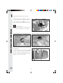
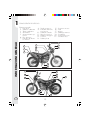
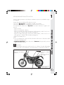
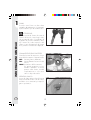
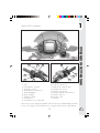
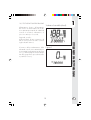

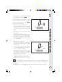
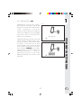
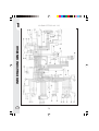
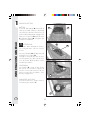
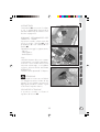
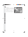

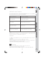
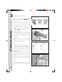
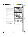
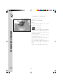
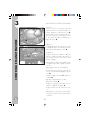

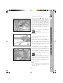
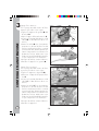
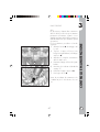
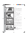
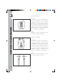

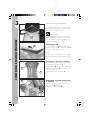
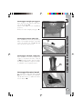
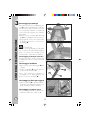
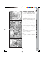
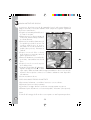

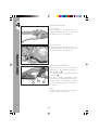

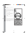

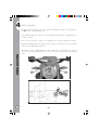

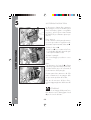
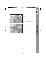
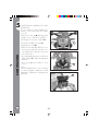
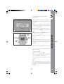

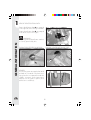
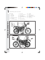
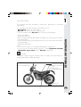
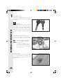
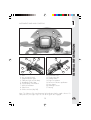

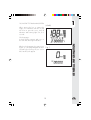
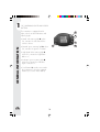
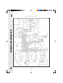
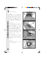
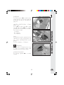

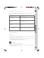
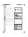
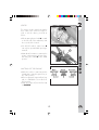
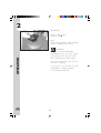
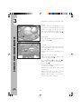
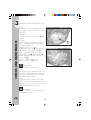
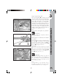
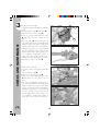
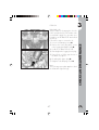
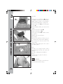
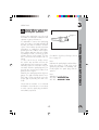
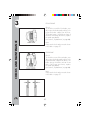
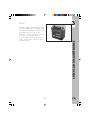
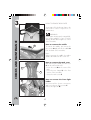
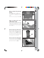
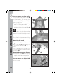
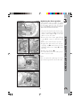
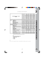
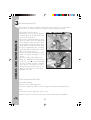
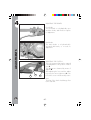
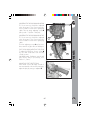


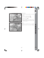
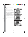
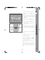


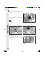
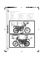
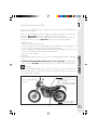
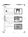
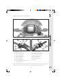
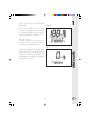
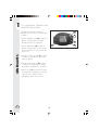
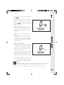
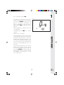
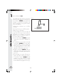
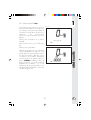
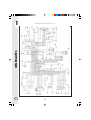
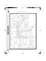
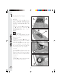
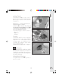
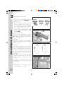
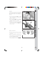
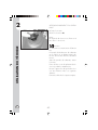
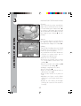
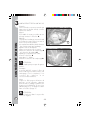
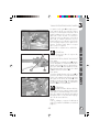
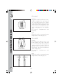
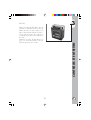
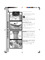
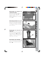
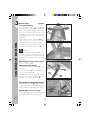
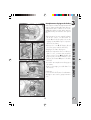
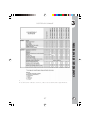
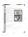
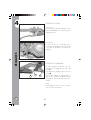
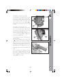
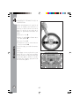
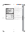
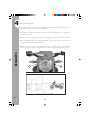
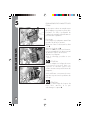
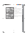
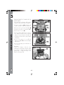


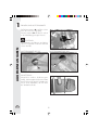
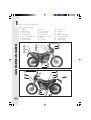
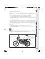
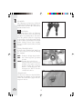
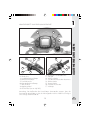
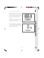
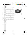
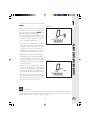
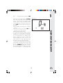
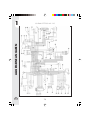
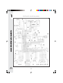


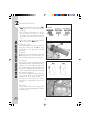
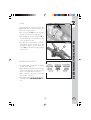
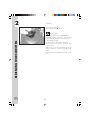
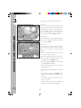
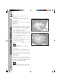
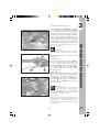
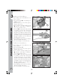
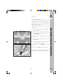
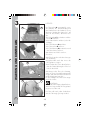
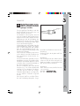
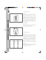
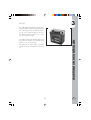
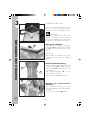


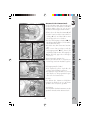

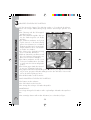

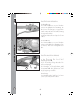
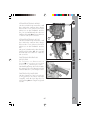
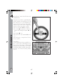
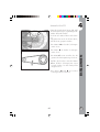
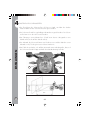
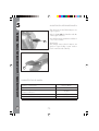

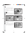
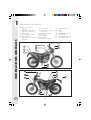
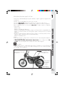
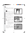
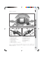

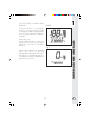
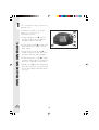
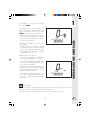
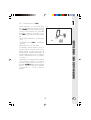
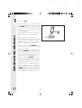
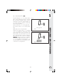
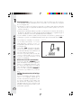
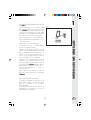


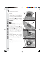
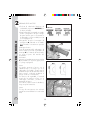
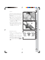
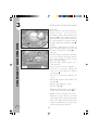
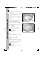
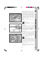

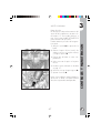
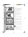
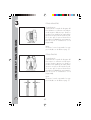
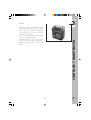
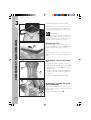
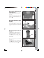
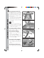
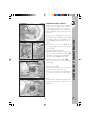
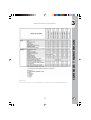
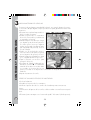
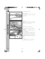
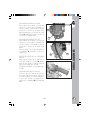


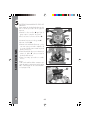
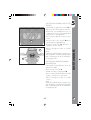


![Bedienungsanleitung [de]](http://vs1.manualzilla.com/store/data/006742948_1-d69552d9601790905b82c309e5f3def5-150x150.png)