1
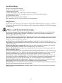
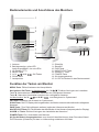
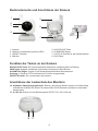
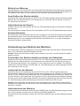
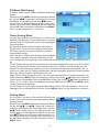
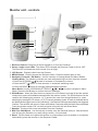
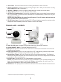
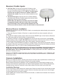
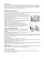
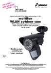
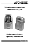
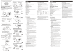
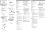
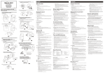
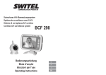
multifon digi digitales Funk-Überwachungssystem digital wireless monitoring system Art.-Nr. 51055 Bedienungsanleitung User manual Farbe Nachtsicht color night vision Wichtig Lesen Sie vor Inbetriebnahme des Geräts alle Bedienhinweise aufmerksam und vollständig durch. Bewahren Sie diese Anleitung sorgfältig auf, sie enthält wichtige Betriebshinweise. Important Please read this booklet carefully to make yourself familiar with the various functions of your stabo multifon digi. Lieferumfang: Kamera mit integriertem Sender Monitor mit integriertem Empfänger Ladeschale für Monitor Li-Ionen-Akkupack (7,4 V / 950 mAh, im Monitor montiert) 2 Steckernetzteile (9 V DC / 600 mA für Kamera, 9 V DC/1200 mA für Monitor) AV (Audio/Video)-Kabel Bedienungsanleitung (deutsch/englisch) Bitte überprüfen Sie den Packungsinhalt auf Vollständigkeit. Allgemein Prüfen Sie vor der Benutzung der Geräte, ob äußerliche Beschädigungen vorliegen. In diesem Fall nehmen Sie das Produkt nicht in Betrieb, sondern setzen sich umgehend mit Ihrem Fachhändler in Verbindung. Warn- und Sicherheits-Hinweise Nur für die Nutzung in geschlossenen Räumen! Ihr stabo Multifon digi ist ausschließlich für den Betrieb in geschlossenen Räumen vorgesehen, setzen Sie die Geräte keinesfalls den Witterungseinflüssen im Freien aus. Feuchte und/oder staubige Räume meiden! Betreiben Sie Ihr stabo Multifon digi nicht in feuchten oder besonders staubigen Räumen (z. B. Badezimmer, Tischlerei). Die empfindlichen elektronischen Geräte könnten sonst Schaden nehmen. Vor Vibrationen und Erschütterungen schützen! Stellen Sie Ihr stabo Multifon digi nur auf kippsicheren, ebenen Unterlagen auf. Schützen Sie die Geräte vor Stürzen, Erschütterungen und starken Vibrationen. Niemals bei Gewitter benutzen! Benutzen Sie die Geräte niemals bei Gewitter! Trennen Sie sie bei heranziehendem Gewitter bzw. bei Abwesenheit vom Stromnetz! Nicht in Kinderhände! Verhindern Sie, dass Kinder mit den Geräten, Zubehörteilen oder Verpackungsmaterial spielen. Nicht im Krankenhaus oder vergleichbaren Einrichtungen benutzen! Ihr stabo Multifon digi erzeugt Funkwellen, die u. U. Geräte im Krankenhaus beeinträchtigen können. Klären Sie ggf. mit dem verantwortlichen Personal, ob Sie Ihr stabo Multifon digi dort nutzen können. Nicht öffnen keine Veränderungen vornehmen! Öffnen Sie niemals Ihr stabo Multifon digi und nehmen Sie keine Veränderungen vor - sonst entfallen Garantie und möglicherweise auch die Gerätezulassung! Lassen Sie das Gerät nur von fachkundigen Personen reparieren. Bei beschädigtem Gehäuse Netzstecker ziehen! Ist das Gehäuse Ihres stabo Multifon digi beschädigt, trennen Sie das Gerät sofort vom Stromnetz (bei Netzteil-Betrieb). Beachten Sie, dass die Überwachung per Funkgerät zwar die Betreuung eines Kindes erleichtern, jedoch nie die persönliche Aufsicht ersetzen kann! Werfen Sie Akkupacks/Batterien nie ins Feuer! Schließen Sie die Kontakte des Akkupacks niemals kurz! 2 Bedienelemente und Anschlüsse des Monitors 1 2 10 3 4 5 6 11 12 7 8 13 14 15 9 1. Antenne 2. Betriebsanzeige: grüne LED Audio-Signalstärke: vier rote LEDs 3. LC-Display (TFT) 4. MENU-Taste A/M OK-Tasten 5. V+/V6. SCAN-Taste 7. Lautsprecher 8. 9. 10. 11. 12. 13. 14. 15. Gürtelclip Standfuß PAIR-Taste NACHTLICHT-Taste ALARM +/- Taste POWER-Taste AV-Ausgangsbuchse 9 V DC IN: Buchse für das Steckernetzteil Funktion der Tasten am Monitor MENU-Taste: Öffnen/Verlassen des Haupt-Menüs Erhöhen/Verringern der Lautstärke Navigations-/OK-Taste: Im Arbeitsmodus: V+ / V-/ Taste A: Automatisches Umschalten zwischen den verfügbaren Kameras Taste M: Manuelles Umschalten zwischen den verfügbaren Kameras Im Menümodus: V+/V- / und A/ M / zum Navigieren im Systemmenü OK-Taste: Bestätigen der Auswahl im Systemmenü SCAN-Taste: Das LC-Display wird ausgeschaltet, der Monitor scannt kontinuierlich alle verfügbaren Kameras PAIR-Taste: Zum Pairing/Koppeln weiterer (optionaler) Kameras am Monitor NACHTLICHT-Taste: Ein-/Ausschalten des Nachtlichts an der Kamera (Lampensymbol im Display) ALARM +/- Taste: Erhöhen/Verringern der Lautstärke des Alarmtons POWER-Taste: Ein-/ Ausschalten des Monitors AV (Audio/Video)-Ausgangsbuchse: zum Anschluß des Monitors an einen Fernseher/Video-/ DVD-Recorder (Aufnahme) mit dem im Lieferumfang enthaltenen AV-Kabel 3 Bedienelemente und Anschlüsse der Kamera 1 5 2 3 6 4 7 1. 2. 3. 4. 8 Antenne Objektiv und Abdeckung Infrarot LEDs ON/OFF-Schalter Mikrofon 5. 6. 7. 8. NACHTLICHT-Taste ALARMTON-Regler 9 V DC IN: Buchse für das Steckernetzteil PAIR-Taste Funktion der Tasten an der Kamera NACHTLICHT-Taste: Ein-/Ausschalten des Nachtlichts (Lampensymbol im Display) PAIR-Taste: Koppeln zusätzlicher (optionaler) Kamera/s mit dem Monitor ALARMTON- Regler: Regler für die Ansprechempfindlichkeit des Alarmtons Achtung: In Position OFF ist die Alarmton-Funktion ausgeschaltet ON/OFF-Schalter: Ein-/ Ausschalten der Kamera Anschlüsse der Ladeschale des Monitors 16. AV(Audio/ Video)-Ausgangsbuchse: Buchse, über die der Monitor mit dem im Lieferumfang enthaltenen AV-Kabel mit einem Fernseher/Video-/DVD-Recorder (Aufnahme) verbunden werden kann 17. 9 V DC IN: Buchse für das Steckernetzteil OUTPUT 9 V DC/ 1200 mA 16 17 4 Installation der Kamera Die Kamera wird über das 9 V-Steckernetzteil, mit Batterien (4 x AA Alkalinebatterien, nicht im Lieferumfang enthalten) oder einen optional erhältlichen Akkupack betrieben. Hinweis: Sie können bis zu 4 Kameras (Zusatzkameras optional erhältlich) an einem Monitor betreiben. Die zusätzlichen Kameras müssen dazu mit dem Monitor gekoppelt werden (siehe Abschnitt Pairing/Koppeln). Hinweise zum Aufstellen und Befestigen der Kamera: Stellen Sie die Kamera auf eine kippsichere, ebene Unterlage. Die Kamera darf weder Feuchtigkeit/ Nässe noch übermäßigem Staub oder starken Vibrationen ausgesetzt sein. Richten Sie das Objektiv auf den Überwachungsbereich und stellen Sie durch Drehen des Objektivkopfes den optimalen Winkel ein. Vermeiden direkte Sonneneinstrahlung oder starke Lichtquellen. Wandmontage der Kamera Die Kamera ist auch für eine Befestigung an der Wand geeignet. Verwenden Sie zwei für die Beschaffenheit des Untergrunds geeignete Schrauben. Achten Sie bei der Wahl der Schrauben auch darauf, dass die Schraubenköpfe durch die Vorbohrungen (A) im Kamerafuß passen! Achtung: Befestigen Sie die Kamera am geplanten Montageort zunächst provisorisch und überprüfen Sie Ausrichtung, Blickwinkel und Übertragungsqualität. Optimieren Sie bei Bedarf die Position und bohren erst dann die zwei Löcher für die Befestigungsschrauben. Befestigen Sie die beiden Schrauben, setzen Sie den Kamerafuß auf die Schrauben und ziehen Sie die Kamera leicht nach unten, um sie zu sichern. Richten Sie abschließend das Objektiv auf den Überwachungsbereich und stellen Sie durch Drehen des Objektivkopfes den optimalen Winkel ein. A Einlegen von Batterien Öffnen Sie die Abdeckung des Batteriefachs an der Unterseite der Kamera. Legen Sie 4 Alkalinebatterien (AA) ein - beachten Sie dabei die Plus-/Minus-Zeichen im Batteriefach! Schließen Sie die Abdeckung wieder. Hinweis: Mischen Sie niemals alte und neue Batterien oder Zellen verschiedenen Typs! Entfernen Sie die Batterien aus der Kamera, wenn Sie diese längere Zeit nicht nutzen. Akkupack (optionales Zubehör) laden Öffnen Sie die Abdeckung des Batteriefachs an der Unterseite der Kamera. Legen Sie den als optionales Zubehör erhältlichen Akkupack ein. Schließen Sie die Abdeckung wieder. Stecken Sie das mit OUTPUT 9 V DC / 600 mA gekennzeichnete Steckernetzteil in eine Steckdose und verbinden Sie den Stecker mit der 9 V DC IN-Buchse der Kamera. Die seitliche Ladekontroll-LED am Kamerafuß leuchtet rot. Nach Beendigung des Ladevorganges schaltet die Ladekontroll-LED auf grün. 5 Batterie leer-Warnung Sind die Batterien verbraucht oder ist die Kapazität des Akkupacks erschöpft beginnt die grüne LED (Betriebsanzeige) zu blinken. Nach einer Weile schaltet sich die Kamera ab. Ersetzen Sie die Batterien bzw. laden Sie den Akkupack oder schließen das Steckernetzteil an. Anschließen des Steckernetzteils Verwenden Sie für die Kamera das mit OUTPUT 9 V DC/ 600 mA gekennzeichnete Steckernetzteil. Stecken Sie das Steckernetzteil in eine Steckdose und verbinden Sie den Stecker mit der 9 V DC IN-Buchse der Kamera. Inbetriebnahme der Kamera Schieben Sie den Ein-/Ausschalter auf ON, die LED (Betriebsanzeige) unterhalb des Schalters leuchtet grün. Zum Ausschalten schieben Sie den Ein-/Ausschalter auf OFF, die LED (Betriebsanzeige) erlischt. Nachtsichtfunktion Bei schlechten Lichtverhältnissen aktiviert der Lichtsensor in der Gehäuserückwand automatisch die Nachtsichtfunktion. Acht Hochleistungs-Infrarot-LEDs an der Kamera ermöglichen dabei eine Bildübertragung auch aus abgedunkelten Räumen (Sichtweite bis ca. 3 m), das empfangene Monitorbild ist dann schwarz/weiß. Vorbereitung zum Betrieb des Monitors Der Monitor kann über den integrierten Li-Ionen Akkupack mobil oder über das 9 V-Steckernetzteil bzw. in der Ladeschale stationär betrieben werden. Hinweis: Wenn Sie den Monitor mobil nutzen möchten muss der Li-Ionen Akkupack zunächst geladen werden! Anschließen des Steckernetzteils und Laden des Akkupacks Verwenden Sie für den Monitor das mit OUTPUT 9 V DC/1200 mA gekennzeichnete Steckernetzteil. Stecken Sie das Steckernetzteil in eine Steckdose und verbinden Sie den Stecker mit der 9 V DC IN-Buchse des Monitors: der integrierte Li-Ionen Akkupack wird nun geladen. Die seitliche Ladekontroll- LED am Monitor leuchtet dabei rot, nach Beendigung des Ladevorganges schaltet die Ladekontroll-LED auf grün. Ladeschale für den Monitor Verwenden Sie für die Ladeschale das mit OUTPUT 9 V DC/ 1200 mA gekennzeichnete Steckernetzteil. Stecken Sie das Steckernetzteil in eine Steckdose und verbinden Sie den Stecker mit der 9 V DC IN-Buchse der Ladeschale, die LED (Betriebsanzeige) leuchtet grün. Stellen Sie nun den Monitor in die Ladeschale: der integrierte Li-Ionen Akkupack wird automatisch geladen, Sie können den Monitor gleichzeitig betreiben. Die seitliche Ladekontroll-LED am Monitor leuchtet rot. Nach Beendigung des Ladevorgangs schaltet die Ladekontroll-LED auf grün. Hinweis: Die Ladeschale verfügt über eine AV-Ausgangsbuchse. Über das im Lieferumfang enthaltene AV-Kabel lässt sich der Monitor über die Ladeschale mit einem Fernseher/Video-/DVDRecorder verbinden. Inbetriebnahme des Monitors Um den Monitor einzuschalten drücken Sie die POWER Taste. Die LED (Betriebsanzeige) leuchtet grün und im Display erscheint kurz der Schriftzug DIGITAL MONITOR. Um den Monitor auszuschalten drücken Sie erneut die POWER Taste. Die LED (Betriebsanzeige) erlischt. 6 Automatische Herstellung der Verbindung zwischen Monitor und Kamera Die Funkverbindung zwischen Kamera und Monitor wird automatisch hergestellt, sobald beide Geräte eingeschaltet sind und sich innerhalb des Reichweitenradius befinden: das Display des Monitors zeigt dann das aufgenommene Bild der Kamera. Hinweis: Optionale Zusatzkameras müssen zuerst mit dem Monitor gekoppelt werden (siehe Pairing-Menü/Koppeln). Anzeige im LC-Display Die Stärke des Empfangssignals der Kamera wird im Monitor als Balkendiagramm dargestellt. Signalstärke Anzeige Warnung Optimal - Gut - Annehmbar Schwaches Signal Schlecht Sehr schwaches Signal Kein Signal Kein Signal Schwaches-/Kein Signal-Warnung: Wenn der Abstand zwischen Kamera und Monitor zu groß wird erscheint im Display eine Warnmeldung: LOW SIGNAL: das Kamerabild wird noch übertragen, die Signalstärke beträgt jedoch nur noch ein oder zwei Balken, die Reichweitengrenze ist erreicht. NO SIGNAL: Die Reichweitengrenze ist überschritten (oder die Kamera ausgeschaltet), eine Bildübertragung ist nicht mehr möglich. Verringern Sie den Abstand zwischen Kamera und Monitor (bzw. schalten Sie die Kamera ein). Kanal-Anzeige Das Display zeigt die aktuelle Kamera-Nummer (Cam1) an. Beim Einsatz mehrerer Kameras können Sie durch Drücken der M-Taste zwischen den verfügbaren Kameras umschalten, für einen automatischen Wechsel drücken Sie die A-Taste (AUTO). Lautstärke einstellen Durch Drücken der Tasten V+ (lauter) oder V- (leiser) lässt sich die Lautstärke in 5 Stufen ändern. Die eingestellte Lautstärke wird als Balkendiagramm im Display angezeigt. Nach 10 Sek. erlischt die Anzeige. Alarmton-Funktion Um das LC-Display nicht ständig im Blick behalten zu müssen können Sie sich über die AlarmtonFunktion Geräusche im Überwachungsbereich am Monitor akustisch melden lassen. Wenn diese Funktion aktiviert ist und ein Geräusch vom Mikrofon der Kamera aufgenommen wird, welches über der eingestellten Ansprechempfindlichkeit liegt, so ertönt ein sich mehrmals wiederholender Alarmton. Die Ansprechempfindlichkeit des Mikrofons ist über einen an der Seite der Kamera befindlichen Regler (s.S. 4 (6)) einstellbar. AV-Anschlußbuchse Über das im Lieferumfang enthaltene AV-Kabel wird der Monitor über die Ladeschale mit einem Fernseher oder einem Video-/DVD-Recorder (für Aufnahme) verbunden. Stecken Sie dazu den 3,5 mm Klinkenstecker in die AV-Buchse der Ladeschale und die Cinchstecker in die dafür vorgesehenen Buchsen von Fernseher bzw. Videorekorder. Das LC-Display des Monitors wird während der Verbindung abgeschaltet. Wird die Verbindung unterbrochen (Entfernen des 3,5 mm Klinkensteckers aus der Ausgangsbuchse) wird das LC-Display wieder eingeschaltet. Achtung: Die AV-Funktion wird nur aktiviert, wenn das Steckernetzteil angeschlossen ist! 7 Scan-Funktion Beim Einsatz mehrerer Kameras prüft der Monitor dabei im regelmäßigen Wechsel, ob auf einem der Kanäle (bei einer der Kameras) ein Signal anliegt. Achtung: Aktivieren Sie zuerst bei allen Kameras die Alarmton-Funktion! Durch Druck auf die SCAN Taste aktivieren Sie die Scan-Funktion: das LC-Display wird ausgeschaltet und der Monitor scannt kontinuierlich alle verfügbaren Kameras. Empfängt eine der Kameras ein Geräusch, welches über der eingestellten Alarmton-Empfindlichkeit liegt, wird der Monitor aktiviert und das Bild dieser Kamera für ca. 8 Sek. angezeigt. Danach wird das LC-Display wieder ausgeschaltet und der Scan-Vorgang wird fortgesetzt. Zum Ausschalten der Scan-Funktion drücken Sie eine beliebige Taste (außer der OK Taste). Haupt-Menü Zum Aufrufen des Hauptmenüs drücken Sie die MENU Taste. Mit den s/t Tasten können Sie die einzelnen Untermenüs anwählen. Es stehen vier Untermenüs zur Verfügung: PAIRING: Koppeln einer Zusatzkamera an den Monitor EV: Einstellen des Belichtungslevels der Kamera POWER SAVING: Schaltet den Monitor auf Energiesparmodus-Modus SETTING: Einstellen der AV-Ausgang-Optionen und Zurücksetzen des Monitors auf Werkseinstellung Pairing-Menü (Koppeln) Wenn Sie mehrere Kameras an einem Monitor betreiben wollen müssen Sie die Zusatzkamera/s mit dem Monitor koppeln. Schalten Sie dazu Kamera und Monitor ein. Weisen Sie der zusätzlichen Kamera zunächst einen Kanal zu: öffnen Sie mit der MENU-Taste das Hauptmenü, wählen mit den -Tasten das Untermenü PAIRING aus und bestätigen Sie mit der OK-Taste. -Tasten den Kanal aus, Wählen Sie nun mit den den Sie dieser Kamera zuweisen wollen, und bestätigen mit der OK-Taste. Drücken Sie nun mit der Spitze eines Stifts oder mit einer Büroklammer die PAIR-Taste (10) des Monitors (auf der Unterseite). Im Display erscheint die Aufforderung, innerhalb der nächsten 30 Sek. die PAIR-Taste (8) der Kamera (auf der Rückseite unterhalb der Halterung) zu drücken. Mit dem Drücken der PAIR-Taste an der Kamera erfolgt die automatische Koppelung und das Kamerabild erscheint im Monitor. Sollten Sie die PAIR-Taste der Kamera nicht innerhalb von 30 Sek. gedrückt haben, wird der Monitor in den Normalmodus zurückgesetzt, die Koppelung der Zusatzkamera erfolgt nicht. Hinweis: Weitere Kameras (bis insgesamt 4) koppeln Sie ebenfalls entsprechend dieser Schritte. 8 EV-Menü (Belichtung) In diesem Menü können Sie die Lichtstärke der Kamera ändern. Öffnen Sie mit der MENU-Taste das Hauptmenü, wählen -Tasten das Untermenü EV aus und Sie mit den bestätigen mit der OK-Taste. Mit den -Tasten können Sie nun die Belichtung verändern (nach links dunkler, nach rechts heller). Bestätigen Sie Ihre Änderung mit der OK-Taste und drücken anschließend die MENUTaste, um das Hauptmenü zu verlassen. Power Saving Menü Um den Stromverbrauch des Monitors zu senken und damit die Standzeit des Li-Ionen Akkupacks zu erhöhen lässt sich das LC-Display nach einer zuvor festgelegten Zeit ausschalten. Bei aktivierter Power Saving-Funktion kann das LCDisplay durch Druck auf eine beliebige Taste (außer OK-Taste) oder durch Geräuschaktivierung wieder eingeschaltet werden. Wenn Sie das LC-Display durch Drücken einer beliebigen Taste wieder aktivieren wird das Kamerabild für die zuvor festgelegte Zeit angezeigt, dann schaltet die Power Saving-Funktion das Display erneut ab. Für die Display-Aktivierung durch Geräusche im Überwachungsbereich muss zuvor die Funktion Alarmton eingeschaltet werden (siehe Abschnitt Alarmton-Funktion). Nimmt das Mikrofon der Kamera ein entsprechendes Geräusch (je nach eingestellter Ansprechempfindlichkeit) auf, so wird für ca. 8 Sek. das LC-Display eingeschaltet und das Kamerabild angezeigt. Danach schaltet die Power Saving-Funktion das Display erneut ab. Legen Sie im Power Saving-Menü fest, nach wie vielen Minuten das LC-Display abschalten soll: -Tasten das Untermenü Öffnen Sie mit der MENU-Taste das Hauptmenü, wählen Sie mit den Power Saving und bestätigen Sie mit der OK-Taste. Wählen Sie mit den -Tasten die AbschaltZeit (1, 2, 5 o. 10 Min.) aus und bestätigen Sie mit der OK-Taste. Drücken Sie die MENU-Taste, um das Hauptmenü verlassen. Um die Power Saving-Funktion auszuschalten wählen Sie im Power Saving-Menü Cancel und bestätigen Sie mit der OK-Taste. Drücken Sie die MENU-Taste, um das Hauptmenü verlassen. Setting Menü A/V Out Menü: hier können Sie die Bild-Auflösung des auf den Fernseher/Videorecorder übertragenen Kamerabildes ändern. Öffnen Sie mit der MENU-Taste das Hauptmenü, wählen - und -Tasten das Untermenü Sie mit den Setting und bestätigen Sie mit der OK-Taste. Mit den -Tasten wählen Sie nun den Menüpunkt A/V Out und bestätigen mit der OK-Taste. Wählen Sie dann mit den -Tasten High für hohe Auflösung oder Low für niedrige Auflösung. Bestätigen Sie Ihre Eingabe mit der OK-Taste. Verlassen Sie das Hauptmenü mit der MENU-Taste. 9 Mit Default können Sie den Monitor auf Werkseinstellung zurückzusetzen. Hinweis: Die Kameras bleiben dabei mit dem Monitor gekoppelt. - und -Tasten Öffnen Sie mit der MENU-Taste das Hauptmenü, wählen Sie mit den das Untermenü Setting und bestätigen Sie mit der OK-Taste. Mit den -Tasten wählen Sie Default. Bestätigen Sie mit der OK-Taste. Wählen Sie mit den -Tasten Yes aus und bestätigen Sie mit der OK-Taste. Verlassen Sie das Hauptmenü mit der MENU-Taste. Pflegehinweise Schützen Sie die Geräte vor Hitze (z.B. direkte Sonneneinstrahlung), Feuchtigkeit, Staub und starken Erschütterungen. Reinigen Sie die Geräte nur mit einem trockenen, weichen, fusselfreien Tuch. Verwenden Sie keine aggressiven Reinigungsmittel. Halten Sie die Batteriekontakte sauber. Entnehmen Sie die Batterien, wenn Sie die Geräte längere Zeit nicht nutzen werden. Entsorgungshinweise Elektrische/elektronische Geräte und Batterien gehören nicht in den Hausmüll! Bitte geben Sie gebrauchte/defekte Geräte sowie verbrauchte Batterien (nur völlig entleert) bei den entsprechenden Sammelstellen (z. B. Ihres kommunalen Entsorgers) ab! Fehlersuche Problem Überprüfung/Abhilfe Kein Bild Sind Monitor und Kamera eingeschaltet und leuchten beide LEDs (Betriebsanzeigen) grün? Sind die Stecker der Steckernetzteile korrekt eingesteckt? Bei Mobilbetrieb: Sind die Batterien korrekt in die Kamera eingelegt (Polung)? Ist der Li-Ionen Akkupack des Monitors geladen? Verringern Sie gegebenenfalls den Abstand zwischen Kamera und Monitor. Das Bild ist rückläufig Verringern Sie den Abstand zwischen Kamera und Monitor. Optimieren Sie die Ausrichtung von Kamera und Monitor. Zu leises oder kein Audiosignal Positionieren Sie das Mikrofon der Kamera näher an der Geräuschquelle. Rückkopplung Kamera und Monitor stehen zu dicht aneinander: vergrößern Sie den Abstand. Das Bild ist kabbelig Die Geräte arbeiten mit einer geringeren Frame-Rate. Verringern Sie den Abstand zwischen Kamera und Monitor. Entfernen Sie ggf. Hindernisse zwischen Kamera und Monitor. Das Bild ist (bei Verwendung des AV- Ausgangs) auf einem großen Fernseher grobkörnig Die Auflösung der Kamera ist VGA (680x480). Nutzen Sie (falls vorhanden) die Funktion BiB (Bild im Bild) Ihres Fernsehers oder verwenden Sie einen kleineren Bildschirm. 10 Technische Daten Monitor Frequenz Daten Rate Empfindlichkeit Demodulation Type Bildauflösung Betrachtungs-Winkel AV Ausgangs-Bildauflösung Alarm Empfindlichkeit Betriebsspannung Stromaufnahme Maße (B x H x T) Gewicht Kamera Frequenz Daten Rate Modulation Type Maximale Reichweite Bildsensor Effektive Bildpunkte Bildauflösung/ Einzelbild-Rate AES automatischer Weißabgleich Objektiv Betrachtungs-Winkel (Diagonal) Min. Lichtstärke IR LED Betriebsspannung Stromaufnahme Maße (B x H x T) Gewicht 2.400 ~ 2.482 GHz 1.5 Mbps - 81 dBm GFSK mit FHSS H: 480 V: 240 H: 50° V: 50° VGA 640x480 15FPS, QVGA 320x240 30FPS 80 dB +/- 10% (1M) 9 V DC +/- 5% 400 mA ohne Laden, 800 mA mit Laden 75 x 145 x 30 mm 180 g (incl. LiIon-Akku) 2.400 ~ 2.482 GHz 1.5 Mbps GFSK mit FHSS 150 m bei freier Sicht ¼ CMOS Farbe H:640 V:480 H:640 V:480 / 30FPS max. ON1/2000 !/20 sec. JA 4.9 mm / F2.8 60° 2.5 LUX (IR OFF), 0 LUX (IR ON) 8 LEDs 9 V DC +/- 5% 360 mA mit Nachtlicht, 300 mA ohne Nachtlicht 80 x 110 x 60 mm 140 g 11 Package Content Please note that the package should include the following: Camera with integrated Transmitter Monitor with integrated Receiver Li Ionen battery pack (7,4 V / 950 mAh), mounted at monitor Power Adaptor for Camera (9 V DC/ 0,6 A) Power Adaptor for Monitor (9 V DC/ 1,2 A) Charging cradle for receiver AV (Audio/Video)-Cable User Manual If you find any of the above missing, please contact your retailer. Safety Instructions Please observe the following precautions to prevent fire, personal injury and product damage: Read Instructions: All the safety and operating instructions should be read before the 2.4GHz Color LCD A/V Wireless Monitor is operated. Retain Instructions: The safety and operating instructions should be retained for future reference. Heed Warnings: All warnings on the 2.4GHz Color LCD A/V Wireless Monitor and operating instructions should be adhered to. Follow Instructions: All operating instructions should be followed. Water and Moisture: This product is designed for the indoor use only. The unit should not be exposed to dripping or splashing and that no objects filled with liquids, such as vases, shall be placed on the unit. The item should not be used near water; for example, near a bath tub, wash bowl, kitchen sink, laundry tub in a wet basement, of near a swimming pool, etc. Ventilation: The 2.4GHz Color LCD A/V Wireless Monitor should not be situated on a bed, sofa, rug, or similar surface that may block the ventilation openings, or placed in an enclosed installation, such as a bookcase or cabinet that may impede the flow of air through the ventilation openings. Heat: The 2.4GHz Color LCD A/V Monitor should be situated away from heat sources such as radiators, heat registers, stoves, or other appliances that produce heat. No naked flames sources, such as lighted candles, should be placed on the apparatus. Power Source: Besides batteries operated, the 2.4 GHz Color LCD A/V Monitor should be connected to a power supply only of the type described in this operating instruction (AC/DC adaptors: 9V 500 mA Centre Positive). Cleaning: Use a dry cotton cloth to keep the 2.4 GHz Color LCD A/V monitor free of dust. Do not use water! Non-Use Periods: Always remove the batteries from the camera and the monitor battery packs or unplug the AC adaptors from wall outlets during long periods of non-use. 12 Object and Liquid Entry: Care should be taken so that objects do not fall into, and liquids are not spilled into the enclosure through the openings. Damage Requiring Services: The 2.4 GHz Color LCD A/V monitor should be serviced by qualified service personnel when: a. Objects have fallen or liquid has been spilled into the products; or b. The units have been exposed to rain; or c. The units do not appear to operate normally or exhibits a marked change in its performance; or d. The units have been dropped or the enclosure damaged. Caution: a. This product cannot replace responsible adult supervision of a child. You should personally check your childs activity at regular intervals. b. Never use this 2.4 GHz Color LCD A/V Wireless Monitor to a degree where your life or health or the life or health of others or integrity of property depends on its function! Manufacturer will not accept any responsibility or claim for death and injury of any person or lost and damage of any property due to malfunction or misuse of the product. Battery: a. Remove the batteries from the appliance when it is not used for long period and prior to disposal of the appliance. b. Keep batteries out of reach of children, do not throw them into fire, short circuit them or dismantle them. c. Immediately see a doctor if a battery is swallowed. d. If required, clean battery and appliance contacts prior to inserting batteries. e. Never attempt to recharge non-rechargeable batteries. Risk of explosion! f. Do not expose batteries to extreme conditions, e.g. on radiators. Increased risk of leakage! g. Immediately remove discharged batteries from the appliance. Increased risk of leakage! h. If not observed, batteries could be discharged beyond their end voltage and leak. Immediately remove leaking batteries from the appliance. Caution: Risk of corrosion due to leaking battery liquid! i. Avoid contact with skin, eyes and mucous membranes. In the event of contact with battery acid, immediately rinse the affected areas with plenty of clear water and immediately see a doctor. Statement On Regulation These limits are designed to provide reasonable protection against harmful interference in a residential installation. This equipment generate, uses and can radiate radio frequency energy and if not installed and used in accordance with the instructions, may cause harmful interference to radio communications. However, there is no guarantee that interference will not occur in a particular installation. If this equipment does cause harmful interference to radio or television reception, which can be determined by turning the equipment off and on, the user is encouraged to try to correct the interference by one or more of the following measures: l Reorient or relocate the receiving antenna. l Increase the separation between the equipment and receiver. l Connect the equipment into an outlet on a circuit different from that to which the receiver is connected. l Consult the dealer or an experienced radio/TV technician for help. Operation with non-approved equipment or unshielded cables is likely to result in interference to radio or TV reception. The user is cautioned that changes and modifications made to the equipment without the approval of manufacturer could void the users authority to operate this equipment. 13 Monitor unit - controls 1 2 10 3 4 5 6 11 12 7 8 13 14 15 9 1. Receiver Antenna Receives & Sends signals to or from the Cameras* 2. Power / Audio Level LEDs The Green LED indicates the Receiver Power is ON or OFF. The Red LEDs indicate the Audio Levels (Low to High). 3. LCD Screen Displays video from the Camera. 4. MENU Button Press to Access the Receiver Menu. Press the button again to exit. 5. Navigation Controls / OK Button Use the controls in Viewing Mode and Menu Modes: Viewing Mode: The following controls are used while watching live video from the camera: arrows to Increase or Decrease the volume. o Press the UP/DOWN o Press the LEFT arrow to view cameras* in automatic switching mode. o Press the RIGHT arrow to manually switch between cameras*. / arrows to navigate in Menu Menu Mode: Use the UP/DOWN/LEFT/RIGHT Mode. Press the OK Button to confirm the menu selection. 6. SCAN Button When the Scan button is pressed, the LCD Screen is turned off and the system continuously scans all available cameras while the monitor is dark. The SCAN feature can be used for the following two reasons: (1) To prevent the user from being disturbed (i.e. when sleeping) by the bright LCD screen, or (2) To conserve battery power. If audio is detected above the preset audio trigger level on the Camera(s)*, the Receiver will beep and display the triggered Camera. The receiver will return to Scan mode about 5 seconds after the Alarm has completed. Press any button except OK on the front panel of monitor will exit Scan Mode. 7. Speaker Produces the sound transmitted from the Cameras*. 8. Belt Clip / Wall Mount Use the belt clip to easily carry the Receiver with you. Use the Mount hole to hang the Receiver on a wall (using a screw not included). 9. Stand Flip the stand out to place the receiver on a flat surface (such as a table or countertop). Alternatively, place the receiver in the Receiver Cradle. 14 10. Pair Button Press the Pair button when Pairing the Receiver with a Camera. 11. Night Light Button Press to remotely turn Night Light ON or OFF (for the camera currently being displayed on the LCD Screen). 12. A Alarm +/-Button Press to increase or decrease the volume of the audio alarm. 13. Power Button Press to turn the Receiver ON or OFF. 14. A/V Out Port (Optional Use) Connect the included A/V Cable to view video from the receiver on a TV or Monitor, or record to a DVD Recorder or VCR. Alternatively, use the A/V Out port on the Receiver Cradle. NOTE: Using this feature will turn off the LCD screen. The LCD screen will turn back on when the A/V Cable is disconnected. 15. DC 9V Power Input Connect the included DC 9V Power Adaptor to power the receiver and/or charge the Receiver battery (when the receiver is not in the Cradle). Camera unit - controls 1 2 3 5 6 4 7 8 1. Camera Antenna Receives & Sends signals to or from the Receiver 2. Lens / IR LED Cover Infrared LEDs provide viewing in no/low light conditions. 8. Camera ON/OFF Switch Turns the Camera ON or OFF. 4. Microphone Receives sounds for the area near the camera, and transmits sound from the Camera to the Receiver. 5. Night Light Switch Press to turn the Light ON or OFF. Alternatively, press the Light button on the Receiver to remotely turn the Camera Light ON or OFF. 6. Sound Alarm Trigger Adjust the Trigger to set the Sound Alarm sensitivity. The Receiver will beep to alert the user when the sound is above a preset sound level. Adjust the side wheel to Increase or Decrease the level. 7. DC 9V Power Connect the DC 9V Power Adaptor to the Camera. NOTE: The Camera can also be powered using 4 AA Batteries (not included) installed in the base. If the Camera is plugged in with the AC Adaptor, the batteries will not be used. The batteries are intended for short term, portable Camera use. 8. PAIR Button The pairing button is located on the back of the camera behind the stand mount. * Additional cameras available as optional accessory. 15 Receiver Cradle Inputs 16. A/V Out Port Connect the included A/V Cable to view the receiver picture (when docked) on a TV or Monitor, or record to a DVD Recorder or VCR. (NOTE: The A/V output function will not work if there is no power cable connected to the cradle. Only one A/V out port should be used at a time). 17. DC 9V Power Input Connect the DC 9V Power Adaptor (included) to the Receiver Cradle to power the receiver and/or charge the Receiver (when docked). NOTE: When the Receiver is docked, and the A/V Cable 16 17 is connected (power cable as needs to be connected), the LCD Screen on the receiver will be blacked out. The LCD screen will turn back on when the A/V Cable is disconnected. Wireless Receiver Installation Determine if you will be using the Receiver Cradle, or connecting the cables directly to the receiver before installation: 1. Place the Receiver Cradle or Receiver in a place that will have clear reception with your camera(s). 2. Plug the AC adaptor power output cable into the 9V POWER input of the Cradle or Receiver Plug the power plug into a wall outlet or surge protector. 3. Leave the receiver to charge for 6 hours prior to first time use so the built-in rechargeable receiver battery is fully charged. DO NOT remove the power cable from the receiver / from the cradle during initial charging process. After initial charge, charge as required. 4. If you wish to view the Receiver images on a larger screen, connect the included AV Cable to the Cradle or Receiver, and connect the other end of the Cable to the Video IN (Yellow) and Audio IN (White) ports on the TV, VCR or other viewing/recording device. NOTE: the purpose of the AV output is for convenience only. When using with large screen TV/Monitor, the picture might be grainy as the camera limits video resolution to VGA (640x480 pixels). This is not a product defect. For best performance use with TV/Monitor PIP (Picture in Picture) function. Check your TV/Monitor product manual to see if this feature is available on your TV/Monitor. This allows you to view TV or other video source and see video from the camera in a small window on the same screen. Camera Installation Before you install the camera, carefully plan where and how it will be positioned, and where you will route the cable that connects the camera to the power adaptor. Before starting permanent installation, verify its performance by observing the image on the receiver when camera is positioned in the same location/position where it will be permanently installed and the receiver is placed in the location where it will be used most of the time. Installation Warnings: Aim the Camera(s) to best optimize the viewing area: Select a location for the camera that provides a clear view of the area you want to monitor, which is free from dust, and is not in line-of-sight to a strong light source or direct sunlight. Avoid installing the cameras where there are thick walls, or obstructions between the Cameras and the Receiver. 16 Night Vision This camera has built-in IR LEDs, which provides the camera with the ability to view images in no/low light conditions. It is important to use the provided power adaptor (and not the Batteries) when using the camera for prolonged periods in low light conditions, as the built-in IR LEDs will drain the battery more quickly than regular daytime use. Installing the Camera NOTE: If you are installing Cameras that did not come with the System, please see the Pairing Camera section of this manual for details on installation. Mount the camera to the wall: Mark the position of the screw holes on the wall. Drill holes and insert 2 screws. Firmly attach the camera to the wall by placing the stand over the installed screws and pushing the base downwards to secure. Position the Base holes (A) over the screws. Slide the base down to lock the base in place. NOTE: The camera can also be placed on a flat surface, such as a Table or Shelf, and no mounting hardware is required. A Adjust the Viewing angle of the Camera. NOTE: You can install additional cameras (maximum of 4 cameras).When adding cameras that were not included in the original box; you will need to pair up the cameras with the receiver. Refer to the camera pairing section of this manual. Connecting Camera Power The Camera can be powered either by using the provided Power Adaptor, or using Batteries (requires 4 x AA type batteries, not included). NOTE: Wireless cameras require a power source (either an electrical outlet or battery power) to operate. If you plan to permanently mount the camera in a location, it is recommended to use the included Camera Power adaptor to prevent interruptions in the image, as using battery power is intended as a temporary power solution. Battery Pack 1. Remove the Battery Cover off the base of the Camera. 2. Insert 4 x AA Batteries (not included) into the Battery Pack. Make sure to correctly line up the Positive (+) and Negative (-) terminals of the batteries. Place the Battery Pack cover back on. NOTE: If the Camera is plugged in with the AC Adaptor, the batteries will not be used. The batteries are intended for short term, portable Camera use only. Power Adaptor Connect the Power Adaptor to the Camera. Make sure the power adaptor is placed into a grounded outlet or surge bar to protect the camera from power fluctuations. Camera Positioning The Camera can be placed on a flat surface, or wall mounted. The versatile stand allows for several different mounting options. 17 Viewing Mode Signal Indicator The signal indicator shows the strength of the signal being received from the camera. The number of bars in the Signal Indicator shows the strength of the signal. One or No Bars indicates the signal is poor, and 4 bars indicate a very strong signal. Signalstrength Indicator Warning Perfect None Good None Fair Low Signal Low Low Signal No Signal No Signal Low Signal / No Signal Warnings When the Camera is positioned too far from the Receiver, warning messages will be displayed: LOW SIGNAL: The Low Signal signal appears when the receiver has One or Two bars. You will still get an image, however updating may be less frequent. NO SIGNAL: The No Signal message means the receiver cannot access the camera. Please reposition the camera, or check the Camera power. Channel Indicator Displays the current channel number. Press the Right Button on the Receiver to switch between available cameras. NOTE: To automatically switch between channels, press the Left Button (AUTO). Adjusting the Receiver Volume The Receiver Volume can be adjusted using the UP V+ and DOWN V- arrow buttons when viewing a camera. Press the DOWN V+ button to decrease the Volume, and press the UP V- button to increase the volume. When the volume is set to one bar (lowest setting), the volume is muted. The Volume Adjustment icon will be displayed during Volume changes, and will disappear after 10 seconds of inactivity. 18 Accessing Menu System Press the MENU Button on the Receiver to enter MENU System. Use the / Buttons to navigate UP, Down, Left or Right in the menu, and press the OK Button to confirm a setting. Main Menu The Main Menu contains 4 submenus: PAIRING: Use the Pairing menu to add camera(s) to the receiver. EV: Adjusts the Exposure level of the Camera POWER SAVING: Turns on the Receiver Power Save mode (when no activity on the cameras is detected). SETTING: Sets the AV Out options, and resets the Receiver to Factory Defaults (erases all configurations). Pairing Menu The System comes with a camera that has already been paired. The Pairing Function assigns each additional Camera to a different channel on the Wireless Receiver (up to 4 Cameras). keys to navigate. Select the desired Use the Pairing channel, and press the OK Button to begin the Pairing Process with a camera. NOTE: It is highly recommended to pair the Cameras to the Receiver before permanently mounting the Cameras. Camera Pairing 1. Power on the Camera by connecting the Power Adaptor or Battery Pack, and turning the switch to ON. The power LED for the Camera should be ON. 2. Power on the Receiver by connecting the power adaptor to the 9V Input on the side. 3. Press the MENU button on the Receiver. Navigate to the PAIRING Menu option by pressing keys to navigate. Press the OK button to open the Pairing Menu. using the arrows. Press the OK Button on the 4. Select a channel by pressing the UP and DOWN receiver to accept. 5. Press the PAIR button located on the bottom of the Receiver (10) using a pen tip or paperclip. 6. A message will be displayed on the Receiver screen. The Receiver will count down from 30~0 you must press the PAIR button on the Camera (8) during this time to successfully pair the Camera. If the button on the Camera is not pressed, the Receiver will return to the view screen, and no pairing will take place. 7. Press the PAIR button on the back of the Camera. Once the camera has been paired, it will be immediately viewable on the Receiver Monitor. 19 EV Menu The EV Menu is used to adjust the Exposure of the Camera. Use the arrows to change the bar from DARKEST (left) to LIGHTEST (right). Press the OK Button to accept the change. Power Saving Menu The Power Saving Menu is used to turn off the screen at a predetermined time, to save battery. This function can be set to 1 minute, 2 minutes, 5 minutes, 10 minutes, or disabled by selecting Cancel. The monitor will go to black screen to save battery after the time you have set (1 minute, 2 minutes, 5 minutes or 10 minutes. It will be activated by pushing any button on the front panel of monitor or by higher sound detected by cameras. If it is activated by pushing any button (except OK) on front panel of monitor, the monitor will go back to black screen after the time you set if there is no sound trigger during that time. If it is activated by higher sound (sound trigger, it will go back to black screen about 8 seconds after the last trigger. Setting Menu The Setting Menu contains 2 submenus: A/V Out Changes the quality of the image sent to the A/V receiving device (i.e. TV or Monitor). Default Resets all menu settings to Factory Default. NOTE: Resetting the receiver will not reset all Camera Pairing. A/V Out Menu The A/V Out menu option is used to adjust the Resolution Quality of the image sent to the Viewing Device (such as a TV, VCR or Monitor). Use the UP and DOWN arrows to select a Resolution, and press OK to accept. It is strongly recommended to use the High setting to ensure the best image reproduction on large screens the default setting is High. Setting Menu The Setting option is used to reset the Receiver to Factory Defaults all menu settings will be reset. Use the UP and DOWN arrows to select YES, and press OK to accept. NOTE: Camera pairing settings will NOT be affected by a reset. Cameras will remain paired with the Receiver. 20 Troubleshooting If you have problems with your System, there is often a quick and simple solution. Please try the following: Problem Solution There is no picture from a Camera. Check all connections to the Camera. Make sure the adaptor is plugged in. Make sure that the Cameras and Receiver are both ON. Make sure that the camera is in range of the Receiver. If using the battery adaptor, try replacing the Batteries The picture is dropping Move the camera closer to the receiver. Try repositioning the camera, receiver or both to improve the reception. There are problems with the Audio. Ensure that the volume on the TV is ON Make sure that there is sound within range of the Camera Microphone If the unit emits a loud screeching noise (feedback), move the camera or receiver farther apart. The Picture is or has become Choppy The picture may become choppy when experiencing a lower frame rate (i.e. 10 frames per second vs. a higher 20 frames per second). Try moving the camera closer to the receiver. Remove obstructions between the Receiver and Camera. The Picture appears to be grainy when using AV out function to view on a large screen TV/Monitor The purpose of the AV output is for convenience only. When using with large screen TV/Monitor, the picture might be grainy as the camera limits video resolution to VGA (640x480 pixels). This is not a product defect. For best performance use with TV/Monitor PiP (Picture in Picture) function. Check your TV/Monitor product manual to see if this feature is available on your TV/Monitor View video on a smaller screen TV/Monitor 21 Specifications Receiver Receiving Frequency Range Data Rate Receiving Sensitivity Demodulation Type Resolution Viewing Angle A/V Output / Resolution Alarm Sensitivity Power Requirement Power Consumption Operating Temp Range Operating Humidity Dimensions Weight 2.400 GHz~2.482 GHz 1.5 Mbps -81 dBm GFSK with FHSS H: 480 V: 240 H: 50° V: 50° VGA 640x320 / 15 FPS, QVGA 320x240 / 30 FPS 80 dB ±10% (1M) 9 V DC ±5% 400 mA Max without charging, 800 mA with charging 14°F ~ 140° F / -10° ~ 60° C 10% ~ 85% RH 75 x 145 x 30 mm 180 g (incl. LiIon Battery pack) Camera Transmit Frequency Range 2.400 GHz~2.485 GHz Data Rate 1.5 Mbps Transmitting Power 14 dBm (TYP) Modulation Type GFSK with FHSS Transmitting Distance 150 m (Line of Sight) Image Sensor Type ¼ Color CMOS Image Sensor Effective Pixels H: 640 V: 480 Image Processing Motion JPEG Image Resolution / Frame Rate H: 640 V: 480 / 30FPS Max. AES On 1/2000 ~ 1/20 sec White Balance Yes AGC / Range On / 0 dB~24 dB Lens 4.9 mm / F 2.8 Viewing Angle (Diagonal) 60° Minimum Illumination 2.5 LUX (IR Off), 0 LUX (IR On) IR LED / Night Vision Range 8 LEDs / 840 nm 5m (with IR LED) Power Requirement 9 V DC ±5% Power Consumption 360 mA MAX (with Night Light), 300 mA (without Night Light) Operating Temperature 14° F ~ 104° F / -10° C ~ 40° C Operating Humidity 0% ~ 85% Environmental Rating 14°F ~ 140° F / -10° C ~ 60° C Dimensions (W x D x H) 66 x 145 x 84 mm Weight 140 g 22 Hersteller - Garantie Als Hersteller dieses Geräts gewähren wir, die stabo Elektronik GmbH, Münchewiese 16, 31137 Hildesheim/Deutschland eine selbständige Garantie gegenüber dem Verbraucher. Die Garantieleistung erstreckt sich auf die kostenlose Beseitigung aller Fabrikations- und Materialfehler zum Zeitpunkt des Kaufs dieses Geräts (Beschaffenheitsgarantie). Die Garantie gilt nicht für: - Transportschäden, - den Betrieb mit Zubehör, das nicht durch stabo für den Betrieb mit diesem Gerät freigegeben und entsprechend gekennzeichnet wurde - Sicherungen, Anzeigenleuchten und Halbleiter, die durch fehlerhafte Bedienung beschädigt wurden, - Geräte, die unbefugt geöffnet oder verändert wurden, - Funktionen, die nicht in der Bedienungsanleitung beschrieben sind, - Fehler durch unsachgemäße Handhabung, mutwillige Beschädigung, mechanische Überbeanspruchung, übermäßige Hitze oder Feuchtigkeitseinwirkung, ausgelaufene Batterien, falsche Versorgungsspannung oder Blitzschlag, - Fracht- oder Transportkosten. Gewährleistungsansprüche gegenüber dem Händler aufgrund des Kaufvertrages bestehen gesondert neben diesen Garantie-bestimmungen und werden hierdurch nicht eingeschränkt. Dieser Garantie-Abschnitt ist nur gültig, wenn er vollständig ausgefüllt und unterschrieben ist. Geräte-Typ:________________________________ Geräte-Nummer(n):__________________________ Gekauft bei: (Stempel oder genaue Anschrift des Händlers) Kaufdatum:_____________________________ Unterschrift des Händlers:______________________________ 14 Gibt es Schwierigkeiten, das neue Gerät in Betrieb zu nehmen? Hochwertige elektronische Geräte sind sehr komplex: kleine Ursachen haben manchmal große Wirkung! Viele Probleme lassen sich jedoch schnell und unkompliziert am Telefon lösen. Schicken Sie deshalb Ihr neues Gerät nicht gleich zurück, STOP sondern nutzen Sie die telefonische Beratung des stabo Service-Teams. Unsere Techniker kennen sich mit den Geräten sehr genau aus und stehen Ihnen gerne mit praktischen Tipps und kompetenten Ratschlägen zur Seite. Sie erreichen uns Mo. bis Fr. von 9 -12 Uhr: Telefon 05121-762032 Halten Sie für das Gespräch das Gerät und die Bedienungsanleitung bereit. Irrtümer und Änderungen vorbehalten. Copyright © 08 / 2008 stabo Elektronik GmbH stabo Elektronik GmbH Münchewiese 14 -16 . 31137 Hildesheim/Germany Tel. +49 (0) 5121-76 20 - 0 . Fax: +49 (0) 5121- 51 29 79 Internet: www.stabo.de . E-Mail: [email protected] 14