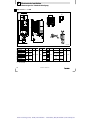
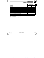
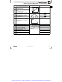
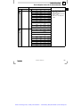
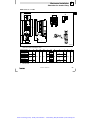
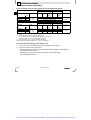
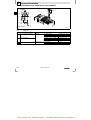
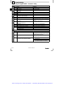
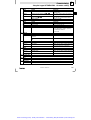
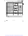
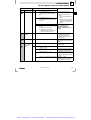
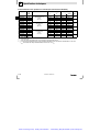
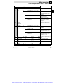
1
Artisan Technology Group is your source for quality new and certified-used/pre-owned equipment • FAST SHIPPING AND DELIVERY • TENS OF THOUSANDS OF IN-STOCK ITEMS • EQUIPMENT DEMOS • HUNDREDS OF MANUFACTURERS SUPPORTED • LEASING/MONTHLY RENTALS • ITAR CERTIFIED SECURE ASSET SOLUTIONS SERVICE CENTER REPAIRS Experienced engineers and technicians on staff at our full-service, in-house repair center WE BUY USED EQUIPMENT Sell your excess, underutilized, and idle used equipment We also offer credit for buy-backs and trade-ins www.artisantg.com/WeBuyEquipment InstraView REMOTE INSPECTION LOOKING FOR MORE INFORMATION? Visit us on the web at www.artisantg.com for more information on price quotations, drivers, technical specifications, manuals, and documentation SM Remotely inspect equipment before purchasing with our interactive website at www.instraview.com Contact us: (888) 88-SOURCE | [email protected] | www.artisantg.com Ä.1p}ä EDK82EV113 .1p} L Montageanleitung Mounting Instructions Instructions de montage L 8200vec062 Global Drive 8200 vector 3 kW ... 11 kW Artisan Technology Group - Quality Instrumentation ... Guaranteed | (888) 88-SOURCE | www.artisantg.com Lesen Sie zuerst die Montageanleitung, bevor Sie mit den Arbeiten beginnen! Beachten Sie die enthaltenen Sicherheitshinweise. Das Systemhandbuch mit ausführlicher Information zum Frequenzumrichter 8200 vector können Sie bei Ihrem Lenze−Vertriebspartner bestellen. Read the Mounting Instructions before you start working! Please observe all safety information given. The manual with detailed information about the 8200 vector can be ordered directly from Lenze or Lenze representatives. Lire attentivement les instructions de montage avant toute opération ! Respecter les consignes de sécurité. Le manuel comprenant une description complète du convertisseur de fréquence 8200 vector peut être commandé auprès de votre agence Lenze. 2007 Lenze Drive Systems GmbH 8.1 05/2007 TD29 Artisan Technology Group - Quality Instrumentation ... Guaranteed | (888) 88-SOURCE | www.artisantg.com X3.1 X1.2 X1.1 2 0 1 2 6 5 X2.1 X2.2 3 4 8200vec315 Artisan Technology Group - Quality Instrumentation ... Guaranteed | (888) 88-SOURCE | www.artisantg.com Lieferumfang Position Beschreibung Frequenzumrichter 8200 vector Montageanleitung und Start−Hilfe Halterung für Standardbefestigung 18 EMV−Schirmblech mit Schirmklammern für die Motorleitung und für die Zuleitung Motortemperatur− Überwachung 20 Klemmleiste 2−polig für Motor−PE und Motor−Schirm an X2.1 20 EMV−Schirmblech mit Befestigungsschrauben und Schirmschelle für geschirmte Steuerleitungen 20 Stiftleiste 2*13−polig für Funktionsmodule an Schnittstelle FIF 32 X1.1 Netzanschluß und DC-Einspeisung (integrierte Klemmleiste) Klemmleiste für Relaisausgang Motoranschluß, Anschluß Bremswiderstand (Option) (integrierte Klemmleiste) Klemmleiste für Anschluß PTC bzw. Thermokontakt (Öffner) des Motors Sonderausführung: Klemmleiste für Rückmeldekontakt − nur bei Variante "Sicherer Halt" E82EVxxxKxCx4x 22 25 29 X1.2 X2.1 X2.2 X3.1 28 30 Schnittstellen und Anzeigen Position Beschreibung Funktion 2 Leuchtdioden (rot, grün) Statusanzeige 76 Schnittstelle AIF (Automatisierungs−Interface) Steckplatz für Kommunikationsmodule 36 Keypad E82ZBC, Keypad XT EMZ9371BC Feldbusmodule Typ 21XX, z. B. INTERBUS 2111, PROFIBUS−DP 2133, ... Schnittstelle FIF (Funktions−Interface) Mit Abdeckkappe für den Betrieb ohne Funktionsmodule oder Steckplatz für Funktionsmodule 32 Standard−I/O E82ZAFSC Application−I/O E82ZAFAC Feldbus−Funktionsmodule Typ E82ZAFXC, z. B. INTERBUS E82ZAFIC, PROFIBUS−DP E82ZAFPC, ... Artisan Technology Group - Quality Instrumentation ... Guaranteed | (888) 88-SOURCE | www.artisantg.com Diese Dokumentation ist gültig für Antriebsregler 8200 vector für den Gerätestand E82xV xxx K x C xxx 3x 3x 55 Aerzen Hans-Lenze-Str. 1 D-31855 Aerzen Inverter 8200 vector Id.-No: Version: Ser.-No: Prod.-No: Input: Version: Ser.-No: 1D74 Industrial Control Equipment Typ E = Einbaugerät D = Einbaugerät in Durchstoßtechnik C = Einbaugerät in Cold Plate−Technik Output: For detailed information refer to the manual EDK82EV222 Made in Germany Type: Leistung (z. B. 152 = 15 102 W = 1.5 kW) (z. B. 113 = 11 103 W = 11 kW) _ K Spannungsklasse 2 = 230 V 4 = 400 V/500 V Geräte−Generation Ausführung, Variante 0xx = EMV−Filter integriert 1xx = für IT−Netze (15 ... 90 kW) 2xx = ohne EMV−Filter x0x = ohne Funktion "Sicherer Halt" x4x = mit Funktion "Sicherer Halt" (3 ... 90 kW) xx0 = nicht verlackt xx1 = verlackt Hardwarestand Softwarestand Artisan Technology Group - Quality Instrumentation ... Guaranteed | (888) 88-SOURCE | www.artisantg.com ) Hinweis! Aktuelle Dokumentationen und Software−Updates zu Lenze Produkten finden Sie im Internet jeweils im Bereich "Downloads" unter http://www.Lenze.com Artisan Technology Group - Quality Instrumentation ... Guaranteed | (888) 88-SOURCE | www.artisantg.com Inhalt Sicherheitshinweise . . . . . . . . . . . . . . . . . . . . . . . . . . . . . . . . . . . . . . . . . . . . . . . Technische Daten . . . . . . . . . . . . . . . . . . . . . . . . . . . . . . . . . . . . . . . . . . . . . . . . . Mechanische Installation . . . . . . . . . . . . . . . . . . . . . . . . . . . . . . . . . . . . . . . . . . . Abmessungen bei Standard−Befestigung . . . . . . . . . . . . . . . . . . . . . . . . . . . . . . . Elektrische Installation . . . . . . . . . . . . . . . . . . . . . . . . . . . . . . . . . . . . . . . . . . . . . Klemmleisten verdrahten . . . . . . . . . . . . . . . . . . . . . . . . . . . . . . . . . . . . . . . . . . EMV−gerechte Installation (CE−typisches Antriebssystem) . . . . . . . . . . . . . . . . . . . Netzanschluß 230 V/240 V . . . . . . . . . . . . . . . . . . . . . . . . . . . . . . . . . . . . . . . . . Netzanschluß 400 V/500 V . . . . . . . . . . . . . . . . . . . . . . . . . . . . . . . . . . . . . . . . . Anschluß Motor / Bremswiderstand . . . . . . . . . . . . . . . . . . . . . . . . . . . . . . . . . . Anschluß Relaisausgang . . . . . . . . . . . . . . . . . . . . . . . . . . . . . . . . . . . . . . . . . . Anschluß Relaisausgang KSR für "Sicherer Halt" . . . . . . . . . . . . . . . . . . . . . . . . . Funktionsmodul (Option) . . . . . . . . . . . . . . . . . . . . . . . . . . . . . . . . . . . . . . . . . . . . Montage . . . . . . . . . . . . . . . . . . . . . . . . . . . . . . . . . . . . . . . . . . . . . . . . . . . . . . Demontage . . . . . . . . . . . . . . . . . . . . . . . . . . . . . . . . . . . . . . . . . . . . . . . . . . . . Kommunikationsmodul (Option) . . . . . . . . . . . . . . . . . . . . . . . . . . . . . . . . . . . . . . Montage/Demontage . . . . . . . . . . . . . . . . . . . . . . . . . . . . . . . . . . . . . . . . . . . . . Inbetriebnahme . . . . . . . . . . . . . . . . . . . . . . . . . . . . . . . . . . . . . . . . . . . . . . . . . . . Vor dem ersten Einschalten . . . . . . . . . . . . . . . . . . . . . . . . . . . . . . . . . . . . . . . . Wahl der richtigen Betriebsart . . . . . . . . . . . . . . . . . . . . . . . . . . . . . . . . . . . . . . Mit dem Keypad E82ZBC − Parametrierung . . . . . . . . . . . . . . . . . . . . . . . . . . . . . Mit dem Keypad E82ZBC − Lineare U/f−Kennliniensteuerung . . . . . . . . . . . . . . . . . Mit dem Keypad E82ZBC − Vector−Regelung . . . . . . . . . . . . . . . . . . . . . . . . . . . . Mit dem Keypad XT EMZ9371BC − Parametrierung . . . . . . . . . . . . . . . . . . . . . . . . Mit dem Keypad XT EMZ9371BC − Lineare U/f−Kennliniensteuerung . . . . . . . . . . . Mit dem Keypad XT EMZ9371BC − Vector−Regelung . . . . . . . . . . . . . . . . . . . . . . Die wichtigsten Codes für die Inbetriebnahme . . . . . . . . . . . . . . . . . . . . . . . . . . . Störungen erkennen und beseitigen . . . . . . . . . . . . . . . . . . . . . . . . . . . . . . . . . . . Fehlverhalten des Antriebs . . . . . . . . . . . . . . . . . . . . . . . . . . . . . . . . . . . . . . . . . Störungsmeldungen . . . . . . . . . . . . . . . . . . . . . . . . . . . . . . . . . . . . . . . . . . . . . . L EDK82EV113 DE/EN/FR 8.1 i 8 14 18 18 19 19 20 22 25 28 29 30 32 32 34 36 36 37 37 38 40 46 48 51 58 60 64 74 74 76 7 Artisan Technology Group - Quality Instrumentation ... Guaranteed | (888) 88-SOURCE | www.artisantg.com 1 Sicherheitshinweise Allgemeine Sicherheits− und Anwendungshinweise für Lenze−Antriebsregler (gemäß Niederspannungsrichtlinie 73/23/EWG) Allgemein Lenze−Antriebsregler (Frequenzumrichter, Servo−Umrichter, Stromrichter) können während des Betriebs − ihrer Schutzart entsprechend − spannungsführende, auch bewegliche oder rotierende Teile haben. Oberflächen können heiß sein. Bei unzulässigem Entfernen der erforderlichen Abdeckung, bei unsachgemäßem Einsatz, bei falscher Installation oder Bedienung besteht die Gefahr von schweren Personen− oder Sachschäden. Weitere Informationen entnehmen Sie der Dokumentation. Alle Arbeiten zum Transport, zur Installation, zur Inbetriebnahme und zur Instandhaltung darf nur qualifiziertes Fachpersonal ausführen (IEC 364 bzw. CENELEC HD 384 oder DIN VDE 0100 und IEC−Report 664 oder DIN VDE 0110 und nationale Unfallverhütungsvorschriften beachten). Qualifiziertes Fachpersonal im Sinne dieser grundsätzlichen Sicherheitshinweise sind Personen, die mit Aufstellung, Montage, Inbetriebsetzung und Betrieb des Produkts vertraut sind und die über die ihrer Tätigkeit entsprechenden Qualifikationen verfügen. 8 EDK82EV113 DE/EN/FR 8.1 L Artisan Technology Group - Quality Instrumentation ... Guaranteed | (888) 88-SOURCE | www.artisantg.com Sicherheitshinweise 1 Bestimmungsgemäße Verwendung Antriebsregler sind Komponenten, die zum Einbau in elektrische Anlagen oder Maschinen bestimmt sind. Sie sind keine Haushaltsgeräte, sondern als Komponenten ausschließlich für die Verwendung zur gewerblichen Nutzung bzw. professionellen Nutzung im Sinne der EN 61000−3−2 bestimmt. Die Dokumentation enthält Hinweise zur Einhaltung der Grenzwerte nach EN 61000−3−2. Bei Einbau der Antriebsregler in Maschinen ist die Inbetriebnahme (d. h. die Aufnahme des bestimmungsgemäßen Betriebs) solange untersagt, bis festgestellt wurde, daß die Maschine den Bestimmungen der EG−Richtlinie 98/37/EG (Maschinenrichtlinie) entspricht; EN 60204 beachten. Die Inbetriebnahme (d. h. die Aufnahme des bestimmungsgemäßen Betriebs) ist nur bei Einhaltung der EMV−Richtlinie (89/336/EWG) erlaubt. Die Antriebsregler erfüllen die Anforderungen der Niederspannungsrichtlinie 73/23/EWG. Die harmonisierten Normen der Reihe EN 50178/DIN VDE 0160 werden für die Antriebsregler angewendet. Die technischen Daten und die Angaben zu Anschlußbedingungen entnehmen Sie dem Leistungsschild und der Dokumentation. Halten Sie sie unbedingt ein. Warnung: Die Antriebsregler sind Produkte mit eingeschränkter Erhältlichkeit nach EN 61800−3. Diese Produkte können im Wohnbereich Funkstörungen verursachen. In diesem Fall kann es für den Betreiber erforderlich sein, entsprechende Maßnahmen durchzuführen. Transport, Einlagerung Beachten Sie die Hinweise für Transport, Lagerung und sachgemäße Handhabung. Halten Sie die klimatischen Bedingungen nach EN 50178 ein. Aufstellung Sie müssen die Antriebsregler nach den Vorschriften der zugehörigen Dokumentation aufstellen und kühlen. Sorgen Sie für sorgfältige Handhabung und vermeiden Sie mechanische Überlastung. Verbiegen Sie bei Transport und Handhabung weder Bauelemente noch ändern Sie Isolationsabstände. Berühren Sie keine elektronischen Bauelemente und Kontakte. Antriebsregler enthalten elektrostatisch gefährdete Bauelemente, die Sie durch unsachgemäße Handhabung leicht beschädigen können. Beschädigen oder zerstören Sie keine elektrischen Komponenten, da Sie dadurch Ihre Gesundheit gefährden können! L EDK82EV113 DE/EN/FR 8.1 9 Artisan Technology Group - Quality Instrumentation ... Guaranteed | (888) 88-SOURCE | www.artisantg.com 1 Sicherheitshinweise Elektrischer Anschluß Beachten Sie bei Arbeiten an unter Spannung stehenden Antriebsreglern die geltenden nationalen Unfallverhütungsvorschriften (z. B. VBG 4). Führen Sie die elektrische Installation nach den einschlägigen Vorschriften durch (z. B. Leitungsquerschnitte, Absicherungen, Schutzleiteranbindung). Zusätzliche Hinweise enthält die Dokumentation. Die Dokumentation enthält Hinweise für die EMV−gerechte Installation (Schirmung, Erdung, Anordnung von Filtern und Verlegung der Leitungen). Beachten Sie diese Hinweise ebenso bei CE−gekennzeichneten Antriebsreglern. Der Hersteller der Anlage oder Maschine ist verantwortlich für die Einhaltung der durch die EMV−Gesetzgebung geforderten Grenzwerte. Betrieb Sie müssen Anlagen mit eingebauten Antriebsreglern ggf. mit zusätzlichen Überwachungs− und Schutzeinrichtungen gemäß den jeweils gültigen Sicherheitsbestimmungen ausrüsten (z. B. Gesetz über technische Arbeitsmittel, Unfallverhütungsvorschriften). Sie dürfen die Antriebsregler an Ihre Anwendung anpassen. Beachten Sie dazu die Hinweise in der Dokumentation. Nachdem der Antriebsregler von der Versorgungsspannung getrennt ist, dürfen Sie spannungsführende Geräteteile und Leistungsanschlüsse nicht sofort berühren, weil Kondensatoren aufgeladen sein können. Beachten Sie dazu die entsprechenden Hinweisschilder auf dem Antriebsregler. Halten Sie während des Betriebs alle Schutzabdeckungen und Türen geschlossen. Hinweis für UL−approbierte Anlagen mit eingebauten Antriebsreglern: UL warnings sind Hinweise, die nur für UL−Anlagen gelten. Die Dokumentation enthält spezielle Hinweise zu UL. Sicherer Halt−1− Die Variante V004 der Antriebsregler 9300 und 9300 vector, die Variante x4x der Antriebsregler 8200 vector und der Achsregler ECSxAxxx unterstützten die Funktion "Sicherer Halt", Schutz gegen unerwarteten Anlauf, nach den Anforderungen von Anhang I Nr. 1.2.7 der EG−Richtlinie "Maschinen" 98/37/EG, DIN EN 954−1 Kategorie 3 und DIN EN 1037. Beachten Sie unbedingt die Hinweise zur Funktion "Sicherer Halt" in der Dokumentation zu den Varianten. Wartung und Instandhaltung Beachten Sie die Hinweise in der Anleitung. Beachten Sie unbedingt die produktspezifischen Sicherheits− und Anwendungshinweise in dieser Anleitung! 10 EDK82EV113 DE/EN/FR 8.1 L Artisan Technology Group - Quality Instrumentation ... Guaranteed | (888) 88-SOURCE | www.artisantg.com Sicherheitshinweise 1 Personenschutz l Überprüfen Sie vor Arbeiten am Antriebsregler, ob alle Leistungsklemmen, der Relaisausgang und die Pins der Schnittstelle FIF spannungslos sind, da – nach dem Netzabschalten die Leistungsklemmen U, V, W, +UG, −UG, BR1 und BR2 noch mindestens 3 Minuten gefährliche Spannung führen. – bei gestopptem Motor die Leistungsklemmen L1, L2, L3; U, V, W, +UG, −UG, BR1 und BR2 gefährliche Spannung führen. – bei vom Netz getrenntem Antriebsregler die Relaisausgänge K11, K12, K14 gefährliche Spannung führen können. l Wenn Sie die nicht drahtbruchsichere Funktion QDrehrichtungsvorgabe" über das digitale Signal DCTRL1−CW/CCW verwenden (C0007 = 0 ... 13, C0410/3 255): – Bei Drahtbruch oder bei Ausfall der Steuerspannung kann der Antrieb die Drehrichtung wechseln. l Wenn Sie die Funktion "Fangschaltung" (C0142 = 2, 3) bei Maschinen mit geringem Massenträgheitsmoment und geringer Reibung verwenden: – Nach Reglerfreigabe im Stillstand kann der Motor kurzzeitig anlaufen oder kurzzeitig die Drehrichtung wechseln. l Die Betriebstemperatur des Kühlkörpers am Antriebsregler ist > 80 °C: – Hautkontakt mit dem Kühlkörper führt zu Verbrennungen. Geräteschutz l Alle steckbaren Anschlußklemmen nur im spannungslosen Zustand aufstecken oder abziehen! l Zyklisches Ein− und Ausschalten der Netzspannung kann die Eingangsstrombegrenzung des Antriebsreglers überlasten und zerstören: – Bei zyklischem Netzschalten über einen längeren Zeitraum müssen zwischen zwei Einschaltvorgängen mindestens drei Minuten vergehen! Motorschutz l Bei bestimmten Einstellungen der Antriebsregler kann der angeschlossene Motor überhitzt werden: – Z. B. längerer Betrieb der Gleichstrombremse. – Längerer Betrieb eigenbelüfteter Motoren bei kleinen Drehzahlen. L EDK82EV113 DE/EN/FR 8.1 11 Artisan Technology Group - Quality Instrumentation ... Guaranteed | (888) 88-SOURCE | www.artisantg.com 1 Sicherheitshinweise Schutz der Maschine/Anlage l Antriebe können gefährliche Überdrehzahlen erreichen (z. B. Einstellung hoher Ausgangsfrequenzen bei dafür ungeeigneten Motoren und Maschinen): – Die Antriebsregler bieten keinen Schutz gegen solche Betriebsbedingungen. Setzen Sie dafür zusätzliche Komponenten ein. l Schütze in der Motorleitung nur bei gesperrtem Regler schalten. Werden Schütze in der Motorleitung bei freigegebenem Regler geschaltet, – können Überwachungsfunktionen des Antriebsreglers ansprechen. – kann der Antriebsregler unter ungünstigen Betriebsbedingungen zerstört werden. Warnings! l The device has no overspeed protection. l Must be provided with external or remote overload protection. l Suitable for use on a circuit capable of delivering not more than 5000 rms symmetrical amperes, 240 V maximum (240 V devices) or 500 V maximum (400/500 V devices) resp. l Use 60/75 °C or 75 °C copper wire only. l Shall be installed in a pollution degree 2 macro−environment. 12 EDK82EV113 DE/EN/FR 8.1 L Artisan Technology Group - Quality Instrumentation ... Guaranteed | (888) 88-SOURCE | www.artisantg.com Sicherheitshinweise 1 Gestaltung der Sicherheitshinweise Alle Sicherheitshinweise in dieser Anleitung sind einheitlich aufgebaut: } Piktogramm (kennzeichnet die Art der Gefahr) Gefahr! (kennzeichnet die Schwere der Gefahr) Hinweistext (beschreibt die Gefahr und gibt Hinweise, wie sie vermieden werden kann) Piktogramm gefährliche elektrische Spannung Signalwort Bedeutung Unmittelbar drohende Gefahr für Personen Folgen bei Mißachtung Tod oder schwerste Verletzungen Warnung! Mögliche, sehr gefährliche Situation für Personen Tod oder schwerste Verletzungen Vorsicht! Mögliche, gefährliche Situation für Perso- Leichte Verletzungen nen Gefahr! allgemeine Gefahr L Stop! Hinweis! Mögliche Sachschäden Beschädigung des Antriebssystems oder seiner Umgebung Nützlicher Hinweis oder Tipp Wenn Sie ihn befolgen, erleichtern Sie sich die Handhabung des Antriebssystems. EDK82EV113 DE/EN/FR 8.1 13 Artisan Technology Group - Quality Instrumentation ... Guaranteed | (888) 88-SOURCE | www.artisantg.com 2 Technische Daten Normen und Einsatzbedingungen Normen Konformität Approbationen CE UL 508C Niederspannungsrichtlinie (73/23/EWG) Power Conversion Equipment (File−No. E132659) Umweltbedingungen Klimatische Bedingungen Lagerung IEC/EN 60721−3−1 1K3 (−25 ... +60 °C) 1K3 (−25 ... +40 °C) IEC/EN 60721−3−2 IEC/EN 60721−3−3 2K3 (−25 ... +70 °C) 3K3 (−10 ... +55 °C) 8200 vector 15 ... 90 kW: 3K3 (−10 ... +50 °C) Leisungsreduzierung ab +40 °C: 2,5 %/°C 0 ... 4000 m üNN Leistungsreduzierung ab 1000 m uNN: 5 %/1000 m Verschmutzungsgrad 2 Allgemeine Bedingungen: beschleunigungsfest bis 0,7g Transport Betrieb Aufstellhöhe Verschmutzung Rüttelfestigkeit Einsatzbedingungen Einbaulagen Einbaufreiräume oberhalb/unterhalb seitlich Zulässige max. Motorleitungslänge geschirmt ungeschirmt DC−Verbundbetrieb 14 EN 61800−5−1 Germanischer Lloyd < 6 Monate > 6 Monate > 2 Jahre: Zwischenkreis−Kondensatoren formieren vertikal 100 mm mit 3 mm Abstand anreihbar Bei Netz−Bemessungsspannung und Schaltfrequenz 8 kHz, ohne zusätzliche Ausgangsfilter 50 m Müssen EMV−Bedingungen eingehalten werden, können sich die zulässigen Leitungslängen ändern. 100 m möglich, außer E82xV251K2C und E82xV371K2C EDK82EV113 DE/EN/FR 8.1 L Artisan Technology Group - Quality Instrumentation ... Guaranteed | (888) 88-SOURCE | www.artisantg.com Technische Daten 2 Allgemeine elektrische Daten EMV Störaussendung Störfestigkeit Isolationsfestigkeit Ableitstrom gegen PE (nach EN 61800−5−1) Schutzart Schutzmaßnahmen gegen Schutzisolierung von Steuerschaltkreisen zulässige Netzformen Einhaltung der Anforderungen nach EN 61800−3/A11 Einhaltung der Grenzwertklassen A und B nach EN 55011 E82EVxxxKxC0xx ohne zusätzliche Maßnahmen E82EVxxxKxC2xx mit externen Filtermaßnahmen Anforderungen nach EN 61800−3 incl. A11 Anforderungen Norm Schärfegrade ESD EN 61000−4−2 3, d.S h. 8 kV bei Luftentladung, 6 kV bei Kontaktentladung leitungsgeführte HochfreEN 61000−4−6 150 kHz ... 80 MHz, quenz 10 V/m 80 % AM (1kHz) HF−Einstrahlung (Gehäuse) EN 61000−4−3 80 MHz ... 1000 MHz, 10 V/m 80 % AM (1kHz) Burst EN 61000−4−4 3/4, d.S h. 2 kV/5 kHz Surge EN 61000−4−5 3, d.S h. 1,2/50 s, (Stoßspannung auf Netzlei1 kV Phase−Phase, tung) 2 kV Phase−PE Überspannungskategorie III nach VDE 0110 > 3,5 mA, d. h. Festinstallation erforderlich, der PE muß doppelt ausgeführt sein IP20 Kurzschluß, Erdschluß (erdschlußfest im Betrieb, eingeschränkt erdschlußfest beim Netzeinschalten), Überspannung, Kippen des Motors, Motor−Übertemperatur (Eingang für PTC oder Thermokontakt, I2t−Überwachung) Sichere Trennung vom Netz: Doppelte/verstärkte Isolierung nach EN 61800−5−1 Betrieb an TT−Netzen, TN−Netzen oder Netzen mit geerdetem Mittelpunkt ohne zusätzliche Maßnahmen Betrieb an IT−Netzen nur möglich mit einer Variante zulässige Netzspannungsberei- Frequenzbereich che 45 Hz − 0 % … 65 Hz + 0S % DC−Einspeisung 1/N/PE AC 230/240 V 180 V − 0S % ... 264 V + 0S % DC 140 V − 0 % ... 370 V + 0 % 2/N/PE AC 230/240 V 3/PE AC 230/240 V 100 V − 0 S% ... 264 V + 0S % DC 140 V − 0 % ... 370 V + 0 % 3/PE AC 400 V 320 V − 0S % ... 440 V + 0 S% DC 450 V − 0 % ... 625 V + 0 % 3/PE AC 500 V 320 V − 0S % ... 550 V + 0 S% DC 450 V − 0 % ... 775 V + 0 % L EDK82EV113 DE/EN/FR 8.1 15 Artisan Technology Group - Quality Instrumentation ... Guaranteed | (888) 88-SOURCE | www.artisantg.com 2 Technische Daten Betrieb mit Bemessungsleistung (Normalbetrieb) Typ E82EV302K2C E82EV402K2C E82EV552K2C E82EV752K2C E82EV302K4C E82EV402K4C E82EV552K4C E82EV752K4C E82EV113K4C E82EV302K4C E82EV402K4C E82EV552K4C E82EV752K4C E82EV113K4C Leistung [kW] 3,0 4,0 5,5 7,5 3,0 4,0 5,5 7,5 11,0 3,0 4,0 5,5 7,5 11,0 Netz−Bemessungsspannung 3/PE AC 230/240 V 50 Hz DC 325 V 3/PE AC 400 V 50 Hz DC 565 V 3/PE AC 500 V 50 Hz DC 710 V Netzstrom [A] 15,6 21,3 29,3 − 9,0 12,3 16,8 21,5 − 7,2 9,8 13,4 17,2 − 12,0 16,0 21,0 28,0 7,0 8,8 12,0 15,0 21,0 5,6 7,0 9,6 12,0 16,8 Ausgangsstrom [A] 1)C IN Imax (60 s) 2) 12,0 16,5 22,5 28,6 7,3 9,5 13,0 16,5 23,5 5,8 7,6 10,4 13,2 18,8 18,0 24,8 33,8 42,9 11,0 14,2 19,5 24,8 35,3 11,0 14,2 19,5 24,8 35,3 Masse [kg] 2,9 3,6 2,9 3,6 2,9 3,6 ohne Netzdrossel mit Netzdrossel 1) 2) 16 Bei Netz−Bemessungsspannung und Schaltfrequenz 8 kHz Ströme für periodisches Lastwechselspiel: 1 min Überstromdauer mit Imax und 2 min Grundlastdauer mit 75 % INx EDK82EV113 DE/EN/FR 8.1 L Artisan Technology Group - Quality Instrumentation ... Guaranteed | (888) 88-SOURCE | www.artisantg.com Technische Daten 2 Betrieb mit erhöhter Bemessungsleistung Der Antriebsregler kann unter den hier beschriebenen Einsatzbedingungen im Dauerbetrieb mit einem leistungsstärkeren Motor betrieben werden. Die Überlastfähigkeit ist auf 120 % reduziert. Typische Anwendungen sind Pumpen mit quadratischer Lastkennlinie oder Lüfter. ) Hinweis! Der Betrieb mit erhöhter Bemessungsleistung ist nur erlaubt l mit den genannten Antriebsreglern l im genannten Netzspannungsbereich l mit den genannten Schaltfrequenzen l mit den vorgeschriebenen Sicherungen, Leitungsquerschnitten und Netzdrosseln Typ E82EV302K2C E82EV402K2C E82EV552K2C E82EV752K2C E82EV302K4C E82EV402K4C E82EV552K4C E82EV752K4C E82EV113K4C Leistung [kW] 3,0 4,0 5,5 7,5 3,0 4,0 5,5 7,5 11,0 Netz−Bemessungsspannung Netzstrom [A] 3/PE AC 230/240 V 50 Hz DC 325 V 3/PE AC 400 V 50 Hz DC 565 V 18,7 − 10,8 − − Ausgangsstrom [A] 1)C IN Imax (60 s) 2) 14,4 14,4 Betrieb nicht möglich 25,7 27 Betrieb nicht möglich 8,4 8,7 10,6 11,4 Betrieb nicht möglich 18,0 19,8 Betrieb nicht möglich 18,0 33,8 11,0 14,2 24,8 ohne Netzdrossel mit Netzdrossel 1) 2) Bei Netz−Bemessungsspannung und Schaltfrequenz 2 kHz oder 4 kHz Ströme für periodisches Lastwechselspiel: 1 min Überstromdauer mit Imax und 2 min Grundlastdauer mit 75 % INx L EDK82EV113 DE/EN/FR 8.1 17 Artisan Technology Group - Quality Instrumentation ... Guaranteed | (888) 88-SOURCE | www.artisantg.com 2 Mechanische Installation Abmessungen bei Standard−Befestigung 8200 vector 3 ... 11 kW > 100 mm 0 c1 a k c > 100 mm b3 b d b2 b1 g c2 e −2−8200vec060 Maße in mm E82EV302K2C E82EV402K2C E82EV552K2C 1) E82EV752K2C 1) E82EV302K4C E82EV402K4C E82EV552K4C E82EV752K4C 1) E82EV113K4C 1) 1) 2) 18 ÁÁÁ ÁÁÁ ÁÁ ÁÁÁ ÁÁÁ ÁÁÁ ÁÁÁ ÁÁÁ Unterschiedliche Baugrößen nur nach rechts kleiner werdend anreihen! a b 100 333 125 333 359 2) 100 333 b1 b2 b3 c 50 62,5 268 240 78 50 c1 103 103 128 128 103 103 103 128 128 c2 d e 255 140 255 280 ... 295 2) 140 162 2) 255 140 50 333 255 62,5 359 2) 280 ... 295 2) Seitliche Montage nur möglich mit schwenkbarer Halterung E82ZJ006 (Zubehör) mit E82ZJ006 125 EDK82EV113 DE/EN/FR 8.1 g k 6,5 28 140 162 2) L Artisan Technology Group - Quality Instrumentation ... Guaranteed | (888) 88-SOURCE | www.artisantg.com 3 Elektrische Installation Klemmleisten verdrahten Die mitgelieferten Klemmleisten sind geprüft nach den Spezifikationen der l DIN VDE 0627:1986−06 (in Teilen) DIN EN 60999:1994−04 (in Teilen) Geprüft wurden u. a. mechanische, elektrische und thermische Beanspruchung, Vibration, Leiterbeschädigung, Leiterlockerung, Korrosion und Alterung. l ( Stop! Um Klemmleisten und Kontakte des Antriebsreglers nicht zu beschädigen: l Nur bei vom Netz getrenntem Antriebsregler aufstecken oder abziehen! l Klemmleisten erst verdrahten, dann aufstecken! l Unbenutzte Klemmleisten ebenfalls aufstecken, um die Kontakte zu schützen. 8200vec015 ) Hinweis! Verdrahtung ohne Aderendhülsen ist uneingeschränkt zulässig. L EDK82EV113 DE/EN/FR 8.1 19 Artisan Technology Group - Quality Instrumentation ... Guaranteed | (888) 88-SOURCE | www.artisantg.com 3 Elektrische Installation EMV−gerechte Installation (CE−typisches Antriebssystem) 0 1 PE PES 2 3 4 PE 5 PE 6 M 3~ PES 8 9 7 L < 40 mm L < 500 mm PES −3−8200vec066 20 EDK82EV113 DE/EN/FR 8.1 L Artisan Technology Group - Quality Instrumentation ... Guaranteed | (888) 88-SOURCE | www.artisantg.com Elektrische Installation EMV−gerechte Installation (CE−typisches Antriebssystem) ( Stop! l l l l l 3 Steuerleitungen und Netzleitungen räumlich getrennt von der Motorleitung verlegen, um Störeinkopplungen zu vermeiden. Steuerleitungen immer geschirmt ausführen. Generell empfehlen wir, die Zuleitung zum PTC oder Thermokontakt abgeschirmt und räumlich getrennt von der Motorleitung zu verlegen. Wenn Sie die Adern für den Motoranschluß und die Adern für den Anschluß des PTC oder Thermokontakts in einem Kabel mit gemeinsamem Schirm führen: – Um Störeinkopplungen auf die PTC−Leitung zu reduzieren, empfehlen wir, zusätzlich das PTC−Modul Typ E82ZPE zu installieren. Bestmögliche HF−Schirmverbindung der Motorleitung erreichen Sie durch Einsatz der Klemme für Motor−PE und Motor−Schirm. Montageplatte mit elektrisch leitender Oberfläche Steuerleitung zum Funktionsmodul, Schirmung großflächig auf dem EMV−Schirmblech (PES) auflegen Klemme 2−polig für Motor−PE und Motor−Schirm PE der Motorleitung Schirm der Motorleitung geschirmte Motorleitung, kapazitätsarm (Ader/Ader bis 1,5 mm2 75 pF/m; ab 2,5 mm2 100 pF/m; Ader/Schirm 150 pF/m) geschirmte PTC−Leitung oder Thermokontaktleitung Leitungsschirme großflächig auf dem EMV−Schirmblech (PES) auflegen. Beiliegende Schnell−Schirmschellen verwenden. Stern− oder Dreieckschaltung wie auf dem Motor−Typenschild angegeben EMV-Kabelverschraubung (nicht im Lieferumfang enthalten) L EDK82EV113 DE/EN/FR 8.1 21 Artisan Technology Group - Quality Instrumentation ... Guaranteed | (888) 88-SOURCE | www.artisantg.com 3 Elektrische Installation ( Stop! Netzanschluß 230 V/240 V l l Antriebsregler Typ E82EVxxxK2C nur an Netzspannung 3/PE AC 100 ... 264 V anschließen. Höhere Netzspannung zerstört den Antriebsregler! Der Ableitstrom gegen Erde (PE) ist > 3.5 mA. Nach EN 50178 ist eine Festinstallation erforderlich. Der PE muß doppelt ausgeführt sein. X1.1 3 PE AC 230/240 V 45Hz -0%...65Hz +0% 100 V -0%...264 V +0% L1 L2 L3 N PE 0,7...0,8 Nm 6.2...7.1 lb-in 6 mm / 0.24 in X1.1 PE L1 L2 L3 +UG -UG E82EVXXXK2C −4−8200vec065 E82EV752K2C Betrieb nur erlaubt mit Netzdrossel X1.1/+UG, X1.1/−UG DC−Einspeisung (DC−Verbundbetrieb siehe Betriebsanleitung) 22 EDK82EV113 DE/EN/FR 8.1 L Artisan Technology Group - Quality Instrumentation ... Guaranteed | (888) 88-SOURCE | www.artisantg.com 3 Elektrische Installation Netzanschluß 230 V/240 V Sicherungen und Leitungsquerschnitte (Betrieb mit Bemessungsleistung) Betrieb ohne Netzdrossel Installation nach EN 60204−1 Installation nach UL 1) 8200 vector Typ E82EV302K2C E82EV402K2C E82EV552K2C E82EV752K2C Netz [kW] W3,0W W4,0W W5,5W W7,5W 3/PE AC 100 ... 264 V; 45 ... 65 Hz M20 A M25 A M35 A L1, L2, L3, PE [mm2] B20 A 4 20 A B25 A 4 25 A − 6 4) 35 A Betrieb nur erlaubt mit Netzdrossel L1, L2, L3, PE [AWG] 12 10 8 FI 300 mA 2) 30 mA 3) Betrieb mit Netzdrossel Installation nach EN 60204−1 Installation nach UL 1) 8200 vector Typ E82EV302K2C E82EV402K2C E82EV552K2C E82EV752K2C Netz [kW] W3,0W W4,0W W5,5W W7,5W 3/PE AC 100 ... 264 V; 45 ... 65 Hz M16 A M20 A M25 A M35 A B16 A B20 A B25 A − L1, L2, L3, PE [mm2] 2,5 4 4 6 4) 15 A 20 A 25 A 35 A L1, L2, L3, PE [AWG] 14 12 10 8 FI 300 mA 2) 30 mA 3) Schmelzsicherung Sicherungsautomat 1) Nur UL−approbierte Leitungen, Sicherungen und Sicherungshalter verwenden. UL−Sicherung: Spannung 240 V, Auslösecharakteristik "H", "K5" oder "CC" 2) Allstromsensitiver Fehlerstrom−Schutzschalter für Einsatz mit E82EVxxxK2C0xx 3) Allstromsensitiver Fehlerstrom−Schutzschalter für Einsatz mit E82EVxxxK2C2xx 4) Anschluß flexibler Leitungen nur mit Stiftkabelschuh möglich Nationale und regionale Vorschriften beachten (z. B. VDE 0113, EN 60204) L EDK82EV113 DE/EN/FR 8.1 23 Artisan Technology Group - Quality Instrumentation ... Guaranteed | (888) 88-SOURCE | www.artisantg.com 3 Elektrische Installation Netzanschluß 230 V/240 V Sicherungen und Leitungsquerschnitte (Betrieb mit erhöhter Bemessungsleistung) Betrieb ohne Netzdrossel Installation nach EN 60204−1 Installation nach UL 1) 8200 vector Netz Typ E82EV302K2C [kW] W3,0W E82EV552K2C W5,5W M25 A B25 A L1, L2, L3, PE [mm2] 3/PE AC 100 ... 264 V; 45 ... 65 Hz 4 L1, L2, L3, PE FI [AWG] 25 A 10 Betrieb nur erlaubt mit Netzdrossel 300 mA 2) 30 mA 3) Betrieb mit Netzdrossel Installation nach EN 60204−1 Installation nach UL 1) 8200 vector Netz Typ E82EV302K2C [kW] W3,0W E82EV552K2C W5,5W M20 A B20 A 4 20 A 12 M32 A B32 A 6 4) 35 A 8 L1, L2, L3, PE [mm2] 3/PE AC 100 ... 264 V; 45 ... 65 Hz L1, L2, L3, PE FI [AWG] 300 mA 2) 30 mA 3) Schmelzsicherung Sicherungsautomat 1) Nur UL−approbierte Leitungen, Sicherungen und Sicherungshalter verwenden. UL−Sicherung: Spannung 240 V, Auslösecharakteristik "H", "K5" oder "CC" 2) Allstromsensitiver Fehlerstrom−Schutzschalter für Einsatz mit E82EVxxxK2C0xx 3) Allstromsensitiver Fehlerstrom−Schutzschalter für Einsatz mit E82EVxxxK2C2xx 4) Anschluß flexibler Leitungen nur mit Stiftkabelschuh möglich Nationale und regionale Vorschriften beachten (z. B. VDE 0113, EN 60204) Beachten Sie bei Einsatz von Fehlerstrom−Schutzschaltern: l Fehlerstrom−Schutzschalter nur zwischen speisendem Netz und Antriebsregler installieren. l Fehlerstrom−Schutzschalter kann falsch auslösen durch – kapazitive Ausgleichsströme der Leitungsschirme während des Betriebs (vor allem bei langen, geschirmten Motorleitungen), – gleichzeitiges Zuschalten mehrerer Antriebsregler ans Netz, – Einsatz zusätzlicher Entstörfilter. 24 EDK82EV113 DE/EN/FR 8.1 L Artisan Technology Group - Quality Instrumentation ... Guaranteed | (888) 88-SOURCE | www.artisantg.com Elektrische Installation Netzanschluß 400 V/500 V ( 3 Stop! l l Antriebsregler Typ E82EVxxxK4C nur an Netzspannung 3/PE AC 320 ... 550 V anschließen. Höhere Netzspannung zerstört den Antriebsregler! Der Ableitstrom gegen Erde (PE) ist > 3.5 mA. Nach EN 50178 ist eine Festinstallation erforderlich. Der PE muß doppelt ausgeführt sein. X1.1 3 PE AC 400 V 45 Hz -0 %...65 Hz +0 % 320 V -0 %...550 V +0 % L1 L2 L3 N PE 0,7...0,8 Nm 6.2...7.1 lb-in 6 mm / 0.24 in X1.1 PE L1 L2 L3 +UG -UG E82EVXXXK4C −5−8200vec067 X1.1/+UG, X1.1/−UG L DC−Einspeisung (DC−Verbundbetrieb siehe Betriebsanleitung) EDK82EV113 DE/EN/FR 8.1 25 Artisan Technology Group - Quality Instrumentation ... Guaranteed | (888) 88-SOURCE | www.artisantg.com 3 Elektrische Installation Netzanschluß 400 V/500 V Sicherungen und Leitungsquerschnitte (Betrieb mit Bemessungsleistung) Betrieb ohne Netzdrossel Installation nach EN 60204−1 Installation nach UL 1) 8200 vector Typ E82EV302K4C E82EV402K4C E82EV552K4C E82EV752K4C E82EV113K4C Netz [kW] W3,0W W4,0W W5,5W W7,5W 11 3/PE AC 320 ... 550 V; 45 ... 65 Hz M16 A M16 A M25 A M32 A L1, L2, L3, PE [mm2] B16 A 2,5 15 A B16 A 2,5 15 A B25 A 4 20 A B32 A 6 4) 25 A Betrieb nur erlaubt mit Netzdrossel L1, L2, L3, PE [AWG] 14 14 12 10 FI 300 mA 2) 30 mA 3) Betrieb mit Netzdrossel Installation nach EN 60204−1 Installation nach UL 1) 8200 vector Typ E82EV302K4C E82EV402K4C E82EV552K4C E82EV752K4C E82EV113K4C Netz [kW] W3,0W W4,0W W5,5W W7,5W 11 3/PE AC 320 ... 550 V; 45 ... 65 Hz M10 A M16 A M20 A M20 A M32 A B10 A B16 A B20 A B20 A B32 A L1, L2, L3, PE [mm2] 1,5 2,5 4 4 6 4) 10 A 15 A 20 A 20 A 25 A L1, L2, L3, PE [AWG] 16 14 12 12 10 FI 300 mA 2) 30 mA 3) Schmelzsicherung Sicherungsautomat 1) Nur UL−approbierte Leitungen, Sicherungen und Sicherungshalter verwenden. UL−Sicherung: Spannung 500 ... 600 V, Auslösecharakteristik "H", "K5" oder "CC" 2) Allstromsensitiver Fehlerstrom−Schutzschalter für Einsatz mit E82EVxxxK4C0xx 3) Allstromsensitiver Fehlerstrom−Schutzschalter für Einsatz mit E82EVxxxK4C2xx 4) Anschluß flexibler Leitungen nur mit Stiftkabelschuh möglich Nationale und regionale Vorschriften beachten (z. B. VDE 0113, EN 60204) 26 EDK82EV113 DE/EN/FR 8.1 L Artisan Technology Group - Quality Instrumentation ... Guaranteed | (888) 88-SOURCE | www.artisantg.com 3 Elektrische Installation Netzanschluß 400 V/500 V Sicherungen und Leitungsquerschnitte (Betrieb mit erhöhter Bemessungsleistung) Betrieb ohne Netzdrossel Installation nach EN 60204−1 Installation nach UL 1) 8200 vector Typ E82EV302K4C E82EV402K4C E82EV752K4C Netz [kW] W3,0W W4,0W W7,5W 3/PE AC 320 ... 440 V; 45 ... 65 Hz M16 A L1, L2, L3, L1, L2, L3, PE PE [mm2] [AWG] B16 A 2,5 15 A 14 Betrieb nur erlaubt mit Netzdrossel Betrieb nur erlaubt mit Netzdrossel FI 300 mA 2) 30 mA 3) Betrieb mit Netzdrossel Installation nach EN 60204−1 Installation nach UL 1) 8200 vector Typ E82EV302K4C E82EV402K4C E82EV752K4C Netz [kW] W3,0W W4,0W W7,5W 3/PE AC 320 ... 440 V; 45 ... 65 Hz M10 A M16 A M25 A B10 A B16 A B25 A L1, L2, L3, PE [mm2] 1,5 2,5 4 10 A 15 A 25 A L1, L2, L3, PE [AWG] 16 14 10 FI 300 mA 2) 30 mA 3) Schmelzsicherung Sicherungsautomat 1) Nur UL−approbierte Leitungen, Sicherungen und Sicherungshalter verwenden. UL−Sicherung: Spannung 500 ... 600 V, Auslösecharakteristik "H", "K5" oder "CC" 2) Allstromsensitiver Fehlerstrom−Schutzschalter für Einsatz mit E82EVxxxK4C0xx 3) Allstromsensitiver Fehlerstrom−Schutzschalter für Einsatz mit E82EVxxxK4C2xx Nationale und regionale Vorschriften beachten (z. B. VDE 0113, EN 60204) Beachten Sie bei Einsatz von Fehlerstrom−Schutzschaltern: l Fehlerstrom−Schutzschalter nur zwischen speisendem Netz und Antriebsregler installieren. l Fehlerstrom−Schutzschalter kann falsch auslösen durch – kapazitive Ausgleichsströme der Leitungsschirme während des Betriebs (vor allem bei langen, geschirmten Motorleitungen), – gleichzeitiges Zuschalten mehrerer Antriebsregler ans Netz, – Einsatz zusätzlicher Entstörfilter. L EDK82EV113 DE/EN/FR 8.1 27 Artisan Technology Group - Quality Instrumentation ... Guaranteed | (888) 88-SOURCE | www.artisantg.com 4 Elektrische Installation Anschluß Motor / Bremswiderstand 0,7...0,8 Nm 6.2...7.1 lb-in 6 mm / 0.24 in } 8200 vector X2.1 U V W BR1 BR2 PE X2.2 T1 T2 PES PES PES PES PES PE PE X2.1 PES PES ϑ> M 3~ PE M 3~ PE U VW Br1 Br2 PE X2.2 T1 PES T2 PTC −6−8200vec064 Kapazitätsarme Motorleitungen verwenden! (Ader/Ader bis 1,5 mm2 75 pF/m; ab 2,5 mm2 100 pF/m; Ader/Schirm 150 pF/m) Möglichst kurze Motorleitungen wirken sich positiv auf das Antriebsverhalten aus! PES HF−Schirmabschluß durch PE−Anbindung über Schirmschelle bzw. EMV−Kabelverschraubung X2.1/PE Ausgangsseitige Erdung des 8200 vector X2.1/BR1, Anschlußklemmen Bremswiderstand X2.1/BR2 (Informationen zum Betrieb mit Bremswiderstand: siehe Betriebsanleitung) X2.2/T1, X2.2/T2 Anschlußklemmen Motortemperatur−Überwachung mit Kaltleiter (PTC) oder Thermokontakt Motortemperatur−Überwachung mit C0119 aktivieren (z. B. C0119 = 1)! Leitungsquerschnitte U, V, W, PE Typ mm2 E82EV302K2C 2,5 E82EV402K2C 4 E82EV552K2C 6 E82EV752K2C 6 Typ E82EV302K4C E82EV402K4C E82EV552K4C E82EV752K4C E82EV113K4C mm2 1 1.5 2.5 4 4 AWG 16 14 12 10 10 Gefahr! l l 28 AWG 12 10 10 10 Alle Steuerklemmen sind nach dem Anschluß eines Kaltleiters (PTC) oder eines Thermokontakts nur noch basisisoliert (einfache Trennstrecke). Berührsicherheit bei defekter Trennstrecke ist nur durch externe Maßnahmen gewährleistet, z. B. doppelte Isolierung. EDK82EV113 DE/EN/FR 8.1 L Artisan Technology Group - Quality Instrumentation ... Guaranteed | (888) 88-SOURCE | www.artisantg.com Elektrische Installation Anschluß Relaisausgang 5 −7−8200vec061 Funktion X1.2/K11 X1.2/K12 X1.2/K14 PES ) Relaisstellung geschaltet geöffnet Meldung (Lenze−Einstellung) TRIP Relaisausgang Öffner Relais−Mittelkontakt Relaisausgang Schließer geschlossen HF−Schirmabschluß durch PE−Anbindung über Schirmschelle TRIP Technische Daten AC 250 V/3 A DC 24 V/2 A ... DC 240 V/0.16 A Hinweis! l l l l l L Für das Schalten von Steuersignalen geschirmte Leitungen verwenden und HF−Schirmabschluß durch PE−Anbindung herstellen. Für das Schalten von Netzpotentialen sind ungeschirmte Leitungen ausreichend. Zum Schutz der Relaiskontakte ist bei induktiver oder kapazitver Last eine entsprechende Schutzbeschaltung unbedingt notwendig! Die Lebensdauer des Relais ist abhängig von der Art der Belastung (ohmsch, induktiv oder kapazitiv) und dem Wert der Schaltleistung. Die ausgegebene Meldung können Sie in den Codestellen C0008 oder C0415/1 ändern. EDK82EV113 DE/EN/FR 8.1 29 Artisan Technology Group - Quality Instrumentation ... Guaranteed | (888) 88-SOURCE | www.artisantg.com 5 Elektrische Installation Anschluß Relaisausgang KSR für "Sicherer Halt" (nur aktiv bei Variante E82EVxxxK4Cx4x)−8− Die Variante x4x der Antriebsregler unterstützt die Sicherheitsfunktion "Sicherer Halt", Schutz gegen unerwarteten Anlauf, nach den Anforderungen der EN 954−1 QSteuerungskategorie 3" und EN 1037. Dafür sind die Antriebsregler mit einem integrierten Sicherheitsrelais mit Rückmeldekontakt ausgestattet. Das Sicherheitsrelais schaltet die Spannungsversorgung der Optokoppler zur Impulsübertragung an die IGBT galvanisch ab. Es muß von extern mit DC +24 V angesteuert werden. l Nur qualifiziertes Personal darf die Funktion "Sicherer Halt" installieren und in Betrieb nehmen. l Alle sicherheitsrelevanten externen Leitungen (z. B. Ansteuerleitung für das Sicherheitsrelais, Rückmeldekontakt) unbedingt geschützt verlegen, z. B. im Kabelkanal. Kurzschlüsse und Querschlüsse dabei sicher ausschließen! l Bei äußerer Krafteinwirkung auf die Antriebsachsen sind zusätzliche Bremsen erforderlich. Beachten Sie besonders die Wirkung der Schwerkraft auf hängende Lasten! l Nach der Erstinbetriebnahme muß der Betreiber die Funktion der Sicherheitsstromkreise prüfen, danach in regelmäßigen Zeitabständen. } Gefahr! l l 30 Der elektrische Bezugspunkt für die Spule des Sicherheitsrelais muß mit dem Schutzleitersystem verbunden sein (DIN EN 60204−1 Abs. 9.4.3)! – Nur so ist der Schutz gegen fehlerhaften Betrieb durch Erdschlüsse gewährleistet. Mit der Funktion "Sicherer Halt" ist ohne zusätzliche Maßnahmen kein "Not−Aus" möglich: – Zwischen Motor und Antriebsregler gibt es keine galvanische Trennung, keinen "Serviceschalter" oder "Reparaturschalter" – Für ein "Not−Aus" ist eine galvanische Trennung erforderlich, z. B. durch ein zentrales Netzschütz! EDK82EV113 DE/EN/FR 8.1 L Artisan Technology Group - Quality Instrumentation ... Guaranteed | (888) 88-SOURCE | www.artisantg.com Elektrische Installation Anschluß Relaisausgang KSR für "Sicherer Halt" 33 K 32 K 31 = 34 DC +24V 5 X3.1 + X3.1 34 33 K32 K31 KSR +5V 8200 vector IGBT 8200vec266 Klemmenbelegung Daten 33 Bezugspotential für den Eingang Si- Sicherheitsrelais cherheitsabschaltung 34 Eingang Sicherheitsabschaltung K31 K32 Rückmeldekontakt L Rückmeldekontakt Spulenspannung bei +40°C Spulenstrom bei 24 V DC Prüfspannung Kontakt Spule Prüfspannung Kontakt Kontakt Elektr. Lebensdauer bei Nennlast Mechanische Lebensdauer Schaltspannung Dauerstrom EDK82EV113 DE/EN/FR 8.1 DC +24 V (+19.5 ... 36 V) 30 mA AC 1500 Veff für 1 min AC 1500 Veff für 1 min ~ 107 Schaltspiele ~ 107 Schaltspiele DC 24 V 5 ... 700 mA 31 Artisan Technology Group - Quality Instrumentation ... Guaranteed | (888) 88-SOURCE | www.artisantg.com 6 Funktionsmodul (Option) Montage Wichtige Hinweise Die Antriebsregler haben in der Grundausführung keine Steuerklemmen. Es stehen verschiedene I/O−Funktionsmodule für die Schnittstelle FIF zur Verfügung, um die Antriebsregler mit Steuerklemmen auszustatten. Demontieren Sie ein Funktionsmodul nur, wenn es unbedingt notwendig ist (z. B. beim Austausch des Antriebsreglers). Die Stiftleiste, auf die das Funktionsmodul aufgesteckt wird, ist Teil der Kontaktführung des Antriebsreglers. Sie ist nicht ausgelegt für wiederholtes Aufstecken und Abnehmen des Funktionsmoduls! Montage von Funktionsmodulen OFF 3 min 0 3 2 1 −9−8200vec072 1. Antriebsregler vom Netz trennen und mindestens 3 Minuten warten! 2. FIF−Abdeckkappe entfernen und aufbewahren. 3. Schutzkappe des Funktionsmoduls entfernen. 4. Funktionsmodul auf die FIF−Schnittstelle stecken. 5. Stiftleiste bis zum Einrasten in die Kontaktleiste des Funktionsmoduls stecken. 6. Verdrahtung: siehe Montageanleitung des Funktionsmoduls 32 EDK82EV113 DE/EN/FR 8.1 L Artisan Technology Group - Quality Instrumentation ... Guaranteed | (888) 88-SOURCE | www.artisantg.com Funktionsmodul (Option) Montage 6 Montage von Funktionsmodulen in Ausführung "PT" 4 −10−8200vec372 Bringen Sie zusätzlich den Sicherungsbügel an, damit das Modul nicht zusammen mit den Klemmleisten abgezogen werden kann: 1. Sicherungsbügel in die Aussparungen einsetzen. 2. Sicherungsbügel über das Funktionsmodul klappen und einrasten. L EDK82EV113 DE/EN/FR 8.1 33 Artisan Technology Group - Quality Instrumentation ... Guaranteed | (888) 88-SOURCE | www.artisantg.com 6 Funktionsmodul (Option) Demontage Demontage der Funktionsmodule 3 min 0 OFF 8200vec072 1. Antriebsregler vom Netz trennen und mindestens 3 Minuten warten! 2. Mit einer Zange den Steg der Stiftleiste fassen und ziehen . Stiftleiste und Funktionsmodul werden gemeinsam demontiert. 34 EDK82EV113 DE/EN/FR 8.1 L Artisan Technology Group - Quality Instrumentation ... Guaranteed | (888) 88-SOURCE | www.artisantg.com 6 Funktionsmodul (Option) Demontage Demontage der Funktionsmodule Ausführung "PT" 0 1 2 8200vec372 Bei Funktionsmodulen Ausführung "PT" muss nach dem Abschalten zunächst der Sicherungsbügel entfernt werden. 1. Schraubendreher zwischen Sicherungsbügel und Funktionsmodul ansetzen . Durch Drücken nach rechts den Sicherungsbügel ausrasten. 2. Sicherungsbügel nach rechts schwenken. 3. Mit einer Zange den Steg der Stiftleiste fassen und ziehen . Stiftleiste und Funktionsmodul werden gemeinsam demontiert. L EDK82EV113 DE/EN/FR 8.1 35 Artisan Technology Group - Quality Instrumentation ... Guaranteed | (888) 88-SOURCE | www.artisantg.com 6 Kommunikationsmodul (Option) Montage/Demontage 0 0 −11−8200vec073 Jumper zur Auswahl der Spannungsversorgung Spannungsversorgung extern (Lieferzustand) Spannungsversorgung über interne Spannungsquelle Kommunikationsmodul auf die Schnittstelle AIF aufstecken bzw. davon abziehen. Das ist auch während des Betriebs möglich. Mögliche Kombinationen Funktionsmodul auf FIF (Ausführung: Standard oder PT) Kommunikationsmodul auf AIF Keypad E82ZBC 1) Keypad XT EMZ9371BC 1) LECOM −A/B 2102.V001 −LI 2102.V003 −A 2102.V004 1) LECOM−B (RS485) 2102.V002 INTERBUS 2111/2113 INTERBUS− Loop 2112 PROFIBUS− DP 2131/2133 Systembus (CAN) 2171/2172 CANopen / DeviceNet 2175 LON 2141 üü Standard−I/O E82ZAFSC üü üü üü üü üü üü üü Application−I/O E82ZAFAC üü ü ü ü ü ü ü ü INTERBUS E82ZAFIC üü (ü) x x x x x x PROFIBUS−DP E82ZAFPC üü (ü) x x x x x x LECOM−B (RS485) E82ZAFLC üü (ü) x x x x x x Systembus (CAN) Systembus I/O−RS Systembus I/O E82ZAFCC E82ZAFCC100 E82ZAFCC200 üü üü üü üü üü üü üü üü E82ZAFD üü üü x x x x x x E82ZAFFC üü üü x x x x x x CANopen / AS−i 1) 2) üü ü (ü) x 36 DeviceNet 2) Wird unabhängig von der Jumperstellung immer über die interne Spannungsqelle versorgt. in Vorbereitung Kombination möglich, Kommunikationsmodul wird intern oder extern versorgt Kombination möglich, Kommunikationsmodul muß extern versorgt werden! Kombination möglich, Kommunikationsmodul kann nur zum Parametrieren verwendet werden (intern oder extern versorgt) Kombination nicht möglich EDK82EV113 DE/EN/FR 8.1 L Artisan Technology Group - Quality Instrumentation ... Guaranteed | (888) 88-SOURCE | www.artisantg.com Inbetriebnahme Vor dem ersten Einschalten ) 7 Hinweis! l l Halten Sie die jeweilige Einschaltreihenfolge ein. Bei Störungen während der Inbetriebnahme hilft Ihnen das Kapitel "Störungen erkennen und beseitigen". Um Personenschäden oder Sachschäden zu vermeiden, überprüfen Sie ... ... vor dem Zuschalten der Netzspannung: l Die Verdrahtung auf Vollständigkeit, Kurzschluß und Erdschluß l Die Funktion "NOT−AUS" der Gesamtanlage l Die Schaltungsart des Motors (Stern/Dreieck) muß an die Ausgangsspannung des Antriebsreglers angepaßt sein. l Wenn kein Funktionsmodul verwendet wird, muß die FIF−Abdeckkappe aufgesteckt sein (Lieferzustand). Wenn die interne Spannungsquelle X3/20 z. B. des Standard−I/O verwendet wird, müssen die Klemmen X3/7 und X3/39 gebrückt sein. ... vor der Reglerfreigabe die Einstellung der wichtigsten Antriebsparameter: l l Sind die für Ihre Anwendung relevanten Antriebsparameter richtig eingestellt? – Z. B. die Konfiguration der analogen und digitalen Eingänge und Ausgänge L EDK82EV113 DE/EN/FR 8.1 37 Artisan Technology Group - Quality Instrumentation ... Guaranteed | (888) 88-SOURCE | www.artisantg.com 7 Inbetriebnahme Wahl der richtigen Betriebsart Für Standardanwendungen hilft Ihnen die folgende Tabelle, die richtige Betriebsart zu wählen. Sie können wählen zwischen U/f−Kennliniensteuerung, Vector−Regelung und sensorloser Drehmoment−Regelung: Die U/f−Kennliniensteuerung ist die klassische Betriebsart für Standardanwendungen. Mit der Vector−Regelung erzielen Sie gegenüber der U/f−Kennliniensteuerung verbesserte Antriebseigenschaften durch: l höheres Drehmoment über den gesamten Drehzahlbereich l höhere Drehzahlgenauigkeit und höhere Rundlaufgüte l höheren Wirkungsgrad U/f−Kennliniensteuerung Vector−Regelung 38 EDK82EV113 DE/EN/FR 8.1 L Artisan Technology Group - Quality Instrumentation ... Guaranteed | (888) 88-SOURCE | www.artisantg.com 7 Inbetriebnahme Wahl der richtigen Betriebsart Anwendung Betriebsart Einzelantriebe mit stark wechselnden Lasten mit Schweranlauf mit Drehzahlregelung (Drehzahlrückführung) mit hoher Dynamik (z. B. Positionier− und Zustellantriebe) mit Drehmoment−Sollwert mit Drehmomentbegrenzung (Leistungsregelung) Drehstrom−Reluktanzmotoren Drehstrom−Verschiebeankermotoren Drehstrommotoren mit fest zugeordneter Frequenz−Spannungskennlinie Pumpen− und Lüfterantriebe mit quadratischer Lastkennlinie Gruppenantriebe (mehrere Motoren an einem Antriebsregler angeschlossen) gleiche Motoren und gleiche Lasten unterschiedliche Motoren und/oder wechselnde Lasten Einstellung in C0014 empfohlen alternativ 4 2 4 2 2 4 2 − 5 − 2 4 2 − 2 − 2 − 3 2 oder 4 2 2 − − C0014 = 2: lineare U/f−Kennliniensteuerung C0014 = 3: quadratische U/f−Kennliniensteuerung C0014 = 4: Vector−Regelung C0014 = 5: sensorlose Drehmoment−Regelung L EDK82EV113 DE/EN/FR 8.1 39 Artisan Technology Group - Quality Instrumentation ... Guaranteed | (888) 88-SOURCE | www.artisantg.com 7 Inbetriebnahme Mit dem Keypad E82ZBC − Parametrierung Beschreibung Das Keypad ist als Zubehör erhältlich. Die vollständige Beschreibung des Keypad finden Sie in der Anleitung, die mit dem Keypad geliefert wird. Keypad aufstecken Sie können das Keypad auch während des Betriebs auf die Schnittstelle AIF stecken und wieder abnehmen. Sobald das Keypad mit Spannung versorgt wird, führt es einen Selbsttest aus. Das Keypad ist betriebsbereit, wenn es sich im Anzeigemodus befindet. 1 3 4 2 Anzeigemodus 5 6 7 8 d c b e a j g f k i h PS m n op 8888 888 v t z w x y m Hz V A %sh Ω°C rpm Hi Lo 1 0050 000 5 000 r z w x y v t 0 r q u s 88888 q Hi Lo 8 d c b e a j g f k i h PS m n op Hz u s Frontansicht E82ZBC002 E82ZBC003 Anzeigen und Bedienelemente Funktionstasten Taste 40 Funktion Antriebsregler freigeben Antriebsregler sperren (CINH) oder Quickstop (QSP) Erläuterung Bei Betrieb mit Funktionsmodul muß die Klemme X3/28 zusätzlich auf HIGH−Pegel liegen Konfiguration in C0469 Wechsel Funktionsleiste 1 Funktionsleiste 2 Nach rechts/links in der aktiven Funktionsleiste Die aktuelle Funktion wird eingerahmt Wert vergrößern/verkleinern Schnell ändern: Taste gedrückt halten Parameter abspeichern, wenn blinkt Bestätigung durch STOre in der Anzeige Nur blinkende Werte sind veränderbar EDK82EV113 DE/EN/FR 8.1 L Artisan Technology Group - Quality Instrumentation ... Guaranteed | (888) 88-SOURCE | www.artisantg.com Inbetriebnahme Mit dem Keypad E82ZBC − Parametrierung 7 Statusanzeigen Anzeige Bedeutung Betriebsbereit Erläuterung Impulssperre aktiv Leistungsausgänge gesperrt Eingestellte Stromgrenze motorisch oder generatorisch überschritten Warnung aktiv C0022 (motorisch) oder C0023 (generatorisch) Störung aktiv Bargraphanzeige In C0004 eingestellter Wert in % (Lenze−Einstellung: Geräteauslastung C0056) Funktionsleiste 1 Funktion Bedeutung Sollwertvorgabe über ! Anzeigebereich: − 180 % ... + 180 % (jeder Teilstrich = 20 %) Erläuterung Nicht möglich bei aktivem Paßwortschutz (Display = "loc") Nach jedem Netzeinschalten aktiv " Anzeigefunktion: l User−Menü, Speicherplatz 1 (C0517/1), anzeigen l Aktiven Parametersatz anzeigen Codes auswählen # Subcodes auswählen Anzeige der aktiven Subcodenummer im 3stelligen Display $ % Parameterwert eines (Sub−)Codes ändern Anzeige des aktuellen Werts im 5stelligen Display Werte anzeigen, die länger als 5 Stellen sind H: höherwertige Stellen Anzeige "HI" im Display L: niederwertige Stellen Anzeige "lo" im Display Anzeige der aktiven Codenummer im 4stelligen Display Funktionsleiste 2 Funktion Bedeutung Parametersatz 1 ... Parametersatz 4 zum Ändern aus& wählen ' Teilnehmer am Systembus (CAN) auswählen ) Menü auswählen Nach jedem Netzschalten ist das User−Menü aktiv Erläuterung Anzeige z. B. PS 2 () Das Aktivieren der Parametersätze ist nur über digitale Signale möglich (Konfiguration mit C0410) Der ausgewählte Teilnehmer ist vom aktuellen Antrieb aus parametrierbar ( = Funktion aktiv user Liste der Codes im User−Menü (C0517) l l all Liste aller Codes funci Nur spezifische Codes für Bus−Funktionsmodule z. B. INTERBUS, PROFIBUS−DP und LECOM-B L EDK82EV113 DE/EN/FR 8.1 41 Artisan Technology Group - Quality Instrumentation ... Guaranteed | (888) 88-SOURCE | www.artisantg.com 7 Inbetriebnahme Mit dem Keypad E82ZBC − Parametrierung Parameter ändern und speichern ) Hinweis! Nach jedem Netzschalten ist das Menü user aktiv. Um alle Codes aufrufen zu können, müssen Sie in das Menü all wechseln. Aktion 1. Keypad aufstecken 2. 3. Ggf. in das Menü "ALL" wechseln 4. 5. 6. Antriebsregler sperren 7. Parameter einstellen 8. 9. 10. 11. 12. 13. 14. 42 Tastenfolge Ergebnis ! xx.xx Hz ) all " XXXX # 001 XXX $ XXXXX STOre Bemerkung Die Funktion ! ist aktiv. Angezeigt wird der erste Code im User−Menü (C0517/1, Lenze−Einstellung: C0050 = Ausgangsfrequenz). Wechsel in Funktionsleiste 2 Menü "ALL" (Liste aller Codes) auswählen Auswahl bestätigen und Wechsel in Funktionsleiste 1 Nur notwendig, wenn Sie C0002, C0148, C0174 und/oder C0469 ändern Code auswählen Bei Codes ohne Subcodes: Automatischer Sprung zu $ Subcode auswählen Parameter einstellen Eintrag bestätigen, wenn blinkt Eintrag bestätigen, wenn nicht blinkt; ist inaktiv "Schleife" wieder bei 7. beginnen, um weitere Parameter einzustellen EDK82EV113 DE/EN/FR 8.1 L Artisan Technology Group - Quality Instrumentation ... Guaranteed | (888) 88-SOURCE | www.artisantg.com Inbetriebnahme Mit dem Keypad E82ZBC − Parametrierung 7 Menüstruktur Alle Parameter, mit denen Sie den Antriebsregler parametrieren oder überwachen können, sind in sogenannten Codes gespeichert. Die Codes sind numeriert und in der Dokumentation mit einem "C" gekennzeichnet. In einigen Codes sind die Parameter in numerierten QSubcodes" gespeichert, damit die Parametrierung übersichtlich bleibt (z. B.: C0517 User−Menü). Die Codes sind ausführlich beschrieben im Systemhandbuch des Antriebsreglers. Für die einfache Bedienung sind die Codes gruppiert in zwei Menüs: l Das Menü user – ist aktiv nach jedem Netzschalten oder nach dem Aufstecken des Keypad während des Betriebs. – enthält werkseitig alle Codes, um eine Standardanwendung mit linearer U/f−Kennliniensteuerung in Betrieb zu nehmen. – können Sie in C0517 nach Ihren Wünschen zusammenstellen. l Im Menü all – sind alle Codes enthalten. – sind die Codes numerisch aufsteigend sortiert. L EDK82EV113 DE/EN/FR 8.1 43 Artisan Technology Group - Quality Instrumentation ... Guaranteed | (888) 88-SOURCE | www.artisantg.com 7 Inbetriebnahme Mit dem Keypad E82ZBC − Parametrierung Das Menü user − Die 10 wichtigsten Antriebsparameter auf einen Blick Nach jedem Netzschalten oder nach dem Aufstecken des Keypad während des Betriebs stehen sofort die 10 Codes zur Verfügung, die in Code C0517 festgelegt wurden. Werkseitig enthält das Menü user alle Codes, um eine Standardanwendung mit linearer U/ f−Kennliniensteuerung in Betrieb zu nehmen: Code Bezeichnung C0050 Ausgangsfrequenz C0034 Bereich Sollwertvorgabe C0007 Feste Konfiguration digitale Eingänge C0010 C0011 C0012 C0013 C0015 C0016 C0002 ) minimale Ausgangsfrequenz maximale Ausgangsfrequenz Hochlaufzeit Hauptsollwert Ablaufzeit Hauptsollwert U/f−Nennfrequenz Umin−Anhebung Parametersatzverwaltung Lenze−Einstellung Anzeige: Ausgangsfrequenz ohne Schlupfkompensation 0 Standard−I/O X3/8: 0 ... 5 V / 0 ... 10 V / 0 ... 20 mA X3/1U: 0 ... 5 V / 0 ... 10 V Application−I/O X3/2U: 0 ... 5 V / 0 ... 10 V 0 E4 E3 E2 E1 CW/CCW DCB JOG2/3 JOG1/3 Rechtslauf/LinksGleichstromAuswahl Festsollwerte lauf bremse 0.00 Hz 50.00 Hz 5.00 s 5.00 s 50.00 Hz geräteabhängig Lieferzustand wiederherstellen; Parametersätze mit dem Keypad übertragen; eigene Grundeinstellungen speichern, laden oder kopieren Hinweis! Über C0002 "Parametersatz−Transfer/Lieferzustand herstellen" können Sie mit dem Keypad Konfigurationen von Antriebsregler zu Antriebsregler übertragen oder wieder den Lieferzustand herstellen, indem Sie die Lenze−Einstellung laden (z. B. wenn Sie beim Parametrieren die Übersicht verloren haben). 44 EDK82EV113 DE/EN/FR 8.1 L Artisan Technology Group - Quality Instrumentation ... Guaranteed | (888) 88-SOURCE | www.artisantg.com Inbetriebnahme Mit dem Keypad E82ZBC − Parametrierung d c b e a j g f k i h PS o Hi Lo ~5 s xx d c b e a j g f k i h PS m n op 1 0050 000 d c b e a j g f k i h PS o p q Hi Lo Hz y r xx 1 0050 000 AL L Hz …o t d c b e a d c b e a j g f k i h PS m n op q x r Hi Lo 1 0XXX 000 000 j g f k i h PS m n op q Hi Lo C517/1 q 0XYZ 000 0000001 0ZXY r dHi c b e a jLog f k i h PS m n op q Hi Lo r 1 000 q Hi Lo r 1 0UVW000 000 1 000X 000 000 Hz C000x d c b e a j g f k i h PS m n op C517/2 q 1 0XYZ 000 1 000 0ZXY 000 r dHi c b e a C000x+1 jLog f k i h PS m n op q Hi Lo C517/3 r 000 C000x+2 d c b e a d c b e a j g f k i h PS m n op r ALL user d c b e a j g f k i h PS m n op t Hz t v t z w x y z …o t 5 000 r u s q Hi Lo r 1 0050 000 us e r q 7 C517/10 j g f k i h PS m n op q Hi Lo r 1 0UVW000 000 C000x+n 8200vec075 L EDK82EV113 DE/EN/FR 8.1 45 Artisan Technology Group - Quality Instrumentation ... Guaranteed | (888) 88-SOURCE | www.artisantg.com 7 Inbetriebnahme Mit dem Keypad E82ZBC − Lineare U/f−Kennliniensteuerung Die folgende Beschreibung gilt für den Antriebsregler mit Funktionsmodul Standard−I/O und leistungszugeordnetem Drehstrom−Asynchronmotor. Einschaltreihenfolge 1. Stecken Sie das Keypad auf 2. Stellen Sie sicher, daß nach Netz−Einschalten die Reglersperre aktiv ist Bemerkung } 20 Klemme X3/28 = LOW X3 28 misc001 3. Schalten Sie das Netz ein ON misc002 4. 5. 6. 7. 8. 9. d c b e a Nach ca. 2 s befindet sich das Keypad im Anzeigemodus ]Disp" und zeigt die Ausgangsfrequenz (C0050) an j g f k i h PS m n op q Hi Lo r 0050 000 000 11. 46 Hz Wechseln Sie in den Modus ", damit Sie die Grundeinstellungen für Ihren Antrieb ausführen können z w x y Passen Sie Spannungsbereich/Strombereich für die analoge Sollwertvorgabe an (C0034) Lenze−Einstellung: −0−, (0 ... 5 V/0 ... 10 V/0 ... 20 mA) z w x y j g f k i h PS m n op Passen Sie die Klemmenkonfiguration an die Verdrahtung an (C0007) Lenze−Einstellung: −0−, d. h. E1: JOG1/3 Auswahl Festsollwerte E2: JOG2/3 E3: DCB Gleichstrombremse E4: CW/CCW Rechtslauf/Linkslauf Stellen Sie die minimale Ausgangsfrequenz ein (C0010) Lenze−Einstellung: 0.00 Hz z w x y j g f k i h PS m n op d c b e a j g f k i h PS m n op q Hi Lo r 000 d c b e a q Hi Lo Stellen Sie die Ablaufzeit Tif ein (C0013) Lenze−Einstellung: 5.00 s 1 0034 000 0 r Im Display blinkt 0050 Hz DIP−Schalter auf dem Standard−I/O auf den gleichen Bereich einstellen (siehe Montageanleitung des Standard−I/O) d c b e a q Hi Lo 1 0007 000 0 r [f] C0011 Stellen Sie die maximale Ausgangsfrequenz ein (C0011) Lenze−Einstellung: 50.00 Hz Stellen Sie die Hochlaufzeit Tir ein (C0012) Lenze−Einstellung: 5.00 s 1 0050 000 C0010 0% 10. Das Menü USEr ist aktiv 1 100 % C0011 ir f * f 2 1 tir = gewünschte Hochlaufzeit f [H z ] T ^ +^ t @ ir C 0 0 1 1 f2 f1 0 t ir t if T ir T if EDK82EV113 DE/EN/FR 8.1 t C0011 if f * f 2 1 tif = gewünschte Ablaufzeit T ^ +^ t @ if L Artisan Technology Group - Quality Instrumentation ... Guaranteed | (888) 88-SOURCE | www.artisantg.com Inbetriebnahme Mit dem Keypad E82ZBC − Lineare U/f−Kennliniensteuerung Einschaltreihenfolge 12. Stellen Sie die U/f−Nennfrequenz ein (C0015) Lenze−Einstellung: 50.00 Hz 13. Stellen Sie die Umin−Anhebung ein (C0016) Lenze−Einstellung: hängt ab vom Antriebsreglertyp Bemerkung Uout 100% Die Lenze−Einstellung ist für alle gängigen Anwendungen geeignet Umin 0 C0015 f 0 14. Wenn Sie weitere Einstellungen vornehmen wollen, müssen Sie in das Menü ALL wechseln Wenn Sie alle Einstellungen abgeschlossen haben: 15. Sollwert vorgeben 16. 17. Regler freigeben Der Antrieb läuft jetzt, z. B. mit 30 Hz Z. B. Festfrequenzen (JOG) (C0037, C0038, C0039) oder Motortemperatur−Überwachung (C0119) aktivieren Z. B. über Potentiometer an den Klemmen 7, 8, 9 X3 20 28 EDK82EV113 DE/EN/FR 8.1 1 0050 000 3 000 r Hz Klemme X3/28 = HIGH misc002 d c b e a j g f k i h PS m n op q Hi Lo L 7 Wenn der Antrieb nicht anläuft, zusätzlich drücken 47 Artisan Technology Group - Quality Instrumentation ... Guaranteed | (888) 88-SOURCE | www.artisantg.com 7 Inbetriebnahme Mit dem Keypad E82ZBC − Vector−Regelung Die folgende Beschreibung gilt für den Antriebsregler mit Funktionsmodul Standard−I/O und leistungszugeordnetem Drehstrom−Asynchronmotor. Einschaltreihenfolge 1. Stecken Sie das Keypad auf 2. Stellen Sie sicher, daß nach Netz−Einschalten die Reglersperre aktiv ist 3. Bemerkung } 20 X3 Klemme X3/28 = LOW 28 misc001 Schalten Sie das Netz ein ON misc002 4. d c b e a Nach ca. 2 s befindet sich das Keypad im Anzeigemodus ]Disp" und zeigt die Ausgangsfrequenz (C0050) an j g f k i h PS m n op q Hi Lo 5. Wechseln Sie in das Menü ALL 6. Wechseln Sie in den Modus ", damit Sie die Grundeinstellungen für Ihren Antrieb ausführen können z w x y Passen Sie die Klemmenkonfiguration an die Verdrahtung an (C0007) Lenze−Einstellung: 0, d. h. E1: JOG1/3 Auswahl Festsollwerte E2: JOG2/3 E3: DCB Gleichstrombremse E4: CW/CCW Rechtslauf/Linkslauf Stellen Sie die minimale Ausgangsfrequenz ein (C0010) Lenze−Einstellung: 0.00 Hz z w x y 7. 8. 9. r 0050 000 000 d c b e a q Hi Lo 11. 12. 48 Stellen Sie die Ablaufzeit Tif ein (C0013) Lenze−Einstellung: 5.00 s Stellen Sie die Betriebsart "Vector−Regelung" ein (C0014 = 4) Lenze−Einstellung: lineare U/f−Kennliniensteuerung (C0014 = 2) 1 0001 000 Im Display blinkt 0001 0 r d c b e a j g f k i h PS m n op q Hi Lo 1 0007 000 0 r [f] C0011 Stellen Sie die maximale Ausgangsfrequenz ein (C0011) Lenze−Einstellung: 50.00 Hz Stellen Sie die Hochlaufzeit Tir ein (C0012) Lenze−Einstellung: 5.00 s Hz j g f k i h PS m n op C0010 0% 10. Das Menü USEr ist aktiv 1 100 % C0011 ir f * f 2 1 tir = gewünschte Hochlaufzeit f [H z ] T ^ +^ t @ ir C 0 0 1 1 f2 f1 0 z w x y t ir t if T ir T if t C0011 if f * f 2 1 tif = gewünschte Ablaufzeit T ^ +^ t @ if d c b e a j g f k i h PS m n op q Hi Lo r EDK82EV113 DE/EN/FR 8.1 1 001 4 000 2 L Artisan Technology Group - Quality Instrumentation ... Guaranteed | (888) 88-SOURCE | www.artisantg.com Inbetriebnahme Mit dem Keypad E82ZBC − Vector−Regelung Einschaltreihenfolge 13. Passen Sie den Spannungsbereich/Strombereich für analoge Sollwertvorgabe an (C0034) Lenze−Einstellung: 0, (0 ... 5 V/0 ... 10 V/0 ... 20 mA) 14. Geben Sie die Motordaten ein A Motor−Bemessungsdrehzahl (C0087) Lenze−Einstellung: 1390 rpm B Motor−Bemessungsstrom (C0088) Lenze−Einstellung: geräteabhängig C Motor−Bemessungsfrequenz (C0089) Lenze−Einstellung: 50 Hz D Motor−Bemessungsspannung (C0090) Lenze−Einstellung: geräteabhängig E Motor−cos (C0091) Lenze−Einstellung: geräteabhängig 15. Starten Sie die Motorparameter−Identifizierung (C0148) A C0148 = 1 einstellen C Regler freigeben D Bemerkung DIP−Schalter auf dem Standard−I/O 0034 000 auf den gleichen Bereich einstellen (siehe Montageanleitung des Standard−I/O) d c b e a j g f k i h PS m n op q Hi Lo r 1 0 Siehe Motor−Typenschild Wert für die gewählte Motor−Schaltungsart (Stern/Dreieck) eintragen! Wert für die gewählte Motor−Schaltungsart (Stern/Dreieck) eintragen! z w x y d c b e a j g f k i h PS m n op q Hi Lo } Sicherstellen, daß der Regler gesperrt ist B z w x y 20 r 1 01 48 000 0 Nur bei kaltem Motor durchführen! Klemme X3/28 = LOW X3 28 misc001 drücken 20 Wenn nach ca. 30 s das Segment wieder aktiv ist, Regler wieder sperren X3 } 20 l 28 X3 misc002 l l 28 misc001 l l l 16. Stellen Sie ggf. weitere Parameter ein L 7 Klemme X3/28 = HIGH Die Identifizierung startet: – Das Segment erlischt – Der Motor ]pfeift" leise. Der Motor dreht sich nicht! Klemme X3/28 = LOW Die Identifizierung ist beendet. Berechnet und gespeichert wurden: – U/f−Nennfrequenz (C0015) – Schlupfkompensation (C0021) – Motor−Ständerinduktivität (C0092) Gemessen und gespeichert wurde: – Motor−Ständerwiderstand (C0084) = Gesamtwiderstand von Motorleitung und Motor Z. B. Festfrequenzen (JOG) (C0037, C0038, C0039 oder Motortemperatur−Überwachung aktivieren (C0119) EDK82EV113 DE/EN/FR 8.1 49 Artisan Technology Group - Quality Instrumentation ... Guaranteed | (888) 88-SOURCE | www.artisantg.com 7 Inbetriebnahme Mit dem Keypad E82ZBC − Vector−Regelung Einschaltreihenfolge Wenn Sie alle Parameter eingestellt haben: 17. Sollwert vorgeben 18. 19. Regler freigeben Der Antrieb läuft jetzt, z. B. mit 30 Hz Bemerkung Z. B. über Potentiometer an Klemmen 7, 8, 9 X3 20 28 d c b e a j g f k i h PS m n op q Hi Lo 1 0050 000 3 000 r Hz Klemme X3/28 = HIGH misc002 Wenn der Antrieb nicht anläuft, zusätzlich drücken Vector−Regelung optimieren Die Vector−Regelung ist nach der Motorparameter−Identifizierung in der Regel ohne weitere Maßnahmen betriebsfähig. Sie müssen die Vector−Regelung nur bei folgendem Antriebsverhalten optimieren:−12− Antriebsverhalten Abhilfe Rauher Motorlauf und Motorstrom (C0054) > 60 % Motor−Bemes- 1. Motorinduktivität (C0092) um 10 % verringern sungsstrom im Maschinenleerlauf (stationärer Betrieb) 2. Motorstrom in C0054 prüfen 3. Ist der der Motorstrom (C0054) > 50 % Motor−Bemessungsstrom: – C0092 weiter verringern, bis der Motorstrom ca. 50 % des Motor−Bemessungsstroms beträgt – C0092 max. um 20 % verringern! Zu geringes Drehmoment bei Frequenzen f < 5 Hz (AnlaufmoMotorwiderstand (C0084) vergrößern oder Motorinduktivität ment) (C0092) vergrößern Mangelnde Drehzahlkonstanz bei hoher Belastung (Sollwert und Schlupfkompensation (C0021) vergrößern Motor−Drehzahl sind nicht mehr proportional) Überkompensation macht den Antrieb instabil! Fehlermeldungen OC1, OC3, OC4 oder OC5 bei Hochlaufzeiten Nachstellzeit des Imax−Reglers (C0078) verändern: (C0012) < 1 s (Antriebsregler kann den dynamischen Vorgängen l C0078 verringern = Imax−Regler wird schneller (dynamischer) nicht mehr folgen) l C0078 vergrößern = Imax−Regler wird langsamer ("weicher") 50 EDK82EV113 DE/EN/FR 8.1 L Artisan Technology Group - Quality Instrumentation ... Guaranteed | (888) 88-SOURCE | www.artisantg.com Inbetriebnahme Mit dem Keypad XT EMZ9371BC − Parametrierung 7 Beschreibung Das Keypad ist als Zubehör erhältlich. Die vollständige Beschreibung des Keypad finden Sie in der Anleitung, die mit dem Keypad geliefert wird. Keypad aufstecken Sie können das Keypad auch während des Betriebs auf die Schnittstelle AIF stecken und wieder abnehmen. Sobald das Keypad mit Spannung versorgt wird, führt es einen Selbsttest aus. Das Keypad ist betriebsbereit, wenn es die Betriebsebene anzeigt. Betriebsebene dcbBA 2 3 MCTRL-NOUT Menu Code Para z Y Z y U V 0050 00 50.00_Hz S T SHPRG p 4 5 6 d 0050 00 50.00 Hz 7 8 20 % S T 0 1 z Y Z y U V Frontansicht 9371BC002 9371BC003 Anzeige−Elemente Statusanzeigen Grundgerät Anzeige * + L Bedeutung Betriebsbereit Erläuterung Impulssperre aktiv Leistungsausgänge gesperrt Eingestellte Stromgrenze motorisch oder generatorisch überschritten Drehzahlregler 1 in der Begrenzung Antrieb drehmomentgeführt Störung aktiv EDK82EV113 DE/EN/FR 8.1 51 Artisan Technology Group - Quality Instrumentation ... Guaranteed | (888) 88-SOURCE | www.artisantg.com 7 Inbetriebnahme Mit dem Keypad XT EMZ9371BC − Parametrierung Übernahme der Parameter Anzeige SHPRG SHPRG keine Bedeutung Parameter wird Ssofort Sübernommen Erläuterung Grundgerät arbeitet sofort mit dem neuen Parameterwert Grundgerät arbeitet mit dem neuen ParameterParameter muß bestätigt werden mit , wert, nachdem bestätigt wurde Parameter muß bei Reglersperre bestätigt werden mit Grundgerät arbeitet mit dem neuen Parameterwert, nachdem der Regler wieder freigegeben ,wurde Anzeige−Parameter Ändern nicht möglich Aktive Ebene Anzeige Menu Code Para keine Bedeutung Menü−Ebene aktiv Code−Ebene aktiv Parameter−Ebene aktiv Betriebs−Ebene aktiv Erläuterung Hauptmenü und Untermenüs auswählen Codes und Subcodes auswählen Parameter in den Codes oder Subcodes ändern Betriebsparameter anzeigen: l User−Menü, Speicherplatz 1 (C0517/1) l Betriebsanzeige C0004 in % l Aktive Störung Bedeutung Inhalte der Menüs, Bedeutung der Codes und Parameter Erläuterung Kurztext Anzeige max. 13 Zeichen In der Betriebsebene Anzeige von C0004 in % und der aktiven Störung Nummer aktive Ebene Menü−Ebene Bedeutung Menü−Nummer Code−Ebene Vierstellige Code−Nummer Erläuterung Anzeige nur aktiv bei Betrieb mit Grundgeräten der Reihen 8200 vector oder 8200 motec Nummer aktive Ebene Menü−Ebene Bedeutung Untermenü−Nummer Code−Ebene Zweistellige Subcode−Nummer Erläuterung Anzeige nur aktiv bei Betrieb mit Grundgeräten der Reihen 8200 vector oder 8200 motec Parameterwert Parameterwert mit Einheit Cursor In der Parameter−Ebene kann die Ziffer über dem Cursor direkt geändert werden Funktionstasten Beschreibung siehe folgende Tabelle 52 EDK82EV113 DE/EN/FR 8.1 L Artisan Technology Group - Quality Instrumentation ... Guaranteed | (888) 88-SOURCE | www.artisantg.com Inbetriebnahme Mit dem Keypad XT EMZ9371BC − Parametrierung 7 Funktionstasten ) Hinweis! Tastenkombinationen mit ,: , drücken und halten, dann zweite Taste zusätzlich drücken. Taste Funktion−13− Code−Ebene Parameter−Ebene Wechseln in die Parameter− Wechseln in die Betriebs− Ebene Ebene Parameter übernehmen, Im Menü "Short setup" vordefinierte Konfigurationen wenn SHPRG oder 1) laden SHPRG angezeigt wird Menü−Ebene , , , . / 0 1 1) Wechseln zwischen Menüpunkten Codenummer ändern Betriebs−Ebene Wechseln in die Code− Ebene Ziffer über Cursor ändern Schnell wechseln zwischen Codenummer schnell änMenüpunkten dern Ziffer über Cursor schnell ändern Wechseln zwischen Hauptmenü, Untermenüs und Code− Ebene Cursor nach rechts Cursor nach links Funktion der Taste 1 aufheben, die LED in der Taste erlischt Regler sperren, die LED in der Taste leuchtet Störung zurücksetzen 1. Störungsursache beseitigen (TRIP−Reset): 2. 1 drücken 3. 0 drücken Nur aktiv bei Betrieb mit Grundgeräten der Reihen 8200 vector oder 8200 motec L EDK82EV113 DE/EN/FR 8.1 53 Artisan Technology Group - Quality Instrumentation ... Guaranteed | (888) 88-SOURCE | www.artisantg.com 7 Inbetriebnahme Mit dem Keypad XT EMZ9371BC − Parametrierung Parameter ändern und speichern Alle Parameter, mit denen Sie den Antriebsregler parametrieren oder überwachen können, sind in sogenannten Codes gespeichert. Die Codes sind numeriert und in der Dokumentation mit einem "C" gekennzeichnet. In einigen Codes sind die Parameter in numerierten QSubcodes" gespeichert, damit die Parametrierung übersichtlich bleibt (z. B.: C0517 User−Menü). Die Codes sind ausführlich beschrieben im Systemhandbuch des Antriebsreglers. ) Hinweis! Ihre Einstellungen in den Menüs werden immer im Parametersatz 1 gespeichert. Wenn Sie Einstellungen in den Parametersätzen 2, 3 oder 4 speichern wollen, können Sie dazu zwei Menüs benutzen: l Im Menü 2 "Code list" können Sie auf alle verfügbaren Codes direkt zugreifen. l Im Menü 7 "Param managm" können Sie den Parametersatz 1 in die anderen Parametersätze kopieren. – Beachten Sie, dass beim Kopieren die "eigene Grundeinstellung" mit den Einstellungen des Parametersatzes 1 überschrieben wird! 54 EDK82EV113 DE/EN/FR 8.1 L Artisan Technology Group - Quality Instrumentation ... Guaranteed | (888) 88-SOURCE | www.artisantg.com Inbetriebnahme Mit dem Keypad XT EMZ9371BC − Parametrierung Schritt 1. Menü auswählen Tastenfolge 2. In die Code−Ebene wechseln 3. Code oder Subcode auswählen 4. 5. In die Parameter−Ebene wechseln Wenn SHPRG angezeigt wird, Regler sperren Parameter ändern 6. A B 7. ./ . 1 ./ , , Aktion Mit den Pfeiltasten das gewünschte Menü auswählen Anzeige erster Code im Menü Anzeige des aktuellen Parameterwerts Der Antrieb trudelt aus Cursor unter die zu ändernde Ziffer bewegen Ziffer ändern Ziffer schnell ändern Geänderten Parameter übernehmen Anzeige SHPRG oder SHPRG , Anzeige − 8. Ggf. Regler freigeben 9. In die Code−Ebene wechseln A B 10. 7 Weitere Parameter ändern L Änderung bestätigen, um den Parameter zu übernehmen Anzeige "OK" Der Parameter wurde sofort übernommen 0 Der Antrieb läuft wieder - Anzeige der Betriebsebene Anzeige des Code mit geändertem Parameter "Schleife" wieder bei Schritt 1. oder Schritt 3. beginnen EDK82EV113 DE/EN/FR 8.1 55 Artisan Technology Group - Quality Instrumentation ... Guaranteed | (888) 88-SOURCE | www.artisantg.com 7 Inbetriebnahme Mit dem Keypad XT EMZ9371BC − Parametrierung Menüstruktur Hauptmenü Nr. Anzeige 1 USER−Menu 2 Code list 3 Remote para 4 Quick start 5 Short setup 6 Diagnostic 7 56 Untermenüs Nr. Anzeige Beschreibung In C0517 definierte Codes Alle verfügbaren Codes 2.1 ALL 2.2 Para set 1 2.3 Para set 2 2.4 Para set 3 2.5 Para set 4 Siehe Anleitung des Keypad Alle verfügbaren Codes aufsteigend sortiert (C0001 ... C7999) Codes im Parametersatz 1 (C0001 ... C1999) Codes im Parametersatz 2 (C2001 ... C3999) Codes im Parametersatz 3 (C4001 ... C5999) Codes im Parametersatz 4 (C6001 ... C7999) Fernparametrierung Nur aktiv mit Funktionsmodul Systembus (CAN) Schnelle Inbetriebnahme von Standard−Anwendungen 4.1 Keypad quick 4.2 V/f quick 4.3 VectorCtrl qu Siehe Anleitung des Keypad Funktionskontrolle Lineare U/f−Kennliniensteuerung Frequenz−Sollwert über Keypad Lineare U/f−Kennliniensteuerung Frequenz−Sollwert analog über Potentiometer, Festsollwerte (JOG) über Klemme wählbar Vectorregelung Frequenz−Sollwert analog über Potentiometer, Festsollwerte (JOG) über Klemme wählbar Schnelle Konfiguration vordefinierter Anwendungen Diagnose 6.1 6.2 6.3 6.4 Fault history Status words Monit drive Monit FIF Störungsanalyse mit Historienspeicher Anzeige Statuswörter Anzeige−Codes, um den Antrieb zu überwachen Anzeige−Codes, um ein Feldbus−Funktionsmodul zu überwachen Parametersatzverwaltung 7.1 7.2 7.3 7.4 Load/Store Copy PAR1 −>2 Copy PAR1 −>3 Copy PAR1 −>4 Parametersatz−Transfer, Lieferzustand wiederherstellen Parametersatz 1 in Parametersatz 2 kopieren Parametersatz 1 in Parametersatz 3 kopieren Parametersatz 1 in Parametersatz 4 kopieren Param managm EDK82EV113 DE/EN/FR 8.1 L Artisan Technology Group - Quality Instrumentation ... Guaranteed | (888) 88-SOURCE | www.artisantg.com Inbetriebnahme Mit dem Keypad XT EMZ9371BC − Parametrierung 7 Beschreibung Hauptmenü Untermenüs Nr. Anzeige Nr. 8 Main FB Siehe Anleitung des Keypad Konfiguration Funktionsblöcke 9 Controller Siehe Anleitung des Keypad Konfiguration interner Regelungsparameter 10 Terminal I/O Siehe Anleitung des Keypad Verknüpfung der Eingänge und Ausgänge mit internen Signalen und Anzeige der Signalpegel an den Klemmen 11 LECOM/AIF Siehe Anleitung des Keypad Konfiguration Betrieb mit Kommunikationsmodulen 12 FIF−systembus Siehe Anleitung des Keypad Konfiguration Betrieb mit Funktionsmodul Systembus (CAN) und Anzeige des Inhalts der CAN−Objekte Nur aktiv mit Funktionsmodul Systembus (CAN) 13 FIF−field bus Siehe Anleitung des Keypad Konfiguration Betrieb mit Feldbus−Funktionsmodulen Nur aktiv mit Feldbus−Funktionsmodul 14 Motor/Feedb. 15 Anzeige Eingabe Motordaten, Konfiguration Drehzahlrückführung 14.1 14.2 Motor data Feedback DFIN Motordaten Frequenzeingang, Geber Identifizierung 15.1 15.2 15.3 Drive Keypad FIF module Softwarestand Antriebsregler Softwarestand Keypad Softwarestand und Typ Funktionsmodul Identify L EDK82EV113 DE/EN/FR 8.1 57 Artisan Technology Group - Quality Instrumentation ... Guaranteed | (888) 88-SOURCE | www.artisantg.com 7 Inbetriebnahme Mit dem Keypad XT EMZ9371BC − Lineare U/f−Kennliniensteuerung Die folgende Beschreibung gilt für den Antriebsregler mit Funktionsmodul Standard−I/O und leistungszugeordnetem Drehstrom−Asynchronmotor. Einschaltreihenfolge 1. Stecken Sie das Keypad auf 2. Stellen Sie sicher, daß nach Netz−Einschalten die Reglersperre aktiv ist Bemerkung } 20 X3 Klemme X3/28 = LOW 28 misc001 3. Schalten Sie das Netz ein ON misc002 4. Nach ca. 3 s befindet sich das Keypad in der Betriebsebene und zeigt die Ausgangsfrequenz (C0050) und die Geräteauslastung (C0056) an dcbBA 0050 00 0.00 Hz 0 % 9371BC004 5. Für die schnelle Inbetriebnahme wählen Sie das Menü "Quick start" A dcbBA SHPRG p Mit - die Menü−Ebene wechseln B Mit . in das Menü "Quick start" und dort in das Untermenü "V/f quick" wechseln C Mit . in die Code−Ebene wechseln, um Ihren Antrieb zu parametrieren Menu Code Para 4 2 Quick start V/f quick z Y Z y U V S T 9371BC007 dcbBA SHPRG p Menu Code Para 0034 00 0 AIN1 range Das Untermenü "V/f quick" enthält die Codes, die Sie für die Inbetriebnahme einer Standard−Anwendung benötigen. Die digitalen Eingänge sind in Lenze−Einstellung konfiguriert: X3/E1, X3/E2: Aktivierung Festsollwerte (JOG) X3/E3: Aktivierung Gleichstrombremse (DCB) X3/E4: Rechtslauf/Linkslauf 9371BC008 6. 7. A B C 58 Passen Sie Spannungsbereich/Strombereich für die analoge Sollwertvorgabe an (C0034) Lenze−Einstellung: 0, (0 ... 5 V/0 ... 10 V/0 ... 20 mA) Passen Sie ggf. die Festsollwerte JOG an. JOG 1 (C0037) Lenze−Einstellung: 20 Hz JOG 2 (C0038) Lenze−Einstellung: 30 Hz JOG 3 (C0039) Lenze−Einstellung: 40 Hz DIP−Schalter auf dem Standard−I/O auf den gleichen Bereich einstellen (siehe Montageanleitung des Standard−I/O) Aktivierung: X3/E1 = HIGH, X3/E2 = LOW Aktivierung: X3/E1 = LOW, X3/E2 = HIGH Aktivierung: X3/E1 = HIGH, X3/E2 = HIGH EDK82EV113 DE/EN/FR 8.1 L Artisan Technology Group - Quality Instrumentation ... Guaranteed | (888) 88-SOURCE | www.artisantg.com Inbetriebnahme Mit dem Keypad XT EMZ9371BC − Lineare U/f−Kennliniensteuerung Einschaltreihenfolge 8. Stellen Sie die minimale Ausgangsfrequenz ein (C0010) Lenze−Einstellung: 0.00 Hz 9. Bemerkung [f] C0011 Stellen Sie die maximale Ausgangsfrequenz ein (C0011) Lenze−Einstellung: 50.00 Hz C0010 0% 10. 11. Stellen Sie die Hochlaufzeit Tir ein (C0012) Lenze−Einstellung: 5.00 s C0011 ir f * f 2 1 tir = gewünschte Hochlaufzeit T ^ +^ t @ ir C 0 0 1 1 f2 f1 0 12. Stellen Sie die U/f−Nennfrequenz ein (C0015) Lenze−Einstellung: 50.00 Hz Uout 100% 13. Stellen Sie die Umin−Anhebung ein (C0016) Lenze−Einstellung: abhängig vom Typ des Antriebsreglers Umin t ir t if T ir T if 15. 16. 17. t if 0 C0015 f Aktivieren Sie die Motortemperatur−Überwachung (C0119), wenn Sie einen PTC oder Thermokontakt an den Klemme X2.2 angeschlossen haben Lenze−Einstellung: ausgeschaltet Sollwert vorgeben Z. B. über Potentiometer an den Klemmen 7, 8, 9 X3 Regler freigeben 20 Der Antrieb läuft jetzt ) C0011 if f * f 2 1 tif = gewünschte Ablaufzeit T ^ +^ t @ Die Lenze−Einstellung ist für alle gängigen Anwendungen geeignet 0 14. 100 % f [H z ] Stellen Sie die Ablaufzeit Tif ein (C0013) Lenze−Einstellung: 5.00 s 7 28 Einstellmöglichkeiten: ( 72) Klemme X3/28 = HIGH misc002 Rechtslauf: X3/E4 = LOW Linkslauf: X3/E4 = HIGH Wenn der Antrieb nicht anläuft, zusätzlich 0 drücken Hinweis! Im Menü "Diagnostic" können Sie die wichtigsten Antriebsparameter überwachen L EDK82EV113 DE/EN/FR 8.1 59 Artisan Technology Group - Quality Instrumentation ... Guaranteed | (888) 88-SOURCE | www.artisantg.com 7 Inbetriebnahme Mit dem Keypad XT EMZ9371BC − Vector−Regelung Die folgende Beschreibung gilt für den Antriebsregler mit Funktionsmodul Standard−I/O und leistungszugeordnetem Drehstrom−Asynchronmotor. Einschaltreihenfolge 1. Stecken Sie das Keypad auf 2. Stellen Sie sicher, daß nach Netz−Einschalten die Reglersperre aktiv ist Bemerkung } 20 X3 Klemme X3/28 = LOW 28 misc001 3. Schalten Sie das Netz ein ON misc002 4. Nach ca. 3 s befindet sich das Keypad in der Betriebsebene und zeigt die Ausgangsfrequenz (C0050) und die Geräteauslastung (C0056) an dcbBA 0050 00 0.00 Hz 0 % 9371BC004 5. Für die schnelle Inbetriebnahme wählen Sie das Menü "Quick start" A dcbBA SHPRG p Mit - die Menü−Ebene wechseln B Mit . in das Menü "Quick start" und dort in das Untermenü "VectorCtrl qu" wechseln C Mit . in die Code−Ebene wechseln, um Ihren Antrieb zu parametrieren Menu Code Para 4 3 Quick start VectorCtrl qu z Y Z y U V S T 9371BC006 dcbBA SHPRG p Menu Code Para 0034 00 0 AIN1 range Das Untermenü "VectorCtrl qu" enthält die Codes, die Sie für die Inbetriebnahme einer Standard−Anwendung benötigen. Die digitalen Eingänge sind in Lenze−Einstellung konfiguriert: X3/E1, X3/E2: Aktivierung Festsollwerte (JOG) X3/E3: Aktivierung Gleichstrombremse (DCB) X3/E4: Rechtslauf/Linkslauf 9371BC008 6. 7. A B C 60 Passen Sie Spannungsbereich/Strombereich für die analoge Sollwertvorgabe an (C0034) Lenze−Einstellung: 0, (0 ... 5 V/0 ... 10 V/0 ... 20 mA) Passen Sie ggf. die Festsollwerte JOG an. JOG 1 (C0037) Lenze−Einstellung: 20 Hz JOG 2 (C0038) Lenze−Einstellung: 30 Hz JOG 3 (C0039) Lenze−Einstellung: 40 Hz DIP−Schalter auf dem Standard−I/O auf den gleichen Bereich einstellen (siehe Montageanleitung des Standard−I/O) Aktivierung: X3/E1 = HIGH, X3/E2 = LOW Aktivierung: X3/E1 = LOW, X3/E2 = HIGH Aktivierung: X3/E1 = HIGH, X3/E2 = HIGH EDK82EV113 DE/EN/FR 8.1 L Artisan Technology Group - Quality Instrumentation ... Guaranteed | (888) 88-SOURCE | www.artisantg.com Inbetriebnahme Mit dem Keypad XT EMZ9371BC − Vector−Regelung Einschaltreihenfolge 8. Stellen Sie die minimale Ausgangsfrequenz ein (C0010) Lenze−Einstellung: 0.00 Hz 9. Bemerkung [f] C0011 Stellen Sie die maximale Ausgangsfrequenz ein (C0011) Lenze−Einstellung: 50.00 Hz C0010 0% 10. 11. 12. Stellen Sie die Hochlaufzeit Tir ein (C0012) Lenze−Einstellung: 5.00 s 100 % C0011 ir f * f 2 1 tir = gewünschte Hochlaufzeit f [H z ] T ^ +^ t @ ir C 0 0 1 1 f2 f1 Stellen Sie die Ablaufzeit Tif ein (C0013) Lenze−Einstellung: 5.00 s 0 Stellen Sie die Betriebsart "Vector−Regelung" ein (C0014 = 4) Lenze−Einstellung: lineare U/f−Kennliniensteuerung (C0014 = 2) 7 t ir t if T ir T if t C0011 if f * f 2 1 tif = gewünschte Ablaufzeit T ^ +^ t @ if dcbBA SHPRG p Menu Code Para 0014 00 4 Vector-Ctrl 9371BC008 13. A B C D E Geben Sie die Motordaten ein Motor−Bemessungsdrehzahl (C0087) Lenze−Einstellung: 1390 rpm Motor−Bemessungsstrom (C0088) Lenze−Einstellung: geräteabhängig Motor−Bemessungsfrequenz (C0089) Lenze−Einstellung: 50 Hz Motor−Bemessungsspannung (C0090) Lenze−Einstellung: geräteabhängig Motor−cos (C0091) Lenze−Einstellung: geräteabhängig L Siehe Motor−Typenschild Wert für die gewählte Motor−Schaltungsart (Stern/Dreieck) eintragen! Wert für die gewählte Motor−Schaltungsart (Stern/Dreieck) eintragen! EDK82EV113 DE/EN/FR 8.1 61 Artisan Technology Group - Quality Instrumentation ... Guaranteed | (888) 88-SOURCE | www.artisantg.com 7 Inbetriebnahme Mit dem Keypad XT EMZ9371BC − Vector−Regelung Einschaltreihenfolge 14. Starten Sie die Motorparameter−Identifizierung (C0148) A Sicherstellen, dass der Regler gesperrt ist B C0148 = 1 einstellen C Regler freigeben D 15. 16. 17. 18. Wenn nach ca. 30 s das Segment wieder aktiv ist, Regler wieder sperren. } 20 Bemerkung Nur bei kaltem Motor durchführen! Klemme X3/28 = LOW X3 28 misc001 ,- drücken 20 } X3 20 X3 misc002 28 misc001 Aktivieren Sie die Motortemperatur−Überwachung (C0119), wenn Sie einen PTC oder Thermokontakt an den Klemme X2.2 angeschlossen haben Lenze−Einstellung: ausgeschaltet Sollwert vorgeben Z. B. über Potentiometer an den Klemmen 7, 8, 9 X3 Regler freigeben 20 28 Der Antrieb läuft jetzt ) Klemme X3/28 = HIGH Die Identifizierung startet: – Das Segment erlischt – Der Motor ]pfeift" leise. Der Motor dreht sich nicht! l Klemme X3/28 = LOW l Die Identifizierung ist beendet. l Berechnet und gespeichert wurden: – U/f−Nennfrequenz (C0015) – Schlupfkompensation (C0021) – Motor−Ständerinduktivität (C0092) l Gemessen und gespeichert wurde: – Motor−Ständerwiderstand (C0084) = Gesamtwiderstand von Motorleitung und Motor Einstellmöglichkeiten: ( 72) l 28 l Klemme X3/28 = HIGH misc002 Rechtslauf: X3/E4 = LOW Linkslauf: X3/E4 = HIGH Wenn der Antrieb nicht anläuft, zusätzlich 0 drücken Hinweis! Im Menü "Diagnostic" können Sie die wichtigsten Antriebsparameter überwachen 62 EDK82EV113 DE/EN/FR 8.1 L Artisan Technology Group - Quality Instrumentation ... Guaranteed | (888) 88-SOURCE | www.artisantg.com Inbetriebnahme Mit dem Keypad XT EMZ9371BC − Vector−Regelung 7 Vector−Regelung optimieren Die Vector−Regelung ist nach der Motorparameter−Identifizierung in der Regel ohne weitere Maßnahmen betriebsfähig. Sie müssen die Vector−Regelung nur bei folgendem Antriebsverhalten optimieren:−14− Antriebsverhalten Abhilfe Rauher Motorlauf und Motorstrom (C0054) > 60 % Motor−Bemes- 1. Motorinduktivität (C0092) um 10 % verringern sungsstrom im Maschinenleerlauf (stationärer Betrieb) 2. Motorstrom in C0054 prüfen 3. Ist der der Motorstrom (C0054) > 50 % Motor−Bemessungsstrom: – C0092 weiter verringern, bis der Motorstrom ca. 50 % des Motor−Bemessungsstroms beträgt – C0092 max. um 20 % verringern! Zu geringes Drehmoment bei Frequenzen f < 5 Hz (AnlaufmoMotorwiderstand (C0084) vergrößern oder Motorinduktivität ment) (C0092) vergrößern Mangelnde Drehzahlkonstanz bei hoher Belastung (Sollwert und Schlupfkompensation (C0021) vergrößern Motor−Drehzahl sind nicht mehr proportional) Überkompensation macht den Antrieb instabil! Fehlermeldungen OC1, OC3, OC4 oder OC5 bei Hochlaufzeiten Nachstellzeit des Imax−Reglers (C0078) verändern: (C0012) < 1 s (Antriebsregler kann den dynamischen Vorgängen l C0078 verringern = Imax−Regler wird schneller (dynamischer) nicht mehr folgen) l C0078 vergrößern = Imax−Regler wird langsamer ("weicher") L EDK82EV113 DE/EN/FR 8.1 63 Artisan Technology Group - Quality Instrumentation ... Guaranteed | (888) 88-SOURCE | www.artisantg.com 7 Inbetriebnahme ) Hinweis! Die wichtigsten Codes für die Inbetriebnahme Die folgende Tabelle beschreibt ausführlich die in den Inbetriebnahme−Beispielen genannten Codes! l Ändern Sie keine Codes, deren Bedeutung Sie nicht kennen! Sie finden alle Codes ausführlich beschrieben im Systemhandbuch. So lesen Sie die Codetabelle l Spalte Code Abkürzung Cxxxx 1 2 * uSEr Bedeutung l Parameterwert des Code kann in jedem ParameterCode Cxxxx satz unterschiedlich definiert sein Subcode 1 von Cxxxx l Parameterwert wird sofort übernommen (ONLINE) Subcode 2 von Cxxxx Parameterwert des Code ist in allen Parametersätzen gleich Keypad E82ZBC Geänderter Parameter des Code oder Subcode wird nach Drücken von übernommen Keypad XT EMZ9371BC Geänderter Parameter des Code oder Subcode wird nach Drücken von , - übernommen Keypad E82ZBC Geänderter Parameter des Code oder Subcode wird nach Drücken von übernommen, wenn der Regler gesperrt ist Keypad XT EMZ9371BC Geänderter Parameter des Code oder Subcode wird nach Drücken von , - übernommen, wenn der Regler gesperrt ist Code, Subcode oder Auswahl nur verfügbar bei Betrieb mit Application−I/O Code ist in der Lenze−Einstellung im USER−Menü enthalten à Bezeichnung des Code Lenze−Einstellung (Wert bei Auslieferung oder nach Wiederherstellen des Lieferzustands mit C0002) Die Spalte "WICHTIG" enthält weitere Information (A) Bezeichnung Lenze Auswahl WICHTIG 64 1 − {%} 99 min. Wert {Einheit} Kurze, wichtige Erläuterungen EDK82EV113 DE/EN/FR 8.1 max. Wert L Artisan Technology Group - Quality Instrumentation ... Guaranteed | (888) 88-SOURCE | www.artisantg.com Inbetriebnahme Die wichtigsten Codes für die Inbetriebnahme Code Nr. Einstellmöglichkeiten Bezeichnung C0002* Parametersatzverwaltung uSEr −15− Lieferzustand wiederherstellen 7 WICHTIG Lenze Auswahl 0 0 Bereit 1 Lenze−Einstellung ð PAR1 2 Lenze−Einstellung ð PAR2 3 Lenze−Einstellung ð PAR3 4 Lenze−Einstellung ð PAR4 31 Lenze−Einstellung ð FPAR1 Lieferzustand wiederherstellen im Feldbus−Funktionsmodul 61 Lenze−Einstellung ð PAR1 + FPAR1 62 Lenze−Einstellung ð PAR2 + FPAR1 63 Lenze−Einstellung ð PAR3 + FPAR1 Lieferzustand wiederherstellen im gewählten Parametersatz des Antriebsreglers und im Feldbus−Funktionsmodul 64 Lenze−Einstellung ð PAR4 + FPAR1 C0002* Parametersätze mit Keypad über uSEr tragen PAR1 ... PAR4: l Parametersätze des Antriebsreglers l PAR1 ... PAR4 enthalten auch die Parameter für die Funktionsmodule Standard−I/O, Application−I/O, AS− interface, Systembus (CAN) FPAR1: l Modulspezifischer Parametersatz der Feldbus−Funktionsmodule INTERBUS, PROFIBUS−DP, LECOM−B, DeviceNet/CANopen l FPAR1 wird im Funktionsmodul gespeichert Lieferzustand wiederherstellen im gewählten Parametersatz Mit dem Keypad können Sie die Parametersätze zu anderen Antriebsreglern übertragen. Während der Übertragung ist der Zugriff auf die Parameter über andere Kanäle gesperrt! (Forts.) Keypad ð Antriebsregler L 70 Alle verfügbaren Parametersätze (PAR1 ... PAR4, ggf. FPAR1) mit den mit Funktionsmodul Application−I/O, INTERentsprechenden Daten des Keypad BUS, PROFIBUS−DP, LECOM−B, DeviceNet/ überschreiben CANopen 10 mit allen anderen Funktionsmodulen EDK82EV113 DE/EN/FR 8.1 65 Artisan Technology Group - Quality Instrumentation ... Guaranteed | (888) 88-SOURCE | www.artisantg.com 7 Inbetriebnahme Die wichtigsten Codes für die Inbetriebnahme Code Nr. Einstellmöglichkeiten Bezeichnung C0002* Parametersätze mit Keypad über uSEr tragen Lenze WICHTIG Auswahl Keypad ð PAR1 (+ FPAR1) 71 Gewählten Parametersatz und ggf. FPAR1 mit den entsprechenden Daten mit Funktionsmodul Application−I/O, INTERdes Keypad überschreiben BUS, PROFIBUS−DP, LECOM−B, DeviceNet/ CANopen 11 mit allen anderen Funktionsmodulen (Forts.) Keypad ð PAR2 (+ FPAR1) 72 mit Funktionsmodul Application−I/O, INTERBUS, PROFIBUS−DP, LECOM−B, DeviceNet/ CANopen 12 mit allen anderen Funktionsmodulen Keypad ð PAR3 (+ FPAR1) 73 mit Funktionsmodul Application−I/O, INTERBUS, PROFIBUS−DP, LECOM−B, DeviceNet/ CANopen 13 mit allen anderen Funktionsmodulen Keypad ð PAR4 (+ FPAR1) 74 mit Funktionsmodul Application−I/O, INTERBUS, PROFIBUS−DP, LECOM−B, DeviceNet/ CANopen 14 mit allen anderen Funktionsmodulen Antriebsregler ð Keypad 80 Alle verfügbaren Parametersätze (PAR1 ... PAR4, ggf. FPAR1) in das mit Funktionsmodul Application−I/O, INTERKeypad kopieren BUS, PROFIBUS−DP, LECOM−B, DeviceNet/ CANopen 20 mit allen anderen Funktionsmodulen Keypad ð Funktionsmodul 40 nur mit Funktionsmodul INTERBUS, PROFIBUS−DP, LECOM−B, DeviceNet/CANopen Funktionsmodul ð Keypad 50 66 nur mit Funktionsmodul INTERBUS, PROFIBUS−DP, LECOM−B, DeviceNet/CANopen EDK82EV113 DE/EN/FR 8.1 Nur den modulspezifischen Parametersatz FPAR1 mit den Daten des Keypad überschreiben Nur den modulspezifischen Parametersatz FPAR1 in das Keypad kopieren L Artisan Technology Group - Quality Instrumentation ... Guaranteed | (888) 88-SOURCE | www.artisantg.com Inbetriebnahme Die wichtigsten Codes für die Inbetriebnahme Code Nr. Einstellmöglichkeiten Bezeichnung Lenze C0002* eigene Grundeinstellung spei uSEr chern 7 WICHTIG Auswahl 9 PAR1 ð eigene Grundeinstellung (Forts.) Sie können für die Parameter des Antriebsreglers eine eigene Grundeinstellung speichern (z. B. den Lieferzustand Ihrer Maschine): 1. Sicherstellen, daß Parametersatz 1 aktiv ist 2. Regler sperren 3. C0003 = 3 setzen, bestätigen mit 4. C0002 = 9 setzen, bestätigen mit , die eigene Grundeinstellung ist gespeichert 5. C0003 = 1 setzen, bestätigen mit 6. Regler freigeben C0002* eigene Grundeinstellung laden/ uSEr kopieren (Forts.) C0003* Parameter nicht flüchtig speichern 1 5 eigene Grundeinstellung ð PAR1 6 eigene Grundeinstellung ð PAR2 7 eigene Grundeinstellung ð PAR3 8 eigene Grundeinstellung ð PAR4 0 Parameter nicht im EEPROM speichern Datenverlust nach Netzausschalten 1 Parameter immer im EEPROM speichern l Nach jedem Netzeinschalten aktiv Zyklisches Ändern von Parametern über Busmodul ist nicht erlaubt Anschließend mit C0002 = 9 Parametersatz 1 als eigene Grundeinstellung speichern l 3 L Sie können mit dieser Funktion auch einfach PAR1 in die Parametersätze PAR2 ... PAR4 kopieren Eigene Grundeinstellung wiederherstellen im gewählten Parametersatz eigene Grundeinstellung im EEPROM speichern EDK82EV113 DE/EN/FR 8.1 67 Artisan Technology Group - Quality Instrumentation ... Guaranteed | (888) 88-SOURCE | www.artisantg.com 7 Inbetriebnahme Die wichtigsten Codes für die Inbetriebnahme Code Einstellmöglichkeiten Nr. Bezeichnung C0007 Feste Konfiguration digitale Eingänge uSEr Lenze 0 E4 E3 E2 E1 0 CW/CCW DCB JOG2/3 JOG1/3 1 CW/CCW PAR JOG2/3 JOG1/3 2 CW/CCW QSP JOG2/3 JOG1/3 3 CW/CCW PAR DCB JOG1/3 4 CW/CCW QSP PAR JOG1/3 5 CW/CCW DCB TRIP−Set JOG1/3 6 CW/CCW PAR TRIP−Set JOG1/3 7 CW/CCW PAR DCB TRIP−Set 8 CW/CCW QSP PAR TRIP−Set 9 CW/CCW QSP TRIP−Set JOG1/3 10 CW/CCW TRIP−Set UP DOWN E4 E3 E2 E1 11 CW/CCW DCB UP DOWN 12 CW/CCW PAR UP DOWN 13 CW/CCW QSP UP DOWN 14 CCW/QSP CW/QSP DCB JOG1/3 15 CCW/QSP CW/QSP PAR JOG1/3 16 CCW/QSP CW/QSP JOG2/3 JOG1/3 17 CCW/QSP CW/QSP PAR DCB 18 CCW/QSP CW/QSP PAR TRIP−Set 19 CCW/QSP CW/QSP DCB TRIP−Set C0007 uSEr (Forts.) 68 WICHTIG Auswahl EDK82EV113 DE/EN/FR 8.1 Änderung von C0007 wird in den entsprechenden Subcode von C0410 kopiert. Freie Konfiguration in C0410 setzt C0007 = 255! l CW/CCW = Rechtslauf/Linkslauf l DCB = Gleichstrombremse l QSP = Quickstop l PAR = Parametersatz umschalten (PAR1 ó PAR2) – PAR1 = LOW, PAR2 = HIGH – Die Klemme muß in PAR1 und in PAR2 mit der Funktion "PAR" belegt sein. – Konfigurationen mit "PAR" nur verwenden, wenn C0988 = 0 l TRIP−Set = externer Fehler l l JOG1/3, JOG2/3 = Auswahl Festsollwerte – JOG1 aktivieren: JOG1/3 = HIGH; JOG2/3 = LOW – JOG2 aktivieren: JOG1/3 = LOW; JOG2/3 = HIGH – JOG3 aktivieren: JOG1/3 = HIGH; JOG2/3 = HIGH UP/DOWN = Motorpoti−Funktionen L Artisan Technology Group - Quality Instrumentation ... Guaranteed | (888) 88-SOURCE | www.artisantg.com Inbetriebnahme Die wichtigsten Codes für die Inbetriebnahme Code Nr. Einstellmöglichkeiten Bezeichnung Lenze WICHTIG Auswahl C0007 E4 E3 E2 E1 l 20 CCW/QSP CW/QSP TRIP−Set JOG1/3 l 21 CCW/QSP CW/QSP UP DOWN 22 CCW/QSP CW/QSP UP JOG1/3 23 H/Re CW/CCW UP DOWN 24 H/Re PAR UP DOWN 25 H/Re DCB UP DOWN 26 H/Re JOG1/3 UP DOWN 27 H/Re TRIP−Set UP DOWN 28 JOG2/3 JOG1/3 PCTRL1−I− OFF DFIN1−ON 29 JOG2/3 DCB PCTRL1−I− OFF DFIN1−ON 30 JOG2/3 QSP PCTRL1−I− OFF DFIN1−ON E4 E3 E2 E1 uSEr 31 DCB QSP PCTRL1−I− OFF DFIN1−ON (Forts.) 32 TRIP−Set QSP PCTRL1−I− OFF DFIN1−ON 33 QSP PAR PCTRL1−I− OFF DFIN1−ON 34 CW/QSP CCW/QSP PCTRL1−I− OFF DFIN1−ON 35 JOG2/3 JOG1/3 PAR DFIN1−ON 36 DCB QSP PAR DFIN1−ON 37 JOG1/3 QSP PAR DFIN1−ON 38 JOG1/3 PAR TRIP−Set DFIN1−ON 39 JOG2/3 JOG1/3 TRIP−Set DFIN1−ON 40 JOG1/3 QSP TRIP−Set DFIN1−ON uSEr (Forts.) C0007 L 7 EDK82EV113 DE/EN/FR 8.1 l l H/Re = Hand/Remote−Umschaltung PCTRL1−I−OFF = I−Anteil Prozeßregler ausschalten DFIN1−ON = Digitaler Frequenzeingang 0 ... 10 kHz PCTRL1−OFF = Prozeßregler ausschalten 69 Artisan Technology Group - Quality Instrumentation ... Guaranteed | (888) 88-SOURCE | www.artisantg.com 7 Inbetriebnahme Die wichtigsten Codes für die Inbetriebnahme Code Nr. Einstellmöglichkeiten Bezeichnung Lenze C0007 uSEr E4 E3 E2 E1 JOG1/3 DCB TRIP−Set DFIN1−ON 42 QSP DCB TRIP−Set DFIN1−ON 43 CW/CCW QSP TRIP−Set DFIN1−ON 44 UP DOWN PAR DFIN1−ON 45 CW/CCW QSP PAR DFIN1−ON 46 H/Re PAR QSP JOG1/3 47 CW/QSP CCW/QSP H/Re JOG1/3 48 PCTRL1− OFF DCB PCTRL1−I− OFF DFIN1−ON 49 PCTRL1− OFF JOG1/3 QSP DFIN1−ON 50 PCTRL1− OFF JOG1/3 PCTRL1−I− OFF DFIN1−ON 51 DCB PAR PCTRL1−I− OFF DFIN1−ON 41 (Forts.) 255 C0010 uSEr C0011 uSEr C0012 uSEr C0013 uSEr 70 WICHTIG Auswahl 0.00 à 14.5 Hz In C0410 wurde frei konfiguriert {0.02 Hz} Nur Anzeige C0007 nicht ändern, da Einstellungen in C0410 verlorengehen können C0010 nicht wirksam bei bipolarer Sollwertvorgabe (−10 V ... + 10 V) l C0010 begrenzt nur den Analogeingang 1 650.00 à Drehzahlstellbereich 1 : 6 für Lenze−Getriebemotoren: Bei Betrieb mit Lenze−Getriebemotoren unbedingt einstellen. 0.00 maximale Ausgangsfrequenz 50.00 7.50 à 87 Hz {0.02 Hz} Hochlaufzeit Hauptsollwert 5.00 0.00 {0.02 s} 1300.00 Bezug: Frequenzänderung 0 Hz ... C0011 l Zusatzsollwert ð C0220 l Über Digitalsignale aktivierbare Hochlaufzeiten ð C0101 Ablaufzeit Hauptsollwert 5.00 0.00 {0.02 s} 1300.00 Bezug: Frequenzänderung C0011 ... 0 Hz l Zusatzsollwert ð C0221 l Über Digitalsignale aktivierbare Ablaufzeiten ð C0103 EDK82EV113 DE/EN/FR 8.1 650.00 l minimale Ausgangsfrequenz L Artisan Technology Group - Quality Instrumentation ... Guaranteed | (888) 88-SOURCE | www.artisantg.com Inbetriebnahme Die wichtigsten Codes für die Inbetriebnahme Code Einstellmöglichkeiten Nr. Bezeichnung C0014 Betriebsart Lenze 2 uSEr U/f−Nennfrequenz WICHTIG Auswahl 2 C0015 U/f−Kennliniensteuerung U ~ f (lineare Kennlinie mit konstanter Umin−Anhebung) 3 U/f−Kennliniensteuerung U ~ f2 (quadratische Kennlinie mit konstanter Umin−Anhebung) 4 Vectorregelung 5 Sensorlose Drehmomentregelung mit Drehzahlklammerung l Drehmomentsollwert über C0412/6 l Drehzahlklammerung über Sollwert 1 (NSET1−N1), wenn C0412/1 belegt, sonst über Maximalfrequenz (C0011) 50.00 7.50 {0.02 Hz} 960.00 l l Umin−Anhebung à 0.00 {0.01 %} 40.00 Inbetriebnahme ohne Identifizierung der Motorparameter möglich Vorteil der Identifizierung mit C0148: – Verbesserter Rundlauf bei kleinen Drehzahlen – U/f−Nennfrequenz (C0015) und Schlupf (C0021) werden berechnet und gespeichert. Sie müssen nicht eingegeben werden Beim erstmaligen Anwählen die Motordaten eingeben und mit C0148 die Motorparameter identifizieren Die Inbetriebnahme ist sonst nicht möglich l l C0016 7 C0015 wird bei der Motorparameter−Identifizierung mit C0148 berechnet und gespeichert. Die Einstellung gilt für alle zugelassenen Netzspannungen à geräteabhängig uSEr Einstellung gilt für alle zugelassenen Netzspannungen C0034* Bereich Sollwert vorgabe uSEr Standard–I/O (X3/8) −16− Schalterstellung des Funktionsmoduls beachten! 0 0 1 Spannung unipolar 0 ... 5 V / 0 ... 10 V Strom 0 ... 20 mA Strom 4 ... 20 mA 2 Spannung bipolar −10 V ... +10 V Drehrichtungsumkehr nur mit digitalem Signal möglich. l l 3 L Strom 4 ... 20 mA drahtbruchüberwacht EDK82EV113 DE/EN/FR 8.1 Minimale Ausgangsfrequenz (C0010) nicht wirksam Offset und Verstärkung individuell abgleichen TRIP Sd5, wenn I < 4 mA Drehrichtungsumkehr nur mit digitalem Signal möglich. 71 Artisan Technology Group - Quality Instrumentation ... Guaranteed | (888) 88-SOURCE | www.artisantg.com 7 Inbetriebnahme Die wichtigsten Codes für die Inbetriebnahme Code Einstellmöglichkeiten Nr. Bezeichnung Lenze WICHTIG Auswahl C0034* Bereich Sollwert vorgabe Application−I/O (A) Jumperstellung des Funktionsmoduls beachten! uSEr 1 X3/1U, X3/1I 0 2 X3/2U, X3/2I 0 Spannung unipolar 0 ... 5 V / 0 ... 10 V 1 Spannung bipolar −10 V ... +10 V 2 Strom 0 ... 20 mA 3 Strom 4 ... 20 mA Drehrichtungsumkehr nur mit digitalem Signal möglich. 4 Strom 4 ... 20 mA drahtbruchüberwacht Drehrichtungsumkehr nur mit digitalem Signal möglich. TRIP Sd5 bei I < 4 mA Minimale Ausgangsfrequenz (C0010) nicht wirksam C0037 JOG1 20.00 −650.00 {0.02 Hz} C0038 JOG2 30.00 −650.00 {0.02 Hz} 650.00 JOG = Festsollwert 650.00 Zusätzliche Festsollwerte ð C0440 C0039 JOG3 40.00 −650.00 {0.02 Hz} 650.00 C0087 Motor−Bemessungsdrehzahl à 300 {1 rpm} 16000 à geräteabhängig C0088 Motor−Bemessungsstrom à 0.0 {0.1 A} 650.0 à geräteabhängig C0089 Motor−Bemessungsfrequenz C0090 Motor−Bemessungsspannung C0091 Motor cos ϕ C0119 Konfiguration Motortemperatur−Überwachung (PTC−Eingang) / Erdschlußerkennung −17− 72 0.0 ... 2.0 x Ausgangsnennstrom des Antriebsreglers 50 10 {1 Hz} 960 à 50 {1 V} 500 à 0.40 0 {0.1} 0 PTC−Eingang inaktiv 1 PTC−Eingang aktiv, TRIP erfolgt 2 PTC−Eingang aktiv, Warnung erfolgt 3 PTC−Eingang inaktiv 4 PTC−Eingang aktiv, TRIP erfolgt 5 PTC−Eingang aktiv, Warnung erfolgt 1.0 Erdschlußerkennung aktiv à 230 V bei 230 V Antriebsreglern, 400 V bei 400 V Antriebsreglern à geräteabhängig l l Erdschlußerkennung inaktiv EDK82EV113 DE/EN/FR 8.1 l l Signalausgabe konfigurieren in C0415 Bei Einsatz mehrerer Parametersätze muss die Überwachung für jeden Parametersatz getrennt eingestellt werden. Erdschlußerkennung deaktivieren, wenn die Erdschlußerkennung unbeabsichtigt ausgelöst wird. Bei aktivierter Erdschlußerkennung läuft der Motor nach Reglerfreigabe um ca. 40 ms verzögert an. L Artisan Technology Group - Quality Instrumentation ... Guaranteed | (888) 88-SOURCE | www.artisantg.com Inbetriebnahme Die wichtigsten Codes für die Inbetriebnahme Code Nr. Einstellmöglichkeiten Bezeichnung C0140* Additiver Frequenzsollwert (NSET1−NADD) Lenze Auswahl 0.00 −650.00 WICHTIG {0.02 Hz} 650.00 l l l C0148* Motorparameter identifizieren 0 0 Bereit 1 Identifizierung starten l U/f−Nennfrequenz (C0015), Schlupfkompensation (C0021) und Motor−Ständerinduktivität (C0092) werden berechnet und gespeichert l Der Motor−Ständerwiderstand (C0084) = Gesamtwiderstand von Motorleitung und Motor wird gemessen und gespeichert C0517* User−Menü 1 Speicher 1 50 C0050 Ausgangsfrequenz (MCTRL1−NOUT) 2 Speicher 2 34 C0034 Bereich analoge Sollwertvorgabe 3 Speicher 3 7 C0007 Feste Konfiguration digitale Eingangssignale 4 Speicher 4 10 C0010 Minimale Ausgangsfrequenz 5 Speicher 5 11 C0011 Maximale Ausgangsfrequenz 6 Speicher 6 12 C0012 Hochlaufzeit Hauptsollwert 7 Speicher 7 13 C0013 Ablaufzeit Hauptsollwert 8 Speicher 8 15 C0015 U/f−Nennfrequenz 9 Speicher 9 16 C0016 Umin−Anhebung 10 Speicher 10 2 C0002 Parametersatz−Transfer L 7 EDK82EV113 DE/EN/FR 8.1 Vorgabe über Funktion des Keypad oder Parameterkanal Wirkt additiv auf den Hauptsollwert Wert wird bei Netzschalten oder bei Abziehen des Keypad gespeichert Nur bei kaltem Motor durchführen! 1. Regler sperren, warten bis Antrieb steht 2. In C0087, C0088, C0089, C0090, C0091 die korrekten Werte vom Motor−Typenschild eingeben 3. C0148 = 1 setzen, mit bestätigen 4. Regler freigeben: Die Identifizierung – startet, erlischt – dauert ca. 30 s – ist beendet, wenn wieder leuchtet 5. Regler sperren l Nach Netzschalten oder in der Funktion ! wird der Code aus C0517/1 angezeigt. l Das User−Menü enthält in der Lenze−Einstellung die wichtigsten Codes für die Inbetriebnahme der Betriebsart "U/f−Kennliniensteuerung mit linearer Kennlinie" l Bei aktivem Paßwortschutz sind nur die in C0517 eingetragenen Codes frei zugänglich l Unter den Subcodes die Nummern der gewünschten Codes eintragen Codes, die nur zusammen mit Application−I/O aktiv sind, können nicht eingetragen werden! 73 Artisan Technology Group - Quality Instrumentation ... Guaranteed | (888) 88-SOURCE | www.artisantg.com 8 Störungen erkennen und beseitigen Fehlverhalten des Antriebs Fehlverhalten Motor dreht nicht Ursache Zwischenkreisspannung zu niedrig (Rote LED blinkt im 0.4 s Takt; Anzeige Keypad: LU) Antriebsregler gesperrt (Grüne LED blinkt, Anzeige Keypad: ) Automatischer Start gesperrt (C0142 = 0 oder 2) Gleichstrombremsung (DCB) aktiv Mechanische Motorbremse ist nicht gelöst Quickstop (QSP) aktiv (Anzeige Keypad: ) Sollwert = 0 JOG−Sollwert aktiviert und JOG−Frequenz = 0 Motor dreht ungleichmäßig Motor nimmt zuviel Strom auf Motor dreht, Sollwerte sind Q0" 74 Abhilfe Netzspannung prüfen Reglersperre aufheben, Reglersperre kann über mehrere Quellen gesetzt sein LOW−HIGH−Flanke an X3/28 Evtl. Startbedingung (C0142) korrigieren Gleichstrombremse deaktivieren Mechanische Motorbremse manuell oder elektrisch lösen Quickstop aufheben Sollwert vorgeben JOG−Sollwert vorgeben (C0037 ... C0039) Störung aktiv Störung beseitigen Falscher Parametersatz aktiv Auf richtigen Parametersatz über Klemme umschalten Betriebsart C0014 = −4−, −5− eingestellt, aber keine Motorparameter identifizieren (C0148) Motorparameter−Identifizierung durchgeführt Belegung mehrerer, sich ausschließender Funktio- Konfiguration in C0410 korrigieren nen mit einer Signalquelle in C0410 Interne Spannungsquelle X3/20 verwendet bei den Klemmen brücken Funktionsmodulen Standard−I/O, INTERBUS, PROFIBUS−DP oder LECOM−B (RS485): Brücke zwischen X3/7 und X3/39 fehlt Motorleitung defekt Motorleitung prüfen Maximalstrom zu gering eingestellt (C0022, C0023) Einstellungen an die Anwendung anpassen Motor unter− bzw. übererregt Parametrierung kontrollieren (C0015, C0016, C0014) C0084, C0087, C0088, C0089, C0090, C0091 und/ Manuell anpassen oder Motorparameter oder C0092 nicht an die Motordaten angepaßt identifizieren (C0148) Einstellung von C0016 zu groß gewählt Einstellung korrigieren Einstellung von C0015 zu klein gewählt Einstellung korrigieren C0084, C0087, C0088, C0089, C0090, C0091 und/ Manuell anpassen oder Motorparameter oder C0092 nicht an die Motordaten angepaßt identifizieren (C0148) Mit der Funktion des Keypad wurde ein Soll- Sollwert auf "0" setzen mit C0140 = 0 wert vorgegeben EDK82EV113 DE/EN/FR 8.1 L Artisan Technology Group - Quality Instrumentation ... Guaranteed | (888) 88-SOURCE | www.artisantg.com Störungen erkennen und beseitigen Fehlverhalten des Antriebs Fehlverhalten Motorparameter−Identifizierung bricht ab mit Fehler LP1 Ursache Abhilfe Motor ist zu klein im Verhältnis zur Geräte−Nennleistung Gleichstrombremse (DCB) über Klemme aktiv verschiedene Vector−Regelung optimieren ( 50) Antriebsverhalten bei Vector−Regelung nicht zufriedenstellend verschiedene Einbruch des Drehmoments im Feldschwächbereich Kippen des Motors bei Betrieb im Feldschwächbereich L 8 EDK82EV113 DE/EN/FR 8.1 Rücksprache mit Lenze 75 Artisan Technology Group - Quality Instrumentation ... Guaranteed | (888) 88-SOURCE | www.artisantg.com 8 Störungen erkennen und beseitigen Störungsmeldungen LED’s am Antriebsregler (Statusanzeige) LED −18− Betriebszustand rot grün aus ein Antriebsregler freigegeben ein ein Netz eingeschaltet und automatischer Start gesperrt aus blinkt langsam Antriebsregler gesperrt aus blinkt schnell Motorparameter−Identifizierung wird durchgeführt blinkt schnell aus Unterspannungsabschaltung blinkt langsam aus Störung aktiv, Kontrolle in C0161 1 d c b e a j g f k i h PS 8 m n op 8888 888 r v t z w x y m HzV A %shΩ°C rpm 2 d c b e a j g f k i h PS 880Hr m Hz V A %sh Ω°C rpm 6 ON 3 20 X3 28 4 OFF 1 01 61 000 m n op q r Hi Lo u s 88888 q Hi Lo 5 82vec355 So setzen Sie den Antriebsregler zurück, wenn eine Störung auftritt (TRIP−Reset): 1. Während des Betriebs Keypad auf die AIF−Schnittstelle aufstecken. 2. Fehlermeldung der Keypad−Anzeige ablesen und notieren. 3. Antriebsregler sperren. 4. Antriebsregler vom Netz trennen. 5. Fehleranalyse durchführen und Fehler beseitigen. 6. Antriebsregler erneut einschalten. 76 EDK82EV113 DE/EN/FR 8.1 L Artisan Technology Group - Quality Instrumentation ... Guaranteed | (888) 88-SOURCE | www.artisantg.com Störungen erkennen und beseitigen Störungsmeldungen 8 Störungsmeldungen am Keypad oder im Parametrierprogramm Global Drive Control Keypad PC 1) 0 Störung keine Störung Ursache − Abhilfe − 71 Systemstörung Steuerleitung abgeschirmt verlegen ce0 61 ce1 62 Kommunikationsfehler an AIF (konfigurierbar in C0126) Kommunikationsfehler an CAN−IN1 bei Sync− Steuerung starke Störeinkopplungen auf Steuerleitungen Masse− oder Erdschleifen in der Verdrahtung Übertragung von Steuerbefehlen über AIF ist gestört CAN−IN1−Objekt empfängt fehlerhafte Daten oder Kommunikation ist unterbrochen l noer ccr Kommunikationsmodul fest in das Handterminal stecken l l ce2 63 Kommunikationsfehler an CAN−IN2 CAN−IN2−Objekt empfängt fehlerhafte Daten oder Kommunikation ist unterbrochen l l l ce3 64 Kommunikationsfehler CAN−IN1−Objekt empfängt fehlerhafte an CAN−IN1 bei Ereig- Daten oder Kommunikation ist unternis− bzw. Zeitsteuerung brochen l l l ce4 65 BUS−OFF Antriebsregler hat zu viele fehlerhafte (viele Kommunikations- Telegramme über Systembus empfangen und sich vom Bus abgekoppelt fehler aufgetreten) l l l l ce5 66 ce6 67 L CAN Time−Out (konfigurierbar in C0126) Steckverbindung Busmodul ó FIF prüfen Sender überprüfen evtl. Überwachungszeit in C0357/1 erhöhen Steckverbindung Busmodul ó FIF prüfen Sender überprüfen evtl. Überwachungszeit in C0357/2 erhöhen Steckverbindung Busmodul ó FIF prüfen Sender überprüfen evtl. Überwachungszeit in C0357/3 erhöhen Prüfen, ob Busabschluß vorhanden Schirmauflage der Leitungen prüfen PE−Anbindung prüfen Busbelastung prüfen, ggf. Baud−Rate reduzieren Verdrahtung des Systembus prüfen Systembus−Konfiguration prüfen Bei Fernparametrierung über System- l bus (C0370): l Slave antwortet nicht. Kommunikations−Überwachungszeit überschritten Bei Betrieb mit Modul auf FIF: Rücksprache mit Lenze erforderlich Interner Fehler Funktionsmodul CAN Controller meldet Zustand "War- l Prüfen, ob Busabschluß vorhanden Systembus (CAN) auf nung" oder "BUS−OFF" l Schirmauflage der Leitungen prüfen FIF ist im Zustand l PE−Anbindung prüfen "Warnung" oder "BUS− l Busbelastung prüfen, ggf. Baud−Rate OFF" reduzieren (konfigurierbar in C0126) EDK82EV113 DE/EN/FR 8.1 77 Artisan Technology Group - Quality Instrumentation ... Guaranteed | (888) 88-SOURCE | www.artisantg.com 8 Keypad ce7 EEr H05 id1 LP1 Störungen erkennen und beseitigen Störungsmeldungen PC 1) 68 91 Störung Kommunikationsfehler bei Fernparametrierung über Systembus (C0370) (konfigurierbar in C0126) Externe Störung (TRIP− SET) Abhilfe Prüfen, ob Busabschluß vorhanden l Schirmauflage der Leitungen prüfen l PE−Anbindung prüfen l Busbelastung prüfen, ggf. Baud−Rate reduzieren l Ein mit der Funktion TRIP−Set belegtes Externen Geber überprüfen digitales Signal ist aktiviert 105 Interne Störung Rücksprache mit Lenze erforderlich 140 Fehlerhafte Parameter− Motor nicht angeschlossen Identifizierung Motor anschließen 32 Fehler in Motorphase (Anzeige, wenn C0597 = 1) Fehler in Motorphase (Anzeige, wenn C0597 = 2) Zwischenkreis−Unterspannung LP1 182 LU − OC1 11 Kurzschluß OC2 12 Erdschluß OC3 13 Überlast Antriebsregler im Hochlauf oder Kurzschluß OC4 14 Überlast Antriebsregler im Ablauf OC5 15 Überlast Antriebsregler im stationären Betrieb 78 Ursache Teilnehmer antwortet nicht oder ist nicht vorhanden l l Ausfall einer/mehrerer Motorphasen Zu geringer Motorstrom l l l Motorzuleitungen prüfen Umin−Anhebung prüfen, Motor mit entsprechender Leistung anschließen oder mit C0599 Motor anpassen Netzspannung zu niedrig Spannung im DC−Verbund zu niedrig 400 V−Antriebsregler an 240 V−Netz angeschlossen Kurzschluß Netzspannung prüfen Versorgungsmodul prüfen Antriebsregler an richtige Netzspannung anschließen l Kurzschlußursache suchen; Motorleitung prüfen l Bremswiderstand und Leitung zum Bremswiderstand prüfen Kapazitiver Ladestrom der MotorleiKürzere/kapazitätsärmere Motorleitung vertung zu hoch wenden Eine Motorphase hat Erdkontakt Motor überprüfen; Motorleitung prüfen Kapazitiver Ladestrom der MotorleiKürzere/kapazitätsärmere Motorleitung vertung zu hoch wenden Erdschlußerkennung zu Prüfzwecken deaktivieren Zu kurz eingestellte Hochlaufzeit l Hochlaufzeit verlängern (C0012) l Antriebsauslegung prüfen Defekte Motorleitung Verdrahtung überprüfen Windungsschluß im Motor Motor überprüfen Zu kurz eingestellte Ablaufzeit (C0013) l Ablaufzeit verlängern l Auslegung des externen Bremswiderstands prüfen Häufige und zu lange Überlast Antriebsauslegung prüfen EDK82EV113 DE/EN/FR 8.1 L Artisan Technology Group - Quality Instrumentation ... Guaranteed | (888) 88-SOURCE | www.artisantg.com Störungen erkennen und beseitigen Störungsmeldungen Keypad OC6 PC 1) 16 Störung Überlast Motor (I2 x t − Überlast) Ursache Abhilfe Motor thermisch überlastet durch z. B. l unzulässigen Dauerstrom l Antriebsauslegung prüfen l häufige oder zu lange Beschleunil Einstellung von C0120 prüfen gungsvorgänge Umgebungstemperatur zu hoch Antriebsregler abkühlen lassen und für eine bessere Belüftung sorgen OH OH 50 Kühlkörpertemperatur > +85 °C − Kühlkörpertemperatur > +80 °C Kühlkörper stark verschmutzt Unzulässig hohe Ströme oder häufige und zu lange Beschleunigungsvorgänge OH3 53 OH4 54 OH51 203 OU − Pr 75 Pr1 Pr2 Pr3 Pr4 72 73 PAR2 mit dem Keypad falsch übertragen PAR2 ist defekt 77 PAR3 mit dem Keypad falsch übertragen PAR3 ist defekt 78 PAR4 mit dem Keypad falsch übertragen PAR4 ist defekt L 8 Kühlkörper reinigen l Antriebsauslegung überprüfen l Last überprüfen, ggf. schwergängige, defekte Lager auswechseln PTC−Überwachung Motor zu warm durch unzulässig hohe Antriebsauslegung prüfen (TRIP) Ströme oder häufige und zu lange Beschleunigungsvorgänge (Anzeige, wenn C0119 = 1 oder 4) Kein PTC angeschlossen PTC anschließen oder Überwachung abschalten Übertemperatur AnInnenraum des Antriebsreglers zu l Belastung des Antriebsreglers senken triebsregler warm l Kühlung verbessern l Lüfter im Antriebsregler prüfen PTC−Überwachung Motor zu warm durch unzulässig hohe Antriebsauslegung prüfen Ströme oder häufige und zu lange Be(Anzeige, wenn schleunigungsvorgänge C0119 = 2 oder 5) Kein PTC angeschlossen PTC anschließen oder Überwachung abschalten Zwischenkreis−ÜberNetzspannung zu hoch Versorgungsspannung kontrollieren spannung Bremsbetrieb l Ablaufzeiten verlängern. l Bei Betrieb mit externem Bremswiderstand: – Dimensionierung, Anschluß und Zuleitung des Bremswiderstands prüfen – Ablaufzeiten verlängern Schleichender Erdschluß auf der Mo- Motorzuleitung und Motor auf Erdschluß torseite prüfen (Motor vom Umrichter trennen) Vor Reglerfreigabe unbedingt den DatenParameter−Übertragung Alle Parametersätze sind defekt transfer wiederholen oder die Lenze−Einmit dem Keypad fehlerstellung laden haft PAR1 mit dem Keypad PAR1 ist defekt falsch übertragen EDK82EV113 DE/EN/FR 8.1 79 Artisan Technology Group - Quality Instrumentation ... Guaranteed | (888) 88-SOURCE | www.artisantg.com 8 Keypad Pr5 Pt5 rSt sd5 sd7 1) 80 Störungen erkennen und beseitigen Störungsmeldungen PC 1) 79 Störung Interne Störung Ursache Abhilfe Rücksprache mit Lenze erforderlich 81 Zeitfehler bei Parametersatz−Transfer Vor Reglerfreigabe unbedingt den Datentransfer wiederholen oder Lenze−Einstellung laden. 76 Fehler bei Auto−TRIP− Reset Datenfluß vom Keypad oder vom PC unterbrochen, z. B. Keypad wurde während der Datenübertragung abgezogen Mehr als 8 Fehlermeldungen in 10 Minuten 85 Drahtbruch Analogeingang 1 Strom am Analogeingang < 4 mA bei Sollwertbereich 4 ... 20 mA Stromkreis am Analogeingang schließen 87 Drahtbruch Analogeingang 2 Abhängig von der Fehlermeldung LECOM−Fehlernummer, Anzeige im Parametrierprogramm Global Drive Control (GDC) EDK82EV113 DE/EN/FR 8.1 L Artisan Technology Group - Quality Instrumentation ... Guaranteed | (888) 88-SOURCE | www.artisantg.com Störungen erkennen und beseitigen Störungsmeldungen L EDK82EV113 DE/EN/FR 8.1 8 81 Artisan Technology Group - Quality Instrumentation ... Guaranteed | (888) 88-SOURCE | www.artisantg.com Items supplied Position Description 8200 vector frequency inverters Mounting Instructions and Getting Started Holder for standard mounting 95 EMC shield sheet with shield clips for the motor cable and the supply for the motor temperature monitoring 97 2−pole terminal strip for motor PE and motor shield at X2.1 97 EMC shield sheet with mounting screws and shield clamps for shielded control cables 97 2*13−pole plug connector for function modules at FIF interface 109 X1.1 Mains connection and DC-power supply (integrated terminal strip) Terminal strip of relay output Motor connection, connection brake resistor (option) (integrated terminal strip) Terminal strip for PTC connection or thermal contact (NC contact) of the motor Special design: Terminal strip for feedback contact − only for varian "Safe standstill" E82EVxxxKxCx4x 99 102 106 X1.2 X2.1 X2.2 X3.1 105 107 Interfaces and displays Position Description Function 2 LEDs (red, green) Status display 152 AIF interface (Automation interface) Plug−in station for communication modules 113 keypad E82ZBC, keypad XT EMZ9371BC Fieldbus modules type 21XX, e. g. INTERBUS 2111, PROFIBUS−DP 2133, ... FIF interface (Function interface) With cover for operation with function module or plug−in station for function modules 109 Standard I/O E82ZAFSC Application I/O E82ZAFAC Fieldbus function modules type E82ZAFXC, e. g. INTERBUS E82ZAFIC, PROFIBUS−DP E82ZAFPC, ... Artisan Technology Group - Quality Instrumentation ... Guaranteed | (888) 88-SOURCE | www.artisantg.com This documentation is only valid for 8200 vector frequency inverters as of version: E82xV xxx K x C xxx 3x 3x 55 Aerzen Hans-Lenze-Str. 1 D-31855 Aerzen Inverter 8200 vector Id.-No: Version: Ser.-No: Prod.-No: Input: Version: Ser.-No: 1D74 Industrial Control Equipment Type E = Built−in unit D = Built−in unit in push−through technology C = Built−in unit in Cold Plate technology Output: For detailed information refer to the manual EDK82EV222 Made in Germany Type: Power (e. g. 152 = 15 102 W = 1.5 kW) (e. g. 113 = 11 103 W = 11 kW) _ K Voltage class 2 = 230 V 4 = 400 V/500 V Controller generation Version, variant 0xx = EMC filter integrated 1xx = for IT systems (15 ... 90 kW) 2xx = Without EMC filter x0x = Without function "Safe standstill" x4x = with function "Safe standstill" (3 ... 90 kW) xx0 = Not coated xx1 = Coated Hardware version Software version Artisan Technology Group - Quality Instrumentation ... Guaranteed | (888) 88-SOURCE | www.artisantg.com ) Note! Current documentation and software updates for Lenze products can be found on the internet in the "Downloads" area under http://www.Lenze.com Artisan Technology Group - Quality Instrumentation ... Guaranteed | (888) 88-SOURCE | www.artisantg.com Contents Safety instructions . . . . . . . . . . . . . . . . . . . . . . . . . . . . . . . . . . . . . . . . . . . . . . . . Technical data . . . . . . . . . . . . . . . . . . . . . . . . . . . . . . . . . . . . . . . . . . . . . . . . . . . . Mechanical installation . . . . . . . . . . . . . . . . . . . . . . . . . . . . . . . . . . . . . . . . . . . . . Dimensions for standard fixing . . . . . . . . . . . . . . . . . . . . . . . . . . . . . . . . . . . . . . Electrical installation . . . . . . . . . . . . . . . . . . . . . . . . . . . . . . . . . . . . . . . . . . . . . . . Wiring of terminal strips . . . . . . . . . . . . . . . . . . . . . . . . . . . . . . . . . . . . . . . . . . Installation according to EMC requirements (CE−typical drive system) . . . . . . . . . . Mains connection 230 V/240 V . . . . . . . . . . . . . . . . . . . . . . . . . . . . . . . . . . . . . . Mains connection 400 V/500 V . . . . . . . . . . . . . . . . . . . . . . . . . . . . . . . . . . . . . . Connection of motor / brake resistor . . . . . . . . . . . . . . . . . . . . . . . . . . . . . . . . . . Connection of relay output . . . . . . . . . . . . . . . . . . . . . . . . . . . . . . . . . . . . . . . . . Connection of relay output KSR for ]Safe standstill" . . . . . . . . . . . . . . . . . . . . . . . Function module (optional) . . . . . . . . . . . . . . . . . . . . . . . . . . . . . . . . . . . . . . . . . . Mounting . . . . . . . . . . . . . . . . . . . . . . . . . . . . . . . . . . . . . . . . . . . . . . . . . . . . . Dismounting . . . . . . . . . . . . . . . . . . . . . . . . . . . . . . . . . . . . . . . . . . . . . . . . . . . Communication module (Option) . . . . . . . . . . . . . . . . . . . . . . . . . . . . . . . . . . . . . . Mounting/dismounting . . . . . . . . . . . . . . . . . . . . . . . . . . . . . . . . . . . . . . . . . . . . Commissioning . . . . . . . . . . . . . . . . . . . . . . . . . . . . . . . . . . . . . . . . . . . . . . . . . . Before switching on . . . . . . . . . . . . . . . . . . . . . . . . . . . . . . . . . . . . . . . . . . . . . . Selection of the correct operating mode . . . . . . . . . . . . . . . . . . . . . . . . . . . . . . . Using the keypad E82ZBC − Parameter setting . . . . . . . . . . . . . . . . . . . . . . . . . . . Using the keypad E82ZBC − Linear V/f characteristic control . . . . . . . . . . . . . . . . . Using the keypad E82ZBC − Vector control . . . . . . . . . . . . . . . . . . . . . . . . . . . . . . Using the keypad XT EMZ9371BC − Parameter setting . . . . . . . . . . . . . . . . . . . . . Using the keypad XT EMZ9371BC − Linear V/f characteristic control . . . . . . . . . . . Using the keypad XT EMZ9371BC − Vector control . . . . . . . . . . . . . . . . . . . . . . . . The most important codes for commissioning . . . . . . . . . . . . . . . . . . . . . . . . . . . Fault detection and elimination . . . . . . . . . . . . . . . . . . . . . . . . . . . . . . . . . . . . . . . Malfunction of the drive . . . . . . . . . . . . . . . . . . . . . . . . . . . . . . . . . . . . . . . . . . . Fault messages . . . . . . . . . . . . . . . . . . . . . . . . . . . . . . . . . . . . . . . . . . . . . . . . . L EDK82EV113 DE/EN/FR 8.1 i 86 91 95 95 96 96 97 99 102 105 106 107 109 109 111 113 113 114 114 115 117 123 125 128 134 136 140 150 150 152 85 Artisan Technology Group - Quality Instrumentation ... Guaranteed | (888) 88-SOURCE | www.artisantg.com 1 Safety instructions Safety and application notes for Lenze controllers (in conformity with Low−Voltage Directive 73/23/EEC) General Lenze controllers (frequency inverters, servo inverters, DC controllers) can include live and rotating parts − depending on their type of protection − during operation. Surfaces can be hot. Non−authorized removal of the required cover, inappropriate use, incorrect installation or operation, creates the risk of severe injury to persons or damage to material assets. For more detailed information please see the documentation. All operations concerning transport, installation, and commissioning as well as maintenance must be carried out by qualified, skilled personnel (IEC 364 and CENELEC HD 384 or DIN VDE 0100 and IEC report 664 or DIN VDE 0110 and national regulations for the prevention of accidents must be observed). According to this basic safety information qualified skilled personnel are persons who are familiar with the installation, assembly, commissioning and operation of the product and who have the qualifications necessary for their occupation. Application as directed Drive controllers are components which are designed for installation in electrical systems or machinery. They are not to be used as appliances. They are intended exclusively for professional and commercial purposes according to EN 61000−3−2. The documentation includes information on compliance with the EN 61000−3−2. When installing the drive controllers in machines, commissioning (i.e. starting of operation as directed) is prohibited until it is proven that the machine complies with the regulations of the EC Directive 98/37/EC (Machinery Directive); EN 60204 must be observed. Commissioning (i.e. starting of operation as directed) is only allowed when there is compliance with the EMC Directive (89/336/EEC). The drive controllers meet the requirements of the Low Voltage Directive 73/23/EEC. The harmonised standards of the series EN 50178/DIN VDE 0160 apply to the controllers. The technical data and information on the connection conditions must be obtained from the nameplate and the documentation. They must be observed in any case. Warning: The availability of controllers is restricted according to EN 61800−3. These products can cause radio interference in residential areas. In this case, special measures can be necessary. 86 EDK82EV113 DE/EN/FR 8.1 L Artisan Technology Group - Quality Instrumentation ... Guaranteed | (888) 88-SOURCE | www.artisantg.com Safety instructions 1 Transport, storage Please observe the notes on transport, storage and appropriate handling. Observe the climatic conditions according to EN 50178. Installation The controllers must be installed and cooled according to the regulation and instructions given in the corresponding documentation. Ensure proper handling and avoid mechanical stress. Do not bend any components and do not change any insulation distances during transport or handling. Do not touch any electronic components and contacts. Controllers contain electrostatically sensitive components, which can easily be damaged by inappropriate handling. Do not damage or destroy any electrical components since this might endanger your health! Electrical connection When working on live drive controllers, the applicable national regulations for the prevention of accidents (e.g. VBG 4) must be observed. The electrical installation must be carried out according to the appropriate regulations (e.g. cable cross−sections, fuses, PE connection). Additional information can be obtained from the documentation. The documentation contains information about installation in compliance with EMC (shielding, grounding, filters and cables). These notes must also be observed for CE−marked controllers. The manufacturer of the system or machine is responsible for the compliance with the required limit values demanded by the EMC legislation. Operation Systems including controllers must be equipped with additional monitoring and protection devices according to the corresponding standards (e.g. technical equipment, regulations for prevention of accidents, etc.). If necessary, adapt the controllers to your application. Please observe the corresponding information given in the Instructions. After the controller has been disconnected from the supply voltage, live components and power connection must not be touched immediately since capacitors could be charged. Please observe the corresponding notes on the controller. All covers and doors must be closed during operation. Information for UL approved systems with integrated controllers: UL warnings are notes which apply to UL systems. The documentation contains special information about UL. L EDK82EV113 DE/EN/FR 8.1 87 Artisan Technology Group - Quality Instrumentation ... Guaranteed | (888) 88-SOURCE | www.artisantg.com 1 Safety instructions Safe standstill −19− Variant V004 of the controller series 9300 and 9300 vector, variante x4x of the controller series 8200 vector and axis controller ECSxAxxx support the function "Safe standstill", protection against unintended start, according to the requirements of Appendix I, No. 1.2.7 of the EC Directive "Machinery" 98/37/EG, DIN EN 954−1 category 3 and DIN EN 1037. It is absolutely necessary to observe the information about the function "Safe standstill" in the corresponding documentation and instructions. Maintenance and servicing Please observe the information given in the documentation. The product−specific safety and application notes in these instructions must also be observed! Protection of persons l Before working on the controller check that no voltage is applied to the power terminals, the relay output and the pins of the FIF interface, – because the power terminals U, V, W, +UG, −UG, BR1 and BR2 remain live for at least 3 minutes after mains switch−off. – because the power terminals L1, L2, L3; U, V, W, +UG, −UG, BR1 and BR2 remain live when the motor is stopped. – because the relay outputs K11, K12, K14 can remain live when the controller is disconnected from the mains. l If you use the non−fail safe function QSelection of direction of rotation" via the digital signal DCTRL1−CW/CCW (C0007 = 0 ... 13, C0410/3 255): – In the event of an open circuit or failure of the control voltage, the drive can change its direction of rotation. l If you use the function "Flying−restart circuit" (C0142 = 2, 3) with machines with a low moment of inertia and a minimum friction: – After controller enable in standstill, the motor can start for a short time or change its direction of rotation for a short time. l The heatsink of the controller has an operating temperature of > 80°C: – Direct skin contact with the heatsink results in burnings. 88 EDK82EV113 DE/EN/FR 8.1 L Artisan Technology Group - Quality Instrumentation ... Guaranteed | (888) 88-SOURCE | www.artisantg.com Safety instructions 1 Controller protection l All pluggable connection terminals must only be connected or disconnected when no voltage is applied! l Cyclic connection and disconnection of the supply voltage can overload and destroy the input current limitation of the controller: – In case of cyclic mains switching over a longer period of time three minutes have to pass between two starting operations! Motor protection l Depending on the controller settings, the connected motor can be overheated: – For instance, longer DC−braking operations. – Longer operation of self−ventilated motors at low speed. Controller/system protection l Drives can reach dangerous overspeeds (e.g. setting of inappropriately high field frequencies): – The controllers do not offer any protection against these operating conditions. For this, use additional components. l Contactors in the motor cable Switching with inhibited controller only. If contactors in the motor cable are switched with the controller enabled, – monitoring functions of the controller can be activated. – the controller can be destroyed under unfavourable operating conditions. Warnings! l The device has no overspeed protection. l Must be provided with external or remote overload protection. l Suitable for use on a circuit capable of delivering not more than 5000 rms symmetrical amperes, 240 V maximum (240 V devices) or 500 V maximum (400/500 V devices) resp. l Use 60/75 °C or 75 °C copper wire only. l Shall be installed in a pollution degree 2 macro−environment. L EDK82EV113 DE/EN/FR 8.1 89 Artisan Technology Group - Quality Instrumentation ... Guaranteed | (888) 88-SOURCE | www.artisantg.com 1 Safety instructions Layout of safety instructions All safety instructions given in these Instructions have got the same structure: } Pictograph (indicates the type of danger) Danger! (indicates the degree of danger) Note (describes the danger and explains how to avoid it) Pictograph Dangerous electrical voltage Signal word Meaning Impending danger for persons Consequences if disregarded Death or most severe injuries Warning! Possible, very dangerous situation for persons Death or most severe injuries Caution! Possible, dangerous situation for persons Injuries Stop! Possible material damage Damage of the drive system or its surroundings Note! Useful tip If you observe it, handling of the drive system will be easier. Danger! General danger 90 EDK82EV113 DE/EN/FR 8.1 L Artisan Technology Group - Quality Instrumentation ... Guaranteed | (888) 88-SOURCE | www.artisantg.com Technical data 2 Normes et application conditions Standards Conformity Approvals CE UL 508C Low−Voltage Directive (73/23/EEC) Power Conversion Equipment (File−No. E132659) Environmental conditions Climatic conditions Storage IEC/EN 60721−3−1 1K3 (−25 ... +60 °C) 1K3 (−25 ... +40 °C) IEC/EN 60721−3−2 IEC/EN 60721−3−3 2K3 (−25 ... +70 °C) 3K3 (−10 ... +55 °C) 8200 vector 15 ... 90 kW: 3K3 (−10 ... +50 °C) Power derating above +40 °C: 2,5 %/°C 0 ... 4000 m amsl Power derating at 1000 ... 4000 m amsl: 5 %/1000 m Degree of pollution 2 General conditions: acceleration resistance up to 0.7g Transport Operation Installation height Pollution Vibration resistance Application conditions Mounting positions Free space above/below to the sides Max. permissible motor cable length shielded unshielded DC group drives L EN 61800−5−1 Germanischer Lloyd < 6 month > 6 month > 2 years: anodizing of DC−bus capacitors vertical 100 mm Side−by−side mounting with a distance of 3 mm For rated mains voltage and chopper frequency of 8 kHz without additional output filters 50 m For compliance with EMC regulations, the permissible cable lengths must be changed 100 m possible, except E82xV251K2C und E82xV371K2C EDK82EV113 DE/EN/FR 8.1 91 Artisan Technology Group - Quality Instrumentation ... Guaranteed | (888) 88-SOURCE | www.artisantg.com 2 Technical data General technical data EMC Noise emission Noise immunity Insulation resistance Discharge current to PE (to EN 50178) Enclosure Protection measures against Insulation of control circuits permissible mains types Permissible mains voltage ranges 1/N/PE AC 230/240 V 2/N/PE AC 230/240 V 3/PE AC 230/240 V 3/PE AC 400 V 3/PE AC 500 V 92 Compliance with EN 61800−3/A11 Compliance with limit value classes A and B to EN 55011 E82EVxxxKxC0xx without additional measures E82EVxxxKxC2xx by means of external filters Requirements to EN 61800−3 incl. A11 Requirements Standard Severities ESD EN 61000−4−2 3, i.Se. 8 kV with air discharge, 6 kV with contact discharge high frequency in cables EN 61000−4−6 150 kHz ... 80 MHz, 10 V/m 80 % AM (1kHz) RF interference (enclosure) EN 61000−4−3 80 MHz ... 1000 MHz, 10 V/m 80 % AM (1kHz) Burst EN 61000−4−4 3/4, i.S e. 2 kV/5 kHz Surge EN 61000−4−5 3, i.e. 1,2/50 s, (Surge on mains cable) 1 kV phase−phase, 2 kV phase−PE Overvoltage category III acc. to VDE 0110 > 3.5 mA, i. e. fixed installation and double PE connection are required. IP20 Short circuit, earth fault (earth−fault protected during operation, limited earth−fault protection during power up), motor stalling, motor overtemperature (input for PTC or thermal contact, I 2t monitoring) Safe mains isolation: Double/reinforced insulation to EN 61800−5−1 Operation at TT systems, TN systems or systems with grounded star point without additional measures Operation at IT systems is only possible with a variant Frequency range 45 Hz − 0 % … 65 Hz + 0S % DC power supply 180 V − 0S % ... 264 V + 0S % DC 140 V − 0 % ... 370 V + 0 % 100 V − 0 S% ... 264 V + 0S % 320 V − 0S % ... 440 V + 0S % 320 V − 0S % ... 550 V + 0 S% DC 140 V − 0 % ... 370 V + 0 % DC 450 V − 0 % ... 625 V + 0 % DC 450 V − 0 % ... 775 V + 0 % EDK82EV113 DE/EN/FR 8.1 L Artisan Technology Group - Quality Instrumentation ... Guaranteed | (888) 88-SOURCE | www.artisantg.com Technical data 2 Output current [A] 1)C Ir Imax (60 s) 2) Weight [kg] Operation with rated power (normal operation) Type E82EV302K2C E82EV402K2C E82EV552K2C E82EV752K2C E82EV302K4C E82EV402K4C E82EV552K4C E82EV752K4C E82EV113K4C E82EV302K4C E82EV402K4C E82EV552K4C E82EV752K4C E82EV113K4C Power [kW] 3.0 4.0 5.5 7.5 3.0 4.0 5.5 7.5 11.0 3.0 4.0 5.5 7.5 11.0 Rated mains voltage 3/PE AC 230/240 V 50 Hz DC 325 V 3/PE AC 400 V 50 Hz DC 565 V 3/PE AC 500 V 50 Hz DC 710 V Mains current [A] 15.6 21.3 29.3 − 9.0 12,3 16.8 21.5 − 7.2 9,8 13.4 17.2 − 12.0 16.0 21.0 28.0 7.0 8.8 12.0 15.0 21.0 5.6 7.0 9.6 12.0 16.8 12.0 16.5 22.5 28.6 7.3 9,5 13.0 16.5 23.5 5.8 7.6 10.4 13.2 18.8 18.0 24.8 33.8 42.9 11.0 14.2 19.5 24.8 35.3 11.0 14.2 19.5 24.8 35.3 2,9 3.6 2,9 3.6 2,9 3.6 without mains choke With mains choke 1) 2) With rated mains voltage and chopper frequency of 8 kHz Currents for periodic load change: 1 min overcurrent with Imax and 2 min basic load with 75 % Irx L EDK82EV113 DE/EN/FR 8.1 93 Artisan Technology Group - Quality Instrumentation ... Guaranteed | (888) 88-SOURCE | www.artisantg.com 2 Technical data Operation with increased rated power Under the application conditions described here the controller can be operated in continuous operation with a motor of higher performance. The overload capacity is reduced to 120 %. Typical applications are pumps with square−law load characteristic or blowers. ) Note! Operation with increased rated power is only permissible l with the drive controllers mentioned l within the mains voltage range mentioned l with the chopper frequency mentioned l with the prescribed fuses, cable cross−sections and mains chokes Type E82EV302K2C E82EV402K2C E82EV552K2C E82EV752K2C E82EV302K4C E82EV402K4C E82EV552K4C E82EV752K4C E82EV113K4C Power [kW] 3.0 4.0 5.5 7.5 3.0 4.0 5.5 7.5 11.0 Rated mains voltage Mains current [A] 3/PE AC 230/240 V 50 Hz DC 325 V 3/PE AC 400 V 50 Hz DC 565 V 18.7 − 10.8 − − Output current [A] 1)C Ir Imax (60 s) 2) 14.4 14.4 Operation not possible 25,7 27 Operation not possible 8.4 8.7 10.6 11.4 Operation not possible 18.0 19.8 Operation not possible 18.0 33.8 11.0 14.2 24.8 without mains choke With mains choke 1) 2) 94 For rated mains voltage and chopper frequency 2 kHz or 4 kHz Currents for periodic load change: 1 min overcurrent with Imax and 2 min basic load with 75 % Irx EDK82EV113 DE/EN/FR 8.1 L Artisan Technology Group - Quality Instrumentation ... Guaranteed | (888) 88-SOURCE | www.artisantg.com Mechanical installation Dimensions for standard fixing 2 8200 vector 3 ... 11 kW > 100 mm 0 c1 a k c > 100 mm b3 b d b2 b1 g c2 e −20−8200vec060 Dimensions in mm E82EV302K2C E82EV402K2C E82EV552K2C 1) E82EV752K2C 1) E82EV302K4C E82EV402K4C E82EV552K4C E82EV752K4C 1) E82EV113K4C 1) 1) 2) ÁÁ ÁÁ ÁÁÁ ÁÁ ÁÁ ÁÁÁ ÁÁ ÁÁ ÁÁ ÁÁ ÁÁ Different sizes can only be mounted side−by−side when the smaller units are mounted to the right−hand−side of the bigger units! a b 100 333 125 333 359 2) 100 333 b1 b2 b3 c 50 62.5 268 240 78 50 c1 103 103 128 128 103 103 103 128 128 c2 d e 255 140 255 280 ... 295 2) 140 162 2) 255 140 50 333 255 62.5 359 2) 280 ... 295 2) Side mounting only possible with swivel holding unit E82ZJ006 (accessories) with E82ZJ006 L 125 EDK82EV113 DE/EN/FR 8.1 g k 6.5 28 140 162 2) 95 Artisan Technology Group - Quality Instrumentation ... Guaranteed | (888) 88-SOURCE | www.artisantg.com 3 Electrical installation Wiring of terminal strips The enclosed terminal strips are tested according to the specifications of the l DIN VDE 0627:1986−06 (partially) DIN EN 60999:1994−04 (partially) Checked and tested are, for instance, mechanical, electrical and thermal load, vibration, damage of conductors, loose conductors, corrosion, ageing. l ( Stop! Proceed as follows to avoid damage of the contacts: l Mount only when the controller is not connected to the mains. l Wire the terminal strips before connecting them! l Unused terminal strips must also be plugged in to protect the contacts. 8200vec015 ) Note! Wiring without wire end ferrules is always possible. 96 EDK82EV113 DE/EN/FR 8.1 L Artisan Technology Group - Quality Instrumentation ... Guaranteed | (888) 88-SOURCE | www.artisantg.com Electrical installation Installation according to EMC requirements (CE−typical drive system) 3 0 1 PE PES 2 3 4 PE 5 PE 6 M 3~ PES 8 9 7 L < 40 mm L < 500 mm PES −21−8200vec066 L EDK82EV113 DE/EN/FR 8.1 97 Artisan Technology Group - Quality Instrumentation ... Guaranteed | (888) 88-SOURCE | www.artisantg.com 3 Electrical installation ( Stop! Installation according to EMC requirements (CE−typical drive system) l l l l l 98 Control cables and mains cables must be separated from the motor cable to avoid interferences. Control cable must always be shielded. We recommend to shield the supply cable for the PTC or thermal contact and route it separetely from the motor cable. If the cores for motor connection and PTC or thermal contact are together in one cable with a common shield: – In order to reduce interference injections on the PTC cable, we recommend to install addionally the PTC module type E82ZPE. An optimum HF shield connection of the motor cable can be reached by using the terminal for motor PE and motor shield. Mounting plate with electrically conductive surface Control cable to function module, connect the shielding to the EMC shield sheet (PES) with a surface as large as possible 2−pole terminal for motor PE and motor shield PE of the motor cable Shield of the motor cable shielded motor cable, low.capacity (core/core up to 1,5 mm2 75 pF/m; from 2,5 mm2 100 pF/m; core/shield 150 pF/m) shielded PTC cable or thermal contact cable Connect cable shields to the EMC shield sheet (PES) with a surface as large as possible. Use enclosed clamps. Star or delta connection as indicated on the motor nameplate EMC-cable connector (not included in the delivery package) EDK82EV113 DE/EN/FR 8.1 L Artisan Technology Group - Quality Instrumentation ... Guaranteed | (888) 88-SOURCE | www.artisantg.com Electrical installation Mains connection 230 V/240 V ( 3 Stop! l l Controller type E82EVxxxK 2C must only be connected to a mains voltage of 3/PE AC 100 ... 264 V. Higher mains voltages will destroy the controller! The discharge current to PE is > 3.5 mA. EN 50178 requires a fixed installation. Double PE connection required. X1.1 3 PE AC 230/240 V 45Hz -0%...65Hz +0% 100 V -0%...264 V +0% L1 L2 L3 N PE 0,7...0,8 Nm 6.2...7.1 lb-in 6 mm / 0.24 in X1.1 PE L1 L2 L3 +UG -UG E82EVXXXK2C −22− 8200vec065 E82EV752K2C Operation only with mains choke X1.1/+UG, X1.1/−UG DC supply (DC−bus operation − see Operating Instructions) L EDK82EV113 DE/EN/FR 8.1 99 Artisan Technology Group - Quality Instrumentation ... Guaranteed | (888) 88-SOURCE | www.artisantg.com 3 Electrical installation Mains connection 230 V/240 V Fuses and cable cross−section (operation with rated power) Operation without mains choke Installation to EN 60204−1 Installation to UL 1) 8200 vector Type E82EV302K2C E82EV402K2C E82EV552K2C E82EV752K2C mains [kW] W3.0W W4.0W W5.5W W7.5W 3/PE AC 100 ... 264 V; 45 ... 65 Hz M20 A M25 A M35 A L1, L2, L3, PE [mm2] B20 A 4 20 A B25 A 4 25 A − 6 4) 35 A Operation only with mains choke L1, L2, L3, PE [AWG] 12 10 8 FI 300 mA 2) 30 mA 3) Operating with mains choke Installation to EN 60204−1 Installation to UL 1) 8200 vector Type E82EV302K2C E82EV402K2C E82EV552K2C E82EV752K2C mains [kW] W3.0W W4.0W W5.5W W7.5W 3/PE AC 100 ... 264 V; 45 ... 65 Hz M16 A M20 A M25 A M35 A B16 A B20 A B25 A − L1, L2, L3, PE [mm2] 2.5 4 4 6 4) 15 A 20 A 25 A 35 A L1, L2, L3, PE [AWG] 14 12 10 8 FI 300 mA 2) 30 mA 3) Fuse E.l.c.b. 1) Use UL−approved cables, fuses and fuse holders only. UL fuse: voltage 240 V, tripping characteristic "H", "K5" or "CC" 2) All−current sensitive e.l.c.b. for use with E82EVxxxK2C0xx 3) All−current sensitive e.l.c.b. for use with E82EVxxxK2C2xx 4) Flexible cable can only be connected using pin end connectors. Observe national and regional regulations (e. g. VDE 0113, EN 60204) 100 EDK82EV113 DE/EN/FR 8.1 L Artisan Technology Group - Quality Instrumentation ... Guaranteed | (888) 88-SOURCE | www.artisantg.com 3 Electrical installation Mains connection 230 V/240 V Fuses and cable cross−sections (operation with increased rated power) Operation without mains choke Installation to EN 60204−1 Installation to UL 1) 8200 vector mains Type E82EV302K2C [kW] W3.0W E82EV552K2C W5.5W M25 A B25 A L1, L2, L3, PE [mm2] 3/PE AC 100 ... 264 V; 45 ... 65 Hz 4 L1, L2, L3, PE FI [AWG] 25 A 10 Operation only with mains choke 300 mA 2) 30 mA 3) Operating with mains choke Installation to EN 60204−1 Installation to UL 1) 8200 vector mains Type E82EV302K2C [kW] W3.0W E82EV552K2C W5.5W M20 A B20 A L1, L2, L3, PE [mm2] 3/PE AC 100 ... 264 V; 45 ... 65 Hz M32 A B32 A 4 6 4) L1, L2, L3, PE FI [AWG] 20 A 12 35 A 8 300 mA 2) 30 mA 3) Fuse E.l.c.b. 1) Use UL−approved cables, fuses and fuse holders only. UL fuse: voltage 240 V, tripping characteristic "H", "K5" or "CC" 2) All−current sensitive e.l.c.b. for use with E82EVxxxK2C0xx 3) All−current sensitive e.l.c.b. for use with E82EVxxxK2C2xx 4) Flexible cable can only be connected using pin end connectors. Observe national and regional regulations (e. g. VDE 0113, EN 60204) Please observe the following when using e.l.c.bs: l E.l.c.bs must only be installed between mains supply and controller. l E.l.c.bs can trip incorrectly because of – capacitive leakage currents of the cable shields during operation (especially with long, shielded motor cables), – simultaneous connection of several controllers to the mains supply, – use of additional RFI filters. L EDK82EV113 DE/EN/FR 8.1 101 Artisan Technology Group - Quality Instrumentation ... Guaranteed | (888) 88-SOURCE | www.artisantg.com 3 Electrical installation ( Stop! Mains connection 400 V/500 V l l Controller type E82EVxxxK 4C must only be connected to a mains voltage of 3/PE AC 320 ... 550 V. Higher mains voltages will destroy the controller! The discharge current to PE is > 3.5 mA. EN 50178 requires a fixed installation. Double PE connection required. X1.1 3 PE AC 400 V 45 Hz -0 %...65 Hz +0 % 320 V -0 %...550 V +0 % L1 L2 L3 N PE 0,7...0,8 Nm 6.2...7.1 lb-in 6 mm / 0.24 in X1.1 PE L1 L2 L3 +UG -UG E82EVXXXK4C −23− 8200vec067 X1.1/+UG, X1.1/−UG 102 DC supply (DC−bus operation − see Operating Instructions) EDK82EV113 DE/EN/FR 8.1 L Artisan Technology Group - Quality Instrumentation ... Guaranteed | (888) 88-SOURCE | www.artisantg.com 3 Electrical installation Mains connection 400 V/500 V Fuses and cable cross−section (operation with rated power) Operation without mains choke Installation to EN 60204−1 Installation to UL 1) 8200 vector Type E82EV302K4C E82EV402K4C E82EV552K4C E82EV752K4C E82EV113K4C mains [kW] W3.0W W4.0W W5.5W W7.5W 11 3/PE AC 320 ... 550 V; 45 ... 65 Hz M16 A M16 A M25 A M32 A L1, L2, L3, PE [mm2] B16 A 2.5 15 A B16 A 2.5 15 A B25 A 4 20 A B32 A 6 4) 25 A Operation only with mains choke L1, L2, L3, PE [AWG] 14 14 12 10 FI 300 mA 2) 30 mA 3) Operating with mains choke Installation to EN 60204−1 Installation to UL 1) 8200 vector Type E82EV302K4C E82EV402K4C E82EV552K4C E82EV752K4C E82EV113K4C mains [kW] W3.0W W4.0W W5.5W W7.5W 11 3/PE AC 320 ... 550 V; 45 ... 65 Hz M10 A M16 A M20 A M20 A M32 A B10 A B16 A B20 A B20 A B32 A L1, L2, L3, PE [mm2] 1.5 2.5 4 4 6 4) 10 A 15 A 20 A 20 A 25 A L1, L2, L3, PE [AWG] 16 14 12 12 10 FI 300 mA 2) 30 mA 3) Fuse E.l.c.b. 1) Use UL−approved cables, fuses and fuse holders only. UL fuse: Voltage 500 ... 600 V, tripping characteristic "H", "K5" or "CC" 2) All−current sensitive e.l.c.b. for use with E82EVxxxK4C0xx 3) All−current sensitive e.l.c.b. for use with E82EVxxxK4C2xx 4) Flexible cable can only be connected using pin end connectors. Observe national and regional regulations (e. g. VDE 0113, EN 60204) L EDK82EV113 DE/EN/FR 8.1 103 Artisan Technology Group - Quality Instrumentation ... Guaranteed | (888) 88-SOURCE | www.artisantg.com 3 Electrical installation Mains connection 400 V/500 V Fuses and cable cross−sections (operation with increased rated power) Operation without mains choke Installation to EN 60204−1 Installation to UL 1) 8200 vector Type E82EV302K4C E82EV402K4C E82EV752K4C mains [kW] W3.0W W4.0W W7.5W 3/PE AC 320 ... 440 V; 45 ... 65 Hz M16 A L1, L2, L3, PE 2 [mm ] B16 A 2.5 15 A Operation only with mains choke Operation only with mains choke L1, L2, L3, PE [AWG] 14 FI 300 mA 2) 30 mA 3) Operating with mains choke Installation to EN 60204−1 Installation to UL 1) 8200 vector Type E82EV302K4C E82EV402K4C E82EV752K4C mains [kW] W3.0W W4.0W W7.5W 3/PE AC 320 ... 440 V; 45 ... 65 Hz M10 A M16 A M25 A B10 A B16 A B25 A L1, L2, L3, PE [mm2] 1.5 2.5 4 10 A 15 A 25 A L1, L2, L3, PE [AWG] 16 14 10 FI 300 mA 2) 30 mA 3) Fuse E.l.c.b. 1) Use UL−approved cables, fuses and fuse holders only. UL fuse: Voltage 500 ... 600 V, tripping characteristic "H", "K5" or "CC" 2) All−current sensitive e.l.c.b. for use with E82EVxxxK4C0xx 3) All−current sensitive e.l.c.b. for use with E82EVxxxK4C2xx Observe national and regional regulations (e. g. VDE 0113, EN 60204) Please observe the following when using e.l.c.bs: l E.l.c.bs must only be installed between mains supply and controller. l E.l.c.bs can trip incorrectly because of – capacitive leakage currents of the cable shields during operation (especially with long, shielded motor cables), – simultaneous connection of several controllers to the mains supply, – use of additional RFI filters. 104 EDK82EV113 DE/EN/FR 8.1 L Artisan Technology Group - Quality Instrumentation ... Guaranteed | (888) 88-SOURCE | www.artisantg.com Electrical installation Connection of motor / brake resistor 0,7...0,8 Nm 6.2...7.1 lb-in 6 mm / 0.24 in 4 } 8200 vector X2.1 U V W BR1 BR2 PE X2.2 T1 T2 PES PES PES PES PES PE PE X2.1 PES PES ϑ> M 3~ PE M 3~ PE U VW Br1 Br2 PE X2.2 T1 PES T2 PTC −24−8200vec064 Use low−capacity motor cables! (core/core up to 1.5 mm2 75 pF/m; from 2.5 mm2 100 pF/m; core/shield 150 pF/m) The shorter the motor cables, the better the drive response! PES HF−shield end by PE connection through shield bracket or EMC cable connection. X2.1/PE Earthing of the 8200 vector at the output side X2.1/BR1, Connection terminals for the brake resistor X2.1/BR2 (For information about the operation with brake resistor see the Operating Instructions) X2.2/T1, X2.2/T2 Connection terminals motor temperature monitoring through PTC thermistors or thermal contacts Activate motor temperature monitoring under C0119 (e. g. C0119 = 1)! Cable cross−sections U, V, W, PE Type mm2 E82EV302K2C 2.5 E82EV402K2C 4 E82EV552K2C 6 E82EV752K2C 6 AWG 12 10 10 10 Type E82EV302K4C E82EV402K4C E82EV552K4C E82EV752K4C E82EV113K4C mm2 1 1.5 2.5 4 4 AWG 16 14 12 10 10 Danger! l l L After the connection of a PTC thermistor or thermal contact all control terminals only have a basic insulation (single insulating distance). Protection against contact in the event of a defective insulating distance can only be ensured by external measures (e.g. double insulation). EDK82EV113 DE/EN/FR 8.1 105 Artisan Technology Group - Quality Instrumentation ... Guaranteed | (888) 88-SOURCE | www.artisantg.com 5 Electrical installation Connection of relay output −25−8200vec061 Function X1.2/K11 X1.2/K12 X1.2/K14 PES ) Message (Lenze setting) TRIP Relay output normally−closed open contact Mid position contact Relay output − normally−open closed contact HF−shield end by PE connection through shield bracket. TRIP Technical data AC 250 V/3 A DC 24 V/2 A ... DC 240 V/0.16 A Note! l l l l l 106 Relay position set For switching the control signals use shielded cables and establish an HF shield termination by PE connection. For mains potential switching unshielded cables are sufficient. With inductive or capacitive loads a corresponding protective circuit is required in order to protect the relay contacts! The service life of the relay depends on the type of load (ohmic, inductive or capacitive) and the value of the switching capacity. The output message can be changed under C0008 or C0415/1. EDK82EV113 DE/EN/FR 8.1 L Artisan Technology Group - Quality Instrumentation ... Guaranteed | (888) 88-SOURCE | www.artisantg.com Electrical installation Connection of relay output KSR for CSafe standstill" 5 (only active at variant E82EVxxxK4Cx 4 x)−26− Variant x 4 x of the controller supports the safety function "Safe standstill", protection against unexpected start, according to the requirements of the EN 954−1 Qcontrol category 3" and EN 1037. For this purpose the controllers have an integrated safety relay with feedback contact. The safety relay switches off the voltage supply of the optocoupler for pulse transfer to the IGBT. It must be externally controlled with DC +24 V. l Only skilled personnel is authorized to install and commission the function "Safe standstill". l All safety−relevant external cables (e.g. control cable for the safety relay, feedback contact) must be protected, e. g. in the cable duct. Ensure that short−circuits and lateral connection cannot occur! l If external forces act on the drive axes, additional brakes are necessary. Especially consider the force of gravity acting on suspended loads! l After the initial commissioning the operator must check the function of the safety circuits. This must be repeated periodically. } Danger! l l L The electrical reference point for the coil of the safety relay must be connected with the protective circuit (DIN EN 60204−1 Abs. 9.4.3)! – Only in this way the protection against faulty operation is guaranteed. Without additional measures the function "Safe standstill" does not provide an "Emergency−off": – There is neither an electrical isolation between motor and controller nor a "service switch" or a "repair switch" – An "Emergency−off" requires an electrical isolation,e.g. by means of a central mains contactor! EDK82EV113 DE/EN/FR 8.1 107 Artisan Technology Group - Quality Instrumentation ... Guaranteed | (888) 88-SOURCE | www.artisantg.com 5 Electrical installation Connection of relay output KSR for CSafe standstill" 33 K 32 K 31 = 34 DC +24V X3.1 + X3.1 34 33 K32 K31 KSR +5V 8200 vector IGBT 8200vec266 Fig. 1 Relay KSR Terminal assignment 33 Reference potential for the input safety shutdown 34 Input safety shutdown K31 K32 Feedback contact 108 Data Safety relay Feedback contact Coil voltage at +40°C Coil current at 24 V DC Test voltage contact coil Test voltage contact contact Electrical endurance at rated load Mechanical endurance Switching voltage Continuous current EDK82EV113 DE/EN/FR 8.1 DC +24 V (+19.5 ... 36 V) 30 mA AC 1500 Veff for 1 min AC 1500 Veff for 1 min ~ 107 switching operations ~ 107 switching operations DC 24 V 5 ... 700 mA L Artisan Technology Group - Quality Instrumentation ... Guaranteed | (888) 88-SOURCE | www.artisantg.com Function module (optional) Mounting 6 Important notes The basic controller version is not equipped with control terminals. The controllers can be equipped with control terminals by using different I/O function modules for the FIF interface. Dismount the function module only if it is absolutely necessary (e.g. when the controller is replaced). The plug connector which is used to connect the function module is part of the contact system of the controller. It has not been designed for repeated connection and disconnection of the function module. Mounting of function modules OFF 3 min 0 3 2 1 −27− 8200vec072 1. Disconnect the controller from the mains and wait for at least 3 minutes! 2. Remove the FIF protection cover and keep it. 3. Remove the protection cover of the function module. 4. Plug the function module onto the FIF interface. 5. Plug the plug connector into the contact bank of the function module until it is snapped into place. 6. For wiring see Mounting Instructions for the function module. L EDK82EV113 DE/EN/FR 8.1 109 Artisan Technology Group - Quality Instrumentation ... Guaranteed | (888) 88-SOURCE | www.artisantg.com 6 Function module (optional) Mounting Mounting of function modules in "PT" version 4 −28− 8200vec372 In addition fix the safety clip, so that the module is prevented from being pulled out together with the terminal strips: 1. Turn the safety clip in the openings. 2. Fold the safety clip over the function module until it snaps into place. 110 EDK82EV113 DE/EN/FR 8.1 L Artisan Technology Group - Quality Instrumentation ... Guaranteed | (888) 88-SOURCE | www.artisantg.com 6 Function module (optional) Dismounting Dismounting of the function modules 3 min 0 OFF 8200vec072 1. Disconnect the controller from the mains and wait for at least 3 minutes! 2. Catch the bar of the plug connector with pliers and pull. Plug connector and function module are dismounted together. L EDK82EV113 DE/EN/FR 8.1 111 Artisan Technology Group - Quality Instrumentation ... Guaranteed | (888) 88-SOURCE | www.artisantg.com 6 Function module (optional) Dismounting Dismounting of the function module version "PT" 0 1 2 8200vec372 After the function module version "PT" has been switched off, first of all the safety clip must be removed. 1. Position the screw driver between safety clip and function module . The safety clip is disengaged by pressing to the right. 2. Turn the safety clip to the right. 3. Catch the bar of the plug connector with pliers and pull . Plug connector and function module are dismounted together. 112 EDK82EV113 DE/EN/FR 8.1 L Artisan Technology Group - Quality Instrumentation ... Guaranteed | (888) 88-SOURCE | www.artisantg.com Communication module (Option) Mounting/dismounting 6 0 0 −29−8200vec073 Jumper for selecting the voltage supply External voltage supply (delivery state) Voltage supply via internal voltage source Attach/detach the communication module to/from the AIF interface. This is also possible during operation. Possible combinations Function module in FIF (Design: Standard or PT) Communication module on AIF Keypad E82ZBC 1) Keypad XT EMZ9371BC 1) LECOM −A/B 2102.V001 −LI 2102.V003 −A 2102.V004 1) LECOM−B (RS485) 2102.V002 INTERBUS 2111/2113 INTERBUS− Loop 2112 PROFIBUS− DP 2131/2133 System bus (CAN) 2171/2172 CANopen / DeviceNet 2175 LON 2141 üü Standard I/O E82ZAFSC üü üü üü üü üü üü üü Application I/O E82ZAFAC üü ü ü ü ü ü ü ü INTERBUS E82ZAFIC üü ( ü) x x x x x x PROFIBUS−DP E82ZAFPC üü ( ü) x x x x x x LECOM−B (RS485) E82ZAFLC üü ( ü) x x x x x x System bus (CAN) System bus I/O−RS System bus I/O E82ZAFCC E82ZAFCC100 E82ZAFCC200 üü üü üü üü üü üü üü üü CANopen / DeviceNet 2) E82ZAFD üü üü x x x x x x AS−i E82ZAFFC üü üü x x x x x x 1) Independently of the jumper position always supplied internally. In preparation üü Combination possible, internal or external supply of the communication module ü Combination possible, external voltage supply! ( ü) Combination possible, communication module can only be used for parameter setting. x Combination not possible 2) L EDK82EV113 DE/EN/FR 8.1 113 Artisan Technology Group - Quality Instrumentation ... Guaranteed | (888) 88-SOURCE | www.artisantg.com 7 Commissioning ) Note! Before switching on l l Do not change the switch−on sequence. In the event of an error during commissioning, please see the chapter "Fault detection and elimination". To avoid injury to persons or damage to property, check... ... before the mains voltage is connected: l The wiring for completeness, short circuit and earth fault l "Emergency−off" function of the whole system l Motor connection (star/delta) must be adapted to output voltage of controller. l If you do not use a function module, ensure that the FIF cover is mounted properly (as delivered). If the internal voltage supply X3/20 of e.g. the standard I/O is used, the terminals X3/7 and X3/39 must be jumpered. ... the most important drive parameter settings before the controller is enabled: l l Are the drive parameters relevant for your application set correctly? – E.g. configuration of analog and digital inputs and outputs 114 EDK82EV113 DE/EN/FR 8.1 L Artisan Technology Group - Quality Instrumentation ... Guaranteed | (888) 88-SOURCE | www.artisantg.com Commissioning Selection of the correct operating mode 7 The following table helps you to find the correct control mode for standard applications. You can choose between V/f characteristic control, vector control and sensorless torque control: V/f characteristic control is the classic control mode for standard applications. The vector control provides better control features than the V/f characteristic control because of: l a higher torque over the whole speed range l higher speed accuracy and smooth running features l higher efficiency V/f characteristic control Vector control L EDK82EV113 DE/EN/FR 8.1 115 Artisan Technology Group - Quality Instrumentation ... Guaranteed | (888) 88-SOURCE | www.artisantg.com 7 Commissioning Selection of the correct operating mode Application Operating mode Stand−alone drives with extremely alternating loads with heavy start conditions with speed control (speed feedback) with high dynamic response (e. g. positioning and infeed drives) with torque setpoint with torque limitation (power control) Three−phase AC reluctance motors Three−phase sliding rotor motors Three−phase motors with fixed frequency−voltage characteristic Pump and fan drives with square−law load characteristic Group drives (several motors connected to controller) identical motors and identical loads different motors and/or changing loads Setting in C0014 recommended alternatively 4 2 4 2 2 4 2 − 5 − 2 4 2 − 2 − 2 − 3 2 or 4 2 2 − − C0014 = 2: linear V/f characteristic control C0014 = 3: square−law V/F characteristic control C0014 = 4: Vector control C0014 = 5: sensorless torque control 116 EDK82EV113 DE/EN/FR 8.1 L Artisan Technology Group - Quality Instrumentation ... Guaranteed | (888) 88-SOURCE | www.artisantg.com Commissioning Using the keypad E82ZBC − Parameter setting 7 Description The keypad is available as accessory. A full description of the keypad can be obtained from the Instructions included in the keypad delivery. Plugging in the keypad It is possible to plug in the keypad onto the AIF interface or remove it during operation. As soon as the keypad is supplied with voltage, it carries out a self−test. The keypad is ready for operation if it is in display mode. 1 3 4 2 Display mode 5 6 7 8 d c b e a j g f k i h PS m n op 8888 888 v t z w x y m Hz V A %sh Ω°C rpm q Hi Lo 1 0050 000 5 000 r z w x y v t 0 r u s 88888 q Hi Lo 8 d c b e a j g f k i h PS m n op Hz u s Front view E82ZBC002 E82ZBC003 Displays and operating elements Function keys Press key Function Explanation Enable controller Inhibit controller (CINH) or quick stop (QSP) For operation with function module, the terminal X3/28 must be set to HIGH level Configuration in C0469 L Change to function bar 1 Function bar 2 To right/left in active function bar The current function is framed Increase/decrease value Quick change: Keep key pressed. Parameters can be stored if blinking Confirmation by STOre in the display Only blinking values can be changed EDK82EV113 DE/EN/FR 8.1 117 Artisan Technology Group - Quality Instrumentation ... Guaranteed | (888) 88-SOURCE | www.artisantg.com 7 Commissioning Using the keypad E82ZBC − Parameter setting Status display Display Meaning Ready for operation Explanation Pulse inhibt active Power outputs inhibited Adjusted current limitation is exceeded in motor−mode or C0022 (motor mode) or C0023 (generator mode) generator−mode Warning active Fault active Bargraph display Value set under C0004 in % (Lenze setting: Controller load C0056) Function bar 1 Function Meaning Display range: − 180 % ... + 180 % (every bar = 20 %) Setpoint selection via ! " # $ % Display function: l User menu, memory location 1 (C0517/1), display l Display active parameter set Code selection Explanation Not possible when password protection is active (display = "loc") Active after every main connection Display of active code in 4−digit display Subcode selection Display of active subcode number in 3−digit display Change of parameter value of a (sub)code Display of current value in 5−digit display Display of values longer than 5 digits H: higher value locations Display "HI" L: lower value locations Display "lo" Function bar 2 Function Meaning Select parameter set 1 ... parameter set 4 for changing & Explanation Display, e.g. PS 2 ( ) The parameter sets can only be activated via digital signals (configuration with C0410) The selected device can be parameterised by the current drive ( = function active user List of codes in the user menu (C0517) l l ' Selection of system bus (CAN) devices ) Select menu The user menu is active after mains switching all List of all codes funci Only specific codes for bus function modules, e.g. INTERBUS, PROFIBUS−DP and LECOM-B 118 EDK82EV113 DE/EN/FR 8.1 L Artisan Technology Group - Quality Instrumentation ... Guaranteed | (888) 88-SOURCE | www.artisantg.com Commissioning Using the keypad E82ZBC − Parameter setting 7 Change and save parameters ) Note! The menu user is active after mains switching. Change to the menu all to address all codes. Action 1. Plug in the keypad 2. 3. If necessary change to the menu "ALL" 4. 5. 6. Inhibit controller 7. Set parameters 8. 9. 10. 11. 12. 13. 14. L Keys Result ! xx.xx Hz ) all " XXXX # 001 XXX $ XXXXX STOre Note Function ! is activated. The first code in the user menu will be displayed (C0517/1, Lenze setting: C0050 = output frequency). Change to function bar 2 Select menu "ALL" (list of all codes) Confirm selection and change to function bar 1 Only necessary if you want to change C0002, C0148, C0174 and/or C0469 Select code For codes without subcodes: Jump automatically to $ Select subcode Set parameters Confirm entry if blinking Confirm entry if is not blinking; is not active Restart the "loop" at 7. to set other parmeters. EDK82EV113 DE/EN/FR 8.1 119 Artisan Technology Group - Quality Instrumentation ... Guaranteed | (888) 88-SOURCE | www.artisantg.com 7 Commissioning Using the keypad E82ZBC − Parameter setting Menu structure All parameters for controller setting or monitoring are saved in codes. The codes are numbered and labelled in the documentation with a "C". Some codes store the parameters in numbered Qsubcodes", so that a clear parameter setting is ensured (e. g.: C0517 User menu). The codes are described in detail in the system manual of the drive controller. For easy operation the codes are divided in two groups: l The menu user – is active after every mains switching or keypad attachment during operation. – contains all codes for a standard application with linear V/f characteristic control (Lenze setting). – can be modified as required under C0517. l The menu all – contains all codes. – shows a list of all codes in ascending order. 120 EDK82EV113 DE/EN/FR 8.1 L Artisan Technology Group - Quality Instrumentation ... Guaranteed | (888) 88-SOURCE | www.artisantg.com Commissioning Using the keypad E82ZBC − Parameter setting 7 The menu user − The 10 most important drive parameters After mains switching or plugging in the keypad during operation, the 10 codes defined in code C0517 are immediately available. In default setting the menu user contains all codes required for a standard application with linear V/f characteristic control. Code Name C0050 Output frequency C0034 Setpoint selection range Lenze setting Display: Output frequency without slip compensation 0 Standard I/O X3/8: 0 ... 5 V / 0 ... 10 V / 0 ... 20 mA X3/1U: 0 ... 5 V / 0 ... 10 V Application I/O X3/2U: 0 ... 5 V / 0 ... 10 V C0007 Fixed configuration of digital inputs 0 E4 E3 E2 E1 CW/CCW DCB JOG2/3 JOG1/3 CW/CCW rotation DC injection Selection of fixed setpoints brake C0010 Minimum output frequency 0.00 Hz C0011 Maximum output frequency 50.00 Hz C0012 Acceleration time main setpoint 5.00 sec C0013 Deceleration time main setpoint 5.00 sec C0015 V/f rated frequency 50.00 Hz C0016 Vmin boost Depending on the controller C0002 Parameter set management Restore default setting; Transfer parameter sets with keypad; save, load or copy own basic settings ) Note! Use C0002 "Parameter set transfer/restorage of default setting" to transfer configurations from one controller to the other with keypad or restore the default setting by loading the Lenze setting (e.g. if you lost track during parameter setting). L EDK82EV113 DE/EN/FR 8.1 121 Artisan Technology Group - Quality Instrumentation ... Guaranteed | (888) 88-SOURCE | www.artisantg.com 7 Commissioning Using the keypad E82ZBC − Parameter setting d c b e a j g f k i h PS o Hi Lo ~5 s xx d c b e a j g f k i h PS m n op 1 0050 000 d c b e a j g f k i h PS o p q Hi Lo Hz y r xx 1 0050 000 AL L Hz …o t d c b e a d c b e a j g f k i h PS m n op q x r Hi Lo 1 0XXX 000 000 j g f k i h PS m n op q Hi Lo C517/1 q 0XYZ 000 0000001 0ZXY r dHi c b e a jLog f k i h PS m n op q Hi Lo r 1 000 q Hi Lo r 1 0UVW000 000 1 000X 000 000 Hz C000x d c b e a j g f k i h PS m n op C517/2 q 1 0XYZ 000 1 000 0ZXY 000 r dHi c b e a C000x+1 jLog f k i h PS m n op q Hi Lo C517/3 r 000 C000x+2 d c b e a d c b e a j g f k i h PS m n op r ALL user d c b e a j g f k i h PS m n op t Hz t v t z w x y z …o t 5 000 r u s q Hi Lo r 1 0050 000 us e r q C517/10 j g f k i h PS m n op q Hi Lo r 1 0UVW000 000 C000x+n 8200vec075 122 EDK82EV113 DE/EN/FR 8.1 L Artisan Technology Group - Quality Instrumentation ... Guaranteed | (888) 88-SOURCE | www.artisantg.com Commissioning Using the keypad E82ZBC − Linear V/f characteristic control 7 The following instructions apply to controllers equipped with a standard−I/O function module and a three−phase AC motor which has been selected according to a power−based assignment. Switch−on sequence 1. Attach the keypad 2. Ensure that controller inhibit is active after mains connection. Note } 20 Terminal X3/28 = LOW X3 28 misc001 3. Switch on the mains ON misc002 4. The keypad is in ]Disp" mode after approx. 2 s and indicates the output frequency (C0050) d c b e a j g f k i h PS m n op q r Hi Lo 5. 6. 7. 8. 9. Change to the " mode to configure the basic settings for your drive 000 z w x y Adapt the voltage range/current range to the analog setpoint (C0034) Lenze setting: −0−, (0 ... 5 V/0 ... 10 V/0 ... 20 mA) Adapt the terminal configuration to the wiring (C0007) Lenze setting: −0−, i. e. E1: JOG1/3 fixed setpoint selection E2: JOG2/3 E3: DCB DC brake E4: CW/CCW operation Set the minimum output frequency (C0010) Lenze setting: 0.00 Hz Set the maximum output frequency (C0011) Lenze setting: 50.00 Hz Hz d c b e a j g f k i h PS m n op q Hi Lo r 1 0050 000 000 z w x y j g f k i h PS m n op z w x y j g f k i h PS m n op q Hi Lo r Blinking on the display: 0050 Hz d c b e a 1 0034 000 0 Set the DIP switch on the standard I/O to the same range (see Mounting Instructions for the standard I/O) d c b e a q Hi Lo r 1 0007 000 0 [f] C0011 C0010 0% L The menu USEr is active 1 0050 000 EDK82EV113 DE/EN/FR 8.1 100 % 123 Artisan Technology Group - Quality Instrumentation ... Guaranteed | (888) 88-SOURCE | www.artisantg.com 7 Commissioning Using the keypad E82ZBC − Linear V/f characteristic control Switch−on sequence 10. Set the acceleration time Tir (C0012) Lenze setting: 5.00 s 11. Set the deceleration time Tif (C0013) Lenze setting: 5.00 s Note C0011 ir f * f 2 1 t ir = acceleration time wanted f [H z ] T ^ +^ t @ ir C 0 0 1 1 f2 f1 0 12. Set the V/f−rated frequency (C0015) Lenze setting: 50.00 Hz Uout 100% 13. Set the Vmin boost (C0016) Lenze settings: Depending on the controller type Umin t ir t if T ir T if t C0011 if f * f 2 1 T ^ +^ t @ if t if = deceleration time wanted The Lenze setting is suitable for all common applications 0 C0015 f 0 14. If you want to change the settings, please go to activate e. g. JOG frequencies (C0037, C0038, C0039) or motor the menu ALL . temperature monitoring (C0119) When you are ready with parameter setting: 15. Setpoint selection e. g. via potentiometer at the terminals 7, 8, 9 X3 16. Enable the controller. 20 17. The drive should be running now at e.g. 30 Hz 1 0050 000 3 000 r Hz EDK82EV113 DE/EN/FR 8.1 Terminal X3/28 = HIGH misc002 d c b e a j g f k i h PS m n op q Hi Lo 124 28 If the drive does not start, press in addition. L Artisan Technology Group - Quality Instrumentation ... Guaranteed | (888) 88-SOURCE | www.artisantg.com Commissioning Using the keypad E82ZBC − Vector control 7 The following instructions apply to controllers equipped with a standard−I/O function module and a three−phase AC motor which has been selected according to a power−based assignment. Switch−on sequence 1. Attach the keypad 2. Ensure that controller inhibit is active after mains connection. 3. Note } 20 X3 Terminal X3/28 = LOW 28 misc001 Switch on the mains ON misc002 4. d c b e a The keypad is in ]Disp" mode after approx. 2 s and indicates the output frequency (C0050) j g f k i h PS m n op q r Hi Lo 5. Change to the menu ALL 6. Change to the "mode to configure the basic settings for your drive z w x y Adapt the terminal configuration to the wiring (C0007) Lenze setting: 0, i. e. E1: JOG1/3 fixed setpoint selection E2: JOG2/3 E3: DCB DC brake E4: CW/CCW operation Set the minimum output frequency (C0010) Lenze setting: 0.00 Hz z w x y 7. 8. 9. 000 d c b e a q Hi Lo 11. Set the deceleration time Tif (C0013) Lenze setting: 5.00 s L 1 0001 000 Blinking on the display: 0001 0 r d c b e a j g f k i h PS m n op q Hi Lo 1 0007 000 0 r [f] C0011 Set the maximum output frequency (C0011) Lenze setting: 50.00 Hz Set the acceleration time Tir (C0012) Lenze setting: 5.00 s Hz j g f k i h PS m n op C0010 0% 10. The menu USEr is active 1 0050 000 100 % f [H z ] C0011 ir f * f 2 1 T ^ +^ t @ ir C 0 0 1 1 f2 t ir = acceleration time wanted f1 0 t ir t if T ir T if EDK82EV113 DE/EN/FR 8.1 t C0011 if f * f 2 1 t if = deceleration time wanted T ^ +^ t @ if 125 Artisan Technology Group - Quality Instrumentation ... Guaranteed | (888) 88-SOURCE | www.artisantg.com 7 Commissioning Using the keypad E82ZBC − Vector control Switch−on sequence 12. Activate the control mode "vector control" (C0014 = 4) Lenze setting: Linear V/f characterisitic control (C0014 = 2) 13. Adapt the voltage/current range to the analog setpoint (C0034) Lenze setting: 0, (0 ... 5 V/0 ... 10 V/0 ... 20 mA) 14. A B C D E 15. A Enter the motor data Rated motor speed (C0087) Lenze setting: 1390 rpm Rated motor current (C0088) Lenze setting: Depending on the controller Rated motor frequency (C0089) Lenze setting: 50 Hz Rated motor voltage (C0090) Lenze setting: Depending on the controller Motor−cos (C0091) Lenze setting: Depending on the controller Start the motor paramter identification (C0148) Ensure that the controller is inhibited B Set C0148 = 1 C Enable the controller. D If the segment becomes active after approx. 30 s, inhibit the controller once again Note z w x y j g f k i h PS m n op z w x y j g f k i h PS m n op d c b e a q Hi Lo r 1 001 4 000 2 d c b e a q Hi Lo r 1 0034 000 0 Set the DIP switch on the standard−I/O to the same range (see Mounting Instructions for the standard−I/O) See motor nameplate Enter the value for the motor connection type (star/delta) selected! Enter the value for the motor connection type (star/delta) selected! z w x y d c b e a j g f k i h PS m n op q r Hi Lo } 20 20 } 20 Only when the motor is cold! 0 Terminal X3/28 = LOW X3 Press in addition X3 1 01 48 000 28 l 28 X3 misc001 misc002 l l 28 misc001 l l l 126 EDK82EV113 DE/EN/FR 8.1 Terminal X3/28 = HIGH The identification starts: – The segment Off – The motor makes a high−pitched tone. The motor does not rotate! Terminal X3/28 = LOW Identification is completed. Calculated and stored: – V/f rated frequency (C0015) – Slip compensation (C0021) – Motor stator inductance (C0092) Measured and stored: – Motor stator resistance (C0084) = Total resistance of motor cable and motor L Artisan Technology Group - Quality Instrumentation ... Guaranteed | (888) 88-SOURCE | www.artisantg.com Commissioning Using the keypad E82ZBC − Vector control Switch−on sequence 16. If necessary, adjust more parameters 7 Note Activate e. g. JOG frequencies (JOG) (C0037, C0038, C0039 or motor parameter monitoring (C0119) After parameter setting: 17. Setpoint selection E.g. via potentiometer at terminals 7, 8, 9 X3 Terminal X3/28 = HIGH 18. Enable the controller. 19. The drive should now be running at e.g. 30 Hz 20 28 misc002 d c b e a j g f k i h PS m n op q Hi Lo 0050 000 3 000 r 1 Hz If the drive does not start, press in addition Vector control optimisation In general, the vector control is ready for operation after the motor parameters have been identified. Vector control must only be optimised for the following drive performance: −30− Drive performance Rough motor run and motor current (C0054) > 60 % rated motor current in idle running (stationary operation) Remedy 1. Reduction of motor inductance (C0092) by 10 % 2. Check of motor current under C0054 3. If the motor current (C0054) > 50 % rated motor current: – C0092 must be reduced until the motor current amounts to 50 % of the rated motor current – Reduce C0092 by max. 20 %! Torque too low for frequencies f < 5 Hz (starting torque) Increase of motor resistance (C0084) or increase of motor inductance (C0092) Poor constant speed at high loads (setpoint and motor speed are Increase of slip compensation (C0021) not proportional). Overcompensation results in drive instability! Error messages OC1, OC3, OC4 or OC5 during acceleration times Change readjustment time of the Imax controller (C0078): (C0012) < 1 s (drive controller is no longer able to follow the l Reduction of C0078 = Imax controller becomes quicker (more dynamic processes) dynamic) l Increase of C0078 = Imax controller becomes slower ("smoother") L EDK82EV113 DE/EN/FR 8.1 127 Artisan Technology Group - Quality Instrumentation ... Guaranteed | (888) 88-SOURCE | www.artisantg.com 7 Commissioning Using the keypad XT EMZ9371BC − Parameter setting Description The keypad is available as accessory. A full description of the keypad can be obtained from the Instructions included in the keypad delivery. Plug in the keypad It is possible to plug in the keypad onto the AIF interface or remove it during operation. As soon as the keypad is supplied with voltage, it carries out a self−test. The operation level indicates, when the keypad is ready for operation. dcbBA SHPRG p 2 3 Menu Code Para 0050 00 50.00_Hz z Y Z y U V S T MCTRL-NOUT 4 5 6 d 0050 00 50.00 Hz 7 8 20 % S T 0 1 Operating level z Y Z y U V Front view 9371BC002 9371BC003 Display elements Status display basic device Display * + 128 Meaning Ready for operation Explanation Pulse inhibt active Power outputs inhibited Adjusted current limitation is exceeded in motor−mode or generator−mode Speed controller 1 in limitation Drive torque−controlled Active fault EDK82EV113 DE/EN/FR 8.1 L Artisan Technology Group - Quality Instrumentation ... Guaranteed | (888) 88-SOURCE | www.artisantg.com Commissioning Using the keypad XT EMZ9371BC − Parameter setting 7 Adoption of parameters Display Meaning Parameters are Sadopted Simmediately SHPRG Parameter must be confirmed with , - SHPRG In case of controller inhibit the parameter must be confirmed with , Display parameter none Explanation Basic device operates immediately with the new parameter value Basic device operates with the new parameter value, after it was confirmed Basic device operates with the new parameter value, after the controller has been enabled Change not possible Active level Display Menu Code Para none Meaning Menu level active Code level active Parameter level active Operation level active Explanation Select main menu and submenus Select codes and subcodes Change parameters in the codes or subcodes Display operation parameters: l User menu, memory location 1 (C0517/1) l Status display C0004 in % l Active fault Short text Display Meaning max. 13 characters Contents of menus, meaning of codes and parameters Explanation In operation level display of C0004 in % and active fault Number Active level Menu level Meaning Menu number Explanation Display only active when operating with the basic device series 8200 vector or 8200 motec Code level four−digit code number Number Active level Menu level Meaning Submenu number Explanation Display only active when operating with the basic device series 8200 vector or 8200 motec Code level two−digit subcode number Parameter value Parameter value with unit Cursor In the parameter level the number above the cursor can be directly changed Function keys For description see the following table L EDK82EV113 DE/EN/FR 8.1 129 Artisan Technology Group - Quality Instrumentation ... Guaranteed | (888) 88-SOURCE | www.artisantg.com 7 Commissioning Using the keypad XT EMZ9371BC − Parameter setting Function keys ) Note! Press the key combinations with ,: , and keep them pressed, then additionally press the second key. Press key Menu level , , , . / 0 1 1) Function −31− Code level Parameter level Change to the parameter Change to the operation level level Load predefined configurations in the menu "Short setup" 1) Operation level Change to the code level Accept parameter, if SHPRG or SHPRG is displayed Change between menu points Change code number Change number above cursor Change quickly between menu points Change code quickly Change number above cursor quickly Change between main menu, submenus and code level Cursor to the right Cursor to the left Cancel function of key 1 the LED in the key disappears Inhibit the controller, LED in the key lights up Reset fault (TRIP−Reset): 1. Remove cause of malfunction 2. 1 press 3. 0 press only active when operating with the basic device series 8200 vector or 8200 motec 130 EDK82EV113 DE/EN/FR 8.1 L Artisan Technology Group - Quality Instrumentation ... Guaranteed | (888) 88-SOURCE | www.artisantg.com Commissioning Using the keypad XT EMZ9371BC − Parameter setting 7 Change and save parameters All parameters for controller setting or monitoring are saved in codes. The codes are numbered and labelled in the documentation with a "C". Some codes store the parameters in numbered Qsubcodes", so that a clear parameter setting is ensured (e. g.: C0517 User menu). The codes are described in detail in the system manual of the drive controller. ) Note! Your settings in the menus are always stored in the parameter set 1. If you want to store settings in the parameter set 2, 3 or 4, two menus can be used: l In menu 2 "Code list" it is possible to access to all available codes. l In menu 7 "Param managm" it is possible to copy parameter set 1 into the oter parameter sets. – Please note, that with copying the "own basic setting" will be overwritten by the settings of parameter set 1! Step 1. Select menu Keys 2. Change to the code level 3. Select code or subcode 4. Change to parameter level 5. If SHPRG is displayed, inhibit controller 6. Change parameters ./ . 1 A B 7. ./ , , Display of first code in the menu Display of current parameter value The drive is idling Move cursor under the digit to be changed Change digit Change digit quickly Accept changed parameter Display of SHPRG or SHPRG , Display − 8. If necessary, enable controller 9. Change to the code level 0 A B 10. Action Select the desired menu with arrow keys Change further parameters L - Confirm change to accept parameter Display "OK" The parameter was accepted immediately The drive should be running again Display of operation level Display of the code with changed parameters Restart "loop" at step 1. or step 3. EDK82EV113 DE/EN/FR 8.1 131 Artisan Technology Group - Quality Instrumentation ... Guaranteed | (888) 88-SOURCE | www.artisantg.com 7 Commissioning Using the keypad XT EMZ9371BC − Parameter setting Menu structure Main menu No. Display 1 USER menu 2 Code list 3 Remote para 4 Quick start 5 Short setup 6 Diagnostic 7 132 Submenus No. Display Description Defined codes in C0517 All available codes 2.1 ALL 2.2 Para set 1 2.3 Para set 2 2.4 Para set 3 2.5 Para set 4 See description of the keypad All available codes in ascending order (C0001 ... C7999) Codes in parameter set 1 (C0001 ... C1999) Codes in parameter set 2 (C2001 ... C3999) Codes in parameter set 3 (C4001 ... C5999) Codes in parameter set 4 (C6001 ... C7999) Remote parameter setting Only active with function module system bus (CAN) Quick commissioning of standard applications 4.1 Keypad quick 4.2 V/f quick 4.3 VectorCtrl qu Function check Linear V/f−characteristic control Frequency setpoint via keypad Linear V/f−characteristic control Frequency setpoint selectable analogically via potentiometer, fixed setpoints (JOG) selectable via terminal Vector control Frequency setpoint selectable analogically via potentiometer, fixed setpoints (JOG) selectable via terminal See description of the keypad Quick configuration of predefined applications Diagnostics 6.1 6.2 6.3 6.4 Fault history Status words Monit drive Monit FIF Error analysis with history buffer Display of status words Display codes in order to monitor drive Display codes in order to monitor a field bus function module Parameter set management 7.1 7.2 7.3 7.4 Load/Store Copy PAR1 −>2 Copy PAR1 −>3 Copy PAR1 −>4 Parameter set transfer, restore delivery status Copy parameter set 1 into parameter set 2 Copy parameter set 1 into parameter set 3 Copy parameter set 1 into parameter set 4 Param managm EDK82EV113 DE/EN/FR 8.1 L Artisan Technology Group - Quality Instrumentation ... Guaranteed | (888) 88-SOURCE | www.artisantg.com Commissioning Using the keypad XT EMZ9371BC − Parameter setting 7 Description Main menu Submenus No. Display No. 8 Main FB See description of the keypad Configuration of function blocks 9 Controller See description of the keypad Configuration of internal control parameters 10 Terminal I/O See description of the keypad Linkage of inputs and outputs with internal signals and display of the signal levels at the terminals 11 LECOM/AIF See description of the keypad Configuration of operation with communication modules 12 FIF system bus See description of the keypad Configuration of operation with function module system bus (CAN) and display of the contents of the CAN objects Only active with function module system bus (CAN) 13 FIF−field bus See description of the keypad Configuration of operation with field bus function modules Only active with fieldbus function module 14 Motor/Feedb. 15 Display Input of motor data, configuration of speed feedback 14.1 14.2 Motor data Feedback DFIN Motor data Frequency input, encoder Identification 15.1 15.2 15.3 Drive Keypad FIF module Software version controller Software version keypad Software version and function module type Identify L EDK82EV113 DE/EN/FR 8.1 133 Artisan Technology Group - Quality Instrumentation ... Guaranteed | (888) 88-SOURCE | www.artisantg.com 7 Commissioning Using the keypad XT EMZ9371BC − Linear V/f characteristic control The following instructions apply to controllers equipped with a standard−I/O function module and a three−phase AC motor which has been selected according to a power−based assignment. Switch−on sequence 1. Attach the keypad 2. Ensure that controller inhibit is active after mains connection. Note } 20 X3 Terminal X3/28 = LOW 28 misc001 3. Switch on the mains ON misc002 4. The keypad is in the operation level and indicates the output frequency (C0050) and device load (C0056) dcbBA 0050 00 0.00 Hz 0 % 9371BC004 5. For quick commissioning select the menu "Quick start" A Change to the menu level with - B Change to the menu "Quick start" and there select the submenu "V/f quick" with dcbBA SHPRG p Menu Code Para 4 2 Quick start V/f quick 22.2 9371BC007 z Y Z y U V Change to the code level in order to parameterise you drive with . S T C dcbBA SHPRG p Menu Code Para 0034 00 0 AIN1 range 9371BC008 6. Adapt the voltage range/current range to the analog setpoint (C0034) Lenze setting: 0, (0 ... 5 V/0 ... 10 V/0 ... 20 mA) 7. A B C 134 The submenu "V/f quick" contains the codes you need for the commissioning of a standard application. The digital inputs are configurated in the Lenze setting: X3/E1, X3/E2: Activation of JOG setpoints X3/E3: Activation of DC−injection brake (DCB) X3/E4: CW rotation/CCW rotation Set the DIP switch on the standard I/O to the same range (see Mounting Instructions for the standard I/O) If necessary, adapt the JOG setpoints. JOG 1 (C0037) Lenze setting: 20 Hz JOG 2 (C0038) Lenze setting: 30 Hz JOG 3 (C0039) Lenze setting: 40 Hz Activation: X3/E1 = HIGH, X3/E2 = LOW Activation: X3/E1 = LOW, X3/E2 = HIGH Activation: X3/E1 = HIGH, X3/E2 = HIGH EDK82EV113 DE/EN/FR 8.1 L Artisan Technology Group - Quality Instrumentation ... Guaranteed | (888) 88-SOURCE | www.artisantg.com Commissioning Using the keypad XT EMZ9371BC − Linear V/f characteristic control Switch−on sequence 8. Set the minimum output frequency (C0010) Lenze setting: 0.00 Hz 9. Note [f] C0011 Set the maximum output frequency (C0011) Lenze setting: 50.00 Hz C0010 0% 10. 11. Set the acceleration time Tir (C0012) Lenze setting: 5.00 s 100 % C0011 ir f * f 2 1 t ir = acceleration time wanted f [H z ] T ^ +^ t @ ir C 0 0 1 1 f2 f1 Set the deceleration time Tif (C0013) Lenze setting: 5.00 s 7 0 12. Set the V/f−rated frequency (C0015) Lenze setting: 50.00 Hz Vout 100% 13. Set the Vmin boost (C0016) Lenze setting: dependent on the controller type Vmin t ir t if T ir T if t C0011 if f * f 2 1 t if = deceleration time wanted T ^ +^ t @ if The Lenze setting is suitable for all common applications 0 C0015 f 0 14. 15. Activate the motor temperature monitoring (C0119) if a PTC or thermal contact is connected to the terminal X2.2. Lenze setting: switched−off Setpoint selection 16. Enable the controller. 17. Setting possibilities: ( 148) e. g. via potentiometer at the terminals 7, 8, 9 X3 20 The drive should be running now 28 Terminal X3/28 = HIGH misc002 CW rotation: X3/E4 = LOW CCW rotation: X3/E4 = HIGH If the drive does not start, press 0 ) Note! In the menu "Diagnostic" the most important drive parameters can be monitored L EDK82EV113 DE/EN/FR 8.1 135 Artisan Technology Group - Quality Instrumentation ... Guaranteed | (888) 88-SOURCE | www.artisantg.com 7 Commissioning Using the keypad XT EMZ9371BC − Vector control The following instructions apply to controllers equipped with a standard−I/O function module and a three−phase AC motor which has been selected according to a power−based assignment. Switch−on sequence 1. Attach the keypad 2. Ensure that controller inhibit is active after mains connection. Note } 20 X3 Terminal X3/28 = LOW 28 misc001 3. Switch on the mains ON misc002 4. The keypad is in the operation level after approx. 3 sec and indicates the output frequency (C0050) and device load (C0056) dcbBA 0050 00 0.00 Hz 0 % 9371BC004 5. For quick commissioning select the menu "Quick start" A Change to the menu level with - B Change to the menu "Quick start" and there select the submenu "VectorCtrl qu" with dcbBA SHPRG p Menu Code Para 4 3 Quick start VectorCtrl qu 22.22 9371BC006 z Y Z y U V Change to the code level in order to parameterise you drive with . S T C dcbBA SHPRG p Menu Code Para 0034 00 0 AIN1 range 9371BC008 6. Adapt the voltage range/current range to the analog setpoint (C0034) Lenze setting: 0, (0 ... 5 V/0 ... 10 V/0 ... 20 mA) 7. A B C 136 The submenu "VectorCtrl qu" contains the codes you need for the commissioning of a standard application. The digital inputs are configurated in the Lenze setting: X3/E1, X3/E2: Activation of JOG setpoints X3/E3: Activation of DC−injection brake (DCB) X3/E4: CW rotation/CCW rotation Set the DIP switch on the standard I/O to the same range (see Mounting Instructions for the standard I/O) If necessary, adapt the JOG setpoints. JOG 1 (C0037) Lenze setting: 20 Hz JOG 2 (C0038) Lenze setting: 30 Hz JOG 3 (C0039) Lenze setting: 40 Hz Activation: X3/E1 = HIGH, X3/E2 = LOW Activation: X3/E1 = LOW, X3/E2 = HIGH Activation: X3/E1 = HIGH, X3/E2 = HIGH EDK82EV113 DE/EN/FR 8.1 L Artisan Technology Group - Quality Instrumentation ... Guaranteed | (888) 88-SOURCE | www.artisantg.com Commissioning Using the keypad XT EMZ9371BC − Vector control Switch−on sequence 8. Set the minimum output frequency (C0010) Lenze setting: 0.00 Hz 9. Note [f] C0011 Set the maximum output frequency (C0011) Lenze setting: 50.00 Hz C0010 0% 10. 11. 12. Set the acceleration time Tir (C0012) Lenze setting: 5.00 s 100 % C0011 ir f * f 2 1 t ir = acceleration time wanted f [H z ] T ^ +^ t @ ir C 0 0 1 1 f2 f1 Set the deceleration time Tif (C0013) Lenze setting: 5.00 s 0 Set the control mode "Vector control" (C0014 = 4) Lenze setting: Linear V/f characteristic control (C0014 = 2) 7 t ir t if T ir T if t C0011 if f * f 2 1 t if = deceleration time wanted T ^ +^ t @ if dcbBA SHPRG p Menu Code Para 0014 00 4 Vector-Ctrl 9371BC008 13. A B C D E Enter the motor data Rated motor speed (C0087) Lenze setting: 1390 rpm Rated motor current (C0088) Lenze setting: Depending on the controller Rated motor frequency (C0089) Lenze setting: 50 Hz Rated motor voltage (C0090) Lenze setting: Depending on the controller Motor−cos (C0091) Lenze setting: Depending on the controller L See motor nameplate Enter the value for the motor connection type (star/delta) selected! Enter the value for the motor connection type (star/delta) selected! EDK82EV113 DE/EN/FR 8.1 137 Artisan Technology Group - Quality Instrumentation ... Guaranteed | (888) 88-SOURCE | www.artisantg.com 7 Commissioning Using the keypad XT EMZ9371BC − Vector control Switch−on sequence 14. Start the motor paramter identification (C0148) A Ensure that the controller is inhibited B Set C0148 = 1 C Enable the controller. D 15. If the segment becomes active after approx. 30 s, inhibit the controller once again. 16. Activate the motor temperature monitoring (C0119), if a PTC or thermal contact is connected to the terminal X2.2 Lenze setting: switched−off Setpoint selection 17. Enable the controller. 18. } 20 Note Only when the motor is cold! Terminal X3/28 = LOW X3 28 misc001 ,- press 20 } X3 20 X3 misc002 28 misc001 e. g. via potentiometer at the terminals 7, 8, 9 X3 20 28 The drive should be running now Terminal X3/28 = HIGH The identification starts: – The segment Off – The motor makes a high−pitched tone. The motor does not rotate! l Terminal X3/28 = LOW l Identification is completed. l Calculated and stored: – V/f rated frequency (C0015) – Slip compensation (C0021) – Motor stator inductance (C0092) l Measured and stored: – Motor stator resistance (C0084) = Total resistance of motor cable and motor Setting possibilities: ( 148) l 28 l Terminal X3/28 = HIGH misc002 CW rotation: X3/E4 = LOW CCW rotation: X3/E4 = HIGH If the drive does not start, press 0 ) Note! In the menu "Diagnostic" the most important drive parameters can be monitored 138 EDK82EV113 DE/EN/FR 8.1 L Artisan Technology Group - Quality Instrumentation ... Guaranteed | (888) 88-SOURCE | www.artisantg.com Commissioning Using the keypad XT EMZ9371BC − Vector control 7 Vector control optimisation In general, the vector control is ready for operation after the motor parameters have been identified. Vector control must only be optimised for the following drive performance: −32− Drive performance Rough motor run and motor current (C0054) > 60 % rated motor current in idle running (stationary operation) Remedy 1. Reduction of motor inductance (C0092) by 10 % 2. Check of motor current under C0054 3. If the motor current (C0054) > 50 % rated motor current: – C0092 must be reduced until the motor current amounts to 50 % of the rated motor current – Reduce C0092 by max. 20 %! Torque too low for frequencies f < 5 Hz (starting torque) Increase of motor resistance (C0084) or increase of motor inductance (C0092) Poor constant speed at high loads (setpoint and motor speed are Increase of slip compensation (C0021) not proportional). Overcompensation results in drive instability! Error messages OC1, OC3, OC4 or OC5 during acceleration times Change readjustment time of the Imax controller (C0078): (C0012) < 1 s (drive controller is no longer able to follow the l Reduction of C0078 = Imax controller becomes quicker (more dynamic processes) dynamic) l Increase of C0078 = Imax controller becomes slower ("smoother") L EDK82EV113 DE/EN/FR 8.1 139 Artisan Technology Group - Quality Instrumentation ... Guaranteed | (888) 88-SOURCE | www.artisantg.com 7 Commissioning ) Note! The most important codes for commissioning The following table describes in detail the codes mentioned in the examples for commissioning! l Do not change codes, the meaning of which is unknown to you! All codes are described in detail in the System Manual. How to read the code table l Column Code Abbreviation Cxxxx 1 2 * Meaning l The parameter value of a code can be different in Code Cxxxx every parameter set. Subcode 1 of Cxxxx l Parameter value accepted immediately (ONLINE) Subcode 2 of Cxxxx Parameter value of the code is the same in all parameter sets Keypad E82ZBC Changed parameters will be accepted after pressing Keypad XT EMZ9371BC uSEr Changed parameters will be accepted after pressing if the controller is inhibited Keypad XT EMZ9371BC Changed parameters will be accepted after pressing ,2- if the controller is inhibited Code, subcode or selection are only available when using an Application−I/O With Lenze setting the code is available in the USER−menu à Name of the code Lenze setting (value at delivery or after restoring the delivery state with C0002) Further information can be obtained from "IMPORTANT" Name Lenze 140 ,2- Keypad E82ZBC (A) Selection IMPORTANT Changed parameters will be accepted after pressing 1 − {%} 99 Min. value {unit} Brief, important explanations EDK82EV113 DE/EN/FR 8.1 Max. value L Artisan Technology Group - Quality Instrumentation ... Guaranteed | (888) 88-SOURCE | www.artisantg.com Commissioning The most important codes for commissioning Code No. Possible settings Name C0002* Parameter set management uSEr −33− Restorage of default setting IMPORTANT Lenze Selection 0 0 Ready 1 Lenze setting ð PAR1 2 Lenze setting ð PAR2 3 Lenze setting ð PAR3 4 Lenze setting ð PAR4 31 Lenze setting ð FPAR1 Restorage of default setting in the fieldbus function module 61 Lenze setting ð PAR1 + FPAR1 62 Lenze setting ð PAR2 + FPAR1 63 Lenze setting ð PAR3 + FPAR1 Restorage of default setting in the selected parameter set of the controller and the fieldbus function module 64 Lenze setting ð PAR4 + FPAR1 C0002* Parameter set transfer using uSEr the keypad (cont.) Keypad ð Controller L 7 70 With function module Application−I/O, INTERBUS, PROFIBUS−DP, LECOM−B, DeviceNet/CANopen 10 With all other function modules EDK82EV113 DE/EN/FR 8.1 PAR1 ... PAR4: l Parameter sets of the controller l PAR1 ... PAR4 also contain parameters for Standard−I/O, Application−I/O, AS interface or system bus (CAN) FPAR1: l Module−specific parameter set of the fieldbus function modules INTERBUS, PROFIBUS−DP, LECOM−B, DeviceNet/CANopen l FPAR1 is saved in the function module Restorage of default setting in the selected parameter set Use the keypad to transfer parameter sets to other controllers. During transfer the parameters cannot be accessed via other channels! All available parameter sets (PAR1 ... PAR4, and FPAR1) are overwritten with the corresponding keypad data 141 Artisan Technology Group - Quality Instrumentation ... Guaranteed | (888) 88-SOURCE | www.artisantg.com 7 Commissioning The most important codes for commissioning Code No. Possible settings Name C0002* Parameter set transfer using uSEr the keypad Lenze IMPORTANT Selection Keypad ð PAR1 (+ FPAR1) 71 With function module Application−I/O, INTERBUS, PROFIBUS−DP, LECOM−B, DeviceNet/CANopen 11 With all other function modules (cont.) Overwrite selected parameter set and, if necessary, FPAR1 with the corresponding keypad data Keypad ð PAR2 (+ FPAR1) 72 With function module Application−I/O, INTERBUS, PROFIBUS−DP, LECOM−B, DeviceNet/CANopen 12 With all other function modules Keypad ð PAR3 (+ FPAR1) 73 With function module Application−I/O, INTERBUS, PROFIBUS−DP, LECOM−B, DeviceNet/CANopen 13 With all other function modules Keypad ð PAR4 (+ FPAR1) 74 With function module Application−I/O, INTERBUS, PROFIBUS−DP, LECOM−B, DeviceNet/CANopen 14 With all other function modules Controller ð Keypad 80 With function module Application−I/O, INTERBUS, PROFIBUS−DP, LECOM−B, DeviceNet/CANopen 20 With all other function modules Keypad ð Function module 40 Only with function module INTERBUS, PROFIBUS−DP, LECOM−B, DeviceNet/CANopen Function module ð Keypad 50 142 Only with function module INTERBUS, PROFIBUS−DP, LECOM−B, DeviceNet/CANopen EDK82EV113 DE/EN/FR 8.1 All available parameter sets (PAR1 ... PAR4, and FPAR1) are copied to the keypad Overwrite the module−specific parameter set FPAR1 only Copy the module−specific parameter set FPAR1 only L Artisan Technology Group - Quality Instrumentation ... Guaranteed | (888) 88-SOURCE | www.artisantg.com Commissioning The most important codes for commissioning Code No. Possible settings Name Lenze C0002* Saving of own settings 7 IMPORTANT Selection 9 PAR1 ð Own settings uSEr (cont.) You can save your own basic settings for a controller (e.g. machine delivery status): 1. Ensure that parameter set 1 is active 2. Controller inhibit 3. Set C0003 = 3, acknowledge with 4. Set C0002 = 9, acknowledge with , to save your own basic settings 5. Set C0003 = 1, acknowledge with 6. Enable the controller. C0002* Loading/copying of your own uSEr basic settings (cont.) C0003* Non−volatile parameter saving 1 Using this function, PAR1 can be copied to parameter sets PAR2 ... PAR4 Restorage of own basic setting in the selected parameter set 5 Own settings ð PAR1 6 Own settings ð PAR2 7 Own settings ð PAR3 8 Own settings ð PAR4 0 Parameter not saved in EEPROM Data loss after mains disconnection 1 Parameter always saved in EEPROM l l 3 L Own settings saved in EEPROM EDK82EV113 DE/EN/FR 8.1 Active after every mains connection Cyclic parameter changes via bus module are not allowed. Subsequently save parameter set 1 as own basic setting with C0002 = 9 143 Artisan Technology Group - Quality Instrumentation ... Guaranteed | (888) 88-SOURCE | www.artisantg.com 7 Commissioning The most important codes for commissioning Code Possible settings No. Name C0007 Fixed configuration of digital inputs uSEr Lenze 0 E4 E3 E2 E1 0 CW/CCW DCB JOG2/3 JOG1/3 1 CW/CCW PAR JOG2/3 JOG1/3 2 CW/CCW QSP JOG2/3 JOG1/3 3 CW/CCW PAR DCB JOG1/3 4 CW/CCW QSP PAR JOG1/3 5 CW/CCW DCB TRIP set JOG1/3 6 CW/CCW PAR TRIP set JOG1/3 7 CW/CCW PAR DCB TRIP set 8 CW/CCW QSP PAR TRIP set 9 CW/CCW QSP TRIP set JOG1/3 10 CW/CCW TRIP set UP DOWN E4 E3 E2 E1 11 CW/CCW DCB UP DOWN 12 CW/CCW PAR UP DOWN 13 CW/CCW QSP UP DOWN 14 CCW/QSP CW/QSP DCB JOG1/3 15 CCW/QSP CW/QSP PAR JOG1/3 16 CCW/QSP CW/QSP JOG2/3 JOG1/3 17 CCW/QSP CW/QSP PAR DCB 18 CCW/QSP CW/QSP PAR TRIP set 19 CCW/QSP CW/QSP DCB TRIP set C0007 uSEr (cont.) 144 IMPORTANT Selection EDK82EV113 DE/EN/FR 8.1 Change under C0007 will be copied to the corresponding subcode of C0410. Free configuration under C0410 sets C0007 = 255! l CW/CCW = CW rotation/CCW rotation l DCB = DC injection brake l QSP = Quick stop l PAR = Parameter set changeover (PAR1 ó PAR2) – PAR1 = LOW, PAR2 = HIGH – The terminal must be assigned to the function "PAR" in PAR1 and PAR2. – Configurations with "PAR" are only allowed if C0988 = 0 l TRIP set = external fault l l JOG1/3, JOG2/3 = Selection of fixed setpoints – Activate JOG1: JOG1/3 = HIGH; JOG2/3 = LOW – Activate JOG2: JOG1/3 = LOW; JOG2/3 = HIGH – Activate JOG3: JOG1/3 = HIGH; JOG2/3 = HIGH UP/DOWN = motor potentiometer functions L Artisan Technology Group - Quality Instrumentation ... Guaranteed | (888) 88-SOURCE | www.artisantg.com Commissioning The most important codes for commissioning Code No. Possible settings Name Lenze IMPORTANT Selection C0007 E4 E3 E2 E1 l 20 CCW/QSP CW/QSP TRIP set JOG1/3 l 21 CCW/QSP CW/QSP UP DOWN 22 CCW/QSP CW/QSP UP JOG1/3 23 H/Re CW/CCW UP DOWN 24 H/Re PAR UP DOWN 25 H/Re DCB UP DOWN 26 H/Re JOG1/3 UP DOWN 27 H/Re TRIP set UP DOWN 28 JOG2/3 JOG1/3 PCTRL1−I− OFF DFIN1−ON 29 JOG2/3 DCB PCTRL1−I− OFF DFIN1−ON 30 JOG2/3 QSP PCTRL1−I− OFF DFIN1−ON E4 E3 E2 E1 uSEr 31 DCB QSP PCTRL1−I− OFF DFIN1−ON (cont.) 32 TRIP set QSP PCTRL1−I− OFF DFIN1−ON 33 QSP PAR PCTRL1−I− OFF DFIN1−ON 34 CW/QSP CCW/QSP PCTRL1−I− OFF DFIN1−ON 35 JOG2/3 JOG1/3 PAR DFIN1−ON 36 DCB QSP PAR DFIN1−ON 37 JOG1/3 QSP PAR DFIN1−ON 38 JOG1/3 PAR TRIP set DFIN1−ON 39 JOG2/3 JOG1/3 TRIP set DFIN1−ON 40 JOG1/3 QSP TRIP set DFIN1−ON uSEr (cont.) C0007 L 7 EDK82EV113 DE/EN/FR 8.1 l l H/Re = Hand/remote changeover PCTRL1−I−OFF = Switch off process controller I component DFIN1−ON = Digital frequency input 0 ... 10 kHz PCTRL1−OFF = Switch off process controller 145 Artisan Technology Group - Quality Instrumentation ... Guaranteed | (888) 88-SOURCE | www.artisantg.com 7 Commissioning The most important codes for commissioning Code No. Possible settings Name Lenze C0007 uSEr E4 E3 E2 E1 JOG1/3 DCB TRIP set DFIN1−ON 42 QSP DCB TRIP set DFIN1−ON 43 CW/CCW QSP TRIP set DFIN1−ON 44 UP DOWN PAR DFIN1−ON 45 CW/CCW QSP PAR DFIN1−ON 46 H/Re PAR QSP JOG1/3 47 CW/QSP CCW/QSP H/Re JOG1/3 48 PCTRL1− OFF DCB PCTRL1−I− OFF DFIN1−ON 49 PCTRL1− OFF JOG1/3 QSP DFIN1−ON 50 PCTRL1− OFF JOG1/3 PCTRL1−I− OFF DFIN1−ON 51 DCB PAR PCTRL1−I− OFF DFIN1−ON 41 (cont.) 255 C0010 uSEr C0011 uSEr C0012 uSEr C0013 uSEr 146 IMPORTANT Selection 0.00 à 14.5 Hz Free configuration under C0410 {0.02 Hz} Only display Do not change C0007 since settings under C0410 can be lost C0010 is not effective with bipolar setpoint selection (−10 V ... + 10 V) l C0010 only limits the analog input 1 650.00 à Speed setting range 1 : 6 for Lenze geared motors: Setting absolutely required for operation with Lenze geared motors. 0.00 Maximum output frequency 50.00 7.50 à 87 Hz {0.02 Hz} Acceleration time main setpoint 5.00 0.00 {0.02 s} 1300.00 Reference: frequency change 0 Hz ... C0011 l Additional setpoint ð C0220 l Acceleration times can be activated via digital signals ð C0101 Deceleration time main setpoint 5.00 0.00 {0.02 s} 1300.00 Reference: frequency change C0011 ... 0 Hz l Additional setpoint ð C0221 l Deceleration times can be activated via digital signals ð C0103 EDK82EV113 DE/EN/FR 8.1 650.00 l Minimum output frequency L Artisan Technology Group - Quality Instrumentation ... Guaranteed | (888) 88-SOURCE | www.artisantg.com Commissioning The most important codes for commissioning Code Possible settings No. Name C0014 Operating mode Lenze 2 uSEr V/f rated frequency IMPORTANT Selection 2 C0015 V/f characteristic control V ~ f (Linear characteristic with constant Vmin boost) 3 V/f characteristic control V ~ f2 (Square−law characteristic with constant Vmin boost) 4 Vector control 5 Sensorless torque control with speed limitation l Torque setpoint via C0412/6 l Speed limitation via setpoint 1 (NSET1−N1), if C0412/1 is assigned, if not via max. frequency (C0011) 50.00 7.50 {0.02 Hz} 960.00 l l Umin boost à 0.00 {0.01 %} 40.00 uSEr C0034* Setpoint selection range Standard–I/O uSEr (X3/8) −34− l C0015 is calculated and stored under C0148 when the motor parameters are identified Settings applies to all possible mains voltages à Depending on the controller Setting applies to all mains voltages permitted Observe the switch position of the function module! 0 0 1 Unipolar voltage 0 ... 5 V / 0 ... 10 V Current 0 ... 20 mA Current 4 ... 20 mA 2 Bipolar voltage −10 V ... +10 V Changing the direction of rotation is only possible with a digital signal. l l 3 L Commissioning without motor parameter identification possible Benefit of identification with C0148: – Improved smooth running at low speed – V/f rated frequency (C0015) and slip (C0021) are calculated and stored. They do not have to be entered For initial selection enter the motor data and identify the motor parameters with C0148 Otherwise commissioning is not possible l C0016 7 Current 4 ... 20 mA open−circuit monitored EDK82EV113 DE/EN/FR 8.1 Minimum output frequency (C0010) not effective Individual adjustment of offset and gain TRIP Sd5, if I < 4 mA Changing the direction of rotation is only possible with a digital signal. 147 Artisan Technology Group - Quality Instrumentation ... Guaranteed | (888) 88-SOURCE | www.artisantg.com 7 Commissioning The most important codes for commissioning Code Possible settings No. Name Lenze IMPORTANT Selection C0034* Setpoint selection range Application I/O (A) Observe the jumper setting of the function module! uSEr 1 X3/1U, X3/1I 0 2 X3/2U, X3/2I 0 Unipolar voltage 0 ... 5 V / 0 ... 10 V 1 Bipolar voltage −10 V ... +10 V 2 Current 0 ... 20 mA 3 Current 4 ... 20 mA Changing the direction of rotation is only possible with a digital signal. 4 Current 4 ... 20 mA open−circuit monitored Changing the direction of rotation is only possible with a digital signal. TRIP Sd5 if I < 4 mA Minimum output frequency (C0010) not effective C0037 JOG1 20.00 −650.00 {0.02 Hz} C0038 JOG2 30.00 −650.00 {0.02 Hz} 650.00 JOG = fixed setpoint 650.00 Additional fixed setpoints ð C0440 C0039 JOG3 40.00 −650.00 {0.02 Hz} 650.00 C0087 Rated motor speed à 300 {1 rpm} 16000 à Depending C0088 Rated motor current à 0.0 {0.1 A} 650.0 à Depending C0089 Rated motor frequency 10 {1 Hz} 960 C0090 Rated motor voltage à 50 {1 V} 500 C0091 Motor cos ϕ à 0.40 {0.1} 1.0 C0119 Configuration of motor temperature monitoring (PTC input) / earth fault detection −35− 148 50 0 0 PTC input not active 1 PTC input active, TRIP set 2 PTC input active, Warning set 3 PTC input not active 4 PTC input active, TRIP set 5 PTC input active, Warning set Earth fault detection active on the controller 0.0 ... 2.0 x rated output current of the controller à 230 V with 230 V controllers, 400 V with 400 V controllers à Depending l l l Earth fault detection inactive EDK82EV113 DE/EN/FR 8.1 on the controller l on the controller Signal output configuration under C0415 If several parameter sets are used, the monitoring must be separately adjusted for each parameter set. Deactivate the earth fault detection, if it has been activated unintentionally. If the earth fault detection is active, the motor starts after controller enable with a delay of approx.40 ms. L Artisan Technology Group - Quality Instrumentation ... Guaranteed | (888) 88-SOURCE | www.artisantg.com Commissioning The most important codes for commissioning Code No. Possible settings Name Lenze C0140* Additive frequency setpoint (NSET1−NADD) 0.00 C0148* Motor parameter identification 0 IMPORTANT Selection −650.00 {0.02 Hz} 650.00 0 Ready 1 Start identification l V/f−rated frequency (C0015), slip compensation (C0021) and motor stator inductivity (C0092) are calculated and saved. l The motor stator resistance (C0084) = total resistance of motor cable and motor is measured and saved Selection via function of the keypad or the parameter channel l Is added to main setpoint l Value is stored when switching the mains or removing the keypad Only when the motor is cold! 1. Inhibit controller, wait until drive is in standstill 2. Enter the correct motor data under C0087, C0088, C0089, C0090, C0091 (see motor nameplate). 3. C0148 = set 1 by 4. Enable controller The identification – starts, is off – takes approx. 30 s – is completed when is on again 5. Controller inhibit l l C0517* User menu 1 Memory 1 50 C0050 Output frequency (MCTRL1−NOUT) 2 Memory 2 34 C0034 Analog setpoint selection range 3 Memory 3 7 C0007 Fixed configuration − digital input signals 4 Memory 4 10 C0010 Minimum output frequency 5 Memory 5 11 C0011 Maximum output frequency 6 Memory 6 12 C0012 Acceleration time main setpoint 7 Memory 7 13 C0013 Deceleration time main setpoint 8 Memory 8 15 C0015 V/f rated frequency 9 Memory 9 16 C0016 Umin boost 10 Memory 10 2 C0002 Parameter set transfer L 7 EDK82EV113 DE/EN/FR 8.1 l l After mains switching or when using the function ! the code from C0517/1 will be displayed. In Lenze setting, the user menu contains the most important codes for starting−up the control mode "V/f characteristic control with linear characteristic" When the password protection is activated, only the codes entered under C0517 are freely accessible. Enter the required code numbers in the subcodes. Codes, which are only active when being used together with an Application−I/O, cannot be entered! l 149 Artisan Technology Group - Quality Instrumentation ... Guaranteed | (888) 88-SOURCE | www.artisantg.com 8 Fault detection and elimination Malfunction of the drive Fault Motor does not rotate Cause DC−bus voltage too low (Red LED is blinking every 0.4 s; keypad display LU) Controller inhibited (Green LED is blinking, keypad display: ) Automatic start inhibited (C0142 = 0 or 2) DC injection brake (DCB) active Mechanical motor brake is not released Quick stop (QSP) active (keypad display: ) Setpoint = 0 JOG setpoint activated and JOG frequency = 0 Active fault Wrong parameter set active Motor does not rotate smoothly Current consumption of motor too high Motor rotates, setpoints are Q0" 150 Operating mode C0014 = −4−, −5−, but no motor parameter identification executed Under C0410 several functions which exclude each other, are assigned to the same signal source. Use of internal voltage source X3/20 for function modules Standard I/O, INTERBUS, PROFIBUS−DP or LECOM−B (RS485): Jumper between X3/7 and X3/39 is missing Defective motor cable Maximum current set too low (C0022, C0023) Motor underexcited or overexcited C0084, C0087, C0088, C0089, C0090, C0091 and/or C0092 are not adapted to the motor data Setting of C0016 too high Setting of C0015 too low C0084, C0087, C0088, C0089, C0090, C0091 and/or C0092 are not adapted to the motor data With the function has been selected. of the keypad a setpoint EDK82EV113 DE/EN/FR 8.1 Remedy Check mains voltage Remove the controller inhibit, controller inhibit can be set through several sources LOW−HIGH edge at X3/28 If necessary, correct start condition (C0142) Deactivate DC injection brake Manual or electrical release of mechanical motor brake Remove quick stop Select setpoint Select JOG setpoint (C0037 ... C0039) Eliminate fault Change to correct parameter set via terminal Motor parameter identification (C0148) Correct configuration in C0410 Jumper terminals Check motor cable Adapt settings to the application Check parameter setting (C0015, C0016, C0014) Manual adaptation or identification of motor parameters (C0148) Correct setting Correct setting Manual adaptation or identification of motor parameters (C0148) Set the setpoint to "0" via C0140 = 0 L Artisan Technology Group - Quality Instrumentation ... Guaranteed | (888) 88-SOURCE | www.artisantg.com Fault detection and elimination Malfunction of the drive Fault Motor parameter identification stops with error LP1 Cause Remedy Motor too small compared with rated device power DC injection brake active via terminal various Optimise vector control ( 127) Unacceptable drive response with vector control Torque dip in the field weakening various range Stalling of the motor when operating in the field weakening range L 8 Contact Lenze EDK82EV113 DE/EN/FR 8.1 151 Artisan Technology Group - Quality Instrumentation ... Guaranteed | (888) 88-SOURCE | www.artisantg.com 8 Fault detection and elimination Fault messages LED’s at the drive controller (status display) LED −36− Operating status red green off on Controller enabled on on Mains switched on and automatic start inhibited off slowly blinking Controller inhibited off fast blinking Motor parameter identification fast blinking off Undervoltage switch−off slowly blinking off Fault active, check under C0161 1 2 d c b e a j g f k i h PS 8 m n op 8888 888 r v t z w x y m HzV A %shΩ°C rpm d c b e a j g f k i h PS 880Hr m Hz V A %sh Ω°C rpm 6 ON 3 20 X3 28 4 5 OFF 1 01 61 000 m n op q r Hi Lo u s 88888 q Hi Lo 82vec355 Reset the drive controller in this way if a fault occurs (TRIP reset): 1. Plug the keypad onto the AIF interface during operation. 2. Read and take down fault message on the keypad display. 3. Inhibit controller. 4. Disconnect controller from the mains. 5. Carry out a fault analysis and eliminate the faults. 6. Restart the controller. 152 EDK82EV113 DE/EN/FR 8.1 L Artisan Technology Group - Quality Instrumentation ... Guaranteed | (888) 88-SOURCE | www.artisantg.com Fault detection and elimination Fault messages 8 Error messages at the keypad or in the parameter setting program Global Drive Control Keypad noer ccr ce0 ce1 PC 1) 0 Error No fault Cause − Remedy − 71 System fault Strong interferences on control cables Shield control cables 61 Communication fault to AIF (configurable in C0126) Communication fault to CAN−IN1 with Sync control Ground or earth loops in the wiring 62 Faulty transmission of control commands via AIF Insert the communication module into the hand terminal CAN−IN1 object receives faulty data or communication is interrupted l l l ce2 63 Communication error to CAN−IN2 object receives faulty data or CAN−IN2 communication is interrupted l l l ce3 64 Communication error to CAN−IN1 object receives faulty data or CAN−IN1 with event or communication is interrupted time control l l l ce4 65 BUS−OFF (many communication faults occurred) Controller has received too many incorrect telegrams via the system bus and has been disconnected l l l l ce5 66 ce6 67 L Plug−in connection − bus module ó Check FIF Check transmitter Increase monitoring time under C0357/1 if necessary Plug−in connection − bus module ó Check FIF Check transmitter Increase monitoring time under C0357/2 if necessary Plug−in connection − bus module ó Check FIF Check transmitter Increase monitoring time under C0357/3 if necessary Check whether bus terminator available Check screen contact of the cables Check PE connection Check bus load, if necessary, reduce the baud rate Check system bus wiring Check system bus configuration CAN Time−Out For remote parameter setting via l (configurable in C0126) system bus (C0370): l Slave does not answer. Communication monitoring time exceeded. For operation with module in FIF: Contact Lenze Internal fault Function module CAN controller sets "Warning" or "BUS l Check whether bus terminator available system bus (CAN) on OFF" l Check screen contact of the cables FIF has set "Warning" l Check PE connection or "BUS−OFF" l Check bus load, if necessary, reduce the (configurable in C0126) baud rate EDK82EV113 DE/EN/FR 8.1 153 Artisan Technology Group - Quality Instrumentation ... Guaranteed | (888) 88-SOURCE | www.artisantg.com 8 Keypad ce7 EEr H05 id1 LP1 Fault detection and elimination Fault messages PC 1) 68 Error Cause Communication fault Participant does respond or is not during remote available parameter setting via system bus (C0370) (configurable in C0126) 91 External fault (TRIP−SET) 105 Internal fault 140 Faulty parameter identification Motor not connected 32 Fault in motor phase (is displayed if C0597 = 1) Fault in motor phase (is displayed if C0597 = 2) DC−bus undervoltage l LP1 182 LU − OC1 11 Short circuit OC2 12 Earth fault OC3 13 Overload inverter during acceleration or short circuit OC4 OC5 14 Overload controller during deceleration 15 Controller overload in stationary operation 154 A digital input assigned to the TRIP−Set function has been activated. Remedy Check whether bus terminator available l Check screen contact of the cables l Check PE connection l Check bus load, if necessary, reduce the baud rate Check external encoder l Contact Lenze l Failure of one/several motor phase(s) Motor current too low Connect motor l l l Check motor cables Check Vmin boost Connect motor to corresponding power or adapt the motor under C0599. Mains voltage too low DC−bus voltage too low 400 V controller connected to 240 V mains Short circuit Check mains voltage Check supply module Connect controller to the appropriate mains voltage l Find reason for short circuit; check motor cable l Check braking resistor and cable for braking resistor Excessive capacitive charging current Use shorter motor cables with lower of the motor cable charging current Grounded motor phase Check motor, check motor cable Excessive capacitive charging current Use shorter motor cables with lower of the motor cable charging current Deactivate earth−fault detection for testing purposes Acceleration time too short (C0012) l Increase acceleration time l Check drive selection Defective motor cable Check wiring Interturn fault in the motor Check motor Deceleration time set too short l Increase deceleration time (C0013) l Check size of external brake resistor Frequent and long overload EDK82EV113 DE/EN/FR 8.1 Check drive selection L Artisan Technology Group - Quality Instrumentation ... Guaranteed | (888) 88-SOURCE | www.artisantg.com Fault detection and elimination Fault messages Keypad OC6 PC 1) 16 Error Motor overload (I2 x t overload) Cause Motor is thermally overloaded, for instance, because of l impermissible continuous current l frequent or too long acceleration processes Ambient temperature too high OH OH 50 Heat sink temperature > +85 °C − Heat sink temperature > +80 °C Heat sink very dirty Impermissibly high currents or too frequent and too long acceleration OH3 53 PTC monitoring (TRIP) (is displayed if C0119 = 1 or 4) OH4 54 Controller overtemperature Motor too hot because of excessive currents or frequent and too long accelerations PTC not connected Controller too hot inside OH51 203 PTC monitoring (is displayed if C0119 = 2 or 5) OU − DC−bus overvoltage Motor too hot because of excessive currents or frequent and too long accelerations PTC not connected Mains voltage too high Braking operation Earth leakage on the motor side L EDK82EV113 DE/EN/FR 8.1 8 Remedy l l Check drive selection Check setting of C0120 Allow controller to cool and ensure better ventilation Clean heat sink l Check drive selection l Check load, if necessary, replace defective bearings Check drive selection Connect PTC or switch off monitoring l Reduce controller load l Improve cooling l Check fan in the controller Check drive selection Connect PTC or switch off monitoring Check voltage supply l Prolong deceleration times. l Operation with external brake resistor: – Check dimensioning, connection and cable of the brake resistor. – Increase the deceleration times Check motor cable and motor for earth fault (disconnect motor from inverter) 155 Artisan Technology Group - Quality Instrumentation ... Guaranteed | (888) 88-SOURCE | www.artisantg.com 8 Keypad Pr Fault detection and elimination Fault messages PC 1) 75 Error Faulty parameter transfer when using the keypad Wrong PAR1 transfer when using the keypad. Wrong PAR2 transfer when using the keypad. Wrong PAR3 transfer when using the keypad. Wrong PAR4 transfer when using the keypad. Internal fault Cause All parameter sets are defective Data flow from keypad or PC interrupted, e. g. keypad was disconnected during transfer More than 8 fault messages in 10 minutes It is absolutely necessary to repeat the data transfer or load the Lenze setting before enabling the controller. Depends on the error message Current at analog input < 4 mA at setpoint range 4 ... 20 mA Close circuit at analog input Pr1 72 Pr2 73 Pr3 77 Pr4 78 Pr5 Pt5 79 81 Time fault during parameter set transfer rSt sd5 sd7 76 Faulty auto−TRIP reset 85 Wire breakage analog input 1 87 Wire breakage analog input 2 1) Remedy It is absolutely necessary to repeat the data transfer or load the Lenze setting before enabling the controller. PAR1 is defective. PAR2 is defective. PAR3 is defective PAR4 is defective Contact Lenze LECOM−fault number, display in parameter setting program Global Drive Control (GDC) 156 EDK82EV113 DE/EN/FR 8.1 L Artisan Technology Group - Quality Instrumentation ... Guaranteed | (888) 88-SOURCE | www.artisantg.com Fault detection and elimination Fault messages L EDK82EV113 DE/EN/FR 8.1 8 157 Artisan Technology Group - Quality Instrumentation ... Guaranteed | (888) 88-SOURCE | www.artisantg.com Equipement livré Position Description Convertisseur de fréquence 8200 vector Instructions de montage et aide à la mise en service Eléments pour fixation standard 172 Tôle de blindage CEM avec colliers de blindage pour le câble moteur et le câble de surveillance de température moteur 174 Bornier à 2 bornes pour le raccordement du PE moteur et du blindage moteur sur X2.1 174 Connecteur à 2*13 broches pour le raccordement des modules de fonction sur l’interface FIF 187 X1.1 Raccordement réseau et alimentation en courant continu (bornier intégré) Bornier pour sortie relais Raccordement moteur et raccordement résistance de freinage (option) (bornier intégré) Bornier pour le raccordement de la sonde PTC et du contact thermique à ouverture du moteur Version spéciale : Bornier pour contact d’information d’état ; uniquement pour la variante "Arrêt sécurisé" E82EVxxxKxCx4x 176 179 184 X1.2 X2.1 X2.2 X3.1 Tôle de blindage CEM avec vis de fixation et collier de fixation pour les câbles de commande blindés 174 182 185 Interfaces et affichages Position Description Fonction 2 diodes lumineuses (rouge, verte) Affichage d’état 232 Interface AIF (interface d’automatisme) Emplacement pour modules de communication 191 Clavier de commande E82ZBC, clavier de commande XT EMZ9371BC Modules bus de terrain type 21XX, exemples : INTERBUS 2111, PROFIBUS−DP 2133, ... Interface FIF (interface de fonction) Avec capot de protection pour fonctionnement sans module de fonction ou emplacement pour modules de fonction 187 E/S standard E82ZAFSC E/S application E82ZAFAC Modules bus de fonction type E82ZAFXC, exemples : INTERBUS E82ZAFIC, PROFIBUS−DP E82ZAFPC, ... Artisan Technology Group - Quality Instrumentation ... Guaranteed | (888) 88-SOURCE | www.artisantg.com Le présent fascicule s’applique aux convertisseurs de fréquence 8200 vector des versions suivantes : E82xV xxx K x C xxx 3x 3x 55 Aerzen Hans-Lenze-Str. 1 D-31855 Aerzen Version: Ser.-No: 1D74 Industrial Control Equipment Typ E = Appareil sans coffret D = Appareil sans coffret prévu pour montage avec découpe de l’armoire C = Appareil sans coffret en technologie Cold Plate (plaque de refroidissement) Inverter 8200 vector Id.-No: Version: Ser.-No: Prod.-No: Input: Output: For detailed information refer to the manual EDK82EV222 Made in Germany Type: _ K Puissance (exemple : 152 = 15 102 W = 1,5 kW) (exemple : 113 = 11 103 W = 11 kW) Classe de tension 2 = 230 V 4 = 400 V/500 V Génération d’appareils Version, variante 0xx = Filtre CEM intégré 1xx = Pour réseaux IT (15 ... 90 kW) 2xx = Sans filtre CEM x0x = Sans fonction "Arrêt sécurisé" x4x = Avec fonction "Arrêt sécurisé" (3 ... 90 kW) xx0 = Non verni xx1 = Verni Version de matériel Version de logiciel Artisan Technology Group - Quality Instrumentation ... Guaranteed | (888) 88-SOURCE | www.artisantg.com ) Remarque importante ! Les mises à jours de logiciels et les documentations récentes relatives aux produits Lenze sont disponibles dans la zone "Downloads" (téléchargement) du site internet : http://www.Lenze.com Artisan Technology Group - Quality Instrumentation ... Guaranteed | (888) 88-SOURCE | www.artisantg.com Sommaire Consignes de sécurité . . . . . . . . . . . . . . . . . . . . . . . . . . . . . . . . . . . . . . . . . . . . . . Spécifications techniques . . . . . . . . . . . . . . . . . . . . . . . . . . . . . . . . . . . . . . . . . . . Installation mécanique . . . . . . . . . . . . . . . . . . . . . . . . . . . . . . . . . . . . . . . . . . . . . Encombrements avec fixation standard . . . . . . . . . . . . . . . . . . . . . . . . . . . . . . . . Installation électrique . . . . . . . . . . . . . . . . . . . . . . . . . . . . . . . . . . . . . . . . . . . . . . Raccordement des borniers . . . . . . . . . . . . . . . . . . . . . . . . . . . . . . . . . . . . . . . . Installation conforme CEM (système d’entraînement CE) . . . . . . . . . . . . . . . . . . . . Raccordement réseau 230 V/240 V . . . . . . . . . . . . . . . . . . . . . . . . . . . . . . . . . . . Raccordement réseau 400 V/500 V . . . . . . . . . . . . . . . . . . . . . . . . . . . . . . . . . . . Raccordement moteur/résistance externe . . . . . . . . . . . . . . . . . . . . . . . . . . . . . . Raccordement sortie relais . . . . . . . . . . . . . . . . . . . . . . . . . . . . . . . . . . . . . . . . . Raccordement sortie relais KSR pour "Arrêt sécurisé" . . . . . . . . . . . . . . . . . . . . . Module de fonction (option) . . . . . . . . . . . . . . . . . . . . . . . . . . . . . . . . . . . . . . . . . Montage . . . . . . . . . . . . . . . . . . . . . . . . . . . . . . . . . . . . . . . . . . . . . . . . . . . . . . Démontage . . . . . . . . . . . . . . . . . . . . . . . . . . . . . . . . . . . . . . . . . . . . . . . . . . . . Module de communication (option) . . . . . . . . . . . . . . . . . . . . . . . . . . . . . . . . . . . Montage/démontage . . . . . . . . . . . . . . . . . . . . . . . . . . . . . . . . . . . . . . . . . . . . . Mise en service . . . . . . . . . . . . . . . . . . . . . . . . . . . . . . . . . . . . . . . . . . . . . . . . . . . Avant la première mise en service . . . . . . . . . . . . . . . . . . . . . . . . . . . . . . . . . . . Sélection du mode de fonctionnement adapté . . . . . . . . . . . . . . . . . . . . . . . . . . . Paramétrage par clavier de commande E82ZBC . . . . . . . . . . . . . . . . . . . . . . . . . . Paramétrage par clavier E82ZBC − fonctionnement en U/f linéaire . . . . . . . . . . . . . Paramétrage par clavier E82ZBC − contrôle vectoriel . . . . . . . . . . . . . . . . . . . . . . Paramétrage par clavier de commande XT EMZ9371BC . . . . . . . . . . . . . . . . . . . . Paramétrage par clavier XT EMZ9371BCS−fS onctionnement en U/f linéaire . . . . . . . . Paramétrage par clavier XT EMZ9371BC − contrôle vectoriel . . . . . . . . . . . . . . . . Codes principaux pour la mise en service . . . . . . . . . . . . . . . . . . . . . . . . . . . . . . Détection et élimination des défauts . . . . . . . . . . . . . . . . . . . . . . . . . . . . . . . . . . . Anomalie de fonctionnement de l’entraînement . . . . . . . . . . . . . . . . . . . . . . . . . . Messages de défaut . . . . . . . . . . . . . . . . . . . . . . . . . . . . . . . . . . . . . . . . . . . . . L EDK82EV113 DE/EN/FR 8.1 i 162 168 172 172 173 173 174 176 179 182 184 185 187 187 189 191 191 192 192 193 195 202 204 207 213 215 219 230 230 232 161 Artisan Technology Group - Quality Instrumentation ... Guaranteed | (888) 88-SOURCE | www.artisantg.com 1 Consignes de sécurité Instructions générales de sécurité et d’emploi relatives aux variateurs de vitesse Lenze Conformes à la directive Basse Tension 73/23/CEE Généralités Selon leur degré de protection, les variateurs de vitesse Lenze (convertisseurs de fréquence, servovariateurs, variateurs de vitesse) peuvent avoir, pendant leur fonctionnement, des parties sous tension, éventuellement en mouvement ou tournantes. Les surfaces risquent d’être chaudes. Un enlèvement non autorisé des protections prescrites, un usage non conforme à la fonction, une installation défectueuse ou une manoeuvre erronée peuvent entraîner des dommages corporels et matériels graves. Pour informations complémentaires, consulter la documentation. Tous travaux relatifs au transport, à l’installation, à la mise en service et à la maintenance doivent être exécutés par du personnel qualifié et habilité (voir CEI 364 ou CENELEC HD 384 ou DIN VDE 0100 et CEI 664 ou DIN VDE 0110, ainsi que les prescriptions nationales de prévention d’accidents). Au sens des présentes instructions de sécurité fondamentales, on entend par personnel qualifié des personnes compétentes en matière d’installation, de montage, de mise en service et de fonctionnement du produit et possédant les qualifications correspondant à leurs activités. 162 EDK82EV113 DE/EN/FR 8.1 L Artisan Technology Group - Quality Instrumentation ... Guaranteed | (888) 88-SOURCE | www.artisantg.com Consignes de sécurité 1 Utilisation conforme à l’application Les variateurs de vitesse sont des composants destinés à être incorporés dans des installations ou machines électriques. Ils ne constituent pas des appareils domestiques, mais des éléments à usage industriel et professionnel au sens de la norme EN 61000−3−2. Cette documentation contient des indications au sujet du respect des valeurs limites selon EN 61000−3−2. En cas d’incorporation dans une machine, leur mise en service (c’est−à−dire leur mise en fonctionnement conformément à leur fonction) est interdite tant que la conformité de la machine avec les dispositions de la directive 98/37/CEE (directive sur les machines) n’a pas été vérifiée ; respecter la norme EN 60204. Leur mise en service (c’est−à−dire leur mise en fonctionnement conformément à leur fonction) n’est admise que si les dispositions de la directive sur la compatibilité électromagnétique (89/336/CEE) sont respectées. Les variateurs de vitesse répondent aux exigences de la directive Basse Tension 73/23/CEE. Les normes harmonisées série EN 50178/DIN VDE 0160 sont appliquées aux variateurs de vitesse. Les caractéristiques techniques et les indications relatives aux conditions de raccordement selon la plaque signalétique et la documentation doivent obligatoirement être respectées. Attention : Les variateurs de vitesse sont des produits de commerce non courant selon EN 61800−3. En environnement résidentiel, ces produits risquent de provoquer des interférences radio. Dans ce cas, il peut s’avérer nécessaire de prévoir des mesures appropriées. Transport, stockage Les indications relatives au transport, au stockage et au maniement correct doivent être respectées. Les conditions climatiques selon EN 50178 doivent être respectées. Installation L’installation et le refroidissement des variateurs de vitesse doivent répondre aux prescriptions de la documentation fournie avec le produit. Manipuler avec précaution et éviter toute contrainte mécanique. Lors du transport et de la manutention, veiller à ne pas déformer les composants ou modifier les distances d’isolement. Ne pas toucher les composants électroniques et les contacts électriques. Les variateurs de vitesse comportent des pièces sensibles aux contraintes électrostatiques et facilement endommageables par un maniement inadéquat. Ne pas endommager ou détruire des composants électroniques sous risque de nuire à la santé ! L EDK82EV113 DE/EN/FR 8.1 163 Artisan Technology Group - Quality Instrumentation ... Guaranteed | (888) 88-SOURCE | www.artisantg.com 1 Consignes de sécurité Raccordement électrique Lorsque des travaux sont effectués sur le variateur de vitesse sous tension, les prescriptions nationales pour la prévention d’accidents doivent être respectées (par exemple VBG 4). L’installation électrique doit être exécutée en conformité avec les prescriptions applicables (par exemple sections des conducteurs, protection par coupe−circuit à fusibles, raccordement du conducteur de protection). Des renseignements plus détaillés figurent dans la documentation. Les indications concernant une installation satisfaisant aux exigences de compatibilité électromagnétique, tels que blindage, mise à la terre, présence de filtres et pose adéquate des câbles et conducteurs figurent dans la documentation qui accompagne les variateurs de vitesse. Ces indications doivent également être respectées pour les variateurs avec marquage CE. Le respect des valeurs limites imposées par la législation sur la CEM relève de la responsabilité du constructeur de l’installation ou de la machine. Fonctionnement Les installations dans lesquelles sont incorporés des variateurs de vitesse doivent être équipées de dispositifs de protection et de surveillances supplémentaires prévus par les prescriptions de sécurité en vigueur qui s’y appliquent, telles que la loi sur le matériel technique, les prescriptions pour la prévention d’accidents, etc. Les variateurs de vitesse peuvent être adaptés à votre application. Respecter les indications à ce sujet figurant dans la documentation. Après la coupure du variateur de l’alimentation, ne pas toucher immédiatement aux éléments et aux borniers de puissance sous tension, en raison des condensateurs éventuellement chargés. A ce sujet, tenir compte des informations indiquées sur les variateurs de vitesse. Pendant le fonctionnement, les capots de protection et portes doivent rester fermés. Nota concernant les installations homologuées UL avec variateurs de vitesse intégrés : Les instructions "UL warnings" sont des indications applicables aux installations UL. Cette notice comprend des indications spécifiques sur la norme UL. 164 EDK82EV113 DE/EN/FR 8.1 L Artisan Technology Group - Quality Instrumentation ... Guaranteed | (888) 88-SOURCE | www.artisantg.com Consignes de sécurité 1 Arrêt sécurisé −37− La variante V004 des variateurs 9300 et 9300 vector, la variante x4x du convertisseur 8200 vector et le variateur ECSxAxxx prennent en charge la fonction "Arrêt sécurisé", qui protège contre un démarrage incontrôlé, conformément à l’annexe 1.2.7 de la Directive CE "Machines" 98/37/EG, DIN EN 954−1 Catégorie 3 et DIN EN 1037. Respecter impérativement toutes les indications concernant la fonction "Arrêt sécurisé" dans la présente documentation. Maintenance et révisions Tenir compte des indications contenues dans le manuel de mise en service. Respecter impérativement les consignes de sécurité et les instructions spécifiques aux différents produits, contenues dans la présente documentation ! Protection des personnes l Avant de procéder aux travaux sur le variateur, s’assurer que toutes les bornes de puissance, la sortie relais et les broches de l’interface FIF sont hors tension. En effet : – après coupure de l’alimentation, les bornes de puissance U, V, W, +UG, −UG, BR1 et BR2 peuvent encore être sous tensions pendant au moins 3 minutes. – Lorsque le moteur est coupé, les bornes de puissance L1, L2, L3; U, V, W, +UG, −UG, BR1 et BR2 peuvent encore être sous tensions. – Lorsque le variateur est coupé du réseau, les sorties relais K11, K12, K14 peuvent encore être sous tension. l Si la fonction Qsens de rotation" utilise le signal numérique DCTRL1−CW/CCW (C0007 = 0 ... 13, C0410/3 255) (fonction sans surveillance de rupture de fil) : – l’entraînement risque d’être inversé en cas de rupture de fil ou de coupure de tension de commande. l Lorsque la fonction de "redémarrage à la volée" (C0142 = 2, 3) est utilisée sur des machines à faible moment d’inertie et faible coefficient de frottement : – après déblocage du variateur à l’arrêt, un démarrage ou une inversion du sens de rotation incontrôlé(e) peut survenir. l La température de fonctionnement du radiateur du variateur de vitesse est > 80°C : – ne pas toucher au radiateur sous peine de brûlure. L EDK82EV113 DE/EN/FR 8.1 165 Artisan Technology Group - Quality Instrumentation ... Guaranteed | (888) 88-SOURCE | www.artisantg.com 1 Consignes de sécurité Protection des appareils l Ne retirer ou enficher les borniers de raccordement qu’à l’état hors tension ! l Mises sous tension répétées : des mises sous tension répétées peuvent perturber la limitation du courant d’entrée du variateur de vitesse : – en cas d’enclenchements répétés pendant une durée prolongée, respecter une phase d’attente de trois minutes minimum entre deux enclenchements ! Protection du moteur l Certains réglages du variateur peuvent entraîner une surchauffe du moteur raccordé. – Exemple : fonctionnement prolongé du frein CC, – fonctionnement prolongé dans la plage de faibles vitesses pour moteurs autoventilés. Protection de la machine/l’installation l Les entraînements peuvent atteindre des survitesses dangereuses (exemple : réglage de fréquences de sortie élevées en utilisant des moteurs et machines non adaptés). – Les convertisseurs de fréquence 8200 vector ne sont pas protégés contre de telles conditions de fonctionnement. Prévoir des composants supplémentaires. l Ne procéder à la commutation des contacteurs au niveau du câble moteur que variateur bloqué. En commutant les contacteurs au niveau du câble moteur avec le variateur débloqué, – les fonctions de surveillance du variateur risquent d’être activées, – le variateur risque d’être détruit si les conditions de fonctionnement sont défavorables. 166 EDK82EV113 DE/EN/FR 8.1 L Artisan Technology Group - Quality Instrumentation ... Guaranteed | (888) 88-SOURCE | www.artisantg.com Consignes de sécurité 1 Warnings! l The device has no overspeed protection. l Must be provided with external or remote overload protection. l Suitable for use on a circuit capable of delivering not more than 5000 rms symmetrical amperes, 240 V maximum (240 V devices) or 500 V maximum (400/500 V devices) resp. l Use 60/75 °C or 75 °C copper wire only. l Shall be installed in a pollution degree 2 macro−environment. Présentation des consignes de sécurité Toutes les consignes de sécurité sont présentées de façon identique : } Le pictogramme annonce le type de risque. Le mot associé au pictogramme indique l’intensité du risque encouru. L’explication décrit la gravité de ce risque et la façon d’éviter le risque. Pictogramme Tension électrique dangereuse Mot associé au pictogramme Danger ! Avertissement ! Attention ! Signification Danger imminent menaçant les personnes Risques encourus Mort ou blessures très graves Situation potentiellement très dangereuse Mort ou blessures très graves menaçant les personnes Situation potentiellement dangereuse menaçant les personnes Blessures légères Risques de dégâts matériels Endommagement du système d’entraînement ou de son environnement Danger général L Stop ! Remarque importante ! Conseil pratique permettant une manipulation plus facile du système d’entraînement EDK82EV113 DE/EN/FR 8.1 167 Artisan Technology Group - Quality Instrumentation ... Guaranteed | (888) 88-SOURCE | www.artisantg.com 2 Spécifications techniques Normes et conditions d’utilisation Normes Conformité Homologations CE UL 508C Directive Basse Tension (73/23/CEE) Power Conversion Equipment (File−No. E132659) Conditions ambiantes Conditions climatiques Stockage IEC/EN 60721−3−1 1K3 (−25 ... +60 °C) 1K3 (−25 ... +40 °C) Transport Fonctionnement IEC/EN 60721−3−2 IEC/EN 60721−3−3 2K3 (−25 ... +70 °C) 3K3 (−10 ... +55 °C) 8200 vector 15 ... 90 kW: 3K3 (−10 ... +50 °C) Réduction de puissance au−delà de +40 °C: 2,5 %/°C 0 ... 4000 m au−dessus du niveau de la mer Réduction de puissance de 1000 ... 4000 m au−dessus du niveau de la mer : 5 %/1000 m Degré de pollution 2 Conditions générales: résistance à l’accélération jusqu’à 0,7g Altitude d’implantation Pollution Résistance aux chocs EN 61800−5−1 Germanischer Lloyd < 6 mois > 6 mois > 2 ans: former les condensateurs du bus CC Conditions d’utilisation Positions de montage verticale Espacements Au−dessus et en dessous 100 mm de l’appareil Sur les côtés de l’appareil Montage juxtaposé possible, à raison d’un espacement de 3 mm Longueur de câble moteur maxi Pour tension réseau nominale et fréquence de découpage de 8 kHz sans filtre de sortie admissible supplémentaire En cas d’exigences CEM particulières, Câble blindé 50 m les longueurs de câbles maxi admissibles peuvent être modifiées Câble non blindé Fonctionnement en réseau CC 168 100 m Possible, excepté pour types E82xV251K2C und E82xV371K2C EDK82EV113 DE/EN/FR 8.1 L Artisan Technology Group - Quality Instrumentation ... Guaranteed | (888) 88-SOURCE | www.artisantg.com Spécifications techniques 2 Caractéristiques électriques générales CEM Essai d’émission Antiparasitage Résistance à l’isolement Courant de fuite sur PE (selon EN 61800−5−1) Indice de protection Mesures de protection Isolation des circuits de commande Types de réseau admissibles Plages de tension d’alimentation admissibles 1/N/PE 230/240 V CA 2/N/PE 230/240 V CA 3/PE 230/240 V CA 3/PE 400 V CA 3/PE 500 V CA L Respect des exigences selon EN 61800−3/A11 Respect des valeurs limites classe A et B selon EN 55011 E82EVxxxKxC0xx sans mesure supplémentaire E82EVxxxKxC2xx avec filtres externes Valeurs limites respectées selon EN 61800−3, A11 compris Exigences Norme Degré Décharges électrostatiques EN 61000−4−2 3, soit 8 kV pour espace d’isolement, et 6 kV pour contact Haute fréquence conduite EN 61000−4−6 150 kHz ... 80 MHz, 10 V/m 80 % AM (1kHz) Irradiation haute fréquence EN 61000−4−3 80 MHz ... 1000 MHz, (boîtier) 10 V/m 80 % AM (1kHz) Transitoires rapides en salves EN 61000−4−4 3/4, soit 2 kV/5 kHz Ondes de choc EN 61000−4−5 3, soit 1,2/50 s, (tension de choc sur câble 1 kV Phase−Phase, réseau) 2 kV Phase−PE Classe de surtension III selon VDE 0110 > 3,5 mA, i.e. installation fixe nécessaire, double raccordement PE impératif IP20 Contre les courts−circuits, les défauts de mise à la terre (en service, protection limitée lors de la mise sous tension), les surtensions, un décrochage du moteur, une surtempérature du moteur (entrée PTC ou contact thermique, I2) Coupure sûre du réseau : double isolation/isolation renforcée selon EN 61800−5−1 Fonctionnement sur réseaux TT, réseaux TN ou réseaux avec neutre mis à la terre, sans mesure supplémentaire Fonctionnement sur réseaux IT possible uniquement avec l’une des variantes Plage de fréquence 45 Hz − 0 % à 65 Hz + 0S % Alimentation CC 180 V − 0S % à 264 V + 0S % 140 V − 0 % à 370 V + 0 % CC 100 V − 0 S% à 264 V + 0S % 320 V − 0S % à 440 V + 0 S% 320 V − 0S % à 550 V + 0 S% 140 V − 0 % à 370 V + 0 % CC 450 V − 0 % à 625 V + 0 % CC 450 V − 0 % à 775 V + 0 % CC EDK82EV113 DE/EN/FR 8.1 169 Artisan Technology Group - Quality Instrumentation ... Guaranteed | (888) 88-SOURCE | www.artisantg.com 2 Spécifications techniques Fonctionnement avec puissance nominale (fonctionnement standard) Type E82EV302K2C E82EV402K2C E82EV552K2C E82EV752K2C E82EV302K4C E82EV402K4C E82EV552K4C E82EV752K4C E82EV113K4C E82EV302K4C E82EV402K4C E82EV552K4C E82EV752K4C E82EV113K4C Puissan ce Tension nominale réseau Courant réseau [A] Courant de sortie [A] 1)C Poids [kg] [kW] IN Imax (60 s) 2) 3,0 4,0 5,5 7,5 3,0 4,0 5,5 7,5 11,0 3,0 4,0 5,5 7,5 11,0 15,6 21,3 29,3 − 9,0 12,3 16,8 21,5 − 7,2 9,8 13,4 17,2 − 12,0 16,0 21,0 28,0 7,0 8,8 12,0 15,0 21,0 5,6 7,0 9,6 12,0 16,8 12,0 16,5 22,5 28,6 7,3 9,5 13,0 16,5 23,5 5,8 7,6 10,4 13,2 18,8 18,0 24,8 33,8 42,9 11,0 14,2 19,5 24,8 35,3 11,0 14,2 19,5 24,8 35,3 3/PE 230/240 V CA 50 Hz 325 V CC 3/PE CA 400 V 50 Hz 565 V CC 3/PE 500 VA CA 50 Hz 710 V CC 2,9 3,6 2,9 3,6 2,9 3,6 Sans self réseau Avec self réseau 1) 2) Avec une tension nominale réseau et une fréquence de découpage 8 kHz Les courants s’entendent pour un cycle de charge périodique, avec une durée de surintensité de 1 min avec Imax et une durée de charge fondamentale de 2 min avec 75 % INx. 170 EDK82EV113 DE/EN/FR 8.1 L Artisan Technology Group - Quality Instrumentation ... Guaranteed | (888) 88-SOURCE | www.artisantg.com Spécifications techniques 2 Fonctionnement avec puissance nominale accrue Dans des conditions de fonctionnement décrites par la suite, le convertisseur de fréquence peut fonctionner, en service permanent, avec un moteur plus puissant. La capacité de surcharge est réduite à 120 % de surcharge de courant. Le fonctionnement avec puissance nominale accrue est parfaitement adapté pour les pompes avec courbe caractéristique de charge quadratique ou les ventilateurs. ) Remarque importante ! Le fonctionnement avec puissance nominale accrue est uniquement autorisé l avec les variateurs de vitesse indiqués, l dans la plage de tension d’alimentation indiquée, l avec les fréquences de découpage indiquées et l avec les fusibles, sections et selfs réseau prescrits. Type Puissanc e Tension nominale réseau [kW] E82EV302K2C E82EV402K2C E82EV552K2C E82EV752K2C E82EV302K4C E82EV402K4C E82EV552K4C E82EV752K4C E82EV113K4C 3,0 4,0 5,5 7,5 3,0 4,0 5,5 7,5 11,0 Courant réseau [A] 3/PE 230/240 V CA 50 Hz 325 V CC 3/PE CA 400 V 50 Hz 565 V CC 18,7 − 10,8 − − Courant de sortie [A] 1)C IN 14,4 14,4 Fonctionnement non prévu 25,7 27 Fonctionnement non prévu 8,4 8,7 10,6 11,4 Fonctionnement non prévu 18,0 19,8 Fonctionnement non prévu Imax (60 s) 2) 18,0 33,8 11,0 14,2 24,8 Sans self réseau Avec self réseau 1) 2) Avec une tension nominale réseau et une fréquence 2 kHz ou 4 kHz Les courants s’entendent pour un cycle de charge périodique, avec une durée de surintensité de 1 min avec Imax et une durée de charge fondamentale de 2 min avec 75 % INx L EDK82EV113 DE/EN/FR 8.1 171 Artisan Technology Group - Quality Instrumentation ... Guaranteed | (888) 88-SOURCE | www.artisantg.com 2 Installation mécanique Encombrements avec fixation standard 8200 vector 3 ... 11 kW > 100 mm 0 c1 a k c > 100 mm b3 b d b2 b1 g c2 e −38−8200vec060 Encombrements en mm E82EV302K2C E82EV402K2C E82EV552K2C 1) E82EV752K2C 1) E82EV302K4C E82EV402K4C E82EV552K4C E82EV752K4C 1) E82EV113K4C 1) 1) 2) ÁÁÁ ÁÁÁ ÁÁ ÁÁÁ ÁÁÁ ÁÁ ÁÁÁ ÁÁÁ ÁÁÁ ÁÁÁ ÁÁÁ Pour la juxtaposition de tailles différentes, positionner la taille plus petite à droite ! a b 100 333 125 333 359 2) 100 333 b1 b2 b3 c 50 62,5 268 240 78 50 c1 103 103 128 128 103 103 103 128 128 c2 d e 255 140 255 280 ... 295 2) 140 162 2) 255 140 50 333 255 62,5 359 2) 280 ... 295 2) Montage latéral uniquement possible avec accessoire pivotant E82ZJ006 Avec E82ZJ006 172 125 EDK82EV113 DE/EN/FR 8.1 g k 6,5 28 140 162 2) L Artisan Technology Group - Quality Instrumentation ... Guaranteed | (888) 88-SOURCE | www.artisantg.com 3 Installation électrique Raccordement des borniers Les borniers compris dans la livraison ont été vérifiés et contrôlés conformément aux normes et réglementations suivantes : l DIN VDE 0627 : 1986−06 (en partie) DIN EN 60999 : 1994−04 (en partie) Les borniers ont été soumis à des tests de charges mécaniques, électriques et thermiques, à des tests de vibration, d’endommagement du conducteur, de desserrage du conducteur, de corrosion, de vieillissement. l ( Stop ! Suivre les instructions suivantes afin de protéger les borniers et les contacts du variateur. l Enficher ou retirer les borniers uniquement lorsque le variateur est coupé du réseau ! l Câbler les borniers avant de les enficher ! l Enficher également les borniers non utilisés afin de protéger les raccords. 8200vec015 ) Nota ! Le câblage peut s’effectuer sans restriction, même sans embout de câble. L EDK82EV113 DE/EN/FR 8.1 173 Artisan Technology Group - Quality Instrumentation ... Guaranteed | (888) 88-SOURCE | www.artisantg.com 3 Installation électrique Installation conforme CEM (système d’entraînement CE) 0 1 PE PES 2 3 4 PE 5 PE 6 M 3~ PES 8 9 7 L < 40 mm L < 500 mm PES −39−8200vec066 174 EDK82EV113 DE/EN/FR 8.1 L Artisan Technology Group - Quality Instrumentation ... Guaranteed | (888) 88-SOURCE | www.artisantg.com Installation électrique Installation conforme CEM (système d’entraînement CE) ( Stop ! l l l l l Veiller à ce que les câbles de commande et les câbles bus de terrain ne passent pas dans les mêmes canalisations que les câbles moteur afin d’éviter des interférences radio. Blinder impérativement les câbles de commande. De façon générale, nous recommandons de blinder le câble de raccordement PTC/contact thermique et de l’installer séparément du câble puissance moteur. Lorsque les conducteurs pour le raccordement puissance du moteur et les conducteurs pour le raccordement de la sonde PTC ou du contact thermique se trouvent dans le même câble avec blindage commun : – nous vous recommandons d’installer, en plus, le module PTC type E82ZPE afin de limiter les interférences radio au câble PTC. Utiliser les bornes pour le PE moteur et le blindage PE afin d’optimiser le raccordement blindage HF du câble moteur. Plaque de montage avec surface conductrice Câble de commande du module de fonction. Relier le blindage par une surface importante avec le tôle de blindage CEM (PES). Bornier à 2 bornes pour le raccordement du PE moteur et du blindage moteur 3 PE du câble moteur Blindage du câble moteur Câble moteur blindé, de faible capacité (brin/brin jusqu’à 1,5 mm2 75 pF/m ; à partir de 2,5 mm2 100 pF/m ; brin/blindage 150 pF/m) Câble PTC blindé ou câble contact thermique blindé Relier le blindage par une surface importante avec le tôle de blindage CEM (PES). Utiliser les colliers de fixation rapide compris dans l’emballage. Couplage étoile ou triangle comme indiqué sur la plaque signalétique moteur Presse−étoupe CEM (non compris dans la livraison) L EDK82EV113 DE/EN/FR 8.1 175 Artisan Technology Group - Quality Instrumentation ... Guaranteed | (888) 88-SOURCE | www.artisantg.com 3 Installation électrique ( Stop ! Raccordement réseau 230 V/240 V l l Ne raccorder le convertisseur de fréquence type E82EVxxxK 2C qu’à un réseau 3/PE 100 ... 264 V CA. Toute tension réseau plus élevée risque d’endommager le convertisseur ! Le courant de fuite vers la terre (PE) est de > 3,5 mA. D’après la norme EN 50178, une installation fixe est nécessaire. Les bornes PE doivent être raccordées individuellement. X1.1 3 PE AC 230/240 V 45Hz -0%...65Hz +0% 100 V -0%...264 V +0% L1 L2 L3 N PE 0,7...0,8 Nm 6.2...7.1 lb-in 6 mm / 0.24 in X1.1 PE L1 L2 L3 +UG -UG E82EVXXXK2C −40− 8200vec065 E82EV752K2C Fonctionnement uniquement autorisé avec self réseau X1.1/+UG, X1.1/−UG Alimentation CC (fonctionnement de plusieurs appareils en réseau CC, voir instructions de mise en service) 176 EDK82EV113 DE/EN/FR 8.1 L Artisan Technology Group - Quality Instrumentation ... Guaranteed | (888) 88-SOURCE | www.artisantg.com 3 Installation électrique Raccordement réseau 230 V/240 V Fusibles et sections de câbles (fonctionnement avec puissance nominale) Fonctionnement sans self réseau Installation selon EN 60204−1 Installation selon UL 1) 8200 vector Types E82EV302K2C E82EV402K2C E82EV552K2C E82EV752K2C Réseau [kW] W3,0W W4,0W W5,5W W7,5W 3/PE CA 100 ... 264 V ; 45 ... 65 Hz L1, L2, L3, PE L1, L2, L3, PE [mm2] [AWG] M20 A B20 A 4 20 A 12 M25 A B25 A 4 25 A 10 M35 A − 6 4) 35 A 8 Fonctionnement uniquement autorisé avec self réseau FI 300 mA 2) 30 mA 3) Fonctionnement avec self réseau Installation selon EN 60204−1 Installation selon UL 1) 8200 vector Types E82EV302K2C E82EV402K2C E82EV552K2C E82EV752K2C Réseau [kW] W3,0W W4,0W W5,5W W7,5W 3/PE CA 100 ... 264 V ; 45 ... 65 Hz M16 A M20 A M25 A M35 A B16 A B20 A B25 A − L1, L2, L3, PE [mm2] 2,5 4 4 6 4) 15 A 20 A 25 A 35 A L1, L2, L3, PE [AWG] 14 12 10 8 FI 300 mA 2) 30 mA 3) Supports fusible Disjoncteur 1) Utiliser uniquement des câbles, fusibles et supports fusible homologués UL ! Fusible UL : tension 240 V, caractéristique de déclenchement "H", "K5" ou "CC" 2) Disjoncteur différentiel tous courants pour utilisation avec types E82EVxxxK2C0xx 3) Disjoncteur différentiel tous courants pour utilisation avec types E82EVxxxK2C2xx 4) Raccordement de câbles flexibles uniquement possible via cosse à sertir à embout rond Tenir compte des réglementations nationales et régionales (exemple : VDE 0113, EN 60204) ! L EDK82EV113 DE/EN/FR 8.1 177 Artisan Technology Group - Quality Instrumentation ... Guaranteed | (888) 88-SOURCE | www.artisantg.com 3 Installation électrique Raccordement réseau 230 V/240 V Fusibles et sections de câbles (fonctionnement avec puissance nominale accrue) Fonctionnement sans self réseau Installation selon EN 60204−1 Installation selon UL 1) 8200 vector Réseau Types E82EV302K2C [kW] W3,0W E82EV552K2C W5,5W M25 A B25 A L1, L2, L3, PE L1, L2, L3, PE [mm2] 3/PE CA 100 ... 264 V ; 45 ... 65 Hz 4 FI [AWG] 25 A 10 Fonctionnement uniquement autorisé avec self réseau 300 mA 2) 30 mA 3) Fonctionnement avec self réseau Installation selon EN 60204−1 Installation selon UL 1) 8200 vector Réseau Types E82EV302K2C [kW] W3,0W E82EV552K2C W5,5W M20 A B20 A L1, L2, L3, PE L1, L2, L3, PE [mm2] 3/PE CA 100 ... 264 V ; 45 ... 65 Hz M32 A B32 A 4 6 4) FI [AWG] 20 A 12 35 A 8 300 mA 2) 30 mA 3) Fusible Disjoncteur 1) N’utiliser que des câbles, fusibles et supports fusible homologués UL ! Fusible UL : tension 240V, caractéristiques de déclenchement QH", "K5" ou "CC" 2) Disjoncteur différentiel tous courants pour utilisation avec types E82EVxxxK2C0xx 3) Disjoncteur différentiel tous courants pour utilisation avec types E82EVxxxK2C2xx 4) Raccordement de câbles flexibles uniquement possible via cosse à sertir à embout rond Tenir compte des réglementations nationales et régionales (exemple : VDE 0113, EN 60204) ! Remarques concernant l’utilisation d’un disjoncteur différentiel l Le disjoncteur différentiel doit impérativement être installé entre le réseau d’alimentation et le variateur. l Un déclenchement impromptu du disjoncteur différentiel peut se produire dans les cas suivants : – courants de fuite capacitifs dans le blindage des câbles (notamment en cas de câbles blindés longs), – connexion réseau simultanée de plusieurs variateurs, – utilisation de filtres antiparasites supplémentaires. 178 EDK82EV113 DE/EN/FR 8.1 L Artisan Technology Group - Quality Instrumentation ... Guaranteed | (888) 88-SOURCE | www.artisantg.com Installation électrique Raccordement réseau 400 V/500 V ( 3 Stop ! l l Ne raccorder le convertisseur de fréquence type E82EVxxxK 4C qu’à un réseau 3/PE 320 ... 550 V CA. Toute tension réseau plus élevée risque d’endommager le convertisseur ! Le courant de fuite sur PE est de > 3,5 mA. D’après la norme EN 50178, une installation fixe est nécessaire. Les bornes PE doivent être raccordées individuellement. X1.1 3 PE AC 400 V 45 Hz -0 %...65 Hz +0 % 320 V -0 %...550 V +0 % L1 L2 L3 N PE 0,7...0,8 Nm 6.2...7.1 lb-in 6 mm / 0.24 in X1.1 PE L1 L2 L3 +UG -UG E82EVXXXK4C −41− 8200vec067 X1.1/+UG, X1.1/−UG L Alimentation CC (fonctionnement de plusieurs appareils en réseau CC, voir instructions de mise en service) EDK82EV113 DE/EN/FR 8.1 179 Artisan Technology Group - Quality Instrumentation ... Guaranteed | (888) 88-SOURCE | www.artisantg.com 3 Installation électrique Raccordement réseau 400 V/500 V Fusibles et sections de câbles (fonctionnement avec puissance nominale) Fonctionnement sans self réseau Installation selon EN 60204−1 Installation selon UL 1) 8200 vector Types E82EV302K4C E82EV402K4C E82EV552K4C E82EV752K4C E82EV113K4C Réseau [kW] W3,0W W4,0W W5,5W W7,5W 11 3/PE CA 320 ... 550 V ; 45 ... 65 Hz L1, L2, L3, PE L1, L2, L3, PE [mm2] [AWG] M16 A B16 A 2,5 15 A 14 M16 A B16 A 2,5 15 A 14 M25 A B25 A 4 20 A 12 M32 A B32 A 6 4) 25 A 10 Fonctionnement uniquement autorisé avec self réseau FI 300 mA 2) 30 mA 3) Fonctionnement avec self réseau Installation selon EN 60204−1 Installation selon UL 1) 8200 vector Types E82EV302K4C E82EV402K4C E82EV552K4C E82EV752K4C E82EV113K4C Réseau [kW] W3,0W W4,0W W5,5W W7,5W 11 3/PE CA 320 ... 550 V ; 45 ... 65 Hz M10 A M16 A M20 A M20 A M32 A B10 A B16 A B20 A B20 A B32 A L1, L2, L3, PE [mm2] 1,5 2,5 4 4 6 4) 10 A 15 A 20 A 20 A 25 A L1, L2, L3, PE [AWG] 16 14 12 12 10 FI 300 mA 2) 30 mA 3) Supports fusible Disjoncteur 1) Utiliser uniquement des câbles, fusibles et supports fusible homologués UL ! Fusible UL : tension 500 ... 600 V, caractéristique de déclenchement "H", "K5" ou "CC" 2) Disjoncteur différentiel tous courants pour utilisation avec types E82EVxxxK4C0xx 3) Disjoncteur différentiel tous courants pour utilisation avec types E82EVxxxK4C2xx 4) Raccordement de câbles flexibles uniquement possible via cosse à sertir à embout rond Tenir compte des réglementations nationales et régionales (exemple : VDE 0113, EN 60204) ! 180 EDK82EV113 DE/EN/FR 8.1 L Artisan Technology Group - Quality Instrumentation ... Guaranteed | (888) 88-SOURCE | www.artisantg.com 3 Installation électrique Raccordement réseau 400 V/500 V Fusibles et sections de câbles (fonctionnement avec puissance nominale accrue) Fonctionnement sans self réseau Installation selon EN 60204−1 Installation selon UL 1) 8200 vector Types E82EV302K4C E82EV402K4C E82EV752K4C Réseau [kW] W3,0W W4,0W W7,5W 3/PE CA 320 ... 440 V ; 45 ... 65 Hz L1, L2, L3, L1, L2, L3, PE PE [mm2] [AWG] M16 A B16 A 2,5 15 A 14 Fonctionnement uniquement autorisé avec self réseau Fonctionnement uniquement autorisé avec self réseau FI 300 mA 2) 30 mA 3) Fonctionnement avec self réseau Installation selon EN 60204−1 Installation selon UL 1) 8200 vector Types E82EV302K4C E82EV402K4C E82EV752K4C Réseau [kW] W3,0W W4,0W W7,5W 3/PE CA 320 ... 440 V ; 45 ... 65 Hz M10 A M16 A M25 A B10 A B16 A B25 A L1, L2, L3, PE [mm2] 1,5 2,5 4 10 A 15 A 25 A L1, L2, L3, PE [AWG] 16 14 10 FI 300 mA 2) 30 mA 3) Supports fusible Disjoncteur 1) N’utiliser que des câbles, fusibles et supports fusible homologués UL ! Fusible UL : tension 500 ... 600 V, caractéristique de déclenchement "H", "K5" ou "CC" 2) Disjoncteur différentiel tous courant pour utilisation avec types E82EVxxxK4C0xx 3) Disjoncteur différentiel tous courant pour utilisation avec types E82EVxxxK4C2xx Tenir compte des réglementations nationales et régionales (exemple : VDE 0113, EN 60204) ! Remarques concernant l’utilisation d’un disjoncteur différentiel l Le disjoncteur différentiel doit impérativement être installé entre le réseau d’alimentation et le variateur. l Un déclenchement impromptu du disjoncteur différentiel peut se produire dans les cas suivants : – courants de fuite capacitifs dans le blindage des câbles (notamment en cas de câbles blindés longs), – connexion réseau simultanée de plusieurs variateurs, – utilisation de filtres antiparasites supplémentaires. L EDK82EV113 DE/EN/FR 8.1 181 Artisan Technology Group - Quality Instrumentation ... Guaranteed | (888) 88-SOURCE | www.artisantg.com 4 Installation électrique Raccordement moteur/résistance externe 0,7...0,8 Nm 6.2...7.1 lb-in 6 mm / 0.24 in } 8200 vector X2.1 U V W BR1 BR2 PE X2.2 T1 T2 PES PES PES PES PES PE PE X2.1 PES PES ϑ> M 3~ PE M 3~ PE U VW Br1 Br2 PE X2.2 T1 PES T2 PTC −42−8200vec064 Utiliser des câbles moteur de faible capacité ! (brin/brin jusqu’à 1,5 mm2 75 pF/m ; à partir de 2,5 mm2 100 pF/m ; brin/blindage 150 pF/m). Utiliser des câbles moteur aussi courts que possible pour optimiser les caractéristiques d’entraînement ! PES Raccordement HF via connexion avec PE par collier de blindage où presse−étoupe CEM X2.1/PE Mise à la terre côté sortie du 8200 vector X2.1/BR1, Bornes de raccordement pour résistance de freinage X2.1/BR2 (description du fonctionnement avec résistance de freinage : voir instructions de mise en service) X2.2/T1, X2.2/T2 Borniers de raccordement pour surveillance de température moteur par sonde thermique PTC ou contact thermique Activer la surveillance de température moteur en C0119 (exemple : C0119 = 1) ! 182 EDK82EV113 DE/EN/FR 8.1 L Artisan Technology Group - Quality Instrumentation ... Guaranteed | (888) 88-SOURCE | www.artisantg.com Installation électrique Raccordement moteur/résistance externe Sections de câbles U, V, W, PE Type mm 2 E82EV302K2C 2,5 E82EV402K2C 4 E82EV552K2C 6 E82EV752K2C 6 AWG 12 10 10 10 Type E82EV302K4C E82EV402K4C E82EV552K4C E82EV752K4C E82EV113K4C mm 2 1 1,5 2,5 4 4 4 AWG 16 14 12 10 10 Danger ! l l L Après le raccordement d’une sonde thermique PTC ou d’un contact thermique, les bornes de commande ne possèdent plus qu’un isolement de base (espace interborne simple). Lorsque l’espace d’isolement présente un défaut, la protection contre les contacts accidentels n’est assurée qu’à l’aide de mesures supplémentaires (exemple : isolement double). EDK82EV113 DE/EN/FR 8.1 183 Artisan Technology Group - Quality Instrumentation ... Guaranteed | (888) 88-SOURCE | www.artisantg.com 5 Installation électrique Raccordement sortie relais −43−8200vec061 Fonction X1.2/K11 X1.2/K12 X1.2/K14 PES ) Message (réglage Lenze) TRIP Sortie relais (contact à ouverture) Contact central relais Sortie relais (contact à Fermé TRIP fermeture) Raccordement HF via connexion avec PE par collier de blindage Spécifications techniques 250 V/3 A CA 24 V/2 A CC ... 240 V/0,16 A CC Nota ! l l l l l 184 Position relais commutée Ouvert Utiliser des câbles blindés pour la transmission des signaux de commande et prévoir un raccordement HF via connexion avec PE. Pour la commutation du réseau, des câbles non blindés sont suffisants. En cas de charge inductive ou capacitive, prévoir impérativement des mesures de protection afin de protéger les contacts relais ! La durée de vie du relais dépend du type de la charge (ohmique, inductive, capacitive) et de la capacité de commutation. Le message affiché peut être modifié en C0008 ou C0415/1. EDK82EV113 DE/EN/FR 8.1 L Artisan Technology Group - Quality Instrumentation ... Guaranteed | (888) 88-SOURCE | www.artisantg.com Installation électrique Raccordement sortie relais KSR pour "Arrêt sécurisé" 5 (uniquement actif avec la variante E82EVxxxK4Cx 4x)−44− La variante x 4 des variateurs de vitesse intègre la fonction de sécurité "Arrêt sécurisé" qui englobe la protection contre un démarrage incontrôlé, selon les exigences des normes EN 954−1 QCatégorie de commande 3" et EN 1037. A cet effet, les variateurs sont équipés d’un relais de sécurité intégré avec contact d’information d’état. Le relais de sécurité coupe galvaniquement l’alimentation des optocoupleurs destinés à la transmission des impulsions aux transistors bipolaires à grille isolée (IGBT). Le relais est piloté par une alimentation 24 VCC externe. l Seul le personnel qualifié est autorisé à installer la fonction "Arrêt sécurisé" et à la mettre en service. l Tous les câbles externes relatifs à la sécurité (exemples : câble de commande du relais de sécurité, contact d’information d’état) doivent être mis en place avec le maximum de protection telle qu’une pose dans une goulotte électrique. Tout type de court−circuit externe ou au sein du câble doit être évité. l Lorsque des forces extérieures agissent sur les axes des entraînements, prévoir des freins supplémentaires. Tenir compte des effets de la pesanteur sur les charges suspendues ! l L’opérateur doit vérifier la fonctionnalité de la chaîne de sécurité après la première mise en service, et ensuite à intervalles réguliers. } Danger ! l l L Le potentiel de référence électrique pour la bobine du relais de sécurité doit être relié au système de protection maître (DIN EN 60204−1, paragraphe 9.4.3) ! – Autrement, la protection contre un mauvais fonctionnement en raison des mises à la terre n’est pas garantie. En utilisant la fonction "Arrêt sécurisé", l’activation de l’arrêt d’urgence est impossible sans mesure supplémentaire. – Absence d’isolation galvanique entre le moteur et le variateur, de contacteur "service" ou de contacteur "réparation" ! – L’arrêt d’urgence exige une isolation galvanique, par un contacteur réseau central par exemple. EDK82EV113 DE/EN/FR 8.1 185 Artisan Technology Group - Quality Instrumentation ... Guaranteed | (888) 88-SOURCE | www.artisantg.com 5 Installation électrique Raccordement sortie relais KSR pour "Arrêt sécurisé" 33 K 32 K 31 = 34 DC +24V X3.1 + X3.1 34 33 K32 K31 KSR +5V 8200 vector IGBT 8200vec266 Fig. 2 Relais KSR Affectation des bornes 33 Potentiel de référence pour l’entrée coupure de sécurité 34 Entrée coupure de sécurité K31 K32 Contact d’information d’état 186 Données Relais de sécurité Tension bobine pour +40°C Courant bobine pour 24 V CC Tension d’essai contact bobine +24 V (+19,5 ... 36 V) CC 30 mA 1500 Veff CA pendant 1 min Tension d’essai contact contact 1500 Veff CA pendant 1 min Durée de vie électrique avec ~ 107 cycles de charge nominale commutation Durée de vie mécanique ~ 107 cycles de commutation Contact Tension de commutation 24 V CC d’information d’état Courant permanent 5 ... 700 mA EDK82EV113 DE/EN/FR 8.1 L Artisan Technology Group - Quality Instrumentation ... Guaranteed | (888) 88-SOURCE | www.artisantg.com Module de fonction (option) Montage 6 Instructions importantes En version de base, les variateurs ne sont pas dotés de borniers de commande. Pour équiper le variateur de borniers de commande, différents modules de fonction E/S peuvent être enfichés sur l’interface FIF. Déclipser le module de fonction uniquement si le démontage s’impose (exemple : échange du variateur). Le connecteur à broches dans lequel est enfiché le module de fonction sert à compléter l’appareil. Il n’est pas conçu pour enficher et retirer fréquemment le module de fonction ! Montage des modules de fonction OFF 3 min 0 3 2 1 −45− 8200vec072 1. Couper le variateur du réseau et attendre 3 minutes au minimum ! 2. Enlever le capot de protection FIF (le conserver précieusement). 3. Enlever le capot de protection du module de fonction. 4. Enficher le module de fonction sur l’interface FIF. 5. Enficher le connecteur à broches dans la barre de contacts du module de fonction jusqu’à ce qu’il s’emboîte parfaitement. 6. Câblage : voir instructions de montage du module de fonction L EDK82EV113 DE/EN/FR 8.1 187 Artisan Technology Group - Quality Instrumentation ... Guaranteed | (888) 88-SOURCE | www.artisantg.com 6 Module de fonction (option) Montage Montage des modules de fonction version "PT" 4 −46− 8200vec372 Monter également le dispositif de maintien afin d’éviter que le module ne soit retiré en même temps que les borniers. 1. Positionner le dispositif de maintien dans l’encoche. 2. Passer le dispositif de maintien sur le module de fonction puis l’encliqueter. 188 EDK82EV113 DE/EN/FR 8.1 L Artisan Technology Group - Quality Instrumentation ... Guaranteed | (888) 88-SOURCE | www.artisantg.com Module de fonction (option) Démontage 6 Démontage des modules de fonction 3 min 0 OFF 8200vec072 1. Couper le variateur du réseau et attendre 3 minutes au minimum ! 2. Saisir le connecteur à broches à l’aide d’une pince et tirer . Le connecteur à broches et le module de fonction sont démontés simultanément. L EDK82EV113 DE/EN/FR 8.1 189 Artisan Technology Group - Quality Instrumentation ... Guaranteed | (888) 88-SOURCE | www.artisantg.com 6 Module de fonction (option) Démontage Démontage des modules de fonction version "PT" 0 1 2 8200vec372 Après coupure réseau, il faut retirer le dispositif de maintien sur les modules de fonction version "PT" avant de procéder au démontage. 1. Positionner le tournevis entre le dispositif de maintien et le module de fonction . Déclipser le dispositif de maintien vers la droite. 2. Tourner le dispositif de maintien vers la droite. 3. Saisir le connecteur à broches à l’aide d’une pince et tirer . Le connecteur à broches et le module de fonction sont démontés simultanément. 190 EDK82EV113 DE/EN/FR 8.1 L Artisan Technology Group - Quality Instrumentation ... Guaranteed | (888) 88-SOURCE | www.artisantg.com Module de communication (option) Montage/démontage 6 0 0 −47− 8200vec073 Pont permettant de sélectionner l’alimentation Alimentation externe (état à la livraison) Alimentation via source de tension interne Enficher le module de commutation dans l’interface AIF ou le retirer. (Cette opération peut s’effectuer pendant le fonctionnement.) Combinaisons possibles Module de fonction sur FIF (version : standard ou PT) Module de communication sur AIF Clavier de LECOM commande −A/B 2102.V001 E82ZBC 1) −LI 2102.V003 Clavier de −A 2102.V004 1) commande XT EMZ9371BC 1) LECOM−B (RS485) 2102.V002 INTERBUS 2111/2113 INTERBUS− Loop 2112 PROFIBUS DP 2131/2133 Bus système (CAN) 2171/2172 CANopen / DeviceNet 2175 LON 2141 üü E/S standard E82ZAFSC üü üü üü üü üü üü üü E/S application E82ZAFAC üü ü ü ü ü ü ü ü INTERBUS E82ZAFIC üü ( ü) x x x x x x PROFIBUS−DP E82ZAFPC üü ( ü) x x x x x x LECOM−B (RS485) E82ZAFLC üü ( ü) x x x x x x Bus système (CAN) Bus système E/S−RS Bus système E/S E82ZAFCC E82ZAFCC100 E82ZAFCC200 üü üü üü üü üü üü üü üü CANopen / DeviceNet 2) E82ZAFD üü üü x x x x x x AS−i E82ZAFFC üü üü x x x x x x 1) 2) üü ü (ü) x Alimentation via source de tension interne uniquement (indépendamment de la position du pont) En préparation Combinaison possible, alimentation interne ou externe du module de communication Combinaison possible, alimentation externe impérative du module de communication Combinaison possible ; le module de communication ne peut être utilisé que pour le paramétrage (alimentation interne ou externe) Combinaison impossible L EDK82EV113 DE/EN/FR 8.1 191 Artisan Technology Group - Quality Instrumentation ... Guaranteed | (888) 88-SOURCE | www.artisantg.com 7 Mise en service ) Remarque importante ! Avant la première mise en service l l Respecter l’ordre des opérations ! En cas de problèmes lors de la mise en service, consulter le chapitre "Détection et élimination des défauts". Afin d’éviter des dommages corporels et matériels, vérifier ... ... avant la mise sous tension l le câblage dans son intégralité pour éviter un court−circuit ou un court−circuit à la terre. l la fonction d’arrêt d’urgence de l’installation. l si le type de couplage (étoile/triangle) du moteur est adapté à la tension de sortie du variateur de vitesse. l si aucun module de fonction n’est utilisé : le capot de protection FIF est−il enfiché (état à la livraison) ? si la source interne X3/20 (exemple : E/S standard) est utilisée : les bornes X3/7 et X3/39 sont−elles pontées ? ... les principaux paramètres d’entraînement avant d’activer le déblocage variateur : l l les principaux paramètres d’entraînement sont−ils adaptés à votre application ? – Exemple : configuration des entrées et sorties analogiques et numériques 192 EDK82EV113 DE/EN/FR 8.1 L Artisan Technology Group - Quality Instrumentation ... Guaranteed | (888) 88-SOURCE | www.artisantg.com Mise en service Sélection du mode de fonctionnement adapté 7 Le tableau ci−après vous permet de sélectionner le mode de fonctionnement approprié pour votre application standard. Vous pouvez choisir le fonctionnement en U/f, le contrôle vectoriel ou la régulation de couple sans capteur. Le fonctionnement en U/f est le mode de fonctionnement classique pour les applications standard. En comparaison avec le fonctionnement en U/f, le contrôle vectoriel vous permet d’obtenir des caractéristiques d’entraînement améliorées grâce l à l’augmentation du couple dans toute la plage de vitesse, l à la précision de vitesse accrue et la rotation améliorée, et l au rendement plus élevé. Fonctionnement en U/f Contrôle vectoriel L EDK82EV113 DE/EN/FR 8.1 193 Artisan Technology Group - Quality Instrumentation ... Guaranteed | (888) 88-SOURCE | www.artisantg.com 7 Mise en service Sélection du mode de fonctionnement adapté Applications Mode de fonctionnement Entraînements individuels Avec variations de charge fréquentes Avec démarrage dans des conditions sévères Avec régulation de vitesse (bouclage de vitesse) Avec dynamique élevée (exemple : entraînements de positionnement et d’approche) Avec consigne de couple Avec limitation de couple (régulation de puissance) Moteurs triphasés à réluctance Moteurs triphasés à induit coulissant Moteurs triphasés avec courbe fréquence/tension fixe Entraînements de pompes et de ventilateurs avec courbe de charge quadratique Groupes d’entraînement (plusieurs moteurs connectés sur un seul variateur) Moteurs identiques avec charges identiques Moteurs différents et/ou charges alternantes Réglage sous C0014 Recommandation Au choix 4 2 4 2 2 4 2 − 5 − 2 4 2 − 2 − 2 − 3 2 ou 4 2 2 − − C0014 = 2 : fonctionnement en U/f avec courbe linéaire C0014 = 3 : fonctionnement en U/f avec courbe quadratique C0014 = 4 : contrôle vectoriel C0014 = 5 : régulation de couple sans capteur 194 EDK82EV113 DE/EN/FR 8.1 L Artisan Technology Group - Quality Instrumentation ... Guaranteed | (888) 88-SOURCE | www.artisantg.com Mise en service Paramétrage par clavier de commande E82ZBC 7 Description Le clavier est disponible en option. Une description détaillée du clavier de commande est contenue dans les instructions de mise en service comprises dans l’équipement livré. Enficher le clavier Le clavier peut être enfiché sur et retiré de l’interface AIF pendant le fonctionnement. Lorsque le clavier est mis sous tension, un auto−test est effectué. Le clavier est prêt à fonctionner lorsqu’il est en mode "Disp" (affichage). 1 3 4 2 Mode Affichage 5 6 7 8 d c b e a j g f k i h PS m n op 8888 888 v t z w x y m Hz V A %sh Ω°C rpm q Hi Lo 1 0050 000 5 000 r z w x y v t 0 r u s 88888 q Hi Lo 8 d c b e a j g f k i h PS m n op Hz u s Vue de face E82ZBC002 E82ZBC003 Affichage et touches de fonction Touches de fonction Touche Fonction Débloquer le variateur. Bloquer le variateur (CINH) ou activer l’arrêt rapide (AR). Sauvegarder le paramètre, si clignote Validation par STOre dans l’affichage L Explication En cas de fonctionnement avec module de fonction, la borne X3/28 doit être réglée sur niveau HAUT. Configuration en C0469 Passage à la barre de fonction 1 Barre de fonction 2 Vers la droite/gauche dans la barre de fonction active La fonction actuelle est encadrée. Augmenter/réduire la valeur Pour changer rapidement la valeur, enfoncer la touche, sans relâcher. Seules les valeurs clignotantes peuvent être modifiées. EDK82EV113 DE/EN/FR 8.1 195 Artisan Technology Group - Quality Instrumentation ... Guaranteed | (888) 88-SOURCE | www.artisantg.com 7 Mise en service Paramétrage par clavier de commande E82ZBC Affichages d’état Affichag e Signification Prêt à fonctionner Avertissement actif Explication Blocage par impulsion activé Sorties de puissance bloquées Limite de courant moteur ou générateur dépassée C0022 (fonctionnement en moteur) ou C0023 (fonctionnement en générateur) Défaut actif Graphique en barres Valeur définie en C0004 en % (réglage Lenze : coefficient d’utilisation de l’appareil) Barre de fonction 1 Fonction Signification Entrée de consigne via ! 196 Plage d’affichage : − 180 % ... + 180 % (chaque division = 20 %) Explication Impossible avec protection par mot de passe activée (affichage = "loc") Actif à chaque mise sous tension " Fonctions affichées l Affichage du menu utilisateur, espace mémoire 1 (C0517/1) l Affichage du jeu de paramètres actif Sélection de codes # Sélection de sous−codes $ Modification du paramètre d’un (sous−)code % Affichages de valeurs plus longues que 5 segments H : Affichage des mots de poids fort Affichage "HI" sur l’afficheur L : Affichage des mots de poids faible Affichage "lo" sur l’afficheur Visualisation du code activé dans l’afficheur à 4 segments Visualisation du sous−code activé dans l’afficheur à 3 segments Visualisation de la valeur actuelle dans l’afficheur à 5 segments EDK82EV113 DE/EN/FR 8.1 L Artisan Technology Group - Quality Instrumentation ... Guaranteed | (888) 88-SOURCE | www.artisantg.com Mise en service Paramétrage par clavier de commande E82ZBC 7 Barre de fonction 2 Fonction Signification Sélectionner du jeu de paramètres 1 ... 4 à modifier & Explication Exemple : PS 2 ( ) L’activation des jeux de paramètres est possible uniquement via signaux numériques (configuration sous C0410). L’abonné sélectionné peut être paramétré à partier de l’entraînement actuel. ( = fonction activée user Liste des codes dans le menu utilisateur (C0517) l l ' Sélection des abonnés au bus système (CAN) ) Sélection du menu Le menu utilisateur est activé après chaque mise sous tension. all Liste de tous les codes funci Codes spécifiques pour modules de fonction bus uniquement ; exemples : INTERBUS, PROFIBUS−DP et LECOM-B L EDK82EV113 DE/EN/FR 8.1 197 Artisan Technology Group - Quality Instrumentation ... Guaranteed | (888) 88-SOURCE | www.artisantg.com 7 Mise en service Paramétrage par clavier de commande E82ZBC Modification et enregistrement des paramètres ) Nota ! Le menu user est activé après chaque mise sous tension. Pour pouvoir interroger tous les codes, passer au menu all . Action Séquence de touches 1. Enficher le clavier. 2. Le cas échéant, passer au menu "ALL". 3. 4. 5. 6. Bloquer le variateur. 7. Régler le paramètre. 8. 9. 10. 11. 12. 13. 14. 198 Résultat Remarque ! xx.xx Hz La fonction ! est activée. Le premier code du menu utilisateur est affiché (C0517/1, réglage Lenze : C0050 = fréquence de sortie). Passage à la barre de fonction 2 ) all " XXXX # 001 XXX $ XXXXX STOre Sélectionner le menu "ALL" (liste de tous les codes). Valider le choix et passer à la barre de fonction 1. Seulement nécessaire pour le changement de C0002, C0148, C0174 et/ou C0469. Sélection du code Pour les codes sans sous−code : saut automatique vers $ Sélection du sous−code Régler le paramètre. Valider la valeur entrée si clignote. Valider la valeur entrée si ne clignote pas ; est désactivé. Reprendre la "boucle" à partir de 7. afin de régler d’autres paramètres EDK82EV113 DE/EN/FR 8.1 L Artisan Technology Group - Quality Instrumentation ... Guaranteed | (888) 88-SOURCE | www.artisantg.com Mise en service Paramétrage par clavier de commande E82ZBC 7 Structure du menu Tous les paramètres permettant de configurer ou de surveiller l’entraînement sont contenus dans des "codes". Ces codes sont numérotés et signalés par un "C" dans la documentation. Dans certains codes, les paramètres sont enregistrés sous forme de sous−codes numérotés, afin de rendre le paramétrage transparent (ex. : C0517 Menu utilisateur). Les codes sont décrits en détail dans le manuel du variateur de vitesse. Pour simplifier la commande, les codes sont regroupés dans deux menus : l Le menu user – est activé après chaque mise sous tension ou après avoir enfiché le clavier pendant le fonctionnement ; – comprend, en réglage usine, tous les paramètres d’entraînement pour la mise en service d’une application standard en fonctionnement en U/f avec courbe linéaire ; – peut être adapté à vos besoins en modifiant les réglages en C0517. l Le menu all – comprend tous les codes ; – contient une énumération des codes dans l’ordre numérique croissant. L EDK82EV113 DE/EN/FR 8.1 199 Artisan Technology Group - Quality Instrumentation ... Guaranteed | (888) 88-SOURCE | www.artisantg.com 7 Mise en service Paramétrage par clavier de commande E82ZBC Menu user − Sélection des 10 principaux paramètres d’entraînement pendant le fonctionnement Dès la mise sous tension ou l’enfichage du clavier, 10 codes sont disponibles, regroupés sous C0517. En réglage usine, le menu user comprend tous les paramètres d’entraînement pour la mise en service d’une application standard en fonctionnement U/f avec courbe linéaire. Code Désignation C0050 Fréquence de sortie C0034 Plage consigne analogique C0007 Configuration fixe des entrées numériques C0010 Fréquence de sortie mini C0011 Fréquence de sortie maxi C0012 Temps d’accélération pour consigne principale C0013 Temps de décélération pour consigne principale C0015 Fréquence nominale U/f C0016 Umin C0002 Gestion des jeux de paramètres ) Réglage Lenze Affichage : fréquence de sortie sans compensation de glissement 0 E/S standard X3/8 : 0 ... 5 V / 0 ... 10 V / 0 ... 20 mA X3/1U : 0 ... 5 V / 0 ... 10 V E/S application X3/2U : 0 ... 5 V / 0 ... 10 V 0 E4 E3 E2 E1 H/AH FreinCC JOG2/3 JOG1/3 Sens horaire/sens Freinage courant Sélection fréquences fixes antihoraire continu 0.00 Hz 50.00 Hz 5.00 s 5.00 s 50.00 Hz En fonction de l’appareil Indication de la progression du transfert ; transfert des jeux de paramètres à l’aide du clavier de commande ; enregistrement des réglages de base spécifiques, chargement ou copie Remarque importante ! Le code C0002 ("Transfert de jeux de paramètres/retour au réglage usine") vous permet de transférer sans problème, à l’aide du clavier, des configurations d’un variateur vers l’autre ou de rétablir l’état à la livraison en programmant le réglage Lenze (si, par exemple, pendant le paramétrage vous ne savez plus où vous en êtes et que vous souhaitez recommencer vos réglage). 200 EDK82EV113 DE/EN/FR 8.1 L Artisan Technology Group - Quality Instrumentation ... Guaranteed | (888) 88-SOURCE | www.artisantg.com Mise en service Paramétrage par clavier de commande E82ZBC d c b e a j g f k i h PS o Hi Lo ~5 s xx d c b e a j g f k i h PS m n op 1 0050 000 d c b e a j g f k i h PS o p q Hi Lo Hz y r xx 1 0050 000 AL L Hz …o t d c b e a d c b e a j g f k i h PS m n op q x r Hi Lo 1 0XXX 000 000 j g f k i h PS m n op q Hi Lo C517/1 q 0XYZ 000 0000001 0ZXY r dHi c b e a jLog f k i h PS m n op q Hi Lo r 1 000 q Hi Lo r 1 0UVW000 000 1 000X 000 000 Hz C000x d c b e a j g f k i h PS m n op C517/2 q 1 0XYZ 000 1 000 0ZXY 000 r dHi c b e a C000x+1 jLog f k i h PS m n op q Hi Lo C517/3 r 000 C000x+2 d c b e a d c b e a j g f k i h PS m n op r ALL user d c b e a j g f k i h PS m n op t Hz t v t z w x y z …o t 5 000 r u s q Hi Lo r 1 0050 000 us e r q 7 C517/10 j g f k i h PS m n op q Hi Lo r 1 0UVW000 000 C000x+n 8200vec075 L EDK82EV113 DE/EN/FR 8.1 201 Artisan Technology Group - Quality Instrumentation ... Guaranteed | (888) 88-SOURCE | www.artisantg.com 7 Mise en service Paramétrage par clavier E82ZBC − fonctionnement en U/f linéaire La description ci−dessous est valable pour les variateurs de vitesse dotés d’un module de fonction E/S standard et reliés à un moteur triphasé asynchrone de puissance correspondante. Ordre des opérations 1. Enficher le clavier. 2. S’assurer que le variateur soit bloqué lors de la mise sous tension. Remarque } 20 Borne X3/28 = BAS X3 28 misc001 3. Brancher le réseau. ON misc002 4. 5. 6. 7. 8. 9. Au bout de 2 s environ, le clavier se met en mode Affichage ]Disp" et indique la fréquence de sortie (C0050). Passer au niveau " pour procéder aux réglages de base de votre entraînement. Adapter le niveau de tension/courant pour le réglage de la consigne analogique (C0034). Réglage Lenze : −0−, (0 ... 5 V/0 ... 10 V/0 ... 20 mA) Adapter la configuration des bornes E1 à E4 au câblage (C0007). Réglage Lenze : −0−, c’est−à−dire E1: JOG1/3 sélection de consignes fixes E2 : JOG2/3 E3 : freinage courant continu FreinCC E4 : sens horaire/antihoraire CW/CCW (H/AH) Régler la fréquence de sortie mini (C0010). Réglage Lenze : 0.00 Hz Régler la fréquence de sortie maxi (C0011). Réglage Lenze : 50.00 Hz d c b e a j g f k i h PS m n op q r Hi Lo 000 z w x y Hz d c b e a j g f k i h PS m n op q Hi Lo r 1 0050 000 000 z w x y j g f k i h PS m n op z w x y j g f k i h PS m n op q Hi Lo r L’affichage 0050 clignote. Hz d c b e a 1 0034 000 0 Positionner correctement les interrupteurs DIP sur le module E/S standard (voir instructions de montage E/S standard). d c b e a q Hi Lo r 1 0007 000 0 [f] C0011 C0010 0% 202 Le menu USEr est activé. 1 0050 000 EDK82EV113 DE/EN/FR 8.1 100 % L Artisan Technology Group - Quality Instrumentation ... Guaranteed | (888) 88-SOURCE | www.artisantg.com Mise en service Paramétrage par clavier E82ZBC − fonctionnement en U/f linéaire Ordre des opérations 10. Régler le temps d’accélération Tir (C0012). Réglage Lenze : 5.00 s 11. Remarque C0011 ir f * f 2 1 tir = temps d’accélération souhaité f [H z ] T ^ +^ t @ ir C 0 0 1 1 f2 Régler le temps de décélération Tif (C0013). Réglage Lenze : 5.00 s f1 0 12. Régler la fréquence nominale U/f (C0015). Réglage Lenze : 50.00 Hz Uout 100% 13. Régler l’accroissement Umin (C0016). Réglage Lenze : en fonction du type de variateur. Umin t ir t if T ir T if 17. Pour procéder à d’autres modifications, passer au menu ALL. Débloquer le variateur. if tif = temps de décélération souhaité C0015 f Ex. : activer les fréquences fixes (JOG) (C0037, C0038, C0039) ou la surveillance de la température du moteur (C0119). Ex. : via potentiomètre, sur les bornes 7, 8, 9. X3 20 L’entraînement tourne à 30 Hz par exemple en fonction de la consigne entrée au point 15. L C0011 if f * f 2 1 T ^ +^ t @ 0 Après modification de tous les paramètres souhaités 15. Entrer la consigne. 16. t Le réglage Lenze est adapté à toutes les applications courantes. 0 14. 7 28 d c b e a j g f k i h PS m n op q Hi Lo EDK82EV113 DE/EN/FR 8.1 1 0050 000 3 000 r Hz Borne X3/28 = HAUT misc002 Si l’entraînement ne démarre pas, appuyer, en plus, sur . 203 Artisan Technology Group - Quality Instrumentation ... Guaranteed | (888) 88-SOURCE | www.artisantg.com 7 Mise en service Paramétrage par clavier E82ZBC − contrôle vectoriel La description ci−dessous est valable pour les variateurs de vitesse dotés d’un module de fonction E/S standard et reliés à un moteur triphasé asynchrone de puissance correspondante. Ordre des opérations 1. Enficher le clavier. 2. S’assurer que le blocage variateur soit activé après la mise sous tension. 3. Remarque } 20 X3 Borne X3/28 = BAS 28 misc001 Brancher le réseau. ON misc002 4. d c b e a Après env. 2 s, le clavier se trouve en mode ]Disp" (affichage) et affiche la fréquence de sortie (C0050). j g f k i h PS m n op q Hi Lo 5. Passer au niveau ALL. 6. Passer au niveau " pour procéder aux réglages de base de votre entraînement. z w x y Adapter la configuration des bornes au câblage (C0007). Réglage Lenze : 0, c’est−à−dire E1 : JOG1/3 sélection consignes fixes E2 : JOG2/3 E3 : freinage courant continu FreinCC E4 : sens horaire/antihoraire CW/CCW (H/AH) Régler la fréquence de sortie mini (C0010). Réglage Lenze : 0.00 Hz z w x y 7. 8. 9. r 000 d c b e a q Hi Lo 11. 204 Régler le temps de décélération Tif (C0013). Réglage Lenze : 5.00 s 1 0001 000 L’affichage clignote : 0001 0 r d c b e a j g f k i h PS m n op q Hi Lo 1 0007 000 0 r [f] C0011 Régler la fréquence de sortie maxi (C0011). Réglage Lenze : 50.00 Hz Régler le temps d’accélération Tir (C0012). Réglage Lenze : 5.00 s Hz j g f k i h PS m n op C0010 0% 10. Le menu USEr est activé. 1 0050 000 100 % f [H z ] C0011 ir f * f 2 1 T ^ +^ t @ ir C 0 0 1 1 f2 tir = temps d’accélération souhaité f1 0 t ir t if T ir T if EDK82EV113 DE/EN/FR 8.1 t C0011 if f * f 2 1 tif = temps de décélération souhaité T ^ +^ t @ if L Artisan Technology Group - Quality Instrumentation ... Guaranteed | (888) 88-SOURCE | www.artisantg.com Mise en service Paramétrage par clavier E82ZBC − contrôle vectoriel Ordre des opérations 12. Régler le mode de fonctionnement "contrôle vectoriel" (C0014 = 4). Réglage Lenze : fonctionnement en U/f avec courbe linéaire (C0014 = 2) 13. Adapter le niveau de tension/courant pour le réglage de la consigne analogique (C0034). Réglage Lenze : 0, (0 ... 5 V/0 ... 10 V/0 ... 20 mA) 14. Entrer les données moteur. A Vitesse nominale moteur (C0087) Réglage Lenze : 1390 min−1 B Courant nominal (C0088) Réglage Lenze : en fonction de l’appareil C Fréquence nominale moteur (C0089) Réglage Lenze : 50 Hz D Tension nominale moteur (C0090) Réglage Lenze : en fonction de l’appareil E Cos moteur (C0091) Réglage Lenze : en fonction de l’appareil 15. Lancer l’identification des paramètres moteur (C0148). A S’assurer que le blocage variateur soit activée. B Régler C0148 = 1. C Débloquer le variateur. D Remarque z w x y j g f k i h PS m n op z w x y j g f k i h PS m n op d c b e a q Hi Lo r 1 001 4 000 2 d c b e a q Hi Lo r 1 0034 000 0 Adapter la position de l’interrupteur DIP sur le module E/S standard (voir instructions de montage E/S standard). Voir plaque signalétique moteur. Entrer la valeur pour le couplage moteur (étoile/triangle) choisi ! Entrer la valeur pour le couplage moteur (étoile/triangle) choisi ! z w x y d c b e a j g f k i h PS m n op q Hi Lo } 20 r } 20 0 28 X3 Ne procéder à l’identification que sur un moteur froid ! misc001 l 28 20 1 01 48 000 Borne X3/28 = BAS X3 Appuyer sur . X3 Si après env. 30 s est activé à nouveau, le blocage variateur doit être activé. misc002 l l 28 misc001 l l l L 7 EDK82EV113 DE/EN/FR 8.1 Borne X3/28 = HAUT L’identification démarre. – Le segment est éteint. – Le moteur ]siffle" doucement. Le moteur ne tourne pas ! Borne X3/28 = BAS L’identification est achevée. Ont été calculées et sauvegardées : – la tension nominale U/f (C0015), – la compensation de glissement (C0021), – l’inductance statorique moteur (C0092). A été mesurée et sauvegardée : – la résistance statorique moteur (C0084) = résistance totale du câble moteur et du moteur. 205 Artisan Technology Group - Quality Instrumentation ... Guaranteed | (888) 88-SOURCE | www.artisantg.com 7 Mise en service Paramétrage par clavier E82ZBC − contrôle vectoriel Ordre des opérations 16. Régler d’autres paramètres si nécessaire. Après avoir réglé tous les paramètres : 17. Entrer la consigne. 18. 19. Débloquer le variateur. L’entraînement tourne, avec 30 Hz par exemple. Remarque Exemples : activation des fréquences fixes (JOG) (C0037, C0038, C0039) ou de la surveillance de température moteur (C0119) Exemple : via potentiomètre, sur les bornes 7, 8, 9 X3 20 28 d c b e a j g f k i h PS m n op q Hi Lo 1 0050 000 3 000 r Hz Borne X3/28 = HAUT misc002 Si l’entraînement ne démarre pas, appuyer, en plus, sur . Optimiser le contrôle vectoriel Après l’identification des paramètres moteur, le contrôle vectoriel peut être appliqué, en général, sans mesure supplémentaire. L’optimisation du contrôle vectoriel s’impose uniquement pour les cas suivants : −48− Caractéristiques d’entraînement Courant moteur (C0054) à vide > 60 % du nominal (fonctionnement stationnaire) Remède 1. Réduire l’inductance moteur (C0092) de 10 %. 2. Vérifier le courant moteur en C0054. 3. En cas de courant moteur (C0054) > 50 % du courant nominal moteur : – Réduire encore C0092, jusqu’à ce que le courant moteur représente environ 50 % du courant nominal moteur. – Réduire C0092 de 20 % maximum ! Couple insuffisant avec des fréquences f < 5 Hz (couple de Augmenter la résistance (C0084) ou l’inductance du moteur démarrage) (C0092). Constante de vitesse insuffisante à charge accrue (consigne et Augmenter la compensation de glissement (C0021). vitesse moteur ne sont plus proportionnelles) : Toute surcompensation provoque une instabilité de l’entraînement ! Affichage des messages défaut OC1, OC3, OC4 ou OC5 en cas de Modifier le temps d’intégration du régulateur Imaxi. (C0078). temps d’accélération (C0012) < 1 s (variateur de vitesse ne peut l Réduire C0078 = le régulateur Imax est plus rapide (plus plus suivre les process dynamiques) dynamique). l Augmenter C0078 = le régulateur Imax est plus lent ("plus doux"). 206 EDK82EV113 DE/EN/FR 8.1 L Artisan Technology Group - Quality Instrumentation ... Guaranteed | (888) 88-SOURCE | www.artisantg.com Mise en service Paramétrage par clavier de commande XT EMZ9371BC 7 Description Le clavier est disponible en option. Vous trouverez une description complète du clavier dans les instructions de mise en service fournies avec le clavier. Enficher le clavier Vous pouvez également enficher et retirer le clavier sur l’interface AIF pendant le fonctionnement. Lorsque le clavier est sous tension, un auto−test est lancé. Le clavier est prêt à fonctionner lorsque le mode Service (niveau fonctionnement) est affiché. Mode Service dcbBA 2 3 MCTRL-NOUT Menu Code Para 0050 00 50.00_Hz z Y Z y d 0050 00 50.00 Hz 7 U V S T SHPRG p 4 5 6 8 20 % S T 0 1 z Y Z y U V Vue de face 9371BC002 9371BC003 Eléments d’affichage Affichages d’état sur l’appareil de base Affichage * + L Signification Prêt à fonctionner Explication Blocage des impulsions Sorties de puissance bloquées Courant limite dépassé en fonctionnement moteur ou générateur Régulateur de vitesse 1 en butée Entraînement régulé en couple Défaut actif EDK82EV113 DE/EN/FR 8.1 207 Artisan Technology Group - Quality Instrumentation ... Guaranteed | (888) 88-SOURCE | www.artisantg.com 7 Mise en service Paramétrage par clavier de commande XT EMZ9371BC Prise en compte des paramètres Affichage SHPRG SHPRG Sans affichage Signification Le paramètre est Simmédiatement Spris en compte. Explication L’appareil de base fonctionne immédiatement avec le nouveau paramètre. L’appareil de base fonctionne avec le nouveau Le paramètre doit être validé par , -. paramètre dès que la valeur a été validée. Le paramètre doit être validé, le variateur bloqué, par L’appareil de base fonctionne avec le nouveau paramètre dès que le variateur a été débloqué à , -. nouveau. Paramètres d’affichage Modification pas possible Niveau activé Affichage Menu Signification Niveau menu activé Code Para Niveau code activé Niveau paramètres actif Sans niveau activé Niveau de fonctionnement Explication Sélectionner le menu principal et les sous−menus. Sélectionner les codes et les sous−codes. Modifier les paramètres dans les codes ou les sous−codes. Afficher les paramètres de fonctionnement : l Menu USER, espace mémoire 1 (C0517/1) l Affichage de fonctionnement C0004 en % l Défaut actif Abréviation Affichage 13 caractères au maximum Signification Contenu des menus, signification des codes et des paramètres Explication Au niveau de fonctionnement : affichage de C0004 en % et du défaut actif Numéro Niveau activé Menu Signification Numéro menu Niveau code Code à 4 segments Explication Affichage uniquement activé sur les appareils de base séries 8200 vector ou 8200 motec Numéro Niveau activé Menu Signification Numéro sous−menu Explication Affichage uniquement activé sur les appareils de base séries 8200 vector ou 8200 motec Niveau code Numéro sous−code à 2 segments Valeur paramètre Valeur de paramètre avec unité Curseur Au niveau paramètres, le chiffre au−dessus du curseur peut être modifié directement. 208 EDK82EV113 DE/EN/FR 8.1 L Artisan Technology Group - Quality Instrumentation ... Guaranteed | (888) 88-SOURCE | www.artisantg.com Mise en service Paramétrage par clavier de commande XT EMZ9371BC 7 Touches de fonction Description voir tableau suivant Touches de fonction ) Nota ! Combinaison de touches avec , : Appuyer sur ,, puis sans relâcher, appuyer sur la touche indiquée. Touche Menu ,- Niveau code Passer au niveau paramètres. Fonction −49− Niveau paramètre Passer au niveau fonctionnement. Dans le menu "Short setup" (mise en service rapide), charger les configurations prédéfinies. Niveau fonctionnement Passer au niveau code. Valider le paramètre, si SHPRG ou SHPRG s’affiche. 1) Passer au menu suivant ou Modifier le n° de code. au menu précédent Modifier le chiffre à l’aide du curseur. , , Passer rapidement au menu suivant ou au menu précédent Modifier rapidement le chiffre à l’aide du curseur. . / 0 1 1) Modifier rapidement le n° de code. Changement de "code" à "menu principal" à "sous−menu" Curseur à droit Curseur à gauche Supprimer la fonction de la touche 1 ; la LED de la touche s’éteint. Blocage variateur ; la LED de la touche est allumée. Réarmement défaut 1. Eliminer l’origine du défaut. (TRIP−Reset) 2. Appuyer sur 1. 3. Appuyer sur 0. Uniquement activé sur les appareils de base séries 8200 vector ou 8200 motec L EDK82EV113 DE/EN/FR 8.1 209 Artisan Technology Group - Quality Instrumentation ... Guaranteed | (888) 88-SOURCE | www.artisantg.com 7 Mise en service Paramétrage par clavier de commande XT EMZ9371BC Modification et enregistrement des paramètres Tous les paramètres permettant de paramétrer ou de surveiller le variateur sont sauvegardés dans les codes. Commençant par "C", ces codes sont numérotés. Pour certains codes, les paramètres sont compris dans les "sous−codes" numérotés afin de faciliter le paramétrage (exemple : C0517 Menu utilisateur). Pour une description détaillée des codes, se reporter au manuel du variateur de vitesse. ) Nota ! Dans les menus, vos réglages sont toujours sauvegardés dans le jeu de paramètres 1. Pour sauvegarder vos réglages dans les jeux de paramètres 2, 3 ou 4, passer par le menu 2 ou le menu 7. l Le menu 2 "Code list" vous permet d’accéder directement à tous les codes disponibles. l Le menu 7 "Param managm" vous permet de copier le jeu de paramètres 1 dans un autre jeu de paramètres. – Nota : En copiant le jeu de paramètres, votre Rpropre réglage de base" est remplacé par les réglages du jeu de paramètres 1 ! Action Séquence de touches Action 1. Sélectionner le menu. Passer au niveau code. 3. Sélectionner le code ou le sous−code. 4. Passer au niveau paramètres. 5. Bloquer le variateur dès que SHPRG s’affiche. Modifier le paramètre. ./ . 1 Sélectionner le menu souhaité à l’aide des flèches. 2. ./ , , Placer le curseur en dessous du chiffre à modifier. 6. A B 7. La valeur actuelle du paramètre est affichée. L’entraînement part en roue libre. Modifier le chiffre. Modifier rapidement le chiffre. Valider le paramètre modifié. SHPRG ou SHPRG s’affiche. , - 8. Affichage − Le cas échéant, débloquer le variateur. 0 9. Passer au niveau code. 210 Le premier code du menu est affiché. Confirmer la modification pour valider le paramètre. "OK" s’affiche. Le paramètre a été immédiatement pris en compte. L’entraînement tourne. EDK82EV113 DE/EN/FR 8.1 L Artisan Technology Group - Quality Instrumentation ... Guaranteed | (888) 88-SOURCE | www.artisantg.com Mise en service Paramétrage par clavier de commande XT EMZ9371BC Action 9. A B 10. Séquence de touches Action - Affichage au niveau fonctionnement 7 Affichage du code avec jeu de paramètres modifié Modifier d’autres paramètres. Reprendre la "boucle" par 1. ou 3. afin de régler d’autres paramètres. Structure du menu Menu principal N° Affichage 1 Menu USER 2 Code list 3 Remote para 4 Quick start 5 Short setup 6 Diagnostic Codes définis en C0517 Tous codes disponibles 2.1 ALL 2,2 Para set 1 2.3 Para set 2 2,4 Para set 3 2,5 Para set 4 Voir instructions de mise en service du clavier Tous les codes disponibles dans l’ordre croissant (C0001 ... C7999) Codes contenus dans le jeu de paramètres 1 (C0001 ... C1999) Codes contenus dans le jeu de paramètres 2 (C2001 ... C3999) Codes contenus dans le jeu de paramètres 3 (C4001 ... C5999) Codes contenus dans le jeu de paramètres 4 (C6001 ... C7999) Réglage à distance Uniquement activé avec le module de fonction bus système (CAN) Mise en service rapide pour des applications standard 4,1 Keypad quick 4.2 V/f quick 4.3 VectorCtrl qu Contrôle fonctionnel Fonctionnement en U/f avec courbe linéaire Consigne de fréquence via clavier Fonctionnement en U/f avec courbe linéaire Consigne de fréquence analogique par potentiomètre, consignes fixes (JOG) par bornier (au choix) Contrôle vectoriel Consigne de fréquence analogique par potentiomètre, consignes fixes (JOG) par bornier (au choix) Voir instructions de mise en service du clavier Configuration rapide d’applications prédéfinies Diagnostic 6.1 6.2 6.3 6.4 L Description Sous−menus N° Affichage Fault history Status words Monit drive Monit FIF Analyse de défauts à l’aide de l’historique Affichage des mots d’état Codes d’affichage permettant de surveiller l’entraînement Codes d’affichage permettant de surveiller un module de fonction bus de terrain EDK82EV113 DE/EN/FR 8.1 211 Artisan Technology Group - Quality Instrumentation ... Guaranteed | (888) 88-SOURCE | www.artisantg.com 7 Mise en service Paramétrage par clavier de commande XT EMZ9371BC Menu principal Sous−menus N° Affichage N° Affichage 7 Param managm 7.1 Load/Store Description Gestion des jeux de paramètres 7.2 Copy PAR1 −>2 7,3 Copy PAR1 −>3 7.4 Copy PAR1 −>4 Voir instructions de mise en service du clavier Transfert du jeu de paramètres au réglage usine, retour à l’état à la livraison Copier le jeu de paramètres 1 dans le jeu de paramètres 2. Copier le jeu de paramètres 1 dans le jeu de paramètres 3. Copier le jeu de paramètres 1 dans le jeu de paramètres 4. Configuration des blocs fonction 8 Main FB 9 Controller Voir instructions de mise en service du clavier Configuration des paramètres de régulation internes 10 Terminal I/O Voir instructions de mise en service du clavier Liaison des entrées et des sorties avec des signaux internes et affichage du niveau de signaux sur les borniers 11 LECOM/AIF Voir instructions de mise en service du clavier Configuration du fonctionnement avec des modules de communication 12 FIF−systembus Voir instructions de mise en service du clavier Configuration du fonctionnement avec module de fonction bus système CAN et affichage du contenu des objets CAN Uniquement activé avec le module de fonction bus système (CAN) 13 FIF−field bus Voir instructions de mise en service du clavier Configuration du fonctionnement avec des modules de fonction bus de terrain Uniquement activé avec des modules de fonction bus de terrain 14 Motor/Feedb. 15 Paramétrage des données moteur, configuration du bouclage de vitesse 14.1 14,2 Motor data Feedback DFIN Données moteur Entrée fréquence, codeur Identification 15.1 15.2 Drive Clavier de commande FIF module Version logicielle du variateur de vitesse Version logicielle du clavier de commande Identify 15.3 212 Version logicielle et type du module de fonction EDK82EV113 DE/EN/FR 8.1 L Artisan Technology Group - Quality Instrumentation ... Guaranteed | (888) 88-SOURCE | www.artisantg.com Mise en service Paramétrage par clavier XT EMZ9371BCJ−Jfonctionnement en U/f linéaire 7 La description ci−dessous est valable pour les variateurs de vitesse dotés d’un module de fonction E/S standard et reliés à un moteur triphasé asynchrone de puissance correspondante. Ordre des opérations 1. Enficher le clavier. 2. S’assurer que le variateur soit bloqué lors de la mise sous tension. Remarque } 20 X3 Borne X3/28 = BAS 28 misc001 3. Brancher le réseau. ON misc002 4. Au bout de 3 s environ, le clavier passe en mode Service (niveau fonctionnement) et indique la fréquence de sortie (C0050) et la charge de l’appareil (C0056). dcbBA 0050 00 0.00 Hz 0 % 9371BC004 5. Pour une mise en service rapide, sélectionner l’option de menu "Quick start". A dcbBA SHPRG p Avec - passer à un autre menu. Menu Code Para 4 2 Quick start B Avec . passer au menu "Quick start", puis au sous−menu "V/f quick". C Avec . passer au mode Code pour paramétrer votre entraînement. V/f quick U V S T 9371BC007 z Y Z y dcbBA SHPRG p Menu Code Para 0034 00 0 Le sous−menu "V/f quick" comprend les codes nécessaires pour la mise en service d’une application standard. Les entrées numériques sont configurées par Lenze : X3/E1, X3/E2 : activation de consignes fixes (JOG) X3/E3 : activation du freinage en courant continu X3/E4 : rotation horaire/antihoraire AIN1 range 9371BC008 6. 7. A B C Adapter le niveau de tension/courant pour le réglage de la consigne analogique (C0034). Réglage Lenze : 0, (0 ... 5 V/0 ... 10 V/0 ... 20 mA) Si besoin est, adapter les consignes fixes JOG. JOG 1 (C0037) Réglage Lenze : 20 Hz JOG 2 (C0038) Réglage Lenze : 30 Hz JOG 3 (C0039) Réglage Lenze : 40 Hz L EDK82EV113 DE/EN/FR 8.1 Positionner correctement les interrupteurs DIP sur le module E/S standard (voir instructions de montage E/S standard). Activation : X3/E1 = HAUT, X3/E2 = BAS Activation : X3/E1 = BAS, X3/E2 = HAUT Activation : X3/E1 = HAUT, X3/E2 = HAUT 213 Artisan Technology Group - Quality Instrumentation ... Guaranteed | (888) 88-SOURCE | www.artisantg.com 7 Mise en service Paramétrage par clavier XT EMZ9371BCJ−Jfonctionnement en U/f linéaire Ordre des opérations 8. Régler la fréquence de sortie mini (C0010). Réglage Lenze : 0.00 Hz 9. Remarque [f] C0011 Régler la fréquence de sortie maxi (C0011). Réglage Lenze : 50.00 Hz C0010 0% 10. 11. Régler le temps d’accélération Tir (C0012). Réglage Lenze : 5.00 s Régler le temps de décélération Tif (C0013). Réglage Lenze : 5.00 s C0011 ir f * f 2 1 tir = temps d’accélération souhaité T ^ +^ t @ ir C 0 0 1 1 f2 f1 0 12. Régler la fréquence nominale U/f (C0015). Réglage Lenze : 50.00 Hz Uout 100% 13. Régler l’accroissement Umini. (C0016). Réglage Lenze : selon le type de l’appareil en fonction Umin t ir t if T ir T if t C0011 if f * f 2 1 tif = temps de décélération souhaité T ^ +^ t @ if Le réglage Lenze est adapté à toutes les applications courantes. 0 C0015 f 0 14. 100 % f [H z ] 16. Activer la surveillance de température moteur si Possibilités de réglage : ( 228) l’entrée PTC ou le contact thermique est raccordé(e) à la borne X2.2. Réglage Lenze : désactivé Entrer la consigne. Ex. : via potentiomètre sur les bornes 7, 8, 9 X3 Débloquer le variateur. Borne X3/28 = HAUT 17. L’entraînement tourne. 15. 20 ) 28 misc002 Sens horaire : X3/E4 = BAS Sens anti−horaire : X3/E4 = HAUT Si l’entraînement ne démarre pas, appuyer, en plus, sur 0. Remarque importante ! Le menu "Diagnostic" permet de surveiller les principaux paramètres d’entraînement. 214 EDK82EV113 DE/EN/FR 8.1 L Artisan Technology Group - Quality Instrumentation ... Guaranteed | (888) 88-SOURCE | www.artisantg.com Mise en service Paramétrage par clavier XT EMZ9371BC − contrôle vectoriel 7 La description ci−dessous est valable pour les variateurs de vitesse dotés d’un module de fonction E/S standard et reliés à un moteur triphasé asynchrone de puissance correspondante. Ordre des opérations 1. Enficher le clavier. 2. S’assurer que le variateur soit bloqué lors de la mise sous tension. Remarque } 20 X3 Borne X3/28 = BAS 28 misc001 3. Brancher le réseau. ON misc002 4. Au bout de 3 s environ, le clavier se met en mode Service (niveau fonctionnement) et indique la fréquence de sortie (C0050) et la charge de l’appareil (C0056). dcbBA 0050 00 0.00 Hz 0 % 9371BC004 5. Pour une mise en service rapide, sélectionner l’option de menu "Quick start". A dcbBA SHPRG p Avec - passer à un autre menu. Menu Code Para 4 3 Quick start B Avec . passer au menu "Quick start", puis au sous−menu "VectorCtrl qu". C Avec . passer au mode Code pour paramétrer votre entraînement. VectorCtrl qu U V S T 9371BC006 z Y Z y dcbBA SHPRG p Menu Code Para 0034 00 0 AIN1 range Le sous−menu "VectorCtrl qu" comprend les codes nécessaires pour la mise en service d’une application standard. Les entrées numériques sont configurées par Lenze : X3/E1, X3/E2 : activation des consignes fixes (JOG) X3/E3 : activation du freinage en courant continu X3/E4 : rotation horaire/antihoraire 9371BC008 6. 7. A B C Adapter le niveau de tension/courant pour le réglage de la consigne analogique (C0034). Réglage Lenze : 0, (0 ... 5 V/0 ... 10 V/0 ... 20 mA) Si besoin est, adapter les consignes fixes JOG. JOG 1 (C0037) Réglage Lenze : 20 Hz JOG 2 (C0038) Réglage Lenze : 30 Hz JOG 3 (C0039) Réglage Lenze : 40 Hz L EDK82EV113 DE/EN/FR 8.1 Positionner correctement les interrupteurs DIP sur le module E/S standard (voir instructions de montage E/S standard). Activation : X3/E1 = HAUT, X3/E2 = BAS Activation : X3/E1 = BAS, X3/E2 = HAUT Activation : X3/E1 = HAUT, X3/E2 = HAUT 215 Artisan Technology Group - Quality Instrumentation ... Guaranteed | (888) 88-SOURCE | www.artisantg.com 7 Mise en service Paramétrage par clavier XT EMZ9371BC − contrôle vectoriel Ordre des opérations 8. Régler la fréquence de sortie mini (C0010). Réglage Lenze : 0.00 Hz 9. Remarque [f] C0011 Régler la fréquence de sortie maxi (C0011). Réglage Lenze : 50.00 Hz C0010 0% 10. 11. 12. Régler le temps d’accélération Tir (C0012). Réglage Lenze : 5.00 s Régler le temps de décélération Tif (C0013). Réglage Lenze : 5.00 s Régler le mode de fonctionnement "contrôle vectoriel" (C0014 = 4). Réglage Lenze : fonctionnement en U/f avec courbe linéaire (C0014 = 2) 100 % C0011 ir f * f 2 1 tir = temps d’accélération souhaité f [H z ] T ^ +^ t @ ir C 0 0 1 1 f2 f1 0 t ir t if T ir T if t C0011 if f * f 2 1 tif = temps de décélération souhaité T ^ +^ t @ if dcbBA SHPRG p Menu Code Para 0014 00 4 Vector-Ctrl 9371BC008 13. A B C D E 216 Paramétrer les données moteur. Vitesse nominale moteur (C0087) Réglage Lenze : 1390 min−1 Courant nominal (C0088) Réglage Lenze : en fonction de l’appareil Fréquence nominale moteur (C0089) Réglage Lenze : 50 Hz Tension nominale moteur (C0090) Réglage Lenze : en fonction de l’appareil Cos moteur (C0091) Réglage Lenze : en fonction de l’appareil Voir plaque signalétique moteur. Entrer la valeur pour le couplage moteur (étoile/triangle) choisi ! Entrer la valeur pour le couplage moteur (étoile/triangle) choisi ! EDK82EV113 DE/EN/FR 8.1 L Artisan Technology Group - Quality Instrumentation ... Guaranteed | (888) 88-SOURCE | www.artisantg.com Mise en service Paramétrage par clavier XT EMZ9371BC − contrôle vectoriel Ordre des opérations 14. Lancer l’identification des paramètres moteur (C0148). A S’assurer que le blocage variateur soit activé. B Régler C0148 = 1. C Débloquer le variateur. D 15. 20 Remarque Ne procéder à l’identification que sur un moteur froid ! Borne X3/28 = BAS X3 28 misc001 Appuyer sur ,- . X3 16. Si une sonde PTC ou un contact thermique a été connecté sur la borne X2.2, activer la surveillance de température moteur. Réglage Lenze : surveillance désactivée. Entrer la consigne. 17. Débloquer le variateur. 18. L’entraînement tourne. } 20 X3 Borne X3/28 = HAUT L’identification démarre. – Le segment est éteint. – Le moteur ]siffle" doucement. Le moteur ne tourne pas ! l Borne X3/28 = BAS l L’identification est achevée. l Ont été calculées et sauvegardées : – la tension nominale U/f (C0015), – la compensation de glissement (C0021), – l’inductance statorique moteur (C0092). l A été mesurée et sauvegardée : – la résistance statorique moteur (C0084) = résistance totale du câble moteur et du moteur. Réglages possibles : ( 228) l 28 20 Si après env. 30 s est activé à nouveau, le blocage variateur doit être activé. ) } 7 misc002 28 misc001 l Ex. : via potentiomètre sur les bornes 7, 8, 9 X3 Borne X3/28 = HAUT 20 28 misc002 Sens horaire : X3/E4 = BAS Sens anti−horaire : X3/E4 = HAUT Si l’entraînement ne démarre pas, appuyer, en plus, sur 0. Remarque importante ! Le menu "Diagnostic" permet de surveiller les principaux paramètres d’entraînement. L EDK82EV113 DE/EN/FR 8.1 217 Artisan Technology Group - Quality Instrumentation ... Guaranteed | (888) 88-SOURCE | www.artisantg.com 7 Mise en service Paramétrage par clavier XT EMZ9371BC − contrôle vectoriel Optimiser le contrôle vectoriel Après l’identification des paramètres moteur, le contrôle vectoriel peut être appliqué, en général, sans mesure supplémentaire. L’optimisation du contrôle vectoriel s’impose uniquement pour les cas suivants : −50− Caractéristiques d’entraînement Courant moteur (C0054) à vide > 60 % du nominal (fonctionnement stationnaire) Remède 1. Réduire l’inductance moteur (C0092) de 10 %. 2. Vérifier le courant moteur en C0054. 3. En cas de courant moteur (C0054) > 50 % du courant nominal moteur : – Réduire encore C0092, jusqu’à ce que le courant moteur représente environ 50 % du courant nominal moteur. – Réduire C0092 de 20 % maximum ! Couple insuffisant avec des fréquences f < 5 Hz (couple de Augmenter la résistance (C0084) ou l’inductance du moteur démarrage) (C0092). Constante de vitesse insuffisante à charge accrue (consigne et Augmenter la compensation de glissement (C0021). vitesse moteur ne sont plus proportionnelles) : Toute surcompensation provoque une instabilité de l’entraînement ! Affichage des messages défaut OC1, OC3, OC4 ou OC5 en cas de Modifier le temps d’intégration du régulateur Imaxi. (C0078). temps d’accélération (C0012) < 1 s (variateur de vitesse ne peut l Réduire C0078 = le régulateur Imax est plus rapide (plus plus suivre les process dynamiques) dynamique). l Augmenter C0078 = le régulateur Imax est plus lent ("plus doux"). 218 EDK82EV113 DE/EN/FR 8.1 L Artisan Technology Group - Quality Instrumentation ... Guaranteed | (888) 88-SOURCE | www.artisantg.com Mise en service Codes principaux pour la mise en service ) 7 Nota ! Le tableau ci−après décrit en détail les codes utilisés dans les exemples de mise en service ! l Ne pas modifier les codes dont vous ne connaissez pas la signification ! Tous les codes sont décrits en détail dans le manuel. Lecture d’un tableau des codes l Colonne Code Abréviation Cxxxx Signification Code Cxxxx Le code peut avoir des valeurs différentes pour chaque jeu de paramètres. l Le nouveau paramètre est immédiatement pris en Sous−code 2 de Cxxxx compte (en ligne). Le paramètre est identique pour tous les jeux de paramètres. Clavier de commande Prise en compte du paramètre modifié du code ou du type E82ZBC sous−code en appuyant sur Clavier de commande Prise en compte du paramètre modifié du code ou du type XT EMZ9371BC sous−code en appuyant sur , Clavier de commande Prise en compte du paramètre modifié du code ou du type E82ZBC sous−code en appuyant sur à condition que le variateur soit bloqué Clavier de commande Prise en compte du paramètre modifié du code ou du type XT EMZ9371BC sous−code en appuyant sur , - à condition que le variateur soit bloqué Code, sous−code ou sélection possible uniquement en fonctionnement avec un module de fonction E/S application Menu utilisateur, avec les réglages Lenze Désignation du code Réglage Lenze (réglage usine à la livraison ou après retour au réglage usine par C0002) La colonne "IMPORTANT" contient des informations supplémentaires. 1 2 * (A) uSEr Désignation Lenze à Choix IMPORTANT L 1 − l Sous−code 1 de Cxxxx {%} 99 Valeur mini {unité} Valeur maxi Explications supplémentaires, importantes et courtes EDK82EV113 DE/EN/FR 8.1 219 Artisan Technology Group - Quality Instrumentation ... Guaranteed | (888) 88-SOURCE | www.artisantg.com 7 Mise en service Codes principaux pour la mise en service Code N° Réglages possibles Désignation C0002* Gestion des jeux de paramètres uSEr −51− Retour au réglage usine (état à la livraison) IMPORTANT Lenze Choix 0 0 Prêt 1 Réglage Lenze ð PAR1 2 Réglage Lenze ð PAR2 3 Réglage Lenze ð PAR3 4 Réglage Lenze ð PAR4 31 Réglage Lenze ð FPAR1 Retour au réglage usine du module de fonction bus de terrain 61 Réglage Lenze ð PAR1 + FPAR1 62 Réglage Lenze ð PAR2 + FPAR1 63 Réglage Lenze ð PAR3 + FPAR1 Retour au réglage usine du jeu de paramètres sélectionné et du module de fonction bus de terrain 64 Réglage Lenze ð PAR4 + FPAR1 C0002* Transfert de jeux de paramètres uSEr via clavier Le transfert des jeux de paramètres vers d’autres variateurs est réalisé via clavier. Pendant le transfert, l’accès aux paramètres via d’autres canaux est bloqué ! (suite) Clavier de commande ð variateur 220 PAR1 ... PAR4 : l jeux de paramètres du variateur l PAR1 ... PAR4 comprennent également les paramètres pour les modules de fonction E/S standard, E/S application, interface AS−i, bus système (CAN). FPAR1 : l jeu de paramètres spécifique aux modules de fonction bus INTERBUS, PROFIBUS−DP, LECOM−B, DeviceNet/CANopen l FPAR1 est sauvegardé dans le module de fonction. Retour au réglage usine du jeu de paramètres sélectionné 70 Avec les modules de fonction E/S application, INTERBUS, PROFIBUS−DP, LECOM−B, DeviceNet/CANopen 10 Avec tous les autres modules de fonction EDK82EV113 DE/EN/FR 8.1 Tous les jeux de paramètres (PAR1 ... PAR4, le cas échéant, FPAR1) sont remplacés par les données correspondantes du clavier. L Artisan Technology Group - Quality Instrumentation ... Guaranteed | (888) 88-SOURCE | www.artisantg.com Mise en service Codes principaux pour la mise en service Code N° Réglages possibles Désignation C0002* Transfert de jeux de paramètres uSEr via clavier Lenze 7 IMPORTANT Choix Clavier de commande ð PAR1 (+ FPAR1) 71 Avec les modules de fonction E/S application, INTERBUS, PROFIBUS−DP, LECOM−B, DeviceNet/CANopen 11 Avec tous les autres modules de fonction (suite) Substituer le jeu de paramètres sélectionné et le cas échéant FPAR1 par les données correspondantes du clavier. Clavier de commande ð PAR2 (+ FPAR1) 72 Avec les modules de fonction E/S application, INTERBUS, PROFIBUS−DP, LECOM−B, DeviceNet/CANopen 12 Avec tous les autres modules de fonction Clavier de commande ð PAR3 (+ FPAR1) 73 Avec modules de fonction E/S application, INTERBUS, PROFIBUS−DP, LECOM−B, DeviceNet/CANopen 13 Avec tous les autres modules de fonction Clavier de commande ð PAR4 (+ FPAR1) 74 Avec modules de fonction E/S application, INTERBUS, PROFIBUS−DP, LECOM−B, DeviceNet/CANopen 14 Avec tous les autres modules de fonction Variateur ð clavier de commande 80 Avec les modules de fonction E/S application, INTERBUS, PROFIBUS−DP, LECOM−B, DeviceNet/CANopen 20 Avec tous les autres modules de fonction Clavier de commande ð module de fonction 40 Uniquement avec les modules de fonction INTERBUS, PROFIBUS−DP, LECOM−B, DeviceNet/CANopen Module de fonction ð clavier de commande 50 L Uniquement avec les modules de fonction INTERBUS, PROFIBUS−DP, LECOM−B, DeviceNet/CANopen EDK82EV113 DE/EN/FR 8.1 Tous les jeux de paramètres (PAR1 ... PAR4, le cas échéant FPAR1) sont copiés dans le clavier. Seul le jeu de paramètres spécifique au module FPAR1 est remplacé par les données correspondantes du clavier. Seul le jeu de paramètres spécifique au module FPAR1 est copié dans le clavier. 221 Artisan Technology Group - Quality Instrumentation ... Guaranteed | (888) 88-SOURCE | www.artisantg.com 7 Mise en service Codes principaux pour la mise en service Code N° Réglages possibles Désignation Lenze C0002* Sauvegarder le réglage uSEr utilisateur IMPORTANT Choix 9 PAR1 ð réglage utilisateur (suite) C0002* Charger/copier le réglage uSEr utilisateur (suite) C0003* Sauvegarder les paramètres en mémoire non volatile 1 Cette fonction vous permet de copier PAR1 dans les jeux de paramètres PAR2 ... PAR4. Retour au réglage utilisateur du jeu de paramètres sélectionné 5 Réglage utilisateur ð PAR1 6 Réglage utilisateur ð PAR2 7 Réglage utilisateur ð PAR3 8 Réglage utilisateur ð PAR4 0 Ne pas sauvegarder le paramètre dans l’EEPROM Pertes de données à la coupure réseau 1 Toujours sauvegarder le paramètre dans l’EEPROM l Sauvegarder le réglage utilisateur dans l’EEPROM Ensuite, sauvegarder le jeu de paramètres 1 comme votre propre réglage de base par C0002 = 9. 3 222 Il est possible de sauvegarder le réglage utilisateur des paramètres du variateur (exemple : état à la livraison de votre machine). 1. S’assurer que le jeu de paramètres 1 soit activé. 2. Bloquer le variateur. 3. Régler C0003 = 3, puis valider par . 4. Régler C0002 = 9, puis valider par . Le réglage utilisateur est sauvegardé. 5. Régler C0003 = 1, puis valider par . 6. Débloquer le variateur. EDK82EV113 DE/EN/FR 8.1 l Actif à chaque mise sous tension Modification cyclique de paramètres via module bus de terrain non admise L Artisan Technology Group - Quality Instrumentation ... Guaranteed | (888) 88-SOURCE | www.artisantg.com Mise en service Codes principaux pour la mise en service Code Réglages possibles N° Désignation C0007 Configuration fixe des entrées numériques uSEr Lenze E4 E3 E2 E1 0 H/AH FreinCC JOG2/3 JOG1/3 1 H/AH PAR JOG2/3 JOG1/3 2 H/AH AR JOG2/3 JOG1/3 3 H/AH PAR FreinCC JOG1/3 4 H/AH AR PAR JOG1/3 5 H/AH FreinCC TRIP−Set JOG1/3 6 H/AH PAR TRIP−Set JOG1/3 7 H/AH PAR FreinCC TRIP−Set 8 H/AH AR PAR TRIP−Set 9 H/AH AR TRIP−Set JOG1/3 10 H/AH TRIP−Set +vite −vite E4 E3 E2 E1 11 H/AH FreinCC +vite −vite 12 H/AH PAR +vite −vite 13 H/AH AR +vite −vite 14 AH/AR H/AR FreinCC JOG1/3 15 AH/AR H/AR PAR JOG1/3 16 AH/AR H/AR JOG2/3 JOG1/3 17 AH/AR H/AR PAR FreinCC 18 AH/AR H/AR PAR TRIP−Set 19 AH/AR H/AR FreinCC TRIP−Set C0007 (suite) L IMPORTANT Choix 0 uSEr 7 EDK82EV113 DE/EN/FR 8.1 La modification de C0007 sera copiée dans le sous−code correspondant de C0410. Configuration réglée en C0410 déclenche C0007 = 255 ! l H/AH = Sens horaire/antihoraire l FreinCC = Freinage courant continu l AR = Arrêt rapide l PAR = Commutation jeu de paramètres (PAR1 ó PAR2) – PAR1 = BAS, PAR2 = HAUT – La borne doit être affectée de la fonction "PAR" en PAR1 ou PAR2. – N’utiliser les configurations avec "PAR" qu’avec C0988 = −0−. l TRIP−Set = Défaut externe l l JOG1/3, JOG2/3 = Sélection fréquences fixes – Activation de JOG1 : JOG1/3 = HAUT ; JOG2/3 = BAS – Activation de JOG2 : JOG1/3 = BAS ; JOG2/3 = HAUT – Activation de JOG3 : JOG1/3 = HAUT ; JOG2/3 = HAUT +vite/−vite = Fonctions potentiomètre motorisé 223 Artisan Technology Group - Quality Instrumentation ... Guaranteed | (888) 88-SOURCE | www.artisantg.com 7 Mise en service Codes principaux pour la mise en service Code N° Réglages possibles Désignation Lenze IMPORTANT Choix C0007 E4 E3 E2 E1 20 AH/AR H/AR TRIP−Set JOG1/3 21 AH/AR H/AR +vite −vite 22 AH/AR H/AR +vite JOG1/3 23 m/auto H/AH +vite −vite 24 m/auto PAR +vite −vite 25 m/auto FreinCC +vite −vite 26 m/auto JOG1/3 +vite −vite 27 m/auto TRIP−Set +vite −vite 28 JOG2/3 JOG1/3 PCTRL1−I− OFF DFIN1− ON 29 JOG2/3 FreinCC PCTRL1−I− OFF DFIN1− ON 30 JOG2/3 AR PCTRL1−I− OFF DFIN1− ON E4 E3 E2 E1 uSEr 31 FreinCC AR PCTRL1−I− OFF DFIN1− ON (suite) 32 TRIP−Set AR PCTRL1−I− OFF DFIN1− ON 33 AR PAR PCTRL1−I− OFF DFIN1− ON 34 H/AR AH/AR PCTRL1−I− OFF DFIN1− ON 35 JOG2/3 JOG1/3 PAR DFIN1− ON 36 FreinCC AR PAR DFIN1− ON 37 JOG1/3 AR PAR DFIN1− ON 38 JOG1/3 PAR TRIP−Set DFIN1− ON 39 JOG2/3 JOG1/3 TRIP−Set DFIN1− ON 40 JOG1/3 AR TRIP−Set DFIN1− ON uSEr (suite) C0007 224 EDK82EV113 DE/EN/FR 8.1 l l l l m/auto = Commutation mode manuel/automatique (à distance) PCTRL1−I−OFF = Suppression de la composante intégrale régulateur PID DFIN1−ON = Entrée fréquence numérique 0 ... 10 kHz PCTRL1−OFF = Désactiver le régulateur PID L Artisan Technology Group - Quality Instrumentation ... Guaranteed | (888) 88-SOURCE | www.artisantg.com Mise en service Codes principaux pour la mise en service Code N° Réglages possibles Désignation Lenze E4 E3 E2 E1 JOG1/3 FreinCC TRIP−Set DFIN1−ON 42 AR FreinCC TRIP−Set DFIN1−ON 43 H/AH AR TRIP−Set DFIN1−ON 44 +vite −vite PAR DFIN1−ON 45 H/AH AR PAR DFIN1−ON 46 m/auto PAR AR JOG1/3 47 H/AR AH/AR m/auto JOG1/3 48 PCTRL1− OFF FreinCC PCTRL1−I− OFF DFIN1− ON 49 PCTRL1− OFF JOG1/3 AR DFIN1− ON 50 PCTRL1− OFF JOG1/3 PCTRL1−I− OFF DFIN1− ON 51 FreinCC PAR PCTRL1−I− OFF DFIN1− ON 41 (suite) 255 C0010 uSEr C0011 uSEr C0012 uSEr IMPORTANT Choix C0007 uSEr 0.00 à 14.5 Hz Configuration réglée en C0410 Fréquence de sortie mini 0.00 Fréquence de sortie maxi 50.00 7.50 à 87 Hz {0.02 Hz} Temps d’accélération pour consigne principale 5.00 {0.02 s} L 7 0.00 {0.02 Hz} EDK82EV113 DE/EN/FR 8.1 Seulement en affichage Ne pas modifier C0007 sous risque de perdre les réglages en C0410. C0010 n’est pas actif avec consigne d’entrée bipolaire (−10 V ... + 10 V). l C0010 agit uniquement sur l’entrée analogique 1. 650.00 à Plage de réglage de vitesse 1 : 6 pour motoréducteurs Lenze Réglage impératif pour fonctionnement avec motoréducteurs Lenze 650.00 l 1300.00 Concerne : modification de la fréquence 0 Hz ... C0011 l Consigne supplémentaire ð C0220 l Rampes d’accélération pouvant être activées via signaux numériques ð C0101 225 Artisan Technology Group - Quality Instrumentation ... Guaranteed | (888) 88-SOURCE | www.artisantg.com 7 Mise en service Codes principaux pour la mise en service Code Réglages possibles N° Désignation Lenze C0013 Temps de décélération pour consigne principale 5.00 Mode fonctionnement 2 uSEr C0014 IMPORTANT Choix 0.00 2 {0.02 s} 1300.00 Concerne : modification de la fréquence C0011 ... 0 Hz l Consigne supplémentaire ð C0221 l Rampes de décélération pouvant être activées via signaux numériques ð C0103 l Fonctionnement en U/f U ~ f (courbe linéaire avec accroissement constant Umin) l C0015 uSEr Fréquence nominale U/f 3 Fonctionnement en U/f U ~ f2 (courbe quadratique avec accroissement constant Umin) 4 Contrôle vectoriel 5 Régulation de couple sans capteur avec limitation de vitesse l Consigne de couple via C0412/6 l Limitation de vitesse via consigne 1 (NSET1−N1), si C0412/1 utilisé, autrement via fréquence maxi (C0011) 50.00 7.50 {0.02 Hz} 960.00 Lorsque C0088 est sélectionné pour la première fois, entrer les données moteur et identifier les paramètres moteur par C0148. Autrement, la mise en service est impossible. l l C0016 uSEr 226 Accroissement Umin à 0.00 {0.01 %} EDK82EV113 DE/EN/FR 8.1 40.00 Mise en service possible sans identification des paramètres moteur Avantages de l’identification en C0148 : – stabilité améliorée pour les faibles vitesses, – la fréquence nominale U/f (C0015) et le glissement (C0021) sont calculés et sauvegardés, et ne doivent pas être réglés. Lors de l’identification des paramètres moteur par C0148, le paramètre C0015 est calculé et sauvegardé. Le réglage s’applique pour toutes les tensions d’alimentation admises. à En fonction de l’appareil Le réglage s’applique pour toutes les tensions d’alimentation admises. L Artisan Technology Group - Quality Instrumentation ... Guaranteed | (888) 88-SOURCE | www.artisantg.com Mise en service Codes principaux pour la mise en service Code Réglages possibles N° Désignation C0034* Plage consigne analogique E/S standard uSEr (X3/8) −52− Lenze 7 IMPORTANT Choix Tenir compte de la position des interrupteurs DIP du module de fonction ! 0 0 1 Tension unipolaire 0 ... 5 V / 0 ... 10 V Courant 0 ... 20 mA Courant 4 ... 20 mA 2 Tension bipolaire −10 V ... +10 V 3 Courant 4 ... 20 mA avec protection contre rupture de fil Inversion du sens de rotation uniquement possible avec entrée numérique La fréquence de sortie mini (C0010) est inactive. l Régler l’offset et le gain. TRIP Sd5, avec I < 4 mA Inversion du sens de rotation uniquement possible avec entrée numérique l C0034* Plage consigne analogique E/S application (A) Tenir compte de la position des cavaliers du module de fonction ! uSEr 1 X3/1U, X3/1I 0 2 X3/2U, X3/2I 0 Tension unipolaire 0 ... 5 V / 0 ... 10 V 1 Tension bipolaire −10 V ... +10 V 2 Courant 0 ... 20 mA 3 Courant 4 ... 20 mA 4 Courant 4 ... 20 mA avec protection contre rupture de fil La fréquence de sortie mini (C0010) est inactive. Inversion du sens de rotation uniquement possible avec entrée numérique Inversion du sens de rotation uniquement possible avec entrée numérique TRIP Sd5 avec I < 4 mA 650.00 JOG = fréquence fixe 650.00 Consignes fixes supplémentaires ð C0440 650.00 C0037 JOG1 20.00 −650.00 {0.02 Hz} C0038 JOG2 30.00 −650.00 {0.02 Hz} C0039 JOG3 40.00 −650.00 {0.02 Hz} C0087 Vitesse nominale à moteur 300 {1 rpm} (min−1) 16000 à En C0088 Courant nominal moteur à 0.0 {0.1 A} 650.0 à En C0089 Fréquence nominale moteur 10 {1 Hz} 960 L 50 EDK82EV113 DE/EN/FR 8.1 fonction de l’appareil fonction de l’appareil 0,0 ... 2,0 x courant nominal de sortie du variateur 227 Artisan Technology Group - Quality Instrumentation ... Guaranteed | (888) 88-SOURCE | www.artisantg.com 7 Mise en service Codes principaux pour la mise en service Code Réglages possibles Désignation C0090 Tension à nominale moteur 50 {1 V} 500 C0091 Cos ϕ moteur 0.40 {0.1} 1.0 C0119 Configuration de la surveillance de température du moteur (entrée PTC)/détection de mise à la terre −53− C0140* Consigne de fréquence additive (NSET1−NADD) Lenze IMPORTANT N° à 0 0.00 Choix Détection de mise à la terre activée 0 Entrée PTC désactivée 1 Entrée PTC activée, mise en défaut TRIP 2 Entrée PTC activée, avertissement activé 3 Entrée PTC désactivée 4 Entrée PTC activée, mise en défaut TRIP 5 Entrée PTC activée, avertissement activé −650.00 à 230 V pour variateurs 230 V 400 V pour variateurs 400 V à En l l l Détection de mise à la terre désactivée {0.02 Hz} l 650.00 l l l C0148* Identification paramètres moteur 0 0 1 228 fonction de l’appareil Configuration/sélection des signaux en C0415 En utilisant plusieurs jeux de paramètres, la surveillance pour chaque jeu de paramètres doit être réglé séparément. Désactiver la fonction "détection de mise à la terre" si une détection de mise à la terre inopinée a été provoquée. La fonction "détection de mise à la terre" activée, le démarrage moteur est retardé d’env. 40 ms après déblocage variateur. Entrée via fonction du clavier ou canal de données paramètres La valeur s’ajoute à la consigne principale. La valeur est sauvegardée en mémoire non volatile. Ne procéder à l’identification que sur un moteur froid ! 1. Bloquer le variateur, attendre que l’entraînement s’arrête. 2. En C0087, C0088, C0089, C0090, Démarrer l’identification C0091, régler les valeurs exactes l La fréquence nominale U/f (C0015), la de la plaque signalétique moteur. compensation de glissement (C0021) et 3. Régler C0148 = 1, valider avec l’inductance statorique moteur (C0092) . sont calculées et sauvegardées. 4. Débloquer le variateur : l La résistance statorique moteur (C0084) L’identification = résistance totale du câble moteur et – démarre, est éteint. du moteur est mesurée et sauvegardée. – dure env. 30 s, – est achevée dès que est allumé. 5. Bloquer le variateur. Prêt EDK82EV113 DE/EN/FR 8.1 L Artisan Technology Group - Quality Instrumentation ... Guaranteed | (888) 88-SOURCE | www.artisantg.com Mise en service Codes principaux pour la mise en service Code N° Réglages possibles Désignation Lenze IMPORTANT Choix Après la mise sous tension ou avec la fonction ! activée, le code C0517/1 est affiché. l Le menu utilisateur comprend les principaux codes (en réglage Lenze) pour la mise en service du mode de fonctionnement en U/f − courbe linéaire. l Avec la protection par mot de passe activée, seuls les codes programmés en C0517 sont libres d’accès. l Entrer les numéros des codes souhaités dans les sous−codes. Il n’est pas possible d’entrer en mémoire des codes qui sont disponibles uniquement avec un module de fonction E/S application ! l C0517* Menu utilisateur 1 Mémoire 1 50 C0050 Fréquence de sortie (MCTRL1−NOUT) 2 Mémoire 2 34 C0034 Plage consigne analogique 3 Mémoire 3 7 C0007 Configuration fixe des signaux d’entrée numériques 4 Mémoire 4 10 C0010 Fréquence de sortie mini 5 Mémoire 5 11 C0011 Fréquence de sortie maxi 6 Mémoire 6 12 C0012 Temps d’accélération pour consigne principale 7 Mémoire 7 13 C0013 Temps de décélération pour consigne principale 8 Mémoire 8 15 C0015 Fréquence nominale U/f 9 Mémoire 9 16 C0016 Accroissement Umin 10 Mémoire 10 2 C0002 Transfert de jeux de paramètres L 7 EDK82EV113 DE/EN/FR 8.1 229 Artisan Technology Group - Quality Instrumentation ... Guaranteed | (888) 88-SOURCE | www.artisantg.com 8 Détection et élimination des défauts Anomalie de fonctionnement de l’entraînement Anomalie de fonctionnement Le moteur ne tourne pas. Cause Tension du circuit intermédiaire trop faible (la LED rouge clignote (cycle de 0,4 s), affichage clavier : LU). Variateur bloqué. (LED verte clignote, affichage clavier : ) Démarrage automatique bloqué (C0142 = 0 ou 2). Freinage CC (frein CC) activé Frein mécanique du moteur non desserré Arrêt rapide (AR) activé (affichage clavier : ) Consigne = 0 Consigne JOG activée et fréquence JOG = 0 Erreur signalée Jeu de paramètres incorrect signalé Mode de fonctionnement C0014 = −4−, −5− réglé, mais identification des paramètres moteur non effectuée Affectation de plusieurs fonctions s’excluant l’une l’autre d’une source de signaux en C0410 Source de tension interne X3/20 utilisée pour les modules de fonction E/S standard, INTERBUS, PROFIBUS−DP ou LECOM−B (RS485) : pont entre X3/7 et X3/39 interrompu. Le moteur tourne irrégulièrement. Câble moteur défectueux Courant maxi réglé trop faible (C0022, C0023) Moteur surexcité ou sous−excité Solution Vérifier la tension réseau. Annuler le blocage variateur ; le blocage peut être activé par plusieurs sources. Impulsion BAS−HAUT sur X3/28 : corriger éventuellement la condition de démarrage (C0142). Désactiver le freinage CC. Desserrer manuellement ou électriquement le frein mécanique du moteur. Annuler l’arrêt rapide. Entrer la consigne. Entrer la consigne JOG (C0037 ... C0039). Corriger l’erreur. Commuter le jeu de paramètres correct via bornier. Identifier les paramètres moteur (C0148). Corriger la configuration en C0410. Ponter les bornes. Vérifier le câble moteur. Adapter les réglages à l’application. Vérifier le réglage (C0015, C0016, C0014). C0084, C0087, C0088, C0089, C0090, C0091 et/ou Procéder à une adaptation manuelle ou à C0092 ne sont pas adaptés aux données moteur. une identification des paramètres moteur (C0148). Le courant absorbé par le moteur Réglage de C0016 trop important Rectifier le réglage. est trop important. Réglage de C0015 trop faible Rectifier le réglage. C0084, C0087, C0088, C0089, C0090, C0091 et/ou Procéder à une adaptation manuelle ou à C0092 ne sont pas adaptés aux données moteur. une identification des paramètres moteur (C0148). Le moteur tourne, les consignes Une consigne a été entrée à l’aide de la fonction Mettre la consigne à "0" par C0140 = 0. sont à Q0". du clavier. 230 EDK82EV113 DE/EN/FR 8.1 L Artisan Technology Group - Quality Instrumentation ... Guaranteed | (888) 88-SOURCE | www.artisantg.com Détection et élimination des défauts Anomalie de fonctionnement de l’entraînement Anomalie de fonctionnement L’identification des paramètres moteur a été interrompue, l’erreur LP1 est signalée. Cause Le moteur est trop petit par rapport à la puissance nominale appareil. Le freinage CC est activé via bornier. Divers Les caractéristiques d’entraînement avec contrôle vectoriel ne sont pas satisfaisantes. Divers Réduction du couple dans la zone en puissance constante Décrochage du moteur en cas de fonctionnement dans la zone en puissance constante L 8 Solution Optimiser le contrôle vectoriel ( 206) Contacter votre centre S.A.V. Lenze. EDK82EV113 DE/EN/FR 8.1 231 Artisan Technology Group - Quality Instrumentation ... Guaranteed | (888) 88-SOURCE | www.artisantg.com 8 Détection et élimination des défauts Messages de défaut LEDs sur le variateur (affichage d’état) LED −54− Etat de fonctionnement rouge verte ETEINTE ALLUMEE Variateur débloqué ALLUMEE ALLUMEE Mise sous tension et blocage démarrage automatique ETEINTE CLIGNOTE lentement Variateur bloqué ETEINTE CLIGNOTE rapidement Identification paramètres moteur achevée CLIGNOTE rapidement ETEINTE Mise hors tension (sous−tension) CLIGNOTE lentement ETEINTE Défaut actif, contrôle en C0161 1 d c b e a j g f k i h PS 8 m n op 8888 888 r v t z w x y m HzV A %shΩ°C rpm 2 d c b e a j g f k i h PS 880Hr m Hz V A %sh Ω°C rpm 6 ON 3 20 X3 28 4 OFF 1 01 61 000 m n op q r Hi Lo u s 88888 q Hi Lo 5 82vec355 Pour réinitialiser le variateur en cas de panne (réarmement défaut), procéder comme suit : 1. enficher le clavier de commande sur l’interface AIF pendant le fonctionnement. 2. Lire et noter le message de défaut qui s’affiche. 3. Bloquer le variateur de vitesse. 4. Découpler le variateur du réseau. 5. Procéder à une analyse d’erreur et corriger les erreurs détectées. 6. Remettre le variateur de vitesse en marche. 232 EDK82EV113 DE/EN/FR 8.1 L Artisan Technology Group - Quality Instrumentation ... Guaranteed | (888) 88-SOURCE | www.artisantg.com Détection et élimination des défauts Messages de défaut 8 Messages défauts sur le clavier ou dans le programme de paramétrage Global Drive Control Clavier de PC 1) commande 0 noer Défaut Origine Remède − Sans défaut − ccr 71 Erreur système ce0 61 ce1 62 Erreur de communication (AIF) (configurable en C0126) Erreur de communication sur CAN−IN1 (commande Sync) Interférences importantes sur les Blinder les câbles de commande. câbles de commande Boucles de masse ou de terre dans le câblage Transmission perturbée sur AIF Enfoncer le module de communication dans le boîtier déporté. ce2 63 Erreur de communication sur CAN−IN2 L’objet CAN_IN_1 reçoit des données erronées ou la communication est interrompue. l l l L’objet CAN_IN_2 reçoit des données erronées ou la communication est interrompue. l l l ce3 ce4 ce5 L 64 65 66 Erreur de L’objet CAN_IN_1 reçoit des données communication sur erronées ou la communication est CAN−IN1 (commande interrompue. événementielle/ commande temporelle) l BUS−OFF (nombreuses erreurs de communication) Le nombre de télégrammes défectueux reçu par le variateur via le bus système est trop élevé ; le variateur s’est déconnecté du bus. l Programmation à distance via bus système (C0370) : l’esclave ne répond pas. Temps de surveillance communication dépassé En fonctionnement avec module sur FIF : défaut interne l CAN Time−Out (configurable en C0126) EDK82EV113 DE/EN/FR 8.1 l l l l l l Vérifier le connecteur enfichable module bus ó FIF. Vérifier l’émetteur. Eventuellement, augmenter le temps de surveillance en C0357/1. Vérifier le connecteur enfichable module bus ó FIF. Vérifier l’émetteur. Eventuellement, augmenter le temps de surveillance en C0357/2. Vérifier le connecteur enfichable module bus ó FIF. Vérifier l’émetteur. Eventuellement, augmenter le temps de surveillance en C0357/3. Vérifier la terminaison du bus. Vérifier le blindage des câbles. Vérifier le câblage PE. Vérifier le coefficient d’utilisation bus ; éventuellement, réduire le taux de transmission. Vérifier le câblage du bus système. Vérifier la configuration bus système. Contacter votre service Lenze. 233 Artisan Technology Group - Quality Instrumentation ... Guaranteed | (888) 88-SOURCE | www.artisantg.com 8 Détection et élimination des défauts Messages de défaut Clavier de PC 1) commande 67 ce6 ce7 68 Défaut Origine Remède Le module de fonction bus système (CAN) sur FIF est à l’état "Avertissement" ou "BUS−OFF" (configurable en C0126) Erreur de communication lors de la programmation à distance via bus système (C0370) (configurable en C0126) Défaut externe (TRIP−SET) Le régulateur CAN affiche l’état "Avertissement" ou "BUS−OFF". l l l L’abonné ne répond pas ou n’est pas connecté. H05 id1 LP1 105 Défaut interne 140 Identification de paramètres erronée Moteur non connecté. 32 Défaut de phase moteur (affichage si C0597 = 1) Défaut de phase moteur (affichage si C0597 = 2) Sous−tension circuit intermédiaire l LU − OC1 11 Court−circuit Vérifier la terminaison du bus. Vérifier le blindage des câbles. Vérifier le câblage PE. Vérifier le coefficient d’utilisation bus ; éventuellement, réduire le taux de transmission. Vérifier la terminaison du bus. Vérifier le blindage des câbles. Vérifier le câblage PE. Vérifier la charge utilisation bus ; éventuellement, réduire le taux de transmission. Un signal numérique affecté de la Vérifier le codeur externe. fonction "mise en défaut" (TRIP−Set) a été activé. Contacter votre service Lenze. l Défaillance d’une ou de plusieurs phases moteur Courant moteur trop faible Tension réseau trop faible Tension du réseau CC trop faible Convertisseur 400 V connecté sur réseau 240 V Court−circuit Courant de charge capacitif du câble moteur trop élevé 234 l l 91 182 l l EEr LP1 l EDK82EV113 DE/EN/FR 8.1 Raccorder le moteur. l l l Vérifier les câbles moteur. Vérifier l’accroissement Umin. Raccorder un moteur à puissance adéquate ou adapter le moteur en C0599. Vérifier la tension réseau. Vérifier le module d’alimentation. Connecter le convertisseur à l’alimentation adéquate. l Chercher la cause du court−circuit ; vérifier le câble moteur. l Vérifier la résistance de freinage et le câble de résistance de freinage. Utiliser des câbles moteurs plus courts ou avec une capacité de charge plus faible. L Artisan Technology Group - Quality Instrumentation ... Guaranteed | (888) 88-SOURCE | www.artisantg.com Détection et élimination des défauts Messages de défaut Clavier de PC 1) commande 12 OC2 Défaut Origine Remède Mise à la terre Court−circuit à la masse d’une phase moteur Courant de charge capacitif du câble moteur trop élevé Vérifier le moteur ; vérifier le câble moteur. OC3 13 Surintensité en phase d’accélération ou court−circuit OC4 14 Surintensité en phase de décélération OC5 15 OC6 16 Surcharge convertisseur en fonctionnement stationnaire Surcharge moteur (surcharge I2 x t) Temps d’accélération (C0012) trop court Câble moteur défectueux Court−circuit entre spires moteur Temps de décélération (C0013) réglé trop court Surcharge courante et trop longue Surcharge thermique du moteur. Causes possibles : l Courant permanent inadmissible OH OH 50 Température radiateur > +85 °C − Température radiateur > +80 °C OH3 53 L 54 l Vérifier le dimensionnement de l’entraînement. Vérifier le réglage de C0120. l Radiateur poussiéreux Courants trop élevés et des accélérations nombreuses et trop longues Nettoyer le radiateur. l Vérifier le dimensionnement de l’entraînement. l Vérifier la charge, remplacer des roulements durs et défectueux. Vérifier le dimensionnement de l’entraînement. Surveillance PTC (TRIP) Moteur trop chaud en raison des courants trop élevés et des (affichage si accélérations nombreuses et trop C0119 = 1 ou 4) longues PTC non ou mal connectée Surtempérature variateur Utiliser des câbles moteurs plus courts ou avec une capacité de charge plus faible. Désactiver la détection de mise à la terre à des fins de contrôle. l Augmenter le temps d’accélération. l Vérifier le dimensionnement de l’entraînement. Vérifier le câblage. Vérifier le moteur. l Augmenter le temps de décélération. l Vérifier le dimensionnement de la résistance de freinage externe. Vérifier le dimensionnement de l’entraînement. Accélérations nombreuses ou trop longues avec surintensité Tension ambiante trop élevée l OH4 8 Surtempérature à l’intérieur du variateur EDK82EV113 DE/EN/FR 8.1 Laisser refroidir l’appareil et assurer une meilleure ventilation. Raccorder la sonde PTC ou déconnecter la surveillance. l Réduire la charge du variateur. l Améliorer le refroidissement. l Vérifier le ventilateur sur le variateur. 235 Artisan Technology Group - Quality Instrumentation ... Guaranteed | (888) 88-SOURCE | www.artisantg.com 8 Détection et élimination des défauts Messages de défaut Clavier de PC 1) commande 203 OH51 OU − Défaut Origine Remède Surveillance PTC (affichage si C0119 = 2 ou 5) Moteur trop chaud en raison des courants trop élevés et des accélérations nombreuses et trop longues PTC non ou mal connectée Vérifier le dimensionnement de l’entraînement. Surtension circuit intermédiaire Tension réseau trop élevée Fonctionnement en freinage Mise à la terre rampante du côté moteur Pr 75 Pr1 72 Pr2 73 Pr3 77 Pr4 78 Pr5 Pt5 79 rSt 76 236 81 Transfert de paramètres via clavier erroné Transfert via clavier de commande de PAR1 erroné Transfert via clavier de commande de PAR2 erroné Transfert via clavier de commande de PAR3 erroné Transfert via clavier de commande de PAR4 erroné Défaut interne Tous les jeux de paramètres sont défectueux. Raccorder la sonde PTC ou déconnecter la surveillance. Vérifier la tension réseau. l Augmenter les temps de décélération. l En fonctionnement avec résistance de freinage externe : – Vérifier le dimensionnement, le raccordement et le câble de la résistance de freinage. – Augmenter les temps de décélération. Vérifier s’il y a mise à la terre du câble moteur et du moteur (déconnecter le moteur du variateur). Avant de débloquer le variateur, renouveler impérativement le transfert de données ou charger le réglage Lenze. PAR1 défectueux PAR2 défectueux PAR3 défectueux PAR4 défectueux Contacter votre service Lenze. Défaut de temps lors du transfert des paramètres Le transfert des données en provenance du clavier ou du PC a été interrompu (exemple : le clavier de commande a été retiré pendant le transfert). Erreur réarmement Plus de 8 messages défauts en 10 automatique du défaut minutes (Auto−TRIP−Reset) EDK82EV113 DE/EN/FR 8.1 Avant de débloquer le variateur, renouveler impérativement le transfert de données ou charger le réglage Lenze. En fonction du message défaut L Artisan Technology Group - Quality Instrumentation ... Guaranteed | (888) 88-SOURCE | www.artisantg.com Détection et élimination des défauts Messages de défaut Clavier de PC 1) commande 85 sd5 8 Défaut Origine Remède Rupture de fil sur Courant sur entrée analogique Fermer le circuit à l’entrée analogique. < 4 mA pour plage de consigne entrée analogique 1 4 ... 20 mA 87 Rupture de fil sur sd7 entrée analogique 2 1) N° défaut LECOM, affichage dans le programme de paramétrage Global Drive Control (GDC) L EDK82EV113 DE/EN/FR 8.1 237 Artisan Technology Group - Quality Instrumentation ... Guaranteed | (888) 88-SOURCE | www.artisantg.com Artisan Technology Group is your source for quality new and certified-used/pre-owned equipment • FAST SHIPPING AND DELIVERY • TENS OF THOUSANDS OF IN-STOCK ITEMS • EQUIPMENT DEMOS • HUNDREDS OF MANUFACTURERS SUPPORTED • LEASING/MONTHLY RENTALS • ITAR CERTIFIED SECURE ASSET SOLUTIONS SERVICE CENTER REPAIRS Experienced engineers and technicians on staff at our full-service, in-house repair center WE BUY USED EQUIPMENT Sell your excess, underutilized, and idle used equipment We also offer credit for buy-backs and trade-ins www.artisantg.com/WeBuyEquipment InstraView REMOTE INSPECTION LOOKING FOR MORE INFORMATION? Visit us on the web at www.artisantg.com for more information on price quotations, drivers, technical specifications, manuals, and documentation SM Remotely inspect equipment before purchasing with our interactive website at www.instraview.com Contact us: (888) 88-SOURCE | [email protected] | www.artisantg.com