1
Ä.Gy9ä
EDK82MV371
.Gy9
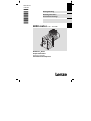
Montageanleitung
Mounting Instructions
Instructions de montage
8200 motec 0.25 ... 0.37 kW
E82MVxxx_2Bxxx
Frequenzumrichter
Frequency inverter
Convertisseur de fréquence
Lesen Sie zuerst diese Anleitung, bevor Sie mit den Arbeiten beginnen!
Beachten Sie die enthaltenen Sicherheitshinweise.
Ausführliche Informationen finden Sie in der Betriebsanleitung.
Read these instructions before you start working!
Follow the safety instructions given.
More detailed information can be found in the Operating Instructions.
Veuillez lire attentivement cette documentation avant toute action !
Les consignes de sécurité doivent impérativement être respectées.
Pour plus de détails, consulter les instructions de mise en service.
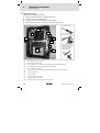
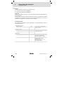
Typenschlüssel
E82MV xxx
−
x
B
xxx
xx
xx
Typ
Leistung
(z. B. 371 = 37 ´ 101 W = 0.37 kW)
(z. B. 751 = 75 ´ 101 W = 0.75 kW)
(z. B. 222 = 22 ´ 102 W = 2.2 kW)
(z. B. 752 = 75 ´ 102 W = 7.5 kW)
0.25 kW / 0.37 kW
Spannungsklasse
2 = 230 V
Geräte−Generation
Ausführung, Variante
001 = Standardausführung, verlackt
151 = Kühlkörper pulverbeschichtet
Hardwarestand
Softwarestand
Tipp!
Informationen und Hilfsmittel rund um die Lenze−Produkte finden Sie im
Download−Bereich unter
http://www.Lenze.com
EDK82MV371 DE/EN/FR 7.0
3
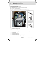
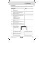
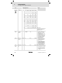
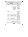
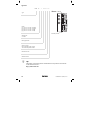
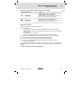
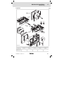
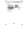
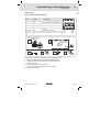
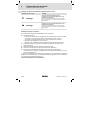
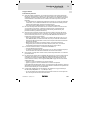
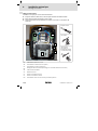
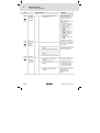
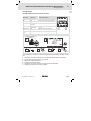
Inbetriebnahme 8200 motec ohne Funktionsmodul
l
Der 8200 motec ist nur funktionsfähig mit aufgesteckter FIF−Abdeckkappe ! (Auslieferungszustand).
– Ohne die FIF−Abdeckkappe ist der 8200 motec
gesperrt (Keypad: ).
Da der 8200 motec ohne Funktionsmodul keine
Steuerklemmen hat, kann das Starten und Stoppen
während des Betriebs auch über Netzschalten erfolgen.
Die Funktion speichert bei Netzschalten oder
Betriebsunterbrechungen den Sollwert zum Zeitpunkt der Unterbrechung. Nach Netzwiederkehr
läuft der Antrieb selbsttätig wieder an!
Wenn der Antrieb in Schritt nicht anläuft (
erlischt nicht), drücken, um den 8200 motec
freizugeben.
l
l
l
E82ZWLxxx
A
8200mot041
L1 / L2 / L3 / N / PE
E82ZBB
a e b c d
8 SP h i k f g j
m
888 8888porn q
88888
iH
oL
d c
j
0140
5000
z
w x
y
vt
s u
tv
2
1
z
x w
y
AIF
2V 2 U 2 W
1 W 1V 1 U
EP
w
3
Hz
u s
m
A V zH
C°Ω hs %
mpr
j
z 0....+50 Hz
y 0....- 50 Hz
8200mot042
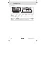
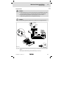
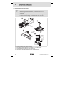
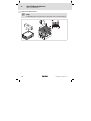
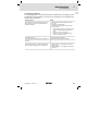
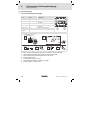
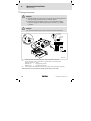
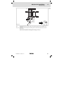
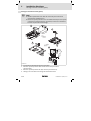
Schritt
Bemerkung
Handterminal und Verbindungsleitung sind nicht im Lieferumfang
enthalten.
Handterminal (enthält Keypad) mit motec verbinden.
Stecker der Verbindungsleitung in die AIF−Schnittstelle
am motec stecken.
Netzspannung zuschalten.
Der Antriebsregler ist nach ca. 1 Sekunde betriebsbereit.
Keypad: Sollwert über die Funktion
aktivieren
Selbstanlauf möglich!
vorgeben.
Rechtslauf
Linkslauf
erlischt. Der Antrieb läuft jetzt.
Display zeigt Ausgangsfrequenz.
Störungen während der Inbetriebnahme oder während des Betriebs? Kapitel 8
0Abb. 0Tab. 0
4
EDK82MV371 DE/EN/FR 7.0
Inhalt
i
1 Über diese Dokumentation . . . . . . . . . . . . . . . . . . . . . . . . . . . . . . . . . . . . . . . . . . .
Verwendete Konventionen . . . . . . . . . . . . . . . . . . . . . . . . . . . . . . . . . . . . . . . . . . .
Verwendete Hinweise . . . . . . . . . . . . . . . . . . . . . . . . . . . . . . . . . . . . . . . . . . . . . . .
Bestimmungsgemäße Verwendung . . . . . . . . . . . . . . . . . . . . . . . . . . . . . . . . . . .
6
6
7
8
2 Sicherheitshinweise . . . . . . . . . . . . . . . . . . . . . . . . . . . . . . . . . . . . . . . . . . . . . . . .
Allgemeine Sicherheitshinweise . . . . . . . . . . . . . . . . . . . . . . . . . . . . . . . . . . . . . .
Allgemeine Sicherheits− und Anwendungshinweise für Lenze−Motoren . . . . . .
Restgefahren . . . . . . . . . . . . . . . . . . . . . . . . . . . . . . . . . . . . . . . . . . . . . . . . . . . . . .
9
9
13
16
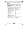
3 Technische Daten . . . . . . . . . . . . . . . . . . . . . . . . . . . . . . . . . . . . . . . . . . . . . . . . . .
Allgemeine Daten und Einsatzbedingungen . . . . . . . . . . . . . . . . . . . . . . . . . . .
Betrieb mit Bemessungsleistung (Normalbetrieb) . . . . . . . . . . . . . . . . . . . . . . . .
Abmessungen . . . . . . . . . . . . . . . . . . . . . . . . . . . . . . . . . . . . . . . . . . . . . . . . . . . . .
Mechanische Ausführung . . . . . . . . . . . . . . . . . . . . . . . . . . . . . . . . . . . . . . . . . . . .
18
18
21
22
22
4 Mechanische Installation . . . . . . . . . . . . . . . . . . . . . . . . . . . . . . . . . . . . . . . . . . . .
motec mit Motor oder Getriebemotor . . . . . . . . . . . . . . . . . . . . . . . . . . . . . . . . . .
Wandmontage . . . . . . . . . . . . . . . . . . . . . . . . . . . . . . . . . . . . . . . . . . . . . . . . . . . . .
Motormontage . . . . . . . . . . . . . . . . . . . . . . . . . . . . . . . . . . . . . . . . . . . . . . . . . . . .
23
23
26
31
5 Elektrische Installation . . . . . . . . . . . . . . . . . . . . . . . . . . . . . . . . . . . . . . . . . . . . . .
Netzanschluss . . . . . . . . . . . . . . . . . . . . . . . . . . . . . . . . . . . . . . . . . . . . . . . . . . . .
Sicherungen und Leitungsquerschnitte . . . . . . . . . . . . . . . . . . . . . . . . . . . . . . . . .
Dimensionierung von Netzschützen . . . . . . . . . . . . . . . . . . . . . . . . . . . . . . . . . . .
Montage Funktionsmodul (Option) . . . . . . . . . . . . . . . . . . . . . . . . . . . . . . . . . . . .
35
35
36
36
38
6 Abschließende Arbeiten . . . . . . . . . . . . . . . . . . . . . . . . . . . . . . . . . . . . . . . . . . . . .
motec zusammenbauen . . . . . . . . . . . . . . . . . . . . . . . . . . . . . . . . . . . . . . . . . . . . .
39
39
7 Inbetriebnahme . . . . . . . . . . . . . . . . . . . . . . . . . . . . . . . . . . . . . . . . . . . . . . . . . . . .
Vor dem ersten Einschalten . . . . . . . . . . . . . . . . . . . . . . . . . . . . . . . . . . . . . . . . . .
Betriebsart wählen . . . . . . . . . . . . . . . . . . . . . . . . . . . . . . . . . . . . . . . . . . . . . . . . .
Parametrierung mit dem Handterminal E82ZBB . . . . . . . . . . . . . . . . . . . . . . . . .
U/f−Kennliniensteuerung . . . . . . . . . . . . . . . . . . . . . . . . . . . . . . . . . . . . . . . . . . . .
Vector−Regelung . . . . . . . . . . . . . . . . . . . . . . . . . . . . . . . . . . . . . . . . . . . . . . . . . . .
Wichtige Antriebsregler−Codestellen . . . . . . . . . . . . . . . . . . . . . . . . . . . . . . . . . . .
41
41
42
44
45
47
50
8 Fehlersuche und Störungsbeseitigung . . . . . . . . . . . . . . . . . . . . . . . . . . . . . . . . .
Fehlersuche . . . . . . . . . . . . . . . . . . . . . . . . . . . . . . . . . . . . . . . . . . . . . . . . . . . . . . .
Störungsmeldungen . . . . . . . . . . . . . . . . . . . . . . . . . . . . . . . . . . . . . . . . . . . . . . . .
LED’s am Antriebsregler (Statusanzeige) . . . . . . . . . . . . . . . . . . . . . . . . . . . . . . . .
62
62
64
64
EDK82MV371 DE/EN/FR 7.0
5
1
Über diese Dokumentation
Verwendete Konventionen
1
Über diese Dokumentation
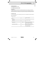
Informationen zur Gültigkeit
Diese Anleitung ist gültig für
ƒ Frequenzumrichter E82MV251
ƒ Frequenzumrichter E82MV371
Zielgruppe
Diese Dokumentation richtet sich an qualifiziertes Fachpersonal nach IEC 60364.
Qualifiziertes Fachpersonal sind Personen, die für die auszuführenden Tätigkeiten bei der
Aufstellung, Montage, Inbetriebsetzung und dem Betrieb des Produkts über entsprechende Qualifikationen verfügen.
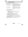
Verwendete Konventionen
Diese Dokumentation verwendet folgende Konventionen zur Unterscheidung verschiedener Arten von Information:
Zahlenschreibweise
Dezimaltrennzeichen
Punkt
Es wird generell der Dezimalpunkt verwendet.
Zum Beispiel: 1234.56
Warnhinweise
UL−Warnhinweise
UR−Warnhinweise
Werden nur in der englischen Sprache
verwendet.
Symbole
6
Seitenverweis
Verweis auf eine andere Seite mit zusätzlichen Informationen
Zum Beispiel: 16 = siehe Seite 16
Dokumentationsverweis
Verweis auf eine andere Dokumentation mit zusätzlichen Informationen
Zum Beispiel: EDKxxx = siehe
Dokumentation EDKxxx
EDK82MV371 DE/EN/FR 7.0
Über diese Dokumentation
1
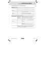
Verwendete Hinweise
Verwendete Hinweise
Um auf Gefahren und wichtige Informationen hinzuweisen, werden in dieser Dokumentation folgende Piktogramme und Signalwörter verwendet:
Sicherheitshinweise
Aufbau der Sicherheitshinweise:
Gefahr!
(kennzeichnet die Art und die Schwere der Gefahr)
Hinweistext
(beschreibt die Gefahr und gibt Hinweise, wie sie vermieden werden kann)
Piktogramm und Signalwort
Bedeutung
Gefahr!
Gefahr von Personenschäden durch gefährliche elektrische
Spannung
Hinweis auf eine unmittelbar drohende Gefahr, die den Tod
oder schwere Verletzungen zur Folge haben kann, wenn
nicht die entsprechenden Maßnahmen getroffen werden.
Gefahr!
Gefahr von Personenschäden durch eine allgemeine Gefahrenquelle
Hinweis auf eine unmittelbar drohende Gefahr, die den Tod
oder schwere Verletzungen zur Folge haben kann, wenn
nicht die entsprechenden Maßnahmen getroffen werden.
Stop!
Gefahr von Sachschäden
Hinweis auf eine mögliche Gefahr, die Sachschäden zur
Folge haben kann, wenn nicht die entsprechenden Maßnahmen getroffen werden.
Anwendungshinweise
Piktogramm und Signalwort
Bedeutung
Hinweis!
Wichtiger Hinweis für die störungsfreie Funktion
Tipp!
Nützlicher Tipp für die einfache Handhabung
EDK82MV371 DE/EN/FR 7.0
Verweis auf andere Dokumentation
7
1
Über diese Dokumentation
Bestimmungsgemäße Verwendung
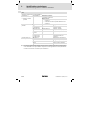
Spezielle Sicherheitshinweise und Anwendungshinweise für UL und UR
Piktogramm und Signalwort
Bedeutung
Warnings!
Sicherheitshinweis oder Anwendungshinweis für den Betrieb eines UL−approbierten Geräts in UL−approbierten Anlagen.
Möglicherweise wird das Antriebssystem nicht UL−gerecht
betrieben, wenn nicht die entsprechenden Maßnahmen
getroffen werden.
Warnings!
Sicherheitshinweis oder Anwendungshinweis für den Betrieb eines UR−approbierten Geräts in UL−approbierten Anlagen.
Möglicherweise wird das Antriebssystem nicht UL−gerecht
betrieben, wenn nicht die entsprechenden Maßnahmen
getroffen werden.
Bestimmungsgemäße Verwendung
Frequenzumrichter 8200 motec und Zubehör
ƒ sind Komponenten
– zur Steuerung und Regelung von drehzahlveränderbaren Antrieben mit
Asynchron−Normmotoren, Reluktanzmotoren, PM−Synchronmotoren mit
asynchronem Dämpferkäfig.
– zum Einbau in eine Maschine.
– zum Zusammenbau mit anderen Komponenten zu einer Maschine.
ƒ dürfen nur unter den in dieser Dokumentation vorgeschriebenen
Einsatzbedingungen betrieben werden.
ƒ erfüllen die Schutzanforderungen der EG−Richtlinie "Niederspannung".
ƒ sind keine Maschinen im Sinne der EG−Richtlinie "Maschinen".
ƒ sind keine Haushaltsgeräte, sondern als Komponenten ausschließlich für die
Weiterverwendung zur gewerblichen Nutzung bzw. professionellen Nutzung im
Sinne der EN 61000−3−2 bestimmt.
Das Antriebssystem (Frequenzumrichter und Antrieb) entspricht der EG−Richtlinie "Elektromagnetische Verträglichkeit", wenn es nach den Vorgaben des CE−typischen Antriebssystems installiert wird.
Eine andere oder darüberhinausgehende Verwendung gilt als sachwidrig!
8
EDK82MV371 DE/EN/FR 7.0
Sicherheitshinweise
2
Allgemeine Sicherheitshinweise
2
Sicherheitshinweise
Allgemeine Sicherheitshinweise
Geltungsbereich
Die folgenden Sicherheitshinweise gelten allgemein für Lenze−Antriebs−und Automatisierungskomponenten.
Beachten Sie unbedingt die produktspezifischen Sicherheits− und Anwendungshinweise
in dieser Dokumentation!
Hinweise für den Einsatz der Antriebsregler in UL−approbierten Anlagen finden Sie in der
separaten beiliegenden Dokumentation.
Auch zu Ihrer eigenen Sicherheit
Gefahr!
Wenn Sie die folgenden grundlegenden Sicherheitsmaßnahmen missachten,
kann dies zu schweren Personenschäden und Sachschäden führen:
ƒ Lenze−Antriebs− und Automatisierungskomponenten ...
... ausschließlich bestimmungsgemäß verwenden.
... niemals trotz erkennbarer Schäden in Betrieb nehmen.
... niemals technisch verändern.
... niemals unvollständig montiert in Betrieb nehmen.
... niemals ohne erforderliche Abdeckungen betreiben.
... können während und nach dem Betrieb − ihrer Schutzart entsprechend − spannungsführende, auch bewegliche oder rotierende Teile haben. Oberflächen können heiß
sein.
ƒ
Alle Vorgaben der beiliegenden und zugehörigen Dokumentation beachten.
Dies ist Voraussetzung für einen sicheren und störungsfreien Betrieb sowie für das
Erreichen der angegebenen Produkteigenschaften.
Die in diesem Dokument dargestellten verfahrenstechnischen Hinweise und Schaltungsausschnitte sind Vorschläge, deren Übertragbarkeit auf die jeweilige Anwendung überprüft werden muss. Für die Eignung der angegebenen Verfahren und Schaltungsvorschläge übernimmt der Hersteller keine Gewähr.
ƒ Alle Arbeiten mit und an Lenze−Antriebs− und Automatisierungskomponenten darf
nur qualifiziertes Fachpersonal ausführen.
Nach IEC 60364 bzw. CENELEC HD 384 sind dies Personen, ...
... die mit Aufstellung, Montage, Inbetriebsetzung und Betrieb des Produkts vertraut
sind.
... die über die entsprechenden Qualifikationen für ihre Tätigkeit verfügen.
... die alle am Einsatzort geltenden Unfallverhütungsvorschriften, Richtlinien und Gesetze kennen und anwenden können.
EDK82MV371 DE/EN/FR 7.0
9
2
Sicherheitshinweise
Allgemeine Sicherheitshinweise
Transport, Lagerung
ƒ Transport und Lagerung in trockener, schwingungsarmer Umgebung ohne
aggressiver Atmosphäre; möglichst in der Hersteller−Verpackung.
– Vor Staub und Stößen schützen.
– Klimatische Bedingungen gemäß den Technischen Daten einhalten.
Mechanische Installation
ƒ Das Produkt nach den Vorschriften der zugehörigen Dokumentation aufstellen.
Beachten Sie insbesondere den Abschnitt "Einsatzbedingungen" im Kapitel
"Technische Daten".
ƒ Sorgen Sie für sorgfältige Handhabung und vermeiden Sie mechanische
Überlastung. Verbiegen Sie bei der Handhabung weder Bauelemente noch ändern
Sie Isolationsabstände.
ƒ Das Produkt enthält elektrostatisch gefährdete Bauelemente, die durch Kurzschluss
oder statische Entladungen (ESD) leicht beschädigt werden können. Berühren Sie
deshalb elektronische Bauelemente und Kontakte nur, wenn Sie zuvor
ESD−Maßnahmen getroffen haben.
Elektrische Installation
ƒ Führen Sie die elektrische Installation nach den einschlägigen Vorschriften durch
(z. B. Leitungsquerschnitte, Absicherungen, Schutzleiteranbindung). Zusätzliche
Hinweise enthält die Dokumentation.
ƒ Beachten Sie bei Arbeiten an unter Spannung stehenden Produkten die geltenden
nationalen Unfallverhütungsvorschriften (z. B. BGV 3).
ƒ
Die Dokumentation enthält Hinweise für die EMV−gerechte Installation
(Schirmung, Erdung, Anordnung von Filtern und Verlegung der Leitungen). Der
Hersteller der Anlage oder Maschine ist verantwortlich für die Einhaltung der im
Zusammenhang mit der EMV−Gesetzgebung geforderten Grenzwerte.
Warnung: Die Antriebsregler sind Produkte, die nach EN 61800−3 in Antriebssystemen der Kategorie C2 eingesetzt werden können. Diese Produkte können in öffentlichen Netzen Funkstörungen verursachen. In diesem Fall kann es für den Betreiber
erforderlich sein, entsprechende Maßnahmen durchzuführen.
ƒ Alle steckbaren Anschlussklemmen nur im spannungslosen Zustand aufstecken
oder abziehen!
Inbetriebnahme
ƒ Sie müssen die Anlage ggf. mit zusätzlichen Überwachungs− und
Schutzeinrichtungen gemäß den jeweils gültigen Sicherheitsbestimmungen
ausrüsten (z. B. Gesetz über technische Arbeitsmittel,
Unfallverhütungsvorschriften).
10
EDK82MV371 DE/EN/FR 7.0
Sicherheitshinweise
2
Allgemeine Sicherheitshinweise
ƒ Vor der Inbetriebnahme Transportsicherungen entfernen und für spätere
Transporte aufbewahren.
Betrieb
ƒ Halten Sie während des Betriebs alle Schutzabdeckungen und Türen geschlossen.
Wartung und Instandhaltung
ƒ Die Komponenten sind wartungsfrei, wenn die vorgeschriebenen
Einsatzbedingungen eingehalten werden.
ƒ Bei verunreinigter Umgebungsluft können Kühlflächen verschmutzen oder
Kühlöffnungen verstopft werden. Bei diesen Betriebsbedingungen deshalb
regelmäßig die Kühlflächen und Kühlöffnungen reinigen. Dazu niemals scharfe
oder spitze Gegenstände verwenden!
ƒ Nachdem das System von der Versorgungsspannung getrennt ist, dürfen Sie
spannungsführende Geräteteile und Leistungsanschlüsse nicht sofort berühren,
weil Kondensatoren aufgeladen sein können. Beachten Sie dazu die
entsprechenden Hinweisschilder auf dem Gerät.
Entsorgung
ƒ Metalle und Kunststoffe zur Wiederverwertung geben. Bestückte Leiterplatten
fachgerecht entsorgen.
Warnings!
ƒ The device has no overspeed protection.
ƒ Must be provided with external or remote overload protection.
ƒ Suitable for use on a circuit capable of delivering not more than 5000
rms symmetrical amperes, 240 V maximum (240 V devices) or 500 V
maximum (400/500 V devices) resp.
ƒ Circuit breakers (either inverse−time or instantaneous trip types) may
be used in lieu of above fuses when it is shown that the let−through
energy (I2t) and peak let−through current (Ip) of the inverse−time
current−limiting circuit breaker will be less than that of the
non−semiconductor type K5 fuses with which the drive has been
tested. An inverse−time circuit breaker may be used, sized upon the
input rating of the drive, multiplied by 300 %.
ƒ Use 60/75 °C or 75 °C copper wire only.
ƒ If mounted on a motor the environmental rating tests for Type 4 and
Type 12 shall be performed.
EDK82MV371 DE/EN/FR 7.0
11
2
Sicherheitshinweise
Allgemeine Sicherheitshinweise
Warnings!
ƒ Protection du moteur contre les surcharges
– Pour obtenir des informations sur le niveau de protection offert par la
–
ƒ
–
–
ƒ
protection intégrée contre les surcharges du moteur, se reporter aux
manuels correspondants ou aux systèmes d’aide logiciels.
Si la protection statique intégrée contre les surcharges du moteur n’est
pas utilisée, prévoir impérativement un dispositif de protection
externe ou séparé contre les surcharges.
Protection par disjoncteur
La protection statique intégrée n’offre pas la même protection qu’un
disjoncteur.
Une protection par disjoncteur externe doit être fournie,
conformément aux indications du fabricant, au National Electrical
Code et aux autres dispositions applicables.
En cas de montage sur le moteur, il convient de procéder à des
évaluations environnementales pour les types 4 et 12.
ƒ Fusibles/disjoncteurs
– Se reporter à ce manuel pour connaître le dimensionnement maximal
des fusibles/disjoncteurs et les types
de disjoncteur à utiliser.
– La tension des fusibles doit être adaptée à la tension d’entrée
(exigence minimale).
12
EDK82MV371 DE/EN/FR 7.0
Sicherheitshinweise
2
Allgemeine Sicherheits− und Anwendungshinweise für Lenze−Motoren
Allgemeine Sicherheits− und Anwendungshinweise für Lenze−Motoren
(gemäß Niederspannungsrichtlinie 2006/95/EG)
Allgemein
Niederspannungsmaschinen haben gefährliche, spannungsführende und rotierende
Teile sowie möglicherweise heiße Oberflächen.
Bei Synchronmaschinen werden bei drehender Maschine auch an den offenen Klemmen
Spannungen induziert.
Alle Arbeiten zu Transport, Anschluss, Inbetriebnahme und Instandhaltung darf nur qualifiziertes, verantwortliches Fachpersonal ausführen (EN 50110−1 (VDE 0105−1) und
IEC 60364 beachten). Unsachgemäßes Verhalten kann schwere Personen− und Sachschäden verursachen.
Niederspannungsmaschinen nur unter den Einsatzzwecken betreiben, die im Abschnitt
"Bestimmungsgemäße Verwendung" angegeben sind.
Die Bedingungen am Einsatzort müssen allen Angaben entsprechen, die auf dem Leistungsschild und in der Dokumentation genannt sind.
Bestimmungsgemäße Verwendung
Niederspannungsmaschinen sind für gewerbliche Anlagen bestimmt. Sie entsprechen
den harmonisierten Normen der Reihe IEC/EN60034 (VDE 0530). Der Einsatz im Ex−Bereich ist verboten, sofern nicht ausdrücklich hierfür vorgesehen (Zusatzhinweise beachten).
Niederspannungsmaschinen sind Komponenten zum Einbau in Maschinen im Sinne der
Maschinenrichtlinie 2006/42/EG. Die Inbetriebnahme ist solange untersagt, bis die Konformität des Endprodukts mit dieser Richtlinie festgestellt ist (u. a. EN 60204−1 beachten).
Niederspannungsmaschinen in Schutzart IP23 oder geringer nicht ohne besondere
Schutzmaßnahmen im Freien verwenden.
Die eingebauten Bremsen nicht als Sicherheitsbremsen verwenden. Es ist nicht auszuschließen, dass durch nicht zu beeinflussende Störfaktoren, z. B. Öleintritt durch Versagen
des A−seitigen Wellendichtrings, das Brems−Drehmoment reduziert sein kann.
Transport, Einlagerung
Nach der Auslieferung festgestellte Beschädigungen dem Transportunternehmen sofort
mitteilen; die Inbetriebnahme ist ggf. auszuschließen. Eingeschraubte Transportösen fest
anziehen. Sie sind für das Gewicht der Niederspannungsmaschine ausgelegt, keine zusätzlichen Lasten anbringen. Wenn notwendig, ausreichend bemessene Transportmittel
(z. B. Seilführungen) verwenden.
Vorhandene Transportsicherungen vor Inbetriebnahme entfernen. Für weitere Transporte erneut verwenden. Werden Niederspannungsmaschinen eingelagert, auf eine trockene, staubfreie und schwingungsarme (veff £ 0.2 mm/s) Umgebung achten (Lagerstillstandsschäden).
EDK82MV371 DE/EN/FR 7.0
13
2
Sicherheitshinweise
Allgemeine Sicherheits− und Anwendungshinweise für Lenze−Motoren
Aufstellung
Auf plane Auflage, gute Fuß− bzw. Flanschbefestigung und genaue Ausrichtung bei direkter Kupplung achten. Aufbaubedingte Resonanzen mit der Drehfrequenz und der doppelten Speisefrequenz vermeiden. Läufer von Hand drehen, auf ungewöhnliche Schleifgeräusche achten. Drehrichtung im ungekuppelten Zustand kontrollieren (Abschnitt
"Elektrischer Anschluss" beachten).
Riemenscheiben und Kupplungen nur mit geeigneten Vorrichtungen aufziehen oder abziehen. Zur leichteren Handhabung vorher erwärmen. Riemenscheiben und Kupplungen
mit einem Berührschutz abdecken. Unzulässige Riemenspannungen vermeiden.
Die Maschinen sind mit halber Passfeder gewuchtet. Die Kupplung muss ebenfalls mit
halber Passfeder gewuchtet sein. Überstehenden, sichtbaren Passfederanteil abarbeiten.
Eventuell erforderliche Rohranschlüsse herstellen. Bauformen mit Wellenende nach unten bauseits mit einer Abdeckung ausrüsten, die verhindert, dass Fremdkörper in den Lüfter hineinfallen. Die Belüftung darf nicht behindert werden und die Abluft − auch benachbarter Aggregate − nicht unmittelbar wieder angesaugt werden.
Elektrischer Anschluss
Alle Arbeiten dürfen nur von qualifiziertem Fachpersonal an der stillstehenden Niederspannungsmaschine im freigeschalteten und gegen Wiedereinschalten gesicherten Zustand vorgenommen werden. Das gilt auch für Hilfsstromkreise (z. B. Bremse, Geber,
Fremdlüfter).
Spannungsfreiheit prüfen!
Überschreiten der Toleranzen in IEC/EN 60034−1 (VDE 0530−1) − Spannung ±5 %, Frequenz ±2 %, Kurvenform, Symmetrie − erhöht die Erwärmung und beeinflusst die elektromagnetische Verträglichkeit.
Schaltungshinweise, Angaben auf dem Leistungsschild und Anschlussschema im Klemmenkasten beachten.
Der Anschluss muss so erfolgen, dass eine dauerhaft sichere, elektrische Verbindung aufrecht erhalten wird (keine abstehenden Drahtenden); zugeordnete Kabelendbestückung
verwenden. Sichere Schutzleiterverbindung herstellen. Steckverbinder bis zum Anschlag
festschrauben.
Die kleinsten Luftabstände zwischen blanken, spannungsführenden Teilen und gegen
Erde dürfen folgende Werte nicht unterschreiten: 8 mm bei UN £ 550 V, 10 mm bei
UN £ 725 V, 14 mm bei UN £ 1000 V.
Der Klemmenkasten muss frei sein von Fremdkörpern, Schmutz und Feuchtigkeit. Nicht
benötigte Kabeleinführungsöffnungen und den Klemmenkasten staubdicht und wasserdicht verschließen.
14
EDK82MV371 DE/EN/FR 7.0
Sicherheitshinweise
2
Allgemeine Sicherheits− und Anwendungshinweise für Lenze−Motoren
Inbetriebnahme und Betrieb
Vor Inbetriebnahme nach längerer Lagerzeit den Isolationswiderstand messen. Bei Werten £ 1 kW je Volt Bemessungsspannung die Wicklung trocknen.
Für den Probebetrieb ohne Abtriebselemente die Passfeder sichern. Schutzeinrichtungen
auch im Probebetrieb nicht außer Funktion setzen.
Bei Niederspannungsmaschinen mit Bremse vor der Inbetriebnahme die einwandfreie
Funktion der Bremse prüfen.
Eingebaute Temperaturfühler sind kein Vollschutz der Maschine, ggf. Maximalstrom begrenzen. Antriebsregler so parametrieren, dass nach einigen Sekunden Betrieb mit I > IN
der Motor abgeschaltet wird, insbesondere bei Gefahr des Blockierens.
Schwingstärken veff £ 3.5 mm/s (PN £ 15 kW) bzw. 4.5 mm/s (PN > 15 kW) sind in gekuppeltem Betrieb unbedenklich.
Bei Veränderungen gegenüber dem Normalbetrieb, z. B. erhöhte Temperaturen, Geräusche, Schwingungen, die Ursache ermitteln, ggf. Rücksprache mit dem Hersteller. Im
Zweifelsfall Niederspannungsmaschine abschalten.
Bei starkem Schmutzanfall Luftwege regelmäßig reinigen.
Wellendichtringe und Wälzlager haben eine begrenzte Lebensdauer.
Lagerungen mit Nachschmiereinrichtung bei laufender Niederspannungsmaschine nachfetten. Nur vom Hersteller freigegebene Fette verwenden. Wenn Fettaustrittsbohrungen
mit Stopfen verschlossen sind (IP54 Abtriebsseite; IP23 Abtriebs−und Nichtabtriebsseite),
vor Inbetriebnahme Stopfen entfernen. Bohrungen mit Fett verschließen. Lagerwechsel
bei Dauerschmierung (2Z−Lager) nach ca. 10.000 h − 20.000 h, spätestens jedoch nach
3 − 4 Jahren.
Beachten Sie die produktspezifischen Sicherheits− und Anwendungshinweise in dieser
Anleitung!
EDK82MV371 DE/EN/FR 7.0
15
2
Sicherheitshinweise
Restgefahren
Restgefahren
Personenschutz
ƒ Lenze−Antriebsregler (Frequenzumrichter, Servo−Umrichter, Stromrichter) und
zugehörige Komponenten können während des Betriebs − ihrer Schutzart
entsprechend − spannungsführende, auch bewegliche oder rotierende Teile haben.
Oberflächen können heiß sein.
– Bei unzulässigem Entfernen der erforderlichen Abdeckung, bei unsachgemäßem
Einsatz, bei falscher Installation oder Bedienung besteht die Gefahr von schweren
Personen− oder Sachschäden.
– Weitere Informationen entnehmen Sie der Dokumentation.
ƒ Im Antriebsregler treten hohe Energien auf. Deshalb bei Arbeiten am Antriebsregler
unter Spannung immer eine persönliche Schutzausrüstung tragen (Körperschutz,
Kopfschutz, Augenschutz, Gehörschutz, Handschutz).
ƒ Schalten Sie vor Arbeitsbeginn / Öffnen des Gerätes den Antriebsregler
spannungslos und warten Sie mindestens 1 Minute, da nach dem Netzabschalten
die Leistungsklemmen U, V, W, BR0, BR1, BR2 und die Pins der Schnittstelle FIF
gefährliche Spannung führen.
– Überprüfen Sie nach dem Öffnen des motec, ob die Leistungsklemmen L1, L2 bzw.
(L2/N), L3, U, V, W, BR0, BR1, BR2, die Relaisausgänge K11, K12, K14 bzw. der
elektronische Schaltausgang K12 (Option, abhängig von Geräteausführung) und
die Pins der Schnittstelle FIF spannungslos sind.
– Auch bei vom Netz getrenntem Antriebsregler können die Relaisausgänge K11,
K12, K14 bzw. der elektronische Schaltausgang K12 (Option, abhängig von
Geräteausführung) gefährliche Spannung führen!
ƒ Der Ableitstrom gegen PE−Potenzial ist > 3.5 mA. Nach EN 61800−5−1
– ist eine Festinstallation erforderlich.
– muss der PE−Leiter doppelt ausgeführt sein oder einfach ausgeführt einen
Leitungsquerschnitt von mindestens 10 mm2 haben.
ƒ Sicherheitstechnische Trennung des Antriebsreglers vom Netz nur über ein
eingangsseitiges Schütz durchführen.
ƒ Antriebsregler können einen Gleichstrom im Schutzleiter verursachen. Wird für den
Schutz bei einer direkten oder indirekten Berührung ein Differenzstromgerät (RCD)
oder ein Fehlerstrom−Überwachungsgerät (RCM) verwendet, ist auf der
Stromversorgungsseite nur ein RCD/RCM folgenden Typs zulässig:
– Typ B bei Anschluss an ein 3−phasiges Netz
– Typ A oder Typ B bei Anschluss an ein 1−phasiges Netz
Alternativ kann eine andere Schutzmaßnahme angewendet werden, wie z. B. Trennung von der Umgebung durch doppelte oder verstärkte Isolierung oder Trennung
vom Versorgungsnetz durch einen Transformator.
ƒ Wenn Sie die Funktion Drehrichtungsvorgabe" über das digitale Signal
DCTRL1−CW/CCW verwenden (C0007 = 0 ... 13, C0410/3 ¹ 255):
– Bei Drahtbruch oder bei Ausfall der Steuerspannung kann der Antrieb die
Drehrichtung wechseln.
16
EDK82MV371 DE/EN/FR 7.0
Sicherheitshinweise
2
Restgefahren
ƒ Wenn Sie die Funktion "Fangschaltung" (C0142 = 2, 3) bei Maschinen mit geringem
Massenträgheitsmoment und geringer Reibung verwenden:
– Nach Reglerfreigabe im Stillstand kann der Motor kurzzeitig anlaufen oder
kurzzeitig die Drehrichtung wechseln.
ƒ Der Kühlkörper des motec hat eine Betriebstemperatur > 60 °C:
– Hautkontakt mit dem Kühlkörper führt zu Verbrennungen.
Geräteschutz
ƒ Häufiges Schalten der Versorgungsspannung (z. B. Tipp−Betrieb über Netzschütz)
kann die Eingangsstrombegrenzung des Antriebsreglers überlasten und zerstören:
– Zwischen zwei Einschaltvorgängen mindestens 3 Minuten warten.
ƒ Schütze in der Motorleitung nur bei gesperrtem Regler schalten. Andernfalls ...
– können Überwachungsfunktionen des Antriebsreglers ansprechen.
– kann der Antriebsregler unter ungünstigen Betriebsbedingungen zerstört
werden.
Motorschutz
ƒ Bei bestimmten Einstellungen am Antriebsregler kann der angeschlossene Motor
überhitzt werden (z. B. bei längerem Betrieb der Gleichstrombremse oder eines
eigenbelüfteten Motors bei kleiner Drehzahl).
– Weitgehenden Schutz gegen Überlastung bietet der Einsatz eines
Überstromrelais oder einer Temperaturüberwachung.
– Wir empfehlen zur Temperaturüberwachung des Motors, PTC (Kaltleiter) oder
Thermokontakte einzusetzen. (Lenze−Drehstrommotoren sind standardmäßig mit
Thermokontakten (Öffner) bestückt)
– PTC oder Thermokontakte können am Antriebsregler angeschlossen werden.
Schutz der Maschine/Anlage
ƒ Antriebe können gefährliche Überdrehzahlen erreichen (z. B. Einstellung hoher
Ausgangsfrequenzen bei dafür ungeeigneten Motoren und Maschinen).
– Die Antriebsregler bieten keinen Schutz gegen solche Betriebsbedingungen.
Setzen Sie dafür zusätzliche Komponenten ein.
EDK82MV371 DE/EN/FR 7.0
17
3
Technische Daten
Allgemeine Daten und Einsatzbedingungen
3
Technische Daten
Allgemeine Daten und Einsatzbedingungen
Konformität und Approbation
Konformität
CE
2006/95/EG
Niederspannungsrichtlinie
2004/108/EG
EMV−Richtlinie
UL 508C
Underwriter Laboratories (File No. E132659)
Power Conversion Equipment
Approbation
UL
CSA
22.2 No. 14
GOST−R
51321.1−2000 No. POCC DE.AN30.Bo8845
51321.3−99
Personenschutz und Geräteschutz
Schutzart
IEC/EN60529
NEMA 250 / UL50
IP55 ohne Schutzkappe auf der AIF−Schnittstelle,
Berührschutz nach Typ 12
IEC/EN60529
NEMA 250 / UL50
IP65 mit Schutzkappe auf der AIF−Schnittstelle,
Berührschutz nach Typ 4
Erdableitstrom
IEC/EN 61800−5−1
> 3.5 mA AC
> 10 mA DC
Isolierung von Steuerschaltkreisen
IEC/EN 61800−5−1
Sichere Trennung vom Netz durch doppelte (verstärkte)
Isolierung
Isolationsfestigkeit
IEC/EN 61800−5−1
Überspannungskategorie III für Aufstellhöhe £ 2000 m
Schutzmaßnahmen
Gegen Kurzschluss, Erdschluss (erdschlussfest im Betrieb, eingeschränkt erdschlussfest beim Netzeinschalten) Überspannung, Kippen des Motors, Motor−
Übertemperatur (Eingang für PTC oder Thermokontakt, I2t−Überwachung)
Bestimmungen und Sicherheitshinweise beachten!
Überspannungskategorie II für Aufstellhöhe > 2000 m
18
EDK82MV371 DE/EN/FR 7.0
Technische Daten
3
Allgemeine Daten und Einsatzbedingungen
EMV
Einhaltung der Anforderungen nach EN 61800−3
Störaussendung
l leitungsgeführt
IEC/EN 61800−3
Motormontage:
Einhaltung der Grenzwertklasse C1
Wandmontage:
– Einhaltung der Grenzwertklasse C1 bei Verwendung geschirmter Motorleitungen bis 1 m Länge
– Einhaltung der Grenzwertklasse C2 bei Verwendung geschirmter Motorleitungen bis 10 m Länge
Störfestigkeit
Betrieb an öffentlichen
Netzen
1)
Anforderungen
Norm
Schärfegrad
ESD
IEC/EN 61000−4−2
8 kV bei Luftentladung,
4 kV bei Kontaktentladung
leitungsgeführte
Hochfrequenz
IEC/EN 61000−4−6
150 kHz ... 80 MHz,
10 V/m 80 % AM (1 kHZ)
Burst
IEC/EN 61000−4−4
3/4, d. h. 2 kV / 5 kHz
Surge (Stoßspannung auf Netzleitung)
IEC/EN 61000−4−5
3, d. h. 1.2 / 50 ms,
1 kV Phase−Phase, 2 kV Phase−PE
EN 61000−3−2
Begrenzung von Oberschwingungsströmen
Gesamtleistung am Netz
Einhaltung der Anforderungen 1)
0.25 kW ... 0.75 kW
mit Netzdrossel
>1 kW
keine Maßnahmen erforderlich
Die genannten Zusatzmaßnahmen bewirken, dass alleinig die Antriebsregler die Anforderungen der
EN 61000−3−2 erfüllen. Die Einhaltung der Anforderungen für die Maschine/Anlage liegt in der
Verantwortung des Maschinen−/Anlagenherstellers!
EDK82MV371 DE/EN/FR 7.0
19
3
Technische Daten
Allgemeine Daten und Einsatzbedingungen
Umgebungsbedingungen
Klimatisch
Lagerung
IEC/EN 60721−3−1
1K3 (−25 ... +60 °C)
Transport
IEC/EN 60721−3−2
2K3 (−25 ... +70 °C)
IEC/EN 60721−3−3
3K3 (−20 ... +60 °C)
> +40 °C den Ausgangs−Bemessungsstrom um 2,5 %/°C
reduzieren.
Betrieb
Aufstellhöhe
< 4000 m üNN
> 1000 m üNN den Ausgangs−Bemessungsstrom um
5 %/ 1000 m reduzieren.
Elektrisch
Netzanschluss AC−Netz
Max. Netzspannungsbereich
E82MV251... und E82MV371...
1/N/PE bzw. 2/PE 180 V − 0 % ... 264 V + 0 %
E82MV551... bis E82MV222...
3/PE 320 V − 0 % ... 550 V + 0 %
E82MV302... bis E82MV752...
3/PE 320 V − 0 % ... 550 V + 0 %
Netzfrequenz
45 Hz − 0 % ... 65 Hz + 0 %
Mechanisch
Rüttelfestigkeit
(9.81 m/s2 = 1 g)
Germanischer
Lloyd
l Allgemeine Bedingungen
beschleunigungsfest bis 2 g
Montagebedingungen
Einbaulage
Jede Einbaulage und −ausrichtung ist zulässig.
Einbaufreiräume
oberhalb:
seitlich
Abmessungen,
Kapitel "Mechanische Installation"
Gewichte
Kapitel "Technische Daten", "Betrieb mit Bemessungsleistung" oder "Be-
100 mm
100 mm
trieb mit erhöhter Bemessungsleistung"
20
EDK82MV371 DE/EN/FR 7.0
Technische Daten
3
Betrieb mit Bemessungsleistung (Normalbetrieb)
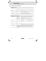
Betrieb mit Bemessungsleistung (Normalbetrieb)
Daten gelten für Betrieb an Netz−Bemessungsspannung und Schaltfrequenz 8 kHz (sinus).
Daten und Einschränkungen für andere Schaltfrequenzen: Siehe Betriebsanleitung.
Typ
Leistung
Netz−Bemessungsspannung
[kW]
Netzstrom
[A]
Ausgangsstrom [A]
IN
Imax
(60 s) 1)
3.4
1.7
2.5
5.0
2.4
3.6
PN
E82EV251
0.25
E82EV371
0.37
1)
1 N PE AC 230 / 240 V bzw.
2 PE AC 230 / 240 V:
180 V −0 % ... 264 V +0 %
45 Hz −0 % ... 65 Hz +0 %
Ströme für periodisches Lastwechselspiel: 1 min Überstromdauer mit Imax und 2 min Grundlastdauer
mit 75 % IN
EDK82MV371 DE/EN/FR 7.0
21
3
Technische Daten
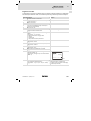
Abmessungen
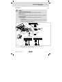
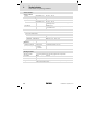
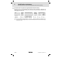
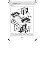
Abmessungen
c
b
e
f
a
Typ
E82MV251_2B
E82MV371_2B
d
8200mot043
a [mm]
b [mm]
c [mm]
d [mm]
e [mm]
f [mm]
140
100
90
189
7
12
Mechanische Ausführung
Typ
Verschraubungen
E82MV251_2B
E82MV371_2B
4 × M20 / 2 × M16 (Gewindelänge 10 mm, ohne Gegenmutter)
22
Gewicht
2.3 kg
EDK82MV371 DE/EN/FR 7.0
Mechanische Installation
4
motec mit Motor oder Getriebemotor
4
Mechanische Installation
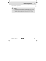
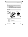
motec mit Motor oder Getriebemotor
Gefahr!
ƒ Alle Steuerklemmen sind nach dem Anschluss eines Kaltleiters (PTC) oder
eines Thermokontakts nur noch basisisoliert (einfache Trennstrecke).
ƒ Berührsicherheit bei defekter Trennstrecke ist nur durch externe
Maßnahmen gewährleistet, z. B. doppelte Isolierung.
EDK82MV371 DE/EN/FR 7.0
23
4
Mechanische Installation
motec mit Motor oder Getriebemotor
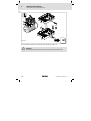
1b
1a
1a
Abb. 4−0
M20
M16
4×
2×
X2
1a
35
8200mot048
Motortemperatur−Überwachung mit C0119 aktivieren (z. B. C0119 = 1)!
Gefahr!
Die Verbindung zwischen Klemme X2 und Blech darf nicht gelöst werden!
24
EDK82MV371 DE/EN/FR 7.0
Mechanische Installation
4
motec mit Motor oder Getriebemotor
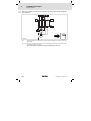
EMV−gerechte Verdrahtung
Bedingungen für störungsfreien Betrieb:
ƒ Mit Ausnahme der Netzleitung nur geschirmte Leitungen verwenden.
ƒ Schirmung sorgfältig auf PE legen.
ƒ Motor− und Netz−Schutzleiter an getrennte PE−Klemmen schrauben.
Schirmauflage:
1. Leitung vorbereiten
B
X1
2. Kabelbinder einlegen
A
C
E
F
3. Leitung einlegen und
Kabelbinder anziehen.
Die Abschirmung muss
fest mit dem Schirmblech verbunden sein.
D
8200mot151
Netzleitung L1, N, PE bzw. L1, L2, PE
Geschirmte Steuerleitung
PE−Anschluss Netzleitung
PE−Anschluss Motor
Schirmauflage Steuerleitung; Schirm mit Kabelbinder fest auf dem Blech fixieren
Funktionsmodul
X1
Klemmenleiste Netzanschluss
PES
HF−Schirmabschluss durch großflächige Anbindung an PE
EDK82MV371 DE/EN/FR 7.0
25
4
Mechanische Installation
Wandmontage
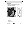
Wandmontage
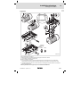
Lieferumfang
2
1b
M4 × 25
3
1a
4×
8200mot049
1a
Trägergehäuse
1b
Elektronikmodul
2
Distanz− und Wandplatte
3
Selbstformschrauben für die Wandmontage
26
EDK82MV371 DE/EN/FR 7.0
Mechanische Installation
4
Wandmontage
Vorbereitung
c
b
5.3 mm
2
d
a
M20
M16
4×
2×
1a
e
1a
3.4 Nm
30 lb-in
2
1a
3
8200mot050
Typ
E82MV251_2B
E82MV371_2B
Distanz− und Wandplatte
Bohrbild
Abstand
a [mm]
b [mm]
c [mm]
d [mm]
e [mm]
85
110
71
96
12
EDK82MV371 DE/EN/FR 7.0
27
4
Mechanische Installation
Wandmontage
Motorseitige Verdrahtung
Gefahr!
ƒ Alle Steuerklemmen sind nach dem Anschluss eines Kaltleiters (PTC) oder
eines Thermokontakts nur noch basisisoliert (einfache Trennstrecke).
ƒ Berührsicherheit bei defekter Trennstrecke ist nur durch externe
Maßnahmen gewährleistet, z. B. doppelte Isolierung.
Gefahr!
Die Verbindung zwischen Klemme X2 und Blech darf nicht gelöst werden!
0.5...0.6 Nm
4.4…5.3 lb-in
!
5.5 mm
2.5 mm2
AWG 12
A
3.4 Nm
30 lb-in
6mm
W V
B
5.5 mm
X2
U PE T2 T1
T2
T1
PE
X2
J>
1a
8200mot052
Kapazitätsarme Motorleitung verwenden! (Ader/Ader £75 pF/m, Ader/Schirm £150 pF/m)
Eine möglichst kurze Motorleitung wirkt sich positiv auf das Antriebsverhalten aus!
Leitungsquerschnitte U, V, W, PE:
E82MV251_2B
®
1 mm2 (AWG 18), geschirmt
E82MV371_2B
®
1 mm2 (AWG 18), geschirmt
Für die Motortemperatur−Überwachung separate Leitung (geschirmt) zu X2/T1 und X2/T2 verlegen.
Steuerleitungen und Netzleitungen von der Motorleitung räumlich getrennt verlegen!
28
EDK82MV371 DE/EN/FR 7.0
Mechanische Installation
4
Wandmontage
X2
W V U PE T2 T1
PES
PES
PES
PES
ϑ>
M
3~
PE
PTC
M
3~
35
8200mot051
HF−Schirmabschluss durch PE−Anbindung über Schirmauflage ( 30) bzw. Motor−EMV−Verschraubung.
X2/ T1, T2 Anschlussklemmen Motortemperatur−Überwachung mit Kaltleiter (PTC) oder Thermokontakt
(Öffner).
Motortemperatur−Überwachung mit C0119 aktivieren (z. B. C0119 = 1)!
PES
EDK82MV371 DE/EN/FR 7.0
29
4
Mechanische Installation
Wandmontage
EMV−gerechte Verdrahtung
Bedingungen für störungsfreien Betrieb:
ƒ Außer der Netzleitung nur geschirmte Leitungen verwenden.
ƒ Schirmung sorgfältig auf PE legen.
ƒ Steuer− und Netzleitung räumlich getrennt von Motorleitung verlegen!
ƒ Motor− und Netz−Schutzleiter an getrennte PE−Klemmen schrauben.
Schirmauflage:
1. Leitung vorbereiten
B
Abb. 4−2
X2
X1
C
A
2. Kabelbinder einlegen
D
E
F
H
Abb. 4−1
G
3. Leitung einlegen und
Kabelbinder anziehen.
Die Abschirmung muss
fest mit dem Schirmblech verbunden sein.
8200mot169
Netzleitung L1, N, PE bzw. L1, L2, PE
Schirmauflage Motorleitung; Schirm mit Kabelbinder fest auf dem Blech fixieren
Schirmauflage Steuerleitung (Schirm mit Kabelbinder fest auf dem Blech fixieren)
PE−Anschluss Netzleitung
Geschirmte Motorleitung (kapazitätsarme Motorleitungen verwenden)
PE−Anschluss Motorleitung
Geschirmte Steuerleitung
Funktionsmodul
X1
Klemmenleiste Netzanschluss
X2
Klemmenleiste Motoranschluss
PES
HF−Schirmanschluss durch großflächige Anbindung an PE
30
EDK82MV371 DE/EN/FR 7.0
Mechanische Installation
4
Motormontage
Motormontage
Lieferumfang
2
1b
M4 × 25
3
1a
4×
8200mot049
1a
Trägergehäuse
1b
Elektronikmodul
2
Distanz− und Wandplatte
3
Selbstformschrauben für die Wandmontage
EDK82MV371 DE/EN/FR 7.0
31
4
Mechanische Installation
Motormontage
Vorbereitung
68mm
B
3.4 Nm
30 lb-in
5mm
68mm
A
1a
2
A
Abb. 4−3
1a
1a
M20
M16
4×
2×
8200mot053
Vorbereitende Arbeiten am Motor:
l Klemmenkastendichtung und Motor−Klemmbrett entfernen.
l Ggf. Motorleitung verlängern.
Gehäusewanne auf Motor montieren:
Wenn Distanz erforderlich ist, mitgelieferte Distanz− und Wandplatte (2) und Klemmenkastendichtung verwenden.
l Die verwendete Befestigung muss die mechanische Verbindung dauerhaft ermöglichen, z. B. durch
Einsatz von Fächerscheiben .
Schutzart IP65 ist nur bei sorgfältiger Abdichtung gewährleistet.
l
32
EDK82MV371 DE/EN/FR 7.0
Mechanische Installation
4
Motormontage
Motoranschluss
Gefahr!
ƒ Alle Steuerklemmen sind nach dem Anschluss eines Kaltleiters (PTC) oder
eines Thermokontakts nur noch basisisoliert (einfache Trennstrecke).
ƒ Berührsicherheit bei defekter Trennstrecke ist nur durch externe
Maßnahmen gewährleistet, z. B. doppelte Isolierung.
Gefahr!
Die Verbindung zwischen Klemme X2 und Blech darf nicht gelöst werden!
0.5...0.6 Nm
4.4…5.3 lb-in
2.5 mm2
AWG 12
6mm
!
W V
Abb. 4−4
5.5 mm
5.5 mm
3.4 Nm
30 lb-in
X2
U PE T2 T1
T2
W2 U2 V2
T1
PE
U1 V1 W1 PE
J>
X2
35
1a
8200mot055
X2/ T1,T2 Anschlussklemmen Motortemperatur−Überwachung mit Kaltleiter (PTC) oder Thermokontakt
(Öffner).
Motortemperatur−Überwachung mit C0119 aktivieren (z. B. C0119 = 1)!
EDK82MV371 DE/EN/FR 7.0
33
4
Mechanische Installation
Motormontage
EMV−gerechte Verdrahtung
Bedingungen für störungsfreien Betrieb:
ƒ Außer der Netzleitung nur geschirmte Leitungen verwenden.
ƒ Schirmung sorgfältig auf PE legen.
ƒ Motor− und Netz−Schutzleiter an getrennte PE−Klemmen schrauben.
Schirmauflage:
1. Leitung vorbereiten
B
X2
X1
A
2. Kabelbinder einlegen
C
D
Abb. 4−5
E
F
3. Leitung einlegen und
Kabelbinder anziehen.
Die Abschirmung muss
fest mit dem Schirmblech verbunden sein.
8200mot151
Netzleitung L1, N, PE bzw. L1, L2, PE
PE−Anschluss Netzleitung
Geschirmte Steuerleitung
X1
Klemmenleiste Netzanschluss
X2
Klemmenleiste Motoranschluss
PES
HF−Schirmanschluss durch grossflächige Anbindung an PE
34
PE−Anschluss Motor
Schirmauflage Steuerleitung (Schirm mit Kabelbinder fest auf dem Blech fixieren)
Funktionsmodul
EDK82MV371 DE/EN/FR 7.0
Elektrische Installation
5
Netzanschluss
5
Elektrische Installation
Netzanschluss
Gefahr!
Gefährliche elektrische Spannung
Der Ableitstrom gegen Erde (PE) ist > 3,5 mA AC bzw. 10 mA DC.
Mögliche Folgen:
ƒ Tod oder schwere Verletzungen beim Berühren des Gerätes im Fehlerfall.
Schutzmaßnahmen:
ƒ Die in der EN 61800−5−1 geforderten Maßnahmen umsetzen.
Insbesondere:
– Festinstallation
– PE−Anschluss normgerecht ausführen (PE−Leiterdurchmesser ³ 10 mm2
(Cu) oder PE−Leiter doppelt auflegen)
X1 K11 K12 K14
BR1 BR2 L1 L2/N L3
PE
5.5 mm
K11 K12 K14
37
X1
1a
Abb. 5−0
2.5 mm2
AWG 12
0.5 … 0.6 Nm
4.4 … 5.3 lb-in
6mm
3.4 Nm
30 lb-in
L1
L2
L3
PE
8200mot057
X1
2/PE AC 180V...264V 45...65Hz
L1
N
PE
1/N/PE AC 180V...264V 45...65Hz
F1
F1
K1
K1
X1
L1 L2/N
L1 L2/N
L3
Klemme X1/L3 ist ohne Funktion (Verwendung z. B. als Stützpunkt−Klemme).
X1/ BR1, BR2
Anschlussklemmen Bremswiderstand (Option)
EDK82MV371 DE/EN/FR 7.0
35
5
Elektrische Installation
Netzanschluss
Sicherungen und Leitungsquerschnitte
Typ
E82MV251_2B
E82MV371_2B
FI 1)
Installation nach EN 60204−1
Netz
Schmelzsicherung
Sicherungsautomat
L1, L2, N, PE
[mm2]
M10 A
C10 A
1.5
2/PE AC bzw.
1/N/PE AC
180 ... 264 V;
45 ... 65 Hz
³ 30 mA
1)
Pulsstromsensitiver oder allstromsensitiver Fehlerstrom−Schutzschalter
Nationale und regionale Vorschriften beachten
Beachten Sie bei Einsatz von Fehlerstrom−Schutzschaltern:
ƒ Fehlerstrom−Schutzschalter nur zwischen speisendem Netz und Antriebsregler
installieren.
ƒ Fehlerstrom−Schutzschalter kann falsch auslösen durch
– kapazitive Ausgleichsströme der Leitungsschirme während des Betriebs (vor
allem bei langen, geschirmten Motorleitungen),
– gleichzeitiges Zuschalten mehrerer Antriebsregler ans Netz.
Dimensionierung von Netzschützen
Bemessungsstrom Netzschütz
Typ
E82MV251_2B
E82MV371_2B
mit Einschaltstrombegrenzung 1)
ohne Einschaltstrombegrenzung
10 A
20 A
Nationale und regionale Vorschriften beachten
1) z.B. Strombegrenzungsmodul E82ZJ004
36
EDK82MV371 DE/EN/FR 7.0
Elektrische Installation
5
Anschluss Relaisausgang
Anschluss Relaisausgang
8200 motec
X1 K11 K12 K14
Abb. 5−1
PES
X1
PES
1a
8200mot058
Funktion
Relaisstellung
Meldung
(Lenze−Einstellung)
X1/K11
Öffner
geöffnet
TRIP
X1/K12
Mittelkontakt
X1/K14
Schließer
geschlossen
TRIP
PES
HF−Schirmabschluss durch großflächige Anbindung an PE
Hinweis!
Technische Daten
AC 250 V/3 A
DC 24 V/2 A ... DC 240 V/0.22 A
ƒ Schalten von Steuersignalen:
– Geschirmte Leitungen verwenden
– HF−Schirmabschluss durch PE−Anbindung
– Die Mindestbelastung für ein einwandfreies Durchschalten der Signale
ƒ
ƒ
ƒ
ƒ
beträgt 12 V und 5 mA. Beide Werte müssen gleichzeitig überschritten
werden.
Schalten von Netzpotenzialen:
– Ungeschirmte Leitungen sind ausreichend
Zum Schutz der Relaiskontakte ist bei induktiver oder kapazitiver Last
eine entsprechende Schutzbeschaltung unbedingt notwendig!
Die Lebensdauer des Relais ist abhängig von der Art der Belastung
(ohmsch, induktiv oder kapazitiv) und dem Wert der Schaltleistung.
Die ausgegebene Meldung können Sie in den Codestellen C0008 oder
C0415/1 ändern.
EDK82MV371 DE/EN/FR 7.0
37
5
Elektrische Installation
Montage Funktionsmodul (Option)
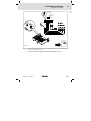
Montage Funktionsmodul (Option)
Stop!
ƒ Steuerleitungen immer abschirmen, um Störeinkopplungen zu
vermeiden!
ƒ Die FIF−Abdeckkappe am Elektronikmodul und die Schutzkappe des
Funktionsmoduls entfernen. Sonst können der motec oder das
Funktionsmodul beschädigt werden.
1
klick
2
B
1a
3
A
1a
4
1b
0.5...0.6 Nm
4.4...5.3 lb-in
X3
1 mm 2
AWG 18
PES
PES
6mm
8200mot153
1.
2.
3.
4.
38
Funktionsmodul in die Halterung stecken.
Schutzkappe des Funktionsmoduls entfernen und aufbewahren.
FIF−Abdeckkappe entfernen und aufbewahren!
Verdrahtung: siehe Montageanleitung des Funktionsmoduls.
EDK82MV371 DE/EN/FR 7.0
Abschließende Arbeiten
6
motec zusammenbauen
6
Abschließende Arbeiten
motec zusammenbauen
motec mit Funktionsmodul
Stop!
ƒ Vor dem Zusammenbau unbedingt Schutzkappe des Funktionsmoduls und FIF−Abdeckkappe entfernen und aufbewahren! Sonst kann der
motec beschädigt werden!
ƒ Vor Inbetriebnahme mit dem Aufkleber , der dem Funktionsmodul
beiliegt, das motec−Typenschild vervollständigen.
IP65
2.4 Nm
21 lb-in
1
0
2
Standard-I/O
AIF
S
8200mot059
EDK82MV371 DE/EN/FR 7.0
39
6
Abschließende Arbeiten
motec zusammenbauen
motec ohne Funktionsmodul
Stop!
FIF−Abdeckkappe muss gesteckt sein. Der motec ist nur so funktionsfähig!
IP65
2.4 Nm
21 lb-in
AIF
0
40
EDK82MV371 DE/EN/FR 7.0
Inbetriebnahme
7
Vor dem ersten Einschalten
7
Inbetriebnahme
Vor dem ersten Einschalten
Hinweis!
ƒ Halten Sie die jeweilige Einschaltreihenfolge ein.
ƒ Bei Störungen während der Inbetriebnahme hilft Ihnen das Kapitel
"Fehlersuche und Störungsbeseitigung".
Um Personenschäden oder Sachschäden zu vermeiden, überprüfen Sie vor dem
Zuschalten der Netzspannung:
ƒ Die Verdrahtung auf Vollständigkeit, Kurzschluss und Erdschluss
ƒ Die Funktion "NOT−AUS" der Gesamtanlage
ƒ Die Schaltungsart des Motors (Stern/Dreieck); sie muss an die Ausgangsspannung
des Antriebsreglers angepasst sein.
ƒ Wenn kein Funktionsmodul verwendet wird, muss die FIF−Abdeckkappe aufgesteckt
sein (Lieferzustand).
ƒ Wenn die interne Spannungsquelle X3/20 z. B. des Standard−I/O verwendet wird,
müssen die Klemmen X3/7 und X3/39 gebrückt sein.
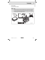
EDK82MV371 DE/EN/FR 7.0
41
7
Inbetriebnahme
Betriebsart wählen
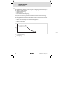
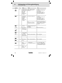
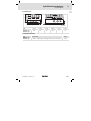
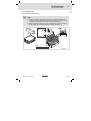
Betriebsart wählen
Über die Betriebsart wählen Sie die Steuerungsart oder Regelungsart des Antriebsreglers
aus. Sie können wählen zwischen
ƒ U/f−Kennliniensteuerung
ƒ Vectorregelung
ƒ Sensorlose Drehmomentregelung
Die U/f−Kennliniensteuerung ist die klassische Betriebsart für Standardanwendungen.
Mit der Vector−Regelung erzielen Sie gegenüber der U/f−Kennliniensteuerung verbesserte
Antriebseigenschaften durch:
ƒ höheres Drehmoment über den gesamten Drehzahlbereich
ƒ höhere Drehzahlgenauigkeit und höhere Rundlaufgüte
ƒ höheren Wirkungsgrad
M
MN
nN
42
n
8200vec524
U/f−Kennliniensteuerung
Vectorregelung
EDK82MV371 DE/EN/FR 7.0
Inbetriebnahme
7
Betriebsart wählen
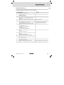
Empfohlene Betriebsarten für Standardanwendungen
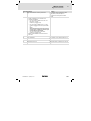
Für Standardanwendungen hilft Ihnen die folgende Tabelle, die richtige Betriebsart zu
wählen:
Anwendung
Betriebsart
Einstellung in C0014
empfohlen
alternativ
mit stark wechselnden Lasten
4
2
mit Schweranlauf
4
2
mit Drehzahlregelung (Drehzahlrückführung)
2
4
mit hoher Dynamik (z. B. Positionier− und Zustellantriebe)
2
−
mit Drehmoment−Sollwert
5
−
mit Drehmomentbegrenzung (Leistungsregelung)
2
4
Drehstrom−Reluktanzmotoren
2
−
Drehstrom−Verschiebeankermotoren
2
−
Drehstrommotoren mit fest zugeordneter Frequenz−Spannungskennlinie
2
−
Pumpen− und Lüfterantriebe mit quadratischer Lastkennlinie
3
2 oder 4
gleiche Motoren und gleiche Lasten
2
−
unterschiedliche Motoren und/oder wechselnde Lasten
2
−
Einzelantriebe
Gruppenantriebe
(mehrere Motoren an einem Antriebsregler angeschlossen)
C0014 = 2: lineare U/f−Kennliniensteuerung
C0014 = 3: quadratische U/f−Kennliniensteuerung
C0014 = 4: Vector−Regelung
C0014 = 5: sensorlose Drehmoment−Regelung
EDK82MV371 DE/EN/FR 7.0
43
7
Inbetriebnahme
Parametrierung mit dem Handterminal E82ZBB
Parametrierung mit dem Handterminal E82ZBB
Beschreibung
Das Handterminal ist als Zubehör erhältlich. Das Handterminal besteht aus einer gummierten Hülle in der das Keypad E82ZBC montiert ist. Für den Anschluss an den Antriebsregler benötigen Sie eine separate Anschlussleitung Typ E82ZWL. Die vollständige Beschreibung des Keypads finden Sie in der im Lieferumfang beiliegenden Anleitung.
Handterminal anschließen
Sie können das Handterminal auch während des Betriebs mit der AIF−Schnittstelle des Antriebsreglers verbinden und wieder davon trennen.
Sobald das Keypad mit Spannung versorgt wird, führt es einen Selbsttest aus. Das Keypad
ist betriebsbereit, wenn es sich im Anzeigemodus befindet.
44
EDK82MV371 DE/EN/FR 7.0
Inbetriebnahme
7
U/f−Kennliniensteuerung
U/f−Kennliniensteuerung
Die folgende Beschreibung gilt für den Antriebsregler mit Funktionsmodul Standard−I/O
und leistungszugeordnetem Drehstrom−Asynchronmotor.
Einschaltreihenfolge
Bemerkung
1.
Schließen Sie das Keypad an
2.
Stellen Sie sicher, dass nach Netz−Einschalten die
Reglersperre aktiv ist
3.
Schalten Sie das Netz ein
4.
Nach ca. 2 s befindet sich das Keypad im Anzeigemodus Disp" und zeigt die Ausgangsfrequenz
(C0050) an
5.
Wechseln Sie in den Modus , damit Sie die Grun- Im Display blinkt 0050
deinstellungen für Ihren Antrieb ausführen können
6.
Passen Sie Spannungsbereich/Strombereich für die DIP−Schalter auf dem Standard−I/O auf
analoge Sollwertvorgabe an (C0034)
den gleichen Bereich einstellen (siehe
Lenze−Einstellung: −0−, (0 ... 5 V/0 ... 10 V/0 ... 20 mA) Montageanleitung des Standard−I/O)
7.
Passen Sie die Klemmenkonfiguration an die Verdrahtung an (C0007)
Lenze−Einstellung: −0−, d. h.
E1: JOG1/3 Auswahl Festsollwerte
E2: JOG2/3
E3: DCB Gleichstrombremse
E4: CW/CCW Rechtslauf/Linkslauf
8.
Stellen Sie die minimale Ausgangsfrequenz ein
(C0010)
Lenze−Einstellung: 0.00 Hz
9.
Stellen Sie die maximale Ausgangsfrequenz ein
(C0011)
Lenze−Einstellung: 50.00 Hz
10.
Stellen Sie die Hochlaufzeit Tir ein (C0012)
Lenze−Einstellung: 5.00 s
11.
Stellen Sie die Ablaufzeit Tif ein (C0013)
Lenze−Einstellung: 5.00 s
12.
Stellen Sie die U/f−Nennfrequenz ein (C0015)
Lenze−Einstellung: 50.00 Hz
13.
Stellen Sie die Umin−Anhebung ein (C0016)
Lenze−Einstellung: hängt ab vom Antriebsreglertyp
EDK82MV371 DE/EN/FR 7.0
Klemme X3/28 = LOW
Das Menü USEr ist aktiv
Die Lenze−Einstellung ist für alle gängigen
Anwendungen geeignet
45
7
Inbetriebnahme
U/f−Kennliniensteuerung
Einschaltreihenfolge
Bemerkung
14.
Wenn Sie weitere Einstellungen vornehmen wollen, Z. B. Festfrequenzen (JOG) (C0037, C0038,
müssen Sie in das Menü ALL wechseln
C0039) oder Motortemperatur−Überwachung (C0119) aktivieren
15.
Wechseln Sie in das Menü ALL
A Prüfen Sie die Einstellung für die Lüfterüberwachung in der Codestelle C0608:
– für 8200 motec 0.25...0.37 kW u. 0.55...2.2
kW:
C0608 = 0 ! (Werkseinstellung)
– für 8200 motec 3...7.5 kW:
C0608 =1 (empfohlen) oder C0608 = 2!
Stop!
Funktion unbedingt bei der Inbetriebnahme
aktivieren! Der Antriebsregler kann sonst
durch Überhitzung zerstört werden!
– alle anderen Antriebsregler:
C0608 = 0 ! (Werkseinstellung)
B Stellen Sie ggf. weitere Funktionen über Codestellen ein.
Wenn Sie alle Einstellungen abgeschlossen haben:
16.
Sollwert vorgeben
Z. B. über Potentiometer an den Klemmen 7, 8, 9
17.
Regler freigeben
Klemme X3/28 = HIGH
18.
Der Antrieb läuft jetzt.
Wenn der Antrieb nicht anläuft, zusätzlich
drücken
46
EDK82MV371 DE/EN/FR 7.0
Inbetriebnahme
7
Vector−Regelung
Vector−Regelung
Die folgende Beschreibung gilt für den Antriebsregler mit Funktionsmodul Standard−I/O
und leistungszugeordnetem Drehstrom−Asynchronmotor.
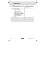
Einschaltreihenfolge
Bemerkung
1.
Schließen Sie das Keypad an
2.
Stellen Sie sicher, dass nach Netz−Einschalten die
Reglersperre aktiv ist
3.
Schalten Sie das Netz ein
4.
Nach ca. 2 s befindet sich das Keypad im Anzeigemodus Disp" und zeigt die Ausgangsfrequenz
(C0050) an
5.
Wechseln Sie in das Menü ALL
6.
Wechseln Sie in den Modus , damit Sie die Grun- Im Display blinkt 0050
deinstellungen für Ihren Antrieb ausführen können
7.
Passen Sie die Klemmenkonfiguration an die Verdrahtung an (C0007)
Lenze−Einstellung: −0−, d. h.
E1: JOG1/3 Auswahl Festsollwerte
E2: JOG2/3
E3: DCB Gleichstrombremse
E4: CW/CCW Rechtslauf/Linkslauf
8.
Stellen Sie die minimale Ausgangsfrequenz ein
(C0010)
Lenze−Einstellung: 0.00 Hz
9.
Stellen Sie die maximale Ausgangsfrequenz ein
(C0011)
Lenze−Einstellung: 50.00 Hz
10.
Stellen Sie die Hochlaufzeit Tir ein (C0012)
Lenze−Einstellung: 5.00 s
11.
Stellen Sie die Ablaufzeit Tif ein (C0013)
Lenze−Einstellung: 5.00 s
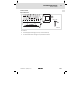
12.
Stellen Sie die Betriebsart "Vector−Regelung" ein (C0014 = 4)
Lenze−Einstellung: lineare
U/f−Kennliniensteuerung (C0014
= 2)
Klemme X3/28 = LOW
Das Menü USEr ist aktiv
dcbBA
SHPRG p
Menu
Code
Para
0014 00
4
Vector-Ctrl
9371BC008
13.
Passen Sie Spannungsbereich/Strombereich für die
analoge Sollwertvorgabe an (C0034)
Lenze−Einstellung: −0−, (0 ... 5 V/0 ... 10 V/0 ... 20 mA)
DIP−Schalter auf dem Standard−I/O auf
den gleichen Bereich einstellen (siehe
Montageanleitung des Standard−I/O)
14.
Geben Sie die Motordaten ein
Siehe Motor−Typenschild
A
Motor−Bemessungsdrehzahl (C0087)
Lenze−Einstellung: 1390 rpm
B
Motor−Bemessungsstrom (C0088)
Lenze−Einstellung: geräteabhängig
EDK82MV371 DE/EN/FR 7.0
Wert für die gewählte Motor−Schaltungsart (Stern/Dreieck) eintragen!
47
7
Inbetriebnahme
Vector−Regelung
C
Motor−Bemessungsfrequenz (C0089)
Lenze−Einstellung: 50 Hz
D
Motor−Bemessungsspannung (C0090)
Lenze−Einstellung: geräteabhängig
E
Motor−cosj (C0091)
Lenze−Einstellung: geräteabhängig
15.
Wert für die gewählte Motor−Schaltungsart (Stern/Dreieck) eintragen!
Starten Sie die Motorparameter−Identifizierung
(C0148)
Nur bei kaltem Motor durchführen!
A
Sicherstellen, dass der Regler gesperrt ist
Klemme X3/28 = LOW
B
C0148 = 1 einstellen
drücken
C
Regler freigeben
l
l
D
Wenn nach ca. 30 s das Segment wieder aktiv ist,
Regler wieder sperren.
l
l
l
l
16.
Stellen Sie ggf. weitere Parameter ein
17.
Wechseln Sie in das Menü ALL
A Prüfen Sie die Einstellung für die Lüfterüberwachung in der Codestelle C0608:
– für 8200 motec 0.25...0.37 kW u. 0.55...2.2 kW:
C0608 = 0 ! (Werkseinstellung)
– für 8200 motec 3...7.5 kW:
C0608 =1 (empfohlen) oder C0608 = 2!
Stop!
Funktion unbedingt bei der Inbetriebnahme
aktivieren! Der Antriebsregler kann sonst
durch Überhitzung zerstört werden!
– alle anderen Antriebsregler:
C0608 = 0 ! (Werkseinstellung)
B Stellen Sie ggf. weitere Funktionen über Codestellen ein.
Klemme X3/28 = HIGH
Die Identifizierung startet:
– Das Segment erlischt
– Der Motor wird bestromt und
pfeift" leise.
– Der Motor dreht sich nicht!
Klemme X3/28 = LOW
Die Identifizierung ist beendet.
Berechnet und gespeichert wurden:
– U/f−Nennfrequenz (C0015)
– Schlupfkompensation (C0021)
– Motor−Ständerinduktivität
(C0092)
Gemessen und gespeichert wurde:
– Motor−Ständerwiderstand
(C0084) = Gesamtwiderstand von
Motorleitung und Motor
Z. B. Festfrequenzen (JOG) (C0037,
C0038, C0039 oder Motortemperatur−
Überwachung aktivieren (C0119)
Wenn Sie alle Einstellungen abgeschlossen haben:
18.
Sollwert vorgeben
Z. B. über Potentiometer an den Klemmen 7, 8, 9
19.
Regler freigeben
Klemme X3/28 = HIGH
20.
Der Antrieb läuft jetzt.
Wenn der Antrieb nicht anläuft, zusätzlich drücken
48
EDK82MV371 DE/EN/FR 7.0
Inbetriebnahme
7
Vector−Regelung
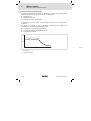
Vectorregelung optimieren
Die Vectorregelung ist nach der Motorparameter−Identifizierung in der Regel ohne weitere Maßnahmen betriebsfähig. Sie müssen die Vectorregelung nur bei folgendem Antriebsverhalten optimieren:
Antriebsverhalten
Abhilfe
Rauer Motorlauf und Motorstrom (C0054) > 60 %
Motor−Bemessungsstrom im Maschinenleerlauf
(stationärer Betrieb)
1. Motor−Ständerinduktivität (C0092) um 10 %
verringern
2. Motorstrom in C0054 prüfen
3. Ist der Motorstrom (C0054) > 50 % Motor−Bemessungsstrom:
– C0092 weiter verringern, bis der Motorstrom
ca. 50 % des Motor−Bemessungsstroms beträgt
– C0092 max. um 20 % verringern!
– Beachten Sie: Wenn Sie C0092 verringern,
nimmt das Drehmoment ab!
Zu geringes Drehmoment bei Frequenzen f <
5 Hz (Anlaufmoment)
Motorwiderstand (C0084) vergrößern oder Motorinduktivität (C0092) vergrößern
Mangelnde Drehzahlkonstanz bei hoher Belastung
(Sollwert und Motor−Drehzahl sind nicht mehr proportional)
Schlupfkompensation (C0021) vergrößern
Überkompensation macht den Antrieb instabil!
Fehlermeldungen OC1, OC3, OC4 oder OC5 bei
Hochlaufzeiten (C0012) < 1 s (Antriebsregler kann
den dynamischen Vorgängen nicht mehr folgen)
Nachstellzeit des Imax−Reglers (C0078) verändern:
l C0078 verringern = Imax−Regler wird schneller
(dynamischer)
l C0078 vergrößern = Imax−Regler wird langsamer
("weicher")
EDK82MV371 DE/EN/FR 7.0
49
7
Inbetriebnahme
Wichtige Antriebsregler−Codestellen
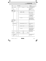
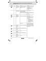
Wichtige Antriebsregler−Codestellen
Hinweis!
ƒ Die folgende Tabelle beschreibt ausführlich die in den
Inbetriebnahme−Beispielen genannten Codes!
ƒ Ändern Sie keine Codes, deren Bedeutung Sie nicht kennen! Sie finden
alle Codes ausführlich beschrieben im Systemhandbuch.
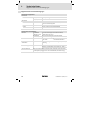
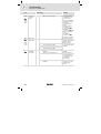
So lesen Sie die Codetabelle
Spalte
Abkürzung
Bedeutung
Code
Cxxxx
Code Cxxxx
1
Subcode 1 von
Cxxxx
2
Subcode 2 von
Cxxxx
l
l
Parameterwert des Code kann in jedem
Parametersatz unterschiedlich definiert
sein
Parameterwert wird sofort übernommen (ONLINE)
*
Parameterwert des Code ist in allen Parametersätzen gleich und
kann im Parametersatz 1 geändert werden
Keypad E82ZBC
Geänderter Parameter des Code oder Subcode wird nach Drücken von übernommen
Keypad XT
EMZ9371BC
Geänderter Parameter des Code oder Subcode wird nach Drücken von ! " übernommen
Keypad E82ZBC
Geänderter Parameter des Code oder Subcode wird nach Drücken von übernommen, wenn der Regler gesperrt ist
Keypad XT
EMZ9371BC
Geänderter Parameter des Code oder Subcode wird nach Drücken von ! " übernommen, wenn der Regler gesperrt ist
#
(A)
Code, Subcode oder Auswahl nur verfügbar bei Betrieb mit Application−I/O
uSEr
Code ist in der Lenze−Einstellung im USER−Menü enthalten
Bezeichnung
Bezeichnung des Code
Lenze
Lenze−Einstellung (Wert bei Auslieferung oder nach Wiederherstellen des Lieferzustands mit C0002)
à
Auswahl
1
WICHTIG
−
50
Die Spalte "WICHTIG" enthält weitere Information
{%}
99 min. Wert
{Einheit}
max. Wert
Kurze, wichtige Erläuterungen
EDK82MV371 DE/EN/FR 7.0
Inbetriebnahme
7
Wichtige Antriebsregler−Codestellen
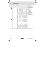
Code
Einstellmöglichkeiten
Nr.
Bezeichnung
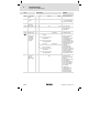
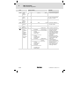
C0002*
Parametersatzverwaltung
#
uSEr
Lieferzustand wiederherstellen
C0002*
#
uSEr
WICHTIG
Lenze Auswahl
0
0
Bereit
1
Lenze−Einstellung ð PAR1
2
Lenze−Einstellung ð PAR2
3
Lenze−Einstellung ð PAR3
4
Lenze−Einstellung ð PAR4
31
Lenze−Einstellung ð FPAR1
Lieferzustand wiederherstellen im Feldbus−Funktionsmodul
61
Lenze−Einstellung ð PAR1 +
FPAR1
62
Lenze−Einstellung ð PAR2 +
FPAR1
63
Lenze−Einstellung ð PAR3 +
FPAR1
Lieferzustand wiederherstellen im gewählten Parametersatz des Antriebsreglers
und im Feldbus−Funktionsmodul
64
Lenze−Einstellung ð PAR4 +
FPAR1
Parametersätze mit
Keypad
übertragen
(Forts.)
Keypad ð Antriebsregler
EDK82MV371 DE/EN/FR 7.0
70
mit Funktionsmodul Application−I/O, INTERBUS, PROFIBUS−
DP, LECOM−B, DeviceNet,
CANopen
10
mit allen anderen Funktionsmodulen
PAR1 ... PAR4:
l Parametersätze des Antriebsreglers
l PAR1 ... PAR4 enthalten
auch die Parameter für
die Funktionsmodule
Standard−I/O, Application−I/O, AS−interface,
Systembus (CAN)
FPAR1:
l Modulspezifischer Parametersatz der Feldbus−
Funktionsmodule INTERBUS, PROFIBUS−DP, LECOM−B, DeviceNet/CANopen
l FPAR1 wird im Funktionsmodul gespeichert
Lieferzustand wiederherstellen im gewählten Parametersatz
Mit dem Keypad können Sie
die Parametersätze zu anderen Antriebsreglern übertragen.
Während der Übertragung
ist der Zugriff auf die Parameter über andere Kanäle
gesperrt!
Alle verfügbaren Parametersätze (PAR1 ... PAR4, ggf.
FPAR1) mit den entsprechenden Daten des Keypad
überschreiben
51
7
Inbetriebnahme
Wichtige Antriebsregler−Codestellen
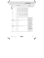
Code
Einstellmöglichkeiten
Nr.
Bezeichnung
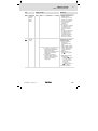
C0002*
Parametersätze mit
Keypad
übertragen
#
uSEr
WICHTIG
Lenze Auswahl
Keypad ð PAR1 (+ FPAR1)
71
mit Funktionsmodul Application−I/O, INTERBUS, PROFIBUS−
DP, LECOM−B, DeviceNet/CANopen
11
mit allen anderen Funktionsmodulen
(Forts.)
Gewählten Parametersatz
und ggf. FPAR1 mit den entsprechenden Daten des
Keypad überschreiben
Keypad ð PAR2 (+ FPAR1)
72
mit Funktionsmodul Application−I/O, INTERBUS, PROFIBUS−
DP, LECOM−B, DeviceNet/CANopen
12
mit allen anderen Funktionsmodulen
Keypad ð PAR3 (+ FPAR1)
73
mit Funktionsmodul Application−I/O, INTERBUS, PROFIBUS−
DP, LECOM−B, DeviceNet/CANopen
13
mit allen anderen Funktionsmodulen
Keypad ð PAR4 (+ FPAR1)
74
mit Funktionsmodul Application−I/O, INTERBUS, PROFIBUS−
DP, LECOM−B, DeviceNet/CANopen
14
mit allen anderen Funktionsmodulen
Antriebsregler ð Keypad
80
mit Funktionsmodul Application−I/O, INTERBUS, PROFIBUS−
DP, LECOM−B, DeviceNet/CANopen
20
mit allen anderen Funktionsmodulen
Keypad ð Funktionsmodul
40
nur mit Funktionsmodul INTERBUS, PROFIBUS−DP, LECOM−B,
DeviceNet/CANopen
Funktionsmodul ð Keypad
50
52
nur mit Funktionsmodul INTERBUS, PROFIBUS−DP, LECOM−B,
DeviceNet/CANopen
Alle verfügbaren Parametersätze (PAR1 ... PAR4, ggf.
FPAR1) in das Keypad kopieren
Nur den modulspezifischen
Parametersatz FPAR1 mit
den Daten des Keypad überschreiben
Nur den modulspezifischen
Parametersatz FPAR1 in das
Keypad kopieren
EDK82MV371 DE/EN/FR 7.0
Inbetriebnahme
7
Wichtige Antriebsregler−Codestellen
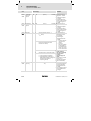
Code
Einstellmöglichkeiten
Nr.
Bezeichnung
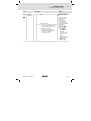
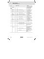
C0002*
eigene
Grundeinstellung
speichern
#
uSEr
9
(Forts.)
C0002*
#
uSEr
(Forts.)
eigene
Grundeinstellung laden/kopieren
Parameter
nichtflüchtig
speichern
7
8
eigene Grundeinstellung ð PAR4
0
Parameter nicht im EEPROM
speichern
Datenverlust nach Netzausschalten
1
Parameter immer im EEPROM
speichern
l
5
1
PAR1 ð eigene Grundeinstellung Sie können für die Parameter des Antriebsreglers eine
eigene Grundeinstellung
speichern (z. B. den Lieferzustand Ihrer Maschine):
1. Sicherstellen, dass Parametersatz 1 aktiv ist
2. Regler sperren
3. C0003 = 3 setzen, bestätigen mit 4. C0002 = 9 setzen, bestätigen mit , die eigene
Grundeinstellung ist gespeichert
5. C0003 = 1 setzen, bestätigen mit 6. Regler freigeben
Sie können mit dieser Funktion auch einfach PAR1 in
die Parametersätze PAR2 ...
PAR4 kopieren
eigene Grundeinstellung ð PAR1 Eigene Grundeinstellung
wiederherstellen im gewähleigene Grundeinstellung ð PAR2
ten Parametersatz
eigene Grundeinstellung ð PAR3
6
C0003*
WICHTIG
Lenze Auswahl
l
3
EDK82MV371 DE/EN/FR 7.0
eigene Grundeinstellung im
EEPROM speichern
Nach jedem Netzeinschalten aktiv
Zyklisches Ändern von
Parametern über Busmodul ist nicht erlaubt
Anschließend mit C0002 = 9
Parametersatz 1 als eigene
Grundeinstellung speichern
53
7
Inbetriebnahme
Wichtige Antriebsregler−Codestellen
Code
Einstellmöglichkeiten
Nr.
Bezeichnung
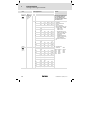
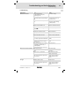
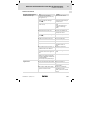
C0007
Feste Konfiguration digitale Eingänge
uSEr
Änderung von C0007 wird in
den entsprechenden Subcode von C0410 kopiert.
Freie Konfiguration in C0410
setzt C0007 = 255!
0
E4
E3
E2
E1
0
CW/
CCW
DCB
JOG2/3
JOG1/3
1
CW/
CCW
PAR
JOG2/3
JOG1/3
2
CW/
CCW
QSP
JOG2/3
JOG1/3
3
CW/
CCW
PAR
DCB
JOG1/3
4
CW/
CCW
QSP
PAR
JOG1/3
5
CW/
CCW
DCB
TRIP−
Set
JOG1/3
6
CW/
CCW
PAR
TRIP−
Set
JOG1/3
7
CW/
CCW
PAR
DCB
TRIP−
Set
8
CW/
CCW
QSP
PAR
TRIP−
Set
9
CW/
CCW
QSP
TRIP−
Set
JOG1/3
10
CW/
CCW
TRIP−
Set
UP
DOWN
E4
E3
E2
E1
11
CW/
CCW
DCB
UP
DOWN
12
CW/
CCW
PAR
UP
DOWN
13
CW/
CCW
QSP
UP
DOWN
14
CCW/
QSP
CW/
QSP
DCB
JOG1/3
15
CCW/
QSP
CW/
QSP
PAR
JOG1/3
16
CCW/
QSP
CW/
QSP
JOG2/3
JOG1/3
17
CCW/
QSP
CW/
QSP
PAR
DCB
18
CCW/
QSP
CW/
QSP
PAR
TRIP−
Set
19
CCW/
QSP
CW/
QSP
DCB
TRIP−
Set
C0007
uSEr
(Forts.)
54
WICHTIG
Lenze Auswahl
l
l
l
l
l
CW/CCW = Rechtslauf/
Linkslauf
DCB = Gleichstrombremse
QSP = Quickstop
PAR = Parametersatz umschalten (PAR1 ó PAR2)
– PAR1 = LOW,
PAR2 = HIGH
– Die Klemme muss in
PAR1 und in PAR2 mit
der Funktion "PAR"
belegt sein.
– Konfigurationen mit
"PAR" nur verwenden,
wenn C0988 = 0
TRIP−Set = externer Fehler
l
Auswahl Festsollwerte
JOG1/3 JOG2/3
LOW
LOW
HIGH
LOW
LOW
HIGH
HIGH
HIGH
aktiv
C0046
JOG1
JOG2
JOG3
EDK82MV371 DE/EN/FR 7.0
Inbetriebnahme
7
Wichtige Antriebsregler−Codestellen
Code
Nr.
Einstellmöglichkeiten
Bezeichnung
WICHTIG
Lenze Auswahl
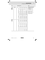
C0007
uSEr
(Forts.)
E4
E3
E2
E1
20
CCW/
QSP
CW/
QSP
TRIP−
Set
JOG1/3
21
CCW/
QSP
CW/
QSP
UP
DOWN
22
CCW/
QSP
CW/
QSP
UP
JOG1/3
23
H/Re
CW/
CCW
UP
DOWN
24
H/Re
PAR
UP
DOWN
25
H/Re
DCB
UP
DOWN
26
H/Re
JOG1/3
UP
DOWN
27
H/Re
TRIP−
Set
UP
DOWN
28
JOG2/3
JOG1/3
PCTRL1
−I−OFF
DFIN1−
ON
29
JOG2/3
DCB
PCTRL1
−I−OFF
DFIN1−
ON
30
JOG2/3
QSP
PCTRL1
−I−OFF
DFIN1−
ON
E4
E3
E2
E1
31
DCB
QSP
PCTRL1
−I−OFF
DFIN1−
ON
32
TRIP−
Set
QSP
PCTRL1
−I−OFF
DFIN1−
ON
33
QSP
PAR
PCTRL1
−I−OFF
DFIN1−
ON
34
CW/
QSP
CCW/
QSP
PCTRL1
−I−OFF
DFIN1−
ON
35
JOG2/3
JOG1/3
PAR
DFIN1−
ON
36
DCB
QSP
PAR
DFIN1−
ON
37
JOG1/3
QSP
PAR
DFIN1−
ON
38
JOG1/3
PAR
TRIP−
Set
DFIN1−
ON
39
JOG2/3
JOG1/3
TRIP−
Set
DFIN1−
ON
40
JOG1/3
QSP
TRIP−
Set
DFIN1−
ON
C0007
uSEr
(Forts.)
EDK82MV371 DE/EN/FR 7.0
l
l
l
l
l
UP/DOWN = Motorpoti−
Funktionen
H/Re = Hand/Remote−
Umschaltung
PCTRL1−I−OFF = I−Anteil
Prozessregler ausschalten
DFIN1−ON = Digitaler
Frequenzeingang 0 ... 10
kHz
PCTRL1−OFF = Prozessregler ausschalten
55
7
Inbetriebnahme
Wichtige Antriebsregler−Codestellen
Code
Nr.
Einstellmöglichkeiten
Bezeichnung
C0007
uSEr
(Forts.)
E4
E3
E2
E1
41
JOG1/3
DCB
TRIP−
Set
DFIN1−
ON
42
QSP
DCB
TRIP−
Set
DFIN1−
ON
43
CW/
CCW
QSP
TRIP−
Set
DFIN1−
ON
44
UP
DOWN
PAR
DFIN1−
ON
45
CW/
CCW
QSP
PAR
DFIN1−
ON
46
H/Re
PAR
QSP
JOG1/3
47
CW/
QSP
CCW/
QSP
H/Re
JOG1/3
48
PCTRL1
− OFF
DCB
PCTRL1
−I−OFF
DFIN1−
ON
49
PCTRL1
− OFF
JOG1/3
QSP
DFIN1−
ON
50
PCTRL1
− OFF
JOG1/3
PCTRL1
−I−OFF
DFIN1−
ON
PAR
PCTRL1
−I−OFF
DFIN1−
ON
DCB
51
255
C0010
uSEr
C0011
uSEr
C0012
uSEr
56
WICHTIG
Lenze Auswahl
In C0410 wurde frei konfiguriert
minimale
Ausgangsfrequenz
0.00
0.00
à 14.5 Hz
maximale
Ausgangsfrequenz
50.00 7.50
à 87 Hz
{0.02
Hz}
Hochlaufzeit
Hauptsollwert
5.00
{0.02
s}
0.00
{0.02
Hz}
Nur Anzeige
C0007 nicht ändern, da Einstellungen in C0410 verlorengehen können
l
C0010 nicht wirksam bei
bipolarer Sollwertvorgabe (−10 V ... + 10 V)
l C0010 begrenzt nur den
Analogeingang 1
l Bei einer max. Ausgangsfrequenz > 50 Hz, muss
die Schaltschwelle der
Auto−DCB in C0019 angehoben werden.
650.00 l Ab Software 3.5: Ist
C0010 > C0011 läuft der
Antrieb bei Reglerfreigabe nicht an.
à Drehzahlstellbereich 1 :
6 für Lenze−Getriebemotoren: Bei Betrieb mit
Lenze−Getriebemotoren
unbedingt einstellen.
650.00
1300.00 Bezug: Frequenzänderung 0
Hz ... C0011
l Zusatzsollwert ð C0220
l Über Digitalsignale aktivierbare Hochlaufzeiten
ð C0101
EDK82MV371 DE/EN/FR 7.0
Inbetriebnahme
7
Wichtige Antriebsregler−Codestellen
Code
Einstellmöglichkeiten
Nr.
Bezeichnung
C0013
Ablaufzeit
Hauptsollwert
5.00
uSEr
C0014
Betriebsart
2
C0015
uSEr
U/f−Nennfrequenz
WICHTIG
Lenze Auswahl
0.00
2
{0.02
s}
1300.00 Bezug: Frequenzänderung
C0011 ... 0 Hz
l Zusatzsollwert ð C0221
l Über Digitalsignale aktivierbare Ablaufzeiten ð
C0103
U/f−Kennliniensteuerung U ~ f
(lineare Kennlinie mit konstanter Umin−Anhebung)
3
U/f−Kennliniensteuerung U ~ f2
(quadratische Kennlinie mit konstanter Umin−Anhebung)
4
Vectorregelung
5
Sensorlose Drehmomentregelung mit Drehzahlklammerung
l Drehmomentsollwert über
C0412/6
l Drehzahlklammerung über
Sollwert 1 (NSET1−N1), wenn
C0412/1 belegt, sonst über
Maximalfrequenz (C0011)
50.00 7.50
{0.02
Hz}
960.00
l
l
Beim erstmaligen Anwählen
die Motordaten eingeben
und mit C0148 die Motorparameter identifizieren
Die Inbetriebnahme ist
sonst nicht möglich
Bei C0014 = 5 muss C0019 =
0 gesetzt werden (Automatische Gleichstrombremse deaktiviert)
l
l
C0016
uSEr
Umin−Anhebung
à
EDK82MV371 DE/EN/FR 7.0
0.00
{0.01
%}
Inbetriebnahme ohne
Identifizierung der Motorparameter möglich
Vorteil der Identifizierung mit C0148:
– Verbesserter Rundlauf
bei kleinen Drehzahlen
– U/f−Nennfrequenz
(C0015) und Schlupf
(C0021) werden berechnet und gespeichert. Sie müssen
nicht eingegeben
werden
C0015 wird bei der Motorparameter−Identifizierung mit C0148 berechnet und gespeichert.
Die Einstellung gilt für
alle zugelassenen Netzspannungen
40.00 à geräteabhängig
Einstellung gilt für alle zugelassenen Netzspannungen
57
7
Inbetriebnahme
Wichtige Antriebsregler−Codestellen
Code
Einstellmöglichkeiten
Nr.
Bezeichnung
C0034*
Bereich Sollwertvorgabe
Standard–
I/O (X3/8)
uSEr
WICHTIG
Lenze Auswahl
Schalterstellung des Funktionsmoduls beachten!
0
0
Spannung unipolar 0 ... 5 V / 0 ...
10 V
Strom 0 ... 20 mA
1
Strom 4 ... 20 mA
Drehrichtungsumkehr nur
mit digitalem Signal möglich.
2
Spannung bipolar −10 V ... +10 V
l
l
3
C0034*
(A)
uSEr
Strom 4 ... 20 mA drahtbruchüberwacht
Bereich Sollwertvorgabe
Application−
I/O
1 X3/1U,
X3/1I
Minimale Ausgangsfrequenz (C0010) nicht
wirksam
Offset und Verstärkung
individuell abgleichen
TRIP Sd5, wenn I < 4 mA
Drehrichtungsumkehr nur
mit digitalem Signal möglich.
Jumperstellung des Funktionsmoduls beachten!
0
2 X3/2U,
X3/2I
0
Spannung unipolar 0 ... 5 V / 0 ...
10 V
1
Spannung bipolar −10 V ... +10 V
2
Strom 0 ... 20 mA
3
Strom 4 ... 20 mA
Drehrichtungsumkehr nur
mit digitalem Signal möglich.
4
Strom 4 ... 20 mA drahtbruchüberwacht
Drehrichtungsumkehr nur
mit digitalem Signal möglich.
TRIP Sd5 bei I < 4 mA
Minimale Ausgangsfrequenz
(C0010) nicht wirksam
650.00 JOG = Festsollwert
Zusätzliche Festsollwerte ð
650.00 C0440
C0037
JOG1
20.00 −650.00
{0.02
Hz}
C0038
JOG2
30.00 −650.00
{0.02
Hz}
C0039
JOG3
40.00 −650.00
{0.02
Hz}
650.00
C0050*
Ausgangsfrequenz
(MCTRL1−NO
UT)
−650.00
{Hz}
650.00 Nur Anzeige: Ausgangsfrequenz ohne Schlupfkompensation
300
{1
rpm}
16000 à geräteabhängig
uSEr
C0087
58
Motor−Bemessungsdrehzahl
à
EDK82MV371 DE/EN/FR 7.0
Inbetriebnahme
7
Wichtige Antriebsregler−Codestellen
Code
Einstellmöglichkeiten
Nr.
Bezeichnung
Lenze Auswahl
C0088
Motor−Bemessungsstrom
à
C0089
Motor−Bemessungsfrequenz
C0090
Motor−Bemessungsspannung
C0091
Motor cos
C0119
Konfiguration Motortemperatur−
Überwachung (PTC−
Eingang) /
Erdschlusserkennung
C0140*
Additiver
Frequenzsollwert
(NSET1−NAD
D)
WICHTIG
650.0 à geräteabhängig
0.0 ... 2.0 x Ausgangsnennstrom des Antriebsreglers
0.0
{0.1 A}
10
{1 Hz}
960
à
50
{1 V}
500 à 230 V bei 230−V−Antriebsreglern,
400 V bei 400−V−Antriebsreglern
à
0.40
50
0
0.00
{0.1}
0
PTC−Eingang
inaktiv
1
PTC−Eingang
aktiv,
TRIP erfolgt
2
PTC−Eingang
aktiv,
Warnung erfolgt
3
PTC−Eingang
inaktiv
4
PTC−Eingang
aktiv,
TRIP erfolgt
5
PTC−Eingang
aktiv,
Warnung erfolgt
−650.00
{0.02
Hz}
1.0 à geräteabhängig
Erdschlusserkennung aktiv
l
l
l
Erdschlusserkennung inaktiv
650.00
l
l
l
l
l
EDK82MV371 DE/EN/FR 7.0
Signalausgabe konfigurieren in C0415
Bei Einsatz mehrerer Parametersätze muss die
Überwachung für jeden
Parametersatz getrennt
eingestellt werden.
Erdschlusserkennung deaktivieren, wenn die Erdschlusserkennung unbeabsichtigt ausgelöst
wird.
Bei aktivierter Erdschlusserkennung läuft
der Motor nach Reglerfreigabe um ca. 40 ms
verzögert an.
Vorgabe über Funktion
des Keypad oder Parameterkanal
Wirkt additiv auf den
Hauptsollwert
Wert wird bei Netzschalten oder bei Abziehen
des Keypad gespeichert
C0140 wird nur beim
Parametersatztransfer
mit GDC übertragen
(nicht mit Keypad)
59
7
Inbetriebnahme
Wichtige Antriebsregler−Codestellen
Code
Einstellmöglichkeiten
Nr.
Bezeichnung
C0148*
Motordaten
identifizieren
#
C0517*
WICHTIG
Lenze Auswahl
0
0
Bereit
1
Identifizierung starten
l U/f−Nennfrequenz (C0015),
Schlupfkompensation
(C0021) und Motor−Ständerinduktivität (C0092) werden
berechnet und gespeichert
l Der Motor−Ständerwiderstand (C0084) = Gesamtwiderstand von Motorleitung
und Motor wird gemessen
und gespeichert
Nur bei kaltem Motor durchführen!
1. Regler sperren, warten
bis Antrieb steht
2. In C0087, C0088, C0089,
C0090, C0091 die korrekten Werte vom Motor−
Typenschild eingeben
3. C0148 = 1 setzen, mit
bestätigen
4. Regler freigeben:
Die Identifizierung
– startet, erlischt
– der Motor "pfeift"
leise, dreht sich aber
nicht!
– dauert ca. 30 s
– ist beendet, wenn wieder leuchtet
5. Regler sperren
l
User−Menü
1 Speicher 1
50
C0050
Ausgangsfrequenz
(MCTRL1−NOUT)
2 Speicher 2
34
C0034
Bereich analoge Sollwertvorgabe
3 Speicher 3
7
C0007
Feste Konfiguration digitale Eingangssignale
4 Speicher 4
10
C0010
Minimale Ausgangsfrequenz
5 Speicher 5
11
C0011
Maximale Ausgangsfrequenz
6 Speicher 6
12
C0012
Hochlaufzeit Hauptsollwert
7 Speicher 7
13
C0013
Ablaufzeit Hauptsollwert
8 Speicher 8
15
C0015
U/f−Nennfrequenz
9 Speicher 9
16
C0016
Umin−Anhebung
10 Speicher 10
2
C0002
Parametersatz−Transfer
l
l
l
Nach Netzschalten oder
in der Funktion wird
der Code aus C0517/1
angezeigt.
Das User−Menü enthält
in der Lenze−Einstellung
die wichtigsten Codes für
die Inbetriebnahme der
Betriebsart "U/f−Kennliniensteuerung mit linearer Kennlinie"
Bei aktivem Passwortschutz sind nur die in
C0517 eingetragenen
Codes frei zugänglich
Wenn weniger als 10 Codes benötigt werden,
den nicht verwendeten
Speicherplätzen den
Wert "0" (Null) zuweisen.
Bitte beachten Sie dabei,
dass die Software die
Codestelle C0050 automatisch einem nicht verwendeten Speicherplatz
zuweist, wenn diese
nicht explizit einem anderen Speicherplatz zugewiesen wurde.
Mögliche Eingaben für C0517
xxxx
60
Alle Code−Nummern außer den
Codes, die mit "(A)" gekennzeichnet sind.
Syntax:
Codes: C0517/x = cccc
Subcodes: C0517/x = cccc.ss
EDK82MV371 DE/EN/FR 7.0
Inbetriebnahme
7
Wichtige Antriebsregler−Codestellen
Code
Einstellmöglichkeiten
Nr.
Bezeichnung
C0608*
Lüfterüberwachung
WICHTIG
Lenze Auswahl
EDK82MV371 DE/EN/FR 7.0
0
0
inaktiv
1
TRIP−Fehlermeldung
2
Warnung
8200 motec 3 ... 7.5 kW:
Funktion unbedingt bei der
Inbetriebnahme aktivieren
(empfohlen: C0608 = 1)! Der
Antriebsregler kann sonst
durch Überhitzung zerstört
werden.
Alle anderen Antriebsregler:
Unbedingt C0608 = 0 einstellen.
61
8
Fehlersuche und Störungsbeseitigung
Fehlersuche
8
Fehlersuche und Störungsbeseitigung
Fehlersuche
Fehlverhalten
Ursache
Abhilfe
Motor dreht nicht
Zwischenkreisspannung zu niedrig
(Rote LED blinkt im 0.4 s Takt;
Anzeige Keypad: LU)
Netzspannung prüfen
Antriebsregler gesperrt
(Grüne LED blinkt, Anzeige Keypad:
)
Reglersperre aufheben, Reglersperre kann über mehrere
Quellen gesetzt sein
Automatischer Start gesperrt (C0142
= 0 oder 2)
LOW−HIGH−Flanke an X3/28
Evtl. Startbedingung (C0142)
korrigieren
Gleichstrombremsung (DCB) aktiv
Gleichstrombremse deaktivieren
Mechanische Motorbremse ist nicht
gelöst
Mechanische Motorbremse
manuell oder elektrisch lösen
Quickstop (QSP) aktiv (Anzeige Keypad: )
Quickstop aufheben
Sollwert = 0
Sollwert vorgeben
JOG−Sollwert aktiviert und JOG−Frequenz = 0
JOG−Sollwert vorgeben
(C0037 ... C0039)
Störung aktiv
Störung beseitigen
Falscher Parametersatz aktiv
Auf richtigen Parametersatz
über Klemme umschalten
Betriebsart C0014 = −4−, −5− eingestellt, aber keine Motorparameter−
Identifizierung durchgeführt
Motorparameter identifizieren (C0148)
Belegung mehrerer, sich ausschließender Funktionen mit einer Signalquelle in C0410
Konfiguration in C0410 korrigieren
Interne Spannungsquelle X3/20 verKlemmen brücken
wendet bei den Funktionsmodulen
Standard−I/O, INTERBUS, PROFIBUS−
DP oder LECOM−B (RS485):
Brücke zwischen X3/7 und X3/39 fehlt
Motor dreht ungleichmäßig
Motor nimmt zu viel Strom auf
62
Motorleitung defekt
Motorleitung prüfen
Maximalstrom zu gering eingestellt
(C0022, C0023)
Einstellungen an die Anwendung anpassen
Motor unter− bzw. übererregt
Parametrierung kontrollieren
(C0015, C0016, C0014)
C0084, C0087, C0088, C0089, C0090,
C0091 und/oder C0092 nicht an die
Motordaten angepasst
Manuell anpassen oder Motorparameter identifizieren
(C0148); Vectorregelung optimieren
Einstellung von C0016 zu groß gewählt
Einstellung korrigieren
Einstellung von C0015 zu klein gewählt
Einstellung korrigieren
EDK82MV371 DE/EN/FR 7.0
Fehlersuche und Störungsbeseitigung
8
Fehlersuche
Fehlverhalten
Ursache
Abhilfe
C0084, C0087, C0088, C0089, C0090,
C0091 und/oder C0092 nicht an die
Motordaten angepasst
Manuell anpassen oder Motorparameter identifizieren
(C0148); Vectorregelung optimieren
Motor dreht, Sollwerte sind 0"
Mit der Funktion des Keypad
wurde ein Sollwert vorgegeben
Sollwert auf "0" setzen mit
C0140 = 0
Motorparameter−Identifizierung
bricht ab mit Fehler LP1
Motor ist zu klein im Verhältnis zur
Geräte−Nennleistung
Gleichstrombremse (DCB) über
Klemme aktiv
Antriebsverhalten bei Vectorregelung nicht zufriedenstellend
verschiedene
Vectorregelung optimieren
Einbruch des Drehmoments im
Feldschwächbereich
verschiedene
Rücksprache mit Lenze
Kippen des Motors bei Betrieb
im Feldschwächbereich
EDK82MV371 DE/EN/FR 7.0
63
8
Fehlersuche und Störungsbeseitigung
Störungsmeldungen
Störungsmeldungen
LED’s am Antriebsregler (Statusanzeige)
LED
rot
grün
Betriebszustand
aus
ein
Antriebsregler freigegeben
ein
ein
Netz eingeschaltet und automatischer
Start gesperrt
aus
blinkt langsam
Antriebsregler gesperrt
aus
blinkt schnell
Motorparameteridentifizierung wird
durchgeführt
blinkt schnell
aus
Unterspannungsabschaltung
blinkt
langsam
aus
Störung aktiv, Kontrolle in C0161
2
1
v t
3
20
X3
28
m
Hz V A
%sh Ω°C
rpm
u s
r
8
8888 888
88888
q
Hi
Lo
OFF
1
01 61 000
m n op
q r
880Hr
4
d c b e a
j g f k i h PS
Hi
Lo
d c b e a
j g f k i h PS
m n op
z
w x
y
5
m
Hz V A
%sh Ω°C
rpm
6
ON
82mot355
So setzen Sie den Antriebsregler zurück, wenn eine Störung auftritt (TRIP−Reset):
1. Während des Betriebs Keypad auf die AIF−Schnittstelle aufstecken.
2. Fehlermeldung der Keypad−Anzeige ablesen und notieren.
3. Antriebsregler sperren.
4. Antriebsregler vom Netz trennen.
5. Fehleranalyse durchführen und Fehler beseitigen.
6. Antriebsregler erneut einschalten.
64
EDK82MV371 DE/EN/FR 7.0
Fehlersuche und Störungsbeseitigung
8
Störungsmeldungen
Keypad
noer
ccr
$
PC 1)
Störung
Ursache
Abhilfe
0
keine Störung
−
−
71
Systemstörung
starke Störeinkopplungen
auf Steuerleitungen
Steuerleitung abgeschirmt verlegen
Masse− oder Erdschleifen in
der Verdrahtung
ce0
$
61
Kommunikationsfehler an AIF
(konfigurierbar
in C0126)
Übertragung von Steuerbefehlen über AIF ist gestört
Kommunikationsmodul fest in
das Handterminal stecken
ce1
$
62
Kommunikationsfehler an
CAN−IN1 bei
Sync−Steuerung
CAN−IN1−Objekt empfängt
fehlerhafte Daten oder
Kommunikation ist unterbrochen
l
Kommunikationsfehler an
CAN−IN2
CAN−IN2−Objekt empfängt
fehlerhafte Daten oder
Kommunikation ist unterbrochen
l
Kommunikationsfehler an
CAN−IN1 bei Ereignis− bzw.
Zeitsteuerung
CAN−IN1−Objekt empfängt
fehlerhafte Daten oder
Kommunikation ist unterbrochen
l
BUS−OFF
(viele Kommunikationsfehler
aufgetreten)
Antriebsregler hat zu viele
fehlerhafte Telegramme
über Systembus empfangen
und sich vom Bus abgekoppelt
l
ce2
$
ce3
$
ce4
$
63
64
65
l
l
l
l
l
l
l
l
l
ce5
$
66
CAN Time−Out
(konfigurierbar
in C0126)
EDK82MV371 DE/EN/FR 7.0
Steckverbindung Busmodul ó FIF prüfen
Sender überprüfen
evtl. Überwachungszeit in
C0357/1 erhöhen
Steckverbindung Busmodul ó FIF prüfen
Sender überprüfen
evtl. Überwachungszeit in
C0357/2 erhöhen
Steckverbindung Busmodul
ó FIF prüfen
Sender überprüfen
evtl. Überwachungszeit in
C0357/3 erhöhen
Prüfen, ob Busabschluss vorhanden
Schirmauflage der Leitungen prüfen
PE−Anbindung prüfen
Busbelastung prüfen, ggf.
Baud−Rate reduzieren
Bei Fernparametrierung
über Systembus (C0370):
Slave antwortet nicht. Kommunikations−Überwachungszeit überschritten
l
Bei Betrieb mit Application−
I/O:
Parametersatz−Umschaltung falsch parametriert
In allen Parametersätzen muss
das Signal "Parametersatz umschalten" (C0410/13, C0410/14)
mit der gleichen Quelle verknüpft sein
Bei Betrieb mit Modul auf
FIF:
Interner Fehler
Rücksprache mit Lenze erforderlich
l
Verdrahtung des Systembus
prüfen
Systembus−Konfiguration
prüfen
65
8
Fehlersuche und Störungsbeseitigung
Störungsmeldungen
Keypad
PC 1)
Störung
Ursache
Abhilfe
Funktionsmodul CAN Controller meldet ZuSystembus (CAN) stand "Warnung" oder
auf FIF ist im Zu- "BUS−OFF"
stand "Warnung" oder
"BUS−OFF"
(konfigurierbar
in C0126)
l
Kommunikationsfehler bei
Fernparametrierung über
Systembus
(C0370)
(konfigurierbar
in C0126)
Teilnehmer antwortet nicht
oder ist nicht vorhanden
l
Bei Betrieb mit Application−
I/O:
Parametersatz−Umschaltung falsch parametriert
In allen Parametersätzen muss
das Signal "Parametersatz umschalten" (C0410/13, C0410/14)
mit der gleichen Quelle verknüpft sein
91
Externe Störung
(TRIP−SET)
Ein mit der Funktion TRIP−
Set belegtes digitales Signal
ist aktiviert
Externen Geber überprüfen
−
Kommunikationsabbruch zwischen Keypad
und Grundgerät
verschiedene
Rücksprache mit Lenze
FAn1
$
95
Lüfter defekt
Lüfter tauschen
FAn1
−
Lüfterstörung
(nur 8200 motec
3 ... 7.5 kW)
TRIP oder Warnung konfigurierbar in C0608
Lüfter nicht angeschlossen
Lüfter anschließen
Verdrahtung prüfen
H05
$
id1
$
105
Interne Störung
Rücksprache mit Lenze
140
Fehlerhafte PaMotor nicht angeschlossen
rameter−Identifizierung
Motor anschließen
LP1
$
32
Fehler in Motorphase
(Anzeige, wenn
C0597 = 1)
LP1
182
ce6
$
ce7
$
EEr
$
ErP0
...
ErP19
$
66
67
68
l
l
l
l
l
l
l
l
Ausfall einer/mehrerer
Motorphasen
Zu geringer Motorstrom
Fehler in Motorphase
(Anzeige, wenn
C0597 = 2)
l
l
l
Prüfen, ob Busabschluss vorhanden
Schirmauflage der Leitungen prüfen
PE−Anbindung prüfen
Busbelastung prüfen, ggf.
Baud−Rate reduzieren
Prüfen, ob Busabschluss vorhanden
Schirmauflage der Leitungen prüfen
PE−Anbindung prüfen
Busbelastung prüfen, ggf.
Baud−Rate reduzieren
Motorzuleitungen prüfen
Umin−Anhebung prüfen,
Motor mit entsprechender
Leistung anschließen oder
mit C0599 Motor anpassen
EDK82MV371 DE/EN/FR 7.0
Fehlersuche und Störungsbeseitigung
8
Störungsmeldungen
Keypad
LU
PC 1)
−
Störung
Ursache
Abhilfe
Zwischenkreis−
Unterspannung
Netzspannung zu niedrig
Netzspannung prüfen
Spannung im DC−Verbund
zu niedrig
Versorgungsmodul prüfen
400 V−Antriebsregler an 240 Antriebsregler an richtige NetzV−Netz angeschlossen
spannung anschließen
OC1
$
OC2
$
11
Kurzschluss
Kurzschluss
l
l
12
Erdschluss
Kurzschlussursache suchen;
Motorleitung prüfen
Bremswiderstand und Leitung zum Bremswiderstand
prüfen
Kapazitiver Ladestrom der
Motorleitung zu hoch
Kürzere/kapazitätsärmere Motorleitung verwenden
Eine Motorphase hat Erdkontakt
Motor überprüfen; Motorleitung prüfen
Kapazitiver Ladestrom der
Motorleitung zu hoch
Kürzere/kapazitätsärmere Motorleitung verwenden
Erdschlusserkennung zu Prüfzwecken deaktivieren
OC3
$
13
Zu kurz eingestellte Hochlaufzeit (C0012)
l
Defekte Motorleitung
Verdrahtung überprüfen
Windungsschluss im Motor
Motor überprüfen
Überlast Antriebsregler im
Ablauf
Zu kurz eingestellte Ablaufzeit (C0013)
l
Antriebsauslegung prüfen
Überlast Antriebsregler im
Hochlauf oder
Kurzschluss
OC4
$
14
OC5
$
15
Überlast Antriebsregler im
stationären Betrieb
Häufige und zu lange Überlast
OC6
$
16
Überlast Motor
(I2 x t − Überlast)
Motor thermisch überlastet
durch z. B.
l
l
Hochlaufzeit verlängern
Antriebsauslegung prüfen
Ablaufzeit verlängern
Auslegung des externen
Bremswiderstandes prüfen
l
unzulässigen Dauerstrom
l
Antriebsauslegung prüfen
l
häufige oder zu lange
Beschleunigungsvorgänge
l
Einstellung von C0120 prüfen
OH
$
50
Kühlkörpertemperatur > +85 °C
Umgebungstemperatur zu
hoch
Antriebsregler abkühlen lassen
und für eine bessere Belüftung
sorgen
OH
%
OH
%
−
Kühlkörpertemperatur > +80 °C
Kühlkörper stark verschmutzt
Kühlkörper reinigen
−
Kühlkörpertemperatur > +80 °C
Unzulässig hohe Ströme
oder häufige und zu lange
Beschleunigungsvorgänge
l
EDK82MV371 DE/EN/FR 7.0
l
Antriebsauslegung überprüfen
Last überprüfen, ggf.
schwergängige, defekte Lager auswechseln
67
8
Fehlersuche und Störungsbeseitigung
Störungsmeldungen
Keypad
OH3
$
OH4
$
PC 1)
53
54
Störung
Ursache
Abhilfe
PTC−Überwachung (TRIP)
(Anzeige, wenn
C0119 = 1 oder
4)
Motor zu warm durch unzulässig hohe Ströme oder
häufige und zu lange Beschleunigungsvorgänge
Antriebsauslegung prüfen
Kein PTC angeschlossen
PTC anschließen oder Überwachung abschalten
Übertemperatur
Antriebsregler
Innenraum des Antriebsreglers zu warm
l
l
l
OH51
OU
OUE
$
203
−
22
PTC−Überwachung
(Anzeige, wenn
C0119 = 2 oder
5)
Motor zu warm durch unzulässig hohe Ströme oder
häufige und zu lange Beschleunigungsvorgänge
Antriebsauslegung prüfen
Kein PTC angeschlossen
PTC anschließen oder Überwachung abschalten
Zwischenkreis−
Überspannung
(Meldung oder
TRIP konfigurierbar in C0310)
Netzspannung zu hoch
Versorgungsspannung kontrollieren
Bremsbetrieb
l
l
Schleichender Erdschluss
auf der Motorseite
Pr
$
75
Parameter−Über- Alle Parametersätze sind detragung mit dem fekt
Keypad fehlerhaft
Pr1
$
72
PAR1 mit dem
Keypad falsch
übertragen
Parametersatz 1 ist defekt
Pr2
$
73
PAR2 mit dem
Keypad falsch
übertragen
Parametersatz 2 ist defekt
Pr3
$
77
PAR3 mit dem
Keypad falsch
übertragen
Parametersatz 3 ist defekt
Pr4
$
78
PAR4 mit dem
Keypad falsch
übertragen
Parametersatz 4 ist defekt
68
Belastung des Antriebsreglers senken
Kühlung verbessern
Lüfter im Antriebsregler prüfen
Ablaufzeiten verlängern
Bei Betrieb mit externem
Bremswiderstand:
– Dimensionierung, Anschluss und Zuleitung des
Bremswiderstandes prüfen
– Ablaufzeiten verlängern
Motorzuleitung und Motor auf
Erdschluss prüfen (Motor vom
Umrichter trennen)
Vor Reglerfreigabe unbedingt
den Datentransfer wiederholen
oder die Lenze−Einstellung laden
EDK82MV371 DE/EN/FR 7.0
Fehlersuche und Störungsbeseitigung
8
Störungsmeldungen
Keypad
PC 1)
Störung
Ursache
Abhilfe
Pr5
$
79
Interne Störung
EEPROM defekt
Rücksprache mit Lenze
Pt5
$
81
Zeitfehler bei Pa- Datenfluss vom Keypad oder Vor Reglerfreigabe unbedingt
rametersatz−
vom PC unterbrochen, z. B.
den Datentransfer wiederholen
Transfer
Keypad wurde während der oder Lenze−Einstellung laden.
Datenübertragung abgezogen
rSt
$
sd5
$
sd7
$
76
Fehler bei Auto−
TRIP−Reset
85
Drahtbruch Ana- Strom am Analogeingang
logeingang 1
< 4 mA bei Sollwertbereich
4 ... 20 mA
Drahtbruch Analogeingang 2
1)
87
Mehr als 8 Fehlermeldungen in 10 Minuten
Abhängig von der Fehlermeldung
Stromkreis am Analogeingang
schließen
LECOM−Fehlernummer, Anzeige im Parametrierprogramm Global Drive Control (GDC)
EDK82MV371 DE/EN/FR 7.0
69
Type code
E82MV xxx
−
x
B
xxx
xx
xx
Type
Power
(e.g. 371 = 37 ´ 101 W = 0.37 kW)
(e.g. 751 = 75 ´ 101 W = 0.75 kW)
(e.g. 222 = 22 ´ 102 W = 2.2 kW)
(e.g. 752 = 75 ´ 102 W = 7.5 kW)
0.25 kW / 0.37 kW
Voltage class
2 = 230 V
Device generation
Version, variant
001 = standard version, coated
151 = heatsink powder−coated
Hardware version
Software version
Tip!
Information and auxiliary devices related to the Lenze products can be found
in the download area at
http://www.Lenze.com
70
EDK82MV371 DE/EN/FR 7.0
Commissioning of 8200 motec without function module
l
The 8200 motec can only be used when the FIF
cover is mounted! (delivery status).
– If the FIF cover is not mounted, the 8200 motec
is inhibited (keypad: ).
Since the 8200 motec without a function module
does not provide any control terminals, starting and
stopping during operation is also possible by
switching the mains.
The function saves the setpoint at the time the
operation is interrupted when switching the mains
or in case of mains failures. The drive restarts
automatically as soon as the mains recovers!
If the drive does not start at step ( is not off),
press to enable the 8200 motec.
l
l
l
E82ZWLxxx
A
8200mot041
L1 / L2 / L3 / N / PE
E82ZBB
a e b c d
8 SP h i k f g j
m
888 8888porn q
88888
iH
oL
d c
j
0140
5000
z
w x
y
vt
s u
tv
2
1
z
x w
y
AIF
2V 2 U 2 W
1 W 1V 1 U
EP
w
3
Hz
u s
m
A V zH
C°Ω hs %
mpr
j
z 0....+50 Hz
y 0....- 50 Hz
8200mot042
Step
Comment
Connect diagnosis terminal
Diagnosis terminal and connecting cable are not included in the
(contains keypad) with motec. scope of supply.
Put the plug of the
connecting cable into the AIF
interface on the motec.
Connect mains voltage.
The controller is ready for operation after approx. 1 second.
Keypad: Select setpoint via the Activate Automatic start is possible!
function.
CW rotation
CCW rotation
goes off. The drive is running now.
Display indicates output frequency.
Faults during commissioning or operation? chapter 8
0Fig. 0Tab. 0
EDK82MV371 DE/EN/FR 7.0
71
i
Contents
1 About this documentation . . . . . . . . . . . . . . . . . . . . . . . . . . . . . . . . . . . . . . . . . . .
Conventions used . . . . . . . . . . . . . . . . . . . . . . . . . . . . . . . . . . . . . . . . . . . . . . . . . .
Notes used . . . . . . . . . . . . . . . . . . . . . . . . . . . . . . . . . . . . . . . . . . . . . . . . . . . . . . . .
Application as directed . . . . . . . . . . . . . . . . . . . . . . . . . . . . . . . . . . . . . . . . . . . . .
73
73
74
75
2 Safety instructions . . . . . . . . . . . . . . . . . . . . . . . . . . . . . . . . . . . . . . . . . . . . . . . . .
General safety information . . . . . . . . . . . . . . . . . . . . . . . . . . . . . . . . . . . . . . . . . .
General safety and application instructions for Lenze motors . . . . . . . . . . . . . . .
Residual hazards . . . . . . . . . . . . . . . . . . . . . . . . . . . . . . . . . . . . . . . . . . . . . . . . . . .
76
76
79
82
3 Technical data . . . . . . . . . . . . . . . . . . . . . . . . . . . . . . . . . . . . . . . . . . . . . . . . . . . . .
General data and operating conditions . . . . . . . . . . . . . . . . . . . . . . . . . . . . . . . .
Operation with rated power (normal operation) . . . . . . . . . . . . . . . . . . . . . . . . .
Dimensions . . . . . . . . . . . . . . . . . . . . . . . . . . . . . . . . . . . . . . . . . . . . . . . . . . . . . . .
Mechanical design . . . . . . . . . . . . . . . . . . . . . . . . . . . . . . . . . . . . . . . . . . . . . . . . . .
84
84
87
88
88
4 Mechanical installation . . . . . . . . . . . . . . . . . . . . . . . . . . . . . . . . . . . . . . . . . . . . . .
motec with motor or geared motor . . . . . . . . . . . . . . . . . . . . . . . . . . . . . . . . . . . .
Wall mounting . . . . . . . . . . . . . . . . . . . . . . . . . . . . . . . . . . . . . . . . . . . . . . . . . . . . .
Motor mounting . . . . . . . . . . . . . . . . . . . . . . . . . . . . . . . . . . . . . . . . . . . . . . . . . . .
89
89
92
97
5 Electrical installation . . . . . . . . . . . . . . . . . . . . . . . . . . . . . . . . . . . . . . . . . . . . . . . .
Mains connection . . . . . . . . . . . . . . . . . . . . . . . . . . . . . . . . . . . . . . . . . . . . . . . . . .
Fuses and cable cross−sections . . . . . . . . . . . . . . . . . . . . . . . . . . . . . . . . . . . . . . . .
Dimensioning of mains contactors . . . . . . . . . . . . . . . . . . . . . . . . . . . . . . . . . . . .
Relay output connection . . . . . . . . . . . . . . . . . . . . . . . . . . . . . . . . . . . . . . . . . . . . .
Mounting of function module (option) . . . . . . . . . . . . . . . . . . . . . . . . . . . . . . . . .
101
101
102
102
103
104
6 Final works . . . . . . . . . . . . . . . . . . . . . . . . . . . . . . . . . . . . . . . . . . . . . . . . . . . . . . . .
motec assembly . . . . . . . . . . . . . . . . . . . . . . . . . . . . . . . . . . . . . . . . . . . . . . . . . . . .
105
105
7 Commissioning . . . . . . . . . . . . . . . . . . . . . . . . . . . . . . . . . . . . . . . . . . . . . . . . . . . .
Before switching on . . . . . . . . . . . . . . . . . . . . . . . . . . . . . . . . . . . . . . . . . . . . . . . .
Selection of the operating mode . . . . . . . . . . . . . . . . . . . . . . . . . . . . . . . . . . . . . .
Parameter setting with the E82ZBB diagnosis terminal . . . . . . . . . . . . . . . . . . . .
Linear V/f−characteristic control . . . . . . . . . . . . . . . . . . . . . . . . . . . . . . . . . . . . . . .
Vector control . . . . . . . . . . . . . . . . . . . . . . . . . . . . . . . . . . . . . . . . . . . . . . . . . . . . .
Important controller codes . . . . . . . . . . . . . . . . . . . . . . . . . . . . . . . . . . . . . . . . . . .
107
107
108
110
111
113
117
8 Troubleshooting and fault elimination . . . . . . . . . . . . . . . . . . . . . . . . . . . . . . . . .
Troubleshooting . . . . . . . . . . . . . . . . . . . . . . . . . . . . . . . . . . . . . . . . . . . . . . . . . . .
Fault messages . . . . . . . . . . . . . . . . . . . . . . . . . . . . . . . . . . . . . . . . . . . . . . . . . . . .
LEDs on the controller (status display) . . . . . . . . . . . . . . . . . . . . . . . . . . . . . . . . . .
129
129
131
131
72
EDK82MV371 DE/EN/FR 7.0
About this documentation
1
Conventions used
1
About this documentation
Validity information
These instructions are valid for
ƒ E82MV251 frequency inverter
ƒ E82MV371 frequency inverter
Target group
This documentation is directed at qualified skilled personnel according to IEC 60364.
Qualified skilled personnel are persons who have the required qualifications to carry out
all activities involved in installing, mounting, commissioning, and operating the product.
Conventions used
This documentation uses the following conventions to distinguish between different
types of information:
Spelling of numbers
Decimal separator
Point
In general, the decimal point is used.
For instance: 1234.56
Warnings
UL warnings
UR warnings
Are only given in English.
Icons
Page reference
Reference to another page with
additional information
For instance: 16 = see page 16
Documentation reference
Reference to another documentation
with additional information
For example: EDKxxx = see
documentation EDKxxx
EDK82MV371 DE/EN/FR 7.0
73
1
About this documentation
Notes used
Notes used
The following pictographs and signal words are used in this documentation to indicate
dangers and important information:
Safety instructions
Structure of safety instructions:
Danger!
(characterises the type and severity of danger)
Note
(describes the danger and gives information about how to prevent
dangerous situations)
Pictograph and signal word
Meaning
Danger!
Danger of personal injury through dangerous electrical
voltage.
Reference to an imminent danger that may result in death
or serious personal injury if the corresponding measures are
not taken.
Danger!
Danger of personal injury through a general source of
danger.
Reference to an imminent danger that may result in death
or serious personal injury if the corresponding measures are
not taken.
Stop!
Danger of property damage.
Reference to a possible danger that may result in property
damage if the corresponding measures are not taken.
Application notes
Pictograph and signal word
74
Meaning
Note!
Important note to ensure troublefree operation
Tip!
Useful tip for simple handling
Reference to another documentation
EDK82MV371 DE/EN/FR 7.0
About this documentation
1
Application as directed
Special safety instructions and application notes for UL and UR
Pictograph and signal word
Meaning
Warnings!
Safety or application note for the operation of a
UL−approved device in UL−approved systems.
Possibly the drive system is not operated in compliance with
UL if the corresponding measures are not taken.
Warnings!
Safety or application note for the operation of a
UR−approved device in UL−approved systems.
Possibly the drive system is not operated in compliance with
UL if the corresponding measures are not taken.
Application as directed
8200 motec frequency inverter and accessories
ƒ are components
– for open and closed loop control of variable speed drives with asynchronous
standard motors, reluctance motors, PM synchronous motors with asynchronous
damping cage.
– for installation into a machine.
– used for assembly together with other components to form a machine.
ƒ must only be operated under the conditions prescribed in this documentation.
ƒ comply with the requirements of the EC LowVoltage Directive.
ƒ are not machines for the purpose of the EC Machinery Directive.
ƒ are not to be used as domestic appliances, but only for industrial purposes
according to EN 61000−3−2.
The drive system (frequency inverters and drive) meet the EC Electromagnetic
Compatibility Directive if they are installed according to the guidelines of CEtypical drive
systems.
Any other use shall be deemed as inappropriate!
EDK82MV371 DE/EN/FR 7.0
75
2
Safety instructions
General safety information
2
Safety instructions
General safety information
Scope
The following general safety instructions apply to all Lenze drive and automation
components.
The product−specific safety and application notes given in this documentation must be
observed!
Notes regarding the use of the controllers in UL−approved systems can be found in the
separately enclosed documentation.
For your own safety
Danger!
Disregarding the following basic safety measures may lead to severe
personal injury and damage to material assets!
ƒ Lenze drive and automation components ...
... must only be used for the intended purpose.
... must never be operated if damaged.
... must never be subjected to technical modifications.
... must never be operated unless completely assembled.
... must never be operated without the covers/guards.
... can − depending on their degree of protection − have live, movable or rotating parts
during or after operation. Surfaces can be hot.
ƒ All specifications of the corresponding enclosed documentation must be observed.
This is vital for a safe and trouble−free operation and for achieving the specified
product features.
The procedural notes and circuit details provided in this document are proposals
which the user must check for suitability for his application. The manufacturer does
not accept any liability for the suitability of the specified procedures and circuit
proposals.
ƒ Only qualified skilled personnel are permitted to work with or on Lenze drive and
automation components.
According to IEC 60364 or CENELEC HD 384, these are persons ...
... who are familiar with the installation, assembly, commissioning and operation of
the product,
... possess the appropriate qualifications for their work,
... and are acquainted with and can apply all the accident prevent regulations,
directives and laws applicable at the place of use.
Transport, storage
ƒ Transport and storage in a dry, low−vibration environment without aggressive
atmosphere; preferably in the packaging provided by the manufacturer.
– Protect against dust and shocks.
– Comply with climatic conditions according to the technical data.
76
EDK82MV371 DE/EN/FR 7.0
Safety instructions
2
General safety information
Mechanical installation
ƒ Install the product according to the regulations of the corresponding
documentation. In particular observe the section "Operating conditions" in the
chapter "Technical data".
ƒ Provide for a careful handling and avoid mechanical overload. During handling
neither bend components, nor change the insulation distances.
ƒ The product contains electrostatic sensitive devices which can easily be damaged
by short circuit or static discharge (ESD). Thus, electronic components and contacts
must not be touched unless ESD measures are taken beforehand.
Electrical installation
ƒ Carry out the electrical installation according to the relevant regulations (e. g. cable
cross−sections, fusing, connection to the PE conductor). Additional notes are
included in the documentation.
ƒ When working on live products, observe the applicable national regulations for the
prevention of accidents (e.g. BGV 3).
ƒ The Instructions contain notes concerning wiring according to EMC regulations
(shielding, earthing, filters and cable routing). The compliance with limit values
required by the EMC legislation is the responsibility of the manufacturer of the
machine or system.
Warning: Controllers are products with restricted availability according to EN
61800−3. These products can cause interferences in residential premises. If controllers
are used in residential premises, corresponding measures are required.
ƒ Only plug in or remove pluggable terminals in the deenergised state!
EDK82MV371 DE/EN/FR 7.0
77
2
Safety instructions
General safety information
Commissioning
ƒ If required, you have to equip the system with additional monitoring and
protective devices in accordance with the respective valid safety regulations (e. g.
law on technical equipment, regulations for the prevention of accidents).
ƒ Before commissioning remove transport locking devices and keep them for later
transports.
Operation
ƒ Keep all protective covers and doors closed during operation.
Maintenance and servicing
ƒ The components are maintenance−free if the required operating conditions are
observed.
ƒ If the cooling air is polluted, the cooling surfaces may be contaminated or the air
vents may be blocked. Under these operating conditions, the cooling surfaces and
air vents must be cleaned at regular intervals. Never use sharp objects for this
purpose!
ƒ After the system has been disconnected from the supply voltage, live components
and power connections must not be touched immediately because capacitors may
be charged. Please observe the corresponding notes on the device.
Disposal
ƒ Recycle metals and plastic materials. Ensure professional disposal of assembled
PCBs.
78
EDK82MV371 DE/EN/FR 7.0
Safety instructions
2
General safety and application instructions for Lenze motors
General safety and application instructions for Lenze motors
(According to: Low−Voltage Directive 2006/95/EC)
General
Low−voltage machines have dangerous, live and rotating parts as well as possibly hot
surfaces.
Synchronous machines induce voltages at open terminals during operation.
All operations serving transport, connection, commissioning and maintenance are to be
carried out by skilled, responsible technical personnel (observe EN 50110−1 (VDE 0105−1)
and IEC 60364). Improper handling can cause severe injuries or damages.
Lowvoltage machines may only be operated under the conditions that are indicated in the
section "Application as directed".
The conditions at the place of installation must comply with the data given on the
nameplate and in the documentation.
Application as directed
Lowvoltage machines are intended for commercial installations. They comply with the
harmonised standards of the series IEC/EN60034 (VDE 0530). Their use in potentially
explosive atmospheres is prohibited unless they are expressly intended for such use
(follow additional instructions).
Lowvoltage machines are components for installation into machines as defined in the
Machinery Directive 2006/42/EC. Commissioning is prohibited until the conformity of the
end product with this directive has been established (follow i. a. EN 60204−1).
Lowvoltage machines with IP23 protection or less are only intended for outdoor use when
applying special protective features.
The integrated brakes must not be used as safety brakes. It cannot be ruled out that factors
which cannot be influenced, such as oil ingress due to a defective Aside shaft seal, cause
a brake torque reduction.
Transport, storage
Damages must be reported immediately upon receipt to the forwarder; if required,
commissioning must be excluded. Tighten screwedin ring bolts before transport. They are
designed for the weight of the lowvoltage machines, do not apply extra loads. If necessary,
use suitable and adequately dimensioned means of transport (e. g. rope guides).
Remove transport locking devices before commissioning. Reuse them for further
transport. When storing lowvoltage machines, ensure a dry, dustfree and lowvibration
(veff £ 0.2 mm/s) environment (bearing damage while being stored).
EDK82MV371 DE/EN/FR 7.0
79
2
Safety instructions
General safety and application instructions for Lenze motors
Installation
Ensure an even surface, solid foot/flange mounting and exact alignment if a direct clutch
is connected. Avoid resonances with the rotational frequency and double mains frequency
which may be caused by the assembly. Turn rotor by hand, listen for unusual slipping
noises. Check the direction of rotation when the clutch is not active (observe section
"Electrical connection").
Use appropriate means to mount or remove belt pulleys and clutches (heating) and cover
them with a touch guard. Avoid impermissible belt tensions.
The machines are halfkey balanced. The clutch must be halfkey balanced, too. The visible
jutting out part of the key must be removed.
If required, provide pipe connections. Designs with shaft end at bottom must be protected
with a cover which prevents the ingress of foreign particles into the fan. Free circulation
of the cooling air must be ensured. The exhaust air also the exhaust air of other machines
next to the drive system must not be taken in immediately.
Electrical connection
All operations must only be carried out by qualified and skilled personnel on the
lowvoltage machine at standstill and deenergised and provided with a safe guard to
prevent an unintentional restart.This also applies to auxiliary circuits (e. g. brake, encoder,
blower).
Check safe isolation from supply!
If the tolerances specified in EN 600341; IEC 34 (VDE 05301) voltage ±5 %, frequency ±2
%, waveform, symmetry are exceeded, more heat will be generated and the
electromagnetic compatibility will be affected.
Observe the data on the nameplate, operating notes, and the connection diagram in the
terminal box.
The connection must ensure a continuous and safe electrical supply (no loose wire ends);
use appropriate cable terminals. The connection to the PE conductor must be safe. The
plug−in connectors must be bolt tightly (tostop).
The clearances between blank, live parts and to earth must not fall below 8 mm at
Vrated £ 550 V, 10 mm at Vrated £ 725 V, 14 mm at Vrated £ 1000 V.
The terminal box must be free of foreign particles, dirt and moisture. All unused cable
entries and the box itself must be sealed against dust and water.
80
EDK82MV371 DE/EN/FR 7.0
Safety instructions
2
General safety and application instructions for Lenze motors
Commissioning and operation
Before commissioning after longer storage periods, measure insulation resistance. In case
of values £ 1 kW per volt of rated voltage, dry winding.
For trial run without output elements, lock the featherkey. Do not deactivate the
protective devices, not even in a trial run.
Check the correct operation of the brake before commissioning lowvoltage machines with
brakes.
Integrated thermal detectors do not provide full protection for the machine. If necessary,
limit the maximum current. Parameterise the controller so that the motor will be switched
off with I > Irated after a few seconds of operation, especially at the risk of blocking.
Vibrational severities veff £ 3.5 mm/s (Prated £ 15 kW) or 4.5 mm/s (Prated > 15 kW) are
acceptable if the clutch is activated.
If deviations from normal operation occur, e.g. increased temperatures, noises, vibrations,
find the cause and, if required, contact the manufacturer. In case of doubt, switch off the
lowvoltage machine.
If the machine is exposed to dirt, clean the air paths regularly.
Shaft sealing rings and roller bearings have a limited service life.
Regrease bearings with relubricating devices while the lowvoltage machine is running.
Only use the grease recommended by the manufacturer. If the grease drain holes are
sealed with a plug, (IP54 drive end; IP23 drive and nondrive end), remove plug before
commissioning. Seal bore holes with grease. Replace prelubricated bearings (2Z bearing)
after approx. 10,000 h 20,000 h, at the latest however after 3 4 years.
The productspecific safety and application notes given in these instructions must be
observed!!
EDK82MV371 DE/EN/FR 7.0
81
2
Safety instructions
Residual hazards
Residual hazards
Protection of persons
ƒ According to their enclosure, Lenze controllers (frequency inverters, servo inverters,
DC speed controllers) and their components can carry a voltage, or parts of the
controllers can move or rotate during operation. Surfaces can be hot.
– If the required cover is removed, the controllers are used inappropriately or
installed or operated incorrectly, severe damage to persons or material assets
can occur.
– For more detailed information please see the documentation.
ƒ There is a high amount of energy within the controller. Therefore always wear
personal protective equipment (body protection, headgear, eye protection, ear
protection, hand guard) when working on the controller when it is live.
ƒ Disconnect the controller from the supply before you start working on it/open it,
and wait for at least 1 minute since the power terminals U, V, W, BR0, BR1, BR2 and
the pins of the FIF interface remain live after power−off.
– After opening the motec, check that the power terminals L1, L2, L3, U, V, W, BR0,
BR1, BR2, the relay outputs K11, K12, K14 or the electronic switching output K12
(with device versions 001 or 151 or 152 or 153) and the pins of the FIF interface
are dead.
– Even if the controller is disconnected from the mains, the relay outputs K11, K12,
K14 or the electronic switching output K12 (with device version 001 or 151 or
152 or 153) can be live!
ƒ The discharge current to PE potential is > 3.5 mA. In accordance with EN 61800−5−1
– a fixed installation is required.
– the design of the PE conductor has to be double or, in the case of a single design,
must have a cable cross−section of at least 10 mm2.
ƒ The controller can only be safely disconnected from the mains via a contactor on
the input side.
ƒ Controllers can cause a DC current in the PE conductor. If a residual current device
(RCD) or a fault current monitoring unit (RCM) is used for protection in the case of
direct or indirect contact, only one RCD/RCM of the following type can be used on
the current supply side:
– Type B for the connection to a three−phase system
– Type A or type B for the connection to a single phase system
Alternatively another protective measure can be used, like for instance isolation from
the environment by means of double or reinforced insulation, or isolation from the
supply system by using a transformer.
ƒ If you use the Selection of direction of rotation" function via the digital signal
DCTRL1−CW/CCW (C0007 = 0 ... 13, C0410/3 ¹ 255):
– In the event of an open circuit or failure of the control voltage, the drive can
change its direction of rotation.
ƒ If you use the function "flying restart circuit" (C0142 = 2, 3) for machines with a low
moment of inertia and low friction:
– After controller enable at standstill, the motor can start for a short time or
change its direction of rotation for a short time.
82
EDK82MV371 DE/EN/FR 7.0
Safety instructions
2
Residual hazards
ƒ The motec heatsink has an operating temperature > 60 °C:
– Direct skin contact with the heatsink results in burns.
Device protection
ƒ Frequent switching of the supply voltage (e.g. inching mode via mains contactor)
can overload and destroy the input current limitation of the controller:
– Wait for at least 3 minutes between two starting operations.
ƒ Only switch contactors in the motor cable when the controller is inhibited.
Otherwise ...
– monitoring functions of the controller can be activated.
– the controller can be destroyed under unfavourable operating conditions.
Motor protection
ƒ For some controller settings, the connected motor may overheat (e.g. when
operating the DC injection brake or a self−ventilated motor at low speed for longer
periods).
– Using an overcurrent relay or a temperature monitoring device provides a large
degree of protection against overload.
– We recommend to use PTC thermistors or thermal contacts for motor
temperature monitoring. (Lenze three−phase AC motors are equipped with
thermal contacts (NC contacts) as standard)
– PTC thermistors or thermal contacts can be connected to the controller.
Protection of the machine/system
ƒ Drives can attain dangerous overspeeds (e.g. setting of high output frequencies
with motors and machines not qualified for this purpose).
– The controllers do not offer any protection against these operating conditions.
Use additional components for this purpose.
EDK82MV371 DE/EN/FR 7.0
83
3
Technical data
General data and operating conditions
3
Technical data
General data and operating conditions
Conformity and approval
Conformity
CE
2006/95/EC
Low−Voltage Directive
2004/108/EG
EMC Directive
UL 508C
Underwriter Laboratories (File No. E132659)
Power Conversion Equipment
Approval
UL
CSA
22.2 No. 14
GOST−R
51321.1−2000 No. POCC DE.AN30.Bo8845
51321.3−99
Protection of persons and equipment
Type of protection
IEC/EN60529
NEMA 250 / UL50
IP55 without protective cap on the AIF interface,
protection against accidental contact according to
type 12
IEC/EN60529
NEMA 250 / UL50
IP65 with protection cover on the AIF interface,
protection against accidental contact according to type 4
Earth leakage current
IEC/EN 61800−5−1
> 3.5 mA AC
> 10 mA DC
Insulation of control
circuits
IEC/EN 61800−5−1
Safe mains isolation by double (reinforced) insulation
Insulation strength
IEC/EN 61800−5−1
Overvoltage category III for site altitude £ 2000 m
Protective measures
Short circuit, short to earth (protected against short to earth during operation,
limited protection against short to earth on powerup), overvoltage, motor
stalling, motor overtemperature (input for PTC or thermal contact, I2t
monitoring)
Observe regulations and
safety instructions!
Overvoltage category II for site altitude > 2000 m
84
EDK82MV371 DE/EN/FR 7.0
Technical data
3
General data and operating conditions
EMC
Complies with requirements according to EN 61800−3
Noise emission
l cable−guided
IEC/EN 61800−3
Motor mounting:
Compliance with limit class C1
Wall mounting:
– Compliance with the limit class C1 when shielded
motor cables up to a length of 1 m are used
– Compliance with the limit class C2 when shielded
motor cables up to a length of 10 m are used
Noise immunity
Operation on public
supply systems
1)
Requirements
Standard
Severity
ESD
IEC/EN 61000−4−2
8 kV with air discharge,
4 kV with contact discharge
Cable−guided high
frequency
IEC/EN 61000−4−6
150 kHz ... 80 MHz,
10 V/m 80 % AM (1 kHZ)
Burst
IEC/EN 61000−4−4
3/4, i.e. 2 kV / 5 kHz
Surge (surge
voltage on mains
cable)
IEC/EN 61000−4−5
3, i.e. 1.2 / 50 ms,
1 kV phase/phase, 2 kV
phase/PE
EN 61000−3−2
Limitation of harmonic
currents
Total power on the mains
Compliance with the
requirements 1)
0.25 kW ... 0.75 kW
With mains choke
> 1 kW
No measures required
The additional measures mentioned effect that solely the controllers meet the requirements of
EN 61000−3−2. The machine/system manufacturer is responsible for compliance with the
requirements of the machine/system!
EDK82MV371 DE/EN/FR 7.0
85
3
Technical data
General data and operating conditions
Ambient conditions
Climatic conditions
Storage
IEC/EN 60721−3−1
1K3 (−25 ... +60 °C)
Transport
IEC/EN 60721−3−2
2K3 (−25 ... +70 °C)
IEC/EN 60721−3−3
3K3 (−20 ... +60 °C)
At temperatures > +40 °C, reduce the rated output
current by 2.5 %/°C.
Operation
Site altitude
< 4000 m amsl
Reduce rated output current by 5 %/ 1000 m
above 1000 m amsl.
Electrical
Mains connection AC system
Max. mains voltage range
E82MV251... and E82MV371...
1/N/PE or 2/PE 180 V − 0 % ... 264 V + 0 %
E82MV551... to E82MV222...
3/PE 320 V − 0 % ... 550 V + 0 %
E82MV302... to E82MV752...
3/PE 320 V − 0 % ... 550 V + 0 %
Mains frequency
45 Hz − 0 % ... 65 Hz + 0 %
Mechanical
Vibration resistance
(9.81 m/s2 = 1 g)
Germanischer
Lloyd
l General
conditions
acceleration resistant up to 2 g
Mounting conditions
Mounting position
All mounting positions and mounting alignments are permitted
Free spacess
Above:
To the sides
Dimensions,
Chapter "Mechanical installation"
Weights
Chapter "Technical data", "Operation with rated power" or "Operation
100 mm
100 mm
with increased rated power"
86
EDK82MV371 DE/EN/FR 7.0
Technical data
3
Operation with rated power (normal operation)
Operation with rated power (normal operation)
The data applies to operation with rated mains voltage and a switching frequency of 8 kHz
(sine). For data and restrictions for other switching frequencies: See operating
instructions.
Type
Power
Rated mains voltage
[kW]
Mains
current [A]
Output current [A]
Irated
Imax
(60 s) 1)
3.4
1.7
2.5
5.0
2.4
3.6
Prated
E82EV251
0.25
E82EV371
0.37
1)
1 N PE AC 230 / 240 V or
2 PE AC 230 / 240 V:
180 V −0 % ... 264 V +0 %
45 Hz −0 % ... 65 Hz +0 %
Currents for periodic load change: 1 min overcurrent time with Imax and 2 min base load time with
75 % Ir
EDK82MV371 DE/EN/FR 7.0
87
3
Technical data
Dimensions
Dimensions
c
b
e
f
a
Type
E82MV251_2B
E82MV371_2B
d
8200mot043
a [mm]
b [mm]
c [mm]
d [mm]
e [mm]
f [mm]
140
100
90
189
7
12
Mechanical design
Type
Screwed connections
E82MV251_2B
E82MV371_2B
4 × M20 / 2 × M16 (thread length 10 mm, without counternut)
88
Weight
2.3 kg
EDK82MV371 DE/EN/FR 7.0
Mechanical installation
4
motec with motor or geared motor
4
Mechanical installation
motec with motor or geared motor
Danger!
ƒ All control terminals only have basic insulation (single isolating distance)
after connecting a PTC thermistor or a thermal contact.
ƒ Protection against accidental contact in case of a defective isolating
distance is only guaranteed through external measures, e. g. double
insulation.
EDK82MV371 DE/EN/FR 7.0
89
4
Mechanical installation
motec with motor or geared motor
1b
1a
1a
Fig. 4−0
M20
M16
4×
2×
X2
1a
101
8200mot048
Activate motor temperature monitoring with C0119 (e.g. C0119 = 1)!
Danger!
The connection between terminal X2 and sheet must not be released!
90
EDK82MV371 DE/EN/FR 7.0
Mechanical installation
4
motec with motor or geared motor
EMC−compliant wiring
Conditions for trouble−free operation:
ƒ Except for the mains cable, use shielded cables only.
ƒ Carefully connect the shielding to PE.
ƒ Connect motor and mains PE conductors to separate PE terminals.
Shield connection:
1. Prepare the cable
B
X1
2. Insert the cable tie
A
C
E
F
3. Lay the cable into the
cable tie and tighten it.
The shield must be
tightly connected to
the shield sheet.
D
8200mot151
Mains cable L1, N, PE or. L1, L2, PE
Shielded control cable
PE connection for mains cable
PE connection for motor
Shield connection, control cables; fix the shield tightly to the sheet with the cable tie
Function module
X1
Terminal strip mains connection
PES
HF−shield termination by large surface connection to PE
EDK82MV371 DE/EN/FR 7.0
91
4
Mechanical installation
Wall mounting
Wall mounting
Scope of supply
2
1b
M4 × 25
3
1a
4×
8200mot049
1a
Carrier housing
1b
Electronic module
2
Distance and wall plate
3
Self−tapping screw for the wall mounting
92
EDK82MV371 DE/EN/FR 7.0
Mechanical installation
4
Wall mounting
Preparation
c
b
5.3 mm
2
d
a
M20
M16
4×
2×
1a
e
1a
3.4 Nm
30 lb-in
2
1a
3
8200mot050
Type
E82MV251_2B
E82MV371_2B
Distance and wall plate
Drilling pattern
Clearance
a [mm]
b [mm]
c [mm]
d [mm]
e [mm]
85
110
71
96
12
EDK82MV371 DE/EN/FR 7.0
93
4
Mechanical installation
Wall mounting
Wiring on the motor side
Danger!
ƒ All control terminals only have basic insulation (single isolating distance)
after connecting a PTC thermistor or a thermal contact.
ƒ Protection against accidental contact in case of a defective isolating
distance is only guaranteed through external measures, e. g. double
insulation.
Danger!
The connection between terminal X2 and sheet must not be released!
0.5...0.6 Nm
4.4…5.3 lb-in
!
5.5 mm
2.5 mm2
AWG 12
A
3.4 Nm
30 lb-in
6mm
W V
B
X2
U PE T2 T1
T2
5.5 mm
T1
PE
X2
J>
1a
8200mot052
Use low−capacitance motor cable! (core/core £ 75 pF/m, core/shield £ 150 pF/m)
A motor cable that is as short as possible has a positive effect on the drive behaviour!
Cable cross−sections U, V, W, PE:
E82MV251_2B
®
1 mm2 (AWG 18), shielded
E82MV371_2B
®
1 mm2 (AWG 18), shielded
Install a separate cable (shielded) to X2/T1 and X2/T2 for the motor temperature monitoring.
Install control cables and mains cables with a spatial separation from the motor cable!
94
EDK82MV371 DE/EN/FR 7.0
Mechanical installation
4
Wall mounting
X2
W V U PE T2 T1
PES
PES
PES
PES
ϑ>
M
3~
PE
PTC
M
3~
101
8200mot051
HF shield termination by PE connection to the shield contact ( 96) or motor EMC screw
connection.
X2/ T1, T2 Terminals of motor temperature monitoring with PTC thermistor (PTC) or thermal contact
(NC contact).
Activate motor temperature monitoring with C0119 (e.g. C0119 = 1)!
PES
EDK82MV371 DE/EN/FR 7.0
95
4
Mechanical installation
Wall mounting
EMC−compliant wiring
Conditions for trouble−free operation:
ƒ Except for the mains cable, use shielded cables only.
ƒ Carefully connect the shielding to PE.
ƒ Separate control and mains cables from motor cable!
ƒ Connect motor and mains PE conductors to separate PE terminals.
Shield connection:
1. Prepare the cable
B
Fig. 4−2
X2
X1
C
A
2. Insert the cable tie
D
E
F
H
Fig. 4−1
G
3. Lay the cable into the
cable tie and tighten it.
The shield must be
tightly connected to
the shield sheet.
8200mot169
Mains cable L1, N, PE or L1, L2, PE
Shield connection, motor cable; fix the shield tightly to the sheet with the cable tie
Shield connection, control cable ( fix the shield tightly to the sheet with the cable tie)
PE connection for mains cable
Use shielded motor cable (use low−capacitance motor cables)
PE connection of motor cable
Shielded control cable
Function module
X1
Terminal strip mains connection
X2
Terminal strip motor connection
PES
HF shield connection by large surface connection to PE
96
EDK82MV371 DE/EN/FR 7.0
Mechanical installation
4
Motor mounting
Motor mounting
Scope of supply
2
1b
M4 × 25
3
1a
4×
8200mot049
1a
Carrier housing
1b
Electronic module
2
Distance and wall plate
3
Self−tapping screw for the wall mounting
EDK82MV371 DE/EN/FR 7.0
97
4
Mechanical installation
Motor mounting
Preparation
68mm
B
3.4 Nm
30 lb-in
5mm
68mm
A
1a
2
A
Fig. 4−3
1a
1a
M20
M16
4×
2×
8200mot053
Motor preparation:
l Remove terminal box seal and motor terminal board.
l If necessary, extend the motor cable.
Mount the carrier housing to the motor:
If required, use the distance and wall mounting plate (2) and the terminal box seal .
l The mounting and fixing must ensure a permanently tight mechanical connection, for instance by
using serrated lock washers .
Perfect sealing is required to ensure IP65 enclosure.
l
98
EDK82MV371 DE/EN/FR 7.0
Mechanical installation
4
Motor mounting
Motor connection
Danger!
ƒ All control terminals only have basic insulation (single isolating distance)
after connecting a PTC thermistor or a thermal contact.
ƒ Protection against accidental contact in case of a defective isolating
distance is only guaranteed through external measures, e. g. double
insulation.
Danger!
The connection between terminal X2 and sheet must not be released!
0.5...0.6 Nm
4.4…5.3 lb-in
2.5 mm2
AWG 12
6mm
!
W V
Fig. 4−4
5.5 mm
5.5 mm
3.4 Nm
30 lb-in
X2
U PE T2 T1
T2
W2 U2 V2
T1
PE
U1 V1 W1 PE
J>
X2
101
1a
8200mot055
X2/ T1,T2 Terminals of motor temperature monitoring with PTC thermistor (PTC) or thermal contact
(NC contact).
Activate motor temperature monitoring with C0119 (e.g. C0119 = 1)!
EDK82MV371 DE/EN/FR 7.0
99
4
Mechanical installation
Motor mounting
EMC−compliant wiring
Conditions for trouble−free operation:
ƒ Except for the mains cable, use shielded cables only.
ƒ Carefully connect the shielding to PE.
ƒ Connect motor and mains PE conductors to separate PE terminals.
Shield connection:
1. Prepare the cable
B
X2
X1
A
2. Insert the cable tie
C
D
Fig. 4−5
E
F
3. Lay the cable into the
cable tie and tighten it.
The shield must be
tightly connected to
the shield sheet.
8200mot151
Mains cable L1, N, PE or L1, L2, PE
PE connection for mains cable
Shielded control cable
X1
Terminal strip mains connection
X2
Terminal strip motor connection
PES
HF shield connection by large surface connection to PE
100
PE connection for motor
Shield connection, control cable ( fix the shield tightly to the sheet with the cable tie)
Function module
EDK82MV371 DE/EN/FR 7.0
Electrical installation
5
Mains connection
5
Electrical installation
Mains connection
Danger!
Dangerous electrical voltage
The discharge current to earth (PE) is > 3.5 mA AC or 10 mA DC.
Possible consequences:
ƒ Death or severe injuries when touching the device in the event of an
error.
Protective measures:
ƒ Implement the measures required in EN 61800−5−1. Especially:
– Fixed installation
– PE connection must comply with standards (PE conductor diameter
³ 10 mm2 (Cu) or PE conductor must be connected twice)
X1 K11 K12 K14
BR1 BR2 L1 L2/N L3
PE
5.5 mm
K11 K12 K14
103
X1
1a
Fig. 5−0
2.5 mm2
AWG 12
0.5 … 0.6 Nm
4.4 … 5.3 lb-in
6mm
3.4 Nm
30 lb-in
L1
L2
L3
PE
8200mot057
X1
2/PE AC 180V...264V 45...65Hz
L1
N
PE
1/N/PE AC 180V...264V 45...65Hz
F1
F1
K1
K1
X1
L1 L2/N
L1 L2/N
L3
Termina X1/L3 without function (application e.g. as support terminal).
X1/ BR1, BR2
Brake resistor terminals (option)
EDK82MV371 DE/EN/FR 7.0
101
5
Electrical installation
Mains connection
Fuses and cable cross−sections
Type
E82MV251_2B
E82MV371_2B
FI 1)
Installation acc. to EN 60204−1
Mains
2/PE AC or
1/N/PE AC
180 ... 264 V;
45 ... 65 Hz
Fuse
Circuit breaker
L1, L2, N, PE
[mm2]
M10 A
C10 A
1.5
³ 30 mA
1)
Pulse current sensitive or universal−current sensitive earth−leakage circuit breaker
Observe national and regional regulations
If using earth−leakage circuit breakers, observe the following:
ƒ Only install the earth−leakage circuit breaker between supplying mains and drive
controller.
ƒ Earth−leakage circuit breakers can trip incorrectly due to
– capacitive compensation currents flowing in the cable shields during operation
(particularly with long, shielded motor cables),
– simultaneous connection of several controllers to the mains supply.
Dimensioning of mains contactors
Rated current of mains contactor
Type
E82MV251_2B
E82MV371_2B
With starting current limitation 1)
Without starting current limitation
10 A
20 A
Observe national and regional regulations
1) e.g. current limiting module E82ZJ004
102
EDK82MV371 DE/EN/FR 7.0
Electrical installation
5
Relay output connection
Relay output connection
8200 motec
X1 K11 K12 K14
Fig. 5−1
PES
X1
PES
1a
8200mot058
Function
Relay position
Message
(Lenze setting)
X1/K11
NC contact
Open
TRIP
X1/K12
Centre contact
X1/K14
NO contact
Closed
TRIP
PES
HF−shield termination by large surface connection to PE
Note!
Technical data
AC 250 V/3 A
DC 24 V/2 A ... DC 240 V/0.22 A
ƒ Switching of control signals:
– Use shielded cables
– HF−shield termination by PE connection
– The minimum load for switching the signals through correctly is 12 V
and 5 mA. Both values have to be exceeded at the same time.
ƒ Switching of mains potentials:
– Unshielded cables are sufficient
ƒ For the protection of the relay contacts a corresponding suppressor circuit
is absolutely required for an inductive or a capacitive load!
ƒ The service life of the relay depends on the type of load (ohmic, inductive
or capacitive) and the value of the switching capacity.
ƒ The message that is output can be changed in code C0008 or C0415/1.
EDK82MV371 DE/EN/FR 7.0
103
5
Electrical installation
Mounting of function module (option)
Mounting of function module (option)
Stop!
ƒ Control cables must always be shielded to prevent interference
injections!
ƒ Remove the FIF cover on the electronic module and the protection cover
of the function module. Otherwise the motec or the function module
may be damaged.
1
klick
2
B
1a
3
A
1a
4
1b
0.5...0.6 Nm
4.4...5.3 lb-in
X3
1 mm 2
AWG 18
PES
PES
6mm
8200mot153
1.
2.
3.
4.
Plug the function module into the support.
Remove the protection cover of the function module and keep it.
Remove the FIF cover and keep it!
Wiring: see mounting instructions for the function module
104
EDK82MV371 DE/EN/FR 7.0
Final works
6
motec assembly
6
Final works
motec assembly
motec with function module
Stop!
ƒ Before mounting, remove the protective cover of the function module and FIF cover and keep them! Otherwise the motec can be damaged!
ƒ Before commissioning, complete the motec nameplate with the sticker which comes with the function module.
IP65
2.4 Nm
21 lb-in
1
0
2
Standard-I/O
AIF
S
8200mot059
EDK82MV371 DE/EN/FR 7.0
105
6
Final works
motec assembly
motec without function module
Stop!
FIF cover must be plugged in. Otherwise, the motec is inoperable!
IP65
2.4 Nm
21 lb-in
AIF
0
106
EDK82MV371 DE/EN/FR 7.0
Commissioning
7
Before switching on
7
Commissioning
Before switching on
Note!
ƒ Do not change the switch−on sequence.
ƒ In the event of a fault during commissioning please see the chapter
"Troubleshooting and fault elimination".
In order to avoid personal injuries or material damage, check the following before
connecting the mains voltage:
ƒ The wiring for completeness, short circuit, and earth fault
ƒ The "emergency stop" function of the system
ƒ The motor circuit configuration (star/delta) must be adapted to the output voltage
of the controller.
ƒ If no function module is used, the FIF cover has to be fitted (delivery status).
ƒ If the internal voltage source X3/20, e.g. of the standard I/O is used, terminals X3/7
and X3/39 have to be bridged.
EDK82MV371 DE/EN/FR 7.0
107
7
Commissioning
Selection of the operating mode
Selection of the operating mode
Via the mode of operation you select the control mode of the controller. You can choose
between
ƒ V/f characteristic control
ƒ Vector control
ƒ Sensorless torque control
The V/f characteristic control is the classical mode of operation for standard applications.
In comparison to the V/f characteristic control, with the vector control you obtain
improved drive characteristics by:
ƒ A higher torque throughout the entire speed range
ƒ A higher speed accuracy and a higher concentricity factor
ƒ A higher efficiency
M
MN
nN
108
n
8200vec524
V/f characteristic control
Vector control
EDK82MV371 DE/EN/FR 7.0
Commissioning
7
Selection of the operating mode
Recommended operating modes for standard applications
The following table helps you to select the appropriate mode of operation for standard
applications:
Application
Operating mode
Setting in C0014
recommended
alternatively
With strongly alternating loads
4
2
With a high starting duty
4
2
With speed control (speed feedback)
2
4
With a high dynamic performance (e.g. positioning and infeed drives)
2
−
With a torque setpoint
5
−
With torque limitation (power control)
2
4
Three−phase reluctance motors
2
−
Three−phase sliding rotor motors
2
−
Three−phase AC motors with a fixedly assigned frequency−voltage
characteristic
2
−
Pump and fan drives with a square−law load characteristic
3
2 or 4
Equal motors and equal loads
2
−
Different motors and/or alternating loads
2
−
Single drives
Group drives
(several motors connected to one controller)
C0014 = 2: linear V/f characteristic control
C0014 = 3: square−law V/f characteristic control
C0014 = 4: vector control
C0014 = 5: sensorless torque control
EDK82MV371 DE/EN/FR 7.0
109
7
Commissioning
Parameter setting with the E82ZBB diagnosis terminal
Parameter setting with the E82ZBB diagnosis terminal
Description
The diagnosis terminal is available as an accessory. It is made of rubber and houses the
E82ZBC keypad. For connecting it to the controller, a separate E82ZWL connection cable
is required. A complete description of the keypad is included in the instructions supplied
together with the keypad.
Connecting the diagnosis terminal
Even during operation it is possible to connect the diagnosis terminal to the AIF interface
of the controller and disconnect it again.
As soon as the keypad is supplied with voltage, it carries out a selftest. The keypad is ready
for operation, when it is in display mode.
110
EDK82MV371 DE/EN/FR 7.0
Commissioning
7
Linear V/f−characteristic control
Linear V/f−characteristic control
The following instructions apply to controllers equipped with a standard−I/O function
module and a three−phase AC motor which has been selected according to a power−based
assignment.
Switch−on sequence
Comment
1.
Connect keypad
2.
Ensure that controller inhibit is active after mains
connection
3.
Switch on the mains
4.
The keypad is in "Disp" mode after approx. 2 s and
indicates the output frequency (C0050)
The USEr menu is active
5.
Change to the mode to configure the basic
settings for your drive
Blinking on the display: 0050
6.
Adapt the voltage/current range for the analog
setpoint selection (C0034)
Lenze setting: −0−, (0 ... 5 V/0 ... 10 V/0 ... 20 mA)
Set the DIP switch on the standard I/O
to the same range (see Mounting
Instructions for the standard I/O)
7.
Adapt the terminal configuration to the wiring
(C0007)
Lenze setting: −0−, i. e.
E1: JOG1/3 fixed setpointselection
E2: JOG2/3
E3: DCB DC brake
E4: CW/CCW rotation
8.
Set the minimum output frequency (C0010)
Lenze setting: 0.00 Hz
9.
Set the maximum output frequency (C0011)
Lenze setting: 50.00 Hz
10.
Set the acceleration time Tir (C0012)
Lenze setting: 5.00 s
Set the deceleration time Tif (C0013)
Lenze setting: 5.00 s
11.
12.
Set the V/f−rated frequency (C0015)
Lenze setting: 50.00 Hz
13.
Set the Vmin boost (C0016)
Lenze setting: Depending on the controller type
EDK82MV371 DE/EN/FR 7.0
Terminal X3/28 = LOW
The Lenze setting is suitable for all
common applications
111
7
Commissioning
Linear V/f−characteristic control
Switch−on sequence
Comment
14.
If you want to change the settings, go to the ALL
menu
For instance activate JOG frequencies
(C0037, C0038, C0039) or motor
temperature monitoring (C0119)
15.
Go to the menu ALL
A Check the fan monitoring setting under code
C0608:
– for 8200 motec 0.25...0.37 kW and 0.55...2.2
kW:
C0608 = 0! (default setting)
– for 8200 motec 3...7.5 kW:
C0608 =1 (recommended) or C0608 = 2!
Stop!
Function must be activated during
commissioning! Otherwise, the controller may
be destroyed through overheating!
– for all other controllers:
C0608 = 0 ! (default setting)
B Select additional functions via codes, if necessary.
When all settings are complete:
16.
Select setpoint
E.g. via potentiometer at
terminals 7, 8, 9
17.
Enable the controller
Terminal X3/28 = HIGH
18.
The drive is now running.
If the drive does not start, additionally
press 112
EDK82MV371 DE/EN/FR 7.0
Commissioning
7
Vector control
Vector control
The following instructions apply to controllers equipped with a standard−I/O function
module and a three−phase AC motor which has been selected according to a power−based
assignment.
Switch−on sequence
Comment
1.
Connect keypad
2.
Ensure that controller inhibit is active after mains
connection
3.
Switch on the mains
4.
5.
The keypad is in "Disp" mode after approx. 2 s and
indicates the output frequency (C0050)
6.
Go to the ALL menu
7.
Change to the mode to configure the basic
settings for your drive
8.
Adapt the terminal configuration to the wiring
(C0007)
Lenze setting: −0−, i. e.
E1: JOG1/3 fixed setpointselection
E2: JOG2/3
E3: DCB DC brake
E4: CW/CCW rotation
9.
Set the minimum output frequency (C0010)
Lenze setting: 0.00 Hz
10.
Set the maximum output frequency (C0011)
Lenze setting: 50.00 Hz
11.
Set the acceleration time Tir (C0012)
Lenze setting: 5.00 s
Set the deceleration time Tif (C0013)
Lenze setting: 5.00 s
12.
13.
Activate the control mode "vector control" (C0014 =
4)
Lenze setting: Linear V/f characteristic control
(C0014 = 2)
Terminal X3/28 = LOW
The USEr menu is active
Blinking on the display: 0050
dcbBA
SHPRG p
Menu
Code
Para
0014 00
4
Vector-Ctrl
9371BC008
14.
Adapt the voltage/current range for the analog
setpoint selection (C0034)
Lenze setting: −0−, (0 ... 5 V/0 ... 10 V/0 ... 20 mA)
EDK82MV371 DE/EN/FR 7.0
Set the DIP switch on the standard I/O
to the same range (see Mounting
Instructions for the standard I/O)
113
7
Commissioning
Vector control
Switch−on sequence
Comment
15.
See motor nameplate
Enter the motor data
A
Rated motor speed (C0087)
Lenze setting: 1390 rpm
B
Rated motor current (C0088)
Lenze setting: Depending on the controller
C
Rated motor frequency (C0089)
Lenze setting: 50 Hz
D
Rated motor voltage (C0090)
Lenze setting: Depending on the controller
E
Motor cosj (C0091)
Lenze setting: Depending on the controller
16.
Enter the value for the motor circuit
configuration (star/delta) selected!
Enter the value for the motor circuit
configuration (star/delta) selected!
Start the motor parameter identification (C0148)
Only when the motor is cold!
A
Ensure that the controller is inhibited
Terminal X3/28 = LOW
B
Set C0148 = 1
Press
C
Enable the controller
l
l
D
If segment becomes active again after approx. 30
s, inhibit controller again.
l
l
l
l
17.
If necessary, select more parameters
18.
Go to the menu ALL
A Check the fan monitoring setting under code
C0608:
– for 8200 motec 0.25...0.37 kW and 0.55...2.2
kW:
C0608 = 0! (default setting)
– for 8200 motec 3...7.5 kW:
C0608 =1 (recommended) or C0608 = 2!
Stop!
Function must be activated during
commissioning! Otherwise, the controller may
be destroyed through overheating!
– for all other controllers:
C0608 = 0 ! (default setting)
B Select additional functions via codes, if necessary.
Terminal X3/28 = HIGH
The identification starts:
– Segment is off
– The motor consumes current and
makes a high−pitched" tone.
– The motor does not rotate!
Terminal X3/28 = LOW
Identification is completed.
Calculated and stored:
– V/f rated frequency (C0015)
– Slip compensation (C0021)
– Motor stator inductance (C0092)
Measured and stored:
– Motor stator resistance (C0084) =
Total resistance of motor cable
and motor
Activate e.g. JOG frequencies (C0037,
C0038, C0039) or motor temperature
monitoring (C0119)
When all settings are complete:
114
EDK82MV371 DE/EN/FR 7.0
Commissioning
7
Vector control
Switch−on sequence
Comment
19.
Select setpoint
E.g. via potentiometer at
terminals 7, 8, 9
20.
Enable the controller
Terminal X3/28 = HIGH
21.
The drive is now running.
If the drive does not start, additionally
press EDK82MV371 DE/EN/FR 7.0
115
7
Commissioning
Vector control
Optimising the vector control
In general, the vector control is ready for operation without any further measures after the
motor parameters have been identified. The vector control must only be optimised in the
case of the following drive behaviour:
Drive behaviour
Remedy
Rough motor run and motor current (C0054) > 60 %
rated motor current in idle running (steady−state
operation)
1. Reduce motor stator inductance (C0092) by 10
%
2. Check motor current in C0054
3. If the motor current (C0054) is > 50 % of the
rated motor current:
– Reduce C0092 until the motor current is
approx. 50 % of the rated motor current
– Reduce C0092 by max. 20 %!
– Note: If you reduce C0092, the torque will
decrease!
Torque too low for frequencies f < 5 Hz (starting
torque)
Increase motor resistance (C0084) or motor
inductance (C0092)
Poor speed stability at high load (setpoint and
motor speed are no longer proportional)
Increase slip compensation (C0021)
Overcompensation results in drive instability!
Error messages OC1, OC3, OC4 or OC5 at
acceleration times (C0012) < 1 s (controller is no
longer able to follow the dynamic processes)
Change reset time of the Imax controller (C0078):
l Reduce C0078 = Imax controller becomes faster
(more dynamic)
l Increase C0078 = Imax controller becomes
slower ("smoother")
116
EDK82MV371 DE/EN/FR 7.0
Commissioning
7
Important controller codes
Important controller codes
Note!
ƒ The following table describes in detail the codes mentioned in the
examples for commissioning!
ƒ Do not change codes, the meaning of which is unknown to you! All codes
are described in detail in the System Manual.
How to read the code table
Column
Abbreviation
Meaning
Code
Cxxxx
Code Cxxxx
l
1
Subcode 1 of Cxxxx
2
Subcode 2 of Cxxxx
l
The parameter value of the code can be
defined differently within each
parameter set
The parameter value is accepted
immediately (ONLINE)
*
Parameter value of the code is the same for all parameter sets
and can be changed in parameter set 1
Keypad E82ZBC
Changed parameter of the code or subcode
will be accepted after pressing Keypad XT
EMZ9371BC
Changed parameter of the code or subcode
will be accepted after pressing !"
Keypad E82ZBC
Changed parameter of the code or subcode
will be accepted after pressing if the
controller is inhibited
Keypad XT
EMZ9371BC
Changed parameter of the code or subcode
will be accepted after pressing !" if
the controller is inhibited
#
(A)
Code, subcode or selection only available for operation with
application I/O
uSEr
Code is contained in the Lenze setting in the USER menu
Designation
Name of the code
Lenze
Lenze setting (value at delivery or after restoring the delivery
status with C0002)
à
Selection
1
IMPORTANT
−
Further information can be obtained from the "IMPORTANT"
column
{%}
EDK82MV371 DE/EN/FR 7.0
99 Min. value
{unit} max. value
Brief, important explanations
117
7
Commissioning
Important controller codes
Code
No.
Possible settings
Name
C0002 Parameter
*
set
# managemen
t
Lenze
0
IMPORTANT
Selection
0
Ready
PAR1 ... PAR4:
l Parameter sets of the
controller
l PAR1 ... PAR4 also
contain the
parameters for the
function modules
standard I/O,
application I/O, AS
interface, system bus
(CAN)
FPAR1:
l Module−specific
parameter set of the
fieldbus function
modules INTERBUS,
PROFIBUS−DP,
LECOM−B,
DeviceNet/CANopen
l FPAR1 is saved in the
function module
1
Lenze setting ð PAR1
2
Lenze setting ð PAR2
3
Lenze setting ð PAR3
Restore the delivery
status in the parameter
set selected
4
Lenze setting ð PAR4
31
Lenze setting ð FPAR1
Restore the delivery
status in the fieldbus
function module
61
Lenze setting ð PAR1 + FPAR1
62
Lenze setting ð PAR2 + FPAR1
63
Lenze setting ð PAR3 + FPAR1
64
Lenze setting ð PAR4 + FPAR1
Restore the delivery
status in the selected
parameter set of the
controller and in the
fieldbus function module
uSEr
Restoring
the delivery
status
C0002 Transferring
*
parameter
# sets with the
keypad
uSEr
(Contin
uation)
70
10
118
By means of the keypad
you can transfer the
parameter sets to other
controllers.
During the transmission
the access to the
parameters via other
channels is inhibited!
Overwrite all available
Keypad ð controller
parameter sets
with function module application I/O,
(PAR1 ... PAR4, if required
INTERBUS, PROFIBUS−DP, LECOM−B,
FPAR1) with the
DeviceNet, CANopen
corresponding data of
with all other function modules
the keypad
EDK82MV371 DE/EN/FR 7.0
Commissioning
7
Important controller codes
Code
No.
Possible settings
Name
Lenze
IMPORTANT
Selection
Keypad ð PAR1 (+ FPAR1)
C0002 Transferring
*
parameter
# sets with the
keypad
71
(Contin
uation)
11
uSEr
Overwrite selected
parameter set and, if
with function module application I/O,
required FPAR1, with the
INTERBUS, PROFIBUS−DP, LECOM−B,
corresponding data of
DeviceNet/CANopen
the keypad
with all other function modules
Keypad ð PAR2 (+ FPAR1)
72
with function module application I/O,
INTERBUS, PROFIBUS−DP, LECOM−B,
DeviceNet/CANopen
12
with all other function modules
Keypad ð PAR3 (+ FPAR1)
73
with function module application I/O,
INTERBUS, PROFIBUS−DP, LECOM−B,
DeviceNet/CANopen
13
with all other function modules
Keypad ð PAR4 (+ FPAR1)
74
with function module application I/O,
INTERBUS, PROFIBUS−DP, LECOM−B,
DeviceNet/CANopen
14
with all other function modules
Controller ð keypad
80
Copy all available
parameter sets
with function module application I/O,
(PAR1 ... PAR4, if required
INTERBUS, PROFIBUS−DP, LECOM−B,
FPAR1) into the keypad
DeviceNet/CANopen
20
with all other function modules
Keypad ð function module
40
only with function module INTERBUS,
PROFIBUS−DP, LECOM−B,
DeviceNet/CANopen
Function module ð keypad
50
EDK82MV371 DE/EN/FR 7.0
only with function module INTERBUS,
PROFIBUS−DP, LECOM−B,
DeviceNet/CANopen
Only overwrite the
module−specific
parameter set FPAR1
with the data of the
keypad
Only copy the
module−specific
parameter set FPAR1 into
the keypad
119
7
Commissioning
Important controller codes
Code
No.
Possible settings
Name
Lenze
C0002 Saving your
*
own basic
# setting
IMPORTANT
Selection
9
PAR1 ð own basic setting
uSEr
(Contin
uation)
C0002 Loading/cop
*
ying the own
# basic setting
uSEr
(Contin
uation)
C0003 Saving
*
parameters
non−volatilel
y
1
For the parameters of
the controller you can
save an own basic
setting (e.g. the delivery
status of your machine):
1. Ensure that
parameter set 1 is
active
2. Inhibit controller
3. Set C0003 = 3,
confirm with 4. Set C0002 = 9,
confirm with , the
own basic setting is
saved
5. Set C0003 = 1,
confirm with 6. Enable the controller
By using this function
you can also just copy
PAR1 into the parameter
sets PAR2 ... PAR4
Restore own basic
setting in the parameter
set selected
5
own basic setting ð PAR1
6
own basic setting ð PAR2
7
own basic setting ð PAR3
8
own basic setting ð PAR4
0
Do not save parameters in the
EEPROM
Data loss after mains
switch−off
1
Always save parameters in the
EEPROM
l
l
3
120
Save your own basic setting in the
EEPROM
Active after every
mains connection
Cyclic alteration of
parameters via bus
module is not
permissible
Afterwards save
parameter set 1 as own
basic setting with
C0002 = 9
EDK82MV371 DE/EN/FR 7.0
Commissioning
7
Important controller codes
Code
No.
Possible settings
Name
Lenze
IMPORTANT
Selection
C0007 Fixed
configuratio
n digital
uSEr inputs
0
E4
E3
E2
E1
0
CW/CCW
DCB
JOG2/3
JOG1/3
1
CW/CCW
PAR
JOG2/3
JOG1/3
2
CW/CCW
QSP
JOG2/3
JOG1/3
3
CW/CCW
PAR
DCB
JOG1/3
4
CW/CCW
QSP
PAR
JOG1/3
5
CW/CCW
DCB
TRIP−Set
JOG1/3
6
CW/CCW
PAR
TRIP−Set
JOG1/3
7
CW/CCW
PAR
DCB
TRIP−Set
8
CW/CCW
QSP
PAR
TRIP−Set
9
CW/CCW
QSP
TRIP−Set
JOG1/3
10
CW/CCW
TRIP−Set
UP
DOWN
E4
E3
E2
E1
11
CW/CCW
DCB
UP
DOWN
12
CW/CCW
PAR
UP
DOWN
13
CW/CCW
QSP
UP
DOWN
14
CCW/QS
P
CW/QSP
DCB
JOG1/3
15
CCW/QS
P
CW/QSP
PAR
JOG1/3
16
CCW/QS
P
CW/QSP
JOG2/3
JOG1/3
17
CCW/QS
P
CW/QSP
PAR
DCB
18
CCW/QS
P
CW/QSP
PAR
TRIP−Set
19
CCW/QS
P
CW/QSP
DCB
TRIP−Set
C0007
uSEr
(Contin
uation)
EDK82MV371 DE/EN/FR 7.0
Change of C0007 is
copied into the
corresponding subcode
of C0410. Free
configuration in C0410
sets C0007 = 255!
l CW/CCW = clockwise
rotation/counter−cloc
kwise rotation
l DCB = DC injection
brake
l QSP = quickstop
l PAR = change over
parameter set
(PAR1 ó PAR2)
– PAR1 = LOW,
PAR2 = HIGH
– The terminal in
PAR1 and PAR2
has to be assigned
with the "PAR"
function.
– Only use
configurations
with "PAR" if
C0988 = 0
l TRIP−Set = external
error
l
Selection of
fixed
setpoints
JOG1/3 JOG2/
3
LOW
LOW
HIGH
LOW
LOW
HIGH
HIGH
HIGH
Active
C0046
JOG1
JOG2
JOG3
121
7
Commissioning
Important controller codes
Code
No.
Possible settings
Name
Lenze
C0007
uSEr
(Contin
uation)
E4
E3
E2
E1
20
CCW/QS
P
CW/QSP
TRIP−Set
JOG1/3
21
CCW/QS
P
CW/QSP
UP
DOWN
22
CCW/QS
P
CW/QSP
UP
JOG1/3
23
H/Re
CW/CCW
UP
DOWN
24
H/Re
PAR
UP
DOWN
25
H/Re
DCB
UP
DOWN
26
H/Re
JOG1/3
UP
DOWN
27
H/Re
TRIP−Set
UP
DOWN
28
JOG2/3
JOG1/3
PCTRL1−
I−OFF
DFIN1−ON
29
JOG2/3
DCB
PCTRL1−
I−OFF
DFIN1−ON
30
JOG2/3
QSP
PCTRL1−
I−OFF
DFIN1−ON
E4
E3
E2
E1
31
DCB
QSP
PCTRL1−
I−OFF
DFIN1−ON
32
TRIP−Set
QSP
PCTRL1−
I−OFF
DFIN1−ON
33
QSP
PAR
PCTRL1−
OFF
DFIN1−ON
34
CW/QSP
CCW/QS
P
PCTRL1−
I−OFF
DFIN1−ON
35
JOG2/3
JOG1/3
PAR
DFIN1−ON
36
DCB
QSP
PAR
DFIN1−ON
37
JOG1/3
QSP
PAR
DFIN1−ON
38
JOG1/3
PAR
TRIP−Set
DFIN1−ON
39
JOG2/3
JOG1/3
TRIP−Set
DFIN1−ON
40
JOG1/3
QSP
TRIP−Set
DFIN1−ON
C0007
uSEr
(Contin
uation)
122
IMPORTANT
Selection
l
l
l
l
l
UP/DOWN = motor
potentiometer
functions
H/Re =
manual/remote
change−over
PCTRL1−I−OFF =
switch off I
component of
process controller
DFIN1−ON = digital
frequency input
0 ... 10 kHz
PCTRL1−OFF = switch
off process controller
EDK82MV371 DE/EN/FR 7.0
Commissioning
7
Important controller codes
Code
No.
Possible settings
Name
Lenze
IMPORTANT
Selection
C0007
uSEr
E4
E3
E2
E1
JOG1/3
DCB
TRIP−Set
DFIN1−ON
42
QSP
DCB
TRIP−Set
DFIN1−ON
43
CW/CCW
QSP
TRIP−Set
DFIN1−ON
44
UP
DOWN
PAR
DFIN1−ON
45
CW/CCW
QSP
PAR
DFIN1−ON
46
H/Re
PAR
QSP
JOG1/3
47
CW/QSP
CCW/QS
P
H/Re
JOG1/3
48
PCTRL1−
OFF
DCB
PCTRL1−
I−OFF
DFIN1−ON
49
PCTRL1−
OFF
JOG1/3
QSP
DFIN1−ON
50
PCTRL1−
OFF
JOG1/3
PCTRL1−
I−OFF
DFIN1−ON
51
DCB
PAR
PCTRL1−
I−OFF
DFIN1−ON
41
(Contin
uation)
255
Free configuration in C0410
C0010 Minimum
uSEr output
frequency
0.00
C0011 Maximum
uSEr output
frequency
50.00 7.50
à 87 Hz
EDK82MV371 DE/EN/FR 7.0
0.00
à 14.5 Hz
{0.02
Hz}
{0.02
Hz}
Read only
Do not change C0007
since settings in C0410
may get lost
l
C0010 not effective
in the case of bipolar
setpoint selection
(−10 V ... + 10 V)
l C0010 only limits the
analog input 1
l In the case of a max.
output frequency >
50 Hz the switching
threshold of the auto
DCB in C0019 has to
be increased.
650.00 l From software 3.5: If
C0010 > C0011, the
drive does not start
when controller
enable is set.
à Speed setting range 1
: 6 for Lenze geared
motors: For operation
with Lenze geared
motors has to be set
necessarily.
650.00
123
7
Commissioning
Important controller codes
Code
No.
Possible settings
Name
Lenze
IMPORTANT
Selection
C0012 Acceleration
uSEr time main
setpoint
5.00
0.00
{0.02 s}
1300.00 Reference: frequency
change 0 Hz ... C0011
l Additional setpoint
ðC0220
l Acceleration times
that can be activated
via digital signals ð
C0101
C0013 Deceleration
uSEr time main
setpoint
5.00
0.00
{0.02 s}
1300.00 Reference: frequency
change C0011... 0 Hz
l Additional setpoint
ðC0221
l Deceleration times
that can be activated
via digital signals ð
C0103
C0014 Operating
mode
2
2
V/f characteristic control V ~ f
(linear characteristic with constant
Vmin boost)
l
l
3
V/f characteristic control V ~ f2
(square−law characteristic with
constant Vmin boost)
4
Vector control
5
C0015 V/f rated
uSEr frequency
50.00 7.50
In the case of the first
selection enter the
motor data and identify
Sensorless torque control with speed them with C0148
limitation
Otherwise
l Torque setpoint via C0412/6
commissioning is not
l Speed limitation via setpoint 1
possible
(NSET1−N1) if C0412/1 is assigned, When C0014 = 5, C0019
otherwise via maximum
must be set = 0
frequency (C0011)
(automatic DC injection
brake is deactivated)
{0.02
Hz}
960.00
l
l
124
Commissioning is
possible without
identifying motor
parameters
Advantage of
identification with
C0148:
– Improved smooth
running at low
speeds
– V/f rated
frequency (C0015)
and slip (C0021)
are calculated and
saved. They do not
have to be entered
C0015 is calculated
and saved during the
motor parameter
identification with
C0148.
The setting applies to
all permitted mains
voltages
EDK82MV371 DE/EN/FR 7.0
Commissioning
7
Important controller codes
Code
Possible settings
No.
Name
C0016 Vmin boost
Lenze
Selection
à
0.00
IMPORTANT
{0.01 %}
uSEr
C0034 Range of
*
setpoint
selection
Standard I/O
uSEr (X3/8)
40.00 à device−dependent
Setting applies to all
permitted mains
voltages
Observe switch position
of the function module!
0
0
Unipolar voltage 0 ... 5 V / 0 ... 10 V
Current 0 ... 20 mA
1
Current 4 ... 20 mA
Reversal of rotation
direction only possible
with a digital signal.
2
Bipolar voltage −10 V ... +10 V
l
l
3
Current 4 ... 20 mA open−circuit
monitored
Minimum output
frequency (C0010)
not effective
Individually adjust
offset and gain
TRIP Sd5 if I < 4 mA
Reversal of rotation
direction only possible
with a digital signal.
C0034 Range of
*
setpoint
selection
Application
(A)
I/O
Observe jumper position
of the function module!
uSEr
1 X3/1U, X3/1I
0
2 X3/2U, X3/2I
0
Unipolar voltage 0 ... 5 V / 0 ... 10 V
1
Bipolar voltage −10 V ... +10 V
2
Current 0 ... 20 mA
3
Current 4 ... 20 mA
Reversal of rotation
direction only possible
with a digital signal.
4
Current 4 ... 20 mA open−circuit
monitored
Reversal of rotation
direction only possible
with a digital signal.
TRIP Sd5 at I < 4 mA
Minimum output
frequency (C0010) not
effective
650.00 JOG = fixed setpoint
Additional fixed
650.00 setpoints ðC0440
C0037 JOG1
20.00 −650.00
{0.02
Hz}
C0038 JOG2
30.00 −650.00
{0.02
Hz}
C0039 JOG3
40.00 −650.00
{0.02
Hz}
650.00
−650.00
{Hz}
650.00 Read only: Output
frequency without slip
compensation
C0050 Output
*
frequency
uSEr (MCTRL1−NO
UT)
EDK82MV371 DE/EN/FR 7.0
125
7
Commissioning
Important controller codes
Code
No.
Possible settings
Name
IMPORTANT
Lenze
Selection
C0087 Rated motor
speed
à
300
{1 rpm}
C0088 Rated motor
current
à
0.0
0.1 (A)
10
{1 Hz}
960
{1 V}
500 à 230 V for 230 V
controllers,
400 V for 400 V
controllers
C0089 Rated motor
frequency
50
C0090 Rated motor
voltage
à
50
C0091 Motor cos
à
0.40
C0119 Configuratio
n of motor
temperature
monitoring
(PTC input) /
earth fault
detection
C0140 Additive
*
frequency
setpoint
(NSET1−NAD
D)
0
16000 à Device−dependent
650.0 à Device−dependent
0.0 ... 2.0 x rated output
current of the controller
1.0 à Device−dependent
{0.1}
Earth fault
detection active
0
PTC input
inactive
1
PTC input active,
TRIP effected
2
PTC input active,
warning effected
3
PTC input
inactive
4
PTC input active,
TRIP effected
5
PTC input active,
warning effected
l
l
0.00
−650.00
l
Earth fault
detection inactive
{0.02
Hz}
l
650.00
l
l
l
l
126
Configure signal
output in C0415
If several parameter
sets are used,
monitoring has to be
set separately for
every parameter set.
Deactivate earth fault
detection if the earth
fault detection is
actuated
unintentionally.
If the earth fault
detection is activated,
the motor starts with
a delay of approx.
40 ms after controller
enable has been set.
Selection via function of the
keypad or parameter
channel
Acts additively on the
main setpoint
Value will be stored
when switching the
mains or removing
the keypad
C0140 is only
transferred during
parameter set
transfer with GDC
(not with keypad)
EDK82MV371 DE/EN/FR 7.0
Commissioning
7
Important controller codes
Code
No.
Possible settings
Name
C0148 Identifying
*
motor data
Lenze
0
IMPORTANT
Selection
0
Ready
1
Start identification
l V/f rated frequency (C0015), slip
compensation (C0021) and motor
stator inductance (C0092) are
calculated and saved
l The motor stator resistance
(C0084) = total resistance of the
motor cable and motor is
measured and saved
#
EDK82MV371 DE/EN/FR 7.0
Only when the motor is
cold!
1. Inhibit controller,
wait until drive is at
standstill
2. Enter the correct
values from the
motor nameplate in
C0087, C0088, C0089,
C0090, C0091
3. Set C0148 = 1,
confirm with 4. Enable controller:
The identification
– starts, goes
out
– the motor
"whistles" faintly
but it does not
rotate!
– takes approx. 30 s
– is completed when
is lit again
5. Inhibit controller
127
7
Commissioning
Important controller codes
Code
Possible settings
No.
Name
Lenze
IMPORTANT
Selection
l
C0517 User menu
*
1 Memory 1
50
C0050 Output frequency (MCTRL1−NOUT)
2 Memory 2
34
C0034 Range of analog setpoint selection
3 Memory 3
7
C0007 Fixed configuration of digital input
signals
4 Memory 4
10
C0010 Minimum output frequency
5 Memory 5
11
C0011 Maximum output frequency
6 Memory 6
12
C0012 Acceleration time main setpoint
7 Memory 7
13
C0013 Deceleration time main setpoint
8 Memory 8
15
C0015 V/f rated frequency
9 Memory 9
16
C0016 Vmin boost
10 Memory 10
2
C0002 Parameter set transfer
l
l
l
After mains
switching or in the
function the code
from C0517/1 is
displayed.
In the Lenze setting
the user menu
contains the most
important codes for
commissioning the
operating mode "V/f
characteristic control
with a linear
characteristic"
If the password
protection is active,
only the codes
entered in C0517 can
be freely accessed
If less than 10 codes
are required, assign
the value "0" (zero) to
the memory locations
not used. Please
observe that the
software
automatically assigns
code C0050 to a
memory location that
is not used, if it has
not been explicitly
assigned to another
memory location.
Possible entries for C0517
C0608 Fan
*
monitoring
128
0
xxxx
All codes apart from the codes
labelled with "(A)".
Syntax:
Codes: C0517/x = cccc
Subcodes: C0517/x =
cccc.ss
0
Inactive
1
TRIP error message
2
Warning
8200 motec 3 ... 7.5 kW:
Function must be
activated during
commissioning
(recommended: C0608 =
1)! Otherwise, the
controller may be
destroyed due to
overheating.
For all other controllers:
It is essential to set
C0608 = 0.
EDK82MV371 DE/EN/FR 7.0
Troubleshooting and fault elimination
8
Troubleshooting
8
Troubleshooting and fault elimination
Troubleshooting
Maloperation
Cause
Remedy
Motor does not rotate
DC−bus voltage too low
(red LED is blinking every 0.4 s;
keypad displays: LU)
Check mains voltage
Controller inhibited
Deactivate controller inhibit,
(Green LED is blinking, keypad display: controller inhibit can be set
via several sources
)
Automatic start inhibited (C0142 = 0
or 2)
LOW−HIGH edge at X3/28
If necessary, correct starting
condition (C0142)
DC−injection braking (DCB) active
Deactivate DC injection brake
Mechanical motor brake is not
released
Manual or electrical release of
mechanical motor brake
Quick stop (QSP) active (keypad
display: )
Deactivate quick stop
Setpoint = 0
Select setpoint
JOG setpoint activated and JOG
frequency = 0
Select JOG setpoint
(C0037 ... C0039)
Fault active
Eliminate fault
Incorrect parameter set active
Change to correct parameter
set via terminal
Operating mode C0014 = −4−, −5− set,
Identify motor parameters
but no motor parameter identification (C0148)
Motor does not rotate smoothly
Assignment of several functions
excluding each other to one signal
source in C0410
Correct configuration in
C0410
Use of internal voltage source X3/20
for the function modules Standard
I/O, INTERBUS, PROFIBUS−DP, or
LECOM−B (RS485):
No jumper between X3/7 and X3/39
Jumper terminals
Motor cable defective
Check motor cable
Maximum current set too low (C0022, Adjust settings to the
C0023)
application
Current consumption of motor
too high
EDK82MV371 DE/EN/FR 7.0
Motor is under− or overexcited
Check parameter setting
(C0015, C0016, C0014)
C0084, C0087, C0088, C0089, C0090,
C0091 and/or C0092 not adjusted to
the motor data
Adjust codes manually or
identify motor parameters
(C0148); optimise vector
control
Setting of C0016 too high
Correct setting
Setting of C0015 too low
Correct setting
C0084, C0087, C0088, C0089, C0090,
C0091 and/or C0092 not adjusted to
the motor data
Adjust codes manually or
identify motor parameters
(C0148); optimise vector
control
129
8
Troubleshooting and fault elimination
Troubleshooting
Maloperation
Cause
Remedy
Motor rotates, setpoints are 0"
A setpoint has been specified by the
use of the function of the keypad
Set setpoint to "0" with
C0140 = 0
Motor parameter identification
stops with error LP1
Motor is too small in relation to the
rated power of the drive
DC injection brake (DCB) active via
terminal
Unacceptable drive behaviour
with vector control
Various
Optimising the vector control
Torque dip in the field
Various
weakening range
Stalling of the motor when
operating in the field weakening
range
130
Contact Lenze
EDK82MV371 DE/EN/FR 7.0
Troubleshooting and fault elimination
8
Fault messages
Fault messages
LEDs on the controller (status display)
LED
red
green
Operating status
Off
On
Controller enabled
On
On
Mains switched on and automatic start
inhibited
Off
Slowly blinking
Controller inhibited
Off
Blinking fast
Motor parameter identification is being
executed
Blinking fast
Off
Undervoltage disconnection
Blinking
Slowly
Off
Active fault, check in C0161
2
1
v t
3
20
X3
28
m
Hz V A
%sh Ω°C
rpm
u s
r
8
8888 888
88888
q
Hi
Lo
880Hr
5
OFF
1
01 61 000
m n op
q r
4
d c b e a
j g f k i h PS
Hi
Lo
d c b e a
j g f k i h PS
m n op
z
w x
y
m
Hz V A
%sh Ω°C
rpm
6
ON
82mot355
Reset the drive controller in this way if a fault occurs (TRIP reset):
1. Plug the keypad onto the AIF interface during operation.
2. Read and take down fault message on the keypad display.
3. Inhibit controller.
4. Disconnect controller from the mains.
5. Carry out a fault analysis and eliminate the faults.
6. Restart the controller.
EDK82MV371 DE/EN/FR 7.0
131
8
Troubleshooting and fault elimination
Fault messages
Keypad
PC 1)
Fault
Cause
Remedy
0
No fault
−
−
71
System fault
Strong interference
injections on the control
cables
Shield control cables
ce0
$
61
Communication
error on AIF
(configurable in
C0126)
ce1
$
62
Communication CAN−IN1 object receives
error on CAN−IN1 faulty data, or
with sync control communication is
interrupted
l
Communication CAN−IN2 object receives
error on CAN−IN2 faulty data, or
communication is
interrupted
l
Communication
error on CAN−IN1
with event or
time control
CAN−IN1 object receives
faulty data, or
communication is
interrupted
l
BUS−OFF
(many
communication
errors occurred)
Controller has received too
many faulty telegrams via
the system bus and has been
disconnected from the bus
l
noer
ccr
$
Earth loops in the wiring
ce2
$
ce3
$
ce4
$
63
64
65
Faulty transmission of
control commands via AIF
Insert the communication
module firmly into the diagnosis
terminal
l
l
l
l
l
l
l
l
l
ce5
$
132
66
CAN time−out
(configurable in
C0126)
Check plug connection bus
module ó FIF
Check transmitter
Increase monitoring time in
C0357/1, if necessary
Check plug connection bus
module ó FIF
Check transmitter
Increase monitoring time in
C0357/2, if necessary
Check plug connection bus
module ó FIF
Check transmitter
Increase monitoring time in
C0357/3, if necessary
Check bus termination
Check shield connection of
the cables
Check PE connection
Check bus load, reduce the
baud rate, if necessary
For remote
parameterisation via the
system bus (C0370):
Slave does not respond.
Communication monitoring
time has been exceeded
l
For operation with
application I/O:
Parameter set change−over
has been parameterised
incorrectly
The "parameter set
change−over" signal (C0410/13,
C0410/14) must be connected
to the same source in all
parameter sets
For operation with module
on FIF:
Internal error
Contact Lenze
l
Check wiring of the system
bus
Check system bus
configuration
EDK82MV371 DE/EN/FR 7.0
Troubleshooting and fault elimination
8
Fault messages
Keypad
PC 1)
Fault
Cause
Remedy
System bus
(CAN) function
module on FIF
has the
"Warning" or
"BUS−OFF"
status
(configurable in
C0126)
CAN controller reports
"Warning" or "BUS−OFF"
status
l
Communication
error during
remote
parameterisatio
n via system bus
(C0370)
(configurable in
C0126)
Node does not respond or is
not available
For operation with
application I/O:
Parameter set change−over
has been parameterised
incorrectly
The "parameter set
change−over" signal (C0410/13,
C0410/14) must be connected
to the same source in all
paramerter sets
External fault
(TRIP−SET)
A digital signal assigned to
the TRIP−Set function is
activated
Check external encoder
−
Communication
abort between
keypad and
standard device
Various
Contact Lenze
FAn1
$
95
Fan is defective
Replace fan
FAn1
−
Fan failure
(only 8200
motec
3 ... 7.5 kW)
TRIP or warning
configurable in
C0608
Fan is not connected
Connect fan
Check wiring
H05
$
105
Internal fault
Contact Lenze
id1
$
140
Faulty parameter Motor is not connected
identification
Connect motor
LP1
$
32
Motor phase
error
(display when
C0597 = 1)
LP1
182
ce6
$
ce7
$
EEr
$
ErP0
...
ErP19
$
67
68
91
l
l
l
l
l
l
l
l
Failure of one/several
motor phases
Motor current is too low
Motor phase
error
(Display when
C0597 = 2)
EDK82MV371 DE/EN/FR 7.0
l
l
l
l
Check bus termination
Check shield connection of
the cables
Check PE connection
Check bus load, reduce the
baud rate, if necessary
Check bus termination
Check shield connection of
the cables
Check PE connection
Check bus load, reduce the
baud rate, if necessary
Check motor supply cables
Check Vmin boost,
Connect motor with a
corresponding power or
adapt motor with C0599
133
8
Troubleshooting and fault elimination
Fault messages
Keypad
LU
OC1
$
OC2
$
PC 1)
−
11
Fault
Cause
Remedy
DC−bus
undervoltage
Mains voltage is too low
Check mains voltage
Voltage in DC−bus
connection is too low
Check power supply module
400 V controller is
connected to 240 V mains
Connect controller to correct
mains voltage
Short circuit
l
Short circuit
l
12
Earth fault
Search for cause of short
circuit; check motor cable
Check brake resistor and
cable to brake resistor
Capacitive charging current
of the motor cable is too
high
Use shorter/low−capacitance
motor cable
A motor phase has earth
contact
Check motor; check motor cable
Capacitive charging current
of the motor cable is too
high
Use shorter/low−capacitance
motor cable
Deactivate earth−fault detection
for test purposes
OC3
$
13
Controller
overload during
acceleration or
short circuit
Set acceleration time is too
short (C0012)
l
Defective motor cable
Check wiring
Interturn fault in the motor
Check motor
Controller
overload during
deceleration
Set deceleration time is too
short (C0013)
l
Check drive dimensioning
OC4
$
14
OC5
$
15
Controller
overload during
steady−state
operation
Frequent and too long
overload periods
OC6
$
16
Motor overload
(I2 x t overload)
Motor is thermally
overloaded by e.g.
l
l
Increase acceleration time
Check drive dimensioning
Increase deceleration time
Check dimensioning of the
external brake resistor
l
impermissible
continuous current
l
Check drive dimensioning
l
frequent or too long
acceleration processes
l
Check setting of C0120
OH
$
50
Heatsink
temperature >
+85 °C
Ambient temperature is too
high
Allow controller to cool and
provide for better ventilation
OH
%
−
Heatsink
temperature >
+80 °C
Heatsink is very dirty
Clean heatsink
OH
%
−
Heatsink
temperature >
+80 °C
Impermissible high currents
or frequent and too long
acceleration processes
l
134
l
Check drive dimensioning
Check load, replace
rough−running, defective
bearings, if necessary
EDK82MV371 DE/EN/FR 7.0
Troubleshooting and fault elimination
8
Fault messages
Keypad
OH3
$
PC 1)
53
OH4
$
54
OH51
203
OU
OUE
$
Fault
Cause
Remedy
PTC monitoring
(TRIP)
(display when
C0119 = 1 or 4)
Motor too hot due to
impermissible high currents
or frequent and too long
acceleration processes
Check drive dimensioning
No PTC connected
Connect PTC or switch off
monitoring
Controller
Controller is too hot inside
overtemperature
l
l
l
−
22
PTC monitoring
(display when
C0119 = 2 or 5)
DC−bus
overvoltage
(message or TRIP
configurable in
C0310)
Motor too hot due to
impermissible high currents
or frequent and too long
acceleration processes
Check drive dimensioning
No PTC connected
Connect PTC or switch off
monitoring
Mains voltage is too high
Check supply voltage
Braking operation
l
l
Earth leakage at motor end
Pr
$
75
Faulty parameter All parameter sets are
transfer via
defective
keypad
Pr1
$
72
Faulty PAR1
transfer via
keypad
Parameter set 1 is defective
Pr2
$
73
Faulty PAR2
transfer via
keypad
Parameter set 2 is defective
Pr3
$
77
Faulty PAR3
transfer via
keypad
Parameter set 3 is defective
Pr4
$
78
Faulty PAR4
transfer via
keypad
Parameter set 4 is defective
EDK82MV371 DE/EN/FR 7.0
Reduce controller load
Improve cooling
Check fan in the controller
Increase deceleration times
For operation with an
external brake resistor:
– Check dimensioning,
connection and supply
cable of the brake resistor
– Increase deceleration
times
Check motor supply cable and
motor for earth fault
(disconnect motor from the
inverter)
Before enabling the controller,
repeat the data transfer or load
the Lenze setting
135
8
Troubleshooting and fault elimination
Fault messages
Keypad
PC 1)
Fault
Cause
Remedy
Pr5
$
79
Internal fault
EEPROM is defective
Contact Lenze
Pt5
$
81
Time error
during
parameter set
transfer
Data flow from keypad or PC Before enabling the controller,
interrupted, e.g. keypad has repeat the data transfer or load
been removed during data
the Lenze setting.
transmission
rSt
$
76
Error during
Auto−TRIP reset
More than 8 error messages
within 10 minutes
Dependent on the error
message
sd5
$
85
Wire breakage,
analog input 1
Current on analog input
< 4 mA for setpoint range
4 ... 20 mA
Close the circuit at the analog
input
sd7
$
87
Wire breakage,
analog input 2
1)
136
LECOM error number, display in Global Drive Control (GDC) parameter setting program
EDK82MV371 DE/EN/FR 7.0
Codification des types
E82MV xxx
−
x
B
xxx
xx
xx
Type
Puissance
(exemple : 371 = 37 ´ 101 W = 0.37
kW)
(exemple : 751 = 75 ´ 101 W = 0.75
kW)
(exemple : 222 = 22 ´ 102 W = 2.2 kW)
(exemple : 752 = 75 ´ 102 W = 7.5 kW)
0.25 kW / 0.37 kW
Classe de tension
2 = 230 V
Génération d’appareil
Version, variante
001 = version standard, variante Vernis
151 = radiateur avec revêtement pulvérisé
Version matérielle
Version logicielle
Conseil !
Toutes les informations relatives aux produits Lenze peuvent être
téléchargées sur notre site à l’adresse suivante :
http://www.Lenze.com
EDK82MV371 DE/EN/FR 7.0
137
Mise en service du 8200 motec sans module de fonction
l
Le 8200 motec n’est opérationnel que si le capot de
protection est en place sur l’interface FIF ! (état à
la livraison).
– En l’absence de capot de protection, le 8200
motec est bloqué (clavier de commande :
)).
Le 8200 motec ne disposant d’aucune borne de
commande sans module de fonction, la mise en
marche/à l’arrêt peut également être commandée
par une coupure et remise sous tension.
La fonction permet de sauvegarder la valeur de
consigne au moment de la coupure réseau ou de
l’interruption du fonctionnement. À la remise sous
tension, l’entraînement redémarre
automatiquement !
Lorsque l’entraînement ne démarre pas à l’étape
( ne s’éteint pas), appuyer sur pour
débloquer le 8200 motec.
l
l
l
E82ZWLxxx
A
8200mot041
L1 / L2 / L3 / N / PE
E82ZBB
a e b c d
8 SP h i k f g j
m
888 8888porn q
88888
iH
oL
d c
j
0140
5000
z
w x
y
vt
s u
tv
2
1
z
x w
y
AIF
2V 2 U 2 W
1 W 1V 1 U
EP
w
3
Hz
u s
m
A V zH
C°Ω hs %
mpr
j
z 0....+50 Hz
y 0....- 50 Hz
8200mot042
Opération
Remarque
Relier le clavier de commande Le clavier de commande avec support et le câble de liaison ne sont
avec support au motec.
Enficher le connecteur du
câble de liaison dans
l’interface AIF du motec.
pas compris dans l’équipement livré.
Mettre la tension réseau en
Le variateur de vitesse est opérationnel au bout d’environ 1 seconde.
Clavier de commande : Définir la consigne via la
Activer .
circuit.
Démarrage automatique
possible !
fonction .
Sens horaire
Sens antihoraire
s’éteint. L’entraînement tourne.
L’écran affiche la fréquence de sortie.
Problèmes rencontrés lors de la mise en service ou pendant le fonctionnement ? Chapitre 8
0Fig. 0Tab. 0
138
EDK82MV371 DE/EN/FR 7.0
Sommaire
i
1 Présentation du document . . . . . . . . . . . . . . . . . . . . . . . . . . . . . . . . . . . . . . . . . . .
Conventions utilisées . . . . . . . . . . . . . . . . . . . . . . . . . . . . . . . . . . . . . . . . . . . . . . .
Consignes utilisées . . . . . . . . . . . . . . . . . . . . . . . . . . . . . . . . . . . . . . . . . . . . . . . . .
Utilisation conforme à la fonction . . . . . . . . . . . . . . . . . . . . . . . . . . . . . . . . . . . .
140
140
141
142
2 Consignes de sécurité . . . . . . . . . . . . . . . . . . . . . . . . . . . . . . . . . . . . . . . . . . . . . . .
Consignes générales de sécurité . . . . . . . . . . . . . . . . . . . . . . . . . . . . . . . . . . . . . .
Consignes générales de sécurité et d’utilisation relatives aux moteurs Lenze . .
Dangers résiduels . . . . . . . . . . . . . . . . . . . . . . . . . . . . . . . . . . . . . . . . . . . . . . . . . .
143
143
146
149
3 Spécifications techniques . . . . . . . . . . . . . . . . . . . . . . . . . . . . . . . . . . . . . . . . . . .
Caractéristiques générales et conditions d’utilisation . . . . . . . . . . . . . . . . . . . .
Fonctionnement avec puissance assignée (fonctionnement standard) . . . . . . .
Encombrements . . . . . . . . . . . . . . . . . . . . . . . . . . . . . . . . . . . . . . . . . . . . . . . . . . .
Conception mécanique . . . . . . . . . . . . . . . . . . . . . . . . . . . . . . . . . . . . . . . . . . . . . .
151
151
154
155
155
4 Installation mécanique . . . . . . . . . . . . . . . . . . . . . . . . . . . . . . . . . . . . . . . . . . . . . .
motec avec moteur ou motoréducteur . . . . . . . . . . . . . . . . . . . . . . . . . . . . . . . . .
Fixation murale . . . . . . . . . . . . . . . . . . . . . . . . . . . . . . . . . . . . . . . . . . . . . . . . . . . .
Montage sur le moteur . . . . . . . . . . . . . . . . . . . . . . . . . . . . . . . . . . . . . . . . . . . . . .
156
156
159
164
5 Installation électrique . . . . . . . . . . . . . . . . . . . . . . . . . . . . . . . . . . . . . . . . . . . . . . .
Raccordement au réseau . . . . . . . . . . . . . . . . . . . . . . . . . . . . . . . . . . . . . . . . . . . .
Fusibles et sections des câbles . . . . . . . . . . . . . . . . . . . . . . . . . . . . . . . . . . . . . . . .
Dimensionnement des contacteurs réseau . . . . . . . . . . . . . . . . . . . . . . . . . . . . . .
Raccordement de la sortie relais . . . . . . . . . . . . . . . . . . . . . . . . . . . . . . . . . . . . . . .
Montage du module de fonction (option) . . . . . . . . . . . . . . . . . . . . . . . . . . . . . . .
169
169
170
170
171
172
6 Fin du montage . . . . . . . . . . . . . . . . . . . . . . . . . . . . . . . . . . . . . . . . . . . . . . . . . . . .
Assemblage du motec . . . . . . . . . . . . . . . . . . . . . . . . . . . . . . . . . . . . . . . . . . . . . . .
173
173
7 Mise en service . . . . . . . . . . . . . . . . . . . . . . . . . . . . . . . . . . . . . . . . . . . . . . . . . . . .
Avant la première mise sous tension . . . . . . . . . . . . . . . . . . . . . . . . . . . . . . . . . . .
Sélection du mode de fonctionnement . . . . . . . . . . . . . . . . . . . . . . . . . . . . . . . . .
Paramétrage à l’aide du clavier de commande avec support E82ZBB . . . . . . . . .
Pilotage en U/f . . . . . . . . . . . . . . . . . . . . . . . . . . . . . . . . . . . . . . . . . . . . . . . . . . . . .
Régulation vectorielle . . . . . . . . . . . . . . . . . . . . . . . . . . . . . . . . . . . . . . . . . . . . . . .
Codes variateur importants . . . . . . . . . . . . . . . . . . . . . . . . . . . . . . . . . . . . . . . . . .
175
175
176
178
179
181
185
8 Détection et élimination des anomalies de fonctionnement . . . . . . . . . . . . . . . .
Détection des défauts . . . . . . . . . . . . . . . . . . . . . . . . . . . . . . . . . . . . . . . . . . . . . . .
Messages d’erreur . . . . . . . . . . . . . . . . . . . . . . . . . . . . . . . . . . . . . . . . . . . . . . . . . .
Affichage d’état par LED sur le variateur de vitesse . . . . . . . . . . . . . . . . . . . . . . .
197
197
199
199
EDK82MV371 DE/EN/FR 7.0
139
1
Présentation du document
Conventions utilisées
1
Présentation du document
Validité
Le présent document s’applique au produits suivants :
ƒ Convertisseur de fréquence E82MV251
ƒ Convertisseur de fréquence E82MV371
Public visé
Cette documentation s’adresse à un personnel qualifié et habilité conformément à la
norme CEI 60364.
On entend par "personnel qualifié et habilité" des personnes compétentes en matière
d’installation, de montage, de mise en service et de fonctionnement du produit et
possédant les qualifications correspondant à leurs activités.
Conventions utilisées
Pour distinguer les différents types d’information, cette documentation utilise les
conventions suivantes :
Représentation des chiffres
Séparateur décimal
Point
Le point décimal est généralement
utilisé.
Exemple : 1234.56
Consignes préventives
Consignes préventives UL
Consignes préventives UR
Uniquement en anglais
Pictogrammes
Renvoi à la page
Renvoi à une autre page contenant des
informations supplémentaires.
Par exemple : 16 = voir page 16
Renvoi à une documentation
Renvoi à une autre documentation
contenant des informations
supplémentaires.
Par exemple : EDKxxx = voir la
documentation EDKxxx
140
EDK82MV371 DE/EN/FR 7.0
Présentation du document
1
Consignes utilisées
Consignes utilisées
Pour indiquer des risques et des informations importantes, la présente documentation
utilise les mots et pictogrammes suivants :
Consignes de sécurité
Présentation des consignes de sécurité
Danger !
(Le pictogramme indique le type de risque.)
Explication
(L’explication décrit le risque et les moyens de l’éviter.)
Pictogramme et mot associé
Explication
Danger !
Situation dangereuse pour les personnes en raison d’une
tension électrique élevée
Indication d’un danger imminent qui peut avoir pour
conséquences des blessures mortelles ou très graves en cas
de non−respect des consignes de sécurité correspondantes
Danger !
Situation dangereuse pour les personnes en raison d’un
danger d’ordre général
Indication d’un danger imminent qui peut avoir pour
conséquences des blessures mortelles ou très graves en cas
de non−respect des consignes de sécurité correspondantes
Stop !
Risques de dégâts matériels
Indication d’un risque potentiel qui peut avoir pour
conséquences des dégâts matériels en cas de non−respect
des consignes de sécurité correspondantes
Consignes d’utilisation
Pictogramme et mot associé
Explication
Remarque
importante !
Remarque importante pour assurer un fonctionnement
correct
Conseil !
Conseil utile pour faciliter la mise en uvre
EDK82MV371 DE/EN/FR 7.0
Renvoi à une autre documentation
141
1
Présentation du document
Utilisation conforme à la fonction
Consignes de sécurité et d’utilisation spécifiques selon UL et UR
Pictogramme et mot associé
Signification
Warnings !
Consigne de sécurité ou d’utilisation pour le
fonctionnement d’un appareil homologué UL dans des
installations homologuées UL
Le système d’entraînement risque de ne pas être utilisé
selon les directives UL si des mesures correspondantes ne
sont pas prévues.
Warnings !
Consigne de sécurité ou d’utilisation pour le
fonctionnement d’un appareil homologué UR dans des
installations homologuées UL
Le système d’entraînement risque de ne pas être utilisé
selon les directives UL si des mesures correspondantes ne
sont pas prévues.
Utilisation conforme à la fonction
Les convertisseurs de fréquence 8200 motec et ses accessoires
ƒ sont des composants
– destinés à la commande et à la régulation des entraînements à vitesse variable
avec moteurs normalisés asynchrones, moteurs à réluctance, moteurs
synchrones à aimants permanents avec cage amortissante asynchrone,
– destinés à être intégrés dans une machine,
– destinés à être assemblés à d’autres composants pour former une machine.
ƒ ne doivent fonctionner que dans les conditions d’utilisation décrites dans le
présent document.
ƒ satisfont aux exigences de la directive CE "Basse Tension".
ƒ ne sont pas des machines au sens de la directive CE "Machines".
ƒ ne sont pas des équipements ménagers, mais des composants destinés
exclusivement à un usage en environnement industriel et professionnel au sens de
la norme EN 61000−3−2.
Le système d’entraînement (convertisseur de fréquence et entraînement) remplit les
exigences de la directive CE sur la "compatibilité électromagnétique" pour l’installation
d’un système d’entraînement de type CE.
Toute autre utilisation est contre−indiquée !
142
EDK82MV371 DE/EN/FR 7.0
Consignes de sécurité
2
Consignes générales de sécurité
2
Consignes de sécurité
Consignes générales de sécurité
Domaine d’application
Les consignes générales de sécurité suivantes s’appliquent aux variateurs de vitesse et
aux systèmes d’automatisation Lenze.
Tenir impérativement compte des consignes de sécurité et d’utilisation spécifiques aux
produits contenues dans ce document !
Pour les consignes relatives à l’utilisation des variateurs de vitesse dans des installations
homologuées UL, consulter la documentation comprise dans l’emballage.
Conseils pour assurer votre sécurité
Danger !
Le non−respect des consignes fondamentales de sécurité suivantes peut
entraîner des blessures et des dommages matériels graves.
ƒ Les composants d’entraînement et d’automatisation Lenze ...
... doivent exclusivement être utilisés conformément à leur fonction.
... ne doivent jamais être mis en service si des dommages sont décelés.
... ne doivent jamais être modifiés d’un point de vue technique.
... ne doivent jamais être mis en service s’ils ne sont pas montés intégralement.
... ne doivent jamais être mis en service sans le capot obligatoire.
... peuvent − selon l’indice de protection − contenir des pièces sous tension, en
mouvement ou en rotation. Les surfaces peuvent être brûlantes.
ƒ Respecter les consignes et les indications contenues dans la documentation
concernée.
Il s’agit de la condition préalable pour garantir un fonctionnement sûr et fiable et pour
obtenir les caractéristiques du produit indiquées.
Les procédures à suivre et les plans de raccordement fournis constituent des
recommandations dont l’adéquation avec l’application concernée doit être vérifiée.
Lenze n’assumera aucune responsabilité pour les dommages liés à un problème
d’adéquation des procédures et plans de raccordements indiqués.
ƒ Les travaux réalisés avec et au niveau des composants d’entraînement et
d’automatisation Lenze ne doivent être exécutés que par un personnel qualifié et
habilité.
Selon les normes CEI 60364 ou CENELEC HD 384, ces personnes doivent ...
... connaître parfaitement l’installation, le montage, la mise en service et le
fonctionnement du produit.
... posséder les qualifications appropriées pour l’exercice de leur activité.
... connaître toutes les prescriptions pour la prévention d’accidents, directives et lois
applicables sur le lieu d’utilisation et être en mesure de les appliquer.
EDK82MV371 DE/EN/FR 7.0
143
2
Consignes de sécurité
Consignes générales de sécurité
Transport, stockage
ƒ Transport et stockage dans un environnement sec, exempt de vibrations et sans
atmosphère agressive, si possible, dans l’emballage du constructeur.
– Protéger l’appareil contre les poussières et les chocs.
– Respecter les conditions climatiques indiquées dans le chapitre "Spécifications
techniques".
Installation mécanique
ƒ L’installation du produit doit répondre aux prescriptions de la documentation
fournie. Tenir compte, en particulier, du paragraphe "Conditions d’utilisation" dans
le chapitre "Spécifications techniques".
ƒ Manipuler l’appareil avec précaution et éviter toute contrainte mécanique. Lors du
maniement, veiller à ne pas déformer les composants, ni à modifier les distances
d’isolement.
ƒ Ce produit comporte des composants sensibles aux décharges électrostatiques. Ils
risquent fort d’être endommagés en cas de court−circuit ou de décharges
électrostatiques. Par conséquent, avant de toucher les composants électroniques et
les contacts, l’opérateur devra impérativement prendre les mesures appropriées
pour éviter toute décharge électrostatique.
Installation électrique
ƒ L’installation électrique doit être exécutée en conformité avec les prescriptions
fournies (sections de câble, fusibles, raccordement du conducteur de protection,
etc.). Des informations plus détaillées figurent dans la documentation.
ƒ Tenir compte des prescriptions nationales pour la prévention des accidents pour
tous travaux réalisés sur des produits sous tension (en Allemagne : BGV 3 par
exemple).
ƒ La documentation contient des instructions pour configurer une installation
correcte du point de vue CEM (blindage, raccordement à la terre, disposition des
filtres et pose des câbles). Le constructeur de l’installation ou de la machine est
responsable du respect des valeurs limites stipulées par la législation CEM.
Avertissement ! Les variateurs sont des produits utilisables dans les systèmes
d’entraînement de catégorie C3 selon EN 61800−3. Ces produits sont susceptibles de
produire des interférences dans les réseaux publics. Dans ce cas, l’exploitant pourra
être amené à prendre des mesures en conséquence.
ƒ Ne retirer ou enficher les borniers de raccordement que lorsque l’appareil est hors
tension !
144
EDK82MV371 DE/EN/FR 7.0
Consignes de sécurité
2
Consignes générales de sécurité
Mise en service
ƒ L’installation doit être équipée de dispositifs de surveillance et de protection
supplémentaires prévus par les prescriptions de sécurité en vigueur (loi sur le
matériel technique, prescriptions pour la prévention d’accidents, etc.).
ƒ Avant la mise en service, retirer les dispositifs de sécurité pour le transport et les
conserver pour des opérations de transport ultérieures.
Fonctionnement
ƒ Pendant le fonctionnement, maintenir l’ensemble des capots de protection et des
portes fermés.
Entretien et maintenance
ƒ Si les conditions d’utilisation prescrites sont respectées, les composants ne
nécessitent aucun entretien.
ƒ Si l’air ambiant est pollué, il est possible que les surfaces de refroidissement
s’encrassent ou que les grilles d’aération se bouchent. Dans de telles conditions de
fonctionnement, nettoyer régulièrement les surfaces de refroidissement et les
grilles d’aération. À cet effet, ne jamais utiliser d’objet pointu !
ƒ Une fois l’alimentation du système coupée, attendre un peu avant de toucher les
parties conductrices et les raccordements de puissance, car les condensateurs
peuvent encore être sous tension. Consulter les panneaux indicateurs aménagés
sur l’appareil.
Traitement des déchets
ƒ Confier les métaux et les plastiques à des sociétés de recyclage. Éliminer les cartes
imprimées de manière appropriée.
EDK82MV371 DE/EN/FR 7.0
145
2
Consignes de sécurité
Consignes générales de sécurité et d’utilisation relatives aux moteurs Lenze
Consignes générales de sécurité et d’utilisation relatives aux moteurs Lenze
(conformes à la directive Basse Tension 2006/95/CE)
Généralités
Les machines basse tension comportent des parties dangereuses, accessibles sous tension
et en rotation. Les surfaces peuvent aussi être brûlantes.
Sur les moteurs synchrones (avec machine tournante), des tensions passent aussi par des
bornes non protégées.
Tous travaux relatifs au transport, à l’installation, à la mise en service et à la maintenance
doivent être exécutés par du personnel qualifié et habilité (respecter les normes
EN 50110−1 (VDE 0105−1) et CEI 60364). Tout comportement ou maniement inapproprié
est susceptible de causer des dommages corporels et matériels graves.
Les machines basse tension ne doivent être utilisées qu’aux fins décrites dans le
paragraphe "Utilisation conforme à la fonction".
Les conditions sur le site doivent correspondre aux indications figurant sur la plaque
signalétique et dans la documentation.
Utilisation conforme à la fonction
Les machines basse tension sont destinées à être utilisées dans des installations
industrielles. Elles répondent aux normes harmonisées série CEI/EN60034 (VDE 0530).
Leur utilisation en atmosphères explosibles est interdite à moins qu’elles ne soient
expressément prévues à cet effet (respecter les indications supplémentaires).
Les machines basse tension sont des composants destinés à être incorporés dans des
machines au sens de la directive sur les machines 2006/42/CE. Leur mise en service est
interdite tant que la conformité du produit final à cette directive n’a pas été établie
(respecter e.a. la norme EN 60204−1).
Sans mesure de protection supplémentaire, les machines dotées d’un indice de
protection IP23 ne doivent en aucun cas être utilisées en environnement extérieur.
Les freins montés ne sont pas des freins de sécurité au sens strict. En effet, une réduction
du couple ne peut être exclue en cas de conditions défavorables non maîtrisables
(infiltration d’huile due à une défaillance de la bague d’étanchéité d’arbre côté A par
exemple).
Transport, stockage
Tout dommage éventuel constaté à la livraison doit être signalé sans délai à l’entreprise
de transport ; si nécessaire, la mise en service doit être annulée. Les dispositifs de transport
vissés doivent être bien serrés. Ils sont dimensionnés en fonction du poids de la machine
basse tension ; par conséquent, aucune charge supplémentaire ne doit leur être
appliquée. En cas de besoin, utiliser des moyens auxiliaires de transport appropriés de
dimensions adéquates (guidage de câble par exemple).
Avant la mise en service, enlever les dispositifs de sécurité pour le transport. Les réutiliser
pour d’autres opérations de transport. En cas de stockage des machines bassetension,
veiller à ce que l’environnement soit sec, exempt de poussières et, dans la mesure du
possible, de vibrations (veff £ 0.2 mm/s) (risque d’endommagement des roulements suite
à l’arrêt prolongé des machines).
146
EDK82MV371 DE/EN/FR 7.0
Consignes de sécurité
2
Consignes générales de sécurité et d’utilisation relatives aux moteurs Lenze
Installation
Veiller à disposer d’une surface d’appui plane, à une bonne fixation des pattes ou des
brides, et à un alignement précis en cas d’accouplement direct. Eviter que le montage ne
provoque des résonances dues à la fréquence de rotation et à la double fréquence
d’alimentation. Faire tourner le rotor manuellement pour détecter d’éventuels bruits de
frottement anormaux. Vérifier le sens de rotation à l’état désaccouplé (tenir compte du
paragraphe "Raccordement électrique").
Ne monter et démonter les poulies et accouplements qu’à l’aide de dispositifs appropriés
et les protéger contre les contacts accidentels à l’aide d’un dispositif approprié. Éviter les
tensions de courroie non admises.
Les machines sont équilibrées par demi−clavette. L’équilibrage de l’accouplement doit
également se faire par demi−clavette. Enlever les parties de la clavette débordant.
Le cas échéant, réaliser les raccords de conduits nécessaires. Les modèles avec bout d’arbre
orienté vers le bas doivent être recouverts pour empêcher la chute de corps étrangers dans
le ventilateur. Le système de ventilation doit permettre une aération suffisante et l’air
d’évacuation de la machine ainsi que celui des éléments environnants ne doit pas être
directement aspiré.
Raccordement électrique
Les travaux ne doivent être effectués que par du personnel qualifié et habilité, la machine
basse tension étant au repos, séparée de l’alimentation et protégée contre tout
réenclenchement intempestif. Ceci vaut également pour les circuits auxiliaires
(exemples : frein, codeur, motoventilateur).
S’assurer que la machine n’est pas sous tension !
Tout dépassement des tolérances selon les normes CEI/EN 60034−1 (VDE 0530−1) (tension
± 5 %, fréquence ± 2 %, forme et symétrie des tensions et courants) a pour effet une
augmentation de l’échauffement et influe sur la compatibilité électromagnétique.
Respecter les indications figurant sur la plaque signalétique ainsi que le schéma de
raccordement dans la boîte à bornes.
Le raccordement doit être réalisé de manière à assurer une liaison électrique durable et
sûre (pas de brins effilochés !) ; utiliser les embouts prévus à cet effet. Réaliser une
connexion du conducteur de protection sûre. Serrer les prises à fond.
Les entrefers min. entre les parties nues sous tension et entre celles−ci et la terre ne doivent
pas être inférieurs aux valeurs suivantes : 8 mm pour UN £ 550 V, 10 mm pour UN £ 725 V,
14 mm pour UN £ 1000 V.
La boîte à bornes ne doit contenir ni corps étrangers, ni poussières ou humidité. Les entrées
de câbles non utilisées doivent être obturées, la boîte elle même devant être fermée de
façon à être étanche à l’eau et à la poussière.
EDK82MV371 DE/EN/FR 7.0
147
2
Consignes de sécurité
Consignes générales de sécurité et d’utilisation relatives aux moteurs Lenze
Mise en service et fonctionnement
Avant une mise en service faisant suite à une durée de stockage prolongée, mesurer la
résistance d’isolement. En cas de valeurs mesurées £ 1 kW par volt de tension assignée,
sécher les enroulements.
Pour l’essai de fonctionnement sans élément de sortie, veiller à ce que la clavette soit
immobilisée. Les dispositifs de protection ne doivent pas être mis hors d’état de
fonctionner même lors de l’essai de fonctionnement.
Dans le cas des machines basse tension munies de freins, vérifier le bon état de
fonctionnement du frein avant la mise en service de la machine.
Une sonde thermique installée ne constitue pas une protection complète de la machine.
Le cas échéant, réduire le courant maximal. Procéder au paramétrage de la coupure
moteur après quelques secondes de fonctionnement I > IN particulièrement en cas de
risque de blocage.
Des vibrations de vitesse veff £ 3.5 mm/s (PN £ 15 kW) ou 4.5 mm/s (PN > 15 kW)
respectivement en fonctionnement couplé sont sans conséquence.
En cas d’écart par rapport au fonctionnement normal (par exemple températures élevées,
bruits, vibrations) en rechercher l’origine. Le cas échéant, contacter le constructeur. En cas
de doute, déconnecter la machine basse tension.
En présence de poussières abondantes, nettoyer régulièrement les ouïes de ventilation.
La durée de vie des bagues d’étanchéité d’arbre et des roulements est limitée.
Les paliers à dispositif de regraissage doivent être regraissés lorsque la machine basse
tension est en marche. N’utiliser que des lubrifiants autorisés par le constructeur ! Au cas
où les trous de sortie de graisse seraient obturés par des bouchons (IP54 du côté sortie,
IP23 des côtés sortie et opposé à la sortie), enlever les bouchons avant la mise en service.
Obturer les trous avec de la graisse. Les roulements à lubrification permanente (roulement
2Z) doivent être remplacés après environ 10 000 h − 20 000 h, de fonctionnement mais au
plus tard après 3 à 4 années.
Tenir impérativement compte des consignes de sécurité et d’utilisation spécifiques aux
produits contenues dans ce document !
148
EDK82MV371 DE/EN/FR 7.0
Consignes de sécurité
2
Dangers résiduels
Dangers résiduels
Protection des personnes
ƒ Selon leur degré de protection, les variateurs de vitesse Lenze (convertisseurs de
fréquence, servovariateurs, variateurs de vitesse CC) et leurs composants peuvent
comporter, pendant leur fonctionnement, des parties non accessibles sous tension,
éventuellement en mouvement ou en rotation. Les surfaces peuvent aussi être
brûlantes.
– Un enlèvement non autorisé des protections prescrites, un usage non conforme
à la fonction, une installation défectueuse ou une manoeuvre erronée peuvent
entraîner des dommages corporels et matériels graves.
– Pour informations complémentaires, consulter la documentation.
ƒ Des courants importants transitent dans le variateur de vitesse. Lors des travaux
sur le variateur sous tension, il faut donc toujours porter un équipement de
protection (protection corporelle, protection de la tête, protection des yeux,
protection auditive, protection des mains).
ƒ Avant tous travaux/toute ouverture de l’appareil, mettre le variateur de vitesse
hors tension et patienter au moins 1 minute, car une tension dangereuse circule
dans les bornes de puissance U, V, W, ainsi que BR0, BR1, BR2 et les broches de
l’interface FIF après la coupure réseau.
– Après avoir ouvert le motec, s’assurer que les bornes de puissance L1, L2, L3, U,
V, W, BR0, BR1, BR2, les sorties relais K11, K12, K14 / la sortie de commutation
électronique K12 (variante 001 ou 151, 152 ou 153) et les broches de l’interface
FIF sont hors tension.
– Même lorsque le variateur est coupé du réseau, une tension électrique
dangereuse peut circuler dans les sorties relais K11, K12, K14 / la sortie de
commutation électronique K12 (variante 001 ou 151, 152 ou 153) !
ƒ Le courant de fuite sur PE est > 3.5 mA. Selon EN 61800−5−1
– une installation fixe est requise.
– un double raccordement PE est nécessaire ou, en cas de raccordement simple, la
section de câble du conducteur PE doit être au minimum de 10 mm2.
ƒ Pour réaliser une séparation sûre du réseau, utiliser impérativement un contacteur
placé côté entrée.
ƒ Les variateurs de vitesse sont susceptibles de provoquer un courant continu dans le
conducteur de protection. Si un disjoncteur différentiel (RCD) ou un appareil de
surveillance du courant de défaut (RCM) est utilisé pour la protection en cas de
contact direct ou indirect, seul un appareil RCD/RCM du type suivant est autorisé
côté alimentation :
– type B en cas de raccordement à un réseau triphasé
– type A ou type B en cas de raccordement à un réseau monophasé
Il est également possible d’avoir recours à une autre mesure de protection, comme la
séparation de l’environnement par isolement double ou renforcé ou la séparation du
réseau d’alimentation par un transformateur.
ƒ Si la fonction Réglage du sens de rotation" est utilisée via le signal numérique
DCTRL1−CW/CCW (C0007 = 0 ... 13, C0410/3 ¹ 255) :
– Le sens de rotation de l’entraînement risque d’être inversé en cas de rupture de
fil ou de coupure de la tension de commande.
EDK82MV371 DE/EN/FR 7.0
149
2
Consignes de sécurité
Dangers résiduels
ƒ Si la fonction "Redémarrage à la volée" (C0142 = 2, 3) est utilisée sur des machines
à faible moment d’inertie et faible coefficient de frottement :
– À l’arrêt, une fois le variateur débloqué, il est possible que le moteur tourne ou
que le sens de rotation soit inversé pendant une courte durée.
ƒ La température de fonctionnement du radiateur du motec est > 60 °C :
– Un contact accidentel avec le radiateur peut causer des brûlures.
Protection des appareils
ƒ Des mises sous tension répétées (exemple : fonctionnement coup par coup via
contacteur réseau) risquent de provoquer une surcharge du limiteur du courant
d’entrée du variateur et une destruction de ce dernier :
– Attendre au moins 3 minutes entre deux mises sous tension.
ƒ Ne procéder à la connexion des contacteurs au niveau du câble moteur que lorsque
le variateur est bloqué, faute de quoi ...
– les fonctions de surveillance du variateur risquent d’être activées,
– le variateur risque d’être détruit si les conditions de fonctionnement sont
défavorables.
Protection du moteur
ƒ Certains réglages effectués sur le variateur sont susceptibles d’entraîner une
surchauffe du moteur (par exemple en cas de fonctionnement prolongé du frein CC
ou d’un moteur autoventilé à faible vitesse).
– Le recours à un relais de surintensité ou à un dispositif de surveillance de la
température offre une protection contre les surcharges.
– Pour la surveillance de la température du moteur, nous recommandons
l’utilisation d’un thermistor PTC ou de contacts thermiques. (Les moteurs
triphasés de Lenze sont équipés de contacts thermiques (à ouverture) en
standard.)
– Le thermistor PTC ou les contacts thermiques peuvent être raccordés au
variateur de vitesse.
Protection de la machine/de l’installation
ƒ Les entraînements peuvent atteindre des survitesses dangereuses (exemple :
réglage de fréquences de sortie élevées avec des moteurs et machines non
adaptés).
– Les variateurs de vitesse 8200 motec ne sont pas protégés contre de telles
conditions de fonctionnement. Prévoir des composants supplémentaires.
150
EDK82MV371 DE/EN/FR 7.0
Spécifications techniques
3
Caractéristiques générales et conditions d’utilisation
3
Spécifications techniques
Caractéristiques générales et conditions d’utilisation
Conformité et homologation
Conformité
CE
2006/95/CE
Directive Basse Tension
2004/108/CE
Directive CEM
UL 508C
Underwriter Laboratories (File No. E132659)
Power Conversion Equipment
Homologation
UL
CSA
22.2 No. 14
GOST−R
51321.1−2000 No. POCC DE.AN30.Bo8845
51321.3−99
Protection des personnes et protection de l’appareil
Indice de protection
CEI/EN 60529
NEMA 250 / UL50
IP55 sans capot de protection sur l’interface AIF,
protection contre contacts accidentels suivant type 12
CEI/EN 60529
NEMA 250 / UL 50
IP65 avec capot de protection sur l’interface AIF,
protection contre contacts accidentels suivant type 4
Courant de fuite
CEI/EN 61800−5−1
> 3.5 mA AC
> 10 mA DC
Isolement des circuits de
commande
CEI/EN 61800−5−1
Séparation fiable du réseau par isolement double
(renforcé)
Résistance d’isolement
CEI/EN 61800−5−1
Altitude d’implantation £ 2000 m : catégorie de
surtension III
Respecter les dispositions et
les consignes de sécurité !
Altitude d’implantation > 2000 m : catégorie de
surtension II
Mesures de protection
EDK82MV371 DE/EN/FR 7.0
Court−circuit, court−circuit à la terre (protection complète pendant le
fonctionnement, protection limitée à la mise sous tension), surtension,
décrochage du moteur, surtempérature du moteur (entrée pour thermistor
PTC ou contact thermique , surveillance I2t)
151
3
Spécifications techniques
Caractéristiques générales et conditions d’utilisation
CEM
Respect des exigences de la norme EN 61800−3
Perturbations
radioélectriques
l Émission conduite
par câble
CEI/EN 61800−3
Protection contre les
parasites
Exigences
Norme
Degré
Décharges
électrostatiques
CEI/EN 61000−4−2
8 kV pour espace d’isolement,
4 kV pour contact
Haute fréquence
conduite
CEI/EN 61000−4−6
150 kHz ... 80 MHz,
10 V/m 80 % AM (1 kHZ)
Fonctionnement sur
réseaux publics
1)
152
Montage sur le moteur :
Conformité à la classe C1
Fixation murale :
– Conformité à la classe C1 (câbles blindés de 1 m
maximum)
– Conformité à la classe C2 (câbles blindés de 10 m
maximum)
Transitoires rapides CEI/EN 61000−4−4
en salves
3/4, soit 2 kV / 5 kHz
Ondes de chocs
(tension de choc
sur câble réseau)
3, soit 1.2 / 50 ms,
1 kV phase−phase, 2 kV
phase−PE
CEI/EN 61000−4−5
EN 61000−3−2
Limitation des harmoniques
Puissance totale sur le réseau
Exigences respectées 1)
0,25 kW ... 0,75 kW
Avec self réseau
> 1 kW
Aucune mesure spécifique
nécessaire
Les mesures supplémentaires indiquées font que seuls les variateurs répondent aux exigences de la
norme EN 61000−3−2. La responsabilité du respect de la norme applicable à la machine/l’installation
incombe au constructeur de la machine/de l’installation !
EDK82MV371 DE/EN/FR 7.0
Spécifications techniques
3
Caractéristiques générales et conditions d’utilisation
Conditions ambiantes
Conditions climatiques
Stockage
CEI/EN 60721−3−1
1K3 (−25 ... +60 °C)
Transport
CEI/EN 60721−3−2
2K3 (−25 ... +70 °C)
CEI/EN 60721−3−3
3K3 (−20 ... +60 °C)
> +40 °C : réduire le courant assigné de sortie de 2.5 %/°C.
Fonctionnement
Altitude
d’implantation
< 4000 m au−dessus du niveau de la mer
> 1000 m au−dessus du niveau de la mer : réduire le
courant assigné de sortie de 5 %/ 1000 m.
Conditions électriques
Alimentation par réseau CA
Plage de tension réseau max.
E82MV251... et E82MV371...
1/N/PE ou 2/PE 180 V − 0 % ... 264 V + 0 %
E82MV551... à E82MV222...
3/PE 320 V − 0 % ... 550 V + 0 %
E82MV302... à E82MV752...
3/PE 320 V − 0 % ... 550 V + 0 %
Fréquence réseau
45 Hz − 0 % ... 65 Hz + 0 %
Conditions mécaniques
Résistance aux chocs
(9.81 m/s2 = 1 g)
Germanischer
Lloyd
l Conditions
générales
Résistant à l’accélération jusqu’à 2 g
Conditions de montage
Positions de montage
Toutes positions de montage autorisées
Espaces de montage
Au−dessus de
l’appareil :
Sur le côté
Encombrements,
Chapitre "Installation mécanique"
Poids
Chapitre "Spécifications techniques", "Fonctionnement avec puissance
100 mm
100 mm
assignée" ou "Fonctionnement avec puissance assignée accrue"
EDK82MV371 DE/EN/FR 7.0
153
3
Spécifications techniques
Fonctionnement avec puissance assignée (fonctionnement standard)
Fonctionnement avec puissance assignée (fonctionnement standard)
Données pour un fonctionnement avec tension réseau assignée et fréquence de
découpage de 8 kHz sin. Pour les données et restrictions relatives à d’autres fréquences de
découpage, voir le manuel.
Type
Puissance
Tension réseau assignée
[kW]
Courant
réseau [A]
Courant de sortie [A]
IN
Imax
(60 s) 1)
3.4
1.7
2.5
5.0
2.4
3.6
PN
E82EV251
0.25
E82EV371
0.37
1)
154
1 N PE 230 / 240 V CA ou
2 PE 230 / 240 V CA :
180 V −0 % ... 264 V +0 %
45 Hz −0 % ... 65 Hz +0 %
Courants pour cycle de charge périodique : 1 minute de surintensité avec Imax et 2 minutes de charge
de base avec 75 % IN
EDK82MV371 DE/EN/FR 7.0
Spécifications techniques
3
Encombrements
Encombrements
c
b
e
f
a
Type
E82MV251_2B
E82MV371_2B
d
8200mot043
a [mm]
b [mm]
c [mm]
d [mm]
e [mm]
f [mm]
140
100
90
189
7
12
Conception mécanique
Type
Raccords vissés
Poids
E82MV251_2B
E82MV371_2B
4 × M20 / 2 × M16 (longueur de filetage de 10 mm, sans contre−écrou)
2.3 kg
EDK82MV371 DE/EN/FR 7.0
155
4
Installation mécanique
motec avec moteur ou motoréducteur
4
Installation mécanique
motec avec moteur ou motoréducteur
Danger !
ƒ Après le raccordement d’un thermistor PTC ou d’un contact thermique,
les bornes de commande ne possèdent plus qu’un isolement de base
(espace interborne simple).
ƒ Lorsque l’espace d’isolement présente un défaut, la protection contre les
contacts accidents n’est assurée qu’à l’aide de mesures supplémentaires
(exemple : isolement double).
156
EDK82MV371 DE/EN/FR 7.0
Installation mécanique
4
motec avec moteur ou motoréducteur
1b
1a
1a
Fig. 4−0
M20
M16
4×
2×
X2
1a
8200mot048
169
Activer la surveillance de température moteur en C0119 (exemple : C0119 = 1) !
Danger !
Ne pas supprimer la liaison entre la borne X2 et la tôle !
EDK82MV371 DE/EN/FR 7.0
157
4
Installation mécanique
motec avec moteur ou motoréducteur
Câblage conforme CEM
Conditions à remplir pour un fonctionnement fiable :
ƒ Exception faite du câble réseau, utiliser impérativement des câbles blindés.
ƒ Relier soigneusement le blindage à la terre (PE).
ƒ Visser les conducteurs de protection du moteur et du réseau sur des bornes PE
distinctes.
Reprise du blindage :
1. Préparer le câble.
B
X1
2. Mettre en place le
serre−câbles.
A
C
E
F
3. Mettre en place le
câble et fixer le
serre−câbles. Le
blindage doit être fixé
sur la tôle de blindage.
D
8200mot151
Câble réseau L1, N, PE ou L1, L2, PE
Raccordement du moteur avec PE (terre)
Module de fonction
X1
Bornier de raccordement réseau
PES
Collier de blindage HF via connexion avec PE par surface importante
158
Raccordement du câble réseau avec PE (terre)
Câble de commande blindé
Blindage du câble de commande (Le blindage avec serre−câbles doit être fixé sur la tôle.)
EDK82MV371 DE/EN/FR 7.0
Installation mécanique
4
Fixation murale
Fixation murale
Equipement livré
2
1b
M4 × 25
3
1a
4×
8200mot049
1A
Embase
1b
Module électronique
2
Entretoise/plaque de montage (au mur/sur le bâti de la machine)
3
Vis autotaraudeuses pour montage au mur/sur le bâti de la machine
EDK82MV371 DE/EN/FR 7.0
159
4
Installation mécanique
Fixation murale
Préparation
c
b
5.3 mm
2
d
a
M20
M16
4×
2×
1a
e
1a
3.4 Nm
30 lb-in
2
1a
3
8200mot050
Type
E82MV251_2B
E82MV371_2B
160
Entretoise/plaque de montage (au
mur/sur le bâti de la machine)
Modèle de perçage
Écart
a [mm]
b [mm]
c [mm]
d [mm]
e [mm]
85
110
71
96
12
EDK82MV371 DE/EN/FR 7.0
Installation mécanique
4
Fixation murale
Câblage côté moteur
Danger !
ƒ Après le raccordement d’un thermistor PTC ou d’un contact thermique,
les bornes de commande ne possèdent plus qu’un isolement de base
(espace interborne simple).
ƒ Lorsque l’espace d’isolement présente un défaut, la protection contre les
contacts accidents n’est assurée qu’à l’aide de mesures supplémentaires
(exemple : isolement double).
Danger !
Ne pas supprimer la liaison entre la borne X2 et la tôle !
0.5...0.6 Nm
4.4…5.3 lb-in
!
5.5 mm
2.5 mm2
AWG 12
A
3.4 Nm
30 lb-in
6mm
W V
B
5.5 mm
X2
U PE T2 T1
T2
T1
PE
X2
J>
1a
8200mot052
Utiliser un câble moteur de faible capacité ! (brin/brin £ 75 pF/m, brin/blindage £ 150 pF/m)
L’utilisation d’un câble moteur aussi court que possible améliore les caractéristiques
d’entraînement !
Sections des câbles U, V, W, PE :
E82MV251_2B
®
1 mm2 (AWG 18), blindé
E82MV371_2B
®
1 mm2 (AWG 18), blindé
Pour la surveillance de la température moteur, poser séparément un câble (blindé) et le relier avec
X2/T1 et X2/T2.
EDK82MV371 DE/EN/FR 7.0
161
4
Installation mécanique
Fixation murale
Veiller à ce que les câbles de commande et les câbles réseau ne passent pas dans les mêmes canalisations
que le câble moteur !
X2
W V U PE T2 T1
PES
PES
PES
PES
ϑ>
M
3~
PE
PTC
169
M
3~
8200mot051
Collier de blindage HF via connexion avec PE par reprise de blindage ( 163) ou raccord vissé
moteur CEM.
X2/ T1, T2 Borniers de raccordement pour surveillance de température moteur par sonde thermique PTC
ou contact thermique à ouverture.
Activer la surveillance de température moteur en C0119 (exemple : C0119 = 1) !
PES
162
EDK82MV371 DE/EN/FR 7.0
Installation mécanique
4
Fixation murale
Câblage conforme CEM
Conditions à remplir pour un fonctionnement fiable :
ƒ Exception faite du câble réseau, utiliser impérativement des câbles blindés.
ƒ Relier soigneusement le blindage à la terre (PE).
ƒ Veiller à ce que les câbles de commande et les câbles réseau ne passent pas dans
les mêmes canalisations que les câbles moteur !
ƒ Visser les conducteurs de protection du moteur et du réseau sur des bornes PE
distinctes.
Reprise du blindage :
1. Préparer le câble.
B
Fig. 4−2
X2
X1
2. Mettre en place le
serre−câbles.
C
A
D
E
F
H
G
Fig. 4−1
3. Mettre en place le
câble et fixer le
serre−câbles. Le
blindage doit être fixé
sur la tôle de blindage.
8200mot169
Câble réseau L1, N, PE ou L1, L2, PE
Raccordement du câble réseau avec PE (terre)
Blindage du câble moteur (Le blindage avec serre−câbles doit être fixé sur la tôle.)
Câble moteur blindé (Utiliser des câbles moteur de faible capacité.)
Raccordement du câble moteur avec PE (terre)
Blindage du câble de commande (Le blindage avec serre−câbles doit être fixé sur la tôle.)
Câble de commande blindé
Module de fonction
X1
Bornier de raccordement réseau
X2
Bornier de raccordement moteur
PES
Raccordement HF via connexion avec PE par surface importante
EDK82MV371 DE/EN/FR 7.0
163
4
Installation mécanique
Montage sur le moteur
Montage sur le moteur
Equipement livré
2
1b
M4 × 25
3
1a
4×
8200mot049
1A
Embase
1b
Module électronique
2
Entretoise/plaque de montage (au mur/sur le bâti de la machine)
3
Vis autotaraudeuses pour montage au mur/sur le bâti de la machine
164
EDK82MV371 DE/EN/FR 7.0
Installation mécanique
4
Montage sur le moteur
Préparation
68mm
B
3.4 Nm
30 lb-in
5mm
68mm
A
1a
2
A
Fig. 4−3
1a
1a
M20
M16
4×
2×
8200mot053
Travaux préparatifs sur le moteur :
l Retirer la garniture de la boîte à bornes et la plaque à bornes du moteur.
l Le cas échéant, prolonger le câble moteur.
Monter l’enveloppe sur le moteur :
Si un espacement est requis, utiliser l’entretoise/la plaque de montage (au mur/sur le bâti de la
machine) (2), ainsi que la garniture de la boîte à bornes qui sont fournis avec l’équipement livré.
l La fixation utilisée doit garantir une liaison mécanique durable (par exemple utilisation de rondelles à
dents chevauchantes .
L’indice de protection IP65 n’est garanti qu’en cas d’étanchéité satisfaisante.
l
EDK82MV371 DE/EN/FR 7.0
165
4
Installation mécanique
Montage sur le moteur
Raccordement du moteur
Danger !
ƒ Après le raccordement d’un thermistor PTC ou d’un contact thermique,
les bornes de commande ne possèdent plus qu’un isolement de base
(espace interborne simple).
ƒ Lorsque l’espace d’isolement présente un défaut, la protection contre les
contacts accidents n’est assurée qu’à l’aide de mesures supplémentaires
(exemple : isolement double).
Danger !
Ne pas supprimer la liaison entre la borne X2 et la tôle !
166
EDK82MV371 DE/EN/FR 7.0
Installation mécanique
4
Montage sur le moteur
0.5...0.6 Nm
4.4…5.3 lb-in
2.5 mm2
AWG 12
6mm
!
W V
Fig. 4−4
5.5 mm
5.5 mm
3.4 Nm
30 lb-in
X2
U PE T2 T1
T2
W2 U2 V2
T1
PE
U1 V1 W1 PE
J>
X2
169
1a
8200mot055
X2/ T1,T2 Borniers de raccordement pour surveillance de température moteur par sonde thermique PTC
ou contact thermique à ouverture.
Activer la surveillance de température moteur en C0119 (exemple : C0119 = 1) !
EDK82MV371 DE/EN/FR 7.0
167
4
Installation mécanique
Montage sur le moteur
Câblage conforme CEM
Conditions à remplir pour un fonctionnement fiable :
ƒ Exception faite du câble réseau, utiliser impérativement des câbles blindés.
ƒ Relier soigneusement le blindage à la terre (PE).
ƒ Visser les conducteurs de protection du moteur et du réseau sur des bornes PE
distinctes.
Reprise du blindage :
1. Préparer le câble.
B
X2
X1
A
2. Mettre en place le
serre−câbles.
C
D
Fig. 4−5
E
F
3. Mettre en place le
câble et fixer le
serre−câbles. Le
blindage doit être fixé
sur la tôle de blindage.
8200mot151
Câble réseau L1, N, PE ou L1, L2, PE
Raccordement du moteur avec PE (terre)
Module de fonction
X1
Bornier de raccordement réseau
X2
Bornier de raccordement moteur
PES
Raccordement HF via connexion avec PE par surface importante
168
Raccordement du câble réseau avec PE (terre)
Blindage du câble de commande (Le blindage avec serre−câbles doit être fixé sur la tôle.)
Câble de commande blindé
EDK82MV371 DE/EN/FR 7.0
Installation électrique
5
Raccordement au réseau
5
Installation électrique
Raccordement au réseau
Danger !
Tension électrique dangereuse
Le courant de fuite sur PE est > 3,5 10 mA CA ou 10 mA CC.
Risques encourus :
ƒ Blessures mortelles ou très graves en cas de contact accidentel avec
l’appareil en défaut.
Mesures de protection :
ƒ Mettre en oeuvre les mesures prescrites par la norme EN 61800−5−1 :
– Installation fixe
– Réaliser un raccordement à la terre (PE) comforme à la norme
(diamètre du conducteur PE ³ 10 mm2 (Cu) ou pose d’un conducteur PE
double).
X1 K11 K12 K14
BR1 BR2 L1 L2/N L3
PE
5.5 mm
K11 K12 K14
171
X1
1a
Fig. 5−0
2.5 mm2
AWG 12
0.5 … 0.6 Nm
4.4 … 5.3 lb-in
6mm
3.4 Nm
30 lb-in
L1
L2
L3
PE
8200mot057
X1
2/PE AC 180V...264V 45...65Hz
L1
N
PE
1/N/PE AC 180V...264V 45...65Hz
F1
F1
K1
K1
X1
L1 L2/N
L1 L2/N
L3
La borne X1/L3 ne remplit aucune fonction. Elle peut être utilisée en tant que borne
d’appoint.
X1/ BR1, BR2
Bornes de raccordement − résistance de freinage (option)
EDK82MV371 DE/EN/FR 7.0
169
5
Installation électrique
Raccordement au réseau
Fusibles et sections des câbles
Type
E82MV251_2B
E82MV371_2B
Installation suivant la norme EN 60204−1
Réseau
2/PE CA ou
1/N/PE CA
180 ... 264 V ;
45 ... 65 Hz
Fusible
Disjoncteur
L1, L2, N, PE
[mm2]
M10 A
C10 A
1.5
FI 1)
³ 30 mA
1)
Disjoncteur différentiel à courant impulsionnel ou tous courants
Tenir compte des réglementations nationales et régionales en vigueur.
En cas d’utilisation de disjoncteurs différentiels, respecter les instructions suivantes :
ƒ Installer le disjoncteur différentiel uniquement entre le réseau d’alimentation et le
variateur de vitesse.
ƒ Un déclenchement impromptu du disjoncteur différentiel est possible dans les cas
suivants :
– courants de compensation capacitifs dans le blindage des câbles pendant le
fonctionnement (notamment avec des câbles moteur blindés longs),
– connexion simultanée de plusieurs variateurs sur le réseau.
Dimensionnement des contacteurs réseau
Courant assigné du contacteur réseau
Type
E82MV251_2B
E82MV371_2B
Avec limitation du courant d’entrée 1)
Sans limitation du courant d’entrée
10 A
20 A
Tenir compte des réglementations nationales et régionales en vigueur.
1) Par ex. limiteur de courant E82ZJ004
170
EDK82MV371 DE/EN/FR 7.0
Installation électrique
5
Raccordement de la sortie relais
Raccordement de la sortie relais
8200 motec
X1 K11 K12 K14
Fig. 5−1
PES
X1
PES
1a
8200mot058
Fonction
Position du
relais
Message
(réglage Lenze)
X1/K11
Contact à ouverture
Ouvert
TRIP
X1/K12
Contact central
X1/K14
Contact à fermeture
Fermé
TRIP
PES
Raccordement HF via connexion avec PE par surface importante
Remarque importante !
Spécifications techniques
250 V CA/3 A
24 V CC/2 A ... 240 V CC/0.22 A
ƒ Pour la commutation des signaux de commande, respecter les points
ƒ
ƒ
ƒ
ƒ
suivants :
– Utiliser des câbles blindés.
– Assurer un raccordement de blindage HF via une connexion PE.
– La charge minimale pour un couplage sans problème des signaux est
de 12 V et de 5 mA. Les deux valeurs doivent être dépassées
simultanément.
Pour la commutation des potentiels réseau, noter le point suivant :
– Des câbles non blindés suffisent.
Prévoir un circuit de protection afin de protéger les relais à contact en cas
de charge inductive ou capacitive !
La durée de vie du relais dépend du type et de la charge (ohmique,
inductive, capacitive) et de la capacité de commutation.
Le message adressé peut être modifié en C0008 ou C0415/1.
EDK82MV371 DE/EN/FR 7.0
171
5
Installation électrique
Montage du module de fonction (option)
Montage du module de fonction (option)
Stop !
ƒ Blinder impérativement les câbles de commande pour éviter toutes
perturbations radioélectriques !
ƒ Retirer le capot de protection FIF sur le module électronique et le capot de
protection du module de fonction. Autrement, le motec ou le module de
fonction risquent d’être endommagés.
1
klick
2
B
1a
3
A
1a
4
1b
0.5...0.6 Nm
4.4...5.3 lb-in
X3
1 mm 2
AWG 18
PES
PES
6mm
8200mot153
1. Encliqueter le module de fonction dans la fixation.
2. Retirer le capot de protection du module de fonction (le conserver
précieusement).
3. Retirer le capot de protection FIF (le conserver précieusement).
4. Câblage : voir instructions de montage du module de fonction.
172
EDK82MV371 DE/EN/FR 7.0
Fin du montage
6
Assemblage du motec
6
Fin du montage
Assemblage du motec
motec avec module de fonction
Stop !
ƒ Avant l’assemblage, retirer impérativement le capot de protection du
module de fonction et retirer le capot de protection FIF (les conserver
précieusement). Autrement, le motec risque d’être détruit !
ƒ Avant de procéder à la mise en service, compléter la plaque signalétique
motec à l’aide de l’autocollant joint au module de fonction.
IP65
2.4 Nm
21 lb-in
1
0
2
Standard-I/O
AIF
S
8200mot059
EDK82MV371 DE/EN/FR 7.0
173
6
Fin du montage
Assemblage du motec
motec sans module de fonction
Stop !
Le capot de protection doit être en place. Dans le cas contraire, la
fonctionnalité du motec n’est pas assurée !
IP65
2.4 Nm
21 lb-in
AIF
0
174
EDK82MV371 DE/EN/FR 7.0
Mise en service
7
Avant la première mise sous tension
7
Mise en service
Avant la première mise sous tension
Remarque importante !
ƒ Respecter l’ordre des opérations indiqué.
ƒ En cas de problèmes lors de la mise en service, se reporter au chapitre
"Détection et élimination des anomalies de fonctionnement".
Pour éviter tout dommage corporel ou matériel, vérifier les points suivants avant la mise
sous tension :
ƒ Le câblage dans son intégralité afin d’éviter tout court−circuit ou court−circuit à la
terre.
ƒ La fonction "Coupure d’urgence" de l’installation complète.
ƒ Le type de couplage du moteur (étoile/triangle) ; celui−ci doit être adapté à la
tension de sortie du variateur.
ƒ Si aucun module de fonction n’est utilisé, le capot de protection FIF doit être enfiché
(état à la livraison).
ƒ Lorsque la source de tension interne X3/20 (par exemple, du module E/S standard)
est utilisée, les bornes X3/7 et X3/39 doivent être pontées.
EDK82MV371 DE/EN/FR 7.0
175
7
Mise en service
Sélection du mode de fonctionnement
Sélection du mode de fonctionnement
Le mode de fonctionnement permet de sélectionner le mode de commande ou de
régulation du variateur. Les options suivantes sont disponibles :
ƒ Pilotage en U/f
ƒ Régulation vectorielle
ƒ Régulation de couple sans bouclage
Le pilotage en U/f est le mode de fonctionnement classique pour les applications
standard.
Par rapport au pilotage en U/f, la régulation vectorielle permet d’obtenir des
caractéristiques d’entraînement améliorées grâce à :
ƒ un couple accru sur toute la plage de vitesse ;
ƒ une meilleure précision et stabilité de vitesse ;
ƒ un rendement supérieur.
M
MN
nN
176
n
8200vec524
Pilotage en U/f
Régulation vectorielle
EDK82MV371 DE/EN/FR 7.0
Mise en service
7
Sélection du mode de fonctionnement
Modes de fonctionnement recommandés pour les applications standard
Pour les applications standard, le tableau ci−dessous aide à sélectionner le mode de
fonctionnement approprié :
Application
Mode de fonctionnement
Réglage en C0014
recommandé
alternatif
Avec variations de charge importantes
4
2
Avec démarrage dans des conditions sévères
4
2
Avec régulation de vitesse (bouclage de vitesse)
2
4
Avec dynamique élevée (exemple : entraînements d’approche et de
positionnement)
2
−
Avec consigne de couple
5
−
Avec limitation de couple (régulation de puissance)
2
4
Moteurs triphasés à réluctance
2
−
Moteurs triphasés à rotor conique coulissant
2
−
Moteur triphasés avec courbe fréquence−tension fixe
2
−
Entraînements de pompes et de ventilateurs avec courbe
caractéristique de charge quadratique
3
2 ou 4
Moteurs et charges identiques
2
−
Moteurs différents et/ou charges variables
2
−
Entraînements individuels
Fonctionnement multi−moteurs
(plusieurs moteurs raccordés à un seul variateur)
C0014 = 2 : pilotage en U/f avec courbe linéaire
C0014 = 3 : pilotage en U/f avec courbe quadratique
C0014 = 4 : régulation vectorielle
C0014 = 5 : régulation de couple sans bouclage
EDK82MV371 DE/EN/FR 7.0
177
7
Mise en service
Paramétrage à l’aide du clavier de commande avec support E82ZBB
Paramétrage à l’aide du clavier de commande avec support E82ZBB
Description
Disponible en option, le clavier de commande E82ZBC est installé dans un support en
caoutchouc. Le raccordement au variateur s’effectue à l’aide du câble de liaison séparé
type E82ZWL. Pour la description complète du clavier, se reporter aux instructions de mise
en service du clavier (comprises dans l’emballage).
Raccordement du clavier
Le clavier peut être enfiché sur l’interface AIF du variateur ou retiré pendant le
fonctionnement du variateur.
Lorsque le clavier est mis sous tension, un autotest est effectué. Le clavier est opérationnel
lorsqu’il est en mode "affichage".
178
EDK82MV371 DE/EN/FR 7.0
Mise en service
7
Pilotage en U/f
Pilotage en U/f
La description ci−dessous est valable pour les variateurs de vitesse dotés d’un module de
fonction E/S standard et reliés à un moteur triphasé asynchrone de puissance adaptée.
Ordre des opérations
Remarque
1.
Raccorder le clavier de commande.
2.
S’assurer que le blocage variateur est activé après
la mise sous tension.
3.
Mettre sous tension.
4.
Au bout de 2 s env., le clavier de commande se
trouve en mode d’affichage Disp" et indique la
fréquence de sortie (C0050).
Le menu USEr est activé.
5.
Passer au mode pour pouvoir procéder aux
réglages de base de l’entraînement.
La mention 0050
clignote.
6.
Adapter la plage de tension/courant pour le réglage Positionner correctement les
de la consigne analogique (C0034).
interrupteurs DIP sur le module E/S
standard (voir les instructions de montage
Réglage Lenze : −0−, (0 ... 5 V/0 ... 10 V/0 ... 20 mA)
du module E/S standard).
7.
Adapter la configuration des bornes au câblage
(C0007).
Réglage Lenze : −0−, c’est−à−dire
E1 : JOG1/3 sélection de consignes fixes
E2 : JOG2/3
E3 : DCB frein CC
E4 : CW/CCW sens horaire/antihoraire
8.
Régler la fréquence de sortie minimale (C0010).
Réglage Lenze : 0.00 Hz
9.
Régler la fréquence de sortie maximale (C0011).
Réglage Lenze : 50.00 Hz
10.
Régler le temps d’accélération Tir (C0012).
Réglage Lenze : 5.00 s
Régler le temps de décélération Tif (C0013).
Réglage Lenze : 5.00 s
11.
12.
Régler la fréquence nominale U/f (C0015).
Réglage Lenze : 50.00 Hz
13.
Régler l’accroissement Umin (C0016).
Réglage Lenze : selon le type de variateur
EDK82MV371 DE/EN/FR 7.0
Borne X3/28 = BAS
Le réglage Lenze convient pour toutes les
applications courantes.
179
7
Mise en service
Pilotage en U/f
Ordre des opérations
Remarque
14.
Pour procéder à d’autres réglages, passer au menu
ALL.
Par exemple, activer les fréquences fixes
(JOG) (C0037, C0038, C0039) ou la
surveillance de la température moteur
(C0119).
15.
Passer au menu ALL.
A Vérifier le réglage pour la surveillance du
ventilateur en C0608 :
– Pour les variateurs 8200 motec 0.25...0.37
kW et 0.55...2.2 kW :
C0608 = 0 ! (réglage usine)
– Pour les variateurs 8200 motec 3...7.5 kW :
C0608 =1 (réglage recommandé) ou C0608 =
2!
Stop !
Activer impérativement la fonction lors de la
mise en service ! À défaut, le variateur risque
de surchauffer et d’être détruit.
– Tous les autres variateurs de vitesse :
C0608 = 0 ! (réglage usine)
B Régler éventuellement d’autres fonctions via
des codes.
Une fois tous les réglages effectués :
16.
Entrer la consigne.
Par exemple, via un potentiomètre sur les
bornes 7, 8, 9
17.
Débloquer le variateur.
Borne X3/28 = HAUT
18.
L’entraînement tourne.
Si l’entraînement ne démarre pas, appuyer
en plus sur .
180
EDK82MV371 DE/EN/FR 7.0
Mise en service
7
Régulation vectorielle
Régulation vectorielle
La description ci−dessous est valable pour les variateurs de vitesse dotés d’un module de
fonction E/S standard et reliés à un moteur triphasé asynchrone de puissance adaptée.
Ordre des opérations
Remarque
1.
Raccorder le clavier de commande.
2.
S’assurer que le blocage variateur est activé après
la mise sous tension.
3.
Mettre sous tension.
4.
5.
Au bout de 2 s env., le clavier de commande se
trouve en mode d’affichage Disp" et indique la
fréquence de sortie (C0050).
6.
Passer au menu ALL.
7.
Passer au mode pour pouvoir procéder aux
réglages de base de l’entraînement.
8.
Adapter la configuration des bornes au câblage
(C0007).
Réglage Lenze : −0−, c’est−à−dire
E1 : JOG1/3 sélection de consignes fixes
E2 : JOG2/3
E3 : DCB frein CC
E4 : CW/CCW sens horaire/antihoraire
9.
Régler la fréquence de sortie minimale (C0010).
Réglage Lenze : 0.00 Hz
10.
Régler la fréquence de sortie maximale (C0011).
Réglage Lenze : 50.00 Hz
11.
Régler le temps d’accélération Tir (C0012).
Réglage Lenze : 5.00 s
12.
Régler le temps de décélération Tif (C0013).
Réglage Lenze : 5.00 s
13.
Régler le mode de fonctionnement "régulation
vectorielle" (C0014 = 4).
Réglage Lenze : pilotage en U/f avec courbe linéaire
(C0014 = 2)
Borne X3/28 = BAS
Le menu USEr est activé.
La mention 0050 clignote.
dcbBA
SHPRG p
Menu
Code
Para
0014 00
4
Vector-Ctrl
9371BC008
14.
Adapter la plage de tension/courant pour le réglage Positionner correctement les
de la consigne analogique (C0034).
interrupteurs DIP sur le module E/S
standard (voir les instructions de montage
Réglage Lenze : −0−, (0 ... 5 V/0 ... 10 V/0 ... 20 mA)
du module E/S standard).
EDK82MV371 DE/EN/FR 7.0
181
7
Mise en service
Régulation vectorielle
Ordre des opérations
Remarque
15.
Voir la plaque signalétique du moteur.
Entrer les données du moteur.
A
Vitesse moteur assignée (C0087)
Réglage Lenze : 1390 min−1
B
Courant moteur assigné (C0088)
Réglage Lenze : en fonction de l’appareil
C
Fréquence moteur assignée (C0089)
Réglage Lenze : 50 Hz
D
Tension moteur assignée (C0090)
Réglage Lenze : en fonction de l’appareil
E
cosj moteur (C0091)
Réglage Lenze : en fonction de l’appareil
16.
Entrer la valeur pour le type de couplage
moteur (étoile/triangle) choisi !
Entrer la valeur pour le type de couplage
moteur (étoile/triangle) choisi !
Lancer l’identification des paramètres moteur
(C0148).
Ne procéder à l’identification que lorsque
le moteur est froid !
A
S’assurer que le variateur est bloqué.
Borne X3/28 = BAS
B
Régler C0148 = 1.
Appuyer sur .
C
Débloquer le variateur.
l
l
D
Si au bout de 30 s env., le segment est de
nouveau activé, rebloquer le variateur.
l
l
l
l
182
Borne X3/28 = HAUT
L’identification démarre :
– Le segment s’éteint.
– Le moteur est alimenté et "siffle"
doucement.
– Le moteur ne tourne pas !
Borne X3/28 = BAS
L’identification est terminée.
Les données suivantes ont été
calculées et sauvegardées :
– fréquence nominale U/f (C0015)
– compensation de glissement
(C0021)
– inductance statorique du moteur
(C0092)
Les données suivantes ont été
mesurées et sauvegardées :
– résistance statorique du moteur
(C0084) = résistance totale du câble
moteur et du moteur
EDK82MV371 DE/EN/FR 7.0
Mise en service
7
Régulation vectorielle
Ordre des opérations
Remarque
17.
Régler éventuellement d’autres paramètres.
Par exemple, activer les fréquences fixes
(JOG) (C0037, C0038, C0039) ou la
surveillance de la température moteur
(C0119).
18.
Passer au menu ALL.
A Vérifier le réglage pour la surveillance du
ventilateur en C0608 :
– Pour les variateurs 8200 motec 0.25...0.37
kW et 0.55...2.2 kW :
C0608 = 0 ! (réglage usine)
– Pour les variateurs 8200 motec 3...7.5 kW :
C0608 =1 (réglage recommandé) ou C0608 =
2!
Stop !
Activer impérativement la fonction lors de la
mise en service ! À défaut, le variateur risque
de surchauffer et d’être détruit.
– Tous les autres variateurs de vitesse :
C0608 = 0 ! (réglage usine)
B Régler éventuellement d’autres fonctions via
des codes.
Une fois tous les réglages effectués :
19.
Entrer la consigne.
Par exemple, via un potentiomètre sur les
bornes 7, 8, 9
20.
Débloquer le variateur.
Borne X3/28 = HAUT
21.
L’entraînement tourne.
Si l’entraînement ne démarre pas, appuyer
en plus sur .
EDK82MV371 DE/EN/FR 7.0
183
7
Mise en service
Régulation vectorielle
Optimisation de la régulation vectorielle
La régulation vectorielle peut généralement fonctionner sans mesure complémentaire
après l’identification des paramètres du moteur. L’optimisation de la régulation
vectorielle s’impose uniquement dans les cas suivants :
Comportement de l’entraînement
Que faire ?
Le moteur force et le courant moteur (C0054) est >
60 % du courant moteur assigné en marche à vide
(fonctionnement stationnaire).
1. Réduire l’inductance statorique moteur (C0092)
de 10 %.
2. Vérifier le courant moteur en C0054.
3. Si le courant moteur (C0054) > 50 % du courant
moteur assigné :
– Réduire C0092 jusqu’à ce que le courant
moteur corresponde à environ 50 % du
courant moteur assigné.
– Réduire la valeur en C0092 de 20 % au
maximum !
– Attention : la réduction de la valeur en
C0092 entraîne une réduction du couple !
Couple trop faible avec des fréquences f <
5 Hz (couple de démarrage)
Augmenter la résistance (C0084) ou l’inductance
(C0092) du moteur.
Constance de vitesse insuffisante à charge élevée
(la consigne et la vitesse du moteur ne sont plus
proportionnelles)
Augmenter la compensation de glissement
(C0021).
Toute surcompensation entraîne une instabilité de
l’entraînement !
Messages d’erreur OC1, OC3, OC4 ou OC5 en cas de
temps d’accélération (C0012) < 1 s (le variateur de
vitesse ne peut plus suivre les processus
dynamiques)
Modifier le temps de réglage du régulateur Imax
(C0078) :
l Réduire C0078 = le régulateur Imax est plus
rapide (plus dynamique).
l Augmenter C0078 = le régulateur Imax est plus
lent ("plus doux").
184
EDK82MV371 DE/EN/FR 7.0
Mise en service
7
Codes variateur importants
Codes variateur importants
Remarque importante !
ƒ Le tableau ci−après décrit en détail les codes utilisés dans les exemples de
mise en service !
ƒ Ne pas modifier les codes dont vous ne connaissez pas la signification !
Tous les codes sont décrits en détail dans le manuel.
Lecture du tableau des codes
Colonne
Abréviation
Signification
Code
Cxxxx
Code Cxxxx
1
Sous−code 1 de
Cxxxx
2
Sous−code 2 de
Cxxxx
l
l
La valeur paramètre du code peut être
définie différemment dans chaque jeu
de paramètres.
Le nouveau paramètre est
immédiatement pris en compte (en
ligne).
*
La valeur paramètre du code est identique dans tous les jeux de
paramètres et peut être modifiée dans le jeu de paramètres 1.
Clavier de
Prise en compte du paramètre modifié du
commande E82ZBC code ou du sous−code en appuyant sur Clavier de
commande XT
EMZ9371BC
#
Prise en compte du paramètre modifié du
code ou du sous−code en appuyant sur
!"
Clavier de
Prise en compte du paramètre modifié du
commande E82ZBC code ou du sous−code en appuyant sur ,
à condition que le variateur soit bloqué
Clavier de
commande XT
EMZ9371BC
Prise en compte du paramètre modifié du
code ou du sous−code en appuyant sur
!", à condition que le variateur soit
bloqué
(A)
Code, sous−code ou sélection uniquement disponible en cas de
fonctionnement avec E/S application
user
Dans le réglage Lenze, le code est contenu dans le menu
utilisateur.
Désignation
Désignation du code
Lenze
Réglage Lenze (valeur disponible à la livraison ou après
restauration de l’état à la livraison en C0002)
à
Choix
1
IMPORTANT
−
La colonne IMPORTANT contient des informations
complémentaires.
{%}
EDK82MV371 DE/EN/FR 7.0
99 valeur min.
{unité} valeur max.
Explications brèves importantes
185
7
Mise en service
Codes variateur importants
Code
N°
Réglages possibles
Désignation
C0002 Gestion des
*
jeux de
# paramètres
IMPORTANT
Lenze Choix
0
0
Prêt
1
Réglage Lenze ð PAR1
2
Réglage Lenze ð PAR2
3
Réglage Lenze ð PAR3
4
Réglage Lenze ð PAR4
31
Réglage Lenze ð FPAR1
Restaurer l’état à la livraison
dans le module de fonction
bus de terrain.
61
Réglage Lenze ð PAR1 + FPAR1
62
Réglage Lenze ð PAR2 + FPAR1
63
Réglage Lenze ð PAR3 + FPAR1
64
Réglage Lenze ð PAR4 + FPAR1
Restaurer l’état à la livraison
dans le jeu de paramètres
sélectionné du variateur et
dans le module de fonction
bus de terrain.
user
Restauratio
n de l’état à
la livraison
C0002 Transfert
*
des jeux de
# paramètres
à l’aide du
user clavier de
(suite)
commande
Les jeux de paramètres
peuvent être transférés à
d’autres variateurs à l’aide
du clavier de commande.
Pendant le transfert, l’accès
aux paramètres via d’autres
canaux est verrouillé !
Clavier de commande ð variateur
186
PAR1 ... PAR4 :
l Jeux de paramètres du
variateur
l PAR1 ... PAR4
contiennent également
les paramètres pour les
modules de fonction E/S
standard, E/S
application, interface AS,
Bus Système CAN
FPAR1 :
l Jeu de paramètres
spécifique des modules
de fonction bus de
terrain INTERBUS,
PROFIBUS−DP, LECOM−B,
DeviceNet/CANopen
l FPAR1 est enregistré
dans le module de
fonction.
Restaurer l’état à la livraison
dans le jeu de paramètres
sélectionné.
70
Avec module de fonction E/S
application, INTERBUS,
PROFIBUS−DP, LECOM−B,
DeviceNet, CANopen
10
Avec tous les autres modules de
fonction
Réécrire tous les jeux de
paramètres disponibles
(PAR1 ... PAR4,
éventuellement FPAR1) avec
les données
correspondantes du clavier
de commande.
EDK82MV371 DE/EN/FR 7.0
Mise en service
7
Codes variateur importants
Code
N°
Réglages possibles
Désignation
IMPORTANT
Lenze Choix
C0002 Transfert
*
des jeux de
# paramètres
à l’aide du
user clavier de
(suite)
commande
Clavier de commande ð PAR1 (+
FPAR1)
71
Avec module de fonction E/S
application, INTERBUS,
PROFIBUS−DP, LECOM−B,
DeviceNet/CANopen
11
Avec tous les autres modules de
fonction
Réécrire le jeu de
paramètres sélectionné et
éventuellement FPAR1 avec
les données
correspondantes du clavier
de commande.
Clavier de commande ð PAR2 (+
FPAR1)
72
Avec module de fonction E/S
application, INTERBUS,
PROFIBUS−DP, LECOM−B,
DeviceNet/CANopen
12
Avec tous les autres modules de
fonction
Clavier de commande ð PAR3 (+
FPAR1)
73
Avec module de fonction E/S
application, INTERBUS,
PROFIBUS−DP, LECOM−B,
DeviceNet/CANopen
13
Avec tous les autres modules de
fonction
Clavier de commande ð PAR4 (+
FPAR1)
74
Avec module de fonction E/S
application, INTERBUS,
PROFIBUS−DP, LECOM−B,
DeviceNet/CANopen
14
Avec tous les autres modules de
fonction
Variateur ð clavier de commande
80
Avec module de fonction E/S
application, INTERBUS,
PROFIBUS−DP, LECOM−B,
DeviceNet/CANopen
20
Avec tous les autres modules de
fonction
Clavier de commande ð module
de fonction
40
Uniquement avec module de
fonction INTERBUS, PROFIBUS−DP,
LECOM−B, DeviceNet/CANopen
Module de fonction ð clavier de
commande
50
EDK82MV371 DE/EN/FR 7.0
Uniquement avec module de
fonction INTERBUS, PROFIBUS−DP,
LECOM−B, DeviceNet/CANopen
Copier tous les jeux de
paramètres disponibles
(PAR1 ... PAR4,
éventuellement FPAR1) dans
le clavier de commande.
Réécrire uniquement le jeu
de paramètres spécifique au
module FPAR1 avec les
données du clavier de
commande.
Copier uniquement le jeu de
paramètres spécifique au
module FPAR1 dans le
clavier de commande.
187
7
Mise en service
Codes variateur importants
Code
N°
Réglages possibles
Désignation
IMPORTANT
Lenze Choix
C0002 Sauvegardu
*
d’un réglage
# de base de
l’utilisateur
9
PAR1 ð réglage de base de
l’utilisateur
user
(suite)
C0002 Chargement
*
/copie du
# réglage de
base de
user l’utilisateur
(suite)
C0003 Sauvegarde
*
des
paramètres
en mémoire
non−volatile
1
Cette fonction permet aussi
simplement de copier PAR1
dans les jeux de paramètres
PAR2 ... PAR4.
Restaurer le réglage de base
de l’utilisateur dans le jeu de
paramètres sélectionné.
5
Réglage de base de l’utilisateur ð
PAR1
6
Réglage de base de l’utilisateur ð
PAR2
7
Réglage de base de l’utilisateur ð
PAR3
8
Réglage de base de l’utilisateur ð
PAR4
0
Ne pas sauvergarder les
paramètres dans la mémoire
EEPROM.
Perte des données après
coupure de l’alimentation
1
Toujours sauvegarder les
paramètres dans la mémoire
EEPROM.
l
Sauvegarder le réglage de base de
l’utilisateur dans la mémoire
EEPROM.
Ensuite, sauvegarder le jeu
de paramètres 1 en tant que
réglage de base de
l’utilisateur à l’aide
C0002 = 9.
3
188
Pour les paramètres du
variateur, l’utilisateur peut
sauvegarder son propre
réglage de base (par
exemple, l’état à la livraison
de sa machine) :
1. S’assurer que le jeu de
paramètres 1 est activé.
2. Bloquer le variateur.
3. Régler C0003 = 3,
confirmer en appuyant
sur .
4. Régler C0002 = 9,
confirmer en appuyant
sur . Le réglage de
base de l’utilisateur est
sauvegardé.
5. Régler C0003 = 1,
confirmer en appuyant
sur .
6. Débloquer le variateur.
l
Activé à chaque mise
sous tension
Modification cyclique
des paramètres via le
module bus interdite
EDK82MV371 DE/EN/FR 7.0
Mise en service
7
Codes variateur importants
Code
N°
Réglages possibles
Désignation
IMPORTANT
Lenze Choix
C0007 Config. fixe
des entrées
numériques
user
0
E4
E3
E2
E1
0
CW/
CCW
DCB
JOG2/3
JOG1/3
1
CW/
CCW
PAR
JOG2/3
JOG1/3
2
CW/
CCW
QSP
JOG2/3
JOG1/3
3
CW/
CCW
PAR
DCB
JOG1/3
4
CW/
CCW
QSP
PAR
JOG1/3
5
CW/
CCW
DCB
TRIP−Set
JOG1/3
6
CW/
CCW
PAR
TRIP−Set
JOG1/3
7
CW/
CCW
PAR
DCB
TRIP−Se
t
8
CW/
CCW
QSP
PAR
TRIP−Se
t
9
CW/
CCW
QSP
TRIP−Set
JOG1/3
10
CW/
CCW
TRIP−Set
UP
DOWN
E4
E3
E2
11
CW/
CCW
DCB
UP
12
CW/
CCW
PAR
UP
13
CW/
CCW
QSP
UP
14
CCW/
QSP
CW/QSP
DCB
Sélection
consignes
fixes
JOG1/3 JOG2/3
DOWN
BAS
BAS
HAUT BAS
DOWN
BAS
HAUT
HAUT
JOG1/3 HAUT
15
CCW/
QSP
CW/QSP
PAR
JOG1/3
16
CCW/
QSP
CW/QSP
JOG2/3
JOG1/3
17
CCW/
QSP
CW/QSP
PAR
DCB
18
CCW/
QSP
CW/QSP
PAR
TRIP−Se
t
19
CCW/
QSP
CW/QSP
DCB
TRIP−Se
t
C0007
user
(suite)
EDK82MV371 DE/EN/FR 7.0
La valeur modifiée en C0007
est copiée dans le sous−code
correspondant en C0410.
Suite à la configuration libre
de la valeur en C0410,
C0007 = 255 !
l CW/CCW = sens
horaire/antihoraire
l DCB = freinge CC
l QSP = arrêt rapide
l PAR = changement du
jeu de paramètres
(PAR1 ó PAR2)
– PAR1 = BAS,
PAR2 = HAUT
– La borne doit être
affectée avec la
fonction "PAR" en
PAR1 et en PAR2.
– Utiliser uniquement
les configurations
avec "PAR" si
C0988 = 0
l TRIP−Set = erreur externe
E1
DOWN
l
Activé
C0046
JOG1
JOG2
JOG3
189
7
Mise en service
Codes variateur importants
Code
N°
Réglages possibles
Désignation
C0007
user
(suite)
E4
E3
E2
E1
20
CCW/
QSP
CW/QSP
TRIP−Set
JOG1/3
21
CCW/
QSP
CW/QSP
UP
DOWN
22
CCW/
QSP
CW/QSP
UP
JOG1/3
23
H/Re
CW/CCW
UP
DOWN
24
H/Re
PAR
UP
DOWN
25
H/Re
DCB
UP
DOWN
26
H/Re
JOG1/3
UP
DOWN
27
H/Re
TRIP−Set
UP
DOWN
28
JOG2/
3
JOG1/3
PCTRL1−
I−OFF
DFIN1−
ON
29
JOG2/
3
DCB
PCTRL1−
I−OFF
DFIN1−
ON
30
JOG2/
3
QSP
PCTRL1−
I−OFF
DFIN1−
ON
E4
E3
E2
E1
31
DCB
QSP
PCTRL1−
I−OFF
DFIN1−
ON
32
TRIP−S
et
QSP
PCTRL1−
I−OFF
DFIN1−
ON
33
QSP
PAR
PCTRL1−
I−OFF
DFIN1−
ON
34
CW/
QSP
CCW/QSP
PCTRL1−
I−OFF
DFIN1−
ON
35
JOG2/
3
JOG1/3
PAR
DFIN1−
ON
36
DCB
QSP
PAR
DFIN1−
ON
37
JOG1/
3
QSP
PAR
DFIN1−
ON
38
JOG1/
3
PAR
TRIP−Set
DFIN1−
ON
39
JOG2/
3
JOG1/3
TRIP−Set
DFIN1−
ON
40
JOG1/
3
QSP
TRIP−Set
DFIN1−
ON
C0007
user
(suite)
190
IMPORTANT
Lenze Choix
l
l
l
l
l
UP/DOWN = fonctions
de potentiomètre
motorisé
H/Re = changement
mode
manuel/télécommande
(Hand/Remote)
PCTRL1−I−OFF =
désactiver la
composante intégrale du
régulateur de process
DFIN1−ON = entrée
fréquence numérique
0 ... 10 kHz
PCTRL1−OFF = désactiver
le régulateur de process
EDK82MV371 DE/EN/FR 7.0
Mise en service
7
Codes variateur importants
Code
N°
Réglages possibles
Désignation
IMPORTANT
Lenze Choix
C0007
user
(suite)
E4
E3
E2
E1
41
JOG1/
3
DCB
TRIP−Set
DFIN1−
ON
42
QSP
DCB
TRIP−Set
DFIN1−
ON
43
CW/C
CW
QSP
TRIP−Set
DFIN1−
ON
44
UP
DOWN
PAR
DFIN1−
ON
45
CW/
CCW
QSP
PAR
DFIN1−
ON
46
H/Re
PAR
QSP
JOG1/3
47
CW/
QSP
CCW/QSP
H/Re
JOG1/3
48
PCTRL
1−OFF
DCB
PCTRL1−
I−OFF
DFIN1−
ON
49
PCTRL
1−OFF
JOG1/3
QSP
DFIN1−
ON
50
PCTRL
1−OFF
JOG1/3
PCTRL1−
I−OFF
DFIN1−
ON
51
DCB
PAR
PCTRL1−
I−OFF
DFIN1−
ON
255
La valeur en C0410 a été librement
configurée.
C0010 Fréquence
user de sortie
minimale
0.00
C0011 Fréquence
user de sortie
maximale
50.00 7.50
à 87 Hz
EDK82MV371 DE/EN/FR 7.0
0.00
à 14.5 Hz
{0.02 Hz}
{0.02 Hz}
Seulement en affichage
Ne pas modifier la valeur en
C0007, car les réglages
effectués en C0410
risqueraient d’être perdus.
l
C0010 est sans incidence
en cas de consigne
bipolaire (−10 V ... + 10 V).
l C0010 n’agit que sur
l’entrée analogique 1.
l Pour une fréquence de
sortie max. > 50 Hz, le
seuil de commutation de
la fonction de freinage
CC automatique en
C0019 doit être
augmenté.
l A partir de la version
650.00
logicielle 3.5 : si
C0010 > C0011,
l’entraînement ne
démarre pas après un
déblocage du variateur.
à Plage de réglage de
vitesse de 1 : 6 pour les
motoréducteurs Lenze : à
régler impérativement
en cas de
fonctionnement avec des
motoréducteurs Lenze.
650.00
191
7
Mise en service
Codes variateur importants
Code
N°
Réglages possibles
Désignation
IMPORTANT
Lenze Choix
C0012 Temps
user d’accélérati
on pour
consigne
principale
5.00
0.00
{0.02 Hz}
1300.00 Référence : modification de
la fréquence 0 Hz ... C0011
l Consigne
supplémentaire ðC0220
l Temps d’accélération
pouvant être activés via
des signaux numériques
ð C0101
C0013 Temps de
user décélération
pour
consigne
principale
5.00
0.00
{0.02 s}
1300.00 Référence : modification de
la fréquence C0011 ... 0 Hz
l Consigne
supplémentaire ðC0221
l Temps de décélération
pouvant être activés via
des signaux numériques
ðC0103
C0014 Mode de
fonctionne
ment
C0015 Fréquence
user nominale
U/f
2
2
Pilotage en U/f U ~ f
(courbe linéaire avec
augmentation de tension Umin
constante)
3
Pilotage en U/f U ~ f2
(courbe quadratique avec
augmentation de tension Umin
constante)
4
Régulation vectorielle
5
Régulation de couple sans
bouclage avec limitation de vitesse
l Consigne de couple via
C0412/6
l Limitation de vitesse via
consigne 1 (NSET1−N1) si une
valeur a été définie en
C0412/1, sinon via fréquence
maximale (C0011)
50.00 7.50
{0.02 Hz}
960.00
l
l
Au moment de la première
sélection, saisir les données
moteur via C0148.
À défaut, la mise en service
ne pourra pas être réalisée.
Si C0014 = 5, régler C0019
sur 0 (freinage CC
automatique désactivé).
l
l
C0016 Augmentati
user on Umin
192
à
0.00
{0.01 %}
Mise en service possible
sans identification des
paramètres moteur
Avantage de
l’identification avec
C0148 :
– Meilleure stabilité de
vitesse à faibles
vitesses
– Calcul et sauvegarde
automatiques de la
fréquence nominale
U/f (C0015) et du
glissement (C0021)
La valeur de C0015 est
calculée puis
sauvegardée à l’aide de
C0148 lors de
l’identification des
paramètres moteur.
Le réglage s’applique
pour toutes les tensions
réseau admises.
40.00 à En fonction de l’appareil
Le réglage s’applique pour
toutes les tensions réseau
admises.
EDK82MV371 DE/EN/FR 7.0
Mise en service
7
Codes variateur importants
Code
N°
Réglages possibles
Désignation
C0034 Plage de
*
réglage de
la consigne
E/S
user standard
(X3/8)
IMPORTANT
Lenze Choix
Attention à la position du
cavalier du module de
fonction !
0
0
Tension unipolaire 0 ... 5 V / 0 ...
10 V
Courant 0 ... 20 mA
1
Courant 4 ... 20 mA
Inversion du sens de
rotation uniquement
possible avec signal
numérique
2
Tension bipolaire −10 V ... +10 V
l
l
3
Courant 4 ... 20 mA protégé contre
rupture de fil
C0034 Plage de
*
réglage de
la consigne
E/S
(A)
application
Fréquence minimale de
sortie (C0010) non
efficace
Régler individuellement
l’offset et le gain.
TRIP Sd5 si I < 4 mA
Inversion du sens de
rotation uniquement
possible avec signal
numérique
Tenir compte de la position
du cavalier du module de
fonction !
user
1 X3/1U,
X3/1I
0
2 X3/2U,
X3/2I
0
Tension unipolaire 0 ... 5 V / 0 ...
10 V
1
Tension bipolaire −10 V ... +10 V
2
Courant 0 ... 20 mA
3
Courant 4 ... 20 mA
4
Courant 4 ... 20 mA avec protection Inversion du sens de
contre rupture de fil
rotation uniquement
possible avec signal
numérique
TRIP Sd5 si I < 4 mA
C0037 JOG1
20.00 −650.00
{0.02 Hz}
C0038 JOG2
30.00 −650.00
{0.02 Hz}
C0039 JOG3
40.00 −650.00
{0.02 Hz}
C0050 Fréquence
*
de sortie
user (MCTRL1−
NOUT)
EDK82MV371 DE/EN/FR 7.0
−650.00
{Hz}
Fréquence de sortie
minimale (C0010) non
efficace
Inversion du sens de
rotation uniquement
possible avec signal
numérique
650.00 JOG = consigne fixe
650.00 Consignes fixes
supplémentaires ðC0440
650.00
650.00 Seulement en affichage :
fréquence de sortie sans
compensation de glissement
193
7
Mise en service
Codes variateur importants
Code
N°
Réglages possibles
Désignation
IMPORTANT
Lenze Choix
C0087 Vitesse
moteur
assignée
à
300
{1 rpm}
16000 à En fonction de l’appareil
C0088 Courant
moteur
assigné
à
0.0
{0.1 A}
650.0 à En fonction de l’appareil
0.0 ... 2.0 x courant nominal
de sortie du variateur
10
{1 Hz}
960
500 à 230 V pour variateurs
230 V, 400 V pour
variateurs 400 V
C0089 Fréquence
moteur
assignée
50
C0090 Tension
moteur
assignée
à
50
{1 V}
C0091 cos
moteur
à
0.40
{0.1}
C0119 Configurati
on de la
surveillance
de la
températur
e moteur
(entrée PTC)
/ détection
de
court−circuit
à la terre
194
0
0
Entrée PTC
désactivée
1
Entrée PTC
activée,
activation d’un
défaut TRIP
2
Entrée PTC
activée,
activation d’un
avertissement
3
Entrée PTC
désactivée
4
Entrée PTC
activée,
activation d’un
défaut TRIP
5
Entrée PTC
activée,
activation d’un
avertissement
1.0 à En fonction de l’appareil
Détection de
court−circuit à
la terre activée
l
l
l
Détection de
court−circuit à
la terre
désactivée
l
Configurer l’adressage
de signaux en C0415.
Si plusieurs jeux de
paramètres sont utilisés,
la surveillance doit être
réglée séparément pour
chaque jeu de
paramètres.
Désactiver la détection
de court−circuit à la terre
si cette dernière a été
déclenchée
involontairement.
Lorsque la détection de
court−circuit à la terre est
activée, le moteur
démarre avec un retard
d’env. 40 ms après le
déblocage variateur.
EDK82MV371 DE/EN/FR 7.0
Mise en service
7
Codes variateur importants
Code
N°
Réglages possibles
Désignation
C0140 Consigne de
*
fréquence
additive
(NSET1−
NADD)
IMPORTANT
Lenze Choix
0.00
−650.00
{0.02 Hz}
650.00
l
l
l
l
C0148 Identifier les
*
données
# moteur
0
0
1
EDK82MV371 DE/EN/FR 7.0
Réglage via la fonction
du clavier de
commande ou le canal
de données paramètres
Agit de façon additive
sur la consigne
principale.
La valeur est
sauvegardée en mémoire
non volatile en cas de
coupure réseau ou
lorsque le clavier est
retiré.
La valeur de C0140 n’est
transférée que lors du
transfert de jeux de
paramètres à l’aide de
GDC (non à l’aide du
clavier de commande).
Ne procéder à
l’identification que lorsque
le moteur est froid !
1. Bloquer le variateur,
attendre que
l’entraînement soit à
l’arrêt.
2. Saisir en C0087, C0088,
Lancer l’identification
C0089, C0090, C0091 les
l La fréquence nominale U/f
valeurs correctes de la
(C0015), la compensation de
plaque signalétique
glissement (C0021) et
moteur.
l’inductance statorique moteur
3. Régler C0148 = 1,
(C0092) sont calculées et
confirmer en appuyant
enregistrées.
sur .
l La résistance statorique
4. Débloquer le variateur :
moteur (C0084 ; résistance
l’identification
totale du câble moteur et du
– démarre, s’éteint.
moteur) est mesurée et
– Le moteur "siffle"
enregistrée.
doucement mais ne
tourne pas !
– dure env. 30 s.
– est terminée lorsque
se rallume.
5. Bloquer le variateur.
Prêt
195
7
Mise en service
Codes variateur importants
Code
N°
Réglages possibles
Désignation
IMPORTANT
Lenze Choix
l
C0517 Menu
*
utilisateur
1 Mémoire 1
50
C0050
Fréquence de sortie
(MCTRL1−NOUT)
2 Mémoire 2
34
C0034
Plage consigne analogique
3 Mémoire 3
7
C0007
Configuration fixe des signaux
d’entrée numériques
4 Mémoire 4
10
C0010
Fréquence de sortie minimale
5 Mémoire 5
11
C0011
Fréquence de sortie maximale
6 Mémoire 6
12
C0012
Temps d’accélération pour
consigne principale
7 Mémoire 7
13
C0013
Temps de décélération pour
consigne principale
8 Mémoire 8
15
C0015
Fréquence nominale U/f
9 Mémoire 9
16
C0016
Augmentation Umin
10 Mémoire 10
2
C0002
Transfert du jeu de paramètres
l
l
l
Après mise sous tension
avec la fonction activée, le code de
C0517/1 est affiché.
Dans le réglage Lenze, le
menu utilisateur
contient les principaux
codes pour la mise en
service du mode
"Pilotage en U/f avec
courbe linéaire"
Si la protection par mot
de passe est activée,
seuls les codes en C0517
sont librement
accessibles.
Lorsque moins de 10
codes sont nécessaires,
attribuer la valeur "0"
(null) aux
emplacements−mémoire
s inutilisés. Noter que le
logiciel affecte
automatiquement le
code C0050 à un
emplacement−mémoire
inutilisé si celui−ci n’a pas
été explicitement affecté
à un autre
emplacement−mémoire.
Saisies possibles pour C0517
C0608 Surveillance
*
du
ventilateur
196
0
XXXX
Tous les numéros de code, hormis
ceux identifiés par un "(A)".
Syntaxe :
Codes : C0517/x = cccc
Sous−codes : C0517/x =
cccc.ss
0
Fonction désactivée
1
Message d’erreur TRIP
2
Avertissement
8200 motec 3 ... 7.5 kW :
activer impérativement la
fonction lors de la mise en
service (réglage
recommandé C0608 = 1) !
Autrement, le variateur
risque subir une surchauffe
et d’être détruit.
Tous les autres variateurs de
vitesse :
régler impérativement
C0608 = 0.
EDK82MV371 DE/EN/FR 7.0
Détection et élimination des anomalies de fonctionnemt.
8
Détection des défauts
8
Détection et élimination des anomalies de fonctionnement
Détection des défauts
Anomalie de fonctionnement
Cause
Que faire ?
Le moteur ne tourne pas.
Tension du bus CC trop faible
(la LED rouge clignote (cycle de 0,4 s) ;
affichage clavier : LU)
Vérifier la tension réseau.
Variateur bloqué
(La LED verte clignote, affichage
clavier : )
Annuler le blocage variateur ;
le blocage peut être activé par
plusieurs sources.
Démarrage automatique bloqué
(C0142 = 0 ou 2)
Impulsions BAS−HAUT sur
X3/28:
corriger éventuellement la
condition de démarrage
(C0142).
Freinage CC (freinCC) activé
Désactiver le freinage CC.
Frein mécanique du moteur non
desserré
Desserrer manuellement ou
électriquement le frein
mécanique du moteur.
Arrêt rapide (AR) activé (affichage
clavier : )
Annuler l’arrêt rapide.
Consigne = 0
Entrer la consigne.
Consigne JOG activée et fréquence
JOG = 0
Entrer la consigne JOG
(C0037 ... C0039).
Défaut activé
Eliminer le défaut.
Jeu de paramètres incorrect actif
Commuter le jeu de
paramètres correct via
bornier.
Mode de fonctionnement C0014 = −4−, Identifier les paramètres
−5− réglé, mais identification des
moteur (C0148).
paramètres moteur non effectuée
Affectation de plusieurs fonctions
s’excluant d’une source de signaux en
C0410
Corriger la configuration en
C0410.
Source de tension interne X3/20
Ponter les bornes.
utilisée pour les modules de fonction
E/S standard, INTERBUS, PROFIBUS−DP
ou LECOM−B (RS485) :
pont entre X3/7 et X3/39 interrompu
Le moteur tourne
irrégulièrement.
EDK82MV371 DE/EN/FR 7.0
Câble moteur défectueux
Vérifier le câble moteur.
Courant maxi réglé trop faible (C0022, Adapter les réglages à
C0023)
l’application.
Moteur surexcité ou sous−excité
Vérifier le réglage (C0015,
C0016, C0014).
C0084, C0087, C0088, C0089, C0090,
C0091 et/ou C0092 ne sont pas
adaptés aux données moteur.
Procéder à une adaptation
manuelle ou identifier les
paramètres du moteur
(C0148) ; optimiser le contrôle
vectoriel
197
8
Détection et élimination des anomalies de fonctionnemt.
Détection des défauts
Anomalie de fonctionnement
Cause
Que faire ?
Le courant absorbé par le moteur Réglage de C0016 trop important
est trop important.
Réglage de C0015 trop faible
Corriger le réglage.
Corriger le réglage.
C0084, C0087, C0088, C0089, C0090,
C0091 et/ou C0092 ne sont pas
adaptés aux données moteur.
Procéder à une adaptation
manuelle ou identifier les
paramètres du moteur
(C0148) ; optimiser le contrôle
vectoriel
Le moteur tourne, les consignes
sont à 0".
Une consigne a été spécifiée via la
fonction du clavier de commande.
Mettre la consigne à "0" par
C0140 = 0.
L’identification des paramètres
moteur a été interrompue, le
défaut LP1est signalé.
Le moteur est trop petit par rapport à
la puissance nominale appareil.
Les caractéristiques
d’entraînement avec régulation
vectorielle ne sont pas
satisfaisantes.
Diverses
Optimisation de la régulation
vectorielle
Réduction du couple dans la
zone à puissance constante
Décrochage du moteur en cas de
fonctionnement dans la zone à
puissance constante
Diverses
Contacter Lenze.
198
Le freinage CC est activé via bornier.
EDK82MV371 DE/EN/FR 7.0
Détection et élimination des anomalies de fonctionnemt.
8
Messages d’erreur
Messages d’erreur
Affichage d’état par LED sur le variateur de vitesse
LED
LED rouge
LED verte
État de fonctionnement
OFF
ON
Variateur débloque
ON
ON
Tension réseau appliquée et démarrage
automatique bloqué
OFF
Clignote−
ment lent
Variateur bloqué
OFF
Clignote−
ment rapide
Identification des paramètres moteur
en cours
Clignotement
rapide
OFF
Mise hors tension (sous−tension)
Clignotement
lent
OFF
Défaut activé, contrôle en C0161
2
1
v t
3
20
X3
28
m
Hz V A
%sh Ω°C
rpm
u s
r
8
8888 888
88888
q
Hi
Lo
880Hr
5
OFF
1
01 61 000
m n op
q r
4
d c b e a
j g f k i h PS
Hi
Lo
d c b e a
j g f k i h PS
m n op
z
w x
y
m
Hz V A
%sh Ω°C
rpm
6
ON
82mot355
Pour réinitialiser le variateur en cas de panne (réarmement de défaut), procéder comme
suit :
1. Enficher le clavier de commande sur l’interface AIF pendant le fonctionnement.
2. Lire et noter le message d’erreur qui s’affiche.
3. Bloquer le variateur de vitesse.
4. Couper le variateur du réseau.
5. Procéder à une analyse d’erreur et corriger les erreurs détectées.
6. Remettre le variateur de vitesse en marche.
EDK82MV371 DE/EN/FR 7.0
199
8
Détection et élimination des anomalies de fonctionnemt.
Messages d’erreur
Clavier
noer
ccr
$
PC 1)
Défaut
Cause
Que faire ?
0
Sans défaut
−
−
71
Erreur système
Fortes perturbations
radioélectriques dans les
câbles de commande
Blinder le câble de commande.
Boucles de masse dans le
câblage
ce0
$
61
Erreur de
communication
sur AIF
(configurable en
C0126)
Transmission des
instructions de commande
via l’interface AIF erronée
Enficher fermement le module
de communication dans le
clavier de commande avec
support.
ce1
$
62
Erreur de
communication
sur CAN−IN1
(commande par
Sync)
L’objet CAN−IN1 reçoit des
données erronées ou la
communication a été
interrompue.
l
Erreur de
communication
sur CAN−IN2
L’objet CAN−IN2 reçoit des
données erronées ou la
communication a été
interrompue.
l
Erreur de
communication
sur CAN−IN1
(commande sur
événement/cycli
que)
L’objet CAN−IN1 reçoit des
données erronées ou la
communication a été
interrompue.
l
BUS OFF
(nombreuses
erreurs de
communication)
Le variateur a reçu trop de
télégrammes erronés via le
Bus Système et s’est
déconnecté du bus.
l
ce2
$
ce3
$
ce4
$
63
64
65
l
l
l
l
l
l
l
l
l
200
Vérifier la liaison enfichable
module bus ó FIF.
Vérifier l’émetteur.
Selon les cas, augmenter le
temps de surveillance en
C0357/1.
Vérifier la liaison enfichable
du module bus ó FIF.
Vérifier l’émetteur.
Selon les cas, augmenter le
temps de surveillance en
C0357/2.
Vérifier la liaison enfichable
du module bus ó FIF.
Vérifier l’émetteur.
Le cas échéant, augmenter le
temps de surveillance en
C0357/3.
Vérifier la terminaison de
bus.
Vérifier la reprise du
blindage des câbles.
Vérifier la liaison PE.
Vérifier la charge du bus ; en
cas de besoin, réduire la
vitesse de transmission.
EDK82MV371 DE/EN/FR 7.0
Détection et élimination des anomalies de fonctionnemt.
8
Messages d’erreur
Clavier
ce5
$
ce6
$
ce7
$
EEr
$
ErP0
...
ErP19
$
PC 1)
66
67
68
91
−
Défaut
Cause
Que faire ?
Délai de
temporisation
CAN (Time Out)
(configurable en
C0126)
En cas de paramétrage à
distance via le Bus Système
(C0370) :
L’esclave reste muet. Le
temps de surveillance de la
communication est dépassé.
l
En cas de fonctionnement
avec module E/S
application:
Paramétrage incorrect du
changement de jeu de
paramètres
Dans tous les jeux de
paramètres, une même source
doit être affectée au signal
"Changement de jeu de
paramètres" (C0410/13,
C0410/14).
En cas de fonctionnement
avec module FIF :
Erreur interne
Contacter Lenze
impérativement.
l
Vérifier le câblage du Bus
Système.
Vérifier la configuration du
Bus Système.
Module de
Le contrôleur CAN affiche
fonction Bus
l’état "Avertissement" ou
Système CAN sur "BUS OFF".
FIF à l’état
"Avertissement"
ou "BUS OFF"
(configurable en
C0126)
l
Erreur de
communication
lors du
paramétrage à
distance via le
Bus Système
(C0370)
(configurable en
C0126)
Participant muet ou non
raccordé
l
En cas de fonctionnement
avec module E/S
application:
Paramétrage incorrect du
changement de jeu de
paramètres
Dans tous les jeux de
paramètres, une même source
doit être affectée au signal
"Changement de jeu de
paramètres" (C0410/13,
C0410/14).
Défaut externe
(TRIP SET)
Un signal affecté à la
fonction de mise en défaut
(TRIP Set) est activé.
Vérifier le codeur externe.
Communication
interrompue
entre le clavier
de commande et
l’appareil de
base
Diverses causes possibles
Contacter Lenze.
EDK82MV371 DE/EN/FR 7.0
l
l
l
l
l
l
Vérifier la terminaison de
bus.
Vérifier la reprise du
blindage des câbles.
Vérifier la liaison PE.
Vérifier la charge du bus ; en
cas de besoin, réduire la
vitesse de transmission.
Vérifier la terminaison de
bus.
Vérifier la reprise du
blindage des câbles.
Vérifier la liaison PE.
Vérifier la charge du bus ; en
cas de besoin, réduire la
vitesse de transmission.
201
8
Détection et élimination des anomalies de fonctionnemt.
Messages d’erreur
Clavier
PC 1)
Défaut
Cause
Que faire ?
Défaut du
ventilateur
(uniquement
8200 motec
3 ... 7.5 kW)
Défaut (TRIP) ou
avertissement
configurable en
C0608
Ventilateur défectueux
Remplacer le ventilateur.
Ventilateur non raccordé
Raccorder le ventilateur.
Vérifier le câblage.
FAn1
$
95
FAn1
−
H05
$
105
Défaut interne
id1
$
140
Identification
des paramètres
incorrecte
Moteur non raccordé
Raccorder le moteur.
LP1
$
32
Erreur dans une
phase moteur
(s’affiche lorsque
C0597 = 1)
l
l
LP1
182
LU
−
OC1
$
11
Contacter Lenze.
l
Défaillance d’une/de
plusieurs phases moteur
Courant moteur trop
faible
l
l
Erreur dans une
phase moteur
(s’affiche lorsque
C0597 = 2)
Sous−tension
dans le bus CC
Court−circuit
Tension réseau trop faible
Vérifier la tension réseau.
Tension du bus CC trop
faible
Vérifier le module
d’alimentation.
Variateur 400 V raccordé à
un réseau 240 V
Alimenter le variateur avec une
tension réseau adaptée.
Court−circuit
l
l
OC2
$
12
Court−circuit à la
terre
Vérifier les câbles moteur.
Vérifier l’augmentation
Umin.
Raccorder un moteur de
puissance adéquate ou
adapter le moteur en C0599.
Rechercher l’origine du
court−circuit ; vérifier le câble
moteur.
Vérifier la résistance de
freinage et le câble
d’alimentation
correspondant.
Courant de charge capacitif
du câble moteur trop élevé
Utiliser un câble moteur de plus
faible capacité/plus court.
Contact de terre pour l’une
des phases moteur
Vérifier le moteur ; vérifier le
câble moteur.
Courant de charge capacitif
du câble moteur trop élevé
Utiliser un câble moteur de plus
faible capacité/plus court.
Désactiver la détection de
court−circuit à la terre pour les
opérations de contrôle.
202
EDK82MV371 DE/EN/FR 7.0
Détection et élimination des anomalies de fonctionnemt.
8
Messages d’erreur
Clavier
OC3
$
PC 1)
13
Défaut
Cause
Surcharge du
Temps d’accélération trop
variateur de
court (C0012)
vitesse dans la
phase
d’accélération ou
court−circuit
Câble moteur défectueux
Temps de décélération trop
court (C0013)
l
Surcharges fréquentes et
trop longues
15
Surcharge du
variateur de
vitesse en
régime
permanent
OC6
$
16
Surcharge du
Surcharge thermique du
moteur
moteur. Causes possibles :
2
(surcharge I x t )
l Courant permanent non
admissible
l
l
OH
%
Vérifier le câblage.
Surcharge du
variateur de
vitesse dans la
phase de
décélération
OC5
$
OH
%
l
Phases d’accélération
fréquentes ou trop
longues
Augmenter le temps de
décélération.
Contrôler le
dimensionnement de la
résistance de freinage
externe.
Contrôler le dimensionnement
de l’entraînement.
l
Contrôler le
dimensionnement de
l’entraînement.
l
Vérifier le réglage effectué
en C0120.
Température
radiateur
> +85 °C
Température ambiante trop
élevée
Laisser refroidir le variateur de
vitesse et améliorer la
ventilation.
−
Température du
radiateur
> +80 °C
Radiateur très encrassé
Nettoyer le radiateur.
−
Température du
radiateur
> +80 °C
Courants trop élevés ou
phases d’accélération trop
fréquentes et prolongées
l
l
OH3
$
Augmenter le temps
d’accélération.
Contrôler le
dimensionnement de
l’entraînement.
Contrôler le moteur.
14
50
l
Court−circuit entre spires
dans le moteur
OC4
$
OH
$
Que faire ?
53
Surveillance PTC
(TRIP)
(s’affiche lorsque
C0119 = 1 ou 4)
Contrôler le
dimensionnement de
l’entraînement.
Vérifier la charge ; en cas de
besoin, remplacer les
roulements durs ou
défectueux.
Moteur trop chaud en raison Contrôler le dimensionnement
de courants trop élevés ou
de l’entraînement.
de phases d’accélération
fréquentes et trop longues
Thermistor PTC non raccordé Raccorder un thermistor PTC ou
désactiver la fonction de
surveillance.
EDK82MV371 DE/EN/FR 7.0
203
8
Détection et élimination des anomalies de fonctionnemt.
Messages d’erreur
Clavier
OH4
$
PC 1)
54
Défaut
Cause
Que faire ?
Surtempérature
du variateur de
vitesse
Température à l’intérieur du
variateur de vitesse trop
élevée
l
l
l
OH51
203
Réduire la charge de courant
du variateur.
Améliorer le système de
refroidissement.
Vérifier le ventilateur du
variateur.
Surveillance PTC Moteur trop chaud en raison Contrôler le dimensionnement
de l’entraînement.
(s’affiche lorsque de courants trop élevés ou
de phases d’accélération
C0119 = 2 ou 5)
fréquentes et trop longues
Thermistor PTC non raccordé Raccorder un thermistor PTC ou
désactiver la fonction de
surveillance.
OU
OUE
$
−
22
Surtension dans
le bus CC
(message ou
défaut (TRIP)
configurable en
C0310)
Tension réseau trop élevée
Vérifier la tension
d’alimentation.
Fonctionnement en freinage
l
l
Mise à la terre rampante
côté moteur
Pr
$
75
Transfert de
Tous les jeux de paramètres
paramètres via le sont erronés.
clavier de
commande
erroné
Pr1
$
72
Transfert erroné
de PAR1 via le
clavier de
commande
Le jeu de paramètres 1 est
erroné.
Pr2
$
73
Transfert erroné
de PAR2 via le
clavier de
commande
Le jeu de paramètres 2 est
erroné.
Pr3
$
77
Transfert erroné
de PAR3 via le
clavier de
commande
Le jeu de paramètres 3 est
erroné.
Pr4
$
78
Transfert erroné
de PAR4 via le
clavier de
commande
Le jeu de paramètres 4 est
erroné.
204
Augmenter les temps de
décélération.
En cas de fonctionnement
avec résistance de freinage
externe :
– Contrôler le
dimensionnement, le
raccordement et le câble
d’alimentation de la
résistance de freinage.
– Augmenter les temps de
décélération.
Rechercher un éventuel
court−circuit à la terre dans le
câble moteur et dans le moteur
(couper le moteur du variateur).
Avant de débloquer le variateur,
renouveler impérativement le
transfert de données ou charger
le réglage Lenze.
EDK82MV371 DE/EN/FR 7.0
Détection et élimination des anomalies de fonctionnemt.
8
Messages d’erreur
Clavier
PC 1)
Défaut
Cause
Que faire ?
Pr5
$
79
Défaut interne
Mémoire EEPROM
défectueuse
Contacter Lenze.
Pt5
$
81
Erreur
temporelle
affectant le
transfert des
jeux de
paramètres
Le flux de données en
provenance du clavier de
commande ou du PC a été
interrompu (ex. : retrait du
clavier de commande
pendant le transfert des
données).
Avant de débloquer le variateur,
renouveler impérativement le
transfert de données ou charger
le réglage Lenze.
rSt
$
76
Erreur lors du
réarmement
automatique du
défaut (Auto
TRIP Reset)
Plus de 8 messages d’erreur
adressés en 10 minutes
En fonction du message d’erreur
sd5
$
85
Rupture de fil au
niveau de
l’entrée
analogique 1
Courant au niveau de
l’entrée analogique < 4 mA
pour une plage de consigne
de 4 ... 20 mA
Fermer le circuit au niveau de
l’entrée analogique.
Sd7
$
87
Rupture de fil au
niveau de
l’entrée
analogique 2
1)
Numéro d’erreur LECOM, s’affiche dans le logiciel de paramétrage Global Drive Control (GDC)
EDK82MV371 DE/EN/FR 7.0
205
&'
© 01/2014
F
(
Ê
ü
Lenze Drives GmbH
Postfach 10 13 52, D−31763 Hameln
Breslauer Straße 3, D−32699 Extertal
Germany
+49515482−0
+49515482−2800
[email protected]
Service
Lenze Service GmbH
Breslauer Straße 3, D−32699 Extertal
Germany
(
Ê
0080002446877 (24 h helpline)
+49515482−1112
[email protected]
www.lenze.com
EDK82MV371 § .Gy9 § DE/EN/FR § 7.0 § TD06
10
9
8
7
6
5
4
3
2
1