1
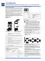
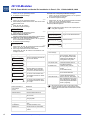
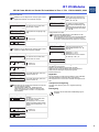
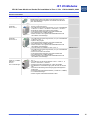
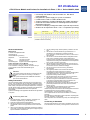
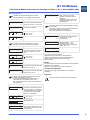
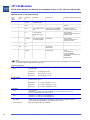
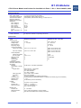
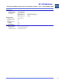
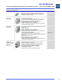
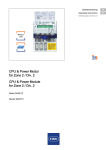
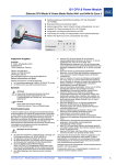
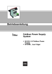
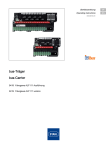
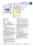
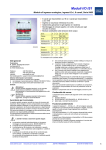
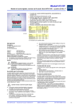
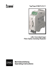
IS1 I/O-Modules
CPU & Power Modul und Sockel für Installation in Zone 1 / Div. 1 Reihe 9440/22, 9490
CPU & Power Modul und Sockel für Installation in Zone 1 / Div. 1 Reihe 9440/22, 9490
> Feldbus und ServiceBus eigensicher gem. RS 485-IS
(PNO-Standard)
> Integrierte Ex i Stromversorgung für bis zu 8 I/O Module
> Profibus DP V0 und V1 HART; Modbus RTU
> Systemredundanz (Profibus Standard)
und Leitungsredundanz möglich
> DTM und ServiceBus-Schnittstelle für Fehlerdiagnose
und Asset Management Systeme
> LCD zur Anzeige vor Ort von Diagnosedaten, Eingangsund Ausgangswerten
> Modul unter Spannung in Zone 1 / Div. 1 austauschbar
(hot swap)
05832E00
Zone
ATEX / IECEx
Class I
(NEC 505) (NEC 506)
Class I Class II Class III
0 1 2 20 21 22
0
1
2
1
2
1
2
x
x
x
x
x
x
x
x
x
x
x
x
x
Installation in
x
x
x*)
x*)
x
x
x*)
x*)
x
x
x*)
x*)
x*)
x*)
Geeignetes Gehäuse notwendig
Hersteller
R. STAHL Schaltgeräte GmbH
Am Bahnhof 30
74638 Waldenburg, Germany
Telefon:
+49 7942 943-0
Telefax:
+49 7942 943-4333
Internet:
www.stahl-ex.com
Service&Support: [email protected]
Weitere Informationen zum Modul
Weitere Informationen zum Modul finden Sie
im Automatisierungskatalog (168465 / 00 006 54 78 0) oder
im Internet unter www.stahl-automatisierung.de
Symbole
Achtung!
Diese Grafik kennzeichnet Hinweise, bei deren Nichtbeachtung Ihre Gesundheit oder die Funktionsfähigkeit
des Gerätes bzw. der Komponente gefährdet ist.
Hinweis
Diese Grafik kennzeichnet wichtige Zusatzinformationen, Tipps und Empfehlungen.
Sicherheitshinweise
In diesem Kapitel sind die wichtigsten Sicherheitsmaßnahmen
zusammengefasst. Es ergänzt die entsprechenden Vorschriften,
zu deren Studium das verantwortliche Personal verpflichtet ist.
Bei Arbeiten in explosionsgefährdeten Bereichen hängt die
Sicherheit von Personen und Anlagen von der Einhaltung aller
relevanten Sicherheitsvorschriften ab. Das Montage- und
Wartungspersonal trägt deshalb eine besondere Verantwortung.
Voraussetzung ist die genaue Kenntnis der geltenden
Vorschriften und Bestimmungen.
Beachten Sie als Anwender:
✗
die nationalen Sicherheits-, Unfallverhütungs-, Montage- und
Errichtungsvorschriften (z.B. IEC/EN 60079-14)
die allgemein anerkannten Regeln der Technik
die Sicherheitshinweise und Angaben dieses Dokuments,
die Kennwerte der Typschilder und die Hinweisschilder
die EG-Baumusterprüfbescheinigung (nach ATEX) bzw.
Konformitäts- oder Teilbescheinigung (nach bisheriger Zulassung) und die darin enthaltenen besonderen Bedingungen
www.stahl-ex.com
20 21 22
x
Allgemeine Angaben
✗
✗
2
Ex
Schnittstelle
*)
✗
1
Betriebsanleitung für das IS1-System
✗
dass Beschädigungen den Explosionsschutz aufheben
können
✗ dass das CPU & Power Modul Typ 9440/22-01-.1 nur für den
Einsatz in explosionsgefährdeten Bereichen der Zone 1/
Division 1, Zone 2/Division 2, Zone 21, Zone 22 oder im
sicheren Bereich zugelassen ist.
✗ dass das CPU & Power Modul mit dem vorgesehenen
Sockel, bei Einsatz in explosionsgefährdeten Bereichen, in
ein Gehäuse eingebaut sein muss, das die Anforderungen
einer anerkannten Schutzart gemäß IEC/EN 60079-0 erfüllt
(z. B. R. STAHL Typ 8126).
✗ dass das Modul als zugehöhriges Betriebsmittel auch in
explosionsgefährdeten Bereichen der Zonen 21 und 22
installiert werden darf, wenn es in ein entsprechend bescheinigtes Gehäuse eingebaut ist.
✗ dass Arbeiten an der Ex e Klemme nur im spannungsfreien
Zustand zulässig sind.
✗ dass nach Anschluss der Hilfsenergie an der Ex e Klemme
die Schutzart IP30 sichergestellt sein muss.
Nicht belegte Anschlussklemmen müssen vor zufälliger
Berührung geschützt sein (z. B. durch gesonderte Abdeckung oder geeigneten Verschluss der Leitungseinführungen).
✗ dass an die Anschlussklemmen vom Sockel nur Adern mit
einem maximalem Leitungsquerschnitt von 2,5 mm2 angeschlossen werden dürfen.
✗ dass bei Verwendung des Sockels 9490/13-12 das freie Leitungsende des fest angeschlossenen Kabels in einem geeigneten, bescheinigten Anschlussraumgehäuse
angeschlossen werden muss.
✗ dass alle an die RS 485 Schnittstellen angeschlossenen Geräte galvanisch voneinander und von allen sonstigen Stromkreisen getrennt sein müssen.
✗ dass die Hutschiene der BusRail mit dem Potentialausgleich
des explosionsgefähdeten Bereichs verbunden sein muss.
Verwenden Sie die Komponenten bestimmungsgemäß nur für
den zugelassenen Einsatzzweck (siehe Kapitel „Funktion/Eigenschaften“). Fehlerhafter und unzulässiger Einsatz sowie das
Nichtbeachten der Hinweise dieses Dokuments schließen eine
Gewährleistung unsererseits aus.
Veränderungen an den Komponenten, die den Explosionsschutz
betreffen, sind nicht gestattet.
Komponenten dürfen nur in unbeschädigtem, trockenem und
sauberen Zustand eingebaut werden.
Normenkonformität
Bitte entnehmen Sie die Normenkonformität der
EG-Konformitätserklärung im Anhang dieses Dokumentes.
162277 / 9440607310
2012-03-06·BA00·III·de·04
1
IS1 I/O-Modules
CPU & Power Modul und Sockel für Installation in Zone 1 / Div. 1 Reihe 9440/22, 9490
Funktion/Eigenschaften
Sub-D-Buchsen X1, X2, X3
Das CPU & Power Modul enthält ein Netzteil zur eigensicheren
Stromversorgung der I/O Module und der Feldstromkreise. Das
Netzteil ist mit einer Unterspannungs-Überwachung ausgestattet.
Die CPU hat die Funktion eines Gateways zwischen dem internen Bus einer IS1 Feldstation und dem Ex i Feldbus, der die
Feldstation über einen Feldbustrennübertrager mit dem Automatisierungssystem verbindet.
Die Versorgung und Kommunikation der I/O Module erfolgt über
die BusRail. Die Schnittstelle des CPU & Power Moduls zum
internen Datenbus der BusRail ist redundant ausgeführt.
Die Elektronik ist druckfest gekapselt und über Steckverbinder Ex
d und Ex i mit dem Sockel verbunden. Der Hilfsenergieanschluss
erfolgt in Ex e oder Conduit.
Komponenten
Übersicht
5 3
8 6
Anschlussbelegung
Pin Nr.
Funktion
RxD/TxD (+)
Daten B (+)
5
GND
Bezugspotential für Geräteschnittstelle
6
PWR (+)
Versorgungsspannung
(Gerät)
8
RxD/TxD (-)
Daten A (-)
1, 2, 4, 7, 9
--
nicht angeschlossen
14
Projektierung
15
✗
Die nationalen Errichtungsbestimmungen
(z. B. IEC/EN 60079-14) müssen beachtet werden.
Eigensichere und nicht-eigensichere Stromkreise dürfen nicht in einem gemeinsamen Kabelkanal geführt
werden!
Zwischen Anschlussteilen eigensicherer und nicht-eigensicherer Stromkreise muss ein Abstand von mindestens 50 mm (Fadenmaß) eingehalten werden!
4
6
7
8
9
10
11
12
13
✗
12223E00
Sockel mit Ex e Klemme
(ohne Modul)
1
2
3
4
5
6
7
8
9
10
11
12
13
14
15
Sockel mit Kabelschwanz
(mit gestecktem Modul)
Abdeckklappe (geöffnet) zur Sicherstellung der
Schutzart IP30
Ex e Klemme (nur bei Sockel 9490/11-12)
Rasthebel zum Entfernen des Moduls vom Sockel
Buchse für Modul
Klemmschraube für DIN-Schiene
Buchse für Modul
Rasthebel zum Entfernen des Moduls vom Sockel
LCD-Anzeige
LED zur Status- bzw. Fehleranzeige (weitere Informationen siehe „LED Anzeigen und Fehlerbehebung“)
Tasten <▲>, <▼>
Sub-D-Buchse X1 (Prozessbus, primär)
Sub-D-Buchse X2 (Prozessbus, redundant)
Sub-D-Buchse X3 (ServiceBus)
Kabelschwanz (nur bei Sockel 9490/13-12)
CPU & Power Modul
Hilfsenergieanschluss
Für den Hilfsenergieanschluss stehen zwei verschiedene Sockel
zur Verfügung:
✗ 9490/11-12: Anschluss über Ex e Klemmen
✗ 9490/13-12: Anschluss über Kabelschwanz
Anschlussbelegung
Ex e Klemme
Klemme Nr.
1
2
4
6
3, 5, 7, 8, 9, 10, 11, 12,
13, 14, 15, 16
2
www.stahl-ex.com
Kabelschwanz
Leiter Nr.
1
2
2
3
--
Beschreibung
3
1
2
3
5
12224E00
✗
✗
✗
BusRail
Betriebsanleitung für das IS1-System
BusRail
05683E00
✗
✗
✗
Funktion
+ 24 V DC
0V
N (90...253 V AC)
L (90...253 V AC)
kein Leiteranschluss
Das Modul ist für IS1 Feldstationen bestimmt und darf in explosionsgefährdeten Bereichen der Zone 1/Division 1,
Zone 2/Division 2, Zone 21 oder Zone 22 installiert werden.
Bei Installation in explosionsgefährdeten Bereichen muss
das CPU & Power Modul mit dem vorgesehenen Sockel in
ein Gehäuse eingebaut werden, das die Anforderungen einer
anerkannten Schutzart gemäß IEC/EN 60079-0 erfüllt
(z. B. R. STAHL Typ 8126).
Sicherstellen, dass das CPU & Power Modul zum Spannungsbereich der Hilfsenergie passt.
Das Modul wird zur bestimmungsgemäßen Verwendung auf
der IS1 BusRail installiert.
Der Betrieb des Moduls ist nur in den drei Montagelagen
zulässig:
Montagerichtung oben:
✗
✗
✗
Das primäre CPU & Power Modul muss auf dem ersten
Steckplatz der BusRail montiert sein.
Das redundante CPU & Power Modul (optional) muss auf
dem zweiten Steckplatz der BusRail montiert sein.
Bei Einsatz in explosionsgefährderten Bereichen müssen
zwischen die Feldbus-Anschlüssen (X1, X2, X3) und dem
Automatisierungssystem geeignete Feldbus-Trennübertrager eingesetzt werden (z. B. R. STAHL
Reihe 9185 oder 9186).
Dies gilt auch dann, wenn das CPU & Power Modul im sicheren Bereich installiert ist aber Feldbus-Stromkreise der angeschlossenen I/O-Module in den explosionsgefährdeten
Bereich führen.
Die Hutschiene der BusRail muss mit dem Potentialausgleich des explosionsgefähdeten Bereichs verbunden sein.
An den angeschlossenen Hilfsenergie-Stromkreisen (Ex e)
darf nur im spannungsfreien Zustand gearbeitet werden.
Nach Anschluss der Hilfsenergie muss an der Ex e Klemme
die Schutzart IP30 sichergestellt sein (z. B. durch gesonderte
Abdeckung).
162277 / 9440607310
2012-03-06·BA00·III·de·04
IS1 I/O-Modules
CPU & Power Modul und Sockel für Installation in Zone 1 / Div. 1 Reihe 9440/22, 9490
Montage und Installation
Die nationalen Errichtungsbestimmungen (z. B. IEC/
EN 60079-14) müssen beachtet werden.
Eigensichere und nicht-eigensichere Stromkreise dürfen nicht in einem gemeinsamen Kabelkanal geführt
werden!
Zwischen Anschlussteilen eigensicherer und nicht-eigensicherer Stromkreise muss ein Abstand von mindestens 50 mm (Fadenmaß) eingehalten werden!
Arbeiten an den Ex e Klemmen oder am Kabelschwanz
sind nur im spannungsfreien Zustand zulässig!
Wenn die Feldstation mit zwei CPU und Power Modulen (primär und redundant) bestückt ist, müssen beide
CPU & Power Module spannungsfrei oder aus dem Sockel gezogen sein!
An dem Sockel darf entweder nur die Hilfsenergie
20...35 V DC für das CPM 9440/22-01-11 oder
90...230 V AC für das CPM 9440/22-01-21 angeschlossen werden.
Der gleichzeitige Anschluss beider Hilfsenergien ist
nicht zulässig!
Beim Sockel mit Kabelschwanz müssen die nicht benutzten Leiter isoliert werden (z. B. durch Auflegen auf
eine Ex e Klemme)!
Austausch des Sockels
Arbeiten an den Ex e Klemmen oder am Kabelschwanz
sind nur im spannungsfreien Zustand zulässig!
•
•
•
•
•
•
•
•
•
•
•
•
•
•
•
•
Hilfsenergie spannungsfrei schalten.
Rasthebel (3 und 7) in Position “II“ schieben.
Modul senkrecht bis zum Anschlag aus dem Sockel ziehen.
Rasthebel in Position “I“ schieben.
Modul senkrecht aus dem Sockel entfernen.
Hilfsenergie von Ex e Klemme entfernen bzw. Kabelschwanz
von Hilfsenergie trennen.
Feldbus-Anschlüsse von den Sub-D-Buchsen entfernen.
Klemmschrauben des Sockels lösen.
Sockel senkrecht von BusRail abziehen.
Neuen Sockel senkrecht auf BusRail setzen.
Sockel durch leichtes Drücken einrasten.
Klemmschrauben des Sockels anziehen, um Sockel auf BusRail zu fixieren.
Modul senkrecht auf Sockel stecken.
Modul durch leichtes Drücken einrasten.
Feldbusse wieder an Sub-D-Buchsen anschließen.
Hilfsenergie wieder anschließen.
Parametrierung und Inbetriebnahme
Die Parametrierung und Inbetriebnahme des CPM und
der angeschlossenen I/O-Module erfolgt über das Automatisierungssystem und den ServiceBus (optional).
Nur die Feldbusadresse des CPM muss direkt am Sokkel eingestellt werden.
Über die LCD-Anzeige mit Tasten im Sockel lassen
sich:
die Feldbusadresse des CPU & Power Moduls einstellen und
Informationen über das CPU & Power Modul und die
auf der BusRail installierten I/O-Modulen anzeigen.
Das CPU & Modul kann während des Betriebs im explosionsfähigen Bereich gefahrlos gesteckt oder gezogen werden (hot swap).
An dem CPU & Modul können bis zu acht I/O-Module
betrieben werden.
Die Sub-D-Stecker können während des Betriebs im
explosionsfähigen Bereich gefahrlos gesteckt oder gezogen werden (hot swap).
StartUp
Nach Anlegen der Hilfsenergie bootet das CPU & Power Modul.
Nach erfolgreichem Bootvorgang wechselt die LCD-Anzeige in
die Systemebene.
Montage auf BusRail
Der Betrieb des Moduls ist nur in folgenden Montagelagen zulässig:
Montage des Sockels: Senkrecht mit LCD-Anzeige unten, links oder rechts.
Sockel senkrecht auf ersten Steckplatz der BusRail aufsetzen.
• Sockel durch leichtes Drücken einrasten.
• Klemmschrauben (5) des Sockels anziehen, um den Sockel
auf der BusRail zu fixieren.
• Gegebenenfalls Sockel für redundantes Modul auf zweiten
Steckplatz der BusRail montieren.
• Rasthebel (3 und 7) in Position “I“ schieben.
• Modul senkrecht auf Sockel aufsetzen.
• Modul durch leichtes Drücken einrasten.
• Gegebenenfalls redundantes Modul auf zweiten Sockel
montieren.
• Sockel an Hilfsenergie anschließen (Anschlussbelegung der
Ex e Klemme bzw. des Kabelschwanzes siehe “Komponenten“).
• Nach Anschluss der Hilfsenergie sicherstellen, dass an der
Ex e Klemme die Schutzart IP30 eingehalten wird bzw. das
nicht benutzte Leiter des Kabelschwanzes isoliert sind!
• Feldbus an Sub-D-Buchse X1 des Sockels anschließen.
• Gegebenenfalls redundanten Feldbus an Sub-D-Buchse X2
und/oder ServiceBus an Sub-D-Buchse X3 des Sockels anschließen.
Austausch des Moduls
• Rasthebel (3 und 7) in Position “II“ schieben.
• Modul senkrecht bis zum Anschlag aus dem Sockel ziehen.
• Rasthebel in Position “I“ schieben.
• Modul senkrecht aus dem Sockel entfernen.
• Neues Modul senkrecht auf Sockel aufsetzen.
• Modul durch leichtes Drücken einrasten.
FBAdr
5
Betriebsanleitung für das IS1-System
I/O
OK
12258E00
Einstellen der Feldbusadresse
Nach dem Einstellen der Feldbusadresse bootet das
CPU & Power Modul erneut.
Die Feldbusadresse ist permanent gespeichert und
steht auch nach einem Reset oder einer Wiederinbetriebnahme zur Verfügung.
•
www.stahl-ex.com
FB
OK
Die Feldbusadresse kann nur eingestellt werden, wenn
sich das CPU & Power Modul nicht im Zustand Data
Exchange befindet.
• Tasten „▲“ und „▼“ gleichzeitig drücken.
✔ Es erscheint folgende Anzeige:
CPM
active
9440/15-01-11
• Tasten „▲“ und „▼“ gleichzeitig drücken.
✔ Es erscheint folgende Anzeige:
12259E00
CPM
active
FB addr :
5
• Tasten „▲“ und „▼“ gleichzeitig drücken.
✔ Es erscheint folgende Anzeige:
12260E00
set FB address
select:
5
•
12261E00
Taste „▲“ oder „▼“ so lange drücken, bis gewünschte Feldbusadresse eingestellt ist.
Bei dauerndem Drücken der Taste wird der Wert
schnell geändert.
Der Einstellbereich geht von 0 bis 127.
162277 / 9440607310
2012-03-06·BA00·III·de·04
3
IS1 I/O-Modules
CPU & Power Modul und Sockel für Installation in Zone 1 / Div. 1 Reihe 9440/22, 9490
Informationen zu Output/Input Modulen anzeigen
• Tasten „▲“ und „▼“ gleichzeitig drücken, um von Systemebene in Modulebene zu wechseln.
✔ Es erscheint folgende Anzeige:
• Tasten „▲“ und „▼“ gleichzeitig drücken.
✔ Es erscheint folgende Anzeige:
accept changes ?
yes -> CPM reset
12262E00
• Tasten „▲“ und „▼“ gleichzeitig drücken.
✔ Die Einstellungen werden übernommen. Das CPU & Power
Modul bootet erneut.
oder:
• Taste „▲“ oder „▼“ drücken.
✔ Es erscheint folgende Anzeige:
accept changes ?
No
12263E00
• Tasten „▲“ und „▼“ gleichzeitig drücken.
✔ Die Einstellung wird abgebrochen.
Feldstation in Betrieb nehmen
• Zyklischen Datenverkehr mit dem Master in Betrieb setzten.
Informationen zu CPU & Power Modul anzeigen
• Tasten „▲“ und „▼“ gleichzeitig drücken, um von Systemebene in Modulebene zu wechseln.
✔ Es erscheint folgende Anzeige:
CPM
active
9440/15-01-11
•
•
✔
•
12259E00
Mit der Taste „▲“ oder „▼“ gewünschtes Modul auswählen.
Tasten „▲“ und „▼“ gleichzeitig drücken.
Die Anzeige wechselt in die Informationsebene.
Mit der Taste „▲“ oder „▼“ zwischen verschiedenen LCDAnzeigen wechseln.
LCD-Anzeige
Anzeige/Funktion
CPM
active
FB addr :
5
Kopplungsart
12264E00
CPM
status
config/para fail
12265E00
CPM
back
active
12266E00
CPM
active
exit menu
12267E00
Die folgenden Anzeigen sind für alle Output/Input Module gleich aufgebaut.
LCD-Anzeige
Anzeige/Funktion
Status des CPU & Power Moduls
(Mögliche Status-Informationen
siehe Tabelle „Status-Informationen des CPU & Power Moduls“)*
Wechsel zurück in die Modulebene
des CPU & Power Moduls durch
gleichzeitiges Drücken der Tasten
„▲“ und „▼“.
Anzeige des Steckplatzes, des Modultyps und des Modulzustands**.
slot 2:
AOM
module OK/mode:0
12268E00
Anzeige der Firmware- und der
Hardvere-Revision.
slot 1:
AOM
FW 02-04, HW ‘E’
12269E00
Anzeige der Seriennummer.
slot 3:
AOM
SNo: 123456-7890
12270E00
** mögliche Modulzustände:
Status-Information
in LCD-Anzeige
IOM no response
Zustand und Feldbus-Adresse des
CPU & Power Moduls
12260E00
CPM information
Modbus
V10-00
• Mit der Taste „▲“ oder „▼“ gewünschtes Modul auswählen.
• Tasten „▲“ und „▼“ gleichzeitig drücken.
✔ Die Anzeige wechselt in die Informations-/Serviceebene.
Output/Input Module allgemein:
hardware failure
conf unequal mod
HW disable outp.
prim. Rail fail
red. Rail fail
module OK/mode: x
Wechsel zurück zur Hauptanzeige
des CPU & Power Moduls durch
gleichzeitiges Drücken der Tasten
„▲“ und „▼“.
Bedeutung
Prio
Kommunikation mit dem Modul
ist nicht möglich. Modul ist defekt, nicht gesteckt oder beide
BusRail bzw das BusRail-Verbindungskabel sind gestört.
Modul meldet Hardwarefehler.
Konfigurationsfehler oder falsches Modul gesteckt.
Ausgänge durch externen
Schalter (Anlagen Aus) abgeschaltet
(nur bei DOM 9475/2)
keine Kommunikation über primären BusRail-Datenbus
keine Kommunikation über redundanten BusRail-Datenbus
Modul in Ordnung. Kein Modulfehler. Signalfehler können trotzdem vorhanden sein. Zusätzlich
wird die konfigurierte Betriebsart
(mode:x) angezeigt.
1
2
3
4
5
5
6
* Status-Informationen des CPU & Power Moduls:
Status-Information in
LCD-Anzeige
no error
hardware fail (1)
hardware fail (2)
hardware fail (3)
DataExch AS (2)
no DataExch
config/para fail
quit DataExch
DataExch As
4
www.stahl-ex.com
Bedeutung
kein Fehler
Hardwarefehler gefunden
falsche Hardware Kennung
keine Kommunikation zwischen
CPR und IOP
Data Exchange mit dem Automatisierungssystem
kein Datenaustausch
Konfigurations- oder Parameterfehler
kein Datenaustausch mehr
Data Exchange mit Automatisierungssystem, Konfiguration durch
Profibus
Betriebsanleitung für das IS1-System
Bei mehreren Fehlern wird nur der Fehler mit der
höchsten Priorität angezeigt. Nach Beheben dieses
Fehlers wird der Fehler mit der nächsthöheren Priorität
angezeigt.
162277 / 9440607310
2012-03-06·BA00·III·de·04
IS1 I/O-Modules
CPU & Power Modul und Sockel für Installation in Zone 1 / Div. 1 Reihe 9440/22, 9490
Digital Output Module:
Zusätzlich zu den allgemeinen Anzeigen gibt es beim
Digital Output Modul noch folgende Anzeigen:
LCD-Anzeige
Anzeige/Funktion
slot 1:
DOM
1 1 0 0 1 0 1 1
12271E00
slot 1:
DOM
safety position
12272E00
slot
. .
1:
. .
IO Daten.
Der Wert für Kanal 0 steht links,
der für Kanal 7 rechts.
Ohne Ausgabedaten wird Sicherheitszustand der Ausgänge angezeigt.
IO Fehler
DOM
. .
12273E00
: Drahtbruch
: Kurzschluss
slot 3:
single I/O
AOM
12284E00
slot 3:
AOM
I/O 0: safety pos
12285E00
Analog Module mit HART:
Für die HART Module 9461 und 9466 können die
HART PV dargestellt werden.
Das Untermenü erscheint nur, wenn die Analog Module
für die Übertragung von HART PV konfiguriert sind.
Es werden nur die konfigurierten HART PV angezeigt.
LCD-Anzeige
Anzeige/Funktion
12274E00
Digital Input Module:
slot 4:
HART PV
AIM
Zusätzlich zu den allgemeinen Anzeigen gibt es beim
Digital Input Modul noch folgende Anzeigen:
LCD-Anzeige
Anzeige/Funktion
slot 2:
DIM
1100011011011010
12276E00
1:
. .
IO Daten.
Der Wert für Kanal 0 steht links,
der für Kanal 15 rechts.
IO Fehler
DOM
. .
12273E00
: Drahtbruch
: Kurzschluss
IO Daten und Fehler
1100011011011010
. .
. .
. .
12278E00
s 3/14:
0
Counter: reset
12279E00
s 3/15:
100
Counter: start
12280E00
Anzeige des Zähler-/Frequenzwertes und der Steuerbits „start“ und
„reset“ für Kanal 14.
Anzeige des Zähler-/Frequenzwertes und der Steuerbits „start“ und
„reset“ für Kanal 15.
Analog Output Modul/Analog Input Module:
Das Menü für die Analog Output Module und die Analog Input Module ist gleich.
Für die Module AOMH 9461, AOMH 9466 und
TIM R 9480 gibt es noch zusätzliche Menüpunkte
(siehe „Analog Module mit HART“ und „Temperatur
Input Module“).
LCD-Anzeige
slot
3:
3:
. .
AOM
s s
. .
slot 4:
AIM
PV 1:
-16.234
12287E00
slot 4:
PV 3:
AIM
#.###
Anzeige der konfigurierten PV.
Betriebsart 1 = 4 PV,
Betriebsart 2 = 8 PV.
Wechseln der PV durch Drücken
der Taste „▲“ oder „▼“.
Anzeige von „not a number“
12288E00
Wartung und Instandhaltung
Das Modul ist wartungsfrei.
Beachten Sie die bestimmungsgemäße Funktion.
Halten Sie sich an die Richtlinien nach IEC/EN 60079-17.
Halten Sie die zulässigen Temperaturen gemäß
IEC/EN 60079-0 ein.
Reparatur
Für die Reparatur schicken Sie das Modul an Ihre zuständige
Vertriebsorganisation (Adresse siehe www.stahl.de).
Die Reparatur darf nur durch den Hersteller durchgeführt werden!
Transport und Lagerung
Transport und Lagerung sind nur in Originalverpackung
gestattet.
Entsorgung
Beachten Sie die nationalen Abfallbeseitigungsvorschriften!
IO Daten.
Der Wert für Kanal 0 steht links,
der für Kanal 7 rechts.
Bei Ausgängen, die noch keine
gültigen IO Daten erhalten haben,
wird die Sicherheitsstellung ’s’ angezeigt.
IO Fehler
AOM
. .
12282E00
. .
12286E00
Menü zur Anzeige der HART PV.
Aufruf der Untermenüs durch
gleichzeitiges Drücken von „▲“
und „▼“.
Anzeige/Funktion
12281E00
slot
. .
Anzeige von IO Fehler oder IO Daten. Ist kein IO Wert vorhanden,
wird die Sicherheitsstellung angezeigt.
Wechseln zwischen Kanälen durch
gleichzeitiges Drücken der Tasten
„▲“ oder „▼“.
IO Daten und Fehler
1 1 0 0 1 0 1 1
. .
. .
. .
slot
. .
Anzeige der IO Daten für einzelne
Kanäle. Aufruf des Untermenüs
durch gleichzeitiges Drücken der
Tasten „▲“ oder „▼“.
: Drahtbruch
: Kurzschluss
IO Daten und Fehler
s s
. .
12283E00
www.stahl-ex.com
Betriebsanleitung für das IS1-System
162277 / 9440607310
2012-03-06·BA00·III·de·04
5
IS1 I/O-Modules
CPU & Power Modul und Sockel für Installation in Zone 1 / Div. 1 Reihe 9440/22, 9490
LED Anzeigen und Fehlerbehebung
LED grün
“RUN“
LED rot
“ERR“
LCD-Anzeige
CPM Zustand
Fehlerquelle
Mögliche Behebung
Ein
Aus
FB: OK
I/O: OK
Alle Module OK
Alle Signale OK
keine
--
FB: OK
I/O: err
CPM: OK
Sammelalarm I/O-Signal
siehe LED-Anzeigen der
I/O-Module
CPM: OK
I/O: Modul-Sammelalarm
• Module gestört
• Modul nicht vorhanden
• Falsches Modul gesteckt
• Modul tauschen
• Modul stecken
• Richtiges Modul stecken
Ein
Blinkt
FB: OK
I/O: err
Blinkt
Aus
FB: off/baud In Bereitschaft (nach keine
I/O: -dem Einschalten, aber
noch ohne Datenaustausch mit dem Master)
Blinkt
Blinkt
FB: off/baud Data Exchange wurde Zyklischer Datenverkehr mit dem Zyklischen Datenverkehr mit
I/O: OK/err
dem Master in Betrieb setzen.
verlassen (Ausgänge Master ist unterbrochen.
Master und Busverbindung zu
in Sicherheitsstellung)
CPM prüfen.
Blinkt
Ein
FB: off/baud Konfigurationsfehler
I/O: --
Konfiguration ist nicht in Ordnung
Konfiguration des Masters ändern
Aus
Ein oder
Blinkt
FB: off/baud CPM Hardwarefehler
I/O: --
• Hardware-Check-Fehler
• Eprom-Fehler
• EEprom-Fehler
CPM tauschen.
Aus
Aus
keine
Anzeige
Keine Versorgungsspannung am • Versorgung des CPM prüfen.
CPM vorhanden oder CPM de• CPM prüfen.
fekt.
• BusRail prüfen.
• CPM richtig auf BusRail aufrasten.
• CPM tauschen.
Aus
Zyklischen Datenverkehr mit
dem Master in Betrieb setzen.
Master und Busverbindung zu
CPM prüfen.
Hinweis
Wenden Sie sich an Ihre zuständige Vertriebsniederlassung oder unsere Service-Abteilung
([email protected]), wenn sich der Fehler mit den vorgeschlagenen Behebungsmöglichkeiten nicht
beheben lässt.
Explosionsschutz
Global (IECEx)
Gas
KEM 08.0038X
Europa (ATEX)
Gas
9440/22-01-.1:
Ex d [ia] [ib] IIC T4 Gb
9490/11-12:
Ex d e [ia] [ ib] IIC T4 Gb
9490/13-12:
Ex d mb [ia] [ib] IIC T4 Gb
KEMA 02 ATEX 1333 X
USA (NEC)
Gas
9440/22-01-.1:
E II 2 G Ex d [ia] [ib] IIC T4 Gb
9490/11-12:
E II 2 G Ex d e [ia] [ ib] IIC T4 Gb
9490/13-12:
E II 2 G Ex d mb [ia] [ib] IIC T4 Gb
3007532 (FM)
9440/22-01-.1 & 9490/12-12: XP/I/1/ABCD/T6 Ta = 65 °C,
XP/I/1/IIC/T4 Ta = 65 °C,
AIS/I,II,III/1/ABCDEFG,
AIS/I/1/[AEx ia, ib] IIC
Russland (GOST-R)
Gas
9440/22-01-.1 & 9490/11-12: 2Exde[ia/ib]IICT4
9440/22-01-.1 & 9490/13-12: 2Exdm[ia/ib]IICT4
Bescheinigungen und Zulassungen
Bescheinigungen
IECEx, ATEX, Brasilien (INMETRO), Indien (PESO), Kanada (CSA), Kasachstan (GOST-K),
Russland (GOST-R), Serbien (SRPS), Weißrussland (GOST-B), USA (FM)
Weitere Zulassungen
Schiffszulassung (DNV, ABS, GL, ClassNK)
6
www.stahl-ex.com
Betriebsanleitung für das IS1-System
162277 / 9440607310
2012-03-06·BA00·III·de·04
IS1 I/O-Modules
CPU & Power Modul und Sockel für Installation in Zone 1 / Div. 1 Reihe 9440/22, 9490
Explosionsschutz
Sicherheitstechnische Daten
Maximale
Ausgangsspannung
Anschluss an
eigensicheren RS 485-IS
Feldbus
Höchstwerte für Feldbus
und ServiceBus
(RS485-IS)
Maximale Spannung
Uo
Maximale Spannung Ui
Maximaler Strom Io
Maximale Leistung Po
Maximale Kapazität Co
für IIC
Maximale Induktivität
Lo für IIC
Weitere Parameter
Weitere Angaben
Technische Daten
Elektrische Daten
Typen
Hilfsenergie
Nennspannung
Spannungsbereich
Netzfrequenz
Frequenzbereich
Stromaufnahme
ohne I/O Module
mit 8 I/O Modulen
Verlustleistung
ohne I/O Module
je I/O-Modul
Verpolschutz
Unterspannungsüberwachung
Schnittstellen Feldbus,
Feldbus redundant und
ServiceBus
Schnittstelle
Leitungslänge /
Übertragungsrate
Kupferkabel
Lichtwellenleiter
ServiceBus
Hinweis
Leitungsabschluss
Adressbereich
Redundanz
Profibus
Versionen
Übertragungsgeschwin
digkeit
Datenübertragung
Modbus RTU
Übertragungsgeschwindigkeit
Datenübertragung
Funktionen
www.stahl-ex.com
Uout = 26,2 V für Stromversorgung der I/O Module
Global (IECEx): PTB 11.0027, Ex ib IIC T4
Europa (ATEX): PTB 04 ATEX 2089, E II 2 G Ex ib IIC T4
3,7 V
+/- 4,2 V
134 mA
124 mW
1000 mF
1,9 mH
siehe jeweilige Bescheinigung und Betriebsanleitung
9440/22-01-11 (24 V DC)
9440/22-01-21 (90 ... 253 V AC)
24 V DC
20 ... 35 V DC
---
120 V / 230 V AC
90 ... 253 V AC
50 / 60 Hz
45 ... 66 Hz
ca. 0,21 A bei 24 V DC
ca. 25 mA bei 230 V AC,
ca. 48 mA bei 120 V AC
ca. 0,4 A bei 230 V AC,
ca. 0,8 A bei 120 V AC
ca. 2,5 A bei 24 V DC
5W
ca. 1,4 W
ja
ja
8,4 W
ca. 1 W
entfällt
ja
RS 485-IS nach Profibus Spezifikation
1200 m bei 9,6 ... 93,75 kbit/s
1000 m bei 187,5 kbit/s
400 m bei 500 kbit/s
200 m bei 1,5 Mbit/s
ca. 2000 m bei 1,5 Mbit/s
1200 m bei 9,6 kbit/s
weitere Angaben siehe Betriebsanleitung
gespeister Widerstand (Abschlusswiderstand im Sub-D Stecker, siehe Zubehör)
0 ... 127
Vollredundanz und Leitungsredundanz
DP V0, DP V1, DP V1 HART
9,6 kbit/s ... 1,5 Mbit/s
ca. 40 16-Bit-Worte / ms (zyklisch, netto bei 1,5 Mbit/s)
9,6 ... 38,4 kbit/s
ca. 1000 16-Bit-Register / s (bei 38,4 kbit/s)
Read, Write; siehe Kopplungsbeschreibung Modbus RTU
Betriebsanleitung für das IS1-System
162277 / 9440607310
2012-03-06·BA00·III·de·04
7
IS1 I/O-Modules
CPU & Power Modul und Sockel für Installation in Zone 1 / Div. 1 Reihe 9440/22, 9490
Technische Daten
Kennwerte
Max. interne
Signalverzögerung bei
8 I/O Modulen (ohne
Modulverzögerung)
für Digital-Module
für Analog-Module
Bediener-Schnittstelle
Software
Betrieb
Fehler
LCD-Anzeige
Einstellungen
Anzeigen
Diagnose und
Parametrierung
Funktionen
Anschließbare
Softwarepakete
Stromversorgung für I/O
Module über die BusRail
Spannungsbereich
Max. Strom
Max. Anzahl
I/O-Module
Redundante
Versorgung der
I/O-Module
Unterspannungsüberwachung
Galvanische Trennung
zwischen Hilfsenergie
und
Systemkomponenten
zwischen Feldbus-/
ServiceBusSchnittstelle und
Systemkomponenten
zwischen zwei BusSchnittstellen
Umgebungsbedingungen
Umgebungstemperatur
Lagertemperatur
Maximale relative
Luftfeuchte
Vibration, sinusförmig
(IEC EN 60068-2-6)
Schock, halbsinusförmig
(IEC EN 60068-2-27)
Elektromagnetische
Verträglichkeit
8
www.stahl-ex.com
7 ms
10 ms
IS1 Geräte DTM oder IS Wizard
LED grün "RUN"
LED rot "ERR"
2 x 16 Zeichen
Busadresse
Busadresse, Alarme / Fehler, Informationen (Typ, Revision usw.) für die Ebenen Feldstation,
Module und Signale, Werte der Eingänge und Ausgänge
•
•
•
•
•
•
•
•
•
•
•
•
•
Konfigurationsdaten und Parameter in IS1 Feldstationen laden oder rücklesen
Eingänge lesen
Ausgänge lesen und schreiben
Diagnosedaten übertragen (z.B. Konfig-Fehler, Hardware-Fehler, Signal-Fehler)
HART Kommandos von / zu HART Feldgeräten übertragen
IS Wizard (über R. STAHL ServiceBus)
R. STAHL DTM (über R. STAHL ServiceBus)
AMS von Emerson Process Management
PDM von Siemens
PRM und Fieldmate von Yokogawa
FieldCare von Endress + Hauser
FDM von Honeywell
etc.
22,5 ... 26,2 V DC
2A
8
ja (mit Dioden entkoppelt)
ja
1500 V AC
500 V AC
500 V AC
- 20 ... + 65 °C
- 40 ... + 70 °C
95 % (keine Betauung)
1 g im Frequenzbereich 10 ... 500 Hz
2 g im Frequenzbereich 45 ... 100 Hz
15 g (3 Schocks pro Achse und Richtung)
Geprüft nach folgenden Normen und Vorschriften: EN 61326-1 (1998)
IEC 1000-4-1...6, NAMUR NE 21
Betriebsanleitung für das IS1-System
162277 / 9440607310
2012-03-06·BA00·III·de·04
IS1 I/O-Modules
CPU & Power Modul und Sockel für Installation in Zone 1 / Div. 1 Reihe 9440/22, 9490
Technische Daten
Elektrischer Anschluss
Feldbus RS 485
ServiceBus RS 485
Hilfsenergie
Mechanische Daten
Modulgehäuse
Brandfestigkeit (UL 94)
Schutzart (IEC 60529)
Module
Anschlüsse
Montage / Installation
Einbaubedingungen
Montageart
Einbaulage
www.stahl-ex.com
Sub-D Buchse 9-polig
Sub-D Buchse 9-polig
Sockel 9492/11-12
Sockel 9492/13-12
Sockel 9492/12-12
Ex e Klemmen 2,5 mm2
Kabelschwanz, 5 m, 1 mm2 je Ader
Conduit
Polyamid 6GF
HB
IP30
IP20
auf 35 mm DIN Schiene NS 35/15
waagrecht und senkrecht
Betriebsanleitung für das IS1-System
162277 / 9440607310
2012-03-06·BA00·III·de·04
9
IS1 I/O-Modules
CPU & Power Modul und Sockel für Installation in Zone 1 / Div. 1 Reihe 9440/22, 9490
170 mm / 6.7 "
Maßzeichnungen (alle Maße in mm / Zoll) - Änderungen vorbehalten
96,5 mm / 3.92 "
287 mm / 11.3 "
09877E00
CPU & Power Modul für Zone 1 mit Anschluss über
Ex e Klemmen
07762E00
CPU & Power Modul für Division 1 mit Anschluss über
Conduit
07760E00
CPU & Power Modul für Zone 1 mit Anschluss über
Kabelschwanz
10
www.stahl-ex.com
Betriebsanleitung für das IS1-System
162277 / 9440607310
2012-03-06·BA00·III·de·04
IS1 I/O-Modules
CPU & Power Modul und Sockel für Installation in Zone 1 / Div. 1 Reihe 9440/22, 9490
Zubehör und Ersatzteile
Bezeichnung
Abbildung
Sub-D-Stecker
Beschreibung
Bestellnummer
9-polig zum Anschluss von Feldbus bzw. ServiceBus an CPU & Power
Module Reihe 9440/22 und Feldbus Trennübertrager 9185. Der
Abschlusswiderstand ist eingebaut und schaltbar. Für RS 485 IS
(nach PNO Standard)
162693
• Trennübertrager für Installation in Zone 1 und Zone 2 / Class I
Division 2 und Class I Zone 1
• Für Feldbusse über optisch eigensichere „ex op is“ Lichtwellenleiter
in die Zone 1 / Class I, II, III Division 1 und Class I, II, III Zone 0
• Redundanter Aufbau über optischen Ring möglich
• Umfangreiche Diagnosefunktion und Fehlermeldekontakt
• Für Profibus DP bis 1,5 MBit/s geeignet
• Weitere Varianten und Angaben siehe Datenblatt Reihe 9186
LWL-Feldbus-Trennübertrager
9186/12-11-11
• Trennübertrager zur Installation in Zone 2 / Div. 2
• Für Feldbusse über optisch eigensichere „ex op is“ Lichtwellenleiter
in die Zone 1 / Div. 1
• Optischer Ring möglich
• Umfangreiche Diagnosefunktion und Fehlermeldekontakt
• Für Profibus DP bis 1,5 MBit/s geeignet
• Weitere Varianten und Angaben siehe Datenblatt Reihe 9186
LWL-Feldbus-Trennübertrager
9186/15-12-11
• Trennübertrager zur Installation in Zone 2 / Div. 2
• Für Feldbusse über optisch eigensichere „ex op is“ Lichtwellenleiter
in die Zone 1 / Div. 1
• Punkt-zu-Punkt oder Linienstruktur
• Umfangreiche Diagnosefunktion und Fehlermeldekontakt
• Für Profibus DP bis 1,5 MBit/s geeignet
• Weitere Varianten und Angaben siehe Datenblatt Reihe 9186
LWL-Feldbus-Trennübertrager
9186/25-12-11
• Betriebsmittel zur Installation im sicheren Bereich oder Zone 2 /
Div. 2
• Für Feldbusse mit RS 485-Schnittstelle - Zone 1 / Class I, II, III
Division 1 und Class I, II, III Zone 1
• Geeignet für Profibus DP, Modbus, R. STAHL ServiceBus
• Schnittstelle zum Automatisierungs-System RS 232, RS 422, RS
485
• Automatische Einstellung der Übertragungsgeschwindigkeit bei
Profibus DP
• Übertragungsgeschwindigkeit einstellbar (1,2 kBit/s bis 1,5 MBit/s)
• 24 V AC/DC Hilfsenergie
• Weitere Angaben siehe Datenblatt Reihe 9185/11
9185/11-35-10s
09868E00
LWL-Feldbus-Trennübertrager,
Zone 1 / Div. 1
11131E00
LWL-Feldbus-Trennübertrager,
Zone 2 / Div. 2
11550E00
Feldbus-Trennübertrager, bis 1,5 MBit/s;
Nicht-Ex- /
Zone 2- /
Div. 2-Anwendungen
09867E00
www.stahl-ex.com
Betriebsanleitung für das IS1-System
162277 / 9440607310
2012-03-06·BA00·III·de·04
11
IS1 I/O-Modules
CPU & Power Modul und Sockel für Installation in Zone 1 / Div. 1 Reihe 9440/22, 9490
EG-Konformitätserklärung
Hinweis
Die aktuelle Baumusterprüfbescheinigung mit allen Ergänzungen finden Sie unter www.stahl.de.
12
www.stahl-ex.com
Betriebsanleitung für das IS1-System
162277 / 9440607310
2012-03-06·BA00·III·de·04
IS1 I/O-Modules
CPU & Power Module and Sockets for Installation in Zone 1 / Div. 1 Series 9440/22, 9490
CPU & Power Module and Sockets for Installation in Zone 1 / Div. 1 Series 9440/22, 9490
> Intrinsically safe fieldbus and ServiceBus acc. RS 485-IS
(PNO-Standard)
> Integrated Ex i power supply for up to 8 I/O modules
> Profibus DP V0 and V1 HART; Modbus RTU
> System redundancy (Profibus standard) and media redundancy
> DTM and ServiceBus interface for fault diagnostics and Asset
Management System
> LCD for local display of diagnostic data, input and output values
> Module can be replaced in Zone 1 / Div. 1 in operation (hot swap)
ATEX / IECEx
Zone
05832E00
1
2
1
2
1
2
1
2
x
x
x
x
x
x
x
x
x
x
x
x
x
Installation in
x
x
x*)
x*)
x
x
x*)
x*)
x
x
x*)
x*)
x*)
x*)
Telephone:
+49 7942 943-0
Fax:
+49 7942 943-4333
Internet:
www.stahl-ex.com
Service&Support: [email protected]
Further Information on the Module
Further information on the module you will find
in the automation catalogue (168465 / 00 006 54 78 0) or
on the internet at www.stahl-automatisierung.de
Symbols
Attention!
This symbol marks notes whose non-observance will
endanger your health or functioning of the device.
Note
This symbol marks important additional information,
tips and recommendations.
Safety Instructions
The most important safety instructions are summarised in this
section. They supplement the corresponding regulations which
the personnel in charge must study. When working in hazardous
areas, safety of the personnel and plant depends on complying
with all relevant safety regulations. Assembly and maintenance
staff working on installations therefore have particular
responsibility.
A precise knowledge of the applicable standards and regulations
is required.
As the user, please note:
✗
the national safety, accident prevention, assembly and
installation regulations (e.g. IEC/EN 60079-14)
generally recognised technical regulations,
the safety instructions and information of this document,
characteristic values of the type labels and the instruction
plates.
the EC Type Examination Certificate (according to ATEX) or
conformity or partial certificate (after previous approval) and
special conditions contained in it.
www.stahl-ex.com
20 21 22
suitable enclosure necessary
Manufacturer
R. STAHL Schaltgeräte GmbH
Am Bahnhof 30
74638 Waldenburg, Germany
✗
✗
0
x
General Information
✗
Class I Class II Class III
Ex interface
*)
0 1 2 20 21 22
Class I
(NEC 505) (NEC 506)
Operating Instructions for the IS1-System
✗
that any damage may render explosion protection null and
void.
✗ that the CPU & Power Module of type 9440/22-01-1 is
certified only for application in hazardous areas of
Zone 1/Division 1, Zone 2/Division 2, Zone 21, Zone 22 or in
the safe area.
✗ that the CPU & Power Module with the designated socket
when used in hazardous areas must be fitted into an
enclosure which complies with recognised ingress protection
requirements according to IEC/EN 60079-0 for the respective
zone (e.g. B. R. STAHL Type 8126).
✗ that the module as associated equipment may also be installed in hazardous areas of Zone 21 and 22 if it is fitted into
an enclosure which is certified accordingly.
✗ that work on the Ex e terminal is only permitted if
de-energised.
✗ that ingress protection IP30 must be ensured after
connecting the power supply to Ex e terminal.
Unassigned connection terminals must be protected against
unintended contact (e.g. using a special cover or an
appropriate sealing of cable entries).
✗ that the terminals of the socket may only be connected to
wires with a maximum cross section of 2.5 mm2.
✗ that when using the socket 9490/13-12 the loose cable end
of the firmly connected cable must be connected in an
appropriate certified terminal compartment.
✗ that all devices connected to the RS 485 interface must be
galvanically isolated from each other and from all other
electric circuits.
✗ that the DIN rail of the BusRail must be connected to
equipotential bonding of the hazardous area.
Use the component in accordance with its designated use and for
its intended purpose only (see chapter "Function/
Characteristics"). Incorrect and impermissible use or
non-compliance with this document invalidates our warranty
provision.
No modifications or alterations to the components, impairing their
explosion protection, are permitted.
The components are to be fitted only if they are undamaged and
clean.
Conformity to Standards
The information about the conformity to standards can be found
in the declaration of conformity in the appendix of this document.
162277 / 9440607310
2012-03-06·BA00·III·en·04
1
IS1 I/O-Modules
CPU & Power Module and Sockets for Installation in Zone 1 / Div. 1 Series 9440/22, 9490
Function/Characteristics
Sub-D connectors X1, X2, X3
The CPU & Power Module contains power supply unit for
intrinsically safe supply of power to the I/O modules and field
circuits. The power supply unit is fitted with undervoltage
monitoring.
The CPU has the function of a gateway between the internal bus
in an IS1 field station and the Ex i fieldbus that connects the field
station to the automation system via a fieldbus isolating repeater.
The I/O modules are supplied with power and communicate via
the BusRail. The interface of the CPU & Power Module with the
internal data bus on the BusRail is designed with redundancy.
The electronics have a flameproof enclosure and are connected
to the socket using Ex d and Ex i plug connectors. The auxiliary
power connection is made in Ex e or using conduit.
Components
Overview
5 3
8 6
Terminal assignment
Pin No.
3
5
Function
RxD/TxD (+)
GND
6
8
1, 2, 4, 7, 9
PWR (+)
RxD/TxD (-)
--
The national installation instructions
(e.g. IEC/EN 60079-14) must be observed.
Intrinsically-safe and non-intrinsically safe circuits must
not be used in a common cable duct!
Ensure that there is a distance of at least 50 mm
between connection facilities of intrinsically-safe and
non-intrinsically safe circuits!
1
2
3
4
✗
15
✗
6
7
8
9
10
11
12
13
12223E00
socket with Ex e terminal
(without module)
1
2
3
4
5
6
7
8
9
10
11
12
13
14
15
socket with a pig tail
(with plugged-in module)
Protective cover (opened) to ensure ingress protection
IP30
Ex e terminal (only for the socket 9490/11-12)
Detent lever for removing the module from the socket
Socket for the module
clamp screw for DIN rail
Socket for the module
Detent lever for removing the module from the socket
LCD-indication
LED for status or fault indication (further information
see "LED Indications and Troubleshooting")
Buttons <▲>, <▼>
Sub-D connector X1 (process bus, primary)
Sub-D connector X2 (process bus, redundant)
Sub-D connector X3 (ServiceBus)
Pig tail (only for the socket 9490/13-12)
CPU & Power Module
Power supply connection
For the power supply connection there are two different sockets
available:
✗ 9490/11-12: Connection by means of Ex e terminals
✗ 9490/13-12: Connection by means of a pig tail
Terminal assignment
Ex e terminal
Terminal No.
1
2
4
6
3, 5, 7, 8, 9, 10, 11, 12,
13, 14, 15, 16
2
www.stahl-ex.com
Pig tail
Conductor No.
1
2
2
3
--
Description
Data B (+)
Reference potential for device
interface
Supply voltage (device)
Data A (-)
not connected
Designing
14
5
12224E00
Function
+ 24 V DC
0V
N (90...253 V AC)
L (90...253 V AC)
no cable
connection
Operating Instructions for the IS1-System
✗
✗
✗
The module is intended for IS 1 field stations and can be
installed in hazardous areas of Zone 1/Division 1,
Zone 2/Division 2, Zone 21 or Zone 22.
For installation in hazardous areas the CPU & Power Module
with the designated socket must be fitted into an enclosure
which complies with recognised ingress protection
requirements according to IEC/EN 60079-0 for the respective
zone (e.g. B. R. STAHL Type 8126)
Ensure that the CPU & Power Module conforms with the
voltage range of the power supply.
The module is installed for designated use on the IS1 BusRail.
Operation of the module is only admissible in three assembly
positions:
assembly direction upwards:
BusRail
BusRail
05683E00
✗
✗
✗
✗
✗
✗
The primary CPU & Power Module must be installed at the
first slot of the BusRail.
The redundant CPU & Power Module must be installed at the
second slot of the BusRail.
When used in hazardous areas suitable fieldbus isolating
repeaters (e.g. B.R. STAHL
Series 9185 or 9186) must be used between the fieldbus
connections (X1, X2, X3) and the automation system.
This also applies if the CPU & Power Module is installed in
the safe area and the fieldbus electric circuits of connected
I/O modules lead to hazardous areas.
The DIN rail of the BusRail must be connected to
equipotential bonding of the hazardous area.
Work at the connected power supply electric circuits (Ex e) is
permitted only if de-energised.
After connecting the power supply ensure ingress protection
IP30 at the Ex e terminal (e.g. using a special cover)!
162277 / 9440607310
2012-03-06·BA00·III·en·04
IS1 I/O-Modules
CPU & Power Module and Sockets for Installation in Zone 1 / Div. 1 Series 9440/22, 9490
Assembly and Installation
The national installation instructions (e.g. IEC/EN
60079-14) must be observed.
Intrinsically-safe and non-intrinsically safe circuits must
not be used in a common cable duct!
Ensure that there is a distance of at least 50 mm
between connection facilities of intrinsically-safe and
non-intrinsically safe circuits!
Work on the Ex e terminals or pig tail is only permitted
if de-energised!
If the field station is equipped with two CPU and Power
Modules (primary and redundant), both CPU & Power
Modules must be de-energised or pulled out of the
socket!
It is allowed to connect to the socket either only power
supply 20...35 V DC for the CPM 9440/22-01-11 or
90...230 V AC for the CPM 9440/22-01-21.
Simultaneous connection of both power supplies is not
permitted!
Unused conductors at the socket with a pig tail must be
insulated (e.g. by connecting to an Ex e terminal)!
Replacing the Socket
Work on the Ex e terminals or pig tail is only permitted
if de-energised!
•
•
•
•
•
•
•
•
•
•
•
•
•
•
•
•
Disconnect the power supply.
Push the detent levers (3 and 7) into position "II".
Vertically pull out the module from the socket until the stop.
Push the detent levers into position "I".
Vertically remove the module from the socket.
Remove the power supply from the Ex e terminal or disconnect the pig tail from the power supply.
Pull the fieldbus connections out of the Sub-D connectors.
Loosen the clamping screws of the socket.
Remove the socket vertically from the BusRail.
Position the socket vertically onto the BusRail.
Engage the socket by slightly pressing it.
Tighten the clamp screws of the socket in order to fix the
socket on the BusRail.
Plug the module vertically into the socket.
Engage the module by slightly pressing it.
Connect the fieldbus again to the Sub-D connectors.
Reconnect the power supply.
Parameterisation and Commissioning
Parameterisation and commissioning of CPM and
connected I/O modules is carried out using the
automation system and Service Bus (optional).
Only the fieldbus address of the CPM must be set
directly at the socket.
Using the buttons of the LCD-display in the socket it is
possible:
to set the fieldbus address of the CPU & Power Module
and
to display information about the CPU & Power Module
and the I/O modules installed on the BusRail.
The CPU & Power Module can be safely connected or
disconnected during operation in a hazardous area (hot
swap).
Up to eight I/O modules can be operated at the
CPU & Module.
The Sub-D-connectors can be safely connected or
disconnected during operation in a hazardous area
(hot swap).
Assembly on the BusRail
Operation of the module is permissible only in the
following assembly positions:
Socket assembly: Vertical assembly with
LCD-indication below, on the left or right.
Position the socket vertically onto the first slot of the BusRail.
Engage the socket by slightly pressing it.
Tighten the clamp screws (5) of the socket in order to fix the
socket on the BusRail.
• If necessary, install the socket for the redundant module at
the second slot of the BusRail.
• Push the detent levers (3 and 7) into position "I".
• Position the module vertically onto the socket.
• Engage the module by slightly pressing it.
• If necessary, install the redundant module at the second
socket.
• Connect the socket to the power supply (for terminal
assignment of the Ex e terminal or pig tail see "Components").
• After connecting the power supply ensure that the
Ex e terminal adheres to ingress protection IP30 and the
unused conductors of the pig tail are insulated!
• Connect the fieldbus to the Sub-D connector X1 of the
socket.
• If necessary, connect the redundant fieldbus to the Sub-D
socket X2 and/or Service Bus to the Sub-D connector X3 of
the socket.
Replacing the Module
• Push the detent levers (3 and 7) into position "II".
• Vertically pull out the module from the socket until the stop.
• Push the detent levers into position "I".
• Vertically remove the module from the socket.
• Position a new module vertically onto the socket.
• Engage the module by slightly pressing it.
Start-Up
After connecting the power supply the CPU § Power Module
boots. After successful booting the LCD-display switches over to
the system level.
FBAdr
5
Operating Instructions for the IS1-System
I/O
OK
12258E00
Setting the Fieldbus Address
After setting the fieldbus address the CPU & Power
Module reboots again.
The fieldbus address is permanently saved and is also
available after reset or recommissioning.
•
•
•
www.stahl-ex.com
FB
OK
The fieldbus address can be set only if the
CPU & Power Module is not in Data Exchange mode.
• Press „▲“ and „▼“ simultaneously.
✔ The following indication is displayed:
CPM
active
9440/15-01-11
• Press „▲“ and „▼“ simultaneously.
✔ The following indication is displayed:
12259E00
CPM
active
FB addr :
5
• Press „▲“ and „▼“ simultaneously.
✔ The following indication is displayed:
12260E00
set FB address
select:
5
•
12261E00
Press the button „▲“ or „▼“ until the desired fieldbus address
is set.
When pressing the button continuously the value is
being changed rapidly.
The setting range reaches from 0 to 127.
162277 / 9440607310
2012-03-06·BA00·III·en·04
3
IS1 I/O-Modules
CPU & Power Module and Sockets for Installation in Zone 1 / Div. 1 Series 9440/22, 9490
Display of Information on Output/Input Modules
• Press the „▲“ and „▼“ buttons simultaneously in order to
switch from the system level to the module level.
✔ The following indication is displayed:
• Press „▲“ and „▼“ simultaneously.
✔ The following indication is displayed:
accept changes ?
yes -> CPM reset
•
✔
or:
•
✔
12262E00
Press „▲“ and „▼“ simultaneously.
The settings are applied. The CPU & Power Module reboots.
12259E00
• Select the desired module by pressing the button „▲“ or „▼“.
• Press „▲“ and „▼“ simultaneously.
✔ The display switches to Information/Service level.
Output/Input Modules in general:
Press the button „▲“ or „▼“.
The following indication is displayed:
accept changes ?
No
12263E00
• Press „▲“ and „▼“ simultaneously.
✔ The setting procedure is cancelled.
Commissioning of the Field Station
• Activate the cyclic data transfer with the master.
Display of Information on CPU & Power Module
• Press the „▲“ and „▼“ buttons simultaneously in order to
switch from the system level to the module level.
✔ The following indication is displayed:
The following indications are designed identically for all
Output/Input Modules.
LCD-indication
Function/display
12268E00
Indication of firmware and hardware revision
12269E00
12259E00
Select the desired module by pressing the button „▲“ or „▼“.
Press „▲“ and „▼“ simultaneously.
The indication switches to the information level.
Use the buttons „▲“ or „▼“ to switch between different
LCD-displays.
LCD-indication
Function/display
CPM
active
FB addr :
5
Status and fieldbus address of the
CPU & Power Module
12260E00
CPM information
Modbus
V10-00
CPM
status
config/para fail
12270E00
** possible module statuses:
Status information
on the LCD-indication
Meaning
Prior.
IOM no response
Communication with the
module is not possible. The
module is defective, not
plugged in or the BusRail
connection cable / both
BusRails are defective.
1
hardware failure
The module reports a
hardware fault.
2
Connection type
12265E00
CPM
back
active
12266E00
CPM
active
exit menu
12267E00
Status of the CPU & Power Module
(For possible status information
see Table "Status Information of
the CPU & Power Module")*
conf unequal mod
Configuration fault or a false
module is plugged-in
3
Switching back to the module level
of the CPU & Power Module by simultaneous pressing of the buttons
„▲“ and „▼“.
HW disable outp.
4
Switching back to the main display
of the CPU & Power Module by simultaneous pressing of the buttons
„▲“ and „▼“.
The outputs are disconnected
by means of an external
switch (Outputs Off)
(only with DOM 9475/2)
prim. Rail fail
no communication over the
primary BusRail data bus
5
red. Rail fail
no communication over the
redundant BusRail data bus
5
module OK/mode: x
Module is OK. No module
faults. Signal faults are still
possible. In addition the
configured working mode
(mode:x) is displayed.
6
* Status information of the CPU & Power Module:
Status information on the
LCD-indication
no error
hardware fail (1)
hardware fail (2)
hardware fail (3)
DataExch AS (2)
no DataExch
config/para fail
quit DataExch
DataExch As
www.stahl-ex.com
Indication of serial number.
slot 3:
AOM
SNo: 123456-7890
12264E00
4
Indication of the slot, module type
and module status**.
slot 2:
AOM
module OK/mode:0
slot 1:
AOM
FW 02-04, HW ‘E’
CPM
active
9440/15-01-11
•
•
✔
•
CPM
active
9440/15-01-11
Meaning
No error
Hardware fault detected
false hardware identification
no communication between CPR
and IOP
Data Exchange with the
automation system
no data exchange
configuration or parameterisation
fault
no more data exchange
Data Exchange with the automation system, Configuration via Profibus
Operating Instructions for the IS1-System
In case of multiple faults only the fault with the highest
priority is displayed. After eliminating this fault the next
fault with the next highest priority is displayed.
162277 / 9440607310
2012-03-06·BA00·III·en·04
IS1 I/O-Modules
CPU & Power Module and Sockets for Installation in Zone 1 / Div. 1 Series 9440/22, 9490
Digital Output Modules:
In addition to general indications there are also
following indications for the Digital Output Module:
LCD-indication
slot 3:
AOM
I/O 0: safety pos
12285E00
Function/display
slot 1:
DOM
1 1 0 0 1 0 1 1
12271E00
IO data.
The value for channel 0 is given on
the left, for channel 7 - on the right.
Analog Modules with HART:
For HART modules 9461 and 9466 indication of HART
PV is possible.
The submenu appears only if the Analog Modules are
configured for HART PV transmission.
Only configured HART PVs are displayed.
Without output data safety status of
the outputs is indicated.
slot 1:
DOM
safety position
12272E00
slot
. .
1:
. .
IO faults
DOM
. .
12273E00
: Open Circuit
: Short circuit
IO data and faults
1 1 0 0 1 0 1 1
. .
. .
. .
LCD-indication
slot 4:
HART PV
Function/display
AIM
12286E00
12274E00
Digital Input Modules:
In addition to general indications there are also
following indications for the Digital Input Module:
LCD-indication
12276E00
slot
. .
1:
. .
IO data.
The value for channel 0 is given on
the left, for channel 15 - on the
right.
IO faults
DOM
. .
12273E00
: Open Circuit
: Short circuit
IO data and faults
1100011011011010
. .
. .
. .
s 3/14:
0
Counter: reset
12279E00
s 3/15:
100
Counter: start
12280E00
Indication of the counter /frequency values and control bit "start" and
"reset" for channel 14.
Indication of the counter /frequency values and control bit "start" and
"reset" for channel 15.
Analog Output Module / Analog Input Modules:
The menu for the Analog Output Modules and the
Analog Input Modules is identical.
For the modules AOMH 9461, AOMH 9466 and
TIM R 9480 there are additional menu items
(see "Analog Modules with HART" and "Temperature
Input Modules").
LCD-indication
3:
3:
. .
AOM
s s
. .
AIM
#.###
Indication of „not a number“
12288E00
Maintenance and Servicing
The module is maintenance-free.
Observe the function according to designated use.
Adhere to the directives according to IEC/EN 60079-17.
Adhere to permissible temperatures according to
IEC/EN 60079-0.
For repair send the module to the responsible sales organisation
(address see www.stahl.de).
Repair is to be performed only by the manufacturer.
Transport and Storage
Transport and storage are permitted only in the original
packaging.
Disposal
Observe the national standards for refuse disposal.
IO data.
The value for channel 0 is given on
the left, for channel 7 on the right.
For outputs that have not received
any valid IO data yet the safety
position "s" is displayed.
IO faults
AOM
. .
12282E00
. .
slot 4:
PV 3:
Indication of the configured PV.
Operating mode 1 = 4 PV,
Operating mode 2 = 8 PV.
Changing the PV by pressing the
button „▲“ or „▼“.
Function/display
12281E00
slot
. .
12287E00
the menu for HART PV indication.
To activate the submenus press
the buttons „▲“ or „▼“
simultaneously.
Repair
12278E00
slot
slot 4:
AIM
PV 1:
-16.234
Function/display
slot 2:
DIM
1100011011011010
Indication of the IO faults or IO
data. If there is no IO value
available, the safety position is
displayed.
Switching between channels by
pressing the buttons „▲“ or „▼“
simultaneously.
: Open Circuit
: Short circuit
IO data and faults
s s
. .
12283E00
slot 3:
single I/O
AOM
12284E00
www.stahl-ex.com
Indication of the IO data for individual channels. To activate the submenu press the buttons „▲“ or „▼“
simultaneously.
Operating Instructions for the IS1-System
162277 / 9440607310
2012-03-06·BA00·III·en·04
5
IS1 I/O-Modules
CPU & Power Module and Sockets for Installation in Zone 1 / Div. 1 Series 9440/22, 9490
LED Indications and Troubleshooting
LED
green
"RUN"
LED red
"ERR
LCD-indication
CPM status
Source of fault
Possible troubleshooting solution
On
OFF
FB: OK
I/O: OK
All modules are OK
All signals are OK
None
--
FB: OK
I/O: err
CPM: OK
Common alarm I/O signal
see LED-indications of the I/O
modules
CPM: OK
I/O: Common module
alarm
• The modules are defective.
• The module is not available
• False modules is plugged in
• Replace the module
• Plug in the module
• Plug in the right module
On
Blinks
FB: OK
I/O: err
Blinks
OFF
FB: off/baud In standby (switched
I/O: -on but no data exchange with master
yet)
None
Activate the cyclic data transfer
with the master.
Check the master and bus connection to CPM.
Blinks
Blinks
FB: off/baud Data Exchange has
I/O: OK/err
been quit (the outputs
are in safety position)
Cyclic data transfer with master
is interrupted.
Activate the cyclic data transfer
with the master.
Check the master and bus
connection to CPM.
Blinks
On
FB: off/baud Configuration fault
I/O: --
Configuration is not correct.
Change configuration of master.
OFF
On or
blinks
FB: off/baud CPM Hardware fault
I/O: --
• Hardware check fault
• Eprom fault
• EEprom fault
Replace CPM.
OFF
OFF
No
indication
No supply voltage at the CPM or
defective CPM.
• Check the power supply of the
CPM.
• Check the CPM.
• Check the BusRail.
• Engage the CPM correctly on
the BusRail.
• Replace CPM.
OFF
Note
Contact the responsible sales subsidiary or our service department ([email protected]) if the fault cannot
be eliminated using available troubleshooting options.
Explosion Protection
Global (IECEx)
Gas
Europe (ATEX)
Gas
Ex d e [ia] [ ib] IIC T4 Gb
9490/13-12:
Ex d mb [ia] [ib] IIC T4 Gb
9440/22-01-.1:
E II 2 G Ex d [ia] [ib] IIC T4 Gb
9490/11-12:
E II 2 G Ex d e [ia] [ ib] IIC T4 Gb
9490/13-12:
E II 2 G Ex d mb [ia] [ib] IIC T4 Gb
9440/22-01-.1 & 9490/11-12: 2Exde[ia/ib]IICT4
9440/22-01-.1 & 9490/13-12: 2Exdm[ia/ib]IICT4
Certificates and approvals
Certificates
www.stahl-ex.com
Ex d [ia] [ib] IIC T4 Gb
9490/11-12:
3007532 (FM)
9440/22-01-.1 & 9490/12-12: XP/I/1/ABCD/T6 Ta = 65 °C, XP/I/1/IIC/T4 Ta = 65 °C,
AIS/I,II,III/1/ABCDEFG, AIS/I/1/[AEx ia, ib] IIC
Russia (Gost-R)
Gas
6
9440/22-01-.1:
KEMA 02 ATEX 1333 X
USA (NEC)
Gas
Other approvals
KEM 08.0038X
IECEx, ATEX, Brazil (INMETRO), India (PESO), Canada (CSA), Kazakhstan (GOST-K),
Russia (GOST-R), Serbia (SRPS), Belarus (GOST-B), USA (FM)
ship approval (DNV, ABS, GL, ClassNK)
Operating Instructions for the IS1-System
162277 / 9440607310
2012-03-06·BA00·III·en·04
IS1 I/O-Modules
CPU & Power Module and Sockets for Installation in Zone 1 / Div. 1 Series 9440/22, 9490
Explosion Protection
Safety data
Max. output voltage
Connection to intrinsically
safe RS 485-IS fieldbus
Maximum values for
fieldbus and ServiceBus
(RS485-IS)
Max. voltage Uo
Max. voltage Ui
Max. current Io
Max. power Po
Max. capacitance Co
for IIC
Max. inductance Lo for
IIC
Further parameters
Further information
Technical Data
Electrical data
Types
Auxiliary power
Nominal voltage
Voltage range
Mains frequency
Frequency range
Current consumption
without I/O modules
with 8 I/O modules
Power dissipation
without I/O modules
per I/O module
Reverse polarity
protection
Undervoltage
monitoring
Interfaces for fieldbus,
redundant fieldbus and
ServiceBus
Interface
Cable length / Transfer
rate
Copper cable
Fibre optic cable
ServiceBus
Note
Line termination
Address range
Redundancy
Profibus
Versions
Transfer rate
Data transmission
Modbus RTU
Transfer rate
Data transmission
Functions
www.stahl-ex.com
Uout= 26.2 V to supply the I/O modules
Global (IECEx): PTB 11.0027, Ex ib IIC T4
Europa (ATEX): PTB 04 ATEX 2089, E II 2 G Ex ib IIC T4
3.7 V
+/- 4.2 V
134 mA
124 mW
1000 mF
1.9 mH
see respective certifcate and operating instructions
9440/22-01-11 (24 V DC)
9440/22-01-21 (90 ... 253 V AC)
24 V DC
20 ... 35 V DC
---
120 V / 230 V AC
90 ... 253 V AC
50 / 60 Hz
45 ... 66 Hz
approx. 0.21 A at 24 V DC
approx. 25 mA at 230 V AC,
approx. 48 mA at 120 V AC
approx. 0.4 A at 230 V AC,
approx. 0.8 A at 120 V AC
approx. 2.5 A at 24 V DC
5W
approx. 1.4 W
yes
8.4 W
approx. 1 W
not applicable
yes
yes
RS 485-IS acc. to Profibus specification
1200 m with 9.6 ... 93.75 kbit/s
1000 m with 187.5 kbit/s
400 m with 500 kbit/s
200 m with 1.5 Mbit/s
approx. 2000 m with 1.5 Mbit/s
1200 m with 9.6 kbit/s
For further information see operating instructions.
powered resistor (the termination resistor is installed in the Sub-D plug, see accessories)
0 ... 127
Full redundancy and line redundancy
DP V0, DP V1, DP V1 HART
9.6 kbit / s ... 1.5 Mbit / s
approx. 40 16-bit words / ms
(cyclic, net at 1.5 Mbit/s)
9.6 ... 38.4 kbit/s
approx. 1000 16-bit-registers / s (at 38.4 kbit/s)
Read, Write; see Modbus RTU coupling instructions
Operating Instructions for the IS1-System
162277 / 9440607310
2012-03-06·BA00·III·en·04
7
IS1 I/O-Modules
CPU & Power Module and Sockets for Installation in Zone 1 / Div. 1 Series 9440/22, 9490
Technical Data
Characteristic values
Max. internal signal
delay for 8 I/O modules
(without I/O module
delay)
for Digital Modules
for Analog Modules
Operator interface
Software
Operation
Fault
LCD indication
Settings
Indications
Diagnose und
Parametrierung
Functions
Connectable software
packages
Power supply for the I/O
modules via the BusRail
Voltage range
Max. current
Max. number I/O
modules
Redundant supply of
the I/O modules
Undervoltage
monitoring
Galvanic isolation
between power supply
and system
components
between Fieldbus/
ServiceBus interface
and system
components
between two bus
interfaces
Ambient conditions
Ambient temperature
Storage temperature
Maximum relative
humidity
Vibration, sinusoidal (IEC
EN 60068-2-6)
Shock, semi-sinusoidal
(IEC EN 60068-2-27)
Electromagnetic
compatibility
8
www.stahl-ex.com
7 ms
10 ms
IS1 devices DTM or IS Wizard
LED green "RUN"
LED red "ERR"
2 x 16 characters
bus address
Bus addresses, alarms / faults, information (type, revision, etc.) for the levels: field station,
modules and signals, values of the inputs and outputs
•
•
•
•
•
•
•
•
•
•
•
•
•
Load or read back configuration data and parameters in the IS1 field stations
Read inputs
Read and write outputs
Transfer diagnosis data (e.g. config-errors, hardware-errors, signal-errors)
Transfer HART commands to/from HART field devices.
IS Wizard (via R. STAHL ServiceBus)
R. STAHL DTM (via R. STAHL ServiceBus)
AMS by Emerson Process Management
PDM by Siemens
PRM and Fieldmate by Yokogawa
FieldCare by Endress + Hauser
FDM by Honeywell
etc.
22.5 ... 26.2 V DC
2A
8
yes (decoupled with diodes)
yes
1500 V AC
500 V AC
500 V AC
- 20 ... + 65 °C
- 40 ... + 70 °C
95 % (no condensation)
1 g in frequency range between 10 ... 500 Hz
2 g in frequency range 45 ... 100 Hz
15 g (3 shocks per axis and direction)
Tested according to the following standards and regulations: EN 61326-1 (1998)
IEC 1000-4-1...6, NAMUR NE 21
Operating Instructions for the IS1-System
162277 / 9440607310
2012-03-06·BA00·III·en·04
IS1 I/O-Modules
CPU & Power Module and Sockets for Installation in Zone 1 / Div. 1 Series 9440/22, 9490
Technical Data
Electrical connection
Fieldbus RS 485
ServiceBus RS 485
Power supply
Mechanical data
Module enclosure
Fire protection class
(UL 94)
Degree of protection
(IEC 60529)
Modules
Connections
Assembly / Installation
Installation conditions
Mounting type
Installation position
www.stahl-ex.com
Sub-D socket 9-pin
Sub-D socket 9-pin
Socket 9492/11-12
Socket 9492/13-12
Socket 9492/12-12
Ex e terminals 2.5 mm2
Pig tail, 5 m, 1 mm2 per wire
Conduit
Polyamide 6GF
HB
IP30
IP20
on 35 mm DIN rail NS 35/15
horizontal and vertical
Operating Instructions for the IS1-System
162277 / 9440607310
2012-03-06·BA00·III·en·04
9
IS1 I/O-Modules
CPU & Power Module and Sockets for Installation in Zone 1 / Div. 1 Series 9440/22, 9490
170 mm / 6.7 "
Dimensional Drawings (All Dimensions in mm / inches) - Subject to Alterations
96,5 mm / 3.92 "
287 mm / 11.3 "
09877E00
CPU & Power Module for Zone 1 with connection by means
of Ex e terminals
07762E00
CPU & Power Module for Division 1 with connection by
means of a conduit
07760E00
CPU & Power Module for Zone 1 with connection by means
of a pig tail
10
www.stahl-ex.com
Operating Instructions for the IS1-System
162277 / 9440607310
2012-03-06·BA00·III·en·04
IS1 I/O-Modules
CPU & Power Module and Sockets for Installation in Zone 1 / Div. 1 Series 9440/22, 9490
Accessories and Spare Parts
Designation
Illustration
SUB-D socket
Description
Order number
9-pin for connection of the fieldbus or ServiceBus to the CPU & power
module Series 9440/22 and fieldbus-isolating repeater 9185.
Integrated terminator can be switched on or off. For RS 485 IS
(according to Profibus standard)
162693
• Isolating repeater for installation in Zone 1 and Zone 2 / Class I
Division 2 and Class I Zone 1
• For fieldbus via fibre optic intrinsically safe cables „ex op is“ into
Zone 1 / Class I, II, III Division 1 and Class I, II, III Zone 0
• Redundant construction possible using optical ring
• Extensive diagnostic function and fault-contact
• Suitable for Profibus DP up to 1.5 MBit/s
• Further versions and information see data sheet of Series 9186
optical fieldbus-isolating repeater
9186/12-11-11
• Isolating repeater for installation in Zone 2 / Div. 2
• For fieldbus via fibre optic intrinsically safe cables „ex op is“ into
Zone 1 / Div. 1
• Optical ring possible
• Extensive diagnostic function and fault-contact
• Suitable for Profibus DP up to 1.5 MBit/s
• Further versions and information see data sheet of Series 9186
optical fieldbus-isolating repeater
9186/15-12-11
• Isolating repeater for installation in Zone 2 / Div. 2
• For fieldbus via fibre optic intrinsically safe cables „ex op is“ into
Zone 1 / Div. 1
• Point-to-point or line structure
• Extensive diagnostic function and fault-contact
• Suitable for Profibus DP up to 1.5 MBit/s
• Further versions and information see data sheet of Series 9186
optical fieldbus-isolating repeater
9186/25-12-11
• Equipment for installation in safe areas or Zone 2 / Div. 2
• For fieldbusses with RS 485 interface - Zone 1 / Class I, II, III
Division 1 and Class I, II, III Zone 1
• Suitable for Profibus DP, Modbus, R. STAHL ServiceBus
• Interface to automation system RS 232, RS 422, RS 485
• Automatic setting of transfer rate for Profibus DP
• Adjustable transfer rate (1.2 kBit/s to 1.5 MBit/s)
• Power supply 24 V AC/DC
• Further information see data sheet Series 9185/11
9185/11-35-10s
09868E00
Optical fieldbus-isolating repeater,
Zone 1 / Div. 1
11131E00
Optical fieldbus-isolating repeater,
Zone 2 / Div. 2
11550E00
Fieldbus-isolating repeater, up to
1.5 MBit/s, for application in safe areas
(non-Ex) or
Zone 2 / Div. 2
09867E00
www.stahl-ex.com
Operating Instructions for the IS1-System
162277 / 9440607310
2012-03-06·BA00·III·en·04
11
IS1 I/O-Modules
CPU & Power Module and Sockets for Installation in Zone 1 / Div. 1 Series 9440/22, 9490
EC Declaration of Conformity
Note
You can find the current Type Examination Certificate with all addenda at www.stahl.de.
12
www.stahl-ex.com
Operating Instructions for the IS1-System
162277 / 9440607310
2012-03-06·BA00·III·en·04
IS1 I/O-Modules
CPU & Power Module and Sockets for Installation in Zone 1 / Div. 1 Series 9440/22, 9490
Certification Drawing
www.stahl-ex.com
Operating Instructions for the IS1-System
162277 / 9440607310
2012-03-06·BA00·III·en·04
13