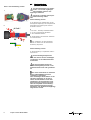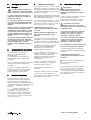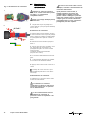
1
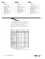
GHG 570 7007 P0001 D/E/F (-) Betriebsanleitung Explosionsgeschützte Y-Verteilerstück/-dose 5-polig (4+PE) / 4-polig (3+PE), GHG 57. Operating instructions Explosion-protected Y-shape distribution box / Y-distributionelement 5-pole (4+PE) / 4-pole (3+PE), GHG 57. Mode d’emploi Distributeur en Y / Boîtier de distribution en Y à 5 pôles (4+PE) / 4 pôles (3+PE), pour atmosphères explosives, GHG 57. &=7HQWRQiYRGNSRXåLWtVLPåHWHY\åiGDW YHVYpPPDWHĜVNpPMD]\FHXSĜtVOXãQpKR ]DVWRXSHQtVSROHþQRVWL&RRSHU&URXVH +LQGV&($*YHYDãt]HPL +$NH]HOpVL~WPXWDWyWD]DGRWWRUV]iJ Q\HOYpQD&RRSHU&URXVH+LQGV&($*FpJ KHO\LNpSYLVHOHWpQLJpQ\HOKHWLPHJ '.0RQWDJHYHMOHGQLQJHQNDQRYHUV WWHVWLO DQGUH(8VSURJRJUHNYLUHUHVKRV'HUHV &RRSHU&URXVH+LQGV&($*OHYHUDQG¡U ,6HGHVLGHUDWHODWUDGX]LRQHGHOPDQXDOH RSHUDWLYRLQXQDOWUDOLQJXDGHOOD&RPXQLWj (XURSHDSRWHWHULFKLHGHUODDOYRVWUR UDSSUHVHQWDQWH&RRSHU&URXVH+LQGV&($* ((QFDVRQHFHVDULRSRGUiVROLFLWDUGHVX UHSUHVHQWDQWH&RRSHU&URXVH+LQGV&($* HVWDVLQVWUXFFLRQHVGHVHUYLFLRHQRWURLGLRPD GHOD8QLRQ(XURSHD /7âLRVQDXGRMLPRLQVWUXNFLMRVLãYHUVWRVƳ-njVǐ JLPWąMąNDOEąJDOLWHSDUHLNDODXWLDWVDNLQJRMH &RRSHU&URXVH+LQGV&($*DWVWRY\EHMHVDYR ãDO\MH (676HGDNDVXWXVMXKHQGLWRPDULLJLNHHOHV Y}LWHNVLGDRPDULLJLVDVXYDVWDVMDRPDVHVW &RRSHU&URXVH+LQGVL&($*HVLQGXVHVW /9âRHNVSOXDWƗFLMDVLQVWUXNFLMXYDOVWVYDORGƗ YDUDWSLHSUDVƯWMXVXYDOVWVDWELOGƯJDMƗ&RRSHU &URXVH+LQGV&($*SƗUVWƗYQLHFƯEƗ ),17DUYLWWDHVVDWlPlQNl\WW|RKMHHQNllQQ|V RQVDDWDYLVVDWRLVHOOD(8QNLHOHOOl7HLGlQ &RRSHU&URXVH+LQGV&($*HGXVWDMDOWDQQH 0-LVWJƫXMLWROEXGDQLOPDQZDOILOOLQJZD QD]]MRQDOLWDJƫKRPPLQJƫDQGLUUDSSUHĪHQWDQW WD &RRSHU&URXVH+LQGV&($*I SDMMLĪKRP *5ǼĮȞȤȡİȚĮıșİȚİIJĮȡĮıȘIJȦȞȠįȘȖȚȦȞȤȡȘıİ ȦȢıİĮȜȜȘȖȜȦııĮIJȘȢǼǼʌȠȡİȚȞĮȗȘIJȘșİȚĮʌȠ IJȠȞǹȞIJȚʌȡȠıȦʌȠIJȘȢ&RRSHU&URXVH +LQGV&($*³ 1/,QGLHQQRRG]DNHOLMNNDQGHYHUWDOLQJYDQ GH]HJHEUXLNVLQVWUXFWLHLQHHQDQGHUH(8WDDO ZRUGHQRSJHYUDDJGELM8Z&RRSHU&URXVH +LQGV&($*YHUWHJHQZRRUGLJLQJ 36HIRUQHFHVViULDDWUDGXomRGHVWDV LQVWUXo}HVGHRSHUDomRSDUDRXWURLGLRPDGD 8QLmR(XURSHLDSRGHVROLFLWDODMXQWRGRVHX UHSUHVHQWDQWH&RRSHU&URXVH+LQGV&($* 3/1LQLHMV]ąLQVWUXNFMrREVáXJLZRGSRZLHGQLHM ZHUVMLMĊ]\NRZHMPRĪQD]DPyZLüZ SU]HGVWDZLFLHOVWZLHILUP\&RRSHU&URXVH +LQGV&($*QDGDQ\NUDM 6(Q|YHUVlWWQLQJDYGHQQDPRQWDJHRFK VN|WVHOLQVWUXNWLRQWLOODQQDW(8VSUnNNDQYLG EHKRYEHVWlOODVIUnQ(U&RRSHU&URXVH +LQGV&($*UHSUHVHQWDQW 6.7HQWRQiYRGQDREVOXKX9iPYR9DãRP URGQRPMD]\NXSRVN\WQH]DVW~SHQLHVSRORþQRVWL &RRSHU&URXVH+LQGV&($*YR9DãHMNUDMLQH 6/21DYRGLOD]DXSRUDERY9DãHPMH]LNX ODKNR]DKWHYDWHSULSULVWRMQHP]DVWRSQLãWYX SRGMHWMD&RRSHU&URXVH+LQGV&($*Y9DãL GUåDYL Inhalt: 1 2 3 4 5 6 6.1 7 8 9 10 Contents: Inhalt................................... Kabelliste............................ Uhrzeiten ........................... 2 2 3 Technische Angaben.......... Sicherheitshinweise............ Normenkonformität............. Ausführung ..... Verwendung/ Eigenschaften..................... Elektrischer Anschluss....... Stecken / trennen Elektrischer Anschluss......... Inbetriebnahme................... Wartung / Reparatur............ Entsorgung........................... 4 5 5 5 5 5 6 7 7 7 7 Contenu: Contents .............................. 2 Cablelist ............................... 2 Time Code ........................... 3 1 2 3 4 5 6 6.1 7 8 9 10 Technical data ..................... Safety instructions ............... Conformity with standards . Design .................................. Use / Properties .................. Electrical connection ........... Connestion/disconnection .. Connection with cable ......... Putting into operation ........... Maintenance/Servicing ....... Disposal ............................... 8 9 9 9 9 9 10 11 11 11 11 1 2 3 4 5 6 6.1 7 8 9 10 Kabelliste Cable list Câble liste Geprüfte Kabeltypen zur Verwendung am Ex-Link Stecksystem IP X8 bei 2 m Wassertiefe und eine Stunde untergetaucht. Kind of cables which can be used with the ex-link connector IP X8 protection at 2 m water depht an one hour flooded. Types par câble examinés immergé visant l’utilisation à l’Ex-Link système de mise IP X8 avec 2 m profondeur de l’eau et une heure. Kabeltyp kind of cable Kabel cable d in mm Ölflex classic 100 Ölflex classic 400 Ölflex classic 110 H07 BQ-F 3G1,5 H07 BQ-F 5G1,5 JZ-500 Y-JZ RD-Y (ST) Y blau JE-LiYCY NYM 3x1,5 NYM 5x1,5 JE-Y(ST)Y HO7-RN-F 3G1,0 HO7-RN-F 3G1,0 HO7-RN-F 3G1,0 HO5-RN-F 3G1,0 HO5-RN-F 3G1,0 HO5-RN-F 3G1,0 HO5-RN-F 3G1,0 Silflex SiHf 8 10 5,7 8,3 10,5 9 7,8 6,3 6,5 9,5 10,5 6,6 8,8 10 11 6,6 7 8,2 10 7,8 Schutzart type of protection IPX6 IPX8 x x x x x x x x x x x x x x x x x x x x Nicht aufgeführte Kabeltypen wurden nicht geprüft. Ohter kinds of kabel are not testet. Des types par câble spécifiés n’ont pas été examinés. 2 Cooper Crouse-Hinds GmbH Contenu ................................. Câble liste .............................. Temps codage ....................... 2 2 3 Caractéristiques techniques Consignes de sécurité. ......... Conformité avec les normes . Domaine d’utilisation ............. Utilisation/Propriétés ............. Branchement électrique ........ Branchement/ Debranchement .................... Raccordement électrique ..... Mise en service ..................... Maintenance / Réparation .... Elimination .............................. 12 13 13 13 13 13 14 15 15 15 15 Uhrzeitenübersicht Time Code Temps codage Um den Code (Uhrzeit) der Kupplung / des Steckers festzustellen, die Führungsnase / Nut nach unten (6h) drehen. Alle weiteren Codes resultieren aus dieser Lage. To climp the code (timecode) fo the coupler / plug the leader nut is turned down. All other codes are results of this position. Pour constater le code (heure) de l'embrayage/prise de courant que le nez de conduite/cannelure tourne vers le bas (6h). Tous les autres codes résultent de cette situation. Les anneaux de couleurs beiligende devraient être utilisés au marquage du code respectif. Kodierung der Steckverbindung / Coding of connections / Codification des connexions mâles-femelles Spannung Voltage Tension Ethernet Bus Polzahl Code Kupplung / Flanschsteckdose Stecker / Gerätestecker No.of pol. Code Coupler / Flange socket Plug / Inlet Nombre Code Prolongateur / Prise à bride Fiche / socle connecteur de pôles 4 4 110-130V AC 2 + PE 4 + PE 230-250V AC 2 + PE 24V DC 4 4 2 1 1 2 3 4 4 3 2h 2 1 1 2 3 (N) 3 (N) 2 PE 1 (L1) 5h 3 (-) 1 (-) PE 4 (+) 2 gelb yellow 3 PE 4 2 grün / rot green / red 1 2 3 (N) 3 (N) 2 1 (L1) 1 PE 2 (+) PE 1 (L1) 2 (+) 1 4 (-) 3 3 6h 1 PE 10 h PE 4 (-) 1 4 2 3 PE 2 PE 3 1 2 12 h 2 1 rot red grau grey 8h 3 2 + PE PE 2 (+) 3 24V AC grün green 4h 4 230-250V AC 4 + PE* 3 3 1h 1 (L1) 24V DC 4 Vorgeschlagener Farbring Code / suggestet rubber colour code / blau blue ohne Ring without ring * mit PE-Bügel / with PE clamp / avec étrier PE Cooper Crouse-Hinds GmbH 3 1 Maßbild Y-Verteilerstück Gerätekennzeichnung nach 94/9/EG: Explosionsschutz: EG-Baumusterprüfbescheinigung: Bemessungsspannung: mit Crimp- und Käfigzugfeder Anschluss Bemessungsstrom: mit Klemmenblock ohne Klemmenblock Max. Vorsicherung ohne therm. Schutz: Max. Vorsicherung mit therm. Schutz Schaltvermögen nach EN 61 984: 200 74 111 42 77 134 Maßbild Y-Verteilerdose 74 Technische Angaben II 2G II 2D IP66 T 80° C/ T 95° C EEx de IIC T6/T5 (siehe Tabelle 1) PTB 05 ATEX 1084 AC- bis 250 V, 50/60 Hz DC- bis 60 V AC - max. 9,3 A DC - max. 2,5 A AC - max. 10,0 A DC - max. 2,5 A 10 A 20 A gL AC - 250 V / 10,0 A DC - 60 V/ 2,5 A Schaltvermögen nach EN 60 947-4: AC 3 - 250 V / 1,0 A DC 3 - 60 V/ 0,5 A Zulässige Umgebungstemperatur 1): -55° C bis +75° C (siehe Tabelle 1) Zul. Lagertemperatur in Originalverpackung: -55° C bis +80° C Schutzart nach EN 60529/IEC 529: IP 66/ IP 682) bei geschlossenen und gesicherten Schutzkappen sowie ordnungsgemäß gesteckten und gesicherten Komponenten. Schutzklasse nach EN 60598/IEC 598: II - wird von den Kunststoff Geräten erfüllt Leitungseinführung: Listenausführung Ø 4 - 7,5 mm Ø 7,5 - 11 mm Anschlussklemme / Kontakt: Querschnitt feindrähtig 0,34 mm² bis 1,50 mm² feinstdrähtig 0,34 mm² bis 0,75 mm² Prüfdrehmomente: Kunststoff Überwurfmutter 2,5 Nm Schutzkappe 2,5 Nm Druckschraube mit Zugentlastung Ø 4 - 7,5 mm 2,5 Nm Ø 7,5 - 11 mm 2,5 Nm Arretierungsschrauben 1,0 Nm Gewicht: Kunststoff Y-Verteilerstück GHG 57 ca. 290 g Y-Verteilerdose GHG 57 ca. 190 g 42 2) Besondere Prüfbedingungen: 2 m Wassersäule, 1 h Dauer, andere Prüfbedingungen bedürfen der besonderen Vereinbarung. Angaben zur IP-Schutzart siehe Kabelliste . Tabelle 1 Belastbarkeit bei Klemmenanschluss Typ GHG 57_1/2 (mit Leitungseinführung) max. Umgebungstemperatur Temperaturklasse I zul. bei 0,5 mm² I zul. bei 0,75 mm² I zul. bei 1,0 mm² I zul. bei 1,5 mm² max. Oberflächentemperatur Ta = 40 °C T6 4,3 A 4,8 A 5,4 A 8,0 A 61 °C T5 5,0 A 5,8 A 6,5 A 9,3 A 71 °C Ta = 55 °C T6 3,3 A 3,6 A 4,1 A 6,0 A 69 °C T5 4,3 A 4,8 A 5,3 A 8,0 A 76 °C Ta = 75 °C T6 1,3 A 1,5 A 1,6 A 2,5 A 79 °C T5 3,0 A 3,2 A 3,6 A 5,3 A 86 °C Tabelle 2 Belastbarkeit bei Crimpanschluss mit 2 Mantelleitungen 4 x 1 mm2 Typ GHG 57_1/2 (mit Leitungseinführung) max. Umgebungstemperatur Temperaturklasse zulässiger Strom I zul. max. Oberflächentemperatur Ta = 40 °C T6 T5 9,8 A 10 A 71 °C 84 °C Ta= 55 °C T6 7,7 A 74 °C T5 9,8 A 86 °C Ta= 75 °C T6 3,0 A 79 °C T5 6,8 A 91 °C Ta= 55 °C T6 7,5 A 69 °C T5 9,5 A 76 °C Ta= 75 °C T6 2,8 A 78 °C T5 6,6 A 86 °C Tabelle 3 Belastbarkeit Typ GHG 57_8/9 (Stecker - Kupplung- Ausführung) max. Umgebungstemperatur Temperaturklasse zulässiger Strom I zul. max. Oberflächentemperatur 4 Cooper Crouse-Hinds GmbH Ta = 40 °C T6 T5 9,5 A 10 A 61 °C 69 °C 2 Sicherheitshinweise 2.1 Grundsatz Die Y-Verteilerstück/-dose sind zum Einsatz in explosionsgefährdeten Bereichen der Zonen 1, Zone 2 und Zone 21, Zone 22 gemäß IEC 60079-10 und IEC 60079-14 geeignet! Informationen der zulässigen Elektrokabel sind in der Tabelle auf Seite 2 aufgeführt. Das an die Steckverbindung angeschlossene Gerät muss für die anliegende Netzspannung Zielgruppe dieser Anleitung sind geeignet sein. Elektrofachkräfte und Unterwiesene Sie werden auch zum Schnellanschluss von Personen in Anlehnung an die explosionsgeschützten elektrischen BetriebsIEC 60079-14. Die Y-Verteiler nicht miteinander baumartig mitteln im Ex- und Industriebereich verwendet. zusammenstecken. Die auf den Geräten angegebene Das am Y-Verteilerstück/-dose angeTemperaturklasse und Zündschutzart ist schlossene Betriebsmittel muss für die Weitere Informationen über den Steckzu beachten. anliegende Netzspannung geeignet sein. verbinder „eXLink“ finden Sie auch in der Die Steckverbindung ist nicht für den Bedienungsanleitung Einsatz im explosionsgefährdeten Bereich Die auf dem Y-Verteilerstück/-dose GHG 570 7001 P 0001. angegebene Temperaturklasse und der Zone 0 und Zone 20 gemäß Diese erhalten Sie bei Ihrer zuständigen Zündschutzart beachten. IEC 60079-10 geeignet. Cooper Crouse-Hinds Niederlassung oder auf unserer Internetseite. Die Anforderungen der EN 50281-1-2, u.a. Steckverbindung nur in technisch einwandfreiem Zustand sowie bestimmungs- in Bezug auf übermäßige Staubabgemäß, sicherheits- und gefahrenbewusst lagerungen und Temperatur, sind vom Anwender zu beachten. unter Beachtung dieser Montage- und i Betriebsanleitung montieren und betreiben. Beachten Sie die nationalen Sicherheitsund Unfallverhütungsvorschriften und die nachfolgenden Sicherheitshinweise in dieser Betriebsanleitung, die wie dieser Text in Kursivschrift gefasst sind! 3 Normenkonformität Die Y-Verteilerstück/-dose sind gemäß DIN EN ISO 9001 entwickelt, gefertigt und geprüft worden. Sie entsprechen den in der Konformitätserklärung aufgeführten Normen. 94/9 EG: Geräte und Schutzsysteme zur bestimmungsgemäßen Verwendung in explosionsgefährdeten Bereichen. Weitere Anforderungen wie die Richtlinie "Elektromagnetische Verträglichkeit (89/336/ EWG)" werden von dem Y-Verteilerstücken/dosen erfüllt. 4 Ausführung Die eingesetzten Gehäusematerialien einschließlich der außenliegenden Metallteile bestehen aus hochwertigen Werkstoffen, die einen anwendungsgerechten Korrosionsschutz und Chemikalienresistenz in "normaler Industrieatmosphäre" gewährleisten: - schlagfestes Polyamid Bei einem Einsatz in extrem aggressiver Atmosphäre, können Sie zusätzliche Informationen über die Chemikalienbeständigkeit der eingesetzten Kunststoffe, bei Ihrer zuständigen Cooper Crouse-Hinds Niederlassung erfragen. 5 Verwendung / Eigenschaften Y-Verteilerstück/-dose GHG 57. dienen zur Stromversorgung von standortvariablen VorOrt-Steuerungen, elektrischen Anlagen sowie von beweglichen Maschinen und Antrieben in explosionsgefährdeten Bereichen. Y-Verteilerstück/-dose unter Last nur mit den Werten der Technischen Daten betreiben. Die Verantwortung hinsichtlich bestimmungsgemäßer Verwendung der Steckverbindung unter Bezugnahme der in dieser Montageund Betriebsanleitung vorhandenen Rahmenbedingungen (Technischen Daten) liegt allein beim Betreiber. Y-Verteilerstück/-dose vor Inbetriebnahme entsprechend der im Abschnitt 8 genannten Anweisungen prüfen. Keine Veränderungen bzw. Umbauten an der Y-Verteilerstück/-dosen vornehmen. Jede andere Verwendung ist nicht bestimmungsgemäß. COOPER Crouse-Hinds übernimmt keine Haftung für Schäden, die aus nicht bestimmungsgemäßer Verwendung entstehen. 6 Elektrischer Anschluss Warnung: Lebensgefahr durch Stromschlag! Der elektrische Anschluss der Y-Verteilerdose darf nur durch eine Elektrofachkraft erfolgen. Für den Betrieb der Y-Verteilerstück/-dose sind die relevanten nationalen Vorschriften sowie die allgemeinen anerkannten Regeln der Technik maßgebend. Die Steckverbindungskomponenten nach dem Trennen mit der Schutzkappe verschließen. Dabei ist auf den korrekten Verschluss zu achten, da sonst die Mindestschutzart und der Explosionsschutz nicht mehr gewährleistet sind. Nicht benutzte Komponenten sind mit der Schutzkappe verschlossen aufzubewahren. Cooper Crouse-Hinds GmbH 5 6.1 Bild 6.1 Steckverbindung stecken Steckverbindung stecken / trennen Die Flanschsteckdosen und Gerätestecker nur mit den zugehörigen unbeschädigten Steckern und Kupplungen betreiben. 1 Auf gleiche Codierung (Uhrzeit) der Steckverbindung achten. Steckverbindung stecken 1. Der Stecker bzw. Gerätestecker mit der Führungsnase lagerichtig in die entsprechende Führungsnut der Kupplung bzw. Flanschsteckdose stecken. 2 „klick“ 1 2 2. 1. Bis zum 1. Anschlag zusammenstecken. 2. Um 30° gegeneinander Verdrehen. 3. Ganz zusammenstecken. 3 3. Überwurfmutter des Steckers andrücken und festschrauben. 3 30° 2 1 Durch Festdrehen der Überwurfmutter wird der IP Schutz und die mechanische Verbindung hergestellt. 3 2 1 Steckverbindung trennen 1. Steckverbindung in umgekehrter Reihenfolge trennen. Steckverbindungskomponenten nach dem Trennen mit der Schutzkappe verschließen, um die Mindestschutzart herzustellen. Bei nicht korrektem Stecken der Steckverbindungskomponenten ist der Explosionsschutz nicht mehr gewährleistet. Nach einem Kurzschluss im Stromkreis ist die Funktionsfähigkeit der Steckverbindung zu überprüfen. Nach mehrmaligen Kurzschlüssen ist die druckfeste Kapselung an den Steckstiften und Steckbuchsen nicht mehr gewährleistet. Da die Kapselung nicht augenscheinlich geprüft werden kann, muss die komplette Steckverbindung (Flanschsteckdose/Stecker bzw. Kupplung/Stecker oder Gerätestecker/Kupplung) ausgetauscht werden. 6 Cooper Crouse-Hinds GmbH 7 Elektrischer Anschluss 9 Wartung / Reparatur Warnung: Lebensgefahr durch Stromschlag! Steckverbindung vor der Wartung / Reparatur stromlos schalten. 7-1. Y-Verteilerdose Typ GHG 57_1/2 (mit Leitungseinführung und Klemmstein) 8 - Druckstück 9 - Schraube M4 1 - Gehäuse 2 - Verschlussteil 6 - Zugentlastung 7 - Dichtung 5 - Schirmblech 3 - Verschlussschraube 11 - Entriegelungswerkzeug (z.B. Schraubendreher 2,5x75) 12 Öffnung für Zugfederentriegelung 7. 1 Y-Verteilerdose öffnen (Fig. 7-1) 7 . 3 Anschlussleiter lösen (Fig. 7-1) 1. 2. 3. Die zwei Verschlussschrauben (3) lösen. Verschlussteil (2) aus Gehäuse (1) herausziehen. Schraube (9) lösen und Drückstück (3) abnehmen. Damit der IP-Schutz erhalten bleibt dürfen an den Adapter immer nur Leitungen des gleichen Typ, Adernanzahl und Querschnitt angeschlossen werden. 4. Leitungen einführen. Der Durchmesser der Zugentlastungen (6) und Dichtungen (7) müssen an den Leitungsdurchmesser angepasst sein. 7.2 Anschlussleiter anschließen (Fig. 7-1) Für die Wartung / Reparatur sind die relevanten nationalen Vorschriften sowie die allgemein anerkannten Regeln der Technik maßgebend. Bei der Wartung vor allem die Teile, von denen die Zündschutzart abhängt prüfen. /z.B. Unversehrtheit des Gehäuse der Dichtungen, der Steckerstifte, Steckbuchsen). Zur Wartung / Reparatur nur Originalteile des Herstellers verwenden. 4 - Klemmenblock 10 - Leiter Sicherstellen, dass beim Öffnen der Geräte keine explosive Umgebungsatmosphäre vorhanden ist. Den Anschlussleiter wie abgebildet mit einem geeigneten Schraubendreher entriegeln. 7 . 4 Y-Verteilerdose schließen Alle Fremdkörper aus dem Gerät entfernen. Keine Leiter beim zusammenschrauben quetschen. 1. Zugentlastung (6) mit Leitungen und Druckstück (8) lagerichtig montieren. Schraube (9) bis zur Zugentlastung- und Dichtwirkung festdrehen. 2. Verschlussteil (2) lagerichtig montieren. Verschlussschrauben (3) festdrehen. Bei übermäßigem Anziehen kann die Beschädigte Steckerstifte und Steckbuchsen sofort wechseln oder Steckverbindung an den Hersteller zur Reparatur schicken. Bei Schäden an der druckfesten Kapselung ist nur ein Austauschen zulässig. Im Zweifelsfall die Steckverbindung an den Hersteller zur Reparatur schicken. Reparaturen, die den Explosionsschutz betreffen, dürfen nur vom Hersteller oder einer qualifizierten Elektro-Fachkraft in Übereinstimmung mit nationalen geltenden Regeln durchgeführt werden. Umbauten oder Änderungen an den Steckverbindungen sind nicht festgelegt. Wartungsintervalle sind vom Betreiber der Steckverbindung selbst festzulegen. Zu beachten ist: -> Alle Teile der Steckverbindung auf Beschädigung prüfen. -> Keine beschädigten Teile der Steckverbindung reparieren. -> Beschädigte Teile bzw. gesamte Steckvorrichtung wechseln. 10. Entsorgung Schutzart beeinträchtigt werden Die Isolation der Anschlussleitungen -> Steckverbindung nach den örtlichen muss bis an die Klemme heranreichen. Der (Prüfdrehmoment siehe Techn. Daten) . Vorschriften sachgerecht entsorgen. Leiter selbst darf nicht beschädigt sein. Die minimal und maximal anschließbaren Programmänderungen und -ergänzungen Leiterquerschnitte beachten (siehe 8 Inbetriebnahme sind vorbehalten. technische Daten). Vor Inbetriebnahme des Betriebsmittels: Die ordnungsgemäß abisolierten Anschluss-> Auf Beschädigungen prüfen. leitungen der Kabel unter Berücksichtigung -> Prüfungen gemäß nationalen Bestimmungen einschlägiger Vorschriften anschließen. durchführen. -> Funktion in Übereinstimmung mit der Die Zugfederklemmen sind für den Anschluss Betriebsanleitung und anderen anwendbaren von Kupferleitern ausgelegt. Bestimmungen überprüfen. Bei der Verwendung von mehr- oder feindrähtigen Anschlusskabel /-leitungen die Aderenden entsprechend den geltenden nationalen und internationalen Vorschriften behandeln (z.B. Verwendung von Aderendhülsen). Cooper Crouse-Hinds GmbH 7 1 Technical Data 200 Dimensions drawing Y-shape distribution box 74 111 42 77 134 Dimensions drawing Y-distribution element 74 Apparatus marking to 94/9/EC: II 2G II 2D IP66 T 80° C/ T 95° C Explosion protection: EEx de IIC T6/T5 (see table 1) EC-Type Examination Certificate: PTB 05 ATEX 1084 Rated voltage for crimp- and spring cage terminal connection AC- up to 250 V. 50/60 Hz DC- up to à 60 V Rated current: with terminal block AC - max. 9.3 A DC - max. 2.5 A without terminal block AC - max. 10.0 A DC - max. 2.5 A Max. back-up fuse without thermal protection: 10 A Max. back-up fuse with thermal protection 20 A gL Switching capacity EN 61 984: AC - 250 V / 10.0 A DC - 60 V/ 2.5 A Switching capacity EN 60 947-4: AC 3 - 250 V / 1.0 A DC 3 - 60 V/ 0.5 A Permissible ambient temperature: 1): -55° C bis +75° C (see table 1) Perm. storage temperature in original packaging: -55° C bis +80° C Degree of protection to EN 60529/IEC 529: IP 66/ IP 682) when the protective caps have been closed and safeguarded and the components connected and safeguarded correctly Insulation class to EN 60598/IEC 598: II - fulfilled by metal apparatus Cable entry: catalogue version Ø 4 - 7.5 mm Ø 7.5 - 11 mm Terminals cross section fine wire 0.34 mm² to 1.50 mm² multi wire 0.34 mm² to 0.75 mm² Test torques Cap nut 2.5 Nm Protective cap 2.5 Nm Pressure screw with strain relief Ø 4 - 7.5 mm 2.5 Nm Ø 7.5 - 11 mm 2.5 Nm Locking screws 1.0 Nm Weight: Moulded plastic Y-shape distribution box GHG 571 3. ca. 290 g Y-distribution element GHG 571 7. ca. 190 g 42 2) special testconditons: 2m water column, 1 h duration, other test conditions must be agreed to. Specifications to degree of protection see cable list. (see appendix) Table 1 Current carrying capacity with terminal connection type GHG57_1/2 (with cable entry) max. ambient temperature Temperaturklasse I app. by 0.5 mm² I app. by 0.75 mm² I app. by 1.0 mm² I app. by 1.5 mm² max. surface temperature Ta = 40 °C T6 4.3 A 4.8 A 5.4 A 8.0 A 61 °C T5 5.0 A 5.8 A 6.5 A 9.3 A 71 °C Ta= 55 °C T6 3.3 A 3.6 A 4.1 A 6.0 A 69 °C T5 4.3 A 4.8 A 5.3 A 8.0 A 76 °C Ta= 75 °C T6 1.3 A 1.5 A 1.6 A 2.5 A 79 °C T5 3.0 A 3.2 A 3.6 A 5.3 A 86 °C Table 2 Current carrying capacity with crimp connection 2 cables 4 x 1 mm² type GHG57_1/2 (with cable entry) max. ambient temperature temperature class permissible current I max. surface temperature Ta = 40 °C T6 T5 9.8 A 10 A 71 °C 84 °C Ta= 55 °C T6 7.7 A 74 °C T5 9.8 A 86 °C Ta= 75 °C T6 3.0 A 79 °C T5 6.8 A 91 °C T5 9.5 A 76 °C Ta= 75 °C T6 2.8 A 78 °C T5 6.6 A 86 °C Table 3 Current carrying capacity type GHG57_1/2 (Plug and connector design) max. ambient temperature temperature class permissible current I max. surface temperature 8 Cooper Crouse-Hinds GmbH Ta = 40 °C T6 T5 9.5 A 10 A 61 °C 69 °C Ta= 55 °C T6 7.5 A 69 °C 2 2.1 Safety instructions Principle Operations shall be carried out by electricians and suitably personnel trained in hazardous area with knowledge of increased safety explosion protection in accordance with IEC 60079-14 The temperature class and explosion group marked on the terminal boxes have to be observed. The plug and socket system is not suitable for Zone 0 and Zone 20 azardous areas accordance with IEC 60079-10. These assembly and operating instructions shall be observed when installing and operating the plug and socket connector system. It shall only be used in a technically perfect state and in accordance with the intended purpose while paying attention to the particular safety and hazard aspects. The plug and socket systems GHG 57. are intended for use in potentially explosive atmospheres in Zones 1, Zones 2 and Zones 21, Zones 22 in accordance with IEC 60079-10 and IEC 60079-14! They are also used for the quick connection of explosion-protected electrical apparatus in potentially explosive atmospheres and industrial areas The apparatus connected to the plug shall be suited for the mains voltage being applied. The temperature class and type of protection stated on the apparatus shall be observed. 3 Plug and socket systems shall be checked in accordance with Section 8 of the named instructions, before being put into use. 94/9 EC: Equipment and protective systems intended for use in potentially explosive atmospheres. The plug and socket system also fulfil further requirements such as those of directive on electromagnetic compatibility (89/366/EEC). 4 Design The enclosure materials employed, including the exterior metal parts, are made of highquality materials which ensure a corrosion protection and resistance to chemical substances corresponding to the requirements in a „normal industrial atmosphere“: impact resistant polyamide In case of use in an extremely aggressive atmosphere, please refer to your "COOPER Crouse Hinds" agency. 5 Use / Properties The Y-Verteilerstück/-dose GHG 57. are used for the power supply of portable, local controls, electrical installations and portable electric machines and drives in potentially explosive atmospheres The Y-adapters shall not be directly coupled together. iFurther informations about the plug and socket system „exLink“ are written in the Operting instruction „GHG 570 7001 P 0001.“too. For this, please refer to your „COOPER Crouse-Hinds“agency. The plug and socket system may only be operated and disconnected under load acc. to the technical data. The sole responsibility with respect to the suitability and proper use of the plug and socket systems with regard to the basic requirements of these instructions (see Technical Data) lies with the operator. The Y-Verteilerstück/-dose is conform to the standards specified in the EC-Declaration of conformity. It has been designed, manufactured and tested according to the state of the art and to DIN EN ISO 9001 Information on the permissible connection leads can be found in the list of cables on page 2. The requirements of the EN 50281-1-2 regarding excessive dust deposits and temperature to be considered from the user The national safety rules and regulations for the prevention of accidents, as well as the safety instructions included in these operating instructions, that, like this text, are set in italics, shall be observed! Conformity with standards Unused components are to be kept sealed with the protective cap. Modifications or changes to the design of the plug and socket systems are not permitted. Applications other than described are not permitted without COOPER CROUSEHINDS´s prior written consent. CCH takes no responsibility for damages causedby incorrect use. 6 Electrical connection Warning: Electric shock hazard! Electrical connection may only be made by an electrician. The relevant national regulations and the generally recognized rules of engineering apply for the installation and operation. When opened, the live plug and socket system components shall be sealed immediately after disconnection using the protective cap. Here it is necessary to ensure that it is closed correctly, otherwise the minimum degree of protection and the explosion protection are no longer guaranteed. Cooper Crouse-Hinds GmbH 9 6.1 Fig 6.1 Connection of plug and socket Connection / disconnection of plug and socket The flange sockets and inlets shall only be operated with the associated, undamaged plugs and couplers. 1 Attention shall be paid that the coding (time setting) of the plugs and sockets is the same. Connecting plug and socket 1. Insert the plug or inlet with the guide lug in the correct position into the respective keyway of the coupler or flange socket. 2 „ cl i c k “ 1 2 2. 1. Insert until 1st stop is reached. 2. Turn plug or inlet through ca. 30° in relation to the coupler or flange socket until the stop is reached. 3. Join plug and socket completely. 3 30° 3 2 1 3. Press the coupling nut of the plug on and screw it tight. The IP degree of protection and the mechanical connection are established by tightening the coupling nut. Disconnecting plug and socket 1. To disconnect plug and socket, carry out the above actions in the reverse order. When opened, the live plug and socket system components shall be sealed immediately after disconnection using the protective cap. The explosion protection is no longer guaranteed if the plug and socket components are not inserted correctly. After a short circuit, the plug and socket systems shall be checked to ensure that they function correctly. As, after several short circuits, the flameproof encapsulation of the plug pins and contacts sockets is no longer guaranteed, the complete plug and socket system (flange socket/plug or coupler/plug or inlet/coupler) shall be replaced. 10 Cooper Crouse-Hinds GmbH 7 Connection with cable 9 7-1. Y-adaptor Type GHG57_1/2 (with cable entry and terminal block) 8 - Pressure piece 9 - screw M4 1 - Enclosure 2 - Enclosure cover 6 - Strain relief 7 - Seal 5 - Screen shroud 3 - Cover screw 4 - Terminal block 11 - Releasing tool (z.B. scew-driver 2,5x75) 10 - Connection wire 12 - Spring cage terminal Maintenance / Servicing Warning: Electric shock hazard! Isolate plug and socket connector before carrying out maintenance / repair work. When opening the apparatus, ensure that no potentially explosive atmosphere is present. The valid national regulations for the servicing / maintenance of electrical apparatus for use in potentially explosive atmospheres shall be observed. Only original manufacturer parts shall be used for carrying out repairs. In the event of damage to the plug pins or contact sockets, these components shall be replaced immediately or the respective apparatus shall be sent to the manufacturer for repair. In the event of damage to the flameproof encapsulation, the apparatus has to be replaced. If in doubt, send the plug and socket connector back to the manufacturer for repair. Repairs that affect the explosion protection may only be carried out by the manufacturer or by a qualified electrician in compliance with the respective national regulations. 7.1 Opening the Y-adapter (Fig. 7-1) 7 . 3 Unconnecting conductors (Fig. 7-1) 1. Loosen the two locking screws (3). 2. 3. Pull out locking cap(2) of enclosure(1) . Loosen screw (9) and take down pressure piece (3). In order to maintain the IP rating only cables of the same type, cores and cross section shall be connected 4. Cable installation. The diameter of the strain relief clamp (6) must be adapter to suit the seal (7). 7.2 Connecting conductors (Fig. 7-1) Release the wire with an appropriate tool (screwdriver) as shown. 7.4 Closing the Y-adapter Any foreign matter is to be removed from the apparatus. 1. mount the strain relief clamp (6) with cable and seal in the correct position. Tighten screw (9) to ensure strain relief and required seal. 2. Mount enclosure cover (2) correctly in position.Tighten cover screw (3) Overtightening might impair the The insulation of the conductor shall reach up to the plug pins. The conductor must not be damaged. The connectible min. and max. conductor cross-sections will have to be observed. The insulation of the conductors shall reach up to the terminal. The conductor itself shall not be damaged. The properly bared conductors of the cables shall be connected, taking into account the respective regulations. Modifications or changes to the design of the plug and socket systems are not permitted. The intervals between servicing are to be stipulated by the operator of the plug and socket connector. Please note: -> Check all parts of the plug and socket system for damage. -> Do not repair damaged parts of the plug and socket system. -> Damaged parts and/or entire of the plug and socket system change. 10. Disposal protection category. -> Dispose of the plug and socket correctly in accordance with the local regulations. 8 We reserve the right to make changes and additions to the product range. Putting into operation Before putting into operation observe: - the correct insterlation of the apparatus in acc. with: - the operating instructions - instruction of use - connection documentation - tests acc. the national directives. The supply terminals are designed for the connection of copper conductors. If multi- or fine-wire connecting cables are used, the wire ends will have to be handled in acc. with the Incorrect installation and use of the applicable national and international rules terminal boxes can invalidate the (e. g. use of ferrules). guarantee. Cooper Crouse-Hinds GmbH 11 1 Dimensions Distributeur en Y Identification de l’appareil suivant 94/9/CE: Mode de protection: Attestation d’examen CE: Tension nominale: avec connexion à ressort de rappel à cage d’écureuil et ressort à crampon 200 74 111 II 2G II 2D IP66 T 80° C/ T 95° C EEx de IIC T6/T5 (voir tableau 1) PTB 05 ATEX 1084 AC- jusqu’à 250 V, 50/60 Hz DC- jusqu’à 60 V Courant de mesure : avec bornier: sans bornier: sans protection thermique : avec protection thermique : Puissance de coupure EC 61 984: 42 77 134 Dimensions Boîtier de distribution en Y 74 Caractéristiques techniques 42 AC - maxi. 9,3 A DC - maxi. 2,5 A AC - maxi. 10,0 A DC - maxi. 2,5 A 10 A 20 A gL AC - 250 V / 10,0 A DC - 60 V/ 2,5 A Puissance de coupure EC 60 947-4: AC 3 - 250 V / 1,0 A DC 3 - 60 V/ 0,5 A Température ambiante admissible 1): -55° C á +75° C (voir tableau 1) Température de stockage dans l’emballage original:: -55° C á +80° C avec protection thermique : EN 60529/IEC 529: IP 66/ IP 682) ndice de protection selon EN 60529/CEI 529: obturateurs fermés et sécurisés, et composants correctement enfichés et Indice de protection selon EN 60598/IEC 598: II - pour les appareils en matière plastique Entrée de câble: (modèle de liste) Ø 4 - 7,5 mm Ø 7,5 - 11 mm Borne de raccordement / contact : Section câble fin 0,34 mm² á 1,50 mm² câble ultra-fin 0,34 mm² á 0,75 mm² Torques d'essai: Plastique Collerette de fixation 2,5 Nm Obturateur 2,5 Nm Vis de pression avec décharge de traction Ø 4 - 7,5 mm 2,5 Nm Ø 7,5 - 11 mm 2,5 Nm Vis d’arrêt 1,0 Nm Poids : Plastique Distributeur en Y GHG 571 3. env. 290 g Boîtier de distribution en Y GHG 571 7. env. 190 g 1) Conditions d’essai particulières : colonne d’eau de 2 m, durée 1 h. D’autres conditions d’essai nécessitent un accord spécifique. Données sur l’indice de protection IP, voir liste de câbles. Tableau 1 Capacité de charge à la borne de type GHG 57_1/2 (avec entrée de câble) Température ambiante maxi Classe de température I adims 0,5 mm² I adims 0,75 mm² I adims 1,0 mm² I adims1,5 mm² Température de surface maxi Ta = 40 °C T6 4,3 A 4,8 A 5,4 A 8,0 A 61 °C T5 5,0 A 5,8 A 6,5 A 9,3 A 71 °C Ta= 55 °C T6 3,3 A 3,6 A 4,1 A 6,0 A 69 °C T5 4,3 A 4,8 A 5,3 A 8,0 A 76 °C Ta= 75 °C T6 1,3 A 1,5 A 1,6 A 2,5 A 79 °C T5 3,0 A 3,2 A 3,6 A 5,3 A 86 °C Tableau 2 Capacité de charge pour les raccords à sertir à 2 conducteurs gainés 4 x 1 mm 2 de type GHG 57_1/2 (avec entrée de câble) Température ambiante maxi Classe de température Courant admis, I admis Température de surface maxi Ta = 40 °C T6 T5 9,8 A 10 A 71 °C 84 °C Ta= 55 °C T6 7,7 A 74 °C T5 9,8 A 86 °C Ta= 75 °C T6 3,0 A 79 °C T5 6,8 A 91 °C Ta= 55 °C T6 7,5 A 69 °C T5 9,5 A 76 °C Ta= 75 °C T6 2,8 A 78 °C T5 6,6 A 86 °C Tableau 3 Capacité de charge de type GHG 57_8/9 (modèle fiche - coupleur) Température ambiante maxi Classe de température Courant admis, I admis Température de surface maxi 12 Cooper Crouse-Hinds GmbH Ta = 40 °C T6 T5 9,5 A 10 A 61 °C 69 °C 2 Consignes de sécurité 2.1 Principe 5 Utilisation / Propriétés 6 Branchement électrique Les Y-Adaptateur GHG 57. servent à l’aliAvertissement : mentation en courant de commandes in situ, d’installations électriques ainsi que de machines Danger de mort par électrocution ! Ce mode d’emploi s’adresse aux et entraînements mobiles dans des secteurs Le branchement électrique du Yélectriciens et personnes initiées Adaptateur est réservé à un électricien sur base de la norme CEI 60079-14. exposés aux explosions. confirmé. Ils sont également utilisés pour le raccorde-ment Le groupe d’explosion et la classe de rapide d’appareillage électrique anti-déflagrant La mise en service duY-Adapteur est régie température marqués sur les appareils par les prescriptions nationales dans les domaines industriel et Ex. devront être respectés. correspondantes de même que par les Les connexions par fiches GHG 57. convien- règles techniques générales reconnues. Le connecteur n’est pas conçu pour être nent pour une utilisation dans les secteurs utilisé dans les atmosphères explosibles exposés aux explosions des zones 1, zones 2 des zones 0 et 20 conformément à CEI Les éléments de connexion selon CEI 60079-10 et CEI 60079-14! 60079-10. conducteurs de tension à l’état ouvert doivent être fermés avec le capuchon dès Monter et utiliser le connecteur seulement L’appareillage électrique relié au le débranchement. connecteur doit être adapté à la tension s’il présente un état technique parfait, du réseau. conformément à sa destination, en étant A cet effet il faut veiller à une fermeture conscient des risques et des mesures de correcte sinon le type de protection Observez la classe de température et le sécurité à appliquer dans le respect d es minimum et la protection contre les type de protection indiqués sur les présentes instructions de montage et de explosions ne sont plus assurés. appareils. service. Tenir compte des prescriptions nationales en matière de sécurité et de prévention des accidents ainsi que des consignes de sécurité indiquées dans ce mode d’emploi, écrites en italiques comme ce texte ! 3 Conformité avec les normes Les Y-Adaptateur ont été conçues, fabriquées et contrôlées suivant DIN EN ISO 9001. Les Y-Adaptateur sont conformes aux normes reprises dans la déclaration de conformité. Les exigences de la norme EN 50281-1-2, notamment en ce qui concerne les dépôts excessifs de poussière et les températures trop élevées, sont à respecter par l’utilisateur. A cet effet il faut veiller à une fermeture correcte sinon le type de protection minimum et la protection contre les explosions ne sont plus assurés. Y-Adaptateu impérativement les valeurs indiquées dans les caractéristiques techniques lors de l’utilisation et du débranchement du connecteur. Les composants non utilisés doivent être stockés en étant munis du capuchon. En cas d’utilisation non conforme de ce dispositif de connexion, par référence aux conditions de base du présent mode d’emploi (caractéristiques techniques), l’exploitant en supporterait seul la responsabilité. Contrôler le connecteur avant la mise en 94/9 CE: Appareils et systèmes de protection service conformément aux instructions destinés à être utilisés en atmosphère mentionnées dans la section 8. explosible. De plus, les Y-Adaptateur répondent à d’autres exigences comme par exemple, celles de la directive CE ”Compatibilité électromagnétique“ (89/336/CEE). 4 Domaine d’utilisation Ne pas modifier ou transformer le YAdaptateur. Toute autre utilisation s’avère non conforme.. COOPER Crouse Hinds décline toute responsabilité pour des dommages résultant d’une utilisation non conforme. Le tableau page 2 fournit les informations nécessaires relatives aux câbles électriques autorisés. L’appareillage électrique relié au connecteur doit être adapté à la tension du réseau. Ne pas raccorder les distributeurs en Y entre eux de façon à former une arborescence. i Pour obtenir de plus amples informations sur le connecteur « eXLink », consulter le mode d’emploi GHG 570 7001 P 0001. Ce mode d’emploi est disponible auprès de votre représentant Cooper Crouse-Hinds ou sur notre site Internet. Pour l’enveloppe, y compris les pièces métalliques extérieures, des matières de qualité supérieure ont été employées qui assurent une protection appropriée contre la corrosion et une résistance contre des agents chimiques en ”atmosphère industrielle normale“: - polyamide résistant aux chocs En cas d‘utilisation en atmosphère extrêmement corrosive, vous pouvez obtenir des informations complémentaires sur la résistance chimique des matériel utilisés chez la succursale Cooper CrouseHinds de votre région. Cooper Crouse-Hinds GmbH 13 6.1 Fig 6.1 Branchement du connecteur 1 Branchement / Débranchement du connecteur N’utiliser les prises de courant à bride et les socles connecteurs qu’avec des fiches et prolongateurs compatibles intacts. Veiller à un codage identique (heure) du connecteur. i L’angle entre l’ergot de guidage et le contact mâle PE (d’un plus grand diamètre) donne l’heure. 2 „klick“ 1 2 3 Branchement du connecteur 30° 3 2 1 1. Engager dans la bonne position la fiche/ le socle connecteur avec l’ergot de guidage dans la rainure de guidage correspondante du prolongateur/de la prise de courant à bride . 2. Brancher les deux éléments jusqu’à la butée 1. 3. Tourner dans des sens contraires, d’env. 30°, la fiche/le socle connecteur et le prolongateur/la prise de courant à bride jusqu’en butée. La rotation doit être bas-frottement (Torques max. 10 Nm). 4. Le connecteur mâle-femelle boucher tout à fait. i Le branchement électrique du système de connexion est maintenant réalisé. 5. Appuyer l’écrou-raccord de la fiche et le visser. Le vissage de l’écrou-raccord a pour effet d’établir la protection IP et la liaison mécanique. Débranchement du connecteur 1. Débrancher le connecteur dans l’ordre inverse du branchement. Les éléments de connexion conducteurs de tension à l’état ouvert doivent être fermés avec le capuchon dès le débranchement . En cas de branchement incorrect des éléments de connexion, la protection contre les explosions n’est plus garantie. 14 Cooper Crouse-Hinds GmbH En cas de court-circuit dans le circuit électrique, contrôlez le fonctionnement du connecteur mâle-femelle. Après plusieurs courts-circuits, le blindage résistant à la pression des contacts mâles et femelles n’est plus garanti. Comme le blindage ne peut faire l’objet d’un contrôle visuel, le connecteur complet (prise de courant à bride/fiche, prolongateur/fiche ou socle connecteur/ prolongateur) doit être remplacé. 7 Raccordement électrique 8 7-1. Boîtier de distribution en Y de type GHG 57_1/2 (avec entrée de câble et bornier) 3 - pièce de pression 9 -vis M4 1 - boîtier 6 - décharge de traction 7 - joint 4 - bornier 11 - outil de déverrouillage 10 - vis M4 12 ouverture pour déverrouillage à ressort de traction 7 . 1 Ouvrir le boîtier de distribution en Y (Fig. 7-1) 1. 2. 3. Les deux vis de fermeture (3) résoudre. Le couvercle (2) des boîtier (1) retirer. La vis (9) résoudre et le pièce de pression (3) enlever. Afin de garantir une protection IP (6) et les joints (7) doivent être ajustés sur le diamètre du câble. Avertissement: Danger de mort par électrocution ! Mettre le connecteur hors tension avant toute maintenance/réparation. Les travaux de maintenance / de réparation sont régis par les prescriptions nationales correspondantes ainsi que par les règles techniques générales reconnues. Lors d’une maintenance, contrôler avant tout les pièces dont dépend le type de protection antidéflagration (par ex. l’état du boîtier, des joints, des contacts mâles, des contacts femelles). Utiliser exclusivement les pièces d’origine du fabricant pour les travaux de maintenance/de réparation. Immédiatement remplacer les contacts mâles et femelles endommagés ou envoyer le connecteur au fabricant pour réparation. Les bornes sont prévues pour le raccordement de conducteurs en cuivre. En cas d’utiliser des câbles de connexion multifilaires ou à fils de faible diamètre, les bouts de fil doivent être traités selon la règlementation nationale et internationale y applicable (par ex. emploi des embouts). constante, ne raccorder à l’adaptateur que des câbles du même type, possédant tous le même nombre de brins et le même 7 . 3 Déconnecter un câble (Fig. 7-1) Déverrouiller le câble à l’aide d’un tournevis diamètre. adapté comme indiqué sur l’illustration. 4. Introduire les câbles. Le diamètre des décharges de traction Maintenance / Réparation S’assurer qu’à l’ouverture des appareils aucune atmosphère explosive ne soit présente. 5 - blindage 3 - vis de fermeture Avant la mise en service du dispositif électrique : -> contrôler l’absence de dommages. -> effectuer les contrôles imposés par la législation en vigueur. -> contrôler que le fonctionnement est conforme au mode d’emploi et aux autres dispositions applicables. 9 2 - couvercle Mise en service 7.4 Refermer le boîtier de distribution en Y Retirer tout objet étranger de l’appareil. 1. Assembler la décharge de traction (6), Les lignes de raccordement doivent les câbles et la pièce de pression (8) en conserver leur gaine isolante jusqu’au respectant leurs positions respectives. point de pénétration dans les douilles Serrer la vis (9) jusqu’à assurer mâles ou femelles. Le conducteur ne doit décharge de traction et étanchéité. pas être endommagé. 2. Monter le couvercle (2) en veillant à le Les sections minimales et maximales mettre à la bonne position. admissibles des conducteurs ainsi que les Serrer à fond la vis de serrage (3). sections minimales requises pour la charge de courant doivent être respectées (voir caractéristiques techniques). Afin de maintenir le mode de 7.2 Raccorder le câble (Fig. 7-1) En tenant compte des règlements respectifs, protection contre l’explosion, le les conducteurs dûment dénudés des câbles raccordement des conducteurs doit se sont raccordés. faire très soigneusement. En cas d’endommagement du blindage résistant à la pression, seul un remplacement est autorisé. Dans le doute, envoyer le connecteur au fabricant pour réparation. Les réparations concernant la protection contre les explosions sont réservées au fabricant ou à un électricien qualifié conformément à la réglementation nationale en vigueur. Des modifications et transformations de connecteurs ne sont pas définies. L’exploitant déterminera lui-même les intervalles de maintenance du connecteur. A noter : -> Ne pas traiter ou laquer des surfaces pour la limitation de fentes. -> Contrôler l’état de toutes les pièces du connecteur. -> Ne pas réparer des pièces endommagées du connecteur. -> Remplacer les pièces endommagées ou l’ensemble du dispositif de connexion. 10. Elimination -> Eliminer le connecteur conformément aux prescriptions locales. Modifications et compléments de gamme réservés. Cooper Crouse-Hinds GmbH 15 Neuer Weg-Nord 49 D 69412 Eberbach / Germany Fone 0049 (0) 6271 / 806 - 500 Fax 0049 (0) 6271 / 806 - 476 Internet: www.ceag.de 16 E-Mail: [email protected] Cooper Crouse-Hinds GmbH GHG 570 7007 P0001 D/E/F (-) / Auflage /04.07/ COOPER Crouse-Hinds GmbH