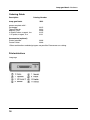
1
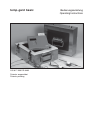
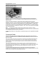
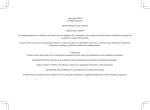
Measure what you see.
temp-gard basic
Betriebsanleitung
Operating Instructions
A member of
Additives & Instruments
temp-gard basic
255 017 989 DE 0406
Patente angemeldet
Patents pending
Bedienungsanleitung
Operating Instructions
BYK-Gardner GmbH
Lausitzer Str. 8
D-82538 Geretsried
Germany
Tel.
0-800-gardner
(0-800-4273637)
+49-8171-3493-0
Fax
+49-8171-3493-140
www.byk.com/instruments
BYK - Gardner USA
9104 Guilford Road
Columbia, MD 21046
USA
Phone 800-343-7721
301-483-6500
Fax
800-394-8215
301-483-6555
temp-gard basic Hardware
Sicherheitshinweise ........................................................................... 3
temp-gard basic System .................................................................... 5
Systemüberblick
Spezifikationen des temp-gard basic Systems mit Drucker (Canon)
Datenspeicherung
Standard-Hitzeschutzhülle
Langzeit- Hitzeschutzhülle
Messzeit
Hitzeschutzhülle
Thermoelemente
Thermoelement-Spezifikationen
Thermoelement-Kabel
Thermoelemente für den Ofenbetrieb
Wartung und Pflege
Hitzeschutzhülle und Kühlkörper
temp-gard basic Datenlogger
Thermoelement-Messfühler
Mineralisolierte Thermoelemente
Handhabung des temp-gard basic Systems
Messfühlerposition
Eine Messung starten
Die Ofenmessung
Die Messung beenden
Abkühlen der Schutzeinrichtung
Protokoll drucken
SRAM Karte neu formatieren
Kontrast im Display ändern
Quickstart
Quickstop
Parameter ändern
5
6
6
7
7
8
9
9
10
10
11
12
12
13
13
13
13
14
14
14
15
15
15
15
16
16
16
16
Software BYKWARE easy-link ........................................................ 17
Installation
Messung mit easy-link vorbereiten
Messdaten auslesen
17
17
17
Lieferhinweise................................................................................... 18
Druckerinterface ............................................................................... 18
Sprachenwahl
18
1
temp-gard basic Hardware
2
temp-gard basic Hardware
Sicherheitshinweise
!
Achtung temp-gard basic Datenlogger
Das Gerät darf nur für Temperaturmessungen an Objekten benutzt werden, die keine
spannungsführenden Teile besitzen.
Achtung heisse Hitzeschutzhülle
Messfühler und Hitzeschutzhülle nach Verlassen der heissen Zone nur mit entsprechender Schutzbekleidung (Handschuhe) berühren.
!
Achtung (heisse) Kühlkörper
Wenn ein Kühlkörper beschädigt wurde kann Kühlflüssigkeit austreten. Diese Substanz ist
nicht toxisch. Lassen Sie die ausgetretene Flüssigkeit abkühlen. Die trockenen Rückstände können mit einem Tuch entfernt werden.
Sofortmassnahmen bei
Hautkontakt: betroffene Stellen mit Wasser und Seife reinigen, verschmutzte Kleidung
ablegen
Augenkontakt: lang anhaltend mit Wasser spülen
Verschlucken: bei Unwohlsein ärztliche Hilfe hinzuziehen
!
Achtung Überhitzung
Das temp-gard basic wird mit 2 Stück 1,5 Volt Mignon ALKALINE Batterien betrieben.
Werden die Batterien über einen längeren Zeitraum Temperaturen über 70 °C ausgesetzt,
können sie auslaufen. Die Überschreitung der Temperatur können Sie auf einem
Thermostrip neben dem Batteriefach ablesen. Die Temperaturüberschreitung und ihre
Folgen können zu einer Zerstörung des Gerätes führen. Ein überhitztes Gerät muss vom
technischen Kundendienst auf seine Funktionsfähigkeit überprüft werden.
3
temp-gard basic Hardware
!
Achtung Batterien
Ausgetretene Batterieflüssigkeit (Kalilauge) greift die Schleimhäute an. Nicht in Augen,
Mund und Nase bringen. Die Flüssigkeit kann mit einem Tuch abgewischt werden. Bei
Hautkontakt mit Wasser abspülen.
!
Achtung Messfühler
PTFE ist nicht brennbar. Bei Temperaturen über 260 °C tritt eine thermische Zersetzung
des Produkts ein, wobei kleine Mengen an giftigen Gasen frei werden. Die wichtigsten
Spaltprodukte sind folgende:
Temperaturen höher als
Produkt
+400 °C
Siehe *1
+430 °C
Tetrafluorethylen
+440 °C
Hexafluorpropylen
+475 °C
Perfluorisobutylen
+500 °C
Carbonylfluorid (*1), das sich in feuchter Luft in das
Sauergas Fluorwasserstoff umwandelt
*1
Carbonylfluorid kann auch entstehen, wenn das PTFE-Band über einen längeren
Zeitraum einer Temperatur von 400 °C ausgesetzt ist.
Gesundheitsgefährdung:
Das Einatmen der Spaltprodukte von PTFE kann Polymerenfieber verursachen, eine
Krankheit mit denselben Symptomen wie Grippe.
Die Einnahme von bzw. der Hautkontakt mit PTFE verursachen keinerlei gesundheitliche
Schäden.
Es gibt keinerlei Gesundheitszustände, die sich durch den Kontakt mit PTFE im
allgemeinen verschlechtern.
Notfall- und Erste-Hilfe-Massnahmen:
Bei Unfällen mit PTFE-Gasen die betroffene Person aus dem Gefahrenbereich entfernen.
Bei der Gefahrenbekämpfung sind Sauerstoffgerät und Schutzkleidung zu tragen.
4
temp-gard basic Hardware
temp-gard basic System
Systemüberblick
Fest installierte Thermoelemente liefern nur einen punktuellen Hinweis zur Ofentemperatur und spiegeln nicht die Temperaturen des Produkts wieder. Mit dem temp-gard
basic System, das speziell für die Veredelungs- und Beschichtungsindustrie entwickelt
wurde, kann die schwierige und gleichzeitig notwendige Aufgabe, sowohl die Produkt- als
auch die Ofentemperatur bei Normalbetrieb aufzuzeigen, erfolgreich durchgeführt werden.
Die Systemhardware umfasst Thermoelemente (Messfühler), ein Datenerfassungsgerät
(Datenlogger) und eine Hitzeschutzhülle. Aus dieser Kombination ergibt sich ein selbstständig arbeitendes und unabhängiges Datenerfassungssystem, das den Prozess durchläuft und sowohl die Produkt- als auch die Umgebungstemperatur ohne Kabelgewirr
überwachen kann.
®
Die einfach zu bedienende Windows Software temp-chart (Option) stellt leistungsfähige,
hochentwickelte Analysewerkzeuge bereit, die sowohl zur Qualitätsprüfung als auch zur
Diagnose eingesetzt werden können. Im Falle der Qualitätsprüfung ermöglichen sie den
Vergleich von aktuellen Temperaturverläufen mit zuvor gespeicherten Bezugs- und
Toleranzkurven, um Abweichungen im Betrieb festzustellen. Im Falle der Diagnose
ermöglichen sie anhand neuartiger Analysemethoden das Erkennen von Problemen, die
Feinabstimmung des Prozesses und die Reduzierung der Betriebskosten.
Ein Druckerinterface (Option) ermöglicht den direkten Ausdruck einer
Grafik/Spitzenwerte auf einen Canon Drucker
Die folgenden Abschnitte beschreiben die für die Ofenprofilanwendungen geeignete
Hardware.
5
temp-gard basic Hardware
Spezifikationen des temp-gard basic Systems
(*1)
Kanäle
8
Thermoelement
Typ K
Temperaturbereich
-20° bis +500 °C (*1)
Messtakt
1 Sekunde bis 60 Minuten
Genauigkeit
± 0,5 °C
Auflösung
0,1 °C
Manueller Trigger
Ja
Zeit-Trigger
Ja (0 – 3000 min.)
Temperatur-Trigger
Ja (+30° bis +100 °C)
Batterie
2 x 1.5 V Alkaline (LR6 AA)
Lebensdauer der Batterie (Messzeit)
> 300 Stunden bei 5 Sek. Takt
Länge
138 mm
Tiefe
147 mm
Höhe
38 mm
Gewicht
0,7 kg
Die tatsächliche Höchsttemperatur ist durch die Temperaturkennzahlen der Hitzeschutzhülle begrenzt. Das temp-gard basic System mit der StandardHitzeschutzhülle darf nicht über +300 °C betrieben werden.
Datenspeicherung
Zeit
> 2 Jahre auf PCMCIA Karte
Speicher
512 kB auf der PCMCIA Karte
Beispiele:
6
Beispiele:
Messung mit 4 Fühlern
1 s Intervall
=
Messung mit 4 Fühlern
5 s Intervall
=
12,8 h
64 h
Messung mit 8 Fühlern
1 s Intervall
=
7,2 h
Messung mit 8 Fühlern
5 s Intervall
=
36 h
temp-gard basic Hardware
Standard-Hitzeschutzhülle
Kat. Nr. 3323 – Standardausführung für temp-gard basic
Masse
Temp. °C
Verweilzeit in
Minuten*
Höhe
Breite
Länge
Gewicht
Gewicht inkl.
temp-gard
101 mm
245 mm
209 mm
5,0 kg
5,7 kg
+100
+150
+200
+250
90
65
45
40
Langzeit- Hitzeschutzhülle
Kat. Nr. 3321 – Standardausführung für temp-gard
Masse
Temp. °C
Verweilzeit in
Stunden**
Höhe
Breite
Länge
Gewicht
Gewicht inkl.
temp-gard
165 mm
240 mm
255 mm
6,8 kg
7,5 kg
+100
+150
+200
+250
+300
9
6
4
3
1
*Diese Angaben gelten nur bei komplett abgekühlter Standard-Hitzeschutzhülle.
** Diese Angaben gelten nur bei komplett abgekühlter Standard-Hitzeschutzhülle mit
abgekühlten Kühlelementen.
Beachten Sie, dass sich diese Angaben aufgrund ständiger Weiterentwicklung der
Produkte ohne vorherige Ankündigung ändern können.
7
temp-gard basic Hardware
Messzeit
Anzahl
Sensoren
Taktrate in Sekunden
1
2
5
10
8
427 min
853 min
2133 min
4267 min
7
480 min
960 min
2400 min
4800 min
6
549 min
1097 min
2743 min
5486 min
5
640 min
1280 min
3200 min
6400 min
4
768 min
1536 min
3840 min
7680 min
3
960 min
1920 min
4800 min
9600 min
2
1280 min
2560 min
6400 min
––
1
1920 min
3840 min
9600 min
––
Beachten Sie, dass sich diese Angaben aufgrund ständiger Weiterentwicklung der
Produkte ohne vorherige Ankündigung ändern können.
8
temp-gard basic Hardware
Hitzeschutzhülle
Die Hitzeschutzhülle besteht aus Edelstahl und schützt den Datenlogger sowohl vor den
Temperaturen als auch den mechanischen Einflüssen, denen er in einem Industrieofen
ausgesetzt ist.
Der Hitzeschutz wird in erster Linie durch eine Keramikisolierung gewährleistet, die mit
einem Keramikfasertuch umgeben ist. Kühlkörper (nur in Langzeithitzeschutzhüllen)
gewährleisten einen zusätzlichen Schutz, wenn das System längere Zeit hohen
Temperaturen ausgesetzt ist. Der Kühlkörper ist mit einem ungiftigen und nicht
entflammbaren Material gefüllt, das seinen Aggregatzustand ändern kann. Es absorbiert
die Wärme und hält die Temperatur auf ca. +50 °C, bis es vollständig vom festen in den
flüssigen Zustand übergegangen ist.
Hinweis: Das Keramikisoliermaterial absorbiert Feuchtigkeit, wenn es in einer feuchten
Umgebung aufbewahrt wird. Dies hat zwar keine zerstörenden Auswirkungen auf die
Hitzeschutzhülle, jedoch wird die Leistungsfähigkeit beeinträchtigt, solange die Feuchtigkeit nicht entfernt wird.
Eine Stahlplatte am Deckel der Hitzeschutzhülle bietet eine gute Anbringungsmöglichkeit
für magnetische Messfühler.
Thermoelemente
Thermoelemente nutzen den im 19. Jahrhundert von Seebeck entdeckten thermoelektrischen Effekt. Danach baut sich beim Kontakt zweier unterschiedlicher Metalle eine
Spannung auf, die sich proportional mit der Temperatur an der Kontaktstelle ändert.
Die tatsächlich gemessene Spannung ist proportional zu der Temperaturdifferenz, die
zwischen der „warmen“ und der „kalten“ Verbindungsstelle des Thermoelements besteht.
(Die „warme“ Verbindungsstelle ist die Messstelle und wird mit dem zu messenden Objekt
in Wärmekontakt gebracht, die „kalte“ Verbindungsstelle wird konstant auf einer Referenztemperatur gehalten.)
Der Einsatz von Thermoelementen erfordert eine hochentwickelte Elektronik, damit Fehler
bei der Messung der Spannung vermieden werden. Mögliche Fehler beinhalten eine
geringe Linearität über den Messbereich und Ungenauigkeiten aufgrund von Temperaturschwankungen an der kalten Verbindungsstelle.
9
temp-gard basic Hardware
Um diesen möglichen Fehlern Rechnung zu tragen, muss die Elektronik des Messsystems
an der kalten Verbindungsstelle eine Temperatur von null Grad simulieren und gleichzeitig
jegliche Nichtlinearität über den Temperaturbereich des Thermoelements ausgleichen.
Thermoelement-Spezifikationen
Im Laufe der Jahre wurden „Standard-Thermoelemente“ auf der Basis von Materialien
entwickelt, die aufgrund ihrer Empfindlichkeit (Spannungsänderung bei Temperaturänderung), ihrer Linearität, (konstante Empfindlichkeit über den auftretenden Temperaturbereich), ihres Preises und ihrer Verfügbarkeit ausgewählt wurden. Die derzeit als
Standard verwendeten Thermoelemente umfassen die Typen K, N, R, S und T, wobei
jeder Typ durch die Farbe des Steckers gekennzeichnet wird. Die „Standard-Thermoelemente“ für den Ofenbetrieb sind Thermoelemente vom Typ K.
Typ
K
Temperaturbereich
Kabelisolierung
Genauigkeit der von BYK-Gardner
gelieferten Messfühler
-150 bis +1370 °C
Glasfaser, Mineral
oder PTFE
(0 bis +500 °C) ± 1,1 °C oder ±0,4%,
je nachdem, welcher Wert grösser ist
Thermoelement-Kabel
Die Betriebstemperatur der Thermoelemente ist durch die Temperaturkenngrössen des für
die Kabel verwendeten Isoliermaterials begrenzt.
Isolierung
Obere Temperaturgrenze
Glasfaser, dick
+500 °C bei Dauerbetrieb,
+700 °C bei kurzzeitigem Betrieb
Mineral
+1250 °C
PTFE
+260 °C
Messfühlerkabel mit Glasfaserisolierung sind mit einem Silikonharz-Bindemittel imprägniert und eignen sich für den Dauerbetrieb bei Temperaturen bis +500 °C und den kurzzeitigen Betrieb bei Temperaturen bis +700 °C.
Messfühlerkabel mit PTFE-Isolierung (PTFE=Polytetrafluorethylen) eignen sich für
allgemeine Anwendungen bei Temperaturen bis +260 °C. PTFE ist ein
widerstandsfähiges, biegsames und nicht haftendes Material. Dies ist die
Standardkabelisolierung der temp-gard basic Messfühler. PTFE-isolierte Messfühlerkabel
können nicht verwendet werden, wenn es sein kann, dass sich die Kabel in unmittelbarer
Nähe der Heizelemente befinden.
!
Achtung
PTFE ist nicht brennbar. Bei Temperaturen über +260 °C tritt eine thermische Zersetzung
des Produkts ein, wobei kleine Mengen an giftigen Gasen frei werden. Die wichtigsten
Spaltprodukte sind folgende:
10
temp-gard basic Hardware
Temperaturen höher als
Produkt
+400 °C
Siehe *1
+430 °C
Tetrafluorethylen
+440 °C
Hexafluorpropylen
+475 °C
Perfluorisobutylen
+500 °C
Carbonylfluorid (*1), das sich in feuchter Luft in das
Sauergas Fluorwasserstoff umwandelt
*1
Carbonylfluorid kann auch entstehen, wenn das PTFE-Band über längeren Zeitraum
einer Temperatur von +400 °C ausgesetzt ist.
Gesundheitsgefährdung:
Das Einatmen der Spaltprodukte von PTFE kann Polymerenfieber verursachen, eine
Krankheit mit denselben Symptomen wie Grippe.
Die Einnahme von bzw. der Hautkontakt mit PTFE verursachen keinerlei gesundheitliche
Schäden.
Es gibt keinerlei Gesundheitszustände, die sich durch den Kontakt mit PTFE im
allgemeinen verschlechtern.
Notfall- und Erste-Hilfe-Massnahmen:
Bei Unfällen mit PTFE-Gasen die betroffene Person aus dem Gefahrenbereich entfernen.
Bei der Gefahrenbekämpfung sind Sauerstoffgerät und Schutzkleidung zu tragen.
Thermoelemente für den Ofenbetrieb
Thermoelemente vom Typ K weisen eine warme Verbindungsstelle auf, die eine NickelChrom-Legierung und Nickel-Aluminium-Legierung miteinander verbindet. Dies sind die
Standardmessfühler für den Ofenbetrieb. Sie sind mit einer Vielzahl an Befestigungsmöglichkeiten erhältlich, als magnetische, klemmbare, haftende und anschraubbare Messfühler. In internationalen Spezifikationen für Messfühler vom Typ K sind die Empfindlichkeit und Linearität über einen Temperaturbereich von 0 bis +1250 °C spezifiziert. Der
tatsächliche Betriebsbereich ist durch die Eigenschaften der Kabelisolierung und durch die
Eigenschaften des Kabelmantels begrenzt.
Klemmbare Messfühler zur Messung
der Oberflächentemperatur
von 0 bis +260 °C
Folien-Messfühler zur Messung
der Oberflächentemperatur
von 0 bis +260 °C
Magnetischer Messfühler zur Messung
der Oberflächentemperatur
von 0 bis +260 °C
Magnetischer Messfühler
zur Messung der Lufttemperatur
von 0 bis +260 °C
Messfühler mit offenenem Anschluss
Anschraubbarer Messfühler
zur Messung der Objekttemperatur zur Messung der Oberflächentemperatur
von 0 bis +260 °C
von 0 bis +500 °C
11
temp-gard basic Hardware
Wartung und Pflege
Hitzeschutzhülle und Kühlkörper
Hinweise zum Abkühlen
Bitte beachten Sie die Sicherheitshinweise auf Seite 3 und die Hinweise zum Abkühlen
der Schutzeinrichtung auf Seite 15
Prüfung Standard-Hitzeschutzhülle basic (ohne Kühlkörper)
Überprüfen Sie die abgekühlte Hitzeschutzhülle auf Schäden, bevor Sie sie in einer
trockenen Umgebung lagern, um ein Feuchtwerden der Keramikisolierung zu verhindern.
Überprüfen Sie die Dichtungen und Schliessvorrichtungen der Hitzeschutzhülle. Beheben
Sie alle Schäden, bevor Sie die Hitzeschutzhülle erneut einsetzen.
Prüfung Langzeit-Hitzeschutzhülle
Die Kühlkörper sollten immer aus der Hitzeschutzhülle entfernt werden. Schütteln Sie die
Kühlkörper nach dem Herausnehmen um zu prüfen, ob das Kühlmittel flüssig geworden
ist. Wenn sich das Kühlmittel verflüssigt hat, müssen die Kühlkörper über 8 Stunden bei
einer Temperatur kleiner als +10 °C abgekühlt werden. Wenn das Kühlmittel fest geblieben ist, reicht es aus, die Kühlkörper über 8 Stunden bei einer Temperatur kleiner als
+20 °C abzukühlen.
Mechanisch beschädigte Kühlkörper auf Dichtigkeit prüfen.
Wenden Sie sich an BYK-Gardner, wenn das Kühlmittel aus dem Kühlkörper ausläuft. Es
handelt sich um eine unschädliche und ungiftige Substanz, die im festen Zustand eine
harte pulverförmige Konsistenz aufweist und einen leichten Säuregeruch hat. Wenn das
Kühlmittel auf den Boden der Hitzeschutzhülle ausgelaufen ist, entfernen Sie es erst,
wenn es fest ist. Bitte beachten Sie die Sicherheitshinweise auf Seite 1.
Überprüfen Sie die abgekühlte Hitzeschutzhülle und Kühlkörper auf Schäden, bevor Sie
sie in einer trockenen Umgebung lagern, um ein Feuchtwerden der Keramikisolierung zu
verhindern.
Überprüfen Sie die Dichtungen und Schliessvorrichtungen der Hitzeschutzhülle. Beheben
Sie alle Schäden, bevor Sie die Hitzeschutzhülle erneut einsetzen.
12
temp-gard basic Hardware
temp-gard basic Datenlogger
Lagern Sie den Datenlogger in einer staubfreien Umgebung. Entfernen Sie die Batterien,
wenn er länger als drei Wochen gelagert wird.
Senden Sie den Datenlogger jährlich zu Kalibrierungszwecken an BYK-Gardner.
Thermoelement-Messfühler
Allgemeine Hinweise
Das Anheben bzw. Entfernen der Messfühler an den Kabeln führt zu Schäden an den
Kabeln und Anschlüssen.
Untersuchen Sie die Kabel, und ersetzen Sie jene Messfühler, die eine beschädigte
Isolierung aufweisen.
Mineralisolierte Thermoelemente
Das mineralisolierte Messfühlerkabel nutzt sich durch den Temperaturwechsel, dem es
ausgesetzt ist, ab und kann unter Umständen brüchig werden. Stellen Sie sicher, dass der
minimale Biegeradius grösser als 25 mm ist.
Handhabung des temp-gard basic Systems
Bitte beachten Sie die Sicherheitshinweise auf Seite 3.
!
Achtung
Bei Umgebungstemperaturen über +40 °C darf das temp-gard basic nur in einer
Hitzeschutzhülle betrieben werden. Die Verweilzeit bei +250 °C Umgebungstemperatur
beträgt maximal 40 Minuten. Mit der Standard-Hitzeschutzhülle darf das temp-gard basic
System nicht über +300 °C verwendet werden.
13
temp-gard basic Hardware
Messfühlerposition
Die Bauart und Anordnung der Messfühler beeinflussen die Produkttemperatur. Das zu
vermessende Produkt oder Objekt bestimmt die Bauart und Grösse (Masse) der Messfühler. Je nach Materialstärke und magnetischen Eigenschaften des Objekts werden
Magnetfühler, Klammerfühler oder Klebefühler eingesetzt. Die Messfühler werden immer
von Steckplatz 1 bis x an das temp-gard basic Gerät angeschlossen.
Eine Messung starten
•
•
•
•
•
•
Schliessen sie die Messfühler an das temp-gard basic Gerät an.
Führen Sie eine SRAM Karte mit der Standardvorlage in das Laufwerk ein.
Schalten Sie das temp-gard basic Gerät mit der start/stop Taste ein. Im Display
werden die auf der Karte gespeicherten Einstellungen der Vorlage angezeigt.
Mit der mode Taste können die Anzahl der Fühler, die Messzeit und der Messtakt
direkt am temp-gard basic geändert werden.
Starten Sie die Messung durch Betätigen der start/stop Taste.
Legen Sie das temp-gard basic in die Hitzeschutzhülle ein.
!
Achtung
Überprüfen Sie zunächst, ob die Hitzeschutzhülle nach dem letzten Durchlauf genügend
abgekühlt ist.
•
•
•
•
Schrauben Sie die Kühlkörper (Option) in die beiden Hälften der Hitzeschutzhülle ein.
Stellen Sie das temp-gard basic in die untere Hälfte der Hitzeschutzhülle.
Stellen Sie sicher, dass die Dichtungen sauber und unbeschädigt sind.
Legen Sie die Thermoelementkabel in der seitlichen Aussparung der Hitzeschutzhülle
nebeneinander und verschliessen Sie den Behälter mit der oberen Hälfte.
Die Ofenmessung
•
Bringen Sie die Messfühler am Objekt an.
!
Achtung
Sichern Sie alle Thermoelementkabel so, dass sie sich innerhalb des Ofens nicht
verhaken können.
•
14
Hängen Sie die Hitzeschutzhülle an das Transportband und überprüfen Sie den
Freiraum für die Messfühler, die Kabel und die Hitzeschutzhülle.
temp-gard basic Hardware
Die Messung beenden
!
Achtung
Alle Komponenten können nach der Messung sehr heiss sein.
Bitte beachten Sie die Sicherheitshinweise auf Seite 3
•
•
Nehmen Sie die heisse Schutzhülle mit entsprechender Schutzkleidung (Handschuhe)
vom Transportband, öffnen Sie die Hitzeschutzhülle und betätigen Sie die start/stop
Taste am Datenlogger.
Entnehmen Sie die SRAM Karte.
Abkühlen der Schutzeinrichtung
•
•
•
•
Stellen Sie die heisse Hitzeschutzhülle auf hitzebeständige Abstandshalter, auf eine
Keramikfaserdecke oder auf feuerfestes Material, um ein gleichmässiges Abkühlen zu
ermöglichen. Wird eine heisse Hitzeschutzhülle direkt auf eine kalte Oberfläche
gestellt, kann es aufgrund der unterschiedlichen Abkühlungszeiten zu Deformationen
des Gehäuses kommen.
Den Deckel nur von der abgestellten Hitzeschutzhülle entfernen.
Die von der Hitzeschutzhülle absorbierte Wärme wird weiterhin die Temperatur des
Kühlkörpers (Option) und des Datenloggers beeinflussen. Entfernen Sie daher beide
Komponenten aus der Hitzeschutzhülle, sobald die Prüfung beendet ist. Lassen Sie
sie vor dem erneuten Einsatz abkühlen. In den meisten Fällen ist ein Abkühlen über
Nacht ausreichend.
Bitte beachten Sie die Sicherheitshinweise auf Seite 3.
Protokoll drucken (Option)
•
•
•
•
•
•
•
•
Schließen Sie das Interface an einen Canon-Drucker an.
Schließen Sie das Netzkabel des Druckers an.
Schalten Sie den Drucker mit der Taste POWER ein
Der Drucker wird für den Normalbetrieb initialisiert. Warten Sie in jedem Fall das
Ende der Initialisierung ab, bevor Sie eine Kurve ausdrucken.
Führen Sie eine SRAM Karte mit der Messung in das Laufwerk des DruckerInterfaces ein.
Der Drucker startet automatisch und Druckt Grafik und Messwerte auf einer A4 Seite
entsprechend der eingestellten Sprache.
Durch entfernen und neu einführen der SRAM Karte startet der Drucker neu.
Die SRAM Karte kann danach für eine neue Messung benutzt werden.
SRAM Karte neu formatieren
•
•
•
•
•
Führen Sie die SRAM Karte in das Laufwerk des temp-gard basic Gerätes ein.
Schalten Sie das temp-gard basic Gerät durch die Taste start/stop ein.
Durch gleichzeitiges drücken der mode und operate Taste wird das
Formatierungsprogramm aufgerufen
Sie werden aufgefordert mit der operate Taste das Formatieren zu bestätigen.
Nach wenigen Minuten ist der Vorgang beendet, und eine Messung mit den
Standardvorgaben kann durchgeführt werden.
15
temp-gard basic Hardware
Kontrast im Display ändern
•
•
•
•
Führen Sie die SRAM Karte in das Laufwerk des temp-gard basic Gerätes ein.
Schalten Sie das temp-gard basic Gerät mit der start/stop Taste ein.
Drücken Sie gleichzeitig start/stop und mode Taste.
Sie werden aufgefordert mit der operate oder mode Taste die Kontrasteinstellung zu
verändern.
Quickstart
•
•
•
Führen Sie die SRAM Karte in das Laufwerk des temp-gard basic Gerätes ein.
Halten Sie die start/stop Taste 5 Sekunden lang gedrückt.
Die Messung beginnt ohne das im Display alle Funktionen angezeigt werden
Quickstop
•
•
Halten Sie die start/stop Taste 5 Sekunden lang gedrückt.
Die Messung wird ohne Abfrage beendet.
Parameter ändern
•
•
Führen Sie die SRAM Karte in das Laufwerk des temp-gard basic Gerätes ein
Schalten Sie das temp-gard basic Gerät mit der start/stop Taste ein. Im Display
werden die auf der Karte gespeicherten Einstellungen der Vorlage angezeigt.
•
Mit der mode Taste können folgende Parameter ändern:
Anzahl der Messfühler
Temperaturbereich
Messdauer
Messtakt
Triggerarten
Triggerdaten
Uhrzeit
Datum
16
von 1 bis 8
120°C, 280°C, 500°C
von 1 bis 3000 Minuten (50 Stunden)
von 1 Sekunde bis 99 Minuten
manuel, Temperatur, Zeit
30°C bis 99°C oder 1 bis 3000 Minuten
Stunden und Minuten
Tag, Monat, Jahr
temp-gard basic Hardware
Software BYKWARE easy-link
Installation
Systemvorraussetzung siehe Rückseite CD-Verpackung
•
•
•
•
•
•
•
•
•
CD easy-link in das CD-Laufwerk legen
Windows Explorer öffnen
CD-Laufwerk mit der CD BYK-Gardner auswählen
Setup starten
Sie werden durch das Installationsprogramm geführt.
Nach der Fertigstellung CD entfernen
Excel Datei TempGardLink (BYKWARE, temp-gard link) suchen und öffnen
File mit der Taste Makros aktivieren öffnen.
In Configure ComPort, Sprache und Temperatur einstellen.
Messung mit easy-link vorbereiten
!
Achtung
Die SRAM-Karte bleibt als Speichermedium immer im temp-gard basic!
•
•
•
•
•
Verbindungskabel (9 Pin) am PC und temp-gard basic anschließen.
Menü Karte ändern wählen
Temp-Bereich, Messtakt, Trigger, Anzahl der Messfühler und
Messdauer wählen.
Verbindungskabel lösen und Messung wie unter Handhabung temp-gard basic
System beschrieben, durchführen
Messdaten auslesen
•
•
•
•
temp-gard basic nach der Messung wieder mit Ihrem PC verbinden.
In der Software TempGardLink die Taste Lade Daten betätigen
Die Messwerte werden in die Spalten von A bis XX eingelesen.
Messdaten mit dem Befehl Speicher unter in Datei mit einen neuen Namen
speichern.
Jetzt können Sie alle Funktionen von Excel für Ihre Analyse benutzen!
17
temp-gard basic Hardware
Lieferhinweise
Lieferumfang
Bestell-Nummer
temp-gard basic
3333
bestehend aus*:
Datenlogger
Hitzeschutzhülle
Memory-Card
3 Objekt-Fühler, Magnet, 3 m
1 Luft-Fühler, Magnet, 3 m
3315
3323
3330
3125
3131
Zubehör (Option)
Druckerinterface
Canon Drucker
3336
3340
* Andere Kombinationen und Ausführungen sind möglich, siehe Katalog.
Druckerinterface
Sprachenwahl
18
temp-gard basic Hardware
Safety Information .............................................................................. 3
temp-gard basic System .................................................................... 5
System Overview
Specifications of the temp-gard basic System with printer (canon)
5
6
Data Storage
Standard Barriers
Long-time Barriers
Measurement Time
6
7
7
8
Barriers and Heat Sinks
Thermocouple Probes
9
9
Thermocouple Specifications
Cable Insulation
Thermocouple Insulation
Temperatures greater than
Thermocouple Probes for Oven Operation
Care and Maintenance
10
10
10
11
11
12
Thermal Barriers and Heat Sinks
temp-gard basic Data Logger
Thermocouple Probes
Mineral Insulated Thermocouple Probes
12
13
13
13
Operating the temp-gard basic System
13
Position of Thermocouple Probes
Starting a Measurement
Recording the Oven Temperature
Finishing the Measurement
Cooling Down the Protective Parts
How to print a protocol
Reformatting the SRAM-card
Changing the Contrast in the Display
Quickstart
Quickstop
Changing Parameters
13
14
14
14
15
15
15
15
16
16
16
The easy-link BYKWARE Software ................................................. 17
Installation
Preparing a measurement with easy link
Reading the Data Values
17
17
17
Ordering Guide ................................................................................. 18
Printerinterface ................................................................................. 18
1
temp-gard basic Hardware
2
temp-gard basic Hardware
Safety Information
!
Attention temp-gard basic data logger
The instrument must not be used to measure the temperature of objects that have live
parts.
Attention Hot Thermal Barrier
Never touch the hot thermocouple probes or the thermal barrier without appropriate
protective clothing (protective gloves) after leaving the hot area.
!
Attention (Hot) Heat Sinks
If a heat sink is damaged, the cooling agent might leak out. This liquid is non-toxic. Wait
until the liquid has cooled down. The dry residues can be wiped off with a cloth.
Immediate action in the event of
Skin contact: clean affected areas with soap and water, remove contaminated clothing
Eye contact:
rinse with water for a prolonged time
Swallowing:
seek medical advice if unwell
!
Attention Overheating
The temp-gard basic is powered by two 1.5 Volts Mignon ALKALINE batteries. If these
batteries are subjected to temperatures above +70 °C over a long period of time they
might leak. A thermometer strip next to the battery case indicates exceeding temperatures.
Overheating might destroy the instrument. An overheated instrument always has to be
checked by technical service staff.
!
Attention Batteries
Leaking battery liquid (potash lye) attacks the mucous membranes. Avoid any contact with
eyes, mouth or nose. The liquid can be wiped off with a cloth. In case of skin contact, rinse
with water.
3
temp-gard basic Hardware
!
Attention Thermocouple Probes
PTFE is non-flammable. Temperatures greater than +260 °C will cause a thermal
decomposition of the product and release small amounts of toxic fumes. The most
important decomposition products are:
Temperatures greater than
Product
+400 °C
See note *1
*1
+430 °C
Tetrafluorethylene
+440 °C
Hexafluorpropylene
+475 °C
Perfluorisobutylene
+500 °C
Carbonyl fluoride (*1), which, in moist air, converts to the
acid gas hydrogen fluoride
Carbonyl fluoride may also be produced if the PTFE tape is kept at +400 °C (752 °F)
for an extended period of time.
Health Hazards:
The inhalation of PTFE decomposition products form PTFE can produce ‘Polymer Fume
Fever’ with the same symptoms as influenza.
There is no risk from ingestion or skin contact.
There are no medical conditions generally aggravated by exposure to PTFE.
Emergency and First Aid Procedures:
In case of a PTFE fume accident, the affected person has to be rescued from the danger
area immediately. Self-contained breathing apparatus and protective clothing are
indispensable when fire-fighting.
4
temp-gard basic Hardware
temp-gard basic System
System Overview
Permanently installed fixed point thermocouples provide a very localized indication of oven
operation, but do not reflect temperatures as experienced by the product. Designed
specifically for use in the general coating and finishing industry the temp-gard basic
system provides an effective solution to the difficult, but essential task of profiling both
product and oven temperatures during normal operation.
The system hardware comprises Thermocouple Temperature Transducers (Probes), a
Data Logger and a Thermal Barrier. The combination resulting in a self-contained data
acquisition system, which travels through the process monitoring product and ambient
temperature, without trailing cables.
®
The easy to use Windows based temp-chart (optional) software provides powerful,
sophisticated analytical tools operating as both a quality inspection tool, and an
investigative diagnostic tool. In the inspection role, it allows comparison of current
temperature characteristics with previously stored reference and target curves to detect
operating abnormalities. In the diagnostic role, its innovative analysis techniques help to
identify problems, fine tune the process and reduce running costs.
A printer interface (optional) permits direct output of charts/peak values to a Canon
printer.
The following sections describe hardware suitable for oven profiling applications.
5
temp-gard basic Hardware
Specifications of the temp-gard basic System with printer (canon)
(*1)
Channels
8
Thermocouple
Type K
Temperature Range
-20° to +500 °C (*1)
Sampling Interval
1 second to 60 minutes
Accuracy
± 0,5 °C
Resolution
0,1 °C
Manual Trigger
Yes
Time Trigger
Yes (0 – 3000 min.)
Temperature Trigger
Yes (+30° to +100 °C)
Battery
2 x 1.5 V Alkaline (LR6 AA)
Battery Life (Measuring Time)
> 200 hours at 5 sec interval
Length
138 mm
Width
147 mm
Height
38 mm
Weight
0,7 kg
The practical maximum temperature is limited by the temperature capabilities of the
thermal barrier. If the temp-gard basic system is used with the standard thermal
barrier, a maximum temperature of +300 °C must not be exceeded.
Data Storage
Time
> 2 years on PCMCIA card
Storage
512 kB on PCMCIA card
Examples:
6
Examples:
measurement with 4 sensors
1 s interval
=
12.8 h
measurement with 4 sensors
5 s interval
=
64 h
measurement with 8 sensors
1 s interval
=
7.2 h
measurement with 8 sensors
5 s interval
=
36 h
temp-gard basic Hardware
Standard Barriers
Cat. No. 3323 – Standard
Height
Width
Length
Weight
Weight incl..
temp-gard
101 mm
245 mm
209 mm
5,0 kg
5,7 kg
Temp. °C
+100
+150
+200
+250
Duration in
minutes*
90
65
45
40
Dimensions
Long-time Barriers
Cat. No. 3321 – Long-time barriers
Dimensions
Temp. °C
hours**
Height
Width
Length
Weight
Weight
incl.Duration in .
temp-gard
165 mm
240 mm
255 mm
6,8 kg
7,5 kg
+100
+150
+200
+250
+300
9
6
4
3
1
*These values are only valid for a completely cooled down heat barrier.
** These values are only valid for a completely cooled down heat barrier with cooled down
heat sinks.
Please note, due to continuing product development, specifications are subject to change
without prior notice.
7
temp-gard basic Hardware
Measurement Time
Number of
Sensors
Sampling Interval in Seconds
1
2
5
10
8
427 min
853 min
2133 min
4267 min
7
480 min
960 min
2400 min
4800 min
6
549 min
1097 min
2743 min
5486 min
5
640 min
1280 min
3200 min
6400 min
4
768 min
1536 min
3840 min
7680 min
3
960 min
1920 min
4800 min
9600 min
2
1280 min
2560 min
6400 min
––
1
1920 min
3840 min
9600 min
––
Please note: Due to continuing product development specifications are subject to change
without prior notice.
8
temp-gard basic Hardware
Barriers and Heat Sinks
Made from stainless steel the Thermal Barrier provides the thermal and mechanical
protection necessary for the data logger to travel through the hostile environment of an
industrial oven.
Ceramic insulation covered by a ceramic fiber cloth provides the primary thermal
protection. Heat sinks ( only in long-time barriers) provide additional, secondary protection
allowing the system to operate at high temperature for extended periods. The heat sinks
are filled with a non-toxic, non-flammable phase changing material. This material absorbs
the heat and maintains a temperature of approx. +50 °C until all the material has changed
from solid to liquid state.
Note:
The ceramic insulation material will absorb moisture if stored in a damp
environment. Although this will not result in damage to the thermal barrier, its performance
will be degraded until the moisture is removed.
A steel pad on the barrier’s lid provides a convenient stage area for magnetically attached
probes.
Thermocouple Probes
th
Thermocouple probes utilize the Seebeck effect which, discovered in the 19 century,
results in a voltage proportional to temperature being produced at the junction of any two
dissimilar metals.
The actual voltage measured is proportional to the temperature difference between the
thermocouples “Hot” and “Cold” junctions, the “Hot” junction being the measurement
junction, and the “Cold” junction being the junction of thermocouple and measurement
instrumentation.
The practical implementation of thermocouples requires sophisticated electronics to
eliminate potential measurement errors. These potential errors include poor linearity over
the measurement range, and inaccuracy due to temperature variations at the Cold
reference junction.
To accommodate these the electronics in the measuring system must simulate a
temperature of zero degrees at this second junction, as well as compensating for any non
linearity over the range of the thermocouple operation.
9
temp-gard basic Hardware
Thermocouple Specifications
Over the years, ‘standard’ thermocouples have been developed using materials chosen for
sensitivity (voltage change per temperature change), linearity, (consistency of sensitivity
over the useful temperature range), price and availability. Current standards include types
K, N, R, S and T, each type being identified by the color of the connector. The ‘standard’
thermocouple probe for oven operation is the type K.
Type
Temperature
Range
K
-150 to +1370 °C
Cable Insulation
Glass Fiber, MI or
PTFE
Accuracy of probes supplied by
BYK-Gardner
(0 to +500 °C) ± 1,1 °C or ±0,4%,
whichever is greater
Thermocouple Insulation
The practical operating temperature of the thermocouple probes is limited by the
temperature characteristics of the cable insulation material.
Insulation
Upper Temperature Limit
Glass Fiber, thick
+500 °C (932 °F) continuous,
+700 °C (1292 °F) peak
Mineral Insulation (MI)
+1250 °C
PTFE
+260 °C
Glass Fiber insulated probes are impregnated with a silicone resin binder and suitable for
continuous operation at temperatures up to +500 °C (932 °F), and short term operation at
temperatures up to +700 °C (1292 °F).
PTFE (PTFE=Polytetrafluorethylene) is a robust, flexible, non-stick material suitable for
general purpose use at temperatures up to +260 °C (500 °F). It is the standard insulation
for temp-gard basic probes. It cannot be used when probe cables may be in close
proximity to heating elements.
!
Attention
PTFE is non-flammable. Temperatures greater than +260 °C will cause a thermal
decomposition of the product and release small amounts of toxic fumes. The most
important decomposition products are:
10
temp-gard basic Hardware
Temperatures greater than
Product
+400 °C
*1
See note *1
+430 °C
Tetrafluorethylene
+440 °C
Hexafluorpropylene
+475 °C
Perfluorisobutylene
+500 °C
Carbonyl fluoride (*!), which, in moist air, converts to the
acid gas hydrogen fluoride
Carbonyl fluoride may also be produced if the PTFE tape is kept at +400 °C (752 °F)
for an extended period of time.
Health Hazards:
The inhalation of PTFE decomposition products form PTFE can produce ‘Polymer Fume
Fever’ with the same symptoms as influenza.
There is no risk from ingestion or skin contact.
There are no medical conditions generally aggravated by exposure to PTFE.
Emergency and First Aid Procedures:
In case of a PTFE fume accident, the affected person has to be rescued from the danger
area immediately. Self-contained breathing apparatus and protective clothing are
indispensable when fire-fighting.
Thermocouple Probes for Oven Operation
Type K thermocouple probes having a hot junction combining Nickel Chromium Alloy and
Nickel Aluminum Alloy are the standard probes for oven operation. They are available with
a variety of mounting configurations including magnetic, clip on, adhesive and washer.
International specifications for type K define a sensitivity and linearity over the range 0 °C
to +1250 °C (32 °F to 2282 °F). Their practical operating range is limited by the properties
of the cable insulation and sheathing.
Clip-on
surface temperature probe
from 0 to +260 °C
Magnetic
surface temperature probe
from 0 to +260 °C
Magnetic
air temperature probe
from 0 to +260 °C
Surface temperature
foil-probe
from 0 to +260 °C
Open Junction
object temperature probe
from 0 to +260 °C
Bolt-on
surface temperature probe
from 0 to +500 °C
11
temp-gard basic Hardware
Care and Maintenance
Thermal Barriers and Heat Sinks
Cooling
Please observe the safety information on page 3 and the information on cooling down the
protective parts on page 15.
Examination Standard Barrier basic (without heat sinks)
Examine the cooled-down thermal barrier for damages before storing it in a dry
environment to prevent the ceramic insulation from absorbing water.
Check the thermal barrier’s seals and closing mechanism , rectify any damage before
further use.
Examination Long-time Barrier
Always take the heat sinks out of the thermal barrier. Shake the heat sinks to find out
whether the cooling agent has changed form solid to liquid state. If the cooling agent is still
in a solid state, the heat sinks need to cool down for 8 hours at a temperature lower than
+10 °C. If the cooling agent has remained solid, it is sufficient to cool down the heat sinks
for 8 hours at a temperature lower than +20 °C.
Make sure that mechanically damaged heat sinks don’t leak.
Contact BYK-Gardner if the heat sink phase change material leaks. It is a non-toxic waxlike substance that dries hard powdery white and has a slight acidic smell. Wait until it is
dry before scraping of any material that has leaked onto the surface of the barrier. Please
observe the safety information on page 3.
Examine the cooled thermal barrier and heat sinks for damage before storing in a dry
environment to avoid the ceramic insulation absorbing water.
Check the thermal barrier’s seals and closing mechanism, rectify any damage before
further use.
12
temp-gard basic Hardware
temp-gard basic Data Logger
Store in a dust free environment. Remove batteries when storing for more than two to
three weeks.
Return to BYK-Gardner annually for calibration.
Thermocouple Probes
General
Lifting or removing the probes by the cables will damage the cables and connectors.
Examine cables, and replace any probes found to have damaged insulation.
Mineral Insulated Thermocouple Probes
The thermal cycling the probes experience causes the MI cable to age, and eventually to
become brittle. Handle them with care ensuring the minimum bend radius is greater than
25 mm.
Operating the temp-gard basic System
Please observe the safety information on page 3.
!
Attention
If the ambient temperature is above +40 °C, the temp-gard basic Instrument must be
used in the thermal barrier. The maximum duration at an ambient temperature of +250 °C
is 40 minutes. If the temp-gard basic system is used with the standard heat barrier, a
maximum temperature of +300 °C must not be exceeded.
Position of Thermocouple Probes
Type and positon of the probes influence the product temperature. The product or object
to be measured determines the type and size (material mass) of the probes used.
Depending on the thickness and magnetic properties of the object, either magnetic probes,
clamps or adhesive probes are used. The thermocouple probes are always plugged into
the temp-gard basic instrument from jack 1 to x.
13
temp-gard basic Hardware
Starting a Measurement
•
•
•
•
•
•
Connect the thermocouple probes to the temp-gard basic instrument.
Insert an SRAM card with a standard template into the slot of the temp-gard basic
instrument.
Press the start/stop key to switch on the instrument. The template setup is displayed.
The preset number of probes, the duration and the sampling interval of the measurement can be adjusted by pressing the mode key of the temp-gard basic instrument.
Start the measurement by pressing the start/stop key.
Embed the temp-gard basic in the thermal barrier.
!
Attention
Make sure that the thermal barrier have cooled down completely after the previous
measurement.
•
•
•
•
Screw down the heat sinks (optional) in both halfs of the thermal barrier.
Place the temp-gard basic in the lower part of the thermal barrier.
Make sure that all gaskets are clean and without defects.
Place the thermocouple cables side by side in the lateral sparings of the thermal
barrier and lock the box with the upper part.
Recording the Oven Temperature
•
Attach the thermocouple probes to the object.
!
Attention
Secure all cables and make sure that they cannot get tangled up when travelling through
the oven.
•
Hang the thermal barrier on the belt and make sure there is enough free space for the
thermocouple probes, the cables and the thermal barrier.
Finishing the Measurement
!
Attention
All parts can be hot after the measurement.
Please observe the safety information on page 3.
14
temp-gard basic Hardware
•
•
Remove the hot thermal barrier from the belt wearing appropriate protective clothing
(protective gloves). Open the thermal barrier and press the start/stop key of the data
logger.
Take out the SRAM- card .
Cooling Down the Protective Parts
•
•
•
•
Place hot thermal barriers on heat-resistant spacers, a ceramic fiber blanket or
refractory material to ensure uniform cooling. Placing a hot thermal barrier directly
onto a cold surface may cause the housing to deform due to the different cooling rates
of the surfaces.
Do not remove the cover before the thermal barrier is in place
Since the heat absorbed by the thermal barrier continues to affect the temperature of
the heat sink (optional) and data logger, remove these parts from the thermal barrier
as soon as the test is completed. Allow them to cool down before further use. In most
cases cooling overnight is sufficient.
Please observe the safety information on page 3.
How to print a protocol
•
•
•
•
•
•
•
•
Connect the inerface to a Canon printer.
Connect the power cord of the printer to the mains supply.
Switch on the printer by pressing the POWER key.
The printer will initialise for normal operation. Do not starting before the initialising
process is completed.
Put the SRAM-card containing the measurement data into the drive of the printer
interface.
The printer will automatically start printing the chart and data values on a size A4
sheet in the language selected,
By removing and re-inserting the SRAM-card, the printer will start printing again.
The SRAM-card can then be used for further meassurements.
Reformatting the SRAM-card
•
•
•
•
•
Introduce the SRAM-card into the drive of the temp-gard basic instrument
Switch on temp-gard basic with the the start/stop key.
By simultaneously pressing the mode and operate keys the formatting program is
activaded.
Confirm the formatting with the operate key .
When the formatting process is completed after a few minutes a standard
measurement can be taken.
Changing the Contrast in the Display
•
•
•
•
Introduce the SRAM-card into the drive of the temp-gard basic instrument.
Switch on the instrument with the start/stop key.
Press the start/stop and mode keys simultaneously.
Change the contrast with help of the operate or mode key.
15
temp-gard basic Hardware
Quickstart
•
•
•
Introduce the SRAM-card into the drive of the temp-gard basic instrument.
Press the start/stop key for five seconds.
The instrument will start measurement without showing all functions in the dispaly.
Quickstop
•
•
Press the start/stop key for five seconds
The measurment will be stopped immediately.
Changing Parameters
•
•
Introduce the SRAM-card into the drive of the temp-gard basic instrument.
Switch on the instrument with the start/stop key. The template parameters saved on
the card will show on the display.
•
You can change the following parameters with the help of the mode key:
Number of probes
Temperature range
Duration
Sampling interval
Trigger modes
Trigger data
Time
Date
16
1-8
120°C, 280°C, 500°C
1 – 3,000 minutes (50 hours)
1 second to 99 minutes
manual, temperature or time mode
30°C -99°C or 1 – 3,000 minutes
hours and minutes
day, month, year
temp-gard basic Hardware
The easy-link BYKWARE Software
Installation
For system requirements please see back side of compact disk cover.
•
•
•
•
•
•
•
•
Put the easy-link CD into the CD-drive.
Activate the Windows@ Explorer.
Choose the drive containing the software.
Start set-up.
Follow the instructions of the installation program.
Remove CD when th einstallation is completed.
Look for the Excel file TempGardLink (BYKWARE, temp-gard link) and open it with
the Activate Macros key.
Select language amd temperature in Configure ComPort.
Preparing a measurement with easy link
!
Attention
The SRAM-card must always remain in the temp-gard basic instrument as a sacing
medium!
•
•
•
•
Connect the connecting cord (9 pin) to the computer and the temp-gard basic
instrument.
Open the Change Card menu.
Set up the temperature range, sampling interval, trigger, number of probes and
duration.
Remove the connecting cord and execute measurement as described in Handling the
temp-gard basic System on page 13.
Reading the Data Values
•
•
•
•
After finishing the measurment, reconnect the temp-gard basic instrument to your
PC.
Press the Load Data key in the temp-gard link software.
The data values will be read into the columns from A to XX.
Save data values under the new name with the command Save under in the File
menu.
You can now use all Excel function for your analysis!
17
temp-gard basic Hardware
Ordering Guide
Description
Catalog-Number.
temp-gard basic
3333
comes complete with*:
Datalogger
Thermal Barrier
Memory-Card
3 Object Probes, magnet, 3 m
1 Air probe, magnet, 3 m
3315
3323
3330
3125
3131
Accessories (optional)
Printer Interface
Canon Printer
3336
3340
*Other combinations and design types are possible. Please see our catalog.
Printerinterface
Language
18
EG - Konformitätserklärung
EC - Declaration of Conformity
Wir / We,
BYK-Gardner GmbH, Lausitzer Straße 8, D - 82538 Geretsried
erklären im Sinne der EG-Richtlinie(n): / declare in accordance with the EC
Directive(s):
• Elektromagnetische Verträglichkeit 89/336/EWG /
Electromagnetic Compatibility 89/336/EEC
• Niederspannung 73/23/EWG / Low Voltage 73/23/EEC
• Maschinen 89/392/EWG / Maschines 89/392/EEC
Die Bauart des Produktes: / The construction of the product:
temp-gard basic
ist entwickelt, konstruiert und gefertigt in Übereinstimmung mit vorgenannter(n)
EG-Richtlinie(n). / was developed, constructed and produced in accordance with
a.m. EC Directive(s).
Weitere entsprechende sicherheitsrelevante Normen wurden berücksichtigt. /
Further safety relevant standards were observed.
Eine Technische Dokumentation ist vorhanden. / A Technical Documentation is
available.
BYK-Gardner GmbH
Dr. Georg Schroeder
Geschäftsführer / Managing Director
F
Déclaration de conformité - Nous, BYK-Gardner GmbH, déclarons que les
produits / instruments ci-dessus mentionnés ont été développés, produits et
construits en conformité avec les directives CEE établies.
DK
Konformitetserklæring - Vi, BYK-Gardner GmbH, erklærer herved, at
ovennævnte produkter / instrumenter er udviklet, konstrueret og produceret i
overensstemmelse med de angivne EU Direktiver.
E
Declaración de Conformidad - Nosotros, BYK-Gardner GmbH, declaramos
que los productos / aparatos arriba mencionados, han sido desarrollados,
construídos y fabricados en consonancia con las directrices de la CEE
indicadas.
SF
EU-yhteensopivuusvakuutus - Me, BYK-Gardner GmbH, vakuuttaa, että
yllämainitut tuotteet / laitteet on kehitetty, rakennettu ja valmistettu asetettujen
EU-direktiivien mukaisesti.
I
NL
P
GR
S
Dichiarazione di conformità - Noi, BYK-Gardner GmbH, dichiariamo che i
suddetti prodotti / strumenti sono stati sviluppati, construiti et prodotti in
conformità con le Direttive EC stabilite.
Overeenkomstigheidsverklaring - Wij, BYK-Gardner GmbH, verklaren hierbij
dat bovengenoemd produkten / apparaten zijn ontworpen, gekonstrueerd en
vervaardigd overeenkomstig de genoemde EG-richtlijnen.
Declaração de Conformidade - Nós, BYK-Gardner GmbH, declaramos pela
presente, que os produtos / aparelhos acima indicados são desenvolvidos,
construídos e produzidos de acordo com as Directivas CE mencionadas.
Δη´λωση ΕΚ−συμμο´ρφωσηs − Εμει´s, η BYK-Gardner
GmbH, δηλω´νουμε με το παρο´ν ο´τι τα ωs α´νω αναφερο´μενα προι´ο´ντα / σ
υσκευε´s αναπτυ´χθηκαν σχεδια´στηκαν και κατασκευα´στηκαν σε συμφωνι´α
με τιs προαναφερο´´μενεs οδηγι´εs ΕΚ.
Deklaration av överenstämmelse - Vi, BYK-Gardner GmbH, deklarerar
härmed att ovanstående produkter / instrument har blivit utvecklade och
tillverkade i enlighet med de gällande EU direktiven.
255 017 989 DE 04/06