1
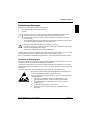
Thin Client Kurzanleitung/Brief Instructions FUTRO S400 Deutsch, English Sie haben... ... technische Fragen oder Probleme? Wenden Sie sich bitte an: ● unsere Hotline/Help Desk (siehe Help Desk-Liste oder im Internet: www.fujitsu-siemens.com/support/helpdesk.html) ● Ihren zuständigen Vertriebspartner ● Ihre Verkaufsstelle Weitere Informationen finden Sie im Handbuch "Sicherheit". Aktuelle Informationen zu unseren Produkten, Tipps, Updates usw. finden Sie im Internet: http://www.fujitsu-siemens.com Are there ... ... any technical problems or other questions you need clarified? Please contact: ● our Hotline/Help Desk (see the Help Desk list or go to: www.fujitsu-siemens.com/support/helpdesk.html) ● your sales partner ● your sales outlet Further information can be found in the "Safety" manual. The latest information on our products, tips, updates, etc., can be found on the Internet under: http://www.fujitsu-siemens.com Dieses Handbuch wurde erstellt von cognitas. Gesellschaft für Technik-Dokumentation mbH – www.cognitas.de Herausgegeben von/Published by Fujitsu Siemens Computers GmbH Printed in the Federal Republic of Germany AG 01/06 Ausgabe/Edition 1 Bestell-Nr./Order No.: A26361-K522-Z123-1-7419 Deutsch English FUTRO S400 Kurzanleitung Brief Instructions Ausgabe Januar 2006 January 2006 edition FUTRO ist ein Warenzeichen von Fujitsu Siemens Computers. Copyright © Fujitsu Siemens Computers GmbH 2005 Alle Rechte vorbehalten, insbesondere (auch auszugsweise) die der Übersetzung, des Nachdrucks, der Wiedergabe durch Kopieren oder ähnliche Verfahren. Zuwiderhandlungen verpflichten zu Schadenersatz. Alle Rechte vorbehalten, insbesondere für den Fall der Patenterteilung oder GM-Eintragung. Liefermöglichkeiten und technische Änderungen vorbehalten. Dieses Handbuch wurde erstellt von cognitas. Gesellschaft für Technik-Dokumentation mbH www.cognitas.de FUTRO is a trademarks of Fujitsu Siemens Computers. Copyright © Fujitsu Siemens Computers GmbH 2006 All rights, including rights of translation, reproduction by printing, copying or similar methods, even of parts are reserved. Offenders will be liable for damages. All rights, including rights created by patent grant or registration of a utility model or design, are reserved. Delivery subject to availability. Right of technical modification reserved. This manual was produced by cognitas. Gesellschaft für Technik-Dokumentation mbH www.cognitas.de Inhalt Ihr FUTRO S400................................................................................................................................... 1 Darstellungsmittel......................................................................................................................... 1 CE-Kennzeichnung ...................................................................................................................... 1 Energiesparen, Entsorgung und Recycling .................................................................................. 1 Anschlüsse und Anzeige ...................................................................................................................... 2 Gerät aufstellen .................................................................................................................................... 3 Geräte anschließen .............................................................................................................................. 3 Bildschirm anschließen ................................................................................................................ 3 Maus anschließen ........................................................................................................................ 3 Tastatur anschließen.................................................................................................................... 4 Gerät an das Netzwerk (LAN) anschließen .......................................................................................... 4 Weitere externe Geräte anschließen.................................................................................................... 4 Externe Geräte an die parallele oder serielle Schnittstelle anschließen ...................................... 5 Externe Geräte an die USB-Schnittstellen anschließen............................................................... 6 Mikrofon, Kopfhörer und Line-Out-Geräte anschließen................................................................ 6 Netzadapter anschließen...................................................................................................................... 6 Gerät einschalten ................................................................................................................................. 6 Konfiguration ........................................................................................................................................ 7 BIOS-Setup aufrufen .................................................................................................................... 7 PXE-Systemstart .......................................................................................................................... 7 Systemerweiterungen........................................................................................................................... 9 Hinweise zu Baugruppen ............................................................................................................. 9 Gehäuse öffnen .......................................................................................................................... 10 Gehäuse schließen .................................................................................................................... 10 SmartCard-Leser einbauen ........................................................................................................ 11 SmartCard-Leser ausbauen ....................................................................................................... 12 PCI-Baugruppe einbauen ........................................................................................................... 13 PCI-Baugruppe ausbauen .......................................................................................................... 15 Module ein- und ausbauen......................................................................................................... 16 Lithium-Batterie tauschen........................................................................................................... 20 Technische Daten............................................................................................................................... 21 A26361-K522-Z123-1-7419, Ausgabe 1 Deutsch Ihr FUTRO S400... …ist ein universeller Netzwerk-Client. Das intelligente und flexible Terminal ist zuverlässig und leicht zu warten. Der Thin Client benötigt keine Lüfter und keine Festplatte. Dadurch ist er besonders leise im Betrieb. Das Betriebssystem ist auf einem Compact Flash installiert. Darstellungsmittel In dieser Kurzbeschreibung werden folgende Darstellungsmittel verwendet: kennzeichnet Hinweise, bei deren Nichtbeachtung Ihre Gesundheit, die Funktionsfähigkeit Ihres Systems oder die Sicherheit Ihrer Daten gefährdet ist. ! kennzeichnet wichtige Informationen für den sachgerechten Umgang mit dem System. i ► kennzeichnet einen Arbeitsschritt, den Sie ausführen müssen. Diese Schrift stellt Bildschirmausgaben dar. Diese Schrift kennzeichnet Programm-Namen, Befehle oder Menüpunkte. "Anführungszeichen" kennzeichnen Kapitelnamen, Namen von Datenträgern und Begriffe, die hervorgehoben werden sollen. CE-Kennzeichnung Dieses Gerät erfüllt in der ausgelieferten Ausführung die Anforderungen der EGRichtlinien 89/336/EWG "Elektromagnetische Verträglichkeit" und 73/23/EWG "Niederspannungsrichtlinie". Energiesparen, Entsorgung und Recycling Informationen zu diesen Themen finden Sie auf der mitgelieferten CD "Drivers & Utilities". A26361-K522-Z123-1-7419, Ausgabe 1 Deutsch - 1 Kurzbeschreibung Anschlüsse und Anzeige Für den Anschluss von peripheren Geräten wie Maus, Tastatur oder Chipkartenleser stehen Ihnen an Vorder- und Rückseite des Geräts folgende Schnittstellen zur Verfügung. Vorderansicht Rückansicht 1= 2= 3= 4= 5= 6= 9= 10 = 11 = 12 = 13 = 14 = 15 = 16 = 17 = 18 = 7= Ein-/Ausschalter Betriebsanzeige Anzeige für SmartCard-Leser SmartCard-Leser Flashspeicherzugriff Kopfhöreranschluss, Audioausgang (Line out) Mikrofonanschluss 8 = USB-Anschlüsse (Universal Serial Bus) RJ45-LAN-Anschluss (Local Area Network) Einbauplatz für Module PS/2-Mausanschluss PS/2-Tastaturanschluss Bildschirmanschluss Serielle Schnittstelle USB-Anschlüsse (Universal Serial Bus) Audioausgang (Line out) Gleichspannungsbuchse (DC IN) Parallele Schnittstelle/Drucker 19 = PCI-Steckplatz Eine Kensington Lock-Vorrichtung finden Sie unten links am Gerät. Deutsch - 2 A26361-K522-Z123-1-7419, Ausgabe 1 Kurzbeschreibung Die Anschlüsse finden Sie an Vorder- und Rückseite des Geräts. Welche Anschlüsse an Ihrem Gerät verfügbar sind, hängt davon ab, welche Ausbaustufe Sie gewählt haben. Die Standardanschlüsse sind durch die nachfolgenden oder durch ähnliche Symbole gekennzeichnet. Tastaturanschluss PS/2-Mausanschluss Serielle Schnittstelle Parallele Schnittstelle/Drucker Bildschirmanschluss Kopfhörer Mikrofonanschluss Audioausgang (Line out) Audioeingang (Line in) USB - Universal Serial Bus LAN LAN-Anschluss DVI-Schnittstelle Gerät aufstellen ! ► Damit das Gehäuse ausreichend belüftet wird und um Überhitzung zu vermeiden, darf das Gerät nur in senkrechter Betriebslage mit befestigtem Standfuß betrieben werden. Schieben Sie das Gerät von vorne nach hinten in den Standfuß, bis dieser auf der rechten Seite einrastet. Geräte anschließen Bildschirm anschließen ► Bereiten Sie den Bildschirm vor, wie in der Betriebsanleitung zum Bildschirm beschrieben (z. B. Leitungen stecken). ► Stecken Sie die Datenleitung in den Bildschirmanschluss ► Schließen Sie die Netzleitung des Bildschirms an eine geerdete Schutzkontakt-Steckdose an. des Geräts. Maus anschließen PS/2-Maus anschließen ► Schließen Sie die PS/2-Maus an den PS/2-Mausanschluss A26361-K522-Z123-1-7419, Ausgabe 1 des Geräts an. Deutsch - 3 Kurzbeschreibung USB-Maus anschließen ► Schließen Sie die USB-Maus an den USB-Anschluss des Geräts an. Tastatur anschließen Standard-Tastatur anschließen Verwenden Sie nur die mitgelieferte Tastaturleitung. ► Stecken Sie den rechteckigen Stecker der Tastaturleitung in die rechteckige Buchse an der Unterseite oder an der Rückseite der Tastatur. ► Stecken Sie den runden Stecker der Tastaturleitung in den Tastaturanschluss Geräts. des USB-Tastatur anschließen Verwenden Sie nur die mitgelieferte Tastaturleitung. ► Stecken Sie den rechteckigen Stecker der Tastaturleitung in die Buchse an der Unterseite oder an der Rückseite der Tastatur. ► Stecken Sie den flachen rechteckigen USB-Stecker der Tastaturleitung in einen USBdes Geräts. Anschluss Gerät an das Netzwerk (LAN) anschließen ► Schließen Sie die 10/100-Base-T-Netzleitung an den LAN-Anschluss RJ45 an. Weitere externe Geräte anschließen ! Lesen Sie die Dokumentation zum externen Gerät, bevor Sie es anschließen. Außer bei USB-Geräten müssen die Netzstecker gezogen sein, wenn Sie externe Geräte anschließen! Bei Gewitter dürfen Sie Leitungen weder stecken noch lösen. Fassen Sie beim Lösen einer Leitung immer am Stecker an. Ziehen Sie nicht an der Leitung! Halten Sie beim Anschließen oder Lösen von Leitungen die nachfolgend beschriebene Reihenfolge ein. i Die Funktionalität der anschließbaren externen Geräte hängt vom verwendeten Betriebssystem ab. Welche externen Geräte angeschlossen werden können und weitere detaillierte Informationen finden Sie im Internet unter www.myelux.com Deutsch - 4 A26361-K522-Z123-1-7419, Ausgabe 1 Kurzbeschreibung Leitungen anschließen ► Alle betroffenen Geräte ausschalten. ► Die Netzstecker aller betroffenen Geräte aus den Schutzkontakt-Steckdosen ziehen. ► Alle Leitungen am Gerät und an den Peripheriegeräten stecken. Beachten Sie auf jeden Fall die Sicherheitshinweise im Kapitel "Wichtige Hinweise". ► Alle Datenübertragungsleitungen in die vorgesehenen Steckvorrichtungen der Daten-/Fernmeldenetze stecken. ► Alle Netzstecker in die Schutzkontakt-Steckdosen stecken. Leitungen lösen ► Alle betroffenen Geräte ausschalten. ► Die Netzstecker aller betroffenen Geräte aus den Schutzkontakt-Steckdosen ziehen. ► Alle Datenübertragungsleitungen aus den Steckvorrichtungen der Daten-/Fernmeldenetze ziehen. ► Alle Leitungen am Gerät und an den Peripheriegeräten lösen. i USB-Geräte sind hot-plug-fähig. Daher können die Leitungen von USB-Geräten bei eingeschaltetem System angeschlossen und gelöst werden. Weitere Informationen finden Sie im Abschnitt "Externe Geräte an die USB-Schnittstellen anschließen" und in der Dokumentation zu den USB-Geräten. Externe Geräte an die parallele oder serielle Schnittstelle anschließen An die parallele und die serielle Schnittstelle können Sie externe Geräte anschließen (z. B. einen Drucker oder ein Modem). ► Schließen Sie die Datenleitung an das externe Gerät an. ► Schließen Sie die Datenleitung je nach Gerät an die parallele Schnittstelle an. Schnittstelle oder die serielle Eine genaue Beschreibung, wie Sie das externe Gerät an die passende Schnittstelle anschließen, entnehmen Sie der Dokumentation zum externen Gerät. i Einstellungen der Schnittstellen Sie können die Einstellungen der Schnittstellen (z. B. Adresse, Interrupt) im BIOS-Setup ändern. Gerätetreiber Die Geräte, die Sie an die parallele oder serielle Schnittstelle anschließen, benötigen Treiber. Viele Treiber sind bereits in Ihrem Betriebssystem enthalten. Wenn der erforderliche Treiber fehlt, installieren Sie ihn. Aktuelle Treiber sind meist im Internet erhältlich oder werden auf einem Datenträger mitgeliefert. A26361-K522-Z123-1-7419, Ausgabe 1 Deutsch - 5 Kurzbeschreibung Externe Geräte an die USB-Schnittstellen anschließen An die USB-Schnittstellen können Sie eine Vielzahl externer Geräte anschließen (z. B. Drucker, Scanner, Modem oder Tastatur). i USB-Geräte sind hot-plug-fähig. Daher können die Leitungen von USB-Geräten bei eingeschaltetem System angeschlossen und gelöst werden. Weitere Informationen finden Sie in der Dokumentation zu den USB-Geräten. ► Schließen Sie die Datenleitung an das externe Gerät an. ► Schließen Sie die Datenleitung an eine USB-Schnittstelle i an. Gerätetreiber Die Geräte, die Sie an eine der USB-Schnittstellen anschließen, benötigen üblicherweise keine eigenen Treiber, da die notwendige Software bereits im Betriebssystem enthalten ist. Wenn das USB-Gerät jedoch eine eigene Software benötigt, installieren Sie diese von dem Datenträger, der mit dem USB-Gerät geliefert wurde. Mikrofon, Kopfhörer und Line-Out-Geräte anschließen ► Schließen Sie das Mikrofon an den Mikrofonanschluss an. ► Schließen Sie den Kopfhörer an den Kopfhöreranschluss an. ► Schließen Sie Line-Out-Geräte an den Audioausgang an. Netzadapter anschließen ► Schließen Sie die Netzadapterleitung an das Gerät an. ► Schließen Sie die Netzleitung an den Netzadapter an. ► Schließen Sie die Netzleitung an eine geerdete Schutzkontakt-Steckdose an. Gerät einschalten ► Schalten Sie den Bildschirm ein (siehe Betriebsanleitung des Bildschirms). ► Drücken Sie den Ein-/Ausschalter an der Vorderseite des Geräts. Die Betriebsanzeige leuchtet. Das Gerät startet mit dem dem embedded Betriebssystem. Deutsch - 6 A26361-K522-Z123-1-7419, Ausgabe 1 Kurzbeschreibung Konfiguration BIOS-Setup aufrufen ► Wenn das System startet, drücken Sie (eventuell mehrmals) die Taste Del / Entf . Das BIOS-Setup wird gestartet. Sie erreichen weitere Einstellmöglichkeiten im BIOS-Setup, wenn Sie eines der Register auswählen. PXE-Systemstart ► Wenn Sie das Gerät mit dem Ein-/Ausschalter eingeschaltet haben, drücken Sie beim Start des Systems (eventuell mehrmals) die Taste F12 . Das Boot-Menü wird angezeigt. ► Wählen Sie die gewünschte Boot-Möglichkeit. Konfigurationsmenü des PXE-Systemstarts aufrufen ► Drücken Sie die Tastenkombination + F10 , während Realtek RTL8139(X)/8130/810X Boot Agent angezeigt wird. Auf dem Bildschirm erscheint folgende oder eine ähnliche Anzeige: Realtek RTL 8139 / 8130 / 810X BOOT Agent Configuration Menu v2.13 Network Boot Protokol PXE [RLP] Boot Order Int19h [PnP/BEV(BBS) /ROM Disabled/ Int18h] Show Config Message Enable [Disable] Show Message Time 3 Seconds [5 / 8] <ESC> Quit <Space> Change Value <Enter> Next Option <F4> Save/Quit Bildschirm des Konfigurationsmenüs A26361-K522-Z123-1-7419, Ausgabe 1 Deutsch - 7 Kurzbeschreibung Folgende Einstellungen sind möglich: Network Boot Protocol: PXE (Standard) oder RPL Angabe des verwendeten SystemstartProtokolls. Boot Order: Int 19h Es wird immer zuerst das Netzwerk gestartet, bevor die lokalen Geräte aktiviert werden. PnP/ BEV (BBS) Wenn ein BBS-BIOS (BIOS Boot Specification) vorhanden ist, wird das System durch das BBSBIOS gestartet. ROM Disabled Der komplette Mechanismus zum Systemstart ist ausgeschaltet. Das System kann nur noch über die lokalen Geräte aktiviert werden. Int 18h Es werden die Geräte aktiviert, die im BIOSSetup eingestellt wurden. Show Config Message: Die folgende Meldung kann während des Systemstarts ein- oder ausgeschaltet werden: Realtek RTL8139(X)/8130/810X Boot Agent Press Shift-F10 to configure ……. Show Message Time: Gibt die Zeit in Sekunden an, die die folgende Meldung während des Systemstarts zu sehen ist: Realtek RTL8139(X)/8130/810X Boot Agent Press Shift-F10 to configure ……. Die Einstellungen sind erst nach dem Abspeichern und einem erneuten PXE-Systemstart wirksam. Deutsch - 8 A26361-K522-Z123-1-7419, Ausgabe 1 Kurzbeschreibung Systemerweiterungen Optional können Sie folgende Komponenten einbauen: ● eine PCI-Baugruppe (Länge maximal 155 mm) ● ein Modul i Es kann sinnvoll sein, wenn Sie sich einige Teile dieses Kapitels ausdrucken, da das Gerät beim Ein-/Ausbau von Systemerweiterungen ausgeschaltet sein muss. Eventuell ist für eine Systemerweiterung oder Hardware-Hochrüstung ein Update des BIOS notwendig. Achten Sie beim Einbauen von Komponenten mit großer Wärmeentwicklung darauf, dass die maximal zulässige Temperatur nicht überschritten wird. ! Beachten Sie die Sicherheitshinweise im Handbuch "Sicherheit". Das Gerät muss beim Ein-/Ausbau von Systemerweiterungen ausgeschaltet sein und darf sich nicht im Energiesparmodus befinden. Ziehen Sie den Netzstecker, bevor Sie das Gerät öffnen. In diesem Kapitel werden alle Tätigkeiten beschrieben, die Sie ausführen müssen, wenn Sie in Ihrem Gerät Hardware-Änderungen (z. B. Baugruppen einbauen) durchführen möchten. Bevor Sie neue Module und/oder Baugruppen einbauen, lesen Sie die mitgelieferte Dokumentation. Hinweise zu Baugruppen Gehen Sie sorgfältig mit den Verriegelungsmechanismen (Rastnasen und Zentrierbolzen) um, wenn Sie Baugruppen oder Komponenten auf Baugruppen austauschen. Um Schäden der Baugruppe oder der darauf befindlichen Bauteile und Leiterbahnen zu vermeiden, bauen Sie Baugruppen mit Sorgfalt ein und aus. Achten Sie darauf, Erweiterungsbaugruppen gerade einzusetzen. Verwenden Sie niemals scharfe Gegenstände (Schraubendreher) als Hebelwerkzeuge. Baugruppen mit elektrostatisch gefährdeten Bauelementen (EGB) können durch den abgebildeten Aufkleber gekennzeichnet sein. Wenn Sie Baugruppen mit EGB handhaben, müssen Sie folgende Hinweise unbedingt beachten: ● Sie müssen sich statisch entladen (z. B. durch Berühren eines geerdeten Gegenstandes), bevor Sie mit Baugruppen arbeiten. ● Verwendete Geräte und Werkzeuge müssen frei von statischer Aufladung sein. ● Fassen Sie die Baugruppen nur am Rand an. ● Berühren Sie keine Anschluss-Stifte oder Leiterbahnen auf der Baugruppe. A26361-K522-Z123-1-7419, Ausgabe 1 Deutsch - 9 Kurzbeschreibung Gehäuse öffnen Wenn Sie Ihr System erweitern möchten, müssen Sie zuerst das Gehäuse öffnen. ► Schalten Sie das Gerät aus. ► Ziehen Sie den Netzstecker aus der Schutzkontakt-Steckdose. ► Ziehen Sie alle Leitungen vom Gerät. ► Ziehen Sie das Gerät aus dem Standfuß heraus und legen Sie es waagerecht auf eine feste Oberfläche. ► Entfernen Sie die beiden Schrauben (1) und ziehen Sie die Frontblende nach vorne weg (2). ► Entfernen Sie die beiden Schrauben (3) an der Rückseite des Geräts und heben Sie den Gehäusedeckel vom Gerät (4). ! Beachten Sie, dass verschiedene Komponenten auf dem Mainboard sehr heiß sein können, wenn das Gerät vor kurzem noch aktiv war. Diese Komponenten können durch folgendes Symbol gekennzeichnet sein. Gehäuse schließen ► Setzen Sie den Gehäusedeckel wieder auf das Gerät und befestigen Sie ihn mit den beiden Schrauben (3) an der Rückseite des Geräts. Achten Sie darauf, dass die Leitungen nicht zwischen Gehäuse und Bauteilen eingeklemmt werden! ► Schieben Sie die Frontblende auf das Gerät und befestigen Sie sie mit den beiden Schrauben (1) an den Seiten des Geräts. Deutsch - 10 A26361-K522-Z123-1-7419, Ausgabe 1 Kurzbeschreibung ► Schieben Sie das Gerät von vorne nach hinten in den Standfuß, bis dieser auf der rechten Seite einrastet. ► Stecken Sie alle zuvor entfernten Leitungen. SmartCard-Leser einbauen Sie können, sofern nicht bereits vorhanden, einen SmartCard-Leser einbauen. SmartCard-Leser an Halterung befestigen a 2 1 ► Schieben Sie den SmartCard-Leser in Pfeilrichtung (1) mit der Bauteilseite nach unten in die Führung der Halterung (a). ► Befestigen Sie den SmartCard-Leser mit den Schrauben (2) an der Halterung. ► Öffnen Sie das Gehäuse (siehe "Gehäuse öffnen"). ► Brechen Sie die Plastiksperre hinter dem Einschub an der Frontblende ab. ► Befestigen Sie die Halterung mit den Schrauben (1) am Gehäusedeckel. ► Schließen Sie die Leitung am SmartCardLeser (2) an. 2 SmartCard-Leser am Gerät befestigen 1 2 1 A26361-K522-Z123-1-7419, Ausgabe 1 Deutsch - 11 Kurzbeschreibung ► Schließen Sie die Leitung am Stecker (1) auf dem Mainboard an und führen Sie sie, wie in der Abbildung dargestellt (2). ► Schließen Sie das Gehäuse (siehe "Gehäuse schließen"). Achten Sie darauf, dass die Leitungen nicht zwischen Gehäuse und Bauteilen eingeklemmt werden! SmartCard-Leser ausbauen ► Öffnen Sie das Gehäuse (siehe "Gehäuse öffnen"). SmartCard-Leser vom Gerät lösen ► Ziehen Sie die Leitung vom SmartCardLeser (1) und vom Mainboard. ► Lösen Sie die Schrauben (2). ► Schließen Sie das Gehäuse (siehe "Gehäuse schließen"). 2 1 2 Deutsch - 12 A26361-K522-Z123-1-7419, Ausgabe 1 Kurzbeschreibung PCI-Baugruppe einbauen Sie können nur PCI-Baugruppen mit einer maximalen Länge von 150 mm einbauen. ► Nehmen Sie auf der PCI-Baugruppe die erforderlichen Einstellungen vor. ► Öffnen Sie das Gehäuse (siehe "Gehäuse öffnen"). ! ► Entfernen Sie die Risercard (1). ► Lösen Sie die Schraube (2), um den dahinter liegenden Riegel zu entfernen. ► Lösen Sie die Schrauben (3) und (4), um die Rückseitenabdeckung des Einbauplatzes von Ihrem Gerät zu entfernen. Werfen Sie die Rückseitenabdeckung nicht weg. Wenn Sie die PCI-Baugruppe wieder entfernen, müssen Sie die Rückseitenabdeckung wegen der Kühlung, des Brandschutzes und der einzuhaltenden EMV-Vorschriften (Vorschriften zur elektromagnetischen Verträglichkeit) wieder einbauen. A26361-K522-Z123-1-7419, Ausgabe 1 ► Stecken Sie Ihre PCI-Baugruppe an die Risercard. ► Stecken Sie die Risercard von innen in den Einbauplatz und drücken Sie sie in Pfeilrichtung (1), bis sie spürbar einrastet. ► Befestigen Sie den Riegel mit der Schraube (2), um die PCI-Baugruppe zu fixieren. Deutsch - 13 Kurzbeschreibung ► i ► Befestigen Sie die Schrauben (4) und gegebenenfalls (3), um die PCI-Baugruppe an der Rückseite des Geräts zu fixieren. Manche PCI-Baugruppen haben keine Öffnung für die Schraube (3). In diesem Fall befestigen Sie die PCI-Baugruppe nur mit der Schraube (4). Schließen Sie das Gehäuse (siehe "Gehäuse schließen"). Deutsch - 14 A26361-K522-Z123-1-7419, Ausgabe 1 Kurzbeschreibung PCI-Baugruppe ausbauen ► Öffnen Sie das Gehäuse (siehe "Gehäuse öffnen"). ! ► Lösen Sie die Schrauben (4) und gegebenenfalls (3). ► Lösen Sie die Schraube (2), um die PCIBaugruppe zu entfernen. ► Ziehen Sie die Risercard mit der angesteckten PCI-Baugruppe aus dem Einbauplatz heraus (1) und nehmen Sie sie aus dem Gehäuse. ► Lösen Sie die PCI-Baugruppe von der Risercard. Sie müssen die Rückseitenabdeckung wegen der Kühlung, des Brandschutzes und der einzuhaltenden EMV-Vorschriften (Vorschriften zur elektromagnetischen Verträglichkeit) wieder einbauen. A26361-K522-Z123-1-7419, Ausgabe 1 Deutsch - 15 Kurzbeschreibung ► ► Stecken Sie die Risercard wieder in ihren Steckplatz (1). ► Befestigen Sie den Riegel mit der Schraube (2). ► Bauen Sie die Rückseitenabdeckung wieder ein, indem Sie diese von innen in den Einbauplatz setzen und mit den Schrauben (3) und (4) an der Rückseite des Geräts befestigen. Schließen Sie das Gehäuse (siehe "Gehäuse schließen"). Module ein- und ausbauen Sie können ein Modul (z. B. WLAN-Modul oder DVI-Modul) in den Einbauplatz einbauen. Modul mit direktem Mainboard-Stecker (z. B. DVI-Modul) einbauen ► Öffnen Sie das Gehäuse (siehe "Gehäuse öffnen"). ► ! Lösen Sie die Schrauben (1) und nehmen Sie die Abdeckung des Einbauplatzes heraus. Werfen Sie die Abdeckung des Einbauplatzes nicht weg. Wenn Sie das Modul wieder entfernen, müssen Sie die Abdeckung des Einbauplatzes wegen der Kühlung, des Brandschutzes und der einzuhaltenden EMV-Vorschriften (Vorschriften zur elektromagnetischen Verträglichkeit) wieder einbauen. ► Setzen Sie die Blechhalterung, die Sie mit dem Modul erhalten haben, in das Gehäuse und sichern Sie es mit den Schrauben (1). ► Setzen Sie das Modul von oben so in das Gehäuse, dass es auf den Schraublöchern der Blechhalterung liegt. Achten Sie darauf, dass der Stecker an der Unterseite des Moduls genau auf dem entsprechenden Stecker des Mainboards liegt. Deutsch - 16 A26361-K522-Z123-1-7419, Ausgabe 1 Kurzbeschreibung ► ► Drücken Sie das Modul vorsichtig bis zum Anschlag in Pfeilrichtung (1). ► Befestigen Sie das Modul mit den Schrauben (2) an der Blechhalterung. Schließen Sie das Gehäuse (siehe "Gehäuse schließen"). Modul mit direktem Mainboard-Stecker (z. B. DVI-Modul) ausbauen ► ► Öffnen Sie das Gehäuse (siehe "Gehäuse öffnen"). ► Lösen Sie die Schrauben (1) von der Blechhalterung. ► Ziehen Sie das Modul vorsichtig in Pfeilrichtung (2) aus dem Gehäuse. ► Lösen Sie die Schrauben (1) der Blechhalterung. ► Entfernen Sie die Blechhalterung. ► Wenn Sie kein anderes Modul einbauen wollen, bauen Sie die Abdeckung des Einbauplatzes wieder ein. Schließen Sie das Gehäuse (siehe "Gehäuse schließen"). A26361-K522-Z123-1-7419, Ausgabe 1 Deutsch - 17 Kurzbeschreibung Modul ohne direkten Mainboard-Stecker (z. B. WLAN-Modul) einbauen ► Öffnen Sie das Gehäuse (siehe "Gehäuse öffnen"). ► ! Lösen Sie die Schrauben (1) und nehmen Sie die Abdeckung des Einbauplatzes heraus. Werfen Sie die Abdeckung des Einbauplatzes nicht weg. Wenn Sie das Modul wieder entfernen, müssen Sie die Abdeckung des Einbauplatzes wegen der Kühlung, des Brandschutzes und der einzuhaltenden EMV-Vorschriften (Vorschriften zur elektromagnetischen Verträglichkeit) wieder einbauen. WLAN-Modul zusammenbauen ► Schieben Sie die WLAN-Karte von hinten in die Blechhalterung, bis die Löcher in der WLAN-Karte mit den entsprechenden Löchern (1) der Blechhalterung übereinstimmen. ► Legen Sie die Kunststoffabdeckung (2) auf die WLAN-Karte. ► Befestigen Sie die Kunststoffabdeckung und die WLAN-Karte mit den Schrauben (1) an der Blechhalterung. ► Schließen Sie die Leitung am Stecker der WLAN-Karte (3) an. WLAN-Modul einbauen ► Drehen Sie das WLAN-Modul um. ► Fädeln Sie das WLAN-Modul von innen in den Einbauplatz. Deutsch - 18 ► Schieben Sie die Plastikkappe von außen über das hervorstehende Ende des WLANModuls. ► Befestigen Sie WLAN-Modul und Plastikkappe mit den Schrauben (1). A26361-K522-Z123-1-7419, Ausgabe 1 Kurzbeschreibung ► Schließen Sie die Leitung am Stecker (1) auf dem Mainboard an und führen Sie sie, wie in der Abbildung dargestellt (2). ► Schließen Sie das Gehäuse (siehe "Gehäuse schließen"). Achten Sie darauf, dass die Leitungen nicht zwischen Gehäuse und Bauteilen eingeklemmt werden! Modul ohne direkten Mainboard-Stecker (z. B. WLAN-Modul) ausbauen ► Öffnen Sie das Gehäuse (siehe "Gehäuse öffnen"). ► Ziehen Sie die Leitung von Modul und Mainboard. ► ► Lösen Sie die Schrauben (1). ► Nehmen Sie die Plastikkappe ab. ► Ziehen Sie das WLAN-Modul vorsichtig aus dem Einbauplatz. ► Wenn Sie kein anderes Modul einbauen wollen, bauen Sie die Abdeckung des Einbauplatzes wieder ein. Schließen Sie das Gehäuse (siehe "Gehäuse schließen"). A26361-K522-Z123-1-7419, Ausgabe 1 Deutsch - 19 Kurzbeschreibung Lithium-Batterie tauschen Damit die Systeminformation dauerhaft gespeichert werden kann, ist eine Lithium-Batterie eingebaut, die den CMOS-Speicher mit Strom versorgt. Wenn die Spannung der Batterie zu niedrig oder die Batterie leer ist, wird eine entsprechende Fehlermeldung ausgegeben. Die Lithium-Batterie muss dann ausgetauscht werden. ! Bei unsachgemäßem Austausch der Lithium-Batterie besteht Explosionsgefahr! Die Lithium-Batterie darf nur durch identische oder vom Hersteller empfohlene Typen ersetzt werden. Wenden Sie sich an unseren Service. Die Lithium-Batterie gehört nicht in den Hausmüll. Sie wird vom Hersteller, Händler oder deren Beauftragten kostenlos zurückgenommen, um sie einer Verwertung oder Entsorgung zuzuführen. Achten Sie beim Austausch unbedingt auf die richtige Polung der Lithium-Batterie: Pluspol nach oben! Die Halterung der Lithium-Batterie gibt es in verschiedenen Ausführungen, die sich in ihrer Funktionsweise nicht unterscheiden. 3 2 2 3 1 ► Öffnen Sie das Gehäuse (siehe "Gehäuse öffnen"). ► Drücken Sie die Rastnase in Pfeilrichtung (1). Die Batterie springt etwas aus der Halterung heraus. ► Entfernen Sie die Batterie (2). ► Schieben Sie die neue Lithium-Batterie des identischen Typs in die Halterung (3) und drücken Sie sie nach unten, bis sie einrastet. ► Schließen Sie das Gehäuse (siehe "Gehäuse schließen"). Deutsch - 20 A26361-K522-Z123-1-7419, Ausgabe 1 Kurzbeschreibung Technische Daten Elektrische Daten Prozessor: AMD MX 1500 Nennspannungsbereich: 90 V - 265 V Abmessungen Breite/Tiefe/Höhe: 50 mm/180 mm/247 mm Gewicht im Grundausbau: ca. 1,6 kg (mit Standfuß) Umgebungsbedingungen Temperatur: ● Betrieb ● Transport 15 °C .... 35 °C -25 °C .... 60 °C Betauung ist im Betrieb nicht zulässig! Zu- und Ablufträume, um eine ausreichende Belüftung zu gewährleisten: ● ● ● ● links rechts hinten oben ! min. 200 mm min. 200 mm min. 200 mm min. 200 mm Es dürfen nicht mehrere Geräte übereinander gestapelt werden. A26361-K522-Z123-1-7419, Ausgabe 1 Deutsch - 21 Contents Your FUTRO S400... ............................................................................................................................ 1 Notational conventions ................................................................................................................. 1 CE marking................................................................................................................................... 1 Energy saving, disposal and recycling ......................................................................................... 1 FCC Class B Compliance Statement ........................................................................................... 2 Ports and indicator................................................................................................................................ 3 Setting up the device ............................................................................................................................ 4 Connecting devices .............................................................................................................................. 4 Connecting the monitor ................................................................................................................ 4 Connecting the mouse ................................................................................................................. 4 Connecting a keyboard................................................................................................................. 5 Connecting the device to the network (LAN) ........................................................................................ 5 Connecting other external devices ....................................................................................................... 5 Connecting external devices to the parallel or serial port............................................................. 6 Connecting external devices to the USB ports............................................................................. 6 Connecting microphone, headphones and line-out devices......................................................... 7 Connecting the mains adapter.............................................................................................................. 7 Switching the device on........................................................................................................................ 7 Configuration ........................................................................................................................................ 8 Calling BIOS Setup ...................................................................................................................... 8 PXE system boot .......................................................................................................................... 8 System expansions ............................................................................................................................ 10 Information about boards ........................................................................................................... 10 Opening the casing .................................................................................................................... 11 Closing the casing ...................................................................................................................... 11 Installing a SmartCard reader .................................................................................................... 12 Removing a SmartCard reader................................................................................................... 13 Installing PCI board .................................................................................................................... 14 Removing PCI board .................................................................................................................. 16 Installing and removing modules................................................................................................ 17 Replacing lithium battery ............................................................................................................ 21 Technical data .................................................................................................................................... 22 A26361-K522-Z123-1-7419, edition 1 English Your FUTRO S400... …is a universal network client. The intelligent, flexible terminal is reliable and easy to maintain. The thin client requires no fan and no hard disk. It therefore runs very quietly. The operating system is installed on a compact flash. Notational conventions The meanings of the symbols and fonts used in this short description are as follows: Pay particular attention to texts marked with this symbol. Failure to observe this warning endangers your life, destroys the system, or may lead to loss of data. ! Indicates important information which is required to use the system properly. i ► Text which follows this symbol describes activities that must be performed in the order shown. This font indicates screen outputs. This font indicates programme names, commands, or menu items. "Quotation marks" indicate names of chapters, data carriers, and terms that are being emphasised. CE marking The shipped version of this device complies with the requirements of the EEC directives 89/336/EEC "Electromagnetic compatibility" and 73/23/EEC "Low voltage directive". Energy saving, disposal and recycling Further information can be found on the "Drivers & Utilities" CD provided with your computer. A26361-K522-Z123-1-7419, edition 1 English - 1 Short description FCC Class B Compliance Statement The following statement applies to the products covered in this manual, unless otherwise specified herein. The statement for other products will appear in the accompanying documentation. NOTE: This equipment has been tested and found to comply with the limits for a "Class B" digital device, pursuant to Part 15 of the FCC rules and meets all requirements of the Canadian InterferenceCausing Equipment Standard ICES-003 for digital apparatus. These limits are designed to provide reasonable protection against harmful interference in a residential installation. This equipment generates, uses and can radiate radio frequency energy and, if not installed and used in strict accordance with the instructions, may cause harmful interference to radio communications. However, there is no guarantee that interference will not occur in a particular installation. If this equipment does cause harmful interference to radio or television reception, which can be determined by turning the equipment off and on, the user is encouraged to try to correct the interference by one or more of the following measures: ● ● ● ● Reorient or relocate the receiving antenna. Increase the separation between equipment and the receiver. Connect the equipment into an outlet on a circuit different from that to which the receiver is connected. Consult the dealer or an experienced radio/TV technician for help. Fujitsu Siemens Computers GmbH is not responsible for any radio or television interference caused by unauthorised modifications of this equipment or the substitution or attachment of connecting cables and equipment other than those specified by Fujitsu Siemens Computers GmbH. The correction of interferences caused by such unauthorised modification, substitution or attachment will be the responsibility of the user. The use of shielded I/O cables is required when connecting this equipment to any and all optional peripheral or host devices. Failure to do so may violate FCC and ICES rules. English - 2 A26361-K522-Z123-1-7419, edition 1 Short description Ports and indicator The following interfaces are provided on the front and back of the unit for the connection of peripheral devices such as a mouse, keyboard or chipcard reader. Front view Rear view 1= 2= 3= 4= 5= 6= 7= 9= 10 = 11 = 12 = 13 = 14 = 15 = 16 = 17 = 18 = ON/OFF switch Power-on indicator Indicator for SmartCard reader SmartCard reader Flash memory access Headphones port, audio output (Line out) Microphone jack 8 = USB ports (Universal Serial Bus) RJ45 socket (Local Area Network) Installation slot for modules PS/2 mouse port PS/2 keyboard port Monitor port Serial port USB ports (Universal Serial Bus) Audio output (Line out) DC jack (DC IN) Parallel interface / Printer 19 = PCI slot The device has a Kensington lock at the bottom left. A26361-K522-Z123-1-7419, edition 1 English - 3 Short description The connections are located on the front and back of the device. The ports available on your device depend on the configuration level you have selected. The standard ports are marked with the symbols shown below (or similar). Keyboard port PS/2 mouse port Serial port Parallel interface / Printer Monitor port Headphones Microphone jack Audio output (Line out) Audio input (Line in) USB - Universal Serial Bus LAN LAN port DVI interface Setting up the device ! ► So that the casing is sufficiently ventilated and to prevent overheating, the device may only be operated in the vertical operating position with the base foot attached. Slide your device into the base foot from the front toward the rear until it engages on the righthand side. Connecting devices Connecting the monitor ► Follow the instructions contained in the monitor manual to prepare the monitor for operation (e.g. connecting cables). ► Plug the data cable into the monitor port ► Plug the monitor power cable into the grounded mains outlet. of the device. Connecting the mouse Connecting a PS/2 mouse ► Connect the PS/2 mouse to the PS/2 mouse port English - 4 of the device. A26361-K522-Z123-1-7419, edition 1 Short description Connecting USB mouse ► Connect the USB mouse to the USB port of the device. Connecting a keyboard Connecting standard keyboard Use the supplied keyboard cable only. ► Plug the rectangular connector of the keyboard cable into the rectangular socket on the underside or on the rear of the keyboard. ► Plug the round plug of the keyboard cable into the keyboard port on the device. Connecting USB keyboard Use the supplied keyboard cable only. ► Plug the rectangular connector of the keyboard cable into the socket on the underside or on the rear of the keyboard. ► Insert the flat rectangular USB plug of the keyboard cable into a USB port of the device. Connecting the device to the network (LAN) ► Connect the 10/100 Base T network cable to the RJ45 LAN port. Connecting other external devices ! Read the documentation on the external device before connecting it. With the exception of USB devices, always remove all power plugs before connecting external devices! Do not connect or disconnect cables during a thunderstorm. Always take hold of the actual plug. Never unplug a cable by pulling the cable itself. Connect and disconnect the cables in the order described below. i The functionality of the connectable external devices is dependent on the operating system used. The external devices which can be connected and additional detailed information are available on the Internet at www.myelux.com Connecting cables ► Turn off all power and equipment switches. ► Remove all power plugs from the grounded mains outlets. ► Plug all cables into the device and peripherals. You must observe the information provided in the "Important notes" chapter. ► Plug all data communication cables into the utility sockets. ► Plug all power cables into the grounded mains outlets. A26361-K522-Z123-1-7419, edition 1 English - 5 Short description Disconnecting cables ► Turn off all power and equipment switches. ► Remove all power plugs from the grounded mains outlets. ► Unplug all data communication cables from the utility sockets. ► Unplug all cables from the device and peripherals. i USB devices are hot-pluggable. This means you can connect and disconnect devices while your operating system is running. Additional information can be found in the "Connecting external devices to the USB ports" section and in the documentation for the USB devices. Connecting external devices to the parallel or serial port External devices can be connected to the parallel or serial port (e.g. a printer or a modem). ► Connect the data cable to the external device. ► Depending on the device, connect the data cable to the parallel port or the serial port . For an exact description of how to connect external devices to the corresponding port, please see the external device documentation. i Port settings You can change the port settings (e.g. address, interrupt) in the BIOS Setup. Device drivers The devices connected to the parallel or serial port require drivers. Your operating system already includes many drivers. If the required drive is missing, install it. Current drivers are usually available on the Internet or will be supplied on a data carrier. Connecting external devices to the USB ports You can connect a wide range of external devices to the USB port (e.g. printer, scanner, modem or keyboard). i USB devices are hot-pluggable. This means you can connect and disconnect devices while your operating system is running. Additional information can be found in the documentation for the USB devices. ► Connect the data cable to the external device. ► Connect the data cable to a USB port i . Device drivers The devices you connect to the USB ports usually require no driver of their own, as the required software is already included in the operating system. However, if the USB device requires its own software, please install it from the data carrier provided with the USB device. English - 6 A26361-K522-Z123-1-7419, edition 1 Short description Connecting microphone, headphones and line-out devices ► Plug the connector of the microphone into the microphone jack. ► Connect the headphones to the headphones port. ► Connect line-out devices to the audio output. Connecting the mains adapter ► Connect the mains adapter cable to the device. ► Connect the power cable to the mains adapter. ► Plug the power cable into a grounded mains outlet. Switching the device on ► Switch the monitor on (see the operating manual for the monitor). ► Press the ON/OFF switch on the front of the device. The power-on indicator lights up. The device starts up with the embedded operating system. A26361-K522-Z123-1-7419, edition 1 English - 7 Short description Configuration Calling BIOS Setup ► When the system starts, press the Del key (several times if necessary). The BIOS-Setup will be started. Select one of the tabs to access other setting options in BIOS-Setup. PXE system boot ► If you started the device using the ON/OFF switch, press the F12 key (several times if necessary) when the system starts. The boot menu is displayed. ► Select the desired boot option. Calling the PXE system start configuration menu ► Press the key combination + F10 while Realtek RTL8139(X)/8130/810X Boot Agent is displayed. Following or a similar display appears on the screen: Realtek RTL 8139 / 8130 / 810X BOOT Agent Configuration Menu v2.13 Network Boot Protokol PXE [RLP] Boot Order Int19h [PnP/BEV(BBS) /ROM Disabled/ Int18h] Show Config Message Enable [Disable] Show Message Time 3 Seconds [5 / 8] <ESC> Quit <Space> Change Value <Enter> Next Option <F4> Save/Quit Screen of configuration menu English - 8 A26361-K522-Z123-1-7419, edition 1 Short description The following settings are possible: Network Boot Protocol: PXE (standard) or RPL Specification of the system start-up protocol used. Boot Order: Int 19h The network is always started first before the local devices are activated. PnP/ BEV (BBS) If a BBS-BIOS (BIOS Boot Specification) exists, the system is started by the BBS-BIOS. ROM Disabled The entire mechanism for the system start-up is deactivated. The system can only be activated via the local devices. Int 18h The devices set in BIOS-Setup are enabled. Show Config Message: The following message can be activated or deactivated during the system start-up: Realtek RTL8139(X)/8130/810X Boot Agent Press Shift-F10 to configure ……. Show Message Time: Indicates the time in seconds for which the following message is displayed during the system start-up: Realtek RTL8139(X)/8130/810X Boot Agent Press Shift-F10 to configure ……. The settings are not effective until after saving and another PXE system start-up. A26361-K522-Z123-1-7419, edition 1 English - 9 Short description System expansions You can also install the following optional components: ● a PCI board (maximum length of 155 mm) ● a module i As the device has to be shut down in order to install/deinstall system hardware components, it is a good idea to print out the relevant sections of this chapter. It may be necessary to update the BIOS when carrying out a system expansion or hardware upgrade. When installing components that become very hot, make sure that the maximum permissible temperature is not exceeded. ! Observe the safety precautions in the "Safety" manual. The device must be switched off when installing/removing the system expansions and may not be in the energy-saving mode. Remove the power plug before opening the device. This chapter describes all activities you must carry out when you want to make changes to the hardware of your device (e.g. install boards). Read the supplied documentation before installing new modules and/or boards. Information about boards Take care with the locking mechanisms (catches and centring pins) when you are replacing boards or components on boards. To prevent damage to the board or the components and conductors on it, please take care when you insert or remove boards. Make sure expansion boards are inserted straightly. Never use sharp objects (screwdrivers) for leverage. Boards with electrostatic sensitive devices (ESD) are identifiable by the label shown. When you handle boards fitted with ESDs, you must, under all circumstances, observe the following points: English - 10 ● You must always discharge static build up (e.g. by touching a grounded object) before working. ● The equipment and tools you use must be free of static charges. ● Always hold boards with ESDs by their edges. ● Never touch pins or conductors on boards fitted with ESDs. A26361-K522-Z123-1-7419, edition 1 Short description Opening the casing If you want to upgrade your system, you must first open the casing. ► Switch off the device. ► Pull the power plug out of the mains outlet. ► Disconnect all cables of the device. ► Pull the device out of the base and lay it horizontally on a firm surface. ► Remove the two screws (1) and pull the front cover off to the front (2). ► Remove the two screws (3) on the rear of the device and lift off the casing cover (4). ! Note that some components on the mainboard may be very hot if the device was in use shortly before the casing was removed. These components can be marked with the following symbol. Closing the casing ► Replace the casing on the device and secure it in position with the two screws (3) at the rear of the device. Make sure that the cables are not trapped between the casing and the components. ► Push the front cover onto the device and secure it in position with the two screws (1) at the sides of the device. ► Slide your device into the base foot from the front toward the rear until it engages on the righthand side. ► Connect all the cables removed before. A26361-K522-Z123-1-7419, edition 1 English - 11 Short description Installing a SmartCard reader If not already installed, you can fit a SmartCard reader. Screwing SmartCard reader onto carrier a 2 1 ► Push the SmartCard reader - with the component side facing downwards - in the direction of the arrow (1) into the guide (a). ► Fasten the SmartCard reader with the screws (2) onto the carrier. ► Open the casing (see "Opening the casing"). ► Break off the plastic lock behind the plug-in module on the front cover. ► Fasten the carrier with the screws (1) on the casing cover. ► Connect the cable to the SmartCard reader (2). ► Attach the cable to the connector (1) on the mainboard and route it as shown in the diagram (2). ► Close the casing (see "Closing the casing"). Make sure that the cables are not trapped between the casing and the components. 2 Fixing SmartCard reader onto device 1 2 1 English - 12 A26361-K522-Z123-1-7419, edition 1 Short description Removing a SmartCard reader ► Open the casing (see "Opening the casing"). Removing SmartCard reader from device ► Disconnect the cable from the SmartCard reader (1) and from the mainboard. ► Loosen the screws (2). ► Close the casing (see "Closing the casing"). 2 1 2 A26361-K522-Z123-1-7419, edition 1 English - 13 Short description Installing PCI board You can only install PCI boards with a maximum length of 150 mm. ► Make the required settings for the PCI board. ► Open the casing (see "Opening the casing"). ! ► Remove the riser card (1). ► Unscrew the screw (2) to remove the lock located behind it. ► Unscrew the screws (3) and (4) to remove the rear slot cover plate of the installation slot from your device. Do not dispose of the rear slot cover plate. If you remove the PCI board again, you must reinstall the rear slot cover plate due to cooling, fire protection and the EMC regulations (regulations on electromagnetic compatibility) to be complied with. English - 14 ► Insert your PCI board on the riser card. ► Insert the riser card from the inside into the installation slot and push it in the direction of the arrow (1) until it perceptibly locks into position. ► Secure the lock with the screw (2) to secure the PCI board. A26361-K522-Z123-1-7419, edition 1 Short description ► i ► Screw in the screws (4) and (3), if present, to secure the PCI board on the back of the device. Some PCI boards do not have the opening for screw (3). In this case, only secure the PCI board with screw (4). Close the casing (see "Closing the casing"). A26361-K522-Z123-1-7419, edition 1 English - 15 Short description Removing PCI board ► Open the casing (see "Opening the casing"). ! ► Unscrew the screws (4) and, if necessary, (3). ► Unscrew the screw (2) to remove the PCI board. ► Pull the riser card with the inserted PCI board out of the installation slot (1) and remove it from the housing. ► Remove the PCI board from the riser card. You must reinstall the rear cover due to cooling, fire protection and the EMC regulations (regulations on electromagnetic compatibility) to be complied with. English - 16 A26361-K522-Z123-1-7419, edition 1 Short description ► ► Insert the riser card in its slot (1) again. ► Secure the lock with the screw (2). ► Reinstall the rear cover by inserting it in the installation slot from the inside and securing it with the screws (3) and (4) on the back of the unit. Close the casing (see "Closing the casing"). Installing and removing modules You can fit a module (e.g. WLAN module or DVI module) in the installation slot. Installing a module with a direct mainboard connector (e.g. DVI module) ► Open the casing (see "Opening the casing"). ► ! Unscrew the screws (1) and remove the cover of the installation slot. Do not dispose of the cover of the bay. For cooling, protection against fire and in order to comply with EMC regulations, you must refit the cover of the bay if you remove the module. ► Insert the holder plate supplied with the module into the casing and secure it with the screws (1). ► Insert the module from above into the casing so that it sits on the screw holes of the holder plate. Make sure that the connector on the underside of the module lies up against the corresponding connector on the mainboard. A26361-K522-Z123-1-7419, edition 1 English - 17 Short description ► ► Carefully push the module in the direction of the arrow up to the stop (1). ► Secure the module with the screws (2) on the holder plate. Close the casing (see "Closing the casing"). Removing a module with a direct mainboard connector (e.g. DVI module) ► Open the casing (see "Opening the casing"). ► ► Unscrew the screws (1) from the holder plate. ► Pull the module carefully out of the casing in the direction of the arrow (2). ► Unscrew the screws (1) of the holder plate. ► Remove the holder plate. ► Refit the installation slot cover if you do not want to install any other module. Close the casing (see "Closing the casing"). Installing a module without a direct mainboard connector (e.g. WLAN module) ► Open the casing (see "Opening the casing"). ► ! Unscrew the screws (1) and remove the cover of the installation slot. Do not dispose of the cover of the bay. For cooling, protection against fire and in order to comply with EMC regulations, you must refit the cover of the bay if you remove the module. English - 18 A26361-K522-Z123-1-7419, edition 1 Short description Assembling the WLAN module ► Push the WLAN board from the rear onto the holder plate until the holes in the board line up with the corresponding holes (1) of the holder plate. ► Place the plastic cover (2) on the WLAN board. ► Secure the plastic cover and the WLAN board to the holder plate with the screws (1). ► Connect the cable at the connector of the WLAN board (3). Installing WLAN module ► Turn the WLAN module over. ► From the inside, manoeuvre the WLAN module into the installation slot. A26361-K522-Z123-1-7419, edition 1 ► From the outside, push the plastic cap over the projecting end of the WLAN module. ► Secure the WLAN module and the plastic cap with the screws (1). ► Attach the cable to the connector (1) on the mainboard and route it as shown in the diagram (2). ► Close the casing (see "Closing the casing"). Make sure that the cables are not trapped between the casing and the components. English - 19 Short description Removing a module without a direct mainboard connector (e.g. WLAN module) ► Open the casing (see "Opening the casing"). ► Detach the cable from the module and mainboard. ► ► Loosen the screws (1). ► Remove the plastic cap. ► Pull the WLAN module carefully out of the installation opening. ► Refit the installation slot cover if you do not want to install any other module. Close the casing (see "Closing the casing"). English - 20 A26361-K522-Z123-1-7419, edition 1 Short description Replacing lithium battery In order to permanently save the system information, a lithium battery is installed to provide the CMOS-memory with a current. A corresponding error message notifies the user when the charge is too low or the battery is empty. The lithium battery must then be replaced. ! Incorrect replacement of the lithium battery may lead to a risk of explosion! The lithium battery may be replaced only with an identical battery or with a type recommended by the manufacturer. Contact our customer service centre. Do not throw lithium batteries into the household waste. They must be disposed of in accordance with local regulations concerning special waste. Make sure that you insert the battery the right way round: The plus pole must be on the top! The lithium battery holder exists in different designs that function in the same way. 3 2 2 1 ► Open the casing (see "Opening the casing"). ► Press the catch in the direction of the arrow (1). 3 The battery jumps out of the holder slightly. ► Remove the battery (2). ► Push the new lithium battery of the identical type into the holder and press it downward until it engages. ► Close the casing (see "Closing the casing"). A26361-K522-Z123-1-7419, edition 1 English - 21 Short description Technical data Electrical data Processor: AMD MX 1500 Rated voltage range: 90 V -265 V Dimensions Width/depth/height: 50 mm/180 mm/247 mm Weight in basic configuration: approx. 1.6 kg (including foot) Environmental conditions Temperature: ● Operation ● Transport 15 °C .... 35 °C -25 °C .... 60 °C Condensation in operating must be avoided. Clearance required to ensure adequate ventilation: ● ● ● ● left right-hand side rear top ! min. 200 mm min. 200 mm min. 200 mm min. 200 mm Do not stack several devices on top of each other. English - 22 A26361-K522-Z123-1-7419, edition 1