1
L−force Controls
Ä.;T/ä
LDCDS−CPC5100
.;T/
Betriebsanleitung
Operating Instructions
0
I
Industrial PC
KE
YB
MOU
VG
SE
A
CO
M1
X1
US
US
B
X2
B
MIC
AU LAN
DIO
OU
T
IN
PO
WE
R
HD
CT
RL
STA
ND
BY
RE
SE
T
SLOT A
B
C
D
E
F
G
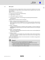
CPC 5100
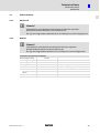
Schaltschrank−PC
Control cabinet PC
l
,
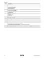
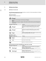
Lesen Sie zuerst diese Anleitung, bevor Sie mit den Arbeiten beginnen!
Beachten Sie die enthaltenen Sicherheitshinweise.
,
Please read these instructions before you start working!
Follow the enclosed safety instructions.
3
4
5
I
1
2
0
0
:
KEYB
MOUSE
VGA
COM1
;
X1
USB
X2
POWER
MIC
LAN
AUDIO
OUT
IN
STANDBY
HD
CTRL
RESET
SLOT A
6
7
USB
B
C
D
8
<
=
>
?
@
E
F
G
9
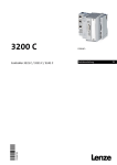
CPC5100−001
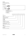
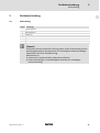
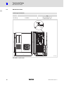
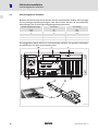
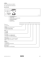
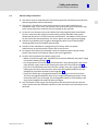
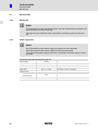
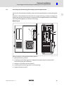
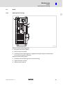
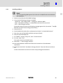
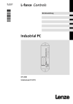
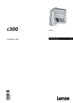
Elemente
Pos.
0
Schaltschrank−PC
1
Netzanschluss 115 ... 230 V AC
2
Netzschalter
3
von links nach rechts:
l Tastatur−Anschluss (PS/2)
l Maus−Anschluss (PS/2)
4
von links nach rechts:
l Analoger Monitoranschluss (VGA)
l Serielle Schnittstelle (COM1)
5
8 x USB−A
2 x Ethernet (RJ45)
von links nach rechts:
l Mikrofon
l Audio Line−Out
l Audio Line−In
6
4
Beschreibung
7
Digitaler Monitoranschluss (DVI auf PCIe−Erweiterungskarte)
8
5 x PCI−Slot
9
PCIe x4−Slot (in x16 socket)
:
Optional belegte Schnittstellen
;
DVD−Laufwerk (Option)
<
Standby−Taster
=
Reset−Taster
>
von oben nach unten:
l Power−LED (leuchtet, wenn Netzspannung anliegt)
l HD−LED (leuchtet bei Festplattenzugriff)
l CTRL−LED (grün: Gehäuselüfter in Betrieb; rot: Gehäuselüfter außer Betrieb)
?
PE−Anschlussschraube (Schutzleiter)
@
Beschriftungsfeld für Anschluss− und Slotbelegung
l
LDCDS−CPC5100 DE/EN 1.1
Gültigkeit
Diese Anleitung ist gültig für
ƒ Schaltschrank−PC CPC 5100
Identifikation
Lenze Digitec Controls GmbH
Grünstr. 36 • D-40667 Meerbusch
P/N
Input
C
UL
R
US LISTED
File E236341
IND. CONT. EQ.
14ZZ
certified
S/N
107AT12345
107AT12345
CS57x0−036
Typbezeichnung
Typschlüssel/Bestellnummer
Technische Daten
Materialnummer (kundenspezifisch)
Seriennummer als Barcode
Herstelleradresse
Zertifizierung
Handzeichen Prüfer
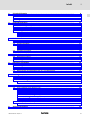
Typenschlüssel
1170
x
x
x
x
xx
x
Gerätetyp
1170 = CPC 5100
Prozessor
5 = Mobile Intelâ Celeron D 3,2 GHz
7 = Intelâ Coreä Duo 1,8 GHz
8 = Intelâ Coreä Duo 2,13 GHz
Arbeitsspeicher
7 = 1024 MB
8 = 2048 MB
9 = 4096 MB
Massenspeicher
1 = Festplatte 1 x 2,5", fest montiert
2 = Festplatte 2 x 2,5", fest montiert
4 = Festplatte 2 x 2,5", im Wechselrahmen
Spannungsversorgung
1 = Netzteil 115 ... 230 V AC, 350 W PFC
2 = Netzteil mit USV 115 ... 230 V AC, 350 W
CD/DVD
0 = ohne
1 = DVD/CD lesen
3 = DVD/CD lesen und schreiben (SATA)
Betriebssystem
0000 = ohne
4100 = Windowsâ XP Multilanguage
LDCDS−CPC5100 DE/EN 1.1
l
5
Dokumenthistorie
Materialnummer
Version
Beschreibung
13251776
1.0
06/2008
TD29
Erstausgabe
.;T/
1.1
08/2008
TD29
Neuen Netzteiltyp ergänzt (betrifft Anschließen/Abklemmen
des Batteriepacks)
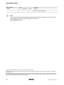
0Abb. 0Tab. 0
I
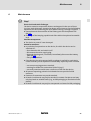
Tipp!
Aktuelle Dokumentationen und Software−Updates zu Lenze Produkten finden Sie im
Internet jeweils im Bereich "Services & Downloads" unter
http://www.Lenze.com
© 2008 Lenze Digitec Controls GmbH, Grünstr. 36, D−40667 Meerbusch
Ohne besondere schriftliche Genehmigung von Lenze Digitec Controls GmbH darf kein Teil dieser Dokumentation vervielfältigt
oder Dritten zugänglich gemacht werden.
Wir haben alle Angaben in dieser Dokumentation mit größter Sorgfalt zusammengestellt und auf Übereinstimmung mit der beschriebenen Hard− und Software geprüft. Trotzdem können wir Abweichungen nicht ganz ausschließen. Wir übernehmen keine
juristische Verantwortung oder Haftung für Schäden, die dadurch eventuell entstehen. Notwendige Korrekturen werden wir in die
nachfolgenden Auflagen einarbeiten.
6
l
LDCDS−CPC5100 DE/EN 1.1
Inhalt
1
2
3
4
5
6
7
8
i
Sicherheitshinweise . . . . . . . . . . . . . . . . . . . . . . . . . . . . . . . . . . . . . . . . . . . . . . . . . . . . . . . .
8
1.1
Definition der verwendeten Hinweise . . . . . . . . . . . . . . . . . . . . . . . . . . . . . . . . . . . .
8
1.2
Allgemeine Sicherheitshinweise . . . . . . . . . . . . . . . . . . . . . . . . . . . . . . . . . . . . . . . .
10
Gerätebeschreibung . . . . . . . . . . . . . . . . . . . . . . . . . . . . . . . . . . . . . . . . . . . . . . . . . . . . . . .
11
2.1
Lieferumfang . . . . . . . . . . . . . . . . . . . . . . . . . . . . . . . . . . . . . . . . . . . . . . . . . . . . . . . .
11
2.2
Bestimmungsgemäße Verwendung . . . . . . . . . . . . . . . . . . . . . . . . . . . . . . . . . . . . .
12
2.3
Grundgerät . . . . . . . . . . . . . . . . . . . . . . . . . . . . . . . . . . . . . . . . . . . . . . . . . . . . . . . . . .
2.3.1
Mainboard . . . . . . . . . . . . . . . . . . . . . . . . . . . . . . . . . . . . . . . . . . . . . . . . . .
2.3.2
Netzteil . . . . . . . . . . . . . . . . . . . . . . . . . . . . . . . . . . . . . . . . . . . . . . . . . . . . .
13
14
15
Technische Daten . . . . . . . . . . . . . . . . . . . . . . . . . . . . . . . . . . . . . . . . . . . . . . . . . . . . . . . . . .
16
3.1
Allgemeine Daten und Einsatzbedingungen
.............................
16
3.2
Elektrische Daten . . . . . . . . . . . . . . . . . . . . . . . . . . . . . . . . . . . . . . . . . . . . . . . . . . . . .
3.2.1
Mainboard . . . . . . . . . . . . . . . . . . . . . . . . . . . . . . . . . . . . . . . . . . . . . . . . . .
3.2.2
Netzteil . . . . . . . . . . . . . . . . . . . . . . . . . . . . . . . . . . . . . . . . . . . . . . . . . . . . .
17
17
17
3.3
Mechanische Daten
.................................................
18
Mechanische Installation . . . . . . . . . . . . . . . . . . . . . . . . . . . . . . . . . . . . . . . . . . . . . . . . . . .
19
4.1
Wichtige Hinweise . . . . . . . . . . . . . . . . . . . . . . . . . . . . . . . . . . . . . . . . . . . . . . . . . . . .
19
4.2
Montageschritte . . . . . . . . . . . . . . . . . . . . . . . . . . . . . . . . . . . . . . . . . . . . . . . . . . . . .
19
Elektrische Installation . . . . . . . . . . . . . . . . . . . . . . . . . . . . . . . . . . . . . . . . . . . . . . . . . . . . .
20
5.1
Wichtige Hinweise . . . . . . . . . . . . . . . . . . . . . . . . . . . . . . . . . . . . . . . . . . . . . . . . . . . .
20
5.2
Erweiterungskarten montieren . . . . . . . . . . . . . . . . . . . . . . . . . . . . . . . . . . . . . . . . .
22
5.3
Batteriepack der optionalen USV an− und abklemmen . . . . . . . . . . . . . . . . . . . . .
24
Wartung . . . . . . . . . . . . . . . . . . . . . . . . . . . . . . . . . . . . . . . . . . . . . . . . . . . . . . . . . . . . . . . . .
26
6.1
Kontrollarbeiten . . . . . . . . . . . . . . . . . . . . . . . . . . . . . . . . . . . . . . . . . . . . . . . . . . . . . .
27
6.2
Instandsetzung . . . . . . . . . . . . . . . . . . . . . . . . . . . . . . . . . . . . . . . . . . . . . . . . . . . . . .
6.2.1
PC−Gehäuse öffnen . . . . . . . . . . . . . . . . . . . . . . . . . . . . . . . . . . . . . . . . . . .
28
28
Anhang . . . . . . . . . . . . . . . . . . . . . . . . . . . . . . . . . . . . . . . . . . . . . . . . . . . . . . . . . . . . . . . . . .
29
7.1
USV−Software Lenze Digitec−USV . . . . . . . . . . . . . . . . . . . . . . . . . . . . . . . . . . . . . . . .
7.1.1
Wichtige Hinweise . . . . . . . . . . . . . . . . . . . . . . . . . . . . . . . . . . . . . . . . . . . .
7.1.2
Software installieren . . . . . . . . . . . . . . . . . . . . . . . . . . . . . . . . . . . . . . . . . .
7.1.3
Software konfigurieren . . . . . . . . . . . . . . . . . . . . . . . . . . . . . . . . . . . . . . . .
7.1.4
Meldung bei Netzausfall . . . . . . . . . . . . . . . . . . . . . . . . . . . . . . . . . . . . . .
7.1.5
Beispiel für ein ausführbares Programm . . . . . . . . . . . . . . . . . . . . . . . . .
29
29
29
31
32
32
7.2
RAID−System . . . . . . . . . . . . . . . . . . . . . . . . . . . . . . . . . . . . . . . . . . . . . . . . . . . . . . . . .
7.2.1
Software installieren . . . . . . . . . . . . . . . . . . . . . . . . . . . . . . . . . . . . . . . . . .
33
34
Stichwortverzeichnis . . . . . . . . . . . . . . . . . . . . . . . . . . . . . . . . . . . . . . . . . . . . . . . . . . . . . . .
35
LDCDS−CPC5100 DE/EN 1.1
l
7
1
Sicherheitshinweise
Definition der verwendeten Hinweise
1
Sicherheitshinweise
1.1
Definition der verwendeten Hinweise
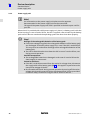
Um auf Gefahren und wichtige Informationen hinzuweisen, werden in dieser Dokumentation folgende Piktogramme und Signalwörter verwendet:
Sicherheitshinweise
Aufbau der Sicherheitshinweise:
}
Gefahr!
(kennzeichnet die Art und die Schwere der Gefahr)
Hinweistext
(beschreibt die Gefahr und gibt Hinweise, wie sie vermieden werden kann)
Piktogramm und Signalwort
Bedeutung
{
Gefahr!
Gefahr von Personenschäden durch gefährliche elektrische Spannung
Hinweis auf eine unmittelbar drohende Gefahr, die den Tod oder
schwere Verletzungen zur Folge haben kann, wenn nicht die entsprechenden Maßnahmen getroffen werden.
Gefahr!
Gefahr von Personenschäden durch eine allgemeine Gefahrenquelle
Hinweis auf eine unmittelbar drohende Gefahr, die den Tod oder
schwere Verletzungen zur Folge haben kann, wenn nicht die entsprechenden Maßnahmen getroffen werden.
Stop!
Gefahr von Sachschäden
Hinweis auf eine mögliche Gefahr, die Sachschäden zur Folge haben kann, wenn nicht die entsprechenden Maßnahmen getroffen
werden.
}
(
Anwendungshinweise
Piktogramm und Signalwort
)
I
,
8
Bedeutung
Hinweis!
Wichtiger Hinweis für die störungsfreie Funktion
Tipp!
Nützlicher Tipp für die einfache Handhabung
Verweis auf andere Dokumentation
l
LDCDS−CPC5100 DE/EN 1.1
Sicherheitshinweise
1
Definition der verwendeten Hinweise
Spezielle Sicherheitshinweise und Anwendungshinweise für UL und UR
Piktogramm und Signalwort
Bedeutung
J
Warnings!
Sicherheitshinweis oder Anwendungshinweis für den Betrieb eines UL−approbierten Geräts in UL−approbierten Anlagen.
Möglicherweise wird das Antriebssystem nicht UL−gerecht betrieben, wenn nicht die entsprechenden Maßnahmen getroffen
werden.
Warnings!
Sicherheitshinweis oder Anwendungshinweis für den Betrieb eines UR−approbierten Geräts in UL−approbierten Anlagen.
Möglicherweise wird das Antriebssystem nicht UL−gerecht betrieben, wenn nicht die entsprechenden Maßnahmen getroffen
werden.
O
LDCDS−CPC5100 DE/EN 1.1
l
9
1
Sicherheitshinweise
Allgemeine Sicherheitshinweise
1.2
10
Allgemeine Sicherheitshinweise
ƒ
Das Gerät darf nur von qualifiziertem Fachpersonal installiert und gewartet werden,
das mit den geltenden nationalen Normen vertraut ist.
ƒ
Das Gerät ist eine Einrichtung der Klasse A. Diese Einrichtung kann im Wohnbereich
Funkstörungen verursachen. In diesem Fall kann vom Betreiber verlangt werden,
angemessene Maßnahmen durchzuführen und dafür aufzukommen.
ƒ
Im Fehlerfall muss das Gerät sofort spannungsfrei geschaltet werden. Dazu
Versorgungsstecker ziehen und ein eventuell vorhandenes Batteriepack
abklemmen. Anschließend ist das Gerät an den Hersteller zu schicken. Die Adresse
finden Sie auf dem Rückumschlag dieser Dokumentation. Bei Rücksendung bitte die
Originalverpackung verwenden!
ƒ
Flachbaugruppen, die durch Kurzschluss oder elektrostatische Entladungen (ESD)
beschädigt werden können, sind vorschriftsmäßig zu handhaben.
ƒ
Das Bios des Mainboards ist werksseitig konfiguriert. Nach einem Update sind
Funktionsstörungen nicht ausgeschlossen. Wenden Sie sich bitte an unseren Service.
ƒ
Zur Entsorgung des Geräts, zerlegen Sie es in seine Einzelteile. Geben Sie Metalle,
Kunststoffe und Leiterplatten in die Wiederverwertung. Beachten Sie die örtlichen
Bestimmungen.
ƒ
Bei IPCs mit einem optionalen USV−Netzteil:
– Vor der Inbetriebnahme des IPCs die Verbindung zwischen Netzteil und
Batteriepack herstellen (¶ 24)!
– Beachten Sie bei allen Arbeiten am IPC: Der IPC ist erst spannungsfrei, wenn das
Netzkabel gezogen ist und die Batteriepack−Zuleitung abgeklemmt ist (¶ 24).
– Wird der PC für längere Zeit vom Netz getrennt, muss die Batteriepack−Zuleitung
abgeklemmt werden, damit die Akkus durch eine mögliche Tiefentladung nicht
beschädigt werden (¶ 24).
– Bei Lagerung verlieren die Akkus über die Zeit Energie. Spätestens nach einem
halben Jahr Lagerung müssen die Akkus daher vollständig durch den IPC geladen
werden. Die Akkus des Batteriepacks dürfen nicht mit externen Ladegeräten
geladen werden.
ƒ
Ein netzseitiger Schutzleiter muss immer an der PE−Anschlussschraube
angeschlossen sein, da andernfalls die in der Konformitätserklärung angegebenen
Normen nicht eingehalten werden.
l
LDCDS−CPC5100 DE/EN 1.1
Gerätebeschreibung
2
Lieferumfang
2
Gerätebeschreibung
2.1
Lieferumfang
Anzahl Bezeichnung
1
Schaltschrank−PC
1
Netzkabel
1
Kleinteilebeutel
1
Treiber−CD
1
Handbuch−CD
1
Testbericht
1
Gerätepass
)
Hinweis!
Überprüfen Sie nach Erhalt der Lieferung sofort, ob der Lieferumfang mit den
Warenbegleitpapieren übereinstimmt. Für nachträglich reklamierte Mängel
übernehmen wir keine Gewährleistung.
Reklamieren Sie
ƒ erkennbare Transportschäden sofort beim Anlieferer.
ƒ erkennbare Mängel / Unvollständigkeit sofort bei der zuständigen
Lenze−Vertretung.
LDCDS−CPC5100 DE/EN 1.1
l
11
2
Gerätebeschreibung
Bestimmungsgemäße Verwendung
2.2
Bestimmungsgemäße Verwendung
Der Schaltschrank−PC wird bestimmungsgemäß verwendet, wenn er ausschließlich zur
Umsetzung von Bedienkonzepten oder zur Darbietung von Informationen in gewöhnlichen industriellen und gewerblichen Bereichen eingesetzt wird. Eine andere oder darüber
hinaus gehende Verwendung ist nicht zulässig.
Eine nichtbestimmungsgemäße Verwendung liegt auch bei einem Gebrauch vor, der verhängnisvolle Risiken oder Gefahren birgt, die ohne Sicherstellung außergewöhnlich hoher
Sicherheitsmaßnahmen zu Tod, Verletzung oder Sachschaden führen können.
Der Schaltschrank−PC darf insbesondere nicht verwendet werden ...
12
ƒ
in privaten Bereichen.
ƒ
in explosionsgefährdeten Bereichen.
ƒ
in Bereichen mit schädlichen Gasen, Ölen, Säuren, Strahlungen usw.
ƒ
zur Wahrnehmung von Sicherheitsfunktionen, zum Beispiel
– in der Flugsicherung / in Flugleitsystemen
– für die Überwachung/Steuerung von Kernreaktionen
– für die Überwachung/Steuerung von Massentransportmitteln
– für die Überwachung/Steuerung von medizinischen Systemen
– für die Überwachung/Steuerung von Waffensystemen
Für die Gewährleistung des Personen− und Sachschutzes müssen übergeordnete Sicherheitssysteme eingesetzt werden!
l
LDCDS−CPC5100 DE/EN 1.1
Gerätebeschreibung
2
Grundgerät
2.3
Grundgerät
Allgemeine Eigenschaften
Ausführung
l
Montage
l
Zum Einbau in Schaltschränke oder Maschinenverkleidungen
Elektrische Versorgung
l
l
Netzteil 115 ... 230 V AC, 350 W
Optional USV (Shutdown−Software und Batteriepack)
Betriebssystem
l
Optional Windowsâ XP Multilanguage
PC−Gehäuse aus chromatiertem Stahlblech mit Lüfter (Überdruckbetrieb)
l Aufkleber aus Polyesterfolie
Rechner−Einheit
ATX−Mainborad KT965/ATXE (Separate Dokumentation auf der Handbuch−CD)
Sockel
l
LGA775
Chipsatz
l
Intel Q965
Grafik
l
Intel® GMA 3000 graphics engine, bis 256 MB DVMT 4.0
Speicher
l
l
4 Speicherbänke, DDR2 DIMM, Dual Channel
512 MB 4 GB (32 Bit Betriebssystem)
Audio
l
Line−in, Line−out, Microphone: MIC1
Verfügbare interne Schnittstellen
l
l
5 x PCI 2.3, 32 Bits, 33 MHz, Kartenlänge max. 210 mm
1 x PCI−Express x16 (belegt durch DVI−Karte) , Kartenlänge max.
210 mm
l 1 x PCI−Express x4, Kartenlänge max. 210 mm
l 6 x Serial ATA−300 IDE Interface
Externe Schnittstellen
LAN
l
2 x 10/100/1000 Mbits/s, Realtek RTL8111B
PS/2
l
l
1 x Maus
1 x Tastatur
USB
l
8 x USB 2.0
COM
l
1 x Seriell (RS232)
Audio
l
1 x Audioblock
– Line−in
– Line−out
– Microphone: MIC1
VGA
l
1 x CRT Support
DVI
l
1 x DVI−D
Massenspeicher
Festplatten
l
l
1 ... 4 SATA−Festplatten, 2,5", 80 GB
Optional Wechselrahmen (für je 2 Festplatten geeignet; ermöglicht die
Hot Plug−Fähigkeit des RAID−Systems
l Optional RAID−Level 0, 1, 5 oder 10 über Software konfigurierbar (interner Wechselrahmen erforderlich)
Prozessor
Typ
Prozessor−Nr.
L2 Cache
Front Side Bus (FSB)
Celeron D 3,2 GHz
352
512 KB
533 MHz
Core 2 Duo 1,8 GHz
E4300
2 MB
800 MHz
Core 2 Duo 2,13
E6400
2 MB
1066 MHz
LDCDS−CPC5100 DE/EN 1.1
l
13
2
Gerätebeschreibung
Grundgerät
Mainboard
2.3.1
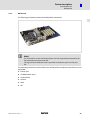
Mainboard
Die folgende Abbildung zeigt das KT965/ATXE−Mainboard.
)
Hinweis!
Informationen zum Mainboard entnehmen Sie bitte der separaten
Mainboard−Dokumentation auf der Handbuch−CD.
Der Typ des eingesetzten Mainboards ist im Gerätepass zu Ihrem IPC genannt.
Folgende Schnittstellen sind im KT965/ATXE−Mainboard−Handbuch beschrieben, werden
aber nicht unterstützt:
14
ƒ
Printer−Port
ƒ
CD−ROM Audio input
ƒ
Audio Header
ƒ
Feature
ƒ
TPM
ƒ
SPI
l
LDCDS−CPC5100 DE/EN 1.1
Gerätebeschreibung
2
Grundgerät
Netzteil
2.3.2
Netzteil
)
Hinweis!
Informationen zum Netzteil entnehmen Sie bitte der separaten
Netzteil−Dokumentation auf der Handbuch−CD.
Der Typ des eingesetzten Netzteils ist im Gerätepass zu Ihrem IPC genannt.
Wenn der IPC mit einem USV−Netzteil ausgestattet ist, befindet sich innerhalb des Gerätegehäuses ein Batteriepack. Bei Netzausfall wird der IPC einige Minuten über das Batteriepack gespeist, bis alle Daten gesichert sind und das Betriebssystem ordentlich heruntergefahren ist.
(
Stop!
Beschädigung der Batteriepack−Akkus
ƒ Bei fehlender Netzspannung werden die Akkus des Batteriepacks über das
IPC−Netzteil entladen − auch bei ausgeschaltetem IPC. Dies kann zu einer
Tiefentladung der Batteriepack−Akkus führen.
ƒ Die USV ist nicht dafür ausgelegt, dass sie den IPC im Normalbetrieb
herunterfährt, sondern nur bei einem Netzausfall.
Mögliche Folgen:
ƒ Die Akkus werden beschädigt. Bei Netzausfall ist die Datensicherheit nicht
gewährleistet.
Schutzmaßnahmen:
ƒ Wenn der IPC für einen längeren Zeitraum vom Netz getrennt werden soll,
Batteriepack−Zuleitung abklemmen (¶ 24). Dies gilt insbesondere für den
Transport oder die Lagerung des IPCs.
ƒ Während des Normalbetriebes den IPC nicht durch Abschalten der
Netzspannung abschalten, so dass die USV den IPC herunterfährt, sondern
immer ordnungsgemäß über den Netzschalter oder über die SPS.
LDCDS−CPC5100 DE/EN 1.1
l
15
3
Technische Daten
Allgemeine Daten und Einsatzbedingungen
3
Technische Daten
3.1
Allgemeine Daten und Einsatzbedingungen
Konformität und Approbation
Konformität
CE
EN 61000 6−2 (4)
EMV−Richtlinie Industriebereich
EN 55022, EN 55024
Einrichtungen der Informationstechnik
Personenschutz und Geräteschutz
Schutzart
IP20
Schutzklasse
1
Montagebedingungen
Einbauort
Schaltschrank
Einbaulage
vertikal mit Netzteil−Lüfter oben oder
horizontal mit Geräte−Lüfter oben
Umgebungsbedingungen
Klimatisch
Lagerung
ohne USV
−10 ... +60 °C
mit USV
−10 ... +40 °C
Transport
ohne USV
−10 ... +60 °C
mit USV
−10 ... +40 °C
Betrieb
abhängig von der Ausstattung (^ 16)
Relative Luftfeuchte
10 ... 90 %, nicht kondensierend
Aufstellhöhe
)
< 3000 m üNN
Hinweis!
Die Ausfallwahrscheinlichkeit eines elektronischen Bauteils wächst mit der
Umgebungstemperatur, der das Bauteil ausgesetzt ist. In Hinblick auf
Betriebsfähigkeit und Zuverlässigkeit ist der Gerätekühlung also besondere
Aufmerksamkeit zu schenken. Grundsätzlich sollte in jeder Applikation mit
Sorgfalt darauf geachtet werden, die Erwärmung des Gerätes so gering wie
möglich zu halten.
Zulässige Umgebungstemperaturen
Ohne USV
£40 W Zusatzbelastung durch
PCI−Erweiterungen
£ 100 W Zusatzbelastung durch
PCI−Erweiterungen
[°C]
Grundgerät mit
Mobile Intelâ Celeron D 3,2 GHz
Intelâ Coreä 2 Duo 1,8 GHz
Mit USV
5 ... 45
[°C]
5 ... 40
5 ... 35
Intelâ Coreä 2 Duo 2,13 GHz
16
l
LDCDS−CPC5100 DE/EN 1.1
Technische Daten
3
Elektrische Daten
Mainboard
3.2
Elektrische Daten
3.2.1
Mainboard
)
Hinweis!
Informationen zum Mainboard entnehmen Sie bitte der separaten
Mainboard−Dokumentation auf der Handbuch−CD.
Der Typ des eingesetzten Mainboards ist im Gerätepass zu Ihrem IPC genannt.
3.2.2
Netzteil
)
Hinweis!
Informationen zum Netzteil entnehmen Sie bitte der separaten
Netzteil−Dokumentation auf der Handbuch−CD.
Der Typ des eingesetzten Netzteils ist im Gerätepass zu Ihrem IPC genannt.
Batteriepack des optionalen USV−Netzteils
Bemessungsspannung
24 V DC
Bemessungsleistung
100 VA
Bemessungskapazität
2,0 Ah
Sicherung
20 A
Pufferzeit
max. 3 ... 10 min
ATOâ−Sicherung (Messerkontakt)
je nach PC−Ausstattung
Ladezeit
bei Erstinbetriebnahme
danach
LDCDS−CPC5100 DE/EN 1.1
24 h
max. 10 ... 15 h
l
17
3
Technische Daten
Mechanische Daten
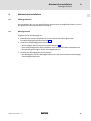
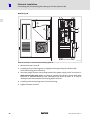
3.3
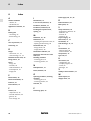
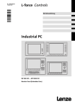
Mechanische Daten
Ausführungen und Gewichte
Gehäuse
Masse
[kg]
CPC 5100
ohne Batteriepack: 12,2
mit Batteriepack: 15,0
Stahlblech
9
12
Ø6.5
VGA
COM1
min. Abstand für Luftansaugung
MOUSE
X1
467
X2
438
408
USB
POWER
USB
MIC
LAN
AUDIO
OUT
IN
STANDBY
HD
CTRL
RESET
min. distance for air inlet
I
KEYB
0
Ø15
SLOT A
B
Luft
air
C
D
E
F
316.5
11.5
G
11
32
111
176
10
40
CPC5100−002
Alle Maße in Millimeter.
18
l
LDCDS−CPC5100 DE/EN 1.1
Mechanische Installation
4
Wichtige Hinweise
4
Mechanische Installation
4.1
Wichtige Hinweise
Die Installation darf nur von qualifiziertem Fachpersonal durchgeführt werden, das mit
den geltenden nationalen Normen vertraut ist.
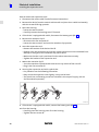
4.2
Montageschritte
So gehen Sie bei der Montage vor:
1. Kontrollieren, dass der Einbauort die in den Technischen Daten genannten
Einsatzbedingungen gewährleistet (¶ 16).
2. Schaltschrank−Montageplatte vorbereiten.
– Abmessungen und Einbaufreiräume beachten (¶ 18).
– Zum Laden/Entladen des DVD−Laufwerks muss ausreichend Platz vorhanden sein.
– Die Belüftungsöffnungen dürfen nicht abgedeckt sein.
3. Gerät an der Montageplatte festschrauben.
– Der Montageort und das Montagematerial muss die mechanischen Verbindungen
dauerhaft gewährleisten.
LDCDS−CPC5100 DE/EN 1.1
l
19
5
Elektrische Installation
Wichtige Hinweise
5
Elektrische Installation
5.1
Wichtige Hinweise
Die Installation darf nur von qualifiziertem Fachpersonal durchgeführt werden, das mit
den geltenden nationalen Normen vertraut ist.
(
Stop!
Kurzschluss und statische Entladungen
Das Gerät enthält Bauelemente, die bei Kurzschluss oder statischer Entladung
gefährdet sind. Eine besondere Gefahr besteht, weil für die folgenden Arbeiten
das Gerätegehäuse bei anliegender Spannung geöffnet werden muss:
ƒ Anklemmen und Abklemmen des Batteriepacks zur optionalen USV (¶ 24).
ƒ Austausch der hotplug−fähigen Festplatten im optionalen Wechselrahmen.
Mögliche Folgen:
ƒ Das Gerät oder Teile davon werden zerstört.
Schutzmaßnahmen:
ƒ Vor allen Arbeiten am Gerät, für die das Gerät ausgeschaltet sein kann:
– IPC herunterfahren und ausschalten.
– Netzanschlussstecker ziehen.
– Gehäuse öffnen und, falls vorhanden, sofort Batteriepack abklemmen
(¶ 24).
– Arbeiten durchführen.
ƒ Wenn das Gehäuse bei anliegender Spannung geöffnet werden muss, mit
besonderer Vorsicht vorgehen und alle Arbeiten umgehend durchführen.
Insbesondere sicherstellen, dass ...
– keine stromführenden Teile berührt werden.
– drehende Lüfterflügel nicht berührt werden (Verletzungsgefahr!).
– keine Kleinteile, die einen Kurzschluss verursachen könnten, in das Gerät
fallen.
ƒ Alle Personen, die Flachbaugruppen handhaben, müssen ESD−Maßnahmen
berücksichtigen.
ƒ Kontakte von Steckverbindern dürfen nicht berührt werden.
ƒ Flachbaugruppen dürfen nur an kontaktfreien Stellen angefasst werden und
nur auf geeigneten Unterlagen abgelegt werden (z. B. auf ESD−Verpackung
oder leitfähigem Schaumstoff).
ƒ Flachbaugruppen dürfen nur in ESD−Verpackungen transportiert und
gelagert werden.
20
l
LDCDS−CPC5100 DE/EN 1.1
Elektrische Installation
5
Wichtige Hinweise
( Stop!
Kein Geräteschutz für zu hohe Eingangsspannung
Der Spannungseingang ist intern nicht abgesichert.
Mögliche Folgen:
ƒ Zerstörung des Gerätes bei zu hoher Eingangsspannung.
Schutzmaßnahmen:
ƒ Beachten Sie die maximal zulässige Eingangsspannung.
ƒ Sichern Sie das Gerät eingangsseitig fachgerecht gegen
Spannungsschwankungen und −spitzen ab.
( Stop!
Einschränkungen der EMV−Verträglichkeit möglich
Die in der Konformitätserklärung angegebenen Normen werden nicht
eingehalten, wenn der IPC nicht ordnungsgemäß installiert ist.
Mögliche Folgen:
ƒ Andere elektrische Geräte werden in Ihrer Funktion beeinträchtigt.
Schutzmaßnahmen:
ƒ Während des Betriebes muss der netzseitige Schutzleiter immer an der
PE−Anschlussschraube angeschlossen sein.
LDCDS−CPC5100 DE/EN 1.1
l
21
5
Elektrische Installation
Erweiterungskarten montieren
5.2
Erweiterungskarten montieren
Beachten Sie beim Einbau von PCI−Karten, dass die nachstehenden Ströme und Leistungen
für die jeweiligen Netzteilspannungen nicht überschritten werden, da dies andernfalls
Auswirkungen auf die zulässigen Umgebungstemperaturen hat.
Netzteil−Ausgangsspannungen
max. Strom
zul. Leistung
[V DC]
[A]
[W]
+3.3
15
< 50
+5
14
< 75
+3.3 und +5
33
−
+12
8
< 100
+ 3,3 und + 5 und + 12
−
< 100
Die angegebenen Werte können je nach Netzteiltyp variieren. Für genauere Informationen wenden Sie sich bitte an den Lenze−Service.
1
2
1
C
D
E
F
G
HD
CTRL
RESET
B
5
MIC
LAN
AUDIO
IN
OUT
I
0
USB
COM1
VGA
USB
MOUSE
0
KEYB
POWER
X2
X1
STANDBY
SLOT A
3
6
5
4
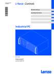
CPC5100−004
22
l
LDCDS−CPC5100 DE/EN 1.1
Elektrische Installation
5
Erweiterungskarten montieren
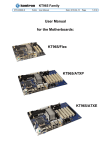
So montieren Sie Erweiterungskarten:
1. Netzkabel 0 und alle externen Anschlüsse ziehen.
2. Gerät von der Schaltschrankwand nehmen und waagerecht, mit den Schrauben 1
nach oben, auf einen Tisch legen.
3. Gehäuse öffnen:
– Zwei Schrauben 1 lösen.
– Gehäusedeckel 2 vorsichtig nach vorne abziehen.
4. Wenn das Gerät mit einer USV ausgestattet ist, Batteriepack abklemmen (¶ 24).
5. Niederhalter 3 entfernen:
– Lüfterstecker 4 abziehen.
– Zwei Schrauben 5 lösen und den Niederhalter nach oben schwenken.
6. Erweiterungskarte einsetzen:
– Bracket des gewünschten Slots 6 entfernen.
– Erweiterungskarte von oben mit leichtem Druck in die Buchsenleiste auf dem
Mainboard drücken. Das Mainboard darf sich dabei nicht biegen!
– Kontrollieren, dass die Karte korrekt in der Buchsenleiste sitzt.
– Bracket der Erweiterungskarte festschrauben.
7. Niederhalter 3 montieren:
– Niederhalter nach unten schwenken und mit Schraube 5 fixieren.
– Lüfterstecker 4 stecken.
8. Erweiterungskarte mit Kunststoffriegel fixieren
– Vorgehensweise siehe nachfolgende Abbildung.
– Die Erweiterungskarte nur leicht fixieren; sie darf sich nicht biegen!
– Kunststoffriegel und Fixierschrauben sind im Lieferumfang enthalten, können
aber auch separat bestellt werden.
CPC5100−005
9. Wenn das Gerät mit einer USV ausgestattet ist, Batteriepack anklemmen (¶ 24).
10. Gehäuse schließen:
– Gehäusedeckel 2 vorsichtig auf das Gehäuse setzen.
– Zwei Schrauben 1 festziehen.
LDCDS−CPC5100 DE/EN 1.1
l
23
5
Elektrische Installation
Batteriepack der optionalen USV an− und abklemmen
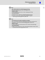
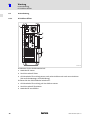
5.3
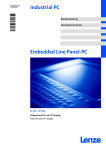
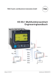
Batteriepack der optionalen USV an− und abklemmen
Für die USV−Funktionalität muss das Batteriepack vor der Inbetriebnahme des IPCs angeklemmt werden.
Wenn der IPC eine längere Zeit vom Netz getrennt ist (z. B. Transport, Lagerung), muss das
Batteriepack abgeklemmt werden, da andernfalls die Akkus des Batteriepacks durch eine
Tiefentladung beschädigt werden können.
I
0
0
Netzteil Typ A
1
3
KEYB
MOUSE
VGA
COM1
2
X1
USB
X2
POWER
USB
MIC
LAN
AUDIO
OUT
IN
STANDBY
HD
CTRL
RESET
SLOT A
B
C
1
D
E
F
G
CPC5100−009
So klemmen Sie das Batteriepack 0 an bzw. ab:
1. Zwei Schrauben 1 enfernen.
2. Gehäusedeckel 2 vorsichtig etwas nach rechts drücken und nach vorne abziehen
(bei vertikale Montage, siehe Abbildung).
3. Steckverbinder 3 zusammenstecken bzw. trennen.
4. Gehäusedeckel 2 vorsichtig auf das Gehäuse setzen.
5. Zwei Schrauben 1 festziehen.
24
l
LDCDS−CPC5100 DE/EN 1.1
Elektrische Installation
5
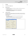
Batteriepack der optionalen USV an− und abklemmen
I
4
3
0
0
Netzteil Typ B
1
KEYB
MOUSE
VGA
COM1
2
X1
USB
X2
POWER
USB
MIC
LAN
AUDIO
OUT
IN
STANDBY
HD
CTRL
RESET
SLOT A
B
C
1
D
E
F
G
CPC5100−010
So klemmen Sie das Batteriepack 0 an bzw. ab:
1. Zwei Schrauben 1 enfernen.
2. Gehäusedeckel 2 vorsichtig etwas nach rechts drücken und nach vorne abziehen
(bei vertikale Montage, siehe Abbildung).
3. Stecker 3 in die Anschlussbuchse des Netzteils 4 stecken bzw. davon abziehen.
Nach dem Abziehen des Steckers: Stellen Sie sicher, dass seine Kontakte nicht mit anderen elektrischen oder elektrisch−leitenden Teilen im Berührung kommen können.
Andernfalls könnte das Gerät oder Teile davon beschädigt werden. Wir empfehlen, den
Stecker mit einem Kabelbinder zu fixieren.
4. Gehäusedeckel 2 vorsichtig auf das Gehäuse setzen.
5. Zwei Schrauben 1 festziehen.
LDCDS−CPC5100 DE/EN 1.1
l
25
6
Wartung
6
Wartung
(
Stop!
Kurzschluss und statische Entladungen
Das Gerät enthält Bauelemente, die bei Kurzschluss oder statischer Entladung
gefährdet sind. Eine besondere Gefahr besteht, weil für die folgenden Arbeiten
das Gerätegehäuse bei anliegender Spannung geöffnet werden muss:
ƒ Anklemmen und Abklemmen des Batteriepacks zur optionalen USV (¶ 24).
ƒ Austausch der hotplug−fähigen Festplatten im optionalen Wechselrahmen.
Mögliche Folgen:
ƒ Das Gerät oder Teile davon werden zerstört.
Schutzmaßnahmen:
ƒ Vor allen Arbeiten am Gerät, für die das Gerät ausgeschaltet sein kann:
– IPC herunterfahren und ausschalten.
– Netzanschlussstecker ziehen.
– Gehäuse öffnen und, falls vorhanden, sofort Batteriepack abklemmen
(¶ 24).
– Arbeiten durchführen.
ƒ Wenn das Gehäuse bei anliegender Spannung geöffnet werden muss, mit
besonderer Vorsicht vorgehen und alle Arbeiten umgehend durchführen.
Insbesondere sicherstellen, dass ...
– keine stromführenden Teile berührt werden.
– drehende Lüfterflügel nicht berührt werden (Verletzungsgefahr!).
– keine Kleinteile, die einen Kurzschluss verursachen könnten, in das Gerät
fallen.
ƒ Alle Personen, die Flachbaugruppen handhaben, müssen ESD−Maßnahmen
berücksichtigen.
ƒ Kontakte von Steckverbindern dürfen nicht berührt werden.
ƒ Flachbaugruppen dürfen nur an kontaktfreien Stellen angefasst werden und
nur auf geeigneten Unterlagen abgelegt werden (z. B. auf ESD−Verpackung
oder leitfähigem Schaumstoff).
ƒ Flachbaugruppen dürfen nur in ESD−Verpackungen transportiert und
gelagert werden.
26
l
LDCDS−CPC5100 DE/EN 1.1
Wartung
6
Kontrollarbeiten
6.1
Kontrollarbeiten
Das Gerät ist wartungsfrei. Trotzdem müssen Sie in regelmäßigen und unter Berücksichtigung der Umgebungsbedingungen ausreichend kurzen Intervallen eine Sichtprüfung
durchführen.
Kontrollieren Sie:
ƒ
Entspricht die Umgebung des Gerätes noch den in den Technischen Daten
genannten Einsatzbedingungen?
ƒ
Behindert kein Staub oder Schmutz die Wärmeabfuhr des Gerätes?
ƒ
Sind die mechanischen und elektrischen Verbindungen in Ordnung?
ƒ
Lassen sich die Lüfter drehen?
LDCDS−CPC5100 DE/EN 1.1
l
27
6
Wartung
Instandsetzung
PC−Gehäuse öffnen
6.2
Instandsetzung
6.2.1
PC−Gehäuse öffnen
I
0
0
1
KEYB
MOUSE
VGA
COM1
2
X1
USB
X2
POWER
USB
MIC
LAN
AUDIO
OUT
IN
STANDBY
HD
CTRL
RESET
SLOT A
B
C
1
D
E
F
G
CPC5100−003
So nehmen Sie den Gehäusedeckel ab:
1. Netzkabel 0 ziehen.
2. Zwei Schrauben 1 lösen.
3. Gehäusedeckel 2 vorsichtig etwas nach rechts drücken und nach vorne abziehen
(bei vertikale Montage, siehe Abbildung).
So setzen Sie den Gehäusedeckel wieder auf:
1. Gehäusedeckel 2 vorsichtig auf das Gehäuse setzen.
2. Zwei Schrauben 1 festziehen.
3. Netzkabel 0 anschließen.
28
l
LDCDS−CPC5100 DE/EN 1.1
Anhang
7
USV−Software Lenze Digitec−USV
Wichtige Hinweise
7
Anhang
7.1
USV−Software Lenze Digitec−USV
7.1.1
Wichtige Hinweise
7.1.2
ƒ
Die optionale USV wird über die Software Lenze−Digitec−USV−Software Version 3.3.1
oder höher angesteuert.
ƒ
Bei Netzspannungsausfall kann die USV den IPC nur ordnungsgemäß
herunterfahren, wenn zum Beenden der laufenden Programme keine
Benutzereingaben erforderlich sind.
Software installieren
Die Software ist werksseitig vorinstalliert, wenn Sie die Option ˜mit USV˜ bei der Bestellung angegeben haben und Sie das Betriebssystem auf einem Speichermedium von Lenze
Digitec bezogen haben.
In anderen Fällen:
1. Setup−Programm auf der Programm−CD starten und den Anweisungen des
Setup−Assistenten folgen.
Pfad auf CD: x:\tools_drivers\ups_usv\usv_software\usv_331\setup.exe
2. Nach dem Kopieren der Programmdateien, Software konfigurieren:
LDCDS−CPC5100 DE/EN 1.1
l
29
7
Anhang
USV−Software Lenze Digitec−USV
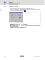
Software installieren
USV: Wählen Sie aus der Liste den Typ "MPS1068/AUP−X−300−V4"
Programm ausführen: Während die USV−Software bei Netzausfall die Sekunden bis
zum Shutdown herunterzählt, kann ein externes Programm gestartet werden. Tragen
Sie hier das Programm ein (¶ 32).
Port: Die USV ist werksseitig an COM2 angeschlossen.
Wenn Sie einen festen COM−Port einstellen, wird automatisch die Standardadresse
übernommen. Falls Sie den Eintrag "Benutzerdefiniert" auswählen, können Sie über
die Pfeile neben dem Adressfeld die Adresse im Bereich von 0100h bis 03F8h frei einstellen. Änderungen werden erst nach einem Neustart des PCs übernommen.
Shutdown: Bestimmt die Art, wie das Betriebssystem heruntergefahren wird. Standardmäßig wird die Option "Shutdown" eingestellt.
Die Option "Fast Shutdown" definiert einen erzwungenen Shutdown (Forced Shutdown) des Betriebssystems. Alle laufenden Programme werden dabei ohne Berücksichtigung eventueller Rückmeldungen beendet und das System wird heruntergefahren. Achtung: Diese Einstellung kann zu Datenverlust bei den laufenden
Anwendungen führen!
Zeit bis zum Shutdown: Hier können Sie die Zeitspanne vom Stromausfall bis zum Herunterfahren des Systems in 15−Sekunden−Schritten einstellen. Maximal 2 Minuten
können eingestellt werden. Falls das Kästchen "warten bis zum Battery−Low−Signal"
aktiviert ist, kann der Schieberegler nicht verschoben werden. Bei dieser Einstellung
wird der Rechner so lange wie möglich von der USV gepuffert.
Zeit bis zur Benachrichtigung: Hier können Sie eine Zeit von 0 bis 10 Sekunden einstellen, die zwischen dem Netzausfall und dem Erscheinen des Meldungsfenster vergehen
soll. Dies kann hilfreich sein, falls kurzzeitige Netzausfälle auftreten und dann nicht sofort ein Meldungsfenster erscheinen soll.
3. Auf Weiter klicken.
Das Programm versucht nun die USV zu verifizieren. Sollte die USV unter dem angewählten Port nicht erkannt werden, überprüfen Sie bitte die externe RS232−Kabelverbindung vom Rechner zur USV und stellen Sie sicher, dass die USV tatsächlich mit dem
gewählten Port verbunden ist. Das Setup−Programm ruft dann erneut den Dialog für
die Einstellungen auf.
Um die USV−Software zu aktivieren, muss Windows neu gestartet werden.
4. Wählen Sie "Windows neu starten" und klicken Sie auf "OK".
Die USV−Software ist damit installiert. Nach jedem Starten von Windows wird die USV
automatisch aktiviert.
30
l
LDCDS−CPC5100 DE/EN 1.1
Anhang
7
USV−Software Lenze Digitec−USV
Software konfigurieren
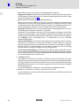
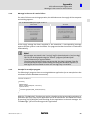
7.1.3
Software konfigurieren
1. Doppelklick auf dem USV−Icon im Infobereich der Windows−Taskleiste ausführen.
Der Dialog "USV" wird geöffnet. Über die Register dieses Dialogs haben Sie Zugriff auf
den aktuellen Status der USV sowie auf alle Einstellungen (¶ 29).
Power: Status der USV ("OK" oder "Fail").
Batterie: Status der Batterie ("Voll" oder "Wird entladen").
Port: COM−Port des PCs ("1", "2", "3", "4" oder "Benutzerdefiniert). Änderungen
werden erst nach einem Neustart des PCs übernommen.
Zähler: Die Zeit in [s] bis der PC heruntergefahren wird.
LDCDS−CPC5100 DE/EN 1.1
l
31
7
Anhang
USV−Software Lenze Digitec−USV
Meldung bei Netzausfall
7.1.4
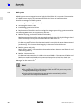
Meldung bei Netzausfall
Wenn während des Betriebes das Netz ausfällt, übernimmt die USV die Versorgung des
Rechners und ein Dialog wird eingeblendet:
Wenn in den Einstellungen das Kontrollfeld Warten bis zum battery−low−Signal ...
demarkiert ist:
markiert ist:
Sollte zwischenzeitlich die Versorgungsspannung wieder anliegen, wird dieses gemeldet,
und das System wird nicht heruntergefahren. Das zuletzt aktive Programm ist automatisch wieder aktiviert.
)
Hinweis!
Alle Meldungen werden in der Protokolldatei "usv.log" gespeichert
(Standardpfad c:/usv/usv.log), die mit dem Programm "Viewer" (Standardpfad
c:/usv/viewer.exe) oder einem beliebigen Texteditor angezeigt werden kann.
Damit die Protokolldatei nicht zu lang wird, werden deren Daten gelöscht,
sobald die Dateigröße 64 KB übersteigt. Wenn Sie die Protokolldatei über den
Windows−Explorer® löschen, wird diese neu angelegt, sobald ein neuer
Protokolleintrag vorliegt.
7.1.5
Beispiel für ein ausführbares Programm
Das folgende C−Programm schließt eine laufende Windows−Applikation (als Beispiel hier
der Taschenrechner aus dem Windows−Zubehör):
#include <stdio.h>
#include <windows.h>
void main()
{
HANDLE hWnd;
hWnd=::FindWindow(NULL,"Rechner");
if (hWnd!=NULL)
{
::PostMessage(hWnd,WM_CLOSE,NULL,NULL);
}
}
Mit der Funktion "FindWindow" erhalten Sie ein Handle auf das entsprechende Fenster.
Als Parameter muss der Klassenname der Applikation übergeben werden. Diesen Namen
erhalten Sie, wenn Sie [Strg]+[Alt]+[Entf] drücken und im Task−Manager nach der Applikation suchen. Dieser Applikation senden Sie durch "PostMessage" eine Nachricht.
32
l
LDCDS−CPC5100 DE/EN 1.1
Anhang
7
RAID−System
7.2
RAID−System
Ein RAID−System dient zur Organisation mehrerer physischer Festplatten eines Computers. Der Betrieb eines RAID−Systems setzt mindestens zwei Festplatten voraus, die einen
Verbund bilden.
Mögliche Vorteile eines RAID−Systems:
ƒ
Erhöhung der Ausfallsicherheit (Redundanz)
ƒ
Steigerung der Transferrate
ƒ
Aufbau großer logischer Laufwerke
ƒ
Austausch von Festplatten und Erhöhung der Speicherkapazität während des
Systembetriebs
Folgende RAID−Level werden vom IPC unterstützt:
ƒ
RAID 0 − Striping, Beschleunigung ohne Redundanz
RAID 0 erhöht die Transferrate gegenüber einer einzelnen Festplatte, indem die beteiligten Festplatten (mindestens 2) in zusammenhängende Blöcke gleicher Größe aufgeteilt werden.
ƒ
RAID 1 − Spiegelung
Ein RAID−1−System besteht aus mindestens zwei Festplatten, auf denen die gleichen
Daten abgelegt sind (Redundanz). Dies erhöht die Datensicherheit bei einem Festplattenfehler.
ƒ
RAID 5 − Leistung und Parität
RAID 5 bietet sowohl gesteigerten Datendurchsatz beim Lesen von Daten (RAID 0) als
auch Redundanz (RAID 1).
ƒ
RAID10 − Verbund
Ein RAID−10−Verbund ist ein RAID 0 über mehrere RAID 1. Dabei werden die beiden Eigenschaften von RAID 0 und RAID 1 kombiniert. Ein RAID−10−Verbund benötigt mindestens vier Festplatten.
Weitere Informationen entnehmen Sie der Dokumentation "Intel Matrix Storage Mananger" auf der Handbuch−CD.
)
Hinweis!
Beachten Sie beim Einsatz eines RAID−Systems Folgendes:
ƒ Die Zuordnung der Wechselfestplatten zu den SATA−Ports darf nicht
geändert werden (siehe Beschriftung der Ports).
ƒ Bei einem Festplattenwechsel während des Betriebs darf der Niederhalter
der Erweiterungskarten nicht entfernt werden.
LDCDS−CPC5100 DE/EN 1.1
l
33
7
Anhang
RAID−System
Software installieren
7.2.1
Software installieren
)
Hinweis!
Das entsprechende RAID−System muss vor der Windows XP−Installation im
BIOS eingestellt werden.
1. IPC einschalten und BIOS−Einstellungen aufrufen.
2. Folgende Einstellungen im BIOS vornehmen:
– Advanced −> IDE Configuration −> Configure S−ATA#1 as RAID
– Boot −> Boot Device Priority −> 1st Boot Device ["actual CD−rom drive"]
– Exit −> Save Changes and Exit
Während des Bootens erscheint für 1/2 Sekunde folgende Meldung: ""Intel(R) RAID for
Serial ATA − Raid Configuration Utility"
3. [Strg] + [I] drücken.
4. Überprüfen, ob die SATA−Platten erkannt werden und "1 Create RAID Volume"
auswählen.
5. Name der RAID−Installation eingeben und [Enter] drücken.
6. Gewünschten RAID Level wählen.
7. Bei "RAID0": "Strip Size" aktivieren, dann "Create Volume".
8. Zum Beenden ˜Exit˜ auswählen.
Das System kehr in das BIOS−Menü zurück.
9. Exit − > "Save Changes and Exit" wählen.
10. LDC−Windows−XP−DVD einlegen und den Anweisungen der Windows−Installation
folgen.
11. Abschließend die "Intel Matrix Storage Console" von der LDC−Tool− und Treiber−CD
installieren.
Weitere Informationen entnehmen Sie der zugehörigen Dokumentation.
34
l
LDCDS−CPC5100 DE/EN 1.1
Stichwortverzeichnis
8
8
Stichwortverzeichnis
A
Aufstellhöhe, 16
Ausführung, Gerät, 18
B
Batteriepack
− abklemmen, 24
− anklemmen, 24
Bestimmungsgemäße Verwendung,
12
Gerät
− Ausführung, 18
− Entsorgung, 10
− Funkstörungen, 10
− Gewicht, 18
− Übersicht, 4
R
Gewicht, Gerät, 18
Schutzklasse, 16
Gültigkeit der Anleitung, 5
Sicherheitshinweise, 8
− allgemeine, 10
− Bestimmungsgemäße Verwendung,
12
− Definition, 8
− Gestaltung, 8
H
Hinweise, Definiton, 8
D
I
Definition der verwendeten Hinweise,
8
Identifikation, 5
Installation, elektrische, 20
Installation, mechanische, 19
RAID−System, 33
S
Schutzart, 16
Statische Entladung, 20 , 26
T
Eigenschaften, 13
K
Technische Daten, 16
− Elektrische Daten, 17
− Mechanische Daten, 18
− allgemeine, 13
− Externe Schnittstellen, 13
− Massenspeicher, 13
− Rechner−Einheit, 13
Konformität, 16
Temperaturen, 16
Kurzschluss, 20 , 26
Typenschildangaben, 5
E
Einsatzbedingungen,
Montagebedingungen
Typenschlüssel, 5
L
Lieferumfang, 11
U
− Einbaulage, 16
− Einbauort, 16
M
Übersicht, 4
Elektrische Daten, 17
Mainboard, 14 , 17
Elektrische Installation, 20
Mechanische Daten, 18
− Ausführung, Gerät, 18
− Gewicht, Gerät, 18
Entsorgung, 10
Erweiterungskarten montieren,
öffnen, 22
Mechanische Installation, 19
Meldungen bei Netzausfall, 32
F
Fehlerfall, Verhalten, 10
Montagebedingungen
− Einbaulage, 16
− Einbauort, 16
Funkstörungen, 10
Gefahr
− Kurzschluss, 20 , 26
− Statische Entladung, 20 , 26
LDCDS−CPC5100 DE/EN 1.1
USV−Software, 29
− Beispielprogramm, 32
− installieren, 29
− konfigurieren, 31
− Meldungen, 32
V
Verhalten im Fehlerfall, 10
N
G
Umgebungsbedingungen
− Aufstellhöhe, 16
− klimatisch, 16
Netzteil, 15 , 17
W
P
Wartung, 26
− Erweiterungskarten montieren, 22
− PC−Gehäuse öffnen, 28
PC−Gehäuse, öffnen, 28
l
35
Elements
Pos.
0
Control cabinet PC
1
Mains connection 115 ... 230 V AC
2
Mains switch
3
From left to right:
l Keyboard connection (PS/2)
l Mouse connection (PS/2)
4
From left to right:
l Analog monitor connection (VGA)
l Serial interface (COM1)
5
8 x USB−A
2 x Ethernet (RJ45)
From left to right:
l Microphone
l Audio line−out
l Audio line−in
6
36
Description
7
Digital monitor connection (DVI on PCIe expansion card)
8
5 x PCI slot
9
PCIe x4 slot (in x16 socket)
:
Optionally assigned interfaces
;
DVD drive (option)
<
Stand−by pushbutton
=
Reset pushbutton
>
From the top to the bottom:
l Power LED (is lit if mains voltage is applied)
l HD−LED (is lit if the hard disk is accessed)
l CTRL−LED (green: housing fan in operation; red: housing fan out of service)
?
PE terminal screw (protective conductor)
@
Labelling field for the terminal and slot assignment
l
LDCDS−CPC5100 DE/EN 1.1
Validity
These instructions are valid for
ƒ CPC 5100 control cabinet PC
Identification
Lenze Digitec Controls GmbH
Grünstr. 36 • D-40667 Meerbusch
C
P/N
Input
UL
R
US LISTED
File E236341
IND. CONT. EQ.
14ZZ
certified
S/N
107AT12345
107AT12345
CS57x0−036
Type designation
Type key/order number
Technical data
Material number (customer−specific)
Serial number as bar code
Manufacturer address
Certification
Sign of inspector
Type code
1170
x
x
x
x
xx
x
Device type
1170 = CPC 5100
Processor
5 = Mobile Intelâ Celeron D 3.2 GHz
7 = Intelâ Coreä Duo 1.8 GHz
8 = Intelâ Coreä Duo 2.13 GHz
RAM
7 = 1024 MB
8 = 2048 MB
9 = 4096 MB
Mass storage
1 = hard disk 1 x 2.5", fixedly mounted
2 = hard disk 2 x 2.5", fixedly mounted
4 = hard disk 2 x 2.5", within removable rack
Voltage supply
1 = power supply unit 115 ... 230 V AC, 350 W PFC
2 = power supply unit with UPS 115 ... 230 V AC,
350 W
CD/DVD
0 = without
1 = DVD/CD read
3 = DVD/CD read and write (SATA)
Operating system
0000 = without
4100 = Windowsâ XP Multilanguage
LDCDS−CPC5100 DE/EN 1.1
l
37
Document history
Material number
Version
Description
13251776
1.0
06/2008
TD29
First edition
.;T/
1.1
08/2008
TD29
New power supply unit type added (refers to connection/disconnection of the battery pack)
0Fig. 0Tab. 0
I
Tip!
Current documentation and software updates concerning Lenze products can be found on
the Internet in the "Services & Downloads" area under
http://www.Lenze.com
© 2008 Lenze Digitec Controls GmbH, Grünstr. 36, D−40667 Meerbusch
No part of this documentation may be reproduced or made accessible to third parties without written consent by Lenze Digitec
Controls GmbH.
All information given in this documentation has been selected carefully and complies with the hardware and software described.
Nevertheless, discrepancies cannot be ruled out. We do not take any responsibility or liability for any damage that may occur. Necessary corrections will be included in subsequent editions.
38
l
LDCDS−CPC5100 DE/EN 1.1
Contents
1
2
3
4
5
6
7
8
i
Safety instructions . . . . . . . . . . . . . . . . . . . . . . . . . . . . . . . . . . . . . . . . . . . . . . . . . . . . . . . . .
40
1.1
Definition of notes used . . . . . . . . . . . . . . . . . . . . . . . . . . . . . . . . . . . . . . . . . . . . . . .
40
1.2
General safety instructions . . . . . . . . . . . . . . . . . . . . . . . . . . . . . . . . . . . . . . . . . . . . .
41
Device description . . . . . . . . . . . . . . . . . . . . . . . . . . . . . . . . . . . . . . . . . . . . . . . . . . . . . . . .
42
2.1
Scope of supply . . . . . . . . . . . . . . . . . . . . . . . . . . . . . . . . . . . . . . . . . . . . . . . . . . . . . .
42
2.2
Application as directed . . . . . . . . . . . . . . . . . . . . . . . . . . . . . . . . . . . . . . . . . . . . . . . .
43
2.3
Standard device . . . . . . . . . . . . . . . . . . . . . . . . . . . . . . . . . . . . . . . . . . . . . . . . . . . . . .
2.3.1
Mainboard . . . . . . . . . . . . . . . . . . . . . . . . . . . . . . . . . . . . . . . . . . . . . . . . . .
2.3.2
Power supply unit . . . . . . . . . . . . . . . . . . . . . . . . . . . . . . . . . . . . . . . . . . . .
44
45
46
Technical data . . . . . . . . . . . . . . . . . . . . . . . . . . . . . . . . . . . . . . . . . . . . . . . . . . . . . . . . . . . .
47
3.1
General data and operating conditions
.................................
47
3.2
Electrical data . . . . . . . . . . . . . . . . . . . . . . . . . . . . . . . . . . . . . . . . . . . . . . . . . . . . . . . .
3.2.1
Mainboard . . . . . . . . . . . . . . . . . . . . . . . . . . . . . . . . . . . . . . . . . . . . . . . . . .
3.2.2
Power supply unit . . . . . . . . . . . . . . . . . . . . . . . . . . . . . . . . . . . . . . . . . . . .
48
48
48
3.3
Mechanical data
....................................................
49
Mechanical installation . . . . . . . . . . . . . . . . . . . . . . . . . . . . . . . . . . . . . . . . . . . . . . . . . . . . .
50
4.1
Important notes . . . . . . . . . . . . . . . . . . . . . . . . . . . . . . . . . . . . . . . . . . . . . . . . . . . . . .
50
4.2
Mounting steps . . . . . . . . . . . . . . . . . . . . . . . . . . . . . . . . . . . . . . . . . . . . . . . . . . . . . .
50
Electrical installation . . . . . . . . . . . . . . . . . . . . . . . . . . . . . . . . . . . . . . . . . . . . . . . . . . . . . . .
51
5.1
Important notes . . . . . . . . . . . . . . . . . . . . . . . . . . . . . . . . . . . . . . . . . . . . . . . . . . . . . .
51
5.2
Installing the expansion cards . . . . . . . . . . . . . . . . . . . . . . . . . . . . . . . . . . . . . . . . . .
53
5.3
Connecting and disconnecting the battery pack of the optional UPS . . . . . . . . . .
55
Maintenance . . . . . . . . . . . . . . . . . . . . . . . . . . . . . . . . . . . . . . . . . . . . . . . . . . . . . . . . . . . . .
57
6.1
Regular checks . . . . . . . . . . . . . . . . . . . . . . . . . . . . . . . . . . . . . . . . . . . . . . . . . . . . . . .
58
6.2
Repair . . . . . . . . . . . . . . . . . . . . . . . . . . . . . . . . . . . . . . . . . . . . . . . . . . . . . . . . . . . . . .
6.2.1
Opening the PC housing . . . . . . . . . . . . . . . . . . . . . . . . . . . . . . . . . . . . . . .
59
59
Appendix . . . . . . . . . . . . . . . . . . . . . . . . . . . . . . . . . . . . . . . . . . . . . . . . . . . . . . . . . . . . . . . .
60
7.1
UPS software Lenze Digitec UPS . . . . . . . . . . . . . . . . . . . . . . . . . . . . . . . . . . . . . . . .
7.1.1
Important notes . . . . . . . . . . . . . . . . . . . . . . . . . . . . . . . . . . . . . . . . . . . . . .
7.1.2
Installing software . . . . . . . . . . . . . . . . . . . . . . . . . . . . . . . . . . . . . . . . . . .
7.1.3
Configuring the software . . . . . . . . . . . . . . . . . . . . . . . . . . . . . . . . . . . . . .
7.1.4
Message in the case of a mains failure . . . . . . . . . . . . . . . . . . . . . . . . . . .
7.1.5
Example for an object program . . . . . . . . . . . . . . . . . . . . . . . . . . . . . . . . .
60
60
60
62
63
63
7.2
RAID system . . . . . . . . . . . . . . . . . . . . . . . . . . . . . . . . . . . . . . . . . . . . . . . . . . . . . . . . .
7.2.1
Installing software . . . . . . . . . . . . . . . . . . . . . . . . . . . . . . . . . . . . . . . . . . .
64
65
Index . . . . . . . . . . . . . . . . . . . . . . . . . . . . . . . . . . . . . . . . . . . . . . . . . . . . . . . . . . . . . . . . . . . .
66
LDCDS−CPC5100 DE/EN 1.1
l
39
1
Safety instructions
Definition of notes used
1
Safety instructions
1.1
Definition of notes used
The following pictographs and signal words are used in this documentation to indicate
dangers and important information:
Safety instructions
Structure of safety instructions:
}
Danger!
(characterises the type and severity of danger)
Note
(describes the danger and gives information about how to prevent dangerous
situations)
Pictograph and signal word
Meaning
{
Danger!
Danger of personal injury through dangerous electrical voltage.
Reference to an imminent danger that may result in death or
serious personal injury if the corresponding measures are not
taken.
}
Danger!
Danger of personal injury through a general source of danger.
Reference to an imminent danger that may result in death or
serious personal injury if the corresponding measures are not
taken.
(
Stop!
Danger of property damage.
Reference to a possible danger that may result in property damage
if the corresponding measures are not taken.
Application notes
Pictograph and signal word
)
I
,
Meaning
Note!
Important note to ensure troublefree operation
Tip!
Useful tip for simple handling
Reference to another documentation
Special safety instructions and application notes for UL and UR
Pictograph and signal word
Meaning
J
Warnings!
Safety or application note for the operation of a UL−approved
device in UL−approved systems.
Possibly the drive system is not operated in compliance with UL if
the corresponding measures are not taken.
Warnings!
Safety or application note for the operation of a UR−approved
device in UL−approved systems.
Possibly the drive system is not operated in compliance with UL if
the corresponding measures are not taken.
O
40
l
LDCDS−CPC5100 DE/EN 1.1
Safety instructions
1
General safety instructions
1.2
General safety instructions
ƒ
The device must be installed and maintained by qualified, skilled personnel familiar
with the applicable national standards.
ƒ
The device is classified as a class A device and can cause radio interference in
residential areas. In this case, the operator may have to take special measures. Any
costs arising from these measures have to be paid by the operator.
ƒ
In case of error the device has to be switched to a deenergised state immediately.
For this, disconnect the supply connector and a possibly available battery pack.
Afterwards the device is to be sent to the manufacturer. The address can be found
on the back of this documentation. For return, please use the original packaging!
ƒ
Printed−circuit boards which might be damaged by short circuit or electrostatic
discharge (ESD) must be handled appropriately.
ƒ
The Bios of the mainboard is configured by the factory. After an update
malfunctions are not impossible. Please refer to our service.
ƒ
To dispose of the device, disassemble it into its component parts. Recycle metal,
plastic and printed circuit boards. Observe the local regulations.
ƒ
For IPCs with an optional UPS power supply unit:
– Before commissioning the IPC, establish the connection between the power supply
unit and the battery pack (¶ 55)!
– For all operations on the IPC, observe that the IPC is only deenergised if the mains
cable and the supply cable of the battery pack have been disconnected (¶ 55).
– If the PC is disconnected from the mains for a longer time, the supply cable of the
battery pack has to be disconnected, so that the rechargeable batteries are not
damaged by a possible exhaustive discharge (¶ 55).
– If they are stored, the rechargeable batteries lose energy in the course of time.
Thus the rechargeable batteries have to be charged completely by the IPC at the
latest after half a year of storage. The rechargeable batteries of the battery pack
may not be charged with external battery chargers.
ƒ
A PE conductor on the supply side always has to be connected to the PE terminal
screw, as otherwise the standards specified in the declaration of conformity are not
observed.
LDCDS−CPC5100 DE/EN 1.1
l
41
2
Device description
Scope of supply
2
Device description
2.1
Scope of supply
Numbe Designation
r
1
Control cabinet PC
1
Mains cable
1
Bag for small accessories
1
Driver CD
1
Manual CD
1
Test report
1
Device pass card
)
Note!
After receipt of the delivery, check immediately whether the items match the
accompanying papers. We do not accept any liability for deficiencies claimed
subsequently.
Claim
ƒ visible transport damage immediately to the forwarder
ƒ visible deficiencies/incompleteness immediately to your Lenze
representative.
42
l
LDCDS−CPC5100 DE/EN 1.1
Device description
2
Application as directed
2.2
Application as directed
The control cabinet PC is used as directed if it is solely used for implementing operating
concepts or for presenting information in usual industrial and commercial fields. A
different use, or one beyond these purposes, is not permissible.
A use that is not intended also includes a use harbouring fatal risks or dangers which,
without the provision of exceptionally high safety measures, may result in death, injury or
damage to material assets.
The control cabinet PC in particular may not be used ...
ƒ
In private areas.
ƒ
In hazardous areas.
ƒ
In areas with dangerous gases, oils, acids, radiation, etc.
ƒ
For the observance of safety functions, for example
– In air traffic control / in flight control systems
– For monitoring/control of nuclear reactions
– For monitoring/control of means of public transport
– For monitoring/control of medical systems
– For monitoring/control of weapon systems
In order to guarantee personal security and the protection of material assets,
higher−level safety systems have to be used!
LDCDS−CPC5100 DE/EN 1.1
l
43
2
Device description
Standard device
2.3
Standard device
General features
Design
l
l
PC housing of chromated sheet steel with fan (overpressure operation)
Label of polyester foil
Mounting
l
For installation in control cabinets or machine casings
Electrical supply
l
l
Power supply unit 115 ... 230 V AC, 350 W
Optional UPS (shutdown software and battery pack)
Operating system
l
Optional Windowsâ XP Multilanguage
Computer unit
ATX mainboard KT965/ATXE (separate documentation on the manual CD)
Socket
l
LGA775
Chip set
l
Intel Q965
Graphics
l
Intel® GMA 3000 graphics engine, up to 256 MB DVMT 4.0
Memory
l
l
4 banks, DDR2 DIMM, Dual Channel
512 MB 4 GB (32 bit operating system)
Audio
l
Line−in, Line−out, microphone: MIC1
Available internal interfaces
l
l
l
l
5 x PCI 2.3, 32 bits, 33 MHz, max. card length 210 mm
1 x PCI express x16 (assigned by DVI card) , max. card length 210 mm
1 x PCI express x4, max. card length 210 mm
6 x serial ATA−300 IDE interface
LAN
l
2 x 10/100/1000 Mbits/s, Realtek RTL8111B
PS/2
l
l
1 x mouse
1 x keyboard
USB
l
8 x USB 2.0
COM
l
1 x serial (RS232)
Audio
l
1 x audio block
– Line−in
– Line−out
– Microphone: MIC1
VGA
l
1 x CRT support
DVI
l
1 x DVI−D
External interfaces
Mass storage
Hard disks
l
l
1 ... 4 SATA hard disks, 2.5", 80 GB
Optional removable rack (suitable for 2 hard disks at a time; enables
the hot plug feature of the RAID system)
l Optional RAID level 0, 1, 5 or 10, configurable via software (internal
removable rack required)
Processor
Type
44
Processor No.
L2 Cache
Front Side Bus (FSB)
Celeron D 3.2 GHz
352
512 KB
533 MHz
Core 2 Duo 1.8 GHz
E4300
2 MB
800 MHz
Core 2 Duo 2.13
E6400
2 MB
1066 MHz
l
LDCDS−CPC5100 DE/EN 1.1
Device description
2
Standard device
Mainboard
2.3.1
Mainboard
The following illustration shows the KT965/ATXE mainboard.
)
Note!
For information on the mainboard please see the separate documentation for
the mainboard on the manual CD.
The type of the mainboard used is specified in the device pass card for your
IPC.
The following interfaces are described in the KT965/ATXE mainboard manual but are not
supported:
ƒ
Printer port
ƒ
CD−ROM audio input
ƒ
Audio header
ƒ
Feature
ƒ
TPM
ƒ
SPI
LDCDS−CPC5100 DE/EN 1.1
l
45
2
Device description
Standard device
Power supply unit
2.3.2
Power supply unit
)
Note!
For information on the power supply unit please see the separate
documentation for the power supply unit on the manual CD.
The type of the power supply unit used is specified in the device pass card for
your IPC.
When the IPC is provided with a UPS power supply unit, there is a battery pack inside the
device housing. In case of mains failure, the IPC is supplied a few minutes by the battery
pack until all data are saved and the operating system has been shut down properly.
(
Stop!
Damage of the rechargeable batteries of the battery pack
ƒ If no mains voltage is applied, the rechargeable batteries of the battery pack
are discharged via the IPC power supply unit − even if the IPC is switched off.
This may cause an exhaustive discharge of the rechargeable batteries of the
battery pack.
ƒ The UPS is dimensioned to shut down the IPC in case of a mains failure, not
during normal operation.
Possible consequences:
ƒ The rechargeable batteries are damaged. In the case of a mains failure the
data integrity is not ensured.
Protective measures:
ƒ If the IPC is to be disconnected from the mains for a longer time, disconnect
the supply cable of the battery pack (¶ 55). This applies in particular to the
transport or storage of the IPC.
ƒ Do not switch off the IPC during normal operation by turning off the mains
voltage which would cause the UPS to shut down the IPC, but as prescribed
it must be always shut down using the mains switch or the PLC.
46
l
LDCDS−CPC5100 DE/EN 1.1
Technical data
3
General data and operating conditions
3
Technical data
3.1
General data and operating conditions
Conformity and approval
Conformity
CE
EN 61000 6−2 (4)
EMC Directive for industrial premises
EN 55022, EN 55024
Equipment of information technology
Protection of persons and equipment
Enclosure
IP20
Class of protection
1
Mounting conditions
Mounting place
Control cabinet
Mounting position
Vertically with fan for power supply unit on top, or
horizontally with device fan on top
Ambient conditions
Climatic
Storage
without UPS
−10 ... +60 °C
with UPS
−10 ... +40 °C
Transport
without UPS
−10 ... +60 °C
with UPS
−10 ... +40 °C
Operation
dependent on the equipment (^ 47)
Relative humidity
10 ... 90 %, non−condensing
Site altitude
)
< 3000 m amsl
Note!
The failure probability of an electronic component increases with the ambient
temperature to which the component is subjected. Regarding the
serviceability and reliability, particular attention should be paid to the cooling
of the device. For every application, you should take care to keep the heating
of the device as low as possible.
Permissible ambient temperatures
without UPS
£40 W additional load by PCI
extensions
[°C]
Basic device with
Mobile Intelâ Celeron D 3.2 GHz
Intelâ Coreä 2 Duo 1.8 GHz
£ 100 W additional load by PCI
extensions
5 ... 45
with
UPS
[°C]
5 ... 40
5 ... 35
Intelâ Coreä 2 Duo 2.13 GHz
LDCDS−CPC5100 DE/EN 1.1
l
47
3
Technical data
Electrical data
Mainboard
3.2
Electrical data
3.2.1
Mainboard
)
Note!
For information on the mainboard please see the separate documentation for
the mainboard on the manual CD.
The type of the mainboard used is specified in the device pass card for your
IPC.
3.2.2
Power supply unit
)
Note!
For information on the power supply unit please see the separate
documentation for the power supply unit on the manual CD.
The type of the power supply unit used is specified in the device pass card for
your IPC.
Battery pack of the optional UPS power supply unit
Rated voltage
24 V DC
Rated power
100 VA
Rated capacity
2.0 Ah
Fuse
Buffer time
20 A
Max. 3 ... 10 min
ATOâ fuse (blade contact)
According to the PC equipment
Charging time
For initial
commissioning
Afterwards
48
24 h
Max. 10 ... 15 h
l
LDCDS−CPC5100 DE/EN 1.1
Technical data
3
Mechanical data
3.3
Mechanical data
Designs and weights
Housing
Mass
[kg]
CPC 5100
Without battery pack: 12.2
With battery pack: 15.0
Sheet steel
9
12
Ø6.5
VGA
COM1
min. Abstand für Luftansaugung
MOUSE
X1
467
X2
438
408
USB
POWER
USB
MIC
LAN
AUDIO
OUT
IN
STANDBY
HD
CTRL
RESET
min. distance for air inlet
I
KEYB
0
Ø15
SLOT A
B
Luft
air
C
D
E
F
316.5
11.5
G
11
32
111
176
10
40
CPC5100−002
All dimensions in millimetres.
LDCDS−CPC5100 DE/EN 1.1
l
49
4
Mechanical installation
Important notes
4
Mechanical installation
4.1
Important notes
The installation must be carried out by qualified, skilled personnel familiar with the
applicable national standards.
4.2
Mounting steps
Proceed as follows for the mounting:
1. Check that the installation location meets the operating conditions specified in the
technical data (¶ 47).
2. Prepare the control cabinet mounting plate.
– Observe the dimensions and mounting clearances (¶ 49).
– There must be sufficient space for inserting disks into or ejecting them from the
DVD drive.
– The ventilation slots must not be covered.
3. Screw the device onto the mounting plate.
– The mounting location and the installation material must guarantee a permanent
mechanical connection.
50
l
LDCDS−CPC5100 DE/EN 1.1
Electrical installation
5
Important notes
5
Electrical installation
5.1
Important notes
The installation must be carried out by qualified, skilled personnel familiar with the
applicable national standards.
(
Stop!
Short circuit and static discharges
The device contains components that are endangered in the case of short
circuit or static discharge. A particular danger occurs because for the following
operations the device housing has to be opened during a voltage is applied:
ƒ Connection and disconnection of the battery pack for the optional UPS
(¶ 55).
ƒ Exchange of the hotplug−capable hard disks within the optional removable
rack.
Possible consequences:
ƒ The device or parts of it are destroyed.
Protective measures:
ƒ In particular for operations on the device, for which the device can be
switched off:
– Shut down the IPC and switch it off.
– Disconnect the mains supply plug.
– Open the housing and, if available, immediately disconnect the battery
pack (¶ 55).
– Carry out operations.
ƒ If the housing has to be opened while a voltage is applied, be particularly
careful and carry out all operations immediately. Especially make sure that
...
– no current−carrying parts are touched.
– rotating fan blades are not touched (risk of injury!)
– no small parts that could cause a short circuit fall into the device.
ƒ All persons operating printed−circuit boards have to provide for ESD
measures.
ƒ Contacts of connectors may not be touched.
ƒ Printed−circuit boards may only be touched in contact−free places and may
only be placed on suitable bases (e. g. on ESD packaging or conductive foam
plastic).
ƒ Printed−circuit boards may only be transported and stored in ESD packaging.
LDCDS−CPC5100 DE/EN 1.1
l
51
5
Electrical installation
Important notes
( Stop!
No device protection against excessive input voltage
The voltage input is not fused internally.
Possible consequences:
ƒ The device can be destroyed when the input voltage is too high.
Protective measures:
ƒ Observe the max. permissible input voltage.
ƒ Professionally fuse the device on the input side against voltage fluctuations
and voltage peaks.
( Stop!
EMC restrictions possible
The standards specified in the declaration of conformity are not observed if
the IPC is not installed correctly.
Possible consequences:
ƒ Other electrical devices are affected with regard to their function.
Protective measures:
ƒ During operation the PE conductor on the supply side always has to be
connected to the PE terminal screw.
52
l
LDCDS−CPC5100 DE/EN 1.1
Electrical installation
5
Installing the expansion cards
5.2
Installing the expansion cards
When mounting PCI cards, please note that the values for current and power listed in the
following may not be exceeded for the corresponding power supply unit voltages, as
otherwise this has an impact on the permissible ambient temperatures.
Output voltages of the power
supply unit
Max. current
Permissible power
[V DC]
[A]
[W]
+3.3
15
< 50
+5
14
< 75
+3.3 and +5
33
−
+12
8
< 100
+ 3.3 and + 5 and + 12
−
< 100
The values specified may vary according to the type of power supply unit. For more detailed
information, please refer to the Lenze service.
1
2
1
C
D
E
F
G
HD
CTRL
RESET
B
5
MIC
LAN
AUDIO
IN
OUT
I
0
USB
COM1
VGA
USB
MOUSE
0
KEYB
POWER
X2
X1
STANDBY
SLOT A
3
6
5
4
CPC5100−004
LDCDS−CPC5100 DE/EN 1.1
l
53
5
Electrical installation
Installing the expansion cards
How to mount the expansion cards:
1. Disconnect the mains cable 0 and all external connections.
2. Remove the device from the control cabinet wall and place it on a table horizontally
with the screws 1 facing upwards.
3. Open the housing:
– Loosen the two screws 1.
– Carefully remove the housing cover 2 forward.
4. If the device is equipped with a UPS, disconnect the battery pack (¶ 55).
5. Remove the retention clip 3:
– Disconnect the fan connector 4.
– Loosen the two screws 5 and turn the retention clip upwards.
6. Insert the expansion card:
– Remove the bracket of the desired slot 6.
– Slightly press the expansion card into the socket connector on the mainboard from
the top. In doing this, the mainboard may not be bent!
– Make sure that the card is positioned in the socket connector correctly.
– Tighten the bracket of the expansion card.
7. Mount the retention clip 3:
– Turn the retention clip downwards and secure it by means of the screw 5.
– Plug in the fan connector 4.
8. Securing the expansion card with a plastic bar
– For procedure see the following illustration.
– Only secure the expansion card slightly; it may not be bent!
– The plastic bar and locating screws are included in the scope of supply, but can
also be ordered separately.
CPC5100−005
9. If the device is equipped with a UPS, connect the battery pack (¶ 55).
10. Close the housing:
– Carefully place the housing cover 2 on the housing.
– Tighten the two screws 1.
54
l
LDCDS−CPC5100 DE/EN 1.1
Electrical installation
5
Connecting and disconnecting the battery pack of the optional UPS
5.3
Connecting and disconnecting the battery pack of the optional UPS
For the UPS functionality the battery pack has to be attached before commissioning the
IPC.
If the IPC is disconnected from the mains for a longer time (e. g. transport, storage), the
battery pack has to be disconnected, as otherwise the rechargeable batteries of the battery
pack may be damaged by an exhaustive discharge.
I
0
0
Netzteil Typ A
1
3
KEYB
MOUSE
VGA
COM1
2
X1
USB
X2
POWER
USB
MIC
LAN
AUDIO
OUT
IN
STANDBY
HD
CTRL
RESET
SLOT A
B
C
1
D
E
F
G
CPC5100−009
How to connect or disconnect the battery pack 0:
1. Remove the two screws 1.
2. Carefully push the housing cover 2 slightly to the right and pull it forward (for
vertical mounting see illustration).
3. Connect or disconnect the connector 3.
4. Carefully place the housing cover 2 on the housing.
5. Tighten the two screws 1.
LDCDS−CPC5100 DE/EN 1.1
l
55
5
Electrical installation
Connecting and disconnecting the battery pack of the optional UPS
I
4
3
0
0
Netzteil Typ B
1
KEYB
MOUSE
VGA
COM1
2
X1
USB
X2
POWER
USB
MIC
LAN
AUDIO
OUT
IN
STANDBY
HD
CTRL
RESET
SLOT A
B
C
1
D
E
F
G
CPC5100−010
How to connect or disconnect the battery pack 0:
1. Remove the two screws 1.
2. Carefully push the housing cover 2 slightly to the right and pull it forward (for
vertical mounting see illustration).
3. Insert the plug 3 into the connecting socket of the power supply unit 4 or remove it.
After removing the plug: Make sure that its contacts do not get in touch with other
electrical or electroconductive parts. Otherwise the device or parts of it may be
destroyed. We recommend to fix the plug with a cable tie.
4. Carefully place the housing cover 2 on the housing.
5. Tighten the two screws 1.
56
l
LDCDS−CPC5100 DE/EN 1.1
Maintenance
6
6
Maintenance
(
Stop!
Short circuit and static discharges
The device contains components that are endangered in the case of short
circuit or static discharge. A particular danger occurs because for the following
operations the device housing has to be opened during a voltage is applied:
ƒ Connection and disconnection of the battery pack for the optional UPS
(¶ 55).
ƒ Exchange of the hotplug−capable hard disks within the optional removable
rack.
Possible consequences:
ƒ The device or parts of it are destroyed.
Protective measures:
ƒ In particular for operations on the device, for which the device can be
switched off:
– Shut down the IPC and switch it off.
– Disconnect the mains supply plug.
– Open the housing and, if available, immediately disconnect the battery
pack (¶ 55).
– Carry out operations.
ƒ If the housing has to be opened while a voltage is applied, be particularly
careful and carry out all operations immediately. Especially make sure that
...
– no current−carrying parts are touched.
– rotating fan blades are not touched (risk of injury!)
– no small parts that could cause a short circuit fall into the device.
ƒ All persons operating printed−circuit boards have to provide for ESD
measures.
ƒ Contacts of connectors may not be touched.
ƒ Printed−circuit boards may only be touched in contact−free places and may
only be placed on suitable bases (e. g. on ESD packaging or conductive foam
plastic).
ƒ Printed−circuit boards may only be transported and stored in ESD packaging.
LDCDS−CPC5100 DE/EN 1.1
l
57
6
Maintenance
Regular checks
6.1
Regular checks
The device is free of maintenance. Nevertheless, visual inspections should be carried out
at regular intervals which must not be too long, depending on the ambient conditions.
Please check the following:
58
ƒ
Does the environment of the device meet the operating conditions specified in the
Technical data?
ƒ
Is the heat dissipation of the device not impeded by dust or dirt?
ƒ
Are the mechanical and electrical connections o.k.?
ƒ
Can the fans be rotated?
l
LDCDS−CPC5100 DE/EN 1.1
Maintenance
6
Repair
Opening the PC housing
6.2
Repair
6.2.1
Opening the PC housing
I
0
0
1
KEYB
MOUSE
VGA
COM1
2
X1
USB
X2
POWER
USB
MIC
LAN
AUDIO
OUT
IN
STANDBY
HD
CTRL
RESET
SLOT A
B
C
1
D
E
F
G
CPC5100−003
How to remove the housing cover:
1. Disconnect the mains cable 0.
2. Loosen the two screws 1.
3. Carefully push the housing cover 2 slightly to the right and pull it forward (for
vertical mounting see illustration).
How to refit the housing cover:
1. Carefully place the housing cover 2 on the housing.
2. Tighten the two screws 1.
3. Connect mains cable 0.
LDCDS−CPC5100 DE/EN 1.1
l
59
7
Appendix
UPS software Lenze Digitec UPS
Important notes
7
Appendix
7.1
UPS software Lenze Digitec UPS
7.1.1
Important notes
7.1.2
ƒ
The optional UPS is controlled via the Lenze Digitec UPS software, software version
3.3.1 or higher.
ƒ
A reliable shutdown through the UPS in the case of a mains voltage failure can only
be achieved if all DOS windows are closed. Therefore please observe that the
window properties are set so that they are closed automatically during shutdown.
Installing software
If you have selected the option ˜with UPS˜ in your order and you have acquired the
operating system on a storage medium from Lenze Digitec, the software will be
preinstalled by default.
Otherwise:
1. Start the setup program on your program CD and follow the instructions of the
setup wizard.
CD path: x:\tools_drivers\ups_usv\usv_software\usv_331\setup.exe
2. After copying the program files, configure the software:
60
l
LDCDS−CPC5100 DE/EN 1.1
Appendix
7
UPS software Lenze Digitec UPS
Installing software
UPS: Select the type "MPS1068/AUP−X−300−V4" from the list.
Execute program: While the UPS software in the case of a mains failure counts down
the seconds until shutdown, an external program can be started. Enter the program
here (¶ 63).
Port: If you set a fixed COM port, the standard address is accepted automatically. If you
select the entry "User−defined", you can freely set the address in the range of 0100h to
03F8h via the arrows next to the address field. Changes will only be accepted after a
restart of the PC.
Shutdown: Defines the way the operating system is shut down. As a standard the
"Shutdown" option is set.
The "Fast shutdown" option defines a forced shutdown of the operating system. Here
all programs are aborted and the system is shut down without consideration of
feedbacks. Please note: This setting can result in data loss with the running
applications!
Time until shutdown: Here you can set the time from the power failure to the
shutdown in intervals of 15 seconds. At a maximum, 2 minutes can be set. If the box
"Wait until battery−low signal" is activated, the sliding controller cannot be shifted. In
this setting the computer is buffered by the UPS as long as possible.
Time until message: Here you can set a time from 0 to 10 seconds between the mains
failure and the appearance of the message window. This can be helpful if short−time
mains failures occur and a message window is not to appear immediately.
3. Click Next.
The program now tries to verify the UPS. If the UPS is not recognised under the port
selected, please check the external RS232 cable connection from the computer to the
UPS and ensure that the UPS really is connected to the port selected. The setup program
then again calls the dialog for the settings.
In order to activate the UPS software, Windows must be restarted.
4. Select "Restart Windows" and click "OK".
The UPS software now is installed. Every time after Windows has been started, the UPS
is activated automatically.
LDCDS−CPC5100 DE/EN 1.1
l
61
7
Appendix
UPS software Lenze Digitec UPS
Configuring the software
7.1.3
Configuring the software
1. Double−click the UPS icon in the info area of the Windows task bar.
The "UPS" dialog appears. Via the tabs of the dialog you have access to the current
status of the UPS and to all settings (¶ 60).
Power: UPS status ("OK" or "Fail").
Battery: Battery status ("Full" or "Is discharged").
Port: COM port of PC ("1", "2", "3", "4" or "User−defined). Changes will only be accepted
after a restart of the PC.
Counter: Time in [s] to the shutdown of the PC.
62
l
LDCDS−CPC5100 DE/EN 1.1
Appendix
7
UPS software Lenze Digitec UPS
Message in the case of a mains failure
7.1.4
Message in the case of a mains failure
If a mains failure occurs during operation, the UPS takes over the supply of the computer
and a dialog appears:
When the Wait until battery−low signal checkbox is
deactivated:
activated:
If the supply voltage has been reapplied in the meantime, a corresponding message
appears and the system is not shut down. The program that was last active is reactivated
automatically.
)
Note!
All messages are stored in the "usv.log" log file (standard path c:/usv/usv.log).
This file can be displayed using the "Viewer" program (standard path
c:/usv/viewer.exe) or any text editor.
To ensure that the log file does not get too big, the data is deleted if the file
size exceeds 64 KB. If you delete the log file using the Windows Explorer®, a
new log file will be created as soon as a new log entry is available.
7.1.5
Example for an object program
The following C−program closes a running Windows application (as an example here the
calculator from the Windows accessories):
#include <stdio.h>
#include <windows.h>
void main()
{
HANDLE hWnd;
hWnd=::FindWindow(NULL,"calculator");
if (hWnd!=NULL)
{
::PostMessage(hWnd,WM_CLOSE,NULL,NULL);
}
}
With the "FindWindow" function you receive a handle to the corresponding window. As
parameter the class name of the application has to be transferred. You obtain this name
by pressing [Ctrl]+[Alt]+[Del] and searching for the application in the task manager. Via
"PostMessage" you send a message to this application.
LDCDS−CPC5100 DE/EN 1.1
l
63
7
Appendix
RAID system
7.2
RAID system
A RAID system serves to organise several physical hard disks of a computer. The operation
of a RAID system requires at least two hard disks that form an interconnection.
Possible advantages of a RAID system:
ƒ
Increasing the security (redundancy)
ƒ
Increasing the transfer rate
ƒ
Establishing great logical drives
ƒ
Replacement of hard disks and increasing the storage space during system operation
The following RAID levels are supported by the IPC:
ƒ
RAID 0 − striping, acceleration without redundancy
RAID 0 increases the transfer rate compared to a single hard disk by dividing the hard
disks involved (at least 2) into connected blocks of the same size.
ƒ
RAID 1 − mirroring
Ein RAID−1 system consists of at least two hard disks on which the same data are stored
(redundancy). This increases data integrity in the case of a hard disk error.
ƒ
RAID 5 − power and parity
RAID 5 offers both an increased data throughput when data are read (RAID 0) and
redundancy (RAID 1).
ƒ
RAID10 − interconnection
Ein RAID−10 interconnection is a RAID 0 via several RAID 1. The features of RAID 0 and
RAID 1 are combined. A RAID−10 interconnection requires at least four hard disks.
Further information can be gathered from the documentation "Intel Matrix Storage
Manager" on the manual CD.
)
Note!
When using a RAID system, please note the following:
ƒ The assignment of the removable hard disks to the SATA ports may not be
changed (see labelling of the ports).
ƒ If a hard disk is changed during operation, the retention clip of the
expansion cards may not be removed.
64
l
LDCDS−CPC5100 DE/EN 1.1
Appendix
7
RAID system
Installing software
7.2.1
Installing software
)
Note!
The corresponding RAID system has to be set in the BIOS before the Windows
XP installation.
1. Switch on the IPC and call the BIOS settings.
2. Carry out the following settings in the BIOS:
– Advanced −> IDE Configuration −> Configure S−ATA#1 as RAID
– Boot −> Boot Device Priority −> 1st Boot Device ["actual CD−rom drive"]
– Exit −> Save Changes and Exit
During the boot−up process, the following message appears for 1/2 seconds: ""Intel(R)
RAID for Serial ATA − Raid Configuration Utility"
3. Press [Ctrl] + [I]
4. Check whether the SATA disks are detected and select "1 Create RAID Volume".
5. Enter the name of the RAID installation and press [Enter].
6. Select the desired RAID level.
7. For "RAID0": activate "Strip Size", then "Create Volume".
8. To close, select ˜Exit˜.
The system returns to the BIOS menu.
9. Select Exit − > "Save Changes and Exit".
10. Insert LDC−Windows−XP−DVD and follow the instructions of the Windows
installation.
11. Afterwards install the "Intel Matrix Storage Console" from the LDC tool and driver
CD.
Further information can be found in the corresponding documentation.
LDCDS−CPC5100 DE/EN 1.1
l
65
8
Index
8
Index
A
I
Power supply unit, 46 , 48
Ambient conditions
− climatic, 47
− site altitude, 47
Identification, 37
R
In case of error, behaviour, 41
Installation, electrical, 51
Radio interference, 41
RAID system, 64
Installation, mechanical, 50
S
B
Installing the expansion cards,
opening, 53
Battery pack
− connecting, 55
− disconnecting, 55
M
Safety instructions, 40
− Application as directed, 43
− Definition, 40
− General, 41
− Structure, 40
Scope of supply, 42
Short circuit, 51 , 57
Site altitude, 47
Static discharge, 51 , 57
Application as directed, 43
C
Class of protection, 47
Conformity, 47
D
Mainboard, 45 , 48
Maintenance, 57
− installing the expansion cards, 53
− Opening the PC housing, 59
Mechanical data, 49
− design, device, 49
− weight, device, 49
Danger
− short circuit, 51 , 57
− static discharge, 51 , 57
Mechanical installation, 50
Definition of notes used, 40
Mounting conditions
− mounting place, 47
− mounting position, 47
Design, device, 49
Device
− design, 49
− overview, 36
− radio interference, 41
− waste disposal, 41
− weight, 49
Messages in the event of a mains
failure, 63
N
Nameplate data, 37
Notes, definition, 40
T
Technical data, 47
− Electrical data, 48
− mechanical data, 49
Temperatures, 47
Type code, 37
U
UPS software, 60
− configuration, 62
− example program, 63
− install, 60
− Messages, 63
V
Validity of the Instructions, 37
O
W
Waste disposal, 41
Weight, device, 49
Enclosure, 47
Operating conditions, mounting
conditions
− mounting place, 47
− mounting position, 47
Error behaviour, 41
Overview, 36
F
P
Features, 44
− computer unit, 44
− external interfaces, 44
− general, 44
− mass storage, 44
PC housing, Open, 59
E
Electrical data, 48
Electrical installation, 51
66
l
LDCDS−CPC5100 DE/EN 1.1
Index
LDCDS−CPC5100 DE/EN 1.1
l
8
67
Q
Lenze Digitec Controls GmbH
Grünstr. 36
D−40667 Meerbusch
Germany
(
( Service
Ê Service
+49(0)21329904−0
E−Mail
Internet
info@Lenze−Digitec.de
www.Lenze.de
LDCDS−CPC5100
DE/EN 1.1
© 08/2008
TD29
+49 (0) 2132 9904−67
+49(0)213272190
10
9
8
7
6
5
4
3
2
1