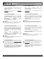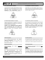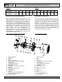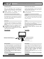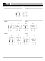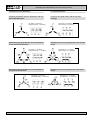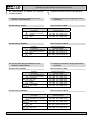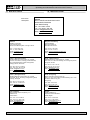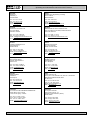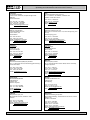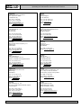
1
Betriebsanleitung Watt-Drive Motoren LABA-WDMO-1212 Betriebs- und Wartungsanleitung Operating and maintenance manual WAG-Fussmotor WAG-Foot motor B3 WAF-Flanschmotor WAF-Flange motor B5 WAC-Flanschmotor WAC-Flange motor B14 WAR-Getriebeanbaumotor WAR-Integral motor B5-special WATT Motore WATT motors BA01 MOTOR 07/2009 Deutsch - English Betriebsanleitung für WATT Motoren Operating and maintenance manual for WATT motors Inhaltsverzeichnis Seite 1. Hinweise 1.1 Allgemeine Hinweise 1.2 Sicherheits- und Hinweiszeichen 1.3 Haftungsauschluss 2. Allg. Sicherheitshinweise, Transport 4 Aufstellung des Motors Anschlusskasten Ausbrechöffnungen / Schraubverschlüsse Isolationswiderstand überprüfen Anschluss des Erdungsleiters 6. Inbetriebnahme 6.1 Checkliste - Motor 7. Betrieb Stillstandsheizung Kondenswasserbohrung Fremdlüfter Temperaturwächter TH Kaltleitertemperaturfühler TF Bremse Drehgeber 3 3 3 4 3. Electrical connection 6 6 6 7 8 4.1 4.2 4.3 4.4 4.5 9 5.1 Direction of rotation 9 10 6.1 Check lists – motor 5 5 5 4. Preperation for connecting the motor Motor installation Terminal box Knockout openings / screw cabs Checking the insulation resistance Connecting the ground conductor 6 6 6 7 8 5. Connecting the motor 10 8. Optionale Zusatzeinrichtungen 8.1 8.2 8.3 8.4 8.5 8.6 8.7 2. General safety information, transport 3.1 Proper use of the motors 3.2 Electromagnetic compatibility 3.3 Safety information 5. Anschluss des Motors 5.1 Drehrichtung 1.1 General information 1.2 Safety and information markings 1.3 Exclusion of liability 5 5 5 4. Vorbereitung Motoranschluss 4.1 4.2 4.3 4.4 4.5 Page 1. Information 3 3 3 3. Elektrischer Anschluss 3.1 Bestimmungsgemäße Verwendung der Motoren 3.2 Elektromagnetische Verträglichkeit 3.3 Sicherheitsinweise Contents 9 9 10 6. Startup 10 7. Operation 8. Optional additional devices 11 11 11 12 12 13 16 8.1 8.2 8.3 8.4 8.5 8.6 8.7 9.1 Motoren mit einer Drehzahl 9.2 Motoren mit zwei Drehzahlen 9.3 Spannungszuordnung bei Motoren mit einer Drehzahl – 6 Statorklemmen 9.4 Spannungszuordnung bei Motoren mit einer Drehzahl – 9 Statorklemmen 16 17 18 9.1 Single speed motors 9.2 Two speed motors 9.3 Voltages classification at single speed motors – 6 terminals 9.4 Voltages classification at single speed motors – 9 terminals 16 17 18 10. Watt Drive Partner 19 10. Watt Drive Partner 19 9. Motorschaltbild Anti-condensation heating Condensation drain hole Forced cooling Temperature control TH Thermistor protection TF Brake Encoder 11 11 11 12 12 13 16 9. Motor circuit diagram 18 WATT DRIVE GMBH A-2753 Markt Piesting Wöllersdorfer Str. 68 Tel.:+43/2633/404-0 Fax: +43/2633/404-220 www.wattdrive.com [email protected] 18 -2- Betriebsanleitung für WATT Motoren Operating and maintenance manual for WATT motors 1. Hinweise 1. Information 1.1 Allgemeine Hinweise 1.1 General information Die vorliegende Betriebsanleitung (BA) ist Bestandteil der Motorlieferung und muss bevor Sie mit dem Motor arbeiten gelesen werden. Die Anweisungen dieser BA sollten unbedingt eingehalten werden. Bewahren Sie die BA in der Nähe des Motors auf. These Operating Instructions (OI) are part of the motor as supplied, and you must read them before you work with the three phase motor. The instructions in the OI must be followed. Keep the OI close to the motor. Note: We assume no liability for damages or disruptions of operations resulting from the failure to observe this OI. Hinweis: Für Schäden bzw. Betriebsstörungen, die durch Nichtbeachtung dieser BA resultieren, wird keine Haftung übernommen. In order to develop the product further, Watt Drive reserves the right to make modifications to the individual components or assemblies that it believes to be useful to improve the product, while maintaining its essential characteristics. Die Firma Watt Drive behält sich in Sinne einer Weiterentwicklung das Recht vor, an den einzelnen Bauteilen bzw. Baugruppen Änderungen vorzunehmen, die unter Beibehaltung der wesentlichen Merkmale zur Verbesserung des Produkts für sinnvoll erachtet werden. Bestimmungsgemäße Verwendung: Die Drehstrom-Motoren sind für gewerbliche Anlagen bestimmt und dürfen nur entsprechend den Angaben in der technischen Dokumentation von Watt Drive eingesetzt werden. Use as intended: The three phase motors are intended for commercial systems, and may only be used in accordance with the information provided in the Watt Drive technical documentation. 1.2 Sicherheits- und Hinweiszeichen 1.2 Safety and information markings Diese Sicherheits- und Warnhinweise sind unbedingt zu beachten! All safety and warning instructions must be followed without exception! !! Warnung vor elektrischer Gefahr, z.B. Bei Arbeiten unter Spannung. !! Warning of electrical danger, e.g. working with live machines. S A Warnung vor mechanischer Gefahr, z.B. Arbeiten an Hubwerken. S A Warning of mechanical danger, e.g. working with hoisting equipment. Wichtige Anweisung störungsfreien Betrieb. für sicheren und Important instructions operation. for safe, trouble-free 1.3 Haftungsausschluss 1.3 Exclusion of liability Die Beachtung der BA ist Grundvoraussetzung für den sicheren Betrieb des Drehstrom-Motors und für die Erreichung der angegebenen Produkt-eigenschaften und Leistungsmerkmale. Für Personen-, Sach- oder Vermögensschäden, die wegen Nichtbeachtung der BA entstehen, übernimmt Watt Drive keine Haftung. Die Sachmängelhaftung ist in solchen Fällen ausgeschlossen. You must comply with the information contained in these OI to en-sure safe operation of the three phase motor and to achieve the specified product charac-teristics and performance requirements. Watt Drive assumes no liability for in-jury to persons or damage to equipment or property resulting from non-observance oft hese OI. In such cases, any liability for defects is excluded. WATT DRIVE GMBH A-2753 Markt Piesting Wöllersdorfer Str. 68 Tel.:+43/2633/404-0 Fax: +43/2633/404-220 www.wattdrive.com [email protected] -3- Betriebsanleitung für WATT Motoren Operating and maintenance manual for WATT motors 2. Allgemeine Sicherheitshinweise, Transport Die Lieferung ist nach Erhalt auf etwaige Transportschäden zu untersuchen. Die Inbetriebnahme ist gegebenenfalls auszuschließen. Der Kunde ist verantwortlich für die fachgerechte Aufstellung des Antriebes. Bestätigte Eigenschaften der Antriebe sowie die Erfüllung eventueller Garantieansprüche bedingen die Einhaltung der Hinweise in dieser Betriebsanleitung. Achten Sie darauf, niemals beschädigte Produkte in Betrieb zu nehmen! Lesen Sie die Betriebsanleitung sorgfältig, bevor Sie mit Aufstell-, Montage- oder Wartungsarbeiten beginnen. 2. General safety information, transport After being delivered, the unit must be inspected for any damage that may have occurred during transport. If the unit's condition warrants, it may be necessary to take action to prevent the unit from being put into operation. The customer is responsible for setting up the drive in accordance with good engineering practices. The instructions in these Operation Instructions must be followed to achieve the confirmed characteristics of the drive units and if any warranty claims are to be met. Make certain that you never put damaged products into operation! Read these Operating Instructions carefully before you begin any setup, installation, or maintenance work. Die verwendeten Ringschrauben entsprechen der DIN 580, die darin enthaltenen Vorschriften sind einzuhalten. Die Ringschrauben müßen fest angezogen sein. Sie sind nur für das Eigengewicht des Drehstrom-Motors ausgelegt. The ring bolts that are used comply with DIN 580; the requirements contained therein must be observed. The ring bolts must be securely tightened. They are designed to hold the motor’s own . Es dürfen keine zusätzlichen Lasten angebracht werden. No additional loads may be applied. Gewinde m [kg] M8 M10 M12 M16 M20 M24 M30 140 230 340 700 1200 1800 3600 Thread m [kg] M8 M10 M12 M16 M20 M24 M30 140 230 340 700 1200 1800 3600 Die Masse m [kg] entspricht der maximal anzuhängenden Last bei Zug in Richtung F der Schraubenachse. The mass m [kg] corresponds to the maximum dependent load in tension in direction F of the bolt axis. Die Montage, Inbetriebnahme sowie Wartungs- und Reparaturarbeiten am Drehstrom-Motor sowie an der elektrischen Zusatzausstattung dürfen nur von qualifiziertem Fachpersonal ausgeführt werden, unter Berücksichtigung folgender Punkte: Installation, startup, maintenance and repair work on the three phase motor as well as on electrical accessory equipment may only be performed by qualified technical personnel, taking the following items into account: Betriebsanleitung Hinweisschilder am Motor aller anderen zum Antrieb gehörenden Projektierungsunterlagen, Inbetriebnahmeanleitungen Anlagenspezifische Bestimmungen und Erfordernisse aktuell gültigen nationalen und regionalen Vorschriften über Sicherheit und Unfallverhütung. Operating Instructions Information labels/tags on the motor All other project documents, setup manuals, operating manuals Drive-specific specifications and requirements belonging to the drive unit the applicable regional and national regulations on safety and accident prevention. Montage- und Wartungsarbeiten sind nur bei stillstehendem Motor durchzuführen. Der Antrieb muss spannungsfrei und gegen versehentliches Einschalten abgesichert sein. Installation and maintenance work may only be performed when the motor is shut down. There must be no load on the drive and steps must be taken to prevent units from being actually turned on. Der Betrieb des Motors mittels Frequenzumrichter darf nur unter Einhaltung der Angaben am Typenschild des Motors durchgeführt werden. Operation of the drive unit by means of a frequency inverter may only occur if the specifications shown on the motor’s nameplate have been carried out. WATT DRIVE GMBH A-2753 Markt Piesting Wöllersdorfer Str. 68 Tel.:+43/2633/404-0 Fax: +43/2633/404-220 www.wattdrive.com [email protected] -4- Betriebsanleitung für WATT Motoren Operating and maintenance manual for WATT motors 3. Elektrischer Anschluss 3. Electrical connection 3.1 Bestimmungsgemäße Verwendung der Motoren 3.1 Proper use of the motors Diese Drehstrommotoren sind für gewerbliche Anlagen bestimmt. Sie entsprechen den harmonisierten Normen der Reihe IEC / EN 60034-1 (VDE 0530-1). Sie sind sowohl für Netzbetrieb als auch in Verbindung mit Frequenzumrichtern konzipiert. Der Einsatz im Ex-Bereich ist verboten. The electric motors are intended for industrial systems. They comply with the harmonized standards of the series IEC / EN 60034-1 (VDE 0530-1). They are designed both for mains operation as well as in conjunction with frequency converters. The use in potentially explosiveatmospheres is not permitted. Die Motoren in Standardausführung sind für den Betrieb bei einer Umgebungstemperatur von -20°C (-4°F) bis +40°C (104°F) sowie Aufstellungshöhen ≤ 1000m über dem Meeresspiegel bemessen. Standard motors are designed for use at temperatures of -20°C (-4°F) to +40°C (104°F) and altitudes of ≤ 1,000m above sea level. 3.2 Elektromagnetische Verträglichkeit 3.2 Electromagnetic compatibility Die Maschinen in geschlossener Bauform (IP 55 und höher) erfüllen bei bestimmungsgemäßer Verwendung, betrieben am elektrischen Versorgungsnetz mit den Merkmalen gemäß EN 50160, die Anforderungen der Richtlinie über die Elektromagnetische Verträglichkeit 89/336/EWG. When used in accordance with their intended purpose and operated in an electrical supply system with characteristics to EN 50160, the enclosed motors (IP 55 and higher) comply with the requirements of the EC Directive concerning electromagnetic compatibility 89/336/EEC. 3.3 Sicherheitshinweise 3.3 Safety information Alle Arbeiten dürfen nur von qualifizierten Fachpersonal - am stillstehenden Motor - im freigeschalteten und - gegen Wiedereinschalten gesicherten Zustand vorgenommen werden. Work is only permitted to be carried out by qualified specialists - on the stationary motor - while disconnected and - prevented form being switched on again. This also applies for the auxiliary power circuits (e.g. optional anti-condensation heaters). Dies gilt auch für Hilfsstromkreise (z.B. Optionale Stillstandsheizung). !! Vor Beginn der Arbeiten verbindung herstellen! Spannungsfreiheit prüfen ! sichere Schutzleiter- Überschreiten der Toleranzen in EN 60034-1 (VDE 0530,Teil1) – Spannung + 5%,Frequenz + 2%, Kurvenform, Symmetrie - erhöht die Erwärmung und beeinflusst die elektromagnetische Verträglichkeit. Typenschildangaben sowie das Schaltbild im Anschlusskasten beachten. !! Before starting work, make sure that a protective conductor is securely connected! Check for isolation from supply! Exceeding the tolerances in EN 60034-1 (VDE 0530, part1) – voltage + 5 %, frequency+ 2 %, curve shape, symmetry - increases the temperature and influences electromag-netic compatibility. Observe nameplate data and the wiring diagram in the terminal box. WATT DRIVE GMBH A-2753 Markt Piesting Wöllersdorfer Str. 68 Tel.:+43/2633/404-0 Fax: +43/2633/404-220 www.wattdrive.com [email protected] -5- Betriebsanleitung für WATT Motoren Operating and maintenance manual for WATT motors 4. Vorbereitung Motoranschluss 4. Preparation for connecting the motor 4.1 Aufstellung des Motors 4.1 Motor installation Die Aufstellung hat so zu erfolgen, daß der Zutritt von Frischluft und das Abströmen der Warmluft ungehindert erfolgen kann. Es ist verboten den Lüfterflügel und die Lüfterhaube zu entfernen bzw. den Motor in ein Gehäuse einzuschließen, da in beiden Fällen die Kühlluftzufuhr verringert wird. Dadurch würde der Motor überhitzt werden. When installing the motor, ensure that the intake is not obstructed and air can circulate freely. Do not remove the fan blade or cowl, or enclose the motor with a casing because in both cases there would not be enough air for cooling and the motor could overheat. 4.2 Anschlusskasten 4.2 Terminal box Im Anschlusskasten dürfen sich keine Fremdkörper, Schmutz sowie Feuchtigkeit befinden. Weitere offene Einführungen sind mit O-Ring oder geeigneter Flachdichtung, der Anschlusskasten selbst mit der Originaldichtung staub- und wasserdicht zu verschließen. It must be ensured that there are no foreign bodies, dirt or moisture in the terminal box. Open entries are to be sealed with an O ring or a suitable flat gasket so that dust and water cannot enter, whereas the terminal box itself is to be sealed against dust and water with the original seal. Anschlusskasten, Klemmenbrett, Kabelanschlüsse, etc. im Innenraum des Anschlusskastens dürfen nicht beschädigt werden! !! !! Achtung! Der Anschlusskasten muss staub- und wasserdicht verschlossen sein! It must be ensured that the terminal box, terminal board and cable connections etc. inside the terminal box are not damaged. !! Attention! The terminal box must be sealed so that dust and water cannot enter. 4.3 Ausbrechöffnungen / Schraubverschlüsse 4.3 Knockout openings / screw cabs Die Ausbrechöffnungen im Anschlusskasten der WAMotoren sind sachgerecht auszuschlagen (Bild 3, Seite 32). Anschlusskasten sowie Klemmenbrett, Kabelanschlüsse, etc. im Innenraum des Anschlusskastens dürfen nicht beschädigt werden! 7WA-Motoren besitzen Schraubverschlüsse. Knockout openings in the terminal box of the WA motors must be knocked out appropriately (Fig. 3, page 32). Care must be taken to ensure that the terminal box and the terminal board and cable connections, etc., that it contains are not damaged. 7WA motors are equipped with a srew cab. Achtung! Schutzbrille verwenden - Gefahr durch Bruchstücke - Anschlusskastendeckel aufsetzen und verschließen - Zu öffnende Kabeleinführung festlegen - Kabeleinführung öffnen: - mit Meißel o.ä. (schräg ansetzen) - durch leichten Hammerschlag Vorsicht! Nicht ins Innere des Anschluss durchschlagen! - Anschlusskasten öffnen, ggf. ausgebrochenes ‘ Verschlussstück entfernen Montage der Verschraubungen: Die Verschraubungen müssen auf die verwendeten Anschlusskabel abgestimmt sein (Bewehrung, Geflecht, Abschirmung) - Kabelverschraubung durch beiliegende Kontermutter sichern - Kabeleinführung abdichten !! Attention! Wear safety glasses - danger of injury from fragments! - Put on the terminal box cover and fasten with screws - Determine which cable entries to open - Open the cable entries: - with a chisel or similar (hold at angle) - by a light tap with a hammer Caution! Do knock through to the inside of the terminal box! - Open the terminal box, remove the knockout cover if it has broken off. Assembling of the cable screw fittings: The screw-type connections must have been matched to the connecting cables used (armoring, braid, shield). - Secure the cable screw fittings with the supplied lock nuts. - Seal the cable entry WATT DRIVE GMBH A-2753 Markt Piesting Wöllersdorfer Str. 68 Tel.:+43/2633/404-0 Fax: +43/2633/404-220 www.wattdrive.com [email protected] -6- Betriebsanleitung für WATT Motoren Operating and maintenance manual for WATT motors !! Bild 3: Ausbrechöffnungen (nur bei WA-Motoren) Fig. 3: Knockout openings (with WA motors only) 4.4 Isolationswiderstand überprüfen 4.4 Checking the insulation resistance Eine Prüfung des Isolationswiderstandes ist vor Inbetriebnahme sowie nach längerer Lagerung oder Stillstandszeit erforderlich! Beachten Sie vor Beginn der Messung des Isolationswiderstandes die Bedienungsanleitung des verwendeten Isolationsmessgerätes. Zur Isolationsmessung sind bereits angeschlossene Kabel des Hauptstromkreises wieder von den Klemmen zu entfernen. The insulation resistance needs to be checked prior to start-up and again after any extended periods of storage or periods during which the equipment is not in operation. Before you begin measuring the insulation resistance, please read the manual for the insulation resistance meter you are going to use. Any cables of the main circuit which are already connected should be disconnected from the terminals in order to carry out the insulation measurements. Attention! During the measurement, and immediately afterwards, some of the terminals are at hazardous voltage levels and must not be touched. Carry out a check with the power cables connected that no voltage can be applied. Achtung! Die Klemmen haben bei der Messung, sowie unmittelbar nach der Messung, teilweise gefährliche Spannungen und dürfen nicht berührt werden. Stellen Sie bei angeschlossenen Netzleitungen sicher, dass keine Spannung angelegt werden kann. Messen Sie den Mindestisolationswiderstand der Wicklung gegen das Maschinengehäuse möglichst bei einer Wicklungstemperatur von +20 °C bis +30 °C. Für andere Temperaturen gelten andere Werte für den Isolationswiderstand. Bei der Messung muss abgewartet werden, bis der Endwert des Widerstandes erreicht ist (ca. 1 Minute). A A Achtung! Wird der kritische Isolationswiderstand erreicht oder unterschritten, müssen die Wicklungen getrocknet bzw. bei ausgebautem Läufer gründlich gereinigt und getrocknet werden. Beachten Sie nach dem Trocknen gereinigter Wicklungen, dass der Isolationswiderstand bei warmer Wicklung kleiner ist. Der Isolationswiderstand lässt sich nur nach Umrechnung auf die Referenztemperatur +25 °C richtig beurteilen. Achtung! Liegt der gemessene Wert nahe am kritischen Wert, den Isolationswiderstand in der Folgezeit in entsprechend kurzen Intervallen kontrollieren. Die folgende Tabelle 2 Seite 33 gibt die Messspannung sowie den Mindest-Isolationswiderstand und den kritischen Isolationswiderstand an. Werte gelten für eine Wicklungstemperatur von +25 °C. !! Where possible, measure the minimum insulation resistance of the winding to the motor enclosure when the winding temperature is between +20 °C and +30 °C. For other temperatures, different values apply to the insulation resistance. When taking the measurement, you must wait until the final resistance value is reached (approximately 1 minute). A Attention! If the critical insulation resistance is less than or equal to this value, the windings must be dried or, if the fan is removed, cleaned thoroughly and dried. Note that the insulation resistance of dried, clean windings is lower than that of warm windings. The insulation resistance can only be properly assessed after conversion to the reference temperature of +25 °C. A Attention! If the measured value is close to the critical value, you must subsequently check the insulation resistance at appropriately frequent intervals. The following table 2 page 33 indicates the measuring circuit voltage together with the minimum insulation resistance and the critical insulation resistance. Values apply at a winding temperature of +25 °C. WATT DRIVE GMBH A-2753 Markt Piesting Wöllersdorfer Str. 68 Tel.:+43/2633/404-0 Fax: +43/2633/404-220 www.wattdrive.com [email protected] -7- Betriebsanleitung für WATT Motoren Operating and maintenance manual for WATT motors Tabelle 2: Isolationswiderstand Messspannung Mindest-Isolationswiderstand bei neuen, gereinigten oder instand gesetzten Wicklungen Kritischer spezifischer Isolationswiderstand nach langer Betriebszeit Measuring circuit voltage Minimum insulation resistance with new, cleaned or repaired windings Critical specific insulation resistance after a long operating time Table 2: Insulation resistance Bemessungsspannung UN < 2 kV 500 V 10 MΩ 0,5 MΩ/kV Rated voltage Urated < 2 kV 500 V 10 MΩ 0.5 MΩ/kV Folgende Punkte sind hierbei noch zu beachten: Also note the following points: Bei Messung mit anderen Wicklungstemperaturen als +25 °C muss der gemessene Wert auf die Referenztemperatur +25 °C umgerechnet werden. Pro 10 K Temperaturanstieg halbiert sich der Isolationswiderstand, pro 10 K Temperaturabfall verdoppelt sich der Widerstand. When measuring at winding temperatures other than +25 °C, the measured value must be converted to the reference temperature of +25 °C. The insulation resistance is reduced by a factor of a half for every 10 K increase in temperature, and it is increased by a factor of two for every 10 K decrease in temperature. Trockene, neuwertige Wicklungen haben Isolationswiderstände zwischen 100 bis 2.000 MΩ, gegebenenfalls auch höhere Werte. Liegt der Isolationswiderstandswert in der Nähe oder unterhalb des Mindestwertes, so können Feuchtigkeit und/oder Verschmutzung die Ursache sein. Die Wicklungen sind dann zu trocknen. New, dry windings have an insulation resistance of between 100 and 2,000 MΩ, or even higher values in some cases. If the insulation resistance is close to or below the minimum value, the cause could be humidity and/or dirt accumulation. The windings must then be dried. Während der Betriebszeit kann der Isolationswiderstand der Wicklungen durch Umwelt- und Betriebseinflüsse auf den kritischen Isolationswiderstand sinken. Der kritische Wert des Isolationswiderstandes bei einer Wicklungstemperatur von +25 °C ist je nach Bemessungsspannung durch Multiplikation der Bemessungsspannung (kV) mit dem spezifischen kritischen Widerstandswert (0,5 MΩ/kV) zu errechnen; z.B. kritischer Widerstand für Bemessungsspannung (UN) 690 V: 1000 V x 0,5 MΩ/kV = 0,345 MΩ During operation, the insulation resistance of the windings can fall to the critical insulation resistance due to ambient and operational influences. Depending on the rated voltage, the critical insulation resistance for a +25 °C winding temperature can be calculated by multiplying the rated voltage (kV) by the specific critical resistance value (0.5 MΩ/kV); e.g. critical resistance for a rated voltage (UN) 690 V: 690 V x 0.5 MΩ/kV = 0.345 MΩ 4.5 Anschluss des Erdungsleiters 4.5 Connecting the ground conductor Die Erdung muß mit dem Anschluss im Anschlusskasten an der dafür vorgesehenen und entsprechend gekennzeichneten Stelle durchgeführt werden. The grounding has to be connected in terminal box at the place intended for this purpose and marked accordingly. Der Erdungsleiterquerschnitt der Maschine muss mit den Errichtungsbestimmungen, z.B. nach DIN EN IEC 602041 übereinstimmen. Beim Anschließen ist zu beachten, dass - die Anschlussfläche kontaktblank und mit geeignetem Mittel gegen Korrosion geschützt ist, z.B. mit säurefreier Vaseline. - der Kabelschuh zwischen die Klemmbügel eingelegt wird. - der Federring unter dem Schraubenkopf angeordnet ist. The cross-section of the ground conductor of the machine must comply with the regulations for electrical installations, e.g. DIN EN IEC 60204-1. Please note the following when connecting-up: - The contact surface must be clean and bright, and protected with a suitable anti-corrosion agent, e. g. acid-free Vaseline. - The cable lug must be inserted between the terminal clips. - The spring washer must be under the head of the screw. WATT DRIVE GMBH A-2753 Markt Piesting Wöllersdorfer Str. 68 Tel.:+43/2633/404-0 Fax: +43/2633/404-220 www.wattdrive.com [email protected] -8- Betriebsanleitung für WATT Motoren Operating and maintenance manual for WATT motors Table 3: Minimum surface area Tabelle 3: Mindestquerschnittsfläche Mindestquerschnittsfläche des Phasenleiters der Isolation Minimum surface area of insulation phase conductor S mm2 S ≤ 16 16 < S ≤ 35 S > 35 5. Anschluss des Motor !! mm2 S 16 0,5 S 5. Connecting the motor Der Anschluss des Motors erfolgt nach dem AnschlussSchaltbild, welche dem Motor im Anschlusskasten beigefügt sind. Connect the motor only as shown in the wiring diagram included in the terminal box of the motor. Es muss eine dauerhaft sichere, elektrische Verbindung aufrecht erhalten werden (keine abstehenden Drahtenden); zugeordnete Kabelendbestückung verwenden. Connections must be made in such a way as to ensure that a permanently safe electrical connection is maintained (no protruding wire ends); use the corresponding cable end pieces. Achtung! Ein Motorschutzschalter bzw. ein Schutz mit Überstromrelais zum Schutz der Motorwicklungen sollte installiert werden. Schmelzsicherungen schützen den Motor nicht vor Überlastungen sondern lediglich die Netzzuleitungen oder Schaltanlagen gegen Schäden bei Kurzschluß. !! 5.1 Direction of rotation Standardmäßig sind die Motoren für Rechts- und Linkslauf geeignet. Wenn die Netzleitungen mit der Phasenfolge L1, L2, L3 an U1, V1, W1 angeschlossen werden, ergibt sich Rechtslauf (Blick auf antriebsseitiges Wellenende). Werden zwei Anschlüsse vertauscht, ergibt sich Linkslauf (z.B. L1, L2, L3 an V1, U1, W1). The standard motors are suitable for clockwise and counter-clockwise rotation. Connection of the power cables in the phase sequence L1, L2, L3 to U1, V1, W1 results in clockwise rotation (looking at the shaft end on the drive side). If two connections are interchanged, this results in counterclockwise rotation (e.g. L1, L2, L3 to V1, U1, W1). Für den Probebetrieb ohne Abtriebselemente Passfeder sichern. 6. Startup S Bei den Motoren mit Bremse vor der Inbetriebnahme die einwandfreie Funktion der Bremse prüfen. A Attention! A motor circuit breaker or contactor with an overcurrent relay should be installed to prevent the motor winding from burning out. Fuses do not stop the motor overloading, but merely protect the power cables or switchgear from damage in the event of a short circuit. 5.1. Drehrichtung 6. Inbetriebnahme S Mindestquerschnittsfläche des zugehörigen Erdungsanschlusses Minimum surface area of corresponding ground connection Achtung! Vor jedem Einschalten muss sichergestellt sein, dass die optionale Stillstandsheizung ausgeschaltet wird. Secure the featherkey on test operation without drive components. For motors with brakes, check that the brakes are operating perfectly before commissioning. A Attention! Before energizing the motor, always make sure that the optional anti-condensation heating is switched off. WATT DRIVE GMBH A-2753 Markt Piesting Wöllersdorfer Str. 68 Tel.:+43/2633/404-0 Fax: +43/2633/404-220 www.wattdrive.com [email protected] -9- Betriebsanleitung für WATT Motoren Operating and maintenance manual for WATT motors 6.1 Checkliste – Motor 6.1 Check lists – motor Vor Inbetriebnahme des Motors ist zu überprüfen: Check the following before starting up the motor: Informationen siehe Kapitel Stimmt die Netzspannung und Frequenz mit den angeführten Daten am Motorleistungsschild überein. Wurden alle Anschlüsse ordnungsgemäß ausgeführt (Motoranschluss, Erdungsleiter,…)? Ist der Motoranschluss ident mit dem beiliegendem Schaltbild? Stimmt die Drehrichtung des Motors? Anschlusskasten staub- und wasserdicht verschlossen? Motorschutzschalter installiert? Sind alle Motorschutzeinrichtungen aktiv und auf den Bemessungsstrom des Motors eingestellt ? Isolationswiderstand überprüft? Optionale Stillstandsheizung ausgeschalten? Optionale Fremdlüftung an eine externe Stromversorgung angeschlossen? 4.5, 5. 5.1 4.2 5. 4.4 8.1 8.3 Informations see chapter Check that the mains voltage and frequency correspond to the data on the motor rating plate. All connections have been made properly (motor connection, ground conductor,…)? Is the direction of rotation of the motor/geared motor correct? Is the terminal box dust and watertight? Is a motor circuit breaker installed? Are all motor protection equipments active and set for the rated motor current? Has the insulation resistance been checked? Optional anti-condensation heating is switched of? Optional forced cooling is connect with a external power supply? 7. Betrieb Geprüft checked 4.5, 5. 5.1 4.2 5. 4.4 8.1 8.3 7. Operation Schwingstärken Veff = 3,5 mm/s (PN = 15 kW) bzw. Veff = 4,5mm/s (PN > 15 kW) sind im gekuppelten Betrieb unbedenklich. Vibration levels of Vrms = 3,5 mm/s (PN = 15 kW) or Vrms = 4,5mm/s (PN > 15 kW) are quiet acceptable in the coupled state. Bei Veränderungen gegenüber dem Normalbetrieb z.B. erhöhte Temperaturen, Geräusche, Schwingungen Ursache ermitteln, eventuell Rücksprache mit dem Hersteller. Schutzeinrichtungen auch im Probebetrieb nicht außer Funktion setzen. Im Zweifelsfall Motor abschalten. Whenever changes occur in relation to normal operation, such as increased tempera-tures, noise, oscillation, determine the cause and contact the manufacturer, if required.Never bypass or disable protection devices, not even in test mode. If you are in doubt, switch off the motor. A Bei starkem reinigen. Schmutzanfall Luftwege regelmäßig A Regularly clean air ducts in dusty or dirty environments. A Eventuell vorhandene Kondenswasserstopfen von Zeit zu Zeit entfernen und anschließend wieder montieren. A Remoce the optionally condensation water plug to drain from time to time and reinsert the plug. A Die optionale Stillstandsheizung darf während des Motorbetriebes nicht eingeschalten werden. A The optional anti-condensation heating must not be switched on during the motor running. WATT DRIVE GMBH A-2753 Markt Piesting Wöllersdorfer Str. 68 Tel.:+43/2633/404-0 Fax: +43/2633/404-220 www.wattdrive.com [email protected] - 10 Betriebsanleitung für WATT Motoren Operating and maintenance manual for WATT motors 8. Optionale Zusatzeinrichtungen A 8. Optional additional devices Bremse, Inkrementalgeber, Temperaturwächter, Stillstandsheizung, Fremdlüftung,… sind nur auf besondere Bestellung vorhanden. Brake, encoder, temperature controller, anti condensation heating, forced ventilation,… are present only on special order. Zusatzeinrichtungen sind nach Schaltbildern anzuschließen. Additional devices are to be connected after the valid wiring diagrams. den beiliegenden 8.1 Stillstandsheizung (Option) 8.1 Anti-condensation heating (optional) Bei besonderen Klimaverhältnissen z.B. bei starken Temperaturschwankungen oder bei stillstehenden Motoren in feuchter Atmosphäre kann eine Stillstandsheizung vorgesehen werden. Die Beschaltung des Heizelementes ist im Anschlusskasten des Motors ersichtlich. Under certain climatic conditions an anti- condensation heater may be required e.g. when there are great fluctuations in temperature or the motor is at rest in a humid atmosphere. For heater connection, see the motor terminal box. Achtung! Vor jedem Einschalten muss sichergestellt sein, dass die optionale Stillstandsheizung ausgeschaltet wird. 18.2 Condensate drain hole (optional) Bei Motoren, die starken Temperaturschwankungen oder extremen klimatischen Verhältnissen ausgesetzt sind, kann im Inneren Luftfeuchtigkeit kondensieren. In diesem Fall empfehlen wir eine optionale Kondeswasserbohrung. If motors are subject to great fluctuations in temperature or extreme climatic conditions, humid air can condense inside the machine. We recommend using a condensate drain hole. Remove the condensation water plug to drain the water. Afterwards, reinsert the plug. A Attention! Before installing motors with condensate drain holes, check that the mounting position is correct. Achtung! Bei Motoren mit Kondenswasserbohrungen ist auf die richtige Einbaulage zu achten! 8.3 Fremdlüfter (Option) A Attention! Before energizing the motor, always make sure that the (optional) anti-condensation heating is switched off. 8.2 Kondenswasserbohrung (Option) Entfernen Sie daher in Abhängigkeit von den Umgebungsund Betriebsbedingungen den Kondenswasserstopfen zum Ablassen des Wassers. Stopfen anschließend wieder montieren. A A Der Fremdlüfter muss nach beiliegendem Schaltbild (siehe Anschlusskasten Fremdlüfter) an eine externe Versorgungsspannung angeschlossen werden. Bei Betrieb des Motors an einem Frequenzumrichter darf der Fremdlüfter nicht an den Frequenzumrichter angeschlossen werrden sondern muß an ein EXTERNE Versorgungsspannung angeschlossen werden. 8.3 Forced cooling (optional) A The forced cooling must be connected according to wiring diagram (see in forced cooling terminal box ). If the motor is operated with an frequency inverter, it´s not allowed to connect the forced cooling on the frequency inverter. Connect the forced cooling to a EXTERNAL power supply. WATT DRIVE GMBH A-2753 Markt Piesting Wöllersdorfer Str. 68 Tel.:+43/2633/404-0 Fax: +43/2633/404-220 www.wattdrive.com [email protected] - 11 Betriebsanleitung für WATT Motoren Operating and maintenance manual for WATT motors 8.4 Temperaturwächter TH (Option) 8.4 Temperature controller TH (optional) Temperaturwächter sind kleine Bimetallschalter, die beim Überschreiten der Ansprechtemperatur einen Kontakt öffnen oder schließen. Der Öffnungskontakt trennt den Erregerkreis des Motorschützes und die Spannungsversorgung des Motors wird damit getrennt. Thermostats have small bimetallic strips that make or break a contact when the critical temperature is reached. The break contact opens the field circuit and disconnects the power supply to the motor. Farbe: rot Colour: red 8.5 Kaltleitertemperaturfühler TF (Option) 8.5 Thermistor protection TF (optional) Kaltleitertemperaturfühler sind Halbleiter, bei denen der ohmsche Widerstand bei Erreichen der Bemessungsansprechtemperatur extrem ansteigt. Zusätzlich zu den Kaltleiterfühlern ist ein Auslösgerät notwendig. Das im Auslösegerät befindliche Relais mit einem Wechselkontakt kann nach Bedarf zum Unterbrechen des Erregerkreises des Motorschützers oder zum Auslösen eines Warnsignals verwendet werden. PTC thermistors are semi-conductors whose electrical resistance increases dramatically when the critical temperature is reached. In addition to the PTC thermistor, a control unit is also required. The relay in the tripping unit has a changeover contact, which can either be used to open the excitation circuit in the motor contactor or trigger a warning signal. Farbe: gelb Colour: yellow 8.6 Bremse (Option) 8.6 Brake (optional) Die Einscheiben-Federdruckbremse wird elektrisch gelüftet. Der Bremsvorgang erfolgt mechanisch nach Ausschalten der Spannung. Die Bremsen sind bei der Lieferung auf das Bremsmoment eingestellt. The single-disc brake is released electrically. The brake is applied mechanically when the voltage is switched off. Anschluss der Bremse Connecting the brake Bremsenansteuerung nach Schaltbild anschließen. jeweils beiliegendem At delivering the brakes are adjusted to the brake torque. Connect the brake control system according to the circuit diagram supplied with the brake. Wartung Maintenance Die WATT-Federdruckbremsen sind nahezu wartungsfrei. Es ist zu empfehlen, den Luftspalt “a” in bestimmten Zeitabständen zu überprüfen, um ein sicheres Lüften der Bremse zu gewährleisten. Ein erforderliches Einstellen des Luftspaltes “a” kann nach Tabelle 4 erfolgen. The WATT spring-loaded brakes hardly need any maintenance. However we recommend checking air gap "a" periodically to ensure safe brake release. Adjust air gap "a" to the figures given in table 4 below if necessary. WATT DRIVE GMBH A-2753 Markt Piesting Wöllersdorfer Str. 68 Tel.:+43/2633/404-0 Fax: +43/2633/404-220 www.wattdrive.com [email protected] - 12 Betriebsanleitung für WATT Motoren Operating and maintenance manual for WATT motors Table 4: Tabelle 4: Bremsmoment Brake torque a (normal) a (maximum) [Nm] 2 5 10 20 40 60 100 150 250 400 800 [mm] [mm] 0,2 0,6 0,2 0,6 0,2 0,7 0,3 0,8 0,3 0,9 0,3 1 0,4 1,1 0,4 1,1 0,5 1,2 0,5 1,2 0,6 1,3 Nachstellen des Bremsluftspaltes (Bild 4) Readjustment of air gap (Fig. 4) Zuerst werden die drei Befestigungsschrauben (10) eine halbe Umdrehung gelöst. Nun lassen sich die Hülsenschrauben (18) durch Drehen gegen den Uhrzeigersinn in den Magnetkörper (8) hineindrehen. Durch Drehen der drei Befestigungsschrauben (10) im Uhrzeigersinn läßt sich der Magnetkörper (8) in Richtung Ankerscheibe (6) so weit bewegen, bis der Nennluftspalt, (siehe Tabelle 4) erreicht ist. Jetzt werden die drei Hülsenschrauben (18) wieder im Uhrzeigersinn bis zur festen Anlage aus dem Magnetkörper (8) herausgeschraubt und die Befestigungsschrauben (10) nachgezogen. Der Luftspalt “a” muß jetzt noch auf Gleichmäßigkeit mit einer Fühlerlehre kontrolliert und gegebenenfalls korrigiert werden. First of all the three fixing screws (10) must be unscrewed a half turn. Now the sleeve screws (18) can be screwed into the magnet case (8) by turning contraclockwise. By turning the three fixing screws (10) clockwise, the magnet case (8) can be moved in direction to the armature disc (6), as long as the nominal air gap (see at table 4) is obtained. Now the three sleeve screws (18) will be unscrewed clockwise from the magnet case (8) and the fixing screws (10) will be fixed. Please check the air gap 'a' with a feeler gauge, if it is symmetrical and adjust it if necessary. Bild 4: Explosionsdarstellung Bremsenanbau Fig. 4: Exploded view Brake 1 2 3 4 5 6 7 8 9 10 11 12 13 14 15 16 17 18 1 2 3 4 5 6 7 8 9 10 11 12 13 14 15 16 17 18 Bremslagerschild Paßfeder Welle Mitnehmer-Zahnnabe Bremsscheibe (Rotor) mit Reibbelägen Ankerscheibe Handlüftbügel (optional) Spulenträger mit Spule Federringe Zylinderschrauben mit Innensechskant Paßfeder Bremswellenverlängerung Lüfterflügel Sicherungsring Scheibe Zylinderschrauben mit Innensechskant Lüfterhaube Bremsausführung Hülsenschrauben Brake-endshield Key Shaft Gear hub Brake-disc (Rotor) with friction linings Armature disc Hand release bracket (optional) Coil holder with coil Washers Socket head cap crew Key Brake shaft adapter Fan Retaining ring Disc Socket head cap crew Fan cover brake execution Sleeve screws WATT DRIVE GMBH A-2753 Markt Piesting Wöllersdorfer Str. 68 Tel.:+43/2633/404-0 Fax: +43/2633/404-220 www.wattdrive.com [email protected] - 13 Betriebsanleitung für WATT Motoren Operating and maintenance manual for WATT motors A A Handlüftung (Option) Manual brake release (optional) Dient zum mechanischen Lüften der Bremse bei Stromausfall. Durch betätigen des Handlüftungshebels wird die Ankerscheibe angezogen und die Bremse entlüftet. An der Einstellung der Handlüftung darf aus Sicherheitsgründen nichts verändert werden. Is used to lift the brake when in case of a loss of power supply. By pressing the lever the anchor plate is pulled to the magnet and the brake is lifted. A For saftey reasons the adjustment of the manual release must not be changed. Arretierungvorrichung des Handhebels (Option) Locking device for the hand release bracket (optional) Die Handlüftung kann im Servicefall mit einer Arretierung fixiert werden. Sicherzustellen ist dass die Arretierung im Nennbetrieb die Bremse freigibt. In case of service the manual brake release can be fixed with a locking device. Take care that in rated conditon the brake is released. Gleichrichter Rectifier Serienmäßig werden Bremsmotoren mit angeschlossenem Gleichrichter für wechselstromseitiges Schalten geliefert. Für gleichstromseitiges Schalten ist die Brücke zwischen den Klemmen 5 und 6 zu entfernen und ein Schaltkontakt anzuschließen (siehe Bild 5, Seite 39). Der Motor darf nur mit angeschlossener Bremse eingeschaltet werden. (Prüfen!) Brake motors will be delivered as standard with connected rectifier for AC-side switching. For DC-side switching the bridge between terminals 5 and 6 must be removed and a switching contact must be connected (see Fig. 5, page 39). Start-up of motor only with connecting brake. (Check!) A Fig. 5: Rectifier Bild 5: Gleichrichter 1 2 3 4 5 6 ~ ~ + Anschluss am Klemmbrett (AC, V~) Connection to terminal board (AC, V~) Kontakt für DC-Schaltung Contact for DC switching Bremse / brake Stromversorgung Power supply Die Gleichstrom-Bremsspule wird normalerweise über einen im Motor-Klemmkasten eingebauten Gleichrichter gespeist und ist für Spulenspannung 162-236 VDC, 85133 VDC oder 24 VDC lieferbar (24V mit Blockklemme für externe Stromversorgung!). Zum Schutz gegen Überspannungen sind die Gleichrichter mit Varistoren beschaltet. Maximale Umgebungstemperatur +80°C. Bei Schalthäufigkeit über 1/s wegen GleichrichterBelastung rückfragen! Der Anschluß des Bremssystems erfolgt über einen im Klemmenkasten eingebauten Gleichrichter entsprechend dem jeweils beigefügten Schaltbild. The DC brake coil is normally supplied with power from a rectifier installed in the motor terminal box which is available for 162-236 VDC, 85-133 VDC or 24 VDC coil voltage (24V with block terminal for external power supply). The rectifiers are equipped with varistors to protect them against overvoltage. Max. ambient temperature for rectifiers is +80°C. For starting frequency above 1/s, contact us for rectifier loading capacity! The braking system is connected with a rectifier installed in the terminal box in accordance with the enclosed circuit diagram. WATT DRIVE GMBH A-2753 Markt Piesting Wöllersdorfer Str. 68 Tel.:+43/2633/404-0 Fax: +43/2633/404-220 www.wattdrive.com [email protected] - 14 Betriebsanleitung für WATT Motoren Operating and maintenance manual for WATT motors A Einweggleichrichter (Standard) - Anschluss: Wechselspannung 100% z.B. 400 V~ Gleichspannung 45% z.B. 180 V= Half-wave rectifier (standard version) - Connection: AC voltage 100% e.g. 400 V a.c DC voltage 45% z.B. 180 V d.c. Brückengleichrichter - Anschluss: Wechselspannung 100% z.B. 230 V~ Gleichspannung 89% z.B. 205 V= Bridge rectifier - Connection: AC voltage 100% e.g. 230 V a.c DC voltage 89% z.B. 205 V d.c. Achtung! Bei Betrieb eines Bremsmotors mit Frequenzumrichter ist die Bremsspule an eine externe Spannungsversorgung anzuschließen. A Warning! If a brake motor is operated with a frequency converter, connect the brake coil to an external power supply. 8.7 Drehgeber 8.7 Encoder Dieser Geber ist ein Präzisionsmessgerät. Die Angaben und Hinweise in den Datenblättern sind zu beachten um eine problemlose Funktion des Gebers zu gewährleisten und die Garantieleistung aufrecht zu erhalten. This encoder is a precision measuring instrument. Always observe the information and instructions of the datasheet to nsure trouble-free function and to maintain warranty claims. Bitte beachten sie unbedingt folgende Punkte: Please observe absolutely the following points: Der Drehgeber darf weder teilweise noch ganz zerlegt oder modifiziert werden. Die Welle darf nicht nachträglich bearbeitet (schleifen, bohren, sägen, usw) werden.Die Genauigkeit des Gebers und die Zuverlässigkeit von Lager und Dichtung nehmen sonst Schaden. Das Gerät niemals mit dem Hammer ausrichten. Schlagbelastungen unbedingt vermeiden. Drehgeberwelle nicht über die in den Datenblättern angegebenen Werte belasten. Drehgeber und Antriebsgerät nicht an Wellen und Flanschen starr miteinander verbinden. Angebaute Drehgeber keinesfalls als Hilfe zum Heben der Arbeitsmaschine benützen. Angebaute Drehgeber keinesfalls als Tritthilfe benützen Belegung Standardgeber: Assignment standard encoder : KÜBLER SIGNAL Code BK BN RD 0V +UB GRD 0V M23 X 1 Flanschdose / can Gehäuse case 10 11 12 Kabel / cable PH WH GYPK BN Colour/Farbe Black / Schwarz Brown / Braun Red / Rot Code OG YE GN Sens Colour/Farbe Orange Yellow / Gelb Green / Grün Code BU VT GY +UB It is not permissible to dismantle the encoder entirely or in part or to modify it. Do not alter the shaft (by grinding, sawing, drilling, etc.), otherwise the accuracy of the encoder and the reliability of bearing and seal will suffer. Never align the instrument with a hammer. It is imperative to avoid impact loads. Observe maximal radial and axial loads to the encodershaft under any circumstances. Do not connect encoder and drive rigidly to one another at shafts and flanges. Never use the assembled encoder to lift the driveunit. Never step onto the encoder. A AINV B BINV 0 0INV U As - - 2 5 6 8 1 3 4 - 9 7 BURD GN YE GY PK BU RD - - - Sens Colour/Farbe Blue / Blau Violet / Violett Grey / Grau Code WH PK GD Colour/Farbe Code Colour/Farbe White / Weiss TQ Turquoisa / Türkis Pink / Rosa SR Silver/ Silber Gold WATT DRIVE GMBH A-2753 Markt Piesting Wöllersdorfer Str. 68 Tel.:+43/2633/404-0 Fax: +43/2633/404-220 www.wattdrive.com [email protected] - 15 Betriebsanleitung für WATT Motoren Operating and maintenance manual for WATT motors 9. Motorschaltbild 9. Motor circuit diagram 9.1 Motoren mit einer Drehzahl 9.1 Single speed motors 6 Statorklemmen 6 terminals 9 Statorklemmen 9 terminals Variante 1: Version 1: Variante 2: Version 2: WATT DRIVE GMBH A-2753 Markt Piesting Wöllersdorfer Str. 68 Tel.:+43/2633/404-0 Fax: +43/2633/404-220 www.wattdrive.com [email protected] - 16 Betriebsanleitung für WATT Motoren Operating and maintenance manual for WATT motors 9.2 Motoren mit zwei Drehzahlen 9.2 Two speed motors Schaltung für Motoren mit zwei Drehzahlen und zwei getrennten Wicklungen: Circuit for two speed motors with two separate windings: low speed, Y-connection niedrige Drehzahl, Y-Schaltung Dahlanderschaltung für Motoren mit zwei Drehzahlen und konstantem Drehmoment: low speed, - connection niedrige Drehzahl, - Schaltung Dahlanderschaltung für Motoren mit zwei Drehzahlen und quadrat. Drehmoment: low speed, Y- connection niedrige Drehzahl, Y- Schaltung high speed, Y-connection hohe Drehzahl, Y-Schaltung Dahlander circuit for two speed motors with constant torque: high speed, YY - connection hohe Drehzahl, YY - Schaltung Dahlander circuit for two speed motors with square torque: high speed, YY - connection hohe Drehzahl, YY - Schaltung WATT DRIVE GMBH A-2753 Markt Piesting Wöllersdorfer Str. 68 Tel.:+43/2633/404-0 Fax: +43/2633/404-220 www.wattdrive.com [email protected] - 17 Betriebsanleitung für WATT Motoren Operating and maintenance manual for WATT motors ! Die Grundschaltung ist anhand des Leistungsschildes ersichtlich. ! The basic connection is shown in the name plate. 9.3 Spannungszuordnung bei Motoren mit einer Drehzahl - 6 Statorklemmen 9.3 Voltages classification at single speed motors 6 terminals Grundschaltung = STERN Basic connection = STAR Schaltung Connection Stern (Grundschaltung) Star (Basic connection) Dreieck Delta Grundschaltung = DREIECK Mögliche Spannungen Possible voltages 380 - 400 - 420 V bei/at 50 Hz 380 - 440 - 480 V bei/at 60 Hz 220 - 230 - 240 V bei/at 50 Hz 220 - 254 - 277 V bei/at 60 Hz Basic connection = DELTA Schaltung Connection Dreieck (Grundschaltung) Delta (Basic connection) Stern Star Mögliche Spannungen Possible voltages 380 - 400 - 420 V bei/at 50 Hz 380 - 440 - 480 V bei/at 60 Hz 660 - 690 - (730) V bei/at 50 Hz 660 - 760 - (830) V bei/at 60 Hz 9.4 Spannungszuordnung bei Motoren mit einer Drehzahl - 9 Statorklemmen 9.4 Voltages classification at single speed motors 9 terminals Grundschaltung = STERN Basic connection = STAR Schaltung Connection Stern (Grundschaltung) Star (Basic connection) Doppelstern Star - Star Dreieck Delta Doppeldreieck Delta - Delta Grundschaltung = DREIECK Mögliche Spannungen Possible voltages 380 - 400 - 420 V bei/at 50 Hz 380 - 440 - 480 V bei/at 60 Hz 190 - 200 - 210 V bei/at 50 Hz 190 - 220 - 240 V bei/at 60 Hz 220 - 230 - 240 V bei/at 50 Hz 220 - 254 - 277 V bei/at 60 Hz 110 - 115 - 120 V bei/at 50 Hz 110 - 127 - 138 V bei/at 60 Hz Basic connection = DELTA Schaltung Connection Dreieck (Grundschaltung) Delta (Basic connection) Doppeldreieck Delta - Delta Stern Star Doppelstern Star - Star Mögliche Spannungen Possible voltages 380 - 400 - 420 V bei/at 50 Hz 380 - 440 - 480 V bei/at 60 Hz 190 - 200 - 210 V bei/at 50 Hz 190 - 220 - 240 V bei/at 60 Hz 660 - 690 - (730) V bei/at 50 Hz 660 - 760 - (830) V bei/at 60 Hz 330 - 346 - 365 V bei/at 50 Hz 330 - 380 - 415 V bei/at 60 Hz WATT DRIVE GMBH A-2753 Markt Piesting Wöllersdorfer Str. 68 Tel.:+43/2633/404-0 Fax: +43/2633/404-220 www.wattdrive.com [email protected] - 18 Betriebsanleitung für WATT Motoren Operating and maintenance manual for WATT motors 10. Watt Drive Partner Stammwerk Headquarter 10. Watt Drive Partner Austria WATT DRIVE Antriebstechnik GmbH Wöllersdorfer Straße 68 2753 Markt Piesting Tel: +43 / 2633 / 404-0 Fax: +43 / 2633 / 404-220 Email: [email protected] Web: www.wattdrive.com America DieQua Corporation 180 Covington Drive 60108-3105 Bloomingdale / Chicago / Illinois Belgium, Luxembourg Vermeire-Belting Rue de la Filature 41 4800 Ensival-Verviers Tel: +1 / 630 / 980 1133 Fax: +1 / 630 / 980 1232 Email: [email protected] Web: www.diequa.com Tel: +32 / 87 / 32 23 60 Fax: +32 / 87 / 31 50 71 Email: [email protected] Web: www.vermeire.com China - (Shen Zhen branch) Wattage Machinery (Shen Zhen) Co. Limited Unit A3, G/F, Block 5, Chuangye Industrial Area, No.3 Industrial District, Shasan shangxiawei, Shajing, Baoan, Shenzhen China - (Wuhan branch) Wattage Machinery (Shen Zhen) Co. Limited Unit 1106, No.2 Jia Yuan Building, No.3 Zhongnanyi Road, Hongshan, Wuhan Tel: +86 / 755 / 81 49 03 87 Fax: +86 / 755 / 81 49 03 94 Email: [email protected] Web: www.wattage.com.cn China - (Shanghai branch) Wattage Machinery (Shen Zhen) Co. Limited Unit 1504, No.35, 181 Nong, Donghuanlong Road, Pudong, Shanghai Tel: +86 / 21 / 50 39 53 07 Fax: +86 / 21 / 50 39 53 07 Email: [email protected] Web: www.wattage.com.cn Tel: +86 / 27 / 87 71 95 16 Fax: +86 / 27 / 87 71 95 16 Email: [email protected] Web: www.wattage.com.cn China - Hong Kong Ritech Automation & Equipment Ltd. Units 1-2, 10/F, South China Industrial Building, No.1 Chun Pin Street, Kwai Chung, N.T., Hong Kong Tel: +852 / 2410 1819 Fax: +852 / 2410 1735 Email: [email protected] Web: www.ritech-hk.com Czech republik WATT DRIVE Pohonné systémy, s.r.o. Kollárova 96 03601 Martin Croatia STREL-PROM d.o.o. Poljana Zvonimira Dražica 8 10000 Zagreb Tel: +421 / 43 / 430 36 30 Fax: +421 / 43 / 428 72 20 Email: [email protected] Web: www.wattdrive.cz Tel: +38 / 5 1 38 35 500 Fax: +38 / 5 1 38 35 500 Email: [email protected] Web: www.strel-prom.hr WATT DRIVE GMBH A-2753 Markt Piesting Wöllersdorfer Str. 68 Tel.:+43/2633/404-0 Fax: +43/2633/404-220 www.wattdrive.com [email protected] - 19 Betriebsanleitung für WATT Motoren Operating and maintenance manual for WATT motors Denmark Regal A/S lndustrivej 4 4000 Roskilde Egypt El-Watania for Engineering & Trading 270 A Sudan st. El Mohandseen Tel: +45 / 46 77 70 00 Fax: +45 / 46 75 76 20 Email: [email protected] Web: www.regal.dk Tel: +202 / 302 56 48 Fax: +202 / 303 86 13 Email: [email protected] Email2: [email protected] England Drummotors and More LTD 49 Cyprus Road LE2 8QT Leicester England MOTION DRIVES AND CONTROLS LTD. Unit 1A, Budbrook Ind. Estate, Budbrooke Road CV34 5XH Warwick Tel: +44 / 0116 / 283 8344 Fax: +44 / 0116 / 283 1544 Email: [email protected] Web: www.drummotorsandmore.com Tel: +44 / 1926 / 41 15 44 Fax: +44 / 1926 / 41 15 41 Web: www.motiondrivesandcontrols.co.uk Finland LONNE SCANDINAVIA OY Hernepellontie 11 00560 Helsinki France SERAX Transmissions 147, Rue Cambetta 59559 Comines Cedex Tel: +358 / 9 / 3424 300 Fax: +358 / 9 / 34243099 Email: [email protected] Web: www.lonne.com Tel: +33 / 825 827 124 Fax: +33 / 825 827 125 Email: [email protected] Web: www.serax.fr Germany WATT DRIVE GmbH Heinrich-Hertz-Straße 14 59423 Unna Hungary IRAMKO Trade Kft. Szabadkikötö út 4. 1211 Budapest Tel: +49 / 2303 / 98 687-0 Fax: +49 / 2303 / 98 687-81 Email: [email protected] Web: www.wattdrive.de Tel: +36 / 1 / 425 7354 Fax: +36 / 1 / 425 7355 Email: [email protected] Web: www.iramko.com Hungary RABITS JOSEF Lófuttató 4. 9400 Sopron India Gefran India Pvt. Ltd. Survey No.: 129/1, Nandan Park, Plot No: 6, Chakankar Mala, Baner-Balewadi Road, Baner 411045 Pune Tel: +36 / 99 336 105 Fax: +36 / 99 508 9 11 Email: [email protected] Web: www.rabits.hu Indonesia PT. CAHAYA SURYA MANDIRI CEMERLANG Sunter Bisma Timur II DI/23 14340 Sunter Agung - Jakarta Tel: +62 / 21 / 6583 - 4993 Tel 2: +62 / 21 / 6530 - 6499 Fax: +62 / 21 / 6583 -0291 Email: [email protected] Tel: +91 / 20 / 664 00 400 Fax: +91 / 20 / 664 00 401 Email: [email protected] Web: www.gefran.in Indonesia PT Jayatech Palmatic Jalan Pulau Solor No. 18, Kawasan Industri Medan 2 (KIM 2) 20252 Medan Tel: +62 (61) / 687 1988 Fax: +62 (61) / 687 1983 Fax2: +62 (61) / 687 1984 Email: [email protected] WATT DRIVE GMBH A-2753 Markt Piesting Wöllersdorfer Str. 68 Tel.:+43/2633/404-0 Fax: +43/2633/404-220 www.wattdrive.com [email protected] - 20 Betriebsanleitung für WATT Motoren Operating and maintenance manual for WATT motors Indonesia PT Jayatech Palmatic Jalan Tuanku Tambusai, Komplek Nangka Indah Blok B/5 28125 Pekanbaru Tel: +62 (761) / 707 6988 Tel 2: +62 (761) / 708 6988 Fax: +62 (761) / 787 0088 Email: [email protected] Iran Control Farayand Pooya (CFP Co.) No. 14, Azadi St., 5th Golestan, Pasdaran Ave P.O.Box: 16765-815 Tehran Tel: +98 / 21 / 22954375 Fax: +98 / 21 / 22954398 Email: [email protected] Web: www.cfp-co.net Italy Bianchi Cuscinetti SpA Via Zuretti Gianfranco 100 Via G. Zuretti, 102 20125 Milano Korea Watt Drive Sud Korea Co.,Ltd #803, Han Lim Human Tower, 1-40, Keum Jeong Dong, Kun Po City 435-824 Kyung gi Do Tel: +390 / 26 78 61 Fax: +390 / 26 70 10 62 Email: [email protected] Web: www.bianchicuscinetti.it Tel: +82 / 31 / 479-7920 Fax: +82 / 31 / 479-7922 Email: [email protected] Email2: [email protected] Lithuania Technikonus Smelynes g. 112 35113 Panevezys Lithuania UAB “Nautega” V. Maciuleviciaus 53 04310 Vilnius Tel: +370 / 45 / 581 573 Fax: +370 / 45 / 510 971 Email: [email protected] Web: www.arheda.lt Tel: +370 / 5 / 2491249 Fax: +370 / 5 / 2491250 Email: [email protected] Web: www.nautega.lt Malaysia WATT EURO-DRIVE (Malaysia) Sdn Bhd No. 17, Jalan Bulan U5/170, Bandar Pinggiran Subang 2 40150 Shah Alam Myanmar I.E.M Company Limited No. 15, East Horse Race Course Road, Tamwe Township, Yangon, Myanmar Tel: +603 / 785 91626 Tel 2: +603 / 785 91613 Fax: +603 / 785 91623 Email: [email protected] Tel: +95 / 1 / 540 673 Tel 2: +95 / 1 / 546 064 Fax: +95 / 1 / 540 673 Email: [email protected] Email2: [email protected] Web: www.iemmyanmar.com Netherlands MAK AANDRIJVINGEN Pascallaan 26 Postbus 462 8200 AL Lelystad Norway LÖNNE SCANDINAVIA AS Liamyrane 12 5132 Nyborg Tel: +31 / 320 / 266 966 Fax: +31 / 320 / 266 999 Email: [email protected] Web: www.mak.nl Pakistan Multy Solution (Pvt) Ltd. M-40 Harmain Towers, Gulistan-e-Johar Karachi Tel: +92 / 21 / 837 8558 Fax: +92 / 21 / 465 5453 Email: [email protected] Web: www.multysolutions.com Tel: +47 / 55 39 10 00 Fax: +47 / 55 39 11 00 Email: [email protected] Web: www.lonne.com Philippines AVESCO Marketing Corporation 810 AVESCO Building, Aurora Blvd.Corner Yale St., Cubao Quezon City PO Box 2142 Manila Tel: +63 / 2 / 912 8881 Fax: +63 / 2 / 912 2911 Fax2: +63 / 2 / 912 2999 Fax3: +63 / 2 / 912 2352 Email: [email protected] Web: www.avesco.com.ph WATT DRIVE GMBH A-2753 Markt Piesting Wöllersdorfer Str. 68 Tel.:+43/2633/404-0 Fax: +43/2633/404-220 www.wattdrive.com [email protected] - 21 Betriebsanleitung für WATT Motoren Operating and maintenance manual for WATT motors Philippines ARIZONA Marketing Corporation 99 F. Manalo St., Cubao 1109 Quezon City Poland RADIUS Al Korfantego 83 40-161 Katowice Tel: +63 / 2 / 726 5991 Tel 2: +63 / 2 / 416 5991 Fax: +63 / 2 / 723 2359 Email: [email protected] Web: www.arizonamktg.com Tel: + 48 / 32 / 259 21 19 Fax: +48 / 32 / 254 26 76 Email: [email protected] Web: www.radius.pl Poland ARCHIMEDES Sp. z. o. o. ul. Polna 133 87-100 Torún Singapore WATT Euro-Drive (Far East) Pte Ltd 67B, Joo Koon Circle 629082 Singapore Tel: +48 / 56 / 623 05 90 Tel 2: +48 / 56 / 623 82 46 Fax: +48 / 56 / 653 94 55 Email: [email protected] Web: www.archimedes.pl Tel: +65 / 6 862 2220 Fax: +65 / 6 862 3330 Email: [email protected] Web: www.wattdrive.com Slovakia WATT DRIVE Pohonné systémy, s.r.o. Kollárova 96 03601 Martin Slovenia APT5 d.o.o. Potiskova ulica 12 2000 Maribor Tel: +421 / 43 / 430 36 30 Fax: +421 / 43 / 428 72 20 Email: [email protected] Web: www.wattdrive.sk Tel: +386 / 2 / 461 78 47 Email: [email protected] Spain Atcor / Geryma S.A. Carretera del Medio 141-143 08907 L,Hospitalet de Llobregat Barcelona Sweden BEVI EL AB Bevivägen 1, Box 41 38430 Blomstermala Tel: +34 / 93 335 91 53 Fax: +34 / 93 335 20 89 Email: [email protected] Web: www.atcorgeryma.com Tel: +46 / 499 / 27100 Fax: +46 / 499 / 20008 Email: [email protected] Web: www.bevi.com Switzerland Elektromotorenwerk Brienz AG Mattenweg 1 3855 Brienz Taiwan TAIWAN GONG JI CHANG CO., LTD. No. 1, Alley 15, Lane 39, Neixi Rd. Luzhu Shiang, Taoyuan County 33852 Tel: +41 / 33 / 951 31 31 Fax: +41 / 33 / 951 34 55 Email: [email protected] Web: www.emwb.ch Tel: +886 / 3 / 324 1000 Fax: +886 / 3 / 324 5566 Email: [email protected] Thailand Sap Inter Supply Co., Ltd. 2/11 moo 12 Sukonthasawad Road, Ladprao 10230 Bangkok Turkey Düzgün Makina Ltd. Sti. Atatürk Bulvari No: 169/39 06680 Kavaklidere / Ankara Tel: +66 / 2 / 907 7523-8 Tel 2: +66 / 2 / 553 0890-4 Fax: +66 / 2 / 907 7521 Fax 2: +66 / 2 / 553-1447 Email: [email protected] Web: www.sapinter.co.th Tel: +90 312 417 63 70 Fax: +90 312 417 63 72 Email: [email protected] Web: www.duzgunmakina.com.tr WATT DRIVE GMBH A-2753 Markt Piesting Wöllersdorfer Str. 68 Tel.:+43/2633/404-0 Fax: +43/2633/404-220 www.wattdrive.com [email protected] - 22 Betriebsanleitung für WATT Motoren Operating and maintenance manual for WATT motors Ukraine ARDI COMPANY LLC Bul. Kolcova 14E of. 392-5a 03194 Ukraine, Kiev Tel: +38 / 44 / 501 58 08 Fax: +38 / 44 / 538 08 69 United Arab Emirates Polyco General Trading L.L.C. Industrial Area #1 P.O. Box 6855 Sharjah Tel: +971 / 6 / 539 4593 Fax: +971 / 6 / 533 3863 Email: [email protected] Web: www.polycouae.com Vietnam NAM PHAT TECHNICAL SERVICES Co., Ltd. Rom No 1803 Tower palace 101 Lang Ha Str, Dong Da Dist, Ha Noi Capital Vietnam Thien Nghi Trading & Services Co., Ltd. 80-82 D11 St, Tan Binh IP, W.Tay Thanh, Tan Phu Dist, Ho Chi Minh City Tel: +84 / 4 / 6 2977 339 Fax: +84 / 4 / 3 5626 040 Email: [email protected] Web: www.napha-vn.com Tel: +84 / 8 / 8150 138 Fax: + 84 / 8 / 8150 13 Email: [email protected] WATT DRIVE GMBH A-2753 Markt Piesting Wöllersdorfer Str. 68 Tel.:+43/2633/404-0 Fax: +43/2633/404-220 www.wattdrive.com [email protected] - 23 WATT Drives the World WATT DRIVE ANTRIEBSTECHNIK GMBH A-2753 Markt Piesting Wöllersdorfer Straße 68 Austria, EUROPE Tel.: +43 / 2633 / 404-0 Fax: +43 / 2633 / 404-220 Email: [email protected] Web: www.wattdrive.com BA.MA.MT.003.001.07.09 Zentrale MAX LAMB GMBH & CO. KG Am Bauhof 2 97076 Würzburg VERTRIEB WÄLZLAGER Telefon: 0931-2794-210 E-Mail: [email protected] VERTRIEB ANTRIEBSTECHNIK Telefon: 0931-2794-260 E-Mail: [email protected] Niederlassungen ASCHAFFENBURG Schwalbenrainweg 30a 63741 Aschaffenburg Telefon: 06021-3488-0 Telefax: 06021-3488-511 E-Mail: [email protected] NÜRNBERG Dieselstraße 18 90765 Fürth Telefon: 0911-766709-0 Telefax: 0911-766709-611 E-Mail: [email protected] SCHWEINFURT Carl-Zeiss-Straße 20 97424 Schweinfurt Telefon: 09721-7659-0 Telefax: 09721-7659-411 E-Mail: [email protected] STUTTGART Heerweg 15/A 73770 Denkendorf Telefon: 0711-93448-30 Telefax: 0711-93448-311 E-Mail: [email protected] Ideen verbinden, Technik nutzen