1
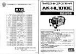
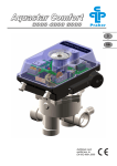
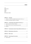
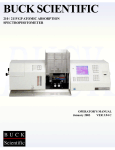
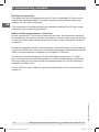
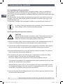
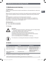
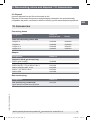
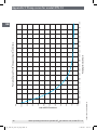
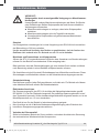
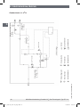
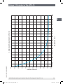
Operating instructions
Betriebsanleitung
Portable SF6 gas transfer unit, model GTU-10
GB
Portables SF6-Gas-Transfergerät, Typ GTU-10
D
Portable SF6 gas transfer unit, model GTU-10
OI_14051107_GTU-10_GB_D.indd 1
13.06.2013 11:28:12
D Betriebsanleitung Typ GTU-10
Page
3 - 20
Seite
21 - 39
© 2013 WIKA Alexander Wiegand SE & Co. KG
All rights reserved. / Alle Rechte vorbehalten.
WIKA® is a registered trademark in various countries.
WIKA® ist eine geschützte Marke in verschiedenen Ländern.
Prior to starting any work, read the operating instructions!
Keep for later use!
Vor Beginn aller Arbeiten Betriebsanleitung lesen!
Zum späteren Gebrauch aufbewahren!
2
OI_14051107_GTU-10_GB_D.indd 2
WIKA operating instructions portable SF6 gas transfer unit, model GTU10
14051107.01 06/2013 GB/D
GB Operating instructions model GTU-10
13.06.2013 11:28:12
Contents
Contents
14051107.01 06/2013 GB/D
GB
1.
General information
4
2.
Safety
5
3.
Specifications
9
4.
Design and function
9
5.
Transport, packaging and storage
9
6.
Commissioning, operation
10
7.
Maintenance and cleaning
17
8.
Faults
17
9.
Dismounting, return and disposal
18
10.
Accessories
19
Appendix 1: EC Declaration of conformity model GTU-10
38
Appendix 2: Pump curve for model GTU-10
20
WIKA operating instructions portable SF6 gas transfer unit, model GTU-10
OI_14051107_GTU-10_GB_D.indd 3
3
13.06.2013 11:28:12
1. General information
1. General information
■■ The digital SF6 gas transfer unit described in the operating instructions has been
designed and manufactured using state-of-the-art technology. All components
are subject to stringent quality and environmental criteria during production. Our
management systems are certified to ISO 9001 and ISO 14001.
GB
■■ These operating instructions contain important information on handling the instru-
ment. Working safely requires that all safety instructions and work instructions are
observed.
■■ Observe the relevant local accident prevention regulations and general safety regula-
tions for the instrument's range of use.
■■ The operating instructions are part of the product and must be kept in the immediate
vicinity of the instrument and readily accessible to skilled personnel at any time.
■■ Skilled personnel must have carefully read and understood the operating instructions
prior to beginning any work.
■■ The manufacturer's liability is void in the case of any damage caused by using the
product contrary to its intended use, non-compliance with these operating instructions, assignment of insufficiently qualified skilled personnel or unauthorised modifications to the instrument.
■■ The general terms and conditions contained in the sales documentation shall apply.
■■ Subject to technical modifications.
- Internet address:
- Relevant data sheet:
- Application consultant:
4
OI_14051107_GTU-10_GB_D.indd 4
www.wika.de/sf6, www.wika.com/sf6
SP 63.07
Tel.:
(+49) 9372/132-8971
E-mail: [email protected]
WIKA operating instructions portable SF6 gas transfer unit, model GTU-10
14051107.01 06/2013 GB/D
■■ Further information:
13.06.2013 11:28:12
1. General information / 2. Safety
Explanation of symbols
WARNING!
... indicates a potentially dangerous situation that can result in serious
injury or death, if not avoided.
GB
CAUTION!
... indicates a potentially dangerous situation that can result in light
injuries or damage to equipment or the environment, if not avoided.
DANGER!
... identifies hazards caused by electric power. Should the safety instructions not be observed, there is a risk of serious or fatal injury.
Information
... points out useful tips, recommendations and information for efficient
and trouble-free operation.
2. Safety
WARNING!
Before installation, commissioning and operation, ensure that the
portable SF6 gas transfer unit and the gas compartments and connecting
parts connected to it comply to the permissible pressure ranges and
power supplies. Non-observance can result in serious injury and/or
damage to the equipment.
14051107.01 06/2013 GB/D
Further important safety instructions can be found in the individual
chapters of these operating instructions.
2.1 Intended use
The model GTU-10 portable SF6 gas transfer unit serves to pump SF6 gas across from
one gas compartment to another. The unit should only be operated in a dry environment
and in an upright position.
The instrument has been designed and built solely for the intended use described here,
and may only be used accordingly.
WIKA operating instructions portable SF6 gas transfer unit, model GTU-10
OI_14051107_GTU-10_GB_D.indd 5
5
13.06.2013 11:28:12
2. Safety
GB
The technical specifications contained in these operating instructions must be
observed. Improper handling or operation of the instrument outside of its technical
specifications requires the instrument to be taken out of service immediately and
inspected by an authorised WIKA service engineer.
Handle the SF6 gas transfer unit with the required care (protect from humidity, impacts,
strong magnetic fields, static electricity and extreme temperatures, do not insert any
objects into the instrument or its openings). Plugs and sockets must be protected from
contamination.
If the instrument is transported from a cold into a warm environment, the formation of
condensation may result in instrument malfunction. Before putting it back into operation,
wait for the instrument temperature and the room temperature to equalise.
The manufacturer shall not be liable for claims of any type based on operation contrary
to the intended use.
2.2 Personnel qualification
WARNING!
Risk of injury should qualification be insufficient!
Improper handling can result in considerable injury and damage to equipment.
The activities described in these operating instructions may only be
carried out by skilled personnel who have the qualifications described
below.
Skilled personnel
Skilled personnel are understood to be personnel who, based on their technical training,
knowledge of measurement and control technology and on their experience and knowledge of country-specific regulations, current standards and directives, are capable of
carrying out the work described and independently recognising potential hazards.
6
OI_14051107_GTU-10_GB_D.indd 6
WIKA operating instructions portable SF6 gas transfer unit, model GTU-10
14051107.01 06/2013 GB/D
2.3 Additional safety instructions for use in switchgear
The plant operator must ensure that the handling of SF6 gas is only carried out by a
qualified company or by qualified persons which have been specially trained in accordance with IEC 61634, section 4.3.1 or IEC 60480, section 10.3.1.
13.06.2013 11:28:12
2. Safety
Valid standards and guidelines for SF6 gas
Installation, assembly, commissioning:
BGI 753 (SF6 plant and equipment in Germany)
IEC 61634 (Handling of SF6 gas)
IEC 60376 (new SF6 gas, technical SF6 gas)
IEC 60480 (used SF6 gas)
CIGRE report 276, 2005 (Practial SF6 gas handling instructions)
■■
■■
■■
■■
■■
GB
Leaks during operation:
■■ IEC 60376 (new SF6 gas, technical SF6 gas)
■■ IEC 60480 (used SF6 gas)
■■ CIGRE 2002 ("SF6 gas in the electrical industry")
Repair work and maintenance:
IEC 61634 (Use and handling of SF6 gas in high-voltage switchgear and controlgear)
CIGRE 1991 (handling of the SF6 gas)
CIGRE report 276, 2005 (Practical SF6 gas handling instructions)
CIGRE report 163, 2000 (Guide for SF6 gas mixtures)
■■
■■
■■
■■
SF6 is a colourless and odourless, chemically neutral, inert and not
inflammable gas which is approx. five times heavier than air, not toxic and
not harmful to the ozone layer.
Detailed information is given in IEC 60376 and IEC 61634.
2.4 Personal protective equipment
The personal protective equipment is designed to protect the skilled personnel from
hazards that could impair their safety or health during work. When carrying out the
various tasks on and with the instrument, the skilled personnel must wear personal
protective equipment.
Follow the instructions, displayed in the work area, regarding personal protective equipment!
The required personal protective equipment must be provided by the operating company.
14051107.01 06/2013 GB/D
Wear safety goggles!
Protect eyes from flying particles and liquid splashes.
Safety goggles to EN 166, Class 2.
Wear protective gloves!
Protect hands from friction, abrasion, cuts or deep injuries and also from
contact with hot or cold surfaces.
WIKA operating instructions portable SF6 gas transfer unit, model GTU-10
OI_14051107_GTU-10_GB_D.indd 7
7
13.06.2013 11:28:13
2. Safety
2.5 Special hazards
WARNING!
Risk of injury due to pneumatic energy
Pneumatic energy can lead to serious injury.
Pneumatically operated components can move unexpectedly.
With damaged individual components, highly pressurised air can escape
and cause eye injuries, for example.
■■ Before starting any work on the machine, it must first be depressurised.
Be careful of the accumulator, and ensure it is fully discharged.
■■ Do not alter the pressure settings above the maximum permissible
levels.
GB
2.6 Labelling, safety marking
Product label (example with gas flow rate of 1.1 m3/h)
Model
Serial number
Output pressure
Speed
Power supply
Power
Fuse
Weight
Date of manufacture
Ingress protection
Explanation of symbols
Before mounting and commissioning the instrument, ensure you read
the operating instructions!
CE, Communauté Européenne
Instruments bearing this mark comply with the relevant European directives.
8
OI_14051107_GTU-10_GB_D.indd 8
WIKA operating instructions portable SF6 gas transfer unit, model GTU-10
14051107.01 06/2013 GB/D
If the serial number becomes illegible due to mechanical damage or overpainting, traceability will no longer be possible.
13.06.2013 11:28:13
3. Specifications / 4. Design and function / 5. Transport, ...
3. Specifications
Gas flow rate:
Maximum pressure:
Pressure reducer, outlet pressure:
Voltage supply:
Operating temperature:
Weight:
Ingress protection:
1.1 m3/h (Option: 1.8 m3/h)
40 bar abs.
0 ... 16 bar
AC 230 V, 50 Hz (Option: AC 115 V, 60 Hz)
Fuse with 10 A, slow
5 ... 40 °C
35 kg (with 1.8 m3/h)
30 kg (with 1.1 m3/h)
IP 20
GB
For further specifications see WIKA data sheet SP 63.07 and the order documentation.
4. Design and function
4.1 Short description
With the GTU-10, the user has the option of a pressure-reduced output to fill a gas
chamber with a preset pressure. From this output, the outlet pressure can be set between
0 ... 16 bar.
If, however, the unreduced output is connected, the GTU-10 has the capability to
compress the gas in the vessel to a maximum of 40 bar, and then automatically switch
off. Thus, the GTU-10 gas transfer unit can liquefy SF6 gas to reduce volume.
4.2 Scope of delivery
Cross-check scope of delivery with delivery note.
5. Transport, packaging and storage
14051107.01 06/2013 GB/D
5.1 Transport
Check the portable SF6 gas transfer unit for any damage that may have been caused by
transport. Obvious damage must be reported immediately.
Only move the unit using the appropriate materials handling equipment e.g. trolley.
Operation of the unit during transport is not permitted.
During any transport, the unit should be secured in accordance with local load regulations. The applicable local safety regulations should be complied with.
WIKA operating instructions portable SF6 gas transfer unit, model GTU-10
OI_14051107_GTU-10_GB_D.indd 9
9
13.06.2013 11:28:13
5. Transport, packaging ... / 6. Commissioning, operation
GB
5.2 Packaging
Do not remove packaging until just before mounting.
Keep the packaging as it will provide optimum protection during transport (e.g. change
in installation site, sending for repair).
5.3 Storage
■■ Only store the portable SF6 gas transfer unit in an upright position.
■■ The instrument should only be lifted using the transport handles.
Permissible conditions at the place of storage:
■■ Storage temperature: -20 ... +60 °C
Avoid exposure to the following factors:
■■ Direct sunlight or proximity to hot objects
■■ Mechanical vibration, mechanical shock (putting it down hard)
■■ Soot, vapour, dust and corrosive gases
■■ Potentially explosive environments, flammable atmospheres
6. Commissioning, operation
CAUTION!
Prior to commissioning, the GTU-10 must be subjected to a visual inspection. The housing should not be corroded and not be opened, so that the
compressor can be started. Operating the instrument without the metal
cladding is prohibited. Only use the instrument if it is in perfect condition
with respect to safety. The GTU-10 has undergone a complete functional
test in the factory and been filled with dry nitrogen to a transport pressure
of approx. 1.2 bar abs. before delivery.
To check the leak-tightness of the connection components and hoses, an
SF6 gas leak detector should be used (e.g. model GIR-10).
CAUTION!
When using gas cylinders, the valve must be protected by a safety valve.
Furthermore, the safe standing of the gas cylinder must be ensured. Use
only approved adapters, hoses and fittings for the connected cylinder
types. There is a risk of accidents when using incorrect equipment.
It is important to be aware that up to 40 bar abs. can be present at
the unreduced outlet. This connection is not suitable for the filling of
equipment that has not been designed for at least 40 bar abs.
10
OI_14051107_GTU-10_GB_D.indd 10
WIKA operating instructions portable SF6 gas transfer unit, model GTU-10
14051107.01 06/2013 GB/D
In the event of any leakage from the lines carrying SF6 gas, the system
must be stopped immediately and the leaks must be eliminated by qualified personnel.
13.06.2013 11:28:13
6. Commissioning, operation
CAUTION!
Danger of tripping caused by improper routing of machine connections
Improperly installed machine connections such as cables, hoses or
pipelines can create tripping hazards, and can cause serious injury.
■■ Route the machine connections so that no tripping sources are
present.
■■ Do not use machine connections to assist carrying.
■■ Mark unavoidable tripping sources with yellow and black marker tape.
GB
Location
To prevent the risk of falling, work in an environment in accordance with EN12464 with
sufficient lighting, ≥ 300 lx.
To ensure adequate ventilation of the instrument, the outlet of the fan must not be
obstructed. Ensure a min. clearance of 30 cm.
Mounting and disassembly of components
All hoses or fittings and threaded connections connected to the GTU-10 must be
designed for operation of at least 50 bar.
Please be aware that the hose lines may be under high pressure and should be vented
into a tank after use.
The connections are sealed with plastic protective caps or adhesive foil. These protective caps and the adhesive foils must be removed before commissioning.
Protective system
The housing must, at all times, be closed and intact. Any operation with open or defective housing will void the operating licence.
Electrical connection
The power supply for the GTU-10 is made via male rubber connector in accordance to
IEC 60320 / C14. The permissible voltage range is indicated on the rating plate. Should
the customer's own power cable be used, it must have a minimum cross-section of
1.5 mm2.
14051107.01 06/2013 GB/D
The unit is only suitable for use in industrial environments.
There should be no connection to the public low-voltage supply without permission from
the power supply company concerned.
Behaviour on power loss
If the power should fail during operation, the electrical control system will prevent the
automatic restart of the compressor.
WIKA operating instructions portable SF6 gas transfer unit, model GTU-10
OI_14051107_GTU-10_GB_D.indd 11
11
13.06.2013 11:28:13
6. Commissioning, operation
GB
Ensuring the gas quality
The system may only be operated with pure SF6 gas. Contaminated SF6 gas must be
cleaned with suitable pre-filters. The quality of the gas can be checked using a gas
analyser, e.g. GA11 SF6-Q-Analyser.
If the compressor is contaminated with decomposition products from SF6 gas, proper
functioning can no longer be guaranteed.
Switch-off with gauge pressure > 40 bar abs.
Should a pressure of > 40 bar abs. be present at the outlet, the compressor will switch
off automatically. The cause could be a full cylinder or a closed valve on the gas cylinder.
The pressure at the outlet must drop below 40 bar abs. in order to be able to restart the
compressor.
Should the compressor not turn off automatically, a mechanical safety valve will open at
a pressure of 50 bar abs.. In this case, shut down the compressor immediately and send
it back to the manufacturer for inspection (see chapter 9.2 “Returns”).
The volume of the pressurised parts of the small-capacity compressor is 1.2 litres.
Due to the small volume and the low pressure, no environmental damage is produced.
With any heating up of the gas and the associated pressure rise, the over-pressure is
reduced via a safety valve.
12
OI_14051107_GTU-10_GB_D.indd 12
WIKA operating instructions portable SF6 gas transfer unit, model GTU-10
14051107.01 06/2013 GB/D
On every GTU-10, prior to delivery, a pressure test with switch-off on over-pressure is
carried out.
13.06.2013 11:28:13
14051107.01 06/2013 GB/D
WIKA operating instructions portable SF6 gas transfer unit, model GTU-10
OI_14051107_GTU-10_GB_D.indd 13
3-way valve
WIKA valve
Pressure reducer
Compressor
Pressure display
Safety valve
Cooler
Pressure switch
AC 230 V, 50/60 Hz
pset = 50 bar
Non-return valve
Inlet pressure
-1 ... 11 bar
-15 ... 160 psi
pset = 10.3 bar
Output pressure
0 ... 60 bar
0 ... 1,000 psi
Outlet pressure pressure reducer
0 ... 16 bar
0 ... 300 psi
6. Commissioning, operation
6.1 Functional diagram
Gas flow rate 1.8 m3/h
GB
13
13.06.2013 11:28:15
14
OI_14051107_GTU-10_GB_D.indd 14
WIKA operating instructions portable SF6 gas transfer unit, model GTU-10
14051107.01 06/2013 GB/D
Cooler
Pressure reducer
WIKA valve
Pressure switch
Compressor
3-way valve
Pressure display
Safety valve
AC 230 V, 50/60 Hz
pset = 50 bar
Non-return valve
Inlet pressure
-1 ... 11 bar
-15 ... 160 psi
pset = 10.3 bar
Output pressure
0 ... 60 bar
0 ... 1,000 psi
Outlet pressure pressure reducer
0 ... 16 bar
0 ... 300 psi
6. Commissioning, operation
Gas flow rate 1.1 m3/h
GB
13.06.2013 11:28:16
6. Commissioning, operation
6.2 Instrument construction
1
3
4
5
7
6
2
8
9
10
1
Overpressure warning lamp
2
On/Off switch
3
Pressure display, inlet pressure
4
Operating hours counter
5
Pressure reducer
6
Pressure display, output pressure reducer
GB
7
Pressure display output pressure
8
Valve coupling, input
9
Valve coupling, output pressure reducer
10 Valve coupling, output
6.3 Pumping out an SF6 gas compartment into a gas cylinder
1) Connect the unreduced or reduced outlet with the gas compartment to be filled. Only
one of the two outlets should be connected.
Before switching on the GTU-10, the connection to the gas compartments should
be checked for leakage at the inlet and outlet. A leakage detector for SF6 gas (e.g.
model GIR-10) should be used to test the connections.
2) Press the Start button in order to switch the compressor on. The gas will be pumped
from the inlet to the outlet.
If the tank pressure at the inlet is higher than that at the outlet, a pressure equalisation will occur.
Example: 7 bar abs. in inlet tank and 1 bar abs. on the outlet side will generate a
lower equalised pressure, e.g. 3 bar abs., in the connected system, depending on the
volume ratio.
14051107.01 06/2013 GB/D
For the pump curve, see page 21
3) After reaching the desired filling pressure in the tank being pumped out, the unit
should again be switched off and all connections disconnected.
WIKA operating instructions portable SF6 gas transfer unit, model GTU-10
OI_14051107_GTU-10_GB_D.indd 15
15
13.06.2013 11:28:17
6. Commissioning, operation
GB
6.4 Consolidating SF6 gas cylinders
When filling SF6 gas compartments by using gas cylinders, there is a possibility of
considerable amounts of residual SF6 gas remaining in the cylinders. For this, the
GTU-10 can be used to generate a completely filled gas cylinder from several part-filled
gas cylinders.
For this purpose, the part-filled gas cylinders are connected, one after the other and
gas-tight, to the inlet, and the gas cylinder to be filled is connected, gas-tight, to the
unreduced outlet (10).
The process of the gas transfer should be carried out as described in chapter 6.3.
In order to fill the gas cylinders to the maximum, they should be cooled
during filling in order to increase the filling quantity.
6.5 SF6 gas filling with pressure reduction
CAUTION!
Ensure that the reduced connection is used. The unreduced outlet can
generate pressures that are significantly higher than required, and to
which the connected tank might possibly not be suited.
1) Before starting the filling, set the pressure reducer to the smallest pressure step. To
do this, turn the pressure reducer anti-clockwise all the way to the stop.
2) Connect the unreduced outlet with the gas compartment to be filled. After opening
the gas cylinder valve, the pre-pressure is available at the pressure reducer.
3) Set the desired pressure by turning the pressure reducer clockwise. The pressure
value is read from the pressure display (6).
4) By connecting the outlet valve with the gas compartment to be filled, the filling
process is started. The gas flows via the pressure reducer.
During the filling process, the pressure on the pressure display rises (6).
Before switching on the GTU-10, the connection to the gas compartments should
be checked for leakage at the inlet and outlet. A leakage detector for SF6 gas (e.g.
model GIR-10) should be used to test the connections.
5) After reaching the desired filling pressure, the unit should again be switched off and
all connections disconnected.
16
OI_14051107_GTU-10_GB_D.indd 16
WIKA operating instructions portable SF6 gas transfer unit, model GTU-10
14051107.01 06/2013 GB/D
If the pressure equalisation is completed and the desired pressure has not yet been
reached, the compressor can be started.
13.06.2013 11:28:17
7. Maintenance and cleaning / 8. Faults
7. Maintenance and cleaning
7.1 Maintenance
Repairs must only be carried out by the manufacturer or the manufacturer's authorised
personnel.
GB
Before all work is carried out on the machine, the machine must be switched off and the
mains connector pulled out. Valves must be properly vented before any maintenance
work.
A cooling phase of a minimum of 10 minutes must be observed.
The electrical connection is made via a male rubber connector in accordancte to
IEC 60320 / C14, the isolation from the mains supply is achieved by pulling out the
female rubber connector acc. to. IEC 60320 / C13.
Service interval
■■ 1.8 m3/h: after 500 hours operation
■■ 1.1 m3/h: after 100 hours operation
7.2 Cleaning
CAUTION!
■■ Before cleaning the instrument, disconnect it from the voltage supply
and leave it switched off for at least 10 minutes.
■■ Clean the instrument with a moist cloth.
■■ Only air-clean the opened unit using compressed air.
■■ Electrical connections must not come into contact with moisture.
■■ Do not use aggressive cleaning agents.
■■ Do not use any pointed or hard objects for cleaning.
For information on returning the instrument see chapter 9.2 “Returns”.
14051107.01 06/2013 GB/D
8. Faults
Faults
Causes
Measures
Compressor will not start
Gauge pressure > 40 bar abs.
Safety valve is actuated
Pressure switch has failed
Noisy operation of the
compressor
Compressor wear
Relieve the outlet pressure,
empty the tank at the outlet
Send the unit back to the
manufacturer for testing (see
chapter 9.2 "Returns")
Contact service.
If complaint is unjustified, the handling costs will be charged.
WIKA operating instructions portable SF6 gas transfer unit, model GTU-10
OI_14051107_GTU-10_GB_D.indd 17
17
13.06.2013 11:28:17
8. Faults / 9. Dismounting, return and disposal
CAUTION!
If faults cannot be eliminated by means of the measures listed above,
the instrument must be shut down immediately, it must be ensured that
pressure is no longer present, and it must be prevented from being
inadvertently put back into service.
In this case, contact the manufacturer.
If a return is needed, please follow the instructions given in chapter 9.2
“Returns”.
GB
9. Dismounting, return and disposal
WARNING!
Residual media in the portable SF6 gas transfer unit can result in a risk to
personnel, the environment and equipment.
Take sufficient precautionary measures.
9.1 Dismounting
DANGER!
Danger of death caused by electric current
Prior to dismantling the instrument, disconnect it properly from the mains.
WARNING!
Contains pressurised gas, that can explode if heated. Only dismantle the
instrument in a well-ventilated location.
Before dismantling the instrument, evacuate the gas filling.
9.2 Returns
When returning the instrument, use the original packaging or a suitable transport
package.
Information on returns can be found under the heading "Service" on our
local website.
18
OI_14051107_GTU-10_GB_D.indd 18
WIKA operating instructions portable SF6 gas transfer unit, model GTU-10
14051107.01 06/2013 GB/D
WARNING!
Strictly observe the following when shipping the instrument:
All instruments delivered to WIKA must be free from any kind of hazardous substances (acids, bases, solutions, etc.).
13.06.2013 11:28:17
9. Dismounting, return and disposal / 10. Accessories
9.3 Disposal
Incorrect disposal can put the environment at risk.
Dispose of instrument components and packaging materials in an environmentally
compatible way and in accordance with the country-specific waste disposal regulations.
GB
10. Accessories
Connecting hoses
Designation
Order no.
Stainless steel
Rubber
Hose with self-sealing valves, DN8
Length 3 m
Length 6 m
Length 12 m
Length 15 m
14064922
14064923
14064924
14064927
14064928
14064929
14064931
14064933
Adapter
Designation
Adapter for GA45 gas recovery bag
DN8 to quick coupling
Adapter for gas cylinder
DN8 to W21.8 x 1/14" per DIN 477 No. 6
DN8 to CGA590 0.960" 15/16"
DN8 to 1" per DIN 477 No. 8
DN8 to G5/8"
Order no.
14068883
14074524
14074523
14074521
14074525
Gas recovery bag
Designation
14051107.01 06/2013 GB/D
Gas recovery bag, model GA45
Specifications see data sheet SP 62.08
Order no.
14013015
WIKA operating instructions portable SF6 gas transfer unit, model GTU-10
OI_14051107_GTU-10_GB_D.indd 19
19
13.06.2013 11:28:17
20
OI_14051107_GTU-10_GB_D.indd 20
0,0
1,0
2,0
3,0
4,0
5,0
6,0
7,0
8,0
9,0
0:00
0:05
0:10
0:15
0:20
0:25
0:35
0:40
0:45
0:50
[t] h:min
in h:min
PumpingPumpzeit
time [t] in
0:30
0:55
1:00
1:05
1:10
1:15
1:20
1:25
GB
WIKA operating instructions portable SF6 gas transfer unit, model GTU-10
14051107.01 06/2013 GB/D
Druck
[p]bar
in bar
abs.
Pressure
[p] in
abs.
10,0
11,0
Abpumpkurve
90 Liter
Pump down
graph for 90Gasraumvolumen
litre gas compartment
volume
Appendix 2: Pump curve for model GTU-10
13.06.2013 11:28:17
Inhalt
14051107.01 06/2013 GB/D
Inhalt
1.
Allgemeines
22
2.
Sicherheit
23
3.
Technische Daten
27
4.
Aufbau und Funktion
27
5.
Transport, Verpackung und Lagerung
27
6.
Inbetriebnahme, Betrieb
28
7.
Wartung und Reinigung
35
8.
Störungen
35
9.
Demontage, Rücksendung und Entsorgung
36
10.
Zubehör
37
Anlage 1: EG-Konformitätserklärung Typ GTU-10
38
Anlage 2: Pumpkurve Typ GTU-10
39
WIKA Betriebsanleitung Portables SF6-Gas-Transfergerät, Typ GTU-10
OI_14051107_GTU-10_GB_D.indd 21
D
21
13.06.2013 11:28:17
1. Allgemeines
1. Allgemeines
■■ Das in der Betriebsanleitung beschriebene SF6-Gas-Transfergerät wird nach dem
D
aktuellen Stand der Technik konstruiert und gefertigt.
Alle Komponenten unterliegen während der Fertigung strengen Qualitäts- und
Umweltkriterien. Unsere Managementsysteme sind nach ISO 9001 und ISO 14001
zertifiziert.
■■ Diese Betriebsanleitung gibt wichtige Hinweise zum Umgang mit dem Gerät. Voraus-
setzung für sicheres Arbeiten ist die Einhaltung aller angegebenen Sicherheitshinweise und Handlungsanweisungen.
■■ Die für den Einsatzbereich des Gerätes geltenden örtlichen Unfallverhütungsvor-
schriften und allgemeinen Sicherheitsbestimmungen einhalten.
■■ Die Betriebsanleitung ist Produktbestandteil und muss in unmittelbarer Nähe des
Gerätes für das Fachpersonal jederzeit zugänglich aufbewahrt werden.
■■ Das Fachpersonal muss die Betriebsanleitung vor Beginn aller Arbeiten sorgfältig
durchgelesen und verstanden haben.
■■ Die Haftung des Herstellers erlischt bei Schäden durch bestimmungswidrige Verwen-
dung, Nichtbeachten dieser Betriebsanleitung, Einsatz ungenügend qualifizierten
Fachpersonals sowie eigenmächtiger Veränderung am Gerät.
■■ Es gelten die allgemeinen Geschäftsbedingungen in den Verkaufsunterlagen.
■■ Technische Änderungen vorbehalten.
- Internet-Adresse:
- zugehöriges Datenblatt:
- Anwendungsberater:
22
OI_14051107_GTU-10_GB_D.indd 22
www.wika.de/sf6, www.wika.com/sf6
SP 63.07
Tel.:
(+49) 9372/132-8971
E-Mail: [email protected]
WIKA Betriebsanleitung Portables SF6-Gas-Transfergerät, Typ GTU-10
14051107.01 06/2013 GB/D
■■ Weitere Informationen:
13.06.2013 11:28:17
1. Allgemeines / 2. Sicherheit
Symbolerklärung
WARNUNG!
… weist auf eine möglicherweise gefährliche Situation hin, die zum Tod
oder zu schweren Verletzungen führen kann, wenn sie nicht gemieden
wird.
VORSICHT!
… weist auf eine möglicherweise gefährliche Situation hin, die zu geringfügigen oder leichten Verletzungen bzw. Sach- und Umweltschäden
führen kann, wenn sie nicht gemieden wird.
D
GEFAHR!
… kennzeichnet Gefährdungen durch elektrischen Strom. Bei Nichtbeachtung der Sicherheitshinweise besteht die Gefahr schwerer oder
tödlicher Verletzungen.
Information
… hebt nützliche Tipps und Empfehlungen sowie Informationen für einen
effizienten und störungsfreien Betrieb hervor.
2. Sicherheit
WARNUNG!
Vor Montage, Inbetriebnahme und Betrieb sicherstellen, dass das
portable SF6-Gastransfergerät und die daran angeschlossenen
Gasräume und Anschlussteile den zulässigen Druckbereichen und
Versorgungsspannungen entsprechen. Bei Nichtbeachten können
schwere Körperverletzungen und/oder Sachschäden auftreten.
14051107.01 06/2013 GB/D
Weitere wichtige Sicherheitshinweise befinden sich in den einzelnen
Kapiteln dieser Betriebsanleitung.
2.1 Bestimmungsgemäße Verwendung
Das portable SF6-Gas-Transfergerät Typ GTU-10 dient dem Umpumpen von SF6-Gas
von einem Gasraum in einen anderen. Das Gerät darf nur in trockener Umgebung und
in aufrechter Position betrieben werden.
Das Gerät ist ausschließlich für den hier beschriebenen bestimmungsgemäßen Verwendungszweck konzipiert und konstruiert und darf nur dementsprechend verwendet werden.
WIKA Betriebsanleitung Portables SF6-Gas-Transfergerät, Typ GTU-10
OI_14051107_GTU-10_GB_D.indd 23
23
13.06.2013 11:28:17
2. Sicherheit
Die technischen Spezifikationen in dieser Betriebsanleitung sind einzuhalten. Eine
unsachgemäße Handhabung oder ein Betreiben des Gerätes außerhalb der technischen Spezifikationen macht die sofortige Stilllegung und Überprüfung durch einen
autorisierten WIKA-Servicemitarbeiter erforderlich.
D
Portables SF6-Gas-Transfergerät mit erforderlicher Sorgfalt behandeln (vor Nässe,
Stößen, starken Magnetfeldern, statischer Elektrizität und extremen Temperaturen
schützen, keine Gegenstände in das Gerät bzw. Öffnungen einführen). Stecker und
Buchsen vor Verschmutzung schützen.
Wird das Gerät von einer kalten in eine warme Umgebung transportiert, so kann durch
Kondensatbildung eine Störung der Gerätefunktion eintreten. Vor einer erneuten
Inbetriebnahme die Angleichung der Gerätetemperatur an die Raumtemperatur
abwarten.
Ansprüche jeglicher Art aufgrund von nicht bestimmungsgemäßer Verwendung sind
ausgeschlossen.
2.2 Personalqualifikation
WARNUNG!
Verletzungsgefahr bei unzureichender Qualifikation!
Unsachgemäßer Umgang kann zu erheblichen Personen- und Sachschäden führen.
Die in dieser Betriebsanleitung beschriebenen Tätigkeiten nur durch
Fachpersonal nachfolgend beschriebener Qualifikation durchführen
lassen.
Fachpersonal
Das Fachpersonal ist aufgrund seiner fachlichen Ausbildung, seiner Kenntnisse der
Mess- und Regelungstechnik und seiner Erfahrungen sowie Kenntnis der landesspezifischen Vorschriften, geltenden Normen und Richtlinien in der Lage, die beschriebenen
Arbeiten auszuführen und mögliche Gefahren selbstständig zu erkennen.
24
OI_14051107_GTU-10_GB_D.indd 24
WIKA Betriebsanleitung Portables SF6-Gas-Transfergerät, Typ GTU-10
14051107.01 06/2013 GB/D
2.3 Zusätzliche Sicherheitshinweise für die Verwendung in Schaltanlagen
Der Betreiber muss sicherstellen, dass die Handhabung von SF6-Gas durch ein hierzu
qualifiziertes Unternehmen oder von gemäß IEC 61634 Abschnitt 4.3.1 bzw. IEC 60480
Abschnitt 10.3.1 geschulten Mitarbeitern durchgeführt wird.
13.06.2013 11:28:17
2. Sicherheit
Geltende Normen und Richtlinien für SF6-Gas
Installation, Errichtung, Inbetriebnahme:
■■ BGI 753 (SF6-Anlagen und Betriebsmittel in Deutschland)
■■ IEC 61634 (Handhabung von SF6 gas)
■■ IEC 60376 (neues SF6 gas, technisches SF6 gas)
■■ IEC 60480 (gebrauchtes SF6 gas)
■■ CIGRE report 276, 2005 (Practial SF6 gas handling instructions)
D
Leckagen während des Betriebs:
■■ IEC 60376 (neues SF6-Gas, technisches SF6-Gas)
■■ IEC 60480 (gebrauchtes SF6-Gas)
■■ CIGRE 2002 („SF6 gas in the electrical industry“)
Reparaturarbeiten und Wartung:
IEC 61634 (Use and handling of SF6 gas in high-voltage switchgear and controlgear)
CIGRE 1991 (Handhabung von SF6-Gas)
CIGRE report 276, 2005 (Practical SF6 gas handling instructions)
CIGRE report 163, 2000 (Guide for SF6 gas mixtures)
■■
■■
■■
■■
SF6-Gas ist farb- und geruchlos, chemisch neutral, inert, nicht entflammbar und etwa fünfmal schwerer als Luft, nicht toxisch und nicht ozonschädigend.
Detaillierte Angaben befinden sich in der IEC 60376 und IEC 61634.
2.4 Persönliche Schutzausrüstung
Die persönliche Schutzausrüstung dient dazu, das Fachpersonal gegen Gefahren
zu schützen, die dessen Sicherheit oder Gesundheit bei der Arbeit beeinträchtigen
könnten. Beim Ausführen der verschiedenen Arbeiten an und mit dem Gerät muss das
Fachpersonal persönliche Schutzausrüstung tragen.
Im Arbeitsbereich angebrachte Hinweise zur persönlichen Schutzausrüstung
befolgen!
14051107.01 06/2013 GB/D
Die erforderliche persönliche Schutzausrüstung muss vom Betreiber zur Verfügung
gestellt werden.
Schutzbrille tragen!
Schutz der Augen vor umherfliegenden Teilen und Flüssigkeitsspritzern.
Schutzbrille nach EN 166, Klasse 2.
Schutzhandschuhe tragen!
Schutz der Hände vor Reibung, Abschürfung, Einstichen oder tieferen
Verletzungen sowie vor Berührung mit heißen oder kalten Oberflächen.
WIKA Betriebsanleitung Portables SF6-Gas-Transfergerät, Typ GTU-10
OI_14051107_GTU-10_GB_D.indd 25
25
13.06.2013 11:28:18
2. Sicherheit
2.5 Besondere Gefahren
WARNUNG!
Verletzungsgefahr durch pneumatische Energien
Pneumatische Energien können schwerste Verletzungen verursachen.
Pneumatisch angetriebene Teile können sich unerwartet bewegen.
Bei Beschädigungen einzelner Bauteile kann Luft unter hohem Druck
austreten und z. B. die Augenschädigen.
■■ Vor Beginn von Arbeiten an der Maschine diese zuerst drucklos
machen. Auf Druckspeicher achten und diesen vollständig entspannen.
■■ Druckeinstellungen nicht über die maximal zulässigen Werte hinaus
verändern.
D
2.6 Beschilderung, Sicherheitskennzeichnungen
Typenschild (Beispiel mit Gasdurchsatz von 1,1 m3/h)
Typ
Seriennummer
Ausgangsdruck
Drehzahl
Hilfsenergie
Leistung
Sicherung
Gewicht
Herstelldatum
Schutzart
Symbolerklärung
Vor Montage und Inbetriebnahme des Gerätes unbedingt die
Betriebsanleitung lesen!
CE, Communauté Européenne
Geräte mit dieser Kennzeichnung stimmen überein mit den zutreffenden
europäischen Richtlinien.
26
OI_14051107_GTU-10_GB_D.indd 26
WIKA Betriebsanleitung Portables SF6-Gas-Transfergerät, Typ GTU-10
14051107.01 06/2013 GB/D
Wird die Seriennummer durch mechanische Beschädigung oder Übermalen unleserlich,
ist eine Rückverfolgbarkeit nicht mehr möglich.
13.06.2013 11:28:18
3. Technische Daten / 4. Aufbau ... / 5. Transport, ...
3. Technische Daten
Gasdurchsatz:
Maximaldruck:
Ausgangsdruck Druckminderer:
Spannungsversorgung:
Betriebstemperatur:
Gewicht:
Schutzart:
1,1 m3/h (Option: 1,8 m3/h)
40 bar abs.
0 ... 16 bar
AC 230 V, 50 Hz (Option: AC 115 V, 60 Hz)
Absicherung mit 10 A, träge
5 ... 40 °C
35 kg (bei 1,8 m3/h)
30 kg (bei 1,1 m3/h)
IP 20
D
Weitere technische Daten siehe WIKA-Datenblatt SP 63.07 und Bestellunterlagen.
4. Aufbau und Funktion
4.1 Kurzbeschreibung
Mit dem GTU-10 hat der Anwender die Wahl über einen druckgeminderten Ausgang
einen Gasraum mit voreingestelltem Druck zu befüllen. An diesem Ausgang können
zwischen 0 ... 16 bar Ausgangsdruck eingestellt werden.
Wird hingegen der ungeminderte Ausgang angeschlossen, ist das GTU-10 in der Lage
das Gas im Behälter bis max. 40bar abs. zu verdichten und schaltet danach automatisch
ab. Damit ist das portable Gastransfergerät GTU-10 in der Lage SF6-Gas platzsparend
zu verflüssigen.
4.2 Lieferumfang
Lieferumfang mit dem Lieferschein abgleichen.
5. Transport, Verpackung und Lagerung
14051107.01 06/2013 GB/D
5.1 Transport
Das portable SF6-Gas-Transfergerät auf eventuell vorhandene Transportschäden untersuchen. Offensichtliche Schäden unverzüglich mitteilen.
Das Gerät nur mit geeigneten Tranportgeräten z. B. Sackkarre transportieren. Ein
Betrieb des Gerätes während des Transports ist unzulässig.
Während des Tranportes ist das Gerät gemäß lokaler Ladungsvorschrift zu befestigen.
Die geltenden lokalen Unfallverhütungsvorschriften sind einzuhalten.
WIKA Betriebsanleitung Portables SF6-Gas-Transfergerät, Typ GTU-10
OI_14051107_GTU-10_GB_D.indd 27
27
13.06.2013 11:28:18
5. Transport, Verpackung ... / 6. Inbetriebnahme, Betrieb
5.2 Verpackung
Verpackung erst unmittelbar vor der Montage entfernen.
Die Verpackung aufbewahren, denn diese bietet bei einem Transport einen optimalen
Schutz (z. B. wechselnder Einbauort, Reparatursendung).
D
5.3 Lagerung
■■ Portables SF6-Gas-Transfergerät nur aufrecht stehend lagern.
■■ Anheben des Gerätes soll ausschließlich über die Transportgriffe erfolgen.
Zulässige Bedingungen am Lagerort:
■■ Lagertemperatur: -20 ... +60 °C
Folgende Einflüsse vermeiden:
■■ Direktes Sonnenlicht oder Nähe zu heißen Gegenständen
■■ Mechanische Vibration, mechanischer Schock (hartes Aufstellen)
■■ Ruß, Dampf, Staub und korrosive Gase
■■ Explosionsgefährdete Umgebung, entzündliche Atmosphären
6. Inbetriebnahme, Betrieb
VORSICHT!
Vor der Inbetriebnahme das GTU-10 optisch prüfen. Das Gehäuse darf
nicht korrodiert und nicht geöffnet sein, damit der Kompressor gestartet
werden kann. Ein Betreiben des Geräts ohne Blechverkleidung ist nicht
gestattet. Das Gerät nur in sicherheitstechnisch einwandfreiem Zustand
einsetzen. Das GTU-10 wurde ab Werk komplett funktionsgeprüft und vor
Auslieferung mit einem Transportdruck von ca. 1,2 bar abs. trockenem
Stickstoff gefüllt.
Zum Überprüfen der Dichtheit von Verbindungsteilen und Schläuchen
sollte ein Lecksuchgerät für SF6-Gas eingesetzt werden (z. B. Typ GIR-10).
VORSICHT!
Bei Verwendung von Gaszylindern ist das Ventil durch einen Ventilschutz
zu sichern. Weiterhin ist der sichere Stand der Gasflasche sicherzustellen. Nur geeignete Anschlussstücke, Schläuche und Armaturen für den
anzuschließenden Flaschentyp verwenden. Unfallgefahr bei Verwendung
nicht geeigneter Betriebsmittel.
Es ist darauf zu achten, das am ungeminderten Ausgang bis zu 40 bar
abs. entstehen können. Dieser Anschluss ist nicht geeignet zum Füllen
von Anlagen die nicht für mindestens 40 bar abs. ausgelegt sind.
28
OI_14051107_GTU-10_GB_D.indd 28
WIKA Betriebsanleitung Portables SF6-Gas-Transfergerät, Typ GTU-10
14051107.01 06/2013 GB/D
Treten Leckagen an den SF6-Gas führenden Leitungen auf, so ist die
Anlage sofort stillzulegen und die Leckagen sind vom Fachpersonal zu
beseitigen.
13.06.2013 11:28:18
6. Inbetriebnahme, Betrieb
VORSICHT!
Stolpergefahr durch unsachgemäße Verlegung von Maschinenverbindungen
Unsachgemäß verlegte Maschinenverbindungen wie Kabel, Schläuche
oder Rohrleitungen stellen Stolperquellen dar und können erhebliche
Verletzungen verursachen.
■■ Maschinenverbindungen so verlegen, dass keine Stolperquellen
entstehen.
■■ Maschinenverbindungen nicht als Tragehilfe verwenden
■■ Unumgängliche Stolperstellen mit gelbschwarzem Markierband
kennzeichnen.
D
Standort
Um Sturzgefahren vorzubeugen ist in einer Umgebung nach EN12464 mit ausreichender Beleuchtung ≥ 300 lx zu arbeiten.
Um die ausreichende Ventilation des Gerätes zu gewährleisten, darf der Auslass des
Gebläses nicht verdeckt sein. Ein Abstand von min. 30 cm ist einhalten.
Montieren und Demontieren von Komponenten
Alle an das GTU-10 angeschlossenen Schläuche bzw. Armaturen und Verschraubungen
müssen für den Betrieb von mindestens 50 bar ausgelegt sein.
Bitte beachten, dass die Schlauchleitungen ggf. unter hohem Druck stehen und diese
nach Benutzung wieder in einen Behälter entspannt werden müssen.
Die Anschlüsse sind mit Kunststoff-Schutzkappen bzw. Klebefolie verschlossen. Diese
Schutzkappen und Klebefolien müssen vor der Inbetriebnahme abgezogen werden.
Schutzeinrichtung
Das Gehäuse muss zu jeder Zeit geschlossen und intakt sein. Für Betrieb mit offenem
oder defektem Gehäuse erlischt die Betriebserlaubnis.
14051107.01 06/2013 GB/D
Elektrischer Anschluss
Die Stromversorgung für das GTU-10 wird über die Kaltgeräteeinbaustecker gemäß
IEC-60320 / C14 an der Rückseite hergestellt. Der zulässige Spannungsbereich ist auf
dem Typenschild vermerkt. Sollten kundenseitige Netzkabel eingesetzt werden, so ist ein
Mindestquerschnitt von 1,5 mm2 einzuhalten.
Das Gerät ist nur für den Betrieb in Industrieumgebung geeignet.
Kein Anschluss an die öffentliche Niederspannungsversorgung ohne Erlaubnis des
betroffenen Energieversorgungsunternehmens.
Verhalten bei Stromausfall
Sollte bei laufendem Betrieb der Strom ausfallen, verhindert die elektrische Steuerung
den automatischen Wiederanlauf des Kompressors.
WIKA Betriebsanleitung Portables SF6-Gas-Transfergerät, Typ GTU-10
OI_14051107_GTU-10_GB_D.indd 29
29
13.06.2013 11:28:18
6. Inbetriebnahme, Betrieb
Sicherstellung der Gasqualität
Die Anlage darf nur mit reinem SF6-Gas betrieben werden. Verunreinigtes SF6-Gas
muss mit geeigneten Vorfiltern gereinigt werden. Die Gasqualität kann mit einem
Gasanalysegerät z.B. Typ GA11 SF6-Q-Analyser überprüft werden.
D
Wird der Kompressor mit Spaltprodukten von SF6-Gas verunreinigt ist die einwandfreie
Funktion nicht mehr gewährleistet.
Abschaltung bei Überdruck > 40 bar abs.
Sollte am Ausgang ein Druck > 40 bar abs. entstehen, schaltet der Kompressor automatisch ab. Die Ursache kann ein voller Gaszylinder bzw. ein geschlossenes Ventil am
Gaszylinder sein. Damit der Kompressor sich wieder starten lässt, muss der Druck am
Ausgang unter 40 bar abs. sinken.
Sollte der Kompressor nicht automatisch abschalten öffnet sich bei Überdruck von
50 bar abs. ein mechanisches Sicherheitsventil. In diesem Fall den Kompressor sofort
außer Betrieb nehmen und zur Überprüfung an den Hersteller schicken (siehe Kapitel
9.2 „Rücksendung“).
Das Volumen der druckbeaufschlagten Teile des Kleinkompressors beträgt 1,2 Liter.
Durch das kleine Volumen und den geringen Druck ist keine Umweltschädigung
gegeben. Bei einer Erwärmung des Gases und dem damit verbundenen Druckanstieg
wird der Überdruck über ein Sicherheitsventil abgebaut.
30
OI_14051107_GTU-10_GB_D.indd 30
WIKA Betriebsanleitung Portables SF6-Gas-Transfergerät, Typ GTU-10
14051107.01 06/2013 GB/D
An jedem GTU-10 wurde vor Auslieferung eine Druckprüfung mit Abschaltung bei
Überdruck durchgeführt.
13.06.2013 11:28:18
14051107.01 06/2013 GB/D
WIKA Betriebsanleitung Portables SF6-Gas-Transfergerät, Typ GTU-10
OI_14051107_GTU-10_GB_D.indd 31
3-Wege-Ventil
WIKA-Ventil
Druckminderer
Kompressor
Druckanzeige
Sicherheitsventil
Kühler
Druckschalter
AC 230 V, 50/60 Hz
pset = 50 bar
Rückschlagventil
Eingangsdruck
-1 ... 11 bar
-15 ... 160 psi
pset = 10,3 bar
Ausgangsdruck
0 ... 60 bar
0 ... 1.000 psi
Ausgangsdruck Druckminderer
0 ... 16 bar
0 ... 300 psi
6. Inbetriebnahme, Betrieb
6.1 Funktionsschema
Gasdurchsatz 1,8 m3/h
D
31
13.06.2013 11:28:20
32
OI_14051107_GTU-10_GB_D.indd 32
WIKA Betriebsanleitung Portables SF6-Gas-Transfergerät, Typ GTU-10
14051107.01 06/2013 GB/D
Kühler
Druckminderer
WIKA-Ventil
Druckschalter
Kompressor
3-Wege-Ventil
Druckanzeige
Sicherheitsventil
AC 230 V, 50/60 Hz
pset = 50 bar
Rückschlagventil
Eingangsdruck
-1 ... 11 bar
-15 ... 160 psi
pset = 10,3 bar
D
Ausgangsdruck
0 ... 60 bar
0 ... 1.000 psi
Ausgangsdruck Druckminderer
0 ... 16 bar
0 ... 300 psi
6. Inbetriebnahme, Betrieb
Gasdurchsatz 1,1 m3/h
13.06.2013 11:28:22
6. Inbetriebnahme, Betrieb
6.2 Geräteaufbau
1
3
4
5
7
6
2
8
9
10
1
Überdruckwarnlampe
2
Ein-/Ausschalter
3
Druckanzeige Eingangsdruck
4
Betriebsstundenzähler
5
Druckminderer
6
Druckanzeige Ausgang Druckminderer
7
Druckanzeige Ausgangsdruck
8
Ventilkupplung Eingang
9
Ventilkupplung Ausgang Druckminderer
D
10 Ventilkupplung Ausgang
6.3 Abpumpen eines SF6-Gasraumes in einen Gaszylinder
1) Ungeminderten oder geminderten Ausgang mit den zu befüllenden Gasraum verbinden. Es darf nur einer der beiden Ausgänge angeschlossen sein.
Vor Einschalten des GTU-10 die Verbindungen zu den Gasräumen am Eingang und
Ausgang auf Leckagen überprüfen. Zur Prüfung der Dichtheit an den Verbindungen
ist ein Lecksuchgerät für SF6-Gas zu verwenden (z. B. Typ GIR-10).
2) Startknopf betätigen, um den Kompressor einzuschalten. Das Gas wird vom Eingang
zum Ausgang gepumpt.
Ist der Behälterdruck am Eingang höher als der am Ausgang, findet ein Druckausgleich statt.
Beispiel: 7 bar abs. im Eingangsbehälter und 1 bar abs. auf der Ausgangsseite
stellt je nach Volumenverhältnis einen kleineren Ausgleichsdruck z. B. 3 bar abs. im
Verbundsystem her.
14051107.01 06/2013 GB/D
Pumpkurve siehe Seite 41
3) Nach Erreichen des gewünschten Fülldruckes am abzupumpenden Behälter, das
Gerät wieder abschalten und alle Verbindungen lösen.
WIKA Betriebsanleitung Portables SF6-Gas-Transfergerät, Typ GTU-10
OI_14051107_GTU-10_GB_D.indd 33
33
13.06.2013 11:28:22
6. Inbetriebnahme, Betrieb
D
6.4 SF6-Gaszylinder zusammenführen
Bei der Füllung von SF6-Gasräumen mit Hilfe von Gaszylindern bleiben möglicherweise
erhebliche Restmengen von SF6-Gas in den Zylindern zurück. Die GTU-10 kann dazu
genutzt werden aus mehreren teilgefüllten Gaszylindern einen komplett gefüllten
Gaszylinder herzustellen.
Dazu werden nacheinander die teilgefüllten Gaszylinder am Eingang und der zu
füllende Gaszylinder am ungeminderten Ausgang (10) gasdicht angeschlossen.
Der Ablauf des Gastransfers ist wie in Kapitel 6.3 beschrieben durchzuführen.
Für die maximale Füllung von Gaszylindern sollten diese bei Befüllung
gekühlt werden, um die Füllmenge zu erhöhen.
6.5 SF6-Gasfüllung mit Druckminderung
VORSICHT!
Sicherstellen, dass der geminderte Anschluss verwendet wird. Der
ungeminderte Ausgang kann wesentlich höhere Drücke als gefordert
erzeugen, für die das angeschlossenen Behältnis evtl. nicht geeignet ist
1) Vor Beginn der Füllung den Druckminderer auf die kleinste Druckstufe stellen. Dazu
den Druckminderer gegen Uhrzeigersinn bis zum Anschlag drehen.
2) Ungeminderten Ausgang mit den zu befüllenden Gasraum verbinden. Am Druckminderer steht nach Öffnen des Gasflaschenventils der Vordruck an.
3) Den gewünschten Druck durch Drehen des Druckminderers im Uhrzeigersinn einstellen. Den Druckwert über die Druckanzeige (6) ablesen.
4) D
urch Verbinden des Ausgangsventiles mit dem zu füllenden Gasraum wird der
Füllvorgang gestartet. Das Gas strömt über den Druckminderer.
Während des Füllvorganges steigt der Druck an der Druckanzeige (6) an.
Vor Einschalten des GTU-10 die Verbindungen zu den Gasräumen am Eingang und
Ausgang auf Leckagen überprüfen. Zur Prüfung der Dichtheit an den Verbindungen
ist ein Lecksuchgerät für SF6-Gas zu verwenden (z. B. Typ GIR-10).
5) Nach Erreichen des gewünschten Fülldruckes ist das Gerät wieder abzuschalten und
alle Verbindungen zu lösen.
34
OI_14051107_GTU-10_GB_D.indd 34
WIKA Betriebsanleitung Portables SF6-Gas-Transfergerät, Typ GTU-10
14051107.01 06/2013 GB/D
Ist der Druckausgleich abschlossen und der gewünschte Druck noch nicht erreicht,
kann der Kompressor gestartet werden.
13.06.2013 11:28:22
7. Wartung und Reinigung / 8. Störungen
7. Wartung und Reinigung
7.1 Wartung
Reparaturen sind ausschließlich vom Hersteller oder vom Hersteller authorisierten
Personen durchzuführen.
Vor allen Arbeiten an der Maschine, die Maschine ausschalten und Netzstecker ziehen.
Ventile sind vor Instandhaltungsarbeiten sachgerecht zu entlüften.
Eine Abkühlphase von min. 10 Minuten einhalten.
Der elektrische Anschluss erfolgt über einen Kaltgeräteeinbaustecker nach
IEC IEC-60320 / C14, die Trennung vom Netz erfolgt durch Abziehen der Kaltgerätekupplung gemäß IEC-60320 / C13.
D
Wartungsintervall
■■ 1,8 m3/h: nach 500 Betriebsstunden
■■ 1,1 m3/h: nach 100 Betriebsstunden
7.2 Reinigung
VORSICHT!
■■ Vor der Reinigung das Gerät von der Spannungsversorgung trennen
und für min. 10 Minuten ausgeschaltet lassen.
■■ Das Gerät mit einem feuchten Tuch reinigen.
■■ Geöffnetes Gerät nur mit Druckluft ausblasen.
■■ Elektrische Anschlüsse nicht mit Feuchtigkeit in Berührung bringen.
■■ Keine scharfen Reinigungsmittel verwenden.
■■ Keine spitzen bzw. harten Gegenstände zur Reinigung verwenden.
Hinweise zur Rücksendung des Gerätes siehe Kapitel 9.2 „Rücksendung“.
14051107.01 06/2013 GB/D
8. Störungen
Störungen
Ursachen
Maßnahmen
Kompressor läuft nicht an
Überdruck > 40 bar abs.
Sicherheitsventil spricht an
Druckschalter ist ausgefallen
Betriebsgeräusche am
Kompressor
Verschleiß des Kompressors
Ausgangsdruck abbauen,
Behälter am Ausgang leeren
Gerät zur Überprüfung an den
Hersteller schicken (siehe
Kapitel 9.2 "Rücksendung")
Mit dem Service kontakt
aufnehmen.
Im unberechtigten Reklamationsfall werden die Bearbeitungskosten berechnet.
WIKA Betriebsanleitung Portables SF6-Gas-Transfergerät, Typ GTU-10
OI_14051107_GTU-10_GB_D.indd 35
35
13.06.2013 11:28:22
8. Störungen / 9. Demontage, Rücksendung und ...
VORSICHT!
Können Störungen mit Hilfe der oben aufgeführten Maßnahmen nicht
beseitigt werden, ist das Gerät unverzüglich außer Betrieb zu setzen,
sicherzustellen, dass kein Druck mehr anliegt und gegen versehentliche
Inbetriebnahme zu schützen.
In diesem Falle Kontakt mit dem Hersteller aufnehmen.
Bei notwendiger Rücksendung die Hinweise unter Kapitel 9.2 „Rücksendung“ beachten.
D
9. Demontage, Rücksendung und Entsorgung
WARNUNG!
Messstoffreste im portablen SF6-Gastransfergerät können zur Gefährdung von Personen, Umwelt und Einrichtung führen.
Ausreichende Vorsichtsmaßnahmen ergreifen.
9.1 Demontage
GEFAHR!
Lebensgefahr durch elektrischen Strom
Vor dem Abbau das Gerät ordnungsgemäß vom Netz trennen.
WARNUNG!
Enthält unter druck stehendes Gas, das bei Erwärmung explodieren
kann. Gerät nur an einem gut belüfteten Ort demontieren.
Vor der Demontage des Gerätes die Gasfüllung evakuieren.
9.2 Rücksendung
Zur Rücksendung des Gerätes die Originalverpackung oder eine geeignete Transportverpackung verwenden.
Hinweise zur Rücksendung befinden sich in der Rubrik „Service“ auf
unserer lokalen Internetseite.
36
OI_14051107_GTU-10_GB_D.indd 36
WIKA Betriebsanleitung Portables SF6-Gas-Transfergerät, Typ GTU-10
14051107.01 06/2013 GB/D
WARNUNG!
Beim Versand des Gerätes unbedingt beachten:
Alle an WIKA gelieferten Geräte müssen frei von Gefahrstoffen (Säuren,
Laugen, Lösungen, etc.) sein.
13.06.2013 11:28:22
9. Demontage, Rücksendung und Entsorgung / 10. Zubehör
9.3 Entsorgung
Durch falsche Entsorgung können Gefahren für die Umwelt entstehen.
Gerätekomponenten und Verpackungsmaterialien entsprechend den landesspezifischen Abfallbehandlungs- und Entsorgungsvorschriften umweltgerecht entsorgen.
10. Zubehör
D
Verbindungsschläuche
Bezeichnung
Bestell-Nr.
CrNi-Stahl
Gummi
Schlauch mit selbstschließenden Ventilen, DN8
Länge 3 m
Länge 6 m
Länge 12 m
Länge 15 m
14064922
14064923
14064924
14064927
14064928
14064929
14064931
14064933
Adapter
Bezeichnung
Adapter für Gasauffangbeutel GA45
DN8 auf Schnellkupplung
Adapter für Gaszylinder
DN8 auf W21.8 x 1/14" gem. DIN 477 Nr. 6
DN8 auf CGA590 0,960" 15/16"
DN8 auf 1" gem. DIN 477 Nr. 8
DN8 auf G5/8"
Bestell-Nr.
14068883
14074524
14074523
14074521
14074525
Gasauffangbeutel
Bezeichnung
14051107.01 06/2013 GB/D
Gasauffangbeutel, Typ GA45
Technische Daten siehe Datenblatt SP 62.08
Bestell-Nr.
14013015
WIKA Betriebsanleitung Portables SF6-Gas-Transfergerät, Typ GTU-10
OI_14051107_GTU-10_GB_D.indd 37
37
13.06.2013 11:28:22
Anlage 1: Konformitätserklärung Typ GTU-10
38
OI_14051107_GTU-10_GB_D.indd 38
WIKA Betriebsanleitung Portables SF6-Gas-Transfergerät, Typ GTU-10
14051107.01 06/2013 GB/D
D
13.06.2013 11:28:24
OI_14051107_GTU-10_GB_D.indd 39
bar abs.
DruckDruck
[p] in [p]
barinabs.
WIKA Betriebsanleitung Portables SF6-Gas-Transfergerät, Typ GTU-10
0,0
1,0
2,0
3,0
4,0
5,0
6,0
7,0
8,0
9,0
10,0
11,0
0:00
14051107.01 06/2013 GB/D
0:05
0:10
0:15
0:20
0:25
0:30
0:40
0:45
0:50
Pumpzeit
in h:min
Pumpzeit
[t] in [t]
h:min
0:35
0:55
1:00
Abpumpkurve
Gasraumvolumen
90 Liter
Abpumpkurve
Gasraumvolumen
90 Liter
1:05
1:10
1:15
1:20
1:25
Anlage 2: Pumpkurve Typ GTU-10
D
39
13.06.2013 11:28:24
WIKA Alexander Wiegand SE & Co. KG
Alexander-Wiegand-Straße 30
63911 Klingenberg • Germany
Tel.
(+49) 9372/132-0
Fax
(+49) 9372/132-406
E-Mail [email protected]
www.wika.de
40
OI_14051107_GTU-10_GB_D.indd 40
WIKA operating instructions portable SF6 gas transfer unit, model GTU-10
14051107.01 06/2013 GB/D
WIKA subsidiaries worldwide can be found online at www.wika.com.
WIKA-Niederlassungen weltweit finden Sie online unter www.wika.de.
13.06.2013 11:28:24


![[ Kompressor ]](http://vs1.manualzilla.com/store/data/006773219_1-773c5b284f339a3850876e4085217665-150x150.png)