1
24350G-DE (rev.4)
Handbuch zu Sicherheit, Bedienung, Wartung und Ersatzteilen
Safety and Operation / Maintenance and Parts Manual
Fairway and T-Plex Cutting Units
Series:
AAA - (JMAB336/479/431/482) T-Plex 185 Series ZX 26” 5K Fixed Head Cutting Unit
AAA - (JMAB336/479/431/482) T-Plex 185 Series ZX 26” 5K Floating Head Cutting Unit
AAB - (JMAB429/480) T-Plex 185 Series ZX 26” 7K Floating Head Cutting Unit
AAC - (JMAB430/481) T-Plex 185 Series ZX 26” 11K Floating Head Cutting Unit
AAD - (JMAB306/387) T-Plex 185 Series ZY 30” 5K Fixed Head Cutting Unit
AAE - (JMAB307/388/308/389) T-Plex 185 Series ZY 30” 7K Floating Head Cutting Unit
AAF - (JMAB309/390/310/391) T-Plex 185 Series ZY 30” 11K Floating Head Cutting Unit
AAG - (JMAB345/347) Fairway 250 Series DH & ZL 22” 7K Floating Head Cutting Unit
AAH - ( JMAB346/348) Fairway 250 Series DH & ZL 22” 11K Floating Head Cutting Unit
AAJ - (JMAB399) Fairway 305 Series CG & ZR 26” 7K Floating Head Cutting Unit
AAK - (JMAB401/400/402) Fairway 305 Series CG & ZR 26” 11K Floating Head Cutting Unit
AAJ - (JMAB399) Fairway 405 Series CH & ZS 26” 7K Floating Head Cutting Unit
AAK - (JMAB401/400/402) Fairway 405 Series CH & ZS 26” 11K Floating Head Cutting Unit
FC - (LMAC196) TR3 Series FG 26” 7K Floating Head Cutting Unit
FD - (LMAC194) TR3 Series FG 26” 5K Fixed Head Cutting Unit
FE - (LMAC195) TR3 Series FG 26” 5K Floating Head Cutting Unit
FF - (LMAC197) TR3 Series FG 26” 11K Floating Head Cutting Unit
WARNHINWEIS: Wenn diese Maschine nicht ordnungsgemäß
verwendet wird, können ernsthafte Verletzungen verursacht
werden. Personen, die diese Maschine verwenden und
warten, müssen in ihrer richtigen Verwendung ausgebildet
sein, auf die Gefahren aufmerksam gemacht worden sein
und die Anleitung ganz gelesen haben, bevor sie versuchen,
die Maschine aufzustellen, zu bedienen, einzustellen oder
zu warten.
RJL 100 / July 2008
WARNING: If incorrectly used this machine can cause
severe injury. Those who use and maintain this machine
should be trained in its proper use, warned of its
dangers and should read the entire manual before
attempting to set up, operate, adjust or service the
machine.
© 2008, Ransomes Jacobsen Limited. All Rights Reserved
JACOBSEN FAIRWAY & T-PLEX CUTTING UNITS
SAFETY, OPERATORS, MAINTENANCE & PARTS MANUAL
1
CONTENTS
Contents:
Page
2
2.2
2.1
2.3
INTRODUCTION .............................................................................................. 2
PRODUCT IDENTIFICATION ........................................................................... 2
IMPORTANT ................................................................................................... 2
GUIDELINES FOR THE DISPOSAL ................................................................ 2
3
3.1
3.2
3.3
3.4
3.5
3.6
3.7
3.8
3.9
SAFETY INSTRUCTIONS ............................................................................... 4
OPERATING INSTRUCTIONS ......................................................................... 4
SAFETY SIGNS .............................................................................................. 4
STARTING THE ENGINE ................................................................................ 4
DRIVING THE MACHINE ................................................................................ 4
TRANSPORTING ............................................................................................ 4
LEAVING THE DRIVING POSITION ................................................................ 5
SLOPES ......................................................................................................... 5
BLOCKED CUTTING CYLINDERS .................................................................. 5
ADJUSTMENTS, LUBRICATION AND MAINTENANCE ................................... 6
4
SPECIFICATION ............................................................................................. 7
5
DECALS ........................................................................................................ 12
6
7
ASSEMBLY & OPERATION ........................................................................... 13
MAINTENANCE & LUBRICATION .................................................................. 14
8
ADJUSTMENT ............................................................................................... 16
9
END OF SEASON ......................................................................................... 18
10
GUARANTEE ................................................................................................. 19
GB-1
JACOBSEN FAIRWAY & T-PLEX CUTTING UNITS
SAFETY, OPERATORS, MAINTENANCE & PARTS MANUAL
2
INTRODUCTION
2.1 IMPORTANT
IMPORTANT: This is a precision machine and the service obtained from it depends on the way it is
operated and maintained.
This SAFETY AND OPERATORS MANUAL should be regarded as part of the machine. Suppliers of both
new and second-hand machines are advised to retain documentary evidence that this manual was provided
with the machine.
This machine is designed solely for use in customary grass cutting operations. Use in any other way is
considered as contrary to the intended use. Compliance with and strict adherence to the conditions of
operation, service and repair as specified by the manufacturer, also constitute essential elements of the
intended use.
Before attempting to operate this machine, ALL operators MUST read through this manual and make
themselves thoroughly conversant with Safety Instructions, controls, lubrication and maintenance.
Accident prevention regulations, all other generally recognized regulations on safety and occupational
medicine, and all road traffic regulations shall be observed at all times.
Any arbitrary modifications carried out on this machine may relieve the manufacturer of liability for any
resulting damage or injury.
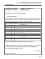
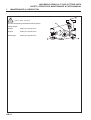
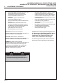
2.2 PRODUCT IDENTIFICATION
A
B
C
D
E
GB-2
Machine Name
Serial Number
Year of Manufacture
Machine Weight
Engine Power
JACOBSEN FAIRWAY & T-PLEX CUTTING UNITS
SAFETY, OPERATORS, MAINTENANCE & PARTS MANUAL
2
INTRODUCTION
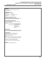
2.3
•
GUIDELINES FOR THE DISPOSAL
OF SCRAP PRODUCTS
When it has been identified that a turf care
product has no further functional value and
requires disposal, the following actions should
be taken.
These guidelines should be used in
conjunction with applicable Health, Safety and
Environmental legislation and use of approved
local facilities for waste disposal and recycling.
• Position the machine in a suitable
location for any necessary lifting
equipment to be used.
• Use appropriate tools and Personal
Protective Equipment (PPE) and take
guidance from the technical manuals
applicable to the machine.
• Remove and store appropriately:
1. Batteries
2. Fuel residue
3. Engine coolant
4. Oils
• Disassemble the structure of the
machine referring to the technical
manuals where appropriate. Special
attention should be made for dealing
with ‘stored energy’ within
pressurised elements of the machine
or tensioned springs.
• Any items that still have a useful
service life as second hand
components or can be re-serviced
should be separated and returned to
the relevant centre.
•
•
•
Plastics
• Identifiable
• Recyclable
• Non recyclable
• Not identified
• Rubber
Items that cannot be separated
economically into different material
groups should be added to the
‘General waste’ area.
Do not incinerate waste.
Finally update machinery records to indicate
that the machine has been taken out of service
and scrapped.
Other worn out items should be
separated into material groups for
recycling and disposal consistent with
available facilities. More common
separation types are as follows:
• Steel
• Non ferrous metals
• Aluminium
• Brass
• Copper
GB-3
3
JACOBSEN FAIRWAY & T-PLEX CUTTING UNITS
SAFETY, OPERATORS, MAINTENANCE & PARTS MANUAL
SAFETY INSTRUCTIONS
This safety symbol indicates important safety
messages in this manual. When you see this
symbol, be alert to the possibility of injury,
carefully read the message that follows, and
inform other operators.
•
3.1OPERATING INSTRUCTIONS
• Ensure that the instructions in this book are read
and fully understood.
• No person should be allowed to operate this
machine unless they are fully acquainted with all
the controls and the safety procedures.
• Never allow children or people unfamiliar with
these instructions to use this machine. Local
regulations may restrict the age of the operator.
•
3.2SAFETY SIGNS
• It is essential all safety labels are kept legible, if
they are missing or illegible they must be
replaced. If any part of the machine is replaced
and it originally carried a safety label, a new label
must be affixed to the replacement part. New
safety labels are obtainable from Ransomes
dealers.
3.3STARTING THE ENGINE
• Before starting the engine check that the brakes
are applied, drives are in neutral, guards are in
position and intact, and bystanders are clear of
the machine.
• Do not run the engine in a building without
adequate ventilation.
3.4DRIVING THE MACHINE
• Before moving the machine, check to ensure that
all parts are in good working order, paying
particular attention to brakes, tyres, steering and
the security of cutting blades.
• Replace faulty silencers, mow only in daylight or
good artificial light
• Always observe the Highway Code both on and
off the roads. Keep alert and aware at all times.
Watch out for traffic when crossing or near
roadways.
• Stop the blades rotating before crossing surfaces
other than grass.
GB-4
•
•
•
•
•
•
•
Remember that some people are deaf or blind
and that children and animals can be
unpredictable.
Keep travelling speeds low enough for an
emergency stop to be effective and safe at all
times, in any conditions.
Remove or avoid obstructions in the area to be
cut, thus reducing the possibility of injury to
yourself and/or bystanders.
When reversing, take special care to ensure
that the area behind is clear of obstructions
and/or bystanders. DO NOT carry passengers.
Keep in mind that the operator or user is
responsible for accidents or hazards occurring
to other people or their property.
When the machine is to be parked, stored or
left unattended, lower the cutting means unless
the transport locks are being used.
While mowing, always wear substantial
footwear and long trousers. Do not operate the
equipment when barefoot or wearing open
sandals.
Check the grass catcher frequently for wear or
deterioration. After striking a foreign object
Inspect the lawnmower for damage and make
repairs before restarting and operating the
equipment.
If the machine starts to vibrate abnormally,
check immediately.
3.5
TRANSPORTING
• Ensure that the cutting units are securely
fastened in the transport position. Do not
transport with cutting mechanism rotating.
• Drive the machine with due consideration of
road and surface conditions, inclines and local
undulations.
• Sudden decelerating or braking can cause the
rear wheels to lift.
• Remember that the stability of the rear of the
machine is reduced as the fuel is used.
JACOBSEN FAIRWAY & T-PLEX CUTTING UNITS
SAFETY, OPERATORS, MAINTENANCE & PARTS MANUAL
3
SAFETY INSTRUCTIONS
3.6 LEAVING THE DRIVING POSITION
• Park the machine on level ground.
• Before leaving the driving position, stop the
engine and make sure all moving parts are
stationary. Apply brakes and disengage all
drives. Remove the starter key.
3.7 SLOPES
TAKE EXTRA CARE WHEN WORKING ON
SLOPES
• Local undulations and sinkage will change the
general slope. Avoid ground conditions which can
cause the machine to slide.
• Keep machine speeds low on slopes and during
tight turns.
• Sudden decelerating or braking can cause the
rear wheels to lift. Remember there is no such
thing as a “safe” slope.
• Travel on grass slopes requires particular care.
DO NOT USE ON SLOPES GREATER THAN 15°
IMPORTANT: When working on any slope select
weight transfer, having adjusted to provide
adequote traction.
3.8 BLOCKED CUTTING CYLINDERS
• Stop the engine and make sure all moving parts
are stationary.
• Apply brakes and disengage all drives.
• Release blockages with care. Keep all parts of
the body away from the cutting edge. Beware of
energy in the drive which can cause rotation
when the blockage is released.
• Keep other people away from the cutting units as
rotation of one cylinder can cause the others to
rotate.
3.9 ADJUSTMENTS, LUBRICATION AND
MAINTENANCE
• Stop the engine and make sure all moving parts
are stationary.
• Apply brakes and disengage all drives.
• Read all the appropriate servicing instructions.
• Use only the replacement parts supplied by the
original manufacturer.
• When adjusting the cutting cylinders take care
not to get hands and feet trapped when rotating
cylinders.
• Make sure that other people are not touching any
cutting units, as rotation of one cylinder can
cause the others to rotate.
• To reduce the fire hazard, keep the engine,
•
•
•
•
•
•
•
•
•
•
•
•
•
•
•
•
•
silencer and battery compartments free of grass,
leaves or excessive grease.
Replace worn or damaged parts for safety.
When working underneath lifted parts or
machines, make sure adequate support Is
provided.
Do not dismantle the machine without releasing
or restraining forces which can cause parts to
move suddenly.
Do not alter engine speed above maximum
quoted in Engine Specification. Do not change
the engine governor settings or overspeed the
engine. Operating the engine at excessive speed
may increase the hazard of personal injury.
When refuelling, STOP THE ENGINE, DO NOT
SMOKE. Add fuel before starting the engine,
never add fuel while the engine is running.
Use a funnel when pouring fuel from a can into
the tank.
Do not fill the fuel tank beyond the bottom of the
filler neck.
Replace all fuel tank and container caps
securely.
Store fuel in containers specifically designed for
this purpose.
Refuel outdoors only and do not smoke while
refuelling.
If fuel is spilled, do not attempt to start the
engine but move the machine away from the area
of spillage and avoid creating any source of
ignition until fuel vapours have dissipated.
Allow the engine to cool before storing in any
enclosure.
Never store the equipment with fuel in the tank
inside a building where fumes may reach an open
flame or spark.
If the fuel tank has to be drained, this should be
done outdoors.
Do not spill fuel onto hot components.
When servicing batteries, DO NOT SMOKE, and
keep naked lights away.
Do not place any metal objects across the
terminals.
GB-5
JACOBSEN FAIRWAY & T-PLEX CUTTING UNITS
SAFETY, OPERATORS, MAINTENANCE & PARTS MANUAL
3
SAFETY INSTRUCTIONS
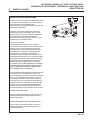
DANGER - Indicates an imminently hazardous
situation which, if not avoided, WILL result in death
or serious injury.
IMPORTANT: Transport speed is for highway use
only. Never select transport speed on grass areas
or uneven or unsurfaced roads or tracks.
WARNING - Indicates a potentially hazardous
situation which, if not avoided, COULD result in
death or serious injury.
The operating Instructions for the Cutting Units are
contained in a separate Publication .
CAUTION - Indicates a potentially hazardous
situation which, if not avoided, MAY result in minor
or moderate injury and property damage. It may
also be used to alert against unsafe practices.
WARNING
Hydraulic Fluid escaping under pressure can
penetrate skin and do serious damage.
Immediate medical assistance must be
sought.
GB-6
JACOBSEN FAIRWAY & T-PLEX CUTTING UNITS
SAFETY, OPERATORS, MAINTENANCE & PARTS MANUAL
4
SPECIFICATION
CONSTRUCTION
Heavy duty welded pressed steel construction
CYLINDER:
Diameter:
Width of cut:
Number of knives:
Height of cut:
165mm (6-1/2in)
660mm (26in)
7 and 11
12mm - 47mm
(15/32in - 1-25/64in)
CUTTING CYLINDER TO BOTTOM BLOCK
ADJUSTMENT
Self locking notched hand micro adjusters. Each
notch giving 0.04mm (0.0015in) of movement.
HEIGHT OF CUT ADJUSTMENT
Front roll:
Threaded roll carriage &
locknuts.
Rear roll:
Coarse adjustment:Three
position housing mounting.
Fine adjustment: Threaded roll carriage & locknuts
REAR ROLL
Full width 75mm (3in) diameter plain roll running on
taper roller bearings with shaft seals and lubricators.
FRONT ROLL
Full width 75mm (3in) diameter grooved roll running
on taper roller bearings with shaft seals and
lubricators.
or
Full width 75mm (3in) diameter plain roll running on
taper roller bearings with shaft seals and lubricators.
BOTTOM BLOCK & BLADE
Blade replaceable, mounted onto welded steel
constructed bottom block.
TRANSMISSION
By hydraulic motor through cardan shaft to cutting
cylinder.
GB-7
JACOBSEN FAIRWAY & T-PLEX CUTTING UNITS
SAFETY, OPERATORS, MAINTENANCE & PARTS MANUAL
4
SPECIFICATION
EC Declaration of Incorporation
EG Verklaring van Conformiteit
Dichiarazione di costituzione CE
Överensstämmelse med EU:s regler
Declaración de Incorporación de la CE
Déclaration de constitution CE
EG Einbauerklärung
EF Erklæring om overholdelse af standard
EY-liitäntädeklaraatio
We the undersigned Nous, soussignés Wij, de ondergetekenden
Wir, die Unterzeichneten Noi sottoscritti Undertegnede Nedanstående företag
Me allekirjoittaneet Nosotros, los abajo firmantes:
Ransomes Jacobsen Limited
Central Avenue, Ransomes Europark, Ipswich, England, IP3 9QG
Certify that the cutting unit Certifions que le bloc de coupe Verklaren hierbij dat de maai-eenheid Bescheinigen,
daß die Schneidanlage Certifichiamo che il gruppo di taglio Attesterer herved at dette klippeaggregat, Intygar att
klippenheten Vakuutamme, että leikkuulaite Certificamos que la unidad cortadora
Make Marque Merk Fabrikat Marca Fabrikat Märke Merkki Marca: Ransomes
Product C ode
Series D escription
FAIR WAY 250
JMAB401
AAG
7 Kni fe, Floati ng Head C utti ng Uni t
JMAB402
AAH
11 Kni fe, Floati ng Head C utti ng Uni t
FAIR WAY 305 & 405
JMAB347
AAJ
7 Kni fe, Floati ng Head C utti ng Uni t
JMAB348
AAK
11 Kni fe, Floati ng Head C utti ng Uni t
Conforms to the Harmonised standard Est conforme à la norme Voldoet aan de Standaard
Mit der Norm E conforme allo standard Overholder den standard överstämmer med den standarden
Noudattaa standardia Conforma con la norma:
EN836
This cutting unit has been designed to be fitted to the Ce bloc de coupe a été conçu pour se monter sur Deze maaieenheid werd ontworpen om te worden gemonteerd op de übereinstimmt. Diese Schneidanlage wurde zur
Installation in Questo gruppo di taglio è stata progettato per essere installato su Dette klippeaggregat er beregnet til
montering på Denna klippenhet är avsett att monteras på Tämä leikkuulaite on suunniteltu sopimaan seuraavaan
Esta unidad cortadora ha sido diseñada para su montaje en:
Fairway 250 series DH & ZL / Fairway 305 series CG & ZR / Fairway 405 series CH & ZS
T. Lansdell
Technical Director
Certificate Number:Jacobsen Fairway Incorp (rev.2)
GB-8
JACOBSEN FAIRWAY & T-PLEX CUTTING UNITS
SAFETY, OPERATORS, MAINTENANCE & PARTS MANUAL
4
SPECIFICATION
EC Declaration of Incorporation
EG Verklaring van Conformiteit
Dichiarazione di costituzione CE
Överensstämmelse med EU:s regler
Declaración de Incorporación de la CE
Déclaration de constitution CE
EG Einbauerklärung
EF Erklæring om overholdelse af standard
EY-liitäntädeklaraatio
We the undersigned Nous, soussignés Wij, de ondergetekenden
Wir, die Unterzeichneten Noi sottoscritti Undertegnede Nedanstående företag
Me allekirjoittaneet Nosotros, los abajo firmantes:
Ransomes Jacobsen Limited
Central Avenue, Ransomes Europark, Ipswich, England, IP3 9QG
Certify that the cutting unit Certifions que le bloc de coupe Verklaren hierbij dat de maai-eenheid Bescheinigen,
daß die Schneidanlage Certifichiamo che il gruppo di taglio Attesterer herved at dette klippeaggregat, Intygar att
klippenheten Vakuutamme, että leikkuulaite Certificamos que la unidad cortadora
Make Marque Merk Fabrikat Marca Fabrikat Märke Merkki Marca: Ransomes
P roduct C ode
S eries D escription
T-P LE X 185 series ZX
JMA B 339
26" 5 K nife, Fixed Head C utting Unit
JMA B 431
26" 5 K nife, Floating Head C utting Unit
JMA B 429
26" 7 K nife, Floating Head C utting Unit
JMA B 430
26" 11 K nife, Floating Head C utting Unit
T-P LE X 185 series ZY
JMA B 306
30" 5 K nife, FIX E D Head C utting Unit
JMA B 308
30" 7 K nife, Floating Head C utting Unit
JMA B 310
30" 11 K nife, Floating Head C utting Unit
T-P LE X 185 series D E
LMA C 015
22" 7 K nife, Floating Head C utting Unit RHD
JMA B 429
26" 7 K nife, Floating Head C utting Unit RHD
LMA C 016
22" 7 K nife, Floating Head C utting Unit LHD
Conforms to the Harmonised standard Est conforme à la norme Voldoet aan de Standaard
Mit der Norm E conforme allo standard Overholder den standard överstämmer med den standarden
Noudattaa standardia Conforma con la norma:
EN836
This cutting unit has been designed to be fitted to the Ce bloc de coupe a été conçu pour se monter sur Deze maaieenheid werd ontworpen om te worden gemonteerd op de übereinstimmt. Diese Schneidanlage wurde zur
Installation in Questo gruppo di taglio è stata progettato per essere installato su Dette klippeaggregat er beregnet til
montering på Denna klippenhet är avsett att monteras på Tämä leikkuulaite on suunniteltu sopimaan seuraavaan
Esta unidad cortadora ha sido diseñada para su montaje en:
T-Plex 185 series ZX, ZY & DE
Certificate Number:4121661 (rev.2)
T. Lansdell
Technical Director
GB-9
JACOBSEN FAIRWAY & T-PLEX CUTTING UNITS
SAFETY, OPERATORS, MAINTENANCE & PARTS MANUAL
4
SPECIFICATION
EC Declaration of Incorporation
•
EG Verklaring van Conformiteit
•
Dichiarazione di costituzione CE
•
Överensstämmelse med EU:s regler •
Declaración de Incorporación de la CE
Déclaration de constitution CE
EG Einbauerklärung
EF Erklæring om overholdelse af standard
EY-liitäntädeklaraatio
We the undersigned • Nous, soussignés • Wij, de ondergetekenden •
Wir, die Unterzeichneten • Noi sottoscritti • Undertegnede • Nedanstående företag •
Me allekirjoittaneet • Nosotros, los abajo firmantes:
Ransomes Jacobsen Limited
West Road, Ransomes Europark, Ipswich, England, IP3 9TT
Certify that the cutting unit • Certifions que le bloc de coupe • Verklaren hierbij dat de maai-eenheid • Bescheinigen,
daß die Schneidanlage • Certifichiamo che il gruppo di taglio • Attesterer herved at dette klippeaggregat, • Intygar att
klippenheten • Vakuutamme, että leikkuulaite • Certificamos que la unidad cortadora
Make • Marque • Merk • Fabrikat • Marca • Fabrikat • Märke • Merkki • Marca: Jacobsen
Product C ode
Series D escription
TR 3 series FG
LMAC 196
FC
7 Kni fe, Floati ng Head C utti ng Uni t
LMAC 194
FD
5 Kni fe, Fi xed Head C utti ng Uni t
LMAC 195
FE
5 Kni fe, Floati ng Head C utti ng Uni t
LMAC 197
FF
11 Kni fe, Floati ng Head C utti ng Uni t
TR 3 series EJ
47116
7 Kni fe, Fi xed Head Rear C utti ng Uni t Ri ght Hand D ri ve
47115
7 Kni fe, Fi xed Head Front C utti ng Uni t Left Hand D ri ve
47114
7 Kni fe, Fi xed Head Front C utti ng Uni t Ri ght Hand D ri ve
Conforms to the Harmonised standard • Est conforme à la norme • Voldoet aan de Standaard •
Mit der Norm • E’ conforme allo standard • Overholder den standard • överstämmer med den standarden •
Noudattaa standardia • Conforma con la norma:
EN836
This cutting unit has been designed to be fitted to the • Ce bloc de coupe a été conçu pour se monter sur • Deze maaieenheid werd ontworpen om te worden gemonteerd op de • übereinstimmt. Diese Schneidanlage wurde zur
Installation in • Questo gruppo di taglio è stata progettato per essere installato su • Dette klippeaggregat er beregnet til
montering på • Denna klippenhet är avsett att monteras på • Tämä leikkuulaite on suunniteltu sopimaan seuraavaan •
Esta unidad cortadora ha sido diseñada para su montaje en:
Jacobsen TR3 series EJ & FG
T. Lansdell
Technical Director
Certificate Number:Jacobsen TR3 Incorp (rev.0)
GB-10
4
SPECIFICATION
JACOBSEN FAIRWAY & T-PLEX CUTTING UNITS
SAFETY, OPERATORS, MAINTENANCE & PARTS MANUAL
GB-11
JACOBSEN FAIRWAY & T-PLEX CUTTING UNITS
SAFETY, OPERATORS, MAINTENANCE & PARTS MANUAL
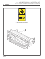
5
DECALS
A = 009034940Cation rotating blades
GB-12
JACOBSEN FAIRWAY & T-PLEX CUTTING UNITS
SAFETY, OPERATORS, MAINTENANCE & PARTS MANUAL
6
ASSEMBLY & OPERATION
FITTING THE UNIT TO THE MACHINE
Read the Safety Instructions
Fitting the unit to the machine is described in the
power unit operating instruction book.
OPERATING THE UNIT
Read the Safety Instructions
Operating the unit is described in the power unit
operating instruction book.
GB-13
7
JACOBSEN FAIRWAY & T-PLEX CUTTING UNITS
SAFETY, OPERATORS, MAINTENANCE & PARTS MANUAL
MAINTENANCE & LUBRICATION
Read the Safety Instructions
Lubricate the following with Shell Darina R2 grease.
Cutting cylinder
bearings
weekly or every 25 hours.
Unit pivot
weekly or every 25 hours.
Roll bearings
weekly or every 25 hours.
GB-14
JACOBSEN FAIRWAY & T-PLEX CUTTING UNITS
SAFETY, OPERATORS, MAINTENANCE & PARTS MANUAL
7
MAINTENANCE & LUBRICATION
Read the Safety Instructions
Check all nuts and bolts every 75 hours
Lubrication of Direct Drive Hydraulic Motor
(Every 400 hours)
Lower all cutting units onto level ground. Before
leaving the driving position, stop the engine and
make sure all moving parts are stationary. Apply
brakes and disengage all drives. remove the starter
key. The direct drive hydraulic motor can be removed
from the cutting unit by removing the two screws and
washers holding the motor to the bearing housing.
Carefully withdraw the motor from the bearing
housing, it is important not to contaminate the motor
shaft or internal splines of the cutting cylinder. If for
any reason they are contaminated, they should be
cleaned by degreasing. Liberally lubricate the motor
and cylinder splines with Shell Malleus JB1 grease
(Textron Part no. MBE3927) before reassembling.
GB-15
JACOBSEN FAIRWAY & T-PLEX CUTTING UNITS
SAFETY, OPERATORS, MAINTENANCE & PARTS MANUAL
8
ADJUSTMENT
Read Safety Instructions
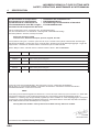
HEIGHT OF CUT
It is important to set the rear roll parallel to the
bottom blade (bedknife) in order to achieve the
minimum height of cut setting for the three ranges of
height, in the three sets of mounting housing (D) bolt
holes. Positions 'A','B' &'C'.
Setting the minimum height with the mounting
housings (D) in position 'A' will allow minimum height
and parallelism to be achieved in each of the other
two positions 'B' & 'C'.
Once the range has been chosen the actual height
of cut is set by adjusting the front roll only by
carriage screws (F) and locknuts (J).
TO SET REAR ROLL
with a new bottom blade (bedknife)
1.
Set the height of cut setting bar (G)as follows:
a. Screw X to 12mm(15/32in) under the head.
b. Screw Y to 6.5mm (1/4in) to screw thread
tip.
Note: The difference between screw X and screw Y
is 5.5mm (7/32in).
2.
Set roll carriage mounting housing(D) bolts
into holes 'A'.
3.
Place the setting bar (G)as shown at one end
of the bottom blade with the screw head X
over the lip and screw thread Y tip against
base of blade.
4.
Adjust the roll to the setting bar (G) with the
two locknuts(H) holding setting bar screws
in contact.
5.
Repeat for other end of bottom blade
(bedknife).
TO SET HEIGHT OF CUT
Chose the range of height in which cutting is to be
carried out and then adjust front roll only.
1.
Preset the height of cut setting bar (G)as
follows:
a. Screw X to the required height of cut under
the head.
b. Screw Y is not used.
2.
At one end of the bottom blade (bedknife) lay
setting bar (G) on rear roll with screw head
over bottom blade (bedknife) lip.
3.
Adjust front roll to the setting bar by means of
the two front locknuts (J).
4.
Repeat for the other end of the bottom blade
(bedknife).
GB-16
Height of Cut
R an g e
Minimum
Height of Cut
Maximum
Height of Cut
Holes 'A'
12.0mm
15/32"
19.0mm
3/4"
Holes 'B'
19.0mm
3/4"
35.0mm
1-3/8"
Holes 'C'
27.0mm
1-1/16"
47.0mm
1-25/64"
CAUTION
The height of cut range for each set of
holes takes into account the requirement
of the cutting unit to float. Increasing the
maximum height of cut in any of the hole
setting ranges could restrict the ability of
the cutting unit to float.
JACOBSEN FAIRWAY & T-PLEX CUTTING UNITS
SAFETY, OPERATORS, MAINTENANCE & PARTS MANUAL
8
ADJUSTMENT
CUTTING CYLINDER TO BOTTOM BLADE
ADJUSTMENT
To check that the cutting cylinder is set to the
bottom blade correctly, hold a piece of thin paper
between the edge of the blade and the spiral cutters
and turn the cylinder manually.
The paper should be cut cleanly along the total
length of the bottom blade, if not, some adjustment
may be necessary, BUT DO NOT OVERTIGHTEN.
Alternatively if the cylinder is worn it may require
back lapping before adjusting.
To adjust:
1. To adjust the cylinder to the bottom blade lift and
turn alternately left and right hand handwheels (A
Fig.3). (clockwise to put on cut anticlockwise to
take off cut) and release, keep turning the
handwheel until it locates in the serrated locking
ring. The adjuster is of the notched type and each
notch is moving the cylinder in increments of
approximately 0.04mm (0.0015in).
THIS IS A SELF LOCKING MECHANISM THERE
BEING NO NECESSITY TO UNLOCK OR LOCK
THE MECHANISM.
IMPORTANT: IN ROUGH GROUND CONDITIONS
IT MAY BE NECESSARY TO LOCK THE NUTS
SECURING THE BEARING HOUSINGS TO THE
SIDE FRAME WHERE THEY RUN IN ADJUSTING
SLOTS TO RETAIN CYLINDER TO BOTTOM
BLADE SETTINGS. EXPERIENCE WILL DICTATE
THIS. THE NUTS SHOULD NORMALLY BE
TIGHTENED FULLY AND THEN BACKED OFF 1/2
A TURN TO ALLOW HANDWHEEL ADJUSTMENT
WITHOUT THE NEED TO UNLOCK THE NUTS
FIRST.
CUTTING CYLINDER BEARINGS
The cutting cylinder bearings are self adjusting taper
roller bearings and require no adjustments.
FRONT AND REAR ROLL BEARINGS
The roll bearings are self adjusting taper roller
bearings and require no adjustment
GB-17
JACOBSEN FAIRWAY & T-PLEX CUTTING UNITS
SAFETY, OPERATORS, MAINTENANCE & PARTS MANUAL
9
END OF SEASON
a. The units should be thoroughly cleaned down to
remove all accumulations of grass clippings and
debris.
b. Turn the cutting cylinders to clean the cutting
edges.
c. Apply a little oil with a brush to the spiral cutters
to prevent rusting.
d. Slowly turn the cylinders which will then spread
the oil on the bottom blades.
WARNING NOTE: Do not turn the cylinders
manually.
GB-18
JACOBSEN FAIRWAY & T-PLEX CUTTING UNITS
SAFETY, OPERATORS, MAINTENANCE & PARTS MANUAL
10
GUARANTEE
GUARANTEE
We GUARANTEE that should any defect in workmanship or material occur in the
goods within TWO YEARS or two thousand hours (on models equipped with hour
meters), or whichever occurs first.
Exception to this warranty will be Aeration products, which are covered for a period
of TWO-YEARS or five hundred hours (on models equipped with hour meters) or
whichever occurs first.
We will repair, or at our option, replace the defective part without making any charge
for labour or for materials, provided that the claim under this guarantee is made
through an authorised dealer and that the defective part shall, if we so request, be
returned to us or to the dealer.
This guarantee is in addition to, and does not exclude, any condition or warranty
implied by law, except that we accept no liability in respect of used/second-hand
goods, or in respect of defects which in our opinion are in any way or to any extent
attributable to misuse, lack of reasonable care or ordinary wear and tear, or to the
fitting of spares, replacements, or extra components which are not supplied or
approved by us for the purpose. The use of non-recommended oil or lubricant
nullifies the guarantee.
Damage through transport or normal wear does not come under the guarantee.
The warranty is extended to the original purchaser only and is not transferable to
subsequent owners. The warranty period begins on the date the product is delivered
to the end user (customer), unless otherwise agreed with the manufacturer. At the
end of the first year the owner must have the product serviced by an authorised
dealer to be eligible for the second year of warranty coverage.
SALES & SERVICE
A network of authorised Sales and Service dealers has been established and these
details are available from your supplier.
When service attention, or spares, are required for the machine, within or after the
guarantee period your supplier or any authorised dealer should be contacted.
Always quote the registered number of the machine.
If any damage is apparent when delivery is made, report the details at once to the
supplier of the machine.
GB-19
JACOBSEN FAIRWAY & T-PLEX CUTTING UNITS
SAFETY, OPERATORS, MAINTENANCE & PARTS MANUAL
GB-20
1
INHALT
Contents:
JACOBSEN FAIRWAY & T-PLEX CUTTING UNITS
HANDBUCH ZU SICHERHEIT, BEDIENUNG, WARTUNG UND
ERSATZTEILEN
Page
2
2.2
2.1
2.3
IEINLEITUNG .................................................................................................. 2
PRODUKTIDENTIFIKATION ............................................................................ 2
WICHTIG ......................................................................................................... 2
GUIDELINES FOR THE DISPOSALOF SCRAP PRODUCTS .......................... 2
3
3.1
3.2
3.3
3.4
3.5
3.6
3.7
3.8
3.9
ALLGEMEINE SICHERHEIT ........................................................................... 4
BEDIENUNGSANLEITUNGEN ........................................................................ 4
SICHERHEITSAUFKLEBER ........................................................................... 4
ANLASSEN DES MOTORS ............................................................................ 4
FAHREN DER MASCHINE ALLGEMEINE SICHERHEIT ................................. 5
TRANSPORT .................................................................................................. 5
VERLASSEN DES FAHRERSITZES ............................................................... 5
GEFÄLLE ....................................................................................................... 5
BLOCKIERTE SCHNEIDZYLINDER ................................................................ 5
EINSTELLUNGEN, SCHMIERUNG UND WARTUNG ...................................... 5
4
TECHNISCHE DATEN ..................................................................................... 7
5
AUFKLEBER ................................................................................................. 10
6
MONTAGE DER EINHEIT AN DIE MASCHINE ............................................... 11
7
SCHMIERUNG ............................................................................................... 12
8
EINSTELLUNGEN .......................................................................................... 14
9
WARTUNG AM ENDE DER MÄHSAISON ..................................................... 16
10
GARANTIE ..................................................................................................... 17
DE-1
2
IEINLEITUNG
2.1
JACOBSEN FAIRWAY & T-PLEX CUTTING UNITS
HANDBUCH ZU SICHERHEIT, BEDIENUNG, WARTUNG UND
ERSATZTEILEN
WICHTIG
WICHTIG: Diese Maschine ist eine Präzisionsmaschine und ihre Leistung hängt davon ab, wie sie betrieben
und instandgehalten wird.
Diese Betriebsanleitung sollte als Teil der Maschine angesehen werden. Wir empfehlen Lieferanten sowohl
von neuen als auch von gebrauchten Maschinen, einen Nachweis darüber zu behalten, daß dieses
Handbuch mit der Maschine geliefert wurde.
Diese Maschine muß ausschließlich zum traditionellen Schneiden von Gras verwendet werden. Wenn es für
irgendeinen anderen Zweck verwendet wird, wird das als dem geplanten Gebrauch widersprechend
angesehen. Ein Einhalten und strengstes Befolgen der vom Hersteller angegebenen Bedingungen bezüglich
Betrieb, Instandhaltung und Reparatur stellen ebenfalls ein außerordentlich wichtiges Element des
beabsichtigten Gebrauchs dar.
Bevor man versucht, diese Maschine zu betätigen, MÜSSEN ALLE Personen, die sie bedienen, dieses
Handbuch durchlesen und sich selbst ausführlich mit der Sicherheitsanweisung, Regelung, Schmierung und
Wartung vertraut machen.
Bestimmungen zur Unfallverhütung, alle anderen allgemein anerkannten Bestimmungen bezüglich Sicherheit
und Berufsmedizin sowie alle Straßenverkehrsordnungen sollten jederzeit befolgt werden.
Wenn willkürliche Modifizierungen an dieser Maschine ausgeführt werden, kann der Hersteller evtl. von
seiner Verantwortung für jegliche daraus entstandenen Schäden oder Verletzungen befreit werden.
2.2 PRODUKTIDENTIFIKATION
A
B
C
D
E
DE-2
Maschinenbezeichnung
Seriennummer
Herstellungsjahr
Gewicht der Maschine
Motorleistung
2
EINLEITUNG
2.3
JACOBSEN FAIRWAY & T-PLEX CUTTING UNITS
HANDBUCH ZU SICHERHEIT, BEDIENUNG, WARTUNG UND
ERSATZTEILEN
HINWEISE ZUR ENTSORGUNG VON
ALTPRODUKTEN
•
Wenn entschieden worden ist, dass ein
Rasenpflegeprodukt keinen weiteren
funktionalen Wert hat und entsorgt werden
muss, ist wie folgt vorzugehen.
Diese Hinweise sind zusammen mit der
entsprechenden Gesetzgebung zu Arbeits- und
Umweltschutz zu befolgen, und für Entsorgung
und Recycling sind zugelassene örtliche
Einrichtungen zu verwenden.
•
•
•
Die Maschine so aufstellen, dass im
Bedarfsfall die erforderlichen
Hebevorrichtungen verwendet werden
können.
Andere abgenutzte Teile sind nach
Materialgruppen für Recycling und
Entsorgung entsprechend den
verfügbaren Einrichtungen zu
sortieren. Die Materialien werden im
allgemeinen wie folgt getrennt:
•
Stahl
•
Nichteisenmetalle
•
Geeignete Werkzeuge und
persönliche Schutzausrüstung (PSA)
verwenden, und die technischen
Handbücher für die Maschine zu Rate
ziehen.
2. Kraftstoffreste
•
Die Maschine demontieren; dabei die
technischen Handbücher soweit
erforderlich zu Rate ziehen.
‚Gespeicherter Energie‘ in
Druckelementen der Maschine oder in
gespannten Federn ist besondere
Aufmerksamkeit zu schenken.
•
Alle Bauteile, die als Gebrauchtteile
noch weiter verwendet oder die
repariert werden können, sind
auszusortieren und an das relevante
Zentrum zurückzugeben.
•
Messing
•
Kupfer
Kunststoffe
•
•
Identifizierbar
•
recyclingfähig
•
nicht
recyclingfähig
Nicht identifizierbar
Gummi
•
Teile, die nicht auf wirtschaftliche
Weise in die verschiedenen
Materialgruppen aussortiert werden
können, sind dem ‚allgemeinen Abfall‘
hinzuzufügen.
•
Abfall nicht verbrennen.
3. Motorkühlmittel
4. Öle
Aluminium
•
Folgendes ist auf geeignete Weise aus
der Maschine zu entfernen und zu
lagern:
1. Batterien
•
Zuletzt ist das Maschinenregister zu
aktualisieren und aufzuzeichnen, dass die
Maschine außer Betrieb genommen und
verschrottet worden ist.
DE-3
3
JACOBSEN FAIRWAY & T-PLEX CUTTING UNITS
HANDBUCH ZU SICHERHEIT, BEDIENUNG, WARTUNG UND
ERSATZTEILEN
ALLGEMEINE SICHERHEIT
3.4
•
Dieses Sicherheitssymbol zeigt wichtige
Sicherheitshinweise in diesem Handbuch an. Wenn
Sie dieses Symbol sehen, sollten Sie sich der
Möglichkeit einer Verletzung bewußt sein, den
darauffolgenden Hinweis genau durchlesen und
andere Personen, die diese Maschine bedienen,
darüber informieren.
3.1
•
•
•
3.2
•
3.3
•
•
BEDIENUNGSANLEITUNGEN
Lesen und verstehen Sie alle Anweisungen in
diesem Handbuch.
Diese Maschine darf nur von Personen
bedient werden, die mit allen
Bedienelementen und den
Sicherheitsbestimmungen völlig vertraut sind.
Die Maschine niemals durch Kinder oder mit
der Bedienung nicht vertraute Personen
bedienen lassen. In verschiedenen Ländern ist
für die Bedienung dieser Maschine ein
Mindestalter vorgeschrieben.
SICHERHEITSAUFKLEBER
Alle Sicherheitsaufkleber müssen lesbar sein,
fehlende und unleserlich gewordene sind
unverzüglich zu ersetzen. Falls ein Teil der
Maschine ausgetauscht wird, und das
Originalteil einen Sicherheitsaufkleber trug, so
muß auf dem Ersatzteil ebenfalls ein
Sicherheitsaufkleber angebracht werden.
Neue Sicherheitsaufkleber sind bei Ihrem
Ransomes-Händler erhältlich.
ANLASSEN DES MOTORS
Vergewissern Sie sich vor dem Anlassen des
Motors, daß die Bremsen angezogen sind,
die Antriebe auf Leerlauf geschaltet sind, die
Schutzvorrichtungen richtig angebracht und
intakt sind und sich keine Personen in der
Nähe der Maschine aufhalten.
Motor niemals in geschlossenen Räumen
ohne ausreichende Belüftung laufen lassen.
•
•
•
•
•
•
•
•
•
•
•
•
DE-4
FAHREN DER MASCHINE
Vergewissern Sie sich vor dem Fahren der
Maschine, daß sich alle Teile in
einwandfreiem Zustand befinden. Besonders
sorgfältig müssen Bremsen, Reifen, Lenkung
und die Messer der Schneidzylinder überprüft
werden.
Ersetzen Sie defekte Schalldämpfer, mähen
Sie nur bei Tageslicht oder ausreichender
künstlicher Beleuchtung.
Beachten Sie die Straßenverkehrsordnung
auch abseits der Straße. Seien Sie jederzeit
wachsam und konzentriert. Achten Sie auf
den Verkehr, wenn Sie Straßen kreuzen oder
neben ihnen fahren.
Schalten Sie die Schneidzylinder aus, wenn
Sie Flächen ohne Grasbewuchs passieren.
Denken Sie daran, daß manche Leute taub
oder blind sind und daß Kinder und Tiere
unberechenbar sind.
Wählen Sie Ihre Fahrgeschwindigkeit so, daß
Sie jederzeit und unter allen Bedingungen
eine sichere Notbremsung vornehmen
können.
Entfernen Sie alle Fremdkörper von der
Arbeitsfläche und umfahren Sie Hindernisse.
Dadurch verringert sich die Verletzungsgefahr
für den Bediener und Nebenstehende.
Vergewissern Sie sich vor dem
Rückwärtsfahren, daß sich hinter der
Maschine keine Hindernisse befinden und
sich dort niemand aufhält. NEHMEN SIE
KEINE BEIFAHRER MIT.
Denken Sie daran, daß der Bediener für
Unfälle mit Personen oder Beschädigungen
der Arbeitsfläche verantwortlich ist.
Beim unbeaufsichtigten Abstellen der
Maschine senken Sie die Schneideinheiten
ab oder benutzen die Transportsicherungen.
Tragen Sie während des Mähens immer
festes Schuhwerk und lange Hosen.
Benutzen Sie die Maschine nicht barfuß oder
mit offenen Sandalen.
Prüfen Sie regelmäßig die Grasfangkörbe auf
Verschleiß oder Zustandsänderung. Nach
einer Kollosion mit Fremdkörpern überprüfen
Sie die Maschine auf Beschädigungen und
führen die notwendigen Reparaturen vor der
weiteren Benutzung durch.
Bei auftretenden außergewöhnlichen
Vibrationen unverzüglich die Ursache
feststellen und beseitigen.
JACOBSEN FAIRWAY & T-PLEX CUTTING UNITS
HANDBUCH ZU SICHERHEIT, BEDIENUNG, WARTUNG UND
ERSATZTEILEN
ALLGEMEINE SICHERHEIT
3
3.5
•
•
•
•
3.6
•
•
TRANSPORT
Schneideinheiten in Transportstellung mit den
Transportsicherungen sichern.
Die Maschine niemals mit drehenden
Schneidzylindern transportieren.
Berücksichtigen Sie beim Fahren die
Straßen- und Bodenbeschaffenheit,
Steigerungen und einzelne Unebenheiten.
Durch plötzliche Geschwindigkeitsverringerung oder Bremsen kann das
Hinterrad vom Boden abheben.
Denken Sie daran, daß mit zunehmendem
Kraftstoffverbrauch die Hinterradbelastung
abnimmt.
Daran denken, daß beim Verbrauch des
Kraftstoffs die Stabilität des hinteren
Maschinenteils reduziert wird.
•
VERLASSEN DES FAHRERSITZES
Die Maschine auf einem ebenen Boden
parken.
Vor Verlassen des Fahrersitzes den Motor
abstellen und sicherstellen, daß alle
beweglichen Teile stillstehen. Die Bremsen
anziehen und alle Antriebe deaktivieren. Den
Zündschlüssel abziehen.
•
3.7 GEFÄLLE
BEI DER ARBEIT AUF GEFÄLLEN IST
BESONDERE VORSICHTIG ANGEBRACHT
•
Lokalisierte Unebenheiten und Senkungen
ändern das allgemeine Gefälle.
Bodenzustände, die ein Rutschen der
Maschine verursachen könnten, sind zu
vermeiden.
•
Auf Gefällen und beim Fahren von engen
Kurven ist eine langsame
Maschinengeschwindigkeit erforderlich.
•
Ein plötzliches Beschleunigen oder Bremsen
kann ein Anheben der Hinterräder
verursachen. Daran denken: Ein ‘sicheres’
Gefälle gibt es nicht.
•
Beim Fahren auf mit Gras bedeckten Gefällen
ist besondere Vorsicht geboten.
•
3.9
•
•
•
•
•
•
•
•
•
•
NICHT AUF GEFÄLLEN MIT EINER NEIGUNG
VON MEHR ALS 15° VERWENDEN.
WICHTIG: Beim Arbeiten auf einem Abhang die
Raddruckverstärkung auf die maximale (+)
Einstellung setzen, falls angebracht.
3.8
•
•
BLOCKIERTE SCHNEIDZYLINDER
Den Motor abstellen und sicherstellen, daß
alle beweglichen Teile stillstehen.
Die Bremsen anziehen und alle Antriebe
deaktivieren.
•
•
Die Blockierung vorsichtig entfernen. Alle
Körperteile von der Schneidkante fernhalten.
Vor Energie im Antrieb acht nehmen, die
nach Entfernen der Blockierung ein Rotieren
verursachen könnte.
Andere Personen von den
schneidvorrichtungen fernhalten, da das
Drehen eines Zylinders ein Rotieren der
anderen Zylinder verursachen könnte.
EINSTELLUNGEN, SCHMIERUNG UND
WARTUNG
Den Motor abstellen und sicherstellen, daß
alle beweglichen Teile stillstehen.
Die Bremsen anziehen und alle Antriebe
deaktivieren.
Alle entsprechenden Anweisungen zur
Wartung lesen.
Nur vom ursprünglichen Hersteller gelieferte
Ersatzteile verwenden.
Beim Einstellen der Schneidzylinder
vorsichtig sein, damit beim Drehen der
Zylinder keine Hände oder Füße
eingeklemmt werden.
Sicherstellen, daß keine anderen Personen
irgendwelche Schneidvorrichtungen
berühren, da ein Drehen eines Zylinders ein
Rotieren der anderen Zylinder verursachen
könnte.
Zum Reduzieren der Brandgefahr müssen
Motor, Schalldämpfer und Batteriefächer frei
von Gras, Blättern oder übermäßiger
Schmiere sein.
Verschlissene oder beschädigte Teile aus
Sicherheitsgründen auswechseln.
Sicherstellen, daß bei der Arbeit unter
angehobenen Teilen oder Maschinen diese
ausreichend abgestützt sind.
Bei der Demontage der Maschine müssen
Kräfte, die eine plötzliche Bewegung von
Teilen verursachen könnten, immer
deaktiviert oder festgehalten werden.
Die Maschinendrehzahl darf nicht über die in
den technischen Daten für den Motor
angegebenen Höchstwerte eingestellt
werden. Weder die Einstellungen des
Motorregulators ändern noch die Maschine
mit zu hoher Drehzahl betreiben. Ein Betrieb
des Motors mit zu hoher Drehzahl könnte
die Gefahr einer Personenverletzung
erhöhen.
Beim Tanken DEN MOTOR ABSTELLEN
UND NICHT RAUCHEN. Kraftstoff vor dem
Anlassen des Motors und niemals, während
der Motor läuft, einfüllen.
Beim Einfüllen von Kraftstoff von einem
Kanister in den Tank ist ein Trichter zu
verwenden.
DE-5
JACOBSEN FAIRWAY & T-PLEX CUTTING UNITS
HANDBUCH ZU SICHERHEIT, BEDIENUNG, WARTUNG UND
ERSATZTEILEN
ALLGEMEINE SICHERHEIT
3
•
Den Kraftstofftank nicht über den unteren Teil
des Tankeinfüllstutzens hinaus füllen.
Den Einfüllverschluß des Tanks und die
Deckel des Behälters wieder sicher
anbringen.
Kraftstoff in eigens für diesen Zweck
bestimmten Behältern lagern.
Nur im Freien tanken und beim Tanken nicht
rauchen.
Wenn Kraftstoff verschüttet wurde, nicht
versuchen, den Motor anzulassen, sondern
die Maschine von diesem Bereich entfernen
und verhindern, daß eine Zündquelle
geschaffen wird, bevor sich die
Kraftstoffdämpfe zerstreut haben.
•
•
•
•
GEFAHR - Weist auf eine unmittelbare
Gefahrensituation hin, die, wenn nicht vermieden, zu
Tod oder ernsthafter Verletzung führt.
ACHTUNG - Weist auf eine unmittelbare
Gefahrensituation hin, die, wenn nicht vermieden, zu
Tod oder ernsthafter Verletzung führen könnte.
WARNUNG - Weist auf eine mögliche
Gefahrensituation hin, die, wenn nicht vermieden, zu
leichten oder mittelschweren Verletzungen und
Sachschaden führen könnte. Der Hinweis kann
zudem verwendet werden, um auf unsichere
Praktiken aufmerksam zu machen.
ACHTUNG
Unter Druck entweichendes Hydrauliköl
kann in die Haut eindringen und eine
ernsthafte Verletzung verursachen. Sofort
DE-6
•
•
•
•
•
•
Den Motor abkühlen lassen, bevor er in einem
eingeschlossenen Bereich gelagert wird.
Während Kraftstoff im Tank ist, die Maschine
niemals in einem Gebäude lagern, in denen
die Dämpfe eine offene Flamme oder Funken
erreichen können.
Wenn der Kraftstofftank geleert werden muß,
muß das im Freien geschehen.
Keinen Kraftstoff auf heiße Komponenten
verschütten.
Beim Warten von Batterien NICHT RAUCHEN
und offene Flammen fernhalten.
Keine Metallgegenstände auf die
Anschlußklemmen legen.
WICHTIG: Die Transportgeschwindigkeit ist nur
für Einsatz im Straßenverkehr gedacht. Wählen
Sie die Transport-geschwindigkeit nie auf
Grasflächen oder unebenen Straßen oder
solche ohne Straßendecke oder Wegen.
Die Bedienungsanweisung für die Schneideinheit
befindet sich in einer separaten Veröffentlichung.
4
JACOBSEN FAIRWAY & T-PLEX CUTTING UNITS
HANDBUCH ZU SICHERHEIT, BEDIENUNG, WARTUNG UND
ERSATZTEILEN
TECHNISCHE DATEN
BAUWEISE:
Geschweißte Preßstahlkonstruktion für hohe
Beanspruchung
SCHNEIDZYLINDER:
Durchmesser:
165 mm
Schnittbreite:
660 mm
Anzahl der Messer:7 oder wahlweise 11
Schnitthöhe:
12 - 47mm
SCHNEIDZYLINDEREINSTELLUNG:
Selbstsichernde gekerbte Hand-Feineinsteller. Jede
Kerbe bedeuteteine Bewegung von 0,04 mm.
SCHNITTHÖHENVERSTELLUNG:
Vorderwalze:Walzenhalterung mit Gewinde und
selbsichernden Muttern
Hinterwalze: Grobeinstellung:Gehäuseaufhängung
mit 3 Positionen
Feineinstellung: Walzenhalterung mit
Gewinde und
selbstsichernden
Muttern
HINTERWALZE:
Glatte Walze über die gesamte Breite, Durchmesser
75 mm, in schmierbaren Kegelrollenlagern laufend.
VORDERWALZE:
Scheibenwalze über die gesamte Breite,
Durchmesser 75 mm, in schmierbaren
Kegelrollenlagern laufend,
oder
glatte Walze über die gesamte Breite, Durchmesser
75 mm, in schmierbaren Kegelrollenlagern laufend.
BODENBLOCK UND UNTERMESSER:
Auswechselbares Messer am Stahlbodenblock.
ANTRIEB:
Direktantrieb über Hydraulikmotoren.
DE-7
JACOBSEN FAIRWAY & T-PLEX CUTTING UNITS
HANDBUCH ZU SICHERHEIT, BEDIENUNG, WARTUNG UND
ERSATZTEILEN
TECHNISCHE DATEN
4
EC Declaration of Incorporation
EG Verklaring van Conformiteit
Dichiarazione di costituzione CE
Överensstämmelse med EU:s regler
Declaración de Incorporación de la CE
Déclaration de constitution CE
EG Einbauerklärung
EF Erklæring om overholdelse af standard
EY-liitäntädeklaraatio
We the undersigned Nous, soussignés Wij, de ondergetekenden
Wir, die Unterzeichneten Noi sottoscritti Undertegnede Nedanstående företag
Me allekirjoittaneet Nosotros, los abajo firmantes:
Ransomes Jacobsen Limited
Central Avenue, Ransomes Europark, Ipswich, England, IP3 9QG
Certify that the cutting unit Certifions que le bloc de coupe Verklaren hierbij dat de maai-eenheid Bescheinigen,
daß die Schneidanlage Certifichiamo che il gruppo di taglio Attesterer herved at dette klippeaggregat, Intygar att
klippenheten Vakuutamme, että leikkuulaite Certificamos que la unidad cortadora
Make Marque Merk Fabrikat Marca Fabrikat Märke Merkki Marca: Ransomes
Product C ode
Series D escription
FAIR WAY 250
JMAB401
AAG
7 Kni fe, Floati ng Head C utti ng Uni t
JMAB402
AAH
11 Kni fe, Floati ng Head C utti ng Uni t
FAIR WAY 305 & 405
JMAB347
AAJ
7 Kni fe, Floati ng Head C utti ng Uni t
JMAB348
AAK
11 Kni fe, Floati ng Head C utti ng Uni t
Conforms to the Harmonised standard Est conforme à la norme Voldoet aan de Standaard
Mit der Norm E conforme allo standard Overholder den standard överstämmer med den standarden
Noudattaa standardia Conforma con la norma:
EN836
This cutting unit has been designed to be fitted to the Ce bloc de coupe a été conçu pour se monter sur Deze maaieenheid werd ontworpen om te worden gemonteerd op de übereinstimmt. Diese Schneidanlage wurde zur
Installation in Questo gruppo di taglio è stata progettato per essere installato su Dette klippeaggregat er beregnet til
montering på Denna klippenhet är avsett att monteras på Tämä leikkuulaite on suunniteltu sopimaan seuraavaan
Esta unidad cortadora ha sido diseñada para su montaje en:
Fairway 250 series DH & ZL / Fairway 305 series CG & ZR / Fairway 405 series CH & ZS
T. Lansdell
Technical Director
Certificate Number:Jacobsen Fairway Incorp (rev.2)
DE-8
4
JACOBSEN FAIRWAY & T-PLEX CUTTING UNITS
HANDBUCH ZU SICHERHEIT, BEDIENUNG, WARTUNG UND
ERSATZTEILEN
TECHNISCHE DATEN
EC Declaration of Incorporation
EG Verklaring van Conformiteit
Dichiarazione di costituzione CE
Överensstämmelse med EU:s regler
Declaración de Incorporación de la CE
Déclaration de constitution CE
EG Einbauerklärung
EF Erklæring om overholdelse af standard
EY-liitäntädeklaraatio
We the undersigned Nous, soussignés Wij, de ondergetekenden
Wir, die Unterzeichneten Noi sottoscritti Undertegnede Nedanstående företag
Me allekirjoittaneet Nosotros, los abajo firmantes:
Ransomes Jacobsen Limited
Central Avenue, Ransomes Europark, Ipswich, England, IP3 9QG
Certify that the cutting unit Certifions que le bloc de coupe Verklaren hierbij dat de maai-eenheid Bescheinigen,
daß die Schneidanlage Certifichiamo che il gruppo di taglio Attesterer herved at dette klippeaggregat, Intygar att
klippenheten Vakuutamme, että leikkuulaite Certificamos que la unidad cortadora
Make Marque Merk Fabrikat Marca Fabrikat Märke Merkki Marca: Ransomes
P roduct C ode
S eries D escription
T-P LE X 185 series ZX
JMA B 339
26" 5 K nife, Fixed Head C utting Unit
JMA B 431
26" 5 K nife, Floating Head C utting Unit
JMA B 429
26" 7 K nife, Floating Head C utting Unit
JMA B 430
26" 11 K nife, Floating Head C utting Unit
T-P LE X 185 series ZY
JMA B 306
30" 5 K nife, FIX E D Head C utting Unit
JMA B 308
30" 7 K nife, Floating Head C utting Unit
JMA B 310
30" 11 K nife, Floating Head C utting Unit
T-P LE X 185 series D E
LMA C 015
22" 7 K nife, Floating Head C utting Unit RHD
JMA B 429
26" 7 K nife, Floating Head C utting Unit RHD
LMA C 016
22" 7 K nife, Floating Head C utting Unit LHD
Conforms to the Harmonised standard Est conforme à la norme Voldoet aan de Standaard
Mit der Norm E conforme allo standard Overholder den standard överstämmer med den standarden
Noudattaa standardia Conforma con la norma:
EN836
This cutting unit has been designed to be fitted to the Ce bloc de coupe a été conçu pour se monter sur Deze maaieenheid werd ontworpen om te worden gemonteerd op de übereinstimmt. Diese Schneidanlage wurde zur
Installation in Questo gruppo di taglio è stata progettato per essere installato su Dette klippeaggregat er beregnet til
montering på Denna klippenhet är avsett att monteras på Tämä leikkuulaite on suunniteltu sopimaan seuraavaan
Esta unidad cortadora ha sido diseñada para su montaje en:
T-Plex 185 series ZX, ZY & DE
Certificate Number:4121661 (rev.2)
T. Lansdell
Technical Director
DE-9
5
AUFKLEBER
JACOBSEN FAIRWAY & T-PLEX CUTTING UNITS
HANDBUCH ZU SICHERHEIT, BEDIENUNG, WARTUNG UND
ERSATZTEILEN
A = 009034940Cation rotating blades
DE-10
6
JACOBSEN FAIRWAY & T-PLEX CUTTING UNITS
HANDBUCH ZU SICHERHEIT, BEDIENUNG, WARTUNG UND
ERSATZTEILEN
MONTAGE DER EINHEIT AN DIE MASCHINE
MONTAGE DER EINHEIT AN DIE MASCHINE
Lesen Sie zunächst die Sicherheitshinweise.
Die Montage der Schneideinheit an die Maschine ist in
der Bedienungsanleitung für die benutzte Motoreinheit
beschrieben.
BEDIENUNG DER SCHNEIDEINHEIT
Lesen Sie zunächst die Sicherheitshinweise.
Die Bedienung der Schneideinheit ist in der
Bedienungsanleitung für die benutzte Motoreinheit
beschrieben.
DE-11
7
SCHMIERUNG
JACOBSEN FAIRWAY & T-PLEX CUTTING UNITS
HANDBUCH ZU SICHERHEIT, BEDIENUNG, WARTUNG UND
ERSATZTEILEN
Lesen Sie zunächst die Sicherheitshinweise
Folgende Stellen sind mit Fließfett zu schmieren:
Schneidzylinderlager
Wöchentlich oder
nach 25 Betriebsstunden
(A Abb. 1)
Walzenlager
Wöchentlich oder
nach jeweils 25
Betriebsstunden (C Abb. 1)
Einheitaufhängung
Wöchentlich oder
nach jeweils 25
Betriebsstunden (B Abb. 1)
DE-12
7
SCHMIERUNG
JACOBSEN FAIRWAY & T-PLEX CUTTING UNITS
HANDBUCH ZU SICHERHEIT, BEDIENUNG, WARTUNG UND
ERSATZTEILEN
Lesen Sie zunächst die Sicherheitshinweise.
Alle Schrauben und Muttern nach jeweils 75
Betriebsstunden auf festen Sitz prüfen.
Schmierung des Direktantriebs-Hydraulikmotors
(alle 400 Stunden)
Alle Schneidwerkzeuge auf den Boden absenken.
Vor dem Verlassen der Fahrerposition den Motor
abschalten und prüfen, daß alle beweglichen Teile
festgestellt sind. Bremsen anziehen und alle
Antriebe auskuppeln. Zündschlüssel abziehen. Der
Direktantriebs-Hydraulikmotor läßt sich durch Lösen
der beiden Schrauben und Unterlegscheiben, mit
denen er am Lagergehäuse gehalten wird, von der
Schneideinheit abnehmen. Den Motor vorsichtig vom
Lagergehäuse ziehen. Es ist äußerst wichtig, daß
dabei weder die Motorwelle noch die inneren Keile
des Schneidzylinders verschmutzt werden dürfen.
Gelangt dennoch Schmutz auf diese Teile, so sind
sie durch Entfetten zu reinigen. Vor dem erneuten
Zusammensetzen sind der Motor und die
Zylinderkeile großzügig mit dem Schmiermittel Shell
Malleus JB1 (Textron-Teil Nr. MBE3927) zu
schmieren.
DE-13
8
EINSTELLUNGEN
JACOBSEN FAIRWAY & T-PLEX CUTTING UNITS
HANDBUCH ZU SICHERHEIT, BEDIENUNG, WARTUNG UND
ERSATZTEILEN
Lesen Sie zunächst die Sicherheitshinweise.
SCHNITTHÖHENEINSTELLUNG (ABB. 2):
Es ist wichtig, die Hinterwalze parallel zum
Utermesserblock einzustellen, um die minimal
mögliche Schnitthöheneinsteiiung in den drei
Bereichen 'A', 'B' und 'C' zu erreichen.
Eine Montage der Hinterwalzenhalterungen 'D' in den
löchern 'A' gewährleistet auch eine jeweils minimale
Schnitthòhe und Parallelität in den Bereichen 'B' und
'C'. Wenn der Schitthòhenbereich 'A', 'B' oder 'C'
gewählt ist, wird die jeweilige Schnitthòhe nur noch
über die Vorderwalze eingestellt.
EINSTELLEN DER HINTERWALZE BEI NEUEM
UTERMESSER
1.
Einstellen wie folgt einstellen:
a.
Schraube X auf einen Abstand von
12 mmzwischen Lehre und Uterkante
Schraubenkopf.
b.
Schraube Y auf einen Abstand von
6,5 mm zwischen lehre und
Gewindeende.
Die Differenz zwischen den Schrauben X und Y
beträgt 5,5 mm.
2.
Befestigungsschrauben
derhinterwalzenhalterung in die Lòcher 'A'
einsetzen.
3.
Einstellehre 'G' wie abgebildet-ansetzen, so
daß der Schraubenkopf der Schraube X hinter
die Untermesserlippe greift und die schraube
Y an der Unterseite des Untermessers
angliegt.
4.
Hinterwalze mit Hilfe der Einstellmuttern 'H'
nun gegen die Einstellehre stellen.
5.
Einstellvorgang an der anderen Seite der
Einheit wiederholen.
EINSTELLUNG DER SCHNITTÖHE
Einstellbereich nach Schnitthöhenvorgabe wählen.
Die Einstellung erfolgt nur über die Vorderwalze.
1.
Einstellehre wie folgt einstellen:
a.
Schraube X auf die gewünschte
Schnitthöhe einstellen.
b.
Schraube Y wird nicht gebraucht.
2.
Einstellehre an einer Seite der Einheit mit der
Schraube X hinter der Untermesserlippe an
die Hinterwalze anlegen.
3.
Vorderwalze mit den beiden Einstellmuttern
gegen die Einstellehre einstellen.
4.
Vorgang auf der vorderen Seite der Einheit
wiederholen.
DE-14
Schnitthöhenbereich
minimale
schnitthöhe
maximate
schnitthöhe
Löcher 'A'
12.0mm
19.0mm
L ö ch er ' B '
19.0mm
35.0mm
L ö ch er ' C '
27.0mm
47.0mm
WARNUNG
Die Schnitthöhe für jeden Satz Löcher
berücksichtigt, dass die
Schneidvorrichtung schweben soll.
Wenn die maximale Schnitthöhe in
einem der Lochbereiche erhöht wird,
könnte es sein, dass die
Schneidvorrichtung nur eingeschränkt
schweben kann.
8
EINSTELLUNGEN
JACOBSEN FAIRWAY & T-PLEX CUTTING UNITS
HANDBUCH ZU SICHERHEIT, BEDIENUNG, WARTUNG UND
ERSATZTEILEN
EINSTELLEN DER SCHNEIDZYLINDER
Um prüfen zu können, ob der Schneidzylinder richtig
zum Untermessereingestellt ist, ein Stück dünnes
Papier zwischen die Schnittkantendes
Untermessers und der Spiralmesser halten und den
Zylinder von Hand drehen.
Das Papier sollte dann entlangt des gesamten
Untermessers sauber geschnitten sein. Ist dies
nicht der Fall, muß evtl. noch einmal nachgestellt
werden, aber NICHT ZU FEST ANZIEHEN!
Ist der Zylinder jedoch abgenutzt, muß er vor dem
Einstellen evtl. eingeläppt werden.
Und so wird eingestellt:
Zum Einstellen des Schneidzylinders auf das
Untermesser abwechselnddas linke und das rechte
Handrad (A Abb. 3) hochziehen und drehen (im
Uhrzeigersinn, um den Schneidzylinder näher an
das Untermesser zu bringen und entgegen dem
Uhrzeigersinn, um den Schneidzylinder vom
Untermesser weg zu stellen) und loslassen. Dann
das Handrad weiterdrehen, bis es in dem gekerbten
Sicherungsring einrastet. Die Ein-Åstellvorrichtung
hat Einkerbungen und jede Einkerbung bedeutet
eine Bewegung des Zylinders um ca. 0,04 mm.
ES HANDELT SICH HIER UM EINE SICH SELBST
SICHERNDE EINSTELLVORRICHTUNG. DAHER
BRAUCHT DER MECHANISMUS WEDER ENTNOCH VERRIEGELT ZU WERDEN.
ACHTUNG:ä Bei unebenen Bodenverh{ltnissen kann
es erforderlich sein, die Muttern zu sichern, mit
denen die Lagergehäuse am Seitenrahmen befestigt
sind, wo sie in Einstellschlitzen laufen, damit die
Einstellung des Zylinders zum Untermesser sich
nicht verändert. Dies ist eine Sache der Erfahrung.
Die Muttern m}ssen normalerweise voll angezogen
und dann um 1/2 Drehung zur}ckgedreht werden,
damit mit dem Handrad eingestellt werden kann,
ohne daß die Muttern vorher gelöst werden müssen.
SCHNEIDZYLINDERLAGER:
Bei den Schneidzylinderlagern handelt es sich um
selbstnachstellende Kegelrollenlager, die keiner
Einstellung bedürfen.
LAGER DER VORDER- UND HINTERWALZEN:
Bei den Lagern der Walzen handelt es silch um
selbstnachstellende Kegelrollenlager, die keiner
Einstellung bedürfen.
DE-15
9
JACOBSEN FAIRWAY & T-PLEX CUTTING UNITS
HANDBUCH ZU SICHERHEIT, BEDIENUNG, WARTUNG UND
ERSATZTEILEN
WARTUNG AM ENDE DER MÄHSAISON
a. Die Einheiten gründlich von Schnittgut und
Schmutz säubern.
b. Die Schneidzylinder zum Reinigen der
Schneidkanten drehen.
c. Die Spiralmesser mit einem Pinsel leicht einölen,
um
Rostansatz zu vermeiden.
d. Die Zylinder langsam drehen, damit das Öl sich
auch auf die Untermesser verteilt.
VORSICHT! Die Zylinder dabei nicht von Hand
drehen.
DE-16
10
GARANTIE
JACOBSEN FAIRWAY & T-PLEX CUTTING UNITS
HANDBUCH ZU SICHERHEIT, BEDIENUNG, WARTUNG UND
ERSATZTEILEN
GARANTIE
Hiermit GARANTIEREN wir, daß wir im Falle eines innerhalb der ersten ZWEI JAHREN
oder 2000 Betriebsstunden nach Verkaufsdatum festgestellten Arbeits- oder
Materialfehlers an unseren Produkten nach unserem Ermessen entweder die
entstehenden Reparaturarbeiten durchführen oder das mangelhafte Teil ersetzen
werden. Dem Kunden entstehen dabei weder für die Arbeitsleistung noch für
Materialien oder eventuelle Transporte innerhalb des Vereinigten Königreichs
irgendwelche Kosten, vorausgesetzt, daß die Garantieforderung über einen befugten
Ransome-Vertragshändler eingeleitet wird und daß das defekte Teil auf Verlangen an
uns oder unseren Händler zurückgegeben wird. Diese Garantie gilt neben den für im
Vereinigten Königreich verkaufte Produkte geltenden gesetzlichen
Garantiebestimmungen. Ausgenommen sind Waren aus zweiter Hand oder Defekte,
die unserer Meinung nach - in welchem Ausmaß und auf welche Art und Weise auch
immer - auf unsachgemäßen Gebrauch, unzureichende Pflege und Wartung oder
normale Abnutzungserscheinungen bzw. auf den Einbau von Ersatz-, Neu- oder
Zusatzteilen, die weder von uns hergestellt noch für den jeweiligen Zweck empfohlen
werden, zurückzuführen sind. Bei Verwendung eines nicht von uns empfohlenen Öls
oder Schmiermittels verfällt diese Garantie.
Transportschäden oder normale Abnutzungserscheinungen sind nicht Gegenstand
dieser Garantie.
VERKAUF & KUNDENDIENST
Etablierte Verkaufs- und Kundendiensthändler innerhalb des Vereinigten
Königreichs und der Republik Irland sind im Verkaufs- und Kundendienstverzeichnis
aufgeführt, das Sie über Ihren Zulieferer anfordern können.
Sind während oder nach der Garantiezeit Wartungsarbeiten oder Ersatzteile
erforderlich, setzen Sie sich bitte mit Ihrem Zulieferer oder einem befugten Händler in
Verbindung. Geben Sie bitte immer die Registriernummer Ihrer Maschine an.
Schäden, die nach der Lieferung festgestellt werden, sind dem Zulieferer der
Maschine umgehend mitzuteilen.
DE-17
JACOBSEN FAIRWAY & T-PLEX CUTTING UNITS
HANDBUCH ZU SICHERHEIT, BEDIENUNG, WARTUNG UND
ERSATZTEILEN
DE-18
Contents
Page
COMMON PARTS - MAIN FRAME & MOUNTING .................................................................................3
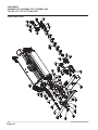
COMMON PARTS - REAR ROLL - Fairway 250 ....................................................................................5
COMMON PARTS - REAR ROLL - Fairway 305, 405, T-Plex 185 series ZX .......................................7
COMMON PARTS - REAR ROLL - T-Plex 185 series ZY ......................................................................9
COMMON PARTS - CYLINDER BEARING HOUSINGS .......................................................................11
COMMON PARTS - CYLINDER BEARING HOUSING ..........................................................................13
COMMON PARTS - BOTTOM BLOCK & CONCAVE ............................................................................15
COMMON PARTS - CONCAVE ..............................................................................................................17
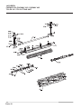
CUTTING CYLINDER & FRONT GROOVED ROLL (FLOATING HEAD)
26" UNIT Fairway 305, 405 & T-Plex 185 series ZX .............................................................................19
CUTTING CYLINDER & FRONT GROOVED ROLL (FLOATING HEAD)
26" UNIT Fairway 305, 405 & T-Plex 185 series ZX .............................................................................21
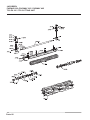
CUTTING CYLINDER & FRONT GROOVED ROLL (FLOATING HEAD)
22" UNIT Fairway 250 ............................................................................................................................23
CUTTING CYLINDER & FRONT GROOVED ROLL 30" Unit T-Plex 185 series ZY ............................25
CUTTING CYLINDER & FRONT GROOVED ROLL 30" Unit T-Plex 185 series ZY ............................27
CUTTING CYLINDER & SKIDS (FIXED HEAD) T-Plex 185 ..................................................................29
CUTTING CYLINDER & FRONT PLAIN ROLL (FLOATING HEAD)
Fairway 250, 305, 405 & T-Plex 185 series ZX .....................................................................................31
CUTTING CYLINDER & FRONT PLAIN ROLL (FLOATING HEAD)
T-Plex 185 series ZY ..............................................................................................................................33
DRIVE ASSEMBLY (ULTRA) .................................................................................................................35
GRASSBOX AND FIXINGS, T-Plex 185 series ZX ..............................................................................37
GRASSBOX AND FIXINGS, Fairway 250, 305, 405 .............................................................................39
CUTTING UNIT & FIXINGS, TR3 LEFT & RIGHT HAND FRONT UNITS .............................................41
CUTTING UNIT & FIXINGS, TR3 CENTRE UNIT ..................................................................................43
GRASSBOX & FIXINGS, TR3 LEFT & RIGHT HAND FRONT UNITS (LMAC193) ..............................45
GRASSBOX & FIXINGS, TR3 CENTRE UNIT (LMAC193) ...................................................................47
TR3 CUTTING UNIT IDENTIFICATION ..................................................................................................49
REAR ROLL BRUSH.......................................................................................................................50 - 57
Parts-1
JACOBSEN
FAIRWAY 250 /FAIRWAY 305 / FAIRWAY 405
T-PLEX 185 / TR3 CUTTING UNIT
Parts-2
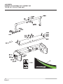
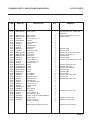
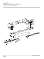
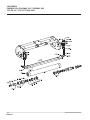
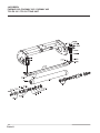
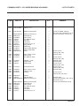
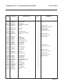
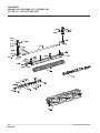
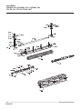
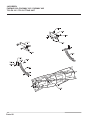
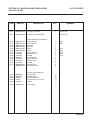
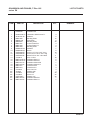
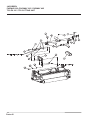
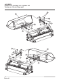
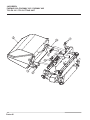
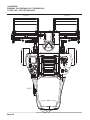
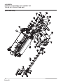
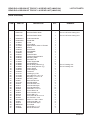
COMMON PARTS - MAIN FRAME & MOUNTING
ITEM
PART NO
2011
MBF1368.06
Main Frame
1
2011
2011
2012
2013
2014
2015
2016
2017
2018*
2019*
2021
2021
2021
2022
2022
2023
2024
2030
2030
2030
2030
2031*
2032
2032
2033
2033
2034
2035
2036
2037
2038
2040
2051
2052
2053
8511
8514
8515*
A
MBF1333.06
MBF1369.06
A128053
GSF2240KT
450724
AF09010
450390
450378
MBF0715
A139917
MBG1508.06
MBG1209.06
MBG2043.06
A119130
A110204
450410
450389
MBF2182.07
2206042B.07
MBF0501B.07
2206004B.07
GSF3014LF
MBE3302
2203001
A100413
450034
450379
450391
A299316
450389
GSF3014LF
A292083
MBE1941A.06
450214
450412
A903494
MBE3628
A149605
Main Frame
Main Frame
Screw No.12 x 13
Spring
Screw M8 x 25
Spacer
Washer 8mm
Stiffnut M8
Stop Bar
Star Ring, 8mm
Top Cover
Top Cover
Top Cover
Screw M6 x 16
Screw M6 x 20
S.L.Washer 6mm
Washer 6mm
Yoke
Yoke
Yoke
Yoke
Bush
Pivot Bush
Pivot Bush
Bolt M10 x 65
Bolt M10 x 60
Stiffnut M10
S.L.Washer 10mm
Lubricator 45°
Washer 6mm
Bush
Disc Spring
Top Plate
Screw M10 x 25
S.L.Washer 10mm
Label - Caution Rotating Blades
Name Plate
Rivet 1/8 x 5/16
Decal - Jacobsen
1
1
2
2
2
2
2
2
1
2
1
1
1
4
4
4
4
1
1
1
1
2
2
2
2
2
2
2
1
1
2
2
1
4
4
1
1
2
1
**
DESCRIPTION
LIST OF PARTS
MBG1508.06 Hinged Concave
* Not Illustrated
QTY
REMARKS
(Fairway 305, 405, T-Plex 185
series ZX)
(T-Plex 185 series ZY & TR3)
(Fairway 250)
(Fairway 250)
(Fairway 250)
(T-Plex 185 series ZX & TR3) **
(T-Plex 185 series ZY)
(Fairway 250)
(Fairway 250)
(T-Plex 185 & Fairway 305, 405)
(T-Plex 185 series ZX))
(Fairway 305, 405)
(T-Plex 185 series ZY)
(Fairway 250)
(Fairway 250)
(T-Plex 185)
(Fairway 250, 305, 405)
(T-Plex 185)
(Fairway 250, 305, 405)
(Fairway 250, 305, 405)
(Used on T-Plex only)
(Used on T-Plex only)
Also fits F/W 205 & 405
Parts-3
JACOBSEN
FAIRWAY 250 /FAIRWAY 305 / FAIRWAY 405
T-PLEX 185 / TR3 CUTTING UNIT
Parts-4
COMMON PARTS - REAR ROLL - Fairway 250
ITEM
PART NO
3011
3012
3013
3014
3015
3016
3017
3018
3019
3020
3021
3022
3023
3024
3026
3028
3035
3036
3037
3038
3055
3056
3057
3058
3065*
3066*
LMSE121
MBF0818
MBG2045
MBF0001
A230013
A291115
A205929
MBE2429
A220254
451982
MBE2430
A221137
A299301
MBE2431B
450334
A230021
MBF0002
MBE3986
452565
450378
450390
MBE3982A
MBE4001
452464
MBE4017
A906742
450323
**
450334
DESCRIPTION
Plain Roll Assy.
• Roller Tube
• Spindle
• Ring Carrier
• Seal Ring
• Compression Spring
• Taper Roller Bearing
• Bearing Housing
• Rotary Lip Seal
• Circlip
• Seal Journal
• O Ring
• Lubricator
• Shield
• Thin Nut M16
• Seal Ring
• Washer
Housing - Rear
Bolt M8 x 30
Stiffnut M8
Washer 8mm
Carriage - Rear
Carriage Nut **
Screw M8 x 16
Carriage Nut
Scraper Cable
Nut M6
LIST OF PARTS
QTY
1
1
1
2
1
2
2
2
2
2
2
4
2
2
4
1
2
2
4
4
4
2
2
2
2
1
2
REMARKS
A230021 Seal Ring
Nut M16 Thin
* Not Illustrated
Parts-5
JACOBSEN
FAIRWAY 250 /FAIRWAY 305 / FAIRWAY 405
T-PLEX 185 / TR3 CUTTING UNIT
Parts-6
COMMON PARTS - REAR ROLL - Fairway 305, 405,
T-Plex 185 series ZX
TR
ITEM
3011
3012
3013
3014
3015
3016
3017
3018
3019
3020
3021
3022
3023
3024
3026
3028
3035
3036
3037
3038
3055
3056
3057
3058
3065*
3066*
PART NO
MBE1761D
MBE1752C
MBF0001
A230013
A291115
A205929
MBE2429
A220254
451982
MBE2430
A221137
A299301
MBE2431B
450334
A230021
MBF0002
MBE3986
452565
450378
450390
MBE3982A
MBE4001
452464
MBE4017
A906704
450323
DESCRIPTION
Plain Roll Assy.
• Roller Tube
• Spindle
• Ring Carrier
• Seal Ring
• Compression Spring
• Taper Roller Bearing
• Bearing Housing
• Rotary Lip Seal
• Circlip
• Seal Journal
• O Ring
• Lubricator
• Shield
• Thin Nut M16
• Seal Ring
• Washer
Housing - Rear
Bolt M8 x 30
Stiffnut M8
Washer 8mm
Carriage - Rear
Carriage Nut
Screw M8 x 16
Carriage Nut
Scraper Cable
Nut M6
* Not Illustrated
LIST OF PARTS
QTY
REMARKS
1
1
1
2
1
2
2
2
2
2
2
4
2
2
4
1
2
2
4
4
4
2
2
2
2
1
2
Parts-7
JACOBSEN
FAIRWAY 250 /FAIRWAY 305 / FAIRWAY 405
T-PLEX 185 / TR3 CUTTING UNIT
Parts-8
COMMON PARTS - REAR ROLL - T-Plex 185 series ZY
ITEM
PART NO
3011
3012
3013
3014
3015
3016
3017
3018
3019
3020
MBF0486
MBG1210
MBF0001
A230013
A291115
A205929
MBE2429
A220254
451982
MBE2430
MBE1372
450326
A221910
A221137
A299301
MBE2431B
450334
A230021
MBF0002
MBE3986
A102306
A133208
A150008
MBE3982
MBE4001
A114395
MBE4017
A906732
A130006
MBG3645.06
3021
3022
3023
3024
3026
3028
3035
3036
3037
3038
3055
3056
3057
3058
3065*
3066*
*
DESCRIPTION
Plain Roll Assy.
• Roller Tube
• Spindle
• Ring Carrier
• Seal Ring
• Compression Spring
• Taper Roller Bearing
• Bearing Housing
• Rotary Lip Seal
• Circlip
• Seal Journal
• Washer
• Nut M12
• O Ring
• O Ring
• Lubricator
• Shield
• Nut M16 thin
• Seal Ring
• Washer
Housing - Rear
Bolt M8 x 30
Stiffnut M8
Washer 8mm
Carriage - Rear
Carriage Nut
Screw M8 x 16
Carriage Nut
Scraper Cable
Nut M6
Adapter Plate
* Not Illustrated
LIST OF PARTS
QTY
REMARKS
1
1
1
2
1
2
2
2
2
2
2
2
2
4
4
2
2
4
1
2
2
4
4
4
2
2
2
2
1
2
1
Parts-9
JACOBSEN
FAIRWAY 250 /FAIRWAY 305 / FAIRWAY 405
T-PLEX 185 / TR3 CUTTING UNIT
Parts-10
COMMON PARTS - CYLINDER BEARING HOUSINGS
DESCRIPTION
LIST OF PARTS
ITEM
PART NO
8513
GSF3702SZ
Label (+<->-)
2
9011
2201002.06
Bearing Housing RH
1
*
9012
9013
9014
9015
9016
9017
9018
9019
9020
9021
9022
MBG1696.06
MBC7671
H083023
450412
450325
A299301
451153
MBE2231
A230013
A209044
A230019
MBE2374B
Bearing Housing LH
Shoulder pin
Disc Spring
S.L.Washer 10mm
Nut M10
Lubricator
Screw No.12 x 13
Ring Carrier
Seal Ring
Taper Roller Bearing
Rotary Shaft Seal
Stud
1
1
1
1
1
1
1
1
1
1
1
1
9022
9023
9024
2203038
A292083
A151010
Stud, 10mm / 8mm
Disc Spring
S.L.Washer 10mm
1
1
2
9024
9025
9025
A159401
450379
450379
Washer , 0.328
Stiffnut M10
Stiffnut M10
2
1
1
9026
A110406
Screw M10 x 30
1
9026
9027
9028
2203039
A199302
A221031
Stud, 10mm / 8mm
Helicoil Insert
O Ring
1
3
1
9029
9030
9031
MBE4676
450378
MBE2982B.06
Spacer
Nut, M8 Nyloc
Bearing Housing LH
1
1
1
*
9032
9033
9034
9035
9036
9037
MBG1694.06
MBC7671
H083023
450412
450325
A299301
451153
Bearing Housing RH
Shoulder Pin
Disc Spring
S.L.Washer 10mm
Nut M10
Lubricator
Screw No.12 x 13
1
1
1
1
1
1
1
* Not Illustrated
QTY
REMARKS
(T-Plex 185 RHD, Fairway
250, 305, 405 & TR3 Units 1 & 3)
(T-Plex 185 LHD & TR3 Unit 2)
(T-Plex 185 &
Fairway 305, 405)
(Fairway 250)
(T-Plex 185 &
Fairway 305, 405)
(Fairway 250)
(Fairway 250)
(T-Plex 185 &
Fairway 305, 405)
(T-Plex 185 &
Fairway 305, 405)
(Fairway 250)
(T-Plex 185 &
Fairway 250, 305, 405)
(Fairway 250)
(T-Plex 185, Fairway 305, 405 &
TR3 Units 1 & 3)
(T-Plex 185 LHD &TR3 Unit 2)
Parts-11
JACOBSEN
FAIRWAY 250 /FAIRWAY 305 / FAIRWAY 405
T-PLEX 185 / TR3 CUTTING UNIT
Parts-12
COMMON PARTS - CYLINDER BEARING HOUSING
ITEM
PART NO
DESCRIPTION
LIST OF PARTS
QTY
9038
9039
9040
9042
MBE2231
A230013
A209044
MBC9175
Ring Carrier
Seal Ring
Taper Roller Bearing
Plunger
1
1
1
1
9042
9043
MBG1392
MBC9178
Plunger
Guide
1
1
9044
9045
9046
450393
A291094
MBC9177
Washer 16mm
Compression Spring
Plate
1
1
1
9046
9047
9048
9049
9050
9051
9052
9061
MBF0544
450005
450377
450217
450412
A292083
450379
MBF0324
Plate
Bolt M6 x 50
Stiffnut M6
Screw M10 x 40
S.L.Washer 10mm
Disc Spring
Stiffnut M10
Abutment
1
1
1
1
1
1
1
2
9062
9063
9064
450170
A292028
2201011
Screw M6 x 16
Disc Spring
Abutment
4
4
2
9065
9066
MBE2969
MBC9251
Adjuster
Spacer Collar
2
2
9066
9067
9068
9069
9070
9071
9072
9073
9075
9079
9080
9081
450393
450382
A299054
A291093
A189420
452042
A249111
MBE3222A
A221026
MBE2659
450332
MBC9642
Washer M16
Stiffnut M16
Handwheel
Compression Spring
Nylon Washer
Circlip
Screw Plug
Adjuster Rod
O Ring
Pivot Stud
Thin Nut M10
Shim
2
2
2
2
2
2
2
2
2
2
2
4
* Not Illustrated
REMARKS
(T-Plex 185 &
Fairway 250, 305, 405)
(Fairway 250)
(T-Plex 185 &
Fairway 305, 405)
(T-Plex 185 &
Fairway 305, 405)
(Fairway 250)
(T-Plex 185 &
Fairway 305, 405)
(T-Plex 185 &
Fairway 305, 405)
(T-Plex 185 &
Fairway 305, 405)
(Fairway 250)
Parts-13
JACOBSEN
FAIRWAY 250 /FAIRWAY 305 / FAIRWAY 405
T-PLEX 185 / TR3 CUTTING UNIT
Parts-14
COMMON PARTS - BOTTOM BLOCK & CONCAVE
DESCRIPTION
LIST OF PARTS
ITEM
PART NO
9091
LMAB533.07
Bottom Block Assy (26")
1
9091.2
9091.3
9091.4
9091.5
9091.6
9091.7
9091.8
MBA7103
A119001
A913440
450532
450388
450322
N/A
Bottom Blade
Screw
Wood Fillet
Screw M5 x 35
Washer 5mm
Nut M5
Bottom Block
1
11
1
3
3
3
1
9091
LMAB535.07
Bottom Block Assy (30")
1
9091.2
9091.3
9091.4
9091.5
9091.6
9091.7
9091.8
MBA7109
A119001
A913461
450532
450388
450322
N/A
Bottom Blade
Screw
Plastic Fillet
Screw M5 x 35
Washer 5mm
Nut M5
Bottom Block
1
11
1
3
3
3
1
9091
LMAB534.07
Bottom Block Assy (22")
1
9091.2
9091.3
9091.4
9091.5
9091.6
9091.7
9091.8
MBA7116A
A119001
A913466
450532
450388
450322
N/A
Bottom Blade
Screw
Wood Fillet
Screw M5 x 35
Washer 5mm
Nut M5
Bottom Block
1
11
1
3
3
3
1
9097
9099
9112
9113
9114
9115
9120
9121
9122
9123
9124
9125*
9126
450865
450879
MBE1967
450170
450389
450377
MBF0489.06
MBF0492.06
A100318
A292050
A150008
030314301
A912009
Screw M8 x 20
Screw M10 x 20
Clamp Bracket
Screw M6 x 16
Washer 6mm
Stiffnut M6
Concave Top
Concave Base
Bolt M8 x 90
Disc spring
8mm Washer
Anti-seize spray
Rubber washer
4
2
4
4
4
4
1
1
2
2
11
A/R
1
*
MBA7096A
MBG0578A
Bottom blade (Thin)
Concave WLDMT/Assy
* Not Illustrated
QTY
1
REMARKS
(Fairway 305, 405
T-Plex 185 series ZX & TR3)
(Floating Head only T-Plex 185
series ZY)
(Fairway 250)
(T-Plex 185 x 30" C/U)
(T-Plex 185 x 30" C/U)
(Fairway 305, 405 )
Piano Type Hinge
Parts-15
JACOBSEN
FAIRWAY 250 /FAIRWAY 305 / FAIRWAY 405
T-PLEX 185 / TR3 CUTTING UNIT
Parts-16
COMMON PARTS - CONCAVE
ITEM
PART NO
LIST OF PARTS
DESCRIPTION
QTY
9091
9091.2
9091.3
9091.4
9091.5
9091.6
9091.7
9091.8
LMAB533.07
MBA7103
A119001
A913440
450532
450388
450322
N/A
Bottom Block Assy (26")
Bottom Blade
Screw
Wood Fillet
Screw M5 x 35
Washer 5mm
Nut M5
Bottom Block
1
1
11
1
3
3
3
1
*
MBA7096A
Bottom blade (Thin)
1
9097
9099
9112
9113
9114
9115
450865
450879
MBE1967
450170
450389
450377
Screw M8 x 20
Screw M10 x 20
Clamp Bracket
Screw M6 x 16
Washer 6mm
Stiffnut M6
4
2
4
4
4
4
9160
9160
9161
9162
9163
9164
9170
9171
9172
9173
9180
9181
9182
9183
9184
9185
9186
9187
9188
MBF0578C.06
MBF0820.06
2202027
450190
450378
450390
450023
450378
450390
AF9020
MBE1969
A291070
AF09006
MBE1970A
451344
AF09006
MBE1980B
450390
451208
Wldmt - Concave
Wldmt - Concave
Lever
Screw, M8 x 16
Nut, M8 Nyloc
Washer, M8
Bolt, M8 x 75
Nut, M8 Nyloc
Washer, M8
Spacer
Clevis
Spring
Spacer
Eye Rod
Spirol Pin
Spacer
Pivot Pin
Washer, M8
Split Pin 2 x 14
1
1
1
2
2
2
1
1
4
2
1
1
1
1
1
2
1
2
2
* Not Illustrated
REMARKS
(T-Plex 185 ZX & TR3)
(Fairway 250)
Parts-17
JACOBSEN
FAIRWAY 250 /FAIRWAY 305 / FAIRWAY 405
T-PLEX 185 / TR3 CUTTING UNIT
Parts-18
CUTTING CYLINDER & FRONT GROOVED ROLL (FLOATING HEAD)
26" UNIT
Fairway 305, 405 & T-Plex 185 series ZX
ITEM
PART NO
3011
3012
3013
3014
3015
3016
3017
3018
3019
3020
3021
3022
3023
3024
3026
3028
3035
3036
3037
3038
3045
3046
3047
3048
3055
3056
3057
3065
3066
3067
3068
3069
3070
3071
3072
3073
3074
JMSE118
MBG1594
MBE1752B
MBF0001
A230013
A291115
A205929
MBE2429
A220254
451982
MBE2430
A221137
A299301
MBE2431
450334
A230021
MBF0002
MBE3984
452565
450378
450390
MBE3985
452565
450378
450390
MBE3982
MBE4001
452464
MBG1982
MBE3791
450170
450410
MBE4333A
MBE4334A
450002
450003
450377
450389
DESCRIPTION
Grooved Roll Assy.
Roll Tube
Spindle
Ring Carrier
Seal Ring
Compression Spring
Taper Roller Bearing
Bearing Housing
Rotary Lip Seal
Circlip
Seal Journal
O Ring
Lubricator
Shield
Thin Nut M16
Seal Ring
Washer
Housing Front LH
Bolt M8 x 30
Stiffnut M8
Washer 8mm
Housing Front RH
Bolt M8 x 30
Stiffnut M8
Washer 8mm
Carriage Front
Carriage Nut
Screw M8 x 16
Scraper
Carrier W/Assy
Screw M6 x 16
Dia 6 Lock Washer
LH Scraper Bracket
RH Scraper Bracket
Bolt M6 x 35
Bolt M6 x 40
M6 Staytite Nut
Washer 6mm
* Not Illustrated
QTY
LIST OF PARTS
REMARKS
1
1
1
2
1
2
2
2
2
2
2
4
2
2
4
1
2
1
1
1
1
1
1
1
1
2
4
2
1
1
4
4
1
1
2
2
4
12
Parts-19
JACOBSEN
FAIRWAY 250 /FAIRWAY 305 / FAIRWAY 405
T-PLEX 185 / TR3 CUTTING UNIT
Parts-20
CUTTING CYLINDER & FRONT GROOVED ROLL (FLOATING HEAD)
26" UNIT
Fairway 305, 405 & T-Plex 185 series ZX
ITEM
PART NO
DESCRIPTION
QTY
LIST OF PARTS
REMARKS
9011
MBF0325B.07
Cutting Cylinder 7K Tang Drive
1
(T-Plex 185 series ZX
Fairway 305, 405)
9011*
MBF0326B.07
Cutting Cylinder 11K Tang Drive
*
MBF0895A.07
(T-Plex 185 series ZX
Fairway 305, 405)
(T-Plex 185 with 26" Units)
*
MBF0896A.07
Cylinder-26" x 7K, LHD Tang
Tang Drive LH
Cylinder-26" x 11K, LHD Tang
Tang Drive LH
1
1
1
1
(T-Plex 185 with 26" Units)
* Not Illustrated
Parts-21
JACOBSEN
FAIRWAY 250 /FAIRWAY 305 / FAIRWAY 405
T-PLEX 185 / TR3 CUTTING UNIT
Parts-22
CUTTING CYLINDER & FRONT GROOVED ROLL (FLOATING HEAD)
22" UNIT
Fairway 250
ITEM
PART NO
DESCRIPTION
3011
3012
3013
3014
3015
3016
3017
3018
3019
3020
3021
3022
3023
3024
3026
3028
3035
3036
3037
3038
3045
3046
3047
3048
3055
3056
3057
3065
3066
3067
3068
3069
3070
3071
3072
3073
3074
JMSE120
MBG2051
MBG2045
MBF0001
A230013
A291115
A205929
MBE2429
A220254
451982
MBE2430
A221137
A299301
MBE2431B
450334
A230021
MBF0002
MBE3984
452565
450378
450390
MBE3985
452565
450378
450390
MBE3982A
MBE4001
452464
MBG2052
MBF0823
450170
450410
MBE4333A
MBE4334A
450002
450003
450377
450389
Grooved Roll Assy.
Roll Tube
Spindle
Ring Carrier
Seal Ring
Compression Spring
Taper Roller Bearing
Bearing Housing
Rotary Lip Seal
Circlip
Seal Journal
O Ring
Lubricator
Shield
Thin Nut M16
Seal Ring
Washer
Housing Front LH
Bolt M8 x 30
Stiffnut M8
Washer 8mm
Housing Front RH
Bolt M8 x 30
Stiffnut M8
Washer 8mm
Carriage Front
Carriage Nut
Screw M8 x 16
Scraper
Carrier W/Assy
Screw M6 x 16
Dia 6 Lock Washer
LH Scraper Bracket
RH Scraper Bracket
Bolt M6 x 35
Bolt M6 x 40
M6 Staytite Nut
Washer 6mm
1
1
1
2
1
2
2
2
2
2
2
4
2
2
4
1
2
1
1
1
1
1
1
1
1
2
4
2
1
1
4
4
1
1
2
2
4
12
9011
MBF0821B.07
Cutting Cylinder 7K
1
9011*
MBF0822B.07
Cutting Cylinder 11K
1
* Not Illustrated
QTY
LIST OF PARTS
REMARKS
Parts-23
JACOBSEN
FAIRWAY 250 /FAIRWAY 305 / FAIRWAY 405
T-PLEX 185 / TR3 CUTTING UNIT
Parts-24
CUTTING CYLINDER & FRONT GROOVED ROLL 30" Unit
T-Plex 185 series ZY
ITEM
PART NO
DESCRIPTION
3011
3012
3013
3014
3015
3016
3017
3018
3019
3020
3021
3022
3023
3024
3026
3028
3035
3036
3037
3038
3045
3046
3047
3048
3055
3056
3057
3065
3066
3067
3068
3069
3070
3071
3072
3073
3074
JMSE119
MBG1901
MBG1210
MBF0001
A230013
A291115
A205929
MBE2429
A220254
A170052
MBE2430
A221137
A299301
MBE2431B
A130116
A230021
MBF0002
MBE3984
A102306
A133208
A150008
MBE3985
A12306
A133208
A150008
MBE3982
MBE4001
A114395
MBG1983
MBF0499
A110296
A151006
MBE4333A
MBE4334A
A100207
A100208
A133206
A150006
9011
MBF0483 B.07 Cutting Cylinder 7k RHD
1
*
*
MBF0597A.06 Front Skid LH
MBF0671 B.07 Cutting Cylinder 7k LHD
1
Grooved Roll Assy.
Roll Tube
Spindle
Ring Carrier
Seal Ring
Compression Spring
Taper Roller Bearing
Bearing Housing
Rotary Lip Seal
Circlip
Seal Journal
O Ring
Lubricator
Shield
Thin Nut M16
Seal Ring
Washer
Housing Front LH
Bolt M8 x 30
Stiffnut M8
Washer 8mm
Housing Front RH
Bolt M8 x 30
Stiffnut M8
Washer 8mm
Carriage Front
Carriage Nut
Screw M8 x 16
Scraper
Carrier W/Assy
Screw M6 x 16
Dia 6 Lock Washer
LH Scraper Bracket
RH Scraper Bracket
Bolt M6 x 35
Bolt M6 x 40
M6 Staytite Nut
Washer 6mm
* Not Illustrated
QTY
LIST OF PARTS
REMARKS
1
1
1
2
1
2
2
2
2
2
2
4
2
2
4
1
2
1
1
1
1
1
1
1
1
2
4
2
1
1
4
4
1
1
2
2
4
12
Parts-25
JACOBSEN
FAIRWAY 250 /FAIRWAY 305 / FAIRWAY 405
T-PLEX 185 / TR3 CUTTING UNIT
Parts-26
CUTTING CYLINDER & FRONT GROOVED ROLL 30" Unit
T-Plex 185 series ZY
ITEM
PART NO
DESCRIPTION
9011
MBF0484B.07
Cutting Cylinder 11k RHD
1
*
MBF0677B.07
Cutting Cylinder 11k LHD
1
* Not Illustrated
QTY
LIST OF PARTS
REMARKS
Parts-27
JACOBSEN
FAIRWAY 250 /FAIRWAY 305 / FAIRWAY 405
T-PLEX 185 / TR3 CUTTING UNIT
Parts-28
CUTTING CYLINDER & SKIDS (FIXED HEAD)
T-Plex 185 & TR3
DESCRIPTION
LIST OF PARTS
ITEM
PART NO
9127
MBF0469B.07
Cutting Cylinder 5K
1
T-Plex 185
9127
MBF0482B.07
Cutting Cylinder 5K RHD
1
T-Plex 185
9130
9131
9132
9133
9134
9135
9136
9137
9138
9139
9140
9141
9142
9143
*
MBE0092.06
MBE0093.06
MBG1065.06
MBG1065.06
MBG1067.06
MBG1068.06
A110204
A150006
A130006
MBF0411
A110305
A150008
A133208
MBG0958.06
MBC8985.06
Fixed Head Skids & Restraint
Front Skid RH
Front Skid LH
Strut RH
Strut LH
Plate
Collar
Screw M6 x 20
Washer 6mm
Nut M6
Shoulder Bolt
Screw M8 x 25
Washer 8mm
Nut M8
Anchor Plate
Skid-Heavy Duty
1
1
1
1
2
2
4
4
4
2
2
2
2
2
2
TR3
TR3
6250*
6251*
6252*
6253*
6255*
MBG0958
MBF0411
450378
450411
A906071
Floating Head Restraint
Anchor Plate
Shoulder Bolt
Nut-hex M8 Nyloc
Lockwshr-m8 X 12.75 X 2
Cable
6
12
6
6
6
6261*
LMSD933A
Hoc Guage.
* Not Illustrated
QTY
REMARKS
TR3
TR3
TR3
TR3
TR3
1
Parts-29
JACOBSEN
FAIRWAY 250 /FAIRWAY 305 / FAIRWAY 405
T-PLEX 185 / TR3 CUTTING UNIT
Parts-30
CUTTING CYLINDER & FRONT PLAIN ROLL (FLOATING HEAD)
Fairway 250, 305, 405 & T-Plex 185 series ZX
DESCRIPTION
ITEM
PART NO
Plain Roll Assy.
Plain Roll Assy.
• Roll Tube
• Roll Tube
• Spindle
• Spindle
• Ring Carrier
• Seal Ring
• Compression Spring
• Taper Roller Bearing
• Bearing Housing
• Rotary Lip Seal
• Circlip
• Seal Journal
• O Ring
• Lubricator
• Shield
• Thin Nut M16
• Seal Ring
• Washer
Housing Front LH
Bolt M8 x 30
Stiffnut M8
Washer 8mm
Housing Front RH
Bolt M8 x 30
Stiffnut M8
Washer 8mm
Carriage Front
Carriage Nut
Screw M8 x 16
Scraper Cable
Nut M6
1
1
1
1
1
1
2
1
2
2
2
2
2
2
4
2
2
4
1
2
1
1
1
1
1
1
1
1
2
4
2
1
2
Fairway 305, 405 & T-Plex 185 series ZX
Fairway 250
3011
3011
3012
3012
3013
3014
3015
3016
3017
3018
3019
3020
3021
3022
3023
3024
3026
3028
3035
3036
3037
3038
3045
3046
3047
3048
3055
3056
3057
3065
3066
JMSE079
JMSE121
MBE1761D
MBF0818
MBE1752B
MBG2045
MBF0001
A230013
A291115
A205929
MBE2429
A220254
451982
MBE2430
A221137
A299301
MBE2431B
450334
A230021
MBF0002
MBE3984
A102306
A133208
A150008
MBE3985
A102306
A133208
A150008
MBE3982
MBE4001
A114395
A906704
A130006
9011
9011
MBF0469B.07
MBF0325B.07
Cutting Cylinder 5K
Cutting Cylinder 7K
1
1
9011
MBF0326B.07
Cutting Cylinder 11K
1
(T-Plex 185 series ZX/RHD)
(T-Plex 185 series ZX /RHD &
Fairway 305, 405)
(T-Plex 185 series ZX /RHD &
Fairway 305, 405)
9011
9011
9011
MBF0894A.07
MBF0895A.07
MBF0896A.07
Cutting Cylinder 5K
Cutting Cylinder 7K
Cutting Cylinder 11K
1
1
1
* Not Illustrated
QTY
LIST OF PARTS
REMARKS
Fairway 305, 405 & T-Plex 185 series ZX
Fairway 250
Fairway 305, 405 & T-Plex 185 series ZX
Fairway 250
(T-Plex 185 series ZX/LHD
(T-Plex 185 series ZX/LHD
(T-Plex 185 series ZX/LHD
Parts-31
JACOBSEN
FAIRWAY 250 /FAIRWAY 305 / FAIRWAY 405
T-PLEX 185 / TR3 CUTTING UNIT
Parts-32
CUTTING CYLINDER & FRONT PLAIN ROLL (FLOATING HEAD)
T-Plex 185 series ZY
ITEM
PART NO
DESCRIPTION
3011
3012
3013
3014
3015
3016
3017
3018
3019
3020
3021
3022
3023
3024
3026
3028
3035
3036
3037
3038
3045
3046
3047
3048
3055
3056
3057
3065
3066
MBF0486
MBG1210
MBF0001
A230013
A291115
A205929
MBE2429
A220254
451982
MBE2430
A221137
A299301
MBE2431B
450334
A230021
MBF0002
MBE3984
452565
450378
450390
MBE3985
452565
450378
450390
MBE3982
MBE4001
452464
A906732
450323
Plain Roll Assy.
• Roll Tube
• Spindle
• Ring Carrier
• Seal Ring
• Compression Spring
• Taper Roller Bearing
• Bearing Housing
• Rotary Lip Seal
• Circlip
• Seal Journal
• O Ring
• Lubricator
• Shield
• Thin Nut M16
• Seal Ring
• Washer
Housing Front LH
Bolt M8 x 30
Stiffnut M8
Washer 8mm
Housing Front RH
Bolt M8 x 30
Stiffnut M8
Washer 8mm
Carriage Front
Carriage Nut
Screw M8 x 16
Scraper cable
Nut M6
1
1
1
2
1
2
2
2
2
2
2
4
2
2
4
1
2
1
1
1
1
1
1
1
1
2
4
2
1
2
9011
MBF0483B.07
Cutting Cylinder 7k RHD
1
*
MBF0671B.07
Cutting Cylinder 7k LHD
1
9011
MBF0484B.07
Cutting Cylinder 11k RHD
1
*
MBF0677B.07
Cutting Cylinder 11k LHD
1
* Not Illustrated
QTY
LIST OF PARTS
REMARKS
Parts-33
JACOBSEN
FAIRWAY 250 /FAIRWAY 305 / FAIRWAY 405
T-PLEX 185 / TR3 CUTTING UNIT
Parts-34
DRIVE ASSEMBLY (ULTRA)
ITEM
PART NO
LIST OF PARTS
DESCRIPTION
QTY
1
1
2
3
*
A800070
A800621
A221031
A808914
A809615
T-Plex 185 series ZX/ZY
Hydraulic Motor
Hydraulic Motor
Sealing O ' Ring
Drive Coupling (Tang)
Seal Kit
1
1
1
1
1
1
2
3
*
A800040
A221031
A808914
A809615
Fairway 305
Hydraulic Motor
Sealing O ' Ring
Drive Coupling (Tang)
Seal Kit
1
1
1
1
1
2
3
*
A800041
A221031
A808914
A809615
Fairway 305
Hydraulic Motor
Sealing O ' Ring
Drive Coupling (Tang)
Seal Kit
1
1
1
1
1
2
3
*
W2208040
A221031
A808914
A809615
Fairway 405 / Fairway 250
Hydraulic Motor
Sealing O ' Ring
Drive Coupling (Tang)
Seal Kit
1
1
1
1
1
2
3
*
W2208062
A221031
A808914
A809615
Fairway 405 / Fairway 250
Hydraulic Motor
Sealing O ' Ring
Drive Coupling (Tang)
Seal Kit
1
1
1
1
1
2
3
*
4140034
A221031
MBF1273A
A809615
TR3
Hydraulic Motor
Sealing O ' Ring
Drive Coupling (Tang)
Seal Kit
1
1
1
1
* Not Illustrated
REMARKS
T-Plex 185 series ZX, RHD / ZY
T-Plex 185 series ZX, LHD
Parts-35
JACOBSEN
FAIRWAY 250 /FAIRWAY 305 / FAIRWAY 405
T-PLEX 185 / TR3 CUTTING UNIT
Parts-36
GRASSBOX AND FIXINGS, T-Plex 185
series ZX
ITEM
1
2
3
4
5
6
7
8
9
10
11
12
13
14
15
16
17
18
19
20
21
23*
24*
25*
26*
27*
28*
PART NO
DESCRIPTION
LMAB484
Grassbox Kit
699533788.11
W106172.06
MBC1629
MBC8114a
MBC8940
MBC1617
MBC1618
MBC1630
BAM2245.06
BAM2288.06
GSF2093AD
GSF2093CD
GSF2091CK
A139912
MBF1318A.07
MBF1321A.07
MBF1337.07
MBF1336.07
MBF1341
MBF1343
A139322
450390
A149623
A149622
GSF2150C
MBF1789.07
MBF1790.07
Grass Box With Screen Fr.
Stiffener
Backing Plate
Stop Plate
Backing Plate
Corner Plate R.H.
Corner Plate L.H.
Backing Plate
Stiffener
Brace
Screw, 1/4" Unc X 3/4" Long
Screw, 5/16" Unc X 3/4" Long
Bolt 5/16"Unc X 2" Hex Head
Nut, 1/4 Unc
Grassbox Brkt LH
Grassbox Brkt RH
Grassbox Mount RH
Grassbox Mount LH
Hook-front Rh
Hook-front Lh
Nut, 5/16 Unc
Washer, M8
Rivet 3/16"
Rivet 1/4"
Washer 1/4"
Grassbox Brkt RH
Grassbox Brkt LH
* Not Illustrated
LIST OF PARTS
QTY
REMARKS
3
2
12
6
30
3
3
6
1
6
18
4
4
18
2
2
1
1
3
3
4
4
30
42
42
1
1
Parts-37
JACOBSEN
FAIRWAY 250 /FAIRWAY 305 / FAIRWAY 405
T-PLEX 185 / TR3 CUTTING UNIT
Parts-38
GRASSBOX AND FIXINGS, Fairway 250, 305, 405
ITEM
1
2
3
4
5
6
7
8
9
10
11
12
13
14
15
15
16
17
PART NO
2208014
2202019
2203029
2208015
64163-29
A151008
A100307
64061-34
2203030
64215-03
2202024
64211-02
64163-61
A110404
2208016.11
2208095.11
2202023
2206042B.07
DESCRIPTION
Latch Spring Lh
Latch Catcher
Bushing
Latch Spring Rh
Washer
S.l.washer
Bolt M8 X 35
Roll Pin
Pin Catcher
Pop Rivet
Plate
Washer
Washer
Screw M10 X 20
Grass Box 22" - Grey
Grass Box 26" - Grey
Plate-Catcher RH
Yoke
* Not Illustrated
LIST OF PARTS
QTY
REMARKS
1
2
2
2
2
2
2
2
2
8
1
8
2
2
1
1
1
1
Parts-39
JACOBSEN
FAIRWAY 250 /FAIRWAY 305 / FAIRWAY 405
T-PLEX 185 / TR3 CUTTING UNIT
Parts-40
CUTTING UNIT FIXINGS, TR3 LEFT & RIGHT
HAND FRONT UNITS
ITEM
PART NO
DESCRIPTION
LIST OF PARTS
QTY
REMARKS
Pivot Arm Left Hand Front
1
2
3
4
5
6
7
8
9
10
11
12
13
001399032
001599052
002993013
4139256
4139281
4139349
4139374
450215
450216
450379
450391
450412
456010577
Nut-Hex 1/2-20 Nyloc
Washer- .526-.506 x 1-1/4 x 12GA
Lubricator - M6 STR
Wldmt-Pivot Arm Left Hand
Bracket-Left Hand Pivot Arm
Bracket-Right Hand Pivot Arm
Spacer-1/2 x 3/4 x 1/2
Screw-Hex M10 x 30
Screw-Hex M10 x 35
Nut-Hex M10 Nyloc
Washer-M10 x 21 x 2.2
Washer-SLW M10
Screw-Hex 1/2-20 x 1-1/2
2
2
1
1
1
1
2
4
2
2
6
4
2
Pivot Arm Right Hand Front
1
2
3
4
5
6
7
8
9
10
11
12
13
001399032
001599052
002993013
4139257
4139281
4139349
4139374
450215
450216
450379
450391
450412
456010577
Nut-Hex 1/2-20 Nyloc
Washer- .526-.506 x 1-1/4 x 12GA
Lubricator - M6 STR
Wldmt-Pivot Arm Right Hand
Bracket-Left Hand Pivot Arm
Bracket-Right Hand Pivot Arm
Spacer-1/2 x 3/4 x 1/2
Screw-Hex M10 x 30
Screw-Hex M10 x 35
Nut-Hex M10 Nyloc
Washer-M10 x 21 x 2.2
Washer-SLW M10
Screw-Hex 1/2-20 x 1-1/2
* Not Illustrated
2
2
1
1
1
1
2
4
2
2
6
4
2
Parts-41
JACOBSEN
FAIRWAY 250 /FAIRWAY 305 / FAIRWAY 405
T-PLEX 185 / TR3 CUTTING UNIT
Parts-42
CUTTING UNIT FIXINGS, TR3 CENTRE UNITS
ITEM
PART NO
DESCRIPTION
LIST OF PARTS
QTY
REMARKS
Pivot Arm Centre Unit
1
2
3
4
5
6
7
8
9
10
11
12
13
14
15
16
17
18
19
20
001399032
001399105
001599052
002993160
4139374
4139591
4140077
4140078
4142386
450215
450216
4139923
450391
450412
452000326
456010420
456010577
J361723
450379
450120398
Nut-Hex 1/2-20 Nyloc
Nut-Hex 3/8-24 Nyloc
Washer- .526-.506 x 1-1/4 x 12GA
Lubricator M6 x 90 deg
Spacer-1/2 x 3/4 x 1/2
Wldmt-Pivot Arm Centre Deck
Bracket-Left Hand Centre Pivot
Bracket-Right Hand Centre Pivot
Bracket-Centre Unit Stop
Screw-Hex M10 x 30
Screw-Hex M10 x 35
Centre Unit Bump Bracket
Washer-M10 x 21 x 2.2
Washer-SLW M10
Washer - 3/8 x 3/4 x .072
Screw-Hex 3/8-24 x 1-1/2
Screw-Hex 1/2-20 x 1-1/2
Bump Stop
Nut-Hex M10 Nyloc
Nut-Hex 3/8-16 Nyloc Thin
* Not Illustrated
2
4
2
1
2
1
1
1
1
4
2
1
6
4
8
4
2
1
2
1
Parts-43
JACOBSEN
FAIRWAY 250 /FAIRWAY 305 / FAIRWAY 405
T-PLEX 185 / TR3 CUTTING UNIT
Parts-44
GRASSBOX AND FIXINGS, TR3 LEFT & RIGHT
HAND FRONT UNITS (LMAC193)
ITEM
LIST OF PARTS
PART NO
DESCRIPTION
1
2
3
4
5
6
7
4139527
4139528
450002
450389
450410
3007844
002952722
Left Hand Front Grassbox
Wldmt-Grassbox Arm LH Outer
Wldmt-Grassbox Arm LH Inner
Bolt-Hex M6 x 35
Washer-M6 x 12.5 x 1.8
Washer-SLW M6
Grassbox
End Cap-22 x 22 x 2
1
1
4
4
4
1
2
1
2
3
4
5
6
7
4139529
4139530
450002
450389
450410
3007844
002952722
Right Hand Front Grassbox
Wldmt-Grassbox Arm RH Outer
Wldmt-Grassbox Arm RH Inner
Bolt-Hex M6 x 35
Washer-M6 x 12.5 x 1.8
Washer-SLW M6
Grassbox
End Cap-22 x 22 x 2
1
1
4
4
4
1
2
* Not Illustrated
QTY
REMARKS
Parts-45
JACOBSEN
FAIRWAY 250 /FAIRWAY 305 / FAIRWAY 405
T-PLEX 185 / TR3 CUTTING UNIT
Parts-46
GRASSBOX AND FIXINGS, TR3 CENTRE UNIT (LMAC193)
ITEM
1
2
3
4
5
6
PART NO
3007844
4140185
4140186
452000326
001399105
456010420
DESCRIPTION
Centre Unit Grassbox
Grassbox
Wldmt-Grassbox Centre Unit LH
Wldmt-Grassbox Centre Unit RH
Washer-3/8 x 3/4 x .072
Nut-Hex 3/8-24 Nyloc
Screw-Hex 3/8-24 x 1-1/4
* Not Illustrated
QTY
LIST OF PARTS
REMARKS
1
1
1
4
4
4
Parts-47
JACOBSEN
FAIRWAY 250 /FAIRWAY 305 / FAIRWAY 405
T-PLEX 185 / TR3 CUTTING UNIT
UNIT 3
UNIT 1
Parts-48
UNIT 2
TR3 CUTTING UNIT IDENTIFICATION
CUTTING UNIT
SERIAL NUMBER PREFIX
LIST OF PARTS
DESCRIPTION
FD100###
FE100###
FC100###
FF100###
UNIT 1 = Centre Unit
5 Knife Fixed Head Unit Right Hand Drive
5Knife Floating Head Unit Right Hand Drive
7 Knife Floating Head Unit Right Hand Drive
11 Knife Floating Head Unit Right Hand Drive
FD200###
FE200###
FC200###
FF200###
UNIT 2 = Right Hand Unit
5 Knife Fixed Head Unit Left Hand Drive
5Knife Floating Head Unit Left Hand Drive
7 Knife Floating Head Unit Left Hand Drive
11 Knife Floating Head Unit Left Hand Drive
FD300###
FE300###
FC300###
FF300###
UNIT 3 = Left Hand Unit
5 Knife Fixed Head Unit Right Hand Drive
5Knife Floating Head Unit Right Hand Drive
7 Knife Floating Head Unit Right Hand Drive
11 Knife Floating Head Unit Right Hand Drive
* Not Illustrated
Parts-49
JACOBSEN
FAIRWAY 250 /FAIRWAY 305 / FAIRWAY 405
T-PLEX 185 / TR3 CUTTING UNIT
LMAC185-2
Parts-50
REAR ROLL BRUSH KIT FOR 22" RH DRIVE UNIT (LMAC183)
REAR ROLL BRUSH KIT FOR 26" RH DRIVE UNIT (LMAC185)
ITEM
1
2
3
4
5
6
7
8
9
10
11
12
13
14
15
16
17
18
19
20
21
22
23
24
25
26
27
28
29
30
31
32
33
34
35
36
37
38
39
40
41
42*
43*
44
PART NO
LMAC183
LMAC185
002993013
009034900
4139870
4139871
4139872
4139873
LMSE199
4139874
4139875
4139876
4139877
4139878
4139880
4139881
4139882
4139884
4139885
4139886
4139887
4139888
4139889
4141109
4141465
4141505
4141566
450001
450191
450332
450377
450378
450390
450411
450605
450864
451153
451659
452100019
452167
452563
MBE2659
452042
4149657
523126
450020257
MBG5315
LMAC233
4149162
4149161
450033
450379
DESCRIPTION
Kit-Rear Roller Brush
Kit-Rear Roller Brush
• Lubricator-M6 Str
• Decal-Belt
• Cover
• Thrust Ring
• Splined Drive, M14 RH Thread
• Sleeve
• Shaft-Splined Drive
• • Splined Drive, M12 RH Thread
• • Shaft, Drive Pulley, M12 RH Thd
• Drive Belt
• Taper Lock, Drive Pulley
• Pulley
• Mounting Plate LH
• Stud M8 x 40
• Plate, Tapped M8
• Flange Bearing
• Brush Shaft (723mm Lg)
• Brush Shaft (823 mm Lg)
• Pulley, Brush
• Distance Piece
• Belt Guard LH
• Housing-Cyl, LH
• Sprg-Disc 30 x 50 x 1.5
• Brg-Align 17 x 47 x 19
• Mounting Plate
• Bolt-Hex M6 x 30
• Scrw-Hex M8 x 20
• Nut-Hex M10 Thin
• Nut-Hex M6 Nyloc
• Nut-Hex M8 Nyloc
• Wshr-M8 x 17 x 1.8
• Lockwshr-M8 x 12.75 x 2
• Scrw-Csk M5 x 12
• Scrw-Sckt Csk M8 x 16
• Scrw-Pan Hd No.12 x 13
• Pin-Tension 5 x 28
• Wshr-1/4 x 5/8 x 0.064
• Key-5 x 5 x 36
• Bolt-Crg M8 x 20
• Pivot Stud
• Circlip-Exp 17 x 1 T
Belt Guard
Bump Stop
5/16" Nut
Stop (Wide)
KIT - LH Footstep Extension
LH Footstep tube
Extended Footstep Assy
M10 x 55 Hex HD Bolt
M10 Nyloc Nut
* Not Illustrated
QTY
1
1
1
1
1
1
1
1
1
1
1
1
1
1
1
4
2
2
1
1
1
1
1
1
6
1
1
4
1
1
4
5
6
1
2
1
1
1
4
1
1
1
2
1
1
1
1
1
1
1
2
2
LIST OF PARTS
REMARKS
For 22" RH Drive Cutting Unit
For 26" RH Drive Cutting Unit
comprising 4139874 + 4139875
For 22" Cutting Unit
For 26" Cutting Unit
LMAC-185 - 405-F (Only)
LMAC-185 - 405-F (Only)
LMAC-185 - 405-F (Only)
Supplied with LMAC185 only
(not illustrated)
Parts-51
JACOBSEN
FAIRWAY 250 /FAIRWAY 305 / FAIRWAY 405
T-PLEX 185 / TR3 CUTTING UNIT
LMAC186-2
Parts-52
REAR ROLL BRUSH KIT FOR 22" LH DRIVE UNIT (LMAC184)
REAR ROLL BRUSH KIT FOR 26" LH DRIVE UNIT (LMAC186)
ITEM
1
2
3
4
5
6
7
8
9
10
11
12
13
14
15
16
17
18
19
20
21
22
23
24
25
26
27
28
29
30
31
32
33
34
35
36
37
38
39
40
41
42*
43*
44
PART NO
LMAC184
LMAC186
002993013
009034900
4139870
4139871
4141665
4139873
LMSE200
4141666
4141667
4139876
4139877
4139878
4139880
4139881
4139882
4139884
4139885
4139886
4139887
4139888
4141567
4141110
4141465
4141505
4141566
450001
450191
450332
450377
450378
450390
450411
450605
450864
451153
451659
452100019
452167
452563
MBE2659
452042
4149657
523126
450020257
MBG5315
DESCRIPTION
Kit-Rear Roller Brush
Kit-Rear Roller Brush
• Lubricator-M6 Str
• Decal-Belt
• Cover
• Thrust Ring
• Splined Drive, M14 LH Thread
• Sleeve
• Shaft-Splined Drive
• • Splined Drive, M12 LH Thread
• • Shaft, Drive Pulley, M12 LH Thd
• Drive Belt
• Taper Lock, Drive Pulley
• Pulley
• Mounting Plate LH
• Stud M8 x 40
• Plate, Tapped M8
• Flange Bearing
• Brush Shaft (723mm Lg)
• Brush Shaft (823 mm Lg)
• Pulley, Brush
• Distance Piece
• Belt Guard RH
• Housing-Cyl, RH
• Sprg-Disc 30 x 50 x 1.5
• Brg-Align 17 x 47 x 19
• Mounting Plate
• Bolt-Hex M6 x 30
• Scrw-Hex M8 x 20
• Nut-Hex M10 Thin
• Nut-Hex M6 Nyloc
• Nut-Hex M8 Nyloc
• Wshr-M8 x 17 x 1.8
• Lockwshr-M8 x 12.75 x 2
• Scrw-Csk M5 x 12
• Scrw-Sckt Csk M8 x 16
• Scrw-Pan Hd No.12 x 13
• Pin-Tension 5 x 28
• Wshr-1/4 x 5/8 x 0.064
• Key-5 x 5 x 36
• Bolt-Crg M8 x 20
• Pivot Stud
• Circlip-Exp 17 x 1 T
Belt Guard
Bump Stop
5/16" Nut
Stop (Wide)
* Not Illustrated
QTY
1
1
1
1
1
1
1
1
1
1
1
1
1
1
1
4
2
2
1
1
1
1
1
1
6
1
1
4
1
1
4
5
6
1
2
1
1
1
4
1
1
1
2
1
1
1
1
LIST OF PARTS
REMARKS
For 22" LH Drive Cutting Unit
For 26" LH Drive Cutting Unit
comprising 4141666 + 4141667
For 22" Cutting Unit
For 26" Cutting Unit
LMAC-185 - 405-F (Only)
LMAC-185 - 405-F (Only)
LMAC-185 - 405-F (Only)
Parts-53
JACOBSEN
FAIRWAY 250 /FAIRWAY 305 / FAIRWAY 405
T-PLEX 185 / TR3 CUTTING UNIT
(from June 2008)
Parts-54
REAR ROLL BRUSH KIT FOR 22" RH DRIVE UNIT (LMAC183)
REAR ROLL BRUSH KIT FOR 26" RH DRIVE UNIT (LMAC185)
LIST OF PARTS
(from June 2008)
ITEM
1
2
3
4
5
6
7
8
9
10
11
12
13
14
15
16
17
18
19
20
21
22
23
24
25
26
27
28
29
30
31
32
33
34
35
36
37
38
39
40
41
PART NO
DESCRIPTION
QTY
REMARKS
LMAC183
Kit-Rear Roller Brush
1
For 22" RH Drive Cutting Unit
LMAC185
Kit-Rear Roller Brush
1
For 26" RH Drive Cutting Unit
002993013
009034900
4139870
4139871
4139872
4139873
4186340
4177182
4188605
4182280
4182340
4188406
4139881
4139882
4139884
4139885
4139886
4139887
4182403
4182622
4141109
4141465
4141505
4188406
450001
4177181
450332
450377
450378
450390
450213
450605
450170
451153
451663
452100019
450961
450379
MBE2659
452042
4185880
Lubricator-M6 Str
Decal-Belt
Cover
Thrust Ring
Splined Drive, M14 RH Thread
Sleeve
Drive Shaft
Stud M8/M8
Vee Belt
Plate LH W/A
Tensioner Bracket W/A
Mounting Plate
Stud M8 x 40
Plate, Tapped M8
Flange Bearing
Brush Shaft (723mm Lg)
Brush Shaft (823 mm Lg)
Pulley, Brush
Guard Support
Tensioner
Housing-Cyl, LH
Sprg-Disc 30 x 50 x 1.5
Brg-Align 17 x 47 x 19
Mounting Plate
Bolt-Hex M6 x 30
Stud M10/M10
Nut-Hex M10 Thin
Nut-Hex M6 Nyloc
Nut-Hex M8 Nyloc
Wshr-M8 x 17 x 1.8
Screw M10 x 20
Scrw-Csk M5 x 12
Screw M6 x 16
Scrw-Pan Hd No.12 x 13
Pin-Tension 5 x 40
Wshr-1/4 x 5/8 x 0.064
Grubscrew M6 x 12
Nut-Hex M10 Nyloc
Pivot Stud
Circlip-Ext 17 x 1 T
Brush Guard W/A
1
1
1
1
1
1
1
4
1
1
1
1
4
2
2
1
1
2
1
1
1
6
1
1
4
2
1
4
6
6
1
2
2
1
2
4
2
2
1
2
1
* Not Illustrated
For 22" Cutting Unit
For 26" Cutting Unit
Parts-55
JACOBSEN
FAIRWAY 250 /FAIRWAY 305 / FAIRWAY 405
T-PLEX 185 / TR3 CUTTING UNIT
(from June 2008)
Parts-56
REAR ROLL BRUSH KIT FOR 22" LH DRIVE UNIT (LMAC184)
REAR ROLL BRUSH KIT FOR 26" LH DRIVE UNIT (LMAC186)
LIST OF PARTS
(from June 2008)
ITEM
1
2
3
4
5
6
7
8
9
10
11
12
13
14
15
16
17
18
19
20
21
22
23
24
25
26
27
28
29
30
31
32
33
34
35
36
37
38
39
40
41
PART NO
DESCRIPTION
QTY
REMARKS
LMAC184
Kit-Rear Roller Brush
1
For 22" LH Drive Cutting Unit
LMAC186
Kit-Rear Roller Brush
1
For 26" LH Drive Cutting Unit
002993013
009034900
4139870
4139871
4141665
4139873
4186340
4177182
4188605
4182281
4182340
4188406
4139881
4139882
4139884
4139885
4139886
4139887
4182403
4182622
4141110
4141465
4141505
4188406
450001
4177181
450332
450377
450378
450390
450213
450605
450170
451153
451663
452100019
450961
450379
MBE2659
452042
4185880
Lubricator-M6 Str
Decal-Belt
Cover
Thrust Ring
Splined Drive, M14 LH Thread
Sleeve
Drive Shaft
Stud M8/M8
Vee Belt
Plate RH W/A
Tensioner Bracket W/A
Mounting Plate
Stud M8 x 40
Plate, Tapped M8
Flange Bearing
Brush Shaft (723mm Lg)
Brush Shaft (823 mm Lg)
Pulley, Brush
Guard Support
Tensioner
Housing-Cyl, RH
Sprg-Disc 30 x 50 x 1.5
Brg-Align 17 x 47 x 19
Mounting Plate
Bolt-Hex M6 x 30
Stud M10/M10
Nut-Hex M10 Thin
Nut-Hex M6 Nyloc
Nut-Hex M8 Nyloc
Wshr-M8 x 17 x 1.8
Screw M10 x 20
Scrw-Csk M5 x 12
Screw M6 x 16
Scrw-Pan Hd No.12 x 13
Pin-Tension 5 x 40
Wshr-1/4 x 5/8 x 0.064
Grubscrew M6 x 12
Nut-Hex M10 Nyloc
Pivot Stud
Circlip-Ext 17 x 1 T
Brush Guard W/A
1
1
1
1
1
1
1
4
1
1
1
1
4
2
2
1
1
2
1
1
1
6
1
1
4
2
1
4
6
6
1
2
2
1
2
4
2
2
1
2
1
* Not Illustrated
For 22" Cutting Unit
For 26" Cutting Unit
Parts-57
Ransomes Jacobsen Limited
West Road, Ransomes Europark, Ipswich, IP3 9TT
English Company Registration No. 1070731
www.ransomesjacobsen.com
Jacobsen, A Textron Company
11108 Quality Drive, Charlotte,
NC 28273, USA
www.Jacobsen.com