1
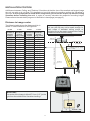
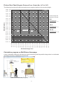
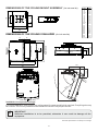
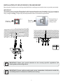
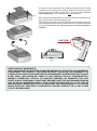
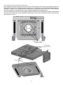
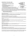
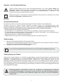
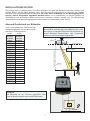
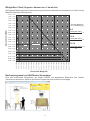
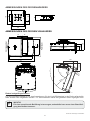
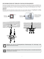
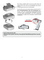
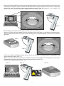
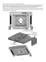
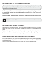
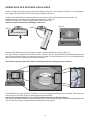
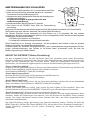
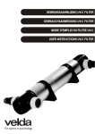
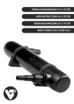
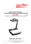
R
INSTALLATION MANUAL
MONTAGEANLEITUNG
VZ-C12³ / VZ-C32³
ENGLISH / DEUTSCH
Check out our Internet Homepage for additional information
www.wolfvision.com/support
ENGLISH
Precautions
WARNING!
Risk of electric shock
Dangerous voltage inside
Please observe the following:
CAUTION! INSTALLATION AND SERVICING OF THE VISUALIZER MUST BE PERFORMED BY
QUALIFIED SERVICE/INSTALLATION PERSONNEL FOLLOWING THE MANUFACTURER'S
INSTALLATION INSTRUCTIONS AND IN COMPLIANCE WITH THE NATIONAL ELECTRIC CODE,
ALL LOCAL BUILDING AND SAFETY CODES AND ALL OTHER APPLICABLE CODE PROVISIONS
OR REGULATIONS.
PINCH POINT! MOVING FOLDING MECHANISM CAN CRUSH FINGERS.
KEEP HANDS CLEAR. LOCKOUT BEFORE SERVICING.
USE THIS UNIT ONLY WITH THE CORRECT VOLTAGE AS SHOWN ON THE TYPE LABEL !
DO NOT EXPOSE THE UNIT TO HEAT OR MOISTURE !
PROTECT THE UNIT FROM EXCESSIVE SHOCKS !
Make sure that sufficient air circulation for cooling the unit is possible (around the unit)!
If there is any abnormality (abnormal noise, smell, smoke etc.) disconnect the unit from mains
immediately and contact your Visualizer dealer!
Do not use a damaged power cord. This may cause short circuits or electrical shocks!
To prevent danger, do not modify the unit or operate without the cover panel firmly in place!
Do not expose the unit to water, metallic objects or any flammable material.
Avoid installing the unit in locations exposed to strong magnetic fields or electrical currents.
Avoid installing the unit in environments where there is radiation. This could cause monitor image
distortion or damage to the CCD camera.
Do not pull the plug from the power socket with wet hands!
If the unit is not used for a long time, disconnect it from mains!
Precautions for laser pointer:
Laser light - Do not stare into beam!
Do not modify the laser!
Do not view the laser beam with optical instruments!
Information for laser pointer
FDA accession number: 9912688-00
This device complies with 21 CFR 1040.10 and 1040.11
CAUTION!
Pinch Point!
Technical data:
λ = 635 - 680nm
P < 1mW
Θ 2mrad
This label will be found on the
underneath of the remote
control.
The laser beam exits the
remote control through the
smaller (left) opening on
the front.
1
security lock
mechanism
Approval
Marks on the unit:
Tested to complywith
FCC standards for
home or office use
FCC information:
This device complies with part 15 of the FCC rules. Operation is subject to the following two conditions: (1)
this device may not cause harmful interference, and (2) this device must accept any interference received,
including interference that may cause undesired operation.
Note:
This equipment has been tested and found to comply with the limits for a class B digital device, pursuant to
part 15 of the FCC rules.
Information to user:
The user manual or instruction manual for an intentional or unintentional radiator shall caution the user that
changes or modifications not expressly approved by the party responsible for compliance could void the
user's authority to operate the equipment.
This product is built according to Directive EMC and to Directive electrical equipment.
Inspections, tests and evaluation are according to UL 60950. CSA 22.22-60950
Inspections, tests and evaluation are according to the CB-Scheme
Inspections, tests and evaluation are according to the PCT-Scheme
Worldwide Patents
EU 0 362 737
DE P58907684.1-08
CN 89107780.4
JP 1725033
KR 128059
US 5,027,219
EU 0 987 874
JP 3 544 900
AU 765617
CN ZL99118847.0
and others
Copyright Information
Copyright © by WolfVision. All rights reserved.
WolfVision, Wofu Vision and
are registered trademarks of WolfVision Holding AG, Austria.
No part of this document may be copied, reproduced, or transmitted by any means, without prior written
permission from WolfVision. Except documentation kept by the purchaser for backup purposes.
In the interest of continuing product improvement, WolfVision reserves the right to change product
specifications without notice.
Information in this document may change without notice.
Disclaimer: WolfVision shall not be liable for technical or editorial errors or omissions.
The units are "MADE IN EU/AUSTRIA”
Printed in Austria, August 2014
2
Symbol Legend
Attention
This symbol marks safety instruction procedures where a High Risk of Personal Injury is
present. Be sure to read all directions very carefully and exercise extreme caution! Also be sure
to follow proper health and safety rules in accordance with applicable local and federal laws.
This symbol marks instructions that require special attention in order to avoid possible
Equipment Damage.
G
Attention
Warning
Safety Procedures
The Ceiling Visualizer is built with state-of-the-art technology and is safety engineered. Regardless of this,
operational risks may be present if proper safety procedures are not obeyed.
It is essential that all safety and instruction procedures are read and followed accordingly!
-
Store all operation manuals in an easily accessible area !
The unit must be installed or repaired by authorized and certified personnel only !
Always follow safety and operational procedures when working with the unit !
Respect all warning and operation signs !
Security features must not be disabled or removed !
Preparation
1.)
2.)
Inspect the unit for any transport damage. In the event that damage is found, call your
WolfVision dealer immediately and do not attempt installation of the Ceiling Visualizer !
Confirm that all parts and accessories are present.
G
Read through the entire Installation Manual before beginning with the installation !
Ceiling Preparation
Due to the diverse installation possibilities of our ceiling mounting bracket, WolfVision kindly requires you to
mount the appliance only on a concrete ceiling capable of carrying heavy load. Please study the following
installation steps carefully. Should you encounter any problems (not covered in the installation
instructions), please contact your WolfVision representative for assistance. Take special notice regarding
the weight of the Ceiling Visualizer and the potential for personal injury, as well as the possibility for damage
to the Ceiling Visualizer or other objects that may occur if proper mounting precautions are not followed !
Failure to follow instructions can lead to severe injury!
To avoid possible injury, ensure that the ceiling construction is able to support five times
the required Visualizer weight !
3
INSTALLATION POSITION
A difference between Ceiling- and "Desktop-"Visualizers is that the size of the smallest and largest image
the unit can pick up is not fixed. This depends on how high above the working surface the Visualizer is
mounted. It is very important to know which image sizes you would like to pick up with the Ceiling
Visualizer before installing the unit, in order to correctly calculate the respective mounting height.
Please refer to the calculation program on WolfVision's homepage (see page 5).
Distance to image center
The following table shows the distance which is
called "x" in the illustration on the right side:
In extremely high rooms the smallest image the
unit can pick-up may not be small enough. In
such cases a standard ceiling mount or
projector-lift can be used to suspend the Ceiling
Visualizer further from the ceiling.
in mm
in mm
in Inch
in Inch
Distance
Distance
Distance
Distance
Visualizer to VisualizerVisualizer to Visualizerworking
front to
working
front to
surface
image center
surface
image center
66
99
164
229
294
359
424
489
554
619
684
749
814
879
944
1,009
1,074
1,139
1,204
1,269
1,334
44
50
60
70
80
90
100
110
120
130
140
150
160
170
180
190
200
2.84
4.79
8.04
11.28
14.53
17.78
21.03
24.28
27.53
30.78
34.03
37.28
40.53
43.78
47.03
50.27
53.52
206 mm
8.11 inch
452 mm / 17.8 inch
Distance (refer to tables opposite)
1,100
1,200
1,400
1,600
1,800
2,000
2,200
2,400
2,600
2,800
3,000
3,200
3,400
3,600
3,800
4,000
4,200
4,400
4,600
4,800
5,000
ceiling
x
suspended ceiling
(if required)
x mm = distance * tan 18° - 291mm
x"
= distance * tan 18° - 11.45"
(tan 18° = 0.3249)
18°
Audience
IMPORTANT:
The center of the image is offset 87.5 mm (3.5 ") to the
right, from the middle of the Visualizer housing !
y
4
87,5 mm / 344"
Picture Size Chart (Regular Distance From 1.1m to 5m / 44" to 196")
The following chart shows image size (optical zoom range) in relation to the mounting height:
43.31" / 1.1m
47.24" / 1.2m
55.12" / 1.4m
62.99" / 1.6m
70.87" / 1.8m
* vertical image size
depends on format
78.74" / 2.0m
86.61" / 2.2m
4:3
94.49" / 2.4m
horizontal size
x3
4
Object distance
102.36" / 2.6m
110.24" / 2.8m
16:9
118.11" / 3.0m
horizontal size
x9
16
125.98" / 3.2m
133.86" / 3.4m
141.73" / 3.6m
Zoom range
Tele
16:10
Wide
horizontal size
x 10
16
149.61" / 3.8m
157.48" / 4.0m
165.35" / 4.2m
173.23" / 4.4m
181.10" / 4.6m
188.98" / 4.8m
86.61" / 2.20m
82.68" / 2.10m
78.74" / 2.00m
70.87" / 1.80m
66.93" / 1.70m
62.99" / 1.60m
59.06" / 1.50m
55.12" / 1.40m
51.18" / 1.30m
47.24" / 1.20m
43.31" / 1.10m
39.37" / 1.00m
35.43" / 0.90m
31.50" / 0.80m
27.56" / 0.70m
23.62" / 0.60m
19.69" / 0.50m
15.75" / 0.40m
7.87" / 0.20m
11.81" / 0.30m
3.94" / 0.10m
0.00" / 0.00m
197.85" / 5.0m
Horizontal image size *
Calculation program on WolfVision Homepage
A very comfortable method to calculate the exact positioning and the possible image sizes is a dedicated
calculation program on WolfVision's homepage:
www.wolfvision.com (Support)
5
(for inch see list)
58,1
80
70
40
135
160
DIMENSIONS OF THE CEILING VISUALIZER
18
(for inch see list)
mm
Inch
12
18
40
58,1
60
70
72
80
90
92
95
125,5
135
144
160
206
240
285
352
390
400
452
528
0.47
0.71
1.57
2.29
2.36
2.76
2.83
3.15
3.54
3.62
3.74
4.94
5.31
5.67
6.3
8.11
9.45
11.22
13.86
15.35
15.75
17.8
20.79
206
Audience
72
285
352
12
Speaker
95
125,5
80
160
60
DIMENSIONS OF THE CEILING MOUNT ASSEMBLY
29
400
240
452
144
160
0
528
°
70
R9
90
R3
Installation in suspended ceilings:
For normal operation, only a hole in the ceiling panel for camera and light is required. Everything else may
be covered. The unit only needs to be accessed in the event it may require service.
G
IMPORTANT
Sufficient ventilation is to be provided, otherwise it can result to damage of the
equipment.
Technical Specifications are Subject to Change!
6
INSTALLATION OF WOLFVISION’S CEILING MOUNT
Mounting the Visualizer on the ceiling using WolfVision's ceiling mount can be done very quickly and easily.
IMPORTANT!
The ceiling mount must be affixed directly with three steel anchors as illustrated in fig.1 to concrete to
ensure a secure mounting and operation of the Visualizer! Ensure that the ceiling construction is able to
carry a weight of 80 kg (176 pounds) and that possible collision accidents are prevented.
fig.1
Final position of
Visualizer with
ceiling mount
Direction
of the user
min. 61
Direction
of the user
concrete
min. 15
max. 17
Ø8
mm
Inch
8
15
17
61
0.315
0.59
0.67
2.4
G
IMPORTANT: Please give special attention to the country specific regulations for
training and conferencing rooms.
G
IMPORTANT: Ensure solid mounting and secure connection of all parts to avoid the
possibility that the unit detaches itself from the ceiling.
7
fig.2
In order to fix the assembly to the ceiling, please hold the Ceiling
Visualizer to the ceiling mount (fig.2), connect it and turn the unit
by 90 degrees to the left or right (fig.3). The unit is now installed
only temporarily. The installation is not finished yet!
Now, press the release button on the Visualizer to release the unit
(fig.4) and pull the unit downwards (fig.5).
The folding mechanism will be fixed with the automatic security
lock mechanism to prevent injuries because of unintentional fold
up (fig.5). Pull and turn the lock mechanism counter-clockwise to
release it.
fig.3
CAUTION!
Pinch Point!
fig.4
security lock
mechanism
fig.5
LIMITATION OF WARRANTY!
WOLFVISION MAKES NO EXPRESS OR IMPLIED WARRANTY, STATUTORY OR OTHERWISE,
CONCERNING THE PRODUCT, INCLUDING WITHOUT LIMITATION ANY WARRANTY OF
FITNESS FOR A PARTICULAR PURPOSE OR ANY WARRANTY OF MERCHANTABILITY. IN NO
EVENT SHALL WOLFVISION BE LIABLE TO ANY PERSON FOR ANY CONSEQUENTIAL,
INDIRECT EXEMPLARY, SPECIAL OR PUNITIVE DAMAGES OR DAMAGES FOR LOST
PROFITS. WOLFVISION SHALL IN NO EVENT BECOME LIABLE FOR ANY DAMAGES ARISING
OUT OF OR IN CONNECTION WITH A FAULTY INSTALLATION DUE TO (1) THE USE OF
INAPPROPRIATE MOUNTING PARTS, (2) MOUNTING THE CEILING MOUNT TO A CEILING
WHICH DOES NOT PROVIDED A SUFFICIENTLY SECURE SUPPORT OR (3) ANY OTHER
FAULTY WORKMANSHIP.
8
Mount the stabilization ring with the enclosed Allen screws loosely into the corresponding screw threads
(fig.6). Don’t tighten the Allen screws yet.
Now move the Ceiling Visualizer into unreleased position (fig.7). Pull and turn the security lock mechanism
counter-clockwise to release it.
fig.6
security lock
mechanism
fig.7
Move the Visualizer into the desired position (fig.8). Once the position has been found, release the
Visualizer (fig.9) and tighten the Allen screws to prevent the unit from detaching and moving (fig.10).
fig.8
fig.10
fig.9
All required cables can now be pulled through the opening of the ceiling mount and connected (fig.11).
Move the Visualizer back into the unreleased position (fig.12). Pull and turn the security lock mechanism
counter-clockwise to release it.
Make sure that the folding mechanism is completely closed. You will hear a "click" sound when it is
completely closed. (fig.13).
fig.11
fig.12
fig.13
security lock
mechanism
9
The Visualizer can be readjusted if necessary.
By loosening both Allen screws the unit can be turned by 45 degrees to the left or right (please make sure
that both Allen screws are retightened after readjustment). The Visualizer can also be moved backwards or
forwards +/- 30mm (1.18") by loosening the three mounting plate hex nuts on the steel anchors (please
make sure that the mounting plate hex nuts are retightened again after readjustment).
Also, the Visualizer can be moved to the right or left by loosening the six clamping nuts (again, please make
sure that these clamping nuts are retightened afterwards). Two of the six clamping nuts are accessible by
releasing the unit only.
+/- 45°
+/- 30 mm
+/- 30 mm
stabilization ring with
2 Allen screws
3 mounting
plate hex nuts
6 clamping nuts
10
INSTALLATION OF AN EXTERNAL CEILING MOUNT
If the Visualizer needs to be suspended further from the ceiling than with the supplied ceiling mount (in
order to allow greater magnification), a standard ceiling mount or ceiling lift for projectors may be used.
An adapter plate, suitable for weight and screw fittings for the Visualizer, might be necessary.
Fixing the assembly to the ceiling is dependant on the respective construction and desired mounting
location. Ensure that the ceiling construction is able to carry a weight of 80kg (176 pounds) and that
possible collision accidents are prevented.
Important: Please give special attention to the country specific regulations for training and
conferencing rooms! Please give special attention to the country specific regulations for training
and conferencing rooms!
G
IMPORTANT: Ensure solid mounting and secure connection of all parts to avoid the
possibility that the unit detaches itself from the ceiling.
INSTALLATION OF THE VISUALIZER IN A PLENUM BOX
The Ceiling Visualizer can also be installed in a Plenum box which allows the unit to be turned by +/- 45
degrees. To do this, the mounting plate must be installed in the Plenum box in a centred position.
A non-centred position could later prevent the Visualizer from turning or releasing. A Plenum box doesn’t
allow a horizontal or vertical movement of the Visualizer. Please follow the instructions outlined on pages
4ff to install the Visualizer in a Plenum box.
INSTALLATION IN A SUSPENDED CEILING OR PLENUM BOX
When the unit is built-in into the ceiling or plenum box, the infrared receivers on the sides are covered. If the
infrared receiver beside the main switch is covered or insufficient, the supplied external infrared receiver
should be connected to the "IR-SENSOR" port.
Alternatively, the unit can be controlled with the RS-232, LAN or USB-port.
11
DISMANTLING OF THE CEILING VISUALIZER
Should it be required to dismantle the Ceiling Visualizer due to relocation or after sales service, please
follow the instructions outlined below.
Turn off the unit at the main switch and press the release button (fig.14).
Release the Visualizer to the opened holding position (fig.15).
Unplug all connected cables and remove them from the ceiling mount (fig.16).
Remove all cables completely from the ceiling mount.
Remove the ceiling mount once all cables are completely removed.
fig.14
fig.16
fig.15
Remove both Allen screws and stabilization ring (fig.17)
Press the safety lever to the top by using a normal slot screw driver (fig.18) and turn the lever to the centre
position by 60 degrees (the lever must click in pulled position).
The Ceiling Visualizer can not be removed without following this process.
fig.17
fig.18
Subsequently, the Visualizer must be moved back towards the ceiling and locked in place. The Visualizer
can now be removed by turning it by 90 degrees. Please take into consideration the weight of the unit
(13 kilos / 29 pounds) when detaching it from the ceiling. The safety lever will automatically reactivate
with the next installation and will secure the Visualizer from detaching itself.
12
OPERATION OF THE VISUALIZER
#24
1. Connect the cable to the unit (#11) and the network
(all cables can be hidden by pulling them through
the ceiling mount).
2. If you wish to connect a control monitor, please use
the Preview RGBHV Output (#16)
3. Connect the primary monitor or video projector to
the output of the Visualizer.
#21
To select the proper output, please read the user manual!
4. Turn the main switch on the unit (#8) to “I” (Power LED must illuminate)
5. Turn on the unit using the POWER button (#39) on the remote control.
#37
#39
When the Visualizer is switched on the first time, the Quick Setup Guide will be started automatically (onscreen menu). The settings are: Language, Ethernet Settings, Time Settings and the Height Adjustment.
The Ceiling Visualizer is pre-set to a distance of 2 m (78.76"). In most installations the installation height will
be different to this, so the following adjustments must be performed:
1. Adjustment of camera and light focus
2. Alignment of lightfield and camera field
It is only necessary to conduct the setting procedure once, unless the distance between the Visualizer and
working surface is changed.
Additionally the Visualizer offers the possibility to assign up to three different Height Adjustment settings to
the presets in the on-screen menu. Please read the user manual for more details.
HEIGHT ADJUSTMENT (using On-Screen Menu)
On the display screen, the On-Screen Menu of the Visualizer appears (first time the unit is turned on).
WolfVision recommends to use the function “Auto Height Adjustment” and follow the instructions shown on
the screen. Should the unit be unable to adjust itself (e.g. bright ambient light), please adjust the height
manually:
“Step 1: Center the Lightfield”
Center the lightfield until it is roughly in the center of the camera picture. Use the arrow buttons (MEMORY
2/4/6/8) (#24) to center the lightfield. Confirm the setting by pressing the MEMORY 5 key (#37).
“Step 2: Adjust Camera Focus”
Use the FOCUS button (#29) until a sharp image is visible. Confirm the setting by pressing the MEMORY 5
key (#37).
“Step 3: Adjust Light Focus”
With the FOCUS key (#29), you can focus the edge of the lightfield that is visible on the working surface until
it is sharp. Again, confirm the setting by pressing the MEMORY 5 key (#37).
“Step 4: Center light field”
With the arrow buttons (Memory 2/4/6/8) you can center the lightfield with the picture. When the lightfield is
centered, press the MEMORY 5 key (#37) to complete the setting procedure and exit the Height Adjustment
mode.
“Step 5: Accept result?” (automatic adjustment only)
Once the settings are correct, confirm the settings to complete the Height Adjustment Function. If the
settings are incorrect, press the MENU button to exit the adjustment mode. The Height Adjustment Menu
starts automatically when the unit is turned back on again until all settings are confirmed (mains switch).
The Height Adjustment procedure can be repeated at any time. Just press the MENU button (#21) to open
the on-screen menu. Select Advanced Settings / Height Adjustment with the arrow keys (MEMORY 2/8,
4/6), enter the Height Adjustment. Then select “Start Height Adjustment” to repeat the above steps.
13
DEUTSCH
Vorsichtsmaßnahmen
WARNUNG!
Elektroschockrisiko
gefährliche Spannungen
im Geräteinneren
Angeführte Vorsichtsmaßnahmen unbedingt beachten:
DAS GERÄT DARF NUR VON AUTORISIERTEN UND GESCHULTEN FACHKRÄFTEN MONTIERT UND
GEWARTET WERDEN.
QUETSCHGEFAHR! SCHWENKEINHEIT KANN FINGER QUETSCHEN. NICHT IN DEN SCHWENKMECHANISMUS GREIFEN. VOR SERVICEARBEITEN SICHERHEITSVERRIEGELUNGSMECHANISMUS KONTROLLIEREN.
DAS GERÄT NUR MIT DER AUF DEM TYPENSCHILD ANGEGEBENEN SPANNUNG BETREIBEN !
DAS GERÄT VOR HITZE UND FEUCHTIGKEIT SCHÜTZEN !
DAS GERÄT VOR ERSCHÜTTERUNG SCHÜTZEN !
Darauf achten, dass eine ausreichende Luftzirkulation zur Kühlung des Gerätes möglich ist
(gesamtes Gerät)!
Bei jeder Art von Störungsanzeichen (abnormale Geräusche, Geruch, Rauchentwicklung, etc.) das
Gerät abschalten. Setzen Sie sich bitte in solchen Fällen umgehend mit Ihrem Visualizer-Händler in
Verbindung!
Niemals ein beschädigtes Netzkabel verwenden. Andernfalls kann es zu Kurzschlüssen und zu
elektrischen Schlägen kommen!
Am Gerät keinerlei Umbauten vornehmen und das Gerät niemals ohne Gehäuse-deckel in Betrieb
nehmen!
Keine entflammbaren oder metallischen Gegenstände oder Flüssigkeiten in das Geräteinnere
dringen lassen!
Das Gerät nicht im Bereich von starken Magnetfeldern und elektrischen Feldern in Betrieb nehmen!
Das Gerät nicht im Wirkungsbereich von Röntgenstrahlung betreiben. Dadurch können Teile der
Kamera beschädigt werden.
Das Netzkabel und den Netzstecker niemals mit feuchten Händen berühren!
Das Gerät bei längerer Nichtbenutzung vom Netz trennen (Hauptschalter)!
Vorsichtsmaßnahmen für den Laserpointer
Laserstrahlen - Nicht direkt den Laserstrahl blicken!
Laser nicht modifizieren! Laserstrahl nicht mit
optischen Instrumenten betrachten!
Information für den Laserpointer
FDA Zugriffsnummer: 9912688-00
Entspricht den Vorschriften: 21 CFR 1040.10 und 1040.11
ACHTUNG!
Quetsch
Gefahr!
Technische Daten:
λ = 635 - 680nm
P < 1mW
Θ 2mrad
Dieser Aufkleber befindet sich
auf der Unterseite der
Fernbedienung.
Die kleinere Öffnung
(links) an der Frontseite
der Fernbedienung ist die
Laserstrahl-Austrittsöffnung.
1
Sicherheitsveriegelungsmechanismus
Prüfungen
Aufkleber am Gerät:
Tested to complywith
FCC standards for
home or office use
FCC information (original Text):
This device complies with part 15 of the FCC rules. Operation is subject to the following two conditions: (1)
This device may not cause harmful interference, and (2) this device must accept any interference received,
including interference that may cause undesired operation.
Note:
This equipment has been tested and found to comply with the limits for a class B digital device, pursuant to
part 15 of the FCC rules.
Information to user:
The user manual or instruction manual for an intentional or unintentional radiator shall caution the user that
changes or modifications not expressly approved by the party responsible for compliance could void the
user's authority to operate the equipment.
Dieses Gerät entspricht der EMC-Verordnung und der Verordnung für elektrische Geräte.
Prüfungen, Tests und Untersuchungen wurden nach UL 60950. CSA 22.22-60950 durchgeführt.
Prüfungen, Tests und Untersuchungen wurden nach dem CB-Schema durchgeführt.
Prüfungen, Tests und Untersuchungen wurden nach dem PCT-Schema durchgeführt.
Weltweite Patente
EU 0 362 737
DE P58907684.1-08
CN 89107780.4
JP 1725033
KR 128059
US 5,027,219
EU 0 987 874
JP 3 544 900
AU 765617
CN ZL99118847.0
und weitere
Copyright Information
Copyright © WolfVision. Alle Rechte vorbehalten.
WolfVision, Wofu Vision und
Austria.
sind registrierte Warenzeichen der WolfVision Holding AG,
Dieses Dokument darf ohne vorherige schriftliche Zustimmung von WolfVision weder als Ganzes noch in
Teilen mit irgendwelchen Mitteln kopiert, reproduziert oder übertragen werden. Ausgenommen sind
Kopien, die vom Benutzer zu Sicherungszwecken aufbewahrt werden.
Im Interesse einer ständigen Produktverbesserung behält sich WolfVision das Recht vor, die
Produktspezifikationen ohne Ankündigung zu ändern.
Änderungen an diesem Dokument bleiben vorbehalten.
Haftungsausschlusserklärung: WolfVision ist nicht haftbar für technische und redaktionelle Fehler und
Unvollständigkeit.
Die Geräte sind "MADE IN EU/AUSTRIA”
Gedruckt in Österreich, August 2014
2
Symbol- und Hinweiserklärung
Vorsicht
G
Dieses Symbol finden Sie bei allen Sicherheitshinweisen, bei denen große Gefahr für
Personen besteht. Beachten Sie diese Hinweise und verhalten Sie sich sehr vorsichtig!
Außerdem müssen die geltenden Gesetze und allgemeingültigen Sicherheits- und
Unfallverhütungsvorschriften beachtet werden.
Steht bei Hinweisen, Vorschriften und Arbeitsabläufen, die besonders zu beachten sind, damit
Sachbeschädigungen verhindert werden.
Achtung
Warnung
Sicherheitshinweise
Der Decken Visualizer ist nach dem aktuellsten Stand der Technik gebaut und betriebssicher.
Trotzdem können von diesen Geräten Gefahren ausgehen, wenn sie unsachgemäß oder nicht
bestimmungsgemäß eingesetzt werden. Daher sollten Sie unbedingt die Betriebsanleitung des
Gerätes, sowie die darin enthaltenen Sicherheitshinweise lesen und genau beachten!
- Die Betriebsanleitung zugänglich aufbewahren!
- Das Gerät darf nur von autorisierten und geschulten Fachkräften montiert oder repariert werden!
- Für den Betrieb des Gerätes gelten in jedem Fall die örtlichen Sicherheits- und Unfallverhütungsvorschriften. Diese sind zu beachten und einzuhalten!
- Angebrachte Hinweis- und Warnschilder beachten!
- Sicherheitseinrichtungen dürfen nicht außer Betrieb gesetzt oder entfernt werden!
Vorbereitung
1.)
2.)
.
Überprüfen Sie das Gerät bitte auf Transportschäden!
Sollte es zu einer Beschädigung gekommen sein, kontaktieren Sie Ihren Händler für weitere Schritte.
Stoppen Sie in diesem Fall die Installation des Visualizers!
Überprüfen Sie alle Teile auf Ihre Vollständigkeit.
G
Lesen Sie die Installationshinweise durch, bevor Sie mit der Installation beginnen!
Vorbereitung der Decke
Aufgrund der breiten Palette von Installationsmöglichkeiten unseres Deckenhängers schreibt die Firma
WolfVision vor die Montage nur an einer tragfähigen Betondecke durchzuführen. Lesen Sie bitte die
folgenden Installationsschritte gründlich durch. Sollten Sie eine spezielle (nicht in der
Installationsanleitung angeführte) Lösung benötigen, bitten wir Sie um Abklärung mit unseren Händlern.
Berücksichtigen Sie das Gewicht des Decken Visualizers und das Potential für Personenschäden, aber
auch die Möglichkeit von einer Beschädigung des Decken Visualizers und Einrichtungsgegenständen bei
unsachgemäßer Montage!
Unsachgemäße Installation kann zu schweren Verletzungen führen!
Um solche Verletzungen zu verhindern, stellen Sie sicher, dass die Deckenkonstruktion
mindestens das Fünffache des Gewichtes tragen kann, das sie nach der Installation
halten muss!
3
INSTALLATIONSPOSITION
Ein Unterschied zu herkömmlichen Visualizer Modellen ist, dass die Abmessungen des kleinsten und
größten Bildes, die das Gerät abtasten kann, nicht fix sind. Es hängt davon ab, wie hoch der Decken
Visualizer über der Arbeitsfläche montiert wird. Es muss daher unbedingt vor der Montage abgeklärt
werden, welche Bildgrößen abgetastet werden sollen, um zu entscheiden, in welcher Distanz zur
Arbeitsfläche und auf welche Weise der Decken Visualizer montiert werden soll. Zur Berechnung
verwenden Sie bitte das Rechenprogramm auf der WolfVsion Homepage (siehe Seite 5).
Abstand Gerätefront zur Bildmitte:
in mm
Abstand
Visualizer
zur Arbeitsfläche
in mm
Abstand
VisualizerFront zur
Bildmitte
1,100
1,200
1,400
1,600
1,800
2,000
2,200
2,400
2,600
2,800
3,000
3,200
3,400
3,600
3,800
4,000
4,200
4,400
4,600
4,800
5,000
66
99
164
229
294
359
424
489
554
619
684
749
814
879
944
1,009
1,074
1,139
1,204
1,269
1,334
In extrem hohen Räumen ist möglicherweise das
kleinste Bild, welches das Gerät abtasten kann, nicht
klein genug. In solchen Fällen kann der Visualizer mit
einem Standard Deckenhänger oder Projektorlift
weiter von der Decke abgehängt werden.
Decke
206 mm
452 mm
x
Abgehängte Decke
(sofern erwünscht)
x mm = Abstand * tan 18° - 291mm
(tan 18° = 0,3249)
Abstand (siehe Tabelle nebenan)
In der unten stehenden Tabelle wird der
Abstand angegeben, der auf der Graphik
rechts als "x" bezeichnet ist:
18°
Publikum
WICHTIG:
Die Bildmitte ist um 87,5mm gegenüber dem
Zentrum des Visualizers nach rechts verschoben!
y
4
87,5 mm
Bildgrößen Chart (Regulärer Abstand von 1.1m bis 5m)
Die folgende Tabelle zeigt den Zusammenhang zwischen dem Abstand des Visualizers zum Tisch und der
Bildgröße (optischer Zoombereich):
43.31" / 1.1m
47.24" / 1.2m
55.12" / 1.4m
62.99" / 1.6m
70.87" / 1.8m
* Vertikale Bildgröße
ist Formatabhängig
78.74" / 2.0m
Abstand zum Objekt
86.61" / 2.2m
4:3
94.49" / 2.4m
Horizontale Größe
x3
4
102.36" / 2.6m
110.24" / 2.8m
16:9
118.11" / 3.0m
Horizontale Größe
x9
16
125.98" / 3.2m
133.86" / 3.4m
141.73" / 3.6m
Zoom range
Tele
16:10
Wide
Horizontale Größe
x 10
16
149.61" / 3.8m
157.48" / 4.0m
165.35" / 4.2m
173.23" / 4.4m
181.10" / 4.6m
188.98" / 4.8m
86.61" / 2.20m
82.68" / 2.10m
78.74" / 2.00m
70.87" / 1.80m
66.93" / 1.70m
62.99" / 1.60m
59.06" / 1.50m
55.12" / 1.40m
51.18" / 1.30m
47.24" / 1.20m
43.31" / 1.10m
39.37" / 1.00m
35.43" / 0.90m
31.50" / 0.80m
27.56" / 0.70m
23.62" / 0.60m
19.69" / 0.50m
15.75" / 0.40m
7.87" / 0.20m
11.81" / 0.30m
3.94" / 0.10m
0.00" / 0.00m
197.85" / 5.0m
Horizontale Bildgröße
Rechenprogramm auf WolfVision Homepage
Eine sehr komfortable Möglichkeit, die exakte Position und abtastbaren Bildgrößen des Decken
Visualizers zu berechnen, bietet ein spezielles Programm auf der WolfVison Homepage:
www.wolfvision.com (Support)
5
58,1
80
70
40
80
160
60
ABMESSUNGEN DES DECKENHÄNGERS
135
160
ABMESSUNGEN DES DECKEN VISUALIZERS
18
72
125,5
206
Publikum
285
352
12
Vortragender
95
29
400
240
452
144
160
0
528
°
70
R9
90
R3
Einbau in abgehängte Decken:
Für den normalen Betrieb ist nur eine Ausnehmung für den Licht-/Bildauslass in der Decke erforderlich.
Alles andere kann abgedeckt werden. Für Servicezwecke sollte das gesamte Gerät zugänglich sein.
G
WICHTIG
Für eine ausreichende Belüftung ist zu sorgen, andernfalls kann es zu einer Beschädigung des Gerätes kommen.
Technische Änderungen vorbehalten!
6
DECKENMONTAGE MIT DEM WOLFVISION-DECKENHÄNGER
Der Decken Visualizer lässt sich sehr schnell und komfortabel mit dem Deckenhänger von WolfVision an
der Decke befestigen. Die Fixierung an der Decke erfolgt durch die Anbringung des Deckenhängers an
eine Betondecke. Montieren Sie den Deckenhänger an der Decke mit drei Stahlankern wie in Abb. 1
abgebildet.
WICHTIG!
Die Decke, an der der Visualizer montiert werden soll, muss in jedem Fall für eine Tragfähigkeit von 80kg
ausgelegt sein um mögliches Herunterstürzen durch Kollision auszuschließen.
Abb.1
Decken Visualizer
mit Deckenhänger
in Endposition
Richtung
Anwender
min. 61
Richtung
Anwender
Beton
min. 15
max. 17
Ø8
G
WICHTIG: Es sind die länderspezifischen Bestimmungen für Schulungs- und
Konferenzräume zu beachten.
G
WICHTIG: Auf sichere Befestigung und Verschraubung achten, um das Herunterstürzen
des Gerätes zu verhindern!
7
Abb.2
Der Decken Visualizer kann nun wie im Bild zuerst zum
Deckenhänger geführt (Abb. 2) und anschließend mit einer 90°
Drehung nach rechts oder links provisorisch fixiert werden.
(Abb. 3)
Die Montage ist hiermit noch nicht beendet!
Der Visualizer kann nun mit einem leichten Knopfdruck (Abb. 4)
gelöst und anschließend nach unten geklappt werden (Abb. 5).
Der Schwenkmechanismus wird, um Verletzungen vorzubeugen, durch den Sicherheitsverriegelungsmechanismus
automatisch gegen unbeabsichtigtes Hochklappen ge-sichert.
Um das Gerät Hochzuklappen, muss die Verriegelung
rausgezogen und gegen den Uhrzeigersinn gedreht werden
(siehe Abb. 5).
Abb.3
ACHTUNG!
Quetschgefahr!
Abb.4
Sicherheitsverriegelungsmechanismus
Abb.5
HAFTUNGSAUSSCHLUSS!
WolfVision übernimmt keine Haftung, wenn minderwertiges Material verwendet, eine nicht
tragfähige Decke gewählt oder bei der Montage der Deckenbefestigung Fehler gemacht
werden!
8
Montieren Sie den Stabilisierungsring mit den beiliegenden Inbus-Sicherungsschrauben locker in die dafür
vorgesehenen Gewinde. (Abb. 6) Ziehen Sie die Inbus-Sicherungsschrauben noch nicht fest. Ziehen und
drehen Sie den Sicherheitsverriegelungsmechanismus gegen den Uhrzeigersinn und klappen Sie
anschließend den Decken Visualizer in die geschlossene Stellung. (Abb. 7)
Abb.6
Sicherheitsverriegelungsmechanismus
Abb.7
Richten Sie den Visualizer auf die gewünschte Position aus. (Abb. 8)
Wenn die Position stimmt, klappen Sie den Visualizer nach unten (Abb. 9) und fixieren Sie beide InbusSicherungsschrauben (Abb.10). Damit ist das Gerät gegen ein selbstständiges Lösen oder Verrutschen
gesichert.
Abb.8
Abb.10
Abb.9
Alle für den Betrieb benötigten Kabel können durch die Öffnung im Deckenhänger durchgezogen und
angeschlossen werden. (Abb. 11)
Ziehen und drehen Sie den Sicherheitsverriegelungsmechanismus gegen den Uhrzeigersinn und drücken
Sie dann den Visualizer nach oben in die geschlossene Stellung (Abb. 12).
Der Visualizer rastet hörbar ein (Abb. 13).
Abb.11
Abb.12
Abb.13
Sicherheitsverriegelungsmechanismus
9
Der Visualizer kann, wenn nötig, noch feinjustiert werden.
Durch Lockern beider Inbus-Sicherungsschrauben kann der Visualizer um 45° nach rechts oder links
geschwenkt werden. (beide Inbus-Sicherungsschrauben müssen anschließend wieder fixiert werden).
Durch Lockern der drei Befestigungsmuttern an den Stahlankern zur Decke kann der Visualizer um +/30mm vor- oder zurückgesetzt werden (Befestigungsmuttern anschließend wieder fixieren).
Ebenfalls kann der Visualizer durch Lockern der 6 Klemmmuttern +/-30mm nach links oder rechts versetzt
werden (alle Klemmmuttern anschließend wieder fixieren). Zwei der 6 Klemmmuttern sind nur bei nach
unten geklapptem Gerät zugänglich.
+/- 45°
+/- 30 mm
+/- 30 mm
Stabilisierungsring mit
Inbus-Sicherungsschrauben
3 Befestigungsmuttern an
den Stahlankern
zur Decke
6 Klemmmuttern
10
DECKENMONTAGE MIT EXTERNEM DECKENHÄNGER
Wenn der Visualizer weiter von der Decke abgehängt werden soll (um größere Vergrößerungen zu
erhalten), kann auch ein Standard-Deckenhänger oder ein Deckenlift für Projektoren verwendet
werden. Sie benötigen ggf. aber eine Adapterplatte, welche für das Gewicht und die Verschraubung
des Decken Visualizers ausgelegt ist.
Die Fixierung an der Betondecke erfolgt durch die Anbringung des externen Deckenhängers und ist von
den jeweiligen örtlichen Gegebenheiten abhängig. Sie muss in jedem Fall für eine Tragfähigkeit von 80
kg zuzüglich des Gewichts des externen Deckenhängers ausgelegt sein um Unfälle durch Kollision
auszuschließen!
Außerdem sind die länderspezifischen Bestimmungen für Schulungs- und Konferenzräume zu
beachten!
G
WICHTIG: Auf sichere Befestigung und Verschraubung achten, um das Herunterstürzen
des Gerätes zu verhindern!
DECKENMONTAGE IN EINER PLENUM-BOX
Der Decken Visualizer wurde so konzipiert, dass er auch in einer Plenum-Box montiert und +/- 45° gedreht
werden kann. Dazu muss der Deckenhänger unverändert und zentriert in der Plenum-Box montiert
werden.
Bei einer nicht zentrierten Montage kann der Visualizer möglicherweise später nicht mehr gedreht oder
geöffnet werden. Ein horizontales oder vertikales Verschieben in der Plenum-Box ist nicht möglich. Den
Visualizer wie auf den Seiten 4ff in dieser Montageanleitung beschrieben in der Plenum-Box montieren.
EINBAU IN ABGEHÄNGTE DECKEN ODER EINER PLENUM BOX
Beim Einbau in eine Decke oder Plenum Box werden die beiden seitlichen Infrarot-Empfänger abgedeckt.
Sollte der Infrarot-Empfänger neben dem Hauptschalter auch abgedeckt sein beziehungsweise nicht
ausreichen, sollte der mitgelieferte externe Infrarot-Empfänger an die Buchse "IR-SENSOR"
angeschlossen werden.
Alternativ kann das Gerät auch über den RS232, LAN oder USB-Anschluss gesteuert werden.
11
DEMONTAGE DES DECEKEN VISUALIZERS
Sollte es aufgrund eines Umzugs oder Servicefalles nötig sein, den Decken Visualizer zu demontieren,
dann gehen Sie bitte Schritt für Schritt folgende Anleitung durch:
Schalten Sie das Gerät am Hauptschalter aus und drücken Sie den Entriegelungsknopf. (Abb. 14)
Klappen Sie den Visualizer in die geöffnete Halteposition. (Abb. 15)
Entfernen Sie alle am Visualizer angesteckten Kabel. (Abb. 16)
Kabel komplett aus dem Deckenhänger entfernen!
Abb.14
Abb.16
Abb.15
Entfernen Sie beide Inbus-Sicherungsschrauben und den Stabilisierungsring. (Abb. 17)
Um den Decken Visualizer herunterzunehmen, müssen Sie mit einem kleinen Schlitzschraubendreher
den Sicherungshebel (Abb.18) zuerst nach oben drücken und anschließen um 60° auf die Mittelposition
drehen. (Hebel muss in gespannter Position einrasten.)
Ohne diesen Vorgang kann der Decken Visualizer nicht heruntergenommen werden.
Abb.17
Abb.18
Anschließend muss der Decken Visualizer nach oben geklappt werden bis er einrastet. Jetzt kann der
Visualizer durch eine 90° Drehung heruntergenommen werden.
Achten Sie auf das Gewicht von ca. 13kg beim Herunternehmen des Visualizers.
Der Sicherungshebel wird beim nächsten Einführen auf den Deckenhänger wieder selbstständig aktiviert
und schützt so vor einem möglichen Herunterfallen des Visualizers.
12
INBETRIEBNAHME DES VISUALIZERS
1. Netzkabel am Gerät anstecken (#111) und am Netz anschließen.
2. Wenn ein Kontrollmonitor verwendet werden soll, verwenden
Sie bitte den Preview RGB Ausgang (#16)
3. Hauptmonitor oder Videoprojektor an einem der Ausgänge des
Visualizers anschließen.
Zur Wahl des richtigen Ausganges lesen Sie bitte
die Bedienungsanleitung!
4. Hauptnetzschalter (#8) am Gerät auf "I" schalten.
5. Das Gerät mit der POWER Taste (#39) der Fernbedienung
einschalten.
#24
#37
#21
#39
Beim ersten Einschalten des Visualizers startet der Quick Setup Guide automatisch (On-Screen Menü).
Die Einstellungen sind: Sprache, Netzwerk, Zeit und die Höhen Einstellung.
Der Decken Visualizer wurde werksseitig auf eine Distanz von 2 m eingestellt. Bei den meisten
Installationen differiert die Montagehöhe jedoch von der voreingestellten Höhe, deshalb müssen folgende
Einstellungen vorgenommen werden:
1. Einstellung von Kamera- und Lichtfokus
2. Justage der Lichtfeldzentrierung auf das Kamerafeld
Diese Einstellung ist nur einmalig vorzunehmen - bei der Installation des Gerätes, außer der Abstand
zwischen Visualizer und Arbeitsfläche wird verändert.
Zusätzlich bietet der Visualizer die Möglichkeit bis zu drei unterschiedliche Height Adjustment Einstellungen (Höheneinstellungen) den Presets im On-Screen Menü zuzuweisen, lesen Sie bitte die
Bedienungsanleitung für nähere Details.
HEIGHT ADJUSTMENT (Höhen-Einstellung)
Auf dem Ausgabebild sehen Sie das On-Screen Menü des Visualizers (beim ersten Einschalten).
WolfVision empfiehlt die Verwendung der Funktion "Auto Height Adjustment" (automatische Einstellung).
Folgen Sie den Anweisungen des On-Screen Menüs. Sollte die automatische Einstellung nicht
funktionieren, z.B. bei starkem Umgebungslicht, so nehmen Sie die Einstellung wie folgt manuell vor:
“Step 1: Center the Lightfield”
Zentrieren Sie hier das Lichtfeld bis es im Zentrum des Kamerabildes ist (Grobeinstellung). Benützen Sie
die Pfeil-Tasten (MEMORY 2/4/6/8) (#24) um das Lichtfeld zu zentrieren.
Anschließend mit MEMORY 5-Taste (#37) bestätigen.
“Step 2: Adjust Camera Focus”
Benützen Sie die FOCUS Tasten (#29) und stellen Sie das Bild scharf ein.
Anschließend mit MEMORY 5 Taste (#37) bestätigen.
“Step 3: Adjust Light Focus”
Mit den FOCUS-Tasten (#29) können Sie den Rand des Lichtfeldes, welches Sie auf der Arbeitsplatte
sehen, scharfstellen. Anschließend mit MEMORY 5 Taste (#37) bestätigen.
“Step 4: Center light field”
Mit den Pfeil-Tasten (Memory 2/4/6/8) (#24) können Sie das Lichtfeld im Bild zentrieren. Wenn das
Lichtfeld zentriert ist, drücken Sie die MEMORY 5 Taste (#37) um die Einstellungen zu übernehmen.
“Step 5: Accept result?” (Rückfrage nur beim automatischer Einstellung)
Wenn die Einstellungen stimmen, können Sie die Werte speichern und das Height Adjustment Menu
verlassen. Sollten die Einstellungen nicht stimmen, kann die Eingabe mit der MENU Taste verlassen
werden. Das Height Adjustment erscheint beim nächsten Mal, wenn das Gerät eingeschaltet wird,
automatisch (Hauptschalter).
Die Höhen-Einstellung (Height Adjustment) kann jederzeit wiederholt werden. Drücken Sie dafür die
MENU Taste (#21). Mit den Pfeil-Tasten (MEMORY 2/8, 4/6) den Menü Punkt „Erweiterte Einstellungen” /
„Höhen Einstellung” auswählen und die „Höhen Einstellung” starten um die obigen Schritte zu
wiederholen.
13
R
CONTACTS
Manufacturer / Worldwide Distribution
WolfVision GmbH
A-6833 Klaus
Tel: +43(5523)-52250, Fax: +43(5523)-52249
AUSTRIA
E-Mail: [email protected]
International Distribution Offices
USA
WolfVision Inc.
Duluth
(Atlanta)
Burlingame
(San Francisco)
Asia
WolfVision Pte Ltd
Singapore
Tel: +1(770)931-6802, Toll free: 877-873-WOLF, Fax: +1(770)931-6906
E-Mail: [email protected] / [email protected]
Tel: +1(650)648-0002, Toll free: 800-356-WOLF
E-Mail: [email protected] / [email protected]
Tel: +65-6636-1268, Fax: +65-6636-1269
E-mail: [email protected]
Middle East
WolfVision Middle East
Dubai
Tel: +971 (04) 354 2233, Fax: +971 (04) 354 2244
E-Mail: [email protected]
Germany
WolfVision Germany
Tel: 0800 / 98 28 787 (Toll Free for Germany)
E-mail: [email protected]
Japan
WolfVision Co. Ltd.
Tokyo
Tel: +81(0)3-6233-9465, Fax: +81(0)3-6233-9466
E-mail: [email protected]
Canada
WolfVision Canada, Inc.
Ottawa
Tel: +1(613)741-9898, Toll free: 877-513-2002, Fax: +1(613)741-3747
E-Mail: [email protected]
United Kingdom
WolfVision UK Ltd.
Maidenhead
Tel: +44 1628 509067, Fax: +44 1628 509100
E-Mail: [email protected]
Internet Homepage: www.wolfvision.com
E-Mail to technical support: [email protected]
Printed in Austria - August 2014