1
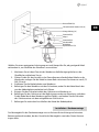
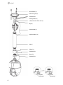
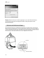
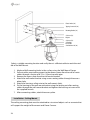
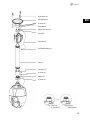
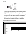
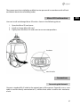
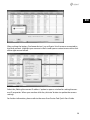
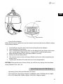
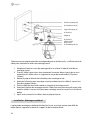
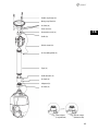
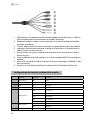
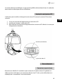
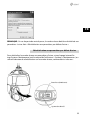
DE
EN
FR
Quick Installation Guide
1/2.8“ Network Dome, PTZ, 30x,
Day&Night, Infrared, 1920x1080
NXD-2030PTZ1080IR
Sicherheitshinweise.....................................................................................................3
Komponenten..............................................................................................................3
Installation...................................................................................................................4
Installation...................................................................................................................................................................4
Installation - Wandmontage.............................................................................................................................4
Installation - Deckenmontage.........................................................................................................................5
Grundkonfiguration des Kamerasystems.........................................................................................................7
Einfügen einer microSD-Karte..............................................................................................................................8
Anschlüsse....................................................................................................................................................................9
Anschluss an das Netzwerk...............................................................................................................................9
Anschließen von Alarmen.................................................................................................................................9
Anschluss der Stromversorgung.....................................................................................................................9
Netzwerkanschluss und IP-Zuweisung..................................................................................................... 10
Bedienung..................................................................................................................11
Zugriff über einen Browser..................................................................................................................................11
Zugriff über Internet.............................................................................................................................................. 12
Einstellung des Admin-Passworts über eine sichere Verbindung........................................................ 12
Live View-Seite........................................................................................................................................................ 13
Allgemeine Einstellelemente........................................................................................................................ 13
Steuerungs-Werkzeugleiste........................................................................................................................... 13
Video-Streams.................................................................................................................................................... 14
Wiedergabe.............................................................................................................................................................. 15
Netzwerk-Kamera-Konfiguration......................................................................................................................17
Rücksetzen auf die Werkseinstellungen................................................................................................... 18
Systemanforderungen für Webbrowser.................................................................................................... 19
Allgemeine Performance-Überlegungen................................................................................................. 19
Weitere Informationen......................................................................................................................................... 20
2
Sicherheitshinweise
Bitte beachten Sie auch die beiliegenden Sicherheitshinweise und lesen Sie diese Anleitung vor Inbetriebnahme sorgfältig durch.
Wichtige Hinweise sind mit einem Achtungsymbol gekennzeichnet.
DE
Komponenten
Das System wird mit den folgenden Komponenten geliefert:
•
•
•
•
•
•
•
Dome Kamera
Installationsanleitung/CD
RJ-45 Kupplung
2P Schraubverbinder
5P Schraubverbinder
PoE-Injektor
Adapterinstallation
3
Installation
Installation
Für die Installation benötigen Sie ein optionales Montagekit für die Wand- bzw. die
Deckenmontage.
Das Montagekit für die Wand- bzw. die Deckenmontage muss an einen festen Untergrund wie Hartholz oder Beton angebracht werden, der das Gewicht des Montagekits
sowie der Kamera tragen kann.
Bei der Anbringung an Gipswände wird die Verwendung einer festen Rückplatte
empfohlen.
1. Entfernen Sie das Schutzpolster und das Klebeband von der Dome Kamera.
2. Bringen Sie die Befestigungsplatte mit den mitgelieferten selbstschneidenden
M8-Schrauben und den Kunststoffdübeln an der Wand an. (Für die Deckenmontage die mitgelieferten selbstschneidenden M6-Schrauben und die Kunststoffdübel
verwenden.)
3. Umwickeln Sie beide Gewinde des Rohrendes zur Abdichtung etwa 20 Mal mit
Teflonband. Verwenden Sie dann ein Silikongummi-Dichtungsmittel zur Abdichtung des Bereichs, an dem sich das Wand- bzw. Decken-Montagekit und das Rohr
treffen.
4. Legen Sie einen Ring Silikon-Dichtmittel um den Flansch des Wand- bzw. DeckenMontagekits, drücken Sie letzteres auf die Oberfläche und achten Sie dabei auf
die korrekte Ausrichtung der Löcher im Montagekit in Bezug auf die Bohrlöcher.
WARNUNG 1: Es muss ein Silikon-Dichtmittel verwendet werden, um die Wasserdichtigkeit des Gehäuses sicherzustellen.
WARNUNG 2: Für die Montage ist eine Halterung zu verwenden.
Installation - Wandmontage
Das Montagekit für die Wandmontage muss auf einem festen Untergrund wie etwa Beton
angebracht werden, der das Gewicht des Montagekits sowie der Dome-Kamera tragen
kann.
4
Kunststoffdübel (4x)
DE
Selbstschneidende Schraube 8x35 (4x)
Montagehalterung (1x)
Gewindestift (1x)
Adapter
Gewindestift (1x)
Sicherheitsdraht
Abdeckplatte
Kopfschraube 3x5 (2x)
Wählen Sie einen geeigneten Anbringungsort und überprüfen Sie, ob genügend Kabel
vorhanden ist, um die Mitte des Wandarms zu erreichen.
1. Markieren Sie mit dem Flansch des Wandarms die Befestigungslöcher an der
Oberfläche und bohren Sie sie.
2. Ziehen Sie die für den Anschluss der Dome Kamera erforderlichen Kabel aus der
Wand oder verlegen Sie die Kabel in einem Rohr mit einem Durchmesser von 0,75
Zoll (19 mm).
3. Entfernen Sie die Abdeckplatte vom Wandarm.
4. Befestigen Sie den Wandarm mit den Schrauben, wobei Sie die Kabel durch das
von der Abdeckplatte verdeckte Loch führen.
5. Bringen Sie den Sicherheitsdraht des Gehäuses am Wandarm an.
6. Befestigen Sie das Gehäuse mit der Befestigungsmutter am Wandarm, nachdem
Sie die Kabel durch den Wandarm geführt haben, und ziehen Sie die Schraube
des Gehäusesatzes mit dem mitgelieferten Schlüssel an.
7. Befestigen Sie nach dem Anschließen der Kabel die Abdeckplatte.
Installation - Deckenmontage
Das Montagekit für die Deckenmontage muss auf einem festen Untergrund wie etwa
Beton angebracht werden, der das Gewicht des Montagekits sowie der Dome-Kamera
tragen kann.
5
Kunststoffdübel (3x)
Deckenmontagekit (1x)
Gewindestift (2x)
Sicherungsmutter (1x)
Selbstschneidende Schraube 6x35 (3x)
Ring (1x)
Sicherheitsdraht (1x)
Kopfschraube M5x6 (1x)
Rohr (1x)
Rohrring (1x)
Gewindestift (3x)
Adapter (1x)
Gewindestift (1x)
Startpunkt
(Langanzeige)
6
Sollwert
(Kurzanzeige)
DE
1. Wählen Sie einen geeigneten Anbringungsort und überprüfen Sie, ob genügend
Kabel vorhanden ist, um die Kabel des Gehäuses zu erreichen.
2. Markieren Sie mit dem Deckenmontageflansch die Befestigungslöcher an der
Oberfläche und bohren Sie sie.
3. Ziehen Sie die erforderlichen Kabel aus der Decke, um die Dome-Kamera
anzuschließen.
4. Befestigen Sie den Deckenmontagearm mit den Schrauben, wobei Sie die Kabel
durch die Befestigungsmutter führen.
5. Befestigen Sie das Gehäuse mit dem Ring am Rohr, nachdem die Kabel durch das
Rohr geführt wurden.
6. Bringen Sie den Sicherheitsdraht des Gehäuses an der selbstschneidenden M6x35
Schraube am Deckenmontageflansch an.
7. Befestigen Sie das Rohr nach dem Anschließen der Kabel mit der Befestigungsmutter am Deckenmontageflansch.
8. Ziehen Sie die Schrauben des Rings und die Befestigungsmutter mit dem mitgelieferten Schlüssel an.
Grundkonfiguration des Kamerasystems
Nr.
Anschluss
Farbe des Leiters
Beschreibung
1
DC-Anschluss
SCHWARZ
12 VDC
2
RJ-45
SCHWARZ
Ethernet, RJ-45 Port, kompatibel mit 10/100Mbps, (mit PoE++ Funktion)
3
RCA
SCHWARZ
Audioeingang
4
RCA
GRAU
Audioausgang
GELB
Alarmeingang 1
WEIß
Alarmeingang 2
VIOLETT
Alarmeingang 3
BRAUN
Alarmeingang 4
5
5-poliges Kabel
6
2-poliges Kabel
7
1-poliges Kabel
GRAU
GND
ROT
Alarmausgang
SCHWARZ
GND
GELB/GRÜN
F-GND
7
Die Installation der Kamera darf nur von qualifiziertem Personal in Übereinstimmung
mit den am Ort der Installation gültigen elektrischen und mechanischen Bestimmungen
erfolgen.
Einfügen einer microSD-Karte
Die Benutzer können die microSD-Karte wie in der folgenden Abbildung gezeigt einsetzen und auswechseln.
1. Öffnen Sie die Abdeckung über der microSD-Karte.
2. Fügen Sie eine microSD-Karte ein oder tauschen Sie diese aus.
3. Drücken Sie die Abdeckung der microSD-Karte fest an, um einen wasserdichten
Verschluss zu erzielen.
Reset-Taste
Schlitz für microSD-Karte
8
Anschlüsse
Anschluss an das Netzwerk
Schließen Sie ein gewöhnliches RJ-45-Kabel an den Netzwerkanschluss der Kamera an.
Zum Anschluss an einen PC wird im Allgemein ein Crossover-Kabel verwendet, während
zum Anschluss an einen Hub ein direktes Kabel (Patch-Kabel) verwendet wird.
DE
Anschließen von Alarmen
• A1,A2,A3,A4 (Alarmeingang 1,2,3,4)
Sie können externe Geräte anschließen, die der Kamera externe Ereignisse signalisieren,
damit sie auf diese reagiert. Mechanische oder elektrische Schalter können zwischen die
Anschlüsse A1,A2,A3,A4 (Alarmeingang 1,2,3,4) und G (Masse) geschaltet werden.
• G (Masse)
NOTE: Alle mit G oder GND gekennzeichneten Anschlüsse sind miteinander verbunden.
Schließen Sie die Masseseite des Alarmein- und/oder -ausgangs an den Anschluss G
(Masse) an.
• AO (Alarmausgang)
Die Kamera kann externe Geräte wie Signalhörner oder Alarmleuchten aktivieren. Schließen Sie das Gerät an die Anschlüsse AO (Alarmausgang) und G (Erdung) an.
Anschluss der Stromversorgung
Schließen Sie die Stromversorgung von 12VDC an die Kamera an.
Bei Verwendung eines 12VDC-Netzteils die Plus-Leitung (+) an „+“ und die Minus-Leitung
(–) an „-“ anschließen.
Verwenden Sie nur Netztrafos, die die Anforderungen der Klausel 2.5 IEC60950-1/
UL60950-1 erfüllen oder zertifizierte/gelistete Netztrafos der Klasse 2.
• Bitte achten Sie darauf, die Pole nicht zu vertauschen, wenn Sie das Stromkabel
anschließen.
• Sie können auch den PoE- (Power over Ethernet) Injektor zur Stromversorgung der
Kamera verwenden.
9
Netzwerkanschluss und IP-Zuweisung
Mit dem eneo Scan Device Tool können alle eneo Netzwerk-Kameras in einem lokalen
Netzwerk lokalisiert werden. Das Tool muss nicht mit einem Setup Programm installiert
werden. Die exe-Datei des Programms kann mit einem Doppelklick direkt von der CD
gestartet und benutzt werden.
Nach dem Drücken des Buttons "eneo Geräte suchen" erhalten Sie eine Liste der, mit dem
lokalen Netzwerk verbundenen, Kameras. Markieren Sie Ihre Kamera in der Liste und
öffnen Sie ein Kontextmenü durch klicken der rechten Maustaste.
Wählen Sie die "Kamera IP Adresse bearbeiten" Option um ein Fenster für die Kamera IPEinstellungen zu erhalten. Wenn Sie fertig sind, klicken Sie den "Aktivieren" Button um die
Kameraeinstellungen zu aktualisieren.
Weitere Informationen finden Sie im eneo Scan Device Tool Quick Start Guide.
10
Bedienung
Die Netzwerk-Kamera kann mit dem Windows-Betriebssystem und mit WindowsBrowsern bedient werden. Empfohlene Browser sind der Internet Explorer, Safari, Firefox,
Opera und Google Chrome unter Windows.
HINWEIS: Video-Streaming mit dem Microsoft Internet Explorer zu ermöglichen, müssen
Sie Ihren Browser so einstellen, dass ActiveX Controls erlaubt werden.
Zugriff über einen Browser
1. Starten Sie einen Browser (Internet Explorer).
2. Geben Sie die IP-Adresse oder den Host-Namen der Netzwerk Kamera im URLFeld (Adresszeile) Ihres Browsers ein.
3. Eine Startseite erscheint. Klicken Sie auf das Symbol Live View, Wiedergabe oder
Setup, um auf die Webseite zu gelangen.
4. Die Live View-Seite Ihrer Netzwerk Kamera erscheint dann in Ihrem Browser.
11
DE
Zugriff über Internet
Nach dem Anschluss ist die Netzwerk-Kamera in Ihrem lokalen Netzwerk (LAN) verfügbar.
Um aus dem Internet auf die Netzwerkkamera zugreifen zu können, müssen Sie Ihren
Breitband-Router so konfigurieren, dass die Netzwerkkamera für ankommenden Datenverkehr freigegeben ist. Schalten Sie dazu die Funktion NAT-Traversal ein, dabei wird
versucht, den Router automatisch so zu konfigurieren, dass der Zugriff auf die Netzwerk
Kamera möglich ist. Diese Funktion kann unter Konfiguration > System > Netzwerk > NAT
aktiviert werden. Weitere Informationen finden Sie in der Bedienungsanleitung unter
”System > Netzwerk > NAT”.
Einstellung des Admin-Passworts über eine sichere Verbindung
Um Zugriff auf das Produkt zu erhalten, muss das Kennwort für den Standard-Administrator eingestellt werden. Dies geschieht im Dialog „Admin Password“, der beim ersten
Aufruf der Konfiguration der Netzwerk-Kamera angezeigt wird. Geben Sie Ihren AdminNamen und das Kennwort ein, die vom Administrator eingestellt wurden.
HINWEIS: Der Standardname und das Standardkennwort des Administrators lauten „admin“. Wenn das Kennwort verloren gegangen ist, muss die Netzwerk-Kamera auf die Werkseinstellungen zurückgesetzt werden. Siehe „Rücksetzen auf die
Werkseinstellungen“.
Um beim Einstellen des Admin-Kennworts das Abhören der Netzwerkverbindung zu
verhindern, kann dies über eine verschlüsselte HTTPS-Verbindung geschehen, wozu ein
HTTPS-Zertifikat erforderlich ist (siehe unten den Hinweis). Um das Kennwort über eine
Standard-HTTP-Verbindung einzustellen, geben Sie es direkt in den ersten, unten gezeigten Dialog ein. Um das Kennwort über eine verschlüsselte HTTPS-Verbindung einzustellen, siehe System>Security (Sicherheit)>HTTPS in der Bedienanleitung.
12
HINWEIS: HTTPS („Hypertext Transfer Protocol over SSL“) ist ein Protokoll, das zur Verschlüsselung der zwischen Webbrowser und Servern ausgetauschten Daten verwendet
wird. Das HTTPS-Zertifikat ist die Grundlage des verschlüsselten Datenaustauschs.
Live View-Seite
Die Live View-Seite kann in verschiedenen Anzeigemodi angezeigt werden: 1920x1080,
1280x1024, 1280x720(960), 1024x768, 704x480(576), 640x480(360) und 320x240. Die
Benutzer können jeweils den am Besten geeigneten dieser Modi auswählen. Bitte stellen
Sie den Modus gemäß der Leistungsfähigkeit Ihres PCs und dem erforderlichen Überwachungszweck ein.
Allgemeine Einstellelemente
Live View-Seite
Wiedergabe-Seite
Setup-Seite
Hilfe-Seite
Mit der Dropdown-Liste Video können Sie einen konfigurierten oder einen
vorprogrammierten Video-Stream auf der Live View-Seite anzeigen. Die Stream-Profile
werden unter Setup (Konfiguration) > Basic Configuration (Grundkonfiguration) > Video
und Bild konfiguriert. Weitere Informationen finden Sie in der Bedienungsanleitung unter
”Basic Configuration (Grundkonfiguration) > Video und Bild”.
In der Dropdown-Liste mit den Auflösungen können Sie die für die
Anzeige auf der Live View-Seite geeignetste Auflösung auswählen.
In der Dropdown-Liste mit den Protokollen können Sie auswählen, welche
Kombination von Protokollen und Methoden verwendet werden soll, die Auswahl hängt
von Ihren Anzeigeanforderungen und den Eigenschaften Ihres Netzwerks ab.
Mit der Dropdown-Liste der Presets können Sie auswählen, welcher Preset
für die verwendete PTZ-Kamera verwendet werden soll. Dieses Symbol wird deaktiviert,
wenn keine PTZ-Einstellungen vorgenommen wurden.
Steuerungs-Werkzeugleiste
Die Werkzeugleiste des Live Viewers ist nur auf der Webbrowser-Seite verfügbar. Auf ihr
werden die folgenden Schaltflächen angezeigt:
13
DE
Die Stopp-Schaltfläche beendet die Wiedergabe des Video-Streams. Durch das
Anklicken wird zwischen Start und Stopp umgeschaltet. Durch Anklicken der StartSchaltfläche wird die Verbindung zur Netzwerkkamera aufgebaut bzw. das Abspielen
eines Video-Streams begonnen.
Die Pause-Schaltfläche unterbricht die Wiedergabe des Video-Streams.
Mit der Snapshot-Schaltfläche wird eine Kopie des aktuellen Bildes erstellt. Der Ort,
an dem die Datei gespeichert wird, kann angegeben werden.
Mit der Digitalzoom-Schaltfläche kann das Videobild der Live-Anzeige heran- oder
hinausgezoomt werden.
Mit der Vollbild-Schaltfläche wird das Videobild auf die ganze Bildschirmgröße
vergrößert. Andere Fenster sind dann nicht mehr sichtbar. Durch Drücken der Esc-Taste
auf der Computer-Tastatur wird die Vollbildanzeige beendet.
Mit der Schaltfläche Manuelle Auslösung wird ein Popup-Fenster aufgerufen, mit
dem das Ereignis manuell gestartet oder gestoppt werden kann.
Mit der PTZ-Schaltfläche wird ein Popup-Fenster aufgerufen, mit dem eine PTZ-Kamera geschwenkt, geneigt und gezoomt werden kann.
Die VCA-Schaltfläche zeigt/versteckt VCA-Regeleinstellungen und erkannte Objekte.
Die Face Detection-Schaltfläche (Gesichtserkennung) zeigt/versteckt erkannte
Gesichter.
Mit der Schaltfläche Lautsprecher kann ein externer Lautsprecher aktivert/deaktiviert
werden.
Mit der Mic-Schaltfläche kann der Mikrofoneingang aktiviert/deaktiviert werden.
Hiermit wird die Lautstärke der Lautsprecher und Mikrofone eingestellt.
HINWEIS: VCA und Gesichtserkennung können nicht gleichzeitig genutzt werden.
Video-Streams
Der Netzwerk-Kamera bietet mehrere Formate für Bilder und Video-Streams. Welchen Typ
Sie verwenden, hängt von Ihren Anforderungen und den Eigenschaften Ihres Netzwerks
ab.
14
Die Live View-Seite der Kamera bietet Zugriff auf H.264 und Motion JPEG Video-Streams
und auf die Liste der verfügbaren Video-Streams. Andere Anwendungen und Clients können ebenfalls direkt auf diese Video-Streams/Bilder zugreifen, ohne die Live View-Seite
aufrufen zu müssen.
DE
Wiedergabe
Das Wiedergabe-Fenster zeigt eine Liste der auf der Speicherkarte gespeicherten Aufzeichnungen. Von jeder Aufzeichnung wird die Startzeit, Länge und der zum Starten der
Aufzeichnung verwendete Ereignistyp angegeben. Der Kalender- und Zeitscheibenbalken zeigt, ob die Aufzeichnung existiert oder nicht.
Beschreibung des Wiedergabe-Fensters:
1. Video Bildschrim
Sie können den im microSD-Speicher abgelegten Video Clip auf dem Video-Bildschirm
wiedergeben.
2. Wiedergabe-Tasten
Zur Wiedergabe von auf der lokalen SD-Karte abgelegten Aufzeichnungen, wählen Sie
diese aus der Liste aus und klicken dann auf die Wiedergabe-Schaltfläche.
Zum Anfang zurückspringen: Zum Anfang des Video Clips zurückspringen.
Schnelle Rückwärtswiedergabe: Schnelle Rückwärtswiedergabe eines Video Clips.
Rückwärtswiedergabe: Rückwärtswiedergabe eines Video Clips.
15
Schrittweise Rückwärtswiedergabe: Schrittweise im Video Clip zurückgehen.
Pause: Wiedergabe des Video Clips pausieren.
Schrittweise Vorwärtswiedergabe: Schrittweise im Video Clip vorwärtsgehen.
Vorwärtswiedergabe: Vorwärtswiedergabe eines Video Clips.
Schnelle Vorwärtswiedergabe: Schnelle Vorwärtswiedergabe eines Video Clips.
Zum Ende springen: Zum Ende des Video Clips springen.
Clip kopieren: Kopieren des Video Clips.
Ansicht vergrößern: Vergrößerte Darstellung des Video Clips.
Vollbild: Stellt ein Vollbild des Video-Bildes dar.
3. Zeit-Diagramm
Anzeige eines stundenbasierten Suchbildschirms für das gewählte Datum. Wenn Aufzeichnungsdaten vorhanden sind, wird auf einer 24-Stunden-Basis ein blauer Abschnitt
angezeigt. Wenn Sie im Diagramm eine bestimmte Stunde auswählen, wird an der betreffenden Stelle ein gelbes Quadrat angezeigt.
4. Lautstärke balken
Hiermit wird die Lautstärke der Lautsprecher eingestellt.
5. Kalendersuche
Die Suchergebnisse für den lokalen SD-Speicher der angeschlossenen Netzwerk-Kamera
werden monatsweise angezeigt. Wenn für ein bestimmtes Datum Aufzeichnungsdaten
vorhanden sind, wird an dem Datum ein blaues Quadrat angezeigt. Wenn Sie im Kalender
ein bestimmtes Datum auswählen, wird an dem Datum ein gelbes Quadrat angezeigt.
6. Wiedergabezeit
Anzeige der Zeit der Video-Wiedergabe.
7. Ereignis-Suchfenster
Wählen Sie eine Suchoption aus der Dropdown-Liste aus und klicken dann auf die StartSchaltfläche. Sie können auch einen Zeitraum für die Suche eingeben. Wenn Sie auf
Startdatum oder Endedatum klicken, wird der Suchkalender angezeigt.
16
DE
8. Ereignislistenfenster
Die Ereignisliste zeigt das Ereignis oder die Ereignisse, die im lokalen SD-Speicher abgelegt wurden. Treffen Sie Ihre Auswahl und klicken Sie dann auf die Wiedergabe-Schaltfläche. Der Video Clip wird abgespielt.
Netzwerk-Kamera-Konfiguration
In diesem Abschnitt wird die Konfiguration der Netzwerkkamera beschrieben.
Administratoren haben uneingeschränkten Zugriff auf alle Konfigurationswerkzeuge,
während die Bediener nur Zugriff auf die Konfigurationsseiten für die Grundkonfiguration
haben, nämlich auf die Seiten Live View, Video und Bild, Audio, Ereignis, Dome Konfiguration und System.
Sie können die Netzwerk-Kamera konfigurieren, indem Sie entweder auf der ersten Verbindungsseite oder auf der zweiten Schaltfläche von rechts oben auf der Live View-Seite
auf Setup (Konfiguration) klicken. Beim erstmaligen Zugriff auf die Netzwerk-Kamera
erscheint der Dialog zur Eingabe des Admin-Kennworts. Geben Sie Ihren Admin- oder
Benutzer-Namen und das Kennwort ein, um auf die Setup-Seite zu gelangen.
17
Hinweis: Wenn das Kennwort verloren gegangen ist, muss die Netzwerk-Kamera
auf die Werkseinstellungen zurückgesetzt werden. Siehe „Rücksetzen auf die
Werkseinstellungen“.
Rücksetzen auf die Werkseinstellungen
Um die Netzwerk-Kamera auf die Werkseinstellungen zurückzusetzen, rufen Sie die
Webseite Setup (Konfiguration)>System>Maintenance (Wartung) auf (beschrieben in
„System>Maintenance (Wartung)" der Bedienungsanleitung) oder verwenden Sie die
Rücksetztaste an der Netzwerkkamera wie im Folgenden beschrieben:
Reset-Taste
Schlitz für microSD-Karte
18
• Verwendung der Rücksetztaste:
Folgen Sie den nachstehenden Anweisungen, um die Netzwerk Kamera mit der Rücksetztaste auf die Werkseinstellungen zurückzusetzen.
1. Schalten Sie die Netzwerk Kamera aus, indem Sie sie vom Netzteil trennen.
2. Öffnen Sie die Abdeckung über der microSD-Karte.
3. Drücken und halten Sie mit dem Finger die Rücksetztaste (SW1) auf der Platine,
während Sie die Stromversorgung wieder anschließen. Siehe Abbildung 4 - Lage
von DIP-Schalter und Rücksetztaste.
4. Halten Sie die Rücksetztaste (SW1) ca. 2 Sekunden lang gedrückt.
5. Lassen Sie die Rücksetztaste (SW1) los.
6. Die Netzwerk Kamera wird auf die Werkseinstellungen zurückgesetzt und startet
neu, nachdem das Rücksetzen auf die Werkseinstellungen abgeschlossen ist.
7. Drücken Sie die Abdeckung der microSD-Karte fest an, um einen wasserdichten
Verschluss zu erzielen.
ACHTUNG: Beim Zurücksetzen auf die Werkseinstellungen gehen alle Einstellungen
verloren, die gespeichert wurden. (Standard-IP 192.168.1.10)
Systemanforderungen für Webbrowser
• Betriebssystem: Microsoft Windows OS-Reihe
• CPU: Intel Core 2 Duo 2 Ghz oder höher, 1 GB RAM oder mehr, 10 GB freier Festplattenspeicher oder mehr
• VGA: AGP, Video-RAM 32 MB oder mehr (1024 x 768, 24 bpp oder mehr)
Allgemeine Performance-Überlegungen
Beim Einrichten Ihres Systems ist es wichtig zu wissen, wie die verschiedenen Einstellungen und Situationen die Leistung des Geräts beeinflussen können. Einige Faktoren
beeinflussen die benötigte Bandbreite (Bitrate), während sich andere auf die Bildfrequenz
und wieder andere auf beide auswirken können. Ein maximale Auslastung der CPU wirkt
sich ebenfalls auf die Bildfrequenz aus.
Die folgenden Faktoren sind besonders wichtig:
• Hohe Bildauflösungen and/oder geringe Kompressionsraten (oder höhere Bitraten)
resultieren in größeren Bildern. Einfluss auf Bildrate und Bandbreite.
• Gleichzeitiger Zugriff auf Motion JPEG and H.264 Video-Streams. Einfluss auf Bildrate und Bandbreite.
• Starke Auslastung des Netzwerks aufgrund mangelhafter Infrastruktur. Einfluss auf
Bildrate und Bandbreite.
19
DE
• Starke Auslastung des Netzwerks über WLAN-Router aufgrund mangelhafter Infrastruktur. Einfluss auf Bildrate und Bandbreite.
• Die Wiedergabe auf langsamen Arbeitsplatzrechnern verringert die subjektiv wahrgenommene Leistung. Einfluss auf Bildrate.
Weitere Informationen
Bitte halten Sie die Firmware stets aktuell, damit Sie die neuesten Funktionen des Geräts
nutzen können. Die aktuellsten Firmware-Versionen finden Sie auf unserer Website unter
www.eneo-security.com.
Das Benutzerhandbuch und weitere Software-Tools sind auf der eneo Website unter
www.eneo-security.com oder auf der beiliegenden CD verfügbar.
Informationen zu kompatiblen Video Management Software Lösungen finden Sie im
Abschnitt Videomanagement unter www.eneo-security.com.
20
Notes on safety ..........................................................................................................22
Components...............................................................................................................22
Installation..................................................................................................................23
Installation................................................................................................................................................... 23
Installation - Wall Mount...................................................................................................................... 23
Installation - Ceiling Mount................................................................................................................. 24
Basic Configuration of Camera System................................................................................................... 26
Micro-SD Card Insertion.......................................................................................................................... 27
Connections................................................................................................................................................ 27
Connecting the Network....................................................................................................................... 27
Connecting Alarms................................................................................................................................ 28
Connecting the Power........................................................................................................................... 28
Network Connection & IP assignment............................................................................................... 28
Operation....................................................................................................................30
Access from a browser............................................................................................................................... 30
Access from the internet............................................................................................................................ 31
Setting the admin password over a secure connection.......................................................................... 31
Live View Page............................................................................................................................................ 32
General controls..................................................................................................................................... 32
Control toolbar....................................................................................................................................... 32
Video Streams......................................................................................................................................... 33
Playback....................................................................................................................................................... 34
Network Camera Setup.............................................................................................................................. 36
Resetting to the factory default settings.............................................................................................. 36
System Requirement for Web Browser............................................................................................... 37
General Performance Considerations................................................................................................. 38
Further information .................................................................................................................................. 38
21
EN
Notes on safety
Please also pay attention to the enclosed safety instructions, and carefully read through
this instruction guide before initial operation.
Important points of advice are marked with a caution symbol.
Components
This system comes with the following components;
•
•
•
•
•
•
•
22
Dome Camera
Installation Guide/CD
RJ-45 Coupler
2P screw type Connector
5P screw type Connector
PoE Injector
Install Adaptor
Installation
Installation
EN
You need one optional mount kit of the wall mount and the ceiling mount to install.
The wall or ceiling mount must be attached to a structural object such as hard wood, concrete that will support the weight of the mount and dome camera.
The use of a solid backboard is recommended when attaching to gypsum walls.
1. Remove the Protection pad and the tape from attached the dome camera.
2. Attach the mounting base to wall using the supplied M8 tapping screw and plastic bushing. (Ceiling using the supplied M6 tapping screw and bushing)
3. Wind the both thread of the pipe end with Teflon tape about 20 times for sealing.
Then use a silicone rubber sealant to seal the area where the wall (ceiling) mount
and the pipe meet.
4. Place a bead of silicone sealant around the wall and ceiling mount mounting
flange, press it to the surface and line up the flange hole with drilled holes.
CAUTION 1: A silicone rubber sealant must be applied to seal the housing to secure
water- proofing.
CAUTION 2: When installing, a bracket must be applied.
Installation - Wall Mount
The wall mounting plate must be attached to a structural object such as concrete that will
support the weight of the mount and Dome Camera.
23
Plastic Anchor (4x)
Tapping Screw 8x35 (4x)
Mounting Bracket (1x)
Set Screw (1x)
Adapter
Set Screw (1x)
Safety Wire
Access Plate
Srew Machine 3x5 (2x)
Select a suitable mounting location and verify there is sufficient cable to reach the middle of the Wall Mount.
1. Mark and drill mounting holes in the surface using the Wall Mount Flange.
2. Pull out cables required to connect to the dome camera from the wall or route
cables through a section of 0.75 in. (19 mm) conduit pipe.
3. Remove the access plate from the wall mount bracket.
4. Attach the wall mount bracket using screws routing cables through the access
plates hole.
5. Attach the housings safety wire to the wall mounts latch.
6. Fix the housing to the wall mount bracket using the locking nut after routing
cables through the wall mount bracket and tighten the housing set screw with
the supplied wrench.
7. After connecting cables, attach the access plate.
Installation - Ceiling Mount
The ceiling mounting plate must be attached to a structural object such as concrete that
will support the weight of the mount and Dome Camera.
24
Plastic Anchor (3x)
EN
Ceiling Mount (1x)
Set Screw (2x)
Locking Nut (1x)
Tapping Screw 6x35 (3x)
Socket (1xI)
Safety Wire (1x)
Screw Machine M5x6 (1x)
Pipe (1x)
Socket Pipe (1x)
Set Screw (3x)
Adapter (1x)
Set Screw (1x)
Start Point
(Long Indicator)
Set Point
(Short Indicator)
25
1. Select a suitable mounting location and verify there is sufficient cable to connect
with cables from the housing.
2. Mark and drill mounting holes in the surface using the ceiling mount flange.
3. Pull out cables required to connect to the dome camera from the ceiling.
4. Attach the ceiling mount bracket using screws routing cables through the locking
nut.
5. Tighten the housing with the pipe using the socket after routing cables through
the pipe.
6. Attach the housing’s safety wire to the ceiling mount’s m6X35 tapping screw.
7. After connecting cables, fix the pipe to the ceiling mount using the locking nut.
8. Tighten set screws of the socket and locking nut with the supplied wrench.
Basic Configuration of Camera System
No.
Connector
Wire Color
Description
1
DC Jack
BLACK
12VDC
2
RJ-45
BLACK
Ethernet, RJ-45 port compatible with 10/100Mbps
(Option PoE++ functionality)
3
RCA
BLACK
Audio Input
4
RCA
GRAY
Audio Output
YELLOW
Alarm Input 1
WHITE
Alarm Input 2
VIOLET
Alarm Input 3
BROWN
Alarm Input 4
GRAY
GND
RED
Alarm Out
BLACK
GND
YELLOW/GREEN
F-GND
5
5-pin Cable
6
2-pin Cable
7
1-pin Cable
26
Screw
The camera must be installed by qualified service personnel in accordance with all local
and federal electrical and building codes.
EN
Micro-SD Card Insertion
User can install and change Micro-SD card as shown in the following picture.
1. Open the Micro-SD card cover.
2. Install or change Micro-SD card.
3. Tightly close the Micro-SD card cover to ensure waterproofness.
Reset Button
Micro-SD Card Slot
Connections
Connecting the Network
Connect a standard RJ-45 cable to the network port of the camera. Generally a cross- over
cable is used for directly connection to PC, while a direct cable is used for con- nection to
a hub.
27
Connecting Alarms
• A1,A2,A3,A4 (Alarm Input 1,2,3,4)
You can use external devices to signal the camera to react on events. Mechanical or
electrical switches can be wired to the A1,A2,A3,A4 (Alarm Input 1,2,3,4) and G (Ground)
connectors.
• G (Ground)
NOTE: All the connectors marked G or GND are common.
Connect the ground side of the alarm input and/or alarm output to the G (Ground)
connector.
• AO (Alarm Output)
The camera can activate external devices such as buzzers or lights. Connect the device to
the AO (Alarm Output) and G (Ground) connectors.
Connecting the Power
Connect power of 12VDC for the camera.
When using a 12VDC adapter, connect the positive (+) pole to the ’ + ’ position and the
negative (-) pole to the ’ - ’ position.
Use satisfy clause 2.5 of IEC60950-1/UL60950-1 or Certified/Listed Class 2 power source
only.
• Be careful not to reverse the polarity when you connect the power cable.
• You can also use the PoE (Power over Ethernet) injector to supply power to the
camera.
Network Connection & IP assignment
The eneo scanning device tool is used to locate all eneo network cameras in a local network. The tool does not need to be installed with a setup program. The program exe-file
can be started directly from the CD with a simple double click to use the program.
28
EN
After pushing the button „Find eneo devices“ you will get a list of cameras connected to
the local network. Highlight your camera in the list and open a context menu with a click
of the right mouse button.
Select the „Editing the camera IP address“ option to open a window for setting the cameras IP properties. When you are done click the „Activate“ button to update the camera
settings.
For further information, please refer to the eneo Scan Device Tool Quick Start Guide.
29
Operation
The network camera can be used with Windows operating system and browsers. The
rec- ommended browsers are Internet Explorer, Safari, Firefox, Opera and Google Chrome
with Windows.
NOTE: To view streaming video in Microsoft Internet Explorer, set your browser to allow
ActiveX controls.
Access from a browser
1. Start a browser (Internet Explorer).
2. Enter the IP address or host name of the network camera in the Location/Address
field of your browser.
3. You can see a starting page. Click Live View, Playback, or Setup to enter web
page.
4. The network cameras Live View page appears in your browser.
30
Access from the internet
Once connected, the network camera is accessible on your local network (LAN). To access
the network camera from the Internet you must configure your broadband router to
allow incoming data traffic to the network camera. To do this, enable the NAT traversal
feature, which will attempt to automatically configure the router to allow access to the
network cam- era. This is enabled from Setup > System > Network > NAT. For more information, please see ”System > Network > NAT” of User’s Manual.
Setting the admin password over a secure connection
To gain access to the product, the password for the default administrator user must be
set. This is done in the Admin Password dialog, which is displayed when the network
camera is accessed for the setup at the first time. Enter your admin name and password,
set by the administrator.
NOTE: The default administrator user name and password is admin. If the password is
lost, the network camera must be reset to the factory default settings. Please see ”Resetting to the factory default settings”.
To prevent network eavesdropping when setting the admin password, this can be done
via an encrypted HTTPS connection, which requires an HTTPS certificate (see NOTE
below). To set the password via a standard HTTP connection, enter it directly in the first
dialog shown below. To set the password via an encrypted HTTPS connection, please see
System> Security > HTTPS of User’s Manual.
NOTE: HTTPS (Hypertext Transfer Protocol over SSL) is a protocol used to encrypt the
traffic between web browsers and servers. The HTTPS certificate controls the encrypted
exchange of information.
31
EN
Live View Page
The Live View page comes in several screen modes: 1920x1080, 1280x1024,
1280x720(960), 1024x768, 704x480(576), 640x480(360) and 320x240. Users are allowed
to select the most suitable one out of those modes. Adjust the mode in accordance with
your PC specifications and monitoring purposes.
General controls
Live View Page
Playback Page
Setup Page
Help Page
The video drop-down list allows you to select a customized or pre- programmed video stream on the Live View page. Stream profiles are con- figured under
Setup > Basic Configuration > Video & Image. For more information, please see ”Basic
Configuration > Video & Image” of Users Manual.
The resolution drop-down list allows you to select the most suitable
one out of video resolutions to be displayed on Live View page.
The protocol drop-down list allows you to select which combination of
pro- tocols and methods to use depending on your viewing requirements, and on the
properties of your network.
The preset drop-down list allows you to select the preset number for the
PTZ camera being used. This icon is inactivated if the PTZ settings are not set.
Control toolbar
The live viewer toolbar is available in the web browser page only. It displays the following
buttons:
The Stop button stops the video stream being played. Pressing the key again toggles
the start and stop. The Start button connects to the network camera or starts playing a
video stream.
The Pause button pauses the video stream being played.
The Snapshot button takes a snapshot of the current image. The location where the
image is saved can be specified.
32
The Digital Zoom button activates a zoom-in or zoom-out function for video image
on the live screen.
The Full Screen button causes the video image to fill the entire screen area. No other
windows will be visible. Press the ’Esc’ button on the computer keyboard to cancel full
screen view.
The Manual Trigger button activates a pop-up window to manually start or stop the
event.
The PTZ button activates a pop-up window for Pan, Tilt and Zoom control.
The VCA button shows/hides VCA rule setting and detected objects.
The Face Detection button shows/hides detected faces.
The Speaker button activates/deactivates external speaker.
The Mic button activates/deactivates microphone input.
Use this scale to control the volume of the speakers and microphones.
NOTE: VCA and Face Detection works exclusively to each other.
Video Streams
The network camera provides several images and video stream formats. Your requirements and the properties of your network will determine the type you use.
The Live View page in the network camera provides access to H.264 and Motion JPEG video streams, and to the list of available video streams. Other applications and clients can
also access these video streams/images directly, without going via the Live View page.
33
EN
Playback
The Playback window contains a list of recordings made to the memory card. It shows
each recording’s start time, length, the event type used to start the recording, calendar
and time slice bar indicates if the recording is existed or not.
The description of playback window follows.
1. Video Screen
You can see the video screen when playing the video clip in the Micro SD memory.
2. Playback Buttons
To view a recording data in the SD local storage, select it from the list and click the Playback buttons.
Go to the first: go to the beginning of the video clip.
Fast backward play: fast play backward of the video clip.
Backward play: play backward of the video clip.
Step backward play: go back one frame of the video clip.
Pause: pause playback of the video clip.
Step forward play: go forward one frame of the video clip.
Forward Play: play forward the video clip.
34
Fast forward play: play fast forward of the video clip.
Go to the last: go to the end of the video clip.
EN
Clip copy: copy the video clip.
Zoom In: zoom in the video clip.
Full Screen: display full screen of the video.
3. Time Chart
Display an hour-based search screen for the chosen date. If there is recording data, a blue
section will be displayed on a 24-hour basis. If you select a particular hour in the chart, a
yellow square on the hour will be displayed.
4. Speaker Control Bar
Use this scale to control the volume of the speakers.
5. Search Calendar
Search results from the SD local storage in the network camera connected are displayed
monthly. If there is a recorded data for a particular date, a blue square on the date will be
displayed. If you select a particular date in the calendar, a yellow square on the date will
be displayed.
6. Play Time
Displays time of the video playing.
7. Event Search Window
Select a search option in the drop-down list and click GO button. You can also enter
the time period for searching. If you click Start Date or End Date zone, displays Search
Calendar.
35
8. Event List Window
Event List displays the event(s) that were recorded in the SD local storage. Select a list and
click the play button. The video clip will be played.
Network Camera Setup
This section describes how to configure the network camera.
Administrator has unrestricted access to all the Setup tools, whereas Operators have
access to the settings of Basic Configuration, which are Live View, Video & Image, Audio,
Event, Dome Configuration, and System.
You can configure the network camera by clicking Setup either in the first connection
page or the top second-right button of the Live View page. Accessing the network camera from a computer for the first time opens the Admin Password dialog box. Enter your
administrator or operator id and password to get into setup page.
NOTE: If the password is lost, the network camera must be reset to the factory default
settings. Please see ”Resetting to the Factory Default Setting”.
Resetting to the factory default settings
To reset the network camera to the original factory settings, go to the Setup > System >
Maintenance web page (described in ”System > Maintenance” of Users Manual) or use the
Reset button on the network camera, as described below:
36
EN
Reset Button
Micro-SD Card Slot
• Using the Reset button:
Follow the instructions below to reset the network camera to the factory default settings
using the Reset button.
1. Switch off the network camera by disconnecting the power adapter.
2. Open the Micro-SD card cover.
3. Press and hold the Reset button (SW1) on the board with your finger while reconnect- ing the power. Refer to Figure 4 - Layout of DIP switch & Reset button.
4. Keep the Reset button (SW1) pressed for about 2 seconds.
5. Release the Reset button (SW1).
6. The network camera resets to factory defaults and restarts after completing the
factory reset.
7. Tightly close the Micro-SD card cover to ensure waterproofness.
CAUTION: When performing a Factory Reset, you will lose any settings that have been
saved. (Default IP 192.168.1.10)
System Requirement for Web Browser
• Operating System: Microsoft Windows OS Series
• CPU: Intel Core 2 Duo 2Ghz or higher, 1GB RAM or more, 10GB free disk or higher
• VGA: AGP, Video RAM 32MB or higher (1024x768, 24bpp or higher)
37
General Performance Considerations
When setting up your system, it is important to consider how various settings and situations will affect performance. Some factors affect the amount of bandwidth (the bit rate)
required, others can affect the frame rate, and some affect both. If the load on the CPU
reaches its maximum, this will also affect the frame rate.
The following factors are among the most important to consider:
• High image resolutions and/or lower compression levels (or high bitrates) result in
larger images. Frame rate and Bandwidth affected.
• Accessing both Motion JPEG and H.264 video streams simultaneously. Frame rate
and bandwidth affected.
• Heavy network utilization due to poor infrastructure. Frame rate and Bandwidth af
fected.
• Heavy network utilization via wireless router due to poor infrastructure. Frame rate
and bandwidth affected.
• Viewing on poorly performing client PCs lowers perceived performance. Frame
rate affected.
Further information
Make sure to always upgrade to the latest firmware version available from the eneo website at www.eneo-security.com to receive the latest functionality for your product.
The manual, and other software tools are available on the eneo website at www.eneo-security.com or on the included CD.
Information on compatible video management software solutions can be found in the
category Videomanagement at www.eneo-security.com.
38
Consignes de sécurité................................................................................................40
Composants................................................................................................................40
Installation..................................................................................................................41
Installation................................................................................................................................................... 41
Installation - Montage mural................................................................................................................ 41
Installation - Montage au plafond........................................................................................................ 42
Configuration de base du système de la caméra..................................................................................... 44
Insérer la carte micro-SD.......................................................................................................................... 45
Raccordements............................................................................................................................................ 45
Connexion au port réseau..................................................................................................................... 45
Connexion des alarmes......................................................................................................................... 46
Connexion de l´alimentation............................................................................................................... 46
Connexion au réseau et attribution d’une adresse IP........................................................................ 46
Fonctionnement.........................................................................................................48
Accès à partir d’un navigateur.................................................................................................................. 48
Accès à partir de l’internet......................................................................................................................... 49
Définition du mot de passe d'administrateur à travers une connexion sécurisée............................. 49
Page Live View (affichage en direct)........................................................................................................ 50
Commandes générales.......................................................................................................................... 50
Barre d’outils........................................................................................................................................... 50
Streaming vidéo...................................................................................................................................... 51
Lecture.......................................................................................................................................................... 52
Configuration de la caméra réseau........................................................................................................... 54
Réinitialisation aux paramètres par défaut d'usine........................................................................... 55
Configuration système pour le navigateur Web................................................................................. 56
Réflexions d'ordre général à propos de la performance.................................................................... 56
Complément d’information...................................................................................................................... 57
39
FR
Consignes de sécurité
Respectez les consignes de sécurité ci-après et lisez attentivement cette notice avant
toute utilisation.
Les points importants sont précédés d´un symbole d´avertissement.
Composants
Le système est fourni avec les composants suivants :
•
•
•
•
•
•
•
40
Caméra dôme
Guide d´installation /CD
RJ-45 Connecteur
Connecteur vissé 2P
Connecteur vissé 5P
Injecteur PoE
Installer l'adaptateur
Installation
Installation
Vous avez besoin d’un kit de montage mural et au plafond pour l’installation.
Le montage mural ou au plafond doit être fixé à un objet structurel tel que du bois dur,
du béton capable de supporter le poids du montage et de l’AIO.
FR
L’utilisation d’un panneau solide est recommandée en cas de fixation à des panneaux de
gypse.
1. Enlevez le rembourrage de protection et la bande adhésive attachés à la caméra
dôme.
2. Fixez le socle de fixation au mur à l’aide des vis taraudeuses M8 et du manchon en
plastique fournis. (Pour le plafond, utilisez les vis taraudeuses M6 et le manchon
fournis)
3. Enroulez les deux fils de l’extrémité du tuyau/tube à l’aide de la bande Téflon
environ 20 fois pour sceller. Utilisez ensuite un joint d'étanchéité en caoutchouc
silicone pour sceller la zone de contact entre le montage mural (ou au plafond) et
le tuyau.
4. Placez un ruban de joint en silicone autour de la bride de fixation du montage
mural et du plafond, appuyez-le contre la surface et alignez le trou de la bride
avec les trous forés.
ATTENTION 1 : un joint d'étanchéité en caoutchouc silicone doit être appliqué pour
sceller le boîtier et garantir une étanchéité.
ATTENTION 2 : Lors de l'installation, utiliser une bride de support.
Installation - Montage mural
La plaque pour le montage mural doit être fixé à une structure comme un mur en béton,
capable de soutenir le poids du support et de l caméra dôme.
41
Chevilles en plastique (4x)
Vis taraudeuses 8x35 (4x)
Support de montage (1x)
Vis d’arrêt (1x)
Adaptateur
Vis d’arrêt (1x)
Câble de sécurité
Plaque d’accès
Vis d’assemblage 3x5 (2x)
Sélectionnez un emplacement de montage adéquat et vérifiez qu’il y a suffisamment de
câble pour atteindre le milieu du montage mural.
1. Marquez et forez les trous de montage dans la surface à l’aide de la bride du
montage mural.
2. Tirez les câbles nécessaires pour connecter la caméra dôme à partir du mur ou
acheminez les câbles dans un segment du tuyau de conduite de 0,75 pouce
(19mm).
3. Retirez la plaque d’accès de la fixation pour montage mural.
4. Attachez la fixation pour montage mural en acheminant les câbles à travers l’orifice de la plaque d’accès.
5. Fixez le câble de sécurité du boîtier au loquet du montage mural.
6. Attachez le boîtier du montage mural à l’aide d’un contre-écrou après avoir acheminé les câbles à travers la fixation pour montage mural et serrez la vis d’arrêt du
boîtier.
7. Après avoir connecté les câbles, fixez la plaque d’accès.
Installation - Montage au plafond
La plaque de montage au plafond doit être fixé à une structure comme une dalle de
béton apte à supporter le poids du support et de la caméra dôme.
42
Chevilles en plastique (3x)
Montage au plafond (1x)
Vis d’arrêt (2x)
Contre-écrou (1x)
FR
Vis taraudeuses 6x35 (3x)
Douille (1x)
Câble de sécurité (1x)
Vis d’assemblage M5x6 (1x)
Tuyau (1x)
Douille manchon (1x)
Vis d’arrêt (3x)
Adaptateur (1x)
Vis d’arrêt (1x)
Point de départ
(Long Indicateur)
Point de consigne
(Indicateur court)
43
1. Sélectionnez un emplacement de montage adéquat et vérifiez qu’il y a suffisamment de câble pour un branchement aux câbles du boîtier.
2. Marquez et forez les orifices de montage dans la surface à l’aide de la bride de
montage au plafond.
3. Tirez les câbles nécessaires pour connecter la caméra dôme à partir du plafond.
4. Attachez la fixation pour montage au plafond à l’aide de vis en acheminant les
câbles à travers le contre-écrou.
5. Fixez le boîtier au tuyau à l'aide de la douille après avoir acheminé les câbles à
travers le tuyau.
6. Fixez le câble de sécurité du boîtier à la vis de taraudage M6X35 du montage au
plafond.
7. Après avoir raccordé les câbles, attachez le tuyau au montage au plafond à l’aide
du contre-écrou.
8. Serrez les vis d’arrêt de la douille et le contre-écrou à l’aide de la clé fournie.
Configuration de base du système de la caméra
No.
Connecteur
Couleur de fils
Description
1
Connecteur Jack
NOIR
12V CC
2
RJ-45
NOIR
Ethernet, prise RJ-45 compatible avec 10/100Mbps (Funktion Option PoE++)
3
RCA
NOIR
Entrée audio
4
RCA
GRIS
Sortie audio
JAUNE
Entrée alarme 1
BLANC
Entrée Alarme 2
VIOLET
Entrée Alarme 3
BRUN
Entrée Alarme 4
GRIS
GND (terre)
ROUGE
Sortie alarme
NOIR
GND (terre)
JAUNE / VERT
F-TERRE
5
Câble à 5 broches
6
Câble à 2 broches
7
Câble à 1 broche
44
La caméra doit être installée par un personnel qualifié conformément à tous les codes de
construction et électriques locaux et fédéraux.
Insérer la carte micro-SD
L'utilisateur peut installer et changer la carte micro-SD comme le montre l'illustration
suivante.
1. Ouvrir le couvercle du logement de la carte micro-SD.
2. Installer ou changer a carte micro-SD.
3. Bien refermer le couvercle du logement de la carte micro-SD afin de s'assurer que
le logement est étanche.
Bouton Reset (réinitialisation)
Logement Carte Micro SD
Raccordements
Connexion au port réseau
Branchez un câble RJ-45 standard au port réseau de la caméra réseau. En général, un
câble croisé est utilisé pour une connexion directe à un PC alors qu’un câble direct est
employé pour se connecter à un concentrateur.
45
FR
Connexion des alarmes
• A1,A2,A3,A4 (entrée alarme 1,2,3,4)
Vous pouvez utiliser des périphériques externes afin de demander à la caméra de réagir
aux événements. Les interrupteurs mécaniques ou électriques peuvent être reliés aux
connecteurs A1,A2,A3,A4 (Entrées d´alarme 1,2,3,4) et GND (Terre).
• G (Ground)
REMARQUE: Tous les connecteurs marqués G ou GND sont identiques.
Connectez la mise à la terre de l’entrée de l’alarme et/ou de la sortie de l’alarme au
connecteur GND.
• AO (sortie alarme)
La caméra peut activer des périphériques externes tels qu’un avertisseur sonore ou un
signal lumineux. Raccordez l’appareil aux connecteurs AO (sortie alarme) et G (mise à la
terre).
Connexion de l´alimentation
Connecter l'alimentation 12V CC pour la caméra.
Avec un adaptateur 12VDC, connecter le pôle positif (+) à la position ‘+’ et le pôle négatif
(-) à la position ‘-’.
Utiliser la clause 2.5 de IEC60950-1/UL60950-1 ou Certified/Listed Class 2 power source.
• Veillez à ne pas inverser la polarité quand vous connectez le câble d'alimentatione.
• Vous pouvez également utiliser l'injecteur PoE (alimentation via Ethernet) pour
alimenter la caméra.
Connexion au réseau et attribution d’une adresse IP
L´outil de balayage d´eneo est utilisé pour localiser toutes les caméras réseau dans le
réseau local. Un programme d´installation n´est pas nécessaire pour installer cet outil. Le
programme exe.file peut être démarré directement du CD avec un double clic.
46
FR
Après avoir appuyé sur le bouton "Find eneo devices" (trouver le dispositif eneo), vous
pourrez prendre connaissance de la liste des caméras connectées au réseau local. Sélectionner votre caméra dans la liste et ouvrir le menu contextuel en cliquant avec le bouton
droit de la souris.
Sélectionner l´option "Editing the camera IP address" (taper l´adresse de la caméra IP)
pour ouvrir une fenêtre et rentrer l´adresse IP. Quand vous avez fini, cliquer sur "activate"
(activer) pour actualiser les paramètres de la caméra.
Pour plus d´informations, merci de vous référer au Scan Device Tool Quick Start Guide
(guide d´installation rapide du dispositif de balayage).
47
Fonctionnement
La caméra de réseau peut être utilisée avec un système d'exploitation Windows et la
plupart des navigateurs standards. Les navigateurs recommandés sont Internet Explorer,
Safari, Firefox, Opera et Google Chrome sous Windows.
REMARQUE : pour consulter la vidéo en streaming dans Microsoft Internet Explorer,
configurez votre navigateur de manière à accepter les contrôles ActiveX.
Accès à partir d’un navigateur
1. Lancez un navigateur (Internet Explorer).
2. Saisissez une adresse IP ou un nom d’hôte pour la caméra de réseau dans le
champ d'adresse de votre navigateur.
3. La page d'accueil s'ouvre. Clique Live View (affichage en direct), Lecture ou
Setup (configuration) pour entrer une page Internet.
4. La page Live View de la caméra réseau s'ouvre dans votre navigateur.
48
Accès à partir de l’internet
Une fois connectée, la caméra réseau est accessible au sein de votre réseau local (LAN).
Pour accéder à la caméra réseau depuis l'Internet, vous devez configurer votre routeur à
large bande afin d’autoriser le trafic de données entrantes vers la caméra réseau. À cette
fin, activez la fonction NAT-traversal, laquelle essaiera de configurer automatiquement le
routeur pour permettre un accès à la caméra réseau. Pour l’activation, le chemin à suivre
est : Setup>System>Network>NAT. Voir Configuration la rubrique « Système > Réseau >
NAT du Manuel de l'utilisateur.
Définition du mot de passe d'administrateur à travers une connexion
sécurisée
Pour accéder au produit, il est nécessaire de configurer le mot de passe de l'administrateur par défaut. Pour ce faire, il convient d'utiliser la boîte de dialogue « Admin
Password », qui apparaît lors de la première connexion à la caméra réseau à des fins de
configuration. Saisissez votre nom et mot de passe utilisateur, défini par l’administrateur.
REMARQUE : Le nom et le mot de passe d'administrateur par défaut sont « admin ». En
cas de perte du mot de passe, la caméra réseau doit être réinitialisée aux paramètres
d'usine. Voir « Réinitialisation aux paramètres par défaut d'usine ».
Pour éviter les écoutes électroniques lors de la configuration du mot de passe admin,
utilisez une connexion HTTPS cryptée nécessitant un certificat HTTPS (voir la remarque
ci-dessous). Pour configurer le mot passe avec une connexion HTTP standard, saisissez
directement le mot de passe dans la première boîte de dialogue représentée ci-dessous.
Pour configurer le mot de passe par voie d'une connexion HTTPS cryptée, veuillez consulter System> Security > HTTPS du manuel de l'utilisateur.
49
FR
REMARQUE : Le protocole HTTPS (Hypertext Transfer Protocol over Secure Socket Layer)
est utilisé pour crypter le trafic entre les navigateurs Web et les serveurs. Le certificat
HTTPS contrôle l'échange crypté d'informations.
Page Live View (affichage en direct)
La page de l'affichage en direct propose plusieurs modes de l'écran : 1920x1080,
1280x1024, 1280x720(960), 1024x768, 704x480(576),640x480 (360) et 320x240. L'utilisateur peut sélectionner le mode qui lui convient le mieux. Ajustez le mode conformément
aux spécifications de votre PC et besoins de surveillance.
Commandes générales
Live View Page (page d'affichage en direct)
Setup Page (page de configuration)
Playback Page (page de lecture)
Help Page (page d'aide)
La liste déroulante vidéo vous permet de sélectionner un flux vidéo
personnalisé ou préprogrammé sur la page d'affichage en direct. Les profils de flux sont
configurés dans Setup > Basic Configuration > Video & Image. Voir « Configuration de
base > Vidéo & Image » du Manuel de l'utilisateur pour de plus amples informations.
La liste déroulante de la résolution vous permet de sélectionner la
résolution vidéo la plus adéquate à afficher sur la page de l'affichage en direct.
La liste déroulante des protocoles vous permet de sélectionner la combinaison de protocoles et méthodes à utiliser, en fonction de vos exigences d'affichage et
des propriétés de votre réseau.
La liste déroulante des préréglages vous permet de sélectionner le
numéro du préréglage à appliquer à la caméra PTZ utilisée. Cette icône n’est pas activée si
les paramètres PTZ ne sont pas définis.
Barre d’outils
La barre d’outils Live Viewer apparaît uniquement sur la page du navigateur web. Elle
affiche les boutons suivants :
50
Le bouton Stop arrête le flux vidéo en cours de lecture. Réappuyer sur la touche
permet de basculer entre start et stop. Le bouton Start lance une connexion à la caméra
réseau ou la lecture d’un flux vidéo.
Le bouton Pause marque une pause dans la lecture du flux vidéo.
Le bouton Snapshot prend un instantané de l’image affichée à l’écran. L'emplacement
où l'image est sauvegardée peut être spécifié.
Le bouton Digital Zoom déclenche un zoom vers l’avant ou l’arrière à partir de
l'image affichée sur l’écran.
Le bouton Full Screen provoque l’affichage de l'image vidéo sur la totalité de l'écran.
Aucune autre fenêtre ne sera alors visible. Appuyez sur le bouton 'Esc' du clavier de
l’ordinateur afin d’annuler la vue plein écran.
Le bouton Manual Trigger affiche une fenêtre contextuelle permettant de lancer ou
d’arrêter manuellement un événement.
Le bouton PTZ active une fenêtre contextuelle spécifique au contrôle du panoramique, de l’inclinaison et du zoom.
Le bouton VCA affiche/masque le réglage de la règle VCA et les objets détectés.
Le bouton Détection de visage affiche/masque les visages détectés.
Le bouton Haut-parleur active/désactive le haut-parleur externe.
Le bouton Mic active/désactive l'entrée du microphone.
Utilisez cette échelle pour contrôler le volume des haut-parleurs et des microphones.
NOTE: VCA et Détection s'excluent mutuellement.
Streaming vidéo
La caméra réseau offre plusieurs formats d’image et de flux vidéo.. Vos exigences et les
propriétés de votre réseau détermineront le format que vous utilisez.
La page d'affichage en direct de la caméra réseau permet d’accéder aux flux vidéo H.264
et Motion JPEG, ainsi qu’à la liste des flux vidéo disponibles. D’autres applications et
clients peuvent également accéder directement à ces flux/images vidéo via la page Live
View.
51
FR
Lecture
La fenêtre Lecture contient une liste d'enregistrements sur la carte mémoire. Elle montre
pour chaque enregistrement l'heure de début, la longueur, le type d'événement à l'origine de l'enregistrement, le calendrier et la barre de plage horaire indiquant si l'entregistrement existe ou non.
La description de la fenêtre Lecture suivra.
1. Écran vidéo
Vomus pouvez voir l'écran vidéo lors de la lecture de la séquence vidéo dans la mémoire
micro SD.
2. Touches mode lecture
To view a recording data in the SD local storage, select it from the list and click the Lecture buttons.
Aller au premier: aller au début de la séquence vidéo.
Retour rapide: retour rapide de la séquence vidéo.
Retour: la séquence vidéo est lue en sens inverse.
Lecture un pas en retour: la séquence vidéo recule d'une trame.
Pause: pause Lecture of the video clip.
Lecture un pas en avant: la séquence vidéo avance d'une trame.
52
Lecture normale: la séquence vidéo est lue normalement.
Avance rapide: la séquence vidéo est avancée rapidement.
Aller au dernier: aller à la fin de la séquence vidéo.
Copier séquence: copier la séquence vidéo.
FR
Zoom In: agrandissement de la séquence vidéo.
Plein écran: la séquence vidéo est affichée à plein écran.
3. Temps Chart
Affiche un écran de recherche basé sur l'heure pour la date sélectionnée. S'il existe des
données de l'enregistrement, une section bleue s'affiche pendant 24 heures. Si vous
sélectionnez une heure précise dans le diagramme, un carré jaune sera affiché sur l'heure.
4. Haut-parleur Control Bar
Utilisez cette échelle pour contrôler le volume des haut-parleurs.
5. Recherchce Calendrier
Les résultats de la recherche du stockage SD local dans la caméra réseau connectée sont
affichés tous les mois. S'il existe des données enregistrées pour une date précise, un carré
bleu s'affiche sur la date. Si vous sélectionnez une date précise dans le calendrier, un carré
jaune sera affiché sur la date.
6. Temps delect ure
Affiche le temps de la lecture de la séquence vidéo.
7. Recher ched'cun événementow
Sélectionnez une option de recherche dans la liste déroulante et cliquez sur le bouton
GO. Vous pouvez également saisir la période pour la recherche. Si vous cliquez sur une
des zones Date de début ou Date de fin, le calendrier de la recherche s'affiche.
53
8. Liste d' événementow
La liste d'événement affiche les événements enregistrés dans le stockage SD local. Sélectionnez une liste et cliquez sur le bouton de lecture. La séquence vidéo sera lue.
Configuration de la caméra réseau
Cette section décrit la configuration de la caméra réseau.
L'administrateur dispose d'un accès illimité à tous les outils de configuration, tandis que
les opérateurs ont accès aux paramètres de la configuration de base, notamment Live
View, Video & Image, Audio, Event, Dome Configuration, et System.
Vous pouvez configurer la caméra réseau en cliquant sur "Setup" dans la première page
de connexion ou moyennant le deuxième bouton en haut à droite de la page d'affichage
en direct. Lors de la première connexion de la caméra réseau pour la première fois, la
boîte de dialogue « Admin Password » (mot de passe "admin") s'ouvre. Entrez votre ID
d'administrateur ou d'opérateur et le mot de passe..
54
FR
REMARQUE : En cas de perte du mot de passe, la caméra réseau doit être réinitialisée aux
paramètres s'usine. Voir « Réinitialisation aux paramètres par défaut d'usine ».
Réinitialisation aux paramètres par défaut d'usine
Pour réinitialiser la caméra réseau aux paramètres d'usine, suivez la page Internet Setup>System> Maintenance (voir le manuel de l'utilisateur « Système > Maintenance ») ou
utilisez le bouton de réinitialisation sur la caméra réseau, comme décrit ci-dessous :
Bouton Reset (réinitialisation)
Logement Carte Micro SD
55
• Utilisation du bouton Reset :
Veuillez suivre les instructions ci-dessous pour réinitialiser la caméra réseau aux paramètres d'usine à l'aide du bouton Reset.
1. Éteignez la caméra réseau en débranchant l'adaptateur de courant.
2. Ouvrir le couvercle du logement de la carte micro-SD.
3. Appuyez avec le doigt sur le bouton RESET (SW1) sur le panneau tout en rebranchant le câble d'alimentation. Reférez-vous à la Figure 4 - Agencement de
commutateur DIP & bouton de réinitialisation.
4. Maintenez le bouton de réinitialisation (SW1) enfoncé pendant 2 secondes au.
5. Relâchez le bouton de réinitialisation (SW1).
6. La caméra réseau est réinitialisée aux paramètres d’usine et redémarre une fois
ladite réinitialisation terminée.
7. Bien refermer le couvercle du logement de la carte micro-SD afin de s'assurer que
le logement est étanche.
PRUDENCE : Lorsque vous utilisez la fonction Factory Reset (réinitialisation aux paramètres d’usine), vous perdez tous les paramètres que vous avez sauvegardés. (Le paramètre d’usine par défaut est “192.168.1.10”)
Configuration système pour le navigateur Web
• Système d'exploitation: Microsoft Windows OS Series
• Unité centrale: Intel Core 2 Duo 2Ghz ou plus performant, 1GO RAM ou plus, 10GO
d'espace disque ou plus
• VGA: AGP, Video RAM 32MO ou plus (1024x768, 24bpp ou plus)
Réflexions d'ordre général à propos de la performance
Lors de la configuration de votre système, il est important de prendre en compte la manière dont divers paramètres et situations pourront influencer la performance. Certains
facteurs ont un effet sur la quantité de la largeur de bande (l Fréquence des trames),
d'autres agissent sur le nombre de trames, d'autres encore ont une influence sur les deux.
Si la charge de l'unité centrale arrive à son maximum, le nombre de trames sera également touché.
Les facteurs suivants sont à considérer en tous les cas :
• Une haute résolution d' image et/ou un niveau de compression inférieur (ou un
haut Fréquence des trames) provoquent des images plus volumineuses. Fréquence
des trames et largeur de bande en sont concernés.
• Accès simultané de Motion JPEG et H.264 video streaming. Fréquence des trames
et largeur de bande en sont concernés.
56
• Forte sollicitation du réseau en raison d'une faible infrastructure. Fréquence des
trames et largeur de bande en sont concernés.
• Forte sollicitation du réseau par routeur sans fil en raison d'une faible infrastructure.
Fréquence des trames et largeur de bande en sont concernés.
• Visionner les vidéos sur des PC clients avec une mauvaise performace fournit une
performance de perception inférieure. Baisse de la fréquence de trames.
FR
Complément d’information
Assurez-vous de toujours être à jour grâce à la dernière version de firmware disponible
depuis le site d'eneo sous www.eneo-security.com pour recevoir les dernières fonctionnalités de votre produit.
Le manuel utilisateur et d’autres outils logiciels sont disponibles sur le site web eneo
www.eneo-security.com ou sur le CD joint.
Des informations concernant les solutions logicielles de gestion vidéo compatibles sont
disponibles dans la catégorie Videomanagement (gestion des vidéos) sur www.eneo-security.com.
57
58
FR
59
eneo® is a registered trademark of
VIDEOR E. Hartig GmbH
Exclusive distribution through specialised trade channels only.
VIDEOR E. Hartig GmbH
Carl-Zeiss-Straße 8 · 63322 Rödermark/Germany
Tel. +49 (0) 6074 / 888-0 · Fax +49
(0) 6074 / 888-100
www.videor.com
www.eneo-security.com
Technical changes reserved
© Copyright by VIDEOR E. Hartig
GmbH 02/2015