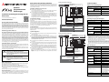
1
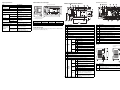
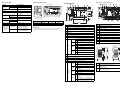
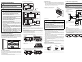
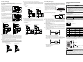
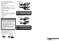
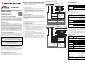
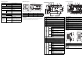
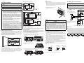
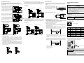
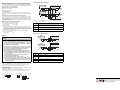
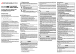
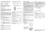
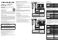
Number of output points FX3GE-24M/ 10 (16 outputs are occupied) FX3GE-40M/ 16 Circuit insulation Mechanical insulation Output form Relay Rated switching voltage max. 30 V DC max. 240 V AC Max. load Resistance load 2 A per output 8 A per group with 4 outputs Inductive load 80 VA Min. load Response time Names and Functions of Parts External dimensions and weight Mounting hole 얒 4.5 mm Specification � 82* Item � � � � � � � � � � � � � � � � 8 W1* W 86 쐅 All dimensions are in "mm". 5 V DC, 2 mA OFF ON ON OFF * Mounting hole pitches Approx. 10 ms Model name Width (W) Width (W1) Weight Output operation display LED lights when output is driven FX3GE-24M/ 130 mm 105 mm 0.60 kg Output connecting type Terminal block (M3 screws) FX3GE-40M/ 175 mm 150 mm 0.80 kg Number of output points per common terminal � View with covers removed 90 Output specifications FX3GE-24M/ FX3GE-40M/ 3 groups with one output each 1 group with 3 outputs 1 group with 4 outputs 2 groups with one output each 1 group with 2 outputs 3 groups with 4 outputs each Applicable Standard The modules of the MELSEC FX3GE series comply with the EC Directive (EMC Directive) and UL standards (UL, cUL). 씊 씉 씈 쐈 � � 쐈 쐅 쐉 No. Description No. Description � Analog input terminal block � Connector for peripheral devices (USB) � Cover of left side extension connector � Connector for peripheral devices (RS-422) � Terminal names � RUN/STOP switch � Cover (FX3GE-40M/ only) � Variable analog potentiometers (Upper: VR1, Lower: VR2) � Cover � Protective cover for lower terminals � Terminal block cover � Connector for memory cassette or display module � Input indicators � Terminals for power supply and inputs (X) � Cover of right side extension connector � Battery connector POW RUN � Status LEDs ERR ALM Power is ON. � Battery holder Power is OFF. 쐅 Terminals for service power supply and outputs (Y) PLC is running. Screw holes for the fixing of optional mounted equipment 쐈 PLC is stopped. CPU error No error Voltage of the optional battery is too low. Voltage of the optional battery is normal. 쐅 Output indicators 쐈 Model name (abbreviation) 쐉 DIN rail mounting hook 씈 Analog output terminal block 씉 RJ45 modular jack (10BASE-T/100BASE-TX interface) 100M SD/RD 씊 Ethernet status LEDs ERR Left side Program error Transmission speed 100 Mbps Transmission speed 10 Mbps or not connected Data being sent or received. Data is not sent or received. Setting error/Hardware error Communication error No error – TCP/IP: At least 1 connection is established. – UDP: At least 1 connection is open. OPEN – TCP/IP: No connection is established. – UDP: All connections are closed. : LED is ON, : LED is flashing, : LED is OFF Special adapter connector cover is removed. � � No. Description � Special adapter connector cover Remove this cover for connecting a special adapter on the left side. � Special adapter connector Used to connect special adapters to the left side of the base unit.