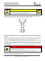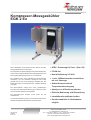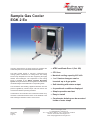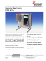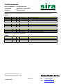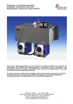
1
Bedienungs- und Installationsanleitung Installation and Operation Instructions Messgaskühler / Sample gas cooler EGK 2 Ex Lesen Sie die Bedienungsanleitung vor dem Gebrauch des Gerätes gründlich durch, insbesondere die Hinweise unter Gliederungspunkt 2. Andernfalls könnten Gesundheits- oder Sachschäden auftreten. Die Bühler Technologies GmbH haftet nicht bei eigenmächtigen Änderungen des Gerätes oder für unsachgemäßen Gebrauch. Read this instruction carefully prior to installation and/or use. Pay attention particularly to all advises and safety instructions to prevent injuries. Bühler Technologies GmbH can not be held responsible for misusing the product or unreliable function due to unauthorised modifications. BX450008, 08/2013 Art. Nr. 90 31 085 Bühler Technologies GmbH, Harkortstr. 29, D-40880 Ratingen Tel. +49 (0) 21 02 / 49 89-0, Fax. +49 (0) 21 02 / 49 89-20 Internet: www.buehler-technologies.com Email: [email protected] 1 Bedienungs- und Installationsanleitung Installation- and Operation Instruction Messgaskühler / Sample gas cooler EGK 2 Ex Inhaltsverzeichnis Seite 1 Einleitung ........................................................................................................................... 4 2 Wichtige Hinweise ............................................................................................................. 5 2.1 Allgemeine Gefahrenhinweise ...........................................................................................................6 3 Erläuterungen zum Typenschild....................................................................................... 7 4 Produktbeschreibung........................................................................................................ 7 4.1 4.2 4.3 Allgemeine Beschreibung ..................................................................................................................7 Funktionsprinzip des Kühlers ............................................................................................................8 Lieferumfang .....................................................................................................................................8 5 Transport und Lagerungsvorschriften ............................................................................. 8 6 Aufbauen und Anschließen............................................................................................... 8 6.1 6.2 6.3 6.4 7 7.1 7.2 8 8.1.1 8.1.2 8.1.3 8.2 8.2.1 8.2.2 8.2.3 8.2.4 8.3 9 9.1 9.2 Anforderungen an den Aufstellort ......................................................................................................8 Montage der Gas- und Kondensatanschlüsse ..................................................................................9 Elektrische Anschlüsse und Potentialausgleich ..............................................................................10 Prüfung des Isolationswiderstandes ................................................................................................12 Betrieb .............................................................................................................................. 13 Vor Inbetriebnahme .........................................................................................................................13 Betrieb .............................................................................................................................................13 Wartung ............................................................................................................................ 14 Test der Drucküberwachungsschaltung ......................................................................................15 Überprüfung des Anlaufkondensators / der Anlaufkondensatoren .............................................16 Reinigung des Verflüssigers (Luftwärmetauscher) .....................................................................16 Wechsel von Ersatzteilen ................................................................................................................16 Wärmetauscher ...........................................................................................................................16 Pt 100 ..........................................................................................................................................17 Elektronik .....................................................................................................................................18 Anlaufkondensator tauschen (Art.-Nr. 45 90 999 2) ....................................................................18 Ersatzteilliste....................................................................................................................................19 Fehlersuche und -behebung ........................................................................................... 20 Prüfen / Rücksetzen der Drucküberwachungsschalter ...................................................................21 Ansprechen der Druckschalter bei der ersten Inbetriebnahme .......................................................21 10 Instandsetzung und Entsorgung .................................................................................... 22 10.1 Entsorgung ......................................................................................................................................22 11 Beigefügte Dokumente.................................................................................................... 22 12 Beständigkeitsliste .......................................................................................................... 23 13 Betriebstagebuch (Kopiervorlage) ................................................................................. 24 2 BX450008, 08/2013 Art. Nr. 90 31 085 Bedienungs- und Installationsanleitung Installation- and Operation Instruction Messgaskühler / Sample gas cooler EGK 2 Ex Contents page 1 Introduction ..................................................................................................................... 25 2 Important advices ............................................................................................................ 26 2.1 General indication of risk .................................................................................................................27 3 Explanation of the type plate .......................................................................................... 28 4 Product description ......................................................................................................... 28 4.1 4.2 4.3 General description .........................................................................................................................28 Principle of function .........................................................................................................................29 Included items in delivery ................................................................................................................29 5 Transport and storing regulations ................................................................................. 29 6 Installation and connection ............................................................................................ 29 6.1 6.2 6.3 6.4 7 7.1 7.2 8 8.1 8.1.1 8.1.2 8.1.3 8.2 8.2.1 8.2.2 8.2.3 8.2.4 8.3 9 9.2 9.3 General requirements ......................................................................................................................29 Mounting ..........................................................................................................................................30 Electrical connections ......................................................................................................................31 Testing the resistance of the insulation ...........................................................................................33 Operation ......................................................................................................................... 34 Check before operation ...................................................................................................................34 Operation .........................................................................................................................................34 Maintenance ..................................................................................................................... 35 Maintenance ....................................................................................................................................36 Testing the pressure surveillance................................................................................................36 Checking the starting capacitor / capacitors ...............................................................................36 Cleaning the condenser (Air heat exchanger) .............................................................................36 Replacements of parts ....................................................................................................................36 Heat exchanger ...........................................................................................................................37 Pt 100 (Part.-Nr. 45 90 999 6) .....................................................................................................37 Electronics ...................................................................................................................................38 Replacing the starting capacitor (Part.-Nr. 45 90 999 2) .............................................................38 Spare Parts ......................................................................................................................................39 Trouble shooting and elimination .................................................................................. 40 Check / Reset of the pressure control switch ..................................................................................41 Cut off of a pressure switch at the very first start ............................................................................41 10 Repair and disposal ........................................................................................................ 42 10.1 Disposal ...........................................................................................................................................42 11 Attached documents ....................................................................................................... 42 12 List of chemical resistance ............................................................................................. 43 13 Maintenance diary (Please make copies) ...................................................................... 44 BX450008, 08/2013 Art. Nr. 90 31 085 3 Bedienungs- und Installationsanleitung Installation- and Operation Instruction Messgaskühler / Sample gas cooler EGK 2 Ex 1 Einleitung Die Messgaskühler der Baureihe EGK 2 Ex sind zum Einbau in Gasanalysensystemen bestimmt. Beachten Sie die Angaben der Datenblätter hinsichtlich spezifischen Verwendungszwecks, vorhandener Werkstoffkombinationen sowie Druck und Temperaturgrenzen. Diese Bedienungsanleitung beschreibt die Grundgeräte für die Spannungen 230 V, 50/60 Hz und 115 V, 50/60 Hz. Welchen Kühler Sie vor sich haben, ersehen Sie aus dem Typenschild. Auf diesem finden Sie neben der Auftragsnummer auch die Artikelnummer: Kühler Spannungsversorgung Artikel-Nr. EGK 2 Ex Grundgerät 230 V, 50/60 Hz 45 90 999 EGK 2 Ex Grundgerät 115 V, 50/60 Hz 45 91 999 Mit welchem Wärmetauscher-Typ und welcher Anzahl Ihr Kühler bestückt ist, hängt von Ihrer Bestellung ab. Folgende Wärmetauscher sind möglich: Wärmetauscher Material Artikel-Nr. Einsträngiger Wärmetauscher TS Edelstahl 1.4571 45 10 023 Doppelsträngiger Wärmetauscher DTS Edelstahl 1.4571 45 01 026 Einsträngiger Wärmetauscher TG Duran-Glas 45 10 013 Doppelsträngiger Wärmetauscher DTG Duran-Glas 45 01 027 Einsträngiger Wärmetauscher TV-SS Kunststoff PVDF 45 01 004 Doppelsträngiger Wärmetauscher DTV Kunststoff PVDF 45 01 028 Der Kühler muss über einen Motorschutzschalter angeschlossen werden, der als Zubehör erhältlich ist (siehe Datenblatt). Für weitere Erläuterungen dazu siehe Gliederungspunkt 6.4 „Elektrische Anschlüsse“ Bitte beachten Sie beim Anschluss die Kennwerte des Kühlers und bei Ersatzteilbestellungen die richtigen Ausführungen (Beispiel: Wärmetauscher oder Elektronik) 4 BX450008, 08/2013 Art. Nr. 90 31 085 Bedienungs- und Installationsanleitung Installation- and Operation Instruction Messgaskühler / Sample gas cooler EGK 2 Ex 2 Wichtige Hinweise HINWEIS Das Gerät ist für den Einsatz in explosionsgefährderten Bereichen zugelassen. Der Einsatz der Geräte ist nur zulässig, wenn: - das Produkt unter den in der Bedienungs- und Installationsanleitung beschriebenen Bedingungen, dem Einsatz gemäß Typenschild und für Anwendungen, für die es vorgesehen ist, verwendet wird. - Überwachungsvorrichtungen/ Schutzvorrichtung korrekt angeschlossen sind. - die Service- und Reparaturarbeiten von Bühler Technologies GmbH durchgeführt werden, soweit sie nicht in dieser Anleitung beschrieben sind. - Originalersatzteile verwendet werden. Das Errichten elektrischer Anlagen in explosionsgefährdeten Bereichen erfordert in Deutschland die Beachtung folgender Vorschriften: - EN 60079-14 / VDE 0165-1 „Explosionsfähige Atmosphäre - Teil 14: Projektierung, Auswahl und Errichtung elektrischer Anlagen“, - Betriebssicherheitsverordnung (BetrSichV) - Gefahrenstoffverordnung (GefStoffV) - Im Ausland sind die entsprechenden Landesvorschriften zu beachten. Diese Bedienungsanleitung ist Teil des Betriebsmittels. Der Hersteller behält sich das Recht vor, die Leistungs-, die Spezifikations- oder die Auslegungsdaten ohne Vorankündigung zu ändern. Bewahren Sie die Anleitung für den späteren Gebrauch auf. Begriffsbestimmungen für Warnhinweise: HINWEIS Signalwort für wichtige Information zum Produkt auf die im besonderen Maße aufmerksam gemacht werden soll. VORSICHT Signalwort zur Kennzeichnung einer Gefährdung mit geringem Risiko, die zu einem Sachschaden oder leichten bis mittelschweren Körperverletzungen führen kann, wenn sie nicht vermieden wird. WARNUNG Signalwort zur Kennzeichnung einer Gefährdung mit mittlerem Risiko, die möglicherweise Tod oder schwere Körperverletzungen zur Folge hat, wenn sie nicht vermieden wird. GEFAHR Signalwort zur Kennzeichnung einer Gefährdung mit hohem Risiko, die unmittelbar Tod oder schwere Körperverletzung zur Folge hat, wenn sie nicht vermieden wird. Warnung vor einer allgemeinen Gefahr Warnung vor explosions-gefährdeten Bereichen Netzstecker ziehen Warnung vor elektrischer Spannung Warnung vor heißer Oberfläche Atemschutz tragen Warnung vor dem Einatmen giftiger Gase Gesichtsschutz tragen Warnung vor ätzenden Flüssigkeiten Handschuhe tragen BX450008, 08/2013 Art. Nr. 90 31 085 5 Bedienungs- und Installationsanleitung Installation- and Operation Instruction Messgaskühler / Sample gas cooler EGK 2 Ex 2.1 Allgemeine Gefahrenhinweise Das Gerät darf nur von Fachpersonal installiert werden, das mit den Sicherheitsanforderungen und den Risiken vertraut ist. Beachten Sie unbedingt die für den Einbauort relevanten Sicherheitsvorschriften und allgemein gültigen Regeln der Technik. Beugen Sie Störungen vor und vermeiden Sie dadurch Personen- und Sachschäden. Der für die Anlage Verantwortliche muss sicherstellen, dass: - Sicherheitshinweise und Betriebsanleitungen verfügbar sind und eingehalten werden, - Unfallverhütungsvorschriften der Berufsgenossenschaften beachtet werden; in Deutschland: „Grundsätze der Prävention“ (BGV A1) und “Elektrische Anlagen und Betriebsmittel (BGV A3)”, - die Prüfungen vor Inbetriebnahme und wiederkehrende Prüfungen nach Betriebssicherheitsverordnung (BetrSichV) durchgeführt werden, - die zulässigen Daten und Einsatzbedingungen eingehalten werden, - Schutzeinrichtungen verwendet werden und vorgeschriebene Wartungsarbeiten durchgeführt werden, - bei der Entsorgung die gesetzlichen Regelungen beachtet werden. Wartung, Reparatur: - Reparaturen an den Betriebsmitteln dürfen nur von Bühler autorisiertem Personal ausgeführt werden. - Nur Umbau-, Wartungs- oder Montagearbeiten ausführen, die in dieser Bedienungs- und Installationsanleitung beschrieben sind. - Nur Original-Ersatzteile verwenden. Bei Durchführung von Wartungsarbeiten jeglicher Art müssen die relevanten Sicherheits- und Betriebsbestimmungen beachtet werden. ! GEFAHR Elektrische Spannung Gefahr eines elektrischen Schlages. Trennen Sie das Gerät bei allen Arbeiten vom Netz. Sichern Sie das Gerät gegen unbeabsichtigtes Wiedereinschalten. Das Gerät darf nur von instruiertem, fachkundigem Personal geöffnet werden. ! GEFAHR Giftige, ätzende Gase Messgas kann gesundheitsgefährdend sein. Sorgen Sie ggf. für eine sichere Ableitung des Gases. Stellen Sie vor Beginn der Wartungsarbeiten die Gaszufuhr ab und sichern Sie sie gegen unbeabsichtigtes Aufdrehen. Schützen Sie sich bei der Wartung vor giftigen / ätzenden Gasen. Tragen Sie die entsprechende Schutzausrüstung. ! GEFAHR Explosionsgefahr Lebens- und Explosionsgefahr durch Gasaustritt bei nicht bestimmungsgemäßem Betrieb. Setzen Sie das Gerät nur wie in dieser Anleitung beschrieben ein. Beachten Sie die Prozessbedingungen. Prüfen Sie die Dichtigkeit der Leitungen. 6 BX450008, 08/2013 Art. Nr. 90 31 085 Bedienungs- und Installationsanleitung Installation- and Operation Instruction Messgaskühler / Sample gas cooler EGK 2 Ex WARNUNG ! Bruchgefahr Schützen Sie das Betriebsmittel ist vor externen Schlageinwirkungen. Schützen Sie das Gerät vor fallenden Gegenständen. 3 Erläuterungen zum Typenschild Hersteller mit Anschrift Typbezeichnung Messgaskühler EGK 2 Ex Zündschutzkennzeichnung II 2G Ex px e mb q [ia] IIC T4 Gb A345678/001 45 90 999 Bj: 2011 Serien Nr., Artikel Nr. und Baujahr 230V 50/60Hz Spannung ce0158 BVS 03 ATEX E 301 X Zulassungsnummer 4 Produktbeschreibung 4.1 Allgemeine Beschreibung Ein Messgaskühler dient zur Absenkung des Feuchtigkeitsgehaltes und damit des Taupunktes in einem Messgas. Hierdurch sollen zum einen Messungenauigkeiten durch Volumeneinflüsse gesenkt werden, zum anderen soll vermieden werden, dass Feuchtigkeit im weiteren Messweg kondensiert und Schäden hervorruft, insbesondere an der empfindlichen Messzelle des Analysators. Der Messgaskühler ist somit Teil einer Aufbereitung, die im Folgenden als typischer Flussplan dargestellt ist. Testgas/ calibration gas 8 1 2 3 4 5 6 7 9 10 1) 2) 3) 4) 5) 6) 7) 8) 9) 10) Entnahmesonde Leitung Umschalthahn zur Kalibrierung Gaspumpe Gaskühler EGK 2 Ex Kondensatableiter Feinfilter Feuchtefühler Durchflussmesser mit Regelventil Analysator Der Kühlkreislauf kühlt einen Kühlblock (am Gerät vorne links) auf eine definierte Temperatur ab. In diesen Kühlblock werden die eigentlichen Wärmetauscher gesteckt, die dadurch ebenfalls abgekühlt werden. Das warme, „feuchte“ Messgas wird oben in den Eingang des Wärmetauschers eingeleitet, wird in diesem abgekühlt und verlässt ihn dann wieder oben am Ausgang. Der Wasserdampf kondensiert an den kühlenden Oberflächen des Wärmetauschers und läuft nach unten ab, wo der Kondensatausgang des Wärmetauschers ist. Von dort kann dann das Kondensat mittels Gefäß gesammelt oder mit automatischem Kondensatableiter oder peristaltischer Pumpe direkt abgeführt werden. Ein automatischer Kondensatableiter ist nur möglich, wenn im Wärmetauscher Überdruck herrscht. Für die Wärmetauscher stehen verschiedene Typen und Materialien zur Verfügung, wie bereits in der Einleitung beschrieben. Beachten Sie bei der Auswahl insbesondere die Beständigkeit (z.B. Tabelle unter 12) und die zulässigen Drücke (im beigefügten Datenblatt) BX450008, 08/2013 Art. Nr. 90 31 085 7 Bedienungs- und Installationsanleitung Installation- and Operation Instruction Messgaskühler / Sample gas cooler EGK 2 Ex 4.2 Funktionsprinzip des Kühlers Der Kühlkreislauf ist im Prinzip wie ein Kühlschrank aufgebaut. Anstelle des gekühlten Innenraums steht hier der oben genannte Kühlblock. Ein Kompressor wird innerhalb eines Toleranzbereiches ein- bzw. ausgeschaltet. Der Betriebszustand des Kühlers wird durch eine LED angezeigt, wobei grün bedeutet, dass der Kühler im Arbeitsbereich ist, und rot, dass er außerhalb dieses Bereiches ist oder ein Fehlerfall vorliegt. Die Elektronik stellt diese Unterscheidung auch als potentialfreien Ausgang zur Verfügung, der in Fail-safe-Schaltung betrieben ist. Dadurch wird einer Leitwarte auch ein Stromausfall angezeigt. Innerhalb der beiden Bereiche kann die LED auf Dauerlicht sein oder blinken. Die genaue Beschreibung der verschiedenen dargestellten Zustände ist unter 7.2 „Betrieb“ beschrieben. 4.3 Lieferumfang Zum Lieferumfang gehört das Grundgerät in der bestellten Spannung, die bestellten Wärmetauscher und der gegebenenfalls bestellte Motorschutzschalter. Sofern letzterer nicht mitbestellt wurde, ist ein Motorschutzschalter zu verwenden, der den Parametern der Zulassung entspricht (siehe Gliederungspunkt 6.4 „Elektrischer Anschluss“). 5 Transport und Lagerungsvorschriften Der Messgaskühler darf nur in der Originalverpackung oder einem geeigneten Ersatz transportiert werden. Er muss senkrecht transportiert werden. Legen Sie ihn auf keinen Fall beim Transport, da sonst das Öl aus dem Kompressor in den Kühlkreislauf fließen könnte. Dies kann zu Anlaufproblemen oder zu Ausfall des Kühlers führen. Bei längerer Nichtbenutzung ist der Kühler gegen Feuchtigkeit und Wärme zu schützen. Er muss in einem überdachten, trockenen, vibrations- und staubfreien Raum bei einer Temperatur von -20°C bis +40°C aufbewahrt werden. 6 Aufbauen und Anschließen 6.1 Anforderungen an den Aufstellort Das Gerät ist für den Einsatz in geschlossenen Räumen vorgesehen. Beim Einsatz im Freien ist ein ausreichender Wetterschutz vorzusehen. Die zulässigen Umgebungsbedingungen für den explosionsgefährdeten Bereich gemäß angehängtem Datenblatt sind einzuhalten. Der Messgaskühler ist als Standgerät verwendbar oder an die Wand zu montieren. Die Konvektion darf nicht behindert werden. Rund um die Kühlerunterseite ist ein Abstand anderer Gegenstände von mindestens 10 cm einzuhalten. Oberhalb des Kühlers, insbesondere der Lüftungsöffnung hinten, ist ein Abstand von mindestens 30 cm einzuhalten. Beachten Sie für Ihre oberhalb montierten Komponenten, dass die nach oben aus dem Kühler austretende Luft stark erwärmt sein kann. Bei Montage in geschlossenen Gehäusen, z.B. Analysenschränken, ist für eine ausreichende Entlüftung zu sorgen. Reicht die Konvektion nicht aus, empfehlen wir, den Schrank mit Luft zu spülen oder einen Ventilator vorzusehen, um die Innentemperatur zu senken. Wird der Messgaskühler als Wandgerät verwendet, muss gewährleistet sein, dass die Trag- und Standfestigkeit der Wand bzw. des Schrankes ausreichen. 8 BX450008, 08/2013 Art. Nr. 90 31 085 Bedienungs- und Installationsanleitung Installation- and Operation Instruction Messgaskühler / Sample gas cooler EGK 2 Ex 6.2 Montage der Gas- und Kondensatanschlüsse ! VORSICHT Explosionsgefahr Vor Einsatz von Zubehörteilen ist zu prüfen, ob diese Teile für den Einsatzzweck geeignet sind (Ex-Zone / Kategorie, Beständigkeiten) Bei Wärmetauschern aus Glas ist bei dem Anschluss der Gasleitungen auf die richtige Lage der Dichtung zu achten. Die Dichtung besteht aus einem Silikonring mit einer Stulpe aus PTFE. Die PTFE-Seite muss zum Glasgewinde zeigen. Glas A000268 PTFE Die Gaszuführung ist bis zum Kühler mit Gefälle zu verlegen. Bei großem Kondensatanfall empfehlen wir, eine Kondensatvorabscheidung vor dem Kühler einzusetzen. Hierzu eignen sich unsere Flüssigkeitsabscheider mit automatischer Kondensatentleerung 11 LD spez., AK 20 V oder Typ 165. Die Gaseingänge am Wärmetauscher sind mit „E“ gekennzeichnet und/oder rot markiert, die Ausgänge sind mit „A“ gekennzeichnet. Bei Einsatz von Glas- oder PVDF-Wärmetauschern ist die mitgelieferte Schutzhaube zu verwenden. Hierbei Schutzhaube abnehmen, die Schläuche durch die Schutzhaube ziehen, dann die Schläuche an die Wärmetauscher anschließen und schließlich die Haube wieder aufsetzen und anschrauben. Gehen Sie beim Anschluss der Glas- und PVDF-Wärmetauscher vorsichtig vor und ziehen Sie die Verschraubungen nur von Hand an. ! GEFAHR Explosionsgefahr durch Flammdurchschlag Schwere Verletzungen und Schäden an der Anlage Installieren Sie bei Gefahr eines Flammdurchschlags aus dem Prozess ist eine Flammsperre. Bei Verwendung von automatischen Kondensatableitern muss die Gaspumpe vor dem Kühler montiert werden, da sonst die Funktion der Kondensatableiter nicht mehr gewährleistet ist. Befindet sich die Messgaspumpe am Ausgang des Kühlers (Saugbetrieb), ist der Einsatz von Kondensatsammelgefäßen aus Glas oder der Einsatz von peristaltischen Pumpen zu empfehlen. BX450008, 08/2013 Art. Nr. 90 31 085 9 Bedienungs- und Installationsanleitung Installation- and Operation Instruction Messgaskühler / Sample gas cooler EGK 2 Ex Für die Kondensatableitung stehen Glasgefäße und automatische Kondensatableiter zur Verfügung, die extern unterhalb des Gerätes zu montieren sind. Anschluss der Kondensatableiter: je nach Werkstoff eine Verbindungsleitung aus Verschraubung und Rohr oder Schlauch zwischen Wärmetauscher und Kondensatableiter herstellen. Bei Edelstahl kann der Kondensatableiter direkt am Verbindungsrohr aufgehängt werden, bei Schlauchleitungen ist der Kondensatableiter mittels einer Schelle separat zu befestigen. Kondensatleitungen sind grundsätzlich mit Gefälle und Mindestnennweite DN 8/10 zu verlegen. Bei Verwendung einer externen peristaltischen Pumpe kann diese auch etwas entfernt vom Kühler befestigt werden. Achten Sie darauf, dass die Anschlüsse an den Gasleitungen dicht sind. 6.3 Elektrische Anschlüsse und Potentialausgleich ! GEFAHR Gefährliche Spannung Gefahr eines elektrischen Schlages. Trennen Sie bei Arbeiten an elektrischen Betriebsmitteln diese vom Stromnetz. Stellen Sie sicher, dass das Betriebsmittel nicht unbeabsichtigt wieder unter Spannung gesetzt werden kann. Achten Sie auf die korrekte Spannungsversorgung. HINWEIS Bei Einsatz in explosionsgefährdeten Bereichen: Das Errichten elektrischer Anlagen in explosionsgefährdeten Bereichen erfordert in Deutschland die Beachtung folgender Vorschriften: - EN 60079-14 / VDE 0165-1 „Explosionsfähige Atmosphäre - Teil 14: Projektierung, Auswahl und Errichtung elektrischer Anlagen“, - Betriebssicherheitsverordnung (BetrSichV) - Gefahrenstoffverordnung (GefStoffV) Im Ausland sind die entsprechenden nationalen Vorschriften zu beachten. Der Messgaskühler muss über einen geeigneten Überlastschutz (Motorschutzschalter gemäß Zulassung) abgesichert werden. Hier muss ein Motorschutzschalter verwendet werden, der für Geräte im Ex-Bereich nach ATEX zugelassen ist. Einen solchen Motorschutzschalter erhalten Sie als Zubehör (siehe angehängtes Datenblatt). Die Zuleitungsquerschnitte sind der Bemessungsstromstärke anzupassen. Außerdem sind die Absicherungsbedingungen einzuhalten, wie Sie in der Baumusterprüfbescheinigung angegeben sind (siehe Anhang). Der Statusausgang kann auch an einen eigensicheren Eingang angeschlossen werden. Die Bedingungen dieses Eingangs sind einzuhalten. Kapazität und Induktivität des Kontaktes sind null, so dass nur das verwendete Kabel berücksichtigt werden muss. 10 BX450008, 08/2013 Art. Nr. 90 31 085 Bedienungs- und Installationsanleitung Installation- and Operation Instruction Messgaskühler / Sample gas cooler EGK 2 Ex Anschluss des Kühlers: Lösen Sie am schwarzen Elektrikgehäuse die vier Schrauben in den Ecken der Front. Heben Sie den Deckel vorsichtig ab: Die Bedienelemente sind mit Kabeln an der Elektronik angebracht. Drehen Sie den Deckel und legen Sie ihn auf dem Kühler ab. Achten Sie darauf, dass die Kabel nicht auf Zug belastet werden. Führen Sie das Kabel für das Statussignal an der vorderen linken und das Kabel für die Versorgungsspannung durch die vordere mittlere Kabelverschraubung. Schließen Sie die Verbindungen gemäß Zeichnung 47/027-08-3 im Anhang an. Die einzelnen Adern müssen nur 5mm abisoliert werden. Benutzen Sie keine Aderendhülsen. Beachten Sie insbesondere die Erdverbindung der Netzzuleitung: Auf dem Gewindebolzen rechts unten im Gehäuse sind alle Einzelteile bereits montiert: Lösen Sie die Mutter und nehmen Sie Mutter, Scheiben und Ringkabelschuh ab. Bringen Sie den Ringkabelschuh an der Erdader des Netzkabels an. Schieben Sie Scheiben und Ringkabelschuh in der Reihenfolge Scheibe – Ringkabelschuh – Scheibe – Zahnscheibe auf und ziehen Sie die Mutter fest an. Verschließen Sie nun das Gehäuse wieder unter Berücksichtigung der folgenden Punkte: Im Anschlusskasten des Messgaskühlers dürfen sich keine Fremdkörper, Schmutz sowie Feuchtigkeit befinden. Kasten staub- und wasserdicht verschließen (Darauf achten, dass keine Kabel eingequetscht werden). Bei Schließen des Anschlusskastens die Original-Dichtung verwenden. Nicht genutzte Öffnungen sind nach Atex mit zugelassenen Stopfen zu verschließen. Alle Verschraubungen sind dichtzuziehen. Schließen Sie den Potentialausgleich des Kühlers (Gewindebolzen unterhalb des Elektrikgehäuses) an den örtlichen Potentialausgleich an. Elektrische Ausgleichströme dürfen nicht über diesen Anschluss gehen. BX450008, 08/2013 Art. Nr. 90 31 085 11 Bedienungs- und Installationsanleitung Installation- and Operation Instruction Messgaskühler / Sample gas cooler EGK 2 Ex 6.4 Prüfung des Isolationswiderstandes ! WARNUNG Beschädigung des Gerätes bei Durchführung der Isolationsprüfung Führen Sie keine Prüfung der Spannungsfestigkeit mit Hochspannung am Gesamtgerät durch! Das Gerät ist mit umfangreichen EMV-Schutzmaßnahmen ausgerüstet. Bei einer Prüfung der Spannungsfestigkeit werden elektronische Filterbauteile beschädigt. Die notwendigen Prüfungen wurden bei allen zu prüfenden Baugruppen werkseitig durchgeführt (Prüfspannung 1,5 kV). Sofern Sie die Spannungsfestigkeit selbst nochmals prüfen wollen, führen Sie diese nur an den folgenden Einzelkomponenten durch. Beachten Sie dabei die folgenden Hinweise. Zur Prüfung der Kühlerelektronik klemmen Sie die Erdverbindung an der Kühlerelektronik ab. Schließen Sie L und N kurz und führen Sie den Hochspannungstest gegen Erde durch. HINWEIS Klemmen Sie nach dieser Prüfung unbedingt die Erdverbindung wieder an! Zur Prüfung des Kompressors, klemmen Sie dessen Versorgungsleitung an der Reglerelektronik ab. Die Erdverbindung wird nicht getrennt. Schließen Sie die Hauptwicklung, Nebenwicklung und N kurz und führen Sie dann die Spannungsfestigkeitsprüfung gegen Erde durch. Klemmen Sie nach der Prüfung den Kompresser wieder an. Zur Prüfung der Anlaufkondensatoren, klemmen Sie deren Versorgungsleitung an der Reglerelektronik ab. Die Erdverbindung wird nicht getrennt. Schließen Sie die Versorgungsleitungen kurz und führen Sie dann die Spannungsfestigkeitsprüfung gegen Erde durch. Klemmen Sie nach der Prüfung den/die Anlaufkondensatoren wieder an. 12 BX450008, 08/2013 Art. Nr. 90 31 085 Bedienungs- und Installationsanleitung Installation- and Operation Instruction Messgaskühler / Sample gas cooler EGK 2 Ex 7 Betrieb Der Messgaskühler darf nicht außerhalb seiner Spezifikationen betrieben werden. ! VORSICHT Heiße Oberfläche Verbrennungsgefahr Im Betrieb kann je nach Betriebsparametern eine Temperatur von bis zu 80°C an dem Luftwärmetauscher im hinteren Bereich des Kühlers entstehen. 7.1 Vor Inbetriebnahme Kontrollieren Sie: - die Schlauch- und Elektroanschlüsse auf Unversehrtheit und korrekte Montage. - dass keine Teile des Messgaskühlers demontiert sind (z.B. Deckel). - dass die Schutz- und Überwachungsvorrichtungen vorhanden und funktionsfähig sind (Motorschutzschalter). - die Umgebungsparameter eingehalten werden. - Leistungsschildangaben beachten! - ob Spannung und Frequenz des Motors mit Netzwerten übereinstimmen. - ob die elektrischen Anschlüsse fest angezogen und ob die Überwachungseinrichtungen vorschriftsmäßig angeschlossen und eingestellt sind! - ob Lufteintrittsöffnungen und Kühlflächen sauber sind und die Lüftführung nicht behindert ist (siehe 6.1)! - ob Schutzmaßnahmen durchgeführt sind; Potentialausgleich! - ob der Kühler ordnungsgemäß befestigt ist! - ob der Anschlusskastendeckel verschlossen ist und die Leitungseinführungen sachgemäß abgedichtet sind. - Der Motorschutzschalter muss auf den Nennstrom eingestellt werden: - bei 230 V- Version: 1,3 A - bei 115 V-Version: 3,2 A 7.2 Betrieb Netzspannung zuschalten; die Leuchte blinkt jetzt rot. Taster „Start1“ und „Start2“ nacheinander drücken; der Kühler läuft jetzt an und die Leuchte zeigt dauernd rot. Nach einiger Zeit (ca. 10 Minuten je nach Umgebungstemperatur) wechselt die Leuchte auf grün blinkend. Der Statusausgang schaltet. Der Arbeitsbereich (±3K um die eingestellte Temperatur (i.d.R. 5°C)) ist nun erreicht. Der Kühler kühlt noch weiter. Nach einiger Zeit ist der Arbeitspunkt erreicht und der Kompressor schaltet ab. Die Leuchte zeigt dauernd grün. Sobald die Temperatur im Kühlblock wieder angestiegen ist, startet der Kompressor wieder und die Leuchte blinkt wieder grün. BX450008, 08/2013 Art. Nr. 90 31 085 13 Bedienungs- und Installationsanleitung Installation- and Operation Instruction Messgaskühler / Sample gas cooler EGK 2 Ex 8 Wartung - Das Gerät darf nicht außerhalb seiner Spezifikationen betrieben werden. - Reparaturen an den Betriebsmitteln dürfen nur von Bühler autorisiertem Personal ausgeführt werden. - Führen Sie nur Umbau-, Wartungs- oder Montagearbeiten aus, die in dieser Bedienungs- und Installationsanleitung beschrieben sind. - Defekte Teile sind umgehend auszutauschen und das Gerät bzw. der Gasweg außer Betrieb zu setzen. - Verwenden Sie nur Original-Ersatzteile. - Beachten Sie bei der Durchführung von Wartungsarbeiten jeglicher Art die relevanten Sicherheits- und Betriebsbestimmungen. ! GEFAHR Elektrische Spannung Gefahr eines elektrischen Schlages. Trennen Sie das Gerät bei allen Wartungsarbeiten vom Netz. Sichern Sie das Gerät gegen unbeabsichtigtes Wiedereinschalten. Der Anschluss darf nur von geschultem Fachpersonal vorgenommen werden. Achten Sie auf die korrekte Spannungsversorgung! ! GEFAHR Giftige, ätzende Gase Messgas kann gesundheitsgefährdend sein. Schalten Sie vor Beginn der Wartungsarbeiten die Gaszufuhr ab und spülen Sie die Gasleitungen ggf. mit Luft. Bitte sorgen Sie ggf. für eine sichere Ableitung des Gases. Schützen Sie sich bei der Wartung vor giftigen / ätzenden Gasen. Tragen Sie die entsprechende Schutzausrüstung. ! VORSICHT Gasaustritt Die Wärmetauscher dürfen beim Ausbau nicht unter Druck stehen. ! VORSICHT Kippgefahr Sachschäden am Gerät Sichern Sie das Gerät gegen Umfallen, Wegrutschen und Runterfallen, wenn Sie an ihm arbeiten. 14 BX450008, 08/2013 Art. Nr. 90 31 085 Bedienungs- und Installationsanleitung Installation- and Operation Instruction Messgaskühler / Sample gas cooler EGK 2 Ex ! VORSICHT Heiße Oberfläche Verbrennungsgefahr Im Betrieb kann je nach Betriebsparametern eine Temperatur von bis zu 80°C an dem Luftwärmetauscher im hinteren Bereich des Kühlers entstehen. Lassen Sie das Gerät erst abkühlen, bevor Sie mit den Wartungsarbeiten beginnen. HINWEIS - Vor dem Öffnen des Elektronikgehäuses muss eine Wartezeit von mindestens einer Minute eingehalten werden - Vor Entfernen der Gasanschlüsse oder der Kondensatableitungsbauteile Gaszufluss absperren. - Defekte Teile sind umgehend auszutauschen und der Kühler bzw. der Messweg außer Betrieb zu setzen - Die Funktionsprüfung der Sicherheitsstromkreise ist einmal jährlich durchzuführen. Sollte die Prüfung negativ verlaufen, ist das Gerät zum Hersteller einzuschicken. - Kühler immer senkrecht transportieren. - Unbedingt die Bedingungen der Baumusterprüfbescheinigung einhalten (siehe Anhang) Wartungsarbeiten Die nachfolgenden Überprüfungen und gegebenenfalls die Reinigung sind mindestens einmal im Jahr durchzuführen. Weitere Wartungsschritte sind nicht notwendig. Sie sollten über die Durchführung eine Nachweisdokumentation führen. Ein Betriebstagebuch ist als Kopiervorlage am Ende der Bedienungsanleitung vorhanden. ! GEFAHR Funkenbildung durch elektrostatische Aufladung Reinigen Sie Gehäuseteile aus Kunststoff und Aufkleber nur mit einem feuchten Tuch. Verbinden Sie metallische Gehäuse mit Erdpotential (PE) leitend! 8.1.1 Test der Drucküberwachungsschaltung Der Kühler muss laufen und im Arbeitsbereich sein (Anzeige grün). Drücken Sie den Taster „Test1“. Der Kühler schaltet ab und die LED blinkt rot. Drücken Sie den Taster „Start1“. Der Kühler schaltet wieder ein und die LED wird grün. Drücken Sie den Taster „Test2“. Der Kühler schaltet ab und die LED blinkt rot. Drücken Sie den Taster „Start2“. Der Kühler schaltet wieder ein und die LED wird grün. BX450008, 08/2013 Art. Nr. 90 31 085 15 Bedienungs- und Installationsanleitung Installation- and Operation Instruction Messgaskühler / Sample gas cooler EGK 2 Ex 8.1.2 Überprüfung des Anlaufkondensators / der Anlaufkondensatoren An der rechten Seite des Messgaskühlers sind zwei ovale Ausschnitte. Durch diese sehen Sie die Öffnungen des Anlaufkondensators, die mit einem Klebeband abgedichtet sind. Dieses Klebeband muss unbeschädigt sein und auf der gesamten Fläche kleben. 8.1.3 Reinigung des Verflüssigers (Luftwärmetauscher) Von oben sehen Sie im hinteren Bereich des Messgaskühlers die Rippen des Verflüssigers. Diese sollten sauber sein. Eine Reinigung ist nur notwendig, wenn größere Mengen Staub oder Ablagerungen dort zu sehen sind. Reinigen Sie vorsichtig mit Druckluft. Auf keinen Fall sollten Sie aggressive Reinigungsmittel einsetzen. 8.2 Wechsel von Ersatzteilen HINWEIS In der Regel sollten keine Teile an dem Messgaskühler defekt sein. Wir empfehlen, einen Austausch von Pt100, Elektronik oder Anlaufkondensator nur durch das Herstellerwerk oder einen geschulten Kundendienst durchführen zu lassen. Sie können einen Austausch gemäß nachfolgender Beschreibung durchführen. Die Firma Bühler Technologies GmbH muss in diesem Fall eine Verantwortung für unsachgemäßen Austausch allerdings ablehnen. 8.2.1 Wärmetauscher Den Typ des Wärmetauschers entnehmen Sie der Artikelnummer, siehe 1. „Einleitung“. Wärmetauscher müssen nur ausgetauscht werden, wenn sie sich zugesetzt haben oder beschädigt wurden. Sollten sie sich zugesetzt haben, empfehlen wir zu prüfen, ob sich dies in Zukunft durch den Einsatz eines Filters vermeiden lässt. 16 Warnhinweise unter 8. beachten. Anlage spannungsfrei schalten und drucklos machen. Gasverbindungen und Kondensatablauf lösen. Wärmetauscher nach oben herausziehen. Kühlnest (Loch im Kühlblock) reinigen. Neuen Wärmetauscher an der gekühlten Außenfläche mit Silikonfett einschmieren. Wärmetauscher mit drehender Bewegung in das Kühlnest wieder einschieben. Anschlüsse nach 6.3 wiederherstellen. BX450008, 08/2013 Art. Nr. 90 31 085 Bedienungs- und Installationsanleitung Installation- and Operation Instruction Messgaskühler / Sample gas cooler EGK 2 Ex 8.2.2 Pt 100 Art. Nr. 45 90 999 6 Warnhinweise unter 8. beachten. Anlage spannungsfrei schalten (Versorgung und Statusausgang) und drucklos machen. Vier Schrauben in den Ecken der Front am schwarzen Elektrikgehäuse lösen. Deckel vorsichtig abheben: Die Bedienelemente sind mit Kabeln an der Elektronik angebracht. Deckel drehen und auf dem Kühler ablegen. Achten Sie darauf, dass die Kabel nicht auf Zug belastet werden. Adern des Pt100 aus den Klemmen lösen (obere Reihe ganz links, siehe Zeichnung 47/027-08-3 im Anhang) und Widerstand messen. Er sollte je nach seiner Temperatur zwischen ca. 102..110 Ohm liegen. Bei wesentlichen Abweichungen ist er defekt. Abdeckhaube für die Pressostaten entfernen. Dazu die zwei Schrauben herausdrehen, den unteren Teil vorsichtig nach vorne ziehen und die Haube nach oben wegschieben. Sie sehen nun die beiden Pressostaten. Verschraubung des Pt100 unterhalb des Kühlblockes lösen und den Pt 100 vorsichtig herausziehen. Verschraubung für das Kabel des Pt 100 am Elektronikgehäuse lösen und das Kabel aus dem Elektronikgehäuse herausziehen. Verschraubung an dem Winkel unterhalb der Pressostaten lösen, Kabel vorsichtig nach links herausziehen. Neuen Pt 100-Fühler durch die Verschraubung und mit ein wenig Silikonfett einsetzen – Ziehen Sie die Verschraubung noch nicht an. Kabel durch die Verschraubung unten führen, hinter den Pressostaten durch und in die Verschraubung am Gehäuse. Vergessen Sie hierbei nicht die Muttern und die Gummiringe. Pt-100 anklemmen (siehe Zeichnung 47/027-08-3 im Anhang) Kabel ausrichten, dass es spannungsfrei liegt. Die drei Verschraubungen anziehen. Abdeckung für die Pressostaten wieder aufsetzen. Gehäuse wieder unter Berücksichtigung der folgenden Punkte verschließen: Im Anschlusskasten des Messgaskühlers dürfen sich keine Fremdkörper, Schmutz sowie Feuchtigkeit befinden. Kasten staub- und wasserdicht verschließen (Darauf achten, dass keine Kabel eingequetscht werden) Kühler nun nach 7.2 wieder in nehmen Betrieb. Beobachten Sie, ob Kühler in den Arbeitsbereich läuft BX450008, 08/2013 Art. Nr. 90 31 085 17 Bedienungs- und Installationsanleitung Installation- and Operation Instruction Messgaskühler / Sample gas cooler EGK 2 Ex 8.2.3 Elektronik Auf korrekte Spannung achten: 230 V: 115 V: Warnhinweise unter 8. beachten. Art. Nr. 45 90 999 7; Art. Nr. 45 91 999 7 Anlage spannungsfrei schalten (Versorgung und Statusausgang) und drucklos machen. Vier Schrauben in den Ecken der Front am schwarzen Elektrikgehäuse lösen. Deckel vorsichtig abheben: Die Bedienelemente sind mit Kabeln an der Elektronik angebracht. Deckel drehen und auf dem Kühler ablegen. Achten Sie darauf, dass die Kabel nicht auf Zug belastet werden. Alle Kabel abklemmen. Obwohl die Kabel farblich kodiert sind, sollten Sie die Adern markieren, wenn Sie unsicher sind. 4 Schrauben an der Oberseite der Platine lösen. Die Elektronik lässt sich nun herausnehmen. Neue Elektronik mittels der 4 Schrauben einbauen. Alle Adern nach Zeichnung 47/027-08-3 im Anhang wieder anschließen, die Kabelfarben sind dort gegeben. Gehäuse wieder unter Berücksichtigung der folgenden Punkte verschließen: Im Anschlusskasten des Messgaskühlers dürfen sich keine Fremdkörper, Schmutz sowie Feuchtigkeit befinden. Kasten staub- und wasserdicht verschließen (Darauf achten, dass keine Kabel eingequetscht werden) Kühler nun nach 7.2 wieder in nehmen Betrieb. Test nach „8.1 Wartung“ durchführen. Kühler arbeiten lassen und prüfen, ob er den Arbeitsbereich erreicht. 8.2.4 Anlaufkondensator tauschen (Art.-Nr. 45 90 999 2) Nur notwendig, wenn Überprüfung Beschädigung des Klebestreifens ergeben hat Warnhinweise unter 8. beachten. 18 Anlage spannungsfrei schalten (Versorgung und Statusausgang) und drucklos machen. Gasanschlüsse entfernen. Kühler ausbauen und sicher abstellen. Vier Schrauben in den Ecken der Front am schwarzen Elektrikgehäuse lösen. Deckel vorsichtig abheben: Die Bedienelemente sind mit Kabeln an der Elektronik angebracht. Deckel drehen und auf dem Kühler ablegen. Achten Sie darauf, dass die Kabel nicht auf Zug belastet werden. Das / die Kabel des Kondensators / der Kondensatoren abklemmen, Erdpunkt auseinander nehmen. (vgl. Zeichnung 47/027-08-3 im Anhang). Verschraubung des Kondensators Lösen und Kabel herausziehen. Rückwand des Kühlers abschrauben. Halteblech der Anlaufkondensatoren unten links lösen. Halteblech mit den Kondensatoren herausziehen. Mutter des auszutauschenden Kondensators lösen und den Kondensator entfernen. Kabel des neuen Kondensators entsprechend dem alten Kondensators ablängen, Kabelschuh aber noch nicht anquetschen. BX450008, 08/2013 Art. Nr. 90 31 085 Bedienungs- und Installationsanleitung Installation- and Operation Instruction Messgaskühler / Sample gas cooler EGK 2 Ex Neuen Kondensator mit der Mutter einbauen, die Mutter noch nicht ganz anziehen Das / die Kabel durch die Durchführungstüllen des Kamins führen. Halteblech und Kondensator(en) in den Kamin einschieben. Haltewinkel anschrauben; Klebestreifen der Kondensatoren nach dem Sichtfenster in der Seite des Kamins ausrichten, Mutter des Kondensators anziehen. Rückwand anschrauben. Kabel durch die Verschraubungen führen, Mutter und Gummiring nicht vergessen. Kabelschuh an die Erd-Ader des Kabels anquetschen. Den / die Kondensatoren gemäß Zeichnung 47/027-08-3 im Anhang anschließen. ! Der Erdpunkt ist so aufzubauen wie in der Zeichnung angegeben. Gehäuse wieder unter Berücksichtigung der folgenden Punkte verschließen: Im Anschlusskasten des Messgaskühlers dürfen sich keine Fremdkörper, Schmutz sowie Feuchtigkeit befinden. Kasten staub- und wasserdicht verschließen (darauf achten, dass keine Kabel eingequetscht werden). Kühler nun nach 7.2 wieder in nehmen Betrieb. Test nach „8.1 Wartung“ durchführen. Kühler arbeiten lassen und prüfen, ob er den Arbeitsbereich erreicht. 8.3 Ersatzteilliste Bitte geben Sie bei der Bestellung von Ersatzteilen den Kühlertyp und die Seriennummer an. Zubehör finden Sie im zugehörigen Datenblatt und/oder im Katalog. Ersatzteil Artikel-Nr. PT100 45 90 999 6 Elektronik EGK 2 Ex 230 V 45 90 999 7 115 V 45 91 999 7 Kondensator 45 90 999 2 BX450008, 08/2013 Art. Nr. 90 31 085 19 Bedienungs- und Installationsanleitung Installation- and Operation Instruction Messgaskühler / Sample gas cooler EGK 2 Ex 9 Fehlersuche und -behebung ! ! VORSICHT Risiko durch fehlerhaftes Gerät Personen- oder Sachschäden möglich Beheben Sie Störungen am Gerät umgehend. Schalten Sie das Gerät aus und trennen Sie es vom Netz. Problem / Störung Anzeige leuchtet nicht Anzeige blinkt rot Anzeige Dauerrot Kondensat im Gasausgang 20 mögliche Ursache Abhilfe Stromversorgung nicht hergestellt Herstellen Schutzeinrichtung (Motorschutzschalter) hat ausgelöst Siehe dort Elektronik defekt Austauschen (lassen); Bei Wiederauftreten Spannungsversorgung auf Störungen untersuchen Kühler noch nicht gestartet oder versehentlich „Test“-Taster gedrückt Nach Gliederungspunkt 7.2 In Betrieb nehmen Drucküberwachung hat ausgelöst bei der ersten Inbetriebnahme Siehe Beschreibung unter 9.2 später Druckschalter zurücksetzen (9.1) Arbeitsbereich noch nicht erreicht Einige Minuten warten Wärmeeintrag durch Messgas zu hoch: Zu hoher Taupunkt / Durchfluss / Gastemperatur oder Kombination Spezifikationen einhalten/ überprüfen Umgebungstemperatur zu hoch Spezifikationen einhalten/ überprüfen Belüftung des Kühlers eingeschränkt Hinweise unter 6.1 beachten Untertemperatur: Messfühler oder Elektronik defekt Kühler ausbauen und einsenden Kondensatsammelgefäß voll Kondensatsammelgefäß leeren Ventil im automatischen Kondensatableiter sitzt fest In beide Richtungen spülen Kühler / Wärmetauscher überlastet Grenzparameter einhalten BX450008, 08/2013 Art. Nr. 90 31 085 Bedienungs- und Installationsanleitung Installation- and Operation Instruction Messgaskühler / Sample gas cooler EGK 2 Ex Verminderter Gasdurchsatz Schutzeinrichtung löst aus Gaswege verstopft Wärmetauscher nach 8.2.4 ausbauen und reinigen oder austauschen Wärmetauscher vereist Kühler ausbauen und einsenden Wicklungs- und Klemmenkurzschluss Isolationswiderstand messen Anlaufzeit ist überschritten Hochlaufbedingungen überprüfen Das Wechseln von Ersatzteilen entnehmen Sie bitte dem Gliederungspunkt 8.2 Wechsel von Ersatzteilen. 9.1 Prüfen / Rücksetzen der Drucküberwachungsschalter Warnhinweise unter 8. beachten. Schalten Sie die Spannungsversorgung des Kühlers abschalten und gegen Wiedereinschalten sichern. Abdeckhaube entfernen. Dazu unterhalb die zwei Schrauben herausdrehen, den unteren Teil vorsichtig nach vorne ziehen und die Haube nach oben wegschieben. Sie sehen nun die beiden Pressostaten. Vor dem Testen des ca. 3 Minuten nach dem Ausschalten des Pressostaten warten. Mit Gefühl gegen die Druckfläche des grünen Knopfes des oberen Pressostaten drücken. Sofern Sie einen Klick spüren, war der Pressostat ausgelöst. Führen Sie dasselbe mit dem unteren Pressostaten durch. Die eigentliche Ursache für ein Auslösen muss untersucht werden (Hilfestellungen siehe unter 9. Fehlersuche und -behebung). Sollte keiner der beiden Pressostaten ausgelöst gewesen sein oder die Pressostaten lassen sich nicht zurücksetzen, nehmen Sie den Kühler auf keinen Fall wieder in Betrieb, sondern senden Sie ihn zur Reparatur ein. Abdeckung wieder anbringen. Die Spannungsversorgung kann nun wieder zugeschaltet und der Kühler wie in 7.2 beschrieben wider gestartet werden. 9.2 Ansprechen der Druckschalter bei der ersten Inbetriebnahme ! GEFAHR Explosionsgefahr Die nachfolgende Beschreibung trifft nicht zu, wenn am Kühler schon innerhalb der ersten Minute die Pressostaten auslösen. In diesem Fall liegt ein ernstzunehmender Fehler vor und es kann Explosionsgefahr bestehen! Nach einem Transport kann es in vereinzelten Fällen dazu kommen, dass sich mehr Kältemittel im Öl des Kompressors löst, als für einen sicheren Betrieb des Kältekreislaufes vonnöten ist. Nach dem Starten wird dann der Kühler nach einigen Minuten plötzlich in den Fehlerstatus gehen (rot blinkend). Setzen Sie dann nach 9.1 den / die Pressostaten zurück und starten Sie den Kühler. Dies kann bis zu 3mal vonnöten sein, bis der Kältekreislauf und besonders der Kompressor sich soweit erwärmt haben, dass das Kältemittel in ausreichender Menge wieder dem Kreislauf zur Verfügung steht. BX450008, 08/2013 Art. Nr. 90 31 085 21 Bedienungs- und Installationsanleitung Installation- and Operation Instruction Messgaskühler / Sample gas cooler EGK 2 Ex 10 Instandsetzung und Entsorgung Sollte ein Fehler beim Betrieb auftreten, finden Sie unter Gliederungspunkt 9. Hinweise für die Fehlersuche und Beseitigung. Sollten Sie Fragen haben, wenden Sie sich bitte an unseren Service Tel.: +49-(0)2102-498955 oder Ihre zuständige Vertretung. Ist nach Beseitigung eventueller Störungen und nach Einschalten der Netzspannung die korrekte Funktion nicht gegeben, muss das Gerät durch den Hersteller überprüft werden. Bitte senden Sie das Gerät zu diesem Zweck in geeigneter Verpackung an: Bühler Technologies GmbH - Reparatur/Service Harkortstraße 29 40880 Ratingen Deutschland Bringen Sie zusätzlich die Dekontaminierungserklärung ausgefüllt und unterschrieben an der Verpackung an. Ansonsten ist eine Bearbeitung Ihres Reparaturauftrages nicht möglich! Das Formular kann per E-Mail angefordert werden: [email protected]. 10.1 Entsorgung Der Kältekreislauf ist mit Kältemittel R 134a gefüllt. Bei der Entsorgung sind die gesetzlichen Vorschriften, insbesondere für die Entsorgung von elektronischen Bauteilen, zu beachten. 11 Beigefügte Dokumente - 22 Verdrahtungsplan für EGK 2 Ex Datenblatt EGK 2 Ex Konformitätsbescheinigung Baumusterbescheinigung EGK 2 Ex Baumusterbescheinigungen von Bauteilen Dekontaminierungserklärung Zeichnung-Nr. 47/027-08-3, Format A3 DD 45 0010 KX 450007 BX450008, 08/2013 Art. Nr. 90 31 085 Bedienungs- und Installationsanleitung Installation- and Operation Instruction Messgaskühler / Sample gas cooler EGK 2 Ex 12 Beständigkeitsliste Formel CH3COCH3 C6H6 CI2 CI2 C2H6 C2H5OH C2H4 C2H2 C6H5C2H5 HF CO2 CO CH4 CH3OH CH3CI2 H3PO4 H3PO4 C3H8 C3H6O HNO3 HNO3 HCI HCI O2 SF6 H2SO4 H2S N2 C6H5C2H3 C6H5CH3 H2O H2 0 1 2 3 4 Wärmetauscher: TS, DTS V4A Medium Konz. Aceton 1/1 Benzol 1/1 Chlor 10% nass 4/4 Chlor 97% 1/1 Ethan 2/0 Ethanol 50% 1/0 Ethen 1/0 Ethin 1/0 Ethylbenzol 1/0 Fluorwasserstoff 3/4 Kohlendioxid 1/1 Kohlenmonoxid 1/1 Methan tech. rein 1/1 Methanol 1/1 Methylenchlorid 1/1 Phosphorsäure 1-5% 1/1 Phosphorsäure 30% 1/1 Propan gasförmig 1/0 Propenoxid 1/0 Salpetersäure 1-10% 1/1 Salpetersäure 50% 1/2 Salzsäure 1-5% 2/4 Salzsäure 35% 2/4 Sauerstoff 1/1 Schwefelhexafluorid 0/0 Schwefelsäure 1-6% 1/2 Schwefelwasserstoff 1/1 Stickstoff 1/0 Styrol 1/0 Toluol (Metylbenzol) 1/1 Wasser 1/1 Wasserstoff 1/0 TG, DTG Glas (Dichtung teflonisiert) 1/1 1/1 1/1 1/0 1/0 1/1 1/0 1/0 1/0 1/0 1/1 1/0 1/1 1/1 1/0 1/1 1/1 1/1 1/0 1/1 1/1 1/1 1/1 1/1 1/0 1/1 1/1 1/1 1/1 1/1 1/1 1/0 TV, DTV PVDF 3/4 1/3 2/2 1/1 2/0 1/1 1/0 1/0 1/1 2/2 1/1 1/1 1/0 1/1 1/0 1/1 1/1 1/1 2/4 1/1 1/1 1/1 1/1 1/1 0/0 1/1 1/1 1/1 1/0 1/1 1/1 1/0 keine Angabe vorhanden/keine Aussage möglich sehr gut beständig/geeignet gut beständig/geeignet eingeschränkt geeignet nicht geeignet Je Medium sind zwei Werte angegeben. Linke Zahl = Wert bei +20°C, rechte Zahl = Wert bei +50°C. Wichtiger Hinweis Die Tabellen wurden aufgrund von Angaben verschiedener Rohstoffhersteller aufgelistet. Die Werte beziehen sich ausschließlich auf Labortests mit Rohstoffen. Daraus gefertigte Bauteile unterliegen oftmals Einflüssen, die in Labortests nicht erkannt werden können (Temperatur, Druck, Materialspannungen, Einwirkung chemischer Substanzen, Konstruktionsmerkmale etc.). Die angegebenen Werte können aus diesen Gründen nur als Richtlinie dienen. In Zweifelsfällen empfehlen wir unbedingt einen Test durchzuführen. Ein Rechtsanspruch kann aus diesen Angaben nicht abgeleitet werden, wir schließen jegliche Gewähr und Haftung aus. Allein die chemische und mechanische Beständigkeit reicht nicht für die Beurteilung der Gebrauchsfähigkeit eines Produktes aus, insbesondere sind z.B. die Vorschriften bei brennbaren Flüssigkeiten (Ex-Schutz) zu berücksichtigen. Beständigkeit gegenüber anderen Medien auf Anfrage. BX450008, 08/2013 Art. Nr. 90 31 085 23 Bedienungs- und Installationsanleitung Installation- and Operation Instruction Messgaskühler / Sample gas cooler EGK 2 Ex 13 Betriebstagebuch (Kopiervorlage) Wartung durchgeführt am 24 Messgaskühler Nr. Betriebsstunden BX450008, 08/2013 Bemerkungen Art. Nr. 90 31 085 Unterschrift Bedienungs- und Installationsanleitung Installation- and Operation Instruction Messgaskühler / Sample gas cooler EGK 2 Ex 1 Introduction Sample gas coolers types EGK 2 Ex are designed for installation in gas analysing systems. Please regard the information in the datasheets concerning specific use, available materials, pressure and temperature ranges. This manual describes the function of the units for the voltage of 230 V, 50/60 Hz and 115 V, 50/60 Hz. The cooler type is indicated on the type plate. There you can find the order number and also the part number. cooler mains voltage part no. EGK 2 Ex main unit 230 V, 50/60 Hz 45 90 999 EGK 2 Ex main unit 115 V, 50/60 Hz 45 91 999 The type of heat exchanger and the number of streams depends on your order. The following heat exchangers are available: Heat exchanger material part no. single stream heat exchanger TS stainless steel 1.4571 45 10 023 double stream heat exchanger DTS stainless steel 1.4571 45 01 026 single stream heat exchanger TG Duran glass 45 10 013 double stream heat exchanger DTG Duran glass 45 01 027 single stream heat exchanger TV-SS PVDF 45 01 004 double stream heat exchanger DTV PVDF 45 01 028 The cooler must be connected via a motor protection switch, which is available as an accessory (see datasheet). For further information see chapter 6.4 „Electric connections“. Please regard the technical data of the item before connection and for spare part orders the model type (Example: heat exchanger or electronic). BX450008, 08/2013 Art. Nr. 90 31 085 25 Bedienungs- und Installationsanleitung Installation- and Operation Instruction Messgaskühler / Sample gas cooler EGK 2 Ex 2 Important advices NOTE The device is suitable for hazardous locations. Operation of the device is only valid if - the product is used under the conditions described in the installation- and operation instruction. - monitoring devices and safety devices are installed properly. - service and repair is carried out by Bühler Technologies GmbH (unless described in this manual). - only original spare parts are used. - EN 60079-14 / VDE 0165-1 „Explosive atmospheres - Part 14: Electrical installations design, selection and erection” EC directives 94 / 9 EG and according national safety rules for installation of electrical equipment in hazardous areas are obeyed. This manual is part of the equipment. The manufacturer keeps the right to modify specifications without advanced notice. Keep this manual for later use. - Definitions for warnings: NOTE Signal word for important information to the product. CAUTION Signal word for a hazardous situation with low risk, resulting in damaged to the device or the property or minor or medium injuries if not avoided. WARNING Signal word for a hazardous situation with medium risk, possibly resulting in severe injuries or death if not avoided. DANGER Signal word for an imminent danger with high risk, resulting in severe injuries or death if not avoided. 26 Warning against hazardous situation Warning against possible explosive atmospheres disconnect from mains Warning against electrical voltage Warning against hot surface wear respirator Warning against respiration of toxic gases wear face protection Warning against acid and corrosive substances wear gloves BX450008, 08/2013 Art. Nr. 90 31 085 Bedienungs- und Installationsanleitung Installation- and Operation Instruction Messgaskühler / Sample gas cooler EGK 2 Ex 2.1 General indication of risk Installation of the device shall be performed by trained staff only, familiar with the safety requirements and risks. Check all relevant safety regulations and technical indications for the specific installation place. Prevent failures and protect persons against injuries and the device against damage. The person responsible for the system must secure that: - safety and operation instructions are accessible and followed, local safety regulations and standards are obeyed, performance data and installation specifications are regarded, safety devices are installed and recommended maintenance is performed, national regulations for disposal of electrical equipment are obeyed. Maintenance and repair - Repairs on the device must be carried out by Bühler authorized persons only. - Only perform modifications, maintenance or mounting described in this manual. - Only use original spare parts. During maintenance regard all safety regulations and internal operation instructions. ! DANGER Electrical voltage Electrocution hazard. Disconnect the device from power supply. Make sure that the equipment cannot be reconnected to mains unintentionally. The device must be opened by trained staff only. ! DANGER Toxic and corrosive gases Sample gas can be hazardous. Take care that the gas is exhausted in a place where no persons are in danger. Before maintenance turn off the gas supply and make sure that it cannot be turned on unintentionally. Protect yourself during maintenance against toxic / corrosive gases. Use gloves, respirator and face protector under certain circumstances. ! GEFAHR Explosion hazard Life and explosion risk may result from gas leakage due to improper use. Use the devices only as described in this manual. Regard the process conditions. Check tubes and hoses for leakage. BX450008, 08/2013 Art. Nr. 90 31 085 27 Bedienungs- und Installationsanleitung Installation- and Operation Instruction Messgaskühler / Sample gas cooler EGK 2 Ex CAUTION ! Tilting risk ! Damage of the device Secure the device against any sudden translocation in service. 3 Explanation of the type plate Manufacturer and address Type description Messgaskühler EGK 2 Ex Type of protection II 2G Ex px e mb q [ia] IIC T4 Gb Order number/position, part number and year A345678/001 45 90 999 Bj: 2011 230V 50/60Hz ce0158 BVS 03 ATEX E 301 X Power supply Number of certificate 4 Product description 4.1 General description A sample gas cooler reduces the moisture and by this the dew point of a sample gas. This reduces for one part measuring inaccuracies due to volume influences and also prevents moisture from condensing in the downstream measuring components which would provoce damages especially in the delicate measuring cell of the analyser. Therefore the sample gas cooler is part of a sample conditioning system, a typical one is described in the following flow diagram. Testgas/ calibration gas 8 1 2 3 4 5 6 7 9 10 1) 2) 3) 4) 5) 6) 7) 8) 9) 10) Gas sample probe Sample line Valve for calibration Sample gas pump Gas cooler EGK 2 Ex Condensate drain Sample gas filter Moisture detector Flow meter with needle valve Analyser The cooling circuit cools a cooling block (on the device in front left) to a preset temperature. In this cooling block the heat exchangers are installed, which are also cooled down. The warm „humid“ sample gas enters through the inlet of the heat exchanger where the sample gas is cooled down and leaves the heat exchanger through the outlet above. The water vapour condenses on the cooled surfaces of the heat exchanger and rinses down to the condensate outlet of the heat exchanger. There the condensate is collected in a vessel or discharged by an automatic condensate drain or by a peristaltic pump discharged. The use of an automatic condensate drain needs a low over pressure. The heat exchangers are available in different types and of different materials. Please regard the chemical resistance (see table in chapter 11.) and the permitted pressures (see attached datasheet). 28 BX450008, 08/2013 Art. Nr. 90 31 085 Bedienungs- und Installationsanleitung Installation- and Operation Instruction Messgaskühler / Sample gas cooler EGK 2 Ex 4.2 Principle of function The cooling circuit works like the one of a refrigerator. Instead of cooling the interior of the refrigerator a cooling block is cooled. A compressor is switched on and off within the limits for a certain tolerance range. The operating status of the cooler is indicated by a LED. Green LED means the cooler is working in the permitted working range, red LED means the cooler is out of this working range or there is a failure. The electronic also offers this difference as potential-free output signal, which runs in fail-safe mode. By this the process control system is informed about a power failure. In between these two ranges the LED can be blinking or lighting steadily. For detailed description of the different status see chapter 7.2 „ operation“. 4.3 Included items in delivery The delivery consists of the main unit with the ordered supply voltage, the ordered heat exchanger and the optional motor protection switch. When not ordered a motor protection switch must be installed which fulfills the parameters of the registration (see chapter 6.4 „Electric connections“ and chapter 13 “Attached documents”). 5 Transport and storing regulations Transport of the cooler should only be made in the original packing or adequate. It has to be transported in upright position. In no case the cooler should be laid on its backside because of the possibility of oil pouring out of the compressor into the cooling circuit. This might lead to starting problems or breakdown of the cooler. Protect the sample gas cooler against heat and humidity. The sample gas cooler must be stored in roofed, dry, vibration- und dustfree room. Temperature should be between –20°C and +40°C. 6 Installation and connection 6.1 General requirements The device is designed for indoor installation. For outside installation the place must be weather shielded. The permitted ambient conditions for hazardous areas according to the attached datasheet must be regarded. The sample gas cooler can be attached to vertical panels or can be table mounted. Free air circulation must be provided. Around the lower part of the cooler a minimal distances of 10 cm to other devices must be observed. Above the cooler, especially at the ventilation openings, a minimal distance of 30 cm must be kept. Be aware, for above installed equipment, that upwards leaving air of the cooler may be very warm. For mounting in closed rooms, i.e. cabinets, assure a sufficient ventilation. In some cases a fan or flushing with air is recommended to reduce the inner temperature. In case of wall mounting of the cooler assure sufficient load capacity and stability of the wall or the cabinet. BX450008, 08/2013 Art. Nr. 90 31 085 29 Bedienungs- und Installationsanleitung Installation- and Operation Instruction Messgaskühler / Sample gas cooler EGK 2 Ex 6.2 Mounting ! CAUTION Explosion hazard Before using any accessories make sure these are appropriate for the application (e.g. Ex-zone/ Category, chemical resistance). With glass heat exchangers, make sure that the gasket is inserted in correct orientation. The gasket consists of a silicon ring and a PTFE shield. The PTFE shield must point to the glass thread. Glass A000268 PTFE Depending on the application parameters the connecting pipes or hoses must be of adequate material and fastened tight. Connect the hoses to the heat exchangers made of Duran glass with care to avoid breaking the glass. Make sure, that all sample gas lines leading to the cooler are installed with a straight slope. In some application with very high condensate content separators upstream the cooler could become necessary. We recommend our separators with automatic condensate drain 11LD, especially AK 20 V or type 165. The gas inlet is marked with E and/or with certain heat exchangers is also in red. The outlet is marked with A. When glass or PVDF heat exchangers are used, the hub delivered with the cooler has to be used to prevent the heat exchanger’s gas terminals from being hit. Take off the hub, put the tubes through the holes and put the hub down again. Install the gas lines with care to the glass or PVDF heat exchangers and only fit them by hand. ! DANGER Explosion hazard due to flame breakthrough Severe injury and damage to the installation In case of danger of explosions inside the process flame traps should be used. If the sample gas pump is located upstream the cooler, the condensate can be drained off by automatic condensate drains. If the pump is located downstream peristaltic pumps or condensate vessels must be used for removal (see our catalogue for appropriate equipment). 30 BX450008, 08/2013 Art. Nr. 90 31 085 Bedienungs- und Installationsanleitung Installation- and Operation Instruction Messgaskühler / Sample gas cooler EGK 2 Ex The condensate drains can be attached directly to such coolers with stainless steel heat exchangers. In case of glass heat exchangers the condensate drains must be connected with flexible lines and supported separately by brackets. The condensate lines must be installed with considerable slope and should not have less than 8 mm (0.3 in) inner diameter. If the cooler was ordered with peristaltic pumps, they will have been fitted and connected to the heat exchanger and power supply. Make sure that the gas fittings are closed tight. 6.3 Electrical connections ! DANGER Electrical voltage Electrocution hazard. Disconnect the device from power supply. Make sure that the equipment cannot be reconnected to mains unintentionally. The device must be opened by trained staff only. NOTE ! For wiring and initial operation of the device, please regard the local regulations of installation of electric devices in hazardous areas (in Germany: VDE 0165)! The sample gas cooler must be secured with an appropriate overload protection (motor protective switch according to the registration). Use a motor protection switch registered for Ex-zone applications according to the ATEX regulation. Such a motor protective switch can be achieved as an accessory (see attached datasheet). The wire cross-section must be adapted to the rated current. Fusing has to be made according to the type examination certificate (see appendices). The status contact may be connected to an intrinsically safe input, whose requirements have to be kept. Capacity and inductivity of the contact are about zero, therefore only the parameters of the used cable have to be taken into account. BX450008, 08/2013 Art. Nr. 90 31 085 31 Bedienungs- und Installationsanleitung Installation- and Operation Instruction Messgaskühler / Sample gas cooler EGK 2 Ex Connecting the cooler: Remove the four screws on the edges of the black electronic housing’s front. Remove the cover carefully: The controls are fixed with wires to the electronic. Turn the cover and place it on top of the cooler. The cables should have no mechanical tension. Introduce the cable for the status signal through the left and the cable for the power supply through the middle cable fitting on the front. Connect the fittings following the drawing 47/027-08-3 in the appendix. Strip the single cores only for 5 mm (0.2 in). Do not use ferrules. Regard especially the grounding connection of the mains supply: On the threaded bolt right down in the housing all single parts are already mounted: Loosen the nut, remove the nut, the disks and the ring cable socket. Fix the ring cable socket on the grounding lead of the mains cable. Now place disks and ring cable socket in the following order, disk – ring cable socket – disk and fasten now the nut. Close the housing under consideration of the following points: Inside the connection housing of the sample gas cooler there should be no impurity, dirt or humidity. Close the housing dust and water tight (Take care, that no wires are squeezed). When closing the housing use the original sealing. Unused openings must be closed with Atex approved stoppers. Finally tighten all fittings. 32 Connect the potential equalization of the cooler (threaded bolt below the electric housing) to the local potential. Electrical current should not flow via this connection. BX450008, 08/2013 Art. Nr. 90 31 085 Bedienungs- und Installationsanleitung Installation- and Operation Instruction Messgaskühler / Sample gas cooler EGK 2 Ex 6.4 Testing the resistance of the insulation ! WARNING Damage to the device when testing the resistance of the insulation Do not test the dielectric strength with high voltage connected to the entire device! The device is equipped with extensive EMC-protection measures. Electronic filter components are damaged when testing the dielectric strength. The necessary tests are performed on all parts requiring testing in the factory (test voltage 1.5 kV). Should you wish to test the dielectric strength yourself, do so only on the following individual components. Please observe the following advice. To test the cooler electronic, disconnect the ground connection from the cooler electronic. Short circuit L and N and perform a high voltage test against ground. NOTE Note Remember to reconnect the ground connection after performing the test! To test the capacitor, disconnect its supply line from the control electronics. The ground connection is not disconnected. Short-circuit the main winding, secondary winding and N. Then perform the dielectric strength test against ground. Reconnect the capacitor after performing the test. Disconnect the starting capacitor from its supply line at the electronic controls. The ground connection is not disconnected. Short circuit the supply lines and perform the dielectric strength test against ground. Reconnect the starting capacitor(s) after performing the test. BX450008, 08/2013 Art. Nr. 90 31 085 33 Bedienungs- und Installationsanleitung Installation- and Operation Instruction Messgaskühler / Sample gas cooler EGK 2 Ex 7 Operation The sample gas cooler should not be operated out of the range of its specifications. ! CAUTION Hot surfaces at the sample gas probe Danger of being burned During the operation the temperature of the air heat exchanger at the backside may rise up to 80 C / 176 °F. 7.1 Check before operation Please check before operation that - all tubes and electric fittings are mounted correctly and that they are not damaged. - no part of the sample gas cooler is demounted (e.g. cover). - the protective and surveillance devices are installed and functioning (motor protective switch, manometers and flame trap ). - the ambient parameters are not exceeded. - the data on the type plate is obeyed. - voltage and frequency of the motor coincide with the mains. - all electrical connections are tightened; check if the monitoring equipment is properly connected and set! - air inlet and cooling surfaces are clean and the air convection is not objected (see 6.1)! - the equipment is grounded and duly protected! - the cooler is properly fastened! - the cover of the electronics housing is closed; check if the cable fittings are properly tightened. - the motor protective switch is adjusted to rated current: for 230 V: 1,3 A for 115 V: 3,2 A 7.2 Operation 34 Switch on the main power; the LED blinks red. Press key „Start1“ and „Start2“ in succession; the cooler starts running and the LED lights now continuously red. After about 10 minutes, depending on the ambient temperature, the LED switches to green blinking. The status outlet switches. The performance range (± 3 K around the preset temperature (in general 5° C / 41 °F) is now reached. The cooler continues running. After a certain time the working point is reached and the compressor switches off. The LED is now steadily green. When the temperature inside the cooling block rises, the compressor switches on again and the LED blinks green. BX450008, 08/2013 Art. Nr. 90 31 085 Bedienungs- und Installationsanleitung Installation- and Operation Instruction Messgaskühler / Sample gas cooler EGK 2 Ex 8 Maintenance - The device must be operated within its specifications. All repairs must be carried out by Bühler authorised personnel only. Only perform modifications, servicing or mounting described in this manual. Only use original spare parts. Regard all relevant safety regulations and internal operating instructions during maintenance. ! DANGER Electrical voltage Electrocution hazard. Before any manipulation on the device, disconnect the electrical equipment from mains power supply. Make sure that the electrical equipment cannot be reconnected during repair or maintenance. The wiring must be done by trained staff only. Regard the correct mains voltage. ! DANGER Toxic, corrosive gases Sample gas may be harmful. Before maintenance turn off the gas supply and make sure that it cannot be turned on unintentionally. Please exhaust sample gas to a safe place. Protect yourself against toxic / corrosive gas during maintenance. Use gloves, respirator and face protector under certain circumstances. ! ! Gas leakage The heat exchanger should not be dismantled under pressure. ! ! CAUTION CAUTION Tilting risk Damage of the device Secure the device against any sudden translocation in service. ! CAUTION Hot surfaces at the sample gas probe Danger of being burned During the operation the temperature of the air heat exchanger at the backside may rise up to 80 C / 176 °F. Before maintenance wait until the device has cooled down. . BX450008, 08/2013 Art. Nr. 90 31 085 35 Bedienungs- und Installationsanleitung Installation- and Operation Instruction Messgaskühler / Sample gas cooler EGK 2 Ex 8.1 Maintenance The following inspections - and cleaning if needed - must be executed at least once a year. Other maintenance is not required. It is advised to make documentation about the performed maintenance. An example for such documentation can be found at the end of this manual. ! DANGER Electrostatic charge Clean plastic parts and labels with damp cloth only. Connect metallic covers to ground (PE). 8.1.1 Testing the pressure surveillance The cooler has to run and be in the working range (LED green) Press button „Test1“. The cooler switches off and the LED blinks red. Press button „Start1“. The cooler switches on again and the LED changes to green. Press button „Test2“. The cooler switches off and the LED blinks red. Press button „Start2“. The cooler switches on again and the LED changes to green. 8.1.2 Checking the starting capacitor / capacitors On the right side of the sample gas cooler there are two oval openings. Look through them and you can see the starting capacitor, which is closed by an adhesive tape. This adhesive tape must be undamaged and stick on the whole surface. 8.1.3 Cleaning the condenser (Air heat exchanger) Looking from top into the back part of the sample gas cooler you can see the ribs of the condenser. Cleaning is only necessary when larger amount of dust or deposits are visible. Clean carefully with compressed air. Do not use any solvents. 8.2 Replacements of parts NOTE ! 36 The cooler contains no wearable parts. We recommend the replacement of the Pt 100, electronic or the starting capacitor to be performed by the manufacturer or by trained service technician only. If you intend to perform the replacements yourself, please follow the instructions described below. The company of Bühler Technologies GmbH cannot be made responsible for inexpert replacement. BX450008, 08/2013 Art. Nr. 90 31 085 Bedienungs- und Installationsanleitung Installation- and Operation Instruction Messgaskühler / Sample gas cooler EGK 2 Ex 8.2.1 Heat exchanger Type of the heat exchanger is coded by the part number, see chapter 1. The heat exchanger must be replaced in case of damage or when clogged. In the latter case we recommend to check if the use of a filter will avoid repeating of such clogging. Regard warnings in chapter 8. Disconnect the device from mains, shut off gas flow and release process pressure. Loosen gas fittings and condensate drain fitting. Pull out the heat exchanger upwards out of the cooler. Clean the cooling nest (hole in cooling block). Grease the new heat exchanger on the cooling surfaces with silicone grease. Introduce the heat exchanger with turning movement into cooling nest. Re-establish fittings following chapter 6.3. 8.2.2 Pt 100 (Part.-Nr. 45 90 999 6) Regard warnings in chapter 8. Disconnect the device from mains, shut off gas flow and release process pressure. Remove the four screws on the edges of the black electronic housing’s front. Remove the cover carefully: The controls are fixed with cables on the electronic. Turn the cover and place it on top of the cooler. The cables should have no mechanical tension. Remove the cores of the Pt 100 from the terminals (above row all left, see drawing 47/027-08-3 in the appendix). Measure the resistance. Depending on the temperature the value should be between 102 and 110 . In case of significant divergence the PT 100 is defect. Remove the cover in the middle by removing the two screws at its bottom, pulling the lower part carefully to the front and by pushing the cover upwards. Now the pressure switches are visible. Loosen the fitting of the Pt 100 below the cooling block, pull out the Pt 100 carefully. Remove the fitting for the cable of the Pt 100 on the electronic housing and pull out the cable from the electronic housing. Loosen the fitting of the mounting angle below the pressure switches and pull out the cable carefully to the left. Insert the new Pt 100-sensor through the fittings and place it after greasing it with a bit of silicon grease– Do not yet fasten the fittings. Insert the cable through the fitting below, pass the pressure switches at their back and insert the cable into the fitting of the housing. Do not forget the nuts and the rubber rings. Connect the Pt 100 (see drawing 47/027-08-3 in the appendix). Adjust the cable so that it has no mechanical tension. Fasten the three fittings. Put the cover for the pressure switches on again. Close the housing considering the following points: Inside the connection housing of the sample gas cooler there should be no impurity, dirt or humidity. Close the housing dust- and water tight (Take care, that no wires are squeezed). Turn on the cooler again following chapter 7.2. Check, if the cooler goes into the operating range. BX450008, 08/2013 Art. Nr. 90 31 085 37 Bedienungs- und Installationsanleitung Installation- and Operation Instruction Messgaskühler / Sample gas cooler EGK 2 Ex 8.2.3 Electronics Look for the right voltage: 230 V: Part.Nr. 45 90 999 7; 115 V: Part. Nr. 45 91 999 7 Regard warnings in chapter 8. Switch off all electrical lines (Supply and status output) Remove the four screws on the edges of the black electronic housing’s front. Remove the cover carefully. The controls are fixed with wires to the electronic. Turn the cover and place it on top of the cooler. The wires should have no mechanical tension. Disconnect all wires. Even though all wires are coloured, if needed, please mark all wires individually. Unscrew the four screws holding the electronic board. Take out the electronic. Install the new electronic using the four screws. Reconnect all wires again; see drawing 47/027-08-3 in the appendix, the cable colours are indicated there. Close the housing and consider the following points: Inside the connection housing of the sample gas cooler there should be no impurity, dirt or humidity. Close the housing dust and water tight (Take care, that no wires are squeezed). Turn on the cooler again following chapter 7.2. Test as described in chapter „8.1 maintenance“. Let the cooler run down and check if the operating range is reached. 8.2.4 Replacing the starting capacitor (Part.-Nr. 45 90 999 2) Only necessary, when adhesive tape is damaged: 38 Regard warnings in chapter 8. Disconnect the device from mains, shut off gas flow and release process pressure. Remove the gas line fittings. Dismount the cooler and place it on a safe place. Remove the four screws on the edges of the black electronic housing’s front. Remove the cover carefully: The controls are fixed with wires to the electronic. Turn the cover and place it on top of the cooler. The cables should have no mechanical tension. Disconnect the wires / the cables of the capacitor(s), disconnect the grounding (see drawing no. 47/027-08-3 attached). Loosen the fittings of the capacitor and pull out the cable. Unscrew the back panel of the cooler. Loosen the steel support of the starting capacitor in the lower left. Pull out the steel support with the capacitor out. Remove the nuts of the capacitor to be replaced and then the capacitor itself. Cut the cable of the new capacitor to length corresponding to the old one. Do not yet fit the cable ring to the ground wire. Install the new capacitor; do not tighten yet the nut. Insert the cable / cables through rubber funnel of the air chimney. BX450008, 08/2013 Art. Nr. 90 31 085 Bedienungs- und Installationsanleitung Installation- and Operation Instruction Messgaskühler / Sample gas cooler EGK 2 Ex Insert now the steel support and the capacitor(s) into the air chimney. Mount the support angle; adjust the adhesive tape of the capacitor to the inspection window on the side of the air chimney, tighten now the screw of the capacitor(s). Mount the back panel. Insert the cable through the fittings, do not forget nut and rubber ring. Fix now the cable ring to the ground wire. Connect the capacitor / capacitors as described in drawing 47/027-08-3 attached. ! The ground point should be built up as indicated in the drawing. Close the housing again considering the following points: Inside the connection housing of the sample gas cooler there should be no impurity, dirt or humidity. Close the housing dust and water tight (Take care, that no wires are squeezed). Start the cooler following chapter 7.2. Test as described in chapter „8.1 maintenance“. Let the cooler run down and check if the operating range is reached. 8.3 Spare Parts To order spare parts please indicate type of cooler and serial no. For accessories and enhancement see data sheets and/or catalogue. The following parts are recommended for stocking: Spare part Part no. Temperature sensor Pt100 45 90 999 6 Electronics EGK 2 Ex 230 V 45 90 999 7 115 V 45 91 999 7 Capacitor 45 90 999 2 BX450008, 08/2013 Art. Nr. 90 31 085 39 Bedienungs- und Installationsanleitung Installation- and Operation Instruction Messgaskühler / Sample gas cooler EGK 2 Ex 9 Trouble shooting and elimination ! ! CAUTION Risk due to defective device Personal injury or damage to property In case of failure switch off the device immediately and it should not be turned on again before elimination of the failure. Problem / Failure no display Possible cause Solution no power check power supply safety device (motor protection switch) has released see there electronics defect replace (have it done) if repeated, check power supply start-up as described in chapter 7.2 cooler not yet started or accidently „Test“-key pressed pressure control released at first start-up see description in 9.2 later reset pressure switch, see 9.1 directly after start-up operating range not yet reached wait some minutes during operation heat insertion by sample gas too high: dew point / flow rate / gas temperature or combination too high observe / check specifications ambient temperature too high observe / check specifications aeration of cooler reduced regard hints in chapter 6.1 low temperature: sensor or electronic defect dismount cooler and send in Condensate vessel full empty condensate vessel valve in automatic condensate discharge stucked flush in both directions overload of cooler / heat exchanger obeserve parameter range display blinks red display permanently red condensate at gas outlet 40 BX450008, 08/2013 Art. Nr. 90 31 085 Bedienungs- und Installationsanleitung Installation- and Operation Instruction Messgaskühler / Sample gas cooler EGK 2 Ex reduced gas flow safety device released gas way clogged remove and clean or replace heat exchanger, see 8.2.4 heat exchanger icy dismount cooler and send in motorcoil or terminal short measure isolation resistance starting time exceeded check start-up conditions For replacement of parts see chapter 8.2 Replacement of parts. 9.2 Check / Reset of the pressure control switch Switch-off power supply of the cooler and secure against self restart. Remove cover by screwing out the two screws below, pulling the lower part carefully to the front and by pushing the cover upwards. Now the two pressure switches are visible. Wait for 3 minutes after switch-off of the pressure switches before checking. Press on the surface of the green button of the upper pressostat key, when you hear a click the pressostat was released. Carry out the same procedure with the lower pressure switch. The real reason for the release must be checked. (for hints see chapter 9. Trouble shooting and elimination) If no one of the two pressure switches had released or they cannot be reset, do not restart the cooler under no circumstances, send the cooler for repair to the manufacturer. Install the cover again. The power supply can be switched on again and the cooler be restarted as described in chapter 7.2. 9.3 Cut off of a pressure switch at the very first start ! DANGER Explosion hazard The following description is not applicable when the pressure switches switch within the first minute after starting. In this case a serious default is occurring and there might be danger of explosion. After transport it may occur in rare cases, that more cooling agent is dissolved in the cooling circuit than needed for a safe operation of the cooling circuit. The cooler will then switch after some minutes suddenly to failure mode (blinking red). Reset the pressure switches, see chapter 9.1 and restart the cooler. This may be required up to three times until the cooling circuit and especially the cooler have warmed up, so that the cooling agent is available in enough quantity for the cooling circuit. BX450008, 08/2013 Art. Nr. 90 31 085 41 Bedienungs- und Installationsanleitung Installation- and Operation Instruction Messgaskühler / Sample gas cooler EGK 2 Ex 10 Repair and disposal If the device shows irregularities see chapter 6 for troubleshooting If you need help or more information call +49(0)2102-498955 or your local agent. If the device doesn’t work correctly after elimination of failures and turning power on, the device must be checked by the manufacturer. Please ship the device with suitable packing to Bühler Technologies GmbH - Service Harkortstraße 29 40880 Ratingen Germany In Addition, attach the filled in and signed Declaration of Decontamination status to the packing. Otherwise, your repair order cannot be processed! The form can be requested by e-mail to [email protected]. 10.1 Disposal The cooling circuit contains the coolant R 134a. For disposal regard national regulations, especially for disposal of electric and electronic equipment. 11 Attached documents - 42 Wiring diagram for EGK 2 Ex47/027-08-3 Data sheet EGK 2 Ex DE 45 0010, DA 45 0010 Declaration of Conformity KX 450007 EC type examination certificate for EGK 2 Ex EC type examination certificate of parts Declaration of Contamination status BX450008, 08/2013 Art. Nr. 90 31 085 Bedienungs- und Installationsanleitung Installation- and Operation Instruction Messgaskühler / Sample gas cooler EGK 2 Ex 12 List of chemical resistance Formula CH3COCH3 C6H6 CI2 CI2 C2H6 C2H5OH C2H4 C2H2 C6H5C2H5 HF CO2 CO CH4 CH3OH CH3CI2 H3PO4 H3PO4 C3H8 C3H6O HNO3 HNO3 HCI HCI O2 SF6 H2SO4 H2S N2 C6H5C2H3 C6H5CH3 H2O H2 Substance Acetone Benzene Chlorine Chlorine Ethane Ethanol Ethen Ethin Ethylbenzol Hydrofluoric acid Carbon dioxide Carbon monoxide Methane Methanol Methylene chloride Phosphoric acid Phosphoric acid Propane Propenoxide Nitric acid Nitric acid Hydrochloric acid Hydrochloric acid Oxygen Sulfur hexafluoride Sulfuric acid Hydrosulphide Nitrogen Styrene Toluene (Methyl benzene) Water Hydrogen Conc. 10% wet 97% 50% tech. pure 1-5% 30% gaseous 1-10% 50% 1-5% 35% 1-6% Teflon PTFE 1/1 1/1 1/1 1/0 1/0 1/1 1/0 1/0 1/0 1/0 1/1 1/0 1/1 1/1 1/0 1/1 1/1 1/1 1/0 1/1 1/1 1/1 1/1 1/1 1/0 1/1 1/1 1/1 1/1 1/1 1/1 1/0 PCTFE 1/3 1/3 0/0 1/3 0/0 1/3 0/0 0/0 0/0 0/0 0/0 0/0 0/0 1/1 2/0 1/1 1/1 0/0 0/0 1/0 1/0 1/1 1/1 0/0 0/0 1/1 1/1 0/0 0/0 0/0 0/0 0/0 PVDF 3/4 1/3 2/2 1/1 2/0 1/1 1/0 1/0 1/1 2/2 1/1 1/1 1/0 1/1 1/0 1/1 1/1 1/1 2/4 1/1 1/1 1/1 1/1 1/1 0/0 1/1 1/1 1/1 1/0 1/1 1/1 1/0 FFKM 1/1 1/1 1/1 1/0 1/0 1/1 1/0 1/0 1/0 2/0 1/0 1/0 1/0 1/1 1/0 1/1 1/1 1/0 2/0 1/0 1/0 1/1 1/1 1/1 1/0 1/1 1/1 1/0 1/0 1/1 1/1 1/0 Viton FPM 4/4 3/3 3/0 1/1 1/0 2/2 1/0 2/0 2/0 4/0 1/1 1/0 1/1 3/4 3/0 1/1 1/1 1/0 4/0 1/1 1/0 1/1 1/2 1/2 2/0 1/1 4/4 1/1 3/0 3/3 1/1 1/0 V4A 1/1 1/1 4/4 1/1 2/0 1/0 1/0 1/0 1/0 3/4 1/1 1/1 1/1 1/1 1/1 1/1 1/1 1/0 1/0 1/1 1/2 2/4 2/4 1/1 0/0 1/2 1/1 1/0 1/0 1/1 1/1 1/0 1 = resistant, 2 = practically resistant, 3 = partially resistant, 4 = not resistant, 0 = no data available. Two values are given for each medium, left number = value at + 20°C, right number = value at + 50°C Temperature. Important note The tables headed "Chemical resistance of plastics" and "Properties of plastics materials" have been compiled from information from various producers of raw materials. The figures relate exclusively to laboratory tests on raw materials. Plastics items made from these materials are often subject to influences which cannot be detected in a laboratory test (temperature, pressure, stresses in the material, chemical substances, design features, etc.). For these reasons the figures quoted can serve only as a guideline. In case of doubt we strongly recommend that a test be carried out. No legal claims can be derived from these figures and we disclaim all liability. The chemical and mechanical resistance of a product does not suffice for the assessment of its suitability for use, for example legislation on flammable liquids (explosion protection) is to be taken into particular consideration. Chemical resistance for other substance on request. BX450008, 08/2013 Art. Nr. 90 31 085 43 Bedienungs- und Installationsanleitung Installation- and Operation Instruction Messgaskühler / Sample gas cooler EGK 2 Ex 13 Maintenance diary (Please make copies) Maintenance performed (date) 44 Serial No. of the cooler Operation time BX450008, 08/2013 Remarks Art. Nr. 90 31 085 Signature Kompressor-Messgaskühler EGK 2 Ex Dieser Gaskühler wurde speziell für den Einsatz in explosionsgefährdeten Zonen entwickelt. Er verfügt über ein leistungsfähiges Kompressorkühlsystem, welches einen äußerst stabilen Gasausgangstaupunkt auch bei Umgebungstemperaturen bis +45 °C sicherstellt. Der Kühlblock kann zwei hocheffiziente Wärmetauscher aufnehmen, die aus Edelstahl, Duranglas oder PVDF gefertigt mit ein oder zwei Gaswegen erhältlich sind. Der Kühler kann daher voll ausgerüstet vier separate Gaswege versorgen. Die Wärmeabfuhr erfolgt über einen großflächigen Konvektor, die elektronische Steuerung ist vergossen und in einem separaten Gehäuse untergebracht. Die Statusanzeigen erfolgen durch LED’s auf der Gehäusefront. Zur Kondensatableitung können automatische Kondensatableiter innerhalb der Gerätekontur montiert werden. DD 45 0010 07/2013 Seite 1/4 § ATEX - Zulassung für Zone 1 (Kat. 2G) § FCKW frei § Nennkühlleistung 615 kJ/h § 1 oder 2 Wärmetauscher einsteckbar: bis zu 4 Gaswege § Selbstüberwachend mit Temperaturalarmausgang § Anzeige von 4 Betriebszuständen § Einfache Bedienung und Überprüfung § Installationsfreundlicher Aufbau § Kondensatableiter in Gerätekontur möglich Bühler Technologies GmbH D - 40880 Ratingen, Harkortstr. 29 Tel.: + 49 (0) 2102 / 49 89-0 Fax: + 49 (0) 2102 / 49 89-20 Internet: www.buehler-technologies.com e-mail: [email protected] Technische Daten ATEX-Zulassung Absicherung Potentialfreier Alarmausgang (”fail-safe”) Schutzart elektrisch Gehäuse Montage Verpackungsmaße ca. Gewicht incl. 2 Wärmet. und Verpack. II 2 G Ex px e mb q [ia] IIC T4 Gb nach max. 20 Minuten > 615 kJ/h (170 W) 0 °C bis 45 °C ca. 5 °C ±0,2 K (mit Edelstahl) ±0,5 K (mit PVDF) ±2K 230 V, 50/60 Hz oder 115 V, 50/60 Hz 250 VA (230 V) bzw. 300 VA (115 V) Motorschutzschalter (s.u.) 230 V / 3 A AC 24 V / 1 A DC IP 54 Edelstahl / Polyester Stehend oder Wandaufbau 700 mm x 500 mm x 500 mm ca. 37 kg Anzeige Status-LED mit 4 Anzeigezuständen Grün Grün blinkend Rot Rot blinkend Temperatur im Bereich Temperatur im Bereich, Kompressor läuft Temperatur außerhalb Bereich, Kühler kühlt Kühler gestoppt oder Servicefall Betriebsbereitschaft Nennkühlleistung (bei 25 °C) Umgebungstemperatur Gasausgangstaupunkt voreingestellt Taupunktschwankungen statisch im gesamten Spezifikationsbereich Netzanschluss: Klemmen Leistungsaufnahme Abmessungen (mm) 47 3 0 579 39 42 0 A000114X DD 45 0010 07/2013 Seite 2/4 Wärmetauscher Die Energie des Messgases und damit in erster Näherung die abgeforderte Kühlleistung Q wird bestimmt durch die drei Parameter Gas-temperatur JG, Taupunkt te (Feuchtigkeitsgehalt) und Volumenstrom v. Physikalisch bedingt steigt bei wachsender Gasenergie der Ausgangs-taupunkt. Die zulässige Energiebelastung durch das Gas wird somit bestimmt durch die tolerierte Anhebung des Taupunktes. Nachfolgende Grenzen sind festgelegt für einen Normarbeitspunkt von te=65°C und JG=90°C. Angegeben wird der maximale Volumenstrom vmax in Nl/h gekühlter Luft, also nach dem Auskondensieren des Wasserdampfes. Werden die Parameter te und JG unterschritten, kann der Volumenstrom vmax angehoben werden. Beispielsweise kann auch statt te= 65 °C, JG=90°C und v= 250 l/h das Parametertripel te=50°C, JG= 80°C und v= 350 l/h gefahren werden. Bitte nehmen Sie bei Unklarheiten unsere Beratung in Anspruch, oder nutzen Sie unser Auslegungsprogramm. Wärmetauscher 1) Durchfluss vmax Eingangstaupunkt te,max 1) Gaseingangstemp. JG,max 1) 3) Max. Kühlleistung Qmax Gasdruck pmax Differenzdruck Dp (v=150 l/h) Totvolumen Vtot Anschlüsse Gas Kondensatablass 4) TS TG TV DTS DTG DTV 530 l/h 80 °C 180 °C (135 °C) 450 kJ/h 160 bar 8 mbar 69 ml G 1/4“ i 2) G 3/8“ i 2) 280 l/h 80 °C 135 °C 230 kJ/h 3 bar 8 mbar 48 ml GL 14 GL 25 125 l/h 65 °C 135°C 120 kJ/h 3 bar 8 mbar 129 ml DN 4/6 G 3/8” i 2*250 l/h 80 °C 180 °C (135 °C) 450 kJ/h 25 bar je 5 mbar 28/25 ml Rohr 6mm Rohr 10 mm 2*140 l/h 65 °C 135°C 230kJ/h 3 bar je 5 mbar 28/25 ml GL 14 GL 18 2*115l/h 65 °C 135°C 185 kJ/h 2 bar je 15 mbar je 21 ml DN 4/6 DN 5/8 1) Unter Berücksichtigung der maximalen Kühlleistung des Kühlers NPT-Gewinde auf Anfrage 3) Werte in Klammern aufgrund der Temperaturklasse der Zulassung 4) Betrieb mit Kondensatableitern und - sammelgefässen nicht möglich 2) Leistungskurven 700 2 x TS/DTS kJ/h 2 x TG / DTG 600 2 x DTV 500 2 x TV Kühlleistung 400 300 200 100 0 5 10 15 20 Umgebungstemperatur DD 45 0010 07/2013 Seite 3/4 25 30 35 40 °C 45 A000116D 0 Bestellhinweise Die genaue Artikelnummer der von Ihnen definierten Type ermittelt sich aus dem nachfolgenden Typenschlüssel. Bitte beachten: Jeder einzelne Gasweg ist mit einem Kondensatableiter auszurüsten. Art.Nr. 4 5 9 0 1 2 0 0 0 1 1 0 1 2 0 1 3 0 2 2 2 2 2 2 1 2 3 6 7 8 0 0 0 0 0 0 3 1 0 3 2 0 3 3 0 4 6 0 4 7 0 4 8 0 1) 2) 0 0 0 EGK 2 Ex 1) Spannung 115 V 230 V Gasweg/ Material/ Version Ohne Wärmetauscher 1 Gasweg/Material/Version 1 Einzel WT/Edelstahl/TS 1 Einzel WT/Glas/TG 1 Einzel WT/PVDF/TV-SS 2 Gaswege/Material/Version 2 Einzel WT/Edelstahl/TS 2 Einzel WT/Glas/TG 2 Einzel WT/PVDF/TV-SS 1 Doppel WT/Edelstahl/DTS 1 Doppel WT/Glas/DTG 2) 1 Doppel WT/PVDF/DTV 3 Gaswege/Material/Version 1 Einzel WT+ 1 Doppel WT/Edelstahl/ TS+DTS 1 Einzel WT+ 1 Doppel WT/ Glas/ TG+DTG 2) 1 Einzel WT+ 1 Doppel WT/PVDF/TV-SS+DTV 4 Gaswege/Material/Version 2 Doppel WT/Edelstahl/DTS 2 Doppel WT/Glas/DTG 2) 2 Doppel WT/PVDF/DTV Kondensatableitung Ohne Kondensatableitung 0 3 AK20 montiert 4 11 LD V38 montiert Der Betrieb des Kühlers im Ex-Bereich ist nur mit dem geeigneten Motorschutzschalter zulässig. Betrieb mit Kondensatableitern und - sammelgefässen nicht möglich. Zubehör 91 320 200 09 91 320 200 29 91 320 200 32 91 320 200 35 44 100 05 44 100 19 DD 45 0010 07/2013 Seite 4/4 Motorschutzschalter für Montage außerhalb des Ex-Bereiches für EGK 2 Ex 230 V, 50/60 Hz Motorschutzschalter für Montage außerhalb des Ex-Bereiches für EGK 2 Ex 115 V, 50/60 Hz Motorschutzschalter für Montage im Ex-Bereich für EGK 2 Ex 230 V, 50/60 Hz Motorschutzschalter für Montage im Ex-Bereich für EGK 2 Ex 115 V, 50/60 Hz Kondensatsammelgefäß GL 1; Glas, 0,4 l Kondensatsammelgefäß GL 2; Glas, 1 l Technische Änderungen vorbehalten Sample Gas Cooler EGK 2 Ex Accurate measurements of gases require gas samples with stable dew points even under harsh ambient conditions. The EGK models provide a CFC-free, compressor-type cooling system connected to a cooling block. The cooling block evenly dissipates the heat thus supporting the highly efficient heat exchangers. The temperature of the cooling block is regulated by the Bühler Constant Regulating System. This system allows smooth regulation and eliminates the disadvantages of the traditional on-off operating mode. § ATEX certificate Zone 1 (Cat. 2G) § CFC-free § Nominal cooling capacity 615 kJ/h § 1 or 2 heat exchangers can be inserted: up to 4 gas paths § Self-checking with status output The controller is self-checking. Significant deviation from the preset is signalled by a status output. A bi-color LED on the front shows 4 different operating conditions. § 4 operational conditions displayed Condensate is removed either into condensate vessels or by automatic condensate drainers which can be attached to the heat exchangers within the cooler’s outer contour. § Easy to install DE 45 0010 07/2013 Page 1/4 § Simple operation and test § Condensate draining can be mounted inside of outer shape Bühler Technologies GmbH D - 40880 Ratingen, Harkortstr. 29 Tel.: + 49 (0) 2102 / 49 89-0 Fax: + 49 (0) 2102 / 49 89-20 Internet: www.buehler-technologies.com e-mail: [email protected] Technical Data ATEX-class Ready for operation Cooling capacity (at 25 °C) Ambient temperature Gas outlet dewpoint (preset) Dew point stability static II 2 G Ex px e mb q [ia] IIC T4 Gb after max. 20 minutes > 615 kJ/h (170 W) 0 °C to 45 °C approx. 5 °C ± 0.2 K (with st. steel) ± 0.5 K (with PVDF) Over whole spec. Range: ±2K Power supply 230 V, 50/60 Hz or 115 V, 50/60 Hz Power consumption 250 VA (230 V) 300 VA (115 V) Fuse motor protection switch Potential-free status outputs (fail-safe) 250 V / 3 A AC 24 V / 1 A DC Protection class electrically IP 54 Housing material stainless steel / polyester Installation upright or against wall Dimensions (H x W x D) approx. 700 mm x 500 mm x 500 mm Weight incl. 2 heat exchangers approx. 37 kg Display Status LED with 4 conditions: Green: Temperature in range Green flashing: Temperature in range, compressor is running Red: Temperature off range, cooling operation Red flashing: Cooler stooped or service required Dimensions (mm) 47 3 0 579 39 42 0 A000114X DE 45 0010 07/2013 Page 2/4 Heat Exchanger The energy content of the sample gas and, as a result, the required cooling capacity of the gas cooler is determined by 3 parameters: gas temperature JG, dewpoint te (moisture content) and flow v. The outlet dew point rises with increasing energy content (heat) of the gas. The required cooling capacity is determined by the maximum acceptable level of the outlet dew point. The following table shows cooler performance assuming the following conditions: te=65°C and JG=90°C. Indicated is the vmax in Nl/h cooled air (i.e. after the moisture has condensed). If the actual values stay below the parameters te and JG, vmax can be increased. For example (TG), instead of te= 65°C, JG = 90°C and v = 250 l/h the values te=50°C, JG=80°C and v=350 l/h could be achieved. Please contact one of Buhler’s application specialists for assistance and further information. Heat Exchanger TS TG TV DTS DTG Flow rate vmax 530 l/h Inlet dewpoint te,max 1) 80 °C Gas inlet temperature JG,max 1) 3) 180(135) °C Max. cooling capacity Qmax 450 kJ/h Gas pressure pmax 160 bar Pressure drop Dp (v=150 l/h) 8 mbar Dead volume Vtot 69 ml 2) Sample gas connections G 1/4“ i 2) Condensate out connections G 3/8“ i 280 l/h 80 °C 135°C 230 kJ/h 3 bar 8 mbar 48 ml GL 14 GL 25 125 l/h 65 °C 135 °C 120 kJ/h 3 bar 8 mbar 129 ml DN 4/6 G 3/8” i 2*250 l/h 80 °C 180(135) °C 450 kJ/h 25 bar each 5 mbar 28/25 ml tube 6mm tube 10mm 2*140 l/h 65 °C 135 °C 230 kJ/h 3 bar each 5 mbar 25/25 ml GL 14 Gl184 1) 1) With maximum heat transfer of the heat exchanger and max. cooling capacity of the cooler 2) NPT-threads upon request 3) Values in parentheses due to temperature class 4) Use of automatic condensate drainers and glass vessels not possible DTV 4) 2*115l/h 65 °C 135 °C 185 kJ/h 2 bar each 15 mbar eah 21 ml DN 4/6 DN 5/8 Performance Data 700 2 x TS/DTS kJ/h 2 x TG / DTG 600 2 x DTV 500 2 x TV cooling capacity 400 300 200 100 0 0 5 10 15 20 Ambient temperature DE 45 0010 07/2013 Page 3/4 25 30 35 40 °C 45 Please indicate with order Please extract the part number for the cooler fulfilling your requirements from the type code below. Please note: Each gas path should be equipped with a peristaltic pump or an automatic condensate drain. Part No. 4 5 9 0 1 2 0 0 0 1 1 0 1 2 0 1 3 0 2 2 2 2 2 2 1 2 3 6 7 8 0 0 0 0 0 0 3 1 0 3 2 0 3 3 0 4 6 0 4 7 0 4 8 0 1) 2) 0 0 0 EGK 2 Ex 1) Power Supply 115 V 230 V Gas Path / Material / Version Without heat excahanger 1 Gas Path / Material / Version 1 single path heat exchanger / stainless steel /TS 1 single path heat exchanger / glass / TG 1 single path heat exchanger / PVDF / TV-SS 2 Gas Paths / Material / Version 2 single path heat exchangers / stainless steel / TS 2 single path heat exchangers / glass / TG 2 single path heat exchangesr / PVDF / TV-SS 1 dual path heat exchanger / stainless steel / DTS 1 dual path heat exchanger / glass / DTG 2) 1 dual path heat exchanger / PVDF / DTV 3 Gas Paths / Material / Version 1 single path + 1 dual path heat exchanger / stainless steel / TS+DTS 1 single path + 1 dual path heat exchanger / glass / TG+DTG 2) 1 single path + 1 dual path heat exchanger / PVDF / TV-SS+DTV 4 Gas Paths / Material / Version 2 dual path heat exchangers / stainless steel / DTS 2 dual path heat exchangers / glass / TG 2) 2 dual path heat exchangers / PVDF / DTV Condensate Discharge Without condensate discharge 0 3 AK20 assembled 4 11 LD V38 assembled Operating the cooler in the hazardous area is allowed only with sufficient motor protector switch. Automatic condensate drains or condensate vessel cannot be connected. Accessories 91 320 200 09 91 320 200 29 91 320 200 32 91 320 200 35 44 100 05 44 100 19 DE 45 0010 07/2013 Page 4/4 Motor protection switch mounted outside of hazardous area for cooler 230 V, 50/60 Hz Motor protection switch mounted outside of hazardous area for cooler 115 V, 50/60 Hz Motor protection switch mounted inside of hazardous area for cooler 230 V, 50/60 Hz Motor protection switch mounted inside of hazardous area for cooler 115 V, 50/60 Hz Condensate vessel GL 1; glass, 0,4 l Condensate vessel GL 2; glass, 1 l We reserve the right to amend specification Sample Gas Cooler EGK 2 Ex Accurate measurements of gases require gas samples with stable dew points even under harsh ambient conditions. The EGK models provide a CFC-free, compressor-type cooling system connected to a cooling block. The cooling block evenly dissipates the heat thus supporting the highly efficient heat exchangers. The temperature of the cooling block is regulated by the Bühler Constant Regulating System. This system allows smooth regulation and eliminates the disadvantages of the traditional on-off operating mode. § ATEX certificate Zone 1 (Cat. 2G) § CFC-free § Nominal cooling capacity 583 Btu/hr § 1 or 2 heat exchangers can be inserted: up to 4 gas paths § Self-checking with status output The controller is self-checking. Significant deviation from the preset is signaled by a status output. A bi-color LED on the front shows 4 different operating conditions. § 4 operational conditions displayed Condensate is removed either into condensate vessels or by automatic condensate drainers which can be attached to the heat exchangers within the cooler’s outer contour. § Easy to install DA 45 0010 07/2013 Page 1/4 § Simple operation and test Buhler Technologies LLC 1030 West Hamlin Road, Rochester Hills, MI 48309 Phone: 248.652.1546 Fax: 248.652.1598 Internet: www.buhlertech.com e-mail: [email protected] Technical Data ATEX-class Ready for operation Cooling capacity (at 25°C) Ambient temperature Gas outlet dewpoint (preset) Power supply II 2 G Ex px e mb q [ia] IIC T4 Gb after max. 20 minutes > 583 Btu/hr 32-115 °F approx. 40 °F 230 V, 50/60 Hz or 115 V, 50/60 Hz Power consumption 250 VA (230 V) 300 VA (115 V) Fuse motor protection switch Potential-free status outputs (fail-safe) 250 V / 3 A AC 24 V / 1 A DC Protection classelectrically IP 54 Housing material stainless steel / polyester Installation upright or against wall Dimensions (H x W x D) approx. 27.6 x 19.7 x 19.7 in. Weight w/2 heat exchangers approx. 82 lb. Display Status LED with 4 conditions: Green: Temperature in range Green flashing: Temperature in range, compressor is running Red: Temperature off range, cooling operation Red flashing: Cooler stooped or service required Dimensions (Inch) .4” 18 .5” 22.8” 15 16 .5” A000114X DA 45 0010 07/2013 Page 2/4 Heat Exchanger The energy content of the sample gas and, as a result, the required cooling capacity of the gas cooler is determined by 3 parameters: gas temperature JG, dew point te (moisture content) and flow v. The outlet dew point rises with increasing energy content (heat) of the gas. The required cooling capacity is determined by the maximum acceptable level of the outlet dew point. The following table shows cooler performance assuming the following conditions: te=120°F and JG=160°F. Indicated is the vmax in lpm cooled air (i.e. after the moisture has condensed).If the actual values stay below the parameters te and JG, vmax can be increased. For example (TG), instead of te= 120°F, JG = 160°F and v = 5.7 lpm the values te=105°F, JG=160°F a maximum flow rate of v=7.1 lpm could be achieved. Please contact one of Buhler’s application specialists for assistance and further information. Heat exchanger TS TG Flow rate vmax 8.8 lpm Inlet dew point te,max 1) 175 °F Gas inlet temperature JG,max 1) und 3) 355(275) °F Max. cooling capacity Qmax 427 Btu/hr Gas pressure pmax 2321 psig Pressure drop Dp (v=150 l/h) 0.12 psig Dead volume Vtot 4.2 cu. in. 2) Sample gas connections G 1/4“ i 2) Condensate outlet connections G 3/8“ i 4.7 lpm 175 °F 275 °F 218 Btu/hr 44 psig 0.12 psig 2.9 cu. in GL 14 GL 25 1) TV DTS DTG DTV 4) 2.1 lpm 2*4.2 lpm 2*2.3 lpm 2*1.9 lpm 150 °F 175 °F 150 °F 150 °F 275 °F 355(275) °F 275 °F 275 °F 114 Btu/hr 427 Btu/hr 218 Btu/hr 175 Btu/hr 44 psig 363 psig 44 psig 29 psig 0.12 psig each 0.07 psig each 0.07 psig each 0.22 psig 7.9 cu. in. 1.7/1.5 cu. in. 1.5/1.5 cu. in. each 1.3 cu. in. DN 4/6 tube 6 mm GL 14 DN 4/6 G 3/8” i tube 10 mm Gl 184 DN 5/8 1) With maximum heat transfer of the heat exchanger and max. cooling capacity of the cooler 2) NPT-threads upon request 3) Values in parentheses due to temperature class 4) Automatic condensate drainers and glass vessels not available Performance Data 700 2 x TS/DTS kJ/h 2 x TG / DTG 600 2 x DTV 500 2 x TV cooling capacity 400 300 200 100 0 0 5 10 0 41 50 15 20 25 30 35 40 59 68 77 86 95 104 °F 113 Ambient temperature DA 45 0010 07/2013 Page 3/4 °C 45 Please indicate with order Please extract the part number for the cooler fulfilling your requirements from the type code below. Please note: Each gas path should be equipped with a peristaltic pump or an automatic condensate drain. Part No. 4 5 9 0 1 2 0 0 0 1 1 0 1 2 0 1 3 0 2 2 2 2 2 2 1 2 3 6 7 8 0 0 0 0 0 0 3 1 0 3 2 0 3 3 0 4 6 0 4 7 0 4 8 0 1) 2) 0 0 0 EGK 2 Ex 1) Power Supply 115 V 230 V Gas Path / Material / Version Without heat excahanger 1 Gas Path / Material / Version 1 single path heat exchanger / stainless steel /TS 1 single path heat exchanger / glass / TG 1 single path heat exchanger / PVDF / TV-SS 2 Gas Paths / Material / Version 2 single path heat exchangers / stainless steel / TS 2 single path heat exchangers / glass / TG 2 single path heat exchangers / PVDF / TV-SS 1 dual path heat exchanger / stainless steel / DTS 1 dual path heat exchanger / glass / DTG 2) 1 dual path heat exchanger / PVDF / DTV 3 Gas Paths / Material / Version 1 single path + 1 dual path heat exchanger / stainless steel / TS+DTS 1 single path + 1 dual path heat exchanger / glass / TG+DTG 2) 1 single path + 1 dual path heat exchanger / PVDF / TV-SS+DTV 4 Gas Paths / Material / Version 2 dual path heat exchangers / stainless steel / DTS 2 dual path heat exchangers / glass / TG 2) 2 dual path heat exchangers / PVDF / DTV Condensate Discharge Without condensate discharge 0 3 AK20 assembled 4 11 LD V38 assembled Operating the cooler in the hazardous area is allowed only with sufficient motor protector switch. Automatic condensate drains or condensate vessel cannot be connected. Accessories 91 320 200 09 91 320 200 29 91 320 200 32 91 320 200 35 44 100 05 44 100 19 DA 45 0010 07/2013 Page 4/4 Motor protection switch mounted outside of hazardous area for cooler 230 V, 50/60 Hz Motor protection switch mounted outside of hazardous area for cooler 115 V, 50/60 Hz Motor protection switch mounted inside of hazardous area for cooler 230 V, 50/60 Hz Motor protection switch mounted inside of hazardous area for cooler 115 V, 50/60 Hz Condensate vessel GL 1; glass, 0,4 l Condensate vessel GL 2; glass, 1 l We reserve the right to amend specification CERTIFICATION 1 EC TYPE-EXAMINATION CERTIFICATE 2 Component intended for use in Potentially Explosive Atmospheres Directive 94/9/EC 3 Certificate Number: Sira 99ATEX3172U 4 Component: BPG Range of Enclosures 5 Applicant: ABTECH Limited 6 Address: Sanderson Street Lower Don Valley Sheffield S9 2UA UK 7 This component and any acceptable variation thereto are specified in the schedule to this certificate and the documents therein referred to. 8 Sira Certification Service, notified body number 0518 in accordance with Article 9 of Directive 94/9/EC of 23 March 1994, certifies that this component has been found to comply with the Essential Health and Safety Requirements relating to the design and construction of a component intended for use in potentially explosive atmospheres given in Annex II to the Directive. Issue: 6 The examination and test results are recorded in the confidential reports listed in Section 14.2. 9 Compliance with the Essential Health and Safety Requirements, with the exception of those listed in the schedule to this certificate, has been assured by compliance with the following documents: IEC 60079-0:2011 EN 60079-7:2007 EN 60079-11:2012 EN 60079-31:2009 This report may be issued against standards that do not appear on the UKAS Scope of Accreditation, but have been added through Sira’s flexible scope of accreditation. Sira’s flexible scope is available on request. 10 The sign ‘U’ is placed after the certificate number to indicate that the product assessed is a component and may be subject to further assessment when incorporated into equipment. Any special conditions for safe use are listed in the schedule to this certificate. 11 This EC type-examination certificate relates only to the design and construction of the specified component. If applicable, further requirements of this Directive apply to the manufacture and supply of this component. 12 The marking of the component shall include the following: II 2 G D Ex e IIC Gb Ex tb IIIC Db IP6X Project Number Or 25164 C Ellaby Deputy Certification Manager This certificate and its schedules may only be reproduced in its entirety and without change. Form 9401 Issue 1 II 2 G D Ex ib IIC Gb Ex tb IIIC Db IP6X Sira Certification Service Page 1 of 4 Rake Lane, Eccleston, Chester, CH4 9JN, England Tel: Fax: Email: Web: +44 (0) 1244 670900 +44 (0) 1244 681330 [email protected] www.siracertification.com CERTIFICATION SCHEDULE EC TYPE-EXAMINATION CERTIFICATE 13 Sira 99ATEX3172U Issue 6 DESCRIPTION OF COMPONENT The BPG range of enclosures are manufactured from polyester in the following sizes: BPG Reference 1 2 3 4 5 6 7 8 9 10 11 12 13 13.5 14 15 Length (mm) 80 110 160 190 230 122 220 160 260 360 560 255 400 400 600 400 Width (mm) 75 75 75 75 75 120 120 160 160 160 160 250 250 250 250 405 Height (mm) 55 55 55 55 55 90 90 90 90 90 90 120 120 160 120 120 The enclosures may also be manufactured to sizes not specified in the table. This assumes that any given dimension is not larger than the respective dimension of the largest enclosure or smaller than the respective dimension of the smallest enclosure. The enclosure lids may be hinged or detachable and are retained captive screws. All boxes are fitted with closed cell silicone rubber gaskets. Entries may be provided either through the side walls or the rear of the box and external and internal earthing facilities are provided. Variation 1 (dated 28 September 2001) - This variation introduced the following changes: i. The recognition of a minor revision of the information marked on the label. Variation 1 (dated 10 March 2008) - This variation introduced the following changes: i. The BPG 13.5 enclosure was added to the range. Variation 2 - This variation introduced the following changes: i. ii. iii. The option to fit slotted trunking inside the enclosures, this trunking may be sited as required. The instructions were modified to recognise additional restrictions associated with this change and a new Condition of Manufacture was introduced. The recognition of minor drawing modifications including the introduction of a new company logo; these amendments are administrative or involve changes to the design that do not affect the aspects of the product that are relevant to explosion safety. The materials used to construct these enclosures were clarified and are recorded below: • BPG is used for all colours except black • Anti-static BPGC is the black version This certificate and its schedules may only be reproduced in its entirety and without change. Sira Certification Service Rake Lane, Eccleston, Chester, CH4 9JN, England Form 9401 Issue1 Page 2 of 4 Tel: Fax: Email: Web: +44 (0) 1244 670900 +44 (0) 1244 681330 [email protected] www.siracertification.com CERTIFICATION SCHEDULE EC TYPE-EXAMINATION CERTIFICATE Sira 99ATEX3172U Issue 6 Variation 3 - This variation introduced the following changes: i. ii. iii. Following appropriate re-assessment to demonstrate compliance with the requirements of the EN 60079 series of standards, the documents previously listed in section 9, EN 50014:1997, EN 50019:1994 and EN 50281-1-1:1999, were replaced by those currently listed, the markings in section 12 were updated accordingly. In addition, the enclosure was allowed to be used for intrinsically safe applications and EN 60079-11:2012 was included in the list of supporting standards. The Description of Component and Condition of Certification were amended to recognise that closed cell polychloroprene gaskets are no longer used. The Conditions of Certification and Special Condition for Safe Use were rationalised to bring them into line with IECEx SIR 06.0086U which is also associated with this enclosure. 14 DESCRIPTIVE DOCUMENTS 14.1 Drawings Refer to Certificate Annexe. 14.2 Associated Sira Reports and Certificate History Issue 0 1 2 Date 19 January 2000 28 September 2001 23 July 2002 Report/File no. R51X6055E 53V7936 R53A9009A 3 10 March 2008 R51A17881A 4 5 6 03 April 2012 11 June 2012 9 October 2012 R26585A/00 R26585A/01 R25164A/00 Comment The release of prime certificate. The introduction of Variation 1. The prime certificate was re-issued to permit the following: • The incorporation of variation 1. • The lower ambient temperature range was confirmed as –65°C. • The introduction of the changes included in Sira report number R53A9009A. This Issue covers the following changes: • All previously issued certification was rationalised into a single certificate, Issue 3, Issues 0 to 2 referenced above are only intended to reflect the history of the previous certification and have not been issued as documents in this format. • The change of the Applicant’s name, first recognised 31 January 2007, was re-confirmed. • The introduction of Variation 1. The introduction of Variation 2. Report R26585A/01 replaced report R26585A/00. The introduction of Variation 3. 15 SPECIAL CONDITIONS FOR SAFE USE 15.1 The Enclosures shall not be used outside the temperature range -65°C to +90°C. 16 ESSENTIAL HEALTH AND SAFETY REQUIREMENTS OF ANNEX II (EHSRs) The relevant EHSRs that are not addressed by the standards listed in this certificate have been identified and individually assessed in the reports listed in Section 14.2. This certificate and its schedules may only be reproduced in its entirety and without change. Sira Certification Service Rake Lane, Eccleston, Chester, CH4 9JN, England Form 9401 Issue1 Page 3 of 4 Tel: Fax: Email: Web: +44 (0) 1244 670900 +44 (0) 1244 681330 [email protected] www.siracertification.com CERTIFICATION SCHEDULE EC TYPE-EXAMINATION CERTIFICATE Sira 99ATEX3172U Issue 6 17 CONDITIONS OF CERTIFICATION 17.1 The use of this certificate is subject to the Regulations Applicable to Holders of Sira Certificates. 17.2 Holders of EC type-examination certificates are required to comply with the production control requirements defined in Article 8 of directive 94/9/EC. 17.3 If the Enclosures are supplied with blanking plugs, reducers, adapters and breather drains, then the manufacturer shall ensure that: • • • 17.4 The device does not adversely affect the minimum IP rating of the enclosure. There are no special conditions of for safe use (conditions of certification) associated with the device that will impinge upon the use and installation of the Enclosure, e.g. “These components shall not be used for applications where there is a ‘high’ risk of mechanical damage”. The coding reflects the “worst case” item fitted. The manufacturer shall take all reasonable steps to ensure that the following items used in the construction of the Enclosure are used within the minimum and maximum service temperature stated in the condition for safe use, in addition, the manufacturer shall provide the user/installer with a copy of the certificate associated with any blanking plugs, reducers, adapters and breather drains: Item: 17.5 Solid silicone rubber gasket Blanking plugs, reducers, adapters and breather drains When trunking is fitted, it may be sited as required and the minimum creepage and clearance distances shall still be met. This certificate and its schedules may only be reproduced in its entirety and without change. Sira Certification Service Rake Lane, Eccleston, Chester, CH4 9JN, England Form 9401 Issue1 Page 4 of 4 Tel: Fax: Email: Web: +44 (0) 1244 670900 +44 (0) 1244 681330 [email protected] www.siracertification.com Certificate Annexe Certificate Number: Sira 99ATEX3172U Component: BPG Range of Enclosures Applicant: ABTECH Limited CERTIFICATION Issue 0 and 1: The drawings associated with these Issues were rationalised by those listed in Issue 2. Issue 2 Number ABT 10259 ABT 10305 ABT 10304 Sheet 1 of 1 1 of 1 1 of 1 Rev. C A A Date 25 Jun 02 16 Nov 99 16 Nov 99 Description External Label (BPG) BPG Enclosures BPG Manufacturing Specification Sheet 1 of 1 Rev. B Date (Sira stamp) 07 Mar 08 Description BPG Enclosures Sheets 1 of 1 1 of 1 Rev. D B Date (Sira Stamp) 30 Mar 12 30 Mar 12 Description BPG Nameplate – Empty Enclosures BPG Manufacturing specification Issue 3 Number ABT 10305 Issue 4 Number ABT 10259 ABT 10304 Issue 5 (No new drawings were introduced.) Issue 6 Number ABT 10259 ABT 10304 ABT 10305 Sheets 1 of 1 1 of 1 1 of 1 Rev. E C C Date (Sira Stamp) 30 Sept 12 30 Sept 12 30 Sept 12 Description BPG Nameplate – Empty Enclosures BPG Manufacturing specification BPG Range of Enclosures This certificate and its schedules may only be reproduced in its entirety and without change. Sira Certification Service Rake Lane, Eccleston, Chester, CH4 9JN, England Form 9401 Issue 1 Page 1 of 1 Tel: Fax: Email: Web: +44 (0) 1244 670900 +44 (0) 1244 681330 [email protected] www.siracertification.com ABTQ-29 rev 03 (Last review: 21 Jul 12) INSTALLATION, OPERATION & MAINTENANCE INSTRUCTIONS FOR ABTECH ‘BPG’ Range Enclosures – SIRA 99ATEX3172U Marking TYPE BPG SERIAL No Ex e IIC Gb 20 Ex tb IIIC Db II 2 G D - IP6x SIRA99ATEX3172U WARNING !!! STATIC HAZARD! CLEAN ONLY WITH A DAMP CLOTH. The marking shown is for a component certified enclosure. The user must submit the completed unit for type examination if it is to be used in a hazardous area. The Ex e marking may be replaced by Ex ia or Ex ib. Enclosures marked Ex ia or Ex ib may only be used for terminating intrinsically safe circuits. When the box is black it is anti-static and the ‘STATIC HAZARD’ warning will be missing. Static hazard Glass reinforced polyester resin has a surface resistance greater than 10E9 Ohms. They can present a hazard from static electricity. CLEAN ONLY WITH A DAMP CLOTH Carbon loaded glass reinforced polyester, coloured black and identified by the suffix ‘C’, (e.g. BPGC9), have a surface resistance between 10E6 and 10E9 Ohms. They do not present a hazard from static electricity. Installation These instructions assume that the required cable entries have been pre-drilled. Cable entries may be threaded. All cable entry devices must be appropriately certified to the latest standards and match the certification of the box. i.e. ATEX certified devices are required for ATEX certified enclosures and IECEx certified devices are required for IECEx certified enclosures. If trunking is fitted, non-metalic slotted trunking may be used for T6 rated applications. If the box is rated other than T6 then metallic slotted trunking must be used. 1) Using the mounting dimensions data provided, either in the product catalogue data sheets or on the drawings supplied, (as part of the project documentation), mark out the positions for the mounting holes on the surface where installation is required. 2) Drill the mounting holes for M4 fixing studs (for size BPG1 to BPG5) or for M6 fixing studs (for size BPG6 to BPG15) as applicable. 3) Tap thread into mounting holes if required. 4) Place a mounting screw through one mounting hole in the box so that the thread of the screw protrudes from the back of the box. Lift the enclosure into position using such assistance as may be necessary to avoid injury and:- a) If clearance mounting holes are used, insert the protruding thread through the appropriate clearance hole and secure with a nut on the other side of the mounting surface. Or b) If threaded holes are used, locate the end of the mounting screw over the thread hole and, using an appropriate screwdriver tighten the screw. 5) Rotate the box to line up the remaining mountings and repeat (4) above until all mounting screws have been fitted. 6) Where slotted trunking has been supplied (solid trunking is not permitted) ensure that it is suitable for the proposed T classification of the final certified product. Where the T6 is the proposed rating and no windows are fitted any polymeric or metallic slotted trunking may be used. For other T classifications 1/2 A B Controls & Technology Sanderson Street, Lower Don Valley, Sheffield S9 2UA ABTQ-29 rev 03 (Last review: 21 Jul 12) and where a window is fitted metallic slotted trunking must be used. Trunking may be mounted in any orientation in the box, vertically, horizontally or diagonally. 7) Secure the lid by closing the lid and tightening the lid fixing screws. Earthing/Grounding The enclosure may be provided with an external earth/ground connection. If such a connection is provided it must be connected to the appropriate earth bonding circuit before electrical power is connected to the contents of the enclosure. Operation 1. The lid must be secured using all of the lid screws provided in order to maintain the IP rating. 2. No attempt must be made to remove the enclosure lid whilst electrical power is connected to the contents of the enclosure. 3. If the enclosure if fitted with an external earth/ground facility it must be connected to the earth bonding circuit at all times when power is connected to the enclosure contents. Maintenance Routine maintenance is likely to be a requirement of local Health and Safety legislation. The laws of the applicable country must be considered and maintenance checks carried out accordingly Additional periodic checks that are advisable to ensure the efficiency of ABTECH range enclosures are:- Activity Frequency 1 Check that the lid seal is in place and not damaged Each time the enclosure is opened Each time the enclosure is closed Annually Annually Annually 2 Check that all lid fixing screws are in place and secured 3 Check that the mounting bolts are tight and free of corrosion 4 Check the security of all cable glands 5 Check enclosure for damage Chemical attack The ABTECH BPG range of enclosures are manufactured using the following materials:glass reinforced polyester resin, (with or without carbon loading), Polychloroprene or Silicone rubber, 316 stainless steel Brass Consideration should be given to the environment in which these enclosures are to be used to determine the suitability of these materials to withstand any corrosive agents that may be present. 2/2 A B Controls & Technology Sanderson Street, Lower Don Valley, Sheffield S9 2UA EG-Konformitätserklärung EC-declaration of conformity Hiermit erklären wir, dass die nachfolgenden Produkte den wesentlichen Anforderungen der folgenden EGRichtlinie in ihrer aktuellen Fassung entsprechen: Herewith we declare that the following products correspond to the essential requirements of the following EC directive in its actual version: 94/9/EG (ATEX) Folgende weitere Richtlinien wurden berücksichtigt / the following directives were regarded 2006/95/EG (Niederspannungsrichtlinie / low voltage directive) 2004/108/EG (EMV / EMC) Produkt / product Typ / type Messgaskühler / Sample gas cooler EGK 2 Ex einschließlich der Wärmetauscher / including heat exchangers TS, DTS, TG, DTG, TV, DTV Die Erklärung gilt für alle Exemplare, die nach den beim Hersteller hinterlegten Fertigungsunterlagen - die Bestandteil dieser Erklärung sind - hergestellt wurden. Die Messgaskühler dienen der Kühlung von nichtbrennbaren und brennbaren Gasen, die im Normalbetrieb die obere Explosionsgrenze deutlich überschreiten. Sie dürfen nur durch Fachpersonal installiert werden; die einschlägigen Sicherheitsvorschriften sind zwingend zu beachten. Sie sind geeignet für den Einsatz in Zone 1 und 2 im Gas-Ex-Bereich. This declaration is valid for all devices manufactured according to the design and manufacturing specifications of the manufacturer. These specifications are part of this declaration. The sample gas coolers are made for the transport of inflammable and flammable gases with a content above the upper explosion limit in normal operation. They have to be installed by trained personnel. All safety regulations have to be fulfilled. They can be used in zone 1 and 2 in gas-ex areas. Zur Beurteilung der Konformität wurden folgende harmonisierte Normen in aktueller Fassung herangezogen: The following harmonized standards in actual revision have been used: EN 1127-1:2011 EN 13463-1:2009 EN 60079-0:2009 EN 60079-2:2008 EN 60079-5:2008 EN 60079-7:2007 EN 60079-11:2012 EN 60079-18:2010 Eingeschaltete Benannte Stelle: Engaged Notified Body Nr. der Konformitätsbescheinigung: No. of Certificate EN 61000-6-2:2006 EN 61000-6-3:2011 EN 61326-1:2006 EN 61010-1:2011 Deutsche Montan Technologie GmbH (DEKRA EXAM GmbH) 0158 BVS 03 ATEX E 301 X, 1. Nachtrag, 2. Nachtrag (1st and 2nd supplement) Dokumentationsverantwortlicher für diese Konformitätserklärung ist der Unterzeichnende mit Anschrift am Firmensitz. The person authorised to compile the technical file is the one that has signed and is located at the company’s address Ratingen, den 04.02.2013 __________________________________ Stefan Eschweiler Geschäftsführer – Managing Director KX 45 0007 __________________________________ Frank Pospiech Geschäftsführer – Managing Director Bühler Technologies GmbH, Harkortstr. 29, D-40880 Ratingen, Tel. +49 (0) 21 02 / 49 89-0, Fax. +49 (0) 21 02 / 49 89-20 Internet: www.buehler-technologies.com Dekontaminierungserklärung Declaration of Contamination status Gültig ab / valid since: 2011/05/01 Revision 0 ersetzt Rev. / replaces Rev --- Die gesetzlichen Vorschriften schreiben vor, dass Sie uns die Dekontaminierungserklärung ausgefüllt und unterschrieben zurück zu senden haben. Die Angaben dienen zum Schutz unserer Mitarbeiter. Bringen Sie die Bescheinigung an der Verpackung an. Ansonsten ist eine Bearbeitung Ihres Reparaturauftrages nicht möglich! Legal regulations prescribe that you have to fill in and sign the Declaration of Contamination status and send it back. This information is used to protect our employees. Please attach the declaration to the packing. Otherwise, your repair order cannot be processed. Gerät / Device: Serien-Nr. / Serial no. : Rücksendegrund / Reason for return: [ ] Ich bestätige hiermit, dass das oben spezifizierte Gerät ordnungsgemäß gereinigt und dekontaminiert wurde und keinerlei Gefahren im Umgang mit dem Produkt bestehen. I herewith declare that the device as specified above has been properly cleaned and decontaminated and that there are no risks present when dealing with the device. Ansonsten ist die mögliche Gefährdung genauer zu beschreiben / In other cases, please describe the hazards in detail: Aggregatzustand (bitte ankreuzen) / Condition of aggregation (please check): Flüssig / Liquid Fest / Solid Pulvrig / Powdery Gasförmig / Gaseous Folgende Warnhinweise sind zu beachten (bitte ankreuzen) / The following safety advices must be obeyed (please check): Explosiv Explosives Giftig / Tödlich Acute toxicity Entzündliche Stoffe Flammable Brandfördernd Oxidizing Komprimierte Gase Gas under pressure Gesundheitsgefährdend Irritant toxicity Gesundheitsschädlich Health hazard Umweltgefährdend Environmental hazard Bitte legen Sie ein aktuelles Datenblatt des Gefahrenstoffes bei / Please include the current material safety data sheet of the hazardous material! Angaben zum Absender / Information about the dispatcher: Firma / Company: Anschrift / Address: Ansprechpartner / Contact person: Abteilung / Division: E-Mail: Tel. / Phone: Fax: Ort, Datum / Location, date: Unterschrift / Stempel Signature / Stamp: Bühler Technologies GmbH D - 40880 Ratingen, Harkortstr. 29 Tel.: + 49 (0) 2102 / 4989-0 Fax: + 49 (0) 2102 / 4989-20 e-mail: [email protected] Internet: www.buehler-technologies.com