1
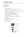
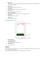
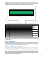
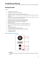
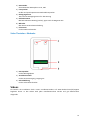
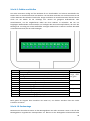
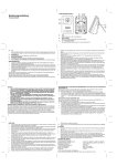
Video Door Station D10x Series Video Türstation D10x Serie Installation manual Pages 1-8 Installationsanleitung Seiten 10-18 Version 1.9, Min. HW 1.01 Installation manual You can always find the www.doorbird.com/support most up-to-date version of the installation manual on Components Contents 1x DoorBird Vdeo Door Station 1x Power supply unit (mains adaptor) with four country-specific adaptors 1x Cable with plug for the power supply (black, red) 1x Cable with plug and RJ45 jack for the network cable (white-orange, orange, white-green, green) 1x Cable with plug for the network cable (white-orange, orange, white-green, green), alternatively to the cable with plug and RJ45 jack 1x Cable with plug for the electric door opener (purple, purple) 1x Cable with plug for the electric door chime (blue, blue) 1x Cable with plug for the door-opening button (yellow, yellow) Several crimp connectors 4x Phillips countersunk head screws for the wall mounting plate, long 4x Phillips countersunk head screws for the wall mounting plate, short 4x Dowels 1x Safety screw 1x Screwing-tool for the safety screw 1x Wall mounting plate with sealing ring (installation on wall surface) 1x Installation manual 1x Quick start guide Video door station - front 1 1) Night vision Extra bright infra-red LEDs, effective during the hours of darkness (infra-red light invisible to the human eye, 850nm) 2) HDTV video Ultra wide-angle hemispheric lens, 180° 3) Loudspeaker Large-sized and speech enhanced broadband speaker 4) Motion sensor 180° Infrared motion sensor for alarms 5) Stainless-Steel Button With illuminated LED ring (at night), also acts as Diagnostic-LED 6) Microphone With active noise cancellation 7) Light sensor For the night-vision mode Video door station - back 1) Locking positions For the mounting plate 2) Connection terminal For the power supply, door chime, etc. 3) Screw opening For the safety screw Videos Need help with the installation? Be sure to watch our installation videos which can be found on http://www.doorbird.com/support Each individual step of the installation is clearly documented in the videos. 2 Installation All the steps below should be carried out carefully by a competent adult, taking into consideration any applicable safety regulations. Should you have any questions, please contact us or a competent specialist directly. Please ensure that all wires used for the installation are undamaged along their entire length and approved for this type of use. Network speed and network components Please ensure that the upload speed of your Internet connection is at least 0.5 Mbps. You can also carry out a speed test at any time via the DoorBird app. The user experience is only as good as your network speed, network stability and quality of your network components, such as your Internet router and WiFi access points or WiFi repeaters. Please also make sure that your network components are no older than two years old, have been manufactured by a well-known manufacturer, and have the latest firmware installed. Should these requirements not be fulfilled, it may happen, for example that the performance of audio and video is poor or push notifications are delayed or do not arrive on your smartphone or tablet at all. High-speed Internet (via landline): DSL, cable or optical fibre Network: 802.11b/g/n 2.4 GHz or Ethernet, with DHCP Step 1: Switching off power Switch off the power to all wires leading to the assembly location, i.e. the door chime, electric door opener, power supply unit for the video door station etc.. Step 2: Dismantling the existing doorbell Should there already be a doorbell on the exterior wall of the house, please dismantle it. Step 3: Determining the assembly location The video door station uses an ultra wide-angle hemispheric lens so that even when the person is a minimum distance of 50 cm (19.68 inches) away from the video door station, a low installation height is sufficient. The lens is therefore not mechanically adjustable. The camera lens should be located at an altitude of at least 125 cm (49.22 inches). You may check this prior to the final mounting. Press the mounting plate against the wall at the desired installation site and mark the boreholes with a pencil. Remove the mounting plate again. Ensure that no cables are to be found in the wall behind the boreholes. Step 4: Power supply The video door station can be powered by two simple doorbell wires using the power-supply unit (mains adaptor) supplied with it or via PoE (Power over Ethernet) using a network cable. The video door station can alternatively also be supplied with a DIN-rail power supply unit that you can obtain from us directly. The video door station does not use battery power. The use of a mains power supply permits the transmission and display of on-demand live video at any time and not only if a visitor has pressed the doorbell. Power supply using the power-supply unit (mains adaptor) Two insulated wires are required to power the video door station by plugging it into the mains. These wires are normally already there and are freely accessible once you have removed the previous doorbell. Only use the power supply unit provided along with the video door station, or a DIN-rail power supply unit that you can obtain from us separately, since this has been specially stabilized electrically and is equipped with an integrated audio interference reduction device. Other power supply units may destroy the video door station or cause poor transmission quality. The warranty automatically expires if you use a different power supply unit. The power supply unit is plugged into 3 a wall socket inside your house, usually where the two wires from your previous doorbell come out of the wall in the interior of the house. Do not plug the power supply unit into the wall socket yet. Connect the power supply unit inside the house with the crimp connector provided and the two wires that you would like to use to power the device. Power supply via PoE (as an alternative) To power the video door station via a PoE switch (e.g. D-Link DGS-1008P) or PoE injector (e.g. TP-Link TL-PoE150S) in accordance with the PoE standard IEEE 802.3af Mode A, the four wires bearing the numbers 1, 2, 3 and 6 of a Cat.5 cable or better are to be used. A Cat.5 cable or better must be used as network signals can only be transmitted over completely insulated, shielded and twisted cables. If you use PoE as a source of power, the WiFi interface of the video door station is automatically inactive, and the four wires for PoE then simultaneously form the data link. The video door station won’t start if your PoE Switch or PoE injector does not support the PoE Standard IEEE 802.3af Mode A (see Diagnostic-LED and Diagnostic-Sounds). 1. Disconnect the PoE switch or PoE injector from the power grid. 2. Place the network cable in the installation site of the video door station. Do not combine the power supply from the power supply unit (mains adaptor) with the power supply via PoE. Step 5: Further connections (optional) If desired, connect additional wires to the installation site of the video door station. The wires or connection options mentioned in this section are optional. Connecting the unit to a network You can connect the video door station to your existing network via WiFi, or alternatively use a network cable (Ethernet). For reasons of network stability, we principally recommend using a network cable, as WiFi is sensitive to interference (range, house walls acting as shields, reliability of performance, third party WiFi networks, wireless transmitters causing interference in the area, etc.). Be sure to use four insulated, shielded and twisted wires of a network cable in accordance with the Cat.5 standard or better. The video door station can be powered by PoE or using the power supply unit provided. If you use PoE as a source of power, the WiFi interface of the video door station remains inactive. Use only four wires (1, 2, 3 and 6) of a network cable that meets the Cat.5 standard or a better one. The other four wires of the network cable (4, 5, 7 and 8) are not required. Connect the network cable in the house to your Internet router or to your PoE switch or PoE injector that is connected to your Internet router. Electric door openers The video door station has a zero-potential relay contact for a Two insulated wires. standardised electric door, gate or garage opener (two wires). There is the possibility of switching on all electric door openers that work at a maximum power of 1A in the voltage range of up to 24V (AC/DC). The video door station does not provide its own power supply for the electric door opener. This is provided through the separate power supply of the electric door opener. You can learn more about the installation of the power supply from the instruction manual or technical specifications of 4 your door opener. Should you have any questions about this, please contact the manufacturer of your door opener. You can find compatible electric door opener and a sample wiring diagram at www.doorbird.com/support Conventional electric door chime If someone rings your video door station, you will immediately receive a Two insulated wires. push notification with sound/vibration on your smartphone or tablet. In addition the video door station comes with a zero-potential relay contact for connecting a conventional electric door chime inside the building. The relay contact can be used to activate the separate operating voltage of the door chime or the door chime via its trigger input. If the operating voltage of the door chime is activated, it should not be greater than 24V (AC/DC). The power consumption should not exceed 1A. The video door station does not provide its own power supply for the door chime. This is provided through the separate power supply of your conventional door chime. Should you have any questions, please contact the manufacturer of your door chime. You can find compatible door chimes and a sample wiring diagram at www.doorbird.com/support Conventional door opener button If an electric door opener is connected to the video door station, the Two insulated wires. door opener can be opened by App and also be directly controlled via a zero-potential button to be found in the interior of the building, i.e. a door opening button. In addition, the door opener button is to be connected to the connection terminal provided. You can find compatible door opener buttons and a sample wiring diagram on www.doorbird.com/support Step 6: Dowels If the exterior wall of the house is not made of wood, you should drill four holes 5 mm in diameter in the wall and then place the dowels provided into the boreholes. If the exterior wall of the house is made of wood, you will usually not require any dowels. There are special dowels for assembling the video door station on an insulating wall, e.g. Fischer insulating dowels. Please check with your insulating material manufacturer regarding which dowels they recommend. Step 7: Attach the mounting plate Put the wires that you would like to connect to the video door station through the opening in the mounting plate provided. Position the mounting plate against the exterior wall of the house and use the screws provided to position it in the dowels or on the wall. The mounting plate for the video door station has been designed in such a way that it can also be installed on uneven walls, so it is not completely flat. The partially greater clearances at the back also serve to stabilize temperature and moisture levels. Step 8: Preparing the wires Remove about 5 mm of insulation material at the end of the wires that you would like to connect to the video door station. Step 9: Connecting the wires It is possible to connect the video door station conveniently and safely via a connection terminal with jacks on the reverse of the video door station. The individual contacts on the connection terminal are labelled on the reverse of the casing. Some connectors on the connection terminal may come provided by us with cable. Please use appropriate crimp connectors or terminal strips to connect the 5 supplied cables with your wires. The accompanying crimp connectors are weatherproof and are equipped with heat-shrink tubing which can be sealed after assembly by, for example, carefully using a heat gun. Please remove any cables on the connection terminal that you do not need. Connector T+ TR+ RO1 O2 C1 C2 B1 B2 VV+ Description White and orange network cable wire (Number 1, Transmit Data +) Orange network cable wire (Number 2, Transmit Data -) White and green network cable wire (Number 3, Receive Data +) Green network cable wire (Number 6, Receive Data -) Electric door opener (zero potential) Electric door opener (zero potential) Electric door chime (zero potential) Electric door chime (zero potential) Door-opening button (zero potential) Door-opening button (zero potential) Power supply, negative pole (-) Power supply, positive pole (+) Wire White-orange, orange, white-green, green Purple, purple Blue, blue Yellow, yellow Black, red Please take care when connecting the wires. Connecting the wires the wrong way may destroy the video door station. Step 10: Final assembly Mount the video door station on the mounting plate. The video door station will click into the locking positions intended for the mounting plate. Use the accompanying safety screw with the appropriate tool to fix the video door station to the underside of the mounting plate. Step 11: Activating the video door station Switch on the power to the wires leading to the assembly location again. You can see whether you have connected the power supply properly from the Diagnostic LED (it lights up once the power has been connected correctly for up to five minutes and continuously in night-vision mode). The video door station is ready for operation (booting up process, any software updates, etc.) once it has emitted a short diagnosis sound from the integrated loudspeaker. This may last for up to 5 minutes. Should you not hear a beep, please check the power supply. Please also check whether you have used a wall-plug power-supply and not PoE and whether you have connected the positive pole and negative pole to the video door station correctly. 6 7 Step 12: Downloading and installing the app Download the "DoorBird" app by Bird Home Automation onto your mobile device from the Apple app store or Google Play store. You can always find the most up-to-date version of the App manual on www.doorbird.com/support If you use WiFi for connecting the video door station to your Internet router, first go to "Settings > WiFi Setup" and follow the instructions. If you have finished the WiFi set-up or have connected the video door station to your Internet router by means of a network cable, go to "Settings > Add device" and click on the QR code icon in the "User" field. Scan the user QR code found on the "Digital Passport" that accompanies the video door station. If you have problems adding the video door station to the App please check if the video door station is online ( www.doorbird.com/checkonline ). If the video door station is not online, please check the WiFi or network cable connection again. Since Apple uses very high quality microphones, loudspeakers and digital audio components that are perfectly in tune with one another, the voice quality with an iPhone or iPad is usually noticeably better than with an Android smartphone or Android tablet. Diagnostic-LED This LED light is only lit up for five minutes after the video door station has been supplied with power (and continuously at night). It lights up as soon as the video door station is supplied with power. Illuminated: Device is powered Diagnostic-sounds After around two to five minutes, the video door station emits brief diagnostic sounds after it has been connected to the power grid. 1x diagnostic sound: The video door station is connected to the Internet 2x diagnostic sounds: The video door station is able to communicate with the router, but cannot access the Internet 3x diagnostic sounds: The video door station has no connection to the network 8 Legal notes General remarks 1. DoorBird is a registered trademark of Bird Home Automation GmbH. 2. Apple, the Apple logo, Mac, Mac OS, Macintosh, iPad, Multi-Touch, iOS, iPhone and iPod touch are trademarks of Apple Inc. 3. Google, Android and Google Play are trademarks of Google, Inc. 4. All other company and product names may be trademarks of the respective companies with which they are associated. 5. We reserve the right to make changes to our products in the interests of technical advancement. The products shown may also look different from the products supplied based on ongoing enhancement. 6. Reproducing or using texts, illustrations and photos from this instruction manual in any media – even if only in the form of excerpts – shall only be permitted with our express written consent. 7. The design of this manual is subject to copyright protection. We do not accept any liability for any errors or any erroneous content or printing errors (even in the case of technical specifications or within graphics and technical sketches). Data privacy and data security 1. For maximum security, the device uses the same encryption technologies as are used in online banking. For your security, no port forwarding or DynDNS is usedeither. 2. The data centre for remote access over the Internet by means of an app is located in the EU and is operated in line with the most stringent security standards. 3. Video door station: In many countries video and voice signal may only be transmitted once a visitor has rung the bell (this feature is available due to data privacy considerations, and is configurable in the app). 4. Please carry out the mounting in such a way that the detection range of the camera limits the device exclusively to the immediate entrance area. 5. The device comes with an integrated visitor history. You can activate/deactivate this function as required (this feature being available due to data privacy considerations). If this function is enabled, up to 20 visitors are archived right inside the electronics of the device, complete with a picture, date and time. Use this function in accordance with the relevant country-specific statutory regulations applicable at the installation site (notification obligation/archival). 6. If necessary, inform visitors that the device has been installed, in a suitable place and in a suitable form. Product Liability Act 1. All products covered by this instruction manual may only be used for the purpose specified. When in doubt, consult a qualified specialist or our support team. 7. If necessary, inform visitors that a motion sensor has been installed in a suitable place and in a suitable form. The motion sensor can, if necessary, be switched off via the app. 2. Products that are supplied with voltage (in particular 110-240V mains voltage) need to be disconnected from the power supply prior to opening them or connecting cables. 8. Please observe any relevant country-specific statutory regulations concerning the use of surveillance components and security surveillance applicable at the installation site. 3. Any losses or consequential damage caused by intervention or changes made to our products or improper handling are excluded from liability. The same applies to improper storage or external effects. Publisher Bird Home Automation GmbH Joachimsthaler Str. 12 10719 Berlin Germany 4. When dealing with 110-240V mains voltage or with mains-operated or battery-operated products, the applicable guidelines are to be observed, e.g. guidelines on adhering to the electromagnetic compatibility; or the low-voltage directive. The respective work should only be carried out by a qualified specialist. Web: www.doorbird.com Email: [email protected] 5. Our products are in compliance with all technical guidelines and telecommunications regulations applicable in Germany, the EU and the USA. 9 Video Door Station D10x Series Video Türstation D10x Serie Installation manual Pages 1-8 Installationsanleitung Seiten 10-18 Version 1.9, Min. HW 1.01 Installationsanleitung Die stets aktuelle Version der Installationsanleitung finden Sie unter www.doorbird.com/de/support Komponenten Inhalt 1x DoorBird Video Türstation 1x Steckernetzteil mit vier Landesadaptern 1x Kabel mit Stecker für die Stromversorgung (schwarz, rot) 1x Kabel mit Stecker und RJ45 Buchse für das Netzwerkkabel (weiß-orange, orange, weißgrün, grün) 1x Kabel mit Stecker für das Netzwerkkabel (weiß-orange, orange, weiß-grün, grün), als Alternative zum Kabel mit Stecker und RJ45 Buchse 1x Kabel mit Stecker für den elektrischen Türöffner (lila, lila) 1x Kabel mit Stecker für den elektrischen Türgong (blau, blau) 1x Kabel mit Stecker für den Türöffnertaster (gelb, gelb) Einige Stoßverbinder 4x Kreuzschlitz-Senkkopfschraube für die Wandmontageplatte, lang 4x Kreuzschlitz-Senkkopfschraube für die Wandmontageplatte, kurz 4x Dübel 1x Sicherheitsschraube 1x Schraub-Tool für die Sicherheitsschraube 1x Wandmontageplatte mit Dichtungsring (Aufputzmontage) 1x Installationsanleitung 1x Quickstartanleitung Video Türstation - Vorderseite 1) Nachtsicht Superhelle Infrarot-LEDs, sind im Dunklen aktiv (für Menschen unsichtbares Infrarotlicht, 850nm) 10 2) HDTV Video Ultraweitwinkel Hemispheric Linse, 180° 3) Lautsprecher Großer und sprachoptimierter Breitbandlautsprecher 4) Bewegungssensor 180° Infrarot Bewegungssensor für Alarmierung 5) Edelstahl Button Mit beleuchtetem LED Ring (nachts), agiert auch als Diagnose-LED 6) Mikrofon Mit aktiver Geräuschunterdrückung 7) Lichtsensor Für den Nachtsichtmodus Video Türstation - Rückseite 1) Einrastpunkte Für die Montageplatte 2) Anschlussterminal Für die Stromversorgung, Türgong etc. 3) Schrauböffnung Für die Sicherheitsschraube Videos Sie können die Installation durch unsere Installationsvideos auf www.doorbird.com/de/support begleiten lassen. In den Videos wird jeder Installationsschritt einzeln und gut dokumentiert dargestellt. 11 Installation Alle folgenden Schritte sollten von einem fachkundigen Erwachsenen sorgsam und unter Berücksichtigung sämtlicher geltender Schutzvorschriften durchgeführt werden. Sollten Sie Fragen haben, wenden Sie sich bitte direkt an uns oder einen kompetenten Fachmann. Achten Sie darauf, dass alle Drähte, die Sie für die Installation verwenden, über die gesamte Länge unbeschädigt und für die Verwendungsart zugelassen sind. Netzwerkgeschwindigkeit und Netzwerkkomponenten Stellen Sie sicher, dass Ihre Internetverbindung über mindestens 0,5 Mbit/s Uploadgeschwindigkeit verfügt. Sie können über die DoorBird App jederzeit auch einen Geschwindigkeitstest durchführen. Das Nutzererlebnis ist nur so gut wie Ihre Netzwerkgeschwindigkeit, Netzwerkstabilität und Qualität Ihrer Netzwerkkomponenten, wie z.B. Ihr Internetrouter und W-LAN Access Points oder W-LAN Repeater. Stellen Sie sicher, dass auch Ihre Netzwerkkomponenten nicht älter als 2 Jahre sind, von einem namhaften Hersteller gefertigt wurden und über die neuste Firmware verfügen. Sind diese Voraussetzungen nicht erfüllt, kann es z.B. dazu kommen, dass Audio- und Videoverbindungen schlecht sind oder Push-Nachrichten verzögert oder gar nicht auf Ihrem Smartphone oder Tablet ankommen. High Speed Internet (Festnetz): DSL, Kabel oder Glasfaser Netzwerk: 802.11b/g/n 2.4GHz oder Ethernet Netzwerk, mit DHCP Schritt 1: Strom abschalten Schalten Sie den Strom sämtlicher zum Montageort führenden Leitungen ab, d.h. z.B. Türgong, elektrischer Türöffner, Netzteil der Video Türstation etc. Schritt 2: Demontage der bestehenden Türklingel Montieren Sie, falls an der Hauswand bereits vorhanden, die bestehende Türklingel ab. Schritt 3: Montageort festlegen Die Video Türstation verwendet eine Ultraweitwinkel Hemispheric Linse, so dass selbst bei einem minimalen Abstand der Person von 50 cm zur Video Türstation eine geringe Montagehöhe ausreicht. Daher ist das Objektiv auch mechanisch nicht verstellbar. Die Kameralinse sollte sich auf einer Höhe von mindestens 125cm befinden. Sie sollten die korrekte Höhe vor der endgültigen Montage testen. Drücken Sie die Montageplatte am gewünschten Installationsort gegen die Hauswand und markieren Sie mit einem Stift die Bohrlöcher. Entfernen Sie die Montageplatte wieder. Stellen Sie sicher, dass sich hinter den Bohrlöchern keine Leitungen in der Hauswand befinden. Schritt 4: Stromversorgung Die Video Türstation kann mit dem mitgelieferten Steckernetzteil über zwei einfache Klingeldrähte oder per PoE (Power over Ethernet) über ein Netzwerkkabel mit Strom versorgt werden. Optional kann die Video Türstation auch mit einem Hutschienennetzteil, das Sie direkt von uns beziehen können, mit Strom versorgt werden. Die Video Türstation hat keine Batterie als Stromversorgung. Eine Netzstromversorgung erlaubt Ondemand live Video, jederzeit, und nicht nur, wenn ein Besucher die Türklingel betätigt hat. Stromversorgung per Steckernetzteil 12 Zur Stromversorgung der Video Türstation per Steckernetzteil werden zwei isolierte Drähte benötigt. Diese Drähte sind im Normalfall bereits vorhanden und frei, wenn Sie die bestehende Türklingel abmontiert haben. Verwenden Sie ausschließlich das mitgelieferte Steckernetzteil oder bei uns separat erhältliche Hutschienennetzteil, da diese speziell stabilisiert und mit einer integrierten Audio Störungsunterdrückung ausgestattet sind. Andere Netzteile können die Video Türstation zerstören und schlechte Übertragungsqualität verursachen. Durch Verwenden eines anderen Netzteils erlischt automatisch die Gewährleistung. Das Steckernetzteil wird im Innenbereich Ihres Hauses, üblicherweise dort, wo die zwei Drähte Ihrer vorherigen Türklingel im Hausinneren aus der Wand kommen, in eine Wandsteckdose gesteckt. Stecken Sie das Steckernetzteil noch nicht in die Wandsteckdose. Verbinden Sie das Steckernetzteil im Hausinneren mit den mitgelieferten Stoßverbinder mit den zwei Drähten, die Sie für die Stromversorgung nutzen möchten. Stromversorgung per PoE (alternativ!) Zur Stromversorgung der Video Türstation per PoE Switch (z.B. D-Link DGS-1008P) oder PoE Injektor (z.B. TP-Link TL-PoE150S) nach PoE Standard IEEE 802.3af Mode A werden die vier Drähte mit den Nummern 1, 2, 3 und 6 eines Cat.5 Kabels oder besser benutzt. Es muss zwingend ein Cat.5 Kabel oder besser zum Einsatz kommen, da Netzwerksignale nur über vollständig isolierte, abgeschirmte und verdrillte Kabel übertragen werden können. Wenn Sie PoE als Stromversorgung nutzen, ist die W-LAN Schnittstelle der Video Türstation automatisch inaktiv, die vier Drähte für PoE sind dann gleichzeitig die Datenleitung. Sollte Ihr PoE Switch oder PoE Injektor keinen PoE Standard IEEE 802.3af Mode A unterstützen, wird die Video Türstation nicht starten (siehe Diagnose-LED und Diagnose-Töne). 1. Trennen Sie den vorgesehenen PoE Switch oder PoE Injektor vom Stromnetz. 2. Führen Sie das Netzwerkkabel zum Montageort der Video Türstation. Kombinieren Sie die Stromversorgung per Steckernetzteil nicht mit der Stromversorgung per PoE. Schritt 5: Weitere Anschlüsse (optional!) Führen Sie, wenn gewünscht, weitere Drähte zum Montageort der Video Türstation. Die in diesem Abschnitt genannten Drähte bzw. Anschlussmöglichkeiten sind optional. Netzwerkverbindung Sie können die Video Türstation per W-LAN oder alternativ per Netzwerkkabel (Ethernet) mit Ihrem vorhandenen Netzwerk verbinden. Aus Stabilitätsgründen empfehlen wir grundsätzlich ein Netzwerkkabel zu nutzen, da W-LAN störempfindlich ist (Reichweite, abschirmende Hauswände, Zuverlässigkeit, fremde W-LAN Netze, störende Funksender in der Nähe und vieles mehr). Vier isolierte, abgeschirmte und verdrillte Drähte eines Netzwerkkabels nach Cat.5 Standard oder besser. Die Video Türstation kann über POE oder dem mitgelieferten Steckernetzteil mit Strom versorgt werden. Wenn Sie POE als Stromversorgung nutzen, ist die W-LAN Schnittstelle der Video Türstation inaktiv. Verwenden Sie ausschließlich vier Drähte (1, 2, 3, 6) eines Netzwerkkabels nach Cat.5 Standard oder besser. Die anderen vier Drähte des Netzwerkkabels (4, 5, 7, 8) werden nicht benötigt und auch nicht an die Video Türstation angeschlossen. 13 Schließen Sie das Netzwerkkabel im Haus an Ihren Internetrouter an bzw. an Ihren PoE Switch oder PoE Injektor, der mit Ihrem Internetrouter verbunden ist. Elektrische Türöffner Die Video Türstation verfügt über einen potentialfreien Relaiskontakt für Zwei isolierte Drähte. standardisierte elektrische Tür-, Tor- oder Garagenöffner (zwei Drähte). Es besteht die Möglichkeit, alle elektrischen Türöffner anzuschalten, die im Spannungsbereich bis 24V (AC/DC) bei einem max. Strom von 1A arbeiten. Die Video Türstation liefert keine Spannungsversorgung, dies erfolgt durch die separate Spannungsversorgung des elektrischen Türöffners. Die Spannungsversorgung können Sie der Anleitung bzw. den technischen Daten Ihres Türöffners entnehmen. Bei Fragen hierzu kontaktieren Sie bitte den Hersteller Ihres Türöffners. Beispiele für kompatible elektrische Türöffner und einen beispielhaften Anschlussplan finden Sie unter www.doorbird.com/de/support Herkömmlicher elektrischer Türgong Wenn jemand bei Ihnen an der Video Türstation klingelt, erhalten Sie Zwei isolierte Drähte. umgehend eine Push-Nachricht mit Ton / Vibration auf Ihrem Smartphone / Tablet. Die Video Türstation verfügt zusätzlich für den Anschluss eines herkömmlichen elektrischen Türgongs im Innenbereich über einen potentialfreien Relaiskontakt. Der Relaiskontakt kann dazu verwendet werden, die separate Betriebsspannung des Türgongs zu schalten oder den Türgong über dessen Triggereingang zu aktivieren. Wenn die Betriebsspannung des Türgongs geschaltet werden soll, darf diese nicht größer als 24V (AC/DC) sein. Die Stromaufnahme darf max. 1A betragen. Die Video Türstation liefert keine Spannungsversorgung, dies erfolgt durch die separate Spannungsversorgung ihres herkömmlichen Türgongs. Bei Fragen hierzu kontaktieren Sie bitte den Hersteller Ihres Türgongs. Beispiele für kompatible Türgongs und einen beispielhaften Anschlussplan finden Sie unter www.doorbird.com/de/support Herkömmliche Türöffnertaster Wenn an der Video Türstation ein elektrischer Türöffner angeschlossen Zwei isolierte Drähte. ist, kann der Türöffner über die App und auch direkt über eine im Innenbereich befindliche potentialfreie Taste oder Türöffnertaste, angesteuert werden. Dazu ist die Türöffnertaste an die dafür vorgesehenen Klemmen am Anschlussterminal anzuschließen. Beispiele für kompatible Türöffnertaster und einen beispielhaften Anschlussplan finden Sie unter www.doorbird.com/de/support Schritt 6: Dübel Wenn es sich bei dem Material der Hauswand nicht um Holz handelt, bohren Sie vier Löcher mit einem Bohrer mit 5 mm Durchmesser in die Hauswand und stecken Sie dann die mitgelieferten Dübel in die Bohrlöcher. Wenn es sich bei der Hauswand um Holz handelt, benötigen Sie im Normalfall keine Dübel. Für die Montage der Video Türstation an einer Wärmeschutzwand gibt es spezielle Dübel, z.B. Fischer Dämmstoffdübel. Bitte klären Sie mit Ihrem Dämmstoffhersteller, welche Dübel von diesem empfohlen werden. 14 Schritt 7: Montageplatte anschrauben Führen Sie die Drähte, die Sie an die Video Türstation anschließen möchten, durch die dafür vorgesehene Öffnung in der Montageplatte. Drücken Sie die Montageplatte gegen die Hauswand und drehen Sie die mitgelieferten Schrauben in die Dübel bzw. in die Hauswand. Die Video Türstation bzw. Montageplatte wurden so entwickelt, dass diese auch an unebenen Wänden montiert werden kann und ist daher nicht ganz plan. Die rückseitigen teils größer dimensionieren Spaltmaße dienen u.a. dem Temperatur- und Feuchtigkeitsausgleich. Schritt 8: Drähte vorbereiten Entfernen Sie etwa 5mm der Isolierung am Ende der Drähte, die Sie an die Video Türstation anschließen möchten. 15 Schritt 9: Drähte anschließen Die Video Türstation verfügt auf der Rückseite für ein komfortables und sicheres Anschließen der Drähte über ein Anschlussterminal mit Buchsen. Die einzelnen Kontakte am Anschlussterminal sind auf der Rückseite des Gehäuses beschriftet. Einige Anschlüsse am Anschlussterminal können bereits durch uns mit Kabeln für Sie vorbelegt sein. Nutzen Sie geeignete Stoßverbinder oder Lüsterklemmen, um die mitgelieferten Kabel mit Ihren Drähten zu verbinden. Die von uns beigelegten Stoßverbinder sind wetterfest und verfügen über einen Schrumpfschlauch, der nach der Montage z.B. vorsichtig mit einem Heißluftfön versiegelt werden kann. Entfernen Sie bitte die Kabel am Anschlussterminal, die Sie nicht benötigen. Anschluss T+ TR+ RO1 O2 C1 C2 B1 B2 VV+ Beschreibung Weiß-oranger Draht des Netzwerkkabels (Nummer 1, Transmit Data +) Oranger Draht des Netzwerkkabels (Nummer 2, Transmit Data -) Weiß-grüner Draht des Netzwerkkabels (Nummer 3, Receive Data +) Grüner Draht des Netzwerkkabels (Nummer 6, Receive Data -) Elektrischer Türöffner (potentialfrei) Elektrischer Türöffner (potentialfrei) Elektrischer Türgong (potentialfrei) Elektrischer Türgong (potentialfrei) Türöffnertaster (potentialfrei) Türöffnertaster (potentialfrei) Netzteil Stromversorgung Minuspol (-) Netzteil Stromversorgung Pluspol (+) Draht Weiß-orange, orange, weißgrün, grün Lila, lila Blau, blau Gelb, gelb Schwarz, rot Bitte gehen Sie sorgsam beim Anschluss der Kabel vor, ein falscher Anschluss kann die Video Türstation zerstören. Schritt 10: Endmontage Montieren Sie die Video Türstation an der Montageplatte. Die Video Türstation rastet an den für die Montageplatte vorgesehenen Einrastpunkten ein. Nutzen Sie die beiliegende Sicherheitsschraube 16 und das dazu passende Schraub-Tool, um die Video Türstation an der Unterseite mit der Montageplatte zu fixieren. Schritt 11: Inbetriebnahme Schalten Sie den Strom der zum Montageort führenden Leitungen wieder an. Ob Sie die Stromversorgung richtig angeschlossen haben, sehen Sie anhand der Diagnose-LED (leuchtet, sobald man den Strom korrekt angeschlossen hat, bis zu fünf Minuten, und permanent nachts). Die Video Türstation ist betriebsbereit (Bootvorgang, etwaige Softwareupdates etc.), sobald diese einen kurzen Diagnose-Ton aus dem integrierten Lautsprecher ausgegeben hat. Dies kann bis zu 5 Minuten dauern. Sollten Sie keinen Piepton hören, prüfen Sie bitte die Stromversorgung und ob Sie, wenn Sie ein Steckernetzteil und nicht PoE verwendet haben, den Pluspol und Minuspol korrekt an die Video Türstation angeschlossen haben. Schritt 12: Download und Installation der App Laden Sie sich die App "DoorBird" von Bird Home Automation aus dem Apple App Store bzw. Google Play Store auf Ihr mobiles Endgerät. Die stets aktuelle Version der App Bedienungsanleitung finden Sie unter www.doorbird.com/de/support Wenn Sie für die Verbindung der Video Türstation zu Ihrem Internetrouter W-LAN verwenden, gehen Sie zuerst auf DoorBird App "Einstellungen > W-LAN Setup" und folgen Sie den Anweisungen. Wenn Sie das W-LAN Setup abgeschlossen haben oder die Video Türstation per Netzwerkkabel mit Ihrem Internetrouter verbunden haben, gehen Sie auf DoorBird App "Einstellungen > Gerät hinzufügen" und klicken Sie auf das QR-Code Symbol im Feld "Benutzer". Scannen Sie den Benutzer QR-Code auf dem der Video Türstation beiliegenden "Digital Passport". Falls Sie Probleme beim Hinzufügen der Video Türstation zur App haben, prüfen Sie bitte, ob die Video Türstation online ist ( www.doorbird.com/de/checkonline ). Sollte diese nicht online sein, prüfen Sie bitte die W-LAN bzw. Netzwerkkabelverbindung der Video Türstation erneut. Da Apple sehr hochwertige und perfekt aufeinander abgestimmte Mikrofone, Lautsprecher und digitale Audiokomponenten verwendet, ist die Sprachqualität mit einem iPhone oder iPad im Normalfall deutlich besser als mit einem Android Smartphone oder Android Tablet Diagnose-LED Diese LED ist nur fünf Minuten lang beleuchtet, nachdem man die Video Türstation mit Strom versorgt hat (und permanent nachts). Sie leuchtet, sobald man die Video Türstation mit Strom versorgt. Beleuchtet: Gerät ist mit Strom versorgt Diagnose-Töne Die Video Türstation gibt nach etwa zwei bis fünf Minuten kurze Töne zur Diagnose aus, nachdem man sie mit dem Stromnetz verbunden hat. 1x Diagnose-Ton: Die Video Türstation ist mit dem Internet verbunden 2x Diagnose-Ton: Die Video Türstation kann zwar den Router erreichen, nicht aber das Internet 3x Diagnose-Ton: Die Video Türstation hat keine Netzwerkverbindung 17 18 Rechtliche Hinweise Allgemeines 1. DoorBird ist ein registriertes Warenzeichen der Bird Home Automation GmbH. 2. Apple, das Apple Logo, Mac, Mac OS, Macintosh, iPad, Multi-Touch, iOS, iPhone und iPod touch sind Warenzeichen von Apple Inc. 3. Google, Android und Google Play sind Warenzeichen von Google, Inc. 4. Alle anderen Firmen- und Produktnamen können Warenzeichen der jeweiligen Firmen sein, mit denen sie in Verbindung gebracht werden. 5. Änderungen an unseren Produkten, die dem technischen Fortschritt dienen, behalten wir uns vor. Die abgebildeten Produkte können im Zuge der ständigen Weiterentwicklung auch optisch von den ausgelieferten Produkten abweichen. 6. Abdrucke oder Übernahme von Texten, Abbildungen und Fotos in beliebigen Medien aus dieser Anleitung – auch auszugsweise – sind nur mit unserer ausdrücklichen schriftlichen Genehmigung gestattet. 7. Die Gestaltung dieser Anleitung unterliegt dem Urheberschutz. Für eventuelle Irrtümer, sowie inhaltlichebzw. Druckfehler (auch bei technischen Daten oder innerhalb von Grafiken und technischen Skizzen) übernehmen wir keine Haftung. Produkthaftungsgesetz 1. Alle Produkte aus dieser Anleitung dürfen nur für den angegebenen Zweck verwendet werden. Wenn Zweifel bestehen, muss dies mit einem kompetenten Fachmann oder unserem Support abgeklärt werden. 2. Produkte, die spannungsversorgt sind (insbesondere 110240V Netzspannung), müssen vor dem Öffnen oder Anschließen von Leitungen von der Spannungsversorgung getrennt sein. 3. Schäden und Folgeschäden, die durch Eingriffe oder Änderungen an unseren Produkten sowie unsachgemäßer Behandlung verursacht werden, sind von der Haftung ausgeschlossen. Gleiches gilt für eine unsachgemäße Lagerung oder Fremdeinwirkungen. 4. Beim Umgang mit 110-240V Netzspannung oder mit am Netz oder mit Batterie betriebenen Produkten, sind die einschlägigen Richtlinien zu beachten, z.B. Richtlinien zur Einhaltung der Elektromagnetischen Verträglichkeit oder Niederspannungsrichtlinie. Entsprechende Arbeiten sollten nur von einem Fachmann ausgeführt werden, der damit vertraut ist. Datenschutz und Datensicherheit 1. Für maximale Sicherheit verwendet das Gerät dieselben Verschlüsselungstechnologien wie beim Onlinebanking. Zu Ihrer Sicherheit sind auch keine Portweiterleitungen oder DynDNS im Einsatz. 2. Das Rechenzentrum für den Fernzugriff per App über das Internet steht in der EU und wird nach strengsten Sicherheitsstandards betrieben. 3. Video Türstation: In vielen Ländern darf Videobild und Sprache erst dann übertragen werden, wenn ein Besucher geklingelt hat (Datenschutz, konfigurierbar in der App). 4. Führen Sie die Montage so durch, dass sich der Erfassungsbereich der Kamera ausschließlich auf den unmittelbaren Eingangsbereich beschränkt. 5. Das Gerät verfügt über eine integrierte Besucherhistorie, diese Funktion können Sie bei Bedarf aktivieren/deaktivieren (Datenschutz). Bei aktivierter Funktion werden bis zu 20 Besucher mit Bild, Datum und Uhrzeit direkt im Gerät archiviert. Nutzen Sie diese Funktion gemäß der am Installationsort geltenden relevanten landespezifischen gesetzlichen Regelungen (Hinweispflicht / Archivierung). 6. Weisen Sie bei Erfordernis an geeigneter Stelle und in geeigneter Form auf das Vorhandensein des Geräts hin. 7. Weisen Sie bei Erfordernis an geeigneter Stelle und in geeigneter Form auf das Vorhandensein eines Bewegungsmelders hin. Der Bewegungsmelder kann, falls erforderlich, über die App abgeschaltet werden. 8. Beachten Sie alle am Installationsort geltenden relevanten landespezifischen gesetzlichen Regelungen für den Einsatz von Überwachungskomponenten und Überwachungskameras. Herausgeber Bird Home Automation GmbH Joachimsthaler Str. 12 10719 Berlin Deutschland Web: www.doorbird.com Email: [email protected] Web: www.doorbird.com Email: [email protected] 5. Unsere Produkte entsprechen sämtlichen in Deutschland, der EU und USA geltenden technischen Richtlinien und Telekommunikationsbestimmungen. 19 Space for your notes / Platz für Ihre Notizen www.doorbird.com