1
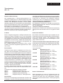
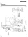
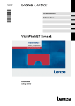
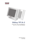
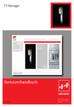
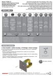
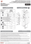
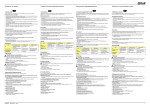
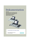
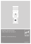
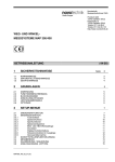
®
SICHERHEIT
UND PRÄZISION
Elektro-Türöffner
Türsteuerungs-Systeme
®
DIN EN ISO 9001
®
D 0006801
BEDIENUNGS-ANLEITUNG
d e u t s c h
Türcode-Anlage
430 - 10
OPERATING INSTRUCTIONS
e n g l i s h
Door Coding System
430 - 10
MODE D'EMPLOI
f r a n ç a i s
Système d'ouverture
de porte par code
d'accès 430 -10
®
SICHERHEIT
UND PRÄZISION
Elektro-Türöffner
Türsteuerungs-Systeme
d e u t s c h
Türcode-Anlage
430 - 10
e n g l i s h
Door Coding System
430 - 10
f r a n ç a i s
Système d'ouverture
de porte par code
d'accès 430 - 10
Inhalt
Allgemeine Beschreibung
Die Tastaturen
Die Türöffner
Externe Türöffner-Taster
Funktionsschalter
Codestellen-Wahlschalter
Einstellung der Türentriegelungs-Zeit
Einstellung der Falschcoderelais-Anzugszeit
Externe Störeinflüsse – Reset-Taste
Technische Daten
Elektroinstallationen
Anschlußpläne
Seite
3
3
3
3
4
4
4
4
5
5
5
12
Contents:
General description
Keypads
Door releases
External door release push-buttons
Function switches
Code digit selection switches
Setting the door unlocking period
Setting the erroneous code relay - reaction period
External noise influences - reset key
Technical specifications
Electrical wiring
Connection diagram
Page
6
6
6
7
7
7
7
7
8
8
8
13
Sommaire :
Description générale
Clavier
Gâche
Boutons-poussoir
Sélecteurs de mode (switch)
Selecteur pour longeur du code
Réglage du temps de déverrouillage
Réglage du temps d’excitation du relais de faux code
Influences perturbatrices externes - Reset
Caractéristiques techniques
Installation électrique
Plan de raccordement
Page
9
9
9
10
10
10
10
10
11
11
11
14
d e u t s c h
Türcodeanlage
430 - 10
Das vollelektronische / mikroprozessorgesteuerte Türcodesystem Modell 430-10 in Einkanal-Ausführung bietet
die Anschlußmöglichkeit für eine Tür (Türöffner) und eine
Tastatur. Das Steuergerät beinhaltet in einem stabilen
Stahlblechgehäuse die Türcodeelektronik und das Netzteil.
Durch eine abschließbare Fronttür ist das Steuergerät vor
Manipulationen unberechtigter Personen geschützt.
Die Tastatur wird üblicherweise im Handbereich der Tür,
und das Steuergerät im geschützten Bereich innerhalb des
Gebäudes, montiert. Der Elektro-Türöffner wird als Gegenstück zum Türschloß in den Türrahmen eingebaut.
3405 RR/3705 RR (Ruhestromfunktion). Es wird grundsätzlich empfohlen, Türöffner mit Rückmeldekontakten (Bestellzusatz RR) zu verwenden. Die elektrische Leitungsverbindung von der Türcodeanlage zum Elektro-Türöffner
muß mit abgeschirmter Installationsleitung erfolgen.
Türöffner mit Arbeitsstromfunktion:
Der Arbeitsstrom-Türöffner z.B. 1405 RR ist mit Spannung
entriegelt. Bei Stromausfall bleibt die Verschlußsicherheit
der Tür gewährleistet.
Türöffner mit Ruhestromfunktion:
Der Ruhestrom-Türöffner z.B. 3405 RR ist ohne Spannung
entriegelt. Bei Stromausfall ist die Tür für jeglichen Zutritt
frei.
Funktion
Sicherheits-Türöffner
Die am Tastgerät eingegebene 4-stellige Codezahl wird in
elektrische Signale umgesetzt und an das Steuergerät
weitergegeben. Hier wird durch Vergleich der Signale mit
der vorgegebenen Codezahl über die Zutrittsberechtigung
entschieden. Ist diese positiv, schaltet das Türöffner-Ausgangsrelais für eine im Steuergerät voreingestellte Zeit
(Türentriegelungszeit), die Tür frei.
Die 4-stellige Codezahl kann jederzeit an den 4 Codeschaltern, die auf der Hauptplatine angeordnet sind, verändert werden.
Bei erhöhten Sicherheitsanforderungen empfiehlt sich der
Einbau der Sicherheits-Türöffner Modell 14105 RR (Arbeitsstrom) oder Modell 341055 RR (Ruhestrom). Diese
Sicherheits- Türöffner haben eine Druckfestigkeit >15 KN
gegen Aufbruchversuche.
Die Tastaturen
Technische Daten
1405 RR
Nennspannung 12 V(Spannungstoleranz 11 - 13 V-)
Stromaufnahme 200 mA, 100% ED
1705 RR
Nennspannung 12 V(Spannungstoleranz 11 - 13 V-)
Stromaufnahme 230 mA, 100% ED
3405 RR
Nennspannung 12 V(Spannungstoleranz 11 - 13 V-)
Stromaufnahme 200 mA, 100% ED
3705 RR
Nennspannung 12 V(Spannungstoleranz 11 - 13 V-)
Stromaufnahme 230 mA, 100% ED
14105 RR
Nennspannung 12 V
(Spannungstoleranz 11 - 13 V-)
Stromaufnahme 400 mA, 100% ED
34105 RR
Nennspannung 12 V(Spannungstoleranz 11 - 13 V-)
Stromaufnahme 470 mA, 100% ED
Allgemeine Beschreibung
Tastaturen werden stets im Handbereich der Türen montiert. Nach dem Abschrauben und Abnehmen der Frontplatte kann man das Tastaturgehäuse bequem installieren.
Das Einführen und Anschließen der 7-adrigen, abgeschirmten Steuerleitung (siehe Anschlußschaltbild), ist jetzt möglich. Beim anschließenden Wiederaufschrauben der Frontplatte, muß bei wassergeschützten Tastaturen darauf geachtet werden, daß die Dichtung nicht beschädigt wird. Als
Tastatursteuerkabel ist mindestens eine 7-adrige, abgeschirmte Leitung erforderlich. Die maximale Leitungslänge
zwischen Tastatur und Steuergerät darf 200 m nicht überschreiten. Von der Türcodeanlage aus müssen sämtliche
Leitungen separat verlegt werden.
Es stehen verschiedene Tastgeräte zur Auswahl. Ihnen
allen ist gemeinsam, daß sie eine 12er Matrixtastatur besitzen.
Im Einzelnen sind folgende Tastaturen lieferbar:
412-12
-Tastgerät-Aufputzausführung,
413-12
-Tastgerät-Aufputz, wassergeschützt,
414-12
-Tastgerät-Unterputzausführung,
415-12
-Tastgerät-Unterputz, wassergeschützt
Die Türöffner
Die mit der Türcodeanlage einzusetzenden Türöffner sind
die Modelle 1405 RR/1705 RR (Arbeitsstromfunktion) und
Türöffner mit Rückmeldekontakten Bestellzusatz „RR“
Automatisches Rücksetzen des Türöffnerrelais bei aufgemachter Tür. Somit ist die anschließend zugemachte Tür
sofort wieder verriegelt.
Externe Türöffnertaster
Mittels bauseitiger bzw. externer Türöffnertaster kann die
Tür in gewohnter Weise von innen geöffnet werden. Der
Türöffner wird dann über die voreingestellte Türentriegelungszeit (Funktionsdrehschalter Türentriegelungszeit)
entriegelt.
3
d e u t s c h
Türcodeanlage
430 - 10
Funktionschalter (Schiebeschalter 1-3)
Schiebeschalter 1: Dauerentriegelung/Kurzzeitentriegelung
Variante A:
Schiebeschalter 1-on- (oben) Kurzzeitentriegelung
(werkseitige Einstellung). Nach Eingabe der richtigen Codezahl, entriegelt der Elektro- Türöffner für
die am Funktionsdrehschalter (Türentriegelungszeit) eingestellte Türentriegelungszeit.
Variante B:
Schiebeschalter 1-off-(unten) Dauerentriegelung.
Durch das Betätigen der Plus-Taste und anschliessendes Eingeben der richtigen Codezahl an der
Tastatur, kann die Tür dauerentriegelt werden.
Somit besteht die Möglichkeit, diese Tür beliebig oft
zu begehen. Zum Wiederverriegeln der Tür muß an
der Tastatur zunächst die Minus-Taste und dann
die Codezahl eingegeben werden. Wird die PlusTaste an der Tastatur nicht betätigt, ist bei Eingabe
der richtigen Codezahl die Grundfunktion (Kurzzeitentriegelung) wirksam.
Schiebeschalter 2: Normalbetrieb/Testbetrieb
Variante A:
Schiebeschalter 2-on-(oben) Normalbetrieb
(werkseitige Einstellung). Wie der Name Normalbetrieb aussagt, sind hierbei die Standardfunktionen
wie in der Beschreibung Kurzzeit- bzw. Dauerentriegelung wirksam.
Variante B:
Schiebeschalter 2-off-(unten) Testbetrieb.
Bei dieser Funktion können die Zifferntafeln des
Tastgerätes sowie die Tastgerätsteuerleitung auf
ordnungsgemäße Funktion überprüft werden. Bei
jeder Ziffernbetätigung am Tastgerät wird das Türöffnerrelais (Elektro-Türöffner) angesteuert.
Die Plus- bzw. Minus-Taste am Tastgerät arbeitet
nach dem gleichen Testmodus, jedoch wird hierbei
der Rückmeldekontakt des Türöffners noch zusätzlich auf Durchgang geprüft (Türstellung für
Testbetrieb-Tür zu).
Sollte ein Elektro- Türöffner ohne Rückmeldekontakt
verwendet werden, wird hierbei die richtige Grundeinstellung des Schiebeschalters 3 geprüft.
Falsche Gerätegrundeinstellung, falscher Anschluß,
sowie defekte Tastgerätsteuerkabel und Funktionsfehler des Türöffnerrückmeldekontaktes können
durch diesen Testmodus lokalisiert werden.
4
Schiebeschalter 3:
Elektro-Türöffner mit Rückmeldekontakt RR/ Elektro-Türöffner ohne Rückmeldekontakt RR
Variante A:
Schiebeschalter 3-on (oben) Anschluß eines
Elektro-Türöffners ohne Rückmeldekontakt RR
Variante B:
Schiebeschalter 3-off (unten) Anschluß eines
Elektro-Türöffners mit Rückmeldekontakt RR
(werkseitige Einstellung)
Einstellung der Türentriegelungszeit
"Funktionsdrehschalter Türentriegelungszeit" Auf der
Anschlußplatine der Türcodeanlage befindet sich ein Drehschalter, der zur Einstellung der Türentriegelungszeit dient.
Diese Einstellung bestimmt die Zeit, in der die Tür geöffnet
werden kann, nachdem die richtige Codezahl eingegeben
wurde.
Raster 1 Teilstrich
= 2 Sek. Türentriegelungszeit
(max. 30 Sek. einstellbar)
Bei Verwendung von Türöffnern mit Rückmeldekontakten
RR (Funktionsschalter, Schiebeschalter auf Stellung 3-off),
wird die Türentriegelungszeit nach einmaliger Begehung
zurückgestellt.
Einstellung der Falschcoderelais-Anzugszeit
”Funktionsdrehschalter Falschcoderelais-Anzugszeit”
Mit der Funktion Falschcodeauswertung wird das Herausfinden der richtigen Codezahl durch ”Probieren” erschwert.
Werden mehr als 5 falsche Codezahlen (20 Ziffern) eingegeben, zieht das Falschcoderelais (potentialfreier Relaiskontakt) für die am Funktionsdrehschalter voreingestellte
Zeit an.
Zusätzlich wird die Tastatur während der Anzugszeit des
Falschcoderelais gesperrt. Die Eingabe der richtigen Codezahl ist erst nach Ablauf der eingestellten Zeit möglich.
Weitere Versuche sind dadurch sinnlos geworden. Der
Funktionsdrehschalter für die Falschcoderelais - Anzugszeit befindet sich auf der Anschlußplatine der Türcodeanlage.
Raster 1 Teilstrich =
6 Sek. Türcoderelais-Anzugszeit
(max.90 Sek. einstellbar)
d e u t s c h
Türcodeanlage
430 - 10
Externe Störeinflüsse - Reset - Taster
Technische Daten:
Trotz interner Schutzmaßnahmen können außergewöhnlich starke Störfelder eine Störung der mikroprozessorgesteuerten Türcodeanlage herbeiführen. Störeinflüsse
können verhindert werden, wenn bei der Installation
folgende Punkte beachtet werden:
Anschlußspannung
230 V WS +10%/-10%
Frequenz
50 - 60 Hz
Leistungsaufnahme
max. 21 W
Betriebsnennspannung
12 V max. Belastbarkeit
600 mA
für externe Verbraucher (z.B. Türöffner)
Schutzart
IP 20
Betriebstemperatur
00 C bis 400 C
– Gerät nicht in unmittelbarer Nähe von
induktiven Verbrauchern montieren
– Separate Leitung für Netzspannungs
versorgung verlegen ( evtl. Netzfilter ).
– Induktive Verbraucher entstören
(Varistor, RC-Glied)
Nach Störungsbeseitigung ist die Neuinbetriebnahme
(Reset) der Türcodeanlage erforderlich. Hierzu muß der
Reset-Taster, der sich auf der Hauptplatine befindet,
gedrückt werden, bis die danebenliegende gelbe LED
kurz aufleuchtet.
Eingänge:
1 Netzanschluß mit Schutzleiter
1 Tastgerät (7-polig)
1 Türöffner mit Rückmeldekontakten
1 Türöffner- Taster
Ausgänge:
1 Elektro- Türöffner (Relais mit potentialfreiem Wechselkontakt)
1 Falschcoderelais (Relais mit potentialfreiem Wechselkontakt)
Alle Relaiskontakte sind mit max. 65 V/2 A belastbar.
®
Elektro-Installation
Geschützter Bereich
(innen)
abgeschirmt
8 max 200 m
430 - 10
~
–
Tastgerät
7
4
1
+
4 abgeschirmt
8
5
2
0
9
6
3
–
2 abgeschirmt
Elektro-Türöffner
Türöffner-Taster
3
230 V / 50 - 60 Hz
2
NYM 3 x 1,5 mm
5
e n g l i s h
Door Coding System
430 - 10
General description
The fully electronic/microprocessor-controlled door coding
system model 430-10 in the single channel version provides
facilities for the connection of one door (door release) and
one keypad. Residing in a robust sheet steel enclosure the
control device comprises the door coding electronics and
the power unit. The control device is protected against
manipulation by unauthorized persons by means of a
lockable front door.
The keypad is usually mounted within hand reach of the
door and the control device in the protected area inside the
building. The electric door release is fitted into the door
frame in the form of a counterpart to the door lock.
Function:
The 4-digit code number entered via the keypad are
converted into electrical signals and passed on to the control
device. There it is decided as to access entitlement by
comparing the signals with the prespecified code number.
If this is positive the door release output relay will switch to
release for a time period (door unlocking period) that has
been preset in the control device.
The 4-digit code number can be altered at any time using
the 4 code switches arranged on the main circuit board.
Keypads
Keypads are always mounted within hand reach of doors.
The keypad enclosure can be conveniently fitted by unscrewing and removing the front panel. Introduction and
connection of the 7-conductor screened control cable (see
connection diagram) is now possible. When the front panel
is subsequently screwed back on, in the case of keypads
protected against water, care must be taken that the seal is
not damaged. Screened cable with a minimum of 7
conductors is required to be used for the keypad control
cable. A lead length between keypad and control device of
200 m may not be exceeded. Outgoing from the door coding
system all leads must be laid separately.
A choice of several different keypad units is available.
Common to all is that they have a 12-key matrix keypad.
In detail the following keypads are available:
412-12
keypad unit
- surface mounted version
413-12
keypad unit
- surface mounted,
protected against water
414-12
keypad unit
- concealed mounting
415-12
keypad unit
- concealed mounting,
protected against water
6
Door releases
The door releases to be utilized together with the door coding
system are the models 1405 RR/1705 RR (energized mode)
and 3405 RR/3705 RR (nonenergized mode). It is recommended fundamentally that the door release be used
together with check-back position indicator contacts (ordering suffix RR). The electrical lead connection between the
door coding system and the electrical door release must be
effected using screened cable.
Door release in energized mode:
The energized mode door release, e.g. 1405 RR, is unlocked
when under voltage. In the event of a power failure the
locking security of the door is guaranteed.
Door release in nonenergized mode:
The nonenergized mode door release, e.g. 3405 RR, is
unlocked when not under voltage. In the event of a power
failure the door provides absolutely free access.
Security door release
In the case of enhanced security requirements it is recommended that security door release model 14105 RR
(energized mode) or 34105 RR (nonenergized mode) be
fitted. These security door releases have a pressure
resistance of > 15 KN to break-in attempts.
Door release with check-back
position indicator contacts,
ordering suffix ...RR
Automatic resetting of the door release relay when the
door is opened. Thus the subsequently closed door is
immediately relocked.
Technical specifications:
1405 RR voltage rating 12 V (voltage tolerance 11 - 13 V)
power consumption 200 mA, continuous duty
1705 RR voltage rating 12 V (voltage tolerance 11 - 13 V)
power consumption 230 mA, continuous duty
3405 RR voltage rating 12 V (voltage tolerance 11 - 13 V)
power consumption 200 mA, continuous duty
3705 RR voltage rating 12 V (voltage tolerance 11 - 13 V)
power consumption 230 mA, continuous duty
14105 RR voltage rating 12 V (voltage tolerance 11 - 13 V)
power consumption 400 mA, continuous duty
34105 RR voltage rating 12 V (voltage tolerance 11 - 13 V)
power consumption 470 mA, continuous duty
e n g l i s h
Door Coding System
430 - 10
External door release keys
The door can be opened in the usual way from internal
rooms by means of door release keys provided on site or
externally. The door release is then unlocked via the preset
door unlocking period (rotary function switch for door
unlocking period).
Function switches (sliding switches 1-3)
Sliding switch 1: continuous unlocking/short period unlocking
Variation A:
Sliding switch 1 -on- (at top) short period
unlocking (setting ex-works). After input of the
correct code number the electric door release
unlocks for the door unlocking period set via the
rotary function switch (door unlocking period).
Variation B:
Sliding switch 1 -off- (at bottom) continuous unlocking .
The door can be continuously unlocked by actuating
the plus key and subsequent entry of the correct
code number via the keypad. The possibility thus
exists of accessing this door with random frequency.
In order to relock the door first of all the minus key
and then the code number have to be entered at the
keypad. If the plus key is not actuated on the keypad
the basic function (short period unlocking) is
effective upon entry of the correct code number.
Sliding switch 2: 1 Normal mode/test mode
Variation A:
Sliding switch 2 -on- (at top) normal mode (setting
ex-works). As the name suggests, in this case the
standard functions are effective as in the description
short period or continuous unlocking.
Variation B:
Sliding switch 2 -off- (at bottom) test mode . With this
function the numeric keys on the keypad and the
keypad control line can be verified as to orderly
functioning. The door release relay (electric door
release) is driven upon each numeral actuation on
the keypad. The plus or minus keys on the keypad
function in test mode in the process, however, the
door release’s check-back position indicator contact
is tested additionally for connection (door position
for test mode - door closed). If an electric door release without check-back position indicator is being
used, the correct basic setting of the sliding switch3
is verified in the process. An erroneous basic setting,
a wrong connection, defective keypad control cable
or functional error of the door release check-back
position indicator contact can be localized by means
of this test mode.
Sliding switch 3: electric door release with check-back
position indicator contact RR
electric door release without check-back position indicator
contact RR
Variation A:
Sliding switch 3 -on (at top) connection of an
electric door release without check-back position
indicator contact RR
Variation B:
Sliding switch 3 -off (at bottom) connection of an
electric door release with check-back position
indicator contact RR (setting ex-works)
Setting of the door unlocking period
"Rotary function switch for door unlocking period". A rotary
switch is located on the connection board of the door coding
system, the purpose of which is the setting of the door
unlocking period. This setting determines the time period
during which the door can be opened after the correct code
number has been entered.
Graduation 1 increment = 2 secs. door unlocking period
(settable to 30 secs. max.)
If door releases with check-back position indicator contacts
RR (function switch, sliding switch in position 3 -off-) are
being used, the door unlocking period is reset after a single
access.
Setting of the erroneous code relay - reaction period
"Rotary function switch erroneous code relay reaction period"
Ascertaining the correct code number by "trial and error" is
made more difficult by the erroneous code evaluation
function. If more than 5 erroneous code numbers (in the
case of a 4-digit code number 20 numbers, in the case of a
6-digit code number 30 numbers) are entered, the erroneous
code relay (zero potential relay contact) reacts for the time
preset via the rotary function switch.
In addition the keypad is disabled during the reaction time
of the erroneous code relay. Entry of the correct code number
is not possible until the preset time period has expired. Further
"attempts" will therefore be pointless. The rotary function
switch for the erroneous code relay reaction time is located
on the connection board of the door coding system.
Graduation 1 increment = 6 secs. door code relay reaction
time (settable to 90 secs. max.)
7
e n g l i s h
Door Coding System
430 - 10
External noise influences - reset key
Technical specifications:
Despite internal proofing measures exceptionally strong
noise fields can bring about a malfunction of the
microprocessor-controlled door coding system. Noise
influences can be prevented if the following points are heeded
during installation:
Connected voltage
Frequency
Power consumption
Operating voltage
Load capacity
230 V AC + 10 % / - 10 %
50 - 60 Hz
21 W max.
12 V
600 mA max. for external power
consumers (e.g. door releases)
Degree of protection
IP 20
Operating temperature 0 °C to 40 °C
– Do not mount the unit in the immediate vicinity of
inductive power consumers.
– Lay a separate line for mains voltage supply
(possibly using a mains filter) .
– Suppress any inductive power consumers
(varistors, RC-sections).
After elimination of the noise, resetting of the door coding
system is necessary. For this purpose the reset key, which
is located on the main board, has to be pressed until the
adjacent yellow LED illuminates briefly.
Inputs:
1 mains connection with earth lead
1 keypad unit (7-pole)
1 door release with check-back position indicator contacts
1 door release push-button
Outputs:
1 electric door release
(relay with zero potential alternating contact)
1 erroneous code relay
(relay with zero potential alternating contact)
All relay contacts can be subjected to a maximum load
of 65 V/2 A.
®
Protected zone
(inside)
Electrical Wiring
keypad unit
8 screened
200 mtrs max.
430 - 10
~
–
4
screened
2
7
4
1
+
8
5
2
0
9
6
3
–
screened
electric door release
door release push-button
3
230 V / 50 - 60 Hz
2
NYM 3 x 1,5 mm
8
f r a n ç a i s
Centrale à clavier digital
430 - 10
Descripton générale
Gâche fonctionnant en courant de travail
La centrale à clavier digital 430-10 est commandée par un
microprocesseur, qui lui permet de gérer l´accès d´une porte
(centrale 1 porte). Autrement dit, elle peut être reliée à une
gâche et â un clavier à touches numériques. Abritée dans
un boîtier métallique robuste, la centrale comprend l’électronique de commande et le bloc d‘alimentation. Une porte
frontale, fermée à clé, la protége contre toute inter- vention
de la part de personnes non autorisées.
La gâche fonctionnant en courant de travail, par ex. 1405
RR, est déverrouillée sous tension, le verrouillage restant
ainsi garanti en cas de rupture de courant.
La centrale est installée généralement dans un endroit
protégé, à l‘intérieur du bâtiment, alors que le clavier à
touches numériques l‘est à proximité immédiate de la porte
dont il doit gérer l‘accès. La gâche électrique adéquate est
montée dans le chambranle.
Fonctionnement
Le coe à 4 chiffres tapés sur le clavier sont convertis en
signaux électriques et transmis au système de commande
qui les compare aux chiffres programmés. Si le code est
identifié, l‘accès est autorisé et le relais de la gâche se
libère pendant une durée enregistrée au préalable dans la
centrale de commande (temps de déverrouillage de la porte).
Le code à 4 chiffres peut être modifié à tout moment sur les
4 interrupteurs de codage qui trouvent sur la platine
principale.
Clavier
Le clavier est à installer à proximité de la porte. Retirer la
plaque frontale pour pouvoir le fixer sans problèmes et mettre
en place le câble de commande à 7 fils avec écran (voir
schéma de connexion). Dans le cas d‘un clavier en version
étanche, veiller à ne pas détériorer le joint au moment de la
remise en place de la plaque frontale. Pour relier le clavier
à la centrale, le minimum requis est un câble à 7 fils avec
écran. Sa longueur ne doit pas excedér 200 m. Chaque
câble quittant la centrale est à poser de facon distincte.
Nous proposons les claviers ci-dessous qui ont tous en
commun une configuration matricielle de 12 touches;
Claviers disponibles:
Clavier 412-12 - version en saillie
Clavier 413-12 - version en saillie et étanche
Clavier 414-12 - version encastrée
Clavier 415-12 - version encastrée et étanche
Gâche
La centrale à clavier digital 430-10 implique l‘utilisation d‘une
gâche parmi les modèles suivants: 1405 RR/1705 RR
(courant de travail) ou bien 3405 RR/3705 RR (courant de
repos). On recommande en principe l‘emploi d‘une gâche
à contact de fond de pêne (suffixe de référance: RR).
Gâche fonctionnant en courant de repos
La gâche fonctionnant en courant de repos, par ex. 3405
RR, est deverrouillée en l‘absence de courant, ce qui signifie
qu‘en cas de rupture de l‘alimentation électrique, la porte
est libérée et peut être franchie à tout moment.
Gâche de sécurité
Lorsqu‘il convient de mettre en place des mesures de
sécurité renforcées, il est préférable d'utiliser une gâche de
sécurité 14105 RR (courant de travail) ou 34105 RR (courant
de repos). Ces gâches peuvent resister aux tentatives
d‘effraction jusqu‘à des forces > 15 kN.
Gâche avec contact de fond de pêne, suffixe de
référence: RR
A l‘ouverture de la porte, le relais de gâche se repositionne
automatiquement de sorte que la porte refermée immédiatement verrouillée en se refermant.
Caractéristiques techniques:
1405 RR
Tension nominal 12 V(tension admise: de 11 V â 13 V)
Consommation de courant: 200 mA
Gâche sous tension permanente
1705 RR
Tension nominal 12 V(tension admise: de 11 V à 13 V)
Consommation de courant: 230 mA
Gâche sous tension permanente
3405 RR
Tension nominal 12 V(tension admise: de 11 V à 13 V)
Consommation de courant: 200 mA
3705 RR
Tension nominal 12 V(tension admise: de 11 V à 13 V)
Consommation de courant: 230 mA
14105 RR
Tension nominal 12 V(tension admise: de 11 V à 13 V)
Consommation de courant: 400 mA
Gâche sous tension permanente
34105 RR
Tension nominal 12 V(tension admise: de 11 V à 13 V)
Consommation de courant: 470 mA
9
f r a n ç a i s
Centrale à clavier digital
430 - 10
Bouton-poussoir
Un boutton poussoir permet d‘ouvrir normalement la porte
de l‘intérieur. La durée de libération de la gâche est alors
fonction du temps de déverrouillage programmé (bouton de
réglage du temps de déverrouillage).
Switch 3
Position ON (en haut): Raccordement d‘une gâche sans
contact de fond de pêne
Position OFF (en bas): Raccordement d‘une gâche avec
contact de fond de pêne (RR)
Réglage du temps de verrouillage
Sélecteurs de mode (switch 1-3)
Switch 1
Position ON ( en haut): Déverrouillage momentané
(réglage à l‘usine)
Si le code correct a éte composé,la
gâche se libère pour la durée
programmée sur le bouton de
réglage ( du temps de déverrouillage de la porte).
Position OFF ( en bas): Déverrouillage permanent
Pour obtenir un déverrouillage
permanent, presser la touche + et
composer le code. La porte peut
alors être franchie à loisir. Pour la
reverrouiller, presser la touche puis recomposer le code.
Switch 2
Position ON (en haut): Mode normal (réglé à l‘usine)
Dans ce qu‘on appelle "mode normal", les fonctions activées sont
les fonctions standards donnés par
le switch 1
Position OFF (en bas): Mode test
Cette fonction permet de côntroler
le fonctionnement des touches du
clavier ainsi que celui du câble de
commande. Chaque pression de
l‘une des touches numériques du
lavier provoque l‘excitation du
relais de gâche.
La touche +/- réagit de la même
facon au mode test, mais avec en
supplément un contrôle du relais
de gâche (la porte doit être fermée
pendant le test).
Dans le cas d‘une gâche sans
contact de fond de pêne, c‘est alors
un contrôle du switch 3 qui a lieu.
Ce mode test permet de vérifier le
réglage de bas de la central, de
détecter un branchement incorrect
ou une défectuosité du cable de
commande et de localiser toute
erreur de fonctionnement au
niveau du contact de fond de pêne.
10
La centrale porte un bouton de réglage du temps de
déverrouillage de la porte. C‘est le temps pendant lequel la
porte est libérée. Il peut être réglé entre 2 et 30 secondes.
1 trait de la graduation = 2 secondes.
Dans le cas d‘une gâche „RR„ à contact de fond de pêne
(voir schéma électrique), celle-ci est libérée jusqu‘à ce qu‘on
ouvre la porte et se retrouve verrouillée dès que la porte se
referme, même si la durée programmée n‘est pas encore
écoulée totalement.
Réglage du temps d’excitation du relais
de faux code errone
„Commutateur rotatif de réglage du temps d’excitation du
relais de code errone“ la fonction de comptage des codes
erronés rend plus difficile la violation du numéro de code
par „numérotation aléatoire”. Si plus de 5 codes erronés (20
chiffres) ont été composés, le relais de code erroné (contact
flottant) est alors excité pour une durée préréglée sur le
commutateur rotatif de commande. L’activation du relais de
code erroné s’accompagne par ailleurs d’un verrouillage du
clavier qui empêche l’introduction du bon code d’acces
d’ouverture jusqu’à l’expiration du temps de blocage, rendant
ainsi vaine toute „tentative” supplémentaire de violation du
code.
Trait de graduation = 6 s. Temps d’excitation du relais de
code (réglable jusqu’à 90 s. max.)
f r a n ç a i s
Centrale à clavier digital
430 - 10
Influences perturbatrices externes - Reset
Caractéristiques techniques
En dépit des mesures de protection internes, des champs
parasitaires importants peuvent intervenir et dérégler le
système de codage. Un certain nombre de précautions à
prendre à l‘installation peuvent mettre la centrale à l‘abri de
telles perturbations:
Tension et plage d‘alimentation
Fréquence
Puissance absorbée
Tension nominal de fonctionnement
Courant maximum disponible
pour usagers externes (par ex. gâche)
Température de fonctionnement
Classe de protection
- Ne pas installer la centrale à proximité d‘appareils
à induction
- Utiliser un câble d‘alimentation secteur séparé
(éventuellement, recourir à un filtre secteur)
- Antiparasiter les récepteurs inductifs (varistor,
circuit RC).
230 V +- 10 %
50/60 Hz
21 W max.
12 V CC
0,6 A
0°c à 40°C
IP 20
Entrées:
1 prise secteur avec câble UGV
1 clavier (7 pôles)
1 gâche avec contact de fond de pêne
1 bouton-poussoir
Lorsqu‘il y a eu un dérangement, il est nécessaire de réinitialiser le système de codage en faisant un Reset. A cette
fin, shunter un bref instant les broches Reset de remise à
zéro qui se trouvent sur la platine principale.
Sorties:
1 gâche électrique (relais à contact inverseur R.T.C. sec)
1 relais de faux code (relais à contact inverseur R.T.C. sec)
Tous les contacts de relais admettent une capacité de charge
de 65 V/2 A.
®
Installations électriques
Zone protégée
(intérieur)
430 - 10
~
–
Clavier numérique
8
avec écran
max. 200 m
4
avec écran
7
4
1
+
8
5
2
0
9
6
3
–
2 avec écran
Gâche électrique
Bouton-poussoir
3
230 V / 50 - 60 Hz
2
VGN 3 x 1,5 mm
11
12
Codeschalter
Codezahl 4-stellig
1
2
3
4
5
6
7
2
3
0
gelb
grün
grau
blau
rot
Nennstrom für Elektro-Türöffner
max. 0,6 A
Arbeitsstromtüröffner
(mit RR) 1405.../1705.../14105...
11 12 13 14 15 16 17 18 19
Ruhestromtüröffner
(mit RR) 3405.../3705.../34105
Achtung! Bei Verwendung
von Türöffnern ohne Rückmeldekontakt Funktionsschalter 3 in
Stellung ON
rot
Schaltbild der
Matrixtastaturen
3
2
1
+
Türöffnertaster extern
230 V/50 Hz
Zentrale Erdanschlußklemme im Gehäuse
Kabelschirme auflegen
grau
blau
+ 0 –
1 2 3
4 5 6
7 8 9
6
6 7
12 V-
L N PE
F1
0,25 AT
Achtung!
Bei Versorgung des Gerätes mit
externer Spannung 12 V- darf keine
Netzspannung angeschlossen
werden
8 9 10 11 12 13 14 15 16 17 18 19
F2
0,63 AT
Trafo
gelb
grün
–
9
8
5
4
5
7
4
3
2
1
6 7
Falschcoderelais
5
TÖ-Relais
4
TÖ-Taster
3
Rückmeldekontakt
2
3
12 V- 0,6A
1
Tastatur
Schaltstrom max. 2 A
4
1 2
mit RR
Testbetr.
Dauerentr.
Kontaktbelastbarkeit
Schaltspannung max. 65 V
1
Türentriegelungszeit
Einstellbereich 1 - 30 sec.
Drehschalter
Falschcoderelais Anzugszeit
Einstellbereich 1 - 90 sec.
LD 1
(gelb)
ON
ohne RR
Normalbetrieb
Kurzzeitentr.
Taster
Reset
Funktionsschalter
d e u t s c h
Anschlußplan
Türcode-Steuergerät 430-10
2
0
+
red
Circuit diagram
of matrix keypads
blue
9
grey
230 V/50 Hz
Nominal current for electric lock
release max. 0,6 A
Normally closed lock release
(with two monitoring contacts
1405.../1705.../14105...
yellow
green
8
External door
opener
push button
12 V-
Caution!
When supplying the appliance with
an external switch no supply
voltage can be connected.
9 10 11 12 13 14 15 16 17 18 19
11 12 13 14 15 16 17 18 19
Normally open lock release
(with two monitoring contacts
3405.../3705.../34105...
Caution! If using lock releases
without monitoring contacts slide
switch 3 to ON position
Earth terminal in
the housing shielding
red
7
8
L N PE
F1
0,25 AT
blue
–
6 7
6 7
F2
0,63 AT
Transformer
grey
+ 0 –
1 2 3
4 5 6
2
1
3
9
6
8
5
4
5
7
4
3
2
1
5
Error code
relay
4
door opener
relay
3
door opener
2
4
3
monitoring contact
1
Keypad
3
2
with monitoring
check out
perm. unlocking
Contact capacity
switching voltage 65 V max.
switching current 2 A max.
1
1
12 V- 0,6A
yellow
green
1
2
3
4
5
6
7
Code switch
Code number 4-digit
turn switch
Time of unlocking
setting range
1 - 30 sec.
LD 1
(yellow)
Error code relay
operating time setting
range 1 - 90 sec.
Push
button
ON
without monitoring
normal operating
short-time unlocking
Reset
Control switch
e n g l i s h
Connection Diagram
Controller 430-10
13
14
Composition de code
code à 4 repères
1
2
3
4
5
6
7
Temporisation de
décondamnation
1 - 30 sec.
LD 1(jaune)
2
0
1
+
9
rouge
8
gris
bleu
230 V/50 Hz
Courant nominal
pour gâche 0,6 A max.
Gâche électrique travaillant par
établissement en courant continu
(avec contacts de signalisation)
1405.../1705.../14105...
jaune
vert
7
Bouton de
commande
externe
12 VAttention!
En cas d'alimentation externe
de l'appareil il est impossible
de raccorder une tension de résau
9 10 11 12 13 14 15 16 17 18 19
Attention! En cas d'utilisation
de gâches électriques
dépourvues de contacts de
signalisation, l'interrupteur 3 doit
être positionné sur "marche"
Bornier de mise
à la terre
11 12 13 14 15 16 17 18 19
Gâches électriques travaillant
par coupure (avec contact de
signalisation) 3405.../3705.../
34105...
rouge
Schéma de connexion
pour les claviers
matriciels
8
L N PE
F1
0,25 AT
gris
bleu
–
6 7
6 7
relais
F2
0,63 AT
Transformateur
jaune
vert
+ 0 –
1 2 3
4 5 6
6
5
4
3
9
5
8
4
3
2
1
5
7
4
4
Relais pour code
erroné
3
3
3
micro- contacts
avec contacts de signal.
bouton de comm.
mise au point
décondamn. indéterminée
2
2
1 2
12 V- 0,6A
1
Clavier
Capacité de contact
tension max. 65 V
courant max. 2 A
1
Relais pour code erroné
temps d'actionnement
range 1 - 90 sec.
Commutatuer
ON
sans contacts de signal.
marche normal
décondamn. temporaire
Bouton
poussoir
Reset
Selecteur de fonction
f r a n ç a i s
Plan de raccordement
Centrale 430-10
®
SICHERHEIT
UND PRÄZISION
Elektro-Türöffner
Türsteuerungs-Systeme
SICHERHEIT
UND PRÄZISION
Das Unternehmen
The company
L´entreprise effeff
effeff - ein starkes und technologie-orientiertes Unternehmen
hat ein unverwechselbares, in
über 50-jähriger Firmengeschichte gewachsenes Profil. Das
Unternehmen, das heute über 700
Mitarbeiter beschäftigt, gilt in seinen Märkten als ein Haus, das
Konzeptionen prägt und Richtungen weist. Strenge Orientierung
an Zukunfts-Technologien und die
konsequente Realisierung technologischer Spitzenlösungen haben effeff zu seiner qualifizierten
Marktposition geführt.
effeff - a dynamic, techno-logically
oriented enterprise whose unmistakable profile is the culmination
of over 50 years of successful
company history. Today employing
a staff of over 700, the company
enjoys a reputation in the markets
it serves for progressive technological development and trailblazing concepts. It is dedication
to the technologies of the future
and a consistent record in realizing
outstanding solutions which have
placed effeff in its qualified market
position.
Une entreprise à très fort développement technologique qui bénéficie d´une expérience de plus
de 50 ans, ce qui lui assure une
réputation imcomparable.
Plus de 700 ouvriers et cadres
s´emploient à faire la réputation
de la marque et à respecter les
orientations, garanties de leur réussite dans le domaine de la technologie de pointe et d´avenir.
Konsequente System-Technik
Consistent
and systematic engineering
Die komplette Lösung aus einer
Hand ist klare effeff-Linie. effeff
entwickelt und produziert nahezu alle Komponenten im eigenen
Hause. So entstehen integrierte
und technologisch im Detail aufeinander abgestimmte Lösungen.
effeff-Systeme sind richtungsweisende Komplett-Lösungen:
die Anlagen sind aus einem Guß.
effeff ist heute der führende deutsche Hersteller, ein professioneller, engagierter und anwendungsorientierter Partner.
effeff – in mehr als 60
Ländern der Erde
ein Markenzeichen für
Sicherheit und Präzision.
effeff follows a consistent policy
of offering complete solution packages. Practically all used components are developed and produced
under the company´s own roof,
thus offering custumers integrated system solutions coordinated
down to the last detail. effeff systems lead the market with complete, open-ended solutions from
a single competent source. Today,
effeff is the leading producer of
electromechanical and electronical security; a committed and professional partner oriented towards
practical application. Not only in
Germany, but also in Europe!
Efficacité
des systèmes eff-eff
La devise de effeff est de viser
une fabrication totalement intégrée pour assurer une évolution
constante et une parfaite fiabilité
entre les produits dans leur moindre détail technologique. effeff a
l´avantage d´offrir des systèmes
et des ensembles complets. effeff
se trouve à ce jour le leader des
fabricants allemands dans son
orientation et sa particularité professionnelle.
Elektro-Türöffner
Türsteuerungs-Systeme
DIN EN ISO 9001
®
D0006801
® effeff – Fritz Fuss GmbH & Co.
Elektrotechnische Fabrik
Postfach 490
D 72425 Albstadt
Telefon 074 31 . 123 - 0
Telefax 074 31 . 123 240 oder 123 303
Telex 763 731 ffus d
©'91/94/95 PRINZ/PARTNER D 72379 Hechingen – Printed in Germany
®