1
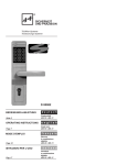
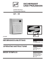
®
SICHERHEIT
UND PRÄZISION
Türöffner-Systeme
Türsteuerungs-Systeme
421 - 30
®
D 00073
BEDIENUNGS-ANLEITUNG
OPERATING INSTRUCTIONS
MODE D'EMPLOI
d e u t s c h
KompaktTürcodegerät 421 - 30
e n g l i s h
Compact
Door Coding Unit
421 - 30
f r a n ç a i s
Appareil compact
d'ouverture de porte
par code d'accès
421 - 30
®
d e u t s c h
Kompakt
Türcodegerät 421 - 30
e n g l i s h
Compact
Door Coding Unit
421 - 30
f r a n ç a i s
Appareil compact
d'ouverture de porte
par code d'acces
421 - 30
2
Inhalt
Seite
Das vollelektronische/mikroprozessorgesteuerte
Kompakt-Türcodegerät 421 - 30
Allgemeine Beschreibung
Die Türöffner
Externe Türöffner-Taster
Codeschalter
Einstellung der Türentriegelungszeit
Externe Störeinflüsse -ResetTechnische Daten
3
3
3
3
3
4
4
Elektroinstallation
4
Contents:
Page
The fully electronic microprocessor-controlled
compact door coding unit 421-30
General description
Door releases
External door release push-buttons
Code switch
Setting the door unlocking period
External noise influences - reset
Technical specifications
Electrical wiring
5
5
5
5
5
6
6
6
Sommaire :
Centrale compacte à clavier intégré, avec électronique
et microprocesseur
Description générale
Gâche
Bouton-poussoir
Commutateurs de codage
Réglage du temps de déverrouillage
Influences perturbatrices externes - Reset
Caractéristiques techniques
Installation électrique
Page
7
7
7
7
7
8
8
8
d e u t s c h
Kompakt
Türcodegerät
421 - 30
Allgemeine Beschreibung
Türöffner mit Ruhestromfunktion
Das vollelektronische / mikroprozessorgesteuerte KompaktTürcodegerät 421-30 in Ein-Kanal-Ausführung bietet die
Anschlußmöglichkeit für eine Tür ( einen Elektro-Türöffner).
Diese Türcodeanlage arbeitet mit einem Zahlencode, der es
nur berechtigten Personen ermöglicht, einzelne Räume zu
begehen. Dieser Zahlencode kann jederzeit problemlos geändert und somit den jeweiligen Anforderungen angepaßt
werden. Das Kompakt-Türcodegerät 421-30 beinhaltet in
einem stabilen Metallgehäuse eine Frontplatten-Codetastatur,
Codeschalter, Auswerteelektronik und Netzteil. Die Codeschalter sind hinter der mit einem Zylinderschloß gesicherten Gerätetür angeordnet und nur mit einem Schlüssel
zugänglich. Das Türcodegerät wird im Handbereich der Tür
neben der Türzarge montiert und an das Netz angeschlossen. Der passende Elektro-Türöffner wird als Gegenstück
zum Türschloß in den Türrahmen eingebaut. Die Leitungsverbindung vom Türcode-Gerät zum Türöffner erfolgt mit
geschirmter Installationsleitung.
Der Ruhestrom-Türöffner z.B. 3405 ist ohne Spannung
entriegelt. Bei Stromausfall ist die Tür für jeglichen Zutritt
frei.
Funktion
Die über das Tastenfeld eingegebenen Codeziffern werden
in elekrische Signale umgesetzt und an das Steuergerät
weitergegeben. Hier werden sie mit den einprogrammierten
Daten verglichen. Ist die Zugangsberechtigung erkannt, schaltet das Türöffnerrelais für eine im Steuergerät voreingestellte
Zeit (Türentriegelungszeit), die Tür frei.
Türbeschläge
Außen Ziehknopf, innen Türdrücker (Wechselgarnitur),
Schloß mit Wechsel. Durch vorgenannten Türbeschlag kann
die Rauminnenseite jederzeit über den Türdrücker verlassen
werden.
Die Türöffner
Die mit der Türcodeanlage einzusetzenden Türöffner sind
die Modelle 1405/1705 bzw. 1405 RR/1705 RR (Arbeitsstromfunktion) und 3405/3705 bzw. 3405 RR/3705 RR
(Ruhestromfunktion).
Es wird grundsätzlich empfohlen, Türöffner mit Rückmeldekontakten ( Bestellzusatz "RR") zu verwenden.
Türöffner mit Arbeitsstromfunktion
Der Arbeitsstrom-Türöffner z.B. 1405 ist mit Spannung entriegelt. Bei Stromausfall bleibt die Verschlußsicherheit der
Tür gewährleistet.
Türöffner mit Rückmeldekontakten Bestellzusatz "RR"
Automatisches Rücksetzen des Türöffnerrelais bei aufgemachter Tür. Somit ist die anschließend zugemachte Tür
sofort wieder verriegelt.
Technische Daten:
1405/1405 RR Nennspannung 12 V(Spannungstoleranz 11 - 13 V-)
Stromaufnahme 200 mA, 100% ED
1705/1705 RR Nennspannung 12 V(Spannungstoleranz 11 - 13 V-)
Stromaufnahme 230 mA, 100% ED
3405/3405 RR Nennspannung 12 V(Spannungstoleranz 11 - 13 V-)
Stromaufnahme 200 mA, 100% ED
3705/3705 RR Nennspannung 12 V(Spannungstoleranz 11 - 13 V-)
Stromaufnahme 230 mA, 100% ED
Externe Türöffnertaster
Mittels bauseitiger bzw. externer Türöffnertaster kann die
Tür in gewohnter Weise von Innenräumen geöffnet werden.
Der Türöffner wird dann über die voreingestellte
Türentriegelungszeit (Funktionsdrehschalter Türentriegelungszeit) entriegelt.
Codeschalter
An den auf der Anschlußplatine befindlichen Codeschalter
läßt sich leicht die gewünschte 4-stellige Codezahl einstellen.
Einstellung der Türentriegelungszeit
"Drehschalter Türentriegelungszeit" Auf der Türcodeanlage befindet sich ein Drehschalter, der zur Einstellung der
Türentriegelungszeit dient. Diese Einstellung bestimmt die
Zeit, in der die Tür geöffnet werden kann, nachdem die
richtige Codezahl eingegeben wurde. Der Einstellbereich
ist von 1 - 30 Sekunden wählbar.
Raster 1 Teilstrich = 2 Sek. Türentriegelungszeit (max. 30
Sek. einstellbar)
Bei Verwendung von Türöffnern mit Rückmeldekontakten
"RR" (siehe Anschlußschaltbild), wird die Türentriegelungszeit beim Öffnen der Tür zurückgestellt. Somit ist
die anschließend zugemachte Tür sofort wieder verriegelt.
3
d e u t s c h
Kompakt
Türcodegerät
421 - 30
Externe Störeinflüsse - Reset Trotz interner Schutzmaßnahmen können außergewöhnlich starke Störfelder eine Störung der mikroprozessorgesteuerten Türcodeanlage herbeiführen. Störeinflüsse
können verhindert werden, wenn bei der Installation folgende Punkte beachtet werden:
- Gerät nicht in unmittelbarer Nähe von induktiven
Verbrauchern montieren.
- Separate Leitung für Netzspannungsversorgung
verlegen (evtl. Netzfilter).
- Induktive Verbraucher entstören (Varistor,
RC-Glied)
Nach Störungsbeseitigung ist die Neuinbetriebnahme
(Reset) der Türcodeanlage erforderlich. Hierzu müssen die
Reset-Stifte, die sich auf der Hauptplatine befinden, kurzzeitig überbrückt werden.
Technische Daten:
Anschlußspannung
220 V WS +10%/-10%
Nennfrequenz
50 - 60 Hz
Leistungsaufnahme Leerlauf
6,5 VA
Leistungsaufnahme Vollast
9,5 VA
Betriebsnennspannung
12 Vmax. Belastbarkeit
0,25 A
Relaiskontakt Schaltleistung
120 VA max.
Schaltspannung max.
24 V
Schaltstrom max.
1A
Freigabezeit
1 - 30 sek.
Betriebstemperatur
00 C bis 400 C
Feuchteklasse nach DIN 40 040 F
Schutzart nach DIN 40 050
IP 30
Gehäuse:
Alu-Druckguß, pulverbeschichtet
Farbton grauweiß
RAL 9002
Abmessungen (B x H x T)
120 x 145 x 57 mm
®
Elektro-Installation
7
421 - 30
–
8
9
4 5 6
1 2 3
+ 0 –
2-adrig abgeschirmt
(4-adrig abgeschirmt nur bei Türöffner RR)
2-adrig abgeschirmt
~
Elektro-Türöffner
Türöffner-Taster
3
220 V / 50 - 60 Hz
NYM 3 x 1,5 mm2
4
e n g l i s h
Compact Door
Coding Unit
421 - 30
General description
Door release in nonenergized mode:
The fully electronic-/microprocessor-controlled compact
door coding unit 421-30 in the single channel version
provides facilities for the connection of one door (one
electric door release). This door coding unit functions with
a numeric code which enables only authorized personnel
to gain access to individual rooms. This numeric code
is amendable at any time without any problem and is thus
adaptable to the respective requirements.
Residing in a robust metal enclosure the compact door
coding unit 421-30 comprises a front panel coding keypad,
code switch, evaluation electronics and power unit. The
code switches are arranged behind the equipment door
which is secured by means of a cylinder lock and which is
accessible only by means of a key. The door coding unit is
usually mounted within hand reach of the door beside the
door frame and is connected to the mains. The appropriate
electric door release is fitted into the door frame in the form
of a counterpart to the door lock. The lead connection
between the door coding unit and the door release is
effected using screened wiring.
The nonenergized mode door release, e.g. 3405, is
unlocked when not under voltage. In the event of a power
failure the door provides free access.
Function
The code numbers entered via the keypad are converted
into electrical signals and passed on to the control device.
There they are compared with the programmed data. If
access entitlement is identified the door release relay will
switch to release for a time period (door unlocking period)
that has been preset in the control device.
Door hardware:
Outside pull knob, inside door handle (interchangeable set),
lock with change-over. The room interior can be left at any
time using the door handle due to the afore mentioned door
hardware.
Door release with check-back
contacts, ordering suffix "RR"
position indicator
Automatic resetting of the door release relay when the door
is opened. Thus the subsequently closed door is
immediately relocked.
Technical specifications
1405/1405 RR voltage rating 12 V (voltage tolerance
11 - 13 V) power consumption
200 mA, continuous duty
1705/1705 RR voltage rating 12 V (voltage tolerance
11 - 13 V) power consumption
230 mA, continuous duty
3405/3405 RR voltage rating 12 V (voltage tolerance
11 - 13 V) power consumption
200 mA, continuous duty
3705/3705 RR voltage rating 12 V (voltage tolerance
11 - 13 V) power consumption
230 mA, continuous duty
External door release push-buttons
The door can be opened in the usual way from internal
rooms by means of door release push-buttons provided
on site or externally. The door release is then unlocked via
the preset door unlocking period (rotary function switch for
door unlocking period).
Code switch
The desired 4-digit code number is easily settable via the
code switch on the connection board.
Door releases
Setting of the door unlocking period
The door releases to be utilized together with the door
coding system are the models 1405/1705 or 1405 RR/1705
RR (energized mode) and 3405/3705 or 3405 RR/3705 RR
(nonenergized mode). It is recommended fundamentally to
use only electric strikes with integrated monitoring contact.
Door release in energized mode
The energized mode door release, e.g. 1405, is unlocked
when under voltage. In the event of a power failure the
locking security of the door is guaranteed.
"Rotary function switch for door unlocking period". A rotary
switch is located on the connection board of the door coding
system, the purpose of which is the setting of the door
unlocking period. This setting determines the time period
during which the door can be opened after the correct code
number has been entered. The setting range is selectable
between 1 - 30 seconds.
Graduation 1 increment = 2 secs. door unlocking period
(settable to 30 secs. max.)
If door releases with check-back position indicator contacts
"RR" are being used (see connection circuit diagram), the
door unlocking period is reset upon the door being opened.
5
e n g l i s h
Compact Door
Coding Unit
421 - 30
External noise influences - reset
Technical specifications:
Connected voltage
Despite internal proofing measures exceptionally strong
noise fields can bring about a malfunction of the
microprocessor-controlled door coding system.
Noise influences can be prevented if the following points
are heeded during installation:
- Do not mount the unit in the immediate vicinity
of inductive power consumers.
- Lay a separate line for mains voltage supply
(possibly using a mains filter)
- Suppress any inductive power consumers
(varistors, RC-sections)
After elimination of the noise, resetting of the door coding
system is necessary. For this purpose the reset pins, which
are located on the main board, have to be bypassed briefly.
220 V AC
+ 10 % / - 10 %
50 - 60 Hz
6.5 VA max.
9.5 VA max.
12 V
0.25 A max.
Frequency
Power consumption idling
Power consumption full load
Rated operating voltage
Load capacity
Relay contact
Max. switching power
120 VA
Max. switching voltage
24 V
Max. switching current
1A
Release period
1-30 secs.
Operating temperature
0 °C to 40 °C
Moisture class as
per DIN 40 040
F
Degree of protection as per DIN 40 050
IP 30
Enclosure:
aluminium die-casting,
powder-coated Colour grey white
RAL 9002
Dimensions (w x h x d)
120 x 145 x 57 mm
Electrical Wiring
7
421 - 30
–
8
9
4 5 6
1 2 3
+ 0 –
(screened 4-conductor
only for door releases with „RR“)
screened 2-conductor
~
electric door release
door release push-button
3
220 V / 50 - 60 Hz
2
NYM 3 x 1,5 mm
6
f r a n ç a i s
Centrale compacte
à clavier intégré
421 - 30
Déscription générale
La centrale compacte à clavier intégré 421-30 est
commandée par un microprocesseur, qui lui permet de
gérer l‘accès d‘une porte. Le système est basé sur un code
numérique qui autorise l‘ouverture de la porte à la personne
connaissant le code programmé. Une manipulation des
plus simples permet de modifier le code en fonction des
besoins. Le boîtier métallique robuste comprend le clavier
à touches numériques, les commutateur de codage, le
système électronique d‘exploitation et le bloc d‘alimentation.
Les commutateurs de codage sont logés derrière le couvercle
du boîtier, fermé à clé. La centrale compacte à clavier
intégré est à poser à proximité immédiate de la porte dont
elle libère l‘accès. La gâche électrique adéquate est installée
dans le chambranle. Un câble avec écran assure la liaison
électrique entre la centrale et la gâche.
Fonctionnement
Les chiffres tapés sur le clavier sont convertis en signaux
électriques et transmis au système de commande qui les
compare aux chiffres programmés. Si le code est identifié,
l‘accès est autorisé et le relais de la gâche se libère pendant
une durée enregistrée au préalable dans la centrale de
commande (temps de déverrouillage de la porte).
Garniture de porte:
Poignée à l‘extérieur et pommeau à l‘intérieur (garniture
interchangeable), serrure avec cliquet de déblocage. Tant
que le cliquet est en position passive, il est possible de
quitter la pièce à tout moment en poussant sur le pommeau
de la porte.
Gâche avec contact de fond de pêne, suffixe de
référence: "RR"
A l‘ouverture de la porte, le relais de gâche repositionne
automatiquement de sorte que la porte refermée est
immédiatement verrouillée en se refermant.
Caractéristiques techniques:
1405/1405 RR Tension nominale 12 V (tension admise: de 11 V à 13 V)
Consommation de courant: 200 mA
Gâche sous tension permanente
1705/1705 RR Tension nominal 12 V (tension admise: de 11 V à 13 V)
Consommation de courant: 230 mA
Gâche sous tension permanente
3405/3405 RR Tension nominal 12 V (tension admise: de 11 V à 13 V)
Consommation de courant: 200 mA
3705/3705 RR Tension nominal 12 V (tension admise: de 11 V à 13 V)
Consommation de courant: 230 mA
Bouton-poussoir
Un bouton-poussoir permet d‘ouvrir normalement la porte
de l‘intérieur. La durée de libération de la gâche est alors
fonction du temps de déverrouillage programmé (bouton de
réglage du temps de déverrouillage).
Gâche
Commutateur de codage
La centrale compacte 421-30 implique l‘utilisation d‘une
gâche parmi les modèles suivants: 1405/1705 et 1405 RR/
1705 RR (courant de travail) ou bien 3405/3705 et 3405 RR/
3705 RR (courant de repos). On recommande en principe
l‘emploi de gâches avec contact de fond de pêne (suffixe de
référence: "RR").
Les commutateurs de codage situés sur la platine de
raccordement permettent de programmer facilement le
code à 4 chiffres.
Gâche fonctionnant en courant de travail
La gâche fonctionnant en courant de travail, par ex. 1405,
est déverrouillée sous tension, le verrouillage restant ainsi
garanti en cas de rupture de courant.
Gâche fonctionnant en courant de repos
La gâche fonctiomant en courant de repos, par ex. 3405, est
déverrouillée en l‘absence de courant, ce qui signifie qu‘en
cas de rupture de l‘alimentation électrique, la porte est
libérée et peut être franchie à tout moment.
Réglage du temps de verrouillage
La centrale porte un bouton de réglage du temps de
déverrouillage de la porte. C‘est le temps pendant lequel la
porte est libérée. Il peut être réglé entre 2 et 30 secondes.
1 trait de la graduation = 2 secondes.
Dans le cas d‘une gâche "RR" à contact de fond de pêne
(voir schéma électrique), celle-ci est libérée jusqu‘à ce
qu‘on ouvre la porte et se retrouve verrouillée dès que la
porte se referme, même si la durée programmée n‘est pas
encore écoulée totalement.
7
f r a n ç a i s
Centrale compacte
à clavier intégré
421 - 30
Influences perturbatrices externes - Reset
En dépit des mesures de protection internes, des champs
parasitaires importants peuvent intervenir et dérégler le
système de codage. Un certain nombre de précautions à
prendre à l‘installation peuvent mettre la centrale à l‘abri de
telles perturbations:
– Ne pas installer la centrale à proximité d‘appareils
à induction
– Utiliser un câble d‘alimentation secteur
séparé (éventuellement, récourir à un filtre
secteur)
– Antiparasiter les récepteurs inductifs (varistor,
circuit RC).
Lorsqu‘il y a eu un dérangement, il est nécessaire de
réinitialiser le système de codage en faisant un Reset. A
cette fin, shunter un bref instant les broches Reset de
remise à zero qui se trouvent sur la platine principale.
®®Caractéristiques techniques
Tension de raccordement
Fréquence nominale
Consommation en veille
Consommation en pleine charge
Tension nominal de fonctionnement
Consommation max.
Spécification du Contact relais:
Pouvoir de coupure en puissance
Pouvoir de coupure en tension
Pouvoir de coupure en courant
Temps de réaction du relais de gâche
Température de fonctionnement
Classe de protection selon DIN 40 040
Classe de protection selon DIN 40 050
Boîtier:
fonte d‘aluminium fritté
Couleur: blanc gris
Dimensions (L x H x P)
220 V +- 10 %
50/60 Hz
6,5 VA
9,5 VA
12 V CC
0,25 A
max. 120 W
max. 24 V
max. 1 A
1 à 30 secondes
0°C à 40°C
F
IP 30
RAL 9002
120 x 45 x 57 mm
®
Installation électrique
7
421 - 30
–
8
9
4 5 6
1 2 3
+ 0 –
Câble avec écran
(4 fils seulement avec les gâches „RR„)
Câble avec écran à 2 fils
~
Gâche électrique
Bouton-poussoir
3
220 V / 50 - 60 Hz
2
VGN 3 x 1,5 mm
8
Grundplatine
Drehschalter
Türentriegelungszeit
Einstellbereich
1 - 30 sec.
Codeschalter
Reset
1
1
Ausgangsspannung
12 V –
max. Belastbarkeit
0,25 A
1
Si 1
0,5 AT
Schaltspannung
max. 24 V AC
Schaltstrom
max. 1 A
Schiebeschalter
Test der Tastenfunktionsfähigkeit
1
12 V –
Türöffner
Relais
TÖ
Trafo
220 V AC
L
N
TÜ
Tast.
1
2
3
4
5
7
6
L
grün
gelb
grau
rot
blau
Zentrale Erdanschlußklemme im
Gehäuse
Kabelschirme
auflegen
N
PE
Türöffner-Taster
extern
Auf richtige Polarität
achten !
Arbeitsstrom-Türöffner 1405/ 1405 RR
12 V –
1
2
Türöffner
Relais
3
4
TÖ
5
6
TÜ
7
Automatische Rückstellung:
Anschluß bewirkt das automatische Rücksetzen des
Türöffnerrelais bei geöffneter Tür, so daß die anschließend geschlossene Tür sofort wieder gewsperrt ist.
Türöffner mit Rückmeldung Modell ...RR erforderlich.
grün
gelb
grau
rot
blau
Bei Verzicht auf automatische Rückstellung Anschluß
TÜ nicht belegen, Türöffner verriegelt dann nach Ablauf
der Türfreigabezeit.
Auf richtige Polarität
achten !
Ruhestrom-Türöffner 3405/ 3406 RR
Tastaturplatine
Schiebeschalter
Dauerentriegelung
9
Main board
Turn switch time
of unlocking
setting range
1 - 30 sec.
Code switch
Reset
1
1
Output voltage
12 V –
max. currentcarrying capacity
0,25 A
1
Si 1
0,5 AT
turn-on voltage
max. 24 V AC
switching current
max. 1 A
Sliding switch
test of the key’s
operatability
1
12 V –
Door opener’s
TÖ
relay
Transformer
220 V AC
L
N
TÜ
Connector
1
2
3
4
5
6
7
Earth terminal
in the housing
green
yellow
grey
red
blue
shielding
L
N
PE
External
push button
Pay attention to the
correct polarity !
Normally closed latches mod. 1405/ 1405 RR
5
6
TÜ
7
yellow
4
green
3
grey
2
blue
1
Door opener’s
TÖ
relay
red
12 V –
Automatic readjusting:
Due to this connection the relay of the door opener is
readjusted if the door is open.
The closed door will immediatly be closed agian.
Door openers with monitor contacts are necessary.
If you do not want an automatic readjusting, do not
overlay the connection TÜ. The door is locked when the
enable time of the door is gone off.
Pay attention to the
correct polarity !
Normally open latches mod. 3405/ 3406 RR
Keypad board
Sliding switch
permanent unlocking
10
Platine de base
Temporisation de
décondamnation
1 à 30 sec.
Composition du code
Reset
1
1
Tension de sortie
12 V –
intensité max. admissible de courant
0,25 A
1
Si 1
0,5 AT
Tension de coupure
max. 24 V AC
courant de
commutation
max. 1 A
Interrupteur à
coulisse
test de la capabilité
de fonctionner des
touches
1
12 V –
1
relais de
gâche électr.
2
3
4
5
TÖ
TÜ
6
7
Transformateur
fiche de
connexion
220 V AC
L
N
vert
jaune
gris
rouge
bleu
Bornier de mise
à la terre
L
N
PE
Bouton
poussoir externe
Attention à la
polarité !
Gâches électriques travaillant par établissement en
courant continu mod. 1405/ 1405 RR
12 V –
1
2
Relais de
gâche électr.
3
4
5
TÖ
6
TÜ
7
Rappel automatique
du relais lors de la ouverture de la porte qui sera immédiatement condamnée.
I est nécessaire d’utiliser des gâches à 2 microcontacts ert
de se brancher sur TÜ.
vert
jaune
gris
rouge
bleu
Porte recondamnée à la fermeture selon la temporisation.
Ne pas se brancher sur TÜ.
Attention à la
polarité !
Gâches électriques travaillant par coupure
(courant positif) mod. 3405/ 3406 RR
Platine de clavier
Interrupteur à coulisse
décondamnation indéterminée
11
®
Das Unternehmen
The company
L´entreprise effeff
effeff - ein starkes und
technologie-orientiertes Unternehmen hat ein unverwechselbares, in über 50jähriger Firmengeschichte
gewachsenes Profil. Das
Unternehmen, das heute
über 700 Mitarbeiter beschäftigt, gilt in seinen Märkten als ein Haus, das Konzeptionen prägt und Richtungen weist. Strenge Orientierung an Zukunfts-Technologien und die konsequente Realisierung technologischer Spitzenlösungen haben effeff zu seiner
qualifizierten Marktposition
geführt.
effeff - a dynamic, technologically oriented enterprise
whose unmistakable profile
is the culmination of over 50
years of successful company history. Today employing
a staff of over 700, the company enjoys a reputation in
the markets it serves for progressive technological development and trailblazing
concepts. It is dedication to
the technologies of the future and a consistent record
in realizing outstanding solutions which have placed
effeff in its qualified market
position.
Une entreprise à très fort
développement technologique qui bénéficie d´une expérience de plus de 50 ans,
ce qui lui assure une réputation imcomparable.
Plus de 700 ouvriers et
cadres s´emploient à faire la
réputation de la marque et à
respecter les orientations,
garanties de leur réussite
dans le domaine de la technologie de pointe et d´avenir.
Konsequente SystemTechnik
Die komplette Lösung aus
einer Hand ist klare effeffLinie. effeff entwickelt und
produziert nahezu alle Komponenten im eigenen Hause. So entstehen integrierte
und technologisch im Detail
aufeinander abgestimmte
Lösungen. effeff-Systeme
sind richtungsweisende
Komplett-Lösungen: die Anlagen sind aus einem Guß.
effeff ist heute der führende
deutsche Hersteller, ein professioneller, engagierter
und anwendungs-orientierter Partner.
Consistent
and systematic
engineering
effeff follows a consistent
policy of offering complete
solution packages. Practically all used components
are developed and produced
under the company´s own
roof, thus offering custumers
integrated system solutions
coordinated down to the last
detail. effeff systems lead
the market with complete,
open-ended solutions from
a single competent source.
Today, effeff is the leading
producer of electromechanical and electronical security; a committed and professional partner oriented towards practical application.
Not only in Germany, but
also in Europe!
®
©'94 PRINZ/PARTNER D 723 79 Hechingen – Printed in Germany –
SICHERHEIT
UND PRÄZISION
Efficacité
des systèmes effeff
La devise de effeff est de
viser une fabrication totalement intégrée pour assurer une évolution constante
et une parfaite fiabilité entre
les produits dans leur moindre détail technologique.
effeff a l´avantage d´offrir
des systèmes et des ensembles complets. effeff se
trouve à ce jour le leader des
fabricants allemands dans
son orientation et sa particularité professionnelle.
effeff – in mehr als 60
Ländern der Erde
ein Markenzeichen für
Sicherheit und Präzision.
effeff – Fritz Fuss GmbH & Co.
Elektrotechnische Fabrik
Postfach 490
D 72425 Albstadt
Telefon 074 31 . 123 - 0
Telefax 074 31 . 123 240 oder 123 303
Telex 763 731 ffus d