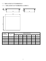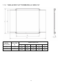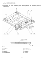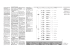
1
Modules for electronic weighing
Module für die elektronische Wägung
Module pour pesage électronique
Moduli per pesatura elettronica
ELECTRONIC PLATFORMS
ELEKTRONISCHE PLATTFORMEN SERIE
PLATE-FORME ELECTRONIQUE SERIE
PIATTAFORME ELETTRONICHE SERIE
"FL" / “FLP”
Installation and operating manual
Installations- und Betriebshandbuch
Instruction d’installation et d’utilisation
Istruzioni di installazione e d’uso
FL-FLP_13.02_EN_DE_FR_IT
LANGUAGES
SPRACHEN
LANGUES
LINGUE
ENGLISH ................................................................................................1
DEUTSCH .............................................................................................15
FRANÇAIS ............................................................................................29
ITALIANO .............................................................................................43
ENGLISH
INDEX
IMPORTANT WARNINGS ..................................................................................................................... 2
1.INTRODUCTION................................................................................................................................. 3
1.1. TECHNICAL SPECIFICATIONS ............................................................................................. 3
1.2. TABLE OF THE PLATFORM .................................................................................................. 4
1.2.1.
1.2.2.
TABLE OF FL SERIES PLATFORM .............................................................................................................4
TABLE OF FLP SERIES PLATFORM ..........................................................................................................5
2.INSTALLATION OF THE PLATFORMS ON THE FLOOR ................................................................. 6
2.1. UNPACKING THE PRODUCT ................................................................................................ 6
2.2. INSTALLATION E CONNECTION........................................................................................... 6
2.2.1.
2.2.2.
INSTALLATION AND CONNECTION FL SERIES .......................................................................................6
INSTALLATION AND CONNECTION FLP SERIES .....................................................................................8
3.INSTALLING THE CSP COLUMN.................................................................................................... 10
4.MAINTENANCE AND REPAIRS ...................................................................................................... 11
4.1. TO OBTAIN THE BEST PERFORMANCE ............................................................................ 11
4.2. BREAKDOWNS AND OVERLOADS ..................................................................................... 11
5.TRANSPORTATION OF THE PLATFORM ...................................................................................... 11
6.INSTRUCTIONS FOR EQUALIZING THE FL PLATFORMS ........................................................... 12
7.PLATFORM SHIELDED CABLE AND CONNECTOR ..................................................................... 13
WARRANTY ........................................................................................................................................ 14
AUTHORIZED SERVICE CENTER STAMP ........................................................................................ 14
1
IMPORTANT WARNINGS
Make sure the following conditions are met:
- Flat, level, stable support surface isolated from vibrations, dust, and corrosive vapours.
- Moderate temperature and humidity (15-30°C and 40-70%). No large air draughts.
- Main power supply restricted to within + 10% ÷ - 15% of the rated voltage.
- Adjust the feet of the platform until the air bubble level is centred
-Temperature and humidity moderated (do not expose to direct light of the sun, or near a source
of heat )
- floor hardness of at least 100 kg/cm2
Make sure that the platform is level by adjusting the feet and checking the level (see instructions in
section Errore. L'origine riferimento non è stata trovata.).
Do not weld, perforate or modify the structure without consulting the reseller. If it is damaged or
tampered with the warranty conditions will be annulled.
If the place of use is a humid or wet environment, the installation must be carried out in such a way so
that water stagnation and/or scraps under the structure are avoided.
The platform must be connected to a weigh indicator using the fitted cable, following the indicator’s
instructions.
Do not step, crush or expose to sunlight the connecting screen cable.
YOU NEED TO GROUND the metallic structure of the platform, especially if you need to weigh
materials that, while handled, can cause electrical discharges (dust, plastic materials, etc.). If there
are any doubts, consult the reseller.
DO NOT INSTALL IN HAZARDOUS ENVIRONMENTS.
(unless specifically made for this use)
Do not use solvents when cleaning.
2
1. INTRODUCTION
All FL / FLP series weighing modules are built with high quality materials and are calibrated in such a
way which guarantees full reliability and weighing accuracy that will lasts in time. The measuring
elements are 4 load cells, produced in conformance to the OIML R60 standards.
The FL / FLP platforms have equalised load cells, connected to each other through a junction box IP67
fitted with a 4-pole shielded cable 3 meters long used for the connection to the weight indicator.
Every FL / FLP weighing module is built and engineered to guarantee a uniform detection of the load
on the load cell weighing modules, even in adverse environment conditions.
The FL / FLP electronic platforms are built in such a way so that they can be used in various industrial
applications (simple weighing, batching, belt weighing, etc.). With a weight capacity ranging from 600
kg to 3.000 kg, they also permits a wide range of applications (see paragraph 1.2).
The platforms are built to perform efficiently in any type of environment. They are protected from a
STATIC overload of over 200% of the nominal platform capacity.
1.1. TECHNICAL SPECIFICATIONS
Structure
Load cells
Max power supply tension tolerated
Nominal output (nickel-plated steel cell)
Combined error
Compensated Temperature Range
Operating Temperature Range
Cell Resistance
Input
Output
Mod. FL: Monobloc with
oven-fire painted steel tubulars.
Fixed sheet steel load surface.
Mod. FLP: Chequered steel structure and load
surface, oven-fire painted, RAL 5007 blue.
SHEAR BEAM
Max 15 VDC
2 or 3 mV/V +/- 0,25% (depending on the model)
< 0,03 % FSO
-10°C / +40°c
-18°C / +65°C
350 Ohm
350 Ohm
3
1.2. TABLE OF THE PLATFORM
1.2.1. TABLE OF FL SERIES PLATFORM
DIMENSIONS mm
PLATFORM
MODE
MAX LOAD
kg
A
B
FLA
600 / 1500
1000
FLB
600 / 1500
FLD
D
E
F
1000
C
(min-max)
100 – 120
900
900
60
1250
1250
100 – 120
1150
1150
60
1500 / 3000
1250
1500
100 – 120
1150
1400
60
FLE
1500 / 3000
1500
1500
100 – 120
1400
1400
60
FLM
600 / 1500
1000
1250
100 – 120
900
1150
60
4
1.2.2. TABLE OF FLP SERIES PLATFORM
DIMENSIONS mm
PLATFORM
MODEL
MAX LOAD
kg
A
B
C
D
E
FLPA
3000
1950
1000
1425
1250
52
FLPB
3000
2200
1250
1675
1500
52
5
2. INSTALLATION OF THE PLATFORMS ON THE FLOOR
NOTE: The weighing module must be connected to its appropriate weight indicator with the cable
coming from the junction box.
The indicator, connected to the platforms, can not be calibrated if not powered.
It is the customer’s responsibility to prepare and calibrate the indicator.
For any further detail, refer to the technical manual, supplied with the indicator.
2.1. UNPACKING THE PRODUCT
a) Unpack the product.
b) Check if any damage was caused by the transportation and make sure that there are:
1 Platform, 4 springs, 4 feet, 1 connection cable, 2 eyebolts and 1 installation manual.
2.2. INSTALLATION E CONNECTION
2.2.1. INSTALLATION AND CONNECTION FL SERIES
MAKE SURE TO FOLLOW THE WARNINGS ON PAGE 2.
Refer to drawing 1 of the next page.
Follow this procedure when positioning the platform:
a) Unscrew completely and remove the two screw cap (Fig. 2) and screw the two eyebolts. Lift the
side of the platform and screw completely the feet (2) on the cells (3). NEVER UNLOOSE THE
BOLTS (4).
b) Level the platform by screwing the screw under the cap (Fig. 2) until the bubble (5) is in the centre
of the level. The stability of the platform is very important.
All the corners MUST REST IN A UNIFORM WAY. Carefully check that all feet fully rest on the
ground and that the platform, loaded on the corner, is not unstable (if a corner is not resting on the
ground its relative foot is easier to turn).
Furthermore, in order to maintain the platform performance, the feet must be adjusted in order that
the height (C) of the platform corresponds to that shown in the table in page 4.
c) The calibration should be done 15 minutes after the indicator has been turned on.
d) Calibrate the indicator following the instructions on its technical manual.
e) Check the corners (see paragraph 6) of the platform by positioning on these (one at a time) a
weight equal to 1/3 of the indicator’s maximum capacity. Check that the error is not greater than + /
- 2 divisions and If this is not the case, contact the RESELLER.
f) Using a reference weight, check the zero and the full-scale capacity.
6
Fig. 1
1)
2)
3)
4)
Loading top
Foot
Load cell
Bolts
5)
6)
7)
8)
7
Level bubble
Junction box
Screw
Cage
Fig. 2
2.2.2. INSTALLATION AND CONNECTION FLP SERIES
MAKE SURE TO FOLLOW THE WARNINGS ON PAGE 2.
Refer to drawing 3 of the next page.
Follow this procedure when positioning the platform:
a) Unscrew completely and remove the two screw cap (8) and screw the two eyebolts. Lift the side of
the platform and mount the feet (2) on the cells (3). NEVER UNLOOSE THE BOLTS (4). Attach
side bars (7) and mount the ramps (9).
b) Level the platform by inserting shims under the feet until the bubble (5) is in the centre of the level.
The stability of the platform is very important.
All the corners MUST REST IN A UNIFORM WAY. Carefully check that all feet fully rest on the
ground and that the platform, loaded on the corner, is not unstable (if a corner is not resting on the
ground its relative foot is easier to turn).
Furthermore, in order to maintain the platform performance, the feet must be adjusted in order that
the height (E) of the platform corresponds to that shown in the table in page 5.
c) The calibration should be done 15 minutes after the indicator has been turned on.
d) Calibrate the indicator following the instructions on its technical manual.
e) Check the corners (see paragraph 6) of the platform by positioning on these (one at a time) a
weight equal to 1/3 of the indicator’s maximum capacity. Check that the error is not greater than + /
- 2 divisions and If this is not the case, contact the RESELLER.
8
f) Using a reference weight, check the zero and the full-scale capacity.
Fig. 3
1)
2)
3)
4)
5)
6)
Loading top
Foot
Load cell
Bolts
Junction box
Screw
7) Side Bar
8) Screw cap
9) Loading ramp
10) Screened cable to the indicator
11) Level bubble
12) Bolts (Loading ramp)
9
3. INSTALLING THE CSP COLUMN
Refer to drawing 4 of the next page.
1. Lock column (2) to base (7) with the two fitted screws (10 and 3).
2. Screw nut on feet (8).
3. Screw the four feet (8) to the base (7).
4. Make the connecting cable, coming from the scale, run inside column (2) until you get it out from
hole.
5. Connect the cable to the terminal board referring to the indicator technical-user manual.
6. Lock column (2) to the support for the indicator (9 and 5) with the two fitted screws (11 and 5).
7. Set the weigh indicator (6) to the support (9) with screws (4). Make sure the cable, connecting the
scale, is stretched.
8. Set the column CSP perpendicular to the floor, by adjusting feet (8).
9. Thigh nut on feet (8).
Fig. 4
10
4. MAINTENANCE AND REPAIRS
4.1. TO OBTAIN THE BEST PERFORMANCE
-
One should keep the platform clean. If dirt and dust accumulate on the platform one should clean it
with a damp cloth or with the common cleaning products (do not use SOLVENTS and ACIDS)
- Avoid platform collisions because this could cause serious damages.
4.2. BREAKDOWNS AND OVERLOADS
If you think the platform is broken or damaged disconnect it in a permanent way. Do this if the platform:
- appears to be damaged
- does not work
- has been loaded more than its tolerable limits (which could happen during the transportation or at
time of storage)
5. TRANSPORTATION OF THE PLATFORM
To pack the platform follow the procedure below:
a) turn off the indicator
b) disconnect the platform’s indicator
c) remove the feet
11
6. INSTRUCTIONS FOR EQUALIZING THE PLATFORMS
1) Make 20 turns (clockwise) of the screws of all the trimmers in order to have the maximum signal on
all the cells. (On board there are 4 trimmers, one for each load cell)
EQUALIZATION BOARD
FLX
FLPX
2) Carry out the calibration with mass in the central point (i.e.: scale’s full scale capacity).
3) Place the sample weight (about 1/3 of the capacity) alternatively on each of the four angles of the
platform “1, 2, 3, 4” and identify the cell which shows the lowest weight.
PLATFORM CELL LAY-OUT
FLX
FLPX
LEVEL BUBBLE
12
4) Adjust the trimmers of the remaining 3 cells so that all three display the same weight as the cell with
the lowest weight; do as follows:
5) Position the sample weight on the angle corresponding to the cell with the greatest signal.
6) Turn (counter-clockwise) the screw of the trimmer of the corresponding cell until the weight equal to
that of the cell with the lowest signal is displayed.
7) Repeat steps “a” and “b” for the remaining two angles.
8) Check again making sure that on all four angles the same weight is displayed, otherwise adjust the
trimmers of the single cells as described in points 4 and 5.
9) Once again calibrate the scale.
Notes:
- So that the equalization is carried out well, it is advisable to use a small-sized sample weight having a
value which is about 1/3 of the capacity in order to concentrate the load on each single cell; the
equalization can be considered satisfactory if the weights displayed differ of about 1 division.
7. PLATFORM SHIELDED CABLE AND CONNECTOR
CABLE
Red
Black
Green
White
Shield
CONNECTOR 5-PIN
(SCALEHOUSE INDICATOR)
5
4
1
2
CONNECTOR 7-PIN
(DINI ARGEO INDICATOR)
1, 4
2, 3
6
5
13
MEANING
EXCITATION +
EXCITATION SIGNAL +
SIGNAL EARTH BRAIDING
WARRANTY
Scale House products are guaranteed for a period of twelve months
from delivery, excluding the parts classified as expendable materials
such as mechanical printing heads, batteries, electric motors and
wheels. The warranty for these expendable materials is three months.
The warranty refers to breakdowns resulting from any construction
defect or material defect of the product supplied and covers the cost
of labor and spare parts. The product must be returned to the Seller
address in its original packaging with shipping paid by the sender.
The warranty does not apply to breakdowns due to improper use or
non-observance of the operating instructions, electrical phenomenon,
unauthorized repair attempt, connection to other equipment or
removal of any product identification elements (serial number, label,
etc.). This warranty does not provide for any compensation for
damages, direct or indirect, incurred by the user due to complete or
partial failure of instruments, even during the warranty period. The
warranty for the load cells excludes the damages caused by knocks
and overloads.
AUTHORIZED SERVICE CENTER STAMP
14
DEUTSCH
INHALT
WICHTIGE HINWEISE......................................................................................................................... 16
1.EINLEITUNG .................................................................................................................................... 17
1.1. TECHNISCHE DATEN .......................................................................................................... 17
1.1. TABELLE DER PLATTFORMMODELLE: SERIE .................................................................. 18
1.1.1.
1.1.2.
TABELLE DER PLATTFORMMODELLE: SERIE FL .................................................................................. 18
TABELLE DER PLATTFORMMODELLE: SERIE FLP................................................................................ 19
2.BODENEBENE INSTALLATION DER PLATTFORMEN.................................................................. 20
2.1. ÖFFNEN DER VERPACKUNG ............................................................................................ 20
2.2. INSTALLATION UND ANSCHLUSS ..................................................................................... 20
2.2.1.
2.2.2.
INSTALLATION UND ANSCHLUSS DER PLATTFORMEN SERIE FL ...................................................... 20
INSTALLATION UND ANSCHLUSS DER PLATTFORMEN SERIE FLP ................................................... 22
3.ANWEISUNGEN FÜR DIE STATIVMONTAGE CSP ........................................................................ 24
4.WARTUNG UND REPARATUR ....................................................................................................... 25
4.1. ZUR ERZIELUNG OPTIMALER LEISTUNGEN: ................................................................... 25
4.2. SCHÄDEN UND ÜBERLASTUNG ........................................................................................ 25
5.TRANSPORT DER PLATTFORM .................................................................................................... 25
6.ANWEISUNGEN FÜR DIE ENTZERRUNG DER PLATTFORM ....................................................... 26
7.ABGESCHIMTES WAAGENKABEL UND STECKER ..................................................................... 27
GARANTIE .......................................................................................................................................... 28
STEMPEL DER KUNDENDIENSTSTELLE ......................................................................................... 28
15
WICHTIGE HINWEISE
Stellen Sie die Plattform in einer Umgebung auf, wo die folgenden Bedingungen beachtet
werden:
- Gerade und ebene Aufstellfläche,
- Stabilität und keine Vibration,
- Staubfrei und ohne aggressive Dämpfe,
- Ohne Luftströmungen,
- Gemäßigte Temperatur und Feuchtigkeit (vor direkter Sonnenbestrahlung schützen und von
Wärmequellen fernhalten).
- Bodenhärte mindestens 100Kg/cm2
Sicherstellen, dass die Plattform unter Nutzung der höheneinstellbaren Füße und der Libelle eben
ausgerichtet ist (siehe Punkt 2.2).
Die Struktur nicht ohne Zustimmung des Konstrukteurs schweißen, durchbohren oder verändern.
Eventuelle Schäden oder unsachgemäßer Gebrauch löschen jeden Garantieanspruch.
Falls der Gebrauchsort feucht oder nass ist, muß bei der Installation darauf geachtet werden, dass
keine Wasseransammlungen oder –rückstaus und/oder Bohrklein unter der Struktur sind.
Die Plattform muss über das von der Wägezelle kommende Kabel an eine Gewichtsanzeige
angeschlossen werden. Befolgen Sie dafür bitte die Anweisungen für die Anzeige.
Das Verbindungs-Abschirmkabel nicht quetschen oder darauf treten oder Wärmequellen aussetzen.
ERDEN Sie die metallische Struktur der Plattform. Dies ist besonders wichtig, wenn Material gewogen
wird, das elektrostatische Entladungen bewirken kann (Staub, Materialien aus Plastik, etc.).
Fragen Sie im Zweifelsfall den Verkäufer.
NICHT IN BEREICHEN MIT EXPLOSIONSGEFAHR INSTALLIEREN.
(Es sei denn, sie ist extra dafür vorgesehen)
Keine Lösungsmittel für die Reinigung benutzen.
16
1. EINLEITUNG
Alle Wagenmodule der Serie FL / FLP sind aus qualitativ hochwertigen Materialien hergestellt so dass
eine langlebige Zuverlässigkeit und Wägegenauigkeit garantiert ist. Die Messelemente bestehen aus 4
Wägezellen hergestellt gemäß der OIML R60 Standards.
Die FL / FLP Plattformen haben abgeglichene Wägezellen, miteinander verbunden über einen
Kabelkasten ausgerüstet mit einem 4-poligen abgeschirmten Kabel mit 3 m Länge für den Anschluss
an das Gewichtsanzeigegerät.
Jedes FL / FLP Wagenmodul ist gebaut und ausgelgt um eine gleichmäßige Erfassung der auf den
Wägezellenmodulen aufliegenden Last auch unter widrigen Umständen zu garantieren.
Die elektronischen Plattformen FL / FLP sind für dem Einsatz der unterschiedlichsten industriellen
Anwendungen ausgelegt. (einfaches Wägen, Befüllung, Bandwägung, etc.). Mit Wägebereichen von
600 kg bis 3.000 kg erlauben sie eine große Bandbreite von Anwendungen (siehe Punkt 1.1).
Die Plattformen sind gebaut um effiziente Leistung in jedem Bereich zu bringen. Sie sind gegen
STATISCHE Überlast von über 200% des nominalen Plattform-Wägebereiches geschützt.
1.1. TECHNISCHE DATEN
Struktur
Mod. FL: Kompakte Form, einbrenn-lackiert,
verstellbare Lastfüsse, Libelle.
Verschweißte Stahllastplatte.
Mod. FLP: Genockte Struktur aus Stahl, aus
geformtem und einbrennlackiertem Stahlblech,
Farbe hellblau RAL 5007.
SHEAR BEAM
Max 15 VDC
3 mV/V +/- 0,25% (2 mV/V wenn INOX)
< 0,03 % FSO
-10°C / +40°c
-18°C / +65°C
Wägezellen
Max. Spannung der Versorgung
Nennausgang (Zelle aus vernickeltem Stahl)
Kombinierter Fehler
Temperaturausgleich
Arbeitstemperaturbereich
Widerstand der Zellen
Input
Output
350 Ohm
350 Ohm
17
1.1. TABELLE DER PLATTFORMMODELLE
1.1.1. TABELLE DER PLATTFORMMODELLE: SERIE FL
ABMESSUNGEN mm
MODELL
PLATTFORM
MAX LOAD
kg
A
B
FLA
600 / 1500
1000
FLB
600 / 1500
FLD
D
E
F
1000
C
(min-max)
100 – 120
900
900
60
1250
1250
100 – 120
1150
1150
60
1500 / 3000
1250
1500
100 – 120
1150
1400
60
FLE
1500 / 3000
1500
1500
100 – 120
1400
1400
60
FLM
600 / 1500
1000
1250
100 – 120
900
1150
60
18
1.1.2. TABELLE DER PLATTFORMMODELLE: SERIE FLP
ABMESSUNGEN mm
MODELL
PLATTFORM
MAX LOAD
kg
A
B
C
D
E
FLPA
3000
1950
1000
1425
1250
52
FLPB
3000
2200
1250
1675
1500
52
19
2. BODENEBENE INSTALLATION DER PLATTFORMEN
ANMERKUNG: Das Wägemodul muss über ein von der Anschlussbox kommendes Kabel an eine
dafür geeignete Gewichtsanzeige angeschlossen werden. Befolgen Sie für die Installation bitte die
Anweisungen für die Anzeige.
Die elektronischen Instrumente, die an die Plattformen angeschlossen werden, können nicht kalibriert
werden, bevor sie mit Strom versorgt werden. Der Kunde ist für die Vorbereitungen und Kalibrierung
des Instruments verantwortlich. Beziehen Sie sich für detaillierte Informationen auf das technische
handbuch der Anzeige.
2.1. ÖFFNEN DER VERPACKUNG
a) Die Verpackung öffnen.
b) Überprüfen, ob transportbedingte Schäden vorhanden sind und kontrollieren, ob keines der
folgenden Komponenten fehlt: 1 Plattform, 4 Federn, 4 höheneinstellbare Aufstellfüße, 1
Anschlusskabel, 2 Ösenschrauben und 1 Installationshandbuch.
2.2. INSTALLATION UND ANSCHLUSS
2.2.1. INSTALLATION UND ANSCHLUSS DER PLATTFORMEN SERIE FL
BITTE BEFOLGEN SIE DIE WARNUNGEN AUF SEITE 16.
Beachten Sie Zeichnung 1 auf der nächsten Seite.
Befolgen Sie folgende Anweisungen beim Aufstellen der Plattform auf dem Boden:
a) Lösen und Entfernen der beiden Schraubstöpsel (Abb. 2) und schrauben Sie die beiden
Ösenschrauben fest. Heben Sie die Plattform seitlich an und Schrauben Sie die Füße (2) in die
Wägezellen (3). LÖSEN SIE NIEMALS DIE BOLZEN (4).
b) Nivellieren Sie die Plattform durch Einwirken auf die Fuß-Schrauben (2) unter den
Schraubstöpseln (Abb.2) bis die Nivellierblase (5) sich im Zentrum der Libelle befindet. Die
Stabilität der Plattform ist sehr wichtig.
Alle Ecken MÜSSEN GLEICHMÄSSIG STEHEN. Überprüfen Sie gründlich, dass alle Füße auf
dem Boden feststehen, und dass die Plattform bei Ecklast nicht instabil ist (wenn eine Ecke nicht
richtig auf dem Boden steht, ist der entsprechende Fuß leicht zu bewegen).
Außerdem müssen, um die Leistung der Plattform nicht zu beeinträchtigen, die Füße so angepasst
werden, dass die Höhe (C) der Plattform jener in der Zeichnung auf Seite 18 entspricht.
c) Die Kalibrierung sollte ca. 15 Minuten nach Einschalten der Anzeige durchgeführt werden.
d) Führen Sie die Kalibrierung des elektronischen Gerätes wie im technische handbuch der Anzeige
beschrieben durch.
e) Überprüfen Sie die Ecken (siehe Abschnitt 6) der Plattform, indem Sie jeweils nacheinander auf
jede Ecke 1/3 des Gewichtes des maximalen Wägebereichs des Instruments auflegen und
kontrollieren, dass der Fehler nicht größer als +/- 2 Ziffernschritte ist. Wenden Sie sich anderenfalls
20
an Ihren WIEDERVERKÄUFER.
f) Kontrollieren Sie unter Verwendung eines Referenzgewichtes die Nullstellung und den
Vollausschlag.
Abb.1
1)
2)
3)
4)
Ladefläche
Fuß
Wägezelle
Schraubenbolzen
5)
6)
7)
8)
21
Nivellierblase
Anschlusskasten
Schraube
Türchen
Abb.2
2.2.2. INSTALLATION UND ANSCHLUSS DER PLATTFORMEN SERIE FLP
BITTE BEFOLGEN SIE DIE WARNUNGEN AUF SEITE 16.
Beachten Sie Zeichnung 3 auf der nächsten Seite.
Befolgen Sie folgende Anweisungen beim Aufstellen der Plattform auf dem Boden:
a) Lösen und Entfernen der zwei Schraubstöpsel (8) und schrauben Sie die beiden Ösenschrauben
fest. Heben Sie die Plattform seitlich an und Schrauben Sie die Füße (2) in die Wägezellen (3).
LÖSEN SIE NIEMALS DIE BOLZEN (4). Die Seitenränder (7) fixieren und die Laderampen (9)
montieren.
b) Nivellieren Sie die Plattform durch Anpassen der Füße durch den Einsatz von Ausgleichscheiben
bis die Nivellierblase (5) sich im Zentrum der Libelle befindet. Die Stabilität der Plattform ist sehr
wichtig.
Alle Ecken MÜSSEN GLEICHMÄSSIG STEHEN. Überprüfen Sie gründlich, dass alle Füße auf
dem Boden feststehen, und dass die Plattform bei Ecklast nicht instabil ist (wenn eine Ecke nicht
richtig auf dem Boden steht, ist der entsprechende Fuß leicht zu bewegen).
Außerdem müssen, um die Leistung der Plattform nicht zu beeinträchtigen, die Füße so angepasst
werden, dass die Höhe (E) der Plattform jener in der Zeichnung auf Seite 19 entspricht.
c) Die Kalibrierung sollte ca. 15 Minuten nach Einschalten der Anzeige durchgeführt werden.
d) Führen Sie die Kalibrierung des elektronischen Gerätes wie im technische handbuch der Anzeige
beschrieben durch.
22
e) Überprüfen Sie die Ecken (siehe Abschnitt 6) der Plattform, indem Sie jeweils nacheinander auf
jede Ecke 1/3 des Gewichtes des maximalen Wägebereichs des Instruments auflegen und
kontrollieren, dass der Fehler nicht größer als +/- 2 Ziffernschritte ist. Wenden Sie sich anderenfalls
an Ihren WIEDERVERKÄUFER.
f) Kontrollieren Sie unter Verwendung eines Referenzgewichtes die Nullstellung und den
Vollausschlag.
Abb.3
1)
2)
3)
4)
5)
6)
Ladefläche
Fuß
Wägezelle
Schraubenbolzen
Anschlusskasten
Schraube
7) Seitenränder
8) Schraubstöpsel
9) Laderampen
10) Abschirmkabel an der anzeige
11) Nivellierblase
12) Schraubenbolzen (Laderampen)
23
3. ANWEISUNGEN FÜR DIE STATIVMONTAGE CSP
Beachten Sie Zeichnung 4 auf der nächsten Seite.
1. Das Stativ (2) mit den zwei mitgelieferten Schrauben (10 und 3) auf dem Untergestell (7)
befestigen.
2. Die Muttern in die Füße (8) schrauben.
3. Die 4 Füße (8) in das Untergestell(7) schrauben.
4. Das von der Waage kommende Anschlusskabel durch das ganze Stativ (2) ziehen, bis es aus der
Öffnung herauskommt.
5. Die Verbindung durchführen unter Beachtung des Benutzerhandbuchs der Gewichtsanzeige.
6. Das Stativ (2) mit den 2 mitgelieferten Schrauben (11 und 5) an die Anzeigenhalterung (9 und 5)
fixieren.
7. Befestigen Sie die Gewichtsanzeige (6) an die Halterung (9) mit zwei Schrauben (4) und halten Sie
währenddessen das Anschlusskabel der Waage immer gespannt.
8. Positionieren Sie das Stativ CSP lotrecht zum Boden, indem Sie die Füße (8) einstellen.
9. Die Muttern in die Füße (8) schrauben.
Abb. 4
24
4. WARTUNG UND REPARATUR
4.1. ZUR ERZIELUNG OPTIMALER LEISTUNGEN:
-
Die Plattform sauber halten. Wenn sich Staub und Schmutz auf der Wägebrücke ansammeln, mit
einem feuchten Tuch und handelsüblichen Reinigungsmitteln säubern (keine Lösungsmittel und
Säuren benutzen).
- Unbedingt vermeiden, dass die Plattform Stößen ausgesetzt wird, sie könnte sonst ernsthaft
beschädigt werden.
4.2. SCHÄDEN UND ÜBERLASTUNG
Wenn Sie vermuten, dass die Plattform defekt oder beschädigt ist, trennen Sie sie von der Anzeige.
Dies sollte erfolgen, wenn die Plattform:
- Zeichen für eine Beschädigung aufweist.
- Nicht mehr funktioniert.
- Mehr als erlaubt belastet wurde (zum Beispiel während des Transports oder während der
Lagerung).
5. TRANSPORT DER PLATTFORM
Verpacken Sie die Plattform folgendermaßen:
a) Das Gerät ausschalten.
b) Die Verbindung zwischen Instrument und Plattform trennen.
c) Die Aufstellfüße abschrauben.
25
6. ANWEISUNGEN FÜR DIE ENTZERRUNG DER PLATTFORM
1. Führen Sie wenigstens 20 Umdrehungen (im Uhrzeigersinn) mit den Schrauben aller Trimmer aus,
so dass bei allen Wägezellen das maximale Signal ist. (Auf der Karte befinden sich 4 Trimmer,
einer für jede Wägezelle)
ENTZERRUNGSKARTE
FLX
FLPX
2. Die Kalibrierung mit zentraler Masse durchführen (Beispiel: Endwert der Waage).
3. Das Mustergewicht (ca. 1/3 des Wägebereichs) auflegen. Alternativ auf jede der vier Ecken des
Untergestells “1, 2, 3, 4” und die Zelle ausmachen, die das kleinste Gewicht anzeigt.
ANORDNUNG DER ZELLEN PLATTAFORM FL
FLX
FLPX
LIBELLE
26
4. Den Trimmer der übrigen 3 Zellen so einstellen, dass bei allen das Gewicht angezeigt wird, das bei
der Zelle mit dem kleinsten angezeigten Gewicht angezeigt wurde. Folgenderweise vorgehen:
5. Das Mustergewicht auf die Ecke genau über der Wägezelle mit dem höchsten Signal legen.
6. Die Trimmerschraube der entsprechenden Zelle (gegen den Uhrzeigersinn) aufschrauben, bis das
gleiche Gewicht wie bei der Zelle mit dem kleinsten Signal angezeigt wird.
7. Die Punkte a) und b) für die beiden übrigen Ecken wiederholen.
8. Überprüfen Sie wieder, ob auf allen vier Ecken das gleiche Gewicht angezeigt wird. Falls nicht,
muss man wieder wie an den Punkten 4 und 5 beschrieben auf die Trimmer der einzelnen
Wägezellen einwirken.
9. Führen Sie erneut die Kalibrierung der Waage durch.
N.B. Damit die Entzerrung gut gelingt, muss ein kleines Mustergewicht verwendet werden, das ca.
einem Drittel (1/3) des Wägebereichs entspricht, damit das Gewicht auf jeder einzelnen Zelle
konzentriert wird.
7. ABGESCHIMTES WAAGENKABEL UND STECKER
KABEL
Rot
Schwarz
Grün
Weiß
Schirm
STECKER 5-PIN
(SCALEHOUSE INDIKATOR)
5
4
1
2
STECKER 7-PIN
(DINI ARGEO INDIKATOR)
1, 4
2, 3
6
5
27
BEZEICHNUG
SPEISUNG +
SPEISUNG SIGNAL +
SIGNAL ERDUNG
GARANTIE
Die Gewährleistung beläuft sich auf zwoelf Monate ab Lieferdatum,
ausgenommen sind Verschleißteile wie: Druckköpfe, Batterien, Räder
und elektrische Motoren. Für dieses Verbrauchsmaterial beträgt die
Gewährleistungsdauer drei Monate. Die Gewährleistung betrifft die
eventuellen Schaden, der von Baumangel oder Produktfehler
herkommen und sie deckt die Kosten der Arbeitsleistung und der
ersetzten Bauteilen. Das Produkt muss in der originellen Verpackung
zu Lasten des Käufers an die Verkaufsfirma zurückgeschickt werden.
Falls der Eingriff am Gebrauchsort erwünscht ist, gehen die
Reisekosten des Technikers zu Lasten des Antragsteller. Die
Arbeitsleistung und die eventuelle Bauteile, die ersetzt sind, gehen zu
Lasten der Verkaufsfirma. Die Gewährleistung greift nicht, DIE
GEWÄHRLEISTUNG GREIFT NICHT, wenn die Schäden auf
unsachgemäße Behandlung, auf nicht autorisierten Eingriffe, auf
Anschlüsse an andere Geräte oder Entnahme von Kennelementen
des Produkt (z.B. Seriennummer, Schilder) zurückzuführen sind.
Ausgeschlossen ist jede Vergütung von direkten oder indirekten
Schäden, die dem Auftraggeber durch den Ausfall oder
Funktionsstörungen der verkauften Geräte oder Anlagen entstehen,
auch falls sie während des Garantiezeitraums auftreten. Schließt die
Gewährleistung auf Wägezellen Schäden aus, die durch Stöße oder
Überlast verursacht curde.
STEMPEL DER KUNDENDIENSTSTELLE
28
FRANÇAIS
INDEX
AVERTISSEMENT IMPORTANT......................................................................................................... 30
1.INTRODUCTION............................................................................................................................... 31
1.1. CARACTERISTIQUE TECHNIQUE ...................................................................................... 31
1.2. TABLEAU VERSIONS PLATE-FORME ................................................................................ 32
1.2.1.
1.2.2.
TABLEAU VERSIONS PLATE-FORME SERIE FL ..................................................................................... 32
TABLEAU VERSIONS PLATE-FORME SERIE FLP .................................................................................. 33
2.INSTALLATION AU SOL DES PLATES FORMES .......................................................................... 34
2.1. OVERTURE DE L’EMBALLAGE ........................................................................................... 34
2.2. INSTALLATION ET CONNEXION ......................................................................................... 34
2.2.1.
2.2.2.
INSTALLATION ET CONNEXION DES PLATE-FORME SERIE FL........................................................... 34
INSTALLATION ET CONNEXION DES PLATE-FORME SERIE FLP ........................................................ 36
3.INSTRUCTION POUR LE MONTAGE DE LA COLONNE CSP ....................................................... 38
4.MANUTENTION ET REPARATION .................................................................................................. 39
4.1. POUR OBTENIR UNE PRESTATION OPTIMALE ................................................................ 39
4.2. DEFAILLANCE ET SURCHARGE......................................................................................... 39
5.TRANSPORT DE LA PLATE-FORME.............................................................................................. 39
6.INSTRUCTION D’EGALISATION PLATE-FORME .......................................................................... 40
7.SCHEMA CABLE BLINDE ET CONNECTEUR PLATEFORME ...................................................... 41
GARANTIE .......................................................................................................................................... 42
TAMPON DU CENTRE D'ASSISTANCE AUTORISE ......................................................................... 42
29
AVERTISSEMENT IMPORTANT
Positionner la plate-forme en un local où les conditions suivantes sont respectées:
- superficie au sol plat et nivelé,
- stabilité et absence de vibration
- absence de poussière et de vapeur agressive,
- absence de courant d’air,
- température et humidité modéré (ne pas l’exposer aux rayons directes du soleil ou à côté
d’une source de chaleur).
- dureté du sol d’au moins 100kg/cm2.
S’assurer du niveau de la plate-forme en observant les pieds et la bulle du niveau (voir instructions
de paragraphe 2.2).
Ne pas souder, percer ou modifier la structure sans consulter le vendeur. D’éventuels dégâts
annulent les conditions de garantie.
Si le lieu d’utilisation est situé dans un milieu humide ou en présence d’eau, l'installation doit être
effectué dans un lieu sec et propre afin d’éviter des projections d’eaux et/ou poussière sur la
structure.
La plate-forme doit être connectée à un indicateur de poids avec le câble fournis, en suivant les
instructions de l’indicateur.
Ne pas écraser ou piétiner le câble blindé de connexion.
CONNECTER LA TERRE à la structure métallique de la plate-forme, spécialement si est pesé du
matériel, cette manipulation peut provoquer un court circuit (poudre, matériel plastique, etc.).
En cas de doutes consulter le vendeur.
NE PAS INSTALLER LE PRODUIT EN MILIEU A RISQUE D’EXPLOSION
NE PAS UTILISER DE SOLVANT POUR LE NETTOYER.
30
1. INTRODUCTION
Tous les modèles de passage de la série FL /FLP sont construit avec des matériaux de qualité et avec
une procédure d’étalonnage qui garantie une fiabilité et précision maximum de pesage dans le temps.
Les éléments de mesure sont constitués de 4 capteurs de charge, produits en conformité à la
Recommandation International OIML R60.
La plate-forme Mod. FL / FLP ont les capteurs de charge égalisé par la boite de jonction hermétique
doté de câble blindé à 4 pôles long de 3 m environ pour connexion à l’indicateur de poids.
Tous les modèles FL / FLP de la série sont relativement sécuritaires et utilisable dans des conditions
environnementales particulièrement hostiles.
La plate-forme électronique série FL / FLP sont étudiées par plusieurs variantes applications
industrielles (pesage simple, dosage, pesage bande, etc..) et les capacités de poids varie de 600 kg à
3.000 kg permettent l’usage d’une vaste variété d’application (voir paragraphe 1.2).
Les plates formes sont construites rigoureusement et sont protégé contre les surcharges STATIQUES
égales ou supérieures à 200% de la portée nominal de la plate-forme.
1.1. CARACTERISTIQUE TECHNIQUE
Structure
Plan de charge
Capteur de charge
Tension d’alimentation maximum toléré
Sortie nominale (capteur en acier nickelé)
Erreur combiné
Compensation thermique
Champs température de travail
Résistance des capteurs de charge
Input
Output
Mod. FL: Monobloc en tubulaire En acier peint au fur.
Mod. FLP: larmée en acier peint de couleur bleu RAL
5007
Mod. FL: Non démontable avec système antidérapant.
Mod. FLP: antichocs réglables et niveau à bulle
SHEAR BEAM
Max 15 VDC
2 o 3 mV/V +/- 0,25% (selon les modèles)
< 0,03 % FSO
-10°C / +40°c
-18°C / +65°C
350 Ohm
350 Ohm
31
1.2. TABLEAU VERSIONS PLATE-FORME
1.2.1. TABLEAU VERSIONS PLATE-FORME SERIE FL
DIMENSIONS mm
MODELE
PLATEFORME
CHARGE
MAXIMAL kg
A
B
FLA
600 / 1500
1000
FLB
600 / 1500
FLD
D
E
F
1000
C
(min-max)
100 – 120
900
900
60
1250
1250
100 – 120
1150
1150
60
1500 / 3000
1250
1500
100 – 120
1150
1400
60
FLE
1500 / 3000
1500
1500
100 – 120
1400
1400
60
FLM
600 / 1500
1000
1250
100 – 120
900
1150
60
32
1.2.2. TABLEAU VERSIONS PLATE-FORME SERIE FLP
DIMENSIONS mm
MODELE
PLATEFORME
CHARGE
MAXIMAL kg
A
B
C
D
E
FLPA
3000
1950
1000
1425
1250
52
FLPB
3000
2200
1250
1675
1500
52
33
2. INSTALLATION AU SOL DES PLATES FORMES
NOTE: Le module de pesage doit être connecté à un indicateur de poids, par celle dédié, avec le câble
provenant de la boite de jonction, en suivant les instructions de l’indicateur.
Les instruments électroniques connectés à la plate-forme ne peuvent être étalonné avant d’être
alimenté. Le client sera responsable de la préparation et de l’étalonnage de l’instrument. Pour plus
d’informations veuillez vous référer au manuel technique de l’instrument.
2.1. OVERTURE DE L’EMBALLAGE
a) Ouvrir l’emballage.
b) Controller si ils ne sont pas endommagés dût au transport et vérifier qu’à l’intérieur soient présent:
1 plateforme, 4 pieds réglables, 1 câble de connexion, 2 pitons et un Manuel d’installation.
2.2. INSTALLATION ET CONNEXION
2.2.1. INSTALLATION ET CONNEXION DES PLATE-FORME SERIE FL
RESPECTER ET SUIVRE LES AVERTISSEMENTS PAG. 30.
Référez vous au fig. 1 de la page suivant.
On poursuit cette procédure quand est positionné la plate-forme:
a) Dévisser et enlever deux vis-bouchon (Fig.2) et visser les deux pitons. Soulever la plateforme et
viser complètement les pieds-presseurs (2) sur les capteurs (3). NE JAMAIS DEVISSER LES
BOULONS (4).
b) Egaliser la plateforme en fonctionnant sur les vis sous les bouchons à vis (Fig.2) jusqu'au
moment où la bulle (5) est centrée. La stabilité de la plateforme est très importante.
Tous les angles DOIVENT ETRE APPOSER EN MODE UNIFORME. Controller soigneusement
que tous les pieds opposent résistance au sol et que la plate-forme, lorsqu’elle est chargée sur les
angles, elle ne doit pas être instable (si un angle n’appose pas le pied relatif, il est préférable de le
tourner).
En revanche, pour maintenir stable la plate forme, les pieds devront être réglés de façon que la
hauteur (C) de la plate-forme corresponde à celle indiqué dans le tableau page 32.
c) L’étalonnage devra être effectué environ 15 minutes après que l’instrument soit allumé.
d) Effectuer l’étalonnage de l’instrument électronique comme indiquer sur ce Manuel technique.
e) Contrôler les angles (voir paragraphe 6) de la plate-forme en positionnant (un à la fois) un poids de
1/3 de la portée maximum de l’instrument et contrôler que l’erreur ne supère + / - 2 divisions, dans
le cas contraire se mettre en contacte avec le REVENDEUR.
f) Contrôler le zéro et la portée en utilisant un poids de référence.
34
Fig. 1
1)
2)
3)
4)
Plancher de chargement
Pied
Capteur
Boulon
5)
6)
7)
8)
35
Bulle
Boîte de jonction
Vis
Porte
Fig. 2
2.2.2. INSTALLATION ET CONNEXION DES PLATE-FORME SERIE FLP
RESPECTER ET SUIVRE LES AVERTISSEMENTS PAG. 30.
Référez vous au fig. 3 de la page suivant.
On poursuit cette procédure quand est positionné la plate-forme:
a) Dévisser et enlever deux vis-bouchon (8) et visser les deux pitons. Soulever la plateforme et
monter les pieds-presseurs (2) sur les capteurs (3). NE JAMAIS DEVISSER LES PITONS (4). Fixer
les barres latérales (7) et monter les rampes de chargement (9).
b) Egaliser la plateforme en insérant des cales de réglage sous les pieds-presseurs jusqu'au
moment où la bulle (5) est centrée. La stabilité de la plateforme est très importante.
Tous les angles DOIVENT ETRE APPOSER EN MODE UNIFORME. Controller soigneusement
que tous les pieds opposent résistance au sol et que la plate-forme, lorsqu’elle est chargée sur les
angles, elle ne doit pas être instable (si un angle n’appose pas le pied relatif, il est préférable de le
tourner).
En revanche, pour maintenir stable la plate forme, les pieds devront être réglés de façon que la
hauteur (E) de la plate-forme corresponde à celle indiqué dans le tableau page 33.
c) L’étalonnage devra être effectué environ 15 minutes après que l’instrument soit allumé.
d) Effectuer l’étalonnage de l’instrument électronique comme indiquer sur ce Manuel technique.
e) Contrôler les angles (voir paragraphe 6) de la plate-forme en positionnant (un à la fois) un poids de
36
1/3 de la portée maximum de l’instrument et contrôler que l’erreur ne supère + / - 2 divisions, dans
le cas contraire se mettre en contacte avec le REVENDEUR.
f) Contrôler le zéro et la portée en utilisant un poids de référence.
Fig. 3
1.
2.
3.
4.
5.
6.
Plancher de chargement
Pied
Capteur
Boulon
Boîte de jonction
Vis
7. Barres latérale
8. Capsule
9. Rampes de chargement
10. Cable blinde all’indicateur
11. Bulle
12. Boulon (rampes de chargement)
37
3. INSTRUCTION POUR LE MONTAGE DE LA COLONNE CSP
Référez vous au fig. 4 de la page suivant.
1. Fixer la colonne (2) à la base (7) avec les deux vis en dotation (10 et 3).
2. Visser les écrou aux pieds-presseurs (8).
3. Visser 4 pieds-presseurs (8) à la base (7).
4. Insérer le cable de connexion à l'interierur de le colonne (2) jusqu'à quand il sort par le trou.
5. exécuter le branchement en suivant le manuel de l'utilisateur de l'indicateur.
6. Fixer la colonne (2) au support de l'indicateur (9 et 5) avec les deux vis en dotation.
7. Fixer l'indicateur (6) au support (9) avec deux vis (4) en tenant tendu le cable de connexion de la
balance.
8. Positionner la colonne CSP perpendiculairement au sol en réglant les pieds-presseurs (8).
9. Serrer les écrous dans le pieds-presseurs.
Fig.4
38
4. MANUTENTION ET REPARATION
4.1. POUR OBTENIR UNE PRESTATION OPTIMALE
-
Maintenez propre la plate-forme. S’il y a de la poussière, de la poudre qui s’accumule sur la plateforme cela nui à la précision de la balance. Nettoyer donc la plate-forme avec un chiffon humide ou
avec des produits d’hygiènes (ne pas utiliser de SOLVANT ou ACIDE).
- Eviter que la plate-forme soit confrontée à des chocs, cela pourrait l’endommagée.
4.2. defaillance et surcharge
Si vous constatez que la balance est défaillante ou endommagée débranché la. Faire cela si la plateforme:
- Montre signe d’endommagement
- Cesse de fonctionner.
- A été surchargée au dessous des limites tolérées (par exemple durant le transport, ou durant
l’emmagasinement).
5. TRANSPORT DE LA PLATE-FORME
Pour transporter la plate-forme suivre la procédure:
a) Éteindre l’instrument.
b) Déconnecté l’instrument de la plate-forme.
c) Enlever les pieds
39
6. INSTRUCTION D’EGALISATION PLATE-FORME
1. Effectuer au moins 20 tours (dans le sens des aiguilles d’une montre) des visses de tous les
trimmers, afin d’avoir le maximum de signal sur tous les capteurs. (Il y a 4 trimmer sur la carte
électronique, c'est-à-dire une résistance variable pour chaque capteur de charge)
CARTE D’EGALISATION
FLX
FLPX
2. Effectuer l’étalonnage avec masse centrale (ex: portée de la balance).
3. Positionner le poids étalons (environ 1/3 de la portée) alternativement sur chaque des quatre
angles de la base “1, 2, 3, 4”, et repérer le capteur qui indique le poids le plus faible.
DISPOSITION DES CAPTEURS DE CHARGES SUR LA PLATE-FORME FL
FLX
FLPX
BULLE DE NIVEAU
40
4. Réguler les trimmers des 3 capteurs restants de façon à visualiser sur tout le poids égal au capteur
avec poids inférieur, dans le mode suivant :
5. Positionner le poids étalon sur l’angle correspondant au capteur avec le signal majeur.
6. Visser (en tournant dans le sens inverse des aiguilles d’une montre) la visse du trimmer du capteur
correspondant jusqu’à qu’il montre le poids égal au capteur avec le signal majeur.
7. Répéter les phases “a” et “b” pour les deux angles restants.
8. Contrôle de nouveau que les quatre angles indiquent un poids similaire, autrement vous devez
refaire les actions précédemment abordé dans les points 4 e 5.
9. Effectuer de nouveau l’étalonnage de la balance.
NOTE:
- Pour réussir une bonne égalisation, il est conseillé d’utiliser un poids étalon d’une valeur d’environ 1/3
de la portée, et de petite dimension, afin de concentrer la charge sur chaque capteur; l’égalisation peut
être considérer satisfaisante si les poids indiqués sont différents d’environ une division.
7. SCHEMA CABLE BLINDE ET CONNECTEUR PLATEFORME
CABLE
Rouge
Noir
Vert
Blanc
Blindage
CONNECTEUR 5-PIN
(INDICAT. SCALEHOUSE)
5
4
1
2
CONNECTEUR 7-PIN
(INDICAT. DINI ARGEO)
1, 4
2, 3
6
5
41
SENS
ALIMENTATION +
ALIMENTATION SIGNAL +
SIGNAL BAS/TERRE
GARANTIE
Les produits Scale House sont garantis pendant une durée de douze
mois à compter de la date de livraison, exclus les consommables (par
exemple têtes d’impression, batteries, roues et moteurs électriques)
pour les quels la durée de la garantie est de trois mois. La garantie
se réfère à des dommages résultant d'un défaut de fabrication ou
d'un défaut du produit et elle comprend la main d'œuvre et le
remplacement des pièces défectueuses. Le produit doit être retourné
dans son emballage d'origine avec la livraison à la charge de
l'expéditeur au siège de la société qui a vendu le produit. La garantie
ne s'applique pas aux défauts causés par une mauvaise utilisation et
par un non respect des consignes d'utilisation, phénomène
électrique, réparation non autorisée, relié vers d'autres équipements
ou lorsque les éléments d'identification du produit sont altérés ou
retirés (numéro de série, étiquette, etc.). Ne sont pas couvert
également toutes les indemnités pour les dommages, directs ou
indirects, causés à l'utilisateur par la défaillance partielle ou complète
des instruments, même pendant la période de garantie. La présente
garantie ne couvre pas les dommages des capteurs de charge dus à
des chocs ou surcharges.
TAMPON DU CENTRE D'ASSISTANCE AUTORISE
42
ITALIANO
INDICE
AVVERTENZE IMPORTANTI .............................................................................................................. 44
1.INTRODUZIONE ............................................................................................................................... 45
1.1. CARATTERISTICHE TECNICHE .......................................................................................... 45
1.2. TABELLA VERSIONI PIATTAFORME .................................................................................. 46
1.2.1.
1.2.2.
TABELLA VERSIONI PIATTAFORME SERIE FL ....................................................................................... 46
TABELLA VERSIONI PIATTAFORME SERIE FLP .................................................................................... 47
2.INSTALLAZIONE DELLE PIATTAFORME SUL PAVIMENTO ........................................................ 48
2.1. APERTURA DELL’IMBALLO ................................................................................................. 48
2.2. INSTALLAZIONE E COLLEGAMENTO................................................................................. 48
2.2.1.
2.2.2.
INSTALLAZIONE E COLLEGAMENTO SERIE FL ..................................................................................... 48
INSTALLAZIONE E COLLEGAMENTO SERIE FLP .................................................................................. 50
3.ISTRUZIONI PER IL MONTAGGIO DELLA COLONNA CSP38I ..................................................... 52
4.MANUTENZIONE E RIPARAZIONI .................................................................................................. 53
4.1. PER OTTENERE OTTIME PRESTAZIONI ........................................................................... 53
4.2. GUASTI E SOVRACCARICHI ............................................................................................... 53
5.TRASPORTO DELLA PIATTAFORMA ............................................................................................ 53
6.ISTRUZIONI DI EQUALIZZAZIONE PIATTAFORME ...................................................................... 54
7.SCHEMA CAVO SCHERMATO E CONNETTORE PIATTAFORMA ............................................... 55
GARANZIA .......................................................................................................................................... 56
TIMBRO CENTRO ASSISTENZA AUTORIZZATO ............................................................................. 56
43
AVVERTENZE IMPORTANTI
Posizionare la piattaforma in un locale dove siano rispettate le seguenti condizioni:
- superficie di appoggio piana e livellata,
- stabilità e assenza di vibrazioni,
- assenza di polveri o vapori aggressivi,
- assenza di correnti d'aria,
- temperatura e umidità moderate ( non esporre alla luce diretta del sole o vicino a fonti di
calore).
- durezza del pavimento di almeno 100kg/cm2.
Assicurarsi del livellamento della piattaforma attraverso i piedini e la livella a bolla d'aria (vedere
istruzioni paragrafo 2.2).
Non saldare, forare o modificare la struttura senza consultare il venditore. Eventuali danni o
manomissioni annullano le condizioni di garanzia.
Se il luogo di utilizzo è un ambiente umido o bagnato, l'installazione deve essere eseguita in modo da
evitare accumuli o ristagni di acqua e/o detriti sotto la struttura.
La piattaforma deve essere collegata ad un indicatore di peso attraverso il cavo in dotazione,
seguendo le istruzioni dell'indicatore.
Non calpestare, schiacciare od esporre a fonte di calore il cavo schermato di collegamento.
COLLEGARE A TERRA la struttura metallica della piattaforma, specialmente se viene pesato del
materiale la cui manipolazione può provocare scariche elettrostatiche (polveri, materie plastiche,
ecc.).
In caso di dubbio consultare il venditore.
NON INSTALLARE IN AMBIENTE CON RISCHIO DI ESPLOSIONE.
(a meno che non sia specificatamente previsto)
Non usare solventi per la pulizia.
44
1. INTRODUZIONE
Tutti i moduli di pesatura della serie FL / FLP sono costruiti con materiali di qualità e con una
procedura di calibrazione che garantisce la massima affidabilità e precisione di pesatura nel tempo. Gli
elementi di misura sono costituiti da 4 celle di carico, prodotte in conformità alla Raccomandazione
Internazionale OIML R60.
Le piattaforme Mod. FL / FLP hanno le celle equalizzate tramite scatola di giunzione ermetica dotata di
cavo schermato a 4 poli lungo 3 m circa per collegamento all'indicatore di peso.
Tutti i moduli della serie FL / FLP sono progettati e costruiti con largo margine di sicurezza anche in
condizioni ambientali particolarmente avverse.
Le piattaforme elettroniche serie FL /FLP sono studiate per le più svariate applicazioni industriali
(pesatura semplice, dosaggi, pesatura nastri, etc..) e le capacità di peso da 600 kg a 3.000 kg ne
permettono l’uso in una vasta varietà di applicazione (vedere paragrafo 1.2).
Le piattaforme sono costruite per ottime prestazioni in qualsiasi condizione ambientale e sono protette
contro sovraccarico STATICO pari ad oltre il 200% della portata nominale della piattaforma.
1.1. CARATTERISTICHE TECNICHE
Struttura
Piano di carico
Celle di carico
Tensione di alimentazione max tollerata
Uscita nominale (cella in acciaio nichelato)
Errore combinato
Compensazione termica
Campo di temperatura di lavoro
Resistenza delle celle
Input
Output
Mod. FL: Monoblocco in tubolare d' acciaio
verniciato a forno
Mod. FLP: bugnato in acciaio, verniciata a forno,
colore azzurro RAL 5007
Mod. FL: Fisso in lamiera d'acciaio lobato
Mod. FLP: bugnato in acciaio, verniciata a forno,
colore azzurro RAL 5007
SHEAR BEAM
Max 15 VDC
2 o 3 mV/V +/- 0,25% (a seconda del modello)
< 0,03 % FSO
-10°C / +40°c
-18°C / +65°C
350 Ohm
350 Ohm
45
1.2. TABELLA VERSIONI PIATTAFORME
1.2.1. TABELLA VERSIONI PIATTAFORME SERIE FL
DIMENSIONI mm
MODELLO
PIATTAFORMA
CARICO
MASSIMO kg
A
B
FLA
600 / 1500
1000
FLB
600 / 1500
FLD
D
E
F
1000
C
(min-max)
100 – 120
900
900
60
1250
1250
100 – 120
1150
1150
60
1500 / 3000
1250
1500
100 – 120
1150
1400
60
FLE
1500 / 3000
1500
1500
100 – 120
1400
1400
60
FLM
600 / 1500
1000
1250
100 – 120
900
1150
60
46
1.2.2. TABELLA VERSIONI PIATTAFORME SERIE FLP
DIMENSIONI mm
MODELLO
PIATTAFORMA
CARICO
MASSIMO kg
A
B
C
D
E
FLPA
3000
1950
1000
1425
1250
52
FLPB
3000
2200
1250
1675
1500
52
47
2. INSTALLAZIONE DELLE PIATTAFORME SUL PAVIMENTO
NOTA: Il modulo di pesatura deve essere collegato ad un indicatore di peso, ad esso dedicato,
attraverso il cavo proveniente dalla scatola di giunzione, seguendo le istruzioni dell'indicatore.
Gli strumenti elettronici collegati alle piattaforme non possono essere calibrati prima di essere
alimentati. Il cliente sarà responsabile per la preparazione e la calibrazione dello strumento. Per
informazione dettagliata fare riferimento al manuale tecnico dello strumento.
2.1. APERTURA DELL’IMBALLO
a) aprire l’imballo.
b) controllare se vi sono danneggiamenti dovuti al trasporto e verificare che all’interno ci siano: 1
piattaforma, 4 piedini, 1 cavo di collegamento, 2 golfare e 1 manuale d’installazione.
2.2. INSTALLAZIONE E COLLEGAMENTO
2.2.1. INSTALLAZIONE E COLLEGAMENTO SERIE FL
RISPETTARE ED APPLICARE LE AVVERTENZE DI PAG. 41
Fare riferimento alla fig. 1 della pagina seguente.
Seguite questa procedura quando posizionate la piattaforma:
a) Svitare e rimuovere due tappi a vite (Fig. 2) ed avvitare i due golfari. Sollevare di lato la piattaforma
ed avvitare completamente i piedini (2) sulle celle (3). NON SVITARE MAI I BULLONI (4).
b) Livellare la piattaforma agendo sulle viti poste sotto i tappi a vite (Fig. 2) fino a che la bolla di
livello (5) non è nel suo centro. Riveste molta importanza la stabilità della piattaforma.
Tutti gli angoli DEVONO APPOGGIARE IN MODO UNIFORME. Controllare con cura che tutti i
piedini oppongano resistenza al suolo e che la piattaforma, caricata in angolo, non sia instabile ( se
un angolo non appoggia il relativo piedino è più agevole da girare).
Inoltre, per mantenere inalterate le prestazioni della piattaforma, i piedini devono essere regolati in
modo che l’altezza (C) della piattaforma corrisponda a quella indicata nella tabella a pag 46.
c) La calibrazione dovrebbe essere effettuata dopo circa 15 minuti che lo strumento è acceso.
d) Effettuare la calibrazione dello strumento elettronico come indicato sul manuale tecnico dello
stesso.
e) Controllare gli angoli (vedere paragrafo 6) della piattaforma posizionando su questi (una alla volta)
un peso di 1/3 della portata massima dello strumento e controllare che l’errore non superi + / - 2
divisioni, in caso contrario mettersi in contatto con il RIVENDITORE.
f) Controllare lo zero e il fondo scala usando un peso di referenza.
48
Fig. 1
1)
2)
3)
4)
Piano di carico
Piede
Cella di carico
Bulloni
5)
6)
7)
8)
49
Bolla di livello
Scatola di giunzione
Vite
Sportello
Fig. 2
2.2.2. INSTALLAZIONE E COLLEGAMENTO SERIE FLP
RISPETTARE ED APPLICARE LE AVVERTENZE DI PAG. 41
Fare riferimento alla fig. 3 della pagina seguente.
Seguite questa procedura quando posizionate la piattaforma:
a) Svitare e rimuovere due tappi a vite (8) ed avvitare i due golfari. Sollevare di lato la piattaforma e
montare i piedini (2) sulle celle (3). NON SVITARE MAI I BULLONI (4). Fissare le barre laterali (7) e
montare le rampe di carico (9)
b) Livellare la piattaforma inserendo degli spessori sotto i piedi fino a che la bolla di livello (5) non è
nel suo centro. Riveste molta importanza la stabilità della piattaforma.
Tutti gli angoli DEVONO APPOGGIARE IN MODO UNIFORME. Controllare con cura che tutti i
piedini oppongano resistenza al suolo e che la piattaforma, caricata in angolo, non sia instabile ( se
un angolo non appoggia il relativo piedino è più agevole da girare).
Inoltre, per mantenere inalterate le prestazioni della piattaforma, i piedini devono essere regolati in
modo che l’altezza (E) della piattaforma corrisponda a quella indicata nella tabella a pag 47.
c) La calibrazione dovrebbe essere effettuata dopo circa 15 minuti che lo strumento è acceso.
d) Effettuare la calibrazione dello strumento elettronico come indicato sul manuale tecnico dello
stesso.
e) Controllare gli angoli (vedere paragrafo 6) della piattaforma posizionando su questi (una alla volta)
50
un peso di 1/3 della portata massima dello strumento e controllare che l’errore non superi + / - 2
divisioni, in caso contrario mettersi in contatto con il RIVENDITORE.
f) Controllare lo zero e il fondo scala usando un peso di referenza.
Fig. 3
1.
2.
3.
4.
5.
6.
Piano di carico
Piede
Cella di carico
Bulloni
Scatola di giunzione
Vite
7. Barra laterale
8. Tappo a vite
9. Rampa di carico
10. Foro per cavo schermato dall’indicatore
11. Bolla di livello
12. Bulloni (rampe di carico)
51
3. ISTRUZIONI PER IL MONTAGGIO DELLA COLONNA CSP38I
Fare riferimento alla fig. 4 della pagina seguente
1. Fissare la colonna (2) alla base (7) con le due viti in dotazione (10 e 3).
2. Avvitare i dadi nei piedini (8).
3. Avvitare n°4 piedini (8) alla base (7).
4. Far passare il cavo di collegamento, proveniente dalla bilancia, attraverso tutta la colonna (2), fino
a farlo fuoriuscire dal foro.
5. Eseguire il collegamento facendo riferimento al manuale di istruzioni dell’indicatore.
6. Fissare la colonna (2) al supporto per l’indicatore (9 e 5) con le due viti in dotazione (11 e 5).
7. Fissare l’indicatore di peso (6) al supporto (9) con n°2 viti (4) tenendo ben teso il cavo di
collegamento bilancia.
8. Posizionare la colonna CSP perpendicolare al pavimento regolando i piedini (8).
9. Stringere i dadi nei piedini (8).
Fig. 4
52
4. MANUTENZIONE E RIPARAZIONI
4.1. Per ottenere ottime prestazioni
-
Tenere la piattaforma pulita. Se sporcizia e polvere si accumulano sulla piattaforma pulirla con uno
straccio umido o con i normali prodotti di pulizia (non usare SOLVENTI e ACIDI).
- Evitare che la piattaforma subisca urti, potrebbero causare seri danneggiamenti.
4.2. Guasti e sovraccarichi
Se ritenete che la piattaforma sia guasta o danneggiata scollegatela permanentemente. Fare questo
se la piattaforma:
- mostra segni di danneggiamento.
- cessa di funzionare.
- è stata sovraccaricata oltre i limiti tollerabili (per esempio durante il trasporto, oppure durante
l’immagazzinamento).
5. TRASPORTO DELLA PIATTAFORMA
Per imballare la piattaforma seguire le seguenti procedure:
a) spegnere la strumento.
b) disconnettere lo strumento dalla piattaforma.
c) rimuovere i piedini.
53
6. ISTRUZIONI DI EQUALIZZAZIONE PIATTAFORME
1. Effettuare almeno 20 giri (in senso orario) delle viti di tutti i trimmer, in modo da avere il massimo
segnale su tutte le celle. (Sulla scheda sono presenti 4 trimmer, uno per ogni cella di carico)
SCHEDA DI EQUALIZZAZIONE
FLX
FLPX
2. Eseguire la calibrazione con massa centrale (es: fondoscala della bilancia).
3. Posizionare il peso campione (circa 1/3 della portata) alternativamente su ciascuno dei quattro
angoli del basamento “1, 2, 3, 4”, ed individuare la cella che indica il peso minore.
DISPOSIZIONE CELLE PIATTAFORME FL
FLX
FLPX
3
2
4
1
BOLLA DI LIVELLO
54
4. Regolare i trimmer delle restanti 3 celle in modo da visualizzare su tutte il peso uguale alla cella
con peso minore, nel seguente modo:
5. Posizionare il peso campione sull’angolo corrispondente alla cella con il segnale maggiore.
6. Svitare (girando in senso antiorario) la vite del trimmer della cella corrispondente fino a che non
viene visualizzato il peso uguale a quello della cella con il segnale minore.
7. Ripetere le fasi “a” e “b” per i restanti due angoli.
8. Controllare nuovamente che su tutti e quattro gli angoli venga visualizzato lo stesso peso,
altrimenti si deve agire nuovamente sui trimmer delle singole celle come descritto nei punti 4 e 5.
9. Eseguire nuovamente la calibrazione della bilancia.
NOTE:
- Per una buona riuscita dell’equalizzazione, è consigliabile utilizzare un peso campione di valore pari a
circa 1/3 della portata, e di piccole dimensioni, in modo da concentrare il carico su ogni singola cella;
l’equalizzazione si può considerare soddisfacente se i pesi visualizzati differiscono di circa 1 divisione.
7. SCHEMA CAVO SCHERMATO E CONNETTORE PIATTAFORMA
CAVO
Rosso
Nero
Verde
Bianco
Schermo
CONNETTORE 5-POLI
(INDICAT. SCALEHOUSE)
5
4
1
2
CONNETTORE 7-POLI
(INDICAT. DINI ARGEO)
1, 4
2, 3
6
5
55
SIGNIFICATO
ALIMENTAZIONE +
ALIMENTAZIONE SEGNALE +
SEGNALE CALZA/TERRA
GARANZIA
I prodotti Scale House sono assistiti da garanzia per dodici mesi dalla
data di acquisto, con esclusione delle parti classificate come
materiale di consumo come testine di stampa, batterie, ruote e motori
elettrici e materiale di consumo. La garanzia su questo materiale è di
tre mesi. Per maggiori informazioni potete rivolgervi al Centro di
Assistenza Autorizzato nel seguito indicato. La garanzia è riferita al
guasto derivante da eventuale difetto di costruzione e copre il costo
della mano d'opera e dei componenti sostituiti. Il prodotto deve
essere inviato nel suo imballo originale con trasporto a carico del
mittente, presso la sede della venditrice. La garanzia non trova
applicazione per i guasti derivanti da uso improprio e inosservanza
delle istruzioni di funzionamento, fenomeno elettrico, tentativo di
riparazione non autorizzato, collegamento ad altre apparecchiature o
rimozione degli elementi identificativi del prodotto (numero di serie,
etichetta, etc.). E' escluso qualsiasi indennizzo per danni, diretti o
indiretti, provocati all'utente dal mancato o parziale funzionamento
degli strumenti anche se durante il periodo di garanzia. La garanzia
sulle celle di carico esclude i danni da urti e sovraccarichi.
TIMBRO CENTRO ASSISTENZA AUTORIZZATO
56