1
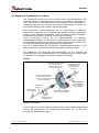
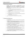
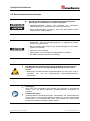
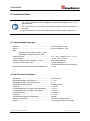
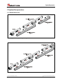
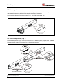
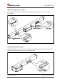
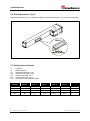
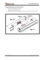
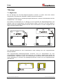
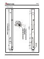
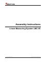
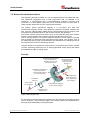
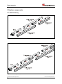
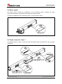
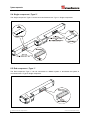
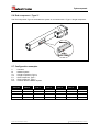
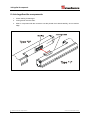
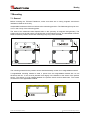
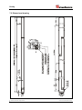
D Seite 2 - 22 GB Page 23 - 45 LMC-55 Kaskadierbares Linear-Mess-System LMC-55/ Cascadable Linear-Measuring-System LMC-55 • Grundlegende Sicherheitshinweise • Verwendungszweck • Allgemeine Funktionsbeschreibung • Mechanische Kenndaten • Montage • Basic safety instructions • Intended use • General functional description • Mechanical characteristics • Mounting TR - ELA - BA - DGB - 0013 - 03 / 03/30/2012 Montageanleitung / Assembly Instructions TR-Electronic GmbH D-78647 Trossingen Eglishalde 6 Tel.: (0049) 07425/228-0 Fax: (0049) 07425/228-33 E-mail: [email protected] http://www.tr-electronic.de Urheberrechtsschutz Dieses Handbuch, einschließlich den darin enthaltenen Abbildungen, ist urheberrechtlich geschützt. Drittanwendungen dieses Handbuchs, welche von den urheberrechtlichen Bestimmungen abweichen, sind verboten. Die Reproduktion, Übersetzung sowie die elektronische und fotografische Archivierung und Veränderung bedarf der schriftlichen Genehmigung durch den Hersteller. Zuwiderhandlungen verpflichten zu Schadenersatz. Änderungsvorbehalt Jegliche Änderungen, die dem technischen Fortschritt dienen, vorbehalten. Dokumenteninformation Ausgabe-/Rev.-Datum: Dokument-/Rev.-Nr.: Dateiname: Verfasser: 03/30/2012 TR - ELA - BA - DGB - 0013 - 03 TR-ELA-BA-DGB-0013-03.DOC MÜJ Schreibweisen Kursive oder fette Schreibweise steht für den Titel eines Dokuments oder wird zur Hervorhebung benutzt. Courier-Schrift zeigt Text an, der auf dem Display bzw. Bildschirm sichtbar ist und Menüauswahlen von Software. < > weist auf Tasten der Tastatur Ihres Computers hin (wie etwa <RETURN>). TR-Electronic GmbH 2009, All Rights Reserved Page 2 of 45 Printed in the Federal Republic of Germany TR - ELA - BA - DGB - 0013 - 03 03/30/2012 Inhaltsverzeichnis Inhaltsverzeichnis Inhaltsverzeichnis ............................................................................................................................ 3 Änderungs-Index .............................................................................................................................. 4 1 Allgemeines ................................................................................................................................... 5 1.1 Geltungsbereich .............................................................................................................. 5 1.2 Konformitätserklärung ..................................................................................................... 5 1.3 Zielgruppe ........................................................................................................................ 5 1.4 Verwendete Abkürzungen / Begriffe ................................................................................ 6 1.5 Allgemeine Funktionsbeschreibung ................................................................................ 7 2 Grundlegende Sicherheitshinweise ............................................................................................ 8 2.1 Symbol- und Hinweis-Definition ...................................................................................... 8 2.2 Verpflichtung des Betreibers vor der Inbetriebnahme ..................................................... 8 2.3 Allgemeine Gefahren bei der Verwendung des Produkts ............................................... 9 2.4 Bestimmungsgemäße Verwendung ................................................................................ 9 2.5 Bestimmungswidrige Verwendung .................................................................................. 9 2.6 Gewährleistung und Haftung ........................................................................................... 10 2.7 Organisatorische Maßnahmen ........................................................................................ 10 2.8 Personalauswahl und –qualifikation; grundsätzliche Pflichten........................................ 11 2.9 Sicherheitstechnische Hinweise ...................................................................................... 12 3 Transport / Lagerung .................................................................................................................... 13 4 Technische Daten .......................................................................................................................... 14 4.1 Umgebungsbedingungen ................................................................................................ 14 4.2 Mechanische Kenndaten ................................................................................................. 14 5 System-Komponenten .................................................................................................................. 15 5.1 Gesamtübersicht ............................................................................................................. 15 5.2 Master-System................................................................................................................. 16 5.3 Einzel-Komponente „Typ 1“ ............................................................................................. 16 5.4 Einzel-Komponente „Typ 2“ ............................................................................................. 17 5.5 End-Komponente „Typ 1“ ................................................................................................ 17 5.6 End-Komponente „Typ 2“ ................................................................................................ 18 5.7 Konfigurationsbeispiele ................................................................................................... 18 6 Zusammenfügen der Komponenten ............................................................................................ 19 7 Montage .......................................................................................................................................... 20 7.1 Allgemeines ..................................................................................................................... 20 7.2 Maßzeichnung ................................................................................................................. 21 8 Zubehör .......................................................................................................................................... 22 Printed in the Federal Republic of Germany 03/30/2012 TR-Electronic GmbH 2009, All Rights Reserved TR - ELA - BA - DGB - 0013 - 03 Page 3 of 45 Änderungs-Index Änderungs-Index Änderung Datum Index Erstausgabe 05.06.09 00 Linearitätsabweichung, bezogen auf die Messlänge: < 0,05 % auf < 0,02 % abgeändert 30.07.09 01 Anpassung der Warnhinweise 05.08.11 02 ESD-Schutzmaßnahmen aktualisiert; Bestimmungswidrige Verwendung 30.03.12 03 TR-Electronic GmbH 2009, All Rights Reserved Page 4 of 45 Printed in the Federal Republic of Germany TR - ELA - BA - DGB - 0013 - 03 03/30/2012 Allgemeines 1 Allgemeines Die vorliegende Montageanleitung ist im Lieferumfang enthalten und beinhaltet folgende Themen: Allgemeine Funktionsbeschreibung Grundlegende Sicherheitshinweise mit Angabe des Verwendungszwecks Mechanische Kenndaten Montage Da die Dokumentation modular aufgebaut ist, stellt diese Montageanleitung eine Ergänzung zu anderen Dokumentationen wie z.B. Produktdatenblätter, Maßzeichnungen, Prospekte und schnittstellenspezifische Benutzerhandbücher etc. dar. 1.1 Geltungsbereich Diese Montageanleitung gilt ausschließlich für die folgende Mess-System-Baureihe: LMC-55 Die Produkte sind durch aufgeklebte Typenschilder gekennzeichnet und sind Bestandteil einer Anlage. Es gelten somit zusammen folgende Dokumentationen: anlagenspezifische Betriebsanleitungen des Betreibers, diese Montageanleitung und das schnittstellenspezifische Benutzerhandbuch 1.2 Konformitätserklärung Die Mess-Systeme wurden unter Beachtung geltender europäischer bzw. internationaler Normen und Richtlinien entwickelt, konstruiert und gefertigt. Eine entsprechende Konformitätserklärung kann bei der Firma TR-Electronic GmbH angefordert werden. Der Hersteller der Produkte, die TR-Electronic GmbH in D-78647 Trossingen, besitzt ein zertifiziertes Qualitätssicherungssystem gemäß ISO 9001. 1.3 Zielgruppe Die vorliegende Dokumentation richtet sich an Montage- , Installations- und Inbetriebnahmepersonal, die das Mess-System LMC einsetzen Die entsprechende Qualifikation des Personals ist in Kapitel „Personalauswahl und – qualifikation; grundsätzliche Pflichten“, Seite 11 definiert. Printed in the Federal Republic of Germany 03/30/2012 TR-Electronic GmbH 2009, All Rights Reserved TR - ELA - BA - DGB - 0013 - 03 Page 5 of 45 Allgemeines 1.4 Verwendete Abkürzungen / Begriffe LMC Linear-Absolutes-Mess-System, Ausführung mit Profil-Gehäuse, kaskadierbar EG Europäische Gemeinschaft EMV Elektro-Magnetische-Verträglichkeit ESD Elektrostatische Entladung (Electro Static Discharge) IEC Internationale Elektrotechnische Kommission VDE Verein Deutscher Elektrotechniker TR-Electronic GmbH 2009, All Rights Reserved Page 6 of 45 Printed in the Federal Republic of Germany TR - ELA - BA - DGB - 0013 - 03 03/30/2012 Allgemeines 1.5 Allgemeine Funktionsbeschreibung Das Messprinzip basiert auf einer Laufzeitmessung (Ultraschallbereich). Die Ultraschall-Laufzeit ist wegproportional und wird in einer Elektronik ausgewertet. In einem Schutzrohr ist ein ferromagnetischer Draht (Magnetostriktives Messelement – Wellenleiter) gespannt, der mit einem Stromimpulse beaufschlagt wird. Durch den Stromimpuls entsteht um den Draht ein radiales Magnetfeld. Als Positionssensor (Permanet-Magnet) wird ein berührungslos zu führendes Magnetsystem verwendet, das ein magnetisches Längsfeld, bezogen auf den Draht, erzeugt. Treffen die beiden Magnetfelder, radial vom Draht und längs vom Magnet, am Messpunkt aufeinander, so wird ein Torsionsimpuls ausgelöst. Dieser Torsionsimpuls bewegt sich als Körperschallwelle mit konstanter Ultraschallgeschwindigkeit vom Messpunkt in beide Richtungen des Drahtes. Über einen Messwertaufnehmer im Sensorkopf wird das Ultraschall-Signal erfasst und in ein elektrisches wegproportionales Ausgangssignal umgewandelt. Die sich in beiden Richtungen bewegenden Körperschallwellen werden in den Dämpfungszonen am Anfang und Ende des Messelementes abgeschwächt. Die Zeitdifferenz vom Aussenden des Stromimpulses bis zum Eintreffen des Torsionsimpulses setzt die Messelektronik in ein wegproportionales Ausgangssignal um und stellt dies als digitales oder analoges Signal zur Verfügung. Prinzip Resultierendes Magnetfeld am Positionssensor / Resulting magnetic field at the position sensor Messwertaufnehmer Empfangsspule / Measuring sensor Receipt coil Magnetfeld, erzeugt durch einen Stromimpuls / Magnetic field, produced by a current impulse Antwortsignal des Torsionsimpulses / Answer signal of the torsion impulse Messdraht / Slide wire Stromimpuls / Current impulse Positionssensor (Magnet) / Position sensor (Magnet) Dämpfungszone / Damping zone Abbildung 1: Messtechnik Durch Anreihen von mehreren Mess-Systemen werden nahezu beliebige Messlängen erreicht. Die Messbereiche der Einzelsysteme überlappen sich, so dass eine durchgängige Messbarkeit entsteht. Printed in the Federal Republic of Germany 03/30/2012 TR-Electronic GmbH 2009, All Rights Reserved TR - ELA - BA - DGB - 0013 - 03 Page 7 of 45 Grundlegende Sicherheitshinweise 2 Grundlegende Sicherheitshinweise 2.1 Symbol- und Hinweis-Definition bedeutet, dass Tod oder schwere Körperverletzung eintreten kann, wenn die entsprechenden Vorsichtsmaßnahmen nicht getroffen werden. bedeutet, dass eine leichte Körperverletzung eintreten kann, wenn die entsprechenden Vorsichtsmaßnahmen nicht getroffen werden. bedeutet, dass ein Sachschaden eintreten kann, wenn die entsprechenden Vorsichtsmaßnahmen nicht getroffen werden. bezeichnet wichtige Informationen bzw. Merkmale und Anwendungstipps des verwendeten Produkts. bedeutet, dass entsprechende ESD-Schutzmaßnahmen nach DIN EN 61340-5-1 Beiblatt 1 zu beachten sind. 2.2 Verpflichtung des Betreibers vor der Inbetriebnahme Als elektronisches Gerät unterliegt das Mess-System den Vorschriften der EMVRichtlinie. Die Inbetriebnahme des Mess-Systems ist deshalb erst dann erlaubt, wenn festgestellt wurde, dass die Anlage/Maschine in die das Mess-System eingebaut werden soll, den Bestimmungen der EG-EMV-Richtlinie, den harmonisierten Normen, Europanormen oder den entsprechenden nationalen Normen entspricht. TR-Electronic GmbH 2009, All Rights Reserved Page 8 of 45 Printed in the Federal Republic of Germany TR - ELA - BA - DGB - 0013 - 03 03/30/2012 Grundlegende Sicherheitshinweise 2.3 Allgemeine Gefahren bei der Verwendung des Produkts Das Produkt, nachfolgend als Mess-System bezeichnet, ist nach dem Stand der Technik und den anerkannten sicherheitstechnischen Regeln gefertigt. Dennoch können bei nicht bestimmungsgemäßer Verwendung Gefahren für Leib und Leben des Benutzers oder Dritter bzw. Beeinträchtigungen des Mess-Systems und anderer Sachwerte entstehen! Mess-System nur in technisch einwandfreiem Zustand sowie bestimmungsgemäß, sicherheits- und gefahrenbewusst unter Beachtung dieser Montageanleitung und des schnittstellenspezifischen Benutzerhandbuchs verwenden! Insbesondere Störungen, die die Sicherheit beeinträchtigen können, umgehend beseitigen (lassen)! 2.4 Bestimmungsgemäße Verwendung Das Mess-System wird zur Erfassung von Linearbewegung sowie der Aufbereitung der Messdaten für eine nachgeschaltete Steuerung bei industriellen Prozess- und Steuerungs-Abläufen verwendet. Zur bestimmungsgemäßen Verwendung gehört auch: das Beachten aller Hinweise aus dieser Montageanleitung und dem schnittstellenspezifischen Benutzerhandbuch, das Beachten des Typenschildes und eventuell auf dem Mess-System angebrachte Verbots- bzw. Hinweisschilder, das Beachten der beigefügten Dokumentation wie z.B. Produktbegleitblatt, Steckerbelegungen etc., das Beachten der Betriebsanleitung des Maschinen- bzw. AnlagenHerstellers, das Betreiben des Mess-Systems innerhalb der in den technischen Daten angegebenen Grenzwerte (Montageanleitung/Benutzerhandbuch). 2.5 Bestimmungswidrige Verwendung Gefahr von Tod, Körperverletzung und Sachschaden durch bestimmungswidrige Verwendung des Mess-Systems ! Da das Mess-System kein Sicherheitsbauteil gemäß der EGMaschinenrichtlinie darstellt, muss durch die nachgeschaltete Steuerung eine Plausibilitätsprüfung der Mess-System-Werte durchgeführt werden. Das Mess-System ist vom Betreiber zwingend mit in das eigene Sicherheitskonzept einzubinden. Insbesondere ist folgende Verwendung untersagt: - in Umgebungen mit explosiver Atmosphäre. zu medizinischen Zwecken. Printed in the Federal Republic of Germany 03/30/2012 TR-Electronic GmbH 2009, All Rights Reserved TR - ELA - BA - DGB - 0013 - 03 Page 9 of 45 Grundlegende Sicherheitshinweise 2.6 Gewährleistung und Haftung Grundsätzlich gelten die "Allgemeinen Geschäftsbedingungen" der Firma TR-Electronic GmbH. Diese stehen dem Betreiber spätestens mit der Auftragsbestätigung bzw. mit dem Vertragsabschluss zur Verfügung. Gewährleistungs- und Haftungsansprüche bei Personen- und Sachschäden sind ausgeschlossen, wenn sie auf eine oder mehrere der folgenden Ursachen zurückzuführen sind: Nicht bestimmungsgemäße Verwendung des Mess-Systems. Unsachgemäße Montage, Installation, Inbetriebnahme und Programmierung des Mess-Systems. Unsachgemäß ausgeführte Arbeiten am Mess-System durch unqualifiziertes Personal. Betreiben des Mess-Systems bei technischen Defekten. Eigenmächtige vorgenommene mechanische oder elektrische Veränderungen am Mess-System. Eigenmächtige durchgeführte Reparaturen. Katastrophenfälle durch Fremdeinwirkung und höhere Gewalt. 2.7 Organisatorische Maßnahmen Die Montageanleitung muss ständig am Einsatzort des Mess-Systems griffbereit aufbewahrt werden. Ergänzend zur Montageanleitung/Benutzerhandbuch sind allgemeingültige gesetzliche und sonstige verbindliche Regelungen zur Unfallverhütung und zum Umweltschutz zu beachten und müssen vermittelt werden. Die jeweils gültigen nationalen, örtlichen und anlagenspezifischen Bestimmungen und Erfordernisse müssen beachtet und vermittelt werden. Der Betreiber hat die Verpflichtung, auf betriebliche Besonderheiten und Anforderungen an das Personal hinzuweisen. Das mit Tätigkeiten am Mess-System beauftragte Personal muss vor Arbeitsbeginn die Montageanleitung, insbesondere das Kapitel "Grundlegende Sicherheitshinweise", gelesen und verstanden haben. Das Typenschild, eventuell aufgeklebte Verbots- bzw. Hinweisschilder auf dem Mess-System müssen stets in lesbarem Zustand erhalten werden. Keine mechanischen oder elektrischen Veränderungen am Mess-System, außer den in dieser Montageanleitung ausdrücklich beschriebenen, vornehmen. Reparaturen dürfen nur vom Hersteller, oder einer vom Hersteller autorisierten Stelle bzw. Person vorgenommen werden. TR-Electronic GmbH 2009, All Rights Reserved Page 10 of 45 Printed in the Federal Republic of Germany TR - ELA - BA - DGB - 0013 - 03 03/30/2012 Grundlegende Sicherheitshinweise 2.8 Personalauswahl und –qualifikation; grundsätzliche Pflichten Alle Arbeiten am Mess-System dürfen nur von qualifiziertem Fachpersonal durchgeführt werden. Qualifiziertes Personal sind Personen, die auf Grund ihrer Ausbildung, Erfahrung und Unterweisung sowie ihrer Kenntnisse über einschlägige Normen, Bestimmungen, Unfallverhütungsvorschriften und Betriebsverhältnisse, von dem für die Sicherheit der Anlage Verantwortlichen berechtigt worden sind, die jeweils erforderlichen Tätigkeiten auszuführen, und dabei mögliche Gefahren erkennen und vermeiden können. Zur Definition von „Qualifiziertem Personal“ sind zusätzlich die Normen VDE 0105-100 und IEC 364 einzusehen (Bezugsquellen z.B. Beuth Verlag GmbH, VDE-Verlag GmbH). Klare Regelung der Verantwortlichkeiten für die Montage, Installation, Inbetriebnahme und Bedienung festlegen. Beaufsichtigungspflicht bei zu schulendem oder anzulernendem Personal ! Printed in the Federal Republic of Germany 03/30/2012 TR-Electronic GmbH 2009, All Rights Reserved TR - ELA - BA - DGB - 0013 - 03 Page 11 of 45 Grundlegende Sicherheitshinweise 2.9 Sicherheitstechnische Hinweise Zerstörung, Beschädigung bzw. Funktionsbeeinträchtigung des Mess-Systems und Gefahr von Körperverletzungen! Verdrahtungsarbeiten, Öffnen und Schließen von elektrischen Verbindungen nur im spannungslosen Zustand durchführen. Keine Schweißarbeiten vornehmen, wenn das Mess-System bereits verdrahtet bzw. eingeschaltet ist. Sicherstellen, dass die Montageumgebung vor aggressiven Medien (Säuren etc.) geschützt ist. Bei der Montage sind Schocks (z.B. Hammerschläge) auf das MessSystem zu vermeiden. Sensorrohr nicht verbiegen Mess-System nicht in die Nähe von Magnetfeldern montieren. Das Öffnen des Mess-Systems ist untersagt. Das Mess-System enthält elektrostatisch gefährdete Bauelemente und Baugruppen, die durch unsachgemäße Behandlung zerstört werden können. Berührungen der Mess-System-Anschlusskontakte mit den Fingern sind zu vermeiden, bzw. sind die entsprechenden ESD-Schutzmaßnahmen anzuwenden. Entsorgung Muss nach der Lebensdauer des Gerätes eine Entsorgung vorgenommen werden, sind die jeweils geltenden landesspezifischen Vorschriften zu beachten. Geräteausführungen Kundenspezifische Geräteausführungen, einschließlich der Anschlusstechnik, können sich von den hier beschriebenen Ausführungen in technischen Details unterscheiden. Im Zweifelsfall sollte daher unter Angabe der Artikelnummer Rücksprache mit dem Hersteller gehalten werden. TR-Electronic GmbH 2009, All Rights Reserved Page 12 of 45 Printed in the Federal Republic of Germany TR - ELA - BA - DGB - 0013 - 03 03/30/2012 Transport / Lagerung 3 Transport / Lagerung Transport – Hinweise Gerät nicht fallen lassen oder starken Schlägen aussetzen! Das Gerät enthält einen magnetoresistiven Sensor. Nur Original Verpackung verwenden! Unsachgemäßes Verpackungsmaterial kann beim Transport Schäden am Gerät verursachen. Lagerung Lagertemperatur : -30 bis +85°C Trocken lagern Printed in the Federal Republic of Germany 03/30/2012 TR-Electronic GmbH 2009, All Rights Reserved TR - ELA - BA - DGB - 0013 - 03 Page 13 of 45 Technische Daten 4 Technische Daten Die in den Technischen Daten angegebenen Informationen beziehen sich auf TRStandardgeräte. Das Typenschild und ein eventuell dem Gerät beigelegtes Datenblatt sind daher zu beachten ! Fehlende Abmaße sind aus den kundenspezifischen Zeichnungen zu entnehmen. 4.1 Umgebungsbedingungen Vibration ................................................................................... DIN EN 60068-2-6: 1996 Schock ..................................................................................... DIN EN 60068-2-27: 1995 EMV - Störaussendung, DIN EN 61000-6-3: 2007 - Störfestigkeit, DIN EN 61000-6-2: 2006 Arbeitstemperatur .................................................................... 0 °C…+70 °C, optional -20 °C…+70 °C Lagertemperatur ...................................................................... -30 °C…+85 °C, trocken Relative Luftfeuchte, DIN EN 60068-3-4: 2002 ..................... 98 %, keine Betauung Schutzart, DIN EN 60529: 1991 ............................................. IP 65, abhängig von der Steckerbelegung / Anschlusstechnik Magnetisches Störfeld, gemessen an der Messebene ......... < 3 mT 4.2 Mechanische Kenndaten Messprinzip.............................................................................. magnetostriktiv Messlänge Standard, Gesamtsystem .................................... 5…20 m Messlänge Standard, Einzel-Komponente ............................ 2 m Messlänge, End-Komponente ................................................ kundenspezifisch Auflösung ................................................................................. ≤ 0,05 mm Linearitätsabweichung, bezogen auf die Messlänge ............ < 0,02 % Linearitätsabweichung, bezogen auf ein Modul .................... ± 0,2 mm Reproduzierbarkeit .................................................................. ≤ 0,05 mm Hysterese................................................................................. ≤ 0,1 mm Verfahrgeschwindigkeit und Einbaulage ................................ beliebig Material - Mess-Körper............................................................ Aluminium Strangpressprofil Magnet ..................................................................................... Typ T1-S5520, andere auf Anfrage TR-Electronic GmbH 2009, All Rights Reserved Page 14 of 45 Printed in the Federal Republic of Germany TR - ELA - BA - DGB - 0013 - 03 03/30/2012 System-Komponenten 5 System-Komponenten 5.1 Gesamtübersicht Abbildung 2: „Minimal-Konfiguration, geradzahlig“ Abbildung 3: „Minimal-Konfiguration, ungeradzahlig“ Printed in the Federal Republic of Germany 03/30/2012 TR-Electronic GmbH 2009, All Rights Reserved TR - ELA - BA - DGB - 0013 - 03 Page 15 of 45 System-Komponenten 5.2 Master-System Das Master-System enthält die „Intelligenz“ des Mess-Systems, verwaltet die Einzel-Komponenten und bietet Anschlussmöglichkeiten für die jeweilige Ausgangs-Schnittstelle. Anschlussmöglichkeiten: Einzel-Komponente Typ 1, bzw. End-Komponente Typ 1 5.3 Einzel-Komponente „Typ 1“ Die Einzel-Komponente „Typ 1“ ist für den Anschluss an ein Master-System geeignet, bzw. bildet das Zwischenstück in Verbindung mit zwei „Typ 2“ Einzel-Komponenten. TR-Electronic GmbH 2009, All Rights Reserved Page 16 of 45 Printed in the Federal Republic of Germany TR - ELA - BA - DGB - 0013 - 03 03/30/2012 System-Komponenten 5.4 Einzel-Komponente „Typ 2“ Die Einzel-Komponente „Typ 2“ bildet das Zwischenstück in Verbindung mit zwei „Typ 1“ EinzelKomponenten. 5.5 End-Komponente „Typ 1“ Die End-Komponente „Typ 1“ ist für den Anschluss an ein Master-System geeignet, bzw. bildet das Endstück in Verbindung mit einer „Typ 2“ Einzel-Komponente. Printed in the Federal Republic of Germany 03/30/2012 TR-Electronic GmbH 2009, All Rights Reserved TR - ELA - BA - DGB - 0013 - 03 Page 17 of 45 System-Komponenten 5.6 End-Komponente „Typ 2“ Die End-Komponente „Typ 2“ bildet das Endstück in Verbindung mit einer „Typ 1“ Einzel-Komponente. 5.7 Konfigurationsbeispiele V M S-1 S-2 E-1 E-2 Pos = Variante = Master-System = Einzel-Komponente, Typ 1 = Einzel-Komponente, Typ 2 = End-Komponente, Typ 1 = End-Komponente, Typ 2 = Position nach dem Master-System Variante Master Pos 1 Pos 2 Pos 3 V1 M E-1 V2 M S-1 E-2 V3 M S-1 S-2 E-1 V4 M S-1 S-2 S-1 TR-Electronic GmbH 2009, All Rights Reserved Page 18 of 45 Pos 4 . . . E-2 Printed in the Federal Republic of Germany TR - ELA - BA - DGB - 0013 - 03 03/30/2012 Zusammenfügen der Komponenten 6 Zusammenfügen der Komponenten 1. Dichtung auf Beschädigungen überprüfen. 2. Fügeflächen müssen schmutzfrei sein. 3. Komponente mit dem Stecker sorgfältig und ohne zu verkanten auf die Platine aufschieben. Printed in the Federal Republic of Germany 03/30/2012 TR-Electronic GmbH 2009, All Rights Reserved TR - ELA - BA - DGB - 0013 - 03 Page 19 of 45 Montage 7 Montage 7.1 Allgemeines Bei der Montage des TR-Linear-Wegmess-Systems ist darauf zu achten, dass keine starken magnetischen und elektrischen Störfelder im Bereich des Sensors auftreten. Unzulässige Störfelder können die Messgenauigkeit beeinflussen. Im Bereich der Messebene darf die Feldstärke max. 3 mT betragen. Die Präzision der Messwerte ist u.a. abhängig von der Symmetrie der Magnetfeldgeometrie. Das bedeutet, dass der Positionssensor zum Mess-System präzise, axial und in der Höhe parallel zu führen ist. Der max. zulässige Abstand zwischen dem Positionssensor und dem Profilgehäuse darf dabei nicht überschritten werden: Das Befestigungsmaterial für den Positionssensor sollte unbedingt aus nicht magnetisierbarem Material bestehen. Wird magnetisierbares Befestigungsmaterial verwendet, muss ein Abstandshalter aus nicht magnetisierbarem Material mit 10 mm Dicke und min. 3 mm größer im Abstand zum Umfang des Positionssensors vorgesehen werden. Der Abstandshalter ist zwischen dem Positionssensor und dessen Befestigung zu montieren. Die Befestigungsschrauben müssen aus nicht magnetisierbarem Werkstoff sein. TR-Electronic GmbH 2009, All Rights Reserved Page 20 of 45 Printed in the Federal Republic of Germany TR - ELA - BA - DGB - 0013 - 03 03/30/2012 Montage 7.2 Maßzeichnung Printed in the Federal Republic of Germany 03/30/2012 TR-Electronic GmbH 2009, All Rights Reserved TR - ELA - BA - DGB - 0013 - 03 Page 21 of 45 Zubehör 8 Zubehör 490-00101 Info Schaltschrank -Modul PT-6 490-00105 TR-V-TI-D-0020 Info SchaltschrankModul PT-15/2 490-00310 TR-V-TI-D-0060 Info USB PC-Adapter V4 TR-E-TI-DGB-0074 490-01001 Software- und Support-DVD: - GSD-, EDS-, Typ- und XML-Dateien + Dokumentationen - Programmier-Software - Treiber 62-005-239 LMC Verbindungsstecker TR-Electronic GmbH 2009, All Rights Reserved Page 22 of 45 Printed in the Federal Republic of Germany TR - ELA - BA - DGB - 0013 - 03 03/30/2012 Assembly Instructions Linear-Measuring-System LMC-55 Printed in the Federal Republic of Germany 03/30/2012 TR-Electronic GmbH 2009, All Rights Reserved TR - ELA - BA - DGB - 0013 - 03 Page 23 of 45 TR-Electronic GmbH D-78647 Trossingen Eglishalde 6 Tel.: (0049) 07425/228-0 Fax: (0049) 07425/228-33 E-mail: [email protected] http://www.tr-electronic.de Copyright protection This Manual, including the illustrations contained therein, is subject to copyright protection. Use of this Manual by third parties in contravention of copyright regulations is forbidden. Reproduction, translation as well as electronic and photographic archiving and modification require the written content of the manufacturer. Offenders will be liable for damages. Subject to amendments Any technical changes that serve the purpose of technical progress, reserved. Document information Release date/Rev. date: Document rev. no.: File name: Author: 03/30/2012 TR - ELA - BA - DGB - 0013 - 03 TR-ELA-BA-DGB-0013-03.DOC MÜJ Font styles Italic or bold font styles are used for the title of a document or are used for highlighting. Courier font displays text, which is visible on the display or screen and software menu selections. < > indicates keys on your computer keyboard (such as <RETURN>). TR-Electronic GmbH 2009, All Rights Reserved Page 24 of 45 Printed in the Federal Republic of Germany TR - ELA - BA - DGB - 0013 - 03 03/30/2012 Contents Contents Inhaltsverzeichnis ............................................................................................................................ 3 Änderungs-Index .............................................................................................................................. 4 1 Allgemeines ................................................................................................................................... 5 1.1 Geltungsbereich .............................................................................................................. 5 1.2 Konformitätserklärung ..................................................................................................... 5 1.3 Zielgruppe ........................................................................................................................ 5 1.4 Verwendete Abkürzungen / Begriffe ................................................................................ 6 1.5 Allgemeine Funktionsbeschreibung ................................................................................ 7 2 Grundlegende Sicherheitshinweise ............................................................................................ 8 2.1 Symbol- und Hinweis-Definition ...................................................................................... 8 2.2 Verpflichtung des Betreibers vor der Inbetriebnahme ..................................................... 8 2.3 Allgemeine Gefahren bei der Verwendung des Produkts ............................................... 9 2.4 Bestimmungsgemäße Verwendung ................................................................................ 9 2.5 Bestimmungswidrige Verwendung .................................................................................. 9 2.6 Gewährleistung und Haftung ........................................................................................... 10 2.7 Organisatorische Maßnahmen ........................................................................................ 10 2.8 Personalauswahl und –qualifikation; grundsätzliche Pflichten........................................ 11 2.9 Sicherheitstechnische Hinweise ...................................................................................... 12 3 Transport / Lagerung .................................................................................................................... 13 4 Technische Daten .......................................................................................................................... 14 4.1 Umgebungsbedingungen ................................................................................................ 14 4.2 Mechanische Kenndaten ................................................................................................. 14 5 System-Komponenten .................................................................................................................. 15 5.1 Gesamtübersicht ............................................................................................................. 15 5.2 Master-System................................................................................................................. 16 5.3 Einzel-Komponente „Typ 1“ ............................................................................................. 16 5.4 Einzel-Komponente „Typ 2“ ............................................................................................. 17 5.5 End-Komponente „Typ 1“ ................................................................................................ 17 5.6 End-Komponente „Typ 2“ ................................................................................................ 18 5.7 Konfigurationsbeispiele ................................................................................................... 18 6 Zusammenfügen der Komponenten ............................................................................................ 19 7 Montage .......................................................................................................................................... 20 7.1 Allgemeines ..................................................................................................................... 20 7.2 Maßzeichnung ................................................................................................................. 21 8 Zubehör .......................................................................................................................................... 22 Contents ............................................................................................................................................ 25 Printed in the Federal Republic of Germany 03/30/2012 TR-Electronic GmbH 2009, All Rights Reserved TR - ELA - BA - DGB - 0013 - 03 Page 25 of 45 Contents Revision index .................................................................................................................................. 27 1 General information ...................................................................................................................... 28 1.1 Scope ............................................................................................................................... 28 1.2 Declaration of conformity ................................................................................................. 28 1.3 Target group .................................................................................................................... 28 1.4 Abbreviations and definitions........................................................................................... 29 1.5 General functional description ......................................................................................... 30 2 Basic safety instructions .............................................................................................................. 31 2.1 Definition of symbols and instructions ............................................................................. 31 2.2 Obligation of the operator before start-up ....................................................................... 31 2.3 General risks when using the product ............................................................................. 32 2.4 Intended use .................................................................................................................... 32 2.5 Non-intended use ............................................................................................................ 32 2.6 Warranty and liability ....................................................................................................... 33 2.7 Organizational measures................................................................................................. 33 2.8 Choice and qualifications of personnel; basic obligations ............................................... 34 2.9 Safety information’s ......................................................................................................... 35 3 Transportation / Storage ............................................................................................................... 36 4 Technical data................................................................................................................................ 37 4.1 Environmental conditions ................................................................................................ 37 4.2 Mechanical characteristics .............................................................................................. 37 5 System components ..................................................................................................................... 38 5.1 General survey ................................................................................................................ 38 5.2 Master system ................................................................................................................. 39 5.3 Single component „Type 1“ ............................................................................................. 39 5.4 Single component „Type 2“ ............................................................................................. 40 5.5 End component „Type 1“ ................................................................................................. 40 5.6 End component „Type 2“ ................................................................................................. 41 5.7 Configuration examples ................................................................................................... 41 6 Join together the components ..................................................................................................... 42 7 Mounting ........................................................................................................................................ 43 7.1 General ............................................................................................................................ 43 7.2 Dimensional drawing ....................................................................................................... 44 8 Accessories ................................................................................................................................... 45 TR-Electronic GmbH 2009, All Rights Reserved Page 26 of 45 Printed in the Federal Republic of Germany TR - ELA - BA - DGB - 0013 - 03 03/30/2012 Revision index Revision index Revision Date Index First release 06/05/09 00 Linearity deviation, related to the measuring length: < 0.05 % to < 0.02 % modified 07/30/09 01 Modification of the warnings 05/08/11 02 ESD-protective measures updated; Non-intended use 03/30/12 03 Printed in the Federal Republic of Germany 03/30/2012 TR-Electronic GmbH 2009, All Rights Reserved TR - ELA - BA - DGB - 0013 - 03 Page 27 of 45 General information 1 General information These Assembly Instructions are contained in the delivery package and include the following topics: General functional description Basic safety instructions with declaration of the intended use Mechanical characteristics Mounting As the documentation is arranged in a modular structure, this Assembly Instructions are supplementary to other documentation, such as product datasheets, dimensional drawings, leaflets and interface-specific User Manuals etc. 1.1 Scope These Assembly Instructions apply exclusively to the following measuring system model: LMC-55 The products are labeled with affixed nameplates and are components of a system. The following documentation therefore also applies: the operator's operating instructions specific to the system, these Assembly Instructions and the interface-specific User Manual 1.2 Declaration of conformity The measuring systems have been developed, designed and manufactured under observation of the applicable international and European standards and directives. A corresponding declaration of conformity can be requested from TR-Electronic GmbH. The manufacturer of the product, TR-Electronic GmbH in D-78647 Trossingen, operates a certified quality assurance system in accordance with ISO 9001. 1.3 Target group This documentation is directed towards Assembly, installation and commissioning personnel using the measuring system LMC The respective qualifications of the personnel are defined in Chapter “Choice and qualifications of personnel; basic obligations”, page 34. TR-Electronic GmbH 2009, All Rights Reserved Page 28 of 45 Printed in the Federal Republic of Germany TR - ELA - BA - DGB - 0013 - 03 03/30/2012 General information 1.4 Abbreviations and definitions LMC Linear-Absolute Measuring System, type with profile-housing, cascadable EC European Community EMC Electro Magnetic Compatibility ESD Electro Static Discharge IEC International Electrotechnical Commission VDE Verein Deutscher Elektrotechniker (German Electrotechnicians Association) Printed in the Federal Republic of Germany 03/30/2012 TR-Electronic GmbH 2009, All Rights Reserved TR - ELA - BA - DGB - 0013 - 03 Page 29 of 45 General information 1.5 General functional description The measuring principle is based on a run time measurement in the ultrasound area. The ultrasound propagation time is path proportional and is evaluated in an electronics. A ferromagnetic wire is (magnetostrictive measuring element shaft conductor) in a reed capsule tense, this one is pressurized with a current pulse. A radial magnetic field arises from the current pulse therefore. The position sensor (Permanent magnet) is a non-contact and wear free measurement magnetic system, which produces a magnetic axial field, related to the wire. If the two magnetic fields, radially from the wire and axial from the magnet, meet one another at the measuring point, then a torsion impulse will generated. This torsion impulse moves as acoustic wave of the measuring body with constant ultrasonic sound speed of the measuring point in both directions of the wire. Over a sensing element in the sensor head the ultrasonic sound signal is recorded and converted into electrical away-proportional output signal. The acoustic wave of the measuring body moving in both directions are weakened in the damping zones at the beginning and end of the measuring element. The time difference of sending the current pulse up to the arrival of the torsion impulse converts measuring electronics into an away-proportional output signal and makes this available as digital or analog signal. Principle Resultierendes Magnetfeld am Positionssensor / Resulting magnetic field at the position sensor Messwertaufnehmer Empfangsspule / Measuring sensor Receipt coil Magnetfeld, erzeugt durch einen Stromimpuls / Magnetic field, produced by a current impulse Antwortsignal des Torsionsimpulses / Answer signal of the torsion impulse Messdraht / Slide wire Stromimpuls / Current impulse Positionssensor (Magnet) / Position sensor (Magnet) Dämpfungszone / Damping zone Figure 1: Measuring technique By cascading of several measuring systems nearly all user-defined measuring lengths can be produced. The measuring ranges of the single systems are superposed, so that a general measurability can be guaranteed. TR-Electronic GmbH 2009, All Rights Reserved Page 30 of 45 Printed in the Federal Republic of Germany TR - ELA - BA - DGB - 0013 - 03 03/30/2012 Basic safety instructions 2 Basic safety instructions 2.1 Definition of symbols and instructions means that death or serious injury can occur if the required precautions are not met. means that minor injuries can occur if the required precautions are not met. means that damage to property can occur if the required precautions are not met. indicates important information or features and application tips for the product used. means that appropriate ESD-protective measures are to be considered according to DIN EN 61340-5-1 supplementary sheet 1. 2.2 Obligation of the operator before start-up As an electronic device the measuring system is subject to the regulations of the EMC Directive. It is therefore only permitted to start up the measuring system if it has been established that the system/machine into which the measuring system is to be fitted satisfies the provisions of the EC EMC Directive, the harmonized standards, European standards or the corresponding national standards. Printed in the Federal Republic of Germany 03/30/2012 TR-Electronic GmbH 2009, All Rights Reserved TR - ELA - BA - DGB - 0013 - 03 Page 31 of 45 Basic safety instructions 2.3 General risks when using the product The product, hereinafter referred to as "the measuring system", is manufactured according to state-of-the-art technology and accepted safety rules. Nevertheless, non-intended use can pose a danger to life and limb of the user or third parties, or lead to impairment of the measuring system or other property! Only use the measuring system in a technically faultless state, and only for its intended use, taking safety and hazard aspects into consideration, and observing these Assembly Instructions and the interface-specific User Manual! Faults which could threaten safety should be eliminated without delay! 2.4 Intended use The measuring system is used to measure linear movements and to condition the measurement data for the subsequent control of industrial control processes. Intended use also includes: observing all instructions in these Assembly Instructions and the interfacespecific User Manual, observing the nameplate and any prohibition or instruction symbols on the measuring system, observing the enclosed documentation, e.g. product insert, connector configurations etc. observing the manufacturer, operating instructions from the machine or system operating the measuring system within the limit values specified in the technical data (Assembly Instructions / User Manual) 2.5 Non-intended use Danger of death, physical injury and damage to property in case of nonintended use of the measuring system! As the measuring system does not constitute a safety component according to the EC machinery directive, a plausibility check of the measuring system values must be performed through the subsequent control system. It is mandatory for the operator to integrate the measuring system into his own safety concept. The following area of use is especially forbidden: - in environments where there is an explosive atmosphere. for medical purposes TR-Electronic GmbH 2009, All Rights Reserved Page 32 of 45 Printed in the Federal Republic of Germany TR - ELA - BA - DGB - 0013 - 03 03/30/2012 Basic safety instructions 2.6 Warranty and liability The General Terms and Conditions ("Allgemeine Geschäftsbedingungen") of TRElectronic GmbH always apply. These are available to the operator with the Order Confirmation or when the contract is concluded at the latest. Warranty and liability claims in the case of personal injury or damage to property are excluded if they result from one or more of the following causes: Non-intended use of the measuring system. Improper assembly, installation, start-up and programming of the measuring system. Incorrectly undertaken work on the measuring system by unqualified personnel. Operation of the measuring system with technical defects. Mechanical or electrical modifications to the measuring systems undertaken autonomously. Repairs carried out autonomously. Third party interference and Acts of God. 2.7 Organizational measures The Assembly Instructions must always be kept accessible at the place of use of the measuring system. In addition to the Assembly Instructions/User Manual, generally applicable legal and other binding accident prevention and environmental protection regulations are to be observed and must be mediated. The respective applicable national, local and system-specific provisions and requirements must be observed and mediated. The operator is obliged to inform personnel on special operating features and requirements. The personnel instructed to work with the measuring system must have read and understood the Assembly Instructions, especially the chapter “Basic safety instructions” prior to commencing work. The nameplate and any prohibition or instruction symbols applied on the measuring system must always be maintained in a legible state. Do not undertake any mechanical or electrical modifications on the measuring system, apart from those explicitly described in the Assembly Instructions. Repairs may only be undertaken by the manufacturer or a facility or person authorized by the manufacturer. Printed in the Federal Republic of Germany 03/30/2012 TR-Electronic GmbH 2009, All Rights Reserved TR - ELA - BA - DGB - 0013 - 03 Page 33 of 45 Basic safety instructions 2.8 Choice and qualifications of personnel; basic obligations All work on the measuring system must only be carried out by qualified personnel. Qualified personnel includes persons, who, through their training, experience and instruction, as well as their knowledge of the relevant standards, provisions, accident prevention regulations and operating conditions, have been authorized by the persons responsible for the system to carry out the required work and are able to recognize and avoid potential hazards. The definition of “qualified personnel” also includes an understanding of the standards VDE 0105-100 and IEC 364 (source: e.g. Beuth Verlag GmbH, VDE-Verlag GmbH). Clear rules relating to responsibilities for assembly, installation, commissioning and operation must be defined. There is an obligation to provide supervision for trainee personnel! TR-Electronic GmbH 2009, All Rights Reserved Page 34 of 45 Printed in the Federal Republic of Germany TR - ELA - BA - DGB - 0013 - 03 03/30/2012 Basic safety instructions 2.9 Safety information’s Destruction, damage or malfunctions of the measuring system ! De-energize the system before carrying out wiring work or opening and closing electrical connections. Do not carry out welding if the measuring system has already been wired up or is switched on. Ensure that the area around the assembly site is protected from corrosive media (acid, etc.). Avoid any shocks (e.g. hammer-blow) on the measuring system while mounting. Do not bend the sensor rod. Do not install the measuring system next to magnetic fields. Do not open the measuring system. The measuring system contains electrostatically endangered circuit elements and units which can be destroyed by an improper use. Contacts of the measuring system connection contacts with the fingers are to be avoided, or the appropriate ESD protective measures are to be applied. Disposal If disposal has to be undertaken after the life span of the device, the respective applicable country-specific regulations are to be observed. Device designs The technical details for customer-specific device designs, including connection technology, may differ from the designs described here. In case of doubt, the manufacturer should be consulted, specifying the item number. Printed in the Federal Republic of Germany 03/30/2012 TR-Electronic GmbH 2009, All Rights Reserved TR - ELA - BA - DGB - 0013 - 03 Page 35 of 45 Transportation / Storage 3 Transportation / Storage Notes on transportation Do not drop the device or expose it to strong strokes! Device contains a magnetoresistive sensor. Only use the original packaging! The wrong packaging material can cause damage to the device during transportation. Storage Storage temperature : -30 to +85°C Store in a dry place TR-Electronic GmbH 2009, All Rights Reserved Page 36 of 45 Printed in the Federal Republic of Germany TR - ELA - BA - DGB - 0013 - 03 03/30/2012 Technical data 4 Technical data The information specified in the Technical Data refers to the TR standard devices. The nameplate and any datasheet included with the device are therefore to be observed ! Missing dimensions are to be found in the customer-specific drawings. 4.1 Environmental conditions Vibration ................................................................................... DIN EN 60068-2-6: 1996 Shock ....................................................................................... DIN EN 60068-2-27: 1995 EMC - Transient emissions, DIN EN 61000-6-3: 2007 - Immunity to disturbance, DIN EN 61000-6-2: 2006 Working temperature............................................................... 0 °C…+70 °C, optional -20 °C…+70 °C Storage temperature ............................................................... -30 °C…+85 °C, dry Relative humidity, DIN EN 60068-3-4: 2002 .......................... 98 %, non condensing Protection class, DIN EN 60529: 1991................................... IP 65, dependent on the type of connector / connection technology Stray magnetic field, measured on the measuring level........ < 3 mT 4.2 Mechanical characteristics Measuring principle ................................................................. magnetostrictive Standard measuring length, complete system....................... 5…20 m Standard measuring length, Single component..................... 2 m Measuring length, End component......................................... customized Resolution ................................................................................ ≤ 0.05 mm Linearity deviation, related to the measuring length .............. < 0.02 % Linearity deviation, related to one module ............................. ± 0.2 mm Reproducibility ......................................................................... ≤ 0.05 mm Hysteresis ................................................................................ ≤ 0.1 mm Straight line velocity and mounting position ........................... no restrictions Material - measuring body ...................................................... Aluminium extruded profile Magnet ..................................................................................... T1-S5520, others upon request Printed in the Federal Republic of Germany 03/30/2012 TR-Electronic GmbH 2009, All Rights Reserved TR - ELA - BA - DGB - 0013 - 03 Page 37 of 45 System components 5 System components 5.1 General survey Figure 2: “Minimal configuration, even numbered” Figure 3: “Minimal configuration, uneven numbered” TR-Electronic GmbH 2009, All Rights Reserved Page 38 of 45 Printed in the Federal Republic of Germany TR - ELA - BA - DGB - 0013 - 03 03/30/2012 System components 5.2 Master system The master system contains the "Intelligence" of the measuring system, manages the single components and offers connectivities for the respective output interface. Connection possibilities: Single component Type 1 or End component Type 1 5.3 Single component „Type 1“ The Single component "Type 1" can be connected to a Master system or between two "Type 2" Single components. Printed in the Federal Republic of Germany 03/30/2012 TR-Electronic GmbH 2009, All Rights Reserved TR - ELA - BA - DGB - 0013 - 03 Page 39 of 45 System components 5.4 Single component „Type 2“ The Single component "Type 2" can be connected between two "Type 1" Single components. 5.5 End component „Type 1“ The End component "Type 1" can be connected to a Master system or terminates the system in connection with a "Type 2" Single component. TR-Electronic GmbH 2009, All Rights Reserved Page 40 of 45 Printed in the Federal Republic of Germany TR - ELA - BA - DGB - 0013 - 03 03/30/2012 System components 5.6 End component „Type 2“ The End component "Type 2" terminates the system in connection with a "Type 1" Single component. 5.7 Configuration examples V M S-1 S-2 E-1 E-2 Pos = Variants = Master System = Single component, Type 1 = Single component, Type 2 = End component, Type 1 = End component, Type 2 = Position after the Master System Variants Master Pos 1 Pos 2 Pos 3 V1 M E-1 V2 M S-1 E-2 V3 M S-1 S-2 E-1 V4 M S-1 S-2 S-1 Printed in the Federal Republic of Germany 03/30/2012 Pos 4 . . . E-2 TR-Electronic GmbH 2009, All Rights Reserved TR - ELA - BA - DGB - 0013 - 03 Page 41 of 45 Join together the components 6 Join together the components 1. Check sealing for damages. 2. Joining areas must be clean. 3. Slide on component with the connector onto the printed circuit board carefully, do not catch an edge. TR-Electronic GmbH 2009, All Rights Reserved Page 42 of 45 Printed in the Federal Republic of Germany TR - ELA - BA - DGB - 0013 - 03 03/30/2012 Mounting 7 Mounting 7.1 General Before mounting the TR-linear-Transducer, make sure there are no strong magnetic and electric interference fields in the vicinity. Inadmissible interference fields can influence the measuring precision. The field strength may be max. 3 mT in the vicinity of the measuring plane. The exact of the measured value depends also on the symmetry of magnetic field geometry. The position sensor must be led exactly in axial direction to the measuring body. The admissible maximum distance between position sensor and measuring body may not be exceeded: The mounting material for the position sensor should absolutely consist of not magnetizable material. If magnetizable mounting material is used, a spacer from not magnetizable material with 10 mm thickness and min. 3 mm must be planned more largely in the distance to the extent of the position sensor. The spacer is to be installed between the position sensor and its attachment. The screws must be from not magnetizable material. Printed in the Federal Republic of Germany 03/30/2012 TR-Electronic GmbH 2009, All Rights Reserved TR - ELA - BA - DGB - 0013 - 03 Page 43 of 45 Mounting 7.2 Dimensional drawing TR-Electronic GmbH 2009, All Rights Reserved Page 44 of 45 Printed in the Federal Republic of Germany TR - ELA - BA - DGB - 0013 - 03 03/30/2012 Accessories 8 Accessories 490-00101 Info Switch cabinet module PT-6 490-00105 TR-V-TI-GB-0020 Info Switch cabinet module PT-15/2 490-00310 TR-V-TI-GB-0060 Info USB PC-Adapter V4 TR-E-TI-DGB-0074 490-01001 Software- and Support-DVD: - GSD-, EDS-, Type- and XML-Files + Documentations - Programming Software - Driver 62-005-239 LMC connector plug Printed in the Federal Republic of Germany 03/30/2012 TR-Electronic GmbH 2009, All Rights Reserved TR - ELA - BA - DGB - 0013 - 03 Page 45 of 45