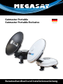
1
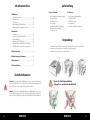
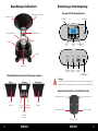
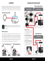
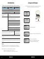
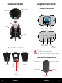
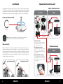
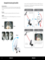
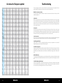
Brillantes Fernsehen Satmaster Portable Satmaster Portable Exclusive Deutsch Benutzerhandbuch und Installationsanleitung Inhaltsverzeichnis 1. Einführung Sicherheitshinweise.............................................................. 02 Lieferumfang............................................................................. 03 Verpackung................................................................................ 03 Bezeichnungen Außeneinheit....................................... 04 Bezeichnungen Stromeinspeisung............................. 05 2. Installation Installation.................................................................................. 06 Anschluss der Antenneneinheit................................... 07 Inbetriebnahme...................................................................... 08 Anzeigen des LCD Displays.............................................. 09 Beispiele für das Auffinden des Satelliten............... 10 Einstellwerte für europäische Hauptstädte........... 10 3. Fehlerbehebung.................................................................... 13 Lieferumfang Classic / Premium Professional • • • • • • • • • • • 1x Powersplitter (Stromeinspeisung) 1x Einspeisekabel 1x Reflektionshorn 1x Gummiring 1x USB zu Seriell Kabel (optional) 1x Netzteil (für Automobile) (12 V in / 24 V out) 1x Steuergerät inkl. Netzkabel 1x Einspeisekabel 1x Reflektionshorn 1x Gummiring 1x USB zu Seriell Kabel (optional) Verpackung 1. Entfernen Sie das Klebeband von der Verpackung (Verwenden Sie kein Messer) 2. Entnehmen Sie die Antenne vorsichtig aus der Verpackung 3. Entfernen Sie das Styropor von der Antenne. 4. Aktualisierung der Firmware...................................... 14 5. Ausleuchtzone......................................................................... 16 6. Technische Daten.................................................................. 17 Sicherheitshinweise Vorsicht - Unsachgemäße Handhabung kann zu schweren Schäden an diesem Gerät führen. Diese Person kann auch für daraus resultierende weitere Schäden am Gerät verantwortlich gemacht werden. ! Fassen Sie die Antenne nicht am „Spiegel“ an, sondern nur am Gehäuse! Hinweis – Lesen Sie das Benutzerhandbuch sorgfältig durch bevor Sie mit der Installation beginnen. Falls Sie schon ähnliche Produkte installiert haben, muss die Vorgehensweise mit diesem Produkt nicht übereinstimmen. 02 DEUTSCH DEUTSCH 03 Bezeichnungen Außeneinheit Polarisationsskala (Skew) Antennen Spiegel Bezeichnungen Stromeinspeisung Steuergerät für Professional Version LCD Display Netzschalter LNB Abdeckung Obere Endschalter UP DOWN SET Arm Kompass „Hoch“ Taste „Runter“ Taste BestätigungsTaste Saugfuß SETTOP ANT DATA DC12-24 V Bedienfeld Anschluss Anschluss Anschluss Receiver Antenne Service Ausgang Stromversorgung Die Bedienfelder der einzelnen Ausführungen variieren! Classic Premium Professional Achtung: Schließen Sie das Steuergerät immer über eine mit 5 Ampere abgesicherte, und mind. 2,5 mm² starke Leitung an (niemals direkt an die Auto Batterie). Stromeinspeisung für Classic und Premium Version keine Funktion „Hoch“ Taste zur Auswahl „Set“ Taste zur Bestätigung „Runter“ Taste zur Auswahl 04 DEUTSCH Antennenanschluss Receiveranschluss Betriebsanzeige LED DC Stromanschluss keine Funktion EIN/AUS Schalter DEUTSCH 05 Installation Befolgen Sie die nachfolgenden Anweisungen Schritt für Schritt, um Ihren Satmaster Portable problemlos alleine oder mit Hilfe eines Fachmannes zu montieren und anzuschließen. Bevor Sie mit dem Aufbau beginnen, überprüfen Sie bitte zunächst, ob alle gelisteten Teile enthalten sind. Sollte etwas fehlen, wenden Sie sich bitte an Ihren Händler. Anschluss der Antenneneinheit Classic / Premium Version Außenbereich FALSCH! Hinweis zum Anbau des LNB: Innenbereich RICHTIG! ANT SETTOP 24 Volt Receiver Gummiring STB Einspeisekabel Hinweis: Um den Kompass genau lesen zu können, bleiben Sie weg von großen Metallobjekten, insbesondere Elektrokabeln und nehmen mehrere Messungen vor. Einspeisekabel 12/24 V Spannungswandler TV 1. Antennenposition Wahl des Standortes Um ein Satellitensignal zu empfangen, muss der Satmaster Portable stets im Freien installiert und nach Süden ausgerichtet werden. Nutzen Sie zur groben Einstellung den integrierten Kompass am Gerät (Richten Sie sich nach den Azimuthwerten in der Tabelle am Ende des Handbuches). Vergewissern Sie sich, dass keine Hindernisse (Gebäude, Bäume, etc.) in Richtung Süden vor der Antenne liegen. Wenn Sie die Antenne montieren, suchen Sie nach einem gut zugänglichen, sicheren Standort. Überlegen Sie vorher, wo und wie Sie das Kabel zwischen Antenne und Receiver verlegen können. Gutes Empfangssignal Schlechtes Empfangssignal Platzieren Sie die Antenne mit freier Sicht zum Himmel. Vermeiden Sie feuchte Standorte. Die Antenne kann auf einem Sockel platziert werden. Professional Version 2. Grobe Ausrichtung der Antenne Drehen Sie das Antennengehäuse solange bis die Richtung des Zielsatelliten auf der Kompassanzeige mit dem Dreieck grob übereinstimmt. Innenbereich SETTOP 3. Polarisation (Skew Einstellung) Die Satellitenrichtung und der Polarisationswinkel des LNBs sind in jeder Region unterschiedlich und müssen manuell eingestellt werden (Siehe S. 12) SETTOP ANT DATA DC12-24 V Receiver ANT 12 V Anschlusskabel 06 DEUTSCH DEUTSCH TV 07 Inbetriebnahme Anzeige des LCD Displays Wählen Sie die für Ihre Ausführung zutreffende Spalte und folgen Sie den Anweisungen. Das LCD Display zeigt den aktuellen Status des automatischen Suchsystems. (nur bei Satmaster Portable Premium und Professional) CLASSIC PREMIUM PROFESSIONAL Schalten Sie TV und Receiver ein. Stellen Sie Ihren Receiver so ein, dass der gewählte Satellit (z.B. Astra 19,2° Ost) empfangen werden kann. Schalten Sie die Stromeinspeisung ein. Warten Sie, bis die Antenne Ihren Suchlauf und die Positionierung beendet hat. Schalten Sie das Steuergerät ein. Warten Sie 10 Sekunden um den automatischen Suchlauf mit der letzten Einstellung zu starten. Um die Einstellung zu ändern, drücken Sie eine beliebige Taste. Haben Sie eine Taste gedrückt, erscheint der Satellitenname auf dem LCD. Wenn nicht, sucht die Antenne nun den voreingestellten Satelliten und Sie können die nächsten 6 Schritte übergehen. Wählen Sie den gewünschten Satelliten mit den “hoch”- und “runter”-Tasten. ASTRA1 19.2E Beispiel (Satellitenauswahl) EL 30DEG Beispiel (Parkposition) Anschließend drücken Sie die “Set”-Taste um die Einstellung zu übernehmen. Ein paar Sekunden später erscheint das, “Elevationswinkel Menü” auf dem LCD. Wählen Sie eine passende Elevation mit den “hoch”- und “runter”-Tasten. Hinweis: Dies ist nicht zwingend erforderlich, jedoch beschleunigt es den Suchvorgang. Anschließend drücken Sie die “Set”-Taste um die Einstellung zu übernehmen. Beispiel (Elevationsauswahl) SIGNAL DETECTED Satellitensignal gefunden NIT DETECTED Bestätigt, dass das Signal des Zielsatelliten richitg ist SIGNAL LOST Kann kein Satellitensignal finden. Prüfen Sie die Ausrichtung der Antenne und die Einstellung des Polarisationswikels. Warten Sie, bis die Antenne Ihren Suchlauf und die Positionierung beendet hat. Nach erfolgter Inbetriebnahme müssen Sie die Stromversorgung abschalten, damit Sie alle TV-Programme problemlos empfangen können. Entfernen Sie nicht das Einspeisekabel zwischen Antenne und Receiver. Das Steuergerät schaltet sich selbstständig in den Standby. Sie können nun mit dem Netztschalter die komplette Stromzufuhr ausschalten. Jetzt startet der TV-Empfang automatisch und Sie empfangen ein TV-Signal. Sollten Sie kein Fernsehbild bekommen, prüfen Sie alle Verbindungen und Einstellungen (Receiver, Satmaster Portable und TV) und folgen den obigen Schritten noch einmal. Wenn Sie die Nutzung des Satmaster Portable beenden oder die Antenne zum Transport in die Parkposition bringen möchten, schalten Sie die Antenne an der Stromeinspeisung, bzw. am Steuergerät wieder ein und warten bis die Antenne in die Parkposition gefahren ist. Danach schalten Sie die Stromversorgung wieder aus und können die Antenne einpacken. Hinweis: Einige Satelliten steht eine Nord, bzw. Süd-Frequenz für die Suche zur Verfügung. Diese wählen Sie je nach dem, wo Sie sich gerade befinden (Nord- oder Südeuropa). Beispiel: Befinden Sie sich in Dänemark, wählen Sie Astra 1 Nord. Befinden Sie sich in Italien, wählen Sie Astra 1 Süd. Befinden Sie sich in Mitteleuropa, ist es gleich welchen Sie wählen. 08 DEUTSCH DEUTSCH 09 Beispiel für das Auffinden des Satelliten Polarisationswinkel (Skew) : Stellen Sie den entsprechenden Polarisationswinkel ein. Nutzen Sie hierzu die Skala auf der Rückseite der Antenne. Um den, für den jeweiligen Satelliten entsprechenden, Polarisationswinkel zu finden sehen Sie in der Tabelle auf Seite 12. Wenn Sie beispielsweise Canal+ über ASTRA1 (19.2 Ost) in Paris empfangen möchten, muss der Polarisationswinkel Skew bei -7.2, die Elevation bei 31.6, und Azimuth bei 158° liegen (Elevation und Azimuth stellen sich automatisch ein). Satelliten Position Elevation : Passen Sie den Elevationswinkel entsprechend der Tabelle am Ende des Handbuches an. Azimuth : Alle EU-relevanten Satelliten liegen im Süden. Der Azimuthwinkel vergrößert bzw. verkleinert sich von einem Satelliten zum nächsten. - Grad + Grad Azimuth Alle EU-relevanten Satelliten liegen im Süden. S E W N N W 158° vom geographischen Nordpol Elevation Astra 19,2° Ost Satmaster Portable E S Skew - Grad + Grad Elevation - 20° 0° + 20° 31,6° von der horizontalen Ebene 10 DEUTSCH Die Skala für Skew ist in 5er Schritte unterteilt, was der Toleranz für die Einstellung entspricht. Runden Sie also den Wert -7.2˚ auf -5° und stellen Sie den Zeiger entsprechend ein. DEUTSCH 11 Einstellungswerte für europäische Hauptstädte Fehlerbehebung Es gibt diverse Probleme, die das Empfangssignal und die Funktion des Satmaster Portable beeinträchtigen können. Der Folgende Abschnitt beschreibt diese Probleme und Möglichkeiten diese zu beheben. Defekte Sicherung, zu niedrige Spannungsversorgung, Kabelverbindung Wenn die Antenne bereits installiert ist, aber keine Funktion zeigt, gibt es drei Hauptfehlerquellen, die Sie bei der Fehlersuche zuerst überprüfen sollten: 1. Defekte Sicherung Sollte nach dem Einschalten die LED Leuchte der Stromeinspeisung nicht leuchten überprüfen Sie die Stromversorgung und die im Stecker, für den Zigarettenanzünder, befindliche 5 Ampere Sicherung. Der Stecker lässt sich an der Spitze aufschrauben. 2. Zu niedrige Spannungversorgung Ist das Verbindungskabel zu der Antenne länger als 15m, kann der Leitungswiderstand des Kabels die Spannungsversorgung der Antenne soweit absenken, dass ein störungsfreier Betrieb nicht mehr möglich ist. 3. Kabelverbindung Auch eine nicht ordnungsgemäße Kabelverbindung kann der Grund dafür sein, dass die Anlage nicht richtig funktioniert. Prüfen Sie alle Kabel und Steckverbindungen. Ausgebildetes Servicepersonal kann Ihnen behilflich sein. Kontaktieren Sie Ihren Megasat Fachhändler. 4. Unzureichendes Satellitensignal Vergewissern Sie sich, dass keine Hindernisse (Bäume, Gebäude, Dachüberstände, etc.) die Sicht auf den Satelliten versperren. Dies kann das Satellitensignal abschwächen oder blockieren. Auch durch Glas kann das Signal stark gedämpft werden. 5. Satellitenabdeckung Der Satmaster Portable bringt hervorragende Empfangsleistung in der Ausleuchtzone für 46 cm Antennen. Trotzdem kann das Signal in den Randzonen schwächer bis unzureichend sein. Erkundigen Sie sich ggf. im Internet nach der Ausleuchtzone des jeweiligen Satelliten. 6. Störungen durch Funk und Radar Die Abstrahlung von Funk und Radaranlagen kann zu einer Überlast an den Eingangsschaltkreisen der Antenne führen. Stellen Sie sicher, dass der Satmaster Portable nicht in unmittelbarer Nähe solcher Anlagen betrieben wird. 7. Frequenzdatenänderung der Satelliten Wenn die Antenne nicht in der Lage ist den Satelliten zu finden, kann es sein, dass sich die Frequenzdaten des Satelliten geändert haben. Diese Frequenzdaten können über den Wartungsanschluss aktualisiert werden. Kontaktieren Sie Ihren Megasat Händler, ob eine neue Firmware zur Verfügung steht. 12 DEUTSCH DEUTSCH 13 Aktualisierung der Firmware Aktualisierung bei CLASSIC und PREMIUM Aktualisierungsvorgang 1. Schalten Sie das Steuergerät, bzw. den Powersplitter aus und verbinden Sie den COM-Port des PCs mit der seriellen Schnittstelle. (Das Kabel muss RS-232 und “USB zu Seriell” unterstützen) 2. Starten Sie das DOWNLOAD Programm. Schließen Sie ein serielles Kabel an die Schnittstelle an 3. Wählen Sie den Pfad Ihrer Aktualisierungsdatei über “Open”. Aktualisierung bei PROFESSIONAL 4. Wählen Sie den COM-Prot Ihres Computers den Sie nutzen wollen und aktivieren sie diesen. Schließen Sie ein serielles Kabel an die Schnittstelle an 5. Schalten Sie das Steuergerät, bzw. die Stromeinspeisung ein. Der Download startet von selbst. SETTOP ANT DATA DC12-24 V Wenn die Antenne schon eingeschaltet ist, dann schalten Sie sie aus und wieder an, damit der Download startet. In ‘Com Port Select’ werden nur die Nummern der COM-Ports angezeigt, die genutzt werden können. Das Programm unterstützt Windows XP & 7. Kein Vista. 6. Nachdem der Download abgeschlossen ist, schalten Sie das Steuergerät, bzw. die Stromeinspeisung aus und ziehen das Datenkabel ab. 14 DEUTSCH DEUTSCH 15 Ausleuchtzone Technische Daten Antennen Typ LNB Typ Anzahl der Teilnehmer Frequenzband Eingangsfrequenzbereich Polarisation Signalverstärkung Minimum EIRP (Ausleuchtzone) Ausrichtungszeit Neigungswinkel (Elevation) Suchwinkel (Azimut) Motor Temperaturbereich Spannungsversorgung Durchmesser Spiegel Abmessungen (L/B/H) Gewicht Parabolantenne Universal Single LNB 1 Ku Band 10.7 GHz - 12.75 GHz V/H oder RHCP/LHCP 33 dBi 50 dBW ca. 1-2 min. 10° - 60° 180° 2-Achsen DC Motor -30 °C bis 80 °C 12 V DC 5 A / 24 V DC 2,5 A / 230 V (mit optionalen Netzteil) 46 cm 46 cm / 46 cm / 41 cm 7 kg Vorprogrammierte Satelliten: Classic: Astra 1 (19,2° Ost) Hinweis: In den Randgebieten der Ausleuchtzone kann es zu Empfangsstörungen kommen. Premium / Professional: Astra 1 (19,2° Ost), Astra 2 (28,2° Ost), Astra 3 (23,5° Ost), Astra 4 (4,8° Ost), Hotbird (13° Ost), Türksat (42° Ost), Thor (0,8° West), Hispasat (30° West), Eutelsat 5 West A (5° West), Eutelsat 9 A (9° Ost) Gewicht und Abmessungen sind nicht die absolut exakten Werte. Technische Details können jederzeit geändert werden (nach Hersteller) ohne vorherige Ankündigung. Konformitätserklärung Hiermit wird die Übereinstimmung mit folgenden Richtlinien/Normen bestätigt: Richtlinie zur elektromagnetischen Verträglichkeit 2004/108/EG EN 55013: 2001 + A1: 2003 + A2: 2006 EN 55020: 2007 EN 61000-3-2:2006 + A1:2009 + A2:2009 EN 61000-3-3:2008 Niederspannungsrichtlinie 2006/95/EG EN 60065: 2002 + A1: 2006 + A11: 2008 16 DEUTSCH DEUTSCH 17 Brillantes Fernsehen Satmaster Portable Satmaster Portable Exclusive English Stand: v3.1 Januar 2014 // Technische Änderungen, Druckfehler und Irrtümer vorbehalten. Megasat Werke GmbH | Industriestraße 4a | D-97618 Niederlauer | www.megasat.tv | [email protected] User manual and installation instructions Table of contents 1. Introduction Safety instructions................................................................. 02 Delivery......................................................................................... 03 Packaging.................................................................................... 03 Designations of outdoor unit......................................... 04 Designations of current injection................................ 05 2. Installation Installation.................................................................................. 06 Connecting the antenna unit......................................... 07 Startup.......................................................................................... 08 View the LCD display............................................................ 09 Examples for locating the satellite............................... 10 Set values for European capitals................................... 10 3. Troubleshooting.................................................................... 13 Delivery Classic / Premium Professional • • • • • • • • • • • • 1x Powersplitter (Current injection) 1x Supply cable 1x Reflection horn 1x Rubber ring 1x USB to Serial cable (optional) 1x Power supply (for vehicles) (12 V in / 24 V out) 1x Control unit 1x Supply cable 1x Reflection horn 1x Rubber ring 1x USB to Serial cable (optional) 1x Power supply (for vehicles) (12 V in / 24 V out) Packaging 1. Remove tape from packaging (Do not use knife) 2. Remove antenna gently from packaging 3. Remove Styrofoam parts from the antenna 4. Updating the Firmware.................................................... 14 5. Footprint...................................................................................... 16 6.Specifications............................................................................ 17 Safety Instructions Caution – Improper handling by unqualified personnel can cause serious damage to this equipment. Unqualified personnel who tamper with this equipment may be held liable for any resultant damage to the equipment. ! Do not handle antenna “dish”. Hold antenna by body “only”. Note – Before you begin, carefully read each of the procedures in this manual. If you have not performed similar operations on comparable equipment, do not attempt to perform these procedures. 02 ENGLISH ENGLISH 03 Designations of outdoor unit Polarization scale (Skew) Antennea dish Designations of current injection Control unit for Professional version LCD Display Power switch LNB Cover Upper limit UP DOWN SET Feed Compass „Up“ button „Down“ button Confirm button Suction cup SETTOP ANT DATA DC12-24 V Control panel Connection Connection Connection set-top box antenna Service Output power supply All panels are different for each package! Classic Premium Professional Warning: Connect the device only at a 5 amp protected line. The line must be at least 2.5 mm² strong. (never directly to the car battery). Current injection for Classic and Premium version no function „Up“ button for selection „Set“ button for confirm „Down“ button for selection 04 ENGLISH Antenna connection Set-top box connection Power indicator LED DC power supply no function ON/OFF switch ENGLISH 05 Installation Connection the antenna unit By following the instructions step by step you can proceed easily to install “Satmaster Portable” by yourself or with the help of a professional antenna installer. Before installing your antenna, you check that Satmaster Portable box contains all the items listedAbove in the ‘Box Contents’. In the event of any missing parts, please contact your distributor. Classic / Premium version Outdoor WRONG! Hinweis zum Anbau des LNB: Indoor RIGHT! ANT SETTOP 24 Volt Set-top box Gummiring STB Supply cable Supply cable Note: To read the compass right, stay away from large metal objects, especially electric cables and make several measurements. 12/24 V Power Inverter TV 1. Antenna location Place the antenna with a clear view of the sky. Avoid wet locations. The antenna can be placed on a base. Where to Install? Make sure that there are no obstacles in front of Satmaster Portable which can decrease the signal reception quality, such as buildings, or trees (you may keep in mind that trees will grow and may block the signal). In order to be able to fix and install your antenna easily you might choose an easily accessible place without any potential danger for installation. Think about the way you might pass your cable in a discreet way from the Satmaster Portable to your set-top box. good reception signal bad reception signal Professional version 2. Setting antenna irection Rotate the antenna housing until the direction of the target satellite on the compass display with the triangle coincides roughly. 3. Polarization (Skew settings) Indoor SETTOP The satellite direction and the angle of polarization of the LNB is different in each region and must be set manually (see page 12). SETTOP ANT DATA DC12-24 V Set-top box ANT 12 V connection cable 06 ENGLISH ENGLISH TV 07 Startup View the LCD Display Select the appropriate version for your column and follow the instructions. The LCD display shows the current status of the automated search system. (applies to Satmaster Portable Premium and Professional) CLASSIC PREMIUM PROFESSIONAL Turn on the TV and Settop box. Setting your set-top box, that you can receive the selected satellite (e.g. Astra 19,2° East) Turn on the power inserter Wait until the antenna has finished scanning and positioning. Turn on the control unit Wait 10 seconds for the automatic search with the last setting to start. To change the setting or to search manually, press any key within 10 seconds of any button on the control panel. Did you press a button, the satellite name appears on the LCD. If not, the antenna is now investigating the pre-satellite and you can skip the next 6 steps. Select the desired satellite using the „up“ - and „down“ buttons. ASTRA1 19.2E Sample (satellite selection) EL 30DEG Sample (Parkposition) Then press the „Set“ button to accept the setting. A few seconds later the „elevation angle menu“ on the LCD. Choose an appropriate elevation with the „up“ - and „down“ buttons. Note: This is not absolutely necessary, but it speeds up the search process. Then press the „Set“ button to accept the setting. Wait until your antenna has finished scanning and positioning. After commissioning, you must turn off the power supply so that you can receive all TV programs easily. Do not remove the input cable between antenna and receiver. The control unit switches off automatically to standby. You can now turn off complete the power supply with the power switch. After positioning is completed the TV reception is automatically started and you receive a TV signal. If you get no TV, check all connections and settings (Receiver, Portable and Satmaster TV) and follow the above steps again. If you want to stop using the Satmaster Portable or mount the antenna for transportation to the park position, turn on the antenna power supply and wait until the antenna is moved to park position. Then turn off the power again and can wrap the antenna. Note: Some Satellite IDs have north or south frequency for search. Please choose where you are currently (north or south). Sample (elevation selection) SIGNAL DETECTED Satellite signal is found NIT DETECTED Confirmed that the signal from the target satellite is correct SIGNAL LOST Can not find a satellite signal. Check the orientation of the antenna. Sample: If you are in Denmark, select Astra 1 North. If you are in Italy, select Astra 1 Süd. If you are in Central Europe, select Astra 1 North or South. 08 ENGLISH ENGLISH 09 Examples for locationg the satellite Polarisation (Skew) : Obtain the Skew Angle of the chosen satellite to tilt your antenna to the specified degree by looking to the degree graduation located on the back of the LNB skew degree controller. In order to watch Canal + through ASTRA1 (19.2 East) from the city ‘Brest’ of France, you will see Skew angle at -19.7, Elevation angle at 30, and Azimuth angle at 149.6 (Elevation and azimuth are automatically adjusted).. Satellite position Elevation : Adjust the elevation angle corresponding to the table at the end of the manual in. Azimuth : All EU-related satellites are in the south. The azimuth angle increases or decreases from one satellite to another. - Degree + Degree Azimuth All EU-related Satellites are located in the south. S E W N N W 158° from the geographic North Pole Elevation Astra 19,2° Ost Satmaster Portable E S Skew - Degree + Degree Elevation - 20° 0° + 20° 31.6 ° from the horizontal plane 10 ENGLISH The scale for skew is divided in 5 steps, which is the tolerance for the setting. So make the value of -7.2˚ to -5° and place the pointer. ENGLISH 11 Set values for European capitals Troubleshooting There are a number of common issues that can affect the signal reception quality or the operation of the Satmaster Portable. The following sections address these issues and potentialsolutions. Blown fuse, Low power, or wiring If the antenna unit is installed but entirely non-responsive, there are three key factors to check as part of the troubleshooting Process: 1. Blown fuse With the system powered on, move the antenna reflector slowly by hand. If the reflector does not move freely, a fuse is not the Problem. If the reflector does move freely, one of the two fuses mounted on the CPU Board may have blown or been broken. The Satmaster Portable Technical Manual Provides detailed instructions for authorized service personnel who may be required to replace a fuse. Contact your local Megasat dealer or service center for assistance. 2. Low power If the power cable to the antenna unit is more than 50ft (15 m), the power levels can decrease over the course of the cable, resulting in a voltage or current level at the antenna unit that is too low to power the system Properly. The Satmaster Portable Technical Manual Provides detailed instructions for supplying adequate power to the antenna unit. Contact your local Megasat dealer or service center for assistance. 3. Cable connection Also, an incorrect cable connection may be the reason that the system is not functioning properly. Check all cables and connections. Trained service personnel can assist you. Contact your Megasat dealer. 4. Satellite signal blocked Satellite signals can be blocked or degraded by buildings, other vessels, or equipment on the vessel itself. Simply moving the vessel or obstruction will clear the signal. 5. Satellite coverage issue Satmaster Portable will Provide outstanding reception within the 18” (46 cm) antenna coverage area for your satellite television service of choice. However, reception can be degraded as you apProach the fringe coverage areas. Refer to your satellite television service manual to check the viable coverage area for a18” (46 cm) antenna. 6. Radar interference The energy levels radiated by radar units can overload the antenna’s front-end circuits. Check with your installer to make certain that the Satmaster Portable antenna unit is in the optimal location with regard to your radar unit. 7. Satellite Frequency Data changed If some channels work while one or more other channels do not, or if the antenna is unable to find the satellite, the selected satellite’s frequency data may have changed. This frequency data can be updated via the maintenance port. Contact your local Megasat dealer or service center for assistance. 12 ENGLISH ENGLISH 13 Updating the firmware Updating CLASSIC and PREMIUM Update process 1. Turn off the control unit or the power splitter and connect the COM port of the PC with the serial interface. (The cable must be support RS-232, and „USB to Serial“) 2. Run the DOWNLOAD Program. Connect a serial cable to the interface 3. Select the path of your update file from „Open“. Updating PROFESSIONAL 4. Select the COM-Prot on your computer you wish to use and activate it. Connect a serial cable to the interface 5. Turn on the control unit or the power supply. The download will start by themselves SETTOP ANT DATA DC12-24 V If the antenna is already on, then turn it off and back on, so that the download starts. In ‚Com Port Select‘ Only numbers are displayed to the COM ports that can be used. The program supports Windows XP & 7th No Vista. 6. After the download is complete, turn off the control unit, or the power supply and disconnect the data cable. 14 ENGLISH ENGLISH 15 Footprint Specifications Antennea typ LNB typ Users Frequency band Frequency range Polarization LNB gain Minimum EIRP (Footprint) Search time Elevation Azimut Motor Operating temperature Power supply Dish diameter Dimensions (L/W/H) Weight Parabol antenna Universal Single LNB 1 Ku Band 10.7 GHz - 12.75 GHz V/H or RHCP/LHCP 33 dBi 50 dBW ca. 1-2 min. 10° - 60° 180° 2-Axis DC motor -30 °C to 80 °C 12 V DC 5 A / 24 V DC 2,5 A / 230 V (optional power supply) 46 cm 46 cm / 46 cm / 41 cm 7 kg Preprogrammed satellites: Classic: Astra 1 (19,2° Ost) Note: In the outlying areas of the footprint there may be interference. Premium / Professional: Astra 1 (19,2° East), Astra 2 (28,2° East), Astra 3 (23,5° East), Astra 4 (4,8° East), Hotbird (13° East), Türksat (42° East), Thor (0,8° West), Hispasat (30° West), Eutelsat 5 West A (5° West), Eutelsat 9 A (9° East) Weight and dimensions are not absolutely exact values. Technical details can be changed at any time (according to manufacturer) without prior notice. Declaration of Conformity This complies with the following directives / standards is confirmed: Electromagnetic Compatibility Directive 2004/108/EC EN 55013: 2001 + A1: 2003 + A2: 2006 EN 55020: 2007 EN 61000-3-2:2006 + A1:2009 + A2:2009 EN 61000-3-3:2008 Low Voltage Directive 2006/95/EG EN 60065: 2002 + A1: 2006 + A11: 2008 16 ENGLISH ENGLISH 17 Status: v3.1 January 2014 // Technical changes, misprint and errors reserved. Megasat Werke GmbH | Industriestraße 4a | D-97618 Niederlauer | www.megasat.tv | [email protected]