1
ENG_PS_Micro
10/1/01
12:13
Page 1
User Manual
Digital Paging System
PS6000
PS-Micro Control Desk
Pupitre de commande PS-Micro
PS-Micro Überwachungsstation
LBB 6105/00
Philips
Communication
Security & Imaging
ENG_PS_Micro
10/1/01
12:13
Page 2
ENG_PS_Micro
10/1/01
12:13
Page 3
English
User Manual
page 1
Français
Manuel de l'utilisateur
page 41
Deutsch
Benutzerhandbuch
Seite 81
ENG_PS_Micro
10/1/01
12:13
Page 4
ENG_PS_Micro
10/1/01
12:13
Page 1
PS-Micro control desk LBB 6105/00
ENGLISH
CONTENTS
1. INTRODUCTION . . . . . . . . . . . . . . . . . . . . . . . . . . . . . . . . . . . . . . . . . . . . . . . . . . . . . . . . . . .2
2. START-UP PROCEDURE . . . . . . . . . . . . . . . . . . . . . . . . . . . . . . . . . . . . . . . . . . . . . . . . . . . . . .7
3. STAND-BY MODE . . . . . . . . . . . . . . . . . . . . . . . . . . . . . . . . . . . . . . . . . . . . . . . . . . . . . . . . . .8
4. ALARM HANDLING PROCEDURES . . . . . . . . . . . . . . . . . . . . . . . . . . . . . . . . . . . . . . . . . .12
5. ALARM REROUTING . . . . . . . . . . . . . . . . . . . . . . . . . . . . . . . . . . . . . . . . . . . . . . . . . . . . . . .19
6. ERROR HANDLING PROCEDURESS . . . . . . . . . . . . . . . . . . . . . . . . . . . . . . . . . . . . . . . . . .22
7. LOGGING AND GUARD TOUR . . . . . . . . . . . . . . . . . . . . . . . . . . . . . . . . . . . . . . . . . . . . . .23
8. UNMANNED OPERATION . . . . . . . . . . . . . . . . . . . . . . . . . . . . . . . . . . . . . . . . . . . . . . . . . .25
9. GS HANDLING PROCEDURES . . . . . . . . . . . . . . . . . . . . . . . . . . . . . . . . . . . . . . . . . . . . . .27
10.SET-UP MENU . . . . . . . . . . . . . . . . . . . . . . . . . . . . . . . . . . . . . . . . . . . . . . . . . . . . . . . . . . . . .30
11. USER MENU . . . . . . . . . . . . . . . . . . . . . . . . . . . . . . . . . . . . . . . . . . . . . . . . . . . . . . . . . . . . . .31
12. SYSTEM MENU . . . . . . . . . . . . . . . . . . . . . . . . . . . . . . . . . . . . . . . . . . . . . . . . . . . . . . . . . . . .34
13.TEST MENU . . . . . . . . . . . . . . . . . . . . . . . . . . . . . . . . . . . . . . . . . . . . . . . . . . . . . . . . . . . . . .38
Terminology used in this Manual
1.
2.
The PS-Micro control desk throughout this manual will be termed as the control desk.
The PS-Micro mobile alarm transmitters LBB 6030 - LBB 6035 throughout this manual
will be termed as the PS-mobiles.
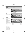
Symbols used in this Manual
Button press: When shown, press the relevant button once to perform the
action described. In some cases the button may have to be held for <2 or >2
seconds (this action will be stated).
Button press with options: When shown, press the relevant button to
perform the action described. The text shown below will show the options
available on the display when pressing this button in sequence.
OPTION
NOTE: This symbol is used to draw attention to special or additional
information.
Desk Loudspeaker: ON during described procedure
(see 4.7 Audible Bleep patterns)
Desk Loudspeaker: OFF during described procedure
1
ENG_PS_Micro
10/1/01
12:13
Page 2
PS-Micro control desk LBB 6105/00
User Manual
PS-Micro Control Desk
1.
INTRODUCTION
The personal security PS-Micro control desk type LBB 6105/00 in combination with PS-mobiles
(PS-Micro alarm transmitters LBB 603x/xx) has been installed in your organisation to provide a
fully integrated and effective Personal Security (PS) system.
1.1
PS-Micro control desk
At the heart of the personal security system is the control desk which constantly monitors all
operational PS-mobiles in your system (max.15 for a single desk). Each participant carries a
personal PS-mobile with an assigned unique identification address (Mobile-ID) and each PSmobile is assigned to a channel on the control desk.
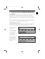
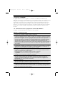
The control desk can be operated ‘manned or ‘unmanned’ by simply pressing a button. The
control desk includes 5 channel buttons (B1- B5) with their adjacent bi-colour (red/green) LED
indicators (see Fig. 1). Each button is assigned to a PS-mobile (Mobile-ID) in your system which
when pressed displays information on the desk’s display (Fig. 1(2)) according to the status of the
PS-mobile. Scrolling the PS-mobile channels is done using the ‘Main-button’ BM’ (Fig. 1(9)).
The control desk has two-modes of operation available for the user, ‘STAND-BY’ and ‘ALARMHANDLING’ (see Sections 3 and 4).
In the event of an alarm, the control desk informs its operator audibly through its loudspeaker
and visually through its bi-colour LED indicators and display. To handle the alarm the desk’s can
activate its in-built relay contacts (if programmed) to trigger an external alarm device, send
preprogrammed messages to dedicated pager holders (operator and colleague(s)) if a paging
system is installed, and send relevant alarm data to a connected printing device. But above all the
desk operator is made fully aware of the mobile holders situation whether the desk is manned
or unmanned.
1.2
Programming the desk
Intended for use by your system installer only, the programming of the control desk and the setup of the PS-mobiles are done using the PS-Micro utility software package running on a
temporary PC/Laptop computer.The control desk connects to the PC/Laptop using its built-in
RS232 interface.The RS232 interface can also be connected to a printer to print out a choice of
logged operator events and alarm actions (see Logging). A SET-UP menu on the control desk
allows the operator to select and set-up USER operational parameters and the installer to setup SYSTEM operational parameters, as well as performing a TEST procedure on the control
desk itself and if a paging system is connected the assigned pager can also be tested.
2
ENG_PS_Micro
10/1/01
12:13
Page 3
User Manual
PS-Micro control desk LBB 6105/00
Eng
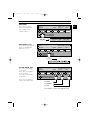
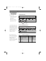
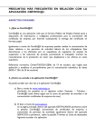
LBB 6105/00
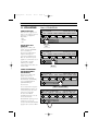
Rear view
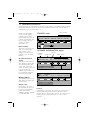
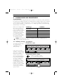
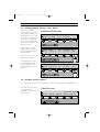
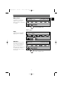
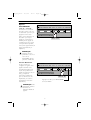
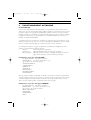
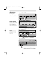
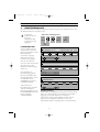
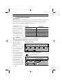
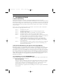
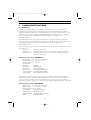
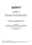
Key to symbols (Figure 1)
Loudspeaker
2 x 40 character LC-display
Channel-button (B1) with bi-colour LED indicator (L1) (red/green)
Channel-button (B2) with bi-colour LED indicator (L2) (red/green)
Channel-button (B3) with bi-colour LED indicator (L3) (red/green)
Channel-button (B4) with bi-colour LED indicator (L4) (red/green)
Channel-button (B5) with bi-colour LED indicator (L5)(red/green)
Main-button (BM) with 2 bi-colour LEDs (L6 (left) and L7 (right)) (red/green)
Telejack (RJ12) connector for RS232 connection to a remote PC or Printer.
16-pole Hirschmann connector for connection to the DP6000 line (connector-block).
6-pole DIN-type connector (female) for connection of the desks built-in relay
contacts (3x). For connection details refer to Installation Manual for the control desk.
Fig. 1 - PS-Micro control desk
3
ENG_PS_Micro
10/1/01
12:13
Page 4
PS-Micro control desk LBB 6105/00
1.3
User Manual
The PS-Micro mobile alarm transmitters
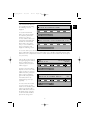
The PS-mobiles are programmed by your system installer to transmit periodic ‘check-in’ calls to
the control desk within a predefined ‘time-limit’ confirming that everything is OK. If no response
comes within this ‘time-limit’ an audible and visible alarm procedure is generated at the control
desk (technical-alarm). An alarm procedure can also be generated manually by the PS-mobile
holder pressing the ‘red’ alarm button on the PS-mobile, or automatically by the PS-mobile itself
when the ‘tear-off ’ plug has been removed, or under certain conditions, where prolonged
periods of ‘no-movement/not-vertical’ have been detected, or when the mobile is in a low
battery state. Each alarm procedure can be assigned a priority 1,2 or 3 programmable by your
system installer. Also included in the control desk are 3-programmable relay contacts, which
depending on how your systems has been set-up, can be used during an alarm procedure - to
activate an auto dialer for example.The auto dialer can be used to call out-side help.The relays
can also be used to set-off an external audible/visual alarm system or even to activate a 3rdparty paging system.
1.4
Check-in and Alarm calls
The PS-mobiles in your system are capable of transmitting two types of calls to the control desk,
‘Check-in’ scan calls and ‘Alarm’ calls.
1.4.1 ‘CHECK-IN’
scan calls
‘Check-in’ scan calls are silent
calls sent periodically to the
control desk to inform the
operator about the
operational status of the
mobile - such as ‘PRESENT’ ,
‘ABSENT’, or if the mobile’s
batteries are low and need
recharging ‘LOW BATTERY’.
The period between ‘checkin’ calls is defined by your
system installer and varies
depending on the number of
PS-mobiles used in the
system.
If the desk DOES NOT
receive a scan call within this
predefined time, a NOSCAN’ call alarm will be
raised, indicating to the
operator that this mobile is
technically not OK.
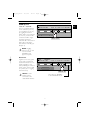
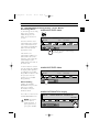
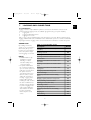
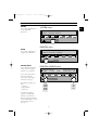
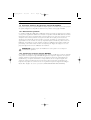
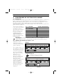
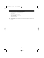
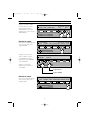
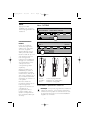
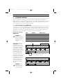
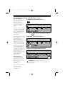
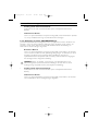
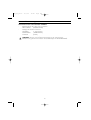
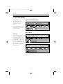
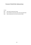
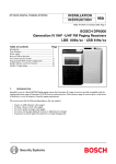
Type
Manual
alarm
Not-vertical/
No-move
alarm
Tear-off
alarm
Location
detection
LBB 6030
LBB 6031
LBB 6032
LBB 6033
LBB 6034
LBB 6035
Fig. 2 - PS-Micro Mobile alarm transmitter
(LBB 6030 - LBB 6035)
4
ENG_PS_Micro
10/1/01
12:13
Page 5
User Manual
PS-Micro control desk LBB 6105/00
1.4.2 ‘ALARM’ calls
‘Alarm’ calls to the control desk are initiated manually by the PS-mobile holder or automatically
by the PS-mobile itself. Manual alarms are initiated by pressing the red ‘manual’ alarm button on
the PS-mobile. Automatic alarm calls are generated by the mobile itself when in a motionless
/angled state for a prolonged period of time, or when the ‘tear-off ’ plug has been removed.
Figure 2 shows a PS-mobile with its ‘tear-off ’ plug and a table showing the range of PS-mobiles
and their functions.
1.5
Basic functions of the PS-Micro control desk
The control desk performs the following basic functions:
Table 1.1 Basic Functions
1. System Monitoring and Control
The control desk monitors the status of the PS-mobiles.
2. Alarm Processing
In the event of receiving an alarm from a PS-mobile holder , the control desk informs its
operator via audible and visual indications. Its built-in relay contacts can be activated, a
connected printer can be addressed to print out logging information (programmable) and
messages can be sent to assigned pagers (colleague and operator).
The operators display provides relevant information about the alarm-status, for example which PS-mobile raised the alarm, the type of alarm and the last two locations of the PSmobile, current and previous if location detection is available in your system.
3. Interfacing
The control desk can be interfaced using its built-in relay contacts, or connected to a PC
or printer using its RS232 interface or connected to a Philips Digital Paging DP6000
system.
4. Logging (see Table 7 Section 7.1)
The control desk if set-up for printing can log all calls and operator actions.
One of three logging modes can be programmed:
- Logging OFF (no logging)
- Log SELECT: only programmed logging events are printed
- Log ALL: All logging events are printed.
5. Guard Tour
In systems with location detection, the control desk can be set to print all location
information of selected PS-mobiles, even though logging is set to OFF for all other events.
6. GS Approval
If programmed for GS approval each PS-mobile must be tested by the operator every
time it is taken into operation and after 24 hours of constant use.
7. Programming
Using its RS232 connection, the control desk can be connected to a PC or Laptop
computer. Using the dedicated PS-Micro Utility software package the desk and PSmobiles/paging receivers can be programmed.
5
Eng
ENG_PS_Micro
10/1/01
12:13
Page 6
PS-Micro control desk LBB 6105/00
1.6
User Manual
Extended functions of the PS-Micro control desk
Systems can range from a simple personal security system, to systems incorporating both
location detection and DP6000 radio paging facilities.
1.6.1 Location detection
PS-mobiles type LBB 6031, LBB 6033 and LBB 6035 include a location detection module for use
where inductive location transmitters type LBB 6070 are installed.The location transmitters
transmit a location address (programmable) linked to the name of a location within your
organisation.This location address can be received by the PS-mobiles when passing location
transmitters.The location address information is then stored and sent during an ‘alarm-call‘ or
‘check-in’ call to the control desk, giving the operator the location of the PS-mobile holder. The
last two locations visited, current and previous are available.This feature is ideally suited for
directing ‘rescue’ teams to the location of the PS-mobile holder.
NOTE: Check with your system installer if location transmitters are installed.
1.6.2 DP6000 Paging facility
The functionality of the control desk can be extended with the addition of a Philips DP6000
paging system.The paging system includes paging receivers and a central paging transmitter.
During ‘unmanned’ operation an alarm can be automatically re-routed including its alarm
information to an assigned ‘Operator’s paging receiver. During ‘manned’ operation an alarm can
be ‘re-routed’ by the control desk operator to assigned ‘Colleague(s)’ paging receivers acting as a
rescue back-up team. (See 5 ALARM RE-ROUTING).
6
ENG_PS_Micro
10/1/01
12:13
Page 7
User Manual
2.
PS-Micro control desk LBB 6105/00
START UP PROCEDURE
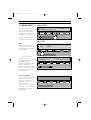
During start-up, once power is applied to the control desk, the desk performs a ‘START-UP’ test
procedure, where all its operational functions are checked.
Throughout this
document, the state of
the bi-colour LEDs
(red/green) are
indicated as shown.
Bi-colour LED Indications
OFF
G
R
ON
ON
G
R
Flashing Flashing
R = Red
G = Green
START-UP procedure
The display shows the
Software Version (SW) of
your desk and the ROM
CHECKSUM. During this
procedure the bi-colour
LEDs are illuminated, the
green first and then the red.
START UP PROCEDURE
SW VERSION
X.XX
G R
G
G
R
G R
G
Display test
After the LED test, the
control desk illuminates all
segments of its display.
G
R
ERROR LOGGING DEVICE
connect logging
device
R
G
R
R
Once the ‘START-UP’ is
complete, the control desk
emits two confirmation
bleeps before entering into
the ‘STAND- BY mode (see
3. STAND-BY MODE).
If a problem is encountered
by the control desk during
the ‘START-UP’ procedure
the control desk enters into
the ERROR HANDLING
mode (see 6 ERROR
HANDLING
PROCEDURES).
R
28-02-00 16:30
ROM CHECKSUM
XXXX
28-02-00 16:30
R
Peripheral check
After the ‘start-up procedure’, the control desk checks
peripheral connected to the system - such as a printer (logging
device) or a DP 6000 paging system. Any errors will be
displayed, and the loudspeaker will emit a ‘system-error’ bleep
(see 4.7 Audible bleep patterns).
.
7
Eng
ENG_PS_Micro
10/1/01
12:13
Page 8
PS-Micro control desk LBB 6105/00
3.
User Manual
STAND-BY MODE
In ‘STAND-BY’ mode (normal operational mode) the control desk monitors all operational PSmobiles made ‘active’ in the system. Each participants PS-mobile is assigned a MOBILE-ID
corresponding to its channel (max. 15 per control desk), shown on the display of the desk above
the corresponding channel button (B1 to B5).The date and time are shown on the upper line at
the right hand side of the display.
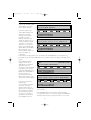
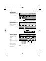
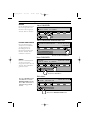
3.1 Mobile Identification (MOBILE-ID)
Depending on how your system has been installed, a PS-mobiles identification address (MobileID) can consist of up to 7 alphanumeric characters (max.) for example - the first name of the
holder, or the holders function within your organisation.The factory default setting is MOB 01 to
MOB 15.The table below gives an example of valid Mobile-IDs.The Mobile-Address shown
below is a 4-digit number programmed in the PS-mobile.
Example of valid
MOBILE-IDs.
NOTE: Throughout
this document the PSmobile IDs will be
shown as MOB 01 MOB 15 (default).
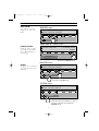
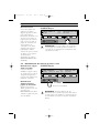
Desk in ‘STAND-BY’
mode showing 5 mobile IDs
(MOB 01 to MOB 05) above
their relevant channelbuttons. The bi-colour LED
of each active channel is ON
(green).
If more than five channels are
active press the <BM> key
(Fig.1(9)) to manually scroll
to the next set of channels,
or if programmed the display
will scroll automatically after
10 seconds to the next set
of active channels.
PS-Mobile
Mobile-ID
Mobile-Address
1
0001
0001
2
JOHN
0002
3
GUARD1
0003
4
TECHNIC
0004
5
STORES
0015
MOB 01
G
MOB 02
MOB 03
G
G
G
28-02-00 16:30
MOB 04 MOB 05
G
G
G
Press to scroll to next set of Mobiles
(max. 15)
MOB 06
NOTE: If not more
than 5-channels are
active, LED (L7) is OFF.
Date & Time
MOBILE ID
G
MOB 07
MOB 08
G
G
G
G
8
28-02-00 16:30
MOB 09 MOB 10
G
G
ENG_PS_Micro
10/1/01
12:13
Page 9
User Manual
PS-Micro control desk LBB 6105/00
Manually switching between channels is still possible, but after 10 seconds the desk switches back
to the group of channels which includes the alarm status. If more channels in different groups
have an alarm status the desk switches automatically between these groups. For channel
information on each Mobile (see 3.2. Mobile/Channel Information).
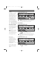
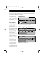
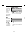
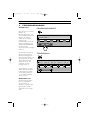
Table 3.1 Status of Channel LEDs in STAND-BY mode
Desk Status
Channel LED (L1- L5)
LC-display
Mobile in use, NO alarms
GREEN (steady)
Mobile ID
Mobile in use PRIORITY 3 alarm
RED (flashing)
Mobile ID
Mobile in storage rack
GREEN
Mobile ID (flashing)
Mobile de-activated
OFF
Blank
Table 3.2 Mobile status
Mobile status
Description
PRESENT
The PS-Mobile has reported itself ‘PRESENT’ to the system
and is in operational use.
WAIT FOR SCAN
The desk is waiting for a ‘check-in’ call from the
relevant PS-Mobile.The ‘check-in’ time is defined by your
system installer. If the desk does NOT receive a ‘checkin’ scan call within this time-frame’ an alarm procedure is
raised (see 4. ALARM HANDLING PROCEDURES).
ABSENT
The PS-mobile has been placed in to its
charging/storage rack
ALARM
The PS-mobile is in an alarm condition
(See 4. ALARM HANDLING PROCEDURES)
GS TEST
The PS-mobile is performing a GS Test procedure.
(See 9. GS HANDLING PROCEDURES).
LOW BATTERY
The PS-mobile is in ‘LOW BATTERY’ state.
9
Eng
ENG_PS_Micro
10/1/01
12:13
Page 10
PS-Micro control desk LBB 6105/00
User Manual
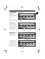
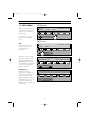
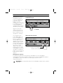
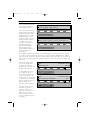
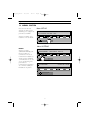
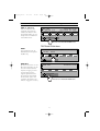
3.2 Mobile/Channel Information
By simply pressing the channel-button (B1- B5) corresponding to a particular mobile the display
will provide information about the status of a PS-mobile.The status of the channel LEDs in
‘STAND-BY’ mode are given in table 3.1.
While in the STAND-BY
mode, scroll through the
channels using the ‘mainbutton’ <BM> and press the
relevant channel-button (B1 B5) according to the PSmobile you require
information on
Date and Time
Shows the current date and
time. The format for the
Data and Time can be
changed according to your
preference (See 11. USER
MENU).
Channel Information
display
Once in the channel-information display, the display will
show the information and
status of the selected PSmobile. Its address, status, last
reported location (if
available) date and time and
the operational settings for
the selected PS-mobile.
MOB 01
G
MOB 02
MOB 03
G
G
G
28-02-00 16:30
MOB 04 MOB 05
G
G
G
CHANNEL INFORMATION display
MOBILEAddress
Location
Mobile status
USER options
0001
PRESENT
scan on guard
on RETURN
LOCATION 003
G
G
G
Mobile operational settings
0001
PRESENT
LOCATION 003
scan on guardoff
RETURN
Mobile address
G
The MOBILE address is a 4digit number programmed in
the PS-mobile.
Mobile status
Depending on the status of
the PS-mobile, its status can
be reported as: ‘PRESENT’,
‘WAIT FOR SCAN’,
‘ABSENT’, ‘ALARM’, ‘GSTEST’
or ‘LOW BATTERY’.
Date and Time
STANDBY mode
G
G
Table 3.2 gives an overview of the Mobile status.
location
If applicable to your system, the current reported location of
the PS-mobile during its last ‘check-in’ call. This location is
updated during a ‘check-in’ call or in some cases when the PSmobile passes a location transmitter. See 1.6.1 Location
detection.
10
ENG_PS_Micro
10/1/01
12:13
Page 11
User Manual
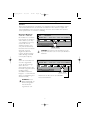
USER Options
‘scan on’ - ‘scan off ’
The ‘no scan-alarm’ function
can be activated (‘scan on’)
or not-activated (‘scan off ’)
by toggling the channelbutton <B3>. If not-activated
(i.e ‘not act’) is selected the
control desk will no longer
check this channel for
‘Check-in’ calls. However, if an
alarm call is received the
desk will react normally (see
Chapter 4).
PS-Micro control desk LBB 6105/00
0001
PRESENT
scan on guard
on RETURN
LOCATION 003
G
G
G
scan off
NOTE: Toggling
between ‘scan on’ and
‘scan off ’ is NOT
POSSIBLE in GS
approved systems.
Guard Tour
If guard tour is set to ‘guard
on’ the desk sends all new
location information of a PSmobile (regardless of its
status) including the selected
events of the chosen mobile
to a printer. (See 7 Logging
and Guard Tour).
0001
PRESENT
LOCATION 003
scan on guardoff
RETURN
G
G
G
guard on
NOTE: A serial
printer must be
connected to the
desks RS232 interface.
Press <B5> to ‘RETURN’
to the ‘STAND-BY’ mode
11
Eng
ENG_PS_Micro
10/1/01
12:13
Page 12
PS-Micro control desk LBB 6105/00
4.
User Manual
ALARM HANDLING PROCEDURES
4.1 Introduction
In the event of an alarm being activated by the PS-mobile or its holder, the control desk informs
its operator both audibly (loudspeaker) and visually (LEDs and display). Relays can be ‘energised’
or ‘not-energised’ to activate external devices - such as remote warning devices. Messages can
also be sent automatically to an assigned pager or to multiple pager holders and alarm handling
data information can be printed.
Alarms can be assigned with
three levels of priority (1, 2
and 3),The highest priority
being 1. Only alarms assigned
with priority 1 and 2 will
cause the desk to enter into
its ‘ALARM RECEIVED’
mode. For priority 3 alarms
the control desk remains in
‘its ‘’STANDBY MODE’.
ALARM type
PRIORITY
Manual alarm
Tear-off alarm
No-move alarm
Not-vertical alarm
Low battery alarm
No ‘Scan-call’ alarm
NOTE: The priority of the alarms are assigned by your system installer. Enter the
assigned priority in the table above.
4.2
Handling Priority 1 and 2 Alarms
The display opposite shows
the control desk in
‘STANDBY mode. (no
alarms present).
STAND-BY mode
MOB 01
G
In the event of an alarm
(priority 1 or 2) the control
desk emits an audible warble
bleep tone to alert its
operator and then enters
into its ‘ALARM-RECEIVED’
mode. In this mode LEDs
(L6 -L7) are flashing red.
The display shows the
MOBILE-ID, type of alarm
(e.g Manual Alarm) and the
location of the PS-mobile
holder. Press <B3> to toggle
and view the PS-mobiles
current (curr) and previous
(prev) locations.
MOB 02
G
G
28-02-00 16:30
MOB 04 MOB 05
MOB 03
G
G
G
G
ALARM RECEIVED Mode
Priority 1 or 2 alarm received
(see 4.7 Audible Bleep patterns)
MANUAL ALARM
MOB 01
curr
loc.
G
G
LOCATION 003
reroute
G
R
R
Flashing RED LEDs
12
prev
ENG_PS_Micro
10/1/01
12:13
Page 13
User Manual
4.3
PS-Micro control desk LBB 6105/00
Acknowledging incoming Priority 1 and 2 Alarms
Acknowledge Alarm
To acknowledge an incoming
alarm and to mute the
audible bleep press the
<BM> key for less than 2
seconds.
Once the alarm has been
acknowledged, the operator
of the control desk is now
responsible for handling the
alarm and must take the
appropriate action.
MANUAL ALARM
MOB 01
Alarm Handling
While in the ‘ALARM
RECEIVED’ mode press the
<B1> key to display
information on how to
handle the alarm.
Press <B5> to return to the
‘ALARM-RECEIVED’ mode.
NOTE: The information on how to
handle the alarm is
preprogrammed by
your system installer.
curr
loc.
G
G
LOCATION 003
reroute
G
R
R
Press <2 seconds to acknowledge
incoming alarm
If the alarm is not
acknowledged within a predefined ‘time-scale’ (max 9
mins) the control desk will
automatically stop the
audible alarm, but remain in
the alarm state.
If a new location is received
from the mobile (if available)
the display will be updated
accordingly and an audible
bleep will be emitted to alert
the operator of its new
location (see 4.7 Audible
bleep patterns).
Eng
ALARM RECEIVED Mode
ALARM RECEIVED Mode
MANUAL ALARM
MOB 01
curr
loc.
G
G
LOCATION 003
reroute
G
R
R
ALARM INFORMATION display
MOB 01
ALARM HANDLING INFORMATION
RETURN
G
R
R
13
ENG_PS_Micro
10/1/01
12:13
Page 14
PS-Micro control desk LBB 6105/00
Reroute
If a paging system is installed
press <B4> to reroute the
alarm information to an
assigned pager holder or to a
group of pager holders (see
Section 5.). If the control
desks in-built relay contacts
are programmed, an
incoming alarm can activate
external warning devices
such as sirens, indication
lamps or even an auto dialler
(see 5. ALARM REROUTING).
4.4
User Manual
ALARM RECEIVED mode
MANUAL ALARM
MOB 01
curr
loc.
G
G
LOCATION 003
reroute
G
R
R
NOTE: When an alarm is re-routed to a pager, new
locations (if available) will be sent to that pager as long
as the alarm is still active at the PS-mobile
Resetting Priority 1 and 2 Alarms
Reset Call from Mobile
On receipt of a reset call
from the mobile holder, or if
the holder placed the mobile
in to its charging/storage
rack, the control desk will
display ‘reseted’.
ALARM RECEIVED mode
MANUAL ALARM
MOB 01 reseted
G
G
LOCATION 003
reroute
G
R
R
Reset alarm at control
desk
Press the <BM> key (>2
secs) to ‘RESET’ the incoming
alarm.The desk returns to
the ‘ STAND-BY’ mode.
Force reset ?
If no alarm ‘reset’ was
received from the mobile
holder when the alarm was
reset by the desk operator,
the display allows the
operator to force reset
(‘FORCED RESET’) the alarm
(see opposite).
curr
loc.
> 2 secs
returns to STANDBY MODE
NOTE: If other alarms are active in the system these
alarms must be dealt with first before the desk enters in
to its STAND-BY mode. (see 4.5 Handling multiple
Alarms).
ALARM RECEIVED mode
MANUAL ALARM
MOB 01
curr
loc.
G
G
R
R
Press key <BM> for longer
than 2 seconds.The desk
displays the ‘Forced Reset ?’
option.
> 2 secs
14
LOCATION 003
reroute
G
ENG_PS_Micro
10/1/01
12:13
Page 15
User Manual
Pressing key <B4> (YES)
force resets the alarm and
returns the desk to its
normal ‘standby mode’.
Pressing key <B5> (NO) the
desk returns to its ‘Alarm
Received’ mode. If the
mobile while in alarm status
is still operational, it will
repeat its alarm until it is
reset at the PS-mobile. In this
state the desk will re-enter
the alarm status if such a
repeated alarm call has been
received.
PS-Micro control desk LBB 6105/00
FORCED RESET mode
Eng
28-02-00 16:30
YES
NO
FORCED RESET
?
G
G
R
R
returns to ‘STAND-BY’ mode
returns to ‘ALARM RECEIVED’ mode
Remote reset
The desk can also be programmed by the system installer so that an alarm is automatically reset
at the desk when a ‘reset-call’ is received from the mobile (the alarm has been reset at the PSmobile) or only if the mobile is placed in a storage/charging rack.
NOTE: Remote reset is not possible in GS approved systems
15
ENG_PS_Micro
10/1/01
12:13
Page 16
PS-Micro control desk LBB 6105/00
4.5
User Manual
Handling Multiple Priority 1 and 2 Alarms
In the event of multiple
incoming alarms, the control
desk, handles the alarms on a
priority basis (1,2 or 3) or if
the alarms are assigned the
same status (e.g Priority 1)
the control desk handles the
alarms on a ‘first-in-first-out’
(FIFO) procedure.
In the event of receiving
multiple alarms the control
desk automatically displays
the text ‘NEXT’.
ALARM RECEIVED mode
MANUAL ALARM
MOB 01 reseted
G
G
MANUAL ALARM
MOB 01 reseted
G
G
curr
loc.
LOCATION 003
reroute
NEXT
G
G
G
R
R
NO-MOVE ALARM
MOB 12 reseted
G
curr
loc.
G
LOCATION 003
reroute
NEXT
G
G
R
R
4.6
LOCATION 003
reroute
R
R
Press key <B5> to go to the
NEXT incoming alarm.
Handling the alarms is the
same as handling a single
incoming alarm (see 4.2
Handling priority 1 and 2
alarms).
curr
loc.
Handling Priority 3 Alarms
The control desk responds to incoming priority 3 alarms by remaining in the STANDBY mode.
The display opposite shows
the control desk in
‘STANDBY’ mode with no
alarms present.
STANDBY mode
MOB 01
G
MOB 02
MOB 03
G
G
G
G
16
28-02-00 16:30
MOB 04 MOB 05
G
G
ENG_PS_Micro
10/1/01
12:13
Page 17
User Manual
Priority 3 Alarm
When an alarm assigned
with priority 3 is activated by
a PS-mobile, the control desk
emits an audible priority 3
alarm (see bleep patterns),
and the associated LED of
the channel in alarm flashes
(red).
PS-Micro control desk LBB 6105/00
Priority 3 alarm received
(see 4.7 Audible Bleep patterns)
MOB 01
MOB 02
G
R
G
Reset
To reset a priority 3 alarm,
manually press the <B3>
key while the desk displays
the alarm in the information
window
G
28-02-00 16:30
MOB 04 MOB 05
G
G
G
Press the relevant key
associated with the alarm
(red flashing LED) to view
information about the alarm.
Priority 3 Alarm
Information
The display shows
information of a PS-mobile
with a priority 3 alarm..
MOB 03
Eng
Priority 3 Alarm (Mobile MOB 01)
(red flashing LED)
ALARM RECEIVED mode
0001
LOW BATTERY
LOCATION 003
RESET guard
onRETURN
G
NOTE: In GS approved systems a priority 3 alarm can
only be reset by placing the PS-mobile in its storage rack
or by de-activating the PS-mobile at the control desk.
17
ENG_PS_Micro
10/1/01
12:13
Page 18
PS-Micro control desk LBB 6105/00
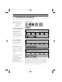
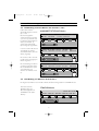
4.7
User Manual
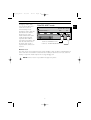
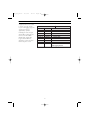
Audible bleep patterns
The diagram shown below gives a graphical view of the bleep patterns emmitted during the
operation the control desk.
Key to Audible bleeps
1. Reception of a ‘Priority 3’
alarm.
2. Reception of a Priority 1
and 2 alarm.
3. End of self test carried out
by the control desk.
Audible bleep patterns
High
1
Low
Off
200 ms
200 ms
Repeated until <BM>
key pressed
High
2
Low
Off
500 ms
500 ms
High
3
Low
Off
200 ms
4. System error (repeat until
Main button (BM) pressed)
200 ms
4
1900 ms
Low
Off
100 ms
5. Operator error (repeated 5
times)
6. New location received from
a PS-mobile in alarm mode.
Repeated
until <BM>
key pressed (>2 secs)
High
100 ms
High
5
Repeated 5 x
Low
Off
100 ms ON, 100 ms OFF
High
6
Low
Off
200 ms
7. Alarm ‘Not acknowledged’
(This signal is emitted when
switching to the next
received alarm in situations
where more than one alarm
is active).
7
200 ms
Repeated until acknowledged
by pressing <BM>
Low
Off
100 ms
=
Off
Low =
High =
18
400 ms
0 Hz
420 Hz
440 Hz
100 ms
ENG_PS_Micro
10/1/01
12:13
Page 19
User Manual
5.
PS-Micro control desk LBB 6105/00
ALARM REROUTING
Eng
5.1 Relay Handling
The control desk has 3 built-in relays which can be used to activate external warning devices,
such as a siren or even an auto-dialler to dial for external assistance.The relays in their stand-by
mode can be programmed to be ‘active’ (energised) or ‘in-active’ (de-energised). Active means
that the relay switches from its stand-by mode, and ‘in-active’ means the relay switches back to
its stand-by mode.
Relay 1 is always ‘active’ during an incoming alarm assigned as priority 1 or 2. Relays 2 and 3 can
be programmed as follows:
Mode
Mode
Mode
Mode
Mode
1.
2.
3.
4.
5.
Mode 6.
Mode 7.
The relay is ‘in-active’
The relay is ‘active’ for as long as the control desk emits an audible alarm.
The relay gives a pulse contact during a system error
The relay is continuously ‘active’ for as long as a system error is active.
The relay gives a pulse contact when the ‘Relay Reroute Delay Time’ expires
in ‘Unmanned’ mode. This functions is NOT available in ‘temporary
‘Unmanned’ mode.
The relay gives a pulse contact during a priority 1 or 2 alarm. Each time an
alarm is ‘re-routed’, the relay is activated.This function is suited for re-routing
alarms call in non DP6000 paging systems.
Same as Mode 6, but if a ‘field coverage call’ is received a pulse will also be
generated (this function can be used to perform a system site test).
5.2 Paging functions (for systems with paging functionality)
In systems including a paging system (central transmitter and paging receivers), the control desk
in the event of a priority 1 and 2 alarm can be programmed so the operator can ‘reroute’ an
alarm call including information to an assigned pager or to a group of pagers. Such pagers are
called ‘COLLEAGUE’ pagers’. Each channel of the control desk can be assigned to one ‘colleague’
pager. Re-routed paging calls to ‘colleague pagers can be repeated until the alarm is reset to
improve alarm operational handling procedures. Alarms calls can also be ‘re-routed’
automatically to an assigned desk ‘OPERATORS’ pager when the desk is set to ‘Temporary
Unmanned’ or ‘Unmanned’ operation.
5.2.1 Re-routing to OPERATOR pager
The modes for re-routing alarms calls to the pager of the control desk operator are as follows:
Manned operation
If set by your system installer, alarms assigned with priority 1 are ‘re-routed’ immediately
to the operator’s pager. Alarms assigned with priority 2 are only re-routed after a set
time (‘Re-route Delay Time’ (0 - 60 seconds)) and the alarm has not been acknowledged
(i.e. pressing the <BM> button at the control desk). Check this setting with your system
installer.
19
ENG_PS_Micro
10/1/01
12:13
Page 20
PS-Micro control desk LBB 6105/00
User Manual
-
Temporary unmanned operation
Acts similar to manned operation. (see also Chapter 8. Unmanned operation).
-
Unmanned operation
If set by your system installer, ALL alarms (priority 1, 2 and 3) are transferred immediately
to the ‘operator’s pager.
5.2.2 Re-routing to COLLEAGUE pager
Each operational channel of the control desk can be programmed to ‘re-route’ a priority 1 or 2
alarm to an assigned ‘colleague’ pager. Alarms assigned with priority 3 are NOT transferred.The
operational modes for re-routing alarms calls to a ‘colleague’ pager are as follows:
-
Manned operation
If set by your system installer, alarms assigned with priority 1 or 2 are re-routed to the
assigned ‘colleague’ pager after a set time (‘Re-route Delay Time’ (0 - 60 seconds)). Check
this setting with your system installer. However, the alarm call will not be re-routed if the
alarm call is acknowledged within the set time.
NOTE: When handling a priority 1 and 2 alarms, the control desk operator can always
‘re-route an alarm call to a ‘colleague’ pager manually by pressing the <B4> button (see
chapter 4.3 Reroute).
-
Temporary unmanned operation
Acts similar to manned operation. (see also Chapter 8. Unmanned operation).
-
Unmanned operation
If set by your system installer, alarms assigned with priority 1and 2 are re-routed
immediately to the ‘colleague’ pager.
20
ENG_PS_Micro
10/1/01
12:13
Page 21
User Manual
PS-Micro control desk LBB 6105/00
5.2.3 Applications
The following gives typical examples for relays programmed in different modes:
-
Acoustic indicator (Mode 2): Relay active for as long as the control desk is in the
‘ALARM-RECEIVED’ mode.
-
System error (Mode 3 and 4): Relay active if a system error occurs.The relay can be
pulsed (0.5 sec ON) or continuous when the relay is de-energised or when the error is
reset. For example - the relay can be used to inform a technician.
-
Auto dialler (Mode 5): Relay ‘active’ pulse contact for alarms assigned with priority 1
or 2. In ‘UNMANNED’ operation the relay is energised after the relay delay time, in
‘MANNED’ operation the relay is activated after ALARM-RECEIVED time-out. When
switching the desk from ‘MANNED’ to ‘UNMANNED’ operation the desk sees the autodialer function as if the desk is still manned for a set time (max. 20 minutes). This function
prevents a temporary ‘UNMANNED’ desk to immediately summon for outside help.
When the control desk operator leaves the ALARM-RECEIVED mode, the relay will not
be energised.
-
Alarm transfer (Mode 6): A relay which is programmed to operate in mode 6 can
be used to transfer an alarm to an external system.The relay will give a pulse everytime
an alarm reroute call to a colleague pager is activated.
21
Eng
ENG_PS_Micro
10/1/01
12:13
Page 22
PS-Micro control desk LBB 6105/00
6.
User Manual
ERROR HANDLING PROCEDURES
SYSTEM errors
If during normal operation
the control desk or its
peripherals (e.g. printer)
encounter a problem and do
not function correctly the
control desk automatically
enters into its’ ERROR
HANDLING’ mode and
displays information about
the error.
In the ERROR mode the
control desk emits an audible
bleep (see bleep patterns)
and the 2 LEDs associated
with the <BM> key are
flashing red.The channel keys
B1-B5 are disabled and their
associated LEDs are off.
Pressing the <BM> key (>2
secs) stops the audible error
bleep and returns the control
desk to its normal STANDBY
mode.
ERROR HANDLING mode
28-02-00 16:30
ERROR LOGGING DEVICE
connect logging
device
R
R
STAND-BY mode
MOB 01
G
MOB 02
MOB 03
G
G
G
G
OPERATOR errors
The control desk can be
programmed to emit an
audible operator error bleep
when a disabled key is
pressed.
22
28-02-00 16:30
MOB 04 MOB 05
G
G
ENG_PS_Micro
10/1/01
12:13
Page 23
User Manual
7.
PS-Micro control desk LBB 6105/00
LOGGING AND GUARD TOUR
Eng
7.1 Introduction
Logging of events is only available if a printer is connected to the RS232 connector of the
control desk.Three logging modes are available (programmed by your system installer):
1.
Logging OFF
2.
Logging of SELECTED events
3.
Logging of ALL events
Table 7.1 gives a list of available logging events (if logging is set to ALL, all items will be logged).
Logging of SELECTED events is intended for the control desk operator to evaluate events when
they happen whereas Logging of ALL events is intended for technicians to evaluate the system.
GUARD TOUR
By enabling a channel to
‘guard on’ (see 3.2 Channel /
Information) all reported
locations of a PS-mobile are
sent to the printer output
even if logging is set to OFF.
Table 7.1 List of logging events
NOTEs:
1. GUARD TOUR is only
applicable for system
including a location
detection facility and a
connected printer.
2. If a printer malfunctions
the control desk will store
up to 32 events (max.) and
print them out only when
the printer becomes
operational again. If more
than 32 events occurred
during this down-time a
message ‘ Logging device
inactive’ will be printed
including the date and time
the device malfunctioned.
Another message will then
be printed ‘Logging device
active again’ including the
date and time the device
became operational
followed by the stored
events.
Receiving a normal scan-call in the alarm mode
YES
Technical alarm
YES
Receiving a new location from a mobile in nonalarm status
NO
Receiving a new location from a mobile in alarm
status
YES
Receiving a new location from a mobile in field
coverage test
YES
Pressing any active button in any mode
NO
Alarm acknowledge
YES
Pressing any active button in alarm handling
mode
YES
Changing a system parameter in Set-up mode
NO
When performing a test in test mode
NO
Description
Default
Entering Stand-by mode after Power-up
(cold start)
YES
Receiving a scan call
NO
Receiving an alarm call
YES
Watchdog ‘time-out’ (warm start)
YES
Deactivating a mobile
YES
Occurring low priority system error
YES
Pressing any active button in error handling
mode
YES
Outgoing call
NO
Relay activating
YES
23
ENG_PS_Micro
10/1/01
12:13
Page 24
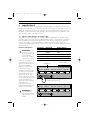
PS-Micro control desk LBB 6105/00
A typical print-out of events
is shown opposite. At the
top of each logging page, the
current operator (if
applicable) is printed
including the date and year
which will be printed in the
format set in the USER
MENU. Each logging line
begins with the time at
which the event took place
followed by the event.
User Manual
28-02-2000
11:24:04
11:24:14
11:24:15
11:24:20
11:24:24
12:34:16
12:45:04
12:51:23
13:12:03
14:34:54
PAUL
PAUL
PAUL
PAUL
GUARD1
1234
TECHNIC
GUARD1
24
---Manual alarm: location 003
Manual alarm: location 003
Audible alarm test
Reset manual alarm
Scan-call normal
location 004
Scan-call normal
Scan-call normal
location 005
system error in communication
with logging device
ENG_PS_Micro
10/1/01
12:13
Page 25
User Manual
8.
PS-Micro control desk LBB 6105/00
UNMANNED OPERATION
Eng
8.1 Introduction
During normal operation the control desk can be switched to an ‘Unmanned’ mode of
operation.This mode of operation allows the operator to leave the control desk while still being
able to receive alarm calls via the ‘OPERATORS’ pager. External warning devices connected to
the control desks built-in relays are also available. To set the control desk for UNMANNED
operation refer to Chapter 11. USER MENU.
When switching the control desk in to ‘Unmanned’ mode, the control desk first enter in to a
temporary ‘Unmanned’ mode.The duration of this mode is pre-defined by your system installer.
After the pre-defined duration the control desk then enters into its ‘Unmanned’ mode.
The information sent to the ‘Operators’ pager is defined by your system installer and consists of:
Address
Operator pager address
Bleep code:
The bleep code pattern which determines how the pager is called
(fixed value).
Numeric info:
Shown on the pager’s display (if applicable) the hours and minutes
the call was sent: e.g. HH:MM (fixed value).
Information received during an ALARM
Alphanumeric info: First 12 characters:
Alarm type: Second 12 characters
‘ALARM-PRIOx’
‘MAN. ALARM’
‘ TEAR-OFF’
‘NO-MOVE’
‘NOT-VERT’
‘TECH.ALARM’
‘LOW BATTERY’
‘ALARM RESET’
(x = priority 1 or 2)
In systems with location detection a call with 48-characters included is transmitted with the first
24-characters as described above and the second 24-characters describing the last location
visited. As long as the PS-mobile remains in alarm mode, each new location will be transmitted
directly to the reroute pager.
Information received during an ERROR call
Alphanumeric info: First 12 characters:
Error type: Second 12 characters:
25
‘ERROR-PRIOx’
‘LOG.DEVICE’
‘PAGINGLINE’
‘TALKBACKLINE’
‘RESET’
(x = priority 1 or 2)
ENG_PS_Micro
10/1/01
12:13
Page 26
PS-Micro control desk LBB 6105/00
User Manual
Information received during a change in STATUS
Alphanumeric info: First 12 characters:
‘NEW STATUS’
Status type: Second 12 characters
‘MANNED’ (* see Note)
‘UNMANNED’
‘STARTUP’
NOTE: See Chapter 11. USER MENU for a description of how to enter and operate the
control desk in ‘Unmanned’ mode.
26
ENG_PS_Micro
10/1/01
12:13
Page 27
User Manual
9.
PS-Micro control desk LBB 6105/00
GS (Geprüfte Sicherheit) HANDLING PROCEDURES
9.1 Introduction
In a GS (Geprüfte Sicherheit) approved system a PS-mobile and its associated equipment must
be tested every time a PS-mobile is taken into active duty (e.g when removed from its
charging/storage rack, or when batteries are replaced).The GS test procedure must also be
carried out (at least) within every 24 hours of continuous use. The control desk (if enable for
GS approved systems) has been set to perform this procedure after 23 hours of continuous
duty.
The GS test procedure is normally performed with both the PS-mobile holder and the control
desk operator (side-by-side). The GS test procedures must be performed for all alarms that
have been enabled (e.g No-Move, Not-Vertical and ‘Tear-off ’ alarms).
Performing the GS Test Procedure
The control desk detects that a PS-mobile has been removed from its storage/charging rack, its
23 hour duty timer has elapsed or when the PS-mobiles batteries have been changed. The
control desk indicates in its display that the GS test needs to be performed.
The display opposite shows
the control desk about to
begin the GS test.
- Press the ‘Manual’ Alarm
button on the PS-mobile
(>2 seconds). The PSmobile transmits the
‘Manual Alarm’ Call to the
control desk every 6
seconds until reset.
Once the call is received the
control desk displays the
screen opposite. To reset
the alarm call press the
‘Alarm/Reset’ button on the
PS-mobile again for < 2
seconds.
0001
ACTIVATE
MANUAL ALARM
28-02-00 16:30
NOTE: The Manual Alarm test is mandatory and must
always be tested in a GS approved system.
0001
28-02-00 16:30
Alarm
received,
reset
Manual
alarm
27
Eng
ENG_PS_Micro
10/1/01
12:13
Page 28
PS-Micro control desk LBB 6105/00
User Manual
If the ‘No-Move’ alarm has
been enabled for GS testing
the following screen is
displayed.
0001
ACTIVATE
NO-MOVE ALARM
To test the ‘No-Move’ alarm,
hold the PS-mobile in a
motionless and upright
position for at least 6
seconds. Wait until the alarm
tone is heard. The PS-mobile
will transmit the ‘No-Move’
Alarm Call every 6 seconds
to the control desk until
reset. Once received the
control desk displays the
following screen:
0001
28-02-00 16:30
Alarm
received,
reset
NO-MOVE
alarm
28-02-00 16:30
If the mobile is programmed in such away that ‘NO-MOVE’ can only become active is the
mobile is also in a ‘NOT-VERTICAL’ state, the PS-mobile should be kept motionless in a
horizontal position.
To reset the alarm press the PS-mobiles Alarm/Reset button (<2 seconds).The LED and bleep
confirmation will stop.The ‘No-move’ alarm reset call will be repeated every 6 seconds.
If the ‘Tear-off ’ alarm has
been enabled for GS testing,
the following screen is
displayed.
To test the ‘Tear-off Alarm’
remove the PS-mobiles
‘Tear-off ’ plug from its socket.
Wait until the alarm tone is
heard.The PS-mobile will
transmit the “Tear-off Alarm
Call” to the control desk
every 6 seconds until reset.
Once received, the control
desk displays the following
screen:
0001
28-02-00 16:30
ACTIVATE
TEAR-OUT ALARM 0001
28-02-00 16:30
Alarm
received,
reset
TEAR-OUT
alarm
To reset the ‘Tear-off alarm
call replace the ‘Tear-off ’ plug
onto its socket. The ‘Tear-off
reset call will be transmitted
every 6 seconds.
28
ENG_PS_Micro
10/1/01
12:13
Page 29
User Manual
If the ‘Not-Vertical’ alarm has
been enabled for GS testing
the following screen is
displayed.
To test the Not-Vertical
alarm, place the PS-mobile
in a stationary horizontal
position for at least 3
seconds until the alarm tone
is heard.The PS-mobile will
transmit the “Not-Vertical
Alarm Call” to the system
every 6 seconds until reset.
Once received, the desk
display the following screen:
PS-Micro control desk LBB 6105/00
0001
28-02-00 16:30
ACTIVATE
ALARM
NOT-VERTICAL
0001
28-02-00 16:30
Alarm
received,
reset
NO-VERTICAL
alarm
To reset the alarm press the Alarm/Reset button on the mobile (<2 seconds).The LED and
bleep confirmation will stop.The Not-vertical alarm reset call will be transmitted. When all the
alarms have been completed the PS-micro control desk shows the mobile is OK and ready for
use (see below).
If the mobile is placed into its
storage/charging rack without
having completed its test
sequence, the test sequence
will be stopped.
0001
MOBILE
IS
OK
The time-out for the Alarm
Requests is 60 seconds. If the
system receives no response
within these time periods, an
alarm sequence will start.
again. In this state place the
PS-mobile back into its
charging/storage rack (see
opposite).
0001
28-02-00 16:30
MOBILE
NOT
MOBILE
? YES
OK DISABLE
G
In a state where the mobile
can not be put in use, the
mobile can be disabled at the
desk by pressing the <B5>
button while the desk shows
the display shown opposite,
or the PS-mobile should be
placed in its storage rack..
R
G
R
29
28-02-00 16:30
RETURN
Eng
ENG_PS_Micro
10/1/01
12:13
Page 30
PS-Micro control desk LBB 6105/00
10. SET UP MENU
To enter the SET UP menu:
- ensure the desk is in the
‘stand-by’ mode (opposite).
- press and hold the <BM>
key for at least 2-seconds.
User Manual
STANDBY-mode
MOB 01
G
MOB 02
MOB 03
G
G
G
28-02-00 16:30
MOB 04 MOB 05
G
G
G
>2 secs
While in the SET UP mode
press <B1> to change USER
settings, <B2> to change
SYSTEM settings and <B3>
to enter the ‘TEST’ menu.
SET UP menu
SET UP
USER
SYSTEM
TEST
28-02-00 16:30
G
The choice of menu’s available
in the ‘SET UP’ menu enable
user functionality, system
parameters and tests to be
carried out.Table 10.1 lists the
menus available in the SET UP
menu.
Table 10.1 SET UP menu
USER (B1)
SYSTEM (B2)
TEST (B3)
B1
OFF - SELECT - ALL
REMOTE
SELF
B2
MANUAL - AUTO
PRINTER
PAGER
B3
UNMANN
B4
TIME
B5
DATE
30
CARD
ENG_PS_Micro
10/1/01
12:13
Page 31
User Manual
11. USER MENU
LOGGING
In the USER menu press
<B1> to toggle the options
available for Logging
- OFF
- SELECT
- ALL
For further information on
the above mentioned options
refer to Chapter 7.
CHANNEL VIEW
Press <B2> to select and
toggle between MANUAL
and AUTO mode. Select
‘Manual’ to manually scroll
through the channels when
the control desk is in
‘Standby’ status or ‘AUTO’ to
automatically scroll through
the active channels.
MANNED/UNMANNED
OPERATION
Press <B3> to select
between MANNED and
UNMANNED operation.
PS-Micro control desk LBB 6105/00
USER menu
Eng
MANUAL
UNMANN
28-02-00 16.30
TIME
DATE
MANUAL
UNMANN
28-02-00 16.30
TIME
DATE
MANNED
28-02-00 16.30
TIME
DATE
USER
OFF
G
SELECT
ALL
USER
OFF
G
AUTO
USER
SELECT
AUTO
G
UNMANNNED
If UNMANNED is selected
the control desk goes into a
temporary unmanned state.
After a pre-defined ‘ TIMEOUT’ period the desk enters
into a prolonged
UNMANNED OPERATION
state. To return to MANNED
operation press any key.
UNMANNED OPERATION
02 MOB 03
MOB 01 MOB
G
31
28-02-00 16.30
04 MOB
05
MOB
ENG_PS_Micro
10/1/01
12:13
Page 32
PS-Micro control desk LBB 6105/00
Press <B4> (YES) to return
to MANNED operation and
<B5> (NO) to remain in the
UNMANNED state.
User Manual
BACK TO MANNED
OPERATION
28-02-00 16:30
YES
NO
or
Returns to MANNED operation
(stand-by mode)
Remains to UNMANNED operation
SET TIME
In the USER menu press the
<B4> key to set the ‘TIME.
USER
OFF
MANUAL
UNMANN
28-02-00 16.30
TIME
DATE
G
Press <B1> sequentially to
set the HOUR and <B2>
sequentially to set the
MINUTES.
Press <BM> to return to the
USER menu
TIME
HOUR
28-02-00 16:30
MINUTE
G
Set Minutes
Set Hours
SET DATE
In the USER menu press the
key <B5> to set the DATE.
USER
OFF
MANUAL
G
32
UNMANN
28-02-00 16.30
TIME
DATE
ENG_PS_Micro
10/1/01
12:13
Page 33
User Manual
DATE FORMAT
Press <B1> to set the
format for displaying the
‘DAY’ ) (DD) and the
‘MONTH’ (MM).
PS-Micro control desk LBB 6105/00
DATE
MM/DD
/
YEAR
28-02-00 16:30
MONTH
DAY
R
28/02/00 16:30
DD/MM
DATE FORMAT (contd.)
Press <B2> key to select the
format for displaying the
‘DATE’ (i.e / or - ).
DATE
DD/MM
/
YEAR
02/28/00 16:30
MONTH
DAY
R
-
02-28-00 16:30
SET YEAR, MONTH, DATE
Press <B3> sequentially to
set the YEAR.
Press <B4> sequentially to
set the MONTH
Press <B5> sequentially to
set the DAY
Once set, press <BM> to
return to the USER menu
DATE
DD/MM
/
YEAR
02/28/00 16:30
MONTH
DAY
R
Set YEAR
Set MONTH
Set DAY
Press <BM> to return to the SET UP mode
33
Eng
ENG_PS_Micro
10/1/01
12:13
Page 34
PS-Micro control desk LBB 6105/00
User Manual
12. SYSTEM MENU
While in the SET-UP menu
press <B2> (SYSTEM) to set
the system parameters.
SET-UP menu
SET UP
USER
TEST
28-02-00 16:30
PRINTER
MOBILE
28-02-00 16:30
SYSTEM
Press <Bm> to return to the
STANDBY mode
G
SYSTEM menu
REMOTE
Press <B1> (REMOTE) to
place the control desk into
its remote mode.The
remote mode is used to
communicate with a PC for
downloading control desk
operational parameters set
by the system installer.
SYSTEM
REMOTE
G
REMOTE
G
Flashing
G
34
28-02-00 16:30
ENG_PS_Micro
10/1/01
12:13
Page 35
User Manual
PRINTER
Press <B2> (PRINTER) to
set the PRINTER
parameters.
PS-Micro control desk LBB 6105/00
SYSTEM menu
SYSTEM
REMOTE
Eng
PRINTER
MOBILE
28-02-00 16:30
G
PRINTER menu
CONFIG
Press <B1> (CONFIG) to
configure the PRINTER.
PRINTER
28-02-00 16:30
CONFIG PRINTSET
PAGETOP G
G
G
G
PRINTER CONFIG
In the PRINTER CONFIG
menu enter the settings
relevant to your printer.
Press <B1) repeatedly to
select the ‘Baudrate’.
Press <B5) repeatedly to
select ‘lines per page’.
The following settings are
fixed.
- 1 stopbit
- parity NONE
- 8 data bits
PRINTER CONFIG menu
PRINTER CONFIG
9600
1 STOP
G
NONE
28-02-00 16:30
8DATA 60LINE
G
G
30
33
60
66
300
1200
2400
4800
9600
The printer should be
capable of handling 80
characters per line and
always hardware handshake
is used (DTR/DSR) to check
if the logging device is
present.
35
ENG_PS_Micro
10/1/01
12:13
Page 36
PS-Micro control desk LBB 6105/00
PRINT SETTING
Press <B2> to send the
settings of the desk to the
printer.
User Manual
PRINTER menu
PRINTER
28-02-00 16:30
CONFIG PRINTSET
PAGETOP G
G
G
G
PRINTING SETTINGS menu
PRINTING SETTINGS
While the desk is sending
the settings to the printer,
press <B5> CANCEL to
stop printing.
PRINTING SETTINGS
28-02-00 16:30
CANCEL
G
To return to PRINTER menu
PRINTER menu
PAGETOP
If logging is to be continued
on a new page, press <B3>
PAGETOP.
PRINTER
28-02-00 16:30
CONFIG PRINTSET
PAGETOP G
G
G
G
To return to SYSTEM menu
SYSTEM menu
SYSTEM
REMOTE
PRINTER
MOBILE
28-02-00 16:30
G
To return to SET UP menu
In SET UP menu press <BM> for at least 2
seconds to return to the operational
STANDBY mode.
36
ENG_PS_Micro
10/1/01
12:13
Page 37
User Manual
MOBILE
Press <B3> (MOBILE) to
enter the PS-mobile
programming menu
PS-Micro control desk LBB 6105/00
SYSTEM menu
SYSTEM
REMOTE
Eng
PRINTER
MOBILE
28-02-00 16:30
G
MOBILE PROGRAMMING
At the left side of the display
the PS-mobile to be
programmed is shown. Press
<B1> repeatedly to scroll to
the PS-mobile to be
programmed.
PROGRAMMING MOBILE
MOB 1
28-02-00 16:30
START
G
Place the selected PS-mobile
in its Charging/storage rack
with its programming switch
(see opposite) set to the
‘programming mode’ (upper
position).
Press <B5> to ‘START’ the
programming procedure.The
desk will send the address
along with two operation
codes (Opcode 1 and 2) to
the selected PS-mobile via
the system data lines 1 and 2.
Once the PS-mobile has
been programmed, remove it
from its charging/storage rack
and set the programming
switch back to its original
state corresponding to the
type of batteries used (see
opposite).
1
2
3
Upper position
Middle position
Lower position
1 Programming mode
2 non-rechargeable batteries
3 rechargeable batteries
PS-mobile 3-position switch
NOTE: To program the PS-mobiles, the system data
lines 1 and 2 need to be connected between the
control desk and the storage racks. Refer to the
Installation Manual of the control desk.
37
ENG_PS_Micro
10/1/01
12:14
Page 38
PS-Micro control desk LBB 6105/00
13.TEST MENU
While in the SET-UP menu
press <B3> to perform a
self test of the control desk,
system pagers
Press <Bm> >2 sec. to
return to the STANDBY
mode
User Manual
SET-UP menu
SET UP
USER
SYSTEM
TEST
28-02-00 16:30
G
TEST menu
TEST
Press <B1> >2 seconds
(SELF) to put the desk
through a self test
procedure.
TEST
SELF
28-02-00 16:30
PAGER
G
During the ‘Test’ the display
shows the Software version
(SW), CHECKSUM of the
EPROM and the date and
time. All LEDs are tested first
red for 2 sconds and then
green for 2 seonds.
28-02-00 16:30
ROM CHECKSUM
003B
SELF TEST
SW VERSION X.XX
G R
G R
G R
G R
G R
G R
G R
LC-Display Test
During this ‘Test’ the
segments of the display are
tested. After the LED’s are
tested, all segments of the
display are illuminated to test
the display. At the end of the
test the desk will emit an
audible end of test signal (see
Chapter 4.8).
38
ENG_PS_Micro
10/1/01
12:14
Page 39
User Manual
END of self test
If the ‘SELF’ test is not
successful the control desk
will raise a system error
alarm and must be dealt with
accordingly.
PS-Micro control desk LBB 6105/00
SELF TEST
SW VERSION X.XX
28-02-00 16:30
ROM CHECKSUM
003B
G
To return to TEST menu
TEST menu
PAGER
(applicble only if a DP6000
paging system is installed).
TEST
SELF
PAGER
28-02-00 16:30
G
PAGER TEST
During this test, the control
desk will send a paging call
to the assigned ‘Operators’
pager.The alphanumeric
information sent with this call
is ‘HH:MM TEST’. Where
HH:MM is the time in hours
and minutes.
PAGER TEST
28-02-00 16:30
G
To return to TEST menu
39
Eng
ENG_PS_Micro
10/1/01
12:14
Page 40
PS-Micro control desk LBB 6105/00
User Manual
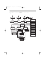
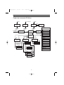
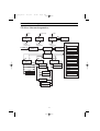
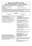
Operational overview of PS-Micro control desk
ERROR
GS_TEST REQUEST
ALARM
B1
System Error
Handling
GS Test
Procedure
Alarm
Handling
Alarm
information
B5
B5
Bm > 2 sec
Maintenance
Return to where
you came from
POWER ON
Return to where
you came from
Return to where
you came from
Bm
Start-up
Procedure
Bm > 2 sec
Talk-back monitor
Mobile
information
Stand-by
B1
Paging line
B1
B5
Bm > 2 sec
B5 + Bm > 2 sec
Set-Up
B1
Bm
B2
Bm
User
Set-Up
System
Set-Up
B1 Toggle log mode
B2 Toggle chain view
B1
B3
Self Test
Pager Test
Printer
Time
B1
Date
B2
B3
B5
B1
ROM Test
Bm
Print settings
B1
Default Set
B1
Top of page
Mobile
B1
Speaker Test
B1
Configuration
B3
Relay Test
Button Test
Bm
B5
B1
Bm
B2
B2
RS-232 Test
B1
B1
Remote
Line Monitor
B1
Bm
Test
Bm
B3 Toggle un/man
B4
Bm
Continues call
B1
Next Mobile
Program Mobile
40
Bm
FRE_PS_Micro
10/1/01
12:17
Page 41
Pupitre de commande PS-Micro LBB 6105/00
FRANÇAIS
SOMMAIRE
1. INTRODUCTION . . . . . . . . . . . . . . . . . . . . . . . . . . . . . . . . . . . . . . . . . . . . . . . . . . . . . . . . . .42
2. PROCÉDURE DE DÉMARRAGE . . . . . . . . . . . . . . . . . . . . . . . . . . . . . . . . . . . . . . . . . . . . . .47
3. MODE VEILLE . . . . . . . . . . . . . . . . . . . . . . . . . . . . . . . . . . . . . . . . . . . . . . . . . . . . . . . . . . . . .48
4. PROCÉDURES DE GESTION DES ALARMES . . . . . . . . . . . . . . . . . . . . . . . . . . . . . . . . . . .52
5. RÉACHEMINEMENT DES ALARMES . . . . . . . . . . . . . . . . . . . . . . . . . . . . . . . . . . . . . . . . . .59
6. PROCÉDURES DE GESTION DES ERREURS . . . . . . . . . . . . . . . . . . . . . . . . . . . . . . . . . . . .62
7. CONSIGNATION ET FONCTION GUARD TOUR . . . . . . . . . . . . . . . . . . . . . . . . . . . . . . .63
8. FONCTIONNEMENT AUTONOME . . . . . . . . . . . . . . . . . . . . . . . . . . . . . . . . . . . . . . . . . . .65
9. PROCÉDURES DE GESTION GS . . . . . . . . . . . . . . . . . . . . . . . . . . . . . . . . . . . . . . . . . . . . .67
10. MENU SET-UP . . . . . . . . . . . . . . . . . . . . . . . . . . . . . . . . . . . . . . . . . . . . . . . . . . . . . . . . . . . . .70
11. MENU UTILISATEUR . . . . . . . . . . . . . . . . . . . . . . . . . . . . . . . . . . . . . . . . . . . . . . . . . . . . . . .71
12. MENU SYSTEME . . . . . . . . . . . . . . . . . . . . . . . . . . . . . . . . . . . . . . . . . . . . . . . . . . . . . . . . . . .74
13. MENU TEST . . . . . . . . . . . . . . . . . . . . . . . . . . . . . . . . . . . . . . . . . . . . . . . . . . . . . . . . . . . . . .78
Terminologie utilisée dans ce manuel
1.
2.
Dans ce manuel, le pupitre de commande PS-Micro sera appelé pupitre de commande.
Dans ce manuel, les émetteurs d’alarmes mobiles LBB 6030 – LBB 6035 seront appelés
mobiles PS..
Symboles utilisée dans ce manuel
Bouton: Appuyez une fois sur le bouton correspondant pour exécuter l’action
décrite. Dans certains cas, vous devrez le maintenir enfoncé pendant plus ou
moins de 2 secondes (cela sera indiqué).
Bouton avec options: Appuyez sur le bouton correspondant pour exécuter
l’action décrite. Il vous suffira de réappuyer sur ce même bouton pour connaître
les options disponibles.
OPTION
REMARQUE : Ce symbole est utilisé pour attirer votre attention sur des
informations spéciales ou supplémentaires.
Haut-parleur du pupitre: ALLUMÉ lors de la procédure décrite
(cf. section 4.7, Signaux sonores).
Haut-parleur du pupitre: ÉTEINT lors de la procédure décrite.
41
FRE_PS_Micro
10/1/01
12:17
Page 42
PS-Micro control desk LBB 6105/00
User Manual
Pupitre de commande PS-Micro
1.
INTRODUCTION
Le pupitre de commande PS-Micro LBB 6105/00 et des mobiles PS (émetteurs d’alarmes PSMicro LBB 603x/xx) ont été installés au sein de votre entreprise en vue de vous faire bénéficier
d’un système de sécurité des personnes intégré et performant.
1.1
Pupitre de commande PS-Micro
Le pupitre de commande qui est au cœur de votre système de sécurité des personnes contrôle
en permanence tous les mobiles PS opérationnels de ce dernier (15 mobiles max. pour un
pupitre). Chaque utilisateur est équipé d’un mobile PS auquel sont affectés une adresse
d’identification unique (ID) et l’un des canaux du pupitre de commande.
Le pupitre de commande peut fonctionner de façon autonome ou non, sur simple pression d’un
bouton. Il intègre cinq boutons dédiés aux canaux (B1 – B5) assortis de témoins bicolores
(rouge/vert) (cf. fig. 1.) A chaque bouton correspond un mobile PS (ID) de votre système et
lorsque vous appuyez dessus, des informations sur l’état du mobile correspondant s’affiche sur
l’écran (fig. 1(2)) de votre pupitre de commande.Vous pouvez faire défiler les canaux des
mobiles PS au moyen du bouton principal ‘BM’ (fig. 1(9)).
Le pupitre de commande dispose de deux modes de fonctionnement : ‘STAND-BY’ et ‘ALARMHANDLING’ (cf. sections 3 et 4).
En cas d’alarme, le pupitre de commande en informe l’opérateur par le biais d’indicateurs
sonores (haut-parleur) et visuels (témoins bicolores et affichage). Pour traiter l’alarme, le pupitre
peut activer les contacts de relais qu’il intègre (sous réserve qu’ils soient programmés) en vue de
lancer un système d’alarme externe, d’envoyer des messages préprogrammés aux pagers
appropriés (opérateur et collègue(s)) si un système de réception d’appels est installé et
d’acheminer les informations sur l’alarme vers l’imprimante qui y est raccordée. Mais avant tout,
l’opérateur est tenu au courant de la situation de chacune des personnes utilisant un mobile, et
ce que le pupitre fonctionne en mode autonome ou non.
1.2
Programmation du pupitre
Seul l’installateur de votre système peut se charger de la programmation du pupitre de
commande et de la configuration des mobiles PS. Il exécute pour ce faire l’utilitaire PS-Micro sur
un PC/ordinateur portable temporaire. Le pupitre de commande se connecte au PC/portable au
moyen de son interface RS232 intégrée. Une imprimante peut également y être raccordée en
vue d’imprimer les événements et les alarmes consignés par l’opérateur (cf. Consignation). Enfin,
grâce au menu SET-UP du pupitre de commande, l’opérateur peut sélectionner et configurer les
paramètres de fonctionnement UTILISATEUR et l’installateur définir les paramètres de
fonctionnement du SYSTÈME, ainsi que TESTER le pupitre de commande et les pagers qui y
sont affectés, sous réserve qu’un système de réception d’appels soit installé.
42
FRE_PS_Micro
10/1/01
12:17
Manuel de l'utilisateur
Page 43
Pupitre de commande PS-Micro LBB 6105/00
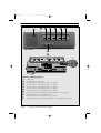
LBB 6105/00
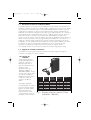
Legende des symboles (Fig 1)
Hautparleur
Affichage à cristaux liquides 2 lignes à 40 caractères
Channel-button (B1) with bi-colour LED indicator (L1) (rouge/vert)
Channel-button (B2) with bi-colour LED indicator (L2) (rouge/vert)
Channel-button (B3) with bi-colour LED indicator (L3) (rouge/vert)
Channel-button (B4) with bi-colour LED indicator (L4) (rouge/vert)
Channel-button (B5) with bi-colour LED indicator (L5) (rouge/vert)
Main-button (BM) with 2 bi-colour LEDs (L6 (left) and L7 (right)) (rouge/vert)
Telejack (RJ12) connector for RS232 connection to a remote PC or Printer.
16-pole Hirschmann connector for connection to the DP6000 line (connector-block).
6-pole DIN-type connector (female) for connection of the desks built-in relay
contacts (3x). For connection details refer to Installation Manual for the control desk.
Fig. 1 - Pupitre de commande PS-Micro
43
FRE_PS_Micro
10/1/01
12:17
Page 44
Pupitre de commande PS-Micro LBB 6105/00
1.3
Manuel de l'utilisateur
Émetteurs d’alarmes mobiles PS-Micro
Les mobiles PS-Micro sont programmés par l’installateur de votre système pour transmettre au
pupitre de commande des appels de contrôle réguliers confirmant que tout va bien. Si le pupitre
de commande ne reçoit aucune réponse dans le délai prédéfini, il émet une alarme sonore et
visuelle (alarme technique). Les alarmes peuvent également être générées manuellement par
l’utilisateur d’un mobile PS en appuyant sur le bouton ‘rouge’ dédié aux alarmes de ce dernier ou
automatiquement par le mobile PS lui-même dans les conditions suivantes : lorsque la fiche de
l’alarme dite ‘arrachée’ a été retirée, qu’une alarme dite ‘d’immobilité/non verticale’ a été
détectée ou que le niveau de charge des batteries du mobile est insuffisant. A chaque alarme est
affecté un niveau de priorité (1, 2 ou 3) programmable par l’installateur de votre système. Le
pupitre de commande intègre également trois contacts de relais programmables qui, selon la
configuration de votre système, peuvent être utilisés lors d’une procédure d’alarme pour activer,
par exemple, un système de numérotation automatique en vue de demander une aide
extérieure. Ces relais peuvent également servir pour éteindre un système d’alarme
sonore/visuelle externe ou pour activer une solution de réception d’appels tierce partie.
1.4
Appels de contrôle et d'alarme
Les mobiles PS de votre système peuvent transmettre deux types d’appels au pupitre de
commande : des appels de contrôle et d’alarme.
1.4.1 Appels de
contrôle
Il s’agit d’appels silencieux
envoyés périodiquement au
pupitre de commande
informant l’opérateur de
l’état de fonctionnement du
mobile au moyen
d’indications telles que :
‘PRESENT’, ‘ABSENT’ ou
‘BATTERIES FAIBLES’ . Le laps
de temps entre chaque appel
de contrôle est défini par
l’installateur de votre système
et varie en fonction du
nombre de mobiles PS
utilisés.
Type
Alarme
Manuelle
Alarme
Verticalite/
Immobilité
Alarme
Arrachement
Localisation
LBB 6030
LBB 6031
Si le pupitre d’appel NE
reçoit PAS l’appel de contrôle
prévu dans le temps imparti,
il génère une alarme ‘NONSCAN’, informant ainsi
l’opérateur que le mobile
correspondant rencontre des
problèmes d’ordre technique.
LBB 6032
LBB 6033
LBB 6034
LBB 6035
Fig. 2 - Émetteur d’alarmes mobile PS-Micro
(LBB 6030 - LBB 6035)
44
FRE_PS_Micro
10/1/01
12:17
Page 45
Manuel de l'utilisateur
Pupitre de commande PS-Micro LBB 6105/00
1.4.2 Appels d’ALARME
Les appels d’alarme transmis au pupitre de commande sont initialisés manuellement par
l’utilisateur du mobile PS ou automatiquement par le mobile PS lui-même. Les alarmes manuelles
sont générées en appuyant sur le bouton ‘rouge’ correspondant du mobile PS. Les alarmes
automatiques sont générées par le mobile lui-même lorsqu’il reste immobile/orienté selon un
angle donné pendant une période prolongée ou que la fiche de l’alarme dite ‘arrachée’ est
retirée de son connecteur. La figure 2 représente un mobile PS équipé d’une fiche pour alarme
dite ‘arrachée’ et fournit un tableau répertoriant les différents mobiles PS existants et leurs
fonctions.
1.5
Fonctions de base du pupitre de commande PS-Micro
Le pupitre de commande dispose de fonctions de base suivantes :
Tableau 1.1 Fonctions de base
1. Gestion et contrôle du système
Le pupitre de commande contrôle l’état des mobiles PS.
2. Traitement des alarmes
Lorsqu’un mobile PS génère une alarme, le pupitre de commande en informe l’opérateur
par le biais d’indicateurs sonores et visuels. Ses contacts de relais peuvent être activés, les
informations consignées sur l’alarme (programmables) acheminées vers l’imprimante
raccordée au pupitre de commande en vue d’être imprimées et des messages envoyés
aux pagers appropriés (opérateur et collègues). Des informations pertinentes s’affichent
sur l’écran de l’opérateur, par exemple : le mobile PS qui a généré l’alarme, le type
d’alarme dont il s’agit et les deux dernières positions du mobile PS (la position actuelle et
la précédente), sous réserve que votre système soit équipé d’un dispositif de détection
des positions.
3. Interfaçage
Le pupitre de commande peut s’interfacer au moyen de ses contacts intégrés, se brancher
sur un PC ou une imprimante par le biais de son interface RS232 ou se connecter au
système de réception d’appels numériques DP6000 de Philips.
4. Consignation (cf. tableau 7, section 7.1)
Le pupitre de commande est configuré pour imprimer tous les appels et toutes les actions
menées par l’opérateur qui ont été consignés.
L’un des trois modes de consignation suivants peut être programmé :
- Logging OFF ;
- Log EVENTS : seuls les événements programmés sont imprimés ;
- Log ALL : tous les événements consignés sont imprimés.
5. Fonction Guard Tour
Dans les systèmes équipés d’un dispositif de détection des positions, le pupitre de
commande peut être configuré pour imprimer toutes les informations portant sur la
position des mobiles PS sélectionnés, et ce même si la fonction de consignation est
DÉSACTIVÉE pour tous les autres événements..
6. Homologation GS
S’ils sont certifiés GS, les mobiles PS peuvent être testés par l’opérateur avant chaque
mise en service et après 24 heures d’utilisation ininterrompue.
7. Programmation
Le pupitre de commande peut se brancher sur un PC ou un ordinateur portable par le biais de
son interface RS232. Il suffit d’utiliser l’utilitaire PS-Micro correspondant pour programmer le
pupitre et les mobiles PS/récepteurs d’appels..
45
FRE_PS_Micro
10/1/01
12:17
Page 46
Pupitre de commande PS-Micro LBB 6105/00
1.6
Manuel de l'utilisateur
Fonctions avancées du pupitre de commande PS-Micro
Vous pouvez opter pour un système allant du simple système de sécurité des personnes jusqu’à
un système intégrant des dispositifs de détection des positions et des pagers DP6000.
1.6.1 Détection des positions
Les mobiles PS LBB 6031, LBB 6033 et LBB 6035 intègre un module de détection des positions
conçu pour les applications utilisant des émetteurs de positions inductifs LBB 6070. Ces derniers
transmettent une adresse (programmable) correspondant au nom d’une zone donnée de votre
entreprise. Cette adresse peut être reçue par les mobiles PS lorsqu’ils passent devant des
émetteurs de positions. Elle est alors stockée et envoyée au pupitre de commande lors d’un
appel d’alarme ou de contrôle de sorte que l’opérateur puisse connaître la position exacte de
l’utilisateur du mobile PS. Les deux dernières positions de l’utilisateur (la position actuelle et la
précédente) sont fournies. Cette fonction est adéquate pour diriger des équipes de secours
jusqu’à l’emplacement exact de l’utilisateur du mobile PS.
REMARQUE ::Vérifiez auprès de l’installateur de votre système si vous disposez
d’émetteurs de positions.
1.6.2 Système de réception d’appels DP6000
Les fonctions du pupitre de commande peuvent être étendues. Il suffit pour ce faire de l’enrichir
d’un système de réception d’appels DP6000 intégrant des récepteurs d’appels et un récepteur
d’appels central. En fonctionnement autonome, les alarmes peuvent être automatiquement
réacheminées, y compris les informations correspondantes, vers le récepteur d’appels d’un
opérateur donné. En fonctionnement non autonome, elles peuvent être réacheminées par
l’opérateur du pupitre de commande vers un ou plusieurs récepteurs d’appels dits ‘Collègue’
faisant office d’équipe de secours (cf. section 5, RÉACHEMINEMENT DES ALARMES).
46
FRE_PS_Micro
10/1/01
12:17
Manuel de l'utilisateur
2.
Page 47
Pupitre de commande PS-Micro LBB 6105/00
PROCÉDURE DE DÉMARRAGE
A la mise sous tension du pupitre de commande, ce dernier exécute un test de ‘DÉMARRAGE’
dans le cadre duquel toutes ses fonctions sont contrôlées.
Tout au long de ce
manuel, l’état des
témoins bicolores
(rouge/vert) est
indiqué tel qu’il
apparaît.
DEBUT PROCEDURE
La version logicielle de votre
pupitre et la valeur du
CONTRÔLE DE LA
SOMME DE LA ROM
s’affichent. Lors de cette
procédure, les témoins
bicolores s’allument, passant
du vert au rouge.
Fonctionnement
G
R
Si le pupitre de commande
détecte un problème lors de
la procédure de
DÉMARRAGE, il passe en
mode de GESTION DES
ERREURS (cf. section 6,
PROCÉDURES DE
GESTION DES ERREURS).
R
Éteint Allumé Allumé Clignotant Clignotant
R = Rouge
G = Vert
28-02-00 16:30
ROM CHECHSUM
XXXX
DEBUT PROCEDURE
SW VERSION
X.XX
G R
G
G
R
R
G R
G
Test de l’affichage
Après le test des témoins,
chacun des segments de
l’écran du pupitre de
commande s’allume.
Une fois la procédure de
DÉMARRAGE terminée, le
pupitre de commande émet
deux bips de confirmation
avant de passer en mode
VEILLE (cf. section 3, MODE
VEILLE).
G
G
G
R
R
R
ERREUR UNITE ARCHIVAGE
28-02-00 16:30
connection
unité archivage
R
R
Contrôle des périphériques
Après le test de l’affichage, le pupitre de commande vérifie les
périphériques raccordés au système tels que l’imprimante
(périphérique de consignation) ou le système de réception
d’appels DP 6000. En cas d’erreur, un message s’affiche sur
l’écran du pupitre et le haut-parleur de ce dernier émet un
signal sonore (cf. section 4.7, Signaux sonores).
47
FRE_PS_Micro
10/1/01
12:17
Page 48
Pupitre de commande PS-Micro LBB 6105/00
3.
Manuel de l'utilisateur
MODE VEILLE
En mode VEILLE (mode de fonctionnement normal), le pupitre de commande contrôle tous les
mobiles PS opérationnels qui ont été activés. Une ID correspondant au canal utilisé (15 max. par
pupitre de commande) est affectée au mobile PS de chaque utilisateur. Elle s’affiche sur l’écran
du pupitre, au-dessus du bouton dudit canal (B1 – B5). La date et l’heure sont indiquées sur la
ligne supérieure, dans le coin droit de l’écran.
3.1 Adresse d’identification des mobiles (ID)
Selon la façon dont a été installé votre système, l’adresse d’identification des mobiles PS (ID)
peut être composée de sept caractères alphanumériques (max.) correspondant par exemple au
nom de l’utilisateur ou aux fonctions qu’il occupe au sein de votre entreprise. Par défaut, les
adresses sont définies comme suit : MOB 01 - MOB 15. Le tableau suivant contient des
exemples d’ID valides. L’adresse fournie ci-dessous est composée de quatre chiffres programmés
dans le mobile PS.
Exemple d’ID valides
REMARQUE: Tout
au long de ce manuel,
les ID des mobiles PS
seront indiquées
comme suit : MOB 01
- MOB 15 (par défaut).
Pupitre de commande en
mode VEILLE sur l’écran
duquel sont affichés les ID de
cinq mobiles (MOB 01MOB 15) en dessous du
bouton de leur canal
respectif. Le témoin bicolore
de chacun des canaux actifs
est ALLUMÉ (vert). Si vous
disposez de plus de cinq
canaux actifs, appuyez sur la
touche <BM> (fig. 1(9)) pour
passer manuellement au
groupe de canaux suivant. Si
cette action a été
programmée, le pupitre
l’affichera automatiquement
au bout de 10 secondes.
PS-Mobile
Mobile-ID
Mobile-Adresse
1
0001
0001
2
JOHN
0002
3
GUARD1
0003
4
TECHNIC
0004
5
STORES
0015
MOB 01
G
MOB 02
MOB 03
G
G
G
28-02-00 16:30
MOB 04 MOB 05
G
G
G
Appuyez pour passer au groupe de
mobiles suivant (max. 15).
MOB 06
G
REMARQUE : Si
vous disposez de
moins de cinq canaux
actifs, le témoin L7 est
ÉTEINT.
Date et heure
MOBILE ID
MOB 07
MOB 08
G
G
G
G
48
28-02-00 16:30
MOB 09 MOB 10
G
G
FRE_PS_Micro
10/1/01
12:17
Page 49
Manuel de l'utilisateur
Pupitre de commande PS-Micro LBB 6105/00
Si le témoin d’un canal devient rouge et clignote (alarme), le pupitre de commande affiche le
groupe de canaux correspondant en indiquant le canal en état d’alarme. Bien qu’il soit malgré
tout possible de naviguer manuellement entre les canaux, le pupitre de commande revient au
groupe de canaux auquel appartient le canal en état d’alarme au bout de 10 secondes. Si
plusieurs canaux répartis dans différents groupes sont en état d’alarme, le pupitre de commande
passe automatiquement des uns aux autres. Informations sur le canal de chaque mobile (cf.
section 3.2., Informations sur les mobiles/canaux).
Tableau 3.1 État des témoins des canaux en mode VEILLE
État du pupitre
Témoin (L1 - L5)
Écran LCD
Mobile en fonctionnement, PAS d’alarme
VERT (non clignotant)
ID du mobile
Mobile en fonctionnement, alarme avec
niveau de PRIORITÉ 3
ROUGE (clignotant)
ID du mobile
Mobile dans son rack de rangement
VERT
ID du mobile
(clignotant)
Mobile désactivé
ÉTEINT
Vierge
Tableau 3.2 État des mobiles
État des mobiles
Description
PRESENT
Le mobile PS a notifié sa PRÉSENCE au système et est
opérationnel.
ATTENTE DE SCANNING
Le pupitre de commande attend un appel de contrôle du
mobile PS. Le délai entre chaque appel de ce type est défini
par l’installateur du système. Si le pupitre NE reçoit PAS
l’appel de contrôle prévu dans le délai imparti, il génère une
alarme (cf. section 4, PROCÉDURES DE GESTION DES
ALARMES).
ABSENT
Le mobile PS a été placé dans son rack de
chargement/rangement.
ALARME
Le mobile PS est en état d’alarme (cf. section 4,
PROCÉDURES DE GESTION DES ALARMES).
TEST GS
Le mobile PS est en cours de test GS (cf. section 9,
PROCÉDURES DE GESTION GS).
BATTERIES FAIBLES
Le niveau de charge des batteries du mobile PS est
insuffisant.
49
FRE_PS_Micro
10/1/01
12:17
Page 50
Pupitre de commande PS-Micro LBB 6105/00
Manuel de l'utilisateur
3.2 Informations sur les mobiles/canaux
Il suffit d’appuyer sur le bouton du canal (B1 - B5) correspondant au mobile PS de votre choix
pour que des informations sur l’état de ce dernier s’affichent. L’état des témoins des canaux en
mode VEILLE est fourni dans le tableau 3.1.
En mode VEILLE, faites défiler
les canaux au moyen du
bouton principal <BM> et
appuyez sur le bouton du
canal du mobile PS sur lequel
vous recherchez des
informations.
Date et heure
Indique la date et l’heure
exactes. Le format utilisé
pour la date et l’heure peut
être modifié en fonction de
vos préférences (cf. section
11, MENU UTILISATEUR).
Affichage des
informations sur les
canaux
Une fois dans la fenêtre
d’affichage des informations
sur les canaux, des données
sur l’état du mobile PS
sélectionné et d’autres
informations vous sont
fournies, notamment : son
adresse, son état, sa dernière
position (le cas échéant)
accompagnée de la date et
de l’heure, ainsi que ses
paramètres de
fonctionnement.
Date et heure
VEILLE
MOB 01
G
MOB 02
MOB 03
G
G
G
28-02-00 16:30
MOB 04 MOB 05
G
G
G
INFORMATIONS sur les canaux
Adresse
Mobile
Position
État des
Mobile
options utilisateur
0001
PRESENT
003 scan on guard
on RETOUR
LOCALISATION
G
G
G
0001
PRESENT
LOCALISATION
003 scan on guardoff
RETOUR
G
G
G
Adresse des mobiles
L’adresse est composée de
quatre chiffres programmés
dans le mobile PS.
État des mobiles
Selon l’état du mobile PS
sélectionné, les informations
suivantes peuvent s’afficher :
‘PRESENT’, ‘ATTENTE DE
SCANNING’, ‘HORS
SERVICE’, ‘ABSENT’,
‘ALARME’, ‘TEST GS’ ou
‘BATTERIES FAIBLES’.
Pour de plus amples informations sur les informations d’état
inhérentes aux mobiles PS, veuillez vous reporter au tableau
3.2.
Position
Si votre système est équipé en conséquence, la position
fournie par le mobile PS sélectionné lors de son dernier appel
de contrôle est également indiquée. Cette position est
actualisée lors de l’appel de contrôle suivant ou, dans certains
cas, lorsqu’il passe devant un émetteur de positions.Veuillez
consulter la section 1.6.1 : Détection des positions.
50
FRE_PS_Micro
10/1/01
12:17
Manuel de l'utilisateur
Options
UTILISATEUR
‘scan on’ - ‘scan off ’
La fonction ‘no scan-alarm’
peut être activée (‘scan on’)
ou désactivée (‘scan off ’) en
appuyant sur le bouton
<B3>. Si vous décidez de la
désactiver (‘scan off ’), le
pupitre de commande ne
vérifiera plus les appels de
contrôle passés sur le canal
correspondant. Cependant,
s’il reçoit un appel d’alarme, il
réagira normalement (cf.
chapitre 4).
Page 51
Pupitre de commande PS-Micro LBB 6105/00
0001
PRESENT
003 scan on guard
on RETOUR
LOCALISATION
G
G
G
scan off
REMARQUE :
Naviguer entre les
paramètres ‘scan on’ et
‘scan off ’ est
IMPOSSIBLE dans les
systèmes certifiés GS.
Fonction Guard Tour
Si cette fonction est
configurée sur ‘guard on’, le
pupitre achemine toute
nouvelle information qu’il
reçoit sur la position d’un
mobile PS (quel que soit son
état), y compris les
événements sélectionnés
pour ce dernier, vers une
imprimante (cf. section 7,
Consignation et fonction
Guard Tour).
0001
PRESENT
LOCALISATION
003 scan on guardoff
RETOUR
G
G
G
guard on
Appuyez sur <B5> pour ‘RETOURNER’
en mode ‘VEILLE’.
REMARQUE : Une
imprimante doit être
branchée sur
l’interface RS232 du
pupitre.
51
FRE_PS_Micro
10/1/01
12:17
Page 52
Pupitre de commande PS-Micro LBB 6105/00
4.
Manuel de l'utilisateur
PROCÉDURES DE GESTION DES ALARMES
4.1 Introduction
En cas d’activation d’une alarme par un mobile PS ou son utilisateur, le pupitre de commande en
informe l’opérateur par le biais d’indicateurs sonores (haut-parleur) et visuels (témoins et
affichage). Des relais peuvent être activés ou non en vue de lancer des périphériques externes
tels que des systèmes d’alarme distants. Des messages peuvent également être
automatiquement envoyés vers un ou plusieurs pagers donnés et les informations portant sur la
gestion de l’alarme imprimées.
Trois niveaux de priorité (1,
2 et 3) peuvent être affectés
aux alarmes, le niveau 1
étant le plus élevé. Seules les
alarmes de niveau 1 ou 2
font passer le pupitre de
commande en mode
‘ALARM RECEIVED’. En cas
d’alarme de niveau 3, le
pupitre de commande reste
en MODE VEILLE.
Type d’ALARME
NIVEAU DE PRIORITÉ
Alarme MANUELLE
Alarme ARRACHEMENT
Alarme IMMOBILITE
Alarme VERTICALITE
Batteries FAIBLES
Alarme SCANNING
REMARQUE : Le niveau de priorité des alarmes est défini par l’installateur de votre
système. Indiquez le niveau de priorité affecté aux alarmes dans le tableau ci-dessus.
4.2
Gestion des alarmes de niveau 1 ou 2
L’illustration ci-contre
représente le pupitre de
commande en mode VEILLE
(absence d’alarme).
VEILLE
MOB 01
G
En cas d’alarme (niveau 1 ou
2), le pupitre de commande
émet un signal sonore pour
en informer l’opérateur et
passe en mode ‘ALARMReçue’. Dans ce mode, les
témoins (L6 - L7)
deviennent rouges et
clignotent. L’ID du mobile
PS, le type de l’alarme
déclenchée (alarme
manuelle, par exemple) et la
position de l’utilisateur
s’affichent. Appuyez sur
<B3> pour obtenir les
positions actuelle (curr) et
précédente (prev) des
mobiles PS.
MOB 02
MOB 03
G
G
G
28-02-00 16:30
MOB 04 MOB 05
G
G
G
ALARME Reçue
Alarme de niveau 1 ou 2 reçue
(cf. section 4.7, Signaux sonores)
ALARME MANUELLE
MOB 01
curr
loc.
G
G
LOCALISATION
003
reroute
G
R
R
Témoins rouges clignotants
52
prev
FRE_PS_Micro
10/1/01
12:17
Page 53
Manuel de l'utilisateur
Pupitre de commande PS-Micro LBB 6105/00
4.3 Notification de réception des alarmes de niveau 1 ou 2 entrantes
Notification de
ALARME Reçue
réception d’alarmes
Pour accuser réception d’une
alarme entrante et couper le
signal sonore, appuyez sur la
touche <BM> pendant
moins de deux secondes.
Une fois cette procédure
terminée, l’opérateur du
pupitre de commande doit la
traiter et prendre pour ce
faire les mesures
appropriées.
ALARME MANUELLE
MOB 01
G
LOCALISATION
003
reroute
G
G
R
R
Appuyez sur le bouton pendant moins
de 2 secondes pour accuser réception
de l’alarme entrante.
Si l’opérateur n’accuse pas
réception d’une alarme dans
la limite prédéfinie (9
minutes max.), le pupitre de
commande coupe
automatiquement le signal
sonore, mais reste en état
d’alarme.
Si le mobile transmet une
nouvelle position (le cas
échéant), les informations
correspondantes seront
actualisées en conséquence
et le pupitre émettra un
signal sonore pour en avertir
l’opérateur (cf. section 4.7,
Signaux sonores).
curr
loc.
ALARME Reçue
ALARME MANUELLE
MOB 01
curr
loc.
G
G
LOCALISATION
003
reroute
G
R
R
Gestion des alarmes
En mode ‘ALARM Reçue’’,
appuyez sur la touche <B1>
pour savoir comment traiter
l’alarme.
Appuyez sur <B5> pour
retourner en mode ‘ALARMReçue’’.
REMARQUE : Les
explications fournies
concernant la gestion
des alarmes sont
préprogrammées par
l’installateur de votre
système.
INFORMATIONS ALARME
MOB 01
ALARME INFORMATIONS
RETURN
G
R
R
53
FRE_PS_Micro
10/1/01
12:17
Page 54
Pupitre de commande PS-Micro LBB 6105/00
Réacheminement
Si vous êtes équipé d’un
système de réception
d’appels, appuyez sur <B4>
pour réacheminer les
informations sur l’alarme vers
un pager ou un groupe de
pagers donné (cf. section 5).
Si les contacts de relais du
pupitre de commande ont
été programmés en
conséquence, une alarme
entrante peut activer des
périphériques d’alarme
externes tels que des sirènes,
des lampes ou un système
de numérotation
automatique (cf. section 5,
RÉACHEMINEMENT DES
ALARMES).
4.4
Manuel de l'utilisateur
ALARME Reçue
ALARME MANUELLE
MOB 01
curr
loc.
G
G
LOCALISATION
003
reroute
G
R
R
REMARQUE : Lorsqu’une alarme est réacheminée
vers un pager, les nouvelles positions du mobile PS
concerné (le cas échéant) lui seront transmises tant
que l’alarme est active.
Réinitialisation des alarmes de niveau 1 ou 2
Réinitialisation d’appels
depuis un mobile
Lorsqu’un utilisateur
réinitialise un appel ou place
son mobile dans son rack de
chargement/rangement, le
message ‘reset’ s’affiche sur le
pupitre de commande.
Réinitialisation
d’alarmes depuis le
pupitre de commande
Appuyez sur la touche
<BM> (pendant moins de 2
secondes) pour
RÉINITIALISER toute alarme
entrante. Le pupitre retourne
en mode VEILLE.
ALARME Reçue
ALARM MANUELLE
curr LOCATION 003
MOB 01 remis
à zéro loc. reroute G
G
G
R
R
> 2 secs
Retour au mode VEILLE
REMARQUE : Si d’autres alarmes ont été
déclenchées dans le système, l’opérateur doit d’abord
les traiter avant que le pupitre de commande repasse
en mode VEILLE (cf. section 4.5, Gestion de plusieurs
alarmes).
54
FRE_PS_Micro
10/1/01
12:17
Page 55
Manuel de l'utilisateur
Réinitialisation forcée ?
Si l’opérateur reçoit un
message de l’utilisateur du
mobile lui indiquant que
l’alarme n’a pas été
réinitialisée alors qu’il l’a fait,
la possibilité lui est offerte de
forcer la réinitialisation
(‘ANNULATION FORCEE ?’)
de l’alarme (voir ci-contre).
Pupitre de commande PS-Micro LBB 6105/00
ALARME Reçue
ALARME MANUELLE
MOB 01
G
G
LOCALISATION
003
reroute
G
R
R
> 2 secs
Appuyez sur la touche
<BM> pendant plus de 2
secondes. L’option ‘Forced
Reset ?’ s’affiche sur l’écran
du pupitre de commande.
Si vous appuyez sur la
touche <B4> (OUI), vous
forcez la réinitialisation de
l’alarme : le pupitre retourne
en mode Veille. Si vous
appuyez sur la touche <B5>
(NON), le pupitre repasse
en mode ‘Alarm Received’. Si
le mobile est opérationnel
alors qu’il est en état
d’alarme, cette dernière se
répétera jusqu’à ce qu’elle
soit réinitialisée. Chaque fois
que l’alarme se répétera, le
pupitre recevra un appel qui
le fera repasser en mode
d’alarme.
curr
loc.
Réinitialisation forcée
28-02-00 16:30
OUI
NON
ANNULATION FORCEE ?
G
G
R
R
Retour au mode VEILLE
Retour au mode ‘ALARM Reçue’
Réinitialisation distante
Le pupitre peut également être programmé par l’installateur de sorte qu’il réinitialise
automatiquement une alarme lorsqu’un mobile lui envoie un appel de réinitialisation (l’alarme a
été réinitialisée au niveau du mobile PS) ou qu’il est placé dans son rack de
chargement/rangement.
REMARQUE : Il est impossible d’effectuer une réinitialisation distante dans les systèmes
certifiés GS.
55
FRE_PS_Micro
10/1/01
12:17
Page 56
Pupitre de commande PS-Micro LBB 6105/00
4.5
Gestion des plusieurs alarmes de niveau 1 ou 2
Si le pupitre de commande
reçoit plusieurs appels
d’alarme, il les traite selon
leur niveau de priorité (1, 2
ou 3) ou la procédure
‘premier entré, premier sorti’,
sous réserve que les alarmes
aient le même niveau de
priorité (1, par exemple).
Dans ce cas de figure, le
texte ‘SUIVANT’ s’affiche sur
l’écran du pupitre de
commande.
ALARME Reçue
ALARM MANUELLE
curr LOCATION 003
MOB 01 remis
à zéro loc. reroute G
G
ALARME MANUELLE
MOB 01 reseted
G
Les procédures de gestion de
plusieurs alarmes sont les
mêmes que celles utilisées
pour gérer une seule alarme
entrante (cf. section 4.2,
Gestion des alarmes de
niveau 1 ou 2).
G
R
R
Appuyez sur la touche <B5>
pour afficher l’alarme
entrante SUIVANTE.
4.6
Manuel de l'utilisateur
cour
loc.
G
LOCALISATION
003
reroute
SUIVANT
G
G
R
R
ALARME IMMOBILITE cour
MOB 01 reseted
loc.
G
G
LOCALISATION
003
reroute
SUIVANT
G
G
R
R
Gestion des alarmes de niveau 3
En cas d’alarme de niveau 3, le pupitre de commande reste en mode VEILLE.
L’illustration ci-contre
représente le pupitre de
commande en mode VEILLE
lorsqu’aucune alarme n’est
détectée.
VEILLE
MOB 01
G
MOB 02
MOB 03
G
G
G
G
56
28-02-00 16:30
MOB 04 MOB 05
G
G
FRE_PS_Micro
10/1/01
12:17
Page 57
Manuel de l'utilisateur
Alarmes de niveau 3
Lorsqu’une alarme de niveau
3 est générée par un mobile
PS, le pupitre de commande
émet un signal sonore
correspondant (cf. Signaux
sonores) et le témoin du
canal en état d’alarme
clignote (rouge).
Pupitre de commande PS-Micro LBB 6105/00
alarmes de niveau 3
(voir 4.7 Signaux sonores
MOB 01
MOB 02
G
R
Réinitialisation
Pour réinitialiser une alarme
de niveau 3, appuyez sur la
touche <B3> dans la fenêtre
d’information
correspondante.
G
G
28-02-00 16:30
MOB 04 MOB 05
G
G
G
Appuyez sur la touche
appropriée (témoin rouge
clignotant) pour obtenir des
informations sur l’alarme.
Informations sur les
alarmes de niveau 3
Des informations sur le
mobile PS ayant déclenché
l’alarme de niveau 3
s’affichent.
MOB 03
alarmes de niveau 3 (Mobile MOB 01)
(LED rouge (clignotant))
ALARME Reçue
0001
BATTERIES
LOCALISATION
003
FAIBLES
RESET guard
onRETOUR
G
REMARQUE : Dans les systèmes certifiés GS, les
alarmes de niveau 3 ne peuvent être réinitialisées qu’en
plaçant le mobile PS dans son rack de rangement ou en
le désactivant depuis le pupitre de commande.
57
FRE_PS_Micro
10/1/01
12:17
Page 58
Pupitre de commande PS-Micro LBB 6105/00
4.7
Manuel de l'utilisateur
Signaux sonores
Le diagramme suivant fournit une vue d’ensemble graphique des différents signaux sonores émis
par le pupitre de commande lorsqu’il fonctionne..
Situations entraînant
l’émission de signaux
sonores
Signaux sonores
High
1
Low
Off
200 ms
1. Réception d’une alarme de
niveau 3.
2
Repeated until <BM>
key pressed
Low
Off
2.. Réception d’une alarme de
niveau 1 ou 2.
500 ms
500 ms
High
3
3. Fi n du test automatique
mené par le pupitre de
commande.
200 ms
High
Low
Off
200 ms
200 ms
Repeated
until <BM>
key pressed (>2 secs)
High
4
1900 ms
Low
Off
4. Erreur système (se répète
jusqu’à ce que vous
appuyiez sur le bouton
principal (BM)).
100 ms
100 ms
High
5
Repeated 5 x
Low
Off
100 ms ON, 100 ms OFF
High
5. Erreur opérateur (se répète
5 fois).
6. Nouvelle position reçue
d’un mobile PS en mode
alarme.
7. Réception d’une alarme non
notifiée (ce signal est émis
lorsque vous passez sur
l’alarme suivante, en cas de
plusieurs alarmes actives).
6
Low
Off
200 ms
7
200 ms
Repeated until acknowledged
by pressing <BM>
Low
Off
100 ms
=
Off
Low =
High =
58
400 ms
0 Hz
420 Hz
440 Hz
100 ms
FRE_PS_Micro
10/1/01
12:17
Manuel de l'utilisateur
5.
Page 59
Pupitre de commande PS-Micro LBB 6105/00
RÉACHEMINEMENT DES ALARMES
5.1 Gestion des relai
Le pupitre de commande i sntègre trois relais qui peuvent être utilisés pour activer des
périphériques d’alarme externes, notamment une sirène ou un système de numérotation
automatique en vue de demander une aide extérieure. En mode veille, les relais peuvent être
programmés pour être ‘actifs’ ou ‘non actifs’, le premier paramètre signifiant qu’ils quittent le
mode veille et le second qu’ils retournent en mode Veille.
Le relais 1 est toujours ‘actif ’ lorsqu’une alarme entrante de niveau 1 ou 2 est détectée. Les
relais 2 et 3 peuvent être programmés comme suit :
Mode 1.
Mode 2.
Mode 3.
Mode 4.
Mode 5.
Mode 6.
Mode 7.
Le relais est ‘non actif ’.
Le relais est ‘actif ’ tant que le pupitre de commande émet un signal sonore
indiquant une alarme.
Le relais génère une impulsion en cas d’erreur système.
Le relais reste ‘actif ’ tant qu’une erreur système est active.
Le relais génère une impulsion dès lors que le délai de réacheminement a
été dépassé en mode autonome. Cette fonction N’est PAS disponible en
mode autonome temporaire.
Le relais génère une impulsion en cas d’alarme de niveau 1 ou 2. Chaque
fois qu’une alarme est réacheminée, le relais est activé. Cette fonction est
adéquate pour réacheminer les appels d’alarme dans les systèmes de
réception d’appels non DP6000.
Il est identique au mode 6, excepté qu’en cas d’appel de couverture de
zone, une impulsion est générée (cette fonction peut être utilisée pour
effectuer un test sur site du système).
5.2 Réception d’appels (pour les systèmes dotés de fonctions
correspondantes)
Dans les systèmes intégrant des dispositifs de réception d’appels (émetteur central et récepteurs
d’appels), le pupitre de commande peut être programmé de sorte qu’en cas d’alarme de niveau
1 ou 2, l’opérateur puisse réacheminer les appels d’alarme, y compris les informations connexes,
vers un pager ou un groupe de pagers donné. Ces pagers sont appelés des pagers ‘COLLÈGUE’.
A chaque canal du pupitre de commande peut être affecté un pager collègue. Réacheminer des
appels vers des pagers collègue est une action qui peut être répétée jusqu’à ce que l’alarme soit
réinitialisée en vue d’améliorer les procédures de gestion des alarmes. Les appels d’alarme
peuvent également être automatiquement ‘réacheminés’ vers un pager ‘OPÉRATEUR’ donné, que
le pupitre de commande soit en mode de fonctionnement ‘autonome temporaire’ ou
‘autonome’.
59
FRE_PS_Micro
10/1/01
12:17
Page 60
Pupitre de commande PS-Micro LBB 6105/00
Manuel de l'utilisateur
5.2.1 Réacheminement d’appels vers un pager OPÉRATEUR
Les modes permettant de réacheminer des appels d’alarme vers le pager de l’opérateur sont les
suivants :
Mode de fonctionnement non autonome
S’il a été configuré par l’installateur de votre système en conséquence, les alarmes de
niveau 1 sont immédiatement ‘réacheminées’ vers le pager de l’opérateur. Les alarmes de
niveau 2 ne sont réacheminées qu’en cas de dépassement du délai de réacheminement
prédéfini (0 - 60 secondes) et d’absence de notification de réception de l’alarme (en
appuyant sur le bouton <BM> du pupitre de commande).Vérifiez ce paramètre auprès
de l’installateur de votre système.
-
Mode de fonctionnement autonome temporaire
Il fonctionne comme le mode de fonctionnement non autonome (voir également le
Chapitre 8, Fonctionnement autonome).
-
Mode de fonctionnement autonome
S’il a été configuré par l’installateur de votre système en conséquence,TOUTES les
alarmes (qu’elles soient de niveau 1, 2 ou 3) sont immédiatement réacheminées vers le
pager de l’opérateur.
5.2.2 Réacheminement d’appels vers un pager COLLÈGUE
Chacun des canaux opérationnels du pupitre de commande peut être programmé pour
‘réacheminer’ les alarmes de niveau 1 ou 2 vers un pager collègue donné. Les alarmes de niveau
3 NE sont PAS transférées. Les modes de fonctionnement permettant de réacheminer des
appels d’alarme vers un pager collègue sont les suivants :
-
Mode de fonctionnement non autonome
S’il a été configuré par l’installateur de votre système en conséquence, les alarmes de
niveau 1 ou sont ‘réacheminées’ vers le pager collègue approprié après le délai de
réacheminement défini (0 - 60 secondes).Vérifiez ce paramètre auprès de l’installateur de
votre système. Cependant, les appels d’alarme ne seront pas réacheminés en cas de
notification de leur réception dans le délai imparti.
REMARQUE : Lors du traitement d’alarmes de niveau 1 ou 2, l’opérateur du pupitre de
commande peut toujours ‘réacheminer’ les appels vers un pager collègue manuellement
en appuyant sur le bouton <B4> (cf. chapitre 4.3, Réacheminement).
-
Mode de fonctionnement autonome temporaire
Il fonctionne comme le mode de fonctionnement non autonome (voir également le
Chapitre 8, Fonctionnement autonome).
-
Mode de fonctionnement autonome
S’il a été configuré par l’installateur de votre système en conséquence, les alarmes de
niveau 1 et 2 sont immédiatement ‘réacheminées’ vers le pager collègue approprié.
60
FRE_PS_Micro
10/1/01
12:17
Manuel de l'utilisateur
Page 61
Pupitre de commande PS-Micro LBB 6105/00
5.2.3 Applications
Vous trouverez ci-après des exemples type de relais programmés dans différents modes :
-
Indicateur sonore (mode 2) : Le relais est actif tant que le pupitre de commande est
en mode ‘ALARM-RECEIVED’.
-
Erreur système (modes 3 et 4) : Le relais est actif en cas d’erreur système. Il peut
générer une impulsion (ACTIF pendant 0,5 seconde) ou fonctionner en continu lorsqu’il
est non actif ou que l’erreur est réinitialisée. Le relais peut par exemple être utilisé pour
informer un technicien.
-
Système de numérotation automatique (mode 5) : Le relais est ‘actif ’ et émet
une impulsion en cas d’alarmes de niveau 1 ou 2. En mode de fonctionnement
AUTONOME et NON AUTONOME, le relais est respectivement activé après
dépassement du délai de réacheminement et dépassement du délai ALARM-RECEIVED.
Lorsque vous passez du mode ‘NON AUTONOME’ au mode ‘AUTONOME’, le pupitre
continue de considérer le système de numérotation automatique comme s’il était en
mode non autonome pendant une période donnée (20 minutes max.). Cette fonction
empêche le pupitre de demander une aide extérieure lorsqu’il est en mode
AUTONOME temporaire. Lorsque l’opérateur quitte le mode ALARM-RECEIVED, le
relais n’est pas désactivé.
-
Transfert d’alarmes (mode 6) : Un relais programmé pour fonctionner en mode 6
peut être utilisé pour transférer une alarme vers un système externe. Il génère une
impulsion chaque fois qu’une alarme est réacheminée ver un pager collègue.
61
FRE_PS_Micro
10/1/01
12:17
Page 62
Pupitre de commande PS-Micro LBB 6105/00
6.
Manuel de l'utilisateur
PROCÉDURES DE GESTION DES ERREURS
Erreurs SYSTÈME
En mode de fonctionnement
normal, si le pupitre de
commande ou ses
périphériques (une
imprimante, par exemple)
rencontre un problème les
empêchant de fonctionner
correctement, le pupitre de
commande passe
automatiquement en mode
‘ERROR HANDLING’ et des
informations sur l’erreur
s’affichent.
En mode ERROR, le pupitre
de commande émet un signal
sonore (cf. Signaux sonores)
et les deux témoins associés
au bouton <BM> deviennent
rouges et clignotent. Les
touches de canaux B1 - B5
sont désactivées et leur
témoin respectif éteint.
Appuyez sur la touche
<BM> pour couper le signal
sonore et passer le pupitre
de commande en mode
VEILLE.
GESTION DES ERREURS
ERREUR UNITE ARCHIVAGE
28-02-00 16:30
connection
unité archivage
R
R
VEILLE
MOB 01
G
MOB 02
MOB 03
G
G
G
G
Erreurs OPÉRATEUR
Le pupitre de commande
peut être programmé pour
émettre un signal sonore
signalant une erreur
opérateur lorsque ce dernier
appuie sur une touche
désactivée.
62
28-02-00 16:30
MOB 04 MOB 05
G
G
FRE_PS_Micro
10/1/01
12:17
Manuel de l'utilisateur
7.
Page 63
Pupitre de commande PS-Micro LBB 6105/00
CONSIGNATION ET FONCTION GUARD TOUR
7.1 Introduction
La fonction de consignation d’événements n’est disponible que si une imprimante est raccordée
au connecteur RS232 du pupitre de commande.Trois modes de consignation (programmés par
l’installateur de votre système) vous sont proposés :
1.
Logging OFF
2.
Logging of SELECTED events
3.
Logging of ALL events
Le tableau 7.1 répertorie les événements disponibles (si la fonction de consignation est
configurée sur le troisième mode, tous les événements seront consignés).
Le deuxième mode a été conçu pour que l’opérateur du pupitre de commande puisse évaluer
l’importance des événements lorsqu’ils surviennent tandis que le troisième mode est destiné
aux techniciens chargés de contrôler le système.
FONCTION GUARD TOUR
Si vous configurez un canal sur ‘guard on’ (cf. section 3.2, Informations sur les mobiles/canaux),
toutes les positions du mobile PS correspondant seront acheminées vers l’imprimante, et ce
même si la fonction de consignation est DÉSACTIVÉE.
REMARQUES :
1. La fonction GUARD TOUR n’est applicable qu’aux systèmes équipés de dispositifs de
détection des positions et d’une imprimante.
2. Si une imprimante ne fonctionne pas correctement, le pupitre de commande stocke 32
événements (max.) et les imprime une fois cette dernière de nouveau opérationnelle. Si plus
de 32 événements se produisent pendant cette période, le message ‘Logging device inactive’
s’imprimera accompagné de la date et de l’heure du dysfonctionnement. Un autre message
(‘Logging device active again’) assorti de la date et de l’heure de la résolution du problème et
suivi des événements stockés s’imprimera.
Une sorte imprimée
d’événements type est
représentée ci-contre. En
haut de chaque page de
consignation, le nom de
l’opérateur (le cas échéant)
assorti de la date et de
l’année au format spécifié
dans le menu USER est
indiqué. Chaque ligne est
précédée de la date de
l’événement suivie de
l’événement proprement dit.
28-02-2000
11:24:04
11:24:14
11:24:15
11:24:20
11:24:24
12:34:16
12:45:04
12:51:23
13:12:03
14:34:54
PAUL
PAUL
PAUL
PAUL
GUARD1
1234
TECHNIC
GUARD1
63
---Manual alarm: location 003
Manual alarm: location 003
Audible alarm test
Reset manual alarm
Scan-call normal
location 004
Scan-call normal
Scan-call normal
location 005
system error in communication
with logging device
FRE_PS_Micro
10/1/01
12:17
Page 64
Pupitre de commande PS-Micro LBB 6105/00
Manuel de l'utilisateur
Tableau 7.1 Liste des événements de consignation
Description
Par défaut
Passage en mode Veille après mise sous tension (démarrage à froid)
OUI
Réception d’un appel de recherche
NON
Réception d’un appel d’alarme
OUI
Réception d’un appel de recherche normal après le mode alarme
OUI
Recherche d’alarmes
OUI
Réception de la nouvelle position d’un mobile en mode normal
NON
Réception de la nouvelle position d’un mobile en mode alarme
OUI
Réception de la nouvelle position d’un mobile lors d’un test de couverture de zone
OUI
Pression d’un bouton actif dans n’importe quel mode
NON
Notification de réception d’une alarme
OUI
Pression d’un bouton actif dans en mode de gestion des alarmes
OUI
Modification d’un paramètre système en mode Set-up
NON
Lancement d’un test (mode test)
NON
Dépassement du délai de surveillance (démarrage à chaud)
OUI
Désactivation d’un mobile
OUI
Erreur système de faible niveau de priorité
OUI
Pression d’un bouton actif dans en mode de gestion des erreurs
OUI
Appel sortant
NON
Activation d’un relais
OUI
64
FRE_PS_Micro
10/1/01
12:17
Manuel de l'utilisateur
8.
Page 65
Pupitre de commande PS-Micro LBB 6105/00
FONCTIONNEMENT AUTONOME
8.1 Introduction
En mode de fonctionnement normal, le pupitre de commande peut être basculé en mode
‘Autonome’ de sorte que l’opérateur puisse quitter le pupitre de commande tout en recevant
les appels d’alarme via son pager. Des périphériques d’alarme externes raccordés aux relais
intégrés du pupitre de commande sont également disponibles. Pour savoir comment configurer
le pupitre de commande pour qu’il fonctionne en mode AUTONOME, reportez-vous au
Chapitre 11. MENU UTILISATEUR.
Lorsqu’il bascule en mode ‘Autonome’, le pupitre de commande passe tout d’abord en mode
‘Autonome’ temporaire. La durée de ce mode est prédéfinie par l’installateur de votre système.
Une fois ce délai écoulé, le pupitre de commande bascule en mode ‘Autonome’.
Les informations envoyées au pager de l’opérateur sont définies par l’installateur de votre
système et comprennent les éléments suivants :
Adresse:
Adresse du pager de l’opérateur
Signal sonore:
Signal déterminant la façon dont le pager est appelé
Info. numériques: Affichage de l’heure (minutes comprises) de l’appel sur l’écran du
pager (le cas échéant) au format HH:MM, par exemple.
Informations reçues lors d’une ALARME
Info. alphanumériques : 12 premiers caractères :
‘ALARM-PRIOx’
(x = niveau de priorité 1 ou 2)
Type d’alarme : 12 caractères suivants:
‘ALARME MANUELLE’
‘ ARRACHEMENT’
‘IMMOBILITE’
‘VERTICALITE’
‘ALARME TECH.’
‘BATTERIES FAIBLES’
‘ALARME RESET’
Dans les systèmes équipés de dispositifs de détection des positions, un appel comprenant 48
caractères répartis comme suit est envoyé : 24 caractères tel que décrit ci-dessus et 24 autres
caractères indiquant la dernière position du mobile. Tant que le mobile PS reste en mode
alarme, chaque nouvelle position est transmise directement au pager.
Informations reçues lors d’un appel d’ERREUR
Info. alphanumériques : 12 premiers caractères :
‘ERROR-PRIOx’
(x = niveau de priorité 1 ou 2)
Type d’erreur : 12 caractères suivants :
‘UNITE ARCHIVAGE’
‘PAGINGLINE’
‘TALKBACKLINE’
‘RESET’
65
FRE_PS_Micro
10/1/01
12:17
Page 66
Pupitre de commande PS-Micro LBB 6105/00
Manuel de l'utilisateur
Informations reçues lors d’un changement d’ÉTAT
Info. alphanumériques : 12 premiers caractères :
‘NEW STATUS’
Type d’état : 12 caractères suivants :
‘AVEC OPERATEUR’ (* cf. Remarque)
‘SANS OPERATEUR’
‘DEBUT PROCEDURE’
REMARQUE : Veuillez vous reporter au chapitre 11. MENU UTILISATEUR pour savoir
comment activer le mode ‘Autonome’ et faire fonctionner le pupitre de commande dans
ce mode.
66
FRE_PS_Micro
10/1/01
12:17
Manuel de l'utilisateur
9.
Page 67
Pupitre de commande PS-Micro LBB 6105/00
PROCÉDURES DE GESTION GS (Geprüfte Sicherheit)
9.1 Introduction
Dans les systèmes certifiés GS (Geprüfte Sicherheit), les mobiles PS et équipements connexes
doivent être testés chaque fois qu’ils sont mis en service (lorsqu’ils sont retirés de leur rack de
chargement/rangement ou que les batteries sont remplacées, par exemple). La procédure de
test GS doit également être exécutée au moins une fois lorsqu’ils sont utilisés pendant 24
heures de rang. Le pupitre de commande (sous réserve qu’il soit activé pour les systèmes GS) a
été configuré pour effectuer cette procédure après 23 heures d’utilisation ininterrompue.
Elle est généralement exécutée en présente de l’utilisateur du mobile PS et de l’opérateur du
pupitre de commande. Elle doit en outre être menée pour chaque alarme activée (alarme dite
‘d’immobilité’, ‘non verticale’ et ‘arrachée’, par exemple).
Lancement de la procédure de test GS
Lorsque le pupitre de commande détecte qu’un mobile PS a été retiré de son rack de
chargement/rangement, qu’il a fonctionné pendant plus de 23 heures ou que ses batteries ont
besoin d’être changées, un message indiquant qu’il faut exécuter le test GS s’affiche sur son
écran.
L’illustration ci-contre
représente un pupitre de
commande sur le point de
lancer le test GS.
- Appuyez sur le bouton de
l’alarme manuelle du
mobile PS (pendant plus de
2 secondes). Le mobile PS
transmet l’appel au pupitre
de commande toutes les 6
secondes, et ce jusqu’à ce
que l’alarme soit
réinitialisée.
0001
ACTIVE
ALARME
MANUELLE
28-02-00 16:30
REMARQUE : Le test d’alarme manuelle est obligatoire
dans les systèmes certifiés GS.
0001
28-02-00 16:30
Alarm
reçue,
annule
alarme
MANUELLE
Une fois l’appel reçu, la
fenêtre ci-contre s’affiche sur
l’écran du pupitre de
commande. Pour réinitialiser
un appel d’alarme, appuyez
sur le bouton ‘Alarm/Reset’
du mobile PS pendant moins
de 2 secondes.
67
FRE_PS_Micro
10/1/01
12:17
Page 68
Pupitre de commande PS-Micro LBB 6105/00
Si le test GS de l’alarme dite
‘d’immobilité’ a été activé,
l’écran suivant s’affiche.
Pour tester l’alarme dite
‘d’immobilité’, maintenez le
mobile PS en position
verticale, sans le bouger,
pendant 6 secondes
minimum. Attendez qu’il
émette un signal sonore. Le
mobile PS transmet l’appel
au pupitre de commande
toutes les 6 secondes, et ce
jusqu’à ce que l’alarme dite
‘d’immobilité’ soit réinitialisée.
Une fois l’appel reçu, la
fenêtre suivante s’affiche sur
l’écran du pupitre de
commande :
Manuel de l'utilisateur
0001
ACTIVE
ALARME
MANUELLE
28-02-00 16:30
0001
28-02-00 16:30
Alarm
reçue,
annule
alarm IMMOBILITE
Si le mobile PS est programmé pour que l’alarme dite d’IMMOBILITÉ ne se déclenche que
lorsqu’il N’est PAS en position VERTICALE, vous devez le mettre en position horizontale, sans le
bouger.
Pour réinitialiser l’alarme,
appuyez sur le bouton
Alarm/Reset du mobile PS
(pendant moins de 2
secondes). Le témoin s’éteint
et le signal sonore s’arrête.
L’appel de réinitialisation de
l’alarme dite ‘d’immobilité’ se
répétera toutes les 6
secondes.Si le test GS de
l’alarme dite ‘arraché’ a été
activé, l’écran suivant s’affiche.
Pour tester cette alarme,
retirez la fiche
correspondante du mobile
PS de son connecteur.
Attendez qu’il émette un
signal sonore. Le mobile PS
transmet l’appel au pupitre
de commande toutes les 6
secondes, et ce jusqu’à ce
que l’alarme dite ‘arrachée’
soit réinitialisée. Une fois
0001
28-02-00 16:30
ACTIVE
ALARME
ARRACHEMENT
0001
28-02-00 16:30
Alarm
reÇue,
annule
alarme
ARRACHEMENT
l’appel reçu, la fenêtre suivante s’affiche sur l’écran du pupitre
de commande :
Pour réinitialiser l’alarme dite ‘arrachée’, réinsérez la fiche
correspondante dans son connecteur. L’appel de réinitialisation
de l’alarme dite ‘arrachée’ se répétera toutes les 6 secondes.
68
FRE_PS_Micro
10/1/01
12:17
Manuel de l'utilisateur
Page 69
Pupitre de commande PS-Micro LBB 6105/00
Si le test GS de l’alarme dite
‘non verticale’ a été activé,
l’écran suivant s’affiche.
0001
28-02-00 16:30
ACTIVE
ALARME
VERTICALITE
Pour tester l’alarme dite ‘non
verticale’, placez le mobile en
position horizontale, sans le
bouger, pendant 3 secondes
minimum, jusqu’à ce qu’il
émette un signal sonore. Le
mobile PS transmet l’appel
au système toutes les 6
secondes, et ce jusqu’à ce
que l’alarme dite ‘non
verticale’ soit réinitialisée.
Une fois l’appel reçu, la
fenêtre suivante s’affiche sur
l’écran du pupitre de
commande :
0001
28-02-00 16:30
Alarm
reçue,
annule
alrme
VERTICALITE
Pour réinitialiser l’alarme, appuyez sur le bouton Alarm/Reset du mobile (pendant moins de 2
secondes). Le témoin s’éteint et le signal sonore s’arrête. L’appel de réinitialisation de l’alarme
dite ‘non verticale’ est transmis. Une fois toutes les alarmes testées, le pupitre de commande PSMicro affiche un message indiquant le mobile fonctionne correctement et peut être utilisé (voir
ci-dessous).
Si le mobile est placé dans
son rack de chargement/
rangement alors que la
procédure de test n’était pas
terminée, elle s’arrêtera.
Le délai défini pour lancer
une requête est de 60
secondes. Si le système ne
reçoit aucune réponse dans
ce laps de temps, une alarme
se déclenche. Le cas échéant,
placez le mobile PS dans son
rack de chargement/
rangement (voir ci-contre).
0001
MOBILE
EST
OK
28-02-00 16:30
RETOUR
G
0001
28-02-00 16:30
MOBILE
NON
? OK RETIRER
OUI
G
R
R
Lorsqu’un mobile ne peut
être utilisé, il peut être
désactivé au niveau du
pupitre de commande en
appuyant sur le bouton
<B5> tandis que la fenêtre
ci-contre s’affiche sur l’écran
du pupitre.
69
FRE_PS_Micro
10/1/01
12:17
Page 70
Pupitre de commande PS-Micro LBB 6105/00
10. MENU SET-UP
Pour pouvoir accéder au
menu SET-UP :
- assurez-vous que le pupitre
est en mode veille (cicontre) ;
- appuyez sur la touche
<BM> et maintenez-la
enfoncée pendant 2
secondes minimum.
Manuel de l'utilisateur
VEILLE
MOB 01
G
MOB 02
MOB 03
G
G
G
28-02-00 16:30
MOB 04 MOB 05
G
G
G
>2 secs
Une fois en mode SET UP,
appuyez sur <B1> pour
modifier les paramètres
UTILISATEURS, sur <B2>
pour changer les paramètres
SYSTÈME et sur <B3> pour
accéder au menu ‘TEST’.
Menu SET UP
SET UP
28-02-00 16:30
UTILISATOR SYSTEME TEST
G
Les sous-menus proposés
dans le menu ‘SET-UP’
permettent de définir les
fonctions utilisateur, les
paramètres du système et les
tests devant être menés. Le
tableau 10.1 répertorie les
différents sous-menus du
menu SET-UP.
Tableau 10.1 Menu SET UP
UTILISATEUR (B1) SYSTEME (B2)
TEST (B3)
B1
OFF - SELECT - ALL
TELECOMMANDE SELF
B2
MANUEL - AUTO
IMPRIMANTE
B3
SANS OPERATEUR
B4
HEURE
B5
DATE
70
PAGER
CARTE
FRE_PS_Micro
10/1/01
12:17
Manuel de l'utilisateur
11. UTILISATEUR
CONSIGNATION
Dans le menu , appuyez sur
<B1> pour naviguer entre les
options de consignation
disponibles :
- OFF
- SELECT
- ALL
AFFICHAGE DES
CANAUX
Appuyez sur <B2> pour
passer du mode MANUAL
au mode AUTO, et
inversement. Sélectionnez
l’option ‘Manual’ pour
parcourir manuellement la
liste des canaux lorsque le
pupitre de commande est en
mode Veille et l’option
‘AUTO’ pour obtenir
automatiquement la liste des
canaux actifs.
FONCTIONNEMENT
AUTONOME/NON
AUTONOME
Appuyez sur <B3> pour
passer du mode de
fonctionnement NON
AUTONOME (MANNED)
au mode AUTONOME
(UNMANNED), et
inversement.
Si vous sélectionnez l’option
UNMANNED, le pupitre de
commande passe en mode
autonome temporaire.
Au bout d’un DÉLAI
prédéfini, il bascule en mode
de fonctionnement
AUTONOME prolongé. Pour
retourner au mode de
fonction NON AUTONOME,
appuyez sur la touche <BM>.
Page 71
Pupitre de commande PS-Micro LBB 6105/00
Menu UTILISATEUR
UTILISATEUR
28-02-00 16.30
OFF MANUEL
SANS OPERATEUR
HEUREDATE
G
SELECT
ALL
UTILISATEUR
28-02-00 16.30
OFF MANUEL
SANS OPERATEUR
HEUREDATE
G
AUTO
UTILISATEUR
SELECT AUTO
28-02-00 16.30
AVEC OPERATEUR
HEURE
DATE
G
SANS OPERATEUR
MODE SANS OPERATEUR
02 MOB 03
MOB 01 MOB
G
71
28-02-00 16.30
04 MOB
05
MOB
FRE_PS_Micro
10/1/01
12:17
Page 72
Pupitre de commande PS-Micro LBB 6105/00
Appuyez sur <B4> (OUI)
pour revenir en mode de
fonctionnement NON
AUTONOME et sur <B5>
(NON) pour rester en mode
AUTONOME.
RÉGLAGE DE L’HEURE
Dans le menu USER, appuyez
sur la touche <B4> pour
régler l’HEURE.
Manuel de l'utilisateur
RETOUR MODE
OPERATEUR
28-02-00 16:30
OUI
NON
o
UTILISATEUR
28-02-00 16.30
OFF MANUEL
SANS OPERATEUR
HEUREDATE
G
Appuyez sur les touches
<B1> et <B2> de façon
séquentielle pour régler
respectivement les HEURES
et les MINUTES.
Appuyez sur la touche
<BM> pour retourner au
menu USER.
HEURE
HEURE
MINUTE
28-02-00 16:30
G
Réglez Minutes
Réglez HEURES
RÉGLAGE DE LA DATE
Dans le menu USER, appuyez
sur la touche <B5> pour
régler la DATE.
UTILISATEUR
28-02-00 16.30
OFF MANUEL
SANS OPERATEUR
HEUREDATE
G
72
FRE_PS_Micro
10/1/01
12:17
Manuel de l'utilisateur
FORMAT DE LA DATE
Appuyez sur la touche <B1>
pour définir le format
d’affichage du JOUR (JJ) et du
MOIS (MM).
Page 73
Pupitre de commande PS-Micro LBB 6105/00
DATE
MM/DD
/
ANNEE
28-02-00 16:30
MOIS
JOUR
R
28/02/00 16:30
DD/MM
FORMAT DE LA DATE (suite)
Appuyez sur <B2> pour
sélectionner le format
d’affichage de la DATE (/ ou , par exemple).
DATE
DD/MM
/
ANNEE
02/28/00 16:30
MOIS
JOUR
R
-
02-28-00 16:30
RÉGLAGE DE L’ANNÉE, DU
MOIS ET DU JOUR
Appuyez sur <B3> de façon
séquentielle pour définir
l’ANNÉE.
Appuyez sur <B4> de façon
séquentielle pour définir le
MOIS.
Appuyez sur <B5> de façon
séquentielle pour définir le
JOUR.
Une fois vos réglages
terminés, appuyez sur la
touche <BM> pour
retourner au menu
UTILISATEUR.
DATE
DD/MM
/
ANNEE
02/28/00 16:30
MOIS
JOUR
R
Réglez l’ANNÉE.
Réglez le MOIS.
Réglez le JOUR.
Appuyez sur la touche <BM> pour retourner au menu
SET-UP.
73
FRE_PS_Micro
10/1/01
12:17
Page 74
Pupitre de commande PS-Micro LBB 6105/00
Manuel de l'utilisateur
12. MENU SYSTEM
Dans le menu SET UP,
appuyez sur <B2> (menu
SYSTEM) pour configurer les
paramètres SYSTÈME.
Menu SET-UP
SET UP
28-02-00 16:30
UTILISATOR SYSTEME TEST
Appuyez sur <BM> pour
retourner en mode VEILLE.
G
Menu SYSTÉME
REMOTE
Appuyez sur <B1>
(TELECOMMANDE) pour
placer le pupitre de
commande en mode de
fonctionnement distant. Ce
dernier permet d’établir la
communication avec un PC
en vue d’y télécharger les
paramètres de
fonctionnement du pupitre
de commande définis par
l’installateur du système.
SYSTEME
TELECOMMNADE
28-02-00 16:30
IMPRIMANTE MOBILE
G
TELECOMMANDE
G
Glignotant
G
74
28-02-00 16:30
FRE_PS_Micro
10/1/01
12:17
Page 75
Manuel de l'utilisateur
IMPRIMANTE
Appuyez sur <B2> pour
configurer les paramètres de
l’IMPRIMANTE.
Pupitre de commande PS-Micro LBB 6105/00
Menu SYSTÉME
SYSTEME
TELECOMMNADE
28-02-00 16:30
IMPRIMANTE MOBILE
G
Menu IMPRIMANTE
CONFIG
Appuyez sur <B1>
(CONFIG) pour configurer
l’IMPRIMANTE.
IMPRIMANTE
28-02-00 16:30
CONFIG REG.IMPR
PAGETOP G
G
G
G
CONFIGURATION
IMPRIMANTE
Spécifiez les paramètres de
votre imprimante dans le
menu CONFIGURATION
IMPRIMANTE.
Appuyez plusieurs fois sur
<B1> pour sélectionner le
‘débit en bauds’.
Appuyez plusieurs fois sur
<B5> pour sélectionner le
‘nombre de lignes par page’.
Les paramètres suivants sont
fixes :
- 1 bit d’arrêt
- PAS de parité (RIEN)
- 8 bits de données
Menu CONFIGURATION IMPRIMANTE
CONFIGURATION IMPRIMANTE 28-02-00 16:30
9600
1 STOP
RIEN
8DATA 60LIGN
G
G
G
30
33
60
66
300
1200
2400
4800
9600
L’imprimante doit être en
mesure de traiter 80
caractères par ligne. Par
ailleurs, le ‘handshaking’
(DTR/DSR) doit toujours
être appliqué pour vérifier
que le périphérique de
consignation est présent.
75
FRE_PS_Micro
10/1/01
12:17
Page 76
Pupitre de commande PS-Micro LBB 6105/00
CONFIG IMPRESSION
Appuyez sur <B2>
(REG.IMPR) pour acheminer
les paramètres du pupitre de
commande vers l’imprimante.
Manuel de l'utilisateur
Menu IMPRIMANTE
IMPRIMANTE
28-02-00 16:30
CONFIG REG.IMPR
PAGETOP G
G
G
G
Menu REGLAGES IMPRESSION
REGLAGES IMPRESSION
Lorsque le pupitre transfère
les paramètres vers
l’imprimante, appuyez sur
<B5> (ANNUL) si vous
voulez arrêter l’impression.
REGLAGES IMPRESSION
28-02-00 16:30
ANNUL
G
Pour retourner au menu IMPRIMANTE
Menu IMPRIMANTE
PAGETOP
Si la consignation doit se
poursuivre sur une autre
page, appuyez sur <B3>
(PAGETOP).
IMPRIMANTE
28-02-00 16:30
CONFIG REG.IMPR
PAGETOP G
G
G
G
Pour retourner au menu SYSTEM
Menu SYSTEME
SYSTEME
TELECOMMNADE
28-02-00 16:30
IMPRIMANTE MOBILE
G
Pour retourner au menu SET-UP
Dans le menu SET-UP, appuyez sur la
touche <BM> pendant 2 secondes
minimum pour retourner en mode VEILLE.
76
FRE_PS_Micro
10/1/01
12:17
Manuel de l'utilisateur
MOBILE
Appuyez sur <B3>
(MOBILE) pour accéder au
menu du programmation des
mobiles PS.
Page 77
Pupitre de commande PS-Micro LBB 6105/00
Menu SYSTEME
SYSTEME
TELECOMMNADE
28-02-00 16:30
IMPRIMANTE MOBILE
G
PROGRAMMATION DES
MOBILES
La liste des mobiles PS
devant être programmés
s’affiche sur le côté gauche
de l’écran du pupitre.
Appuyez plusieurs fois sur
<B1> pour la faire défiler.
PROGRAMMATION MOBILE
MOB 1
28-02-00 16:30
DEPART
G
Placez le mobile PS que vous
avez sélectionné dans son
rack de chargement/
rangement en n’oubliant pas
de régler son commutateur
de programmation (voir cicontre) sur le mode
correspondant (position
supérieure).
Appuyez sur <B5> pour
LANCER la procédure de
programmation. Le pupitre
envoie l’adresse, ainsi que les
deux codes opératoires (1 et
2), au mobile PS sélectionné
via les lignes de données 1 et
2 du système.
Une fois le mobile PS
programmé, retirez-le de son
rack de chargement/
rangement et remettez son
commutateur de
programmation dans sa
position d’origine, cette
dernière correspondant au
type de batteries utilisé (voir
ci-contre).
1
2
3
En haut
Au milieu
En bas
1 Mode de programmation
2 Batteries non rechargeables
3 Batteries rechargeables
Commutateur 3 positions du mobile PS
REMARQUE : Pour pouvoir programmer les mobiles PS,
les lignes de données 1 et 2 du système doivent être
connectées entre le pupitre de commande et les racks
de rangement. Reportez-vous au manuel d’installation
du pupitre de commande.
77
FRE_PS_Micro
10/1/01
12:17
Page 78
Pupitre de commande PS-Micro LBB 6105/00
13. MENU TEST
Dans le menu SET-UP,
appuyez sur <B3> pour
lancer un test automatique
du pupitre de commande et
des pagers et du système.
Manuel de l'utilisateur
Menu SET-UP
SET UP
28-02-00 16:30
UTILISATOR SYSTEME TEST
G
Appuyez sur <BM> pour
retourner en mode VEILLE.
Menu TEST
TEST
Appuyez sur <B1> (SELF)
pour lancer la procédure de
test automatique du pupitre
de commande.
TEST
SELF
28-02-00 1
PAGER
G
Lors de ce test, la version
logicielle du pupitre de
commande, la valeur du
CONTRÔLE DE LA
SOMME de l’EPROM, la date
et l’heure s’affichent sur
l’écran de ce dernier.Tous les
témoins sont testés, passant
du rouge (2 secondes) au
vert (2 secondes).
28-02-00 16:30
ROM CHECKSUM
003B
AUTO TEST
SW VERSION X.XX
G R
G R
G R
G R
G R
G R
G R
Test de l’écran LCD
Lors de cette procédure, les
segments de l’écran du
pupitre de commande sont
testés. Après le test des
témoins, chacun des
segments de l’écran s’allume.
Une fois le test terminé, le
pupitre émet un signal (cf.
Chapitre 4.8).
78
FRE_PS_Micro
10/1/01
12:17
Manuel de l'utilisateur
FIN du test automatique
Si le test AUTOMATIQUE
ne se déroule pas
correctement, le pupitre de
commande génère une
erreur système qui doit être
traitée en conséquence.
Page 79
Pupitre de commande PS-Micro LBB 6105/00
SELF TEST
SW VERSION X.XX
28-02-00 16:30
ROM CHECKSUM
003B
G
Pour retourner au menu TEST
Menu TEST
PAGER
(applicable uniquement si un
système de réception
d’appels est installé)
TEST
SELF
PAGER
28-02-00 16:30
G
TEST DU PAGER
Lors de ce test, le pupitre de
commande peut transmettre
un appel au pager
‘Opérateur’ sélectionné. Les
informations
alphanumériques qu’il
contient se présentant
comme suit : ‘HH:MM TEST’
(HH:MM correspondant aux
heures et aux minutes).
PAGER TEST
28-02-00 16:30
G
Pour retourner au menu TEST
79
FRE_PS_Micro
10/1/01
12:17
Page 80
Pupitre de commande PS-Micro LBB 6105/00
Manuel de l'utilisateur
Pupitre de commande PS-Micro
ERREUR
GS_TEST REQUEST
ALARME
B1
System Error
Handling
Procédures de
test GS
Gestion des
alarmes
Informations sur
les alarmes
B5
B5
Bm > 2 sec
Maintenance
Retour au point
de départ
POWER ON
Retour au point
de départ
Retour au point
de départ
Bm
Procédure de
CONFIGURATION
Moniteur en mode réponse
Informations sur
les mobiles
Veille
Bm > 2 sec
B1
Ligne pager
B1
B5
Bm > 2 sec
B5 + Bm > 2 sec
Procédure
B1
Paramètres
UTILISATEUR
B1 Mode de consignation
B2 Affichage des canaux
Fonctionnement
B3 aut./non aut.
B4
Bm
B2
Bm
Paramètres
système
B1
B2
Bm
B3
B1
Distant
Test du pager
Date
B2
Bm
Paramètres
d’impression
B1
Test par défaut
B1
Mobile
B5
B1
B1
B3
B1
Test du haut-parleur
Test de la ROM
Configuration
B3
Test des relais
Test des boutons
Bm
B5
B1
Bm
B1
Imprimante
B1
Test RS232
Test automatique
B2
Heure
Ligne moniteur
B1
Bm
Test
Bm
Appel continu
B1
Mobile suivant
Programmation
mobile
80
Bm
GER_PS_Micro
10/1/01
12:20
Page 81
PS-Micro Überwachungsstation LBB 6105/00
DEUTSCH
INHALT
1. EINLEITUNG . . . . . . . . . . . . . . . . . . . . . . . . . . . . . . . . . . . . . . . . . . . . . . . . . . . . . . . . . . . . . .82
2. INBETRIEBNAHME . . . . . . . . . . . . . . . . . . . . . . . . . . . . . . . . . . . . . . . . . . . . . . . . . . . . . . . . .87
3. STANDBY-MODUS . . . . . . . . . . . . . . . . . . . . . . . . . . . . . . . . . . . . . . . . . . . . . . . . . . . . . . . . .88
4. ALARMHANDHABUNG . . . . . . . . . . . . . . . . . . . . . . . . . . . . . . . . . . . . . . . . . . . . . . . . . . . .92
5. ALARMUMLEITUNG . . . . . . . . . . . . . . . . . . . . . . . . . . . . . . . . . . . . . . . . . . . . . . . . . . . . . . .99
6. FEHLERHANDHABUNG . . . . . . . . . . . . . . . . . . . . . . . . . . . . . . . . . . . . . . . . . . . . . . . . . . .102
7. PROTOKOLLIERUNG UND GUARD TOUR . . . . . . . . . . . . . . . . . . . . . . . . . . . . . . . . . . .103
8. UNBEMANNTER BETRIEB . . . . . . . . . . . . . . . . . . . . . . . . . . . . . . . . . . . . . . . . . . . . . . . . . .105
9. GS-VERFAHREN . . . . . . . . . . . . . . . . . . . . . . . . . . . . . . . . . . . . . . . . . . . . . . . . . . . . . . . . . .107
10.PROGRAMMIER MODUS . . . . . . . . . . . . . . . . . . . . . . . . . . . . . . . . . . . . . . . . . . . . . . . . . .110
11. ANWENDERMENÜ . . . . . . . . . . . . . . . . . . . . . . . . . . . . . . . . . . . . . . . . . . . . . . . . . . . . . . .111
12. SYSTEMMENÜ . . . . . . . . . . . . . . . . . . . . . . . . . . . . . . . . . . . . . . . . . . . . . . . . . . . . . . . . . . .114
13.TESTMENÜ . . . . . . . . . . . . . . . . . . . . . . . . . . . . . . . . . . . . . . . . . . . . . . . . . . . . . . . . . . . . . .118
Hinweise zu der in diesem Handbuch benutzten Terminologie
1.
2.
Die PS-Micro Überwachungsstation wird im gesamten Handbuch kurz als
Überwachungsstation bezeichnet.
Die mobilen PS-Micro Alarmgeber LBB 6030 - LBB 6035 werden im gesamten Handbuch
kurz als PS-Mobiles bezeichnet.
Legende zu den Symbolen
Tastenbetätigung: Betätigen Sie eine angegebene Taste einmal, um den
jeweils beschriebenen Vorgang auszuführen. In manchen Fällen muß eine Taste
höchstens 2 Sekunden lang (<2) oder mindestens 2 Sekunden lang (>2)
festgehalten werden (dies wird jeweils speziell angemerkt).
Tastenbetätigung mit Optionen: Betätigen Sie eine angegebene Taste, um
den jeweils beschriebenen Vorgang auszuführen. Im Text darunter werden alle
Optionen aufgeführt, die durch wiederholtes Betätigen der Taste auf dem
Display angezeigt werden.
OPTIONEN
HINWEIS: Dieses Symbol weist auf spezielle oder zusätzliche Informationen
hin.
Gerätelautsprecher: EIN während des jeweils beschriebenen Vorgangs
(siehe 4.7 Pieptonmuster)
Gerätelautsprecher: AUS während des jeweils beschriebenen Vorgangs
81
GER_PS_Micro
10/1/01
12:20
Page 82
PS-Micro Überwachungsstation LBB 6105/00
Benutzerhandbuch
PS-Micro Überwachungsstation
1.
EINLEITUNG
Die PS-Micro Überwachungsstation LBB 6105/00 ist in Verbindung mit den PS-Mobiles (PS-Micro
Alarmgebern LBB 603x/xx) ein vollständig integriertes und effizientes Personenschutz (PS)System.
1.1
PS-Micro Überwachungsstation
Das Herz dieses Sicherheitssystems ist die Überwachungsstation, mit der kontinuierlich alle im
Einsatz befindlichen PS-Mobiles des Systems (max. 15 bei einer Einzel-Station) überwacht
werden. Jeder Teilnehmer hat ein eigenes PS-Mobile, das eine eindeutige Identifizierungsadresse
(PNG-ID) hat und jeweils einem Kanal der Überwachungsstation zugewiesen ist.
Die Überwachungsstation läßt sich einfach per Tastendruck in den "bemannten" oder
"unbemannten" Betriebsmodus versetzen. Sie hat fünf Kanaltasten (B1- B5) mit jeweils
zweifarbiger (rot/grün) LED-Anzeige (siehe Abb. 1). Jeder Taste ist ein PS-Mobile (PNG-ID) im
System zugewiesen. Beim Betätigen einer Taste werden auf dem Display der Station (Abb. 1(2))
die Statusinformationen des jeweiligen PS-Mobiles angezeigt. Mit Hilfe der Haupttaste "BM"
(Abb. 1(9)) kann von einem zum anderen PS-Mobile-Kanal gewechselt werden.
Die Überwachungsstation bietet dem Benutzer zwei Betriebsmodi: "STANDBY" und
"ALARMHANDHABUNG" (siehe Abschnitte 3 und 4).
Im Alarmfall wird der Benutzer akustisch über die Lautsprecher und optisch über die
zweifarbigen LED-Anzeigen und das Display informiert. Über seine integrierten Relaiskontakte
(sofern programmiert) kann die Station ein externes Alarmgerät ansteuern, vorbereitete
Mitteilungen an bestimmte Pager-Benutzer ("Operator" oder "Colleague") absenden (sofern ein
Personenrufsystem installiert ist) und relevante Alarmdaten zu einem angeschlossenen Drucker
übertragen. In jedem Fall aber erhält das Personal an der Überwachungsstation vollständig
Kenntnis von der Situation des Mobile-Benutzers – unerheblich, ob die Überwachungsstation
besetzt oder unbesetzt ist.
1.2
Programmierung der Station
Das Programmieren der Überwachungsstation und Einrichten der PS-Mobiles erfolgt mit Hilfe
der PS-Micro-Software, die zu diesem Zweck auf einem PC/Laptop-Computer installiert wird,
und wird allein vom Systemadministrator vorgenommen. Für den Anschluß an den PC/LaptopComputers verfügt die Überwachungsstation über eine integrierte RS232-Schnittstelle. An dieser
Schnittstelle kann auch ein Drucker angeschlossen werden, um bestimmte protokollierte
Ereignisse und Alarmmaßnahmen (siehe Protokollierung) auszudrucken. Ein SETUP-Menü
ermöglicht es, benutzerspezifische Parameter (vom Benutzer selbst) auszuwählen und
einzustellen, systemspezifische Parameter (vom Systemadministrator) einzustellen, die Station
selbst einem Testverfahren zu unterziehen, und, sofern ein Personenrufsystem angeschlossen ist,
auch die jeweils zugewiesenen Pager zu testen.
82
GER_PS_Micro
10/1/01
12:20
Benutzerhandbuch
Page 83
PS-Micro Überwachungsstation LBB 6105/00
LBB 6105/00
Erklärung zu Abbildung (Abb. 1)
Lautsprecher
LCD Display, 2 x 40 Zeichen
Kanal-Taste (B1) mit zweifarbiger LED (L1-rot/grün)
Kanal-Taste (B2) mit zweifarbiger LED (L1-rot/grün)
Kanal-Taste (B3) mit zweifarbiger LED (L1-rot/grün)
Kanal-Taste (B4) mit zweifarbiger LED (L1-rot/grün)
Kanal-Taste (B5) mit zweifarbiger LED (L1-rot/grün)
Haupttaste (BM) mit zweifarbigen LED’s (L6-links/L7-rechts) (rot/grün)
RS232 Anschluß für ext. PC oder Drucker
Anschlußstecker für die DP6000 linie (steckerblock)
Anschlußstecker für integriertes Relay (Details siehe Installations-Handbuch)
Abb. 1 - PS-Micro Uberwachungsstation
83
GER_PS_Micro
10/1/01
12:20
Page 84
PS-Micro Überwachungsstation LBB 6105/00
1.3
Benutzerhandbuch
Mobile PS-Micro Alarmgeber
Die PS-Mobiles werden vom Systemadministrator so programmiert, daß sie regelmäßig innerhalb
eines festgelegten Zeitrahmens Testrufe an die Überwachungsstation absetzen. Dies gilt als
Bestätigung dafür, daß alles in Ordnung ist. Sollte innerhalb dieses Zeitrahmens keine Reaktion
erfolgen, wird an der Überwachungsstation akustisch und optisch ein Alarm ausgelöst
(technischer Alarm). Der Alarm kann auch manuell vom PS-Mobile-Besitzer ausgelöst werden,
indem er den Alarmknopf am PS-Mobile drückt, oder er wird automatisch vom PS-Mobile selbst
ausgelöst, wenn der Abrißalarm-Stecker gezogen wurde, wenn unter bestimmten Bedingungen
über einen längeren Zeitraum hinweg ein kritischer Inaktivitäts- oder Lagezustand vorliegt, oder
wenn das PS-Mobile eine schwache Batteriekapazität aufweist. Jeder Alarmsituation kann vom
Systemadministrator die Prioritätsstufe 1, 2 oder 3 zugewiesen werden. Ferner verfügt die
Überwachungsstation über drei programmierbare Relaiskontakte, die je nach Systemkonfiguration
im Alarmfall beispielsweise zur Aktivierung einer automatischen Wählfunktion benutzt werden
können, um Hilfe von außen anzufordern. Über diese Relais kann aber auch ein akustischer oder
optischer Alarm bei einem externen System ausgelöst oder das Personenrufsystem eines
Drittanbieters aktiviert werden. .
1.4
Test- und Alarmrufe
Die PS-Mobiles in Ihrem System können zwei Arten von Rufen an die Überwachungsstation
absetzen:Testrufe und Alarmrufe.
1.4.1 TESTRUFE
"Testrufe" sind stille Rufe, die
in regelmäßigen Abständen
an die Überwachungsstation
abgesetzt werden und das
Personal über den jeweiligen
Betriebsstatus des PS-Mobiles
(z.B. "PRESENT", "ABSENT")
oder darüber informieren, ob
die Batterien schwach sind
und aufgeladen werden
müssen (LOW BATTERY").
Der Zeitraum zwischen den
Testrufen wird vom
Systemadministrator definiert
und variiert je nach Anzahl
der in einem System
benutzten PS-Mobiles.
Falls die Überwachungsstation innerhalb dieses
festgelegten Zeitraumes
KEINEN Ruf empfängt, wird
ein NO-SCAN-Alarm
(Abfrageruf-Alarm) ausgelöst,
mit dem das Personal darauf
hingewiesen wird, daß das
betreffende PS-Mobile
technisch nicht in Ordnung
ist.
Manueller
Alarm
Neige/Ruhe
alarm
Abriss
alarm
LBB 6030
LBB 6031
LBB 6032
LBB 6033
LBB 6034
LBB 6035
Abb. 2 - PS-Micro Mobile Alarmgeber
(LBB 6030 - LBB 6035)
84
Ortung
GER_PS_Micro
10/1/01
12:20
Page 85
Benutzerhandbuch
1.4.2
PS-Micro Überwachungsstation LBB 6105/00
ALARMRUFE
"Alarmrufe" werden manuell vom PS-Mobile-Benutzer oder automatisch durch das PS-Mobile
selbst abgesetzt. Ein manueller Alarm wird durch Drücken des roten Alarmknopfes am PS-Mobile
ausgelöst. Ein automatischer Alarm wird vom Gerät selbst ausgelöst, wenn über einen längeren
Zeitraum hinweg ein kritischer Inaktivitäts- oder Lagezustand vorliegt oder der AbrißalarmStecker gezogen wurde. Abbildung 2 zeigt ein PS-Mobile mit Abrißalarm-Stecker sowie eine
Tabelle mit den PS-Mobiles-Modellen und ihren Funktionen.
1.5
Basisfunktionen der PS-Micro Überwachungsstation
Die Überwachungsstation bietet folgende Basisfunktionen:
Tabelle 1.1 Basisfunktionen
1. Systemüberwachung und -kontrolle
Die Station überwacht den Status der PS-Mobiles.
2. Alarmhandhabung
Sollte das Alarmsignal eines PS-Mobile-Benutzers aufgenommen werden, wird das Personal
von der Überwachungsstation durch akustische und optische Anzeigen informiert. Außerdem
können die integrierten Relaiskontakte der Station aktiviert werden, über einen
angeschlossenen Drucker kann ein Protokoll ausgedruckt werden (programmierbar), und es
können Mitteilungen an bestimmte Pager-Benutzer ("Colleague" oder "Operator") gesendet
werden. Auf dem Benutzerdisplay werden alle relevanten Informationen über den Alarmstatus
angezeigt: z.B. von welchem PS-Mobile der Alarm ausgelöst wurde, der Alarmtyp sowie die
letzten beiden Standorte des PS-Mobiles, der aktuelle und der vorherige Standort, sofern Ihr
System eine Standortbestimmung ermöglicht.
3. Schnittstellen
Die Überwachungsstation bietet Anschlußmöglichkeiten über ihre integrierten Relaiskontakte
oder kann über ihre RS232-Schnittstelle an einen PC oder Drucker oder das digitale
Personenrufsystem Philips DP6000 angeschlossen werden.
4. Protokollierung (siehe Tabelle 7 Abschnitt 7.1)
Bei entsprechender Einrichtung der Überwachungsstation können alle eingegangen Rufe sowie die
daraufhin getroffenen Maßnahmen in Form eines Protokolls ausgedruckt werden.
Von drei Protokoll-Modi kann einer programmiert werden:
- OFF (AUS): keine Protokollierung
- EVENTS (EREIGNISSE): nur programmierte Protokollereignisse werden gedruckt
- ALL (ALLE): alle Protokollereignisse werden gedruckt.
5. Guard Tour
Bei Systemen mit Standortbestimmung kann die Überwachungsstation so eingerichtet
werden, daß alle Standortinformationen bestimmter PS-Mobile gedruckt werden, auch wenn
die Protokollfunktion für alle anderen Ereignisse auf AUS eingestellt ist.
6. GS-Zulassung
Sofern für die GS-Zulassung programmiert, muß ein PS-Mobile vor der Inbetriebnahme sowie
nach 24 Stunden ununterbrochener Benutzung vom Benutzer überprüft werden.
7. Programmierung
Über ihre RS232-Schnittstelle kann die Überwachungsstation an einen PC oder Laptop-Computer
angeschlossen werden. Anschließend können die Station und die PS-Mobiles oder PersonenrufEmpfänger mittels der speziellen PS-Micro-Software programmiert werden.
85
GER_PS_Micro
10/1/01
12:20
Page 86
PS-Micro Überwachungsstation LBB 6105/00
1.6
Benutzerhandbuch
Weitergehende Funktionen der PS-Micro Überwachungsstation
Die Bandbreite der Systeme reicht von einfachen Personenschutzsystemen bis hin zu Systemen
mit Standortbestimmung und DP6000 Funkpersonenruf.
1.6.1 Standortbestimmung
Die PS-Mobile-Modelle LBB 6031, LBB 6033 und LBB 6035 verfügen über ein
Standortbestimmungsmodul und können überall dort eingesetzt werden, wo induktive
Standortsender des Typs LBB 6070 installiert sind. Diese Sender übermitteln eine
Standortadresse (programmierbar), die mit dem Namen eines bestimmten Standortes innerhalb
einer Einrichtung verknüpft ist. Die Adresse wird vom PS-Mobile beim Passieren des
Standortsenders aufgenommen. Die entsprechenden Adreßinformationen werden gespeichert
und mit dem nächsten Alarmruf oder Testruf an die Überwachungsstation übermittelt, wodurch
das Personal den Standort des jeweiligen PS-Mobile-Benutzers feststellen kann. Die letzten
beiden Standorte, der aktuelle und der vorherige, sind jeweils verfügbar. Diese Funktion ist ideal
geeignet, um Rettungsteams zum Standort eines PS-Mobile-Benutzers zu dirigieren.
HINWEIS: Erkundigen Sie sich bei Ihrem Systemadministrator, ob Standortsender
installiert sind.
1.6.2 DP6000 Personenruf
Mit Hilfe eines Philips DP6000 Personenrufsystems läßt sich der Funktionsumfang der
Überwachungsstation noch erweitern. Dieses System umfaßt Rufempfänger sowie einen
zentralen Personenrufsender. Beim "unbemannten" Betrieb kann ein Alarm, einschließlich seiner
Alarminformationen, automatisch zu einem bestimmten Personenrufempfänger umgeleitet
werden. Im "bemannten" Betrieb kann ein Alarm vom Diensthabenden an der
Überwachungsstation an den Rufempfänger eines (oder mehrerer) Kollegen weitergeleitet
werden, die als Notfallteam operieren. (Siehe 5 ALARMUMLEITUNG).
86
GER_PS_Micro
10/1/01
12:20
Page 87
Benutzerhandbuch
2.
PS-Micro Überwachungsstation LBB 6105/00
INBETRIEBNAHME
Nach dem Einschalten der Überwachungsstation führt das System einen Testlauf durch, bei dem
alle Betriebsfunktionen überprüft werden.
Im gesamten
Dokument wird der
Status der
zweifarbigen LEDs
(rot/grün) wie folgt
angegeben.
PROGRAMMSTART
Auf dem Display wird die
Softwareversion (SW) der
Überwachungsstation und die
ROM-Prüfsumme
(Checksum) angezeigt.
Während dieser Phase
leuchtet zuerst die grüne
dann die rote LED auf.
Status der zweifarbige LED
G
R
G
R
EIN
EIN
Blinkt
Blinkt
AUS
R = Rot
G = Grün
G R
G
G
Sollte während des
Einschaltvorgangs ein Fehler
auftreten, wechselt die
Überwachungsstation in den
FEHLERBEHEBUNGS-Modus
(siehe 6 FEHLERHANDHABUNG).
R
R
G R
G
G
R
R
28-02-00 16:30
DRUCKERFEHLER
DRUCKER FEHLT
R
G
R
Nach dem LED-Test leuchten
alle Segmente auf dem
Display der Überwachungsstation auf.
Nach Abschluß des
Einschaltvorgangs gibt die
Überwachungsstation zwei
Bestätigungspieptöne ab und
wechselt dann in den
STANDBY-Modus (siehe 3.
STANDBY-MODUS).
28-02-00 16:30
CHECKSUMME
ROM
XXXX
PROGRAMMSTART
SW VERSION
X.XX
R
Peripherieprüfung
Im Anschluß an den Display-Test überprüft die Überwachungsstation, ob Peripheriegeräte, wie ein Drucker (Protokollierungsgerät) oder ein DP 6000 Personenrufsystem,
angeschlossen sind. Eventuell auftretende Fehler werden
optisch auf dem Display und akustisch in Form eines
"Systemfehler"-Pieptons angezeigt (siehe 4.7 Pieptonmuster).
87
GER_PS_Micro
10/1/01
12:20
Page 88
PS-Micro Überwachungsstation LBB 6105/00
3.
Benutzerhandbuch
STANDBY-MODUS
Im STANDBY-Modus (normale Betriebsart) überwacht die Station alle momentan aktiven (beim
System angemeldeten) PS-Mobile. Jedem angemeldeten PS-Mobile wird eine MOBILE-ID
entsprechend des benutzten Kanals zugewiesen (max. 15 pro Überwachungsstation), die auf dem
Display der Station oberhalb der jeweiligen Kanaltaste (B1 bis B5) angezeigt wird. Oben rechts
auf dem Display werden Datum und Uhrzeit angezeigt.
3.1 Mobile-Identifizierung (MOBILE-ID)
Je nachdem, wie das System installiert wurde, kann die Identifizierungsadresse eines PS-Mobiles
(Mobile-ID) aus bis zu sieben alphanumerischen Zeichen bestehen (beispielsweise der Vorname
des Benutzers oder seine Stellung im Betrieb). Standardeinstellung ist PNG 01 bis PNG 15. Die
Tabelle unten zeigt Beispiele für zulässige Mobile-IDs. Bei der unten gezeigten Mobile-Adresse
handelt es sich um eine vierstellige im PS-Mobile programmierte Nummer.
Beispiele für zulässige
MOBILE-IDs.
HINWEIS: Im
gesamten Dokument
werden PS-Mobile-IDs
als PNG 01 - PNG 15
(Standardvorgabe)
angegeben.
Überwachungsstation im
STANDBY-Modus; fünf
Mobile-IDs (PNG 01 bis
PNG 05) werden oberhalb
der jeweiligen Kanaltasten
angezeigt. Die zweifarbige
LED jedes aktiven Kanals ist
AN (grün). Sollten mehr als
fünf Kanäle aktiviert sein,
können Sie mit Hilfe der
Taste <BM> (Abb. 1(9))
manuell zum nächstfolgenden
Kanalsegment weitergehen.
Das Display kann aber auch
so programmiert werden,
daß nach 10 Sekunden
automatisch die nächsten
aktiven Kanäle angezeigt
werden.
PNG
PNG-ID
1
0001
0001
2
JOHN
0002
3
GUARD1
0003
4
TECHNIC
0004
5
STORES
0015
Datum und Uhrzeit
PNG-IDs
PNG 01
G
PNG 02
PNG 03
G
G
G
28-02-00 16:30
PNG 04 PNG 05
G
G
G
Drücken, um die nächsten aktiven PSMobiles aufzurufen (max. 15)
PNG 06
G
PNG 07
PNG 08
G
G
HINWEIS: Falls
nicht mehr als fünf
Kanäle aktiv sind, ist
die LED (L7) AUS.
PNG-Address
G
28-02-00 16:30
PNG 09 PNG 10
G
G
88
G
GER_PS_Micro
10/1/01
12:20
Page 89
Benutzerhandbuch
PS-Micro Überwachungsstation LBB 6105/00
Falls die LED eines Kanals rot blinkt (Alarmstatus), wird an der Überwachungsstation immer auch
die in Verbindung mit dem betreffenden Kanal stehende Kanalgruppe angezeigt. Man kann zwar
weiterhin manuell zwischen den Kanälen wechseln, aber nach 10 Sekunden schaltet die Station
wieder zur Kanalgruppe mit dem aktuellen Alarmstatus zurück. Falls bei mehreren Kanälen in
verschiedenen Kanalgruppen ein Alarmstatus vorliegt, zeigt die Station automatisch diese
Gruppen wechselweise an. (Für Hinweise zu den Kanalinformationen für jedes PS-Mobile siehe
3.2. Mobile/Kanalinformation.)
Tabelle 3.1 Status der Kanal-LEDs im STANDBY-Modus
Status der Station
Kanal-LED (L1- L5)
LC-display
PS-Mobile im Einsatz; KEINE Alarme
GRÜN (ständig)
Mobile ID
PS-Mobile im Einsatz; PRIORITÄT-3-Alarm
ROT (blinkt)
Mobile ID
PS-Mobile in Ablage/Ladestation
GRÜN
Mobile ID (blinkt)
PS-Mobile deaktiviert
AUS
Leer
Tabelle 3.2 PNG-Status
PNG-Status Beschreibung
ANWESEND
Das PS-Mobile hat sich beim System angemeldet und
befindet sich im Einsatz.
WARTEN AUF SCANR
(Wartestatus) Die Überwachungsstation wartet auf den
Testruf des betreffenden PS-Mobiles. Das TestrufZeitintervall wird vom Systemadministrator festgelegt. Falls
die Station innerhalb dieses Zeitrahmens KEINEN Testruf
empfängt, wird ein Alarm ausgelöst (siehe 4.
ALARMHANDHABUNG).
ABWESEND
Das PS-Mobile befindet sich in der Ablage/Ladestation
(Abgemeldet).
ALARM
Das PS-Mobile befindet sich im Alarmzustand
(Siehe 4. ALARMHANDHABUNG)
PNG TEST
Das PS-Mobile führt ein GS-Testverfahren durch.
(Siehe 9. GS-VERFAHREN)
BATTERIE LEER
Die Batterie des PS-Mobiles hat nur noch geringe
Ladekapazität.
89
GER_PS_Micro
10/1/01
12:20
Page 90
PS-Micro Überwachungsstation LBB 6105/00
Benutzerhandbuch
3.2 PS-Mobile/Kanalinformationen
Indem man die Kanaltaste (B1- B5) eines PS-Mobiles betätigt, werden auf dem Display die
Statusinformationen zum betreffenden PS-Mobile angezeigt. Hinweise zum Status der einzelnen
Kanal-LEDs im STANDBY-Modus enthält Tabelle 3.1.
Im STANDBY-Modus kann
man mit Hilfe der Haupttaste
<BM> die einzelnen Kanäle
aufrufen und durch Betätigen
der Kanaltaste (B1 - B5) die
Daten des zugehörigen PSMobiles abrufen.
Datum und Uhrzeit
Zeigt das aktuelle Datum
sowie die Uhrzeit an. Das
Anzeigeformat für Datum
und Uhrzeit kann ggf.
geändert werden (siehe 11.
BENUTZERMENÜ).
Kanalinformationsanzeige
Nachdem die Kanalinformationsanzeige aufgerufen
wurde, erscheinen auf dem
Display die Daten und der
Status des jeweiligen PSMobiles. Dazu gehören
Adresse, Betriebsstatus, letzter
gemeldeter Standort (sofern
verfügbar), Datum und Uhrzeit
sowie die Konfigurations
einstellungen des PS-Mobiles.
Datum und Uhrzeit
STANDBY-Modus
PNG 01
G
PNG 02
PNG 03
G
G
G
G
G
G
KANALINFORMATIONSANZEIGE
PNGAdresse
Ortung
PNG-Status
0001
ANWESEND
scan ein
ORTUNG 003
G
0001
ANWESEND
ORTUNG 003
scan ein
PNG-Adresse
G
Die PNG-Adresse ist eine
vierstellige im PS-Mobile
programmierte Nummer..
PNG- Status
Je nach Situation wird der
Status des PS-Mobiles wie
folgt angegeben:
"ANWESEND", "WARTEN
AUF SCANR", "ABWESEND"
"ALARM", "PNG-TEST" oder
"BATTERIE LEER).
28-02-00 16:30
PNG 04 PNG 05
Tabelle 3.2 zeigt eine Statusübersicht.
90
Benutzer-Optionen
Tour
ein ZURUECK
G
G
Tour
aus ZURUECK
G
G
GER_PS_Micro
10/1/01
12:20
Benutzerhandbuch
Page 91
PS-Micro Überwachungsstation LBB 6105/00
Standort
Einige Systemkonfigurationen ermöglichen es, in Verbindung mit dem routinemäßigen Testruf
auch den aktuellen Standort des PS-Mobiles zu lokalisieren. Diese Standort- angabe wird
jedesmal aktualisiert, wenn ein Testruf empfangen wird oder das PS-Mobile einen Standortsender passiert. Siehe 1.6.1 Standort -ermittlung
Benutzer-Optionen
‘scan ein’ - ‘scan aus’
Die Funktion "no scan-alarm"
kann mit Hilfe der Kanaltaste
<B3> aktiviert ("scan ein")
oder deaktiviert (‘scan aus")
werden. Falls man sie
deaktiviert (Option "scan
aus"), wird der betreffende
Kanal nicht mehr auf Testrufe
überprüft. Auf einen
eingehenden Alarmruf
reagiert die Überwachungsstation allerdings weiterhin
normal (siehe Kapitel 4).
Tour
Sofern die Tour-Funktion auf
"Tour ein" eingestellt ist,
sendet die Überwachungsstation alle neuen
Standortinformationen eines
PS-Mobiles (ungeachtet seines
jeweiligen Status) –
einschließlich bestimmter
Ereignisse – an einen Drucker.
(Siehe 7 Protokollierung und
Wächter Kontroll)
0001
ANWESEND
scan ein
ORTUNG 003
G
Tour
ein ZURUECK
G
G
scan aus
HINWEIS: Bei Systemen mit GS-Zulassung ist das
Umschalten zwischen "scan on" und "scan off" NICHT
MÖGLICH.
0001
ANWESEND
ORTUNG 003
scan ein
G
Tour
aus ZURUECK
G
G
Tour ein
Drücken Sie auf <B5>, um in den STANDBYModus zurückzukehren.
HINWEIS: An der
RS232-Schnittstelle der
Überwachungsstation
muß ein Drucker
angeschlossen sein.
91
GER_PS_Micro
10/1/01
12:20
Page 92
PS-Micro Überwachungsstation LBB 6105/00
4.
Benutzerhandbuch
ALARMHANDHABUNG
4.1 Einführung
Falls das PS-Mobile oder sein Benutzer einen Alarm auslöst, informiert die Überwachungsstation
den Diensthabenden sowohl akustisch (Lautsprecher) als auch optisch (LEDs und Display). In
Verbindung damit lassen sich Relais schalten, um externe Geräte wie Fernwarnsysteme zu
aktivieren. Ferner ist es möglich, automatisch Mitteilungen an einzelne oder mehrere PagerBenutzer zu senden und Alarmhandhabungsdaten zu drucken.
Alarme können in drei
Prioritätsstufen (1, 2 und 3)
eingeteilt werden, wobei "1"
die höchste Priorität angibt.
Nur Alarme der Priorität 1
und 2 können die
Überwachungsstation in den
ALARMEMPFANGS-Modus
versetzen. Bei einem Alarm
der Priorität 3 bleibt die
Station im STANDBY-Modus.
ALARM
PRIORITÄT
Manueller Alarm
Abriß-Alarm
Ruhe-Alarm
Neige-Alarm
Batterie-Leer
Scan-Alarm
HINWEIS: Die Priorität eines Alarms wird vom Systemadministrator zugewiesen.
Tragen Sie die jeweils zugewiesene Priorität in die Tabelle oben ein.
4.2
Handhabung von Alarmen der Priorität 1 und 2
Die nebenstehende
Abbildung zeigt eine
Überwachungsstation im
STANDBY-Modus (keine
Alarme).
Im Alarmfall (Priorität 1 oder
2) löst die Überwachungsstation einen akustischen
Warnton aus, um den
Diensthabenden zu
informieren, und wechselt
dann in den AlarmempfangsModus. In diesem Betriebsmodus blinken die LEDs (L6 L7) rot. Auf dem Display
werden die PNG-ID, der
Alarmtyp (z.B. Manueller
Alarm) und der Standort des
PS-Mobile-Benutzers
angezeigt. Mit der Taste <B3>
läßt sich die Anzeige zwischen
dem aktuellen Standort (curr)
des PS-Mobiles und vorhergehenden Standorten (prev)
umschalten.
STANDBY-Modus
PNG 01
G
PNG 02
PNG 03
G
G
G
28-02-00 16:30
PNG 04 PNG 05
G
G
G
ALARMBESTÄTIGUNG-Modus
Eingang eines Alarms der Priorität 1 oder 2
(siehe 4.7 Pieptonmuster)
MANUELLER ALARM
PNG 01
letzte ORTUNG 003
ortung weitere
G
G
G
R
R
Blinkende rote LEDs
92
vorletz
GER_PS_Micro
10/1/01
12:20
Page 93
Benutzerhandbuch
4.3
PS-Micro Überwachungsstation LBB 6105/00
Bestätigung von Alarmen der Priorität 1 und 2
Alarmbestätigung
Um einen eingehenden Alarm
zu bestätigen und den
akustischen Warnton
stummzuschalten, muß die
Taste <BM> maximal 2
Sekunden lang gedrückt
werden.
ALARMBESTÄTIGUNG-Modus
MANUELLER ALARM
PNG 01
G
Nachdem der Alarm bestätigt
wurde, ist der Diensthabende
an der Überwachungsstation
für die weitere Alarmhandhabung sowie alle
erforderlichen Maßnahmen
verantwortlich.
Falls der Alarm nicht innerhalb
eines festgelegten
Zeitintervalls (max. 9
Minuten) bestätigt wird,
stoppt die Überwachungsstation automatisch den
akustischen Alarm, bleibt aber
weiterhin im Alarm- zustand.
G
Alarmhandhabung
Drücken Sie im ALARMEMPFANGS-Modus auf die
Taste <B1>, um auf dem
Display Hinweise zur
Alarmhandhabung
aufzurufen.
G
R
R
Maximal <2 Sekunden lang drücken, um
einen eingehenden Alarm zu bestätigen
ALARMBESTÄTIGUNG-Modus
MANUELLER ALARM
PNG 01
letzte ORTUNG 003
ortung weitere
G
G
G
R
R
Sollte ein neuer Standort für
das PS-Mobile ermittelt
werden (sofern möglich), wird
das Display entsprechend
aktualisiert und der Diensthabende durch einen
akustischen Warnton auf diese
Tatsache aufmerksam
gemacht (siehe 4.7
Pieptonmuster).
letzte ORTUNG 003
ortung weitere
ALARM INFORMATIONSANZEIGE
PNG 01
ALARM HANDLING INFORMATION
ZURUECK
G
R
R
HINWEIS: Die jeweiligen Hinweise zur
Alarmhandhabung werden vom Systemadministrator
programmiert.
Drücken Sie die Taste <B5>,
um in den ALARMEMPFANGS-Modus
zurückzukehren.
93
GER_PS_Micro
10/1/01
12:20
Page 94
PS-Micro Überwachungsstation LBB 6105/00
Rufumleitung
Sofern ein
Personenrufsystem installiert
ist, kann man durch Drücken
der Taste <B4> die Alarminformationen auf einen oder
mehrere Pager-Benutzer
umleiten (siehe Abschnitt 5).
Bei entsprechender
Programmierung der
integrierten Relaiskontakte
können über einen
eingehenden Alarm externe
Warnsysteme wie Sirenen,
Warnleuchten oder auch
automatische Wählfunktionen
aktiviert werden (siehe 5.
ALARMUMLEITUNG)
4.4
Benutzerhandbuch
ALARMBESTÄTIGUNG-Modus
MANUELLER ALARM
PNG 01
letzte ORTUNG 003
ortung weitere
G
G
G
R
R
HINWEIS: Falls ein Alarm auf einen Pager umgeleitet
wird, werden alle neuen Standortinformationen (sofern
möglich) so lange zu diesem Pager gesendet, wie der
Alarmzustand beim betreffenden PS-Mobile anhält.
Zurücksetzen von Alarmen der Priorität 1 und 2
Rufrücksetzung beim
PS-Mobile
Nachdem der PS-MobileBenutzer den Alarmruf
zurückgesetzt oder das PSMobile in die Lade/AblageStation zurückgelegt hat,
erscheint auf dem Display
der Überwachungsstation
"reset" (zurückgesetzt).
Zurücksetzen von
Alarmen an der
Überwachungsstation
Um einen eingehenden
Alarm zurückzusetzen, ist die
Taste <BM> (>2 Sekunden)
zu drücken. Die Station
wechselt daraufhin wieder in
den STANDBY-Modus.
ALARMBESTÄTIGUNG-Modus
MANUELLER ALARM
PNG 01 Reseted
letzte ORTUNG 003
ortung weitere
G
G
G
R
R
> 2 secs
Zurück in den STANDBY-Modus.
HINWEIS: Falls noch weitere Alarme im System aktiv
sind, müssen diese zunächst verarbeitet werden, bevor
sich die Überwachungsstation in den STANDBY-Modus
zurückversetzen läßt. (Siehe 4.5 Handhabung mehrerer
Alarme.)
94
GER_PS_Micro
10/1/01
12:20
Page 95
Benutzerhandbuch
Zwangsrücksetzung
Falls der Diensthabende an
der Überwachungsstation
versucht, einen Alarm
zurückzusetzen, bevor der PSMobile-Benutzer die
entsprechende Rücksetzung
vorgenommen hat, erscheint
auf dem Display "ZWANGS
RESET"; daraufhin kann der
Alarm zwangsweise zurückgesetzt werden (siehe
gegenüber).
PS-Micro Überwachungsstation LBB 6105/00
ALARMBESTÄTIGUNG-Modus
MANUELLER ALARM
PNG 01
G
G
Fernrücksetzung
Die Überwachungsstation
kann vom Systemadministrator so
programmiert werden, daß
ein Alarm automatisch immer
G
R
R
> 2 secs
HINWEIS: Falls ein Alarm auf einen Pager umgeleitet
wird, werden alle neuen Standortinformationen (sofern
möglich) so lange zu diesem Pager gesendet, wie der
Alarmzustand beim betreffenden PS-Mobile anhält.
Die Taste <BM> muß
mindestens 2 Sekunden lang
gedrückt werden. Auf dem
Display der Überwachungs
station erscheint die Option
"Zwangs Reset ?".
Mit der Taste <B4> (JA) wird
der Alarm zwangsweise
zurückgesetzt und die
Überwachungsstation in den
normalen Standby-Modus
gebracht. Mit der Taste <B5>
(NEIN) kehrt die Station
wieder in den "Alarmempfangs"-Modus zurück.
Sofern das PS-Mobile im
Alarmzustand weiterhin
betriebsfähig bleibt, wird der
Alarm so lange wiederholt,
bis das Gerät zurückgesetzt
wird. In diesem Fall wechselt
die Überwachungsstation
stets wieder in den Alarmzustand, sobald ein erneuter
Alarmruf empfangen wurde.
letzte ORTUNG 003
ortung weitere
ZWANGS RESET ? modus
28-02-00 16:30
JA
NEIN
ZWANGS RESET
?
G
G
R
R
Zurück in den STANDBY-Modus.
Zurück in den ALARMEMPFANGS-Modus.
dann zurückgesetzt wird, wenn ein Rücksetzungsruf vom PSMobile empfangen wurde (der Alarm wurde am PS-Mobile
zurückgesetzt), oder nur dann, wenn das PS-Mobile in die
Lade/Ablage-Station zurückgelegt wurde.
HINWEIS: Bei Systemen mit GS-Zulassung ist eine
Fernrücksetzung nicht möglich.
95
GER_PS_Micro
10/1/01
12:20
Page 96
PS-Micro Überwachungsstation LBB 6105/00
4.5
Handhabung mehrerer Alarme der Priorität 1 und 2
Falls mehrere Alarme
gleichzeitig eingehen, werden
sie von der
Überwachungsstation
entsprechend ihrer Priorität
(1,2 oder 3) behandelt oder,
bei Alarmen mit identischem
Status (z.B. Priorität 1),
gemäß dem FIFO-Prinzip
(chronologisch) abgearbeitet.
In einem solchen Fall wird auf
dem Display der Station
automatisch NEXT (nächster
Alarm) angezeigt.
ALARMBESTÄTIGUNG-Modus
MANUELLER ALARM
PNG 01 Reseted
Die Handhabung der Alarme
geschieht auf dieselbe Weise
wie bei Einzelalarmen (siehe
4.2 Handhabung von
Alarmen der Priorität 1 und
2).
letzte ORTUNG 003
ortung weitere
G
G
G
R
R
MANUELLER ALARM letzte ORTUNG
PNG 01 Reseted
ortung weitere
G
Mit der Taste <B5> wird der
jeweils nächste eingegangene
Alarm aufgerufen.
4.6
Benutzerhandbuch
G
G
003
NAECHSTE
G
R
R
NO-MOVE ALARM
letzte ORTUNG
PNG 12 Reseted
ortung weitere
G
G
G
003
NAECHSTE
G
R
R
Handhabung von Alarmen der Priorität 3
Bei eingehenden Alarmen der Priorität 3 bleibt die Überwachungsstation im STANDBY-Modus.
Die nebenstehende
Abbildung zeigt eine
Überwachungsstation im
STANDBY-Modus (keine
Alarme).
STANDBY-Modus
PNG 01
G
PNG 02
PNG 03
G
G
G
G
96
28-02-00 16:30
PNG 04 PNG 05
G
G
GER_PS_Micro
10/1/01
12:20
Page 97
Benutzerhandbuch
Alarme der Priorität 3
Wenn ein Alarm der
Prioritätsstufe 3 von einem
PS-Mobile ausgelöst wird,
reagiert die
Überwachungsstation darauf
mit einem akustischen
Warnsignal (siehe
Pieptonmuster), und die
entsprechende Kanal-LED
beginnt rot zu blinken.
Um die zugehörigen
Alarminformationen
aufzurufen, muß die
entsprechende Taste (rot
blinkende LED) gedrückt
werden.
Informationen über
Alarme der Priorität 3
Die Abbildung zeigt die
Displayinformation bei einem
Alarm der Priorität 3.
Zurücksetzung
Um einen Alarm der
Priorität 3 zurückzusetzen,
muß die Taste <B3>
gedrückt werden, solange die
Alarminformationen auf der
Überwachungsstation
angezeigt werden.
PS-Micro Überwachungsstation LBB 6105/00
Priorität 3 Alarm empfangen
(siehe 4.7 Pieptonmuter)
PNG 01
PNG 02
PNG 03
G
R
G
G
28-02-00 16:30
PNG 04 PNG 05
G
G
G
Priorität 3 Alarm (PNG 01)
(rote LED blinkt)
ALARMBESTÄTIGUNG-Modus
0001
BATTERIE
ORTUNG 003
LEER
RESET Tour
ein ZURUECK
G
HINWEIS: Bei Systemen mit GS-Zulassung kann ein
Alarm der Priorität 3 nur zurückgesetzt werden, indem
das PS-Mobile in die Lade/Ablage-Station zurückgelegt
oder von der Überwachungsstation aus zurückgesetzt
wird.
97
GER_PS_Micro
10/1/01
12:20
Page 98
PS-Micro Überwachungsstation LBB 6105/00
4.7
Benutzerhandbuch
Pieptonmuster
Die nachfolgende Grafik gibt einen Überblick über die von der Überwachungsstation
verwendeten Pieptonmuster.
Erklärung der
akustischen Warnsignale
Pieptonmuster
hoch
1
1. Empfang eines Alarms der
Priorität 3.
niedrig
O
200 ms
200 ms
Wiederholung bis <BM-Taste>
gedrückt wird
hoch
2. Empfang eines Alarms der
Priorität 1 und 2.
2
niedrig
O
500 ms
500 ms
hoch
3. Ende des von der
Überwachungsstation
ausgeführten Selbsttests.
3
O
200 ms
Wiederholung bis
<BM-Taste>
gedrückt wird (>2 secs)
1900 ms
niedrig
O
100 ms
100 ms
hoch
5
Wiederholung 5 x
niedrig
O
5. Bedienungsfehler (wird 5mal
wiederholt)
200 ms
hoch
4
4. Systemfehler (wird bis zum
Betätigen der Haupttaste
(BM) wiederholt).
niedrig
100 ms EIN, 100 ms AUS
hoch
6
niedrig
O
6. Neuer Standort eines PSMobiles im Alarmzustand.
200 ms
7
200 ms
Wiederholung bis Bestätigung
<BM-Taste> drücken
niedrig
O
100 ms
7. Keine Alarmbestätigung
(dieses Signal wird ausgelöst,
wenn bei mehreren
vorliegenden Alarmen zum
nächsten Alarm
weitergegangen wird).).
=
O
niedrig =
hoch =
98
400 ms
0 Hz
420 Hz
440 Hz
100 ms
GER_PS_Micro
10/1/01
12:20
Benutzerhandbuch
5.
Page 99
PS-Micro Überwachungsstation LBB 6105/00
ALARMUMLEITUNG
5.1 Relais-Handhabung
Die Überwachungsstation verfügt über drei integrierte Relais, mit denen sich externe
Warnsysteme wie Sirenen oder auch automatische Wählfunktionen zur Anforderung zusätzlicher
Unterstützung aktivieren lassen. Die Relais können so programmiert werden, daß sie im StandbyModus "active" (erregt) oder "in-active" (nicht erregt) sind. "Active" bedeutet, daß das Relais aus
dem Standby-Modus heraus geschaltet wird, "in-active" bedeutet, daß es zurück in den StandbyModus wechselt.
Relais 1 ist bei einem eingehenden Alarm der Priorität 1 oder 2 immer "active". Die Relais 2
und 3 können wie folgt programmiert werden:
Mode 1.
Mode 2.
Mode 3.
Mode 4.
Mode 5.
Mode 6.
Mode 7.
Das Relais ist "in-active"
Das Relais ist solange "active", wie die Überwachungsstation einen
akustischen Alarm abgibt.
Das Relais reagiert auf einen Systemfehler mit einem Impulskontakt.
Das Relais ist solange "active", wie ein Systemfehler andauert.
Das Relais reagiert mit einem Impulskontakt, falls im "unbemannten" Modus
die Verzögerungsfrist für die Relais-Rückschaltung abläuft. Diese Funktion ist
im "vorübergehend unbemannten" Modus NICHT verfügbar.
Das Relais reagiert auf einen Alarm der Priorität 1 oder 2 mit einem
Impulskontakt. Bei jeder Alarmumleitung wird das Relais aktiviert. Diese
Funktion eignet sich zur Alarmumleitung bei Installationen ohne DP6000
Personenrufsystem.
Wie Modus 6; jedoch reagiert das Relais auf einen Bereichsruf ebenfalls mit
einem Impulskontakt (diese Funktion kann auch zur Durchführung eines
Systemtests benutzt werden).
5.2 Personenruf-Funktionen (für Systeme ohne Pager-Option)
Bei Systemen mit Personenruf-Funktion (zentraler Sender und Rufempfänger) kann die
Überwachungsstation so programmiert werden, daß Alarme der Priorität 1 und 2, einschließlich
der jeweiligen Alarminformationen, auf einen oder mehrere Pager umgeleitet werden. Solche
Rufempfänger werden als COLLEAGUE-Pager bezeichnet. Jeder Kanal der Überwachungsstation
kann einem "Colleague"-Pager zugeteilt werden. Die Rufumleitung auf "Colleague"-Pager kann so
lange wiederholt werden, bis der Alarm zur Verbesserung der Alarmhandhabung zurückgesetzt
wurde. Alarmrufe lassen sich auch automatisch zu einem OPERATOR-Pager umleiten, falls sich
die Überwachungsstation im "vorübergehend unbemannten" oder "unbemannten"
Betriebsmodus befindet.
5.2.1 Umleitung zu einem OPERATOR-Pager
Folgende Betriebsmodi stehen für die Umleitung von Alarmen zum Pager des Diensthabenden
an der Überwachungsstation zur Verfügung:
Bemannter Betrieb
Sofern vom Systemadministrator entsprechend eingestellt, werden Alarme der Priorität 1
unmittelbar zum Pager des Diensthabenden umgeleitet. Alarme der Priorität 2 werden
erst nach einer bestimmten Zeit (Umleitungsverzögerung: 0 - 60 Sekunden) und bei
Nichtbestätigung des Alarms (d.h., durch Betätigen der Taste <BM> an der
Überwachungsstation) umgeleitet. Diese Einstellungen sind mit dem Systemadministrator
zu überprüfen.
99
GER_PS_Micro
10/1/01
12:20
Page 100
PS-Micro Überwachungsstation LBB 6105/00
Benutzerhandbuch
-
Vorübergehend unbemannter Betrieb
Funktionsweise wie beim bemannten Betrieb (siehe auch Kapitel 8: Unbemannter
Betrieb).
-
Unbemannter Betrieb
Sofern vom Systemadministrator entsprechend eingestellt, werden ALLE Alarme (Priorität
1, 2 und 3) unmittelbar zum Pager des Diensthabenden übertragen.
5.2.2 Umleitung zu einem COLLEAGUE-Pager
Jeder Betriebskanal der Überwachungsstation kann so programmiert werden, daß Alarme der
Priorität 1 oder 2 auf einen bestimmten "Colleague"-Pager umgeleitet werden. Alarme der
Priorität 3 werden jedoch NICHT übertragen. Die Betriebsmodi für die Umleitung von
Alarmrufen zu einem "Colleague"-Pager sind:
-
Bemannter Betrieb
Sofern vom Systemadministrator entsprechend eingestellt, werden Alarme der Priorität 1
oder 2 nach einer bestimmten Frist (Umleitungsverzögerung: 0 - 60 Sekunden) zu einem
festgelegten "Colleague"-Pager umgeleitet. Diese Einstellungen sind mit dem
Systemadministrator zu überprüfen. Sollte der Alarm jedoch innerhalb der festgelegten
Frist bestätigt werden, erfolgt keine Umleitung.
HINWEIS: Alarme der Priorität 1 und 2 können vom Diensthabenden an der
Überwachungsstation jederzeit manuell durch Betätigen der Taste <B4> zu einem
"Colleague"-Pager umgeleitet werden (siehe Kapitel 4.3: Umleitung).
-
Vorübergehend unbemannter Betrieb
Funktionsweise wie beim bemannten Betrieb (siehe auch Kapitel 8: Unbemannter
Betrieb).
-
Unbemannter Betrieb
Sofern vom Systemadministrator entsprechend eingestellt, werden Alarme der Priorität 1
und 2 unmittelbar zu einem "Colleague"-Pager umgeleitet.
100
GER_PS_Micro
10/1/01
12:20
Benutzerhandbuch
Page 101
PS-Micro Überwachungsstation LBB 6105/00
5.2.3 Anwendungen
Nachfolgend werden einige typische Beispiele für unterschiedlich programmierte Relais
aufgeführt:
-
Akustisches Signal (Modus 2) : Das Relais ist so lange aktiv, wie sich die
Überwachungsstation im ALARMEMPFANGS-Modus befindet.
-
Systemfehler (Modus 3 und 4) : Das Relais wird beim Auftreten eines Systemfehlers
aktiviert. Es kann vorübergehend (0,5 s EIN) oder permanent geschaltet werden, indem
es ausgeschaltet oder der Fehler zurückgesetzt wird. Beispielsweise kann das Relais dazu
benutzt werden, einen Techniker zu informieren.
-
Automatische Wählfunktion (Modus 5): Bei Alarmen der Priorität 1 oder 2 wird
das Relais per Impulskontakt aktiviert. Im unbemannten Betrieb wird es nach Ablauf der
Relais-Abschaltverzögerungsfrist aktiviert, im bemannten Betrieb nach der
ALARMEMPFANGS-Zeitabschaltung. Beim Wechseln vom bemannten in den
unbemannten Betrieb reagiert die Überwachungsstation auf die automatische
Wählfunktion so, als sei sie noch für bestimmte Zeit (max. 20 Minuten) bemannt.
Dadurch wird verhindert, daß eine vorübergehend unbemannte Station sofort externe
Hilfe alarmiert. Wenn der Diensthabende die Station im ALARMEMPFANGS-Modus läßt,
wird das Relais nicht aktiviert.
-
Alarmweiterleitung (Modus 6): Ein für Modus 6 programmiertes Relais kann dazu
benutzt werden, Alarme zu einem externen System weiterzuleiten. In diesem Fall löst das
Relais jedesmal einen Impulskontakt aus, wenn ein Alarmumleitungsruf zu einem
"Colleague"-Pager aktiviert wird..
101
GER_PS_Micro
10/1/01
12:20
Page 102
PS-Micro Überwachungsstation LBB 6105/00
6.
Benutzerhandbuch
FEHLERHANDHABUNG
SYSTEM-Fehler
Falls während des normalen
Betriebs der
Überwachungsstation oder
seiner Peripheriegeräte (z.B.
Drucker) ein Problem
auftritt, das die korrekte
Funktionsweise
beeinträchtigt, wechselt die
Station automatisch in den
FEHLERHANDHABUNGSModus und zeigt
Informationen zum jeweiligen
Fehler an.
Im FEHLER-Modus gibt die
Überwachungsstation ein
akustisches Warnsignal ab
(siehe "Pieptonmuster"), und
die beiden LEDs der Taste
<BM> blinken rot. Die
Kanaltasten B1-B5 sind
deaktiviert und ihre
jeweiligen LEDs aus.
Durch Betätigen der Taste
<BM> wird das akustische
Fehlersignal ausgeschaltet
und die Station wieder in
den normalen STANDBYModus gebracht.
FEHLERHANDHABUNG
28-02-00 16:30
DRUCKERFEHLER
DRUCKER FEHLT
R
R
STANDBY-Modus
PNG 01
G
PNG 02
PNG 03
G
G
G
G
OPERATOR-Fehler
Die Überwachungsstation
kann so programmiert
werden, daß sie ein
akustisches OperatorfehlerSignal abgibt, wenn eine
deaktivierte Taste betätigt
wird..
102
28-02-00 16:30
PNG 04 PNG 05
G
G
GER_PS_Micro
10/1/01
12:20
Benutzerhandbuch
7.
Page 103
PS-Micro Überwachungsstation LBB 6105/00
PROTOKOLLIERUNG UND GUARD TOUR
7.1 Einführung
Das Protokollieren von Ereignissen ist nur möglich, wenn ein Drucker an der RS232-Buchse der
Überwachungsstation angeschlossen ist. Es stehen drei Protokollierungsmodi zur Verfügung (vom
Systemadministrator zu programmieren):
1.
AUS (Protokollierung AUS)
2.
SELECTED (Protokollierung BESTIMMTER Ereignisse)
3.
ALLES (Protokollierung ALLER Ereignisse)
Tabelle 7.1 enthält eine Liste der verfügbaren Protokollierungsereignisse (in der Einstellung ALL
werden alle Einträge erfaßt). Die "Protokollierung bestimmter Ereignisse" ermöglicht es dem
Diensthabenden an der Überwachungsstation, Ereignisse bei ihrem Auftreten zu bewerten. Die
Option zur "Protokollierung aller Ereignisse" dient dagegen einem Techniker zur Bewertung des
gesamten Systems.
GUARD TOUR
Indem man für einen Kanal die Option "Guard ein" aktiviert (siehe 3.2 Kanal/Informationen),
werden sämtliche Standort-informationen eines PS-Mobiles über einen Drucker ausgegeben,
auch wenn die Protokollierungsoption deaktiviert (AUS) wurde.
HINWEIS:
1. GUARD TOUR ist nur bei Systemen verfügbar, bei denen eine Standort -bestimmung
möglich und ein Drucker angeschlossen ist.
2. Im Falle einer Drucker-störung kann die Überwachungsstation bis zu 32 Ereignisse
(max.) speichern, die nach erfolgter Störungs-beseitigung ausgedruckt werden. Sollten
während einer Störungsphase mehr als 32 Ereignisse eintreten, werden die Meldung
"Logging device inactive" (Protokollgerät inaktiv) sowie Datum und Uhrzeit der
Gerätestörung gedruckt. Anschließend werden die Meldung "Logging device active
again" (Protokollgerät wieder aktiv), Datum und Uhrzeit der Störungsbeseitigung sowie
alle gespeicherten Ereignisse gedruckt.
Gegenüberliegend ist ein
typischer Ereignisausdruck
abgebildet. Oben auf jeder
Protokollseite sind neben dem
jeweiligen Diensthabenden
(sofern vorhanden) auch das
Datum und das Jahr (wie im
Benutzermenü definiert)
angegeben. In jeder
Protokollzeile sind zunächst die
Uhrzeit, zu der das Ereignis
stattfand, und anschließend das
betreffende Ereignis aufgeführt.
28-02-2000
11:24:04
11:24:14
11:24:15
11:24:20
11:24:24
12:34:16
12:45:04
12:51:23
13:12:03
14:34:54
PAUL
PAUL
PAUL
PAUL
GUARD1
1234
TECHNIC
GUARD1
103
---Manual alarm: location 003
Manual alarm: location 003
Audible alarm test
Reset manual alarm
Scan-call normal
location 004
Scan-call normal
Scan-call normal
location 005
system error in communication
with logging device
GER_PS_Micro
10/1/01
12:20
Page 104
PS-Micro Überwachungsstation LBB 6105/00
Benutzerhandbuch
Tabelle 7.1 Liste der Protokollereignisse
Beschreibung
Standard
Standby-Modus nach dem Einschalten (Kaltstart)
JA
Empfang eines Abfragerufes
NEIN
Empfang eines Alarmrufes
JA
Empfang eines normalen Abfragerufes nach einem Alarm-Modus
JA
Alarmabfrage
JA
Empfang eines neuen Standortes bei PS-Mobiles ohne Alarm-Status
NEIN
Empfang eines neuen Standortes bei PS-Mobiles mit Alarm-Status
JA
Empfang eines neuen Standortes von PS-Mobiles beim Bereichstest
JA
Betätigen einer beliebigen aktiven Taste in einem beliebigen Modus
NEIN
Alarmbestätigung
JA
Betätigen einer beliebigen aktiven Taste im Alarmhandhabungsmodus
JA
Ändern eines Systemparameters im Einstellmodus
NEIN
Durchführen eines Tests im Testmodus
NEIN
Watchdog-Zeitabschaltung (Warmstart)
JA
Deaktivieren eines PS-Mobiles
JA
Auftreten eines Systemfehlers geringer Priorität
JA
Betätigen einer beliebigen aktiven Taste im Fehlerhandhabungsmodus
NEIN
Ausgehender Ruf
NEIN
Relais-Aktivierung
JA
104
GER_PS_Micro
10/1/01
12:20
Benutzerhandbuch
8.
Page 105
PS-Micro Überwachungsstation LBB 6105/00
UNBEMANNTER BETRIEB
8.1 Einführung
Während des normalen Betriebs kann die Überwachungsstation in den "unbemannten"
Betriebsmodus gebracht werden. In dieser Betriebsart kann der Diensthabende die Station
verlassen, weiterhin aber Rufe über den OPERATOR-Pager empfangen. Zudem können externe
Warnsysteme an den internen Relais der Überwachungsstation angeschlossen sein. Hinweise,
wie man die Station in den UNBEMANNTEN Betrieb bringt, enthält Kapitel 11.
BENUTZERMENÜ.
Beim Umschalten in den "unbemannten" Betriebsmodus wechselt die Überwachungsstation
zunächst in einen "vorübergehend unbemannten" Modus. Die Dauer dieser Zwischenphase wird
vom Systemadministrator programmiert. Anschließend wechselt die Station in den
"unbemannten" Modus.
Die zum "Operator"-Pager gesendeten Informationen werden vom Systemadministrator definiert
und bestehen aus:
Adresse
Operator-Pager-Adresse
Pieptoncode:
Festgelegtes Pieptonmuster für den Ruf des Pagers (fixed value).
Numerische Infos Auf dem Pager-Display (sofern vorhanden) angezeigte Stunde und
Minute des Rufes: z.B.
Informationen bei einem ALARM-Ruf
Alphanumerische Infos: Die ersten 12 Zeichen:
‘ALARM-PRIOx’ (x = Priorität 1 oder 2)
Alarmtyp: Die zweiten 12 Zeichen:
‘MAN. ALARM’
‘TEAR-OFF’
(ABRISS)
‘NO-MOVE’
(INAKTIVITÄT)
‘NOT-VERT’
(NICHT VERTIKAL)
‘TECH.ALARM’
(TECHNISCHER ALARM)
‘LOW BATTERY’ (SCHWACHE BATTERIE)
‘ALARM RESET’
(ALARMRÜCKSETZUNG)
Bei Systemen mit Standortbestimmung wird ein aus 48 Zeichen bestehender Ruf folgendermaßen übertragen: Die ersten 24 Zeichen beinhalten die oben beschriebenen Informationen,
und die zweiten 24 Zeichen geben den letzten Standort an. Solange sich das PS-Mobile im
Alarmzustand befindet, wird jede neue Standortangabe direkt zum Umleitungs-Pager übermittelt.
Informationen bei einem FEHLER-Ruf
Alphanumerische Infos: Die ersten 12 Zeichen:
‘ERROR-PRIOx’
(x = Priorität 1 oder 2)
Fehlertyp: Die zweiten 12 Zeichen:
‘LOG.DEVICE’
(PROTOKOLLGERÄT)
‘PAGINGLINE’
(PAGER-LEITUNG)
‘TALKBACKLINE’ (GEGENSPRECHLEITUNG)
‘RESET’
(RÜCKSETZUNG)
105
GER_PS_Micro
10/1/01
12:20
Page 106
PS-Micro Überwachungsstation LBB 6105/00
Benutzerhandbuch
Informationen bei sich änderndem STATUS
Alphanumerische Infos: Die ersten 12 Zeichen:
‘NEW STATUS’
(NEUER STATUS)
Statustyp: Die zweiten 12 Zeichen:
‘MANNED’
(* siehe Hinweis)
‘UNMANNED’
(UNBEMANNT)
‘STARTUP’
(START)
HINWEIS: Hinweise, wie die Überwachungsstation in den "unbemannten"
Betriebsmodus gebracht und betrieben wird, enthält Kapitel 11. BENUTZERMENÜ.
106
GER_PS_Micro
10/1/01
12:20
Benutzerhandbuch
9.
Page 107
PS-Micro Überwachungsstation LBB 6105/00
GS (Geprüfte Sicherheit) VERFAHREN
9.1 Einführung
Bei Systemen mit GS (Geprüfte Sicherheit)-Zulassung ist ein PS-Mobile, einschließlich des
gesamten Zubehörs, vor jeder Inbetriebnahme (beispielsweise wenn es aus seiner Lade/AblageStation herausgenommen wird oder die Batterien ausgewechselt werden) einem Test zu
unterziehen. Außerdem ist dieses GS-Testverfahren (mindestens) nach 24 Stunden
ununterbrochener Benutzung durchzuführen. Die Überwachungsstation (sofern für Systeme mit
GS-Zulassung verwendbar) ist so eingerichtet, daß dieses Verfahren nach 23 Stunden
Dauerbetrieb durchgeführt wird.
Im Normalfall wird der GS-Test vom PS-Mobile-Benutzer und vom Diensthabenden an der
Überwachungsstation gemeinsam (Seite an Seite) vorgenommen. Dabei sind alle aktivierten
Alarme (z.B. "Inaktivität", "Nicht-vertikal" und "Abriß") in den Test einzubeziehen.
GS-Testverfahren
Die Überwachungsstation kann erkennen, wenn ein PS-Mobile aus seiner Lade/Ablage-Station
entnommen wird, die 23-Stunden-Einsatzzeit überschritten ist oder die Ladekapazität der
Batterien nachläßt. Auf dem Display der Station wird außerdem angezeigt, daß der GS-Test
durchzuführen ist.
Die Abbildung gegenüber
zeigt eine Überwachungsstation bei anstehendem GSTest.
- Die Taste "Manuel"-Alarm
am PS-Mobile muß (>2
Sekunden) gedrückt
werden. Daraufhin sendet
das PS-Mobile solange alle
6 Sekunden einen "Manuel
Alarm"-Ruf , bis es
zurückgesetzt wird.
Nachdem der Ruf von der
Überwachungsstation
empfangen wurde, erscheint
das gegenüberliegend
abgebildete Display. Um den
Alarmruf zurückzusetzen,
muß die Taste "Alarm/Reset"
(Alarm/Rücksetzung) am PSMobile erneut mindestens 2
Sekunden lang gedrückt
werden.
0001
TEST-MANUEL
ALARM!
28-02-00 16:30
HINWEIS: Der "Test Manueller Alarm" ist
zwingend vorgeschrieben und in Systemen mit GSZulassung jedesmal durchzuführen.
0001
Alarm
ok - Bitte reset
107
28-02-00 16:30
GER_PS_Micro
10/1/01
12:20
Page 108
PS-Micro Überwachungsstation LBB 6105/00
Benutzerhandbuch
Falls der "Ruhe"-Alarm für
den GS-Test aktiviert wurde,
erscheint folgender
Bildschirm.
0001
TEST-RUHE
ALARM! 28-02-00 16:30
Zur Überprüfung des "RuheAlarms muß das PS-Mobile
mindestens 6 Sekunden lang
absolut ruhig in einer
aufrechten Position gehalten
werden, bis ein Alarmton zu
hören ist. Daraufhin sendet
das PS-Mobile solange alle 6
Sekunden einen "Ruhe"Alarm (Inaktivitätsalarm), bis
es zurückgesetzt wird.
0001
Alarm
ok - Bitte reset
28-02-00 16:30
Anschließend wird auf dem Display der Überwachungs- station folgendes angezeigt:
Falls das PS-Mobile so programmiert ist, daß ein Ruhealarm nur in Verbindung mit einem
"Neige"-Zustand ausgelöst werden kann, ist das PS-Mobile bewegungslos stabil in einer
horizontalen Position zu halten. Um den Alarm zurückzusetzen, muß die Alarm/RücksetzungsTaste am PS-Mobile maximal 2 Sekunden lang gedrückt werden. Daraufhin werden die optischen
und akustischen Signale (LED und Piepton) gestoppt
Der Rücksetzungsruf für den
Ruhealarm wird alle 6
Sekunden wiederholt. Falls
der "Abrißalarm"-Alarm für
den GS-Test aktiviert wurde,
erscheint folgender
Bildschirm.
Um den Abrißalarm zu
testen, muß der AbrißalarmStecker am PS-Mobile aus
seiner Buchse gezogen
werden. Daraufhin ertönt
ein akustisches Warnsignal.
Das PS-Mobile sendet dann
solange alle 6 Sekunden
einen Abrißalarmruf, bis es
zurückgesetzt wird.
Anschließend wird auf dem
Display der Überwachungsstation folgendes angezeigt:
Um den Abrißalarm
0001
TEST-ABRISS
ALARM!
28-02-00 16:30
0001
Alarm
ok - Bitte reset
28-02-00 16:30
zurückzusetzen, muß der Abrißalarm-Stecker wieder in die
Buchse am PS-Mobile gesteckt werden. Der Rücksetzungsruf
für den Abrißalarm wird alle 6 Sekunden wiederholt.
108
GER_PS_Micro
10/1/01
12:20
Page 109
Benutzerhandbuch
PS-Micro Überwachungsstation LBB 6105/00
Falls der "Neige"-Alarm für den GS-Test aktiviert wurde, erscheint folgender Bildschirm.
Zur Überprüfung des "Neige"-Alarms muß das PS-Mobile mindestens 3 Sekunden lang in einer
stabilen aufrechten Position
gehalten werden, bis ein
Alarmton zu hören ist. Das
PS-Mobile sendet dann
solange alle 6 Sekunden
einen "Neige-Alarmruf, bis es
zurückgesetzt wird.
Anschließend wird auf dem
Display der
Überwachungsstation
folgendes angezeigt:
Um den Alarm
zurückzusetzen, muß die
Alarm/Rücksetzungs-Taste
am PS-Mobile maximal 2
Sekunden lang gedrückt
werden. Daraufhin werden
die optischen und
akustischen Signale (LED und
Piepton) gestoppt und der
Rücksetzungsruf für den
"Neige"-Alarm gesendet.
Nach Beendigung aller
Alarmrufe wird auf dem
Display der PS-Micro
Überwachungs-station
angezeigt, daß das Gerät in
Falls sich das PS-Mobile nicht
in Betrieb nehmen läßt, kann
es von der Überwachungsstation aus deaktiviert
werden. Dazu muß die Taste
<B5> gedrückt werden,
solange die das gegenüber
abgebildete Display an der
Station angezeigt wird...
0001
TEST-NEIGE
ALARM!
28-02-00 16:30
0001
Alarm
ok - Bitte reset
28-02-00 16:30
Ordnung und betriebsbereit ist (siehe unten). Sollte das PSMobile vor Abschluß der Testsequenz wieder in seine LadeAblage-Station zurückgelegt werden, wird die Funktionsprüfung
gestoppt.
Die Abschaltdauer für die Alarmabfrage beträgt 60 Sekunden.
Sollte das System innerhalb dieser Frist keine Antwort
erhalten, wird erneut eine Alarmsequenz gestartet. In diesem
Fall ist das PS-Mobile in seine Lade/Ablage-Station
zurückzulegen (siehe gegenüber).
0001
PNG
IST OK
G
0001
PNG
NICHT
OK ?
R
28-02-00 16:30
AUSSCHALTEN?
G
R
109
28-02-00 16:30
ZURUECK
GER_PS_Micro
10/1/01
12:20
Page 110
PS-Micro Überwachungsstation LBB 6105/00
10. PROGRAMMIER-MODUS
Um das PROGRAMMIERMenüs aufzurufen
- ist sicherzustellen, daß sich
die Station im StandbyModus befindet
(gegenüber).
- muß die Taste <BM>
mindestens 2 Sekunden
lang gedrückt werden.
Benutzerhandbuch
STANDBY-Modus
PNG 01
G
PNG 02
PNG 03
G
G
G
28-02-00 16:30
PNG 04 PNG 05
G
G
G
>2 secs
Im PROGRAMMIER-Modus
können mit der Taste <B1>
die Einstellungen der Option
USER (Benutzer) und mit der
Taste <B2> die Einstellungen
der Option SYSTEM
geändert und mit der Taste
<B3> das TEST-Menü
aufgerufen werden.
PROGRAMMIERMODUS
Über die Optionen des
SETUP-Menüs (Einstellmenü)
lassen sich Benutzerfunktionen
wählen, Systemparameter
einstellen und Tests
durchführen.Tabelle 10.1 zeigt
eine Liste der im Einstellmenü
Tabelle 10.1 PROGRAMMIERMODUS
verfügbaren Optionen.
PROGRAMMIERMODUS
28-02-00 16:30
ANWENDER PNA
TESTFUNKTION
G
ANWENDER (B1)
PNA (B2)
TEST (B3)
B1
AUS - AUSWAHL - ALLES PC MODE
SELBST
B2
MANUEL - AUTOM
PAGER
B3
UNLEIT
B4
ZEIT
B5
DATUM
110
DRUCKER
KARTE
GER_PS_Micro
10/1/01
12:20
Page 111
Benutzerhandbuch
11. ANWENDERMENÜ
PROTOKOLLIERUNG
Im Menü ANWENDER kann
man mit Hilfe der Taste
<B1> zwischen den
verschiedenen
Protokolloptionen wechseln:
- AUS
- AUSWAHL
- ALLES
KANALANZEIGE
Mit der Taste <B2> kann
man zwischen den
Betriebsmodi MANUELL und
AUTOM. wechseln. Die
Option "Manuell" ist zu
wählen, um im StandbyModus der Überwachungsstation manuell alle Kanäle
aufzurufen, die Option
"AUTOM" ist zu wählen, um
automatisch alle aktiven
Kanäle aufzurufen.
BEMANNTER/UMBEMA
NNTER BETRIEB
Mit Hilfe der Taste <B3>
kann man zwischen den
Betriebsarten OPERATOR
und UMLEIT wechseln.
Bei Auswahl von UMLEIT
geht die Überwachungsstation
zunächst in einen
vorübergehend unbemannten
Betriebsstatus.Nach Ablauf
einer festgelegten Abschaltperiode wechselt die Station
dann in den unbefristeten
unbemannten Betriebszustand.
PS-Micro Überwachungsstation LBB 6105/00
ANWENDER menü
ANWENDER
28-02-00 16.30
AUS
MANUELL
UMLEIT ZEIT
DATUM
G
AUSWAHL
ALLES
ANWENDER
28-02-00 16.30
AUS
MANUELL
UMLEIT ZEIT
DATUM
G
AUTOM.
ANWENDER
AUSWAHL AUTOM.
28-02-00 16.30
OPERATOR ZEIT
DATUM
G
UMLEIT
RUFUMLEITUNG AKTIV
02 PNG 03
PNG 01 PNG
G
111
28-02-00 16.30
04 PNG
05
PNG
GER_PS_Micro
10/1/01
12:20
Page 112
PS-Micro Überwachungsstation LBB 6105/00
Die Taste <B4> (JA) ist zu
drücken, um zum bemannten
Betrieb zurückzukehren, die
Taste <B5> (NEIN), um im
unbemannten Betriebszustand zu verbleiben.
ZEIT
Zur Einstellung der Uhrzeit
muß im ANWENDER-Menü
die Taste <B4> gedrückt
werden.
PNEZ aktiv Benutzerhandbuch
28-02-00 16:30
JA
NEIN
o
ANWENDER
28-02-00 16.30
AUS
MANUELL
UMLEIT ZEIT
DATUM
G
Durch wiederholtes Drücken
der Taste <B1> bzw. <B2>
kann man die Angaben für
Stunde bzw. Minute
einstellen.
28-02-00 16:30
ZEIT
STUNDE MINUTE
G
Um zum ANWENDER-Menü
zurückzukehren, ist die Taste
<BM> zu drücken.
Minute
Stunde
DATUM
Zur Einstellung des Datums
muß im ANWENDER-Menü
die Taste <B5> gedrückt
werden.
ANWENDER
28-02-00 16.30
AUS
MANUELL
UMLEIT ZEIT
DATUM
G
112
GER_PS_Micro
10/1/01
12:20
Benutzerhandbuch
DATUMSFORMAT
Durch Drücken der Taste
<B1> kann man das
Anzeigeformat für "Tag" (DD)
und "Monat" (MM) festlegen.
Page 113
PS-Micro Überwachungsstation LBB 6105/00
DATUM
MM/DD
/
JAHR
28-02-00 16:30
MONAT
TAG
R
28/02/00 16:30
DD/MM
DATUMSFORMAT (Forts.)
Durch Drücken der Taste
<B2> kann man das
Anzeigeformat für das Datum
bestimmen
(d.h.: " / " oder " - ").
DATUM
DD/MM
/
JAHR
02/28/00 16:30
MONAT
TAG
R
-
02-28-00 16:30
JAHR, MONAT UND TAG
Zur Einstellung des Jahres ist
die Taste <B3> wiederholt
zu drücken.
Zur Einstellung des Monats
ist die Taste <B4>
wiederholt zu drücken.
Zur Einstellung des Tages ist
die Taste <B5> wiederholt
zu drücken.
DATUM
DD/MM
/
R
JAHR
MONAT
TAG
Um zum ANWENDERMenü zurückzukehren, ist die
Taste <BM> zu drücken.
113
JAHR
02/28/00 16:30
MONAT
TAG
GER_PS_Micro
10/1/01
12:20
Page 114
PS-Micro Überwachungsstation LBB 6105/00
Benutzerhandbuch
12. SYSTEM-MENÜ
Zum Einstellen der
Systemparameter ist im
PROGRAMMIER-Menü die
Taste <B2> (PNA) zu
drücken.
Um zum STANDBY-Modus
zurückzukehren, ist die Taste
<Bm> zu drücken.
PROGRAMMIERMODUS
PROGRAMMIERMODUS
28-02-00 16:30
ANWENDER PNA
TESTFUNKTION
G
PNA-Modus
PNA-Modus
Durch Drücken der Taste
<B1> (PC MODE) wird die
Überwachungsstation in den
Fernbetriebsmodus gebracht.
Diese Betriebsart dient dazu,
über einen angeschlossenen
PC vom Systemadministrator
definierte Betriebsparameter
für die Überwachungsstation
herunterzuladen.
PNA
PC MODE
DRUCKER
PNG
28-02-00 16:30
G
PC MODE
G
BLINKT
G
114
28-02-00 16:30
GER_PS_Micro
10/1/01
12:20
Page 115
Benutzerhandbuch
DRUCKER
Zur Einstellung der
Druckerparameter ist die
Taste <B2> (DRUCKER) zu
drücken.
PS-Micro Überwachungsstation LBB 6105/00
PNA-Menü
PNA
PC MODE
DRUCKER
PNG
28-02-00 16:30
G
DRUCKER-Menü
KONFIGURIEREN
Zur Konfigurierung des
Druckers ist die Taste <B1>
(CONFIG) zu drücken.
DRUCKER
CONFIG DRUCK
OK ANFANG
G
G
28-02-00 16:30
G
G
DRUCKERKONFIGURIERUNG
Im Menü DRUCKER
KONFIGURIEUNG werden
die erforderlichen
Einstellungen für den jeweils
benutzten Drucker
eingegeben.
Zur Auswahl der Baudrate
ist die Taste <B1) wiederholt
zu drücken.
Zur Auswahl der Zeilen pro
Seite ist die Taste <B5>
wiederholt zu drücken.
Folgende Einstellungen sind
vorgegeben:
- 1 STOP
- Parität KEINE
- 8 Datenbits
DRUCKER KONFIGURIEUNG-Menü
DRUCKER-KONFIGURATION
9600
1 STOP
KEIN
G
28-02-00 16:30
8DATA 60LINE
G
G
30
33
60
66
300
1200
2400
4800
9600
HINWEIS: Der Drucker sollte 80 Zeichen pro Zeile
verarbeiten können, und es sollte stets das HardwareHandshake-Verfahren (DTR/DSR) benutzt werden, um
festzustellen, ob das Protokollgerät vorhanden ist.
115
GER_PS_Micro
10/1/01
12:20
Page 116
PS-Micro Überwachungsstation LBB 6105/00
DRUCKER
Um die Einstellungen für die
Überwachungsstation zum
Drucker zu übertragen, ist
die Taste <B2> zu drücken.
Benutzerhandbuch
Menü DRUCKER
DRUCKER
CONFIG DRUCK
OK ANFANG
G
G
28-02-00 16:30
G
G
Menü DRUCKEN EIGENSCHAFTEN
DRUCKER EIGENSCHAFTEN
Um den Druckvorgang
abzubrechen, ist während
der Übertragung der
Einstellungen von der
Überwachungsstation zum
Drucker die Taste <B5>
CANCEL zu drücken.
DRUCKER-EIGENSCHAFTEN
28-02-00 16:30
LOESCHEN
G
Zurück zum Menü DRUCKEN
Menü DRUCKER
ANFANG
Falls der Protokollausdruck
auf einer neuen Seite
fortgesetzt werden soll, muß
die Taste <B3> ANFANG
gedrückt werden.
DRUCKER
CONFIG DRUCK
OK ANFANG
G
G
28-02-00 16:30
G
G
Zurück zum PNA-Menü
PNA-Menü
Um zum STANDBY-Modus
zurückzukehren, muß im
PROGRAMMIER-Menü die
Taste <BM> mindestens 2
Sekunden lang gedrückt
werden.
PNA
PC MODE
DRUCKER
PNG
28-02-00 16:30
G
Zurück zum PROGRAMMIER-Menü
116
GER_PS_Micro
10/1/01
12:20
Page 117
Benutzerhandbuch
PNG
Zum Aufrufen des PSMobile-Programmierungsmenüs ist die Taste <B3>
(PNG) zu drücken.
PS-Micro Überwachungsstation LBB 6105/00
PNA-Menü
PNA
PC MODE
DRUCKER
PNG
28-02-00 16:30
G
PNG-WIRDPROGRAMMIERT
Links auf dem Display wird
jeweils das zu programmier-ende PS-Mobile angezeigt.
Durch wieder-holtes
Betätigen der Taste <B1>
kann das gewünschte PSMobile ausgewählt werden.
PNG-WIRD PROGRAMMIERT
PNG 1
28-02-00 16:30
START
G
Das ausgewählte PS-Mobile
muß in seiner Lade/AblageStation abgelegt sein, wobei
sich der Programmierschalter
(siehe gegenüber) im
Programmiermodus (obere
Position) befinden muß.
Um den Programmiervorgang zu starten, ist die
Taste <B5> (START) zu
drücken. Daraufhin werden
von der Überwachungsstation über die Systemdatenleitungen 1 und 2
neben der Adresse auch zwei
Betriebscodes (Opcode 1
und 2) an das betreffende
PS-Mobile übertragen.
Nach Abschluß der
Programmierung muß das
PS-Mobile aus seiner
Lade/Ablage-Station
herausgenommen und der
Programmierschalter (gemäß
1
2
3
Obere Position
Mittlere Position
1 Programmiermodus
2 Normale BatterienUntere Position
3 Aufladbare Akkus
3-Positionen-Schalter beim PS-Mobile
den jeweils verwendeten Batterien) wieder in seine
ursprüngliche Stellung zurückgebracht werden (siehe
gegenüber).
HINWEIS: Zur Programmierung des PS-Mobiles
müssen die Systemdatenleitungen 1 und 2 an der
Überwachungsstation und den Ladestationen
angeschlossen sein. Diesbezügliche Hinweise enthält das
Installationshandbuch zur Überwachungsstation.
117
GER_PS_Micro
10/1/01
12:20
Page 118
PS-Micro Überwachungsstation LBB 6105/00
13. TEST-MENÜ
Um die Überwachungsstation und die Pager einem
Selbsttest zu unterziehen, ist
im PROGRAMMIER-Menü
die Taste <B3> zu drücken.
Benutzerhandbuch
PROGRAMMIER-Modus
PROGRAMMIERMODUS
28-02-00 16:30
ANWENDER PNA
TESTFUNKTION
G
Um zum STANDBY-Modus
zurückzukehren, ist die Taste
<Bm> zu drücken.
TESTFUNKTION-Menü
TEST
Zur Durchführung eines
Selbstestverfahrens bei der
Überwachungsstation muß
die Taste <B1> (SELBST)
gedrückt werden..
PAGER
28-02-00 16:30
PNEZ TEST
SW VERSION X.XX
28-02-00 16:30
CHECKSUMME ROM003B
TEST
SELBST
G
Während des Tests werden
auf dem Display die
Softwareversion (SW), die
Prüfsumme für das EPROM
sowie Datum und Uhrzeit
angezeigt. Zunächst werden
alle LEDs getestet: 2
Sekunden "rot" und dann 2
Sekunden "grün".
G R
G R
G R
G R
G R
G R
G R
LC-Display Test
Bei diesem Test werden alle
Displaysegmente überprüft.
Nachdem die LEDs getestet
wurden, leuchten alle
Segmente des Displays auf.
Nach Abschluß des
Testverfahrens gibt die
Station ein akustisches Signal
ab (siehe Kapitel 4.8).
118
GER_PS_Micro
10/1/01
12:20
Page 119
Benutzerhandbuch
ENDE des Selbsttests
Falls der Selbsttest nicht
erfolgreich abgeschlossen
wird, löst die Station einen
Systemfehler-Alarm aus, der
entsprechende Maßnahmen
erforderlich macht..
PS-Micro Überwachungsstation LBB 6105/00
28-02-00 16:30
CHECKSUMME ROM003B
PNEZ TEST
SW VERSION X.XX
G R
G R
G R
G R
G R
G R
G R
Zurück zum TESTFUNKTION-Menü
TESTFUNKTION-Menü
PAGER
(Nur verfügbar, wenn ein
DP6000 Personenrufsystem
installiert ist.)
TEST
SELBST
PAGER
28-02-00 16:30
G
PAGER TEST
Bei diesem Test kann von der
Überwachungsstation aus ein
Personenruf an bestimmte
"Operator"-Pager gesendet
werden. Dabei werden
folgende alphanumerische
Informationen übermittelt:
HH:MM TEST (wobei mit
"HH:MM" die Stunden und
Minuten angegeben werden).
PAGER TEST
28-02-00 16:30
G
Zurück zum TESTFUNKTION-Menü
119
GER_PS_Micro
10/1/01
12:20
Page 120
PS-Micro Überwachungsstation LBB 6105/00
Benutzerhandbuch
PS-Micro Uberwachungsstation
FEHLER
GS-Test-Anfrage
ALARM
B1
Systemfehlerhandhabung
GS-TestVerfahren
Alarmhandhabung
Alarminformationen
B5
B5
Bm > 2 sec
Maintenance
Zurück zur
vorherigen Option
POWER ON
Zurück zur
vorherigen Option
Zurück zur
vorherigen Option
Bm
Startup
Verfahren
Bm > 2 sec
Gegensprech-Überwachung
PS-MobileInformationen
Standby
B1
Pager-Leitung
B1
B5
Bm > 2 sec
B5 + Bm > 2 sec
SETUP
B1
USER
Setup
System
Setup
B1 Wechsel Protokollmodus
B2 Wechsel Kanalanzeige
Wechsel
B3 "Unbemannt/Bemannt"
B4
Bm
B2
Bm
B1
Bm
B3
Selbsttest
Pager-Test
Drucker
Uhrzeit
Datum
B2
Bm
Druckereinstellungen
B1
Standardeinstellung
B1
PS-Mobile
B5
B1
B1
B3
B1
Lautsprechertest
ROM-Test
Konfiguration
B3
Relais-Test
Tastentest
Bm
B1
B5
B1
Bm
B2
B2
RS-232 Test
B1
B1
Fernbetrieb
Leitungsüberwachung
B1
Bm
Test
Bm
Dauerruf
B1
Nächstes PS-Mobile
PS-MobileProgrammierung
120
Bm
GER_PS_Micro
10/1/01
12:20
Page 121
GER_PS_Micro
10/1/01
12:20
Page 122
3922 988 93981 01-01
© 2001 Philips Electronics N.V
Data subject to change without notice