1
D Seite 2 - 52 GB Page 53 - 104 CEK-58 / COK-58 Absolute Encoder Cxx-58 SERCOS® CEK-58 / COK-58 CEV-58 / COV-58 CES-58 / COS-58 _Installation _Inbetriebnahme _Konfiguration / Parametrierung _Fehlerursachen und Abhilfen _Additional safety instructions • Software/Support DVD: 490-01001 - Soft-No.: 490-00423 _Installation _Commissioning _Configuration / Parameterization _Cause of faults and remedies Benutzerhandbuch 43772F, 43775B 43772F, 43775B 43772F, 43775B User Manual 43772F, 43775B TR - ECE - BA - DGB - 0105 - 01 05/16/2014 _Zusätzliche Sicherheitshinweise TR-Electronic GmbH D-78647 Trossingen Eglishalde 6 Tel.: (0049) 07425/228-0 Fax: (0049) 07425/228-33 E-mail: [email protected] http://www.tr-electronic.de Urheberrechtsschutz Dieses Handbuch, einschließlich den darin enthaltenen Abbildungen, ist urheberrechtlich geschützt. Drittanwendungen dieses Handbuchs, welche von den urheberrechtlichen Bestimmungen abweichen, sind verboten. Die Reproduktion, Übersetzung sowie die elektronische und fotografische Archivierung und Veränderung bedarf der schriftlichen Genehmigung durch den Hersteller. Zuwiderhandlungen verpflichten zu Schadenersatz. Änderungsvorbehalt Jegliche Änderungen, die dem technischen Fortschritt dienen, vorbehalten. Dokumenteninformation Ausgabe-/Rev.-Datum: Dokument-/Rev.-Nr.: Dateiname: Verfasser: 05/16/2014 TR - ECE - BA - DGB - 0105 - 01 TR-ECE-BA-DGB-0105-01.DOC MÜJ Schreibweisen Kursive oder fette Schreibweise steht für den Titel eines Dokuments oder wird zur Hervorhebung benutzt. Courier-Schrift zeigt Text an, der auf dem Display bzw. Bildschirm sichtbar ist und Menüauswahlen von Software. < > weist auf Tasten der Tastatur Ihres Computers hin (wie etwa <RETURN>). Marken Sercos® ist ein eingetragenes Warenzeichen der Sercos International e.V. Alle anderen genannten Produkte, Namen und Logos dienen ausschließlich Informationszwecken und können Warenzeichen ihrer jeweiligen Eigentümer sein, ohne dass eine besondere Kennzeichnung erfolgt. TR-Electronic GmbH 2013, All Rights Reserved Page 2 of 104 Printed in the Federal Republic of Germany TR - ECE - BA - DGB - 0105 - 01 05/16/2014 Inhaltsverzeichnis Inhaltsverzeichnis .............................................................................................................................. 3 Änderungs-Index ................................................................................................................................ 5 1 Allgemeines ..................................................................................................................................... 6 1.1 Geltungsbereich...................................................................................................................... 6 1.2 Referenzen ............................................................................................................................. 7 1.3 Verwendete Abkürzungen / Begriffe ....................................................................................... 8 2 Zusätzliche Sicherheitshinweise ................................................................................................... 10 2.1 Symbol- und Hinweis-Definition .............................................................................................. 10 2.2 Ergänzende Hinweise zur bestimmungsgemäßen Verwendung ........................................... 10 2.3 Organisatorische Maßnahmen ............................................................................................... 11 3 Technische Daten ............................................................................................................................ 12 3.1 Elektrische Kenndaten ............................................................................................................ 12 4 Sercos-III-Informationen ................................................................................................................. 13 4.1 Sercos-III-Kommunikationszyklus .......................................................................................... 13 4.2 Identification Numbers (IDNs) ................................................................................................ 14 4.3 Integrierte Profile .................................................................................................................... 15 4.3.1 Sercos Communication Profile, SCP ...................................................................... 15 4.3.1.1 SCP_VarCFG ............................................................................................................................ 15 4.3.1.2 SCP_Sync ................................................................................................................................. 15 4.3.1.3 SCP_WD / SCP_WDCon .......................................................................................................... 15 4.3.1.4 SCP_Diag ................................................................................................................................. 16 4.3.1.5 SCP_NRT ................................................................................................................................. 16 4.3.1.6 SCP_TFTP ................................................................................................................................ 16 4.3.2 Generic Device Profile, GDP .................................................................................. 17 4.3.2.1 GDP_Basic ................................................................................................................................ 17 4.3.2.2 GDP_Id ..................................................................................................................................... 17 4.3.2.3 GDP_QA ................................................................................................................................... 17 4.3.2.4 GDP_Rev .................................................................................................................................. 17 4.3.2.5 GDP_LNg .................................................................................................................................. 18 4.3.2.6 GDP_DiagT / GDP_DiagTAdv .................................................................................................. 18 4.3.2.7 GDP_PWD ................................................................................................................................ 18 4.3.3 Function Specific Profile, FSP-Encoder ................................................................. 19 4.4 FG Encoder-Basic State Machine .......................................................................................... 20 4.5 Sercos-III-Kommunikationsphasen......................................................................................... 21 4.6 Weitere Informationen ............................................................................................................ 22 5 Installation / Inbetriebnahmevorbereitung ................................................................................... 23 5.1 Anschluss ............................................................................................................................... 24 5.2 Einstellen der Sercos Adresse über Drehschalter ................................................................. 25 5.3 Einschalten der Versorgungsspannung ................................................................................. 25 6 Inbetriebnahme ................................................................................................................................ 26 TR-Electronic GmbH 2013, All Rights Reserved Printed in the Federal Republic of Germany 05/16/2014 TR - ECE - BA - DGB - 0105 - 01 Page 3 of 104 Inhaltsverzeichnis 6.1 Gerätebeschreibungsdatei, SDDML ....................................................................................... 26 6.2 Einstellen der Netzwerkparameter ......................................................................................... 26 6.2.1 MAC-Adresse, S-0-1040 ......................................................................................... 27 6.2.2 IP-Adresse, S-0-1020 ............................................................................................. 28 6.2.3 Subnetzmaske, S-0-1021 ....................................................................................... 29 6.2.4 Gateway Adresse, S-0-1022................................................................................... 30 6.2.5 Requested MTU, S-0-1027.0.1 ............................................................................... 31 6.3 Bus-Statusanzeige.................................................................................................................. 32 6.4 Konfigurierbare Producer- / Consumer-Daten........................................................................ 34 7 Schnittstellen der Funktionsgruppe Encoder-Basic ................................................................... 35 7.1 Interface „S-0-0600 Encoder Basic Out“ ................................................................................ 35 7.1.1 Übersicht ................................................................................................................. 35 7.1.2 S-0-0600.0.01 Encoder status ................................................................................ 36 7.1.3 S-0-0600.0.02 Position not scaled .......................................................................... 37 7.1.4 S-0-0600.0.12 Encoder error code ......................................................................... 38 7.1.5 S-0-0600.0.20 Encoder data out container............................................................. 39 7.2 Interface „S-0-0605 Encoder Basic In“ ................................................................................... 40 7.2.1 S-0-0605.0.01 Encoder control ............................................................................... 40 7.3 Interface „S-0-0601 Encoder Basic Configuration“................................................................. 42 7.3.1 Übersicht ................................................................................................................. 42 7.3.2 S-0-0601.0.01 Encoder data out configuration ....................................................... 43 7.3.3 S-0-0601.0.11 Encoder available data out ............................................................. 44 7.3.4 Abspeichern von Parametern, S-0-0264 ................................................................ 45 8 Einstellen der Sercos Adresse über den Service-Kanal ............................................................. 46 9 RESET – S/IP-Service ...................................................................................................................... 47 10 Fehlerursachen und Abhilfen....................................................................................................... 48 10.1 Optische Anzeigen................................................................................................................ 48 10.2 Fehler und Warnungen ......................................................................................................... 49 10.2.1 Herstellerspezifische Meldungen, FSP Encoder .................................................. 49 10.2.2 Fast forward zu Loopback .................................................................................... 50 10.2.3 Anwendungsfehler ................................................................................................ 50 10.2.4 MST-Datenverluste ............................................................................................... 50 10.2.5 Kommunikationsfehler .......................................................................................... 51 10.2.6 Identifikation .......................................................................................................... 51 10.2.7 Watchdog Fehler................................................................................................... 51 10.3 Sonstige Störungen .............................................................................................................. 52 TR-Electronic GmbH 2013, All Rights Reserved Page 4 of 104 Printed in the Federal Republic of Germany TR - ECE - BA - DGB - 0105 - 01 05/16/2014 Änderungs-Index Änderung Datum Index Erstausgabe 13.12.13 00 LEDs überarbeitet 16.05.14 01 TR-Electronic GmbH 2013, All Rights Reserved Printed in the Federal Republic of Germany 05/16/2014 TR - ECE - BA - DGB - 0105 - 01 Page 5 of 104 Allgemeines 1 Allgemeines Das vorliegende Benutzerhandbuch beinhaltet folgende Themen: Ergänzende Sicherheitshinweise zu den bereits in der Montageanleitung definierten grundlegenden Sicherheitshinweisen Elektrische Kenndaten Installation Inbetriebnahme Konfiguration / Parametrierung Fehlerursachen und Abhilfen Da die Dokumentation modular aufgebaut ist, stellt dieses Benutzerhandbuch eine Ergänzung zu anderen Dokumentationen wie z.B. Produktdatenblätter, Maßzeichnungen, Prospekte und der Montageanleitung etc. dar. Das Benutzerhandbuch kann kundenspezifisch im Lieferumfang enthalten sein, oder kann auch separat angefordert werden. 1.1 Geltungsbereich Dieses Benutzerhandbuch gilt ausschließlich für folgende Mess-System-Baureihen mit Sercos-III-Schnittstelle: ● CEV-58, COV-58 ● CES-58, COS-58 ● CEK-58, COK-58 Die Produkte sind durch aufgeklebte Typenschilder gekennzeichnet und sind Bestandteil einer Anlage. Es gelten somit zusammen folgende Dokumentationen: anlagenspezifische Betriebsanleitungen des Betreibers, dieses Benutzerhandbuch, und die bei der Lieferung beiliegende Montageanleitung TR-ECE-BA-DGB-0035 TR-Electronic GmbH 2013, All Rights Reserved Page 6 of 104 Printed in the Federal Republic of Germany TR - ECE - BA - DGB - 0105 - 01 05/16/2014 1.2 Referenzen 1. IEC/PAS 62410 Real-time Ethernet (Sercos III); International Electrotechnical Commission IEC 61158-1 - 6 Digital data communications for measurement and control - Fieldbus for use in industrial control systems - Protokolle und Dienste, Typ 19 = Sercos III IEC 61784-2 Digital data communications for measurement and control - Additional profiles for ISO/IEC 8802-3 based communication networks in real-time applications, CP 16/3 Sercos III ISO/IEC 8802-3 Carrier Sense Multiple Access with Collision Detection (CSMA/CD) Access Method and Physical Layer Specifications 2. 3. 4. 5. General Overview and Architecture V 1.3-1.3 oder höher, Sercos-III-Spezifikation 6. Communication Profile V 1.3-1.3 oder höher, Sercos-III-Spezifikation 7. Generic Device Profile V 1.3-1.2 oder höher, Sercos-III-Spezifikation 8. Communication Specification V 1.3-1.9 oder höher, Sercos-III-Spezifikation 9. Planning and Installation Guide V 1.1.2 oder höher, Sercos-III-Spezifikation 10. Encoder Profile V 1.3-1.0, Sercos-III-Spezifikation TR-Electronic GmbH 2013, All Rights Reserved Printed in the Federal Republic of Germany 05/16/2014 TR - ECE - BA - DGB - 0105 - 01 Page 7 of 104 Allgemeines 1.3 Verwendete Abkürzungen / Begriffe CEV Absolut-Encoder mit optischer Abtastung ≤ 15 Bit Auflösung, Ausführung mit Vollwelle COV Absolut-Encoder mit optischer Abtastung > 15 Bit Auflösung, Ausführung mit Vollwelle CES Absolut-Encoder mit optischer Abtastung ≤ 15 Bit Auflösung, Ausführung mit Sackloch COS Absolut-Encoder mit optischer Abtastung > 15 Bit Auflösung, Ausführung mit Sackloch CEK Absolut-Encoder mit optischer Abtastung ≤ 15 Bit Auflösung, Ausführung mit Kupplung COK Absolut-Encoder mit optischer Abtastung > 15 Bit Auflösung, Ausführung mit Kupplung EMV Elektro-Magnetische-Verträglichkeit IEC Internationale Elektrotechnische Kommission Bus-spezifisch AT Acknowledge Telegram: AT0, AT1, AT2, AT3 CP Kommunikationsphasen: (NRT), CP0, CP1, CP2, CP3, CP4 FCS Ethernet - Frame Check Sequence FG Function Group (FG Encoder-Basic) FSP Function Specific Profile (FSP-Encoder) GDP Generic Device Profile (GDP_Basic) HDR Ethernet Header HP Hot-Plug, Einbindung von Slaves im laufenden Betrieb IDN Identifikationsnummer eines Parameters IFG Inter Frame Gap, Abstand zwischen zwei Ethernet Frames MAC Media Access Control TR-Electronic GmbH 2013, All Rights Reserved Page 8 of 104 Printed in the Federal Republic of Germany TR - ECE - BA - DGB - 0105 - 01 05/16/2014 MDT Master Data Telegram MDT0 Sercos-III-Telegramm mit Synchronisationsfunktion MST Sercos-III-Header von MDT0 MTU Maximum Transmission Unit NRT Non Real-Time (UDP/IP) / UC-Kanal OL Operating Level (S-0-0422) PL Parametrization Level (S-0-0420) PS Parameter Set RT Real-Time SCP Sercos Communication Profile (SCP_VarCFG) SDDML Sercos Device Description Markup Language, Beschreibungsdatei für die Inbetriebnahme des MessSystems. SE Structure Element Sercos Serial Real-Time Communication System SI Structure Instance S/P S = Standard IDN / P = Produkt-spezifische IDN SVC Service Channel S3H Sercos-III-Header UCC Unified Communication Channel TR-Electronic GmbH 2013, All Rights Reserved Printed in the Federal Republic of Germany 05/16/2014 TR - ECE - BA - DGB - 0105 - 01 Page 9 of 104 Zusätzliche Sicherheitshinweise 2 Zusätzliche Sicherheitshinweise 2.1 Symbol- und Hinweis-Definition bedeutet, dass Tod oder schwere Körperverletzung eintreten kann, wenn die entsprechenden Vorsichtsmaßnahmen nicht getroffen werden. bedeutet, dass eine leichte Körperverletzung eintreten kann, wenn die entsprechenden Vorsichtsmaßnahmen nicht getroffen werden. bedeutet, dass ein Sachschaden eintreten kann, wenn die entsprechenden Vorsichtsmaßnahmen nicht getroffen werden. bezeichnet wichtige Informationen bzw. Merkmale und Anwendungstipps des verwendeten Produkts. 2.2 Ergänzende Hinweise zur bestimmungsgemäßen Verwendung Das Mess-System ist ausgelegt für den Betrieb in 100Base-TX Fast Ethernet Netzwerken mit max. 100 MBit/s, spezifiziert in ISO/IEC 8802-3. Die Kommunikation über Sercos III erfolgt gemäß IEC 61158 Teil 1 bis 6 und IEC 61784-2. Das Geräteprofil entspricht dem „Sercos III V1.3-1.0 Encoder Profile“. Die technischen Richtlinien zum Aufbau des Fast Ethernet Netzwerks sind für einen sicheren Betrieb zwingend einzuhalten. Zur bestimmungsgemäßen Verwendung gehört auch: das Beachten aller Hinweise aus diesem Benutzerhandbuch, das Beachten der Montageanleitung, insbesondere das dort enthaltene Kapitel "Grundlegende Sicherheitshinweise" muss vor Arbeitsbeginn gelesen und verstanden worden sein TR-Electronic GmbH 2013, All Rights Reserved Page 10 of 104 Printed in the Federal Republic of Germany TR - ECE - BA - DGB - 0105 - 01 05/16/2014 2.3 Organisatorische Maßnahmen Dieses Benutzerhandbuch muss ständig am Einsatzort des Mess-Systems griffbereit aufbewahrt werden. Das mit Tätigkeiten am Mess-System beauftragte Personal muss vor Arbeitsbeginn - die Montageanleitung, Sicherheitshinweise", insbesondere das Kapitel "Grundlegende - und dieses Benutzerhandbuch, insbesondere das Kapitel "Zusätzliche Sicherheitshinweise", gelesen und verstanden haben. Dies gilt in besonderem Maße für nur gelegentlich, z.B. bei der Parametrierung des Mess-Systems, tätig werdendes Personal. TR-Electronic GmbH 2013, All Rights Reserved Printed in the Federal Republic of Germany 05/16/2014 TR - ECE - BA - DGB - 0105 - 01 Page 11 of 104 Technische Daten 3 Technische Daten 3.1 Elektrische Kenndaten 11…27 V DC, paarweise verdrillt und geschirmt Versorgungsspannung: .................................... < 250 mA bei 11 V, < 110 mA bei 27 V Stromaufnahme ohne Last: .............................. Gesamtauflösung CEx-58: ....................................................... ≤ 27 Bit COx-58: ...................................................... ≤ 30 Bit * Schrittzahl pro Umdrehung CEx-58: ....................................................... ≤ 32768 COx-58: ...................................................... ≤ 262144 ≤ 4096 Anzahl Umdrehungen: ...................................... IEC 61784-2 CPF16, IEC 61158 CP16/3 Type 19 Sercos III:............................................................ Physical Layer: ........................................... Sercos 100Base-TX, Fast Ethernet, ISO/IEC 8802-3 Ausgabecode:............................................. Binär Geräteprofil: ................................................ Encoder Profile, Sercos III V1.3-1.0 Kommunikationszyklus: .............................. 130 µs Übertragungsrate:....................................... 100 MBit/s Übertragung: ............................................... CAT-5e Kabel, geschirmt (S/STP), ISO/IEC 11801 Programmierung nachfolgender Parameter Besondere Merkmale: ....................................... über den Sercos Bus: - Zählrichtung - Nulljustage EMV Störfestigkeit: .............................................. DIN EN 61000-6-2 Störaussendung: ........................................ DIN EN 61000-6-3 * werkseitig einstellbar TR-Electronic GmbH 2013, All Rights Reserved Page 12 of 104 Printed in the Federal Republic of Germany TR - ECE - BA - DGB - 0105 - 01 05/16/2014 4 Sercos-III-Informationen Sercos III (Serial Realtime Communication System) ist eine Echtzeit-EthernetTechnologie und ist die dritte Generation des herstellerunabhängigen Sercos Bussystems gemäß IEC 61491. Alle Automatisierungskomponenten von Antrieben über Steuerungen bis zur E/APeripherie verbinden sich transparent und einfach zu einem leistungsfähigen Gesamtsystem. Mit Echtzeit und innovativen Eigenschaften bietet Sercos maximale Performance und Flexibilität in allen Automatisierungsanwendungen. 4.1 Sercos-III-Kommunikationszyklus Abbildung 1: Sercos-III-Kommunikationszyklus Die Daten werden bei Sercos III in zyklischen Telegrammen des Ethernet-Protokolltyps 0x88CD nach IEEE 802.3 versendet. Die ausgetauschten Daten sind über standardisierte Identifikationsnummern (IDN´s) des Encoder- und generischen Geräteprofils adressierbar. Telegramme Master-Daten-Telegramm (MDT): Vorgabedaten vom Master an die Slaves Acknowledge-Telegramm (AT): Zustandsdaten von den Slaves an den Master und an andere Slaves Jedem Slave werden Gerätekanäle im MDT und im AT zugewiesen, aus denen er Daten ausliest bzw. in die er sie hineinschreibt. Abhängig von der Datenmenge werden bis zu vier MDT und vier AT pro Taktzyklus vom Master gesendet. Die konventionelle Ethernet-Kommunikation wird außerhalb der Sercos-III-Telegramme im sogenannten Unified Communication Channel (UCC) eingetaktet. Die Sercos-III-Geräte können somit direkt über die MAC- bzw. IP-Adresse adressiert werden. Sercos-III-Telegramme enthalten einen Sercos-III-Header und ein Datenfeld, eingelagert im Ethernet-Frame. Die Datenfelder von MDT und AT bestehen aus den Bereichen Hot-Plug-Feld: Einbindung von Slaves im laufenden Betrieb Servicekanalfeld (SVC): Austausch von azyklischen Daten Echtzeitdatenfeld: Austausch von azyklischen, zyklischen oder taktsynchronen Daten TR-Electronic GmbH 2013, All Rights Reserved Printed in the Federal Republic of Germany 05/16/2014 TR - ECE - BA - DGB - 0105 - 01 Page 13 of 104 Sercos-III-Informationen 4.2 Identification Numbers (IDNs) Alle Betriebsdaten, Parameter und Kommandos eines Sercos Slaves können über den Service-Kanal, Real-Time – Kanal oder S/IP angesprochen werden und werden über die entsprechende IDN adressiert. Die Sercos-III-IDNs bestehen aus 32 Bit und sind wie folgt unterteilt: 31 24 23 16 SI SE 15 S/P 14 12 PS 11 0 Data Block Number Data Block Number: Enthält die Datenblocknummer oder Funktionsgruppe Wertebereich: 0…4095 PS, Parameter Set Enthält die Nummer des Parametersatzes. Sercos spezifiziert nur IDNs mit Parametersatz = 0. Wertebereich: 0…7 S/P: S = Standard IDN (S-0-nnnn) P = Produkt-spezifische IDN (P-0-nnnn) Wertebereich: 0: S, 1: P SE, Structure element: Das Structure element wird benötigt, um das Element (Parameter) zu adressieren. Wertebereich: 0…127 = Standard SE; 128…255 = Produkt-spezifische SE SI, Structure instance: Enthält die Nummer der Parameter-Instanz. Wertebereich: 0…255 Symbolische Notation einer Standard-IDN: IDN / S - <Parameter Set> - <Data block number> . <SI> . <SE> Beispiel, Encoder status: S-0-0600.0.01 TR-Electronic GmbH 2013, All Rights Reserved Page 14 of 104 Printed in the Federal Republic of Germany TR - ECE - BA - DGB - 0105 - 01 05/16/2014 4.3 Integrierte Profile 4.3.1 Sercos Communication Profile, SCP Die vom Mess-System unterstützten SCP-Klassen und Versionen können mittels IDN / S-0-1000.0.0 List of SCP classes & version aus dem Gerät ausgelesen werden: 4.3.1.1 SCP_VarCFG Die Basis-Klasse SCP_VarCFG unterstützt folgende Kommunikationsdienste: Austausch von Servicedaten in einem SVC-Kanal (Service Channel) als Bestandteil der Echtzeitkommunikation Zyklische Geräte-Steuerung und Status-Worte Enthält die Anzahl der Verbindungen, welche das Mess-System unterstützt: 1xM/S, 1xS/M, 2xCC (4) Schnittstellenstatus IDN / S-0-0014 IDN-Liste, ungültige Betriebsdaten, CP2 IDN / S-0-0021 IDN-Liste, ungültige Betriebsdaten, CP3 IDN / S-0-0022 CP3 Übergangsprüfung IDN / S-0-0127 CP4 Übergangsprüfung IDN / S-0-0128 IDN-Liste, konfigurierbare Producer-Daten IDN / S-0-0187 IDN-Liste, konfigurierbare Consumer-Daten IDN / S-0-0188 Sercos Adresse IDN / S-0-1040 u.a. 4.3.1.2 SCP_Sync Die Klasse SCP_Sync steuert den taktsynchronen zyklischen Datenaustausch. Max. Producer-Verarbeitungszeit (t5) AT0 Übertragungsstartzeit (t1) Synchronisationszeit (TSync) u.a. IDN / S-0-1005 IDN / S-0-1006 IDN / S-0-1007 4.3.1.3 SCP_WD / SCP_WDCon Die Klasse SCP_WD bzw. SCP_WDCon unterstütz die Überwachung von konsumierten Verbindungen. Verbindungs-Setup Producer Zykluszeit Max. zulässige Datenverluste TR-Electronic GmbH 2013, All Rights Reserved Printed in the Federal Republic of Germany 05/16/2014 IDN / S-0-1050.0.01 IDN / S-0-1050.0.10 IDN / S-0-1050.0.11 TR - ECE - BA - DGB - 0105 - 01 Page 15 of 104 Sercos-III-Informationen 4.3.1.4 SCP_Diag Die Klasse SCP_Diag liefert Informationen für die Bus-Diagnose und steuert die Sercos-III-LED. IDN-Liste, ungültige Betriebsdaten, CP2 IDN-Liste, ungültige Betriebsdaten, CP3 Fehlerzähler, MST Testpin Zuordnung, Port 1/2 Geräte-Steuerung (C-DEV) Geräte-Status (S-DEV) Verbindungs-Steuerung (C-CON) Fehlerzähler, Datenverluste IDN / S-0-0021 IDN / S-0-0022 IDN / S-0-1028 IDN / S-0-1031 IDN / S-0-1044 IDN / S-0-1045 IDN / S-0-1050.0.08 IDN / S-0-1050.0.12 4.3.1.5 SCP_NRT Die Klasse SCP_NRT ermöglicht den Zugriff auf den Unified Communication Channel (UCC) und überträgt NICHT-Sercos-III-Protokolle. Über den UC-Kanal können z.B. die Netzwerk Parameter konfiguriert bzw. ausgelesen werden: MAC Adresse IP Adresse Subnet Maske Gateway Adresse Requested MTU Effective MTU IDN / S-0-1019 IDN / S-0-1020 IDN / S-0-1021 IDN / S-0-1022 IDN / S-0-1027.0.1 IDN / S-0-1027.0.2 4.3.1.6 SCP_TFTP Die Klasse SCP_TFTP enthält einen TFTP-Server und wird intern für FirmwareUpdates genutzt. TR-Electronic GmbH 2013, All Rights Reserved Page 16 of 104 Printed in the Federal Republic of Germany TR - ECE - BA - DGB - 0105 - 01 05/16/2014 4.3.2 Generic Device Profile, GDP Die vom Mess-System unterstützten GDP-Klassen und Versionen können mittels IDN / S-0-1301 List of GDP classes & Version aus dem Gerät ausgelesen werden: 4.3.2.1 GDP_Basic Die Klasse GDP_Basic enthält alle grundlegenden Funktionalitäten des generischen Geräteprofils und ist in jedem Sercos-III-Gerät implementiert. Eine Gesamtliste aller Betriebsparameter lässt sich über IDN / S-0-0017 IDN-list of all operation data ausgeben. Management von Diagnose-Ereignissen - IDN / S-0-0099, Reset class 1 diagnostic - IDN / S-0-0390, Diagnostic number Hersteller-spezifische (Vendor) Informationen - IDN / S-0-1300.0.03, Vendor Code = 0x2710 - IDN / S-0-1300.0.05, Vendor Device ID = 54524353 ("TRCS") Informationen über den Function Specific Profile – Typ (FSP). - IDN / S-0-1302.0.01, FSP Type & Version = 0x0003 FSP Encoder 4.3.2.2 GDP_Id Die Klasse GDP_Id enthält alle grundlegenden gerätespezifischen Informationen: Komponenten Name Herstellername Gerätenamen Bestell-Nr. Serien-Nr. kundenspezifischer Anwendungs-Typ IDN / S-0-1300.0.01 IDN / S-0-1300.0.02 IDN / S-0-1300.0.04 IDN / S-0-1300.0.11 IDN / S-0-1300.0.12 IDN / S-0-1302.0.03 4.3.2.3 GDP_QA Die Klasse GDP_QA enthält zusätzliche gerätespezifische Informationen: Herstellungsdatum Qualitätssicherungsdatum Betriebsstunden Datum, Firmware-Update IDN / S-0-1300.0.13 IDN / S-0-1300.0.14 IDN / S-0-1300.0.20 IDN / S-0-1300.0.21 4.3.2.4 GDP_Rev Die Klasse GDP_Rev enthält die einzelnen Revisions-Stände: Funktion Hardware Software Firmware IDN / S-0-1300.0.07 IDN / S-0-1300.0.08 IDN / S-0-1300.0.09 IDN / S-0-1300.0.10 TR-Electronic GmbH 2013, All Rights Reserved Printed in the Federal Republic of Germany 05/16/2014 TR - ECE - BA - DGB - 0105 - 01 Page 17 of 104 Sercos-III-Informationen 4.3.2.5 GDP_LNg Die Klasse GDP_LNg unterstützt die Sprachauswahl für Parameter mit dem Datentyp und Anzeigeformat = text, z.B. IDN / S-0-0095 Diagnostic message. Unterstützt wird nur die Sprache Englisch mit dem Wert = 1. Sprachauswahl Verfügbare Sprachen IDN / S-0-0265 IDN / S-0-0266 4.3.2.6 GDP_DiagT / GDP_DiagTAdv Die Klassen GDP_DiagT und GDP_DiagTAdv enthalten das Diagnose-Management. Diagnose Konfiguration Diagnose Steuerung Diagnose Status Diagnose Puffer 1 Diagnose Puffer 2 Diagnose Puffer 3 Aktuelle Sercos Time IDN / S-0-1303.0.01 IDN / S-0-1303.0.02 IDN / S-0-1303.0.03 IDN / S-0-1303.0.10 IDN / S-0-1303.0.11 IDN / S-0-1303.0.12 IDN / S-0-1305.0.01 4.3.2.7 GDP_PWD Die Klasse GDP_PWD unterstützt das Definieren und Schreiben von passwortgeschützten Geräteparmeter. Die Funktionen werden intern für das elektronische Typenschild verwendet. TR-Electronic GmbH 2013, All Rights Reserved Page 18 of 104 Printed in the Federal Republic of Germany TR - ECE - BA - DGB - 0105 - 01 05/16/2014 4.3.3 Function Specific Profile, FSP-Encoder Das Mess-System definiert sich über das funktionsspezifische FSP-Encoder – Profil und besteht aus der Funktionsgruppe FG_Encoder_Basic mit einer EncoderInstanz. Die Funktionsgruppe ist eine funktionale Gruppierung von sogenannten IDN´s (Identification Numbers) und ermöglicht über unterschiedliche Schnittstellen den Zugriff auf die Slave-Parameter: Encoder basic Out Encoder basic In Encoder basic configuration Abbildung 2: Schnittstellen – FG Encoder-Basic [Quelle: Sercos International e.V.] TR-Electronic GmbH 2013, All Rights Reserved Printed in the Federal Republic of Germany 05/16/2014 TR - ECE - BA - DGB - 0105 - 01 Page 19 of 104 Sercos-III-Informationen 4.4 FG Encoder-Basic State Machine Abbildung 3: Zustandsmaschine – FG Encoder-Basic [Quelle: Sercos International e.V.] Zustand Beschreibung - Encoder Basic aktiviert Encoder Basic Fehler - - Auswertung initialisiert und aktiviert Fehler-Erkennung aktiviert Mess-System ist betriebsbereit und verbleibt in diesem Zustand, bis ein Fehler erkannt wird Auswertung und Fehler-Erkennung aktiviert Tabelle 1: Zustände der Encoder Zustandsmaschine Übergang Quelle Zustand Beschreibung Ziel Encoder Basic aktiviert Encoder Basic Fehler Encoder Basic Auswertefehler In der Auswertung des Encoder Basic ist ein Fehler aufgetreten Encoder Basic Fehler Encoder Basic aktiviert Lösche Sub-Device Fehler Fehler nicht mehr vorhanden, RESET ist aktiviert. Der Encoder Basic Fehler wurde gelöscht. Tabelle 2: Übergänge der Encoder Zustandsmaschine TR-Electronic GmbH 2013, All Rights Reserved Page 20 of 104 Printed in the Federal Republic of Germany TR - ECE - BA - DGB - 0105 - 01 05/16/2014 4.5 Sercos-III-Kommunikationsphasen Die Initialisierung teilt sich auf in fünf Kommunikationsphasen (CP0-CP4) und dem NRT-Zustand: Nachdem die Versorgungsspannung eingeschaltet wurde und interne Überprüfungen keinen Fehler ergeben haben, wird der NRT-Zustand eingenommen. In diesem Zustand können nur IP-Protokolle übertragen werden. Mit dem Versand des ersten Master Data Telegram MDT0 aktiviert der Master die Kommunikationsphase CP0. In diesem Zustand ist weiterhin nur der IPKanal aktiv. CP0 wird benutzt, um die Slave-Teilnehmer zu erfassen. CP1 wird benutzt, um die Slaves für die NRT-Kommunikation zu konfigurieren und wird eingenommen, nachdem der Master 100 AT0-Telegramme identischen Inhaltes empfangen hat. In diesem Zustand wird der ServiceKanal initialisiert, ist aber noch nicht aktiv geschaltet. CP2 wird benutzt, um die Slaves für die zyklische Kommunikation zu konfigurieren und für Parametereinstellungen über den Service-Kanal. CP3 wird benutzt, um weiterhin Slaves zu konfigurieren. Die zyklische Kommunikation läuft bereits, aber wird noch nicht ausgewertet. In CP4 ist der Initialisierungsprozess abgeschlossen und das Sercos-IIINetzwerk ist betriebsbereit. Abbildung 4: Zustandsmaschine – Kommunikationsphasen [Quelle: Sercos International e.V.] TR-Electronic GmbH 2013, All Rights Reserved Printed in the Federal Republic of Germany 05/16/2014 TR - ECE - BA - DGB - 0105 - 01 Page 21 of 104 Sercos-III-Informationen 4.6 Weitere Informationen Weitere Informationen zu Sercos erhalten Sie Sercos International e.V. unter nachstehender Adresse: auf Anfrage von der Sercos International e.V. Küblerstrasse 1 73079 Süssen Germany Phone: + 49 (0) 7162-94 68-65 Fax: + 49 (0) 7162-94 68-66 Email: [email protected] Internet: http://www.sercos.de/ TR-Electronic GmbH 2013, All Rights Reserved Page 22 of 104 Printed in the Federal Republic of Germany TR - ECE - BA - DGB - 0105 - 01 05/16/2014 5 Installation / Inbetriebnahmevorbereitung Sercos unterstützt Linien- oder Ringstrukturen. Darüber hinaus können hierarchische, synchronisierte und in Echtzeit gekoppelte Netzwerkstrukturen realisiert werden. Bei Nutzung der Ringstruktur wird automatisch sichergestellt, dass Kabelbruch oder Knotenausfälle sicher erkannt werden und über die Ring-Redundanz die Kommunikationsfähigkeit erhalten bleibt. Auf die physikalische Reihenfolge der Geräte im Bus muss nicht geachtet werden und die Beschaltungsreihenfolge der beiden Sercos Ports am Gerät kann frei gewählt werden. Zusätzliche aktive Netzwerkkomponenten wie z. B. Switches oder Hubs sind nicht erforderlich. „Hot-Plugging“ wird nicht unterstützt, dadurch können neu eingekoppelte Geräte im laufenden Betrieb nicht automatisch in die Kommunikation und den Echtzeitdatenaustausch eingebunden werden. Für die Übertragung nach dem 100Base-TX Fast Ethernet Standard können sowohl Patch- als auch Crossover-Kabel der Kategorie S/STP CAT5e benutzt werden (2 x 2 paarweise verdrillte und doppelt geschirmte Kupferdraht-Leitungen). Die Kabel sind ausgelegt für Bitraten von bis zu 100 MBit/s. Die Übertragungsgeschwindigkeit wird vom Mess-System automatisch erkannt und muss nicht durch Schalter eingestellt werden. Die Sercos Adresse kann wahlweise über zwei HEX-Schalter oder über den ServiceKanal mittels IDN / S-0-1040 eingestellt werden. Die vergebene Adresse ist klar von der Topologie-Adresse zu unterscheiden und kann als eine Art „Alias“ für die Topologie-Adresse angesehen werden. Die Kabellänge zwischen zwei Teilnehmern darf max. 100 m betragen. Um einen sicheren und störungsfreien Betrieb zu gewährleisten, sind die - Sercos III „Planning and Installation Guide“ - und die darin referenzierten Normen und Dokumente zu beachten! Insbesondere ist die EMV-Richtlinie in der gültigen Fassung zu beachten! TR-Electronic GmbH 2013, All Rights Reserved Printed in the Federal Republic of Germany 05/16/2014 TR - ECE - BA - DGB - 0105 - 01 Page 23 of 104 Installation / Inbetriebnahmevorbereitung 5.1 Anschluss X1 PORT 1 / X2 PORT 2 Pin 1 Pin 2 Pin 3 Pin 4 TxD+, Sendedaten + RxD+, Empfangsdaten + TxD–, Sendedaten – RxD–, Empfangsdaten – Flanschstecker M12x1-4 pol. A-coded X3 Versorgung Pin 1 Pin 2 Pin 3 Pin 4 Flanschdose M12x1-4 pol. D-kodiert 11 – 27 V DC TRWinProg+, optional GND, 0 V TRWinProg–, optional Für die Versorgung sind paarweise verdrillte und geschirmte Kabel zu verwenden. Die Schirmung ist großflächig auf das Gegensteckergehäuse aufzulegen. Bestellangaben zur Ethernet Flanschdose M12x1-4 pol. D-kodiert Hersteller Binder Phoenix Contact Phoenix Contact Harting Bezeichnung Series 825 SACC-M12MSD-4CON-PG 7-SH (PG 7) SACC-M12MSD-4CON-PG 9-SH (PG 9) HARAX M12-L TR-Electronic GmbH 2013, All Rights Reserved Page 24 of 104 Bestell-Nr..: 99-3729-810-04 15 21 25 8 15 21 26 1 21 03 281 1405 Printed in the Federal Republic of Germany TR - ECE - BA - DGB - 0105 - 01 05/16/2014 5.2 Einstellen der Sercos Adresse über Drehschalter Über die Sercos Adresse wird eine logische Adressierung der Knoten innerhalb des Sercos Netzwerkes vorgenommen. Innerhalb eines Sercos Segmentes darf diese Adresse nur einmal vergeben werden und hat daher nur für das lokale Netzwerk Segment eine Bedeutung. Die Adresse wird über die zwei HEX-Drehschalter eingestellt, wenn die Schalterstellung ≠ 0x00 ist. Die Einstellung wird nur gelesen, wenn vom NRT-Zustand in den CP0-Zustand umgeschaltet wird. Einstellungen in anderen Kommunikationsphasen werden daher nicht erkannt. Für das Mess-System können die Adressen 1…255 vergeben werden. Einstellen der Sercos Adresse über den Service-Kanal mittels IDN / S-0-1040 (Schalterstellung = 0x00), siehe Kapitel „Einstellen der Sercos Adresse über den Service-Kanal“ auf Seite 46. Unabhängig von der Schalterstellung, kann die aktuelle Sercos Adresse jedoch immer über IDN / S-0-1040 ausgelesen werden. Drehschalter 160: Bit 0…3, Default = 1 Drehschalter 161: Bit 4…7, Default = 0 Abbildung 5: Schalterzuordnung, Sercos Adresse 5.3 Einschalten der Versorgungsspannung Nachdem der Anschluss vorgenommen worden ist, kann die Versorgungsspannung eingeschaltet werden. Das Mess-System wird zunächst initialisiert und befindet sich danach im NRTZustand. Gemäß der Zustandsmaschine für die Kommunikationsphasen CP0 bis CP4 kann das Mess-System vom Master in den zyklischen Datenaustausch CP4 überführt werden. Nach dem Initialisierungsvorgang werden folgende Einstellungen vorgenommen: 100 MBit/s, Full Duplex Auto-Negotiation Auto-MDIX (Auto Crossing) Automatische Polaritäts - Erkennung / - Korrektur TR-Electronic GmbH 2013, All Rights Reserved Printed in the Federal Republic of Germany 05/16/2014 TR - ECE - BA - DGB - 0105 - 01 Page 25 of 104 Inbetriebnahme 6 Inbetriebnahme 6.1 Gerätebeschreibungsdatei, SDDML Die XML-Datei enthält alle Informationen über die Mess-System-spezifischen Parameter sowie Betriebsarten des Mess-Systems. Die XML-Datei wird durch das Sercos Netzwerkkonfigurationswerkzeug eingebunden, um das Mess-System ordnungsgemäß konfigurieren bzw. in Betrieb nehmen zu können. Die XML-Datei hat den Dateinamen „TR-54524353-Vxxx-TRCE-FSP-Encoder.xml“ und befindet sich auf der Software/Support DVD Art.-Nr.: 490-01001 --> Soft-Nr.: 490-00423. 6.2 Einstellen der Netzwerkparameter Die Netzwerkparameter werden über den Unified Communication Channel (UCC) eingestellt und als NICHT-Sercos-III-Protokoll übertragen. Der UC-Kanal kann in den Kommunikationsphasen NRT, CP0 und CP1 genutzt werden. Änderungen über den Service-Kanal werden erst mit Übergang in den NRT-Zustand aktiv und dauerhaft gespeichert. TR-Electronic GmbH 2013, All Rights Reserved Page 26 of 104 Printed in the Federal Republic of Germany TR - ECE - BA - DGB - 0105 - 01 05/16/2014 6.2.1 MAC-Adresse, S-0-1040 Jedem Gerät wird bereits bei TR-Electronic eine weltweit eindeutige GeräteIdentifikation zugewiesen und dient zur Identifizierung des Ethernet-Knotens. Diese 6 Byte lange Geräte-Identifikation ist die MAC-Adresse und ist nicht veränderbar. Die MAC-Adresse teilt sich auf in: 3 Byte Herstellerkennung und 3 Byte Gerätekennung, laufende Nummer Die MAC-Adresse steht im Regelfall auf der Anschluss-Haube des Gerätes. z.B.: „00-03-12-04-00-60“ Die zugewiesene MAC-Adresse kann über IDN / S-0-1040 ausgelesen werden. Parameter-Format, MAC Address MAC Address name attribute 1, variable length (octet) data type and display format hexadecimal parameter function positions after decimal point write protection always conversion factor 1 scaling / resolution of LSB 1 unit n/a minimum value n/a maximum value n/a global scope of parameter TR-Electronic GmbH 2013, All Rights Reserved Printed in the Federal Republic of Germany 05/16/2014 0 TR - ECE - BA - DGB - 0105 - 01 Page 27 of 104 Inbetriebnahme 6.2.2 IP-Adresse, S-0-1020 Damit ein Sercos Gerät als Teilnehmer am Industrial Ethernet angesprochen werden kann, benötigt dieses Gerät zusätzlich eine im Netz eindeutige IP-Adresse. Die IPAdresse besteht aus 4 Dezimalzahlen mit dem Wertebereich von 0 bis 255. Die Dezimalzahlen sind durch einen Punkt voneinander getrennt. Die IP-Adresse setzt sich zusammen aus der Adresse des (Sub-) Netzes und der Adresse des Teilnehmers, im Allgemeinen auch Host oder Netzknoten genannt Die IP-Adresse wird über IDN / S-0-1020 zugewiesen. Parameter-Format, IP Address IP Address name attribute 1, variable length (octet) data type and display format unsigned decimal parameter function positions after decimal point write protection never conversion factor 1 scaling / resolution of LSB 1 unit n/a minimum value n/a maximum value n/a global scope of parameter TR-Electronic GmbH 2013, All Rights Reserved Page 28 of 104 0 Printed in the Federal Republic of Germany TR - ECE - BA - DGB - 0105 - 01 05/16/2014 6.2.3 Subnetzmaske, S-0-1021 Die gesetzten Bits der Subnetzmaske bestimmen den Teil der IP-Adresse, der die Adresse des (Sub-) Netzes enthält. Allgemein gilt: - Die Netzadresse ergibt sich aus der UND-Verknüpfung von IP-Adresse und Subnetzmaske. Die Teilnehmeradresse ergibt sich aus der Verknüpfung IP-Adresse UND (NICHT Subnetzmaske) Die Subnetzmaske wird über IDN / S-0-1021 zugewiesen. Parameter-Format, Subnet mask Subnet mask name attribute 1, variable length (octet) data type and display format unsigned decimal parameter function positions after decimal point write protection never conversion factor 1 scaling / resolution of LSB 1 unit n/a minimum value n/a maximum value n/a global scope of parameter TR-Electronic GmbH 2013, All Rights Reserved Printed in the Federal Republic of Germany 05/16/2014 0 TR - ECE - BA - DGB - 0105 - 01 Page 29 of 104 Inbetriebnahme 6.2.4 Gateway Adresse, S-0-1022 Die Gateway Adresse entspricht der Router-Adresse, welcher für die Verbindung der separaten IP-Netzwerksegmente vorgesehen ist. Ohne Angabe dieser Adresse bleibt die IP-Funktionalität auf das lokale Subnetz beschränkt. Die Gateway Adresse wird über IDN / S-0-1022 zugewiesen. Parameter-Format, Gateway address Gateway address name attribute 1, variable length (octet) data type and display format unsigned decimal parameter function positions after decimal point write protection never conversion factor 1 scaling / resolution of LSB 1 unit n/a minimum value n/a maximum value n/a global scope of parameter TR-Electronic GmbH 2013, All Rights Reserved Page 30 of 104 0 Printed in the Federal Republic of Germany TR - ECE - BA - DGB - 0105 - 01 05/16/2014 6.2.5 Requested MTU, S-0-1027.0.1 Die Requested MTU definiert die maximale Byte-Anzahl, welche innerhalb des UCKanals übertragen werden können. Die IDN definiert jedoch nur den Zielwert für die MTU und wird für die interne Berechnung des „S-0-1027.0.2 Effective MTU“ – Wertes benötigt. Der Standardwert ist auf 1500 Byte gesetzt und muss in der Regel nicht angepasst werden. Kommunikationsphasen (CP) Max. (CP) Min. (CP) NRT 1500 576 CP0 1500 576 CP1 1500 576 CP2 1500 576 CP3 MTU(tNRT) 46 CP4 MTU(tNRT) 46 HP0 1500 576 HP1 MTU(tNRT) 46 HP2 MTU(tNRT) 46 Parameter-Format, Requested MTU Requested MTU name attribute 2 length (octet) data type and display format unsigned decimal parameter function positions after decimal point write protection CP3, CP4 conversion factor 1 scaling / resolution of LSB 1 unit n/a minimum value 46 maximum value 1500 global scope of parameter TR-Electronic GmbH 2013, All Rights Reserved Printed in the Federal Republic of Germany 05/16/2014 0 TR - ECE - BA - DGB - 0105 - 01 Page 31 of 104 Inbetriebnahme 6.3 Bus-Statusanzeige Das Sercos-Mess-System ist mit vier Diagnose-LEDs ausgestattet. LED Farbe 1: Link/Activity, Port 1 2: Link/Activity, Port 2 3: Encoder-LED 4: Sercos-III-LED grün / orange grün / orange grün / rot grün / rot / orange Abbildung 6: Sercos-Diagnose-LEDs Link / Data Activity LEDs 1 und 2 OFF ON (Link) blinkend (Activity) Farbe grün oder orange grün und orange Beschreibung Keine Ethernet-Verbindung Ethernet Verbindung hergestellt Datenübertragung TxD/RxD Encoder-LED LED 3 OFF ON ON Farbe grün rot Beschreibung Hardwarefehler Mess-System betriebsbereit Mess-System-Fehler aufgetreten TR-Electronic GmbH 2013, All Rights Reserved Page 32 of 104 Printed in the Federal Republic of Germany TR - ECE - BA - DGB - 0105 - 01 05/16/2014 Sercos-III-LED Status Farbe 1 aus 2 orange Beschreibung Priorität Kommentar NRT-Zustand 0 keine Sercos Kommunikation CP0 0 Kommunikationsphase 0 3 CP1 0 Kommunikationsphase 1 4 CP2 0 Kommunikationsphase 2 5 CP3 0 Kommunikationsphase 3 CP4 0 Kommunikationsphase 4 7 HP0 1 Hot-Plug – Phase 0 8 HP1 1 Hot-Plug – Phase 1 9 HP2 1 Hot-Plug – Phase 2 10 Fast forward -> Loopback 2 RT-Zustand von Fast forward auf Loopback gewechselt 11 Anwendungs-Fehler 3 siehe GDP, FSP Status Codes, Klassen Fehler 12 MST Verluste (S-0-1003/2) 4 Kommunikations-Warnung (S-DEV.Bit15) im GeräteStatus aktiv, 2 s Kommunikationsfehler 5 siehe SCP Status Codes, Klassen Fehler 14 Identifikation 6 aufgerufen durch C-DEV.Bit15 im GeräteStatus oder SIP Ident 15 Watchdog Fehler 7 Anwendung ist nicht in Betriebsbereitschaft 6 grün 13 rot <----------------- 3 s -----------------> Entsprechende Maßnahmen im Fehlerfall siehe ab Kapitel „Optische Anzeigen“, Seite 48. TR-Electronic GmbH 2013, All Rights Reserved Printed in the Federal Republic of Germany 05/16/2014 TR - ECE - BA - DGB - 0105 - 01 Page 33 of 104 Inbetriebnahme 6.4 Konfigurierbare Producer- / Consumer-Daten Vom Mess-System werden folgende zyklische Producer-Daten bzw. Ausgangsdaten unterstützt: IDN / S-0-0600.0.1, IDN / S-0-0600.0.2, IDN / S-0-0600.0.12, IDN / S-0-0600.0.20, Encoder status Position not scaled Encoder error code Encoder data out container Auslesbar über IDN / S-0-0187 Vom Mess-System werden folgende zyklische Consumer-Daten bzw. Eingangsdaten unterstützt: IDN / S-0-0605.0.1, Encoder control Auslesbar über IDN / S-0-0188 TR-Electronic GmbH 2013, All Rights Reserved Page 34 of 104 Printed in the Federal Republic of Germany TR - ECE - BA - DGB - 0105 - 01 05/16/2014 7 Schnittstellen der Funktionsgruppe Encoder-Basic 7.1 Interface „S-0-0600 Encoder Basic Out“ Diese Schnittstelle enthält alle Mess-System – Ausgabeparameter. Die Parameter können entweder azyklisch über ihre IDN ausgelesen werden oder in die zyklischen Ausgabedaten mit einbezogen werden. 7.1.1 Übersicht IDN S-0-0600.0.01 S-0-0600.0.02 S-0-0600.0.12 S-0-0600.0.20 Name Encoder status Position not scaled Encoder error code Encoder data out container TR-Electronic GmbH 2013, All Rights Reserved Printed in the Federal Republic of Germany 05/16/2014 Seite 36 37 38 39 TR - ECE - BA - DGB - 0105 - 01 Page 35 of 104 Schnittstellen der Funktionsgruppe Encoder-Basic 7.1.2 S-0-0600.0.01 Encoder status Ausgabe des Mess-System Status: Bit Wert Beschreibung Kommentar Betriebsbereitschaft 15-14 00 nicht betriebsbereit Ausgangsdaten ungültig 01 reserviert - 10 reserviert - 11 betriebsbereit Ausgangsdaten gültig Encoder Fehler 13 0 kein Fehler kein Fehler erkannt 1 Fehler interner Fehler aufgetreten Encoder Warnung 12 0 keine Warnung keine Warnung erkannt 1 Warnung Es wurde eine Warnung erkannt, Ausgangsdaten sind aber gültig reserviert - 11-6 Position Status 5 4 3 0 Position ungültig Initialisierung fehlerhaft 1 Position gültig Initialisierung fehlerfrei, Daten gültig Speicherung der Referenz-Marke wird nicht unterstützt 0 nicht gespeichert - 1 gespeichert - Zählrichtung Definition mit Blick auf Welle 0 nicht invertiert Position im Uhrzeigersinn steigend (Standardwert) 1 invertiert Position im Uhrzeigersinn fallend Zyklische Auswertung wird nicht unterstützt der Referenz-Marke 2 0 nicht aktiv - 1 aktiv - reserviert - 1 Encoder-Typ 0 0 rotativ rotatorisches Mess-System (Standardwert) 1 linear lineares Mess-System TR-Electronic GmbH 2013, All Rights Reserved Page 36 of 104 Printed in the Federal Republic of Germany TR - ECE - BA - DGB - 0105 - 01 05/16/2014 Parameter-Format, Encoder status Encoder status name 2 attribute length (octet) data type and display format binary parameter function positions after decimal point 0 always write protection conversion factor 1 scaling / resolution of LSB 1 unit n/a minimum value n/a maximum value n/a local scope of parameter 7.1.3 S-0-0600.0.02 Position not scaled Ausgabe der aktuellen Position als nicht vorzeichenbehafteter Dezimalwert. Über die im Mess-System hinterlegte Anzahl Schritte pro Umdrehung und Anzahl der Umdrehungen, wird die Gesamtschrittzahl über den gesamten Messbereich des Mess-Systems festgelegt. Messlänge in Schritten = Schritte pro Umdrehung * Anzahl der Umdrehungen Parameter-Format, Position not scaled Position not scaled name 4 attribute length (octet) data type and display format unsigned decimal parameter function positions after decimal point 0 always write protection conversion factor 1 scaling / resolution of LSB 1 unit inc minimum value n/a maximum value n/a scope of parameter local TR-Electronic GmbH 2013, All Rights Reserved Printed in the Federal Republic of Germany 05/16/2014 TR - ECE - BA - DGB - 0105 - 01 Page 37 of 104 Schnittstellen der Funktionsgruppe Encoder-Basic 7.1.4 S-0-0600.0.12 Encoder error code Mess-System Fehlercodes: Bit Wert Beschreibung Kommentar Detaillierter Fehlercode 15-0 0000.0000.0000.0110 Daten Lesefehler C0270 0000.0000.0000.0101 Ungültige Einstellungen Controller Zykluszeit C0223 0000.0000.0000.0100 Initialisierungszeit zu hoch C0221 0000.0000.0000.0100 Fehler Positionsinitialisierung C0220 0000.0000.0000.0011 Parameter Konvertierungsfehler C0203 0000.0000.0000.0010 Parameter Grenzwertfehler C0202 0000.0000.0000.0001 Parameter ungültig C0201 Parameter-Format, Encoder error code Encoder error code name attribute 2 length (octet) data type and display format binary parameter function positions after decimal point 0 always write protection conversion factor 1 scaling / resolution of LSB 1 unit n/a minimum value n/a maximum value n/a scope of parameter local TR-Electronic GmbH 2013, All Rights Reserved Page 38 of 104 Printed in the Federal Republic of Germany TR - ECE - BA - DGB - 0105 - 01 05/16/2014 7.1.5 S-0-0600.0.20 Encoder data out container Der Parameter Encoder data out container enthält die für die zyklische Ausgabe vorgesehenen Daten. Die Struktur wird über den Parameter S-0-0601.0.01 Encoder data out configuration vorgegeben, siehe Seite 43. Parameter-Format, Encoder data out container Encoder data out container name attribute 1, variable length (octet) data type and display format unsigned decimal parameter function positions after decimal point 0 OL write protection conversion factor 1 scaling / resolution of LSB 1 unit n/a minimum value n/a maximum value n/a local scope of parameter TR-Electronic GmbH 2013, All Rights Reserved Printed in the Federal Republic of Germany 05/16/2014 TR - ECE - BA - DGB - 0105 - 01 Page 39 of 104 Schnittstellen der Funktionsgruppe Encoder-Basic 7.2 Interface „S-0-0605 Encoder Basic In“ Diese Schnittstelle enthält alle Mess-System – Steuerungsattribute. Bezogen auf die Mess-System – Funktionen, werden unter diesem Parameter die Zählrichtung eingestellt und die aktuell ausgegebene Position auf „Null“ justiert. Zur Ausführung der Funktionen muss sich das Mess-System in der Kommunikationsphase CP4 befinden. 7.2.1 S-0-0605.0.01 Encoder control Struktur der Mess-System – Steuerung: Bit Wert 15-14 Beschreibung reserviert Kommentar - Reset Encoder Fehler 13 0 nicht aktiv 1 aktiv Lösche Encoder Warnung 12 0 nicht aktiv 1 aktiv 11-6 reserviert - Setze aktuelle Position auf Null 5 0 keine Aktion 1 0 ->1 Übergang: Setze Position auf Null 4 3 reserviert - Zählrichtung Definition mit Blick auf Welle 0 nicht invertiert Position im Uhrzeigersinn steigend 1 invertiert Position im Uhrzeigersinn fallend reserviert - 2-1 Zwischenspeicherung der Referenz Marke wird nicht unterstützt 0 0 nicht aktiv - 1 aktiv - TR-Electronic GmbH 2013, All Rights Reserved Page 40 of 104 Printed in the Federal Republic of Germany TR - ECE - BA - DGB - 0105 - 01 05/16/2014 Parameter-Format, Encoder control Encoder control name attribute 2 length (octet) data type and display format binary parameter function positions after decimal point 0 never write protection conversion factor 1 scaling / resolution of LSB 1 unit n/a minimum value n/a maximum value n/a scope of parameter local TR-Electronic GmbH 2013, All Rights Reserved Printed in the Federal Republic of Germany 05/16/2014 TR - ECE - BA - DGB - 0105 - 01 Page 41 of 104 Schnittstellen der Funktionsgruppe Encoder-Basic 7.3 Interface „S-0-0601 Encoder Basic Configuration“ Derzeit werden vom Mess-System keine Konfigurationsmöglichkeiten bzw. PositionsSkalierung unterstützt. Die Auflösung des Mess-Systems wird daher unveränderbar durch die Werkseinstellungen vorgegeben und kann vom Typenschild abgelesen werden. Über die fest eingestellte Konfiguration können ein 32-Bit Positionswert und ein 16-Bit Statuswert gelesen werden. 7.3.1 Übersicht IDN S-0-0601.0.01 S-0-0601.0.11 Name Encoder data out configuration Encoder available data out TR-Electronic GmbH 2013, All Rights Reserved Page 42 of 104 Seite 43 44 Printed in the Federal Republic of Germany TR - ECE - BA - DGB - 0105 - 01 05/16/2014 7.3.2 S-0-0601.0.01 Encoder data out configuration Der Parameter Encoder data out configuration definiert die für die zyklische Ausgabe vorgesehene Parameterliste und gibt die Daten über Parameter S-0-0600.0.20 Encoder data out container aus, siehe Seite 39. Bit Wert 15-8 Beschreibung Kommentar reserviert Standard Telegramme 7-0 0000 0010 Standard Telegramm 2 wird nicht unterstützt 0000 0001 Standard Telegramm 1 wird nicht unterstützt 0000 0000 Standard Telegramm 0 S-0-0600.0.2 Position not scaled + S-0-0600.0.1 Encoder status reserviert Parameter-Format, Encoder data out configuration Encoder data out configuration name attribute 2 length (octet) data type and display format binary parameter function positions after decimal point 0 OL write protection conversion factor 1 scaling / resolution of LSB 1 unit n/a minimum value n/a maximum value n/a local scope of parameter TR-Electronic GmbH 2013, All Rights Reserved Printed in the Federal Republic of Germany 05/16/2014 TR - ECE - BA - DGB - 0105 - 01 Page 43 of 104 Schnittstellen der Funktionsgruppe Encoder-Basic 7.3.3 S-0-0601.0.11 Encoder available data out Der Parameter Encoder available data out enthält den Funktionsumfang für die ausgebbaren Daten. Bit 15-14 Wert Beschreibung Kommentar Marker Positionswert wird nicht unterstützt 00 kein Marker Positionswert Standardwert 01 keine separaten Daten für Marker Positionswert - 10 separate Daten für Marker Positionswert - 11 beide Methoden verfügbar - Beschleunigungsausgabe wird nicht unterstützt 0 keine Ausgabe Standardwert 1 Ausgabe - Geschwindigkeitsausgabe wird nicht unterstützt 0 keine Ausgabe Standardwert 1 Ausgabe 13 12 Positionsausgabe 11-10 00 keine Ausgabe - 01 Ausgabe über Standardwert 10 Ausgabe über 11 Beide Ausgabemöglichkeiten - reserviert - 9-0 (S-0-0600.0.02 Position not scaled) (S-0-0600.0.03 Position not scaled, 64 bit) wird nicht unterstützt Parameter-Format, Encoder available data out Encoder available data out name attribute 4 length (octet) binary data type and display format parameter function positions after decimal point 0 OL write protection conversion factor 1 scaling / resolution of LSB 1 unit n/a minimum value n/a maximum value n/a local scope of parameter TR-Electronic GmbH 2013, All Rights Reserved Page 44 of 104 Printed in the Federal Republic of Germany TR - ECE - BA - DGB - 0105 - 01 05/16/2014 7.3.4 Abspeichern von Parametern, S-0-0264 Damit geänderte Parameter dauerhaft abgespeichert werden, muss das Kommando S-0-0264 Backup working memory procedure command mit dem Wert „3“ ausgeführt werden und zur Rücksetzung anschließend mit dem Wert „0“. Momentan wird dieser Parameter nur intern für das elektronische Typenschild verwendet. Parameter-Format, Backup working memory procedure command Backup working memory procedure command name attribute 2 length (octet) binary data type and display format procedure command 0x00 03 function positions after decimal point 0 never write protection conversion factor 1 scaling / resolution of LSB 1 n/a unit minimum value 0 maximum value 3 local scope of parameter TR-Electronic GmbH 2013, All Rights Reserved Printed in the Federal Republic of Germany 05/16/2014 TR - ECE - BA - DGB - 0105 - 01 Page 45 of 104 Einstellen der Sercos Adresse über den Service-Kanal 8 Einstellen der Sercos Adresse über den Service-Kanal Funktion noch nicht implementiert! Die Einstellung der Sercos Adresse über den Service-Kanal mittels IDN / S-0-1040 kann nur dann durchgeführt werden, wenn die Schalterstellung auf 0x00 eingestellt ist, siehe Kapitel „Einstellen der Sercos Adresse über Drehschalter“ auf Seite 25. Mit Schreibzugriff auf den Service-Kanal wird die neue Sercos Adresse übernommen und dauerhaft abgespeichert. Parameter-Format, sercos address sercos address name attribute 2 length (octet) data type and display format unsigned decimal parameter function 0 positions after decimal point manufacturer-specific write protection conversion factor 1 scaling / resolution of LSB 1 unit n/a minimum value 1 maximum value 255 scope of parameter local TR-Electronic GmbH 2013, All Rights Reserved Page 46 of 104 Printed in the Federal Republic of Germany TR - ECE - BA - DGB - 0105 - 01 05/16/2014 9 RESET – S/IP-Service Der RESET-Service dient zur Rücksetzung von Geräten im Netzwerk. Die Geräte müssen sich in der Kommunikationsphase NRT, CP0 oder CP1 befinden (UDP/IP Modus). Der RESET wird als S/IP-Service mit dem Nachrichtentyp 97 ausgeführt. Da der RESET-Service die Kommunikation unterbricht, wird die tatsächliche Ausführung verzögert vorgenommen. Die RESETAnfrage wird durch die Geräte nicht bestätigt. TR-Electronic GmbH 2013, All Rights Reserved Printed in the Federal Republic of Germany 05/16/2014 TR - ECE - BA - DGB - 0105 - 01 Page 47 of 104 Fehlerursachen und Abhilfen 10 Fehlerursachen und Abhilfen 10.1 Optische Anzeigen Zuordnung siehe Kapitel „Bus-Statusanzeige“ auf Seite 32, Sercos-III-LED siehe ab Seite 50. Link / Activity - LED Status Ursache Abhilfe keine Ethernet-Verbindung Kabel überprüfen blinkend, grün und orange Mess-System betriebsbereit, Ethernet-Verbindung hergestellt, es werden momentan Daten übermittelt. - an, grün oder orange Mess-System betriebsbereit, Ethernet-Verbindung hergestellt, es werden momentan keine Daten übermittelt. - aus Encoder - LED Status Ursache Abhilfe - Spannungsversorgung, Verdrahtung prüfen Spannungsversorgung fehlt oder wurde unterschritten aus an, grün an, rot - Liegt die Spannungsversorgung im zulässigen Bereich? Anschluss-Stecker nicht richtig verdrahtet bzw. festgeschraubt Verdrahtung und Steckersitz überprüfen Hardwarefehler, Mess-System defekt Mess-System tauschen Mess-System betriebsbereit – Mess-System-Fehler aufgetreten (z.B.: Istwertsprung- oder EEPROM-Fehler) Versorgungsspannung eventuell ausschalten, danach wieder einschalten. Bei wiederholtem Auftreten des Fehlers muss das Mess-System ersetzt werden. TR-Electronic GmbH 2013, All Rights Reserved Page 48 of 104 Printed in the Federal Republic of Germany TR - ECE - BA - DGB - 0105 - 01 05/16/2014 10.2 Fehler und Warnungen Fehler bzw. Warnungen werden mit dem Parameter IDN / S-0-0390 Diagnostic number gelesen und als 32-Bit-Wert dargestellt: Die Bits 0-15 enthalten einen quellenabhängigen Statuscode. Über die Bits 16-19 werden die Meldungen klassifiziert (Diagnoseklasse): 0x0F: Fehler (C1D) aufgetreten, Priorität 1 (höchste) 0x0E: Warnung (C2D) aufgetreten, Priorität 2 0x0C: Prozedur-Kommando - spezifischer Zustand, Priorität 3 0x0A: Betriebszustandsbezogener Zustand, Priorität 4 (niedrigste) Über die Bits 24-29 wird die Fehlerquelle spezifiziert: 0x02: GDP, Statuscode enthält generische Geräteprofil - Fehler 0x03: SCP, Statuscode enthält Sercos Kommunikationsprofil - Fehler 0x05: FSP Encoder, Statuscode enthält herstellerspezifische Fehler Die Bits 30-31 zeigen an, wie die Bits 0-29 zu interpretieren sind: 00: herstellerspezifischer Statuscode, sonst Sercos-spezifisch 11: Standard Warnungen sind niederprior und können durch einen Fehler überschrieben werden. Der zuerst aufgetretene Fehler wird gespeichert und kann nicht durch einen weiteren Fehler überschrieben werden. Ein Fehler muss zuerst beseitigt werden und kann dann anschließend mit dem Prozedur-Kommando IDN / S-0-0099 Reset class 1 diagnostic gelöscht werden. Warnungen werden automatisch gelöscht, wenn sie nicht mehr vorhanden sind. Der momentan vorherrschende Betriebsstatus wird ständig überwacht und kann als textbasierte Diagnosemeldung über den Parameter IDN / S-0-0095 Diagnostic message ausgegeben werden. 10.2.1 Herstellerspezifische Meldungen, FSP Encoder Fehlercode IDN/S-0-0390 Ursache Abhilfe 0x050E0100 interner Kabelbruch Mess-System austauschen 0x050F0200 interner Kurzschluss Mess-System austauschen TR-Electronic GmbH 2013, All Rights Reserved Printed in the Federal Republic of Germany 05/16/2014 TR - ECE - BA - DGB - 0105 - 01 Page 49 of 104 Fehlerursachen und Abhilfen 10.2.2 Fast forward zu Loopback Anzeige über die Sercos-III-LED mit Blinkmuster Nr. 10, siehe Sercos-III-LED auf Seite 33. Ein Fast forward zu Loopback - Fehler betrifft das Sercos Kommunikationsprofil (SCP) und wird entweder als Fehler oder als Warnungen mit dem Statuscode = 0x4020 ausgegeben. Die Meldung bedeutet, dass der Topologie-Status von Fast forward (FF=Ring) zu Loop-back with forward (L&F=Linie) gewechselt hat. Wird die Meldung als Fehler ausgegeben wird das Mess-System in den NRT-Zustand versetzt. Es muss überprüft werden, ob eventuell am aktiven Port ein Kabelbruch vorliegt. 10.2.3 Anwendungsfehler Anzeige über die Sercos-III-LED mit Blinkmuster Nr. 11, siehe Sercos-III-LED auf Seite 33. Anwendungsfehler betreffen das generische Geräteprofil (GDP) und melden entweder Prozedur-Kommando - spezifische Zustände oder betriebszustandsbezogene Zustände. Die Meldungen sind sehr vielfältig und sind deshalb aus der Sercos Spezifikation für den Parameter IDN / S-0-0390 Diagnostic number zu entnehmen. Zum Beispiel bedeutet der Statuscode = 0x0500, dass das Prozedur-Kommando S-0-0099 Reset class 1 diagnostic ausgeführt wurde. 10.2.4 MST-Datenverluste Anzeige über die Sercos-III-LED mit Blinkmuster Nr. 12, siehe Sercos-III-LED auf Seite 33. Diese Meldung betrifft das Sercos Kommunikationsprofil (SCP) und meldet eine Kommunikationswarnung mit dem Code 0xC30E4001. Die Meldung wird ausgegeben, wenn noch mehr als 50 % der eingestellten Schwelle für die erlaubten MST-Datenverluste (S-0-1003 Allowed MST losses in CP3&CP4) erreicht werden. Im Gerätestatus S-0-1045 Device Status (S-DEV) werden die Bits 6 für Gerätewarnung und 15 für Kommunikationswarnung gesetzt. TR-Electronic GmbH 2013, All Rights Reserved Page 50 of 104 Printed in the Federal Republic of Germany TR - ECE - BA - DGB - 0105 - 01 05/16/2014 10.2.5 Kommunikationsfehler Anzeige über die Sercos-III-LED mit Blinkmuster Nr. 13, siehe Sercos-III-LED auf Seite 33. Kommunikationsfehler betreffen das Sercos Kommunikationsprofil (SCP) und melden entweder Fehler, Warnungen, Prozedur-Kommando - spezifische Zustände oder betriebszustandsbezogene Zustände. Die Meldungen sind sehr vielfältig und sind deshalb aus der Sercos Spezifikation für den Parameter IDN / S-0-0390 Diagnostic number zu entnehmen. Zum Beispiel bedeutet der Statuscode = 0x4002 mit der Diagnoseklasse 0xF für Fehler, dass die Verbindung auf Grund zu hoher Datenverluste abgebrochen wurde. 10.2.6 Identifikation Anzeige über die Sercos-III-LED mit Blinkmuster Nr. 14, siehe Sercos-III-LED auf Seite 33. Die Meldung wird über eine Identifikationsaufforderung ausgelöst und dient zur Auffindung des entsprechenden Gerätes oder zur Überprüfung der Sercos Adresse. Die Sercos-III-LED blinkt nach der Aufforderung vier Sekunden lang und das Gerät sendet eine Identify Response. Es gibt zwei Möglichkeiten für die Identifikationsaufforderung 1. 2. Durch Setzen des Bits 15 in der Gerätesteuerung S-0-1044 Device Control (C-DEV) oder über den S/IP Identify Service, MessageType = 94 10.2.7 Watchdog Fehler Anzeige über die Sercos-III-LED mit Blinkmuster Nr. 15, siehe Sercos-III-LED auf Seite 33. Der Watchdog dient zur Verbindungsüberwachung im Asynchron-Betrieb und wird im Verbindungs-Setup S-0-1050.0.01 Connection setup über die Bits 1-0 = 01 non-cyclic type 1 eingestellt. Der Timeout für den Watchdog ergibt sich aus dem Produkt S-0-1050.0.10 Producer Cycle Time * S-0-1050.0.11 Allowed Data Losses TR-Electronic GmbH 2013, All Rights Reserved Printed in the Federal Republic of Germany 05/16/2014 TR - ECE - BA - DGB - 0105 - 01 Page 51 of 104 Fehlerursachen und Abhilfen 10.3 Sonstige Störungen Störung Ursache Abhilfe Vibrationen, Schläge und Stöße z.B. an Pressen, werden starke Vibrationen mit so genannten "Schockmodulen" gedämpft. Wenn der Fehler trotz dieser Maßnahmen wiederholt auftritt, muss das Mess-System getauscht werden. Gegen elektrische Störungen helfen eventuell isolierende Positionssprünge des elektrische Störungen Mess-Systems EMV Flansche und Kupplungen aus Kunststoff, sowie Kabel mit paarweise verdrillten Adern für Daten und Versorgung. Die Schirmung und die Leitungsführung müssen nach den Aufbaurichtlinien gemäß der Spezifikation ausgeführt sein. übermäßige axiale und radiale Belastung der Welle oder einen Defekt der Abtastung. Kupplungen vermeiden mechanische Belastungen der Welle. Wenn der Fehler trotz dieser Maßnahme weiterhin auftritt, muss das Mess-System getauscht werden. TR-Electronic GmbH 2013, All Rights Reserved Page 52 of 104 Printed in the Federal Republic of Germany TR - ECE - BA - DGB - 0105 - 01 05/16/2014 User Manual Cxx-58 Sercos TR-Electronic GmbH 2013, All Rights Reserved Printed in the Federal Republic of Germany 05/16/2014 TR - ECE - BA - DGB - 0105 - 01 Page 53 of 104 TR-Electronic GmbH D-78647 Trossingen Eglishalde 6 Tel.: (0049) 07425/228-0 Fax: (0049) 07425/228-33 email: [email protected] http://www.tr-electronic.de Copyright protection This Manual, including the illustrations contained therein, is subject to copyright protection. Use of this Manual by third parties in contravention of copyright regulations is not permitted. Reproduction, translation as well as electronic and photographic archiving and modification require the written content of the manufacturer. Violations shall be subject to claims for damages. Subject to modifications The right to make any changes in the interest of technical progress is reserved. Document information Release date / Rev. date: Document / Rev. no.: File name: Author: 05/16/2014 TR - ECE - BA - DGB - 0105 - 01 TR-ECE-BA-DGB-0105-01.DOC MÜJ Font styles Italic or bold font styles are used for the title of a document or are used for highlighting. Courier font displays text, which is visible on the display or screen and software menu selections. < > indicates keys on your computer keyboard (such as <RETURN>). Brand names Sercos® is a registered trademark of Sercos International e.V. All other specified products, names and logos serve exclusively for information purposes and may be trademarks of their respective owners, without any special marking to indicate this. TR-Electronic GmbH 2013, All Rights Reserved Page 54 of 104 Printed in the Federal Republic of Germany TR - ECE - BA - DGB - 0105 - 01 05/16/2014 Contents Contents .............................................................................................................................................. 55 Revision index .................................................................................................................................... 57 1 General information ........................................................................................................................ 58 1.1 Applicability ............................................................................................................................. 58 1.2 References ............................................................................................................................. 59 1.3 Abbreviations used / Terminology .......................................................................................... 60 2 Additional Safety Instructions ....................................................................................................... 62 2.1 Definition of symbols and notes .............................................................................................. 62 2.2 Additional instructions for proper use ..................................................................................... 62 2.3 Organizational measures ........................................................................................................ 63 3 Technical Data ................................................................................................................................. 64 3.1 Electrical characteristics ......................................................................................................... 64 4 Sercos-III-Information ..................................................................................................................... 65 4.1 Sercos-III-Communication cycle ............................................................................................. 65 4.2 Identification Numbers (IDNs) ................................................................................................ 66 4.3 Integrated profiles ................................................................................................................... 67 4.3.1 Sercos Communication Profile, SCP ...................................................................... 67 4.3.1.1 SCP_VarCFG ............................................................................................................................ 67 4.3.1.2 SCP_Sync ................................................................................................................................. 67 4.3.1.3 SCP_WD / SCP_WDCon .......................................................................................................... 67 4.3.1.4 SCP_Diag ................................................................................................................................. 68 4.3.1.5 SCP_NRT ................................................................................................................................. 68 4.3.1.6 SCP_TFTP ................................................................................................................................ 68 4.3.2 Generic Device Profile, GDP .................................................................................. 69 4.3.2.1 GDP_Basic ................................................................................................................................ 69 4.3.2.2 GDP_Id ..................................................................................................................................... 69 4.3.2.3 GDP_QA ................................................................................................................................... 69 4.3.2.4 GDP_Rev .................................................................................................................................. 69 4.3.2.5 GDP_LNg .................................................................................................................................. 70 4.3.2.6 GDP_DiagT / GDP_DiagTAdv .................................................................................................. 70 4.3.2.7 GDP_PWD ................................................................................................................................ 70 4.3.3 Function Specific Profile, FSP-Encoder ................................................................. 71 4.4 FG Encoder-Basic State Machine .......................................................................................... 72 4.5 Sercos-III-Communication phases ......................................................................................... 73 4.6 Further information ................................................................................................................. 74 5 Installation / Preparation for Commissioning .............................................................................. 75 5.1 Connection .............................................................................................................................. 76 5.2 Setting the Sercos address by means of rotary switches ...................................................... 77 5.3 Switching on the supply voltage ............................................................................................. 77 6 Commissioning................................................................................................................................ 78 TR-Electronic GmbH 2013, All Rights Reserved Printed in the Federal Republic of Germany 05/16/2014 TR - ECE - BA - DGB - 0105 - 01 Page 55 of 104 Contents 6.1 Device description file, SDDML .............................................................................................. 78 6.2 Setting the network parameters .............................................................................................. 78 6.2.1 MAC-Address, S-0-1040 ......................................................................................... 79 6.2.2 IP-Address, S-0-1020 ............................................................................................. 80 6.2.3 Subnet mask, S-0-1021 .......................................................................................... 81 6.2.4 Gateway-Address, S-0-1022 .................................................................................. 82 6.2.5 Requested MTU, S-0-1027.0.1 ............................................................................... 83 6.3 Bus status display ................................................................................................................... 84 6.4 Configurable producer- / consumer data ................................................................................ 86 7 Interfaces of the function group Encoder-Basic .......................................................................... 87 7.1 Interface “S-0-0600 Encoder Basic Out” ................................................................................ 87 7.1.1 Overview ................................................................................................................. 87 7.1.2 S-0-0600.0.01 Encoder status ................................................................................ 88 7.1.3 S-0-0600.0.02 Position not scaled .......................................................................... 89 7.1.4 S-0-0600.0.12 Encoder error code ......................................................................... 90 7.1.5 S-0-0600.0.20 Encoder data out container............................................................. 91 7.2 Interface “S-0-0605 Encoder Basic In” ................................................................................... 92 7.2.1 S-0-0605.0.01 Encoder control ............................................................................... 92 7.3 Interface “S-0-0601 Encoder Basic Configuration”................................................................. 94 7.3.1 Overview ................................................................................................................. 94 7.3.2 S-0-0601.0.01 Encoder data out configuration ....................................................... 95 7.3.3 S-0-0601.0.11 Encoder available data out ............................................................. 96 7.3.4 Saving of parameters, S-0-0264 ............................................................................. 97 8 Setting the Sercos address via the service channel ................................................................... 98 9 RESET – S/IP service ...................................................................................................................... 99 10 Error Causes and Remedies ........................................................................................................ 100 10.1 Optical displays ..................................................................................................................... 100 10.2 Errors and warnings.............................................................................................................. 101 10.2.1 Manufacturer-specific messages, FSP Encoder .................................................. 101 10.2.2 Fast forward to Loopback ..................................................................................... 102 10.2.3 Application errors .................................................................................................. 102 10.2.4 MST losses ........................................................................................................... 102 10.2.5 Communication errors .......................................................................................... 103 10.2.6 Identification .......................................................................................................... 103 10.2.7 Watchdog error ..................................................................................................... 103 10.3 Miscellaneous faults ............................................................................................................. 104 TR-Electronic GmbH 2013, All Rights Reserved Page 56 of 104 Printed in the Federal Republic of Germany TR - ECE - BA - DGB - 0105 - 01 05/16/2014 Revision index Revision Date Index First release 12/13/13 00 LEDs edited 05/16/14 01 TR-Electronic GmbH 2013, All Rights Reserved Printed in the Federal Republic of Germany 05/16/2014 TR - ECE - BA - DGB - 0105 - 01 Page 57 of 104 General information 1 General information This Manual contains the following topics: Safety instructions in addition to the basic safety instructions defined in the Assembly Instructions Electrical characteristics Installation Commissioning Configuration / Parameterization Error causes and solutions As the documentation is arranged in a modular structure, the User Manual is supplementary to other documentation, such as product data sheets, dimensional drawings, leaflets and the assembly instructions etc. The User Manual may be included in the customer’s specific delivery package or it may be requested separately. 1.1 Applicability This User Manual applies exclusively for the following measuring system series with Sercos-III-interface: ● CEV-58, COV-58 ● CES-58, COS-58 ● CEK-58, COK-58 The products are labelled with affixed nameplates and are components of a system. The following documentation therefore also applies: operator’s operating instructions specific to the system, this User Manual, and the Assembly Instructions TR-ECE-BA-DGB-0035 provided at delivery TR-Electronic GmbH 2013, All Rights Reserved Page 58 of 104 Printed in the Federal Republic of Germany TR - ECE - BA - DGB - 0105 - 01 05/16/2014 1.2 References 1. IEC/PAS 62410 Real-time Ethernet (Sercos III); International Electrotechnical Commission IEC 61158-1 - 6 Digital data communications for measurement and control - Fieldbus for use in industrial control systems - Protocols and services, type 19 = Sercos III IEC 61784-2 Digital data communications for measurement and control - Additional profiles for ISO/IEC 8802-3 based communication networks in real-time applications, CP 16/3 Sercos III ISO/IEC 8802-3 Carrier Sense Multiple Access with Collision Detection (CSMA/CD) Access Method and Physical Layer Specifications 2. 3. 4. 5. General Overview and Architecture V 1.3-1.3 or higher, Sercos-III-Specification 6. Communication Profile V 1.3-1.3 or higher, Sercos-III-Specification 7. Generic Device Profile V 1.3-1.2 or higher, Sercos-III-Specification 8. Communication Specification V 1.3-1.9 or higher, Sercos-III-Specification 9. Planning and Installation Guide V 1.1.2 or higher, Sercos-III-Specification 10. Encoder Profile V 1.3-1.0, Sercos-III-Specification TR-Electronic GmbH 2013, All Rights Reserved Printed in the Federal Republic of Germany 05/16/2014 TR - ECE - BA - DGB - 0105 - 01 Page 59 of 104 General information 1.3 Abbreviations used / Terminology CEV Absolute Encoder with optical scanning unit ≤ 15 bit resolution, Solid Shaft COV Absolute Encoder with optical scanning unit > 15 bit resolution, Solid Shaft CES Absolute Encoder with optical scanning unit ≤ 15 bit resolution, Blind Shaft COS Absolute Encoder with optical scanning unit > 15 bit resolution, Blind Shaft CEK Absolute Encoder with optical scanning unit ≤ 15 bit resolution, Claw Coupling COK Absolute Encoder with optical scanning unit > 15 bit resolution, Claw Coupling EMC Electro Magnetic Compatibility IEC International Electrotechnical Commission Bus-specific AT Acknowledge telegram: AT0, AT1, AT2, AT3 CP Communication phases: (NRT), CP0, CP1, CP2, CP3, CP4 FCS Ethernet - Frame Check Sequence FG Function Group (FG Encoder-Basic) FSP Function Specific Profile (FSP-Encoder) GDP Generic Device Profile (GDP_Basic) HDR Ethernet Header HP Hot-Plug, integration of slaves during operation IDN Identification number of a parameter IFG Inter Frame Gap, distance between two ethernet frames MAC Media Access Control TR-Electronic GmbH 2013, All Rights Reserved Page 60 of 104 Printed in the Federal Republic of Germany TR - ECE - BA - DGB - 0105 - 01 05/16/2014 MDT Master Data Telegram MDT0 Sercos-III-Telegram with synchronization function MST Sercos-III-Header of MDT0 MTU Maximum Transmission Unit NRT Non Real-Time (UDP/IP) / UC channel OL Operating Level (S-0-0422) PL Parametrization Level (S-0-0420) PS Parameter Set RT Real-Time SCP Sercos Communication Profile (SCP_VarCFG) SDDML Sercos Device Description Markup Language, Description file for commissioning the measuring system. SE Structure Element Sercos Serial Real-Time Communication System SI Structure Instance S/P S = Standard IDN / P = Product specific IDN SVC Service Channel S3H Sercos-III-Header UCC Unified Communication Channel TR-Electronic GmbH 2013, All Rights Reserved Printed in the Federal Republic of Germany 05/16/2014 TR - ECE - BA - DGB - 0105 - 01 Page 61 of 104 Additional Safety Instructions 2 Additional Safety Instructions 2.1 Definition of symbols and notes means that death or serious injury can occur if the required precautions are not met. means that minor injuries can occur if the required precautions are not met. means that damage to property can occur if the required precautions are not met. indicates important information or features and application tips for the product used. 2.2 Additional instructions for proper use The measuring system is designed for operation in 100Base-TX Fast Ethernet networks with max. 100 Mbit/s, specified in ISO/IEC 8802-3. Communication via Sercos III occurs in accordance with IEC 61158 Part 1 to 6 and IEC 61784-2. The device profile corresponds to the "Sercos III V1.3-1.0 Encoder Profile". The technical guidelines for configuration of the Fast Ethernet network must be adhered to in order to ensure safe operation. Proper use also includes: observing all instructions in this User Manual, compliance with the Assembly Instructions, particularly the chapter "Basic Safety Instructions" contained therein, must have been read and understood prior to commencement of work TR-Electronic GmbH 2013, All Rights Reserved Page 62 of 104 Printed in the Federal Republic of Germany TR - ECE - BA - DGB - 0105 - 01 05/16/2014 2.3 Organizational measures This User Manual must always be kept ready-to-hand at the place of use of the measuring system. Prior to commencing work, personnel working with the measurement system must - have read and understood the Assembly Instructions, particularly the chapter "Basic Safety Instructions", - and this User Manual, particularly the chapter "Additional Safety Instructions". This particularly applies for personnel who are only deployed occasionally, e.g. in the parameterization of the measurement system. TR-Electronic GmbH 2013, All Rights Reserved Printed in the Federal Republic of Germany 05/16/2014 TR - ECE - BA - DGB - 0105 - 01 Page 63 of 104 Technical Data 3 Technical Data 3.1 Electrical characteristics 11…27 V DC, shielded twisted-pair Supply voltage: .................................................. < 250 mA at 11 V, < 110 mA at 27 V Power consumption without load: .................. Total resolution CEx-58: ....................................................... ≤ 27 bit COx-58: ...................................................... ≤ 30 bit * Number of steps / revolution CEx-58: ....................................................... ≤ 32768 COx-58: ...................................................... ≤ 262144 ≤ 4.096 Number of revolutions: ..................................... IEC 61784-2 CPF16, IEC 61158 CP16/3 Type 19 Sercos III:............................................................ Physical Layer: ........................................... Sercos 100Base-TX, Fast Ethernet, ISO/IEC 8802-3 Output code: ............................................... Binary Device profile: ............................................. Encoder Profile, Sercos III V1.3-1.0 Communication cycle: ................................ 130 µs Transmission rate: ...................................... 100 MBit/s Transmission: ............................................. CAT-5e cable, shielded (S/STP), ISO/IEC 11801 Programming of the following parameters Special features: ................................................ via the Sercos BUS: - Counting direction - Zero adjustment EMC Immunity to disturbance: ............................ DIN EN 61000-6-2 Transient emissions:................................... DIN EN 61000-6-3 * factory-adjusted TR-Electronic GmbH 2013, All Rights Reserved Page 64 of 104 Printed in the Federal Republic of Germany TR - ECE - BA - DGB - 0105 - 01 05/16/2014 4 Sercos-III-Information Sercos III (Serial Realtime Communication System) is a real-time Ethernet technology and is the third generation of the non-proprietary Sercos bus system according to IEC 61491. From drives and controls to I/O peripherals, all automation components are easily compined to form an understandable and capable overall system. With real-time and innovative features, sercos provides maximum performance and flexibility in all applications. 4.1 Sercos-III-Communication cycle Figure 1: Sercos-III-Communication cycle Sercos III uses the IEEE 802.3 compliant Ethernet protocol type 0x88CD to send data in cyclic telegrams. The exchanged data can be addressed via standardized parameter numbers (IDN´s) of the encoder and generic device profile. Telegrams Master-Data-Telegram (MDT): Command data from the master to the slaves Acknowledge-Telegram (AT): Status data from the slaves to the master and to other slave devices Device channels are allocated to each slave in the MDT and AT. The slaves read data from and write data to the channels. Up to four MDTs and four ATs are sent from the master per clock cycle depending on the data volume. The conventional Ethernet communication is handled outside the Sercos-IIITelegrams in a so-called Unified Communication Channel (UCC). Thus, Sercos-IIIDevices can be addressed directly by means of the MAC or IP address. Sercos-III-Telegrams contain a Sercos-III-Header and a data field which are embedded in the Ethernet frame. The MDT and AT data fields are sub-divided into different sub-fields Hot-Plug field: Integration of slaves during operation Service-channel field (SVC): Exchanging of acyclic data Real-time data field: Exchanging of acyclic data, cyclic or synchronous data TR-Electronic GmbH 2013, All Rights Reserved Printed in the Federal Republic of Germany 05/16/2014 TR - ECE - BA - DGB - 0105 - 01 Page 65 of 104 Sercos-III-Information 4.2 Identification Numbers (IDNs) All operation data, parameters and commands of a Sercos slave can be accessed using the service channel, the real-time channel or using S/IP and are addressed using IDNs. The Sercos-III-IDNs consist of 32 bits and are subdivided as follows: 31 24 23 16 SI SE 15 S/P 14 12 PS 11 0 Data Block Number Data Block Number: Contains the data block number or function group Value range: 0…4095 PS, Parameter Set Contains the number of the parameter set. Sercos specifies only IDNs with parameter set = 0. Value range: 0…7 S/P: S = Standard IDN (S-0-nnnn) P = Product specific IDN (P-0-nnnn) Value range: 0: S, 1: P SE, Structure element: The Structure element is used to address the element (parameter). Value range: 0…127 = Standard SE; 128…255 = Product specific SE SI, Structure instance: Contains the number of the parameter instance. Value range: 0…255 Symbolic notation of a standard IDN: IDN / S - <Parameter Set> - <Data block number> . <SI> . <SE> Example, Encoder status: S-0-0600.0.01 TR-Electronic GmbH 2013, All Rights Reserved Page 66 of 104 Printed in the Federal Republic of Germany TR - ECE - BA - DGB - 0105 - 01 05/16/2014 4.3 Integrated profiles 4.3.1 Sercos Communication Profile, SCP The SCP classes and versions supported by the measuring system can be readout from the device by means of IDN / S-0-1000.0.0 List of SCP classes & version: 4.3.1.1 SCP_VarCFG The basic class SCP_VarCFG provides the following communication services: Exchange of service data in a SVC-channel (service channel) as part of the real-time communication Cyclical device control and status words Contains the number of connections, which are supported by the measuring system: 1xM/S, 1xS/M, 2xCC (4) Interface status IDN / S-0-0014 IDN-list of invalid operation data for CP2 IDN / S-0-0021 IDN-list of invalid operation data for CP3 IDN / S-0-0022 CP3 transition check IDN / S-0-0127 CP4 transition check IDN / S-0-0128 IDN-list of configurable data as producer IDN / S-0-0187 IDN-list of configurable data as consumer IDN / S-0-0188 Sercos address IDN / S-0-1040 and others 4.3.1.2 SCP_Sync The class SCP_Sync provides the ability to isochronously produce and consume cyclic data. Maximum Producer processing Time (t5) AT0 transmission starting time (t1) Synchronization time (TSync) and others IDN / S-0-1005 IDN / S-0-1006 IDN / S-0-1007 4.3.1.3 SCP_WD / SCP_WDCon The class SCP_WD or SCP_WDCon provides the ability to monitor connections that are consumed by the slave. Connection setup Producer Cycle Time Allowed Data Losses TR-Electronic GmbH 2013, All Rights Reserved Printed in the Federal Republic of Germany 05/16/2014 IDN / S-0-1050.0.01 IDN / S-0-1050.0.10 IDN / S-0-1050.0.11 TR - ECE - BA - DGB - 0105 - 01 Page 67 of 104 Sercos-III-Information 4.3.1.4 SCP_Diag The class SCP_Diag provides information that can help to do bus-diagnosis and controls the Sercos-III-LED. IDN-list of invalid operation data for CP2 IDN-list of invalid operation data for CP3 Error counter MST Test pin assignment Port 1/2 Device Control (C-DEV) Device Status (S-DEV) Connection Control (C-CON) Error Counter Data Losses IDN / S-0-0021 IDN / S-0-0022 IDN / S-0-1028 IDN / S-0-1031 IDN / S-0-1044 IDN / S-0-1045 IDN / S-0-1050.0.08 IDN / S-0-1050.0.12 4.3.1.5 SCP_NRT The class SCP_NRT provides the ability to an active use of the Unified Communication Channel (UCC) for transmission and reception of Non-Sercos-IIIEthernet-frames. E.g. via the UC channel the network parameter can be configured or readout: MAC Address IP address Subnet Mask Gateway address Requested MTU Effective MTU IDN / S-0-1019 IDN / S-0-1020 IDN / S-0-1021 IDN / S-0-1022 IDN / S-0-1027.0.1 IDN / S-0-1027.0.2 4.3.1.6 SCP_TFTP The class SCP_TFTP provides the ability of a TFTP server and is used internally for firmware updates. TR-Electronic GmbH 2013, All Rights Reserved Page 68 of 104 Printed in the Federal Republic of Germany TR - ECE - BA - DGB - 0105 - 01 05/16/2014 4.3.2 Generic Device Profile, GDP The GDP classes and versions supported by the measuring system can be readout from the device by means of IDN / S-0-1301 List of GDP classes & Version: 4.3.2.1 GDP_Basic The class GDP_Basic contains all basic functionalities of the generic device profile and is implemented in each Sercos-III-Device. A complete list of all operating parameters can be output by means of IDN / S-0-0017 IDN-list of all operation data. Management of diagnostic events - IDN / S-0-0099, Reset class 1 diagnostic - IDN / S-0-0390, Diagnostic number Manufacturer specific (Vendor) information - IDN / S-0-1300.0.03, Vendor Code = 0x2710 - IDN / S-0-1300.0.05, Vendor Device ID = 54524353 ("TRCS") Information about the Function Specific Profile – Type (FSP). - IDN / S-0-1302.0.01, FSP Type & Version = 0x0003 FSP Encoder 4.3.2.2 GDP_Id The class GDP_Id contains all basic device-specific information: Component Name Vendor Name Device Name Order Number Serial Number Application Type IDN / S-0-1300.0.01 IDN / S-0-1300.0.02 IDN / S-0-1300.0.04 IDN / S-0-1300.0.11 IDN / S-0-1300.0.12 IDN / S-0-1302.0.03 4.3.2.3 GDP_QA The class GDP_QA contains additional device-specific information: Manufacturing Date Quality Assurance Date Operational Hours Service Date IDN / S-0-1300.0.13 IDN / S-0-1300.0.14 IDN / S-0-1300.0.20 IDN / S-0-1300.0.21 4.3.2.4 GDP_Rev The class GDP_Rev contains the individual revision states: Function Hardware Software Firmware IDN / S-0-1300.0.07 IDN / S-0-1300.0.08 IDN / S-0-1300.0.09 IDN / S-0-1300.0.10 TR-Electronic GmbH 2013, All Rights Reserved Printed in the Federal Republic of Germany 05/16/2014 TR - ECE - BA - DGB - 0105 - 01 Page 69 of 104 Sercos-III-Information 4.3.2.5 GDP_LNg The class GDP_LNg supports the language slection for parameters with the data type and display format = text, e.g. IDN / S-0-0095 Diagnostic message. Only the language English with the value = 1 is supported. Language selection List of available languages IDN / S-0-0265 IDN / S-0-0266 4.3.2.6 GDP_DiagT / GDP_DiagTAdv The classes GDP_DiagT and GDP_DiagTAdv contain the diagnostic management. Diagnostic trace configuration Diagnostic trace control Diagnostic trace state Diagnostic trace buffer no1 Diagnostic trace buffer no2 Diagnostic trace buffer no3 Sercos current time IDN / S-0-1303.0.01 IDN / S-0-1303.0.02 IDN / S-0-1303.0.03 IDN / S-0-1303.0.10 IDN / S-0-1303.0.11 IDN / S-0-1303.0.12 IDN / S-0-1305.0.01 4.3.2.7 GDP_PWD The class GDP_PWD is used to define and write password protected parameters of the device. The functions are used internally for the electronic label. TR-Electronic GmbH 2013, All Rights Reserved Page 70 of 104 Printed in the Federal Republic of Germany TR - ECE - BA - DGB - 0105 - 01 05/16/2014 4.3.3 Function Specific Profile, FSP-Encoder The measuring system is defined about the function specific FSP-Encoder – Profile and consists of the function group FG_Encoder_Basic with one encoder instance. The function group is a function-related clustering of so-called IDN's (Identification Numbers). The access to the slave parameters is realized about different interfaces: Encoder basic Out Encoder basic In Encoder basic configuration Figure 2: Interfaces – FG Encoder-Basic [Source: Sercos International e.V.] TR-Electronic GmbH 2013, All Rights Reserved Printed in the Federal Republic of Germany 05/16/2014 TR - ECE - BA - DGB - 0105 - 01 Page 71 of 104 Sercos-III-Information 4.4 FG Encoder-Basic State Machine Figure 3: State machine – FG Encoder-Basic [Source: Sercos International e.V.] State Description - Encoder Basic activated Encoder Basic error - - Evaluation initialized and activated Error detection activated Measuring system is ready-to-operate and remains in this state until an error occurs Evaluation and error detection activated Table 1: States of the encoder state machine Transition Source Condition Description Encoder Basic evaluation error An error occurs in the evaluation of the encoder basic Delete sub-device error The error is not longer present and the RESET is activated. The encoder basic error is deleted. Target Encoder Basic activated Encoder Basic error Encoder Basic error Encoder Basic activated Table 2: Transitions of the encoder state machine TR-Electronic GmbH 2013, All Rights Reserved Page 72 of 104 Printed in the Federal Republic of Germany TR - ECE - BA - DGB - 0105 - 01 05/16/2014 4.5 Sercos-III-Communication phases The initialization is divided into five communication phases (CP0-CP4) and the NRT state: After the power was switched on and internal checks are completed and errorfree, the NRT-state is present. In this state only IP protocols can be transferred. With the transmission of the first Master Data Telegram MDT0 the master activates the communication phase CP0. Furthermore only the IP channel is active in this state. CP0 is used for recognizing the participating slaves. CP1 is used to configure the slave devices for NRT-communication and is present after the master has received 100 AT0-telegrams of identical contents. In this status the service channel is initialized only, but is not activated. CP2 is used to configure the slave devices for NRT-communication and for parameter settings about the service channel. CP3 is used to further configure the slave devices. The cyclical communication is already running but is not evaluated yet. In CP4 the initialization process is complete and the Sercos-III-Network is in operation. Figure 4: Communication phase state machine [Source: Sercos International e.V.] TR-Electronic GmbH 2013, All Rights Reserved Printed in the Federal Republic of Germany 05/16/2014 TR - ECE - BA - DGB - 0105 - 01 Page 73 of 104 Sercos-III-Information 4.6 Further information Further information on Sercos can be obtained Sercos International e.V. at the following address: on request from the Sercos International e.V. Küblerstrasse 1 73079 Süssen Germany Phone: + 49 (0) 7162-94 68-65 Fax: + 49 (0) 7162-94 68-66 Email: [email protected] Internet: http://www.sercos.de/ TR-Electronic GmbH 2013, All Rights Reserved Page 74 of 104 Printed in the Federal Republic of Germany TR - ECE - BA - DGB - 0105 - 01 05/16/2014 5 Installation / Preparation for Commissioning Sercos supports linear or ring structures. In addition, hierarchical, synchronized and real-time coupled network structures can be implemented. About the ring redundancy a fail-safe communication in the case of a cable break or node failure through the use of a ring topology is guaranteed. The physical order of the devices is not relevant and the order of connection of the two Sercos ports is not important. Additional active network devices, e.g. switches or hubs, are not required. “HotPlugging” is not supported, therefore devices which have been hot-plugged are not automatically integrated into the communication and realtime data exchange during ongoing operation. For transmission according to the 100Base-TX Fast Ethernet standard, both patch cables and crossover cables in category S/STP CAT5e can be used (2 x 2 double shielded twisted pair copper wire cables). The cables are designed for bit rates of up to 100 Mbit/s. The transmission speed is automatically detected by the measuring system and does not have to be set by means of a switch. The Sercos address can be adjusted alternatively by means of two HEX switches or via the service channel by means of IDN / S-0-1040. The assigned address does not correspond to the topology address, but is only an alias for the topology address. The cable length between two subscribers may be max. 100 m. In order to ensure safe, fault-free operation, the - Sercos III “Planning and Installation Guide” - and the referenced Standards and Documents contained in it must be observed! In particular the EMC directive in its valid version must be observed! TR-Electronic GmbH 2013, All Rights Reserved Printed in the Federal Republic of Germany 05/16/2014 TR - ECE - BA - DGB - 0105 - 01 Page 75 of 104 Installation / Preparation for Commissioning 5.1 Connection X1 PORT 1 / X2 PORT 2 Pin 1 Pin 2 Pin 3 Pin 4 TxD+, transmitted data + RxD+, received data + TxD–, transmitted data – RxD–, received data – Flange connector M12x1-4 pol. A-coded X3 Supply Pin 1 Pin 2 Pin 3 Pin 4 Flange socket M12x1-4 pin D-coded 11 – 27 V DC TRWinProg+, optional GND, 0 V TRWinProg–, optional Shielded twisted pair cables must be used for the supply. The shielding is to be connected with large surface on the mating connector housing! Order data for Ethernet flange socket M12x1-4 pin D-coded Manufacturer Binder Phoenix Contact Phoenix Contact Harting Designation Series 825 SACC-M12MSD-4CON-PG 7-SH (PG 7) SACC-M12MSD-4CON-PG 9-SH (PG 9) HARAX M12-L TR-Electronic GmbH 2013, All Rights Reserved Page 76 of 104 Order no.: 99-3729-810-04 15 21 25 8 15 21 26 1 21 03 281 1405 Printed in the Federal Republic of Germany TR - ECE - BA - DGB - 0105 - 01 05/16/2014 5.2 Setting the Sercos address by means of rotary switches About the Sercos address a logical addressing within the Sercos network of the nodes is performed. This address has only local significance, i.e. it is unique within a Sercos segment. The address is adjusted by means of the two HEX rotary switches, if the switching position is ≠ 0x00. The setting is only applied at transition from NRT mode to CP0. Changing the switches in other communication phases has no effect on the device address. For the measuring system the addresses 1…255 can be used. Setting the Sercos address via the service channel by means of IDN / S-0-1040 (switching position = 0x00), see chapter “Setting the Sercos address via the service channel” on page 98. Independent of the switching position, the current Sercos address is always shown in IDN / S-0-1040. Rotary switch 160: Bit 0…3, default = 1 Rotary switch 161: Bit 4…7, default = 0 Figure 5: Switch assignment, Sercos address 5.3 Switching on the supply voltage After the connection has been made, the supply voltage can be switched on. The measuring system is initialized first of all and is then in NRT mode. In accordance with the state machine for the communication phases CP0 to CP4 the measuring system can be transferred by the master in the cyclical data exchange CP4. After the initialization process is finished the following settings are performed: 100 Mbit/s, full duplex Auto negotiation Auto-MDIX (auto crossing) Automatic polarity - detection / - correction TR-Electronic GmbH 2013, All Rights Reserved Printed in the Federal Republic of Germany 05/16/2014 TR - ECE - BA - DGB - 0105 - 01 Page 77 of 104 Commissioning 6 Commissioning 6.1 Device description file, SDDML The XML file contains all information on the measuring system-specific parameters and the operating modes of the measuring system. The XML file is integrated by the Sercos network configuration tool, in order to enable correct configuration and commissioning of the measuring system. The XML file is called “TR-54524353-Vxxx-TRCE-FSP-Encoder.xml” and is located on software/support DVD art. no.: 490-01001 --> soft no.: 490-00423. 6.2 Setting the network parameters The network parameters are adjusted via the Unified Communication Channel (UCC) and transferred as NON-Sercos-III-Protocol. The UC-channel is only active while the communication phases NRT, CP0 and CP1. Changes via the service channel are stored and become effective when entering the NRT mode. TR-Electronic GmbH 2013, All Rights Reserved Page 78 of 104 Printed in the Federal Republic of Germany TR - ECE - BA - DGB - 0105 - 01 05/16/2014 6.2.1 MAC-Address, S-0-1040 Already by TR-Electronic each device a worldwide explicit device identification is assigned und serves for the identification of the Ethernet node. This 6 byte long device identification is the MAC-Address and is not changeable. The MAC-Address is divided in: 3 Byte Manufacturer-ID and 3 Byte Device-ID, current number Normally the MAC-Address is printed on the connection hood of the device. e.g.: “00-03-12-04-00-60” The assigned MAC address can be shown by means of IDN / S-0-1040. Parameter-Format, MAC Address MAC Address name attribute 1, variable length (octet) data type and display format hexadecimal parameter function positions after decimal point write protection always conversion factor 1 scaling / resolution of LSB 1 unit n/a minimum value n/a maximum value n/a global scope of parameter TR-Electronic GmbH 2013, All Rights Reserved Printed in the Federal Republic of Germany 05/16/2014 0 TR - ECE - BA - DGB - 0105 - 01 Page 79 of 104 Commissioning 6.2.2 IP-Address, S-0-1020 So that a Sercos device as a subscriber at the Industrial Ethernet can be controlled, this device additionally needs an explicit IP-Address in the network. The IP-address consists of 4 decimal numbers with the value range from 0 to 255. The decimal numbers are separated by a point from each other. The IP-Address consists of the address of the (sub) net and the address of the subscriber, called host or net node The IP-Address is set by means of IDN / S-0-1020. Parameter-Format, IP Address IP Address name attribute 1, variable length (octet) data type and display format unsigned decimal parameter function positions after decimal point write protection never conversion factor 1 scaling / resolution of LSB 1 unit n/a minimum value n/a maximum value n/a global scope of parameter TR-Electronic GmbH 2013, All Rights Reserved Page 80 of 104 0 Printed in the Federal Republic of Germany TR - ECE - BA - DGB - 0105 - 01 05/16/2014 6.2.3 Subnet mask, S-0-1021 The “1-bits” of the subnet mask determine the part of the IP-Address which contains the address of the (sub) network. General it is valid: - The network address results from the AND-conjunction of IP-Address and Subnet mask. The subscriber address results from the conjunction IP-Address AND (NOT Subnet mask). The subnet mask is set by means of IDN / S-0-1021. Parameter-Format, Subnet mask Subnet mask name attribute 1, variable length (octet) data type and display format unsigned decimal parameter function positions after decimal point write protection never conversion factor 1 scaling / resolution of LSB 1 unit n/a minimum value n/a maximum value n/a global scope of parameter TR-Electronic GmbH 2013, All Rights Reserved Printed in the Federal Republic of Germany 05/16/2014 0 TR - ECE - BA - DGB - 0105 - 01 Page 81 of 104 Commissioning 6.2.4 Gateway-Address, S-0-1022 The Gateway-Address corresponds to the router address which is provided for the connection of the separate IP network segments. Without declaration of this address the IP functionality remains restricted to the local subnet. The Gateway-Address is set by means of IDN / S-0-1022. Parameter-Format, Gateway address Gateway address name attribute 1, variable length (octet) data type and display format unsigned decimal parameter function positions after decimal point write protection never conversion factor 1 scaling / resolution of LSB 1 unit n/a minimum value n/a maximum value n/a global scope of parameter TR-Electronic GmbH 2013, All Rights Reserved Page 82 of 104 0 Printed in the Federal Republic of Germany TR - ECE - BA - DGB - 0105 - 01 05/16/2014 6.2.5 Requested MTU, S-0-1027.0.1 The requested MTU defines the maximum number of octets that may be sent within the UC channel. This IDN only defines the target value for the MTU and is used to calculate the “S-0-1027.0.2 Effective MTU” – value. The default value is set to 1500 bytes, normally this value does not have to be changed. Communication phase (CP) Max. (CP) Min. (CP) NRT 1500 576 CP0 1500 576 CP1 1500 576 CP2 1500 576 CP3 MTU(tNRT) 46 CP4 MTU(tNRT) 46 HP0 1500 576 HP1 MTU(tNRT) 46 HP2 MTU(tNRT) 46 Parameter-Format, Requested MTU Requested MTU name attribute 2 length (octet) data type and display format unsigned decimal parameter function positions after decimal point write protection CP3, CP4 conversion factor 1 scaling / resolution of LSB 1 unit n/a minimum value 46 maximum value 1500 global scope of parameter TR-Electronic GmbH 2013, All Rights Reserved Printed in the Federal Republic of Germany 05/16/2014 0 TR - ECE - BA - DGB - 0105 - 01 Page 83 of 104 Commissioning 6.3 Bus status display The Sercos measuring system is equipped with four diagnostic LEDs. LED Color 1: Link/Activity, Port 1 2: Link/Activity, Port 2 3: Encoder-LED 4: Sercos-III-LED green / orange green / orange green / red green / red / orange Figure 6: Sercos diagnostic LEDs Link / Data Activity LEDs 1 and 2 OFF ON (Link) Blinking (Activity) Color Description No Ethernet connection green or orange Ethernet connection established green and orange Data transfer TxD/RxD Encoder-LED LED 3 OFF ON ON Color green red Description Hardware error Measuring system ready for operation Measuring system error occurred TR-Electronic GmbH 2013, All Rights Reserved Page 84 of 104 Printed in the Federal Republic of Germany TR - ECE - BA - DGB - 0105 - 01 05/16/2014 Sercos-III-LED Status Color 1 OFF 2 ORANGE Priority Comment NRT-Mode 0 No sercos communication CP0 0 Communication phase 0 3 CP1 0 Communication phase 1 4 CP2 0 Communication phase 2 5 CP3 0 Communication phase 3 CP4 0 Communication phase 4 7 HP0 1 Hot-Plug – Phase 0 8 HP1 1 Hot-Plug – Phase 1 9 HP2 1 Hot-Plug – Phase 2 10 Fast forward -> Loopback 2 RT-state has changed from fast forward to loopback 11 Application error 3 see GDP, FSP status codes, class error 12 MST losses (S-0-1003/2) 4 Communication warning (S-DEV.Bit15) in device status active, 2 s Communication error 5 see SCP status codes, class error 14 Identification 6 Invoked by C-DEV.Bit15 in device status or SIP ident 15 Watchdog error 7 Application is not running 6 Description GREEN 13 RED <----------------- 3 s -----------------> For appropriate measures in case of errors see chapter “Optical displays”, as from page 100. TR-Electronic GmbH 2013, All Rights Reserved Printed in the Federal Republic of Germany 05/16/2014 TR - ECE - BA - DGB - 0105 - 01 Page 85 of 104 Commissioning 6.4 Configurable producer- / consumer data The following cyclical producer data (output data) are supported by the measuring system: IDN / S-0-0600.0.1, IDN / S-0-0600.0.2, IDN / S-0-0600.0.12, IDN / S-0-0600.0.20, Encoder status Position not scaled Encoder error code Encoder data out container Can be readout by means of IDN / S-0-0187 The following cyclical consumer data (input data) are supported by the measuring system: IDN / S-0-0605.0.1, Encoder control Can be readout by means of IDN / S-0-0188 TR-Electronic GmbH 2013, All Rights Reserved Page 86 of 104 Printed in the Federal Republic of Germany TR - ECE - BA - DGB - 0105 - 01 05/16/2014 7 Interfaces of the function group Encoder-Basic 7.1 Interface “S-0-0600 Encoder Basic Out” This interface contains all measuring system – output parameters and can be configured in a producing connection. 7.1.1 Overview IDN S-0-0600.0.01 S-0-0600.0.02 S-0-0600.0.12 S-0-0600.0.20 Name Encoder status Position not scaled Encoder error code Encoder data out container TR-Electronic GmbH 2013, All Rights Reserved Printed in the Federal Republic of Germany 05/16/2014 Page 88 89 90 91 TR - ECE - BA - DGB - 0105 - 01 Page 87 of 104 Interfaces of the function group Encoder-Basic 7.1.2 S-0-0600.0.01 Encoder status Output of the measuring system status: Bit Value Description Comments Ready to operate 15-14 00 not ready transmitted data are invalid 01 reserved - 10 reserved - 11 ready transmitted data are valid Encoder error 13 0 no error no error detected 1 error internal error detected Encoder warning 12 0 no warning no warning detected 1 warning Warning detected, output data are still valid reserved - 11-6 Position Status 5 4 3 2 0 position not valid Initialization failed 1 position valid Initialization correct, data valid Reference marker latched not supported 0 not latched - 1 latched - Direction polarity Definition: view onto the shaft 0 not inverted Position increasing clockwise (default) 1 inverted Position decreasing clockwise Cyclic marker evaluation not supported 0 not active - 1 active - reserved - 1 Encoder-Type 0 0 rotational Rotary measuring system (default) 1 linear Linear measuring system TR-Electronic GmbH 2013, All Rights Reserved Page 88 of 104 Printed in the Federal Republic of Germany TR - ECE - BA - DGB - 0105 - 01 05/16/2014 Parameter-Format, Encoder status Encoder status name 2 attribute length (octet) data type and display format binary parameter function positions after decimal point 0 always write protection conversion factor 1 scaling / resolution of LSB 1 unit n/a minimum value n/a maximum value n/a local scope of parameter 7.1.3 S-0-0600.0.02 Position not scaled The current position is output as an unsigned decimal value. About the Number of steps per revolution and Number of revolutions stored in the measuring system, the complete number of steps over the complete measurement range of the measuring system is defined. Measuring length in steps = Number of steps per revolution * Number of revolutions Parameter-Format, Position not scaled Position not scaled name 4 attribute length (octet) data type and display format unsigned decimal parameter function positions after decimal point 0 always write protection conversion factor 1 scaling / resolution of LSB 1 unit inc minimum value n/a maximum value n/a scope of parameter local TR-Electronic GmbH 2013, All Rights Reserved Printed in the Federal Republic of Germany 05/16/2014 TR - ECE - BA - DGB - 0105 - 01 Page 89 of 104 Interfaces of the function group Encoder-Basic 7.1.4 S-0-0600.0.12 Encoder error code Error codes of the measuring system: Bit Value Description Comments Detailed failure code 15-0 0000.0000.0000.0110 Error when reading C0270 0000.0000.0000.0101 Invalid settings for controller cycle time C0223 0000.0000.0000.0100 Initialization velocity too high C0221 0000.0000.0000.0100 Error when initializing position C0220 0000.0000.0000.0011 Parameter conversion error C0203 0000.0000.0000.0010 Parameter limit error C0202 0000.0000.0000.0001 Parameter invalid C0201 Parameter-Format, Encoder error code Encoder error code name attribute 2 length (octet) data type and display format binary parameter function positions after decimal point 0 always write protection conversion factor 1 scaling / resolution of LSB 1 unit n/a minimum value n/a maximum value n/a scope of parameter local TR-Electronic GmbH 2013, All Rights Reserved Page 90 of 104 Printed in the Federal Republic of Germany TR - ECE - BA - DGB - 0105 - 01 05/16/2014 7.1.5 S-0-0600.0.20 Encoder data out container The parameter Encoder data out container contains the data provided for the cyclical output. Structure of the list parameter see S-0-0601.0.01 Encoder data out configuration, page 95. Parameter-Format, Encoder data out container Encoder data out container name attribute 1, variable length (octet) data type and display format unsigned decimal parameter function positions after decimal point 0 OL write protection conversion factor 1 scaling / resolution of LSB 1 unit n/a minimum value n/a maximum value n/a local scope of parameter TR-Electronic GmbH 2013, All Rights Reserved Printed in the Federal Republic of Germany 05/16/2014 TR - ECE - BA - DGB - 0105 - 01 Page 91 of 104 Interfaces of the function group Encoder-Basic 7.2 Interface “S-0-0605 Encoder Basic In” This interface contains all measuring system – control attributes. Related to the measuring system functions, with this parameter the counting direction can be set and the current position can be adjusted to “zero”. For execution of the functions the measuring system must be in the communication phase CP4. 7.2.1 S-0-0605.0.01 Encoder control Control parameter of the measuring system: Bit Value 15-14 Description reserved Comments - Reset encoder error 13 0 not active 1 active Clear encoder warning 12 0 not active 1 active 11-6 reserved - Set current position to zero 5 0 no action 1 0 ->1 transition: Set position to zero 4 3 reserved - Direction polarity Definition: view onto the shaft 0 not inverted Position increasing clockwise 1 inverted Position decreasing clockwise reserved - Reference marker latching not supported 0 not active - 1 active - 2-1 0 TR-Electronic GmbH 2013, All Rights Reserved Page 92 of 104 Printed in the Federal Republic of Germany TR - ECE - BA - DGB - 0105 - 01 05/16/2014 Parameter-Format, Encoder control Encoder control name attribute 2 length (octet) data type and display format binary parameter function positions after decimal point 0 never write protection conversion factor 1 scaling / resolution of LSB 1 unit n/a minimum value n/a maximum value n/a scope of parameter local TR-Electronic GmbH 2013, All Rights Reserved Printed in the Federal Republic of Germany 05/16/2014 TR - ECE - BA - DGB - 0105 - 01 Page 93 of 104 Interfaces of the function group Encoder-Basic 7.3 Interface “S-0-0601 Encoder Basic Configuration” At present by the measuring system no configuration options and no position scaling are supported. The resolution of the measuring system can not be changed and is predefined in the factory. The resolution is indicated on the name plate. About the predefined configuration a 32-bit position value and a 16-bit status value can be read. The configuration can not be changed. 7.3.1 Overview IDN S-0-0601.0.01 S-0-0601.0.11 Name Encoder data out configuration Encoder available data out TR-Electronic GmbH 2013, All Rights Reserved Page 94 of 104 Page 95 96 Printed in the Federal Republic of Germany TR - ECE - BA - DGB - 0105 - 01 05/16/2014 7.3.2 S-0-0601.0.01 Encoder data out configuration The parameter Encoder data out configuration defines the parameter list provided for the cyclical output. The data are output via parameter S-0-0600.0.20 Encoder data out container see page 91. Bit Value 15-8 Description Comments reserved Standard telegrams 7-0 0000 0010 Standard telegram 2 not supported 0000 0001 Standard telegram 1 not supported 0000 0000 Standard telegram 0 S-0-0600.0.2 Position not scaled + S-0-0600.0.1 Encoder status reserved Parameter-Format, Encoder data out configuration Encoder data out configuration name attribute 2 length (octet) data type and display format binary parameter function positions after decimal point 0 OL write protection conversion factor 1 scaling / resolution of LSB 1 unit n/a minimum value n/a maximum value n/a local scope of parameter TR-Electronic GmbH 2013, All Rights Reserved Printed in the Federal Republic of Germany 05/16/2014 TR - ECE - BA - DGB - 0105 - 01 Page 95 of 104 Interfaces of the function group Encoder-Basic 7.3.3 S-0-0601.0.11 Encoder available data out The parameter Encoder available data out contains the functionality for the data which can be output. Bit 15-14 Value Description Comments Marker position value not supported 00 no marker position value Default 01 no separate data for marker position value - 10 separate data for marker position value - 11 both methods available - Acceleration output not supported 0 no output Default 1 output - Velocity output not supported 0 no output Default 1 output 13 12 Position output 11-10 00 no output - 01 Output via Default 10 Output via 11 both methods available - reserved - 9-0 (S-0-0600.0.02 Position not scaled) (S-0-0600.0.03 Position not scaled, 64 bit) not supported Parameter-Format, Encoder available data out Encoder available data out name attribute 4 length (octet) binary data type and display format parameter function positions after decimal point 0 OL write protection conversion factor 1 scaling / resolution of LSB 1 unit n/a minimum value n/a maximum value n/a local scope of parameter TR-Electronic GmbH 2013, All Rights Reserved Page 96 of 104 Printed in the Federal Republic of Germany TR - ECE - BA - DGB - 0105 - 01 05/16/2014 7.3.4 Saving of parameters, S-0-0264 So that changed parameters are saved permanently, command S-0-0264 Backup working memory procedure command must be executed with the value “3”. To reset the command the value “0” must be written afterwards. At present this parameter is used only internally for the electronic label. Parameter-Format, Backup working memory procedure command Backup working memory procedure command name attribute 2 length (octet) binary data type and display format procedure command 0x00 03 function positions after decimal point 0 never write protection conversion factor 1 scaling / resolution of LSB 1 n/a unit minimum value 0 maximum value 3 local scope of parameter TR-Electronic GmbH 2013, All Rights Reserved Printed in the Federal Republic of Germany 05/16/2014 TR - ECE - BA - DGB - 0105 - 01 Page 97 of 104 Setting the Sercos address via the service channel 8 Setting the Sercos address via the service channel At present this function is not implemented. The setting of the Sercos address via the service channel by means of IDN / S-0-1040 can only be performed if the switch position is adjusted to 0x00, see chapter “Setting the Sercos address by means of rotary switches” on page 77. With write access on the service channel the new Sercos address is taken over and stored permanently. Parameter-Format, sercos address sercos address name attribute 2 length (octet) data type and display format unsigned decimal parameter function 0 positions after decimal point manufacturer-specific write protection conversion factor 1 scaling / resolution of LSB 1 unit n/a minimum value 1 maximum value 255 scope of parameter local TR-Electronic GmbH 2013, All Rights Reserved Page 98 of 104 Printed in the Federal Republic of Germany TR - ECE - BA - DGB - 0105 - 01 05/16/2014 9 RESET – S/IP service The RESET service serves for rebooting of devices in the network. The devices must be in the communication phase NRT, CP0 or CP1 (UDP/IP mode). The RESET is implemented as S/IP service and must be executed with the message type 97. Since the RESET service interrupts communication, the execution is delayed. The RESET request is not confirmed by the devices. TR-Electronic GmbH 2013, All Rights Reserved Printed in the Federal Republic of Germany 05/16/2014 TR - ECE - BA - DGB - 0105 - 01 Page 99 of 104 Error Causes and Remedies 10 Error Causes and Remedies 10.1 Optical displays Assignment, see chapter “Bus status display” on page 84, Sercos-III-LED see as from page 102. Link / Activity - LED Status OFF Flashing, green and orange ON green or orange Cause Remedy No Ethernet connection Check cable Measuring system ready for operation, Ethernet connection established, data transfer active. - Measuring system ready for operation, Ethernet connection established, no data transfer. - Encoder - LED Status Cause Remedy - Check voltage supply, wiring Voltage supply absent or too low - Is the voltage supply in the permissible range? OFF ON, green ON, red Connector plug not correctly wired or screwed on Check wiring and connector plug for correct fitting Hardware error, measuring system defective Replace measuring system Measuring system ready for operation – Measuring system error (such as: actual value skips- or EEPROM error) Try to restart the device: Voltage OFF/ON. If the error arises repetitive, the measuring system must be replaced. TR-Electronic GmbH 2013, All Rights Reserved Page 100 of 104 Printed in the Federal Republic of Germany TR - ECE - BA - DGB - 0105 - 01 05/16/2014 10.2 Errors and warnings Errors or warnings can be displayed by means of parameter IDN / S-0-0390 Diagnostic number and are represented as 32-bit value: The bits 0-15 contain a source dependent status code. About the bits 16-19 the diagnostic events are classified (Diagnosis class): 0x0F: Error (C1D) present, Priority 1 (highest) 0x0E: Warning (C2D) present, Priority 2 0x0C: Procedure command specific state, Priority 3 0x0A: Operational state specific, Priority 4 (lowest) About the bits 24-29 the error source is specified: 0x02: GDP, Status code contains generic device profile errors 0x03: SCP, Status code contains Sercos communication profile errors 0x05: FSP Encoder, Status code contains manufacturer specific errors The bits 30-31 indicate how the bits 0-29 have to be interpreted: 00: manufacturer specific status code, otherwise Sercos specific 11: Standard Warnings are lower-priority and can be overwritten by an error. The error occurred first is saved and can not be overwritten by another error. An error must be removed first and can be cleared with the procedure command IDN / S-0-0099 Reset class 1 diagnostic afterwards. Warnings are cleared automatically if they are no longer available. The current operating status is monitored permanently and can be output by means of parameter IDN / S-0-0095 Diagnostic message. The diagnostic message is text based. 10.2.1 Manufacturer-specific messages, FSP Encoder Error code IDN/S-0-0390 Cause Remedy 0x050E0100 internal wire break Replace measuring system 0x050F0200 internal short circuit Replace measuring system TR-Electronic GmbH 2013, All Rights Reserved Printed in the Federal Republic of Germany 05/16/2014 TR - ECE - BA - DGB - 0105 - 01 Page 101 of 104 Error Causes and Remedies 10.2.2 Fast forward to Loopback This state is displayed by means of the Sercos-III-LED with flashing pattern # 10, see Sercos-III-LED on page 85. A fast forward to loopback error refers to the Sercos communication profile (SCP) and is output either as error or as warning with the status code = 0x4020. This message means that the topology state has changed from fast forward (FF=ring) to loop-back with forward (L&F=line). If the message is output as an error, the measuring system is switched into the NRT mode. It must be examined whether at the active connection a cable break is present. 10.2.3 Application errors This state is displayed by means of the Sercos-III-LED with flashing pattern # 11, see Sercos-III-LED on page 85. Application errors refer to the generic device profile (GDP) and report either procedure command specific states or operational state specific states. The reports are very extensive. Thus, for the parameter IDN / S-0-0390 Diagnostic number, the individual reports have to be taken from the Sercos specification. For example: status code = 0x0500 means that the procedure command S-0-0099 Reset class 1 diagnostic was executed. 10.2.4 MST losses This state is displayed by means of the Sercos-III-LED with flashing pattern # 12, see Sercos-III-LED on page 85. This message refers to the Sercos communication profile (SCP) and reports a communication warning with the code 0xC30E4001. This message is output if more than 50 % of the operation data of the parameter S-0-1003 Allowed MST losses in CP3&CP4 are reached. In the device status S-0-1045 Device Status (S-DEV) the bits 6 for device warning and 15 for communication warning are set. TR-Electronic GmbH 2013, All Rights Reserved Page 102 of 104 Printed in the Federal Republic of Germany TR - ECE - BA - DGB - 0105 - 01 05/16/2014 10.2.5 Communication errors This state is displayed by means of the Sercos-III-LED with flashing pattern # 13, see Sercos-III-LED on page 85. Communication errors refer to the Sercos communication profile (SCP) and report either errors, warnings, procedure command - specific states or operational state specific states. The reports are very extensive. Thus, for the parameter IDN / S-0-0390 Diagnostic number, the individual reports have to be taken from the Sercos specification. For example: status code = 0x4002 (diagnosis class = 0xF for errors) means that the connection was interrupted, because the data losses was too high. 10.2.6 Identification This state is displayed by means of the Sercos-III-LED with flashing pattern # 14, see Sercos-III-LED on page 85. The message is triggered in case of a request for identification and serves for the location of the appropriate device or for validation of the Sercos address. After request the Sercos-III-LED flashes four seconds and the device sends an Identify Response. There are two ways for the identification request 1. by setting the bit 15 in the device control S-0-1044 Device Control (C-DEV) 2. or via the S/IP identify service, Message-Type = 94 10.2.7 Watchdog error This state is displayed by means of the Sercos-III-LED with flashing pattern # 15, see Sercos-III-LED on page 85. The watchdog serves for the monitoring of the connection in the asynchronous mode and is adjusted in the connection setup S-0-1050.0.01 Connection setup by means of the bits 1-0 = 01 non-cyclic type 1. The timeout for the watchdog results from the product S-0-1050.0.10 Producer Cycle Time * S-0-1050.0.11 Allowed Data Losses TR-Electronic GmbH 2013, All Rights Reserved Printed in the Federal Republic of Germany 05/16/2014 TR - ECE - BA - DGB - 0105 - 01 Page 103 of 104 Error Causes and Remedies 10.3 Miscellaneous faults Fault Cause Solution Vibrations, impacts and shocks, e.g. on presses, are Strong vibrations dampened with so-called "shock modules". If the error occurs repeatedly despite these measures, the measuring system must be replaced. Isolated flanges made of plastic may help against Position skips by the measuring system Electrical faults EMC electrical faults, as well as cables with twisted pair wires for data and supply. The shielding and line routing must be executed in accordance with the Equipment Mounting Directives for the respective field bus system. Extreme axial and radial load on the shaft may result in a scanning defect. Couplings prevent mechanical stress on the shaft. If the error still occurs despite these measures, the measuring system must be replaced. TR-Electronic GmbH 2013, All Rights Reserved Page 104 of 104 Printed in the Federal Republic of Germany TR - ECE - BA - DGB - 0105 - 01 05/16/2014


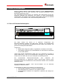
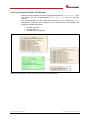
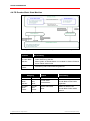
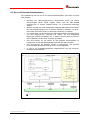
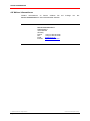
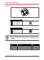
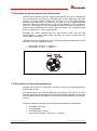

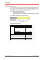
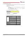
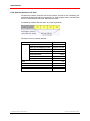
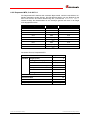
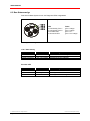
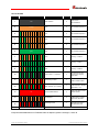
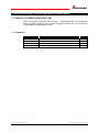

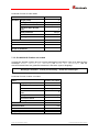

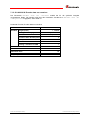
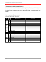

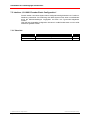


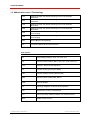
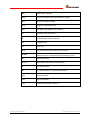
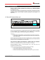
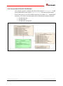

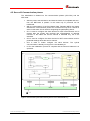

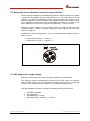
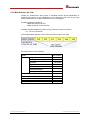
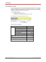
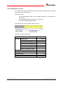

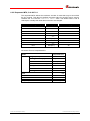

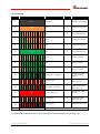
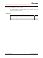
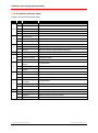
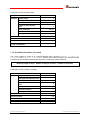
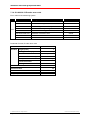
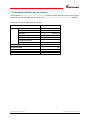
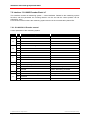
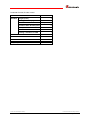
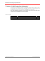
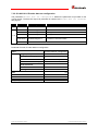
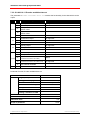
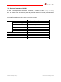


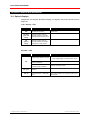
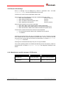
![English [2015v1]](http://vs1.manualzilla.com/store/data/005829431_1-1fdc30543d444fb0915a40c3aab945a8-150x150.png)