1
Cakewalk Z3TA+
User’s Guide
Benutzerhandbuch
Manuel de l’utilisateur
©
Information in this document is subject to change without notice and does not represent a commitment on the part of Twelve Tone Systems, Inc. The software described in this document is furnished
under a license agreement or nondisclosure agreement. The software may be used or copied only in
accordance of the terms of the agreement. It is against the law to copy this software on any medium
except as specifically allowed in the agreement. No part of this document may be reproduced or
transmitted in any form or by any means, electronic or mechanical, including photocopying and
recording, for any purpose without the express written permission of Twelve Tone Systems, Inc.
Copyright © 2005 Twelve Tone Systems, Inc. All rights reserved.
Program Copyright © 2005 Twelve Tone Systems, Inc. All rights reserved.
ACID is a trademark of Sonic Foundry, Inc.
Cakewalk is a registered trademark of Twelve Tone Systems, Inc. Z3TA+ and the Cakewalk logo
are trademarks of Twelve Tone Systems, Inc. Other company and product names are trademarks of
their respective owners.
Visit Cakewalk on the World Wide Web at www.cakewalk.com.
Les informations contenues dans ce document sont sujettes à modification sans préavis et ne
représentent pas un engagement de la part de Twelve Tone Systems, Inc. Le logiciel décrit dans ce
document est fourni sous accord de licence ou de confidentialité. Le logiciel ne peut être utilisé ou
copié que conformément aux termes de cet accord. Il est illégal de copier ce logiciel sur tout support
excepté comme autorisé spécifiquement aux termes de l'accord. Aucune partie de ce document ne
doit être reproduite ou transmise sous quelque forme ou de quelque façon que ce soit,
mécaniquement ou électroniquement, y compris par photocopie et enregistrement, à toute fin que ce
soit, sans l'autorisation écrite expresse de Twelve Tone Systems, Inc.
Copyright © 2005 Twelve Tone Systems, Inc. Tous droits réservés.
Copyright du programme © 2005 Twelve Tone Systems, Inc. Tous droits réservés.
Cakewalk est une marque déposée de Twelve Tone Systems, Inc. Z3TA+ et le logo Cakewalk sont
des marques de Twelve Tone Systems, Inc. Les autres noms de société et de produit sont les
marques de leurs propriétaires respectifs.
Visitez le site de Cakewalk sur internet : www.cakewalk.com.
Die Informationen in diesem Dokument unterliegen Änderungen ohne vorherige Ankündigung und
stellen keine Verpflichtung von Seiten von Twelve Tone Systems, Inc dar. Die in diesem Dokument
beschriebene Software wird im Rahmen einer Lizenz- oder Nichtveröffentlichungsvereinbarung
bereit gestellt. Die Software darf nur in Übereinstimmung mit den Vereinbarungsbedingungen
verwendet oder kopiert werden. Das Kopieren dieser Software auf ein anderes Medium als im
Rahmen der Vereinbarung ausdrücklich zugelassen ist verboten. Ohne ausdrückliche schriftliche
Genehmigung von Twelve Tone Systems, Inc. darf kein Teil dieses Dokuments in irgendeiner Form
oder auf irgendeine Weise, weder elektronisch noch mechanisch, einschließlich von Fotokopien
oder Auszeichnungen, zu irgendeinem Zweck reproduziert oder übertragen werden.
Copyright © 2005 Twelve Tone Systems, Inc. Alle Rechte vorbehalten.
Programm Copyright © 2005 Twelve Tone Systems, Inc. Alle Rechte vorbehalten.
Cakewalk ist eine eingetragene Marke von Twelve Tone Systems, Inc. Z3TA+ und das CakewalkLogo sind Marken von Twelve Tone Systems, Inc. Alle anderen Firmen- und Produktnamen sind
Marken ihrer jeweiligen Rechtsinhaber.
Besuchen Sie Cakewalk im World Wide Web unter www.cakewalk.com.
Table of Contents
Table des Matières
Inhaltsverseichnis
1 Table of Contents
Table des Matières
Inhaltsverseichnis iii
Interacting with Z3TA+: Graphical User Interface (GUI) 9
Main Pages and Sub-Pages 9
2 English 9
Top Panel 10
Preview Ribbon 10
Shaper, X-Y, and Analyzer Windows 10
The Controls 11
The Sliders 11
The Selectors 12
The Range 13
Master Section 14
Master Section Buttons 15
The Synthesizer 15
Oscillator Parameters 18
Oscillator Modes 18
Oscillator Modulation Modes 19
Oscillator Global 19
PWM 20
Shaper 20
Shaper Transformations 21
Filters 22
Filter Parameters 22
LFOs (Low Frequency Oscillators) 23
LFO Parameters 24
LFO Modes 24
Arpeggiator 25
Arpeggiator parameters 26
EGs (Envelope Generators) 26
Amplifier (A) and General-Purpose EG (1-6) Parameters 27
Pitch EG Parameters 28
The Matrix: Taking the Red Pill 28
Some history for young people 29
Matrix Overview 30
Term Definitions 30
Matrix Sources 31
Matrix Curves 31
Matrix Controls 32
Matrix Destinations 32
Velocity Curves 34
The Effects 34
Drive 35
Drive parameters 35
Drive Modes 35
Modulation 36
Modulation Parameters 36
Modulation Modes 37
Modulation Equalizer Modes 37
Compressor 38
Compressor Parameters 38
Delay 38
Delay Parameters 38
Delay Modes 39
Delay Equalizer Modes 39
Reverb 40
Reverb Parameters 40
Reverb Modes 40
Equalizer 40
Equalizer Parameters 41
Simulator 41
Limiter 41
Programs and Banks 41
Copy/Paste/Paste Special/Swap/Initialize Programs 42
Get Effects from Program File 42
Default Programs File 42
Saving and Loading Program and Bank files 43
Saving MIDI Bank files (.128) 43
Audio Input 43
MIDI Learn 44
Copy and Paste functions 45
Microtuning, Alternative tunings 45
Hermode Tuning 46
iv
Z3TA+ Waveshaping-Synthesizer 49
Die Bedienoberfläche des Z3TA+ 49
3 Deutsch 49
Hauptseiten und Subseiten 50
Kopfleiste 50
Das Preview Ribbon 51
Die Fenster Shaper, X-Y und Analyzer 51
Die Bedienelemente 52
Schieberegler 52
Auswahlfelder 53
Bereichsregler 54
Der Bereich Master 55
Die Schaltflächen im Bereich Master 56
Der Synthesizer 57
Waveshaping-Oszillatoren 57
Oszillatorparameter 60
Oszillatormodi 61
Modulationsmodi 62
Globale Oszillatoren-Einstellungen 62
PWM 64
Der Shaper 64
Shaper-Transformationen 65
Filter 66
Filterparameter 67
LFOs 67
LFO-Parameter 68
LFO-Modi 69
Arpeggiator 69
Arpeggiatorparameter 70
Hüllkurven 70
Parameter der Hüllkurven A und 1 bis 6 71
Parameter der Hüllkurve P 72
Nehmen Sie die rote Pille… die Matrix! 73
Ein paar historische Anmerkungen für jüngere User… 74
Übersicht zur Matrix 75
Begriffsdefinitionen 75
Modulationsquellen 76
Kurven 77
Controller 77
Modulationsziele 78
Anschlagsdynamikkurven 79
Die Effekte 80
Verzerrer 80
v
Verzerrerparameter 81
Verzerrermodi 81
Modulation 81
Modulationsparameter 82
Modulationsmodi 82
Modi des Modulationsequalizers 83
Kompressor 83
Kompressorparameter 84
Delay 84
Delayparameter 84
Delaymodi 85
Modi des Delayequalizers 85
Reverb 86
Reverb-Parameter 86
Reverb-Modi 86
Equalizer 86
Equalizerparameter 87
Simulator 87
Limiter 87
Programme und Bänke 87
Programme kopieren, tauschen und initialisieren 88
Effektschablonen verwenden 88
Auswahl der beim Start geladenen Datei 89
Programm- und Bankdateien speichern und laden 89
MIDI-Bankdateien speichern 89
Audioeingang 90
Die MIDI-Learn-Funktion 90
Kopierfunktionen 91
Microtuning und alternative Stimmungen 92
Hermode Tuning 93
Z3TA+ Waveshaping Synthesizer 95
Interaction avec le Z3TA+: interface graphique 95
Écran 95
4 Francais 95
Pages principales et sous-pages 96
Panneau supérieur 96
Ruban de pré-écoute 97
Fenêtres Shaper, X-Y et Analyzer 97
Les commandes 98
Les curseurs 98
Les sélecteurs 99
Le paramètre de plage (Range) 100
vi
Section Master 101
Boutons de la section Master 102
Le synthétiseur 102
Oscillateurs de mise en forme d’onde 102
Paramètres des oscillateurs 104
Modes d’oscillation 105
Modes de modulation des oscillateurs 106
Page globale des oscillateurs 106
PWM 107
Shaper (outil de mise en forme) 108
Paramètres de transformation du Shaper 108
Filtres 109
Paramètres des filtres 110
LFO (Low Frequency Oscillators) 110
Paramètres des LFO 111
Modes de LFO. 112
Arpégiateur 112
Paramètres de l’arpégiateur 113
Générateurs d’enveloppes (EG) 113
Paramètres de l’EG d’amplification (A) et des EG polyvalents (1-6) 114
Paramètres de l’EG du pitch 115
La matrice : choisissez la pilule rouge 116
Une peu d’histoire à l’attention des plus jeunes 116
Présentation générale de la matrice 118
Définitions 118
Sources de la matrice 118
Courbes de la matrice 119
Ontrôles de la matrice 120
Destinations de la matrice 120
Courbes de vélocité 122
Les effets 122
Excitation (drive) 123
Paramètres d’excitation 123
Modes d’excitation 124
Modulation 124
Paramètres de modulation 124
Modes de modulation 125
Modes d’équalisation par modulation 126
Compresseur 126
Paramètres de compression 126
Delai (delay) 126
Paramètres du délai 127
Modes de délai 127
Modes équaliseur de délai 127
vii
Reverb 128
Paramètres de la reverb 128
Types de reverb. 129
Equaliseur 129
Parametres d’équalisation 129
Simulateur (simulator) 129
Limiteur (limiter) 129
Programmes et banques 130
Copier les effets d’un programme 131
Programmes par défaut 131
Enregistrer et charger des programmes et des banques 131
Enregistrer des banques MIDI (.128) 132
Entrée Audio 132
Apprentissage MIDI (MIDI-learn) 132
Fonctions copier (copy) et coller (paste) 134
Microtuning et autres accords 134
Hermode Tuning 135
viii
English
INTERACTING WITH Z3TA+: GRAPHICAL USER
INTERFACE (GUI)
Z3TA+ was designed to fit on the screen even at low resolutions like 800x600,
which makes it very appropriate for live use on low-resolution notebooks and
laptops. However, you'll be more comfortable running it at 1024x768 or higher
resolutions. True color (24 or 32-bit color) is the best setting to clearly see all
Z3TA+ interface details.
By opening the deployable Shaper, X-Y and Analyzer windows, you can keep on the
screen only required functions, which are different during programming, sound
design, and live performance.
The Z3TA+ skin can be changed by replacing a few standard bitmap files, which
are installed in the Skin folder. This method lets you renew the look of Z3TA+
without complex installation procedures.
Main Pages and Sub-Pages
Here's a description of the Z3TA+ interface:
•
Two main pages: Synth and Effects
•
Numerous sub-pages for specific components
•
Deployable windows for Shaper, X-Y Pad, and Analyzer
When Z3TA+ starts, it displays the Synth page. Use the Effects button in the
Master section (lower right corner) to toggle between the Synth and Effects pages.
The Synth and Effects main pages contain several sub-pages for every component.
For example, to switch between the six oscillators (and the oscillators Global page),
use the Oscillator page buttons (1-6). When you change pages, the controls show
the settings for the corresponding oscillator. The same applies to filters, LFOs,
EGs, Modulation Matrix, and delays.
Top Panel
The top panel has the controls for program and bank selection.
Z3TA+ includes 768 program slots, grouped in six banks (A-F) of 128 programs
each. You can select a bank of programs by clicking (and/or dragging) in the Bank
Selector (A-F). (The bank also changes when Z3TA+ receives a MIDI Bank Change
message.) Right-clicking the letter for the selected bank displays a list of all
programs in the current bank. The current program appears in bold in this list.
You can navigate within the list by using the arrows or by clicking the first letter of
the desired program. For instance, pressing A in factory bank C will show “Angel
Pad” then “Antique Space Pad.”
The currently selected program name is displayed in the Program Selector. To
browse through the programs, just left-click (next) or right-click (previous) on the
name of the current program. To change the program name or enter a new one,
Shift-left-click on the name.
See “Programs and Banks” on page 41 for more information on using programs
and banks.
Preview Ribbon
Z3TA+ features the unique Cakewalk Preview Ribbon, which allows you to
preview programs by clicking and dragging on it. The Preview Ribbon, at the
bottom of the screen, plays different note velocities as you click higher or lower
within the ribbon.
The ribbon sends MIDI Note-On/Note-Off messages with velocity to the host when
Z3TA+ is used as VSTi/DXi, so those events can be recorded in real time if the host
supports that feature.
The number of notes being played (polyphony) is shown in the Voices indicator in
the Master section. The ribbon is very useful to set release times, performing a
glissando by dragging the mouse over it.
Shaper, X-Y, and Analyzer Windows
There are three components of Z3TA+ that run in separate windows: the Shaper,
the X-Y Pad, and the Analyzer. Each has its own dedicated activation button:
Shaper (Oscillators section), X-Y (Matrix section), and Analyzer (Master
section).
The X-Y Pad allows you to modulate any pair of parameters on Z3TA+ by using the
mouse.
Right-clicking on it causes random movement, useful for sample-and-hold-like
effects.
The position of the X-Y Pad is saved in the program, and all movements can be
recorded as automation in all hosts supporting direct parameters automation.
10
X-Y Pad X and Y movements can be MIDI-learned by Shift-clicking on the X-Y
Pad. For more information about MIDI Learn, see “MIDI Learn” on page 44.
Additionally, the X-Y Pad will respond to joystick movements if a joystick is
connected and configured in Windows Control Panel.
The Analyzer shows the frequency spectra of the sound being played. This is
especially handy when you're using the Waveshaper.
As those components are not used all the time, they can be hidden, saving screen
space. Also, they can easily be moved to secondary screens if you’re using multiple
monitors.
The Controls
All the controls in Z3TA+ were specially designed to provide maximum flexibility
and convenience while consuming a minimum of screen space. They fully support
mouse, mouse wheel, and keyboard commands to perform the functions described
below.
The Sliders
Sliders control most parameters with continuous values (for example, Level, Tune,
and Cutoff). The sliders on Z3TA+ are inertia-driven to allow smooth parameter
transitions no matter how far apart the values are. There are two kind of sliders:
unipolar (min to max), and bipolar (centered). The bipolar sliders are marked with
a bold horizontal line in the middle.
To move a slider, simply click and drag on it, or click directly on the new position.
After you click on a slider (with the left mouse button or the mouse wheel button),
it will retain focus, so you can move it by using the PC keyboard and/or the mouse
wheel. The focus is indicated by a vertical blue light in the selected slider.
The PC keyboard allows for several speeds of variation while adjusting sliders:
Left/Right arrows
Very small steps used for precise adjustments. 200 steps from min to
max.
Up/Down arrows
Small steps used for standard adjustments. 40 steps from min to max.
Page Up-Page Down
Big steps, quick change. 8 steps from min to max.
CONTROL key plus
any of the above
OR
Double-click
Set the default parameter value (centered for all bipolar sliders, the
“natural” value for all unipolar sliders).
When using the mouse, use the standard left button to move the slider, and use the
right button to MIDI-learn the slider. Holding down the CONTROL key while
11
clicking on a slider resets to its default position, which will be the “natural” point
for that parameter. You can do the same thing by double-clicking on it.
The mouse wheel can be used to move the slider that has the focus in small steps
(normal) or in big steps (by holding the SHIFT key) while moving the wheel. These
actions will move the slider that has focus, regardless of where the mouse is, so it's
important to select the slider first.
You can assign any MIDI controller to any slider by right-clicking on it. If the
parameter range is scaled (using min or max), the range of the scale will be shown
with an indicator on the slider. After you've made the assignment, the sliders will
move according to incoming MIDI messages. For more information about assigning
MIDI to a slider, see “MIDI Learn” on page 44.
The Selectors
The selectors allow you to choose settings for parameters (for example, Waveform
and Transpose) that have discrete values.
Use the standard left/right click to select the next/previous discrete value. When
the value reaches the maximum, it will wrap to the minimum, resulting in fewer
clicks to reach the desired value. Once you click on a selector (with the left mouse
button or the mouse wheel button), it retains focus, so you can use the PC
keyboard and the mouse wheel to change values as with the sliders. Text in the
selected control is in bold.
The PC keyboard allows for several speeds while adjusting text selectors:
Up/Down arrows
Next/Previous discrete value
Page Up/Page Down
10 steps increment or decrement in the current discrete value
As with the sliders, holding down the CONTROL key while clicking on the text
selector resets the selector to its default position, which will be the “natural” point
for that parameter (for example, transpose = 0). You can get the same effect by
using the left and right mouse buttons together.
You can use the mouse wheel to move the selector in small steps (±1 discrete value
increment). These actions will move the selector in focus, regardless of where the
mouse is, so it's important to select the slider first.
Parameters with many values (for example, Oscillator, LFO waveforms and Tempo
Sync) feature a different indicator (right arrow) on the right. Clicking on it
displays a menu that allows direct selection of the value.
Using a combination of the above techniques (browse and direct selection) will
provide the quickest workflow.
12
You can assign any MIDI controller to any selector by right-clicking on it. The
selectors will move according to incoming MIDI messages and scaling when
“learned.” For more information about this, see “MIDI Learn” on page 44.
The Range
The Range parameter in the matrix also uses a specially designed control that
allows you to set two parameters in the same control: Min and Max, by using left
and right click and drag operations. Range controls also keep the focus, and allow
for keyboard and mouse wheel adjustments in different sized steps:
Left/Right arrows
±1% of the control
Up/Down arrows
±5% of the control
Page Up/Down
±20% of the control
Wheel Up/Down
±5% of the control
Shift + Wheel Up/Down
±1% of the control
When you operate the Range controls in the Shaper, the mouse pointer disappears
and the selectivity of the operation is expanded to ensure smooth waveshaping
transitions.
On the Effects page, the Drive and Compressor sections use a similar Range
control, but their Min parameter is disabled.
You can assign any MIDI controller to any Range control by Shift-right-clicking on
it. The controls will move according to incoming MIDI messages and scaling when
“learned.” For more information about this, see “MIDI Learn” on page 44.
13
Master Section
The Master section provides a convenient view of the most common parameters
(Polyphony, Render mode, and Master Output Level) for the currently selected
program and the overall status of the synthesizer (played voices, level indicator).
This section is visible on both Synth and Effects pages.
Control
When you move a slider/range control (or when the mouse pointer is
over it), this label shows the name of the selected parameter.
Value
When you move a slider/range control (or when the mouse pointer is
over it), this label shows the value of the selected parameter.
Render Mode
Sets the output quality to Draft, Normal, or High.
Draft: Bandwidth is limited to one-fourth of the selected sample rate (for
example, 11KHz @44100). Little high-frequency content is generated.
Heavily filtered programs (for example, the Boom Bass factory preset)
don’t need the full oscillator bandwidth, as it would be removed in the
next synthesis stage (the filter). In these cases, using Draft mode allows
for significant CPU savings.
Normal: Standard mode for most programs. Standard-order interpolation
and control rate settings are used, so full bandwidth is expected.
High: Higher-order interpolation is activated, and control rate is
increased (perceivable when modulating individual oscillator levels or
individual EQ bands with high-transition sources, such as an LFO with
square wave). Preferred mode for final renderings.
Polyphony
Sets the program’s maximum polyphony to 1, 2, 3, 4, 5, 6, 8, 12, 16, 24,
32, or 64 voices. The intelligent voice allocation scheme will decide
which notes to turn off based on several parameters (envelope generator
release stages, sustain switch, psycho-acoustic priorities, etc.) to keep
the voice number within the selected limit.
Even with a fairly low voice number setting (6-8), it’s possible to play
complex harmonies real-time without artifacts.
When Polyphony is set to 1, Z3TA+ activates the full-legato monophonic
operation. When in this mode, the envelope generators don’t restart on
overlapping note transitions.
14
Master Volume
Output level for the selected program.
Output VU meter
Left and Right output volume is shown in the main VU meter as Volume
Units.
Master Section Buttons
In the MASTER section, there are dedicated buttons to handle program and bank
files and to select other miscellaneous functions such as main MIDI velocity curve
settings.
EFFECTS
ANALYZER
Switches the main view to the Effects page or back to the Synth
page.
When you right-click this button, all effects (with the exception of the
polyphonic Drive and the master Limiter) are bypassed, allowing you
to hear the current program in “dry” status. A blinking red LED
indicates this status.
Opens and closes the deployable Analyzer window.
When turned off, it uses no CPU cycles.
PROGRAM
Contains options to copy/swap/paste/initialize and load/save
individual program files.
See “Programs and Banks” on page 41.
BANK
Contains options to save bank files, and use the default file.
See “Programs and Banks” on page 41.
LIMITER
Turns the main output Limiter on and off.
OPTIONS
Allows you to choose several options, including Main Velocity
Curves, Audio Inputs, Alternative tunings, and Hermode Tuning.
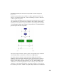
The Synthesizer
WAVESHAPING OSCILLATORS
A Waveshaping Oscillator is the Z3TA+ component responsible for sound
generation.
There are six waveshaping oscillators, each with 60 waveforms from, including six
user-created waveforms. USER1, USER2, and USER3 waveforms are shipped with
Z3TA+ as examples.
You can use the Shaper to shape any oscillator's waveform independently to create
very complex waveform stacks, combining different shaper settings for different
oscillators.
All shaping content for the six oscillators is stored as part of the program.
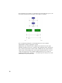
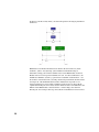
There are two output busses for mixing oscillators, which are routed to Filter1 and
Filter2 respectively. Later, at the filter stage, the filters' output is panned in the
stereo field. This design lets you create mono or stereo programs and position
individual oscillators precisely in the stereo field. So you have two ways to control
15
the pan position of an oscillator: (1) determine how much of its signal goes to each
bus, and (2) determine the pan position of the output of each filter.C
You can adjust the pitch, phase, and startup behavior of every oscillator
individually by using the appropriate controls.
Additionally, each oscillator features a Multi mode in which it becomes eight
individual oscillators (four stereo oscillators) with adjustable detune, allowing for
huge, animated pads and hoover-like sounds. In Multi mode the eight oscillators
require about as much CPU power as two normal oscillators. However, a word of
caution about CPU usage is needed here: Z3TA+ will allow you to set the six
oscillators in Multi mode, resulting in… 48 oscillators per note! Keep an eye in the
CPU indicator on your favorite host.
16
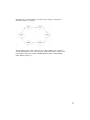
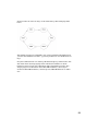
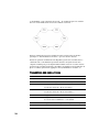
All oscillators can inter-modulate each other using a unique “circular intermodulation scheme,” as follows:
Any modulation option can be chosen in any oscillator. This way, the output of
combined modulations can become extremely complex. For instance, OSC1 could
ring-modulate OSC2, this output could FM-modulate OSC3, to PM-modulate
OSC4, SYNC to OSC5, etc.
17
Oscillator Parameters
Waveform
Oscillator waveform
Transpose
-12 to +12 semitones in one-semitone steps
Octave
-5 to +5 in one-octave steps
Mode
Oscillator mode.
Group
Modulation mode.
See “Oscillator Modulation Modes” on page 19.
Fine
-100 to +100 cents fine-tune adjustment
Phase
0 to 360 degrees start phase adjustment.
This slider becomes “Multi Detune” when Multi mode is used.
Bus
Mixing bus assignment, from full Bus1 to full Bus2
Level
Output level of the oscillator
Oscillator Modes
NSYNC
Normal polarity, key sync.
This is the standard mode. The phase of the oscillator will start on the point set
by the Phase control on every Note-On event.
ISYNC
Inverted polarity, key sync.
Same as NSYNC, but with the output polarity of the oscillator inverted.
NFREE
Normal polarity, free running.
The oscillator phase doesn’t restart on Note-On events. Preferred mode for
monophonic sounds.
IFREE
Inverted polarity, free running.
Same as NFREE, but with the output polarity of the oscillator inverted.
SMULTI
Synchronized Multi mode.
This mode turns the oscillator into eight simultaneous oscillators.The
oscillators' detune amount is controlled with the Phase slider. Four oscillators
output are sent to Bus1, and four to Bus2, spreading the output in the stereo
field (if the filters are hard-panned to L and R).
In this mode, the phase is restarted on every Note-On event.
FMULTI
Free running, Multi mode.
Same as SMULTI, but oscillators' phase isn’t restarted on Note-On events.
SFIX
Fixed frequency.
In this mode the oscillator pitch won’t follow the keyboard, generating a fixed
tone instead. Phase is restarted on Note-On events.
FFIX
Fixed Frequency.
Same as before, but oscillator phase won’t restart on Note-On events.
18
OSCILLATOR MODULATION MODES
ADD
Normal oscillator mode.
The output of the oscillator is sent directly to mixing busses according to the
Bus setting, and no modulation is performed.
RING
Ring modulation.
The output of this oscillator is used to ring-modulate the next one in the
circular chain.
SYNC
Hard sync modulation.
The next oscillator in the chain will be “slave” of this oscillator, so it will restart
its phase every time this oscillator restarts.
PM
Phase modulation.
Next oscillator phase will be modulated with the output of this oscillator.
FM
Analog frequency modulation.
The frequency of the next oscillator in the chain will be modulated with the
output of this oscillator.
OSCILLATOR GLOBAL
This sub-page in the Oscillators section includes settings that will affect the
output of all oscillators together, as follows:
Main Transpose
-12 to +12 semitones, in 1-semitone steps.
Transpose of the whole program.
All oscillators will be affected by this setting.
Bend Mode
Bend Up
Pitch Bend mode:
•
Low: When playing a chord, only the lowest-pitched note is bent.
•
High: When playing a chord, only the highest-pitched note is
bent.
•
Hold: Only pressed keys (not including the ones in release stage
or those held with sustain switch) are bent.
•
Normal: Standard pitch bend mode.
-12 to +12 semitones, in 1-semitone steps.
Interval to bend when the Bend wheel is turned fully up.
Bend Down
-12 to +12 semitones, in 1-semitone steps.
Interval to bend when the bend wheel is turned fully down.
19
Porta Mode
Portamento Mode.
Norm, Fix: Normal mode, with a fixed time (set by the P. Time
parameter) for the new note to reach its pitch. In legato mode (See
“Master Section” on page 14) portamento is in effect even when the
first note has been released.
Norm, Var: Normal mode, with portamento time depending also on the
interval between the notes.
Fing, Fix: Fingered mode with fixed time. In legato mode the first note
must be held in order for the portamento glide to take place.
Fing, Var: Fingered mode, with portamento time depending also on
the interval between the notes.
Off: No portamento
P. Time
Portamento time, from 0 to 10 seconds.
Burst
Filtered DC-Burst level.
This will create a “pop” on Note-On, mostly used to recreate old analog
drum machine sounds, or to add some punch to a program.
Random
Random detuning level.
This feature is commonly used to emulate the tuning instabilities in
early analog synthesizers.
The random detune affects every oscillator individually.
Main Tune
Main tuning of the whole program.
All oscillators are affected by this setting.
PWM
All oscillators on Z3TA+ support pulse width modulation in any waveform, and by
using any modulation source, including fixed control of modulation amount, LFOs,
EGs, keyboard scaling, and voice number. For more information about modulation
sources, see “The Matrix: Taking the Red Pill” on page 28.
SHAPER
As described in the introduction, Z3TA+ features a unique Waveform Shaper,
which creates fully band-limited waveforms on the fly using several complex
transformations. With the aid of its waveform display, all the changes are seen and
heard in real time.
To use the Shaper, select the desired waveform in any oscillator and invoke it by
clicking on the Shaper button in the Oscillators section.
20
Shaper Transformations
DC Adjust
Adjusts the waveform DC offset, to compensate for deviations produced
by other transformations.
Click and drag vertically on the waveform display to adjust.
Symmetry
Adjusts the waveform symmetry by stretching the two halves of the wave.
In a square wave, for instance, it adjusts the pulse width (similar to
adjusting the pulse width using the Matrix).
Click and drag horizontally on the waveform display to adjust.
Warp
Wraps around the waveform when the amplitude goes over the selected
threshold point.
Twist
Wraps around and inverts the polarity of the waveform when its amplitude
goes over the selected threshold point.
Multipoint
Makes the waveform zero at three points.
The control adjusts the width of the zeroed section.
Window
Processes the waveform with a triangular window envelope. This
transformation results in the extremes of the waveform being more
attenuated than the middle.
Drive
Boosts and clips the output as a hard clipping stage.
Wave
Partially morphs the waveform into a sine. Mostly used to reinforce the
fundamental in a weak waveform.
Offset
Wraps around and inverts the polarity of the wrapping. Similar to Twist,
but with opposite polarity.
Shrink
Shrinks the whole cycle, filling the rest with zeros.
SelfSync
Stretches the whole cycle, filling the rest with the same waveform after
stretching. Produces a sound similar to “hard-sync” inter-modulation
mode.
Bit Reduction
Bit reduction.
Adjusts the bit depth in a 1-32 bit range.
HPF
Highpass Filtering
LPF
Lowpass Filtering
You can reset all transformations in the Shaper at once. To perform this operation,
right-click on the waveform display in the Shaper window and select the Reset all
shapers option.
All Range controls in the Shaper can be assigned to MIDI controls with adjustable
range. For more information about this, see “MIDI Learn” on page 44.
The transformations in any oscillator can be copied and pasted to other oscillators.
For more information on this, see “Copy and Paste functions” on page 45.
21
Filters
Z3TA+ has two stereo filters (four filters total), which process the oscillatorss
mixing busses.
The filters can be organized in Single mode or in Dual mode. When in Single mode,
both filters are mono and they are completely separate units working in parallel.
When in Dual mode, the filters are stereo and the output of Filter1 is routed to
Filter2. In this way, many filter combinations can be achieved.
Both filters are identical, and have different working modes, including the
standard 12dB and 24dB per octave lowpass, bandpass, highpass, and bandrejection, plus a 36dB lowpass and a formant filter, used to emulate vowel sounds.
The 24dB/Oct and 36dB/Oct LPF filters in Z3TA+ are composed of two sections
(three for the 36 dB/Oct), to support a Separation parameter that allows for a
cutoff separation between the component filters. This parameter can be modulated
using any modulation source using the Matrix. For more information, see “The
Matrix: Taking the Red Pill” on page 28.
The Link button lets you adjust controls in both filters at same time. In this way,
when Link is active, adjusting the level of Filter1 also adjusts the level of Filter2.
NOTE: When Link is active, adjusting the Pan control in Filter1 to left will result
in Filter2 pan being adjusted to right. This allows spreading the filters in stereo by
using only one control.
Filter Parameters
Filter Type
Selects the filter type.
Filter Limiter
Changes the filter limiter response time between Off, Slow, and Fast.
Reso boost
Resonance booster.
Changes the resonance scaling factor to accommodate higher resonance
modes.
22
Cutoff
The filter cutoff point.
Resonance
The filter resonance.
Pan
Defines the stereo position of the filter output, from full L to full R.
Level
Filter output level.
LFOs (Low Frequency Oscillators)
The LFO section in Z3TA+ is one of the most powerful ever designed. There are six
dual LFOs-- four global (affecting all voices at once) and two local (affecting
individual voices).
For each LFO you can select among 60 waveforms, including ten user-designed
waveforms, and three different random and sample and hold options. USER1
waveform is shipped with Z3TA+ as an example.
A single LFO actually consists of two independent LFOs, which can be combined in
several ways, including time morphing and many mathematical functions.
All LFOs can be synchronized to host tempo, and they will track the host bar
position to keep tracking even on the event of dynamic tempo changes in the host.
Global LFO (1-4)
All voices in a program are affected by the same LFO value.
Local LFO (5-6)
Each voice in a program has its own LFO.
23
LFO Parameters
Wave 1
The main waveform for the LFO.
Waveforms 1 and 2 are combined according to the “LFO Mode” setting.
Tempo Sync
The beat division when synchronizing to host tempo.
A indication of “1” means one beat, so if the host tempo is set to 120 bpm
the LFO will produce 120 cycles in this setting.
Phase
The starting phase for the LFO on Note-On, in 45-degree steps.
When you select “Free,” the LFO won’t restart its phase on Note-On
events.
Mode
LFO Mode.
See “LFO Modes” on page 24.
Wave 2
The secondary waveform for the LFO.
Waveforms 1 and 2 are combined according to the LFO Mode setting.
Offset
-1 to +1.
Value offset for the LFO output.
Delay
0 to 10s.
The delay before the LFO starts its operation after a Note-On event is
received.
Fade
0 to 10s.
The fade-in time for the LFO. The LFO output will gradually rise from
zero to reach its maximum after Fade time.
Time
0 to 10s.
The time for the Morph operation. This slider has some other uses,
according to the LFO mode. Check the “LFO Modes” table for more
information.
Speed
0.01Hz to 20Hz.
The LFO speed.
LFO Modes
24
MORPH
The output of the LFO will morph between Waveform1 and Waveform2
in the time set by Time slider.
ADD
The output of the LFO will be the mix of Waveform1 and Waveform2.
The mix balance is controlled with the Time slider. (The output won’t
change over time.)
IADD
Same as ADD, but Waveform1 is inverted.
SUB
Same as ADD, but Waveform2 is inverted.
ISUB
Same as ADD, but both Waveforms 1 and 2 are inverted.
MUL
Output of LFO is the sample-per-sample product of Waveform1 and
Waveform2
MIN
Output of the LFO is the minimum value between Waveform1 and 2:
LFO = min (wave1, wave2).
MAX
Output of the LFO is the maximum value between Waveform1 and 2:
LFO = max (wave1, wave2)
HALF1
The output of the LFO is the first half-cycle of Waveform1 and second
half-cycle of Waveform2.
HALF2
The output of the LFO is the first half-cycle of Waveform2, and second
half-cycle of Waveform1.
ONE-SHOT
The LFO will output only one cycle, then it will stop.
Combining Waveforms 1 and 2 with all the LFO modes, you can get some
extremely complex effects. Additionally, the LFO speed can be modulated with any
modulation source.
Arpeggiator
Z3TA+ has a built-in arpeggiator, located on the last sub-page of the LFO section.
The arpeggiator features two operation modes: a standard algorithmic mode, used
to recreate standard up/down/random patterns, and a MIDI mode, in which it uses
one of the 100 pre-programmed patterns to process played notes.
The arpeggiator features sync to host tempo, and to bar position so it will keep
track if the host tempo changes dynamically.
Arpeggiator settings are stored in the program.
25
Arpeggiator parameters
Pattern
Arpeggiator pattern.
Algorithmic mode: Up, Down, Up/Down 1 (last note not repeated), Up/
Down 2 (last note repeated), and Random.
MIDI mode: ARP000 to ARP099. The Arpeggiator plays the selected
pattern, created from a standard MIDI file.
Sync
The beat division when synchronizing to host tempo.
Octaves
1 to 6. The arpeggiator extension.
This control has no effect in MIDI mode.
Mode
Sets phase restart mode.
When Mode is set to Free, phase won’t restart on Note-On events.
Sort
Determines whether the notes are sorted before producing the arpeggio
or not.
This setting has no effect in MIDI mode.
Velo
The Note-On velocity of the Arpeggiator.
The effect of velocity will depend on the program velocity assignments.
Duration
Length of the notes in the arpeggio.
This control has no effect in MIDI mode.
Speed
Arpeggiator speed.
EGs (Envelope Generators)
There are eight envelope generators in Z3TA+:
•
One bipolar envelope generator (P, usually assigned to pitch)
•
One main amplifier envelope generator (A)
•
Six general-purpose unipolar envelope generators
All EGs excepting the Pitch EG are 5-stage generators, with selectable curve for
each stage.
There is a Delay control in every EG, which allows you to set the delay between
Note-On event and the start of the EG.
Also, the output level of any EG can be adjusted with the Amount control. The
effect can be reversed, as Amount can be set to both positive and negative values.
26
Amplifier (A) and General-Purpose EG (1-6)
Parameters
Delay
0 to 10s.
The time from Note-On event till start of the EG.
Attack Time
0 to 10s.
After the delay stage, the EG starts rising from EG = 0 to EG = 1. It reaches
1 in the time set by this control, and following the curve set by Attack
Shape.
Attack Shape
Attack stage output will follow the curve selected by this control (linear,
exponential or power).
Slope Level
0 to 1.
After the attack stage, the EG reached EG = 1. Then it enters the slope
stage, which leads to EG = Slope Level, set by this control.
Slope Time
0 to 10s.
This control adjusts the time it takes the EG to perform the slope stage
(moving from EG = 1 to EG = Slope Level, following the curve set by Slope
Shape).
Slope Shape
The output variation during slope stage will follow the curve selected by
this control (linear, exponential, or power).
Decay Time
0 to 20s.
After the slope stage, the output will move from Slope Level to Sustain
Level, performing the decay stage, in the time set by this control.
Decay Shape
The output variation during decay stage will follow the curve selected by
this control (linear, exponential, or power).
Sustain Level
0 to 1 (0 to 100%).
After the decay stage, the output of the EG will remain at this value till a
Note-Off event is received for this note.
Release Time
0 to 10s.
When the Note-Off event is received for this note, the EG output will return
to zero. This control sets the time it takes to reach zero value.
Release Shape
The output variation during release stage will follow the curve selected by
this control (linear, exponential or power).
Amount
-1 to +1 (-100% to +100%, with zero at center).
The output level of the EG, in normal or reverse operation.
When this control is set to zero (default value, obtained by double-clicking
the control) all CPU usage for the EG is recovered.
27
Pitch EG Parameters
Delay
0 to 10s.
The time from Note-On event till the start of the EG.
Start Level
-1 to 1.
The initial value for the EG after the delay stage.
Attack Time
0 to 10s.
After delay stage, the EG will start the attack stage, where it will go
from EG = Start Level to EG = Attack Level. This control adjusts the
time to perform the attack stage.
Attack Level
-1 to +1.
The level the EG reaches after the attack stage.
Decay Time
0 to 10s.
After the attack stage, the EG will enter the decay stage, after which it
will reach EG = zero, and will remain in this status while the note is on.
This control adjusts the time to perform the decay stage.
Release Time
0 to 10s.
After note is released, the EG will enter the release stage, after which it
will reach EG = Release Level.
This control sets the time for the release stage.
Release Level
-1 to 1.
The final level for the EG after a Note-Off event is received for this
note.
Amount
-1 to 1.
The output level of the EG, in normal or reverse operation.
When this control is set to zero (default value, obtained by doubleclicking the control) all CPU usage for the EG is recovered.
As mentioned above, you can assign any slider or curve selector to any MIDI
controller by right-clicking on them (Shift-right-click for curve selectors). If the
parameter range is scaled (using min or max), the range of the scale will be shown
with a indicator in the slider background. For more information about assigning
MIDI to a slider, see “MIDI Learn” on page 44.
THE MATRIX: TAKING
THE
RED PILL
Most synthesizers have some modulation sources hardwired in some way to a
synthesizer component. While this is a very simple and effective approach, most
advanced sound programmers might find it limiting, as it doesn’t allow more
complex control connections as, in the above example, controlling the amount of
28
keyboard scaling being applied to the filter with an envelope generator triggered
on Note-On.
Z3TA+ features a very powerful Modulation Matrix that lets you link any
modulation source to almost any synthesizer and effects parameter, and it allows
you to assign a modulation range, curve, and control.LE
Some history for young people
Users of any synthesizer with a modulation matrix (for example, the outstanding
Oberheim Matrix 12), would remember the common modulation routing
procedure:
SOURCE -> RANGE -> DESTINATION
This is very powerful indeed, and was totally adequate for most synthesizers at
that time, where few MIDI controllers with ribbons, knobs, and sliders were
manufactured.
It allowed things like:
LFO1 -> 5% -> OSC1 PITCH
Nice and simple vibrato effect. Again, that was a very powerful method, but not
really enough to allow for expressive playing: what if we wanted to control the
vibrato amount using the modulation wheel?
That’s the point when the “control” concept appears. Many synthesizers had
different ways to assign a control in the mod matrix, but the overall scheme would
be represented as:
SOURCE -> RANGE -> CONTROL -> DESTINATION
Applied to our previous example:
LFO1 -> 5% -> MODWHEEL -> OSC1 PITCH
Now we can control the vibrato effect on Osc1 with the modulation wheel, from 0 to
5%. That’s exactly what doctor said.
So, what about having a small fixed vibrato in our lovely oboe patch, which would
turn stronger with the modulation wheel? That would be really powerful, but it
requires splitting the Range in two parts, Min and Max, to select the values of the
modulation when modulation wheel is at minimum, and maximum. Something
like:
SOURCE -> MIN -> MAX -> CONTROL -> DESTINATION
Translated to our example:
LFO1 -> 1% -> 5% -> MODWHEEL -> OSC1 PITCH
29
Now we have a fixed vibrato (1% of LFO1 applied to OSC1 Pitch), which turns into
5% when moving the modulation wheel to maximum. Can’t be better than this, can
it?
Well, what if I’d like a slower variation in the modulation wheel? Something like a
softer effect at the beginning, while getting strong at the end? It would need a
“variation curve,” something slower than standard:
SOURCE -> MIN -> MAX -> CURVE -> CONTROL -> DESTINATION
Or
LFO1 -> 1% -> 5% -> SLOW -> MODWHEEL -> DESTINATION
That’s really complete now. Just one row in the modulation matrix and I have all
vibrato on OSC1 complete. That’s exactly how the Z3TA+ Modulation Matrix
works. Let’s see another example:
“I’d like Filter1 cutoff controlled up to 30% by an LFO output passed through an
EG.”
Eh? What for? Err… OK.
LFO1 -> 0% -> 30% -> ULINEAR+ -> EG1 -> FILTER1 CUTOFF
That’s it. The Matrix in Z3TA+ allows for very complex modulation effects, as you
can check by “reverse-engineering” the factory presets. It's possible to create
animated, moving patches by combining several sources and destinations.
Matrix Overview
The Modulation Matrix has 16 rows, with Source, Range, Curve, Control, and
Destination controls. Despite this complexity, it can still be used as a simple
source/range/destination matrix for more elemental purposes.
Every external control and internal generator can used as source and control, and
most synthesizer and effects parameters are represented as Modulation Matrix
destinations. Following is a comprehensive list.
Term Definitions
Unipolar: A source is unipolar when the range of its output values is 0 to 1.
Bipolar: A source is bipolar when its range is in –1 to 1.
30
Matrix Sources
Off
0
LFO1-6
Bipolar
Output of LFOs 1-6.
Note that LFOs 1-4 are global, while LFOs 5 and 6 are
local (per-voice).
Pitch EG
Bipolar
Bipolar. Pitch Envelope Generator output.
EG1-6
Unipolar
Unipolar, positive or negative.
General-purpose EG 1-6 output.
Amp EG
Unipolar
Amplifier EG output.
Can have positive and negative values.
OSC1-6
Bipolar
Output of Oscillators 1-6.
The Oscillator Level control doesn’t affect the
amplitude of this source.
U-Random
Unipolar
Random value generated on Note-On
B-Random
Bipolar
Random value generated on Note-On
Fun1-4
Bipolar
Value of Function1 to Function4.
Can have positive and negative values.
X-Y Pad X, Y
Unipolar
X-Y Pad X and Y values
Unote#
Unipolar
Key note number (generally used for keyboard
tracking)
Bnote#
Bipolar
Key note number (generally used for keyboard
tracking)
Velocity
Unipolar
Note-On velocity
Rvelocity
Unipolar
Note-Off release velocity
Polyphony
Unipolar
Number of voices being played
On
1
Matrix Curves
Off
No curve processing
BLINEAR+
Bipolar processing (converts a bipolar source to unipolar)
BLINEAR-
Bipolar processing, reversed
ULINEAR+
Unipolar processing
ULINEAR-
Unipolar processing, reversed
SLOW+
Slow variation.
The source will be applied slower when control values are small.
31
SLOW-
Slow variation, reversed
FAST+
Fast variation.
The source will be applied faster when control values are small.
FAST-
Fast variation reversed
PITCH 4 Oct
Curve to be applied to any Pitch destination, ±4 octaves range
PITCH 1 Oct
Similar to previous, ±1 octave range
PITCH 1 Tone
Similar to previous, ±1 whole tone range
PITCH 1 Semitone
Similar to previous, ±1 semitone range
Matrix Controls
Off
No control
Velocity
Note-On velocity
Rel Velocity
Note-Off velocity
Ubend
Unipolar pitch bend
Bbend
Bipolar pitch bend
Polyaft
Polyphonic aftertouch
Chanaft
Channel (monophonic) aftertouch
Modwheel
Modulation wheel
Breath
Breath controller
Pitch Eg
Pitch envelope generator
EG1-6
General-purpose envelope generators 1-6
Amp Eg
Amplifier envelope generator
X-Y Pad X, Y
X-Y Pad X and Y
Audio Input
Audio input envelope followers for L (follow L), R (follow R), both
(follow LR)
Unote#
Unipolar note number
Bnote#
Bipolar note number
MIDI CC #3-#119
MIDI Continuous Controllers 3 to 119
Matrix Destinations
32
Off
No destination
Pitch Osc1-Osc6
Pitch of Oscillators 1 to 6
Pitch All Osc
Main program pitch (all oscillators)
PWM Osc1-Osc6
Pulse width of Oscillators 1 to 6
PWM All Osc
Pulse width of all oscillators
Cutoff Fil1, Fil2
Cutoff frequency of Filter 1, Filter 2
Cutoff All Filters
Cutoff frequency of both filters
Reso Fil1, Fil2
Resonance of Filter 1, Filter 2
Reso All Filters
Resonance of both filters.
Separation Fil1, Fil2
Separation of Filter 1, Filter 2
Separation All Filters
Separation of both filters.
Level Osc1-Osc6
Level of individual oscillators 1 to 6. When modulating this
parameter with fast-transient sources (for example, square wave
LFO), High Render mode is required for optimal parameter
smoothing.
Level All Osc
Amplitude level of all oscillators
Level Filter 1, Filter 2
Output level of Filter1, Filter2
Level all filters
Output level of both filters
Main volume
Main output volume. Note that this is a global parameter, and could
have unpredictable results when using a local source (for example,
EG) to modulate it on polyphonic operation.
F1f2 Osc1-6
Bus routing for oscillators 1-6
F1f2 All Osc
Bus routing for all oscillators
Pan Filter 1, Filter 2
Stereo panoramic position of Filter 1, Filter 2 output
Main Pan
Pre-effect stereo panoramic position
Speed LFO1-LFO6
Speed of LFO1 to LFO6
Fun1-Fun4
Functions 1 to 4. These work as virtual destinations to allow for
intermediate calculations, and they can be used as source in a
lower row in the matrix.
Chorus Level
Level of Modulation Unit
Chorus Depth
Depth of Modulation Unit
Delay1-Delay3 Level
Output level of Delay1 to Delay3 units
Delay1-Delay3 Lo
Low equalization of Delay 1 to Delay 3 units
Delay1-Delay3 Mid
Mid equalization of Delay 1 to Delay 3 units
Delay1-Delay3 Hi
High equalization of Delay 1 to Delay 3 units
Reverb Wet
Reverb wet/dry mix
Eq1-Eq7
Bands 1 to 7 of the stereo graphic equalizer
Decimator
Decimator amount
33
Velocity Curves
Z3TA+ features the ability to adjust the sensitivity curve for velocity to adapt it to
your style of playing, keyboard controller or sequencing style.
To change the velocity curve, select Velocity Curve under the Options menu and
choose the appropriate setting.
Linear
Standard velocity curve, no change.
Fast 1
Velocities will be processed as higher than normal, saturating at
maximum value when reached.
Fast 2
Velocities will be processed as higher as normal, saturating at
maximum value when reached. A fixed velocity offset will be added in
this mode. Very suitable for heavily compressed mixes.
Slow 1
Velocities will be processed as lower than normal.
Slow 2
Velocities will be processed as lower than normal with two different
curves for low and high velocities.
Expand 1
Low velocities will be even lower; high velocities will be even higher,
slight variation.
Expand 2
Low velocities will be even lower; high velocities will be even higher,
very noticeable variation.
Compress 1
Velocity range will be compressed to 30-127.
Compress 2
Velocity range will be compressed to 50-127, resulting in very small
dynamic range.
Hi Dynamic
Exponential curve, very big dynamic range
Lo Dynamic
Exponential curve, small dynamic range
The Effects
Z3TA+ has a complete effects processing section featuring several effects,
including drive (distortion, saturation, overdrive), chorus, flanger, phaser,
compressor, three fully independent delay lines, reverb, 7-band graphic EQ,
simulator, decimator, and limiter. All effects are grouped on the Effects page, so all
effects settings can be easily changed with minimum navigation.
All effects feature full stereo processing (which means every stage is actually two
stages, one for left and another for right channel), and can be turned off if external
processing is preferred, saving CPU usage.
Also, most effects parameters can be MIDI-learned, and some of them can be realtime modulated as destinations in the Modulation Matrix.
34
Drive
The polyphonic drive stage in Z3TA+ acts on the filters, creating non-linearities
ranging from subtle to aggressive. The special Heavy Metal mode adds a
monophonic distortion stage to the filters output, mostly used to create the classic
“power fifths” guitar effect.
Drive parameters
Mode
The drive mode.
See “Drive Modes” on page 35.
Destination
Drive effect can be applied to Filter1, Filter 2, or both.
This control sets where the drive effect will be applied.
Tone
Post-filtering stage.
This control adjusts the brightness of the distortion effect.
Deci
Sets the decimator amount.
The Decimator is a sample-rate reduction stage. It creates the “buzzy”
and “noisy” sound characteristic of early samplers and old computers.
Gain
Sets the drive stage gain.
Level
Sets the output level of the drive stage.
Drive Modes
Off
No drive effect.
Soft Drive
A very common drive sound, very suitable for leads and monophonic
sounds. The resulting distortion is very controllable for real-time
playing.
Hard Drive
A more aggressive, acid-oriented distortion.
Valve Amp
A very subtle distortion (except in extreme settings) modeled after a
valve (vacuum-tube-based) amplifier.
Smart Shaper
A level-controlled shaper.
This changes the drive characteristics depending on the incoming
signal amplitude. Very suitable for sounds with piano-like attack.
Heavy Metal
When this mode is engaged, a monophonic distortion unit will be
introduced after the output mix.
This allows for more “broken” sounds in polyphonic operations (ideal
for power-fifth intervals).
35
Modulation
The Modulation stage in Z3TA+ is capable of many different effects, including
several variants of chorus, flanger, and phaser.
It also features a built-in stereo equalizer, which controls the effect color.
Modulation Parameters
Mode
Modulation effect mode.
See “Modulation Modes” on page 37.
Tempo Sync
The beat division when synchronizing to host tempo.
Eq Mode
The equalizer mode.
See “Modulation Equalizer Modes” on page 37.
Waveform
The waveform for the modulation effect: SINE, SINE^3, TRIANGLE.
Depth
Adjusts the modulation depth.
Speed
The speed for the effect, from 0.01Hz to 10Hz.
Delay
The delay time for chorus and flanger effect.
This control also regulates the frequency range of phaser effects.
36
Feedback
Sets the amount of feedback.
Lo
Low equalization of the wet signal.
Hi
High equalization of the wet signal.
Level
The mix level for chorus and flanger, the output level for phaser effects.
Modulation Modes
Off
No effect.
Mono Chorus
A standard mono chorus effect.
The input signal is processed by adding both input channels. This effect
works best when processing sounds with heavy low-frequency contents (for
example, basses).
Stereo Chorus
This chorus effect processes both input channels with separate lines,
allowing for full stereo separation.
6-voice Chorus
Similar to Stereo Chorus effect, but three chorus lines process each
channel, resulting in a very wide and fat chorusing effect.
Mono Flanger
A standard mono flanger effect.
The input signal is processed by adding both input channels. This effect
works best when you want to add some flanging to sounds (for example,
basses) with heavy low-frequency content.
Stereo Flanger
This flanger effect will process both input channels with separate lines,
allowing for full stereo separation.
Mono Phaser
A standard mono phaser effect.
The input signal is processed by adding both input channels.
Stereo Phaser
Stereo phaser effect, which processes both input channels with separate
lines, allowing for full stereo separation.
Quad Phaser
Quadrature Phaser effect.
Similar to Stereo Phaser, but the modulation of both channels has reversed
polarity.
Chorus/Phaser
Combination of Stereo Chorus and Stereo Phaser.
Modulation Equalizer Modes
Off
No equalization (bypass)
Lo-
Lo = 250Hz, Hi = 500Hz
Lo+
Lo = 250Hz, Hi = 1000Hz
Mid-
Lo = 500Hz, Hi = 1500Hz
Mid+
Lo = 500Hz, Hi = 2500Hz
Hi-
Lo = 1000Hz, Hi = 4000Hz
Hi+
Lo = 500Hz, Hi = 8000Hz
37
Compressor
The stereo compressor in Z3TA+ is designed specially to add punch to the sound
more than for mastering songs. It is capable of very aggressive dynamic
manipulation, and its three speed settings allow for quick and precise attack/
release adjustments.
Compressor Parameters
Mode
Sets the compressor speed to Off (no effect), Fast, Mid, or Slow.
Threshold
Sets the level above which the compressor will start working,
from –inf to 0dB.
Ratio
Compression ratio, from 1:1 to inf:1.
Gain
Pre-amplification gain before compression stage.
Level
Compressor output level.
Delay
Z3TA+ features three fully independent stereo delay lines in series, each with a 3band stereo equalizer in the feedback loop.
Delay Parameters
38
Delay Mode
The Delay effect mode. See “Delay Modes” on page 39.
Tempo Sync
The beat division when synchronizing to host tempo.
EQ Mode
Sets the 3-band stereo equalizer mode. See “Delay Equalizer
Modes” on page 39.
Time L, R
The delay time for L and R when Tempo Sync is off.
Feedback
Adjusts the feedback level.
Low, Mid, High
Controls for the 3-band stereo equalizer in the delay feedback
path.
Level
Delay mix level.
Delay Modes
Off
No effect (bypass).
Stereo Delay
Standard stereo delay, both channels processed separately.
Ping Delay
The delay bounces around in the stereo field.
Dual Mono Delay
In this mode, the input signal will be processed by adding both
input channels, and L and R channels will have independent
delays.
LRC Delay
The stereo effect bounces from L to R to Center.
Delay Equalizer Modes
Off
No equalization (bypass)
Std
Lo = 300Hz
Mid = 900Hz
High = 3500Hz
No Resonance
Wide
Lo = 300Hz
Mid = 1000Hz
Hi = 8000Hz
No Resonance
Hi
Lo = 1000Hz
Mid = 4000Hz
Hi = 8000Hz
No Resonance
RStd
Lo = 300Hz
Mid = 900Hz
High = 3500Hz
Resonant mode
Rwide
Lo = 300Hz
Mid = 1000Hz
Hi = 8000Hz
Resonant mode
RHi
Lo = 1000Hz
Mid = 4000Hz
Hi = 8000Hz
Resonant mode
39
Reverb
The stereo reverb in Z3TA+ features a sophisticated engine that simulates
different rooms, adding ambience to the sound.
Reverb Parameters
Mode
Reverb mode. See “Reverb Modes” on page 40.
Size
Length of reverb tail, used to recreate the room size.
Damp
Diffusion of high frequencies.
Lo
Low-frequency equalization.
Hi
High-frequency equalization.
Wet/Dry
Wet/dry balance.
Reverb Modes
Off
No effect.
Small Room
Small room simulation.
Small density, small diffusion, very short pre-delay.
Medium Hall
Medium-size hall simulation.
Increased density, higher diffusion and longer pre-delay time.
Big Hall
Big hall simulation.
Very high density, high diffusion and very long pre-delay time.
Plate
Simulation of old “plate” algorithm.
Equalizer
Z3TA+ features a stereo 7-band equalizer, capable of being modulated via the
Modulation Matrix, with 11 operation modes to adapt the equalization to the
nature of the program. Center frequencies for each band are displayed below the
sliders for any selected Equalizer Mode.
40
Equalizer Parameters
Bands 1-7
±15dB gain, center frequencies according to Equalizer Mode.
Equalizer Mode
Off, Wide1, Wide2, Wide3, Half1, Half2, Half3, Low, Low Mid,
Mid, Mid Wide, Mid High, High.
Center frequencies are shown below the sliders for each band in
all modes.
Simulator
The stereo simulator in Z3TA+ features 30 different amp/cabinet/special equalizer
device response curves to allow very special emulations and frequency-response
adaptations that can’t be performed using the equalizer.
Limiter
The soft limiter reduces the signal amplitude in the boundaries of the clipping
point, completely avoiding the clipping that would occur if the signal level goes
above 0dB.
As a result of the Limiter operation, output level is more predictable. However, it is
important to carefully set all gain stages inside a program to preserve the dynamic
range at the highest possible level.
Programs and Banks
Z3TA+ features six banks of programs, with 128 program slots each for a total of
768 program slots onboard.
All programs in all instances of Z3TA+ used in a song are stored inside the song. In
this way, a project you open after a long time will still sound the same as when it
was created, even if the default bank or/and factory presets are modified or
replaced. The programs are stored in a highly compressed way, resulting in very
small program files and songs.
Banks A to F are filled with the 768 factory presets. You will find a broad variety of
program examples with direct application in many music styles, but with the main
focus of showcasing the sound processing and modulation of Z3TA+. By reverseengineering the factory presets, you will be able to edit, adapt, and enhance the
factory programs to fit your tracks perfectly, or use them as a starting point for
completely new sounds.
The Program and Bank buttons in the Master section allow for several common
operations like saving and loading program and banks, and copy/paste/swap/
initialize programs or store an “auto-load” default bank file.
41
Copy/Paste/Paste Special/Swap/Initialize Programs
It is possible to copy a program to another slot in the same bank or other bank, by
using the Copy and Paste options in the Program menu.
The Copy and Paste functions work also amongst different instances of Z3TA+
when used as a VSTi/DXi. They will hold the last copied program, so you can load
a different .fxb bank and paste it there. This is a very useful function when
arranging programs in bank files.
The Paste Special function allows you to copy part or individual components of one
program to another. This is very useful when creating new patches based on
existing or factory programs.
You can also swap two programs by selecting Copy in the first program and Swap
in the second.
To initialize a program to a basic status, click the Program button and choose
Initialize program. All settings on the program will revert to default, allowing
you to start programming from scratch.
When initializing a program, Z3TA+ looks for a preset called default.fxp in the
Presets folder.
Get Effects from Program File
This option allows you to extract all effects settings from a program file and apply
them to the currently selected preset. This way, a series of “template” program files
with particular effects combinations suitable for different music styles are applied
in a snap.
Default Programs File
Every time you start Z3TA+ in stand-alone mode, or when you insert a new
instance in a host when using it as VSTi/DXi, Z3TA+ checks the Presets folder
under installation directory for a file called default.fxb, which is the default bank
file.
If it finds this file, it automatically loads it, and all its programs will be instantly
available. This is the way the default patches are shipped.
If you want to customize your bank and have it ready for use in the next instance
or session, you can use the Save Default File option in the Bank menu to save the
default bank file.
WARNING: if you delete the default bank file, Z3TA+ will load without programs.
You will need to reinstall the product in order to restore the factory patches.
42
Saving and Loading Program and Bank files
Z3TA+ has built-in routines to save and load standard Steinberg-compatible
programs and banks (.fxp and .fxb files). The programs and banks saved by Z3TA+
will load in all Steinberg hosts, including Cubasis, Cubase, and Nuendo, and many
other hosts which feature 100% compatible fxp/fxb saving and loading, and viceversa.
When saving bank files (.fxb), all internal banks (A-F) will be saved, thus storing
the 768 internal programs.
To save or load a program/bank, just click on the corresponding option in the
Program and Bank menus.
You can also open a program or bank by dropping the .fxb/.fxp file on the Z3TA+
main screen. Z3TA+ will automatically detect the file type and will open it
accordingly.
Saving MIDI Bank files (.128)
While the MIDI specification specifies banks as groups of 128 programs, the .fxb
files saved with Z3TA+ Save Bank include all the programs in all six banks (A-F).
While this ensures complete backup of your programs when saving files (or songs),
it doesn’t allow for loading individual MIDI banks.
To save or load individual MIDI banks, use the Save/Load MIDI Bank options in
the Bank menu. This allows you, for instance, to save all programs in bank D, then
load the .128 file in bank F.
You can also open a .128 file by dropping it on the Z3TA+ main screen.
Audio Input
Z3TA+ can be used as a stereo effects processor unit, inserting it as an effect in any
audio track. To allow audio input to be processed by all onboard effects, select the
Audio Input thru option under Options button. (This is set automatically in the
VST version.)
Additionally, most synthesizer parameters can be modulated with the built-in
envelope follower, connected to audio inputs by using the modulation matrix.
43
MIDI LEARN
Z3TA+ features one of the most advanced MIDI control customization systems on
virtual synthesizers. It allows you to assign any controller on the screen to any
MIDI controller, even assigning multiple controllers to a single parameter or viceversa.
The operation of MIDI-learning a controller is performed as follows:
Sliders
Right-click.
Selectors
Shift-right click.
Range
Shift-right click
X-Y Pad
Shift-right click on the pad.
Once you select MIDI Learn, Z3TA+ enters a “waiting” mode, expecting a MIDI
controller to be received. You can send the controller by using a physical MIDI
control device or by using your sequencer to send a MIDI continuous controller
(CC). Multiple controls can be set to “waiting” mode at once.
NOTE: When sequencers Start/Stop/Start Audio Streaming functions occur, they
send numerous controllers. Avoid those operations while Z3TA+ is in “waiting”
mode, as it might learn unexpected controller numbers.
As soon as a MIDI controller arrives, Z3TA+ assigns it to the selected controls. The
controls will display the new value according to the incoming controller value.
Once a control is assigned, you can scale it (setting the minimum and maximum)
and reverse the control polarity. To perform this operation, call the MIDI Learn
menu again. New options will appear:
MIDI Learn
As it is possible to assign multiple controllers to any parameter, this option
will always remain active.
MIDI Forget
Removes the MIDI controller association from this parameter.
Set Min
Sets the minimum value this parameter will have, when the incoming MIDI
control value is zero.
Set Max
Sets the minimum value this parameter will have, when the incoming MIDI
control value is 127.
Reverse
Inverts the parameter polarity
Any MIDI controller can be learned except CC0, CC32 (bank change), CC120 (all
sounds off), CC121 (all controllers off), and CC123 (all notes off).
44
Aftertouch and pitch bend MIDI messages can also be assigned as standard
controllers. When Pitchbend is assigned, the center will be calculated according to
the min and max settings for selected parameter.
In the Options menu (in the Master section), the Show MIDI Config File option
displays all currently selected MIDI-learn settings as a text file.
COPY
AND
PASTE
FUNCTIONS
You can copy and paste settings for shapers, oscillators, filters, LFOs, EGs and
delays.
To copy/paste settings for oscillators, filters, LFOs, EGs, or delays, right-click on its
page selection button and choose Copy. Then right-click on the destination
component and choose Paste.
To copy/paste shaper settings to a different oscillator, right-click on the waveform
in the Shaper window, choose Copy, select the destination oscillator, and choose
Paste.
You can copy/paste within same program, to a different program, and also to a
different Z3TA+ instance when multiple instances are being used in your host.
Microtuning, Alternative tunings
Microtuning has been an interesting field of research for musicians and physicists
for years. Several synthesizers have included some sort of microtuning abilities to
allow performers to use alternative tunings to the standard 12-tone equaltempered system.
One of the powerful features in Z3TA+ is that it can load native Scala™ .scl
microtuning files.
Scala is a powerful freeware software tool for experimentation with musical
tunings, such as just intonation scales, equal and historical temperaments,
microtonal and macrotonal scales, and non-Western scales. It supports scale
creation, editing, comparison, analysis, storage, tuning of electronic instruments,
and MIDI file generation and tuning conversion. All this is integrated into a single
application with a wide variety of mathematical routines and scale creation
methods.
Scala is ideal for the exploration of tunings and becoming familiar with the
concepts involved.
In addition, a very large library of scales is freely available for Scala and can be
used for analysis or music creation.
45
For more information about Scala, visit http://www.xs4all.nl/~huygensf/scala/
To load a microtuning definition file, select Load Tuning definition file under
the OPTIONS button. When a microtuning file is active, the filename is shown in
this menu option.
The tuning definition file selected is remembered and reloaded in a per-preset
basis, or as global by selecting Global Tuning in the Options menu. (The files
must be moved to the \Tunings folder so the automatic reloading option can find
it.)
Not limited to 12-tone scales, Z3TA+ microtuning allows for any number of notes,
including mean-tone and quarter-tone scales.
When a tuning with a different number of tones than 12 is loaded, the Octave
control adds or subtracts the selected scale number of tones to keep the oscillators
in unison when changing octaves. The arpeggiator will also skip the number of
tones to follow the scales correctly.
Z3TA+ includes 200 Scala tuning definition files with the default installation. A
file with over 2900 tuning definition files (.scl) can be downloaded for free from:
http://www.xs4all.nl/~huygensf/doc/scales.zip
Check a brief description of the scale files in:
http://www.xs4all.nl/~huygensf/doc/scalesdir.txt
If you download it, be sure to extract the .scl files to the Tunings folder in order to
allow Z3TA+ to recall them for every program.MODE TUNING
Hermode Tuning
Hermode Tuning removes the tuning errors of traditional equal temperament and
tunes fifth and third intervals to high-harmonic tuning. As a result, basses are
more powerful and highs are brighter.
As the dynamic tuning method “retunes” the instrument real-time, Hermode
preserves compatibility with standard equal temperament tuning. It constantly
analyzes the harmonic environment and produces the best possible results based
on the preceding notes and your settings.
Hermode Tuning offers two parameters: Mode and Depth. Access them through
the Options Menu.
46
Here’s a description of the modes:
Tempered (off)
Hermode Tuning is disabled. Select this mode to stay in equal
temperament or the tuning file that you’ve loaded. Depth has no
effect in this mode.
Vertical
This is the purest form of Hermode Tuning. Thirds and fifths are
tuned in just intonation, even in conflict situations.
Natural Seventh
Similar to Vertical, but with a just-intonation major seventh. It’s
nice for jazz and pop, as you can hear when you play some major
seventh chords. It has the disadvantage that if the seventh is
reused in the next chord, you might notice some retuning.
Horizontal
Thirds and fifths are tuned in just intonation, but with equalizing
functions in conflict situations. Works well for all types of music.
Adaptive
Thirds and fifths are heard in various degrees of purity according
to the sequence of harmonies. Nice for organs and chorddominated music.
The Depth parameter allows you to select the strength of the Hermode Tuning
effect, from 0% to 100%. To use the tuning in a subtle way or to minimize problems
of compatibility with other instruments, lower the Depth parameter.
To hear the effect of Hermode Tuning, try this test:
1.
With the mode set to Tempered (off), play a C-E-G chord with preset A88,
Cathedral, or the test preset, hmttest.fxp.
2.
Change the mode to Vertical, leave the Depth at 100%, and play again.
With the Cathedral preset, you’ll notice the superb resonances in Vertical mode, as
opposed to the harshness you’re accustomed to in equal temperament.
For a detailed flash tutorial on how Hermode Tuning works, please check Hermode
Tuning website at http://www.hermode.com, and follow the “How Hermode Tuning
Works” link.
47
48
Deutsch
Z3TA+ WAVESHAPING-SYNTHESIZER
Herzlichen Glückwunsch zu Ihrer Entscheidung für den Z3TA+!
Wir haben viel Energie in die Entwicklung des Z3TA+ investiert, damit er toll
klingt und ebenso toll aussieht. Trotz der vielen Features ist die Bedienoberfläche
übersichtlich, einfach und intuitiv gehalten. Deswegen können Sie den Z3TA+ im
Wesentlichen sicher auch ohne diese Anleitung bedienen.
Allerdings bietet der Z3TA+ auch ein paar recht komplexe und detailreiche
Eigenschaften. Deswegen wollen wir Ihnen empfehlen, dieses Handbuch
aufmerksam und vollständig zu lesen, um ein grundlegendes Verständnis seiner
Fähigkeiten zu erhalten.
DIE BEDIENOBERFLÄCHE
DES
Z3TA+
Der Z3TA+ wurde so entwickelt, dass er auch auf Bildschirmen mit niedriger
Auflösung (z. B. 800 × 600 Pixel) vollständig angezeigt werden kann; dies macht
ihn auch für den Live-Einsatz auf Notebooks und Laptops mit niedrig auflösenden
Displays geeignet. Wir empfehlen jedoch bei der täglichen Arbeit eine
Mindestauflösung von 1024 × 768 Bildpunkten oder höher. Um alle Details der
Z3TA+-Oberfläche optimal anzuzeigen, empfehlen wir die höchste Farbeinstellung
(True Color, 24-Bit- bzw. 32-Bit-Farben).
Durch Öffnen der separat aufrufbaren Fenster „Shaper“, „X-Y Pad“ und „Analyzer“
können Sie die Bildschirmansicht auf die Funktionen beschränken, die Sie bei
Programmierung, Sounddesign oder Live-Einsatz gerade benötigen.
Das grafische Erscheinungsbild des Z3TA+ – die so genannte „Skin“ – kann durch
Austausch einiger Grafikdateien geändert werden, die im Ordner \Skin
gespeichert sind. Auf diese Weise können Sie das Aussehen des Z3TA+ ohne
komplexe Installation umgestalten.
HAUPTSEITEN
UND
SUBSEITEN
Die Bedienoberfläche des Z3TA+ besteht aus den folgenden Seiten und Fenstern:
•
2 Hauptseiten („Synth“ und „Effects“)
•
verschiedene untergeordnete Seiten („Subseiten“) für bestimmte
Komponenten
•
separat aufrufbare Fenster für Shaper, X-Y-Pad und Analyzer
Nach dem Start des Z3TA+ wird die Seite „Synth“ (Synthesizer) angezeigt.
Mithilfe der Schaltfläche „Effects“ (Effekte) im Bereich „Master“ (unten rechts)
können Sie zwischen den Seiten „Synth“ und „Effects“ umschalten.
Die Hauptseiten „Synth“ und „Effects“ enthalten verschiedene Subseiten für die
einzelnen Elemente. Um beispielsweise zwischen den sechs Oszillatoren (und der
Oszillatorseite „Global“) umzuschalten, können Sie die „Oscillator“Seitenschaltflächen 1 bis 6 verwenden. Wenn Sie zwischen den Seiten wechseln,
zeigen die Bedienelemente die Einstellungen des gewählten Oszillators an. Das
gleiche gilt für die Filter, die LFOs, die Hüllkurven, die Modulationsmatrix und
die Delays.
KOPFLEISTE
In der Kopfleiste des Fensters befinden sich die Bedienelemente zur Auswahl von
Bank und Soundprogramm.
Der Z3TA+ bietet 768 Programmspeicher, die in sechs Bänke (A bis F) zu je
128 Programmen aufgeteilt sind. Sie können eine Programmbank auswählen,
indem Sie auf den Bank Selector („A“ bis „F“) klicken bzw. ziehen (Bänke lassen
sich auch über Meldungen vom Typ „MIDI Bank Change“ umschalten). Nach
einem Rechtsklick auf den Buchstaben der gewählten Bank wird eine Liste aller
in ihr enthaltenen Programme angezeigt. Dabei ist das aktuell gewählte
Programm in dieser Liste fett gedruckt.
Sie können innerhalb der Liste mithilfe der Pfeiltasten oder durch Eingabe des
ersten Buchstabens des gewünschten Programms auf der Tastatur navigieren.
Wenn Sie beispielsweise bei Anzeige der Bank C die Taste „A“ betätigen, wird
zunächst „Angel Pad“ angezeigt, danach „Antique Space Pad“.
Im Program Selector wird das derzeit gewählte Programm angezeigt. Sie können
die Programme auch mit der Maus aufrufen: Klicken Sie einfach mit der linken
oder rechten Maustaste auf den angezeigten Namen, um das nächste bzw. das
vorherige Programm auszuwählen. Um den Programmnamen zu ändern oder
einen neuen Namen einzugeben, klicken Sie bei gedrückter Umschalttaste auf den
Namen.
Im Kapitel „Programme und Bänke“ finden Sie weitere Informationen zur
Verwendung von “Programme und Bänke” auf Seite 87.
50
DAS PREVIEW RIBBON
Der Z3TA+ enthält das einzigartige Preview Ribbon von Cakewalk. Hiermit
können Sie Programme vorhören, indem sie darauf klicken oder den Mauszeiger
bei gedrückter Maustaste darüber ziehen. Das Preview Ribbon befindet sich unten
im Fenster. Je nachdem, ob Sie weiter unten oder weiter oben darauf klicken,
werden tiefere oder höhere Töne abgespielt.
Wird der Z3TA+ als VST- oder DX-Instrument verwendet, dann sendet das Ribbon
MIDI-Meldungen vom Typ „Note On“ bzw. „Note Off“ an den Host, die dann in
Echtzeit aufgenommen werden können (sofern der Host diese Funktionalität
unterstützt).
Die Anzahl der gespielten Noten (d. h. die Polyphonie) erscheint in der Anzeige
„Voices“ (Stimmen) im Bereich „Master“. Das Ribbon ist sehr praktisch, wenn es
um aufeinander folgende Noten geht: Ein Glissando können Sie aufzeichnen,
indem Sie einfach mit gedrückter Maustaste darüber ziehen.
DIE FENSTER SHAPER, X-Y
UND
ANALYZER
Drei Komponenten des Z3TA+ werden in separaten Fenstern ausgeführt: der
Shaper, das X-Y-Pad und der Analyzer. Jede dieser Komponenten hat eine eigene
Aktivierungstaste „Shaper“ (im Bereich „Oscillators“), „X-Y“ (im Bereich
„Modulation Matrix“) und „Analyzer“ (im „Master“-Bereich).
Das X-Y-Pad erlaubt Ihnen Modulation zweier beliebiger Parameter mithilfe der
Maus.
Durch einen Rechtsklick wird eine willkürliche Bewegung erzeugt, die für Zufallsoder Sample-&-Hold-Effekte praktisch ist.
Die Position des X-Y-Pads wird im Programm gespeichert. Alle Bewegungen lassen
sich in Steinberg-Hosts oder anderen Hostprogrammen, die eine direkte
Parameterautomation unterstützen, als Automationsdaten aufzeichnen.
Den Bewegungen in X- und Y-Richtung im X-Y-Pad lassen sich MIDI-Controller
zuweisen, indem bei gedrückter Umschalttaste in das Pad geklickt wird. Weitere
Informationen hierzu finden Sie im “Die MIDI-Learn-Funktion” auf Seite 90.
Das X-Y-Pad reagiert auch auf die Bewegungen eines an den Computer
angeschlossenen und in der Windows-Systemsteuerung konfigurierten Joysticks.
Der Analyzer schließlich zeigt das Frequenzspektrum des gespielten
Soundprogramms an. Dies ist insbesondere praktisch, wenn Sie den Waveshaper
verwenden.
Da diese Komponenten nicht ständig benötigt werden, können sie bei Bedarf
verborgen werden, wodurch sich Platz auf dem Bildschirm sparen lässt. Außerdem
können Sie sie, wenn Sie mehrere Monitore benutzen, auf einen zweiten Monitor
verschieben.
51
DIE BEDIENELEMENTE
Die Bedienelemente des Z3TA+ sollen maximale Flexibilität und Komfort bieten
und gleichzeitig möglichst wenig Platz auf dem Bildschirm belegen. Sie alle
unterstützen bei der Ausführung der nachfolgend beschriebenen Funktionen die
Maustasten und das Mausrad sowie Tastaturbefehle.
SCHIEBEREGLER
Mit Schiebereglern können Sie die meisten stufenlosen Parameter (z. B. „Level“,
„Tune“ und „Cutoff“) einstellen. Die Schieberegler des Z3TA+ ermöglichen dank
Parameterglättung gleichmäßige Änderungen auch bei weit auseinander
liegenden Werten. Es gibt zwei Arten von Schiebereglern: unipolare Regler, die
eine Einstellung zwischen einem Minimum und einem Maximum erlauben, und
bipolare („mittengerasterte“) Regler. Bei bipolaren Reglern befindet sich in der
Mitte der Reglerskala eine dicke waagrechte Linie.
Um einen Schieberegler zu bewegen, ziehen Sie ihn entweder mit der Maus oder
klicken einfach auf die gewünschte Position in der Skala. Wenn Sie (mit der linken
Maustaste oder der Mausradtaste) auf einen Schieberegler klicken, wird dieser
selektiert und kann mit der PC-Tastatur und/oder dem Mausrad bewegt werden.
Die Auswahl wird durch eine blaue Beleuchtung des senkrechten Reglerwegs
angezeigt.
Über die PC-Tastatur können Schieberegler ebenfalls eingestellt werden. Dabei
sind mehrere unterschiedliche Schrittweiten möglich:
Links-/Rechtspfeiltaste
Sehr kleine Schrittweite für sehr präzise Einstellungen. Insgesamt
200 Schritte zwischen Minimum und Maximum.
Aufwärts-/
Abwärtspfeiltaste
Kleine Schrittweite für mittlere Einstellungen. Insgesamt 40 Schritte
zwischen Minimum und Maximum.
Bild nach oben/nach
unten
Große Schrittweite für schnelle Änderungen. Insgesamt 8 Schritte
zwischen Minimum und Maximum.
Betätigung der obigen
Tasten bei gedrückter
Strg-Taste ODER
Doppelklick
Ruft den Standardwert des Parameters auf (Mittelposition bei
bipolaren Schiebereglern, Vorgabewert bei unipolaren
Schiebereglern).
Bei Verwendung der Maus bewegen Sie den Schieberegler mit der linken
Maustaste, während die rechte Maustaste für die MIDI-Learn-Funktion
verwendet wird. Klicken Sie bei gedrückter Strg-Taste auf einen Schieberegler,
dann wird dieser auf die Standardposition zurückgesetzt (dies ist eine sinnvolle
Position für den betreffenden Parameter). Das gleiche Ergebnis erzielen Sie auch
durch einen Doppelklick auf den Schieberegler.
52
Mit dem Mausrad können Sie den selektierten Schieberegler in kleinen Schritten
bewegen. Bei gedrückter Umschalttaste wird die Schrittweite vergrößert.
Beachten Sie, dass unabhängig von der Position des Mauszeigers immer der
selektierte Schieberegler bewegt wird, d. h. Sie müssen immer zuerst den
Schieberegler selektieren.
Sie können jedem Schieberegler durch Anklicken mit der rechten Maustaste einen
beliebigen MIDI-Controller zuweisen. Ist der Parameterbereich durch Angabe
eines Minimal- oder Maximalwertes eingeschränkt, dann wird dieses durch die
blaue Beleuchtung des senkrechten Reglerwegs angezeigt. Wenn Sie eine
Einstellung vorgenommen haben, bewegen sich die Schieberegler bei Empfang der
entsprechenden MIDI-Befehle. Weitere Informationen zur Zuweisung von MIDIControllern finden Sie “Die MIDI-Learn-Funktion” auf Seite 90.
AUSWAHLFELDER
Auswahlfelder ermöglichen Ihnen die Einstellung von Parametern mit diskreten
Werten (z. B. „Wave“ oder „Transpose“).
Mit einem Klick mit der linken oder rechten Maustaste können sie den nächsten
bzw. vorherigen Wert auswählen. Wird der Parameterwert nach Erreichen des
letzten Wertes erneut mit der linken Maustaste angeklickt, dann wird wieder zum
ersten Wert gewechselt. Auf diese Weise können Sie den gewünschten Wert ggf.
mit weniger Mausklicks aufrufen. Wenn Sie (mit der linken Maustaste oder der
Mausradtaste) auf ein Auswahlfeld klicken, wird es selektiert, d. h. Sie können die
Werte nachfolgend ähnlich wie bei den Schiebereglern mit der PC-Tastatur oder
der Mausrad einstellen. Der Text des gewählten Parameters ist fett gedruckt.
Über die Tastatur können die Werte mit verschiedenen Schrittweiten aufgerufen
werden:
Aufwärts-/Abwärtspfeiltaste
Ruft den nächsten/vorherigen Wert auf.
Bild nach oben/nach unten
Springt in Schritten von 10 Werten vorwärts oder
rückwärts.
Ähnlich wie bei den Schiebereglern können Sie bei gedrückter Strg-Taste auf ein
Auswahlfeld klicken, um es auf die Standardposition zurückzusetzen (dies ist eine
sinnvolle Position für den betreffenden Parameter, z. B. „0“ für die
Transponierung). Alternativ können Sie auch die linke und die rechte Maustaste
gemeinsam betätigen.
Mit dem Mausrad können Sie den Wert eines Auswahlfeldes in Einzelschritten
ändern. Beachten Sie, dass unabhängig von der Position des Mauszeigers immer
das selektierte Auswahlfeld geändert wird, d. h. Sie müssen immer zuerst das
Auswahlfeld selektieren.
Parameter mit vielen Werten (z. B. Oszillator- und LFO-Wellenformen oder
„Tempo Sync“) haben eine andere Art der Anzeige, die durch einen Pfeil nach
53
rechts aufgerufen wird. Wenn Sie diesen Pfeil anklicken, wird ein Menü
aufgerufen, welches die direkte Auswahl des gewünschten Wertes gestattet.
Die Kombination der beschriebenen Methoden (Durchsuchen und Direktauswahl)
ermöglicht optimale Arbeitsabläufe.
Sie können jedem Auswahlfeld durch Anklicken mit der rechten Maustaste einen
beliebigen MIDI-Controller zuweisen. Die Werte werden dann bei Empfang der
entsprechenden MIDI-Befehle geändert. Weitere Informationen hierzu finden Sie
“Die MIDI-Learn-Funktion” auf Seite 90.
BEREICHSREGLER
Der Parameter „Range“ (Bereich) in der Matrix verwendet ein spezielles
Bedienelement, das die gleichzeitige Einstellung zweier Parameter (nämlich „Min“
und „Max“) mithilfe von Links- und Rechtsklicks und Ziehen des Mauszeigers
ermöglicht. Solche „Bereichsregler“ können ebenfalls selektiert werden., d. h.
Tastatur und Mausrad können für Einstellungen mit verschiedenen Schrittweiten
verwendet werden:
Links-/Rechtspfeiltaste
±1% des Reglers
Aufwärts-/Abwärtspfeiltaste
±5% des Reglers
Bild nach oben/nach unten
±20% des Reglers
Mausrad nach oben/nach unten
±5% des Reglers
Mausrad nach oben/nach unten bei gedrückter
Umschalttaste
±1% des Reglers
Wenn Sie die Bereichsregler im Fenster „Shaper“ ändern, verschwindet der
Mauszeiger, damit die Auswahlmöglichkeiten erweitert und so gleitende
Waveshape-Übergänge ermöglicht werden können.
Auf der Seite „Effects“ werden in den Bereichen „Drive“ und „Compressor“
ähnliche Bereichsregler verwendet, bei denen aber der Parameter „Min“
deaktiviert ist.
Sie können jedem Bereichsregler durch Anklicken mit der rechten Maustaste bei
gedrückter Umschalttaste einen beliebigen MIDI-Controller zuweisen. Die Werte
werden dann bei Empfang der entsprechenden MIDI-Befehle geändert. Weitere
Informationen hierzu finden Sie “Die MIDI-Learn-Funktion” auf Seite 90.
54
DER BEREICH MASTER
Im Bereich „Master“ erhalten Sie eine praktische Übersicht über die
grundlegendsten Parameter (z. B. „Polyphony“, „Render“ und „Master Output
Level“) des gewählten Programms und globale Statusdaten (aktive Stimmen,
Lautstärkeanzeige).
Dieser Bereich ist sowohl auf der Seite „Synth“ als auch auf der Seite „Effects“
vorhanden.
„Control“ (Bedienelement)
Wenn Sie einen Schiebe- oder Bereichsregler bewegen (oder der
Mauszeiger drüber liegt), wird hier der Name des betreffenden
Parameters angezeigt.
„Value“ (Wert)
Wenn Sie einen Schiebe- oder Bereichsregler bewegen (oder der
Mauszeiger drüber liegt), wird hier der Wert des betreffenden
Parameters angezeigt.
„Render“ (Ausgabequalität)
Hier wählen Sie die Qualität des Ausgangssignals aus. Mögliche
Werte sind „Draft“, „Normal“ und „High“.
„Draft“ (Vorschauqualität): Die Bandbreite ist auf ein Viertel der
eingestellten Sample-Rate beschränkt (z. B. 11 kHz bei
eingestellter Sample-Rate von 44,1 kHz). Es werden nur wenig
hochfrequente Klanganteile ausgegeben.
Stark gefilterte Programme (wie das Programm „Boom Bass“)
benötigen nicht die gesamte Oszillatorenbandbreite, da der
Hochtonanteil in der nachfolgenden Synthesestufe – dem Filter –
ohnehin entfernt wird. In solchen Fällen können Sie durch
Auswahl des Modus „Draft“ erhebliche Prozessorressourcen
sparen.
„Normal“: Standardmodus für die meisten Programme. Hier
erfolgt die Interpolation in Standardordnung und mit moderater
Steuerfrequenz, d. h. die volle Bandbreite wird erwartet.
„High“ (hohe Qualität): Es wird eine Interpolation höherer
Ordnung aktiviert. Gleichzeitig wird die Steuerfrequenz erhöht
(dies ist hörbar, wenn die Pegel einzelner Oszillatoren oder EQBänder von Quellen mit abrupten Übergängen wie beispielsweise
einem LFO mit einer Rechteckwelle moduliert werden). Dieser
Modus wird für den finalen Mixdown empfohlen.
55
„Polyphony“ (Polyfonie)
Hier stellen Sie die maximale Polyfonie des Programms ein. Zur
Auswahl stehen 1, 2, 3, 4, 5, 6, 8, 12, 16, 24, 32 oder 64 Stimmen.
Dank der intelligenten Stimmenzuweisung entscheidet der Z3TA+
basierend auf verschiedenen Parametern (Ausklingzeit des
Hüllkurvengenerators, Einstellungen des Haltepegels,
psychoakustische Prioritäten usw.) automatisch, welche Noten
ggf. abgeschaltet werden, um die zulässige Polyfonie nicht zu
überschreiten.
So ist es auch bei relativ niedrigen Werten von 6 oder 8 Stimmen
möglich, komplexe Harmonien ohne Artefakte in Echtzeit zu
spielen.
Wenn hier der Wert „1“ gewählt wird, aktiviert der Z3TA+ den
Legatomodus für die Monowiedergabe. In diesem Modus werden
die Hüllkurvengeneratoren nicht neu gestartet, wenn eine Note
angeschlagen wird, während eine andere noch nicht losgelassen
wurde.
„Master Volume“
(Summenlautstärke)
Ausgangslautstärke des gewählten Programms.
Ausgangspegelanzeige
Die Lautstärken des linken und des rechten Ausgangskanals
werden hier als Pegel angezeigt.
DIE SCHALTFLÄCHEN
IM
BEREICH MASTER
Im Bereich „Master“ sind spezielle Schaltflächen zum Umgang mit Programmund Bankdateien und zur Auswahl weiterer Funktionen wie etwa den
Einstellungen der MIDI-Anschlagsdynamikkurve vorhanden.
„EFFECTS“ (Effekte)
Schaltet zwischen den Hauptseiten „Synth“ und „Effects“ um.
Wenn Sie mit der rechten Maustaste auf diese Schaltfläche
klicken, werden alle Effekte (mit Ausnahme von „Polyphonic
Drive“ und „Master Limiter“) überbrückt, d. h. Sie können das
aktuelle Programm von Effekten unbearbeitet hören (BypassModus). Die rot blinkende LED zeigt diesen Status an.
„ANALYZER“
Öffnet und schließt das Fenster „Analyzer“.
Wenn die Schaltfläche abgeschaltet ist, benötigt die AnalyzerFunktion keine CPU-Ressourcen.
„PROGRAM“ (Programm)
Bietet die Möglichkeit zum Kopieren, Tauschen oder
Initialisieren sowie zum Laden und Speichern einzelner
Programmdateien.
Weitere Informationen finden Sie “Programme und Bänke” auf
Seite 87.
„BANK“
Bietet die Möglichkeit zum Speichern von Bankdateien und
zum Festlegen der Bankdatei, die beim Start geladen wird.
Weitere Informationen finden Sie “Programme und Bänke” auf
Seite 87.
56
„LIMITER“
Schaltet den Limiter für das Summensignal ein und aus.
„OPTIONS“ (Optionen)
Bietet Ihnen Zugriff auf verschiedene Optionen. Sie können
etwa die Anschlagdynamikkurve festlegen, die Audioeingänge
verwenden, die Grundstimmung definieren oder das Hermode
Tuning verwenden.
DER SYNTHESIZER
WAVESHAPING-OSZILLATOREN
Ein Waveshaping-Oszillator ist die beim Z3TA+ für die Klangerzeugung
zuständige Komponente.
Es sind insgesamt sechs Waveshaping-Oszillatoren vorhanden, die jeweils
60 Wellenformen (einschließlich sechs benutzerdefinierte Wellenformen) bieten.
Die Wellenformen USER1, USER2 und USER3 sind bei Auslieferung des Z3TA+
zu Demonstrationszwecken bereits definiert.
Mithilfe des Shapers können Sie die Wellenform jedes Oszillators separat formen,
um sehr komplexe Wellenformabfolgen zu erstellen, indem Sie für die
verschiedenen Oszillatoren jeweils unterschiedliche Shaper-Einstellungen
konfigurieren.
Alle Shaper-Einstellungen der sechs Oszillatoren werden als Teil des Programms
gespeichert.
Zum Mischen von Oszillatoren sind zwei Ausgangsbusse vorhanden, die auf
Filter 1 bzw. Filter 2 geschaltet sind. Die Ausgangssignale der Filter lassen sich
später – in der Filterstufe – im Stereopanorama verteilen.
Dieser Aufbau ermöglicht Ihnen die Programmierung von Mono- oder
Stereoklängen und die Positionierung der einzelnen Oszillatoren im Stereobild.
Sie können die Panoramaposition eines Oszillators also auf zweierlei Art und
Weise steuern, indem Sie nämlich (a) festlegen, mit welchem Pegel das Signal auf
57
die Busse geschaltet wird, und (b), die Panoramaposition am Ausgang des Filters
definieren.
Mithilfe der betreffenden Bedienelemente können Sie die Parameter „Pitch“
(Tonhöhe), „Phase“ und „Startup“ jedes Oszillators individuell festlegen.
Außerdem verfügt jeder einzelne Oszillator über einen Multimodus. In diesem
Modus wird er zu acht separaten Oszillatoren (d. h. vier Stereooszillatoren), die
mithilfe der Funktion „Detune“ gegeneinander verstimmt werden können – auf
diese Weise erstellen Sie breite, lebendige Pads und geräuschhafte Sounds. Dabei
benötigen die acht im Multimodus benutzten Oszillatoren ungefähr so viel
Prozessorleistung wie zwei normale Oszillatoren. Es soll aber an dieser Stelle
explizit darauf hingewiesen werden, dass Sie durchaus alle sechs Oszillatoren des
Z3TA+ in den Multimodus versetzen können – mit der Folge, dass dann bei
Wiedergabe eines einzigen Tons sage und schreibe 48 Oszillatoren zu hören sind.
58
Insofern sollten Sie schon ein Auge auf die CPU-Anzeige Ihres Hostprogramms
haben.
Alle Oszillatoren können sich mithilfe einer außergewöhnlichen Technik namens
„Circular Inter-Modulation Scheme“ gegenseitig modulieren. Dies funktioniert wie
folgt:
Bei jedem Oszillator kann eine beliebige Modulationsoption gewählt werden. Auf
diese Weise kann das Ausgangssignal der modulierten Oszillatoren extrem
komplex werden. So kann etwa OSC2 durch OSC1 ringmoduliert werden. Das
Ausgangssignal von OSC2 kann dann OSC3 FM-modulieren, dieses Signal
wiederum OSC4 PM-modulieren, darauf folgt eine SYNC-Modulation von OSC5
usw.
59
OSZILLATORPARAMETER
„Waveform“
Wellenform des Oszillators
„Transpose“ (Transponierung)
Verstimmung des Oszillators in Halbtonschritten in einem
Bereich von ±12 Halbtönen
„Octave“ (Oktave)
Verstimmung des Oszillators in Oktavschritten in einem
Bereich von ±5 Oktaven
„Mode“ (Modus)
Oszillatormodus
(vgl. folgende Tabelle „Oszillatormodi“)
„Group“ (Gruppe)
Modulationsmodus
(vgl. folgende Tabelle „Modulationsmodi“)
„Fine“ (Feinstimmung)
Feinstimmung des Oszillators in einem Bereich von
±100 Cent
„Phase“
Einstellung der Startphase (0…360°).
Im Multimodus erhält dieser Schieberegler die Funktion „Multi
Detune“.
60
„Bus“
Bus-Routing (100% Bus 1…100% Bus 2)
„Level“ (Lautstärke)
Ausgangslautstärke des Oszillators
OSZILLATORMODI
„NSYNC“
Normale Polarität, Anschlagssynchronisierung.
Dies ist der Standardmodus. Die Phase des Oszillators startet bei Empfang
eines „Note-on“-Befehls in der mit dem „Phase“-Regler eingestellten
Phasenlage.
„ISYNC“
Invertierte Polarität, Anschlagssynchronisierung.
Wie „NSYNC“, nur mit invertierter Ausgangspolarität des Oszillators.
„NFREE“
Normale Polarität, freilaufend.
Die Phase dieses Oszillators startet bei Empfang eines „Note-on“-Befehls
nicht neu. Dies ist der bevorzugte Modus für monofone Sounds.
„IFREE“
Invertierte Polarität, freilaufend.
Wie „NFREE“, nur mit invertierter Ausgangspolarität des Oszillators.
„SMULTI“
Synchronisierter Multimodus.
In diesem Modus werden aus einem Oszillator acht gleichzeitig verwendete
Oszillatoren.
Der Grad der gegenseitigen Verstimmung dieser Oszillatoren wird mit dem
„Phase“-Schieberegler eingestellt. Das Ausgangssignal von vier
Oszillatoren wird auf Bus 1 gelegt, das Ausgangssignal der anderen vier
Oszillatoren auf Bus 2. Auf diese Weise wird das Gesamtsignal im
Stereopanorama gespreizt (vorausgesetzt, die beiden Filter haben die
Panoramaeinstellung „L“ bzw. „R“).
In diesem Modus wird die Phase bei Empfang jedes „Note-on“-Befehls neu
gestartet.
„FMULTI“
Multimodus, freilaufend.
Wie „SMULTI“, nur wird die Phase der Oszillatoren bei Empfang eines
„Note-on“-Befehls nicht neu gestartet.
„SFIX“
Festfrequenz.
In diesem Modus folgt die Tonhöhe des Oszillators nicht den auf der
Tastatur angeschlagenen Noten; stattdessen wird eine feste Tonhöhe
erzeugt. Die Phase wird bei Empfang eines „Note-on“-Befehls neu
gestartet.
„FFIX“
Festfrequenz.
Wie „SFIX“, nur wird die Phase bei Empfang eines „Note-on“-Befehls nicht
neu gestartet.
61
MODULATIONSMODI
„ADD“
Normaler Modulationsmodus.
Das Ausgangssignal des Oszillators wird entsprechend der Einstellung
des „Bus“-Reglers direkt an die Busse geleitet. Es findet keine Modulation
statt.
„RING“
Ringmodulation.
Das Ausgangssignal des Oszillators wird zur Ringmodulation des
nächsten Oszillators in der Kette verwendet.
„SYNC“
Harte Synchronisierung.
Der nächste Oszillator in der Kette agiert als „Slave“ dieses Oszillators,
d. h. die Phase des Slaves wird unabhängig von der Phasenlage jedes
Mal neu gestartet, wenn auch die Phase dieses Oszillators neu startet.
„PM“
Phasenmodulation.
Die Phase des nächsten Oszillators wird durch das Ausgangssignal
dieses Oszillators moduliert.
„FM“
Analoge Frequenzmodulation.
Die Frequenz des nächsten Oszillators in der Kette wird durch das
Ausgangssignal dieses Oszillators moduliert.
GLOBALE OSZILLATOREN-EINSTELLUNGEN
Die Subseite „GL“ (Global) im Bereich „Oscillators“ bietet die folgenden
Parametereinstellungen, die die Ausgangssignale alle Oszillatoren betreffen:
„Main Transpose“
(Gesamttransponierung)
Verstimmung in Halbtonschritten in einem Bereich von
±12 Halbtönen.
Transponiert wird das gesamte Programm.
Diese Einstellung betrifft alle Oszillatoren.
„Bend Mode“ (Bend-Modus)
62
Pitch-Bend-Modus (Modus der Tonhöhenbeugung):
•
„Low“: Wenn Sie einen Akkord spielen, wird nur
der tiefste Ton gebeugt.
•
„High“: Wenn Sie einen Akkord spielen, wird nur
der höchste Ton gebeugt.
•
„Hold“: Nur Töne, die angeschlagen, aber noch
nicht wieder losgelassen wurden, werden gebeugt.
Zu diesen gehören weder Töne in der
Ausklingphase noch solche, die mit einem
Haltepedal gehalten werden.
•
„Normal“: Konventionelles Pitch-Bending.
„Bend Up“ (Pitch-Bend-Bereich
aufwärts)
Einstellung in Halbtonschritten in einem Bereich von
±12 Halbtönen.
Gibt den Grad der Tonhöhenbeugung an, wenn das
Pitch-Wheel am hinteren Anschlag steht.
„Bend Down“ (Pitch-Bend-Bereich
abwärts)
Einstellung in Halbtonschritten in einem Bereich von
±12 Halbtönen.
Gibt den Grad der Tonhöhenbeugung an, wenn das
Pitch-Wheel am vorderen Anschlag steht.
„Porta Mode“
Portamento-Modus.
„Norm, Fix“: Normaler Modus, bei der die neu
angeschlagene Note innerhalb eines festen, durch den
Parameter „P. Time“ definierten Zeitraums die endgültige
Tonhöhe erreicht. Im Legato-Modus ist diese Funktion
auch aktiv, wenn die vorherige Taste bereits losgelassen
wurde (siehe Parameter „Polyphony“ im Abschnitt „Der
Bereich Master“ weiter oben).
„Norm, Var“: Normaler Modus, bei dem die
Portamento-Zeit auch vom Intervall zwischen den
betreffenden Noten abhängt.
„Fing, Fix“: Haltemodus mit fester Portamento-Zeit. Im
Legato-Modus muss die erste Taste beim Anschlag der
zweiten noch gehalten sein, damit das Portamento
ausgeführt wird.
„Fing, Var“: Haltemodus , bei dem die Portamento-Zeit
auch vom Intervall zwischen den betreffenden Noten
abhängt.
„Off“: Kein Portamento
„P. Time“
Portamento-Zeit (0…10 Sekunden)
„Burst“ (Anschlagsimpuls)
Pegel des gefilterten Gleichstromimpulses.
Diese Simulation erzeugt eine Art Anschlagsgeräusch,
wie es für alte analoge Drumcomputer typisch ist. Kann
auch bei anderen Klangprogrammen den Druck
erhöhen.
„Random“ (Zufallsfunktion)
Grad der zufälligen Verstimmung.
Diese Funktion wird normalerweise zur Emulation von
Stimmungsinstabilitäten verwendet, wie man sie von
frühen Analogsynthesizern her kennt.
Dabei wird jeder Oszillator separat verstimmt.
„Main Tune“ (Grundtonhöhe)
Grundtonhöhe des Programms.
Diese Einstellung betrifft alle Oszillatoren.
63
PWM
Alle Oszillatoren des Z3TA+ unterstützen die Pulsbreitenmodulation (Pulse Width
Modulation, PWM) jeder Wellenform und durch jede beliebige Modulationsquelle
(z. B. fester Modulationsgrad, LFOs, Hüllkurven, Keyboard-Scaling und
Notennummer). Weitere Informationen zu Modulationsquellen finden Sie
“Nehmen Sie die rote Pille… die Matrix!” auf Seite 73.
DER SHAPER
Wie bereits in der Einleitung beschrieben, bietet der Z3TA+ einen
außergewöhnlichen Waveform-Shaper, der mithilfe verschiedener komplexer
Transformationen Wellenformen mit vollständiger
Frequenzbereichsbeschränkung in Echtzeit erzeugt. Mithilfe der
Wellenformdarstellung lassen sich alle Änderungen in Echtzeit ansehen und
anhören.
Um den Shaper zu verwenden, wählen Sie zunächst die gewünschte Wellenform
für einen beliebigen Oszillator aus und klicken dann auf die Schaltfläche Shaper
im Bereich „Oscillators“.
64
SHAPER-TRANSFORMATIONEN
Gleichspannungskorr
ektur
Hiermit stellen Sie den Gleichspannungsversatz der Wellenform ein.
Sie können so Abweichungen ausgleichen, die von anderen
Transformationen erzeugt werden.
Ziehen Sie das Kreuz im Fenster „Shaper“ bei gedrückter Maustaste in
senkrechter Richtung, um die Einstellung vorzunehmen.
Symmetrie
Hiermit stellen Sie die Symmetrie der Wellenform ein, indem Sie die
beiden Hälften der Welle dehnen bzw. stauchen. Bei einer
Rechteckwelle können Sie so beispielsweise die Pulsbreite einstellen
(dies ähnelt der Einstellung der Pulsbreite mit der Matrix).
Ziehen Sie das Kreuz im Fenster „Shaper“ bei gedrückter Maustaste in
waagrechter Richtung, um die Einstellung vorzunehmen.
„Warp“
Kippt die Wellenform um, wenn die Amplitude den eingestellten
Schwellwert überschreitet.
„Twist“
Kippt die Wellenform um und invertiert gleichzeitig die Polarität, wenn
die Amplitude den eingestellten Schwellwert überschreitet.
„Multipoint“
Setzt die Wellenform an drei Stellen auf Null.
Mit dem Regler stellen Sie die Breite der Nullstellen ein.
„Window“
Verarbeitet die Wellenform mit einer dreieckigen Ausschnittshüllkurve.
Diese Transformation führt zu einer stärkeren Dämpfung der
Extrempunkte der Wellenform im Vergleich zur Mitte.
„Drive“
Verstärkt und übersteuert das Ausgangssignal („Hard-Clipping“).
„Wave“
Morpht die Wellenform teilweise in eine Sinuswelle. Diese Funktion
dient der Anhebung der Grundtonfrequenz in einer schwachen
Wellenform.
„Offset“
Kippt die Welle und invertiert die Polarität des gekippten Teils. Ähnelt
der Einstellung „Twist“, aber mit umgekehrter Polarität.
„Shrink“
Verkürzt den gesamten Zyklus und füllt den Rest mit Nullwerten auf.
„SelfSync“
Staucht den gesamten Wellenzyklus und füllt den Rest mit der
gestauchten Wellenform auf. Das erzeugte Signal ähnelt dem
Modulationsmodus „SYNC“.
„Bit Reduction“
Bitreduzierung.
Stellt eine Auflösung von 1 bis 32 Bits ein.
„HPF“
Hochpassfilter
„LPF“
Tiefpassfilter
Alle Transformationen werden im Programm gespeichert, und die transformierte
Wellenform wird beim Laden des Programms wiederhergestellt. Alle Oszillatoren
bieten einen eigenen Satz von Shaper-Parametern, d. h. dieselbe Wellenform lässt
sich auf unterschiedliche Weise formen, wenn sie verschiedenen Oszillatoren
zugewiesen ist.
65
Sie können alle Transformationen im Shaper auf einen Schlag zurücksetzen.
Klicken Sie zu diesem Zweck mit der rechten Maustaste auf die Wellenform im
Fenster „Shaper“ und wählen Sie die Option „Reset all shapers“.
Allen Bereichsreglern im „Shaper“-Fenster lassen sich MIDI-Controller mit
einstellbarem Bereich zuweisen. Weitere Informationen hierzu finden Sie “Die
MIDI-Learn-Funktion” auf Seite 90.
Die Transformationen beliebiger Oszillatoren lassen sich auf andere Oszillatoren
kopieren.
FILTER
Der Z3TA+ bietet zwei Stereofilter (d. h. vier Filter insgesamt), mit denen sich die
Signale auf den Mixbussen der Oszillatoren bearbeiten lassen.
Die Filter können in den Modi „Single“ und „Dual“ verwendet werden. Im „Single“Modus arbeiten beide Filter monofon. Es handelt sich in diesem Fall um
vollständig separate, parallel arbeitende Funktionen.
Im „Dual“-Modus hingegen arbeiten die Filter stereofon, und das Ausgangssignal
von Filter 1 wird in Filter 2 eingespeist. Auf diese Weise lassen sich zahlreiche
Filterkombinationen realisieren.
Beide Filter sind identisch und bieten verschiedene Charakteristiken, darunter
Standards wie Tiefpassfilter, Hochpass-, Bandpass- und Bandsperrfilter mit einer
Absenkung von jeweils 12 oder 24 dB/Oktave, aber auch Spezialitäten wie ein 36dB-Tiefpassfilter oder ein Formantfilter, mit dem sich Vokale nachbilden lassen.
Die 24-dB- und 36-dB-Tiefpassfilter des Z3TA+ bestehen aus zwei bzw. drei
Abschnitten. Dies ist für den Parameter „Separation“ notwendig, der eine
Trennung der Einsatzbereiche zwischen den Teilfiltern ermöglicht. Dieser
Parameter kann mithilfe der Matrix durch eine beliebige Modulationsquelle
moduliert werden. Weitere Informationen finden Sie “Nehmen Sie die rote Pille…
die Matrix!” auf Seite 73.
Die Schaltfläche „Link“ erlaubt die gleichzeitige Einstellung beider Filter. Wenn
Sie also etwa bei aktivierter „Link“-Schaltfläche den Pegel von Filter 1 einstellen,
stellen Sie den Pegel von Filter 2 gleichzeitig mit ein.
HINWEIS: Bei aktiver „Link“-Schaltfläche wird, wenn Sie die „Pan“-Einstellung
von Filter 1 nach links verschieben, der entsprechende Parameter von Filter 2
nach rechts verschoben. Auf diese Weise können Sie die Filter mithilfe nur eines
Reglers gleichmäßig im Stereofeld verteilen.
66
FILTERPARAMETER
„Type“
Bestimmt den Filtertyp
(vgl. die Tabelle „Filtertypen“ weiter unten).
„Limiter“
Schaltet die Ansprechzeit des Filterlimiters zwischen „Off“
(aus), „Slow“ (langsam) und „Fast“ (schnell) um.
„Reso Bst“
(Resonanzbetonung)
Verstärkt die Filterresonanz.
„Cutoff“
Einsatzfrequenz des Filters.
„Reso“
Filterresonanz
„Pan“
Definiert die Stereoposition des Ausgangssignals des Filters.
Der Einstellbereich liegt zwischen „ganz links“ und „ganz
rechts“.
„Level“ (Lautstärke)
Ausgangspegel des Filters
Hiermit wird der Skalierungsfaktor für die Resonanz geändert,
wodurch sich höhere Resonanzwerte erzielen lassen.
LFOS
Die LFO-Sektion (Low Frequency Oscillator, Modulationsoszillator) des Z3TA+ ist
so leistungsfähig wie keine andere vor ihr. Es sind sechs Doppel-LFOs vorhanden:
vier globale (d. h. alle Stimmen gleichzeitig verarbeitende) und zwei lokale (d. h.
nur einzelne Stimmen bearbeitende) LFOs.
Bei jedem LFO können Sie unter 60 Wellenformen (einschließlich zehn
benutzerdefinierten Wellenformen) sowie drei Zufallswellenformen
(Sample & Hold) wählen. Die Wellenform USER1 ist bei Auslieferung des Z3TA+
zu Demonstrationszwecken bereits definiert.
Ein einzelner LFO besteht im Grunde genommen aus zwei unabhängigen LFOs,
die sich auf mehrere Arten – z. B. durch Time-Morphing oder auf der Basis
mathematischer Funktionen – miteinander kombinieren lassen.
Alle LFOs lassen sich zum Hosttempo synchronisieren und fragen die Taktposition
des Hosts ab, um auch bei dynamischen Tempoänderungen im Hostprogramm zu
diesem synchron zu laufen.
Globale LFOs (1-4)
Alle Stimmen eines Programms werden vom LFO gleichzeitig
verarbeitet.
Lokale LFOs (5-6)
Jede Stimme im Programm hat einen eigenen LFO.
67
LFO-PARAMETER
„Wave 1“ (Wellenform 1)
Die Grundwellenform des LFO.
Die Wellenformen 1 und 2 werden entsprechend der Einstellung
des Parameters „Mode“ kombiniert.
„Tempo Sync“
(Temposynchronisierung)
Die Taktschlagunterteilung bei der Synchronisierung zum
Hosttempo.
Eine Einstellung von „1“ beispielsweise bezeichnet einen
Schlag (Viertelnote), d. h. bei einem Tempo von 120 BPM
(Viertelschlägen pro Minute) durchläuft der LFO 120 Zyklen.
„Phase“
Die Startphase des LFO beim Empfang des „Note-on“-Befehls.
Einstellbar in Schritten von 45°.
Wenn Sie die Einstellung „Free“ wählen, wird die Phase des
LFOs beim Empfang eines „Note-on“-Befehls nicht neu
eingestartet.
„Mode“ (Modus)
LFO-Modus
(vgl. folgende Tabelle „LFO-Modi“).
„Wave 2“ (Wellenform 2)
Die Sekundärwellenform des LFO.
Die Wellenformen 1 und 2 werden entsprechend der Einstellung
des Parameters „Mode“ kombiniert.
„Offset“ (Versatz)
Wertebereich: –100%…+100%.
Werte-Offset für das LFO-Ausgabesignal.
„Delay“ (Verzögerung)
Wertebereich: 0…10 Sekunden.
Gibt den Wert an, um den der Einsatz des LFO nach Empfang
einer „Note-on“-Meldung verzögert wird.
„Fade“ (Einblenden)
Wertebereich: 0…10 Sekunden.
Einblendzeit des LFO. Der Wert gibt die Zeit an, die der LFO
vom Start bis zum Erreichen der eingestellten Modulationstiefe
benötigt.
„Time“ (Zeit)
Wertebereich: 0…10 Sekunden.
Morphing-Zeit. Dieser Schieberegler kann zudem je nach LFOModus eine andere Funktion haben. Weitere Informationen
finden Sie in der Tabelle “LFO-Modi” auf Seite 69.
„Speed“ (Geschwindigkeit)
Wertebereich: 0,01…20 Hz.
Geschwindigkeit des LFO.
68
LFO-MODI
„MORPH“
Das LFO-Ausgabesignal morpht zwischen den Wellenformen 1 und 2. Die
Dauer des Morphings bestimmt der „Time“-Schieberegler.
„ADD“
Als Ausgangssignal erzeugt der LFO einen Mix aus den Wellenformen 1
und 2. Das Mischungsverhältnis wird mit dem „Time“-Schieberegler
gesteuert (d. h. das Ausgangssignal ändert sich nicht zeitbezogen).
„IADD“
Wie „ADD“, aber mit invertierter Wellenform 1.
„SUB“
Wie „ADD“, aber mit invertierter Wellenform 2.
„ISUB“
Wie „ADD“, aber mit invertierten Wellenformen 1 und 2.
„MUL“
Als Ausgangssignal bildet der LFO Sample für Sample das Produkt der
Wellenformen 1 und 2.
„MIN“
Als Ausgangssignal erzeugt der LFO den jeweils kleineren Wert der
Wellenformen 1 und 2. Dies lässt sich durch folgende Funktion darstellen:
LFO = Minimum (Wave 1, Wave 2).
„MAX“
Als Ausgangssignal erzeugt der LFO den jeweils größeren Wert der
Wellenformen 1 und 2. Dies lässt sich durch folgende Funktion darstellen:
LFO = Maximum (Wave 1, Wave 2).
„HALF1“
Als Ausgangssignal verwendet der LFO den ersten Halbzyklus von
Wellenform 1 und den zweiten Halbzyklus von Wellenform 2.
„HALF2“
Als Ausgangssignal verwendet der LFO den ersten Halbzyklus von
Wellenform 2 und den zweiten Halbzyklus von Wellenform 1.
„ONE-SHOT“
Als Ausgangssignal erzeugt der LFO genau einen Wellenzyklus und wird
dann deaktiviert.
Durch Kombination der Wellenformen 1 und 2 in allen möglichen LFO-Modi
lassen sich extrem komplexe Effekte erzielen. Ferner lässt sich die LFOGeschwindigkeit mit jeder beliebigen Modulationsquelle modulieren. Weitere
Informationen finden Sie “Nehmen Sie die rote Pille… die Matrix!” auf Seite 73.
ARPEGGIATOR
Der Z3TA+ bietet einen integrierten Arpeggiator, der sich auf der letzten Subseite
des Bereichs „LFO“ befindet. Er bietet zwei Betriebsmodi, nämlich einen
algorithmusbasierten Standardmodus, mit dem gängige Aufwärts-, Abwärts- oder
Zufallsmuster erzeugt werden können, und einen MIDI-Modus, bei dem eines von
100 vorprogrammierten Mustern zur Verarbeitung gespielter Noten verwendet
wird.
Auch der Arpeggiator kann zum Hosttempo synchronisiert werden und fragt die
Taktposition des Hosts ab, um bei dynamischen Tempoänderungen im
Hostprogramm zu diesem synchron zu laufen.
Die Arpeggiatoreinstellungen werden im Programm gespeichert.
69
ARPEGGIATORPARAMETER
„Pattern“
Arpeggiator-Pattern.
Algorithmusbasierter Modus: „Up“ (aufwärts), „Down” (abwärts“),
„Up/Down 1“(die letzte Note wird nicht wiederholt), „Up/Down
2“(die letzte Note wird wiederholt) und „Random“ (Zufallsabfolge).
MIDI-Modus: ARP000…ARP099. Der Arpeggiator gibt das aus
einer SMF-Datei (Standard MIDI File) erzeugte Pattern wieder.
„Sync“ (Synchronisierung)
Taktschlagunterteilung bei der Synchronisierung zum Hosttempo.
„Octaves“ (Oktaven)
Wertebereich: 1…6. Dieser Parameter legt die Anzahl der durch
den Arpeggiator wiedergegebenen Oktaven fest.
Im MIDI-Modus hat er keine Wirkung.
„Mode“ (Modus)
Bestimmt den Phasenstartmodus.
Wenn Sie die Einstellung „Free“ wählen, wird die Phase beim
Empfang eines „Note-on“-Befehls nicht neu gestartet.
„Sort“ (Sortierung)
Legt fest, ob die Noten vor Erzeugung des Arpeggios sortiert
werden oder nicht.
Im MIDI-Modus hat der Parameter keine Wirkung.
„Velo“ (Anschlagsstärke)
Die MIDI-Anschlagsstärke (Velocity) des Arpeggiators.
Die Wirkung der Anschlagsstärke auf den Klang hängt von den
entsprechenden Parametereinstellungen im Programm ab.
„Duration“ (Dauer)
Länge der Noten im Arpeggio.
Im MIDI-Modus hat der Parameter keine Wirkung.
„Speed“ (Geschwindigkeit)
Arpeggiatorgeschwindigkeit
HÜLLKURVEN
Der Z3TA+ bietet acht Hüllkurven (Envelope Generators, EGs) :
•
eine bipolare Hüllkurve („P“; diese wird normalerweise der Tonhöhe
zugewiesen)
•
eine Verstärkerhüllkurve („A“)
•
sechs unipolare Mehrzweckhüllkurven
Alle EGs mit Ausnahme von „P“ sind fünfstufige Hüllkurven mit einstellbarer
Phase für jede Stufe.
Ferner ist bei jeder Hüllkurve ein „Delay“-Parameter vorhanden, der eine
Verzögerung des Hüllkurvenstarts nach dem Empfang eines „Note-on“-Befehls
ermöglicht.
70
Zudem kann die Intensität jeder Hüllkurve mit dem „Amount“-Regler gesteuert
werden. Der Effekt lässt sich auch umkehren, da „Amount“ positive wie negative
Werte annehmen kann.
PARAMETER
DER
HÜLLKURVEN A
„Delay“ (Verzögerung)
UND
1
BIS
6
Wertebereich: 0…10 Sekunden.
Verzögerung zwischen dem Empfang des „Note-on“-Befehls
und dem Start der Hüllkurve.
„Attack Time“ (Anschlagzeit)
Wertebereich: 0…10 Sekunden.
Nach der Verzögerungsphase steigt die Hüllkurve von EG=0
auf EG=1. Der Wert „1“ wird innerhalb des Zeitraums erreicht,
der mit diesem Schieberegler eingestellt wird. Dabei wird die
unter „ATT“ gewählte „Attack-Kurve“ als Anstiegscharakteristik
verwendet.
„ATT“ (Attack-Kurve)
Die Intensität des Übergangs zur nächsten Phase folgt der hier
ausgewählten Charakteristik (linear, exponentiell oder
logarithmisch).
„Slope Level“ (Slope-Pegel)
Wertebereich: 0 bis 1.
Am Ende der Anschlagsphase hat die Hüllkurve den Wert
EG=1. Sie wechselt dann in die Slope-Phase Stufe, an deren
Ende der Slope-Pegel steht. Dieser wird mit diesem Regler
eingestellt.
„Slope Time“ (Slope-Zeit)
Wertebereich: 0…10 Sekunden.
Mit diesem Schieberegler stellen Sie die Zeit ein, in deren
Verlauf die Hüllkurve von EG=1 auf den Slope-Pegel
zurückfällt. Dabei wird die unter „SLP“ gewählte „Slope-Kurve“
als Verlaufscharakteristik verwendet.
„SLP“ (Slope-Kurve)
„Decay Time“ (Abklingzeit)
Die Intensität des Übergangs zur nächsten Phase folgt der hier
ausgewählten Charakteristik (linear, exponentiell oder
logarithmisch).
Wertebereich: 0…20 Sekunden.
Nach Abschluss der Slope-Phase bewegt sich die Hüllkurve
vom Slope- zum Haltepegel. Diese Phase heißt Abklingphase.
Die Dauer dieser Phase wird mit diesem Schieberegler
eingestellt.
„DEC“ (Abklingkurve)
Die Intensität des Übergangs zur nächsten Phase folgt der hier
ausgewählten Charakteristik (linear, exponentiell oder
logarithmisch).
„Sustain Level“ (Haltepegel)
Wertebereich: 0…1 (0…100%).
Nach Verstreichen der Abklingphase bleibt die Hüllkurve auf
dem hier eingestellten Pegel, bis eine „Note-off“-Meldung
empfangen wird.
71
„Release Time“ (Ausklingzeit)
Wertebereich: 0…10 Sekunden.
Nach Empfang einer „Note-off“-Meldung fällt die Hüllkurve auf
den Nullpunkt zurück. Mit diesem Schieberegler legen Sie fest,
wie lange diese letzte Hüllkurvenphase dauert.
„Release Shape“
(Ausklingkurve)
Die Intensität des Übergangs zur nächsten Phase folgt der hier
ausgewählten Charakteristik (linear, exponentiell oder
logarithmisch).
„Amount“ (Intensität)
Wertebereich: –1…+1 (–100%…100%, mit Nullpunkt in der
Mitte).
Die Intensität des Hüllkurvensignals in normaler oder
invertierter Form.
Wenn dieser Schieberegler am Nullpunkt steht (Standardwert,
der durch einen Doppelklick auf den Regler aufgerufen wird),
benötigt der EG keine Prozessorleistung.
PARAMETER
DER
HÜLLKURVE P
„Delay“ (Verzögerung)
Wertebereich: 0…10 Sekunden.
Verzögerung zwischen dem Empfang des „Note-on“-Befehls
und dem Start der Hüllkurve.
„Start Level“ (Startpegel)
Wertebereich: -1 bis 1.
Ausgangswert der Hüllkurve nach Verstreichen der
Verzögerungsphase.
„Attack Time“ (Anschlagzeit)
Wertebereich: 0…10 Sekunden.
Nach Verstreichen der Verzögerungsphase wird die
Anschlagsphase gestartet, in deren Verlauf die Hüllkurve
vom Start- auf den Anschlagspegel steigt (bzw. fällt). Mit
diesem Schieberegler bestimmen Sie die Dauer der
Anschlagsphase.
„Attack Level“ (Anschlagspegel)
Wertebereich: -1 bis +1.
Hüllkurvenpegel, der am Ende der Anschlagsphase erreicht
wird.
„Decay Time“ (Abklingzeit)
Wertebereich: 0…10 Sekunden.
Nach Verstreichen der Anschlagsphase wird die
Abklingphase gestartet, in deren Verlauf die Hüllkurve vom
Anschlagspegel auf EG=0 steigt (bzw. fällt). Diese
Einstellung bleibt aktiv, bis der zugehörige „Note-off“-Befehl
empfangen wird.
Mit diesem Schieberegler bestimmen Sie die Dauer der
Abklingphase.
72
„Release Time“ (Ausklingzeit)
Wertebereich: 0…10 Sekunden.
Nach Empfang des „Note-off-Befehls“ wechselt die Hüllkurve
in die Ausklingphase, an deren Ende der Ausklingpegel
erreicht wird.
Mit diesem Regler bestimmen Sie die Dauer der
Ausklingphase.
„Release Level“ (Ausklingpegel)
Wertebereich: -1 bis 1.
Der Endpegel der Hüllkurve, zu dem nach Empfang des
„Note-off-Befehls“ gewechselt wird.
„Amount“ (Intensität)
Wertebereich: -1 bis 1.
Die Intensität des Hüllkurvensignals in normaler oder
invertierter Form.
Wenn dieser Schieberegler am Nullpunkt steht
(Standardwert, der durch einen Doppelklick auf den Regler
aufgerufen wird), benötigt die Hüllkurve keine
Prozessorleistung.
Wie bereits erwähnt, können Sie jedem Schiebregler (durch einen Rechtsklick)
und den Auswahlfeldern (Rechtsklick mit gedrückter Umschalttaste) einen MIDIController zur Steuerung zuweisen. Ist der Parameterbereich durch Angabe eines
Minimal- oder Maximalwertes eingeschränkt, dann wird dieses durch die blaue
Beleuchtung des senkrechten Reglerwegs angezeigt. Weitere Informationen zur
Zuweisung von MIDI-Controllern finden Sie “Die MIDI-Learn-Funktion” auf Seite
90.
NEHMEN SIE
DIE ROTE
PILLE…
DIE
MATRIX!
Die meisten Synthesizer bieten ein paar Modulationsquellen, die auf die eine oder
andere Weise mit einer Synthesizerkomponente verknüpft sind. Dies ist zwar ein
sehr simpler und auch recht effizienter Ansatz, aber viele erfahrene
Soundprogrammierer empfinden ihn als Beschränkung, weil keine komplexeren
Steuerverbindungen möglich sind als die Steuerung des auf die Filterfrequenz
wirkenden Keyboard-Trackings durch eine Hüllkurve, die durch einen „Note-on“Befehl gestartet wird (um bei obigem Beispiel zu bleiben).
Im Gegensatz dazu bietet der Z3TA+ eine extrem leistungsfähige
Modulationsmatrix, in der Sie jede beliebige Quelle mit praktisch allen
Synthesizer- und Effektparametern verknüpfen und Bereich, Kennlinie und
Steuerung der Modulation definieren können.
73
EIN PAAR
USER…
HISTORISCHE
ANMERKUNGEN
FÜR JÜNGERE
Benutzer eines Synthesizers mit Modulationsmatrix (wie sie beispielsweise der
herausragende Oberheim Matrix 12 bietet) erinnern sich sicher noch an die
normale Abfolge des Modulationsroutings:
QUELLE -> BEREICH -> ZIEL
Das ist sicher bereits sehr leistungsfähig und war für die meisten Synthesizer der
damaligen Zeit absolut ausreichend, denn es gab nur wenige MIDI-Steuergeräte
mit Ribboncontrollern oder Dreh- und Schiebereglern.
Damit waren Modulationen wie etwa die folgende möglich:
LFO1 -> 5% -> OSC1 PITCH
Ein netter simpler Vibratoeffekt. Noch einmal: Das war eine durchaus
schlagkräftige Methode, aber ein wirklich ausdrucksvolles Spiel erlaubte sie nicht.
Nehmen wir nur einmal an, wir wollten die Vibratointensität über das
Modulationsrad steuern…
An diesem Punkt nun setzt das „Steuerungsprinzip“ an. Viele Synthesizer
konnten auf unterschiedliche Art und Weise Controller mit der Matrix
verknüpfen. Allgemein lässt sich das wie folgt ausdrücken:
QUELLE -> BEREICH -> CONTROLLER -> ZIEL
Auf unser obiges Beispiel bezogen, bedeutet dies folgendes:
LFO1 -> 5% -> MODWHEEL -> OSC1 PITCH
Nun können wir den Vibratoeffekt von OSC1 mit dem Modulationsrad in einem
Intensitätsbereich zwischen 0 und 5 Prozent steuern. Das ist ja genau das, was wir
wollten, nicht wahr...?
Mittlerweile aber schreiben wir das Jahr 2005. Wie also wäre es mit einem
leichten Vibrato auf Ihrem wundervollen Oboenklang, der mit dem
Modulationsrad verstärkt werden könnte? Das wäre nicht schlecht, aber hierfür
benötigen wir zwei Bereichsparameter, denn nur so können wir festlegen, wie das
Vibrato in der Minimal- bzw. Maximalstellung des Modulationsrades klingt. Das
könnte etwa so aussehen:
QUELLE -> MIN -> MAX -> CONTROLLER -> ZIEL
Auf unser Beispiel angewendet:
LFO1 -> 1% -> 5% -> MODWHEEL -> OSC1 PITCH
Nun haben wir ein festes Vibrato (LFO1, angewendet auf die Tonhöhe von OSC1
mit einer Intensität von 1%), das sich über das Modulationsrad auf einen Wert von
bis zu 5% hochregeln lässt. Besser geht’s doch nicht. Oder?
74
Nun, einmal angenommen, wir wünschen uns eine nichtlineare Steigerung der
Modulation durch das Rad:
eine Modulation, bei der ein weicher Effekt am Anfang steht, der zum Ende hin
immer stärker wird. Hierzu benötigen wir eine Art nichtlinearer
„Variationskurve“:
QUELLE -> MIN -> MAX -> KURVE -> CONTROLLER -> ZIEL
Das bedeutet:
LFO1 -> 1% -> 5% -> SLOW -> MODWHEEL -> OSC1 PITCH
Jetzt ist es vollständig: das gesamte Vibrato für Oszillator 1 in einer einzigen Zeile
der Modulationsmatrix. Und genau so funktioniert die Modulationsmatrix des
Z3TA+. Betrachten wir ein anderes Beispiel:
Die Einsatzfrequenz von Filter 1 soll bis zu maximal 30% durch einen LFO
gesteuert werden, dessen Signal einen EG durchläuft.
Wofür das gut sein soll? Ist doch egal.
LFO1 -> 0% -> 30% -> ULINEAR+ -> EG1 -> FILTER1 CUTOFF
Das ist alles. Die Matrix des Z3TA+ ermöglicht extrem komplexe
Modulationseffekte. Sie werden dies sehr schnell feststellen, wenn Sie sich die
Mühe machen, die Werksprogramme analysieren. Durch Kombination
verschiedener Modulationsquellen und -ziele können Sie die lebendigsten und
dynamischsten Programme erstellen.
ÜBERSICHT
ZUR
MATRIX
Die Modulationsmatrix umfasst 16 Zeilen mit Einstellmöglichkeiten für „Source“
(Modulationsquelle), „Range“ (Bereich), „Curve“ (Kurve), „Control“ (Controller)
und „Destination“ (Modulationsziel). Trotz ihrer Komplexität lässt sie sich für
unkomplizierte Modulationen natürlich auch weiterhin als einfache Matrix mit
Quelle, Bereich und Ziel einsetzen.
Als Quelle und Controller lassen sich jeder externe Controller und jeder interne
Generator einsetzen, und die meisten Synthesizer- und Effektparameter sind als
Ziele in der Modulationsmatrix wählbar. Eine vollständige Liste finden Sie im
folgenden.
BEGRIFFSDEFINITIONEN
Unipolar: Eine Quelle ist unipolar, wenn die Ausgangswerte in einem Bereich von
0 bis 1 liegen.
Bipolar: Eine Quelle ist bipolar, wenn die Ausgangswerte in einem Bereich von –1
bis +1 liegen.
75
MODULATIONSQUELLEN
„Off“ (aus)
0
„LFO1“ - „LFO6“
bipolar
Ausgangssignal der LFOs 1 bis 6.
Beachten Sie dass die LFOs 1 bis 4 global
arbeiten, während die LFOs 5 und 6 lokaler
Natur sind (d. h. jede Stimme einzeln
bearbeiten).
„Pitch EG“
bipolar
Hüllkurvengenerator „P“.
„EG1“ - „EG6“
unipolar
Hüllkurvengeneratoren 1 bis 6. Der Parameter
kann positive oder negative Werte annehmen.
„Amp EG“
unipolar
Hüllkurvengenerator „A“.
Der Parameter kann positive oder negative
Werte annehmen.
„OSC1“ - „OSC6“
bipolar
Ausgangssignal der Oszillatoren 1 bis 6.
Die Amplitude dieser Quelle kann nicht mit dem
„Level“-Regler des Oszillators beeinflusst
werden.
„U-Random“
unipolar
Unipolarer Zufallswert, der bei Empfang eines
„Note-on“-Befehls erzeugt wird.
„B-Random“
bipolar
Bipolarer Zufallswert, der bei Empfang eines
„Note-on“-Befehls erzeugt wird.
„Fun1“ - „Fun4“
bipolar
Wert der Funktionen 1 bis 4.
Der Parameter kann positive oder negative
Werte annehmen.
76
„X-Y Pad X“, „X-Y Pad Y“
unipolar
X- bzw. Y-Wert des X-Y-Pads.
„Unote#“
unipolar
MIDI-Notennummer (wird in der Regel für das
Keyboard-Tracking verwendet).
„Bnote#“
bipolar
MIDI-Notennummer (wird in der Regel für das
Keyboard-Tracking verwendet).
„Velocity“
unipolar
Anschlagsgeschwindigkeit.
„Rvelocity“
unipolar
Loslassgeschwindigkeit.
„Polyphony“ (Polyfonie)
unipolar
Anzahl der wiedergegebenen Stimmen.
„On“ (ein)
1
KURVEN
„Off“ (aus)
Keine Kurve.
„BLINEAR+“
Bipolare Verarbeitung (konvertiert eine bipolare Quelle in eine
unipolare).
„BLINEAR-“
Umgekehrte bipolare Verarbeitung.
„ULINEAR+“
Unipolare Verarbeitung.
„ULINEAR-“
Umgekehrte unipolare Verarbeitung.
„SLOW+“
Langsame Variierung.
Wenn die Steuerwerte niedrig sind, wird die Modulationsquelle
relativ langsamer angewendet.
„SLOW-“
Umgekehrte langsame Variierung.
„FAST+“
Schnelle Variierung.
Wenn die Steuerwerte niedrig sind, wird die Modulationsquelle
relativ schneller angewendet.
„FAST-“
Umgekehrte schnelle Variierung.
„PITCH 4 Oct“
Die Kurve wird auf ein beliebiges Tonhöhenziel in einem Bereich
von ±4 Oktaven angewendet.
„PITCH 1 Oct“
Wie oben, aber in einem Bereich von ±1 Oktave.
„PITCH 1 Tone“
Wie oben, aber in einem Bereich von ±1 Ganzton.
„PITCH 1 Semitone“
Wie oben, aber in einem Bereich von ±1 Halbton.
CONTROLLER
„Off“ (aus)
Kein Controller.
„Velocity“
Anschlagsgeschwindigkeit.
„Rel Velocity“
Loslassgeschwindigkeit.
„Ubend“
Pitch-Bend, unipolar.
„Bbend“
Pitch-Bend, bipolar.
„Polyaft“
Polyphoner Aftertouch.
„Chanaft“
Monofoner Aftertouch (Channel-Aftertouch).
„Modwheel“
Modulationsrad.
„Breath“
Blaswandler.
„Pitch EG“
Hüllkurve „P“.
„EG1“ - „EG6“
Hüllkurven 1 bis 6.
„Amp EG“
Hüllkurve A.
77
„X-Y Pad X“, „X-Y Pad Y“
„X-Y Pad X“, „X-Y Pad Y“.
„Audio Input“
Hüllkurvenverfolger an den Audioeingängen. Bei „Follow L“ dient
der linke, bei „Follow R“ der rechte Kanal des Eingangssignals als
Modulationscontroller, bei „Follow LR“ die Summe beider Signale.
„Unote#“
Notennummer, unipolar.
„Bnote#“
Notennummer, bipolar.
„MIDI CC #3“ - „MIDI CC
#119“
MIDI-Controller 3 bis 119.
MODULATIONSZIELE
78
„Off“ (aus)
Kein Ziel.
„Pitch Osc1“ - „Pitch Osc6“
Tonhöhen der Oszillatoren 1 bis 6.
„Pitch All Osc“
Grundtonhöhe des Programms (betrifft alle Oszillatoren).
„PWM Osc1“ - „Pitch Osc6“
Pulsbreite der Oszillatoren 1 bis 6.
„PWM All Osc“
Pulsbreite aller Oszillatoren.
„Cutoff Fil1“, „Cutoff Fil2“
Einsatzfrequenz der Filter 1 und 2.
„Cutoff All Filters“
Einsatzfrequenz beider Filter.
„Reso Fil1“, „Reso Fil2“
Resonanz der Filter 1 und 2.
„Reso All Filters“
Resonanz beider Filter.
„Separation Fil1“, „Separation Fil2“
Trennung der Filter 1 und 2.
„Separation All Filters“
Trennung beider Filter.
„Level Osc1“ - „Level Osc6“
Pegel der einzelnen Oszillatoren 1 bis 6. Wenn Sie diesen
Parameter mit Quellen modulieren, die ihre Werte abrupt
ändern können (z. B. ein LFO, der eine Rechteckwelle
erzeugt), dann müssen Sie den „Render“-Modus „High“
auswählen, um eine optimale Parameterglättung zu
erzielen.
„Level All Osc“
Amplitudenpegel (Lautstärken) aller Oszillatoren.
„Level Filter 1“, „Level Filter 2“
Ausgangspegel der Filter 1 und 2.
„Level all filters“
Ausgangspegel beider Filter.
„Main volume“
Ausgangslautstärke. Beachten Sie, dass dies ein globaler
Parameter ist und die Ergebnisse nicht vorhersagbar sind,
wenn dieser im polyfonen Betrieb durch eine lokale Quelle
(z. B. eine Hüllkurve) moduliert wird.
„F1f2 Osc1“ - „F1f2 Osc6“
Bus-Routing der Oszillatoren 1 bis 6.
„F1f2 All Osc“
Bus-Routing aller Oszillatoren.
„Pan Filter 1“, „Pan Filter 2“
Stereoposition des Ausgangssignals von Filter 1 und 2.
„Main Pan“
Stereoposition des Ausgangssignals vor den Effekten.
„Speed LFO1“ - „Speed LFO6“
Geschwindigkeit der LFOs 1 bis 6.
„Fun1“ - „Fun4“
Funktionen 1 bis 4. Diese agieren als virtuelle
Modulationsziele für Zwischenberechnungen und können
dann in einer weiter unten liegenden Zeile der Matrix als
Quelle verwendet werden.
„Chorus Level“
Pegel des Modulationseffekts.
„Chorus Depth“
Intensität des Modulationseffekts.
„Delay1 Level“ - „Delay3 Level“
Ausgangspegel der Delays 1 bis 3.
„Delay1 Lo“ - „Delay3 Lo“
Bassequalizer der Delays 1 bis 3.
„Delay1 Mid“ - „Delay3 Mid“
Mittenequalizer der Delays 1 bis 3.
„Delay1 Hi“ - „Delay3 Hi“
Höhenequalizer der Delays 1 bis 3.
„Reverb Wet“
Verhältnis zwischen Direkt- und Effektanteil des Halleffekts.
„Eq1“ - „Eq7“
Bänder 1 bis 7 des grafischen Stereoequalizers.
„Decimator“
Intensität des Decimators.
ANSCHLAGSDYNAMIKKURVEN
Der Z3TA+ bietet die Möglichkeit, die Empfindlichkeitskurve für die
Anschlagstärke anzupassen – beispielsweise an Ihre Art zu spielen oder Ihre
spezielle Tastatur.
Um die Anschlagsdynamikkurve zu ändern, wählen Sie im Menü „Options“ das
Untermenü „Velocity Curve“ und darin die gewünschte Einstellung.
„Linear“
Standardkurve (keine Änderung).
„Fast 1“
Die Anschlagsstärke wird höher gesetzt als tatsächlich gespielt. Relativ
laut gespielte Noten werden alle mit maximaler Lautstärke
wiedergegeben.
„Fast 2“
Die Anschlagsstärke wird höher gesetzt als tatsächlich gespielt. Relativ
laut gespielte Noten werden alle mit maximaler Lautstärke
wiedergegeben. In diesem Modus wird der empfangenen
Anschlagsstärke ein fester Offset hinzuaddiert. Dies ist sehr praktisch für
stark komprimierte Mixe.
„Slow 1“
Die Anschlagsstärke wird niedriger gesetzt als tatsächlich gespielt.
„Slow 2“
Die Anschlagsstärke wird niedriger gesetzt als tatsächlich gespielt. Dabei
kommen zwei verschiedene Kurven für hohe und geringe
Anschlagsstärken zum Einsatz.
„Expand 1“
Niedrige Werte werden noch weiter abgesenkt, hohe noch stärker
angehoben. Die Änderungen sind moderat.
„Expand 2“
Niedrige Werte werden noch weiter abgesenkt, hohe noch stärker
angehoben. Die Änderungen sind deutlich hörbar.
79
„Compress 1“
Die Anschlagsstärke wird auf den Bereich 30 bis 127 beschränkt.
„Compress 2“
Die Anschlagsstärke wird auf den Bereich 50 bis 127 beschränkt. Der
Dynamikbereich wird dadurch stark eingeengt.
„Hi Dynamic“
Exponentielle Kurve mit sehr großem Dynamikbereich.
„Lo Dynamic“
Exponentielle Kurve mit sehr kleinem Dynamikbereich.
DIE EFFEKTE
Der Z3TA+ bietet eine vollständige Effektsektion, die verschiedene Effekte bietet.
Hierzu gehören ein Verzerrer (in den Varianten „Distortion“, „Saturation“ und
„Overdrive“), Modulationseffekte (Chorus, Flanger und Phaser), ein Kompressor,
drei vollständig unabhängige Delays, ein Halleffekt (Reverb), ein 7-BandEqualizer, ein Simulator, ein Decimator und ein Limiter. All diese Effekte sind auf
der Seite „Effects“ angeordnet, d. h. alle Einstellungen können direkt – ohne
Menüs oder umständliche Navigation – geändert werden.
Alle Effekte bieten eine vollständige Stereoverarbeitung (d. h. jeder Effekt besteht
eigentlich aus zwei Effekteinheiten, nämlich einer für den linken und einer für
den rechten Kanal). Sie können, wenn eine externe Bearbeitung bevorzugt wird
oder CPU-Leistung gespart werden soll, auch abgeschaltet werden.
Den meisten Effektparametern kann ein MIDI-Controller zugewiesen werden
(weitere Informationen hierzu finden Sie “Die MIDI-Learn-Funktion” auf Seite
90). Einige Parameter können auch in Echtzeit moduliert werden, indem sie in der
Modulationsmatrix als Modulationsziele ausgewählt werden.
VERZERRER
Der polyphone Verzerrer des Z3TA+ verarbeitet das Filterausgangssignal und
erzeugt dabei subtile bis aggressive Verzerrungen. Der spezielle „Heavy Metal“Modus fügt am Filterausgang eine monofone Distortion-Stufe ein, wie sie zur
Erzeugung der typischen Power-Chords bei Gitarren verwendet wird.
80
VERZERRERPARAMETER
„Mode“ (Modus)
Übersteuerungsmodus
(vgl. folgende Tabelle „Verzerrermodi“).
„Destination“ (Ziel)
Der Verzerrereffekt kann auf Filter 1, Filter 2 oder beide
angewendet werden.
Dies legen Sie mit diesem Parameter fest.
„Tone“
Klangfarbe.
Mit diesem Regler bestimmen Sie die Helligkeit des verzerrten
Signals.
„Decim“
Bestimmt die Intensität des Decimators.
Der Decimator ist eine Funktion zur Verringerung der Sample-Rate.
Hiermit wird der sägende, raue Klang der frühen Sampler und
Drumcomputer nachgebildet.
„Gain“
Eingangspegel des Verzerrers.
„Level“ (Lautstärke)
Ausgangspegel des Verzerrers.
VERZERRERMODI
„Off“ (aus)
Kein Verzerrereffekt.
„Soft Drive“
Sehr häufig anzutreffender übersteuerter Klang, geeignet für
Leadsounds und monofone Sequenzen. Die resultierende Verzerrung
ist für die Steuerung in Echtzeit gut geeignet.
„Hard Drive“
Aggressivere Übersteuerung, wie man sie von Acid-Sounds her kennt.
„Valve Amp“
Eine bei moderaten Einstellungen sehr subtile Verzerrung, die einem
Röhrenverstärker nachempfunden ist.
„Smart Shaper“
Ein pegelabhängiger Shaper.
Hierbei ändern sich die Übersteuerungseigenschaften abhängig von der
Amplitude (Lautstärke) des Eingangssignals. Sehr gut geeignet für
Sounds mit pianoartiger Anschlagsphase.
„Heavy Metal“
Wenn dieser Modus gewählt wird, wird auf den Filterausgang folgend
eine monofone Distortion-Stufe eingefügt.
Hiermit können Sie durch polyfones Spiel richtig „kranke“ Sounds
erzeugen. Der Effekt ist ideal für die gitarrentypischen Power-Chords.
MODULATION
Mithilfe der Modulationseffekte des Z3TA+ können Sie eine ganze Reihe von
Effekten erzeugen, z. B. verschiedene Varianten von Chorus, Flanger und Phaser.
Ferner enthält der Bereich „Modulation“ einen Stereoequalizer, der die Klangfarbe
des Effekts steuert.
81
MODULATIONSPARAMETER
„Mode“ (Modus)
Modus des Modulationseffekts
(vgl. folgende Tabelle „Modulationsmodi“).
„Tempo Sync“
(Temposynchronisierung)
„Eq Mode“
Taktschlagunterteilung bei der Synchronisierung zum
Hosttempo.
Equalizermodus
(vgl. folgende Tabelle „Modi des Modulationsequalizers“).
„Waveform“
Die Wellenform des Modulationseffekts. Zur Auswahl stehen
„SINE“ (Sinus), „SINE^3“ (Sinus mit dreifacher Amplitude) und
„TRIANGLE“ (Dreieck)“.
„Depth“
Bestimmt die Modulationstiefe (Intensität).
„Speed“
Geschwindigkeit der Modulation. Der Wertebereich liegt
zwischen 0,01 und 10 Hz.
„Delay“
Verzögerungszeit für Chorus- und Flangereffekt.
Bei Phasereffekten bestimmen Sie mit diesem Regler
hingegen den Frequenzbereich.
„Feedback“
Bestimmt die Stärke des Feedbacks.
„Lo“
Bassequalizer für das Effektsignal.
„Hi“
Höhenequalizer für das Effektsignal.
„Level“ (Lautstärke)
Mischpegel bei Chorus und Flanger, Ausgangspegel beim
Phaser.
MODULATIONSMODI
„Off“ (aus)
Kein Effekt.
„Mono Chorus“
Einfacher monofoner Choruseffekt.
Das Eingangssignal wird durch Hinzuaddieren der beiden
Eingangskanäle verarbeitet. Dieser Effekt funktioniert am besten bei
Sounds mit starker Betonung der tiefen Frequenzen (z. B. Bässe).
„Stereo Chorus“
Dieser Choruseffekt verarbeitet die beiden Eingangskanäle separat
und ermöglicht so eine vollständige Stereotrennung.
„6-voice Chorus“
Ähnlich wie der Stereochorus, aber mit drei Chorussträngen pro Kanal.
Das Ergebnis ist ein sehr breiter und fetter Choruseffekt.
„Mono Flanger“
Einfacher monofoner Flangereffekt.
Das Eingangssignal wird durch Hinzuaddieren der beiden
Eingangskanäle verarbeitet. Dieser Effekt ist gut geeignet, wenn Sie
Sounds mit starker Betonung der tiefen Frequenzen (z. B. Bässe) ein
leichtes Flanging hinzufügen wollen.
82
„Stereo Flanger“
Dieser Flangereffekt verarbeitet die beiden Eingangskanäle separat
und ermöglicht so eine vollständige Stereotrennung.
„Mono Phaser“
Einfacher monofoner Phasereffekt.
Das Eingangssignal wird durch Hinzuaddieren der beiden
Eingangskanäle verarbeitet.
„Stereo Phaser“
Dieser Phasereffekt verarbeitet die beiden Eingangskanäle separat und
ermöglicht so eine vollständige Stereotrennung.
„Quad Phaser“
Vierfach-Phaser.
Ähnlich wie „Stereo Phaser“, aber mit invertierter Modulationspolarität
der beiden Kanäle.
„Chorus/Phaser“
Kombination aus „Stereo Chorus“ und „Stereo Phaser“.
Modi des Modulationsequalizers
„Off“ (aus)
Kein Equalizer (Bypass).
„Lo-“
Lo = 250Hz, Hi = 500Hz
„Lo+“
Lo = 250Hz, Hi = 1.000Hz
„Mid-“
Lo = 250Hz, Hi = 1.500Hz
„Mid+“
Lo = 250Hz, Hi = 2.500Hz
„Hi-“
Lo = 1.000Hz, Hi = 4.000Hz
„Hi+“
Lo = 250Hz, Hi = 8.000Hz
KOMPRESSOR
Der Stereokompressor (Bereich „Compressor“) wurde entwickelt, um dem Sound
des Z3TA+ mehr Druck zu verleihen. (Es handelt sich also nicht um einen
Kompressor, wie er für Summenbearbeitung oder Mastering eingesetzt wird.) Der
Kompressor ermöglicht eine sehr aggressive Dynamikmanipulation, und die drei
Geschwindigkeitseinstellungen erlauben eine schnelle und präzise Einstellung der
Anlauf- und Auslaufzeit.
83
KOMPRESSORPARAMETER
„Mode“ (Modus)
Bestimmt die Kompressorgeschwindigkeit. Die Optionen
sind „Off“ (aus), „Fast“ (schnell), „Mid“ (moderat) und
„Slow“ (langsam).
„Threshold“
Mit diesem Regler stellen Sie den Schwellwert ein, bei
dessen Überschreiten der Kompressor aktiv wird. Der
Regelbereich liegt zwischen –8…0 dB.
„Ratio“
Kompressionsverhältnis. Der Regelbereich liegt
zwischen 1:1 und 8:1.
„Gain“
Vorverstärkung des Eingangssignals vor der
Kompressorstufe.
„Level“ (Lautstärke)
Ausgangspegel des Kompressors.
DELAY
Der Z3TA+ bietet drei unabhängige, seriell verschaltete Stereodelays. Alle
enthalten einen 3-Band-Stereoequalizer im Feedbackweg.
DELAYPARAMETER
84
„Mode“
Delaymodus (vgl. folgende Tabelle „Delaymodi“).
„Tempo Sync“
(Temposynchronisierung)
Taktschlagunterteilung bei der Synchronisierung zum
Hosttempo.
„Eq Mode“
Modus des 3-Band-Stereoequalizers (vgl. folgende
Tabelle „Modi des Delayequalizers“).
„Time L“, „Time R“
Verzögerungszeit für den linken und den rechten Kanal
bei abgeschalteter Temposynchronisierung.
„Feedback“
Bestimmt den Feedbackpegel (d. h. die Lautstärke des
zurückgeführten Signals).
„Low“, „Mid“, „High“
Diese Regler steuern den 3-Band-Stereoequalizer im
Feedbackweg (vgl. folgende Tabelle „Modi des
Delayequalizers“).
„Level“ (Lautstärke)
Pegel des Delaysignals.
DELAYMODI
„Off“ (aus)
Kein Effekt (Bypass).
„Stereo Delay“
Einfaches Stereodelay. Beide Kanäle werden separat
verarbeitet.
„Ping Delay“
Bei diesem Delaytyp springen die Wiederholungen im
Stereopanorama hin und her.
„Dual Mono Delay“
In diesem Modus wird das Eingangssignal verarbeitet, indem
beide Eingangskanäle hinzugefügt werden. Dabei werden
der linke und der rechte Kanal separat verarbeitet.
„LRC Delay“
Die Wiederholungen springen von links über rechts in die
Stereomitte.
MODI
DES
DELAYEQUALIZERS
„Off“ (aus)
Kein Equalizer (Bypass).
„Std“
Lo = 300Hz
Mid = 900Hz
High = 3.500Hz
keine Resonanz
„Wide“
Lo = 300Hz
Mid = 1.000Hz
Hi = 8.000Hz
keine Resonanz
„Hi“
Lo = 1.000Hz
Mid = 4.000Hz
Hi = 8.000Hz
keine Resonanz
„RStd“
Lo = 300Hz
Mid = 900Hz
High = 3.500Hz
Resonanzmodus
„Rwide“
Lo = 300Hz
Mid = 1.000Hz
Hi = 8.000Hz
Resonanzmodus
85
„RHi“
Lo = 1.000Hz
Mid = 4.000Hz
Hi = 8.000Hz
Resonanzmodus
REVERB
Der Stereohall des Z3TA+ (Bereich „Reverb“) basiert auf einer komplexen Logik,
die verschiedene Räume simuliert und den Klang auf diese Weise in einen solchen
Raum „stellt“.
REVERB-PARAMETER
„Mode“
Reverb-Modus (vgl. folgende Tabelle „Reverb-Modi“).
„Size“
Länge der Hallfahne, mit der die Raumgröße nachgebildet wird.
„Damp“
Diffusion der hohen Frequenzen.
„Lo“
Bassequalizer.
„Hi“
Höhenequalizer.
„Wet“/„Dry“
Verhältnis zwischen Direkt- und Effektsignal.
REVERB-MODI
„Off“ (aus)
Kein Effekt.
„Small Room“
Simulation eines kleinen Raums.
Halldichte und Diffusion sind gering, die Vorverzögerung ist sehr kurz.
„Medium Hall“
Simulation eines mittelgroßen Saals.
Dichte und Diffusion sind moderat, die Vorverzögerung ist länger.
„Big Hall“
Simulation einer großen Halle.
Sehr hohe Dichte, hohe Diffusion, sehr lange Vorverzögerung.
„Plate“
Simulation einer Hallplatte.
EQUALIZER
Der Z3TA+ bietet einen 7-Band-Stereoequalizer mit 11 Betriebsmodi, um die
einzelnen Frequenzbereiche eines Programms nach Bedarf separat anheben oder
absenken zu können. Der Equalizer kann über die Modulationsmatrix moduliert
werden. Die Einsatzfrequenzen der einzelnen Bänder ändern sich je nach
gewähltem Modus und werden unterhalb des jeweiligen Schiebereglers angezeigt
(vgl. folgende Tabelle „Equalizermodi“).
86
EQUALIZERPARAMETER
Bänder 1 - 7
Einsatzfrequenzen im jeweiligen Equalizermodus. Der Regelbereich
beträgt ±15 dB.
„Equalizer Mode“
„Off“, „Wide1“, „Wide2“, „Wide3“, „Half1“, „Half2“, „Half3“, „Low“, „Low
Mid“, „Mid“, „Mid Wide“, „Mid High“, „High“.
In allen Modi werden die Einsatzfrequenzen unter den betreffenden
Schiebereglern angezeigt.
SIMULATOR
Der Stereosimulator des Z3TA+ bietet 30 spezielle, teilweise bestimmten
Verstärker- oder Lautsprechertypen entlehnte Frequenzgangkurven, die
besondere Simulationen und Klangbearbeitungen ermöglichen, welche sich durch
manuelle Einstellung des Equalizers in dieser Form nicht realisieren lassen.
LIMITER
Der Softlimiter des Z3TA+ senkt die Signalamplitude des Ausgangssignals ab,
sobald diese in die Nähe des Übersteuerungspunkts steigt. Auf diese Weise
werden Verzerrungen verhindert, die auftreten würden, wenn der Signalpegel
einen Wert von 0 dB übersteigen würde.
Dank des Limiters lässt sich der Ausgangspegel des Z3TA+ besser steuern.
Trotzdem ist es wichtig, alle Pegelregler im Klangprogramm sorgfältig
einzustellen, um bei maximaler Lautstärke den gesamten Dynamikbereich nutzen
zu können.
PROGRAMME
UND
BÄNKE
Der Z3TA+ bietet sechs Programmbänke mit je 128 Programmen, insgesamt also
768 Programmspeicherplätze.
Alle Programme in allen Instanzen des Z3TA+, die in einem Song verwendet
werden, werden auch innerhalb dieses Songs gespeichert. Auf diese Weise klingt
ein Projekt, das Sie nach einer langen Pause wieder öffnen, genau so wie bei seiner
Erstellung – und zwar auch dann, wenn Sie die Werksprogramme oder -bänke
zwischenzeitlich verändert haben. Die Programme werden auf stark komprimierte
Weise gespeichert, weswegen die Programm- und Songdateien sehr klein sind.
In den Bänken A bis F sind die 768 Werksprogramme gespeichert. Sie finden hier
eine breite Vielfalt von Programmen vor, die sich in vielen Musikstilen direkt
einsetzen lassen; ihr Zweck ist aber in erster Linie die Demonstration der
Klangverarbeitungs- und Modulationsfähigkeiten des Z3TA+. Wenn Sie den
Aufbau der Werksprogramme analysieren, können Sie sie so bearbeiten, anpassen
87
und erweitern, dass sie die perfekte Ergänzung Ihrer Songs darstellen – oder sie
einfach als Ausgangspunkt für komplett neue Sounds verwenden.
Die Schaltflächen „Program“ und „Bank“ im Bereich „Master“ ermöglichen
verschiedene Standardoperationen wie das Speichern und Laden von Programmen
und Bänken, das Kopieren, Tauschen und Initialisieren von Programmen und das
Festlegen einer beim Start zu ladenden Standardbank.
PROGRAMME
KOPIEREN, TAUSCHEN UND INITIALISIEREN
Mithilfe der Befehle „Copy“ (Kopieren) und „Paste“ (Einfügen) im Menü „Program“
können Sie Programme auf einen anderen Speicherplatz in derselben oder einer
anderen Bank kopieren.
Die Funktionen „Copy“ und „Paste“ arbeiten, wenn der Z3TA+ als VST- oder DXInstrument verwendet wird, auch instanzübergreifend. Der Z3TA+ merkt sich
immer, welches Programm zuletzt kopiert wurde, d. h. Sie können nach dem
Kopieren eine andere Bank (.fxb-Datei) laden und das zwischengespeicherte
Programm dort einfügen. Diese Funktion ist beim Organisieren der Programme in
Bänken sehr nützlich.
Mithilfe der Funktion „Paste Special“ (Einfügen spezial) können Sie Teile oder
einzelne Bereiche eines Programms auf eine anderes kopieren. Dies ist praktisch,
wenn Sie neue Sounds basieren auf vorhandenen Programmen oder
Werksprogramme erstellen wollen.
Sie können auch zwei Programme einfach gegeneinander austauschen, indem Sie
im ersten Programm den Befehl „Copy“ und im zweiten „Swap“ (Tauschen)
wählen.
Um ein Programm zu initialisieren (d. h. in einen Grundzustand zu versetzen),
wählen Sie die Funktion „Initialize Program“ aus dem „Program“-Menü. Alle
Einstellungen des Programms werden auf die Standardvorgaben zurückgesetzt.
Sie verfügen dann über eine Basis, von der aus Sie einen Klang von Grund auf neu
programmieren können.
Wenn Sie ein Programm initialisieren, ruft der Z3TA+ eine Datei namens
default.fxp im Ordner \Presets auf.
EFFEKTSCHABLONEN
VERWENDEN
Mit der Option „Get Effects From Program File“ können Sie alle
Effekteinstellungen aus einer Programmdatei extrahieren und sie auf das derzeit
gewählte Programm anwenden. Diese Funktion ermöglicht die Einrichtung von
„Schablonen“ mit speziellen, für bestimmte Zwecke geeigneten
Effektkombinationen, die sich bei Bedarf auf ein Programm anwenden lassen.
88
AUSWAHL
DER BEIM
START
GELADENEN
DATEI
Jedes Mal, wenn Sie den Z3TA+ im Standalone-Modus öffnen oder – bei
Verwendung als VSTi oder DXi – als neue Instanz im Hostprogramm einfügen,
sucht er im Unterverzeichnis Presets des Installationsordners nach einer Datei
namens default.fxb. Hierbei handelt es sich um die Vorgabebankdatei.
Wird diese Datei am angegebenen Ort gefunden, dann wird sie geladen, und alle
Programme stehen direkt zur Verfügung. Auf diese Weise werden auch die
Werkspresets implementiert.
Wenn Sie in Zukunft eine andere oder geänderte Bank gleich beim Laden oder
Öffnen verfügbar haben wollen, dann speichern Sie die Standardbank mithilfe des
Befehls „Save Default File“ im Menü „Bank“.
ACHTUNG: Wenn Sie die Vorgabebankdatei löschen, wird der Z3TA+ ohne
Programme geladen. Um die Werksprogramme wiederherzustellen, müssen Sie
den Z3TA+ in diesem Fall neu installieren.
PROGRAMM-
UND
BANKDATEIEN
SPEICHERN UND LADEN
Der Z3TA+ bietet die Möglichkeit zum Speichern und Laden von Programmen und
Bänken im Steinberg-kompatiblen Format (.fxp- und .fxb-Dateien). Auf diese
Weise mit dem Z3TA+ gespeicherte Dateien lassen sich mit allen SteinbergHostprogrammen wie Cubasis, Cubase und Nuendo sowie mit vielen anderen,
vollständig datenkompatiblen Hosts laden.
Wenn Sie Bankdateien (.fxb) speichern, werden alle internen Bänke A bis F –
mithin also die 768 internen Programme – gespeichert.
Um ein Programm oder eine Bank zu laden, wählen Sie den entsprechenden
Eintrag „Load…“ im „Program“- bzw. „Bank“-Menü.
Sie können ein Programm oder eine Bank auch laden, indem Sie die
entsprechende .fxb- bzw. .fxp-Datei auf das Hauptfenster des Z3TA+ ziehen. Der
Z3TA+ erkennt den Datentyp automatisch und öffnet ihn entsprechend.
MIDI-BANKDATEIEN
SPEICHERN
Die mit der Funktion „Save Bank“ des Z3TA+ gespeicherten .fxb-Dateien
enthalten alle Programme aller sechs Bänke A bis F und sind deswegen nicht
kompatibel mit dem MIDI-Standard. Zwar erlaubt die Funktion „Save Bank“ eine
vollständige Sicherung alle Programme beim Speichern von Dateien (oder Songs),
aber das Laden einzelner MIDI-Bänke ist so nicht möglich.
Um einzelne MIDI-Bänke (mit der Dateierweiterung .128) zu speichern oder zu
laden, verwenden Sie die Optionen „Save MIDI Bank“ bzw. „Load MIDI Bank“ im
„Bank“-Menü. Auf diese Weise können Sie beispielsweise alle Programme in Bank
„D“ speichern, um diese Bank dann durch Laden der entsprechenden .128-Datei in
die Bank „F“ zu laden.
89
Sie können eine .128-Datei auch öffnen, indem Sie sie auf das Hauptfenster des
Z3TA+ ziehen.
AUDIOEINGANG
Der Z3TA+ kann auch als Stereoeffektprozessor fungieren, indem man ihn als
Effekt in eine beliebige Audiospur einschleift. Damit das eingehende Audiosignal
mit allen internen Effekten verarbeitet wird, wählen Sie im Menü „Options“ die
Option „Audio Input thru“ (in der VST-Version ist diese Einstellung bereits
standardmäßig aktiviert).
Zusätzlich lassen sich die meisten Synthesizerparameter mithilfe des anliegenden
Audiosignals modulieren. Hierzu wird der interne Hüllkurvenverfolger als
Controller in der Modulationsmatrix gewählt. Weitere Informationen finden Sie in
der Tabelle „Controller“ im Kapitel zur Modulationsmatrix.
DIE MIDI-LEARN-FUNKTION
Unter den virtuellen Synthesizern bietet der Z3TA+ eines der fortschrittlichsten
Systeme zur Verknüpfung von Funktionen mit MIDI-Controllern. Sie können
jedes Bildschirmelement mit einem beliebigen MIDI-Controller verknüpfen, und
es ist sogar möglich, mehrere Controller einem bestimmten Parameter (und
umgekehrt) zuzuweisen.
Die MIDI-Learn-Funktion zur Zuweisung eines Controllers wird wie folgt
aktiviert:
Schieberegler
Rechtsklick.
Auswahlfelder
Rechtsklick bei gedrückter Umschalttaste.
Bereichsregler
Rechtsklick bei gedrückter Umschalttaste.
X-Y Pad
Rechtsklick auf das Pad bei gedrückter Umschalttaste.
Sobald Sie den MIDI-Learn-Modus aktiviert haben, „wartet“ der Z3TA+ auf den
Empfang einer MIDI-Controllermeldung. Sie können diese Meldung wahlweise
durch Betätigung eines physischen MIDI-Controllers oder durch Wiedergabe der
entsprechenden MIDI-Meldung im Sequenzer übermitteln. Es lassen sich mehrere
Bildschirmelemente gleichzeitig in den beschriebenen Wartemodus versetzen.
HINWEIS: Wenn bestimmte Sequenzerfunktionen wie „Start“, „Stop“, oder „Starte
Audio-Streaming“ ausgeführt werden, werden zahlreiche Controllermeldungen
gleichzeitig gesendet. Aus diesem Grund sollten Sie derartige Bedienschritte
unterlassen, solange sich der Z3TA+ im Wartemodus befindet, da andernfalls
unerwünschte Controller zugewiesen werden können.
90
Sobald eine MIDI-Controllermeldung empfangen wird, weist der Z3TA+ den
entsprechenden Controller dem oder den gewählten Bedienelementen zu. Die
Regler stellen dann den neuen Wert entsprechend der empfangenen Meldung dar.
Sobald ein Controller zugewiesen wurde, können Sie ihn skalieren (d. h. ein
Minimum und ein Maximum definieren) und die Steuerpolarität umkehren. Zu
diesem Zweck rufen Sie das MIDI-Learn-Menü erneut auf. Es enthält nun weitere
Optionen:
„MIDI Learn“
Da es möglich ist, jedem Parameter mehrere MIDI-Controller
zuzuweisen, bleibt diese Option immer aktiv.
„MIDI Forget“
Löscht die Zuweisung des MIDI-Controllers an diesen
Parameter.
„Set Min“
Setzt den Wert, den der Parameter hat, wenn der Wert des
eingehenden MIDI-Controllers „0“ ist.
„Set Max“
Setzt den Wert, den der Parameter hat, wenn der Wert des
eingehenden MIDI-Controllers „127“ ist.
„Reverse“
Kehrt die Polarität des Parameters um.
Mit Ausnahme der Controller 0 und 32 (Bankwechselbefehl) sowie 120 („All
Sounds Off“), 121 („All Controllers Off“) und 123 („All Notes Off“) können alle
MIDI-Controller zugewiesen werden.
Auch Aftertouch- und Pitch-Bend-Meldungen können als Standardcontroller
zugewiesen werden. Wird die Steuerung durch Pitch-Bend-Daten ausgewählt,
dann wird der Mittelwert auf der Basis der definierten Minimal- und
Maximalwerte gebildet.
Wenn Sie im Menü „Options“ (im Bereich „Master“) den Befehl „Show MIDI Config
File“ auswählen, werden alle derzeit zugewiesenen MIDI-Controller als Textdatei
angezeigt.
KOPIERFUNKTIONEN
Sie können Einstellungen von Shapern, Oszillatoren, Filtern, LFOs , Hüllkurven
und Delays kopieren und an anderer Stelle wieder einfügen.
Um die Einstellungen von Oszillatoren, Filtern, LFOs , Hüllkurven oder Delays zu
kopieren, klicken Sie mit der rechten Maustaste auf die Auswahlschaltfläche des
betreffenden Elements und wählen „Copy“ im Kontextmenü. Klicken Sie dann mit
der rechten Maustaste auf die Zielkomponente und wählen Sie „Paste“.
Um die Shaper-Einstellungen auf einen anderen Oszillator zu kopieren, klicken
Sie mit der rechten Maustaste im Fenster „Shaper“ auf die Wellenform und
91
wählen Sie „Copy“ im Kontextmenü. Wählen Sie dann den Zieloszillator aus und
wählen Sie „Paste“ im Kontextmenü.
Das Kopieren von Einstellungen wird sowohl innerhalb desselben Programms, auf
andere Programme oder sogar – wenn mehrere Instanzen des Z3TA+ im
Hostprogramm geöffnet sind – auf eine andere Instanz unterstützt.
MICROTUNING
UND ALTERNATIVE
STIMMUNGEN
Das Microtuning (Mikrostimmung) ist schon seit Jahren ein interessantes
Forschungsgebiet von Musikern und Physikern. Es gab bereits einige Synthesizer,
die das Microtuning auf die eine oder andere Weise unterstützten und dem
Benutzer so Alternativen zur temperierten Stimmung mit ihren zwölf Tönen
anboten.
Eines der mächtigsten Features des Z3TA+ ist die Möglichkeit, native Scala™Dateien (.scl-Dateien) zu laden.
Scala ist eine sehr leistungsfähige Freeware zum Experimentieren mit
musikalischen Stimmungen, d. h. mit Intonationstonleitern, temperierten und
historischen Stimmungen, Mikro- und Makrotonleitern und exotischen
Stimmungen. Die Software unterstützt Erstellung, Bearbeitung, Vergleich,
Analyse und Speicherung von Tonleitern, das Stimmen von MIDI-Instrumenten,
die Erstellung von MIDI-Dateien und die Konvertierung von Stimmungen. Diese
gesamte Funktionalität ist in eine einzelne Anwendung integriert, die eine
Vielzahl mathematischer Routinen und Methoden zur Erstellung von Tonleitern
beinhaltet.
Scala ist das perfekte Werkzeug, um Notenstimmungen zu erkunden und sich mit
den betreffenden Konzepten vertraut zu machen.
Außerdem gibt es für Scala eine sehr große Tonleiterbibliothek, die für
Analysezwecke oder Komposition verwendet werden kann.
Weitere Informationen zu Scala erhalten Sie unter http://www.xs4all.nl/
~huygensf/scala/.
Um eine Microtuning-Definitionsdatei zu laden, wählen Sie im Menü „Options“
den Befehl „Load Tuning definition file“. Wenn eine Microtuning-Datei aktiv ist,
wird der Dateiname in diesem Befehl angezeigt.
Der Z3TA+ merkt sich für jedes Programm die gewählte Definitionsdatei und lädt
sie, wenn das betreffende Programm wieder aufgerufen wird. Über den Eintrag
„Global Tuning“ im Menü „Options“ lässt sich auch eine Datei für die globale
Stimmung definieren. (Die Dateien müssen in das Verzeichnis \Tunings
verschoben werden, damit die automatische Ladefunktion sie finden kann.)
92
Das Microtuning des Z3TA+ ist nicht auf Tonleitern mit zwölf Tönen beschränkt,
sondern gestattet beliebig viele Töne; sogar mitteltönige und vierteltönige
Tonleitern werden unterstützt.
Wird eine Stimmung mit mehr oder weniger als zwölf Tönen geladen, dann
können Sie die ausgewählte Anzahl von Tönen mit dem „Octave“-Regler abziehen,
um die Oszillatoren beim Wechseln von Oktaven im Gleichklang zu halten. Auch
der Arpeggiator wird die betreffenden Töne überspringen, um Arpeggios korrekt
wiederzugeben.
Die Standardinstallation des Z3TA+ enthält 200 Scala-Definitionsdateien. Eine
Datei mit 2.900 derartigen .scl-Dateien kann unter folgender Adresse kostenlos
heruntergeladen werden:
http://www.xs4all.nl/~huygensf/doc/scales.zip
Eine kurze Beschreibung der Tonleiterdateien finden Sie unter:
http://www.xs4all.nl/~huygensf/doc/scalesdir.txt
Wenn Sie die Datei heruntergeladen haben, extrahieren Sie die .scl-Dateien in
den Ordner Tunings, damit sie vom Z3TA+ aufgerufen werden können.
HERMODE TUNING
Das Hermode Tuning entfernt die klanglichen Unreinheiten der traditionellen
temperierten Stimmung und stimmt Quinten und Terzen zu hoher Reinheit. Das
Ergebnis sind volle Bässe und strahlende Höhen.
Da das Instrument beim Hermode Tuning in Echtzeit „umgestimmt“ wird, bleibt
die Kompatibilität mit der temperierten Stimmung erhalten. Die harmonische
Umgebung wird kontinuierlich analysiert, und auf der Basis der zuvor gespielten
Noten und der von Ihnen vorgenommenen Einstellungen werden die optimalen
Ergebnisse erzielt.
Das Hermode Tuning bietet zwei Parameter, nämlich „Mode“ (Modus) und „Depth“
(Intensität). Diese können Sie über das „Options“-Menü aufrufen.
Hier eine Beschreibung der Modi:
„Tempered (off)“
Das Hermode Tuning ist deaktiviert. Wählen Sie diesen Modus, um
die temperierte Stimmung (bzw. die Stimmung der von Ihnen
geladenen Definitionsdatei) beizubehalten. In diesem Modus hat
der Parameter „Depth“ keine Wirkung.
„Vertical“
Dies ist die reinste Form des Hermode Tuning. Es werden Terzen
und Quinten mit hohem Reinheitsgrad erzeugt. Dies gilt auch für
Konfliktsituationen.
93
„Natural Seventh“
Ähnlich wie „Vertical“, aber mit so genannter „Naturseptime“. Diese
Einstellung ist für Jazz- und Popmusik gut geeignet, wie Sie hören,
wenn Sie ein paar Dur-Sept-Akkorde spielen. Der Nachteil besteht
darin, dass, wenn eine Septime im nächsten Akkord erneut
verwendet wird, die Umstimmung möglicherweise hörbar ist.
„Horizontal“
Es werden Terzen und Quinten mit hohem Reinheitsgrad erzeugt.
In kritischen Fällen wird die Umstimmung jedoch etwas
zurückgenommen. Empfehlenswert für alle Arten von Musik.
„Adaptive“
Terzen und Quinten werden je nach Harmoniefolge in
unterschiedlicher Reinheit wiedergegeben. Geeignet für Orgeln
und akkorddominierte Musik.
Mit dem Parameter „Depth“ können Sie die Intensität des Hermode Tuning in
einem Bereich zwischen 0 und 100 Prozent festlegen. Wenn Sie die Umstimmung
nur subtil verwenden wollen oder Kompatibilitätsprobleme mit anderen
Instrumenten auftreten, wählen Sie einen niedrigen Wert für „Depth“.
Um das Resultat des Hermode Tuning zu hören, probieren Sie einmal folgendes
aus:
1.
Stellen Sie den Modus „Tempered (off)“ ein und spielen Sie dann mit dem
Programm A88, „Cathedral“ oder dem Testprogramm (hmttest.fxp) den
Akkord C - E - G.
2.
Wählen Sie nun den Modus „Vertical“, belassen Sie den „Depth“-Wert bei
100% und spielen Sie den Akkord erneut.
Beim Programm „Cathedral“ werden Sie die strahlenden Resonanzen im Modus
„Vertical“ bemerken, während der Akkord in der temperierten Stimmung eher
grob wirkt.
Ein detailliertes Tutorial zur Wirkungsweise von Hermode Tuning finden Sie auf
der Hermode Tuning-Website unter http://www.hermode.de. Folgen Sie dort dem
Link „Wie funktioniert Hermode Tuning?“.
94
Francais
Z3TA+ WAVESHAPING SYNTHESIZER
Merci d'avoir choisi le synthétiseur Z3TA+ !
Nous n'avons pas ménagé nos efforts pour donner au Z3TA+ des performances
sonores et une présentation hors du commun. intègre un maximum de
fonctionnalités avec une interface claire, simple et intuitive. Au point que vous
devriez pouvoir l'utiliser sans recourir à la documentation.
Cependant, le Z3TA+ comporte certaines fonctions très complexes et détaillées et
nous vous recommandons vivement de lire attentivement ce manuel pour avoir
une bonne compréhension de l'étendue des possibilités de ce synthétiseur
sophistiqué.
INTERACTION
AVEC LE
Z3TA+:
INTERFACE
GRAPHIQUE
ÉCRAN
Le Z3TA+ a été conçu pour s'accommoder d'un écran à basse résolution
(800 x 600), ce qui permet de l'utiliser en live sur un ordinateur portable à basse
résolution. Il est toutefois plus agréable de travailler sur un moniteur offrant une
résolution de 1024 x 768 ou mieux. Pour bénéficier de tous les détails de l'interface
du Z3TA+, il est recommandé de choisir une option de couleurs vraies (24 ou 32
bits).
Grâce aux fenêtres Shaper, X-Y et Analyzer, vous pouvez ne garder à l'écran que
les différentes fonctions qui vous sont utiles au fur et à mesure des étapes de
programmation, de conception sonore et de représentation live.
Vous pouvez modifier l'aspect du Z3TA+ en remplaçant quelques fichiers bitmap
standard, contenus dans le dossier \Skin. Par ce moyen, vous pouvez renouveler
le look de votre Z3TA+ sans avoir à recourir à des procédures d'installation
complexes.
PAGES
PRINCIPALES ET SOUS-PAGES
L'interface du Z3TA+ se compose de :
•
Deux pages principales : Synth et Effects
•
De nombreuses sous-pages correspondant à des composants particuliers
•
Des fenêtres « déployables » pour les modules Shaper, X-Y Pad et Analyzer
Au démarrage, le Z3TA+ affiche la page Synth. Le bouton Effects de la section
Master (coin inférieur droit) vous permet de faire le va-et-vient entre les pages
Synth et Effects.
Ces pages vous donnent accès à un certain nombre de sous-pages propres aux
divers composants. Par exemple, les boutons de la page Oscillator vous permettent
de passer d’un oscillateur à un autre (1 à 6 et Global). Quand vous changez de
page, les commandes indiquent les paramètres de l'oscillateur sélectionné. Il en est
de même pour les filtres, les LFO, les générateurs d'enveloppe (EG), la matrice de
modulation et les délais.
PANNEAU
SUPÉRIEUR
Le panneau supérieur contient les commandes de sélection des programmes et des
banques.
Le Z3TA+ comporte 768 cases de programmes regroupées en six banques (A à F)
de 128 programmes chacune. Pour sélectionner une banque de programmes, il
suffit de cliquer (et / ou de glisser) dans le sélecteur de banques (A à F). (Le Z3TA+
change également de banque quand il reçoit un message MIDI Bank Change.)
Faites un clic droit sur la lettre de la banque sélectionnée pour obtenir la liste de
tous les programmes qu'elle contient. Le programme sélectionné apparaît en
caractères gras dans cette liste.
Vous pouvez naviguer dans cette liste à l'aide des flèches ou en cliquant sur la
première lettre du programme désiré. Par exemple, si vous cliquez sur A dans la
banque d’usine C, vous sélectionnerez « Angel Pad », puis « Antique Space Pad ».
Le nom du programme actuellement sélectionné s’affiche dans le sélecteur de
programme. Pour parcourir les programmes, il vous suffit de faire un clic gauche
(programme suivant) ou droit (programme précédent) sur le nom du programme
sélectionné. Pour modifier le nom d’un programme ou le renommer, faites Maj-clic
gauche sur le programme sélectionné.
Référez-vous au “Programmes et banques” à la page 130 pour en savoir plus sur
l’utilisation des programmes et des banques.
96
RUBAN
DE PRÉ-ÉCOUTE
Le Z3TA+ est muni du ruban de pré-écoute propre aux produits Cakewalk. En
cliquant et en glissant dessus, vous pourrez avoir un aperçu des programmes
sélectionnés. Situé au bas de l’interface, ce ruban de pré-écoute joue les notes à des
vélocités différentes selon la hauteur à laquelle vous cliquez.
Quand le Z3TA+ est utilisé en VSTi / DXi, le ruban peut envoyer à l'application
hôte des messages MIDI d’activation / désactivation de note et de vélocité. Si cette
application hôte supporte l’enregistrement MIDI, vous pourrez enregistrer ces
événements en temps réel.
Le nombre de notes jouées (polyphonie) est affiché sur l'indicateur « Voices » de la
section Master. Le ruban s’avère très utile quand il s’agit de fixer la durée du
release ou d’obtenir un effet glissando grâce à la souris.
FENÊTRES SHAPER, X-Y
ET
ANALYZER
Le Z3TA+ est équipé de trois composants s’affichant chacun dans une fenêtre :
Shaper, Pad X-Y et Analyzer. Ils s’activent à l’aide de trois boutons dédiés :
Shaper (section Oscillators), X-Y (section Matrix) et Analyzer (section Master).
Le Pad X-Y vous permet de moduler n’importe quel couple de paramètres du
Z3TA+ à l’aide de la souris.
Si vous faites un clic droit sur ce Pad, les paramètres choisis obéiront à un
mouvement aléatoire. Vous obtiendrez ainsi un résultat semblable aux effets
« sample-and-hold ».
La position du pad X-Y s’enregistre dans le programme et tous les mouvements
peuvent être mémorisés en automation dans tous les hôtes Steinberg ou autres, du
moment qu'ils acceptent l'automation directe des paramètres.
Vous pouvez également assigner des contrôleurs aux axes X et Y du Pad X-Y grâce
à la fonction MIDI-learn (« apprentissage MIDI »). Pour des informations plus
détaillées sur cette fonction, référez-vous au “Apprentissage MIDI (MIDI-learn)” à
la page 132.
Vous pouvez autrement contrôler le pad X-Y à l’aide d’un joystick, à condition
d’avoir configuré ce périphérique dans votre Panneau de configuration Windows.
La fenêtre Analyzer vous donne le spectre de fréquence du son émis en temps réel.
Cette fonction vous sera particulièrement utile si vous utilisez le Waveshaper
(outil de mise en forme d’onde).
Comme ces composants ne sont pas toujours utiles, vous pouvez les réduire afin de
gagner de la place à l’écran. Si vous utilisez plusieurs moniteurs, vous pouvez
également les déplacer sur un autre écran.
97
LES
COMMANDES
Toutes les commandes du Z3TA+ ont été conçues pour vous offrir une flexibilité et
une ergonomie optimales au vu de l’espace qu’elles occupent sur l’interface de
l’instrument. Les fonctions décrites ci-dessous sont contrôlables à partir de votre
souris, de la molette de votre souris ou de votre clavier.
LES
CURSEURS
Les curseurs servent à commander la plupart des paramètres dont les valeurs sont
continues (ex : niveau, tonalité, coupure). Afin d'adoucir les transitions entre les
valeurs (même très éloignées), les curseurs du Z3TA+ respectent une certaine
inertie. L’instrument est doté de deux types de curseurs : les curseurs unipolaires
(du min au max) et les curseurs bipolaires (centrés). Les curseurs bipolaires sont
reconnaissables à la ligne blanche qui coupe leurs graduations en leur milieu.
Pour déplacer un curseur, il vous suffit de cliquer sur celui-ci et de le faire glisser,
ou bien de cliquer directement sur la position à laquelle vous voulez qu’il se place.
Une fois sélectionné (à l’aide du bouton gauche de la souris ou de la molette), un
curseur reste contrôlable par défaut à l’aide de votre clavier de PC ou de la molette
de votre souris. Une ligne verticale bleue vous indique quel curseur est
actuellement sélectionné.
Si vous réglez un curseur à l’aide de votre clavier de PC, plusieurs vitesses de
variation sont possibles :
Flèches gauche / droite
Variations très légères, pour les réglages de précision. 200
valeurs du min au max.
Flèches haut / bas
Variations légères, pour un réglage standard. 40 valeurs du
min au max.
Page haut / bas
Variations importantes, pour une modification rapide du
paramètre. 8 valeurs du min au max.
Touche CTRL plus l’une des
touches précédentes OU
double-clic
Réaffecte sa valeur par défaut au paramètre (centré pour
tous les curseurs bipolaires, valeur d’origine pour les
curseurs unipolaires).
Le bouton gauche de la souris permet de déplacer les curseurs, tandis que le
bouton droit sert à assigner des contrôleurs MIDI en mode MIDI-learn
(« apprentissage MIDI »). Si vous maintenez la touche CTRL enfoncée tout en
cliquant sur un curseur, celui-ci reprendra sa position par défaut, c'est-à-dire son
point d’origine. Vous pouvez obtenir le même résultat en double-cliquant sur un
curseur.
Si vous utilisez la molette de la souris pour contrôler le curseur sélectionné, celuici se déplacera petit à petit (variations normales), mais vous pouvez également lui
faire faire de grands écarts de variation en maintenant simultanément la touche
98
MAJ enfoncée. Si vous contrôlez le curseur sélectionné de cette manière, il se
déplacera sans tenir compte de l’endroit où se trouve le pointeur de votre souris, il
est donc important que vous sélectionniez le bon curseur au préalable.
Vous pouvez assigner n’importe quel contrôleur MIDI à n’importe quel curseur en
faisant un clic droit sur le curseur voulu. Si vous choisissez de définir une
fourchette de valeurs pour un paramètre (en fixant un min ou un max), cette
fourchette sera visible sur le curseur. Une fois que vous aurez assigné vos
contrôleurs, les curseurs se déplaceront en fonction des messages MIDI reçus. Pour
de plus amples informations sur l'assignation des contrôleurs MIDI, référezvous“Apprentissage MIDI (MIDI-learn)” à la page 132.
LES
SÉLECTEURS
Les sélecteurs vous permettent de déterminer la configuration des paramètres
(forme d’onde, transposition…) ayant des valeurs discrètes.
Pour sélectionner la valeur discrète suivante / précédente, vous pouvez utiliser le
clic gauche / droit. Une fois que cette valeur aura atteint son maximum, elle
reviendra au minimum, ce afin de vous permettre d’arriver plus rapidement à la
valeur désirée. Comme pour les curseurs, une fois sélectionné (à l’aide du bouton
gauche de la souris ou de la molette), un sélecteur reste contrôlable par défaut à
l’aide de votre clavier de PC ou de la molette de votre souris. Le texte inscrit à
l’intérieur de la commande sélectionnée apparaît alors en gras.
Si vous utilisez votre clavier de PC pour changer de valeurs, plusieurs vitesses
sont possibles :
Flèches haut / bas
Valeur discrète suivante / précédente.
Page haut / bas
10 valeurs discrètes en avant ou en arrière
Tous comme pour les curseurs, si vous maintenez la touche CTRL enfoncée tout en
cliquant sur le sélecteur textuel, celui-ci revient à sa position par défaut, c’est-àdire son point d’origine (par exemple, transpose = 0). Idem si vous appuyez en
même temps sur les boutons droit et gauche de la souris.
Vous pouvez utilisez la molette de la souris pour avancer ou reculer d’une seule
valeur à la fois. Si vous contrôlez un sélecteur de cette manière, seul celui qui a été
sélectionné au préalable obéira, quel que soit l’endroit où se trouve le pointeur de
votre souris. Il est donc important que vous sélectionniez le paramètre approprié.
Les paramètres qui proposent de nombreuses valeurs (comme par exemple les
oscillateurs, les formes d’ondes de LFO ou la synchronisation au tempo) sont
précédés d’un indicateur différent (une flèche vers la droite). Si vous cliquez sur cet
indicateur, un menu apparaîtra et vous pourrez directement choisir la valeur
désirée.
99
En utilisant tour à tour les techniques décrites ci-dessus (navigation et sélection
directe) vous parviendrez rapidement au résultat escompté.
Vous pouvez assigner n’importe quel contrôleur MIDI à n’importe quel sélecteur
d’un simple clic droit sur le sélecteur voulu. Si vous procédez à un
« apprentissage » des contrôleurs, les sélecteurs pourront obéir aux messages et
aux fourchettes MIDI. Pour de plus amples informations sur l'assignation des
contrôleurs MIDI, référez-vous “Apprentissage MIDI (MIDI-learn)” à la page 132.
LE
PARAMÈTRE DE PLAGE
(RANGE)
Le paramètre de plage (Range) de la matrice utilise une commande spéciale qui
vous permet de contrôler deux paramètres à la fois : le Min et le Max sont
contrôlables grâce aux clics gauche et droit, mais également par glisser de la
souris. Tout comme pour les curseurs et les sélecteurs, une fois sélectionnées, les
commandes de plage restent contrôlables par défaut à l’aide de votre clavier de PC
ou de la molette de votre souris. Il est également possible de bénéficier de
différentes précisions de réglage :
Flèches gauche / droite
±1%
Flèches haut / bas
±5%
Page haut / bas
± 20 %
Molette haut / bas
±5%
Maj + Molette haut / bas
±1%
Lorsque vous contrôlez les commandes de plage dans la fenêtre Shaper, le pointeur
de la souris disparaît et la sélectivité des opérations est accrue, de manière à
adoucir les transitions de formes d’ondes.
Dans la page Effects, les sections Drive et Compressor utilisent une commande de
plage semblable, bien que le paramètre Min soit désactivé.
Vous pouvez assigner des contrôleurs MIDI à toutes les commandes de plage en
effectuant un Maj+clic droit sur la commande voulue. Si vous procédez à un
« apprentissage », les commandes pourront obéir aux messages et aux fourchettes
MIDI. Pour de plus amples informations sur l'assignation des contrôleurs MIDI,
référez-vous “Apprentissage MIDI (MIDI-learn)” à la page 132.
100
SECTION MASTER
La section Master offre un bon aperçu des paramètres les plus communs du
programme sélectionné : Polyphony (polyphonie), Render mode (mode de rendu) et
Master Output Level (niveau de sortie général). Cette section vous fournit
également des informations utiles sur le statut général du synthétiseur (nombre
de voix jouées, indicateur de niveau).
Cette section est à la fois visible quand vous êtes sur la page Synth et sur la page
Effects.
Control
Lorsque vous déplacez un curseur / une commande de plage (ou si le pointeur
de votre souris le survole), ce champ indique le nom du paramètre sélectionné.
Value
Lorsque vous déplacez un curseur / une commande de plage (ou si le pointeur
de votre souris le survole), ce champ indique la valeur du paramètre
sélectionné.
Render Mode
Définit la qualité de sortie : Draft (travail), Normal (normale) ou High (haute).
•
Draft : La bande passante se limite à un quart de la fréquence
d’échantillonnage sélectionnée (par exemple, 11 KHz @44100). La
quantité de haute fréquence générée est faible.
Les programmes qui utilisent de nombreux filtres (c’est par exemple le cas
du preset d’usine Boom Bass) n’exploitent pas tout la bande passante des
oscillateurs, car celle-ci serait éliminée au moment de la synthèse (par le
filtre). Dans des cas semblables, le mode Draft permet d’économiser des
ressources CPU considérables.
Polyphony
•
Normal : mode standard pour la plupart des programmes. Les réglages
d’interpolation et de fréquence standard sont utilisés afin d’exploiter toute
la bande passante.
•
High : Activation d’un interpolation supérieure, fréquence accrue (résultats
perceptibles lorsque vous modulez des niveaux d’oscillateurs individuels
ou des bandes d’équaliseurs avec des sources changeant fortement,
comme un LFO à onde carrée, par exemple). Mode utilisé pour obtenir un
rendu final.
Fixe la polyphonie maximum d’un programme à 1, 2, 3, 4, 5, 6, 8, 12, 16, 24, 32
ou 64 voix. Un schéma d’affectation intelligente des voix décide quelles notes
couper en fonction de plusieurs paramètres (release du générateur
d’enveloppes, commutateur de sustain, priorités psycho-acoustiques, etc.) afin
de maintenir le nombre de voix en deçà d’une limite fixée.
Même avec un nombre de voix assez peu élevé (6-8), il est possible d’obtenir
des harmonies complexes en temps réel et sans effets indésirables.
Si la polyphonie est fixée à 1, le Z3TA+ passe en mode monophonique fulllegato. Dans ce cas, les générateurs d’enveloppes ne calculent pas les notes
qui chevauchent une première note.
Master
Volume
Niveau de sortie du programme sélectionné.
Output VU
meter
Le volume de sortie des canaux gauche et droit s’affiche indépendamment sur
le vumètre principal.
101
BOUTONS
DE LA SECTION
MASTER
La section MASTER comporte des boutons dédiés aux programmes et aux
banques, ainsi qu’à plusieurs autres fonctions comme le paramétrage de la courbe
de vélocité MIDI principale.
EFFECT
Permet de passer de la vue principale à la page Effects et vice
versa.
D’un simple clic droit sur ce bouton, vous pouvez ignorer tous les
effets (à l’exception de l’excitation polyphonique et du limiteur
général) et écouter le programme sélectionné à son état d’origine
(« dry »). Une diode rouge clignotante témoigne de ce statut.
ANALYZER
Permet d’ouvrir et de fermer la fenêtre Analyzer.
Lorsqu’elle est éteinte, cette fonction n’utilise pas de ressources
CPU.
PROGRAM
Propose les options suivantes : copy (copier) / swap (intervertir) /
paste (coller) / initialize (réinitialiser) et load (charger) / save
(enregistrer) pour les programmes individuels.
Pour de plus amples détails, veuillez vous référer au chapitre
« Programmes et banques ».
BANK
Propose des options permettant d’enregistrer les banques et
d'utiliser les banques par défaut.
Pour de plus amples détails, veuillez vous référer au chapitre
« Programmes et banques ».
LIMITER
Permet d’activer et de désactiver le limiteur (Limiter) principal de
sortie.
OPTIONS
Propose plusieurs options relatives notamment aux courbes de
vélocité générales (Main Velocity Curves), aux entrées audio (Audio
Inputs), à l’accord (Alternative tunings) et au logiciel Hermode
Tuning.
LE
SYNTHÉTISEUR
OSCILLATEURS
DE MISE EN FORME D’ONDE
Les oscillateurs de mise en forme d’onde sont à l’origine du son du Z3TA+.
Dans ce synthétiseur, ils sont au nombre de six, chacun comportant 60 formes
d’ondes, dont six formes d’ondes utilisateur. Les formes d’ondes USER1, USER2 et
USER3 sont fournies avec le Z3TA+ à titre d’exemples.
Le Shaper (outil de mise en forme) vous permet de former indépendamment les
ondes de chaque oscillateur et d’obtenir ainsi des superpositions de formes d’ondes
très complexes en associant différents paramètres de mise en forme à différents
oscillateurs.
102
Les formes d’onde des six oscillateurs s’enregistrent en même temps que les
programmes.
Deux bus respectivement routés en Filtre 1 et Filtre 2 permettent de mixer la
sortie de ces oscillateurs. Plus tard, au niveau du filtrage, la sortie de chacun de
ces filtres pourra être pannée.
Vous avez ainsi la possibilité de créer aussi bien des programmes mono que stéréo
et de positionner avec précision chaque oscillateur dans le champ panoramique.
Deux moyens s’offrent donc à vous pour contrôler le panoramique d’un oscillateur :
(1) en déterminant quelle part du signal va vers quel bus et (2) en déterminant le
panoramique de sortie de chaque filtre.
Vous pouvez régler la hauteur (pitch), la phase et le départ de chaque oscillateur
de façon individuelle en utilisant les commandes correspondantes.
Par ailleurs, chaque oscillateur est doté d’un mode Multi permettant de le
subdiviser en huit oscillateurs individuels (quatre oscillateurs stéréo) munis de
réglages de désaccord (« detune »), ce qui confère ampleur et mouvement à vos
nappes, tout en donnant un aspect planant à votre son. En mode Multi, les huit
oscillateurs ne consomment pas plus de ressources CPU que deux oscillateurs
classiques. Il est pourtant préférable de vous mettre en garde en ce qui concerne
les ressources processeur : le Z3TA+ vous permet de paramétrer les six oscillateurs
103
en mode Multi, ce qui représente un total de… 48 oscillateurs par note ! Gardez
donc un oeil sur l'indicateur de ressources CPU de votre hôte.
Tous les oscillateurs peuvent se moduler les uns les autres selon un schéma
spécifique d’ « inter-modulation circulaire » que voici décrit ci-dessous :
Toutes les options de modulation sont disponibles pour tous les oscillateurs. La
combinaison de ces modulations peut ainsi aboutir à un signal de sortie très
complexe. L’OSC1 peut par exemple moduler l’OSC2 en boucle. La sortie obtenue
pourra servir à moduler la fréquence de l’OSC3, qui appliquera une modulation de
phase à l’OSC4, qui lui-même appliquera une synchronisation à l’OSC5, etc.
PARAMÈTRES
DES OSCILLATEURS
Waveform
Forme d’onde de l’oscillateur
Transpose
Transposition de -12 à +12 demi-tons (par variations d’un demi-ton)
Octave
De -5 à +5 octaves (par variations d’une octave)
Mode
Mode d’oscillation.
Voir plus bas, tableau des « Modes d’oscillation ».
Group
Mode de modulation.
Voir plus bas, tableau des « Modes de modulation ».
Fine
Réglage précis de la hauteur de -100 à +100 centièmes
Phase
Réglage de la phase de départ de 0 à 360 degrés.
Ce curseur devient « Multi Detune » en mode Multi.
104
Bus
Assignation au bus de mixage, de Bus 1 intégral à Bus 2 intégral
Level
Niveau de sortie de l’oscillateur
MODES D’OSCILLATION
NSYNC
Polarité normale, synchronisation sur la touche.
Il s’agit du mode standard. La phase de l’oscillateur débutera au point
défini par la commande de Phase à chaque activation de note.
ISYNC
Polarité inversée, synchronisation sur la touche.
Identique à NSYNC, si ce n’est que la polarité de sortie de l’oscillateur
est inversée.
NFREE
Polarité normale, pas de synchronisation.
La phase de l’oscillateur ne recommence pas à chaque activation de
note. Mode approprié aux sons monophoniques.
IFREE
Polarité inversée, pas de synchronisation.
Identique à NFREE, si ce n’est que la polarité de sortie de l’oscillateur
est inversée.
SMULTI
Mode Multi synchronisé.
Ce mode subdivise l’oscillateur en huit oscillateurs simultanés.
Le degré de désaccord (« detune ») des oscillateurs se contrôle à
l’aide du curseur de Phase. Quatre des oscillateurs sont envoyés en
sortie vers le Bus 1, les quatre autres vers le Bus 2, de manière à
étendre la sortie à tout le panoramique (si les filtres sont pannés l’un
complètement à gauche, l’autre complètement à droite).
Dans ce mode, la phase recommence à chaque activation de note.
FMULTI
Mode Multi, pas de synchronisation.
Identique à SMULTI, si ce n’est que la phase des oscillateurs ne
recommence pas à chaque activation de note.
SFIX
Fréquence fixe.
Dans ce mode, la hauteur (pitch) de l’oscillateur n’obéit pas au clavier,
mais reste fixe. La phase recommence à chaque activation de note.
FFIX
Fréquence fixe.
Identique au mode précédent, si ce n’est que la phase des oscillateurs
ne recommence pas à chaque activation de note.
105
MODES
DE MODULATION DES OSCILLATEURS
ADD
Mode d’oscillation normal.
La sortie de l’oscillateur est directement envoyée aux bus de mixage
en fonction de la configuration des bus, sans qu’aucune modulation
n’ait lieu.
RING
Modulation de boucle.
Cet oscillateur applique une modulation de boucle à l’oscillateur qui
le suit dans la chaîne circulaire des oscillateurs.
SYNC
Modulation en synchro dure.
Le prochain oscillateur sur la chaîne sera « esclave » de cet
oscillateur et recommencera sa phase en même temps que lui.
PM
Modulation de phase.
La phase du prochain oscillateur sera modulée par la sortie de cet
oscillateur.
FM
Modulation de fréquence analogique.
La fréquence du prochain oscillateur sur la chaîne sera modulée par
la sortie de cet oscillateur.
PAGE
GLOBALE DES OSCILLATEURS
Cette sous-page de la section Oscillators intègre des paramètres qui affecteront la
sortie de tous les oscillateurs :
Main Transpose
Transposition de -12 à +12 demi-tons (par variations d’un demi-ton).
Transposition de tout le programme.
Ce paramètre affecte tous les oscillateurs.
Bend Mode
Bend Up
Mode de fonctionnement de la molette de Pitch :
•
Low : lorsque que vous jouez un accord, seule la note la plus
basse est affectée.
•
High : lorsque que vous jouez un accord, seule la note la plus
haute est affectée.
•
Hold : Seules les touches enfoncées au moment de la variation
(et non celles qui sont en release ou maintenues en sustain à
l’aide d’une pédale) sont affectées.
•
Normal : Pitch bend standard.
Transposition de -12 à +12 demi-tons (par variations d’un demi-ton).
Intervalle devant varier lorsque la molette de pitch est tournée vers le
haut.
106
Bend Down
Transposition de -12 à +12 demi-tons (par variations d’un demi-ton).
Intervalle devant varier lorsque la molette de pitch est tournée vers le
bas.
Porta Mode
Mode de fonctionnement du portamento.
Norm, Fix : mode normal, un note jouée après une autre atteint sa
hauteur à l’issue d’une durée fixe (définie grâce au paramètre P. Time).
En mode legato (voir Polyphonie dans la « Section master » décrite
plus haut) le portamento s’active même quand la première note a été
relâchée.
Norm, Var : mode normal, la durée du portamento dépend également
de l’intervalle entre les notes.
Fing, Fix : mode touché à durée fixe. En mode legato, la première
note doit rester enfoncée pour que le glide du portamento puisse avoir
lieu.
Fing, Var : mode touché, la durée du portamento dépend également
de l’intervalle entre les notes.
Off : pas de portamento
P. Time
Durée du portamento, comprise entre 0 et 10 secondes.
Burst
Niveau « DC-Burst » filtré.
Ce paramètre donne un aspect percussif aux notes au moment de leur
activation. Il sert principalement à recréer des sons de vieilles boîtes à
rythme analogiques ou à donner de l’impact à un programme.
Random
Niveau de désaccord aléatoire.
Cette fonction sert souvent à émuler l’instabilité de justesse des
premiers synthétiseurs analogiques.
Le désaccord aléatoire affecte chaque oscillateur individuellement.
Main Tune
Accord général de tout le programme.
Ce paramètre affecte tous les oscillateurs.
PWM
Tous les oscillateurs du Z3TA+ supportent la modulation PWM (pulse width
modulation) quelle que soit la forme d’onde ou la source de modulation (niveau de
modulation fixe, LFO, générateurs d’enveloppes, hauteur du clavier ou nombre de
voix). Pour de plus amples informations sur les sources de modulation, veuillez
vous référer au chapitre « La matrice ».
107
SHAPER (OUTIL
DE MISE EN FORME)
Il a déjà été question dans l’introduction de la Mise en forme d’onde spécifique au
Z3TA+. Cette fonction permet de créer instantanément des formes d’onde à
limitation de bande grâce à plusieurs processus de transformation complexes. Un
affichage de ces formes d’ondes permet de visualiser et d’entendre en temps réel
les changements effectués.
Pour utiliser le Shaper, sélectionnez la forme d’onde de votre choix dans l’un des
oscillateurs, puis ouvrez-la en cliquant sur le bouton Shaper de la section
Oscillators.
PARAMÈTRES
DC Adjust
DE TRANSFORMATION DU
SHAPER
Permet de régler le décalage en continu (« DC offset ») de la forme d’onde,
de manière à compenser les déviations occasionnées par d’autres
transformations.
Cliquez et faites glisser la forme d’onde dans le sens vertical pour la régler
à votre convenance.
Symmetry
Permet de régler la symétrie de la forme d’onde en étirant l’onde par ses
deux moitiés. S’il s’agit d’une onde carrée, par exemple, la symétrie
affectera la largeur de pulsation (l’effet obtenu sera le même que si vous
réglez la largeur de pulsation à l’aide de la Matrice).
Cliquez et faites glisser la forme d’onde dans le sens horizontal pour la
régler à votre convenance.
Warp
Rabat la forme d’onde quand l’amplitude de celle-ci dépasse le point de
seuil fixé.
Twist
Rabat la forme d’onde lorsque son amplitude dépasse le point de seuil fixé
et inverse sa polarité.
Multipoint
Ramène la forme d’onde à zéro en trois points.
La commande permet de régler la largeur des zones à zéro.
108
Window
Traite la forme d’onde grâce à une enveloppe à fenêtre triangulaire. Ainsi,
les extrémités de la forme d’onde sont plus atténuées que sa partie
centrale.
Drive
Renforce et écrête la sortie, au même titre qu’un écrêtage à dur (« hard
clipping »).
Wave
Donne à la forme d’onde l’aspect général d’une sinusoïdale. Cette
transformation sert généralement à renforcer la sonorité fondamentale
d’une forme d’onde plutôt faible.
Offset
Rabat et inverse la polarité de l’enveloppe. Même transformation que
Twist, mais avec une polarité opposée.
Shrink
Réduit le cycle tout entier en remplaçant le reste de la forme par des
valeurs à zéro.
SelfSync
Etire le cycle tout entier en multipliant le schéma de la forme d’onde. Le
son est identique à celui obtenu grâce au mode d’inter-modulation « hardsync » (synchronisation à dur).
Bit Reduction
Réduit le nombre de bits.
Règle la résolution sur une échelle de 1 à 32.
HPF
Filtre passe-haut
LPF
Filtre passe-bas
Toutes les transformations s’enregistrent dans le programme et la forme d’onde
modifiée est recréée lorsque vous rechargez ce programme. Tous les oscillateurs
disposent de leur propre jeu de paramètres et vous pouvez modifier la même forme
d’onde de différentes manières dans chaque oscillateur.
Il est possible de réinitialiser d’un seul coup toutes les transformations du Shaper.
Pour ce faire, il vous suffit de faire un clic droit sur l’affichage de la forme d’onde
dans la fenêtre Shaper, puis de sélectionner l’option Reset all shapers.
Vous pouvez assigner des contrôleurs MIDI à toutes les commandes de plage du
Shaper. Pour de plus amples informations sur l'assignation des contrôleurs MIDI,
référez-vous “Apprentissage MIDI (MIDI-learn)” à la page 132.
Il est également possible de copier les transformations d'un oscillateur et de les
coller dans n’importe quel(s) autre(s) oscillateur(s). Pour de plus amples
informations sur ce point, référez-vous “Fonctions copier (copy) et coller (paste)” à
la page 134.
FILTRES
Le Z3TA+ est muni de deux filtres stéréo (ce qui vous donne quatre filtres au total)
qui traitent les bus de mixage des oscillateurs.
Ces filtres peuvent être configurés indépendamment (mode Single) ou en mode
couplé (mode Dual). En mode Single, les deux filtres sortent en mono et
constituent deux unités distinctes fonctionnant en parallèle.
En mode Dual, les filtres sortent en stéréo, la sortie du Filtre 1 étant routée vers le
Filtre 2. Il est ainsi possible d'obtenir de nombreuses combinaisons de filtres.
Les deux filtres sont identiques et possèdent plusieurs modes de fonctionnement.
Il y a bien sûr les classiques passe-bas, passe-bande, passe-haut et filtre à
réjection, tous en 12 et 24 dB par octave, mais ces filtres intègrent également un
passe-bas de 36dB et un filtre formant servant à émuler les voyelles.
Les filtres passe bas 24dB/Oct et 36dB/Oct du Z3TA+ se découpent en de deux
parties (trois pour le 36 dB/Oct), ce qui leur permet de supporter un paramètre de
séparation (Separation) de la coupure (cutoff) des deux composantes de filtrage. Ce
paramètre est modulable via n’importe quelle source de modulation à l’aide de la
109
Matrice. Pour de plus amples informations, veuillez vous référer au chapitre « La
matrice ».
Le bouton Link (relier) vous permet de contrôler les deux filtres à la fois. Quand ce
bouton est activé, les réglages de niveau effectués sur le Filtre 1 s’appliquent
également au Filtre 2.
REMARQUE : Quand le bouton Link est activé, si vous réglez le panoramique du
Filtre 1 vers la gauche, le Filtre 2 sera automatiquement panné vers la droite.
Vous pouvez ainsi étendre le panoramique des filtres en stéréo à l’aide d’une seule
commande.
PARAMÈTRES
DES FILTRES
Filter Type
Permet de sélectionner le type de filtre.
Filter Limiter
Permet de choisir entre trois possibilités de temps de réponse pour le
limiteur du filtre : Off (désactivé), Slow (lent) et Fast (rapide).
Reso boost
Amplificateur de résonance.
Modifie le facteur de résonance de manière à obtenir des résonances
plus élevées.
Cutoff
Point de coupure (cutoff) du filtre.
Resonance
Résonance du filtre.
Pan
Détermine le panoramique stéréo de la sortie du filtre, tout à gauche
jusqu’à tout à droite.
Level
Niveau de sortie du filtre.
LFO (LOW FREQUENCY OSCILLATORS)
La section LFO du Z3TA+ est l’une des plus puissantes jamais conçue. Elle est
dotée de six LFO doubles : quatre LFO généraux (qui s’appliquent à toutes les
voix) et deux LFO locaux (qui peuvent s’appliquer à des voix individuelles).
Pour chaque LFO, vous avez le choix entre 60 formes d’ondes, dont 10 formes
d’ondes utilisateur, et trois options différentes : random (aléatoire), sample
(échantillon) et hold (maintien). La forme d’onde USER1 est fournie avec le Z3TA+
à titre d’exemple.
Chaque LFO est en fait constitué de deux LFO indépendants pouvant être
combinés de différentes manières et intégrant des fonctions telles que le time
morphing et bien d’autres fonctions mathématiques.
110
Tous les LFO peuvent se synchroniser sur le tempo de leur application hôte et
suivre la barre de lecture de façon à rester synchronisés, même en cas de
changement dynamique du tempo de l’hôte.
Global LFO (1-4)
Toutes les voix du programme sont affectées par la même
valeur de LFO.
Local LFO (5-6)
Chaque voix du programme possède son propre LFO.
PARAMÈTRES
DES
LFO
Wave 1
Forme d’onde principale du LFO.
Les Formes d’onde 1 et 2 sont combinées en fonction de la configuration
du « Mode LFO ».
Tempo Sync
Division de temps sur laquelle est basée la synchronisation sur le tempo
de l’hôte.
L’indication « 1 » signifie un battement. Si le tempo de l’hôte a été fixé à
120 bpm, le LFO parcourra donc 120 cycles.
Phase
Phase de départ du LFO à l’activation de la note, par variations de 45
degrés.
Si vous choisissez « Free », le LFO ne recommencera pas sa phase à
chaque activation de note.
Mode
Mode défini pour le LFO.
Voir tableau des « Modes de LFO » plus bas.
Wave 2
Forme d’onde secondaire du LFO.
Les Formes d’onde 1 et 2 sont combinées en fonction de la configuration
du Mode LFO.
Offset
De -1 à +1.
Décalage de valeur de la sortie LFO.
Delay
De 0 à 10 s.
Délai de démarrage du LFO après activation de la note.
Fade
De 0 à 10 s.
Durée de fondu d’entrée du LFO. De zéro, la sortie du LFO augmentera
progressivement pour atteindre sa valeur maximale à l’issue de cette
durée.
Time
De 0 à 10 s.
Durée nécessaire à l’accomplissement du mode Morph. Ce curseur peut
avoir d’autres usages selon le mode choisi pour le LFO.
Speed
De 0,01 Hz à 20 Hz.
Vitesse du LFO.
111
MODES
DE
LFO.
MORPH
Le LFO passera de la forme d’onde 1 à la forme d’onde 2 dans la durée
définie par le curseur Time (durée).
ADD
La sortie du LFO sera un mélange entre la forme d’onde 1 et la 2. Vous
pouvez déterminer quelle importance donner à l’une ou à l’autre forme
d’onde grâce au curseur Time. (La sortie ne se modifie pas sur la durée.)
IADD
Identique à ADD, si ce n’est que la forme d’onde 1 est inversée.
SUB
Identique à ADD, si ce n’est que la forme d’onde 2 est inversée.
ISUB
Identique à ADD, si ce n’est que les deux formes d’ondes sont inversées.
MUL
La sortie du LFO est le produit échantillon par échantillon des formes
d’ondes 1 et 2
MIN
La sortie du LFO est la valeur minimum entre les formes d’ondes 1 et 2 :
LFO = min (wave1, wave2).
MAX
La sortie du LFO est la valeur maximum entre les formes d’ondes 1 et 2 :
LFO = max (wave1, wave2)
HALF1
La sortie du LFO est constituée de la première moitié du cycle de la forme
d’onde 1 et de la seconde moitié du cycle de la forme d’onde 2.
HALF2
La sortie du LFO est constituée de la première moitié du cycle de la forme
d’onde 2 et de la seconde moitié du cycle de la forme d’onde 1.
ONE-SHOT
Le LFO n’émettra qu’un seul cycle en sortie avant de s’arrêter.
Si vous combinez les formes d’ondes 1 et 2 avec tous les modes de LFO, vous
pourrez obtenir des effets des plus complexes. Par ailleurs, il est possible de
moduler la vitesse du LFO à l’aide de n’importe quelle source de modulation. Pour
de plus amples informations, veuillez vous référer au chapitre « La matrice ».
ARPÉGIATEUR
Le Z3TA+ est muni d’un arpégiateur intégré que vous trouverez dans la dernière
sous-page de la section LFO. Cet arpégiateur peut fonctionner selon deux modes :
un mode algorithmique standard servant à recréer des patterns classiques
(montants / descendants / aléatoires) et un mode MIDI dans lequel les notes jouées
suivent l’un des 100 patterns pré-programmés.
Cet arpégiateur est synchronisable sur le tempo de l’application hôte, mais
également sur la barre de lecture de cette application, de façon à rester
synchronisé, même en cas de changement dynamique du tempo.
La configuration de l’arpégiateur s’enregistre en même temps que les programmes.
112
PARAMÈTRES
Pattern
DE L’ARPÉGIATEUR
Pattern de l’arpégiateur.
Mode algorithmique : montant, descendant, montant / descendant 1 (la
dernière note n’est pas répétée), montant / descendant 2 (la dernière note
est répétée) et aléatoire.
Mode MIDI : du pattern ARP000 au pattern ARP099. L’arpégiateur suit un
pattern sélectionné qui a été créé à partir d’un fichier MIDI standard.
Sync
Division de temps sur laquelle est basée la synchronisation sur le tempo de
l’hôte.
Octaves
De 1 à 6. Etendue de l’arpégiateur.
Cette commande n’a aucun effet en mode MIDI.
Mode
Détermine le mode de redémarrage de la phase.
Si vous choisissez « Free », la phase ne recommencera pas à chaque
activation de note.
Sort
Détermine si les notes doivent être triées ou non avant création de l’arpège.
Ce paramètre n’a aucun effet en mode MIDI.
Velo
Vélocité de l’arpégiateur à l’activation des notes.
L’influence de la vélocité dépendra de ses assignations dans le programme
sélectionné.
Duration
Longueur des notes de l’arpège.
Cette commande n’a aucun effet en mode MIDI.
Speed
Vitesse de l’arpégiateur.
GÉNÉRATEURS D’ENVELOPPES (EG)
Le Z3TA+ est doté de huit générateurs d’enveloppes ou EG :
•
Un générateur d’enveloppes bipolaire (P, en général assigné au pitch, c’est-àdire à la hauteur)
•
Un générateur d’enveloppes d’amplification principal (A)
•
Six générateurs d’enveloppes unipolaires polyvalents
A l’exception de celui du Pitch, tous ces EG passent par 5 étapes, pour chacune
desquelles vous pouvez sélectionner une courbe.
Tous les EG possèdent également une commande Delay (retard) vous permettant
de fixer un délai entre l’activation de la note et le démarrage de l’EG.
De plus, le niveau de sortie de chaque EG est réglable grâce à la commande
Amount. L’effet de cette commande peut être inversé car le niveau peut aussi bien
aller dans les valeurs positives que négatives.
113
PARAMÈTRES
POLYVALENTS
Delay
DE L’EG D’AMPLIFICATION
(1-6)
(A)
ET DES
EG
De 0 à 10 s.
Durée entre l’activation de la note et le démarrage de l’EG.
Attack Time
De 0 à 10 s.
Une fois le délai écoulé, l’EG commence sa progression de EG = 0 à EG = 1.
La durée nécessaire pour atteindre la valeur 1 est déterminée par cette
commande et suit la courbe définie dans le paramètre Attack Shape.
Attack Shape
Durant la phase d’attaque (attack), la sortie suivra la courbe sélectionnée
grâce à cette commande (linéaire, exponentielle ou puissante).
Slope Level
De 0 à 1.
A l’issue de la phase d’attaque, l’EG a atteint la valeur EG = 1. Suite à quoi il
entre dans la phase de pente (slope) (EG = Slope Level), dont le niveau est
déterminé par cette commande.
Slope Time
De 0 à 10 s.
Cette commande permet de régler la durée dont l’EG aura besoin pour
terminer la phase de pente (progression de EG = 1 à EG = Slope Level en
suivant la courbe déterminée par le paramètre Slope Shape).
Slope Shape
Durant la phase de pente, la sortie variera en fonction de la courbe
sélectionnée grâce à cette commande (linéaire, exponentielle ou puissante).
Decay Time
De 0 à 20 s.
A l’issue de la phase de pente, la sortie passera de Slope Level à Sustain
Level (niveau de sustain) et accomplira la phase de decay dans la durée fixé
grâce à cette commande.
Decay Shape
Durant la phase de decay, la sortie respectera la courbe sélectionnée grâce
à cette commande (linéaire, exponentielle ou puissante).
Sustain Level
De 0 à 1 (ou de 0 à 100 %).
A l’issue de la phase de decay, la sortie de l’EG restera à la même valeur
jusqu’à désactivation de la note jouée.
Release Time
De 0 à 10 s.
Une fois le signal de désactivation de note reçu pour la note jouée, la sortie
de l’EG reviendra à zéro. Cette commande permet de déterminer la durée
nécessaire pour atteindre la valeur zéro.
Release Shape
114
Durant la phase de release, la sortie respectera la courbe sélectionnée
grâce à cette commande (linéaire, exponentielle ou puissante).
Amount
De -1 à +1 (ou de -100 % à +100 %, via la valeur zéro en milieu de
parcours).
Niveau de sortie de l’EG en mode normal ou inversé.
Lorsque cette commande est à zéro (valeur par défaut, vous l’obtiendrez en
double-cliquant sur la commande) toutes les ressources CPU de cet EG
sont libérées.
PARAMÈTRES
Delay
DE L’EG DU PITCH
De 0 à 10 s.
Durée entre l’activation de la note et le démarrage de l’EG.
Start Level
De -1 à 1.
Valeur initiale de l’EG à l’issue de la phase de délai.
Attack Time
De 0 à 10 s.
A l’issue de la phase de délai, l’EG entrera dans la phase d’attaque
(attack). Durant cette phase il passera de EG = Start Level (niveau de
départ) à EG = Attack Level (niveau d’attaque). Cette commande
permet de régler le temps que durera la phase d’attaque.
Attack Level
De -1 à +1.
Niveau que l'EG atteint à l’issue de la phase d’attaque.
Decay Time
De 0 à 10 s.
Après la phase d’attaque, l’EG entrera dans la phase de decay, à
l’issue de laquelle sa valeur atteindra zéro et demeurera à ce stade tant
que la note restera activée.
Cette commande permet de régler la durée que prendra la phase de
decay.
Release Time
De 0 à 10 s.
Une fois la note relâchée, l’EG entrera dans la phase de release (EG =
Release Level).
Cette commande permet de régler la durée de la phase de release.
Release Level
De -1 à 1.
Niveau final de l’EG une fois reçu le signal de désactivation de la note
jouée.
Amount
De -1 à 1.
Niveau de sortie de l’EG en mode normal ou inversé.
Lorsque cette commande est à zéro (valeur par défaut, vous
l’obtiendrez en double-cliquant sur la commande) toutes les ressources
CPU de cet EG sont libérées.
Comme il en a déjà été question plus haut, vous pouvez assigner n’importe quel
contrôleur MIDI à n’importe quel curseur ou sélecteur de courbe. Il vous suffit
115
pour cela de faire un clic droit sur la commande voulue (Maj+clic droit pour les
sélecteurs de courbe). Si une fourchette a été définie pour le paramètre (à l’aide
d’un min ou d’un max), cette fourchette sera indiquée derrière le curseur. Pour de
plus amples informations sur l'assignation des contrôleurs MIDI à un curseur, voir
le chapitre « Apprentissage MIDI ».
LA
MATRICE
:
CHOISISSEZ LA PILULE ROUGE
La plupart des synthétiseurs possèdent des sources de modulation intégrées d’une
manière ou d’une autre à l’élément qui assure la synthèse. Bien qu’il s’agisse d’une
approche aussi simple qu’efficace, la plupart des experts en programmation sonore
la trouvent souvent contraignante. En effet, ce mode de conception ne permet pas
de relier de commandes plus complexes, comme dans l’exemple donné plus haut,
où la commande de hauteur du clavier a été appliquée au filtre grâce à un
générateur d’enveloppes déclenché par activation de note.
Le Z3TA+ est doté d’une puissante matrice de modulation qui vous permet de
relier n’importe quelle source de modulation à pratiquement n’importe quel
synthétiseur ou paramètre d’effet. Grâce à cette matrice, vous pouvez également
assigner une plage, une courbe ou une commande de modulation.
UNE
PEU D’HISTOIRE À L’ATTENTION DES PLUS JEUNES
Tous ceux qui ont eu l’occasion d’utiliser un synthétiseur à matrice de modulation
(comme le l’excellent Oberheim Matrix 12) se rappelleront la procédure classique
de routage de la modulation :
SOURCE -> PLAGE -> DESTINATION
Ce routage s’est révélé très efficace. Il convenait parfaitement à la plupart des
synthétiseurs de cette époque où les contrôleurs MIDI à ruban, bouton ou curseur
n’étaient pas monnaie courante.
Il rendait possible des combinaisons telles que celle-ci :
LFO1 -> 5 % -> OSC1 PITCH
Un bel effet vibrato simple. Encore une fois, il s’agissait d’une méthode très
efficace. Néanmoins, il en fallait plus pour permettre un jeu réellement expressif :
comment faire si l’on voulait contrôler le niveau de vibrato à l’aide de la molette de
modulation ?
C’est là qu’entre en jeu le concept de « contrôle ». Les synthétiseurs utilisaient
plusieurs méthodes différentes pour assigner des contrôles à la matrice de
modulation, mais le schéma de fonctionnement général était toujours celui-ci :
SOURCE -> PLAGE -> CONTRÔLE -> DESTINATION
Dans le cas de l’exemple précédent, cela donnerait :
LFO1 -> 5 % -> MOLETTE DE MODULATION -> OSC1 PITCH
116
Il est à présent possible de contrôler l’effet vibrato de l’Osc1 grâce à la molette de
modulation, ce pour un taux de 0 à 5 %. On obtient donc la chemise du capitaine.
Mais nous sommes en 2003…. Pourquoi donc ne pas offrir à notre joli patch de
hautbois un léger vibrato fixe que l’on ferait s’accentuer à l’aide de la molette de
modulation ? Cela relèverait du tour de force, mais il faudrait diviser la Plage en
deux parties, Min et Max, afin de sélectionner les valeurs de modulation au
moment où la molette est à son minimum et quand elle est à son maximum. On
obtiendrait quelque chose du genre :
SOURCE -> MIN -> MAX -> CONTRÔLE -> DESTINATION
Appliqué à notre exemple, cela donnerait :
LFO1 -> 1 % -> 5 % -> MOLETTE DE MODULATION -> OSC1 PITCH
Nous avons à présent un vibrato fixe (1 % du LFO1 appliqué au pitch de l’OSC1)
qui monte jusqu’à 5 % quand la molette de modulation est à son maximum.
Reconnaissez qu’on ne peut pas rêver mieux.
Et si on voulait obtenir une variation plus lente dans la molette de modulation ?
Un effet moins prononcé au début et qui s'accentuerait vers la fin ? Il nous faudrait
une « courbe de variation », quelque chose de plus lent que la moyenne :
SOURCE -> MIN -> MAX -> COURBE -> CONTRÔLE -> DESTINATION
Ou
LFO1 -> 1 % -> 5 % -> LENT -> MOLETTE DE MODULATION -> DESTINATION
Nous sommes arrivés à ce que nous voulions. Une ligne dans la matrice de
modulation a suffit pour obtenir un vibrato complet sur l’OSC1. La matrice de
modulation du Z3TA+ fonctionne exactement de la même manière. Prenons un
autre exemple :
« J’aimerais que la coupure (cutoff) du Filtre 1 soit contrôlé à hauteur de 30 % par
une sortie LFO passant par un EG. »
Hein ? Pour quoi faire ? Bon… D’accord.
LFO1 -> 0 % -> 30 % -> ULINEAR+ -> EG1 -> FILTER1 CUTOFF
Et voila. La matrice du Z3TA+ permet d’obtenir des effets de modulation très
complexes que vous pouvez vérifier en « décomposant » les presets d’usine. En
combinant plusieurs sources et destinations, vous pouvez apporter animation et
mouvement à vos patchs.
117
PRÉSENTATION
GÉNÉRALE DE LA MATRICE
La matrice de modulation possède 16 lignes et des commandes de source (Source),
de plage (Range), de courbe (Curve), de contrôle (Control) et de destination
(Destination). Bien qu’elle soit complexe, vous pouvez toujours l’utiliser comme
une simple matrice de source / plage / destination dans des applications plus
élémentaires.
Tous les contrôleurs externes et les générateurs internes peuvent servir de source
et de contrôle et la plupart des paramètres de synthèse et d'effet sont représentés
en tant que destinations de la matrice de modulation. En voici une liste
exhaustive.
DÉFINITIONS
Unipolaire : on dit qu’une source est unipolaire quand ses valeurs de sortie
s’étendent entre 0 et 1.
Bipolaire : on dit d’une source qu’elle est bipolaire quand sa plage est comprise
entre –1 et 1.
SOURCES
DE LA MATRICE
Off
0
LFO1-6
Bipolaire
Sortie des LFO 1 à 6.
Notez bien que les LFO 1 à 4 sont généraux, tandis que
les LFO 5 et 6 sont locaux (ils s’appliquent à des voix
individuelles).
Pitch EG
Bipolaire
Bipolaire. Sortie de l’EG du pitch.
EG1-6
Unipolaire
Unipolaire, positif ou négatif.
Sortie des EG 1 à 6 polyvalents.
Amp EG
Unipolaire
Sortie de l’EG d’amplification.
Ses valeurs peuvent être positives ou négatives.
OSC1-6
Bipolaire
Sortie des oscillateurs 1 à 6.
La commande du niveau des oscillateurs n’affecte pas
l’amplitude de cette source.
U-Random
Unipolaire
Valeur aléatoire générée à l’activation de la note
B-Random
Bipolaire
Valeur aléatoire générée à l’activation de la note
Fun1-4
Bipolaire
Valeur des Fonctions 1 à 4.
Les valeurs peuvent être positives ou négatives.
118
X-Y Pad X, Y
Unipolaire
Valeurs X et Y du Pad X-Y
Unote#
Unipolaire
Numéro de touche de la note (servant en général pour
l’écoute de clavier)
Bnote#
Bipolaire
Numéro de touche de la note (servant en général pour
l’écoute de clavier)
Velocity
Unipolaire
Vélocité d’activation de la note
Rvelocity
Unipolaire
Vélocité du release à la désactivation de la note
Polyphony
Unipolaire
Nombre de voix jouées
On
1
COURBES
DE LA MATRICE
Off
Pas de traitement par courbe
BLINEAR+
Traitement bipolaire (convertit une source bipolaire en source
unipolaire)
BLINEAR-
Traitement bipolaire, inversé
ULINEAR+
Traitement unipolaire
ULINEAR-
Traitement unipolaire, inversé
SLOW+
Variation lente.
La source s’applique plus lentement lorsque les valeurs de contrôle
sont peu élevées.
SLOW-
Variation lente, inversée
FAST+
Variation rapide.
La source s’applique plus rapidement lorsque les valeurs de contrôle
sont peu élevées.
FAST-
Variation rapide inversée
PITCH 4 Oct
Courbe à appliquer à toutes les destinations de Pitch, plage de ± 4
octaves
PITCH 1 Oct
Idem, plage de ± 1 octave
PITCH 1 Tone
Idem, ± 1 gamme de tons
PITCH 1 Semitone
Idem, ± 1 gamme de demi-tons
119
ONTRÔLES
DE LA MATRICE
Off
Aucun contrôle
Velocity
Vélocité d’activation de la note
Rel Velocity
Vélocité après désactivation de la note
Ubend
Pitch bend unipolaire
Bbend
Pitch bend bipolaire
Polyaft
Aftertouch polyphonique (modification polyphonique ultérieure)
Chanaft
Channel aftertouch (pression de canal - monophonique)
Modwheel
Molette de modulation
Breath
Contrôleur de souffle
Pitch EG
EG du pitch
EG1-6
EG polyvalents 1 à 6
Amp EG
EG d’amplification
X-Y Pad X, Y
X et Y du Pad X-Y
Audio Input
Suiveurs d’enveloppe pour les signaux audio externes gauche
(follow L), droite (follow R) et des deux côtés (follow LR)
Unote#
Numéro de note unipolaire
Bnote#
Numéro de note bipolaire
MIDI CC #3-#119
Contrôleurs MIDI continus 3 à 119
DESTINATIONS
120
DE LA MATRICE
Off
Pas de destination
Pitch Osc1-Osc6
Pitch des oscillateurs 1 à 6
Pitch All Osc
Pitch général du programme (tous les oscillateurs)
PWM Osc1-Osc6
Largeur d’impulsion des oscillateurs 1 à 6
PWM All Osc
Largeur d’impulsion de tous les oscillateurs
Cutoff Fil1, Fil2
Fréquence de coupure Filtre 1, Filtre 2
Cutoff All Filters
Fréquence de coupure des deux filtres
Reso Fil1, Fil2
Résonance Filtre 1, Filtre 2
Reso All Filters
Résonance des deux filtres.
Separation Fil1, Fil2
Séparation Filtre 1, Filtre 2
Separation All Filters
Séparation des deux filtres.
Level Osc1-Osc6
Niveaux individuels des oscillateurs 1 à 6. Lorsque vous modulez ce
paramètre à l’aide de sources à transitoires rapides (comme par
exemple un LFO à onde carrée), il est préférable de régler le mode de
rendu sur élevé (High Render mode) pour un lissage optimal du
paramètre.
Level All Osc
Niveau d’amplitude de tous les oscillateurs
Level Filter 1, Filter 2
Niveau de sortie Filtre 1, Filtre 2
Level all filters
Niveau de sortie des deux filtres
Main volume
Volume général de sortie. Notez bien qu’il s’agit d’un paramètre global
et qu’il pourrait donc avoir des effets inattendus si vous l’utilisez pour
moduler une source locale (un EG, par exemple) en mode
polyphonique.
F1f2 Osc1-6
Routage des bus pour les oscillateurs 1 à 6
F1f2 All Osc
Routage des bus pour tous les oscillateurs
Pan Filter 1, Filter 2
Position panoramique stéréo de la sortie du Filtre 1, puis du Filtre 2
Main Pan
Position du panoramique stéréo avant effets
Speed LFO1-LFO6
Vitesse des LFO 1 à 6
Fun1-Fun4
Fonctions 1 à 4. Elles réagissent comme des destinations virtuelles
afin de permettre le calcul intermédiaire. Ces fonctions peuvent servir
de source pour une ligne inférieure de la matrice.
Chorus Level
Niveau de l’unité de modulation
Chorus Depth
Profondeur de l’unité de modulation
Delay1-Delay3 Level
Niveau de sortie des unités Delay 1 à Delay 3
Delay1-Delay3 Lo
Equalisation des graves des unités Delay 1 à Delay 3
Delay1-Delay3 Mid
Equalisation des bandes moyennes des unités Delay 1 à Delay 3
Delay1-Delay3 Hi
Equalisation des aigus des unités Delay 1 à Delay 3
Reverb Wet
Mixage du niveau avec et sans reverb
Eq1-Eq7
Bandes 1 à 7 de l’équaliseur graphique stéréo
Decimator
Niveau du décimateur
121
COURBES
DE VÉLOCITÉ
Le Z3TA+ est capable d’ajuster sa courbe de sensibilité en fonction de la vélocité et
de l’adapter à votre style de jeu, à votre contrôleur de clavier ou à un style de
séquence.
Pour modifier la courbe de vélocité, sélectionnez Velocity Curve dans le menu des
Options, puis choisissez la configuration appropriée.
Linear
Courbe de vélocité standard, aucun changement.
Fast 1
Les vélocités seront traitées comme étant plus élevées que la
normale et occasionneront une saturation en cas de valeurs
maximales.
Fast 2
Les vélocités seront toujours traitées comme étant plus élevées
et occasionneront une saturation en cas de valeur maximale.
Dans ce mode, un décalage (offset) fixe de vélocité s’ajoute.
Convient très bien aux mixages à forte compression.
Slow 1
Les vélocités seront traitées comme étant moins élevées que la
normale.
Slow 2
Les vélocités seront traitées comme étant moins élevées que la
normale et les vélocités basses et hautes suivront des courbes
différentes.
Expand 1
Les basses vélocités seront plus basses encore ; les hautes
vélocités seront plus hautes encore, légère variation.
Expand 2
Les basses vélocités seront plus basses encore ; les hautes
vélocités seront plus hautes encore, variation considérable.
Compress 1
L'échelle de vélocité sera compressée à 30-127.
Compress 2
L’échelle de vélocité sera compressée à 50-127, ce qui aboutira
à une dynamique très réduite.
Hi Dynamic
Courbe exponentielle, dynamique très large
Lo Dynamic
Courbe exponentielle, dynamique réduite
LES
EFFETS
Le Z3TA+ est doté d’une section complète de traitement riche de plusieurs effets,
notamment une excitation (distorsion, saturation, overdrive), un chorus, un
flanger, un phaser, un compresseur, trois délais entièrement indépendants, une
reverb, un équaliseur graphique 7 bandes, un simulateur, un décimateur et un
limiteur. Tous les effets sont regroupés sur la page Effects, afin de permettre le
réglage de tous les paramètres sans qu’il soit utile de changer de fenêtre.
Tous ces effets disposent d’un traitement stéréo complet (c’est-à-dire que chaque
phase de traitement en constitue en fait deux, une pour le canal gauche, l’autre
122
pour le canal droit) et peuvent être désactivés afin d’économiser des ressources
CPU ou de permettre un traitement en externe.
Qui plus est, la plupart des paramètres de ces effets sont contrôlable en MIDI
(pour de plus amples informations, voir le chapitre « Apprentissage MIDI ») et
certain d’entre eux sont modulables en temps réel, en tant destinations de la
matrice de modulation.
EXCITATION (DRIVE)
L’excitation (drive) polyphonique du Z3TA+ agit sur les filtres et crée des nonlinéarités allant de subtiles à agressives. Le mode de traitement spécial Heavy
Metal enrichit l’excitation d’une distorsion monophonique à la sortie des filtres, ce
dans le but d’obtenir l’effet classique de guitare « power fifths ».
PARAMÈTRES D’EXCITATION
Mode
Mode d’excitation.
Destination
L’effet d’excitation peut s’appliquer au Filtre 1, au Filtre 2, comme aux
deux.
Cette commande permet de définir à quel stade l’effet d’excitation
s’appliquera.
Tone
Phase de post-filtrage.
Cette commande permet de régler la brillance de l’effet de distorsion.
Deci
Fixe le niveau du décimateur (Decimator).
Ce décimateur sert à réduire le taux d’échantillonnage. Il recrée le
« buzz » et le son de piètre qualité si caractéristiques des premiers
échantillonneurs et des vieux ordinateurs.
Gain
Détermine le gain d’excitation.
Level
Détermine le niveau de sortie de l’excitation.
123
MODES D’EXCITATION
Off
Pas d'effet d’excitation.
Soft Drive
Son d’excitation classique, convient parfaitement aux leads et aux sons
monophoniques. La distorsion obtenue est facilement contrôlable et adaptée
au jeu en temps réel.
Hard Drive
Distorsion plus agressive, à sonorité acide.
Valve Amp
Distorsion très légère (sauf dans les configurations extrêmes) reproduisant
celle d’un amplificateur à lampe (vacuum-tube).
Smart Shaper
Un shaper à niveau contrôlé.
Ce mode permet de modifier les caractéristiques d’excitation en fonction de
l’amplitude du signal envoyé. Idéal pour les sons dont l’attaque est identique à
celle d’un piano.
Heavy Metal
Quand ce mode est activé, une distorsion monophonique vient s’ajouter après
le mixage de sortie.
En mode polyphonique, on obtient donc un son plus « corrompu » (parfait pour
les intervales de quintes « power-fifth »).
MODULATION
La modulation du Z3TA+ est capable de reproduire de nombreux effets différents,
notamment plusieurs types de chorus, de flangers et de phasers.
Elle intègre par ailleurs un équaliseur stéréo qui permet de contrôler la couleur de
vos effets.
PARAMÈTRES
Mode
DE MODULATION
Mode effet par modulation.
Voir tableau des « Modes de modulations » plus bas.
Tempo Sync
Division de temps sur laquelle est basée la synchronisation sur le tempo de
l’hôte.
Eq Mode
Mode équaliseur.
Voir tableau des « Modes d’équalisation par modulation » plus bas.
Waveform
Forme d’onde de l’effet de modulation : SINE, SINE^3, TRIANGLE.
Depth
Permet de régler la profondeur de modulation.
Speed
Vitesse de l’effet, comprise entre 0,01 Hz et 10 Hz.
Delay
Durée de délai des effets chorus et flanger.
Cette commande permet également de régler la plage de fréquence des
effets phaser.
Feedback
124
Détermine le niveau de réinjection (feedback).
Lo
Equalisation des bandes graves du signal avec effet.
Voir « Modes d’équalisation par modulation » pour de plus amples détails
sur la fréquence centrale.
Hi
Equalisation des bandes aiguës du signal avec effet.
Voir « Modes d’équalisation par modulation » pour de plus amples détails
sur la fréquence centrale.
Level
MODES
Niveau de mixage du chorus et du flanger, niveau de sortie des effets
phaser.
DE MODULATION
Off
Aucun effet.
Mono Chorus
Effet chorus mono standard.
Le traitement du signal d’entrée consiste à ajouter deux canaux d’entrée.
Cet effet prendra toute son ampleur si vous l’appliquez à des sons riches en
basses fréquences (comme les basses, par exemple).
Stereo Chorus
Ce chorus traite séparément les deux canaux d’entrée, ce qui permet une
séparation stéréo complète.
6-voice Chorus
Identique au Stereo Chorus, si ce n’est que chaque canal est traité par trois
chorus. L’effet obtenu est un chorus à la fois très large et puissant.
Mono Flanger
Effet flanger mono standard.
Le traitement du signal d’entrée consiste à ajouter deux canaux d’entrée.
Cet effet prend toute son ampleur avec les sons riches en basses
fréquences (tels que les basses).
Stereo Flanger
Ce flanger traite séparément les deux canaux d’entrée, ce qui permet une
séparation stéréo complète.
Mono Phaser
Effet phaser mono standard.
Le traitement du signal d’entrée consiste à ajouter deux canaux d’entrée.
Stereo Phaser
Ce phaser stéréo traite séparément les deux canaux d’entrée, ce qui permet
une séparation stéréo complète.
Quad Phaser
Phaser en quadrature.
Identique au Stereo Phaser, si ce n’est que la polarité de modulation des
deux canaux est inversée.
Chorus/Phaser
Combinaison du Stereo Chorus et du Stereo Phaser.
125
MODES D’ÉQUALISATION
PAR MODULATION
Off
Pas d’équalisation (dérivation)
Lo-
Lo = 250 Hz, Hi = 500 Hz
Lo+
Lo = 250 Hz, Hi = 1000 Hz
Mid-
Lo = 500 Hz, Hi = 1500 Hz
Mid+
Lo = 500 Hz, Hi = 2500 Hz
Hi-
Lo = 1000 Hz, Hi = 4000 Hz
Hi+
Lo = 500 Hz, Hi = 8000 Hz
COMPRESSEUR
Le compresseur stéréo du Z3TA+ a plus été conçu dans l’optique d’apporter de la
puissance au son qu’à des fins de mastering. Il permet d’obtenir des réglages
dynamiques très agressifs et ses trois vitesses offrent un paramétrage rapide et
précis de l’attaque et du release.
PARAMÈTRES
DE COMPRESSION
Mode
Permet de choisir la vitesse de compression : Off (pas d’effet), Fast
(rapide), Mid (moyenne) ou Slow (lente).
Threshold
Permet de fixer le seuil au delà duquel le compresseur s’active,
compris entre –inf et 0 dB.
Ratio
Taux de compression, compris entre 1:1 et inf:1.
Gain
Gain de pré-amplification avant compression.
Level
Niveau de sortie du compresseur.
DELAI (DELAY)
Le Z3TA+ est équipé de trois délais stéréo entièrement indépendants montés en
série, chacun possédant un équaliseur stéréo 3 bandes en boucle de réinjection
(feedback).
126
PARAMÈTRES
DU DÉLAI
Delay Mode
Type de délai choisi. Voir tableau des « Modes de délai » plus bas.
Tempo Sync
Division de temps sur laquelle est basée la synchronisation sur le
tempo de l’hôte.
EQ Mode
Active le mode équaliseur stéréo 3 bandes. Voir plus bas le tableau
des « Modes équaliseur de délai ».
Time L, R
Durée de délai pour les canaux gauche et droit quand la fonction
Tempo Sync est désactivée.
Feedback
Permet de régler le niveau de réinjection (feedback).
Low, Mid, High
Commandes des 3 bandes de l’équaliseur stéréo de la réinjection du
délai. Voir plus bas le tableau des « Modes équaliseur de délai ».
Level
Niveau de sortie de l’effet.
MODES
DE DÉLAI
Off
Pas d’effet (dérivation)
Stereo Delay
Délai stéréo standard, les deux canaux sont traités séparément.
Ping Delay
Le délai rebondit d’un canal à l’autre (gauche et droit).
Dual Mono Delay
Ce mode permet de traiter le signal d’entrée en ajoutant deux canaux
d’entrée. Les canaux L (gauche) et R (droit) auront chacun leur délai.
LRC Delay
L’effet stéréo rebondit de gauche à droite, mais également au centre.
MODES
ÉQUALISEUR DE DÉLAI
Off
Pas d’équalisation (dérivation)
Std
Lo = 300 Hz
Mid = 900 Hz
High = 3500 Hz
Pas de résonance
Wide
Lo = 300 Hz
Mid = 1000 Hz
Hi = 8000 Hz
Pas de résonance
127
Hi
Lo = 1000 Hz
Mid = 4000 Hz
Hi = 8000 Hz
Pas de résonance
RStd
Lo = 300 Hz
Mid = 900 Hz
High = 3500 Hz
Mode résonant
Rwide
Lo = 300 Hz
Mid = 1000 Hz
Hi = 8000 Hz
Mode résonant
RHi
Lo = 1000 Hz
Mid = 4000 Hz
Hi = 8000 Hz
Mode résonant
REVERB
La reverb stéréo du Z3TA+ est dotée d’un moteur sophistiqué capable de simuler
différents espaces d’apporter différentes ambiances à votre son.
PARAMÈTRES
128
DE LA REVERB
Mode
Type de reverb. Voir plus bas le tableau des « Modes de
reverb ».
Size
Longueur de fin de reverb, sert à recréer la taille de la pièce.
Damp
Diffusion des hautes fréquences.
Lo
Equalisation des basses fréquences.
Hi
Equalisation des hautes fréquences.
Wet/Dry
Equilibrage avec / sans effet.
TYPES
DE REVERB.
Off
Pas d’effet.
Small Room
Simulation d’une pièce réduite.
Faible densité, faible diffusion, pré-délai très court.
Medium Hall
Simulation d’une salle de taille moyenne.
Densité plus importante, diffusion élargie et pré-délai plus long.
Big Hall
Simulation d’une grande salle.
Très haute densité, diffusion très large et pré-délai très long.
Plate
Simulation de l’algorithme d’un vieux « plateau ».
EQUALISEUR
Le Z3TA+ possède un équaliseur stéréo 7 bandes pouvant être modulé via la
matrice de modulation. Cet équaliseur dispose de 11 modes de fonctionnement qui
lui permettent d’adapter l’équalisation au son du programme sélectionné. Les
fréquences centrales de chaque bande sont affichées sous les curseurs en fonction
du mode d’équalisation choisi. (Voir plus bas le tableau des « Modes
d’équalisation »).
PARAMETRES D’ÉQUALISATION
Bands 1-7
± 15 dB de gain, fréquences centrales en fonction du type
d’équalisation (Equalizer Mode).
Equalizer Mode
Off, Wide1, Wide2, Wide3, Half1, Half2, Half3, Low, Low Mid, Mid,
Mid Wide, Mid High, High.
Pour tous les types, les fréquences centrales sont indiquées sous
les curseurs de chaque bande.
SIMULATEUR (SIMULATOR)
Le simulateur stéréo du Z3TA+ propose 30 courbes de réponse correspondant à des
amplis / caissons / équaliseurs spéciaux et destinées à produire des émulations très
particulières et des réponses de fréquences impossibles à obtenir à l’aide du seul
équaliseur.
LIMITEUR (LIMITER)
Le limiteur ramène l’amplitude du signal sous le seuil d’écrêtage et permet ainsi
d’éviter tout écrêtage pouvant survenir lorsque le niveau du signal dépasse 0 dB.
De ce fait, on obtient un signal de sortie plus stable. Il reste néanmoins important
de bien régler toutes les niveaux de gain d’un programme si l’on veut préserver au
mieux sa dynamique.
129
PROGRAMMES
ET BANQUES
Le Z3TA+ est livré avec six banques de programmes, chacune contenant 128 cases
de programmes, ce qui représente un total de 768 cases de programmes
embarquées.
Tous les programmes utilisés dans les différents Z3TA+ ouverts pour un morceau
s’enregistrent dans ce morceau. Ainsi, si vous ouvrez un projet après une longue
période, les sons seront les mêmes qu’au moment de sa création, même si la
banque par défaut et / ou les presets d’usine ont été modifiés ou remplacés. Ces
programmes sont enregistrés à un taux de compression très élevé. Les fichiers et
les morceaux prennent donc un minimum de place.
Ces 768 presets d’usine se répartissent sur 6 banques allant de A à F. Vous
trouverez un large éventail d'exemples de programmes que vous pourrez utiliser
tels quels dans de nombreux styles musicaux, bien que leur objectif premier soit de
vous montrer l’étendue des possibilités de traitement sonore et de modulation du
Z3TA+. En « décomposant » ces presets d’usine, vous pourrez modifier, adapter et
améliorer les programmes par défaut afin de les intégrer parfaitement dans vos
morceaux. Vous pourrez également vous en servir comme point de départ pour
élaborer des sons entièrement nouveaux.
Les boutons Program et Bank de la section Master vous permettront de réaliser
quelques opérations de base comme l’enregistrement et le chargement de
programmes ou de banques, ainsi que la copie, le collage, l’interversion et
l’initialisation de programmes. Il vous sera par ailleurs possible de spécifier une
banque par défaut en chargement automatique (« auto-load »).
FONCTIONS COPIER (COPY) / COLLER (PASTE) / COLLAGE SPÉCIAL
(PASTE SPECIAL) / INTERVERTIR (SWAP) / RÉINITIALISER (INITIALIZE)
Il est possible de copier un programme dans une autre case de programme
appartenant à la même banque ou à une autre banque grâce aux options Copy
(copier) et Paste (coller) du menu Program.
Les options Copy et Paste peuvent également fonctionner entre deux (ou plusieurs)
Z3TA+ ouverts au même moment en VSTi / DXi. Il est possible de retenir le
dernier programme copié et de le coller dans une nouvelle banque .fxb que vous
aurez chargée entre temps. Cette fonction s’avère très utile quand il s’agit de
ranger vos programmes dans des banques.
La fonction Paste Special (collage spécial) vous permet de copier les parties ou les
composants d’un programme dans un autre programme. Vous pouvez ainsi créer
de nouveaux patchs à partir de programmes d’usine.
Il est également possible d’intervertir deux programmes en sélectionnant Copy
dans le premier et Swap (intervertir) dans le second.
130
Pour réinitialiser un programme, cliquez sur le bouton Program, puis choisissez
Initialize program (initialiser programme). Tous les paramètres du programme
reviendront à leurs valeurs par défaut et vous pourrez reprendre votre
programmation depuis le début.
Lorsque vous réinitialisez un programme, le Z3TA+ recherche un preset appelé
default.fxp dans le dossier \Presets.
COPIER
LES EFFETS D’UN PROGRAMME
Cette option vous permet d’extraire tous les paramètres d’effet d’un programme et
de les appliquer au preset sélectionné. Vous pouvez ainsi appliquer à vos
programmes toute une série de « modèles » de combinaisons d’effets adaptés à
différents styles de musique, ce en toute simplicité.
PROGRAMMES
PAR DÉFAUT
Chaque fois que vous ouvrez le Z3TA+ en mode autonome ou que vous en démarrez
un nouveau en VSTi / DXi dans une application hôte, l’instrument parcoure le
dossier Presets qui se trouve dans le répertoire d'installation et recherche un
fichier appelé default.fxb. Ce fichier correspond à la banque par défaut.
S’il trouve ce fichier, le Z3TA+ le charge automatiquement et tous ses programmes
deviennent immédiatement accessibles. C’est ainsi que se chargent les patchs par
défaut.
Si vous désirez personnaliser votre banque et pouvoir y accéder directement à
l’ouverture de l’instrument, vous pouvez utiliser l’option Save Default File
(enregistrer fichier par défaut) du menu Bank.
ATTENTION : si vous if effacez le .fxb de la banque par défaut, le Z3TA+ ne
pourra plus charger aucun programme au démarrage. Vous devrez réinstaller le
produit pour restaurer les patchs d’usine.
ENREGISTRER
ET CHARGER DES PROGRAMMES ET DES
BANQUES
Le Z3TA+ obéit à des routines intégrées pour l’enregistrement et le chargement
des programmes et banques standard compatibles Steinberg (fichiers .fxp et .fxb).
Les programmes et banques enregistrés par le Z3TA+ se chargent dans toutes les
hôtes Steinberg, qu’il s’agisse de Cubasis, de Cubase ou de Nuendo, ainsi que dans
de nombreuses hôtes prenant entièrement en charge l’enregistrement et le
chargement de fxp / fxb, et vice versa.
Lorsque vous enregistrez un fichier banque (.fxb), ce sont toutes les banques
internes (de A à F) qui s’enregistrent avec leurs 768 programmes internes.
Pour enregistrer ou charger un programme ou une banque, il vous suffit de cliquer
sur l’option correspondante (« copy » ou « load ») dans le menu Program ou Bank.
131
Vous pouvez également ouvrir un programme ou une banque en faisant glisser le
fichier .fxb / .fxp sur l’interface du Z3TA+. L’instrument détectera
automatiquement le type de fichier et l’ouvrira de la façon appropriée.
ENREGISTRER
DES BANQUES
MIDI (.128)
Les banques telles que spécifiées par la norme MIDI sont des groupes de 128
programmes. En revanche, les fichiers .fxb, qui s’enregistrent à l’aide de l’option
Save Bank du Z3TA+, englobent tous les programmes compris dans les six
banques (A à F). Si cette option prend en charge la sauvegarde complète de vos
programmes quand vous enregistrez des fichiers (ou des morceaux), elle ne vous
permet pas de charger des banques MIDI individuelles.
Pour enregistrer ou charger ces banques MIDI, vous pouvez utiliser les options
Save / Load MIDI Bank (enregistrer / charger banque MIDI) du menu Bank. Vous
pourrez ainsi enregistrer tous les programmes de la banque D, par exemple, puis
de charger le fichier .128 que vous aurez obtenu dans la banque F.
Il est également possible d’ouvrir un fichier .128 en faisant un glisser-déposer sur
l’interface du Z3TA+.
ENTRÉE AUDIO
Le Z3TA+ peut servir de processeur d’effets stéréo et vous pourrez le placer en
insert sur n’importe quelle piste audio. Pour appliquer tous les effets embarqués à
une entrée audio, il vous suffit de sélectionnez l’option Audio Input thru du
menu Options. (Cette option s’active automatiquement dans la version VST.)
Qui plus est, la plupart des paramètres du synthétiseur sont modulables à l’aide
du suiveur d’enveloppe intégré qui est relié aux entrées audio via la matrice de
modulation.
APPRENTISSAGE MIDI (MIDI-LEARN)
Le Z3TA+ est doté de l’un des systèmes de contrôle MIDI les plus évolués pour un
synthétiseur virtuel. Ce système vous permet d’assigner un contrôleur MIDI à
n’importe quel commande visible à l’écran et il est même possible d'assigner
plusieurs contrôleurs au même paramètre ou vice versa.
Voici comment lancer l'apprentissage MIDI (MIDI-learn) pour les différentes
commandes :
132
Curseurs
Clic droit.
Sélecteurs
Maj+clic droit.
Plage
Maj+clic droit.
Pad X-Y
Maj+clic droit sur le pad.
Une fois que vous avez cliqué sur « MIDI Learn », le Z3TA+ entre en mode
d’attente jusqu’à ce qu'il reçoive le signal d’un contrôleur MIDI. Vous pouvez aussi
bien envoyer ce signal d’un périphérique MIDI physique que d’un séquenceur
(contrôleur continu ou CC). Vous pouvez mettre simultanément plusieurs
commandes en mode d’attente.
REMARQUE : Lorsque les séquenceurs utilisent la fonction de lecture audio en
transit « Start / Stop / Start », ils activent de nombreux contrôleurs. Evitez ce type
de commande pendant que le Z3TA+ est en mode d’attente, car il pourrait
mémoriser les numéros de contrôleurs que vous n’avez pas sollicités.
Dès qu’il reçoit le signal MIDI d’un contrôleur, le Z3TA+ assigne celui-ci aux
commandes sélectionnées. Ces commandes affichent alors une nouvelle valeur
correspondant à celle envoyée par le contrôleur.
Une fois que vous avez assigné un contrôleur, vous pouvez définir une fourchette
pour ce contrôleur (en définissant des valeurs minimum et maximum) et inverser
sa polarité. Pour ce faire, ouvrez à nouveau le menu « MIDI Learn ». De nouvelles
options doivent apparaître :
MIDI Learn
Comme il est possible d’assigner plusieurs contrôleurs à un paramètre,
cette option vous est toujours proposée.
MIDI Forget
Dissocie le contrôleur MIDI du paramètre sélectionné.
Set Min
Fixe la valeur minimum de ce paramètre quand la valeur envoyée par le
contrôleur MIDI est à zéro.
Set Max
Fixe la valeur minimum de ce paramètre quand la valeur envoyée par le
contrôleur MIDI est de 127.
Reverse
Inverse la polarité du paramètre
Le Z3TA+ accepte tous les contrôleurs MIDI à l’exception du CC0 et du CC32
(changement de banque), du CC120 (désactivation de tous les sons), du CC121
(désactivation de tous les contrôleurs) et du CC123 (désactivation de toutes les
notes).
L’aftertouch et la molette de pitch MIDI sont assignables au même titre que les
contrôleurs classiques. Si vous assignez la molette de Pitch, sa valeur centrale sera
calculée en fonction des valeurs minimum et maximum du paramètre sélectionné.
Dans le menu Options (section Master), l’option Show MIDI Config File permet
d’afficher tous les contrôleurs actuellement assignés en MIDI-learn sous forme
d’un fichier texte.
133
FONCTIONS
COPIER (COPY) ET COLLER (PASTE)
Il est possible de copier et de coller les configurations des shapers, des oscillateurs,
des filtres, des LFO, des EG et des délais.
Pour copier / coller les configurations des oscillateurs, filtres, LFO, EG ou délais, il
vous suffit de faire un clic droit sur le bouton de sélection de page de l’élément
voulu et de choisir Copy. Faites ensuite un clic droit sur le composant de
destination, puis choisissez Paste pour coller.
Pour copier / coller la configuration d'un shaper sur un oscillateur, faites un clic
droit sur la forme d’onde dans la fenêtre Shaper, choisissez Copy, sélectionnez
l’oscillateur de destination, puis choisissez Paste pour coller.
La fonction copier / coller est valable à l’intérieur du même programme, vers un
autre programme, mais également vers un autre Z3TA+, si plusieurs Z3TA+ sont
ouverts en même temps dans votre application hôte.
MICROTUNING
ET AUTRES ACCORDS
Le microtuning est resté pendant de nombreuses années un domaine d’étude
privilégié pour les musiciens et les physiciens. Plusieurs synthétiseurs ont intégré
des fonctions de microtuning sous une forme ou une autre afin de permettre à
leurs utilisateurs d’exploiter des gammes autres que le système tempéré classique
à 12 tons.
La possibilité de charger des fichiers de microtuning natifs Scala™ (fichiers .scl)
est l’un des atouts du Z3TA+.
Scala est un puissant outil freeware servant à l’expérimentation harmonique. Il
permet d’exploiter les gammes d’intonation juste, les tempéraments égaux et
historiques, les gammes microtonales et macrotonales, ainsi que les gammes nonoccidentales. Cet outil supporte la création, la modification, la comparaison,
l’analyse et l’enregistrement des gammes, de même que l’accordage des
instruments électroniques, la création de fichiers MIDI et la conversion entre
différents types d’harmonies. Toutes ces fonctions sont intégrées dans une
application unique, dotée de tout un assortiment de règles mathématiques et de
méthodes de création de gammes.
Scala est le logiciel idéal pour vous aider à explorer les harmonies et à maîtriser
leurs concepts de base.
Par ailleurs, Scala vous donne accès à une importante bibliothèque de gammes.
Vous pourrez l’utiliser pour l’analyse, comme pour la création musicale.
Pour en savoir plus sur Scala, rendez-vous sur http://www.xs4all.nl/~huygensf/
scala/
134
Pour charger un fichier de définition microtuning, sélectionnez Load Tuning
definition file dans le menu OPTIONS. Quand vous activez un fichier
microtuning, son nom reste indiqué dans ce menu.
Le fichier de définition d’accordage sélectionné sera mémorisé et se rechargera
avec le preset. Si vous sélectionnez Global Tuning dans le menu d’Options,
l’harmonie s’appliquera à tous les programmes. (Les fichiers doivent être
transférés dans le dossier \Tunings afin que l’option de rechargement
automatique puisse les retrouver.)
Ne se limitant pas à des gammes de 12 tons, le microtuning du Z3TA+ accepte
n’importe quel nombre de notes et supporte les tons intermédiaires et les quarts de
tons.
Quand vous chargez un accordage possédant un nombre de tons autre que 12, la
commande Octave ajoute ou retire le nombre de tons correspondant à la gamme
sélectionnée afin que les oscillateurs se suivent quand vous changez d’octave.
D’autre part, l’arpégiateur sautera le nombre de tons nécessaire pour bien suivre
les gammes.
Par défaut, le Z3TA+ intègre 200 fichiers de définition d’accordage Scala. Un
fichier comportant plus de 2900 fichiers de définition (.scl) est téléchargeable
gratuitement à partir de :
http://www.xs4all.nl/~huygensf/doc/scales.zip
Pour obtenir une brève description des fichiers de gammes, rendez-vous sur :
http://www.xs4all.nl/~huygensf/doc/scalesdir.txt
Si vous téléchargez des fichiers Scala, n’oubliez pas d’extraire les .scl dans le
dossier \Tunings afin que le Z3TA+ puisse les retrouver pour tous les
programmes.
HERMODE TUNING
Le logiciel Hermode Tuning élimine les erreurs d’accord du tempérament égal
traditionnel et accorde les intervalles de quinte et de tierce pour un accordage
d’une harmonie supérieure. Les basses gagnent ainsi en puissance et les aigus en
brillance.
Comme sa méthode d’accordage dynamique « réaccorde » l’instrument en temps
réel, Hermode préserve la compatibilité avec l’accord de tempérament égal
standard. Le logiciel analyse en permanence l’environnement harmonique et
recherche les meilleurs résultats possibles en tenant compte de la note précédente
et de votre configuration.
Hermode Tuning possède deux paramètres : Mode et Depth (profondeur). Vous
pouvez y accéder grâce au menu Options.
135
Voici une description des différents modes :
Tempered (off)
Hermode Tuning est désactivé. Sélectionnez ce mode si vous
désirez rester en tempérament égal ou respecter le fichier
d’accordage que vous avez chargé. Dans ce mode, la
profondeur (Depth) n’a aucun effet.
Vertical
Accordage Hermode Tuning sous sa forme la plus pure. Les
tierces et les quintes sont accordées en intonation juste, même
en situation conflictuelle.
Natural Seventh
Identique à « Vertical », une septième majeur en intonation juste
en plus. Convient aux tonalités jazz et pop, comme vous pouvez
l’entendre quand vous jouez des accords de septième majeur.
Inconvénient : si la septième est réutilisée dans l’accord suivant,
vous remarquerez peut-être un léger réaccordage.
Horizontal
Les tierces et les quintes sont accordées en intonation juste,
mais une équalisation a lieu en situation conflictuelle. Convient à
tous les styles de musique.
Adaptive
Les tierces et les quintes ont différents degrés de pureté selon la
suite des harmonies. Convient bien aux orgues et aux musiques
dans lesquelles les accords jouent un grand rôle.
Le paramètre de profondeur (Depth) vous permet de régler la puissance de l’effet
Hermode Tuning (de 0 % à 100 %). Si vous désirez utiliser cet accordage en finesse
ou limiter les problèmes de compatibilité avec d’autres instruments, diminuez le
paramètre de profondeur.
Pour bien appréhender les effets du logiciel Hermode Tuning, faites ce test :
1.
Choisissez le mode Tempered (désactivé), puis jouez un accord de Do (do-misol) avec le preset A88, « Cathedral », ou bien le preset d'essai, hmttest.fxp.
2.
Passez ensuite en mode Vertical, laissez la profondeur à 100 %, puis jouez à
nouveau cet accord.
Le preset « Cathedral » vous permettra d’entendre les superbes résonances que
vous offre le mode Vertical, par rapport à l’aspect brut auquel vous êtes habitué en
tempérament égal.
Pour visionner une leçon détaillée en flash sur le fonctionnement de Hermode
Tuning, rendez-vous sur le site web de Hermode Tuning à l’adresse
suivante : http://www.hermode.com (lien « How Hermode Tuning Works »).
136
TWELVE TONE SYSTEMS, INC.
d/b/a CAKEWALK
LICENSE AGREEMENT
YOU SHOULD CAREFULLY READ ALL OF THE FOLLOWING TERMS AND CONDITIONS
BEFORE USING THIS PRODUCT. INSTALLING AND USING THE PRODUCT INDICATES YOUR
ACCEPTANCE OF THESE TERMS AND CONDITIONS. IF YOU DO NOT AGREE WITH THEM,
YOU SHOULD PROMPTLY RETURN THE PRODUCT UNUSED AND YOUR MONEY WILL BE
REFUNDED.
1. GRANT OF LICENSE. In consideration of payment of the license fee, Twelve Tone Systems, Inc., d/b/
a Cakewalk ("Cakewalk" or the "Licensor") grants to you, the Licensee, a nonexclusive license to have
one person use the enclosed Cakewalk software product (the "Product") on one personal computer at a
time. If you want to use the Product on more than one personal computer at a time, or if you want to network the Product, you must obtain separate licenses from Cakewalk by calling (617) 423-9004. This
license does not grant you any right to any enhancement or update to the Product. Enhancements and
updates, if available, may be obtained by you at Cakewalk’s then current standard pricing, terms and
conditions.
2. OWNERSHIP OF THE PRODUCT. Portions of the Product incorporate certain material proprietary
to third parties. Cakewalk and licensors of Cakewalk own and will retain all title, copyright, trademark
and other proprietary rights in and to the Product. This License is NOT a sale of the Product or any copy
of it. You, the Licensee, obtain only such rights as are provided in this Agreement. You understand and
agree as follows:
2.1. You may NOT make any copies of all or any part of the Product except for archival copies of the computer software components of the Product as permitted by law.
2.2. You may NOT reverse compile, reverse assemble, reverse engineer, modify, incorporate in whole or
in part in any other product or create derivative works based on all or any part of the Product.
2.3. You may NOT remove any copyright, trademark, proprietary rights, disclaimer or warning notice
included on or embedded in any part of the Product.
2.4. You may NOT transfer the Product. If transferred, the original and subsequent owners forfeit all
rights to use the software.
2.5 You may not use the documentation for any purpose other than to support your use of the SOFTWARE PRODUCT.
2.6 You may not perform engineering analyses of the SOFTWARE PRODUCT, including performance
analyses, or benchmark analyses, without the written permission of Cakewalk.
3. CONTENT RESTRICTIONS. Unless specified elsewhere in your product package, the following
restrictions apply to all digitally recorded sounds, MIDI or Cakewalk-format song files or rhythm patterns, and printed or digitally reproduced sheet music contained in the product package (the “content”):
All content is protected by copyright and owned by Cakewalk or other parties that have licensed these
works to Cakewalk.
Any duplication, adaptation, or arrangement of the content without written consent of the owner is an
infringement of U.S. or foreign copyright law and subject to the penalties and liabilities provided
therein.
You may not synchronize the content with any videotape or film, or print the content in the form of
standard music notation, without the express written permission of the copyright owner.
The content may not be used for broadcast or transmission of any kind.
You may not resell or redistribute the content “as is” (i.e., stand alone) in any way, including for use
in sampling or sample playback units, or in any sound library product, or in any radio or television
broadcast, soundtrack, film or other commercial product in any media, whether the works remain in
their original form or are reformatted, mixed, filtered, re-synthesized or otherwise edited.
4. LICENSEE'S RESPONSIBILITIES FOR SELECTION AND USE OF THE PRODUCT. Cakewalk
hopes the Product will be useful to your business or personal endeavors. HOWEVER, CAKEWALK
DOES NOT WARRANT THE OPERATION OF THE PRODUCT OR THE ACCURACY OR COMPLETENESS OF ANY INFORMATION CONTAINED IN THE PRODUCT. You, and not Cakewalk, are
responsible for all uses of the Product.
5. WARRANTY.
5.1. Limited Warranty. Subject to the other provisions in Articles 4 and 5 of this Agreement, Cakewalk
warrants to you, the original licensee, that the media on which the Product is recorded will be free of
defects in material and workmanship under normal use for a period of thirty (30) days from purchase,
and that the Product will perform substantially in accordance with the user guide for a period of thirty
(30) days from purchase. Cakewalk's sole responsibility under this warranty will be, at its option, (1) to
use reasonable efforts to correct any defects that are reported to it within the foregoing warranty period
or (2) to refund the full purchase price. Cakewalk does not warrant that the Product will be error free,
nor that all program errors will be corrected. In addition, Cakewalk makes no warranties if the failure
of the Product results from accident, abuse or misapplication. Outside the United States, these remedies are not available without proof of purchase from an authorized international source. All requests
for warranty assistance shall be directed to Cakewalk at the following address:
Cakewalk
51 Melcher st.
Boston, MA 02210 U.S.A.
617 423-9004
5.2. Limitations on Warranties. THE EXPRESS WARRANTY SET FORTH IN THIS ARTICLE 5 IS
THE ONLY WARRANTY GIVEN BY CAKEWALK WITH RESPECT TO THE ENTIRE PRODUCT;
CAKEWALK MAKES NO OTHER WARRANTIES, EXPRESS, IMPLIED OR ARISING BY CUSTOM
OR TRADE USAGE, AND SPECIFICALLY DISCLAIMS THE IMPLIED WARRANTIES OF NONINFRINGEMENT, MERCHANTABILITY OR FITNESS FOR ANY PARTICULAR PURPOSE. CAKEWALK SHALL NOT BE HELD RESPONSIBLE FOR THE PERFORMANCE OF THE PRODUCT NOR
FOR ANY LIABILITY TO ANY OTHER PARTY ARISING OUT OF USE OF THE PRODUCT.
SOME STATES DO NOT ALLOW LIMITATIONS ON HOW LONG AN IMPLIED WARRANTY LASTS,
SO THE ABOVE LIMITATION MAY NOT APPLY TO YOU. THIS WARRANTY GIVES YOU SPECIFIC
LEGAL RIGHTS, AND YOU MAY ALSO HAVE OTHER RIGHTS WHICH VARY FROM STATE TO
STATE.
6. LIMITATIONS ON REMEDIES. Cakewalk's liability in contract, tort or otherwise arising in connection with the Product shall not exceed the purchase price of the Product. IN NO EVENT SHALL CAKEWALK BE LIABLE FOR SPECIAL, INCIDENTAL, TORT OR CONSEQUENTIAL DAMAGES
(INCLUDING ANY DAMAGES RESULTING FROM LOSS OF USE, LOSS OF DATA, LOSS OF PROFITS OR LOSS OF BUSINESS) ARISING OUT OF OR IN CONNECTION WITH THE PERFORMANCE
OF THE PRODUCT, EVEN IF CAKEWALK HAS BEEN ADVISED OF THE POSSIBILITY OF SUCH
DAMAGES.
SOME STATES DO NOT ALLOW THE EXCLUSION OR LIMITATION OF INCIDENTAL OR CONSEQUENTIAL DAMAGES SO THE ABOVE EXCLUSION OR LIMITATION MAY NOT APPLY TO YOU.
7. U.S. GOVERNMENT RESTRICTED RIGHTS. If you are a government agency, you acknowledge that
the Product was developed at private expense and that the computer software component is provided to
you subject to RESTRICTED RIGHTS. The rights of the government regarding its use, duplication,
reproduction or disclosure by the Government is subject to the restrictions set forth in subparagraph
(c)(1)(ii) of the rights in Technical Data and Computer Software clause at DFARS 252.227-7013, and
(c)(1) and (2) of the Commercial Computer Software -- Restricted Rights clause at FAR 52.227-19. Contractor is Twelve Tone Systems, Inc., d/b/a Cakewalk.
8. TERMINATION. This License Agreement will terminate immediately if you breach any of its terms.
Upon termination, you will be required promptly to return to Cakewalk or to destroy all copies of the
Product covered by this License Agreement.
9. MISCELLANEOUS.
9.1. Governing Law. The terms of this License shall be construed in accordance with the substantive
laws of the United States and/or Commonwealth of Massachusetts, U.S.A.
9.2. No Waiver. The failure of either party to enforce any rights granted hereunder or to take any action
against the other party in the event of any breach hereunder shall not be deemed a waiver by that party
as to subsequent enforcement of rights or subsequent actions in the event of future breaches.
9.3. Litigation Expenses. If any action is brought by either party to this Agreement against the other
party regarding the subject matter hereof, the prevailing party shall be entitled to recover, in addition to
any other relief granted, reasonable attorneys' fees and litigation expenses.
9.4. Unenforceable Terms. Should any term of this License Agreement be declared void or unenforceable
by any court of competent jurisdiction, such declaration shall have no effect on the remaining terms
hereof.
9.5. Certain components of this software are the property of Progressive Networks and its suppliers. You
are not allowed to distribute these DLLs to others.
YOU ACKNOWLEDGE THAT YOU HAVE READ THIS LICENSE AGREEMENT, UNDERSTAND IT
AND AGREE TO BE BOUND BY ITS TERMS AND CONDITIONS. YOU FURTHER AGREE THAT IT
IS THE COMPLETE AND EXCLUSIVE STATEMENT OF THE LICENSE AGREEMENT BETWEEN
YOU AND CAKEWALK WHICH SUPERSEDES ANY PROPOSALS, OR PRIOR AGREEMENT, ORAL
OR WRITTEN, AND ANY OTHER COMMUNICATIONS BETWEEN YOU AND CAKEWALK RELATING TO THE SUBJECT MATTER OF THIS LICENSE AGREEMENT.
TWELVE TONE SYSTEMS, INC.
d/b/a CAKEWALK
LIZENZVEREINBARUNG
BITTE LESEN SIE ALLE BEDINGUNGEN UND KLAUSELN SORGFÄLTIG DURCH, BEVOR SIE
DIESES PRODUKT VERWENDEN. DURCH INSTALLATION UND VERWENDUNG DES
PRODUKTS BESTÄTIGEN SIE, DASS SIE MIT DIESEN BEDINGUNGEN UND KLAUSELN
EINVERSTANDEN SIND. FALLS SIE DEN BEDINGUNGEN DER LIZENZVEREINBARUNG NICHT
ZUSTIMMEN, GEBEN SIE DAS PRODUKT GEGEN RÜCKERSTATTUNG DES KAUFPREISES
UNBENUTZT ZURÜCK.
1. EINRÄUMUNG EINER LIZENZ. Gegen Entrichtung der Lizenzgebührt erteilt Twelve Tone
Systems, Inc., d/b/a Cakewalk („Cakewalk“ bzw. der „Lizenzgeber“) Ihnen, dem Lizenznehmer; eine
nicht ausschließliche Lizenz zur Verwendung des im Lieferumfang enthaltenen CakewalkSoftwareprodukts („Produkt“) durch jeweils eine Person auf einem Einzelcomputer. Wenn Sie das
Produkt auf mehr als einem Einzelcomputer gleichzeitig oder in einem Netzwerk verwenden möchten,
müssen Sie separate Lizenzen von Cakewalk erwerben. Dazu rufen Sie die Nummer +(617) 423-9004
an. Diese Lizenz verleiht Ihnen keinerlei Ansprüche auf Erweiterungen oder Aktualisierungen am
Produkt. Stehen Erweiterungen und Aktualisierungen zur Verfügung, so sind diese zu den aktuellen
Standardpreisen und Bedingungen von Cakewalk erhältlich.
2. PRODUKTEIGENTUM. Teile des Produkts enthalten bestimmtes Material im Eigentum von
Drittparteien. Diese Eigentumsrechte sind im Besitz von Cakewalk und seiner Lizenzgeber, und alle
Urheber-, Marken oder anderen Eigentumsrechte am Produkt sind diesen Firmen vorbehalten. Diese
Lizenz stellt KEINEN Verkauf des Produkts oder einer Kopie des Produkts dar. Sie erhalten als
Lizenznehmer nur die im Rahmen dieser Vereinbarung genannten Rechte. Sie stimmen den folgenden
Bedingungen zu:
2.1. Sie dürfen KEINE Kopien von Teilen des Produktes oder des gesamten Produktes erstellen, mit
Ausnahme von Archivkopien der Computersoftware-Komponenten des Produkts im gesetzlich
zulässigen Rahmen.
2.2. Dekompilieren, Zurückassemblieren und Zurückentwickeln (Reverse Engineering), Ändern,
Aufnahme des gesamten Produkts oder von Teilen in ein anderes Produkt oder Anfertigung abgeleiteter
Produkte, die auf einem Teil des Produkts bzw. dem Gesamtprodukt beruhen, sind NICHT gestattet.
2.3. Urheber- oder eigentumsrechtliche Hinweise, Marken, Ausschlusserklärungen oder Warnhinweise
auf oder im Produkt dürfen NICHT entfernt werden.
2.4. Das Produkt darf NICHT übertragen werden. Wird das Produkt übertragen, verliert der
ursprüngliche und der darauf folgende Eigentümer sämtliche Rechte zur Verwendung der Software.
2.5 Die Dokumentation darf ausschließlich zum Zwecke der Unterstützung der Verwendung des
SOFTWAREPRODUKTS eingesetzt werden.
2.6 Ohne schriftliche Genehmigung durch Cakewalk dürfen am SOFTWAREPRODUKT keine
Entwicklungsanalysen, einschließlich von Leistungs- oder Benchmark-Analysen, durchgeführt werden.
3. INHALTSBESCHRÄNKUNGEN. Falls in der Produktpackung nicht anderweitig angegeben, gelten
die folgenden Einschränkungen für alle digital aufgezeichneten Sounds, Song-Dateien im MIDI- oder
Cakewalk-Format und Rhythmusmuster, sowie für gedruckte oder digital reproduzierte Musiknoten,
die in der Produktpackung enthalten sind („Inhalt“):
Der gesamte Inhalt ist urheberrechtlich geschützt und Eigentum von Cakewalk oder anderer Parteien,
die Cakewalk Lizenzen erteilt haben.
Jegliches Kopieren, Anpassen oder Anordnen des Inhalts ohne schriftliche Genehmigung durch die
Eigentümer stellt eine Verletzung von US- oder internationalen Urheberrechtsgesetzen dar und
unterliegt den jeweils geltenden Strafen und Haftungsbestimmungen.
Der Inhalt darf ohne ausdrückliche schriftliche Genehmigung durch den Inhaber der Urheberrechte
nicht mit Videobändern oder Filmen synchronisiert oder in Form von Standardmusiknoten gedruckt
werden.
Der Inhalt darf nicht für Sendungen oder Übertragungen irgendeiner Art verwendet werden.
Der Inhalt darf in keiner Form „wie besehen“ (d. h. unabhängig) weiterverkauft oder vertrieben
werden. Dies schließt die Verwendung in Sampling- oder Sample-Wiedergabeeinheiten oder in
Radio- oder Fernsehsendungen, Soundtracks, Film- oder anderen kommerziellen Produkten jeglicher
Medien ein, und zwar unabhängig davon, ob die daraus entstehenden Produkte die Originalform
beibehalten oder neu formatiert, gemischt, gefiltert, neu synthetisiert oder auf sonstige Art und Weise
bearbeitet werden.
4. VERANTWORTUNG DES LIZENZNEHMERS FÜR AUSWAHL UND VERWENDUNG DES
PRODUKTS. Cakewalk hofft, dass das Produkt für Ihre geschäftlichen oder privaten Zwecke nützlich
ist. CAKEWALK GARANTIERT JEDOCH NICHT DEN BETRIEB DES PRODUKTS ODER DIE GENAUIGKEIT
BZW. VOLLSTÄNDIGKEIT JEGLICHER IM PRODUKT ENTHALTENER INFORMATIONEN. Der Lizenznehmer,
und nicht Cakewalk, ist ausschließlich für alle Verwendungen des Produkts verantwortlich.
5. GARANTIE.
5.1. Eingeschränkte Garantie. Gemäß der Bedingungen in den Absätzen 4 und 5 dieser Vereinbarung garantiert
Cakewalk Ihnen als Original-Lizenznehmer, dass die Medien, auf denen dieses Produkt aufgezeichnet ist, bei
normalem Gebrauch für einen Zeitraum von dreißig (30) Tagen nach dem Kauf keine Material- oder
Verarbeitungsfehler aufweisen und dass das Produkt für einen Zeitraum von dreißig (30) Tagen nach dem Kauf den
im Benutzerhandbuch angegebenen Leistungsumfang bietet. Cakewalks Haftung im Rahmen dieser Garantie ist
einzig darauf beschränkt, nach eigenem Ermessen (1) ausreichende Bemühungen anzustrengen, um innerhalb des
genannten Garantiezeitraums gemeldete Defekte zu beheben oder (2) den vollen Kaufpreis zurück zu erstatten.
Cakewalk garantiert weder, dass das Produkt fehlerfrei ist, noch dass alle Programmfehler korrigiert werden.
Darüber hinaus haftet Cakewalk nicht bei Ausfall des Produkts aufgrund von Unfällen, Missbrauch oder falscher
Anwendung. Außerhalb der Vereinigten Staaten stehen diese Rechtsmittel ohne Kaufbeleg von einer zugelassenen
internationalen Quelle nicht zur Verfügung. Alle Anfragen auf Unterstützung im Rahmen der Garantie sind unter
der folgenden Anschrift an Cakewalk zu richten:
Cakewalk
51 Melcher St.
Boston, MA 02210 U.S.A.
+617 423-9004
5.2. Garantieeinschränkungen. DIE IN DIESEM ABSATZ 5 ERTEILTE GARANTIE STELLT DIE EINZIGE VON
CAKEWALK ERTEILTE GARANTIE BEZÜGLICH DES GESAMTPRODUKTS DAR. CAKEWALK ERTEILT
KEINERLEI ANDERE GARANTIEN, WEDER AUSDRÜCKLICHER NOCH STILLSCHWEIGENDER ART, DIE
SICH AUS BRÄUCHEN ODER HANDELSUSUS ERGEBEN, UND SCHLIESST AUSDRÜCKLICH SÄMTLICHE
ANSPRÜCHE AUS STILLSCHWEIGEND ERTEILTEN GARANTIEN BZW. DER NICHTVERLETZUNG,
HANDELSÜBLICHKEIT ODER EIGNUNG FÜR EINEN BESTIMMTEN ZWECK AUS. CAKEWALK IST WEDER
FÜR DIE LEISTUNG DES PRODUKTS VERANTWORTLICH NOCH FÜR JEGLICHE HAFTUNG JEGLICHER
PARTEI, DIE AUF DIE VERWENDUNG DES PRODUKTS ZURÜCKZUFÜHREN IST.
IN EINIGEN LÄNDERN SIND BESCHRÄNKUNGEN DER DAUER EINER STILLSCHWEIGEND ERTEILTEN
GARANTIE NICHT ZULÄSSIG. DIE OBEN GENANNTE EINSCHRÄNKUNG TRIFFT AUF SIE
MÖGLICHERWEISE NICHT ZU. DIESE GARANTIE ERTEILT BESTIMMTE RECHTE. SIE HABEN JE NACH
RECHTSLAGE EVENTUELL AUCH NOCH ANDERE RECHTE.
6. EINGESCHRÄNKTE RECHTSMITTEL. Die Haftung von Cakewalk bezüglich des Vertrags, unerlaubter
Handlung oder aus sonstigen Gründen in Verbindung mit dem Produkt übersteigt nicht den Wert des Kaufpreises
des Produkts. IN KEINEM FALL HAFTET CAKEWALK FÜR BESONDERE ANSPRÜCHE ODER
FOLGESCHÄDEN AUS UNTERLAUBTER HANDLUNG ODER ANDEREN GRÜNDEN (EINSCHLIESSLICH
ALLER ANSPRÜCHE AUFGRUND DES AUSFALLS DER VERWENDUNG DES PRODUKTS, AUFGRUND VON
DATENVERLUST, GEWINNAUSFALL ODER VERLUST VON GESCHÄFTEN), DIE AUS ODER IN
VERBINDUNG MIT DER LEISTUNG DES PRODUKTS ENTSTEHEN, SELBST WENN CAKEWALK AUF DIE
MÖGLICHKEIT SOLCHER ANSPRÜCHE HINGEWIESEN WURDE.
IN EINIGEN LÄNDERN SIND AUSSCHLÜSSE ODER BESCHRÄNKUNGEN VON FOLGESCHÄDEN ODER
ANSPRÜCHEN NICHT ZULÄSSIG. DER OBEN GENANNTE AUSSCHLUSS BZW. DIE OBEN GENANNTE
EINSCHRÄNKUNG TRIFFT AUF SIE MÖGLICHERWEISE NICHT ZU.
7. EINGESCHRÄNKTE RECHTE DER US-REGIERUNG. Falls es sich beim Lizenznehmer um eine USRegierungsbehörde handelt, bestätigen Sie, dass das Produkt auf private Kosten entwickelt und die
Computersoftware-Komponente Ihnen unter Erteilung EINGESCHRÄNKTER RECHTE zur Verfügung gestellt
wurde. Die Rechte der US-Regierung hinsichtlich Verwendung, Vervielfältigung, Reproduktion oder Offenlegung
durch die Regierung unterliegen den in Unterparagraph (c)(1)(ii) der Klausel über Rechte an technischen Daten und
Computersoftware DFARS 252.227-7013 und (c)(1) sowie (2) der Klausel über kommerzielle Computersoftware und
eingeschränkte Rechte FAR 52.227-19 aufgeführten Einschränkungen. Der Auftragnehmer ist Twelve Tone
Systems, Inc., d/b/a Cakewalk.
8. KÜNDIGUNG. Diese Lizenzvereinbarung wird bei Verletzung der genannten Bedingungen sofort gekündigt. Bei
Kündigung müssen alle Kopien des von der Lizenzvereinbarung betroffenen Produkts sofort an Cakewalk
zurückgegeben oder zerstört werden.
9. SONSTIGES.
9.1. Geltendes Recht. Die Bedingungen dieser Lizenz unterliegen den Gesetzen der USA und/oder des
Commonwealth of Massachusetts, USA.
9.2. Keine Freistellung. Die Unmöglichkeit der Durchsetzung jeglicher hierin erteilter Rechte oder der Ergreifung
von Maßnahmen durch eine der Vertragsparteien im Falle einer Verletzung der genannten Bedingungen ist nicht als
Freistellung durch diese Partei hinsichtlich der Durchsetzung der Rechte oder nachfolgender Handlungen im Falle
zukünftiger Verletzungen zu betrachten.
9.3. Juristische Kosten. Geht eine der Vertragsparteien bezüglich dieser Vereinbarung oder der darin enthaltenen
Paragraphen vor Gericht, hat die in einem Rechtsstreit siegreiche Partei neben anderen Kosten auch
Anspruch auf Rechtsanwalts- und Prozesskosten.
9.4. Nicht durchsetzbare Bedingungen. Sollte eine Bedingung dieser Lizenzvereinbarung von einem
Gericht oder in einer zuständigen Jurisdiktion als nichtig oder nicht durchsetzbar erklärt werden, wirkt
sich eine solche Erklärung nicht auf die anderen Bedingungen der Lizenzvereinbarung aus.
9.5. Bestimmte Komponenten dieser Software sind Eigentum von Progressive Networks und deren
Lieferanten. Die Weitergabe dieser DLLs an Andere ist nicht gestattet.
SIE BESTÄTIGEN, DASS SIE DIESE LIZENZVEREINBARUNG GELESEN HABEN UND IHR
ZUSTIMMEN. SIE BESTÄTIGEN FERNER, DASS ES SICH HIERBEI UM DIE VOLLSTÄNDIGE
UND AUSSCHLIESSLICHE ERKLÄRUNG DER LIZENZVEREINBARUNG ZWISCHEN IHNEN
UND CAKEWALK HANDELT UND DASS DIESE VOR ALLEN SCHRIFTLICHEN ODER
MÜNDLICHEN VORSCHLÄGEN, VEREINBARUNGEN UND SONSTIGEN ABSPRACHEN
ZWISCHEN
IHNEN
UND
CAKEWALK
BEZÜGLICH
DES
BETREFFS
DIESER
LIZENZVEREINBARUNG VORRANG HAT.
TWELVE TONE SYSTEMS, INC.
d/b/a CAKEWALK
ACCORD DE LICENCE
VEUILLEZ LIRE ATTENTIVEMENT TOUTES LES CLAUSES ET CONDITIONS SUIVANTES AVANT
D'UTILISER CE PRODUIT. L'INSTALLATION ET L'UTILISATION DU PRODUIT IMPLIQUENT L'ADHÉSION
AUX PRÉSENTES CLAUSES ET CONDITIONS. SI VOUS LES REFUSEZ, RETOURNEZ-NOUS RAPIDEMENT
LE PRODUIT INUTILISÉ CONTRE REMBOURSEMENT.
1. OCTROI DE LICENCE. Twelve Tone Systems, Inc., d/b/a Cakewalk (« Cakewalk » ou le « Concédant ») accorde,
moyennant le paiement des droits de licence, au détenteur de la licence, une licence non exclusive permettant à une
personne d'utiliser le logiciel Cakewalk ci-joint (le « Produit ») sur un seul et unique PC à la fois. Si vous désirez
utiliser le Produit sur plusieurs ordinateurs à la fois, ou si vous désirez mettre le Produit en réseau, vous devez
obtenir d'autres licences de Cakewalk en appelant le (617) 423-9004. Cette licence ne vous donne aucun droit à une
quelconque amélioration ou mise à jour du produit. Si elles sont disponibles, vous pouvez obtenir ces améliorations
et mises à jour selon les clauses, conditions et tarifs normaux en vigueur de Cakewalk.
2. PROPRIÉTÉ DU PRODUIT. Certaines parties du Produit comprennent du matériel appartenant à des tierces
parties. Cakewalk et les concédants de Cakewalk possèdent et se réservent tout titre, copyright, marque de
commerce et autres droits de propriété du et pour le Produit. Cette Licence ne vous permet PAS de vendre le Produit
ou d'en faire une copie. Le détenteur de la licence (vous) possède uniquement les droits qui lui sont accordés dans le
présent Accord. Vous comprenez et acceptez ce qui suit :
2.1. Vous ne devez faire AUCUNE copie de tout ou d’une partie du Produit excepté pour archiver, comme l'autorise la
loi, des éléments du logiciel.
2.2. Vous ne devez PAS recompiler, réassembler, réorganiser, modifier ou incorporer le produit, en tout ou en partie,
dans un autre produit quel qu'il soit, ou créer des oeuvres dérivées basées sur tout le Produit ou une quelconque
partie du Produit.
2.3. Vous ne devez supprimer AUCUNE mention de copyright, marque de commerce, droit de propriété, avis de nonresponsabilité ou avertissement inclus ou intégré dans une partie quelconque du Produit.
2.4. Vous n’êtes PAS autorisé à transférer le Produit. Si vous le transférez, le propriétaire d'origine et les
propriétaires successifs du produit perdent tous droits d'utiliser le logiciel.
2.5 Vous devez utiliser la documentation uniquement dans le but de vous aider dans l'utilisation du LOGICIEL.
2.6 Vous ne devez pas réaliser d'analyses techniques du LOGICIEL, ni d'analyses de performances ou d'évaluation,
sans l'accord écrit de Cakewalk.
3. RESTRICTIONS SUR LE CONTENU. Sauf indication contraire précisée sur l'emballage du produit, les
restrictions suivantes s'appliquent à tous les sons enregistrés en numérique, à la norme MIDI, ou aux fichiers
musicaux ou Patterns rythmiques au format Cakewalk, ainsi qu'aux partitions imprimées ou reproduites sur
ordinateur, contenus dans le logiciel (le « contenu ») :
Le contenu du logiciel est protégé en intégralité par copyright et appartient à Cakewalk ou à d'autres parties qui ont
accordé une licence à Cakewalk.
Toute reproduction, adaptation, ou arrangement du contenu sans autorisation écrite du propriétaire constitue une
violation des lois des copyrights des États-Unis d'Amérique ou d'autres pays et est passible d'amendes et entraîne
des responsabilités civiles.
Vous ne pouvez pas synchroniser le contenu avec une cassette vidéo ou un film, ou encore imprimer le contenu
sous forme d'une notation de musique normale, sans l'autorisation écrite expresse du propriétaire du copyright.
Le contenu ne doit pas être utilisé pour émettre ou transmettre de quelque façon que ce soit.
Vous ne pouvez en aucun cas revendre ou redistribuer le contenu « tel quel » (de manière autonome), y compris
pour un échantillonnage ou un appareil de lecture d'échantillons, un produit de sonothèque, ou encore une
quelconque radio ou émission de télévision, un album, un film ou un autre produit commercial d'un quelconque
média, que les oeuvres soient sous leur forme originale, reformatées, mixées, filtrées, resynthétisées, ou éditées,
différemment.
4. RESPONSABILITÉS DU DÉTENTEUR DE LA LICENCE POUR LE CHOIX ET L'UTILISATION DU PRODUIT.
Cakewalk espère que le Produit sera utile dans vos travaux professionnels ou personnels. CEPENDANT,
CAKEWALK NE GARANTIT PAS LE FONCTIONNEMENT DU PRODUIT, LA PRÉCISION OU L'INTÉGRALITÉ
DES INFORMATIONS CONTENUES DANS LE PRODUIT. Vous êtes responsables, et non Cakewalk, de toute
utilisation du Produit.
5. GARANTIE.
5.1. Garantie Limitée. Conformément aux autres clauses des articles 4 et 5 du présent Accord, Cakewalk garantit au
détenteur original de la licence que le support sur lequel le Produit est enregistré ne sera pas défectueux en matière
de données et de fabrication en mode d'utilisation normale, pour une période de trente (30) jours suivant la date
d'achat, et que, dans l'ensemble, le Produit fonctionnera conformément au mode d'emploi pour une période de trente
(30) jours suivant l'achat. L'unique responsabilité de Cakewalk en ce qui concerne cette garantie sera,
soit (1) de fournir de réels efforts visant à corriger toute défaillance signalée durant la période de
garantie précitée, soit (2) de rembourser le Produit dans son intégralité. Cakewalk ne garantit pas que
le Produit sera dépourvu d'erreurs, ni que toutes les erreurs de programmes seront corrigées. D'autre
part, Cakewalk ne donne aucune garantie si la défaillance du Produit résulte d'un accident, d'un usage
abusif ou d'une application incorrecte. Pour les pays autres que les États-Unis, ces recours sont
disponibles uniquement sur présentation d'une preuve d'achat provenant d'une source internationale
agréée. Toute demande d'assistance sous garantie doit être acheminée à Cakewalk à l'adresse suivante :
Cakewalk
51 Melcher St.
Boston, MA 02210, États-Unis
617 423-9004
5.2. Limitations des garanties. LA GARANTIE EXPRESSE PRÉSENTÉE DANS L'ARTICLE 5 EST
L'UNIQUE GARANTIE ACCORDÉE PAR CAKEWALK QUANT AU PRODUIT DANS SON
INTÉGRALITÉ ; CAKEWALK N'ACCORDE AUCUNE AUTRE GARANTIE EXPRESSE,
IMPLICITE,OU PROVENANT D'UNE UTILISATION PERSONNALISÉE OU COMMERCIALE, ET
DÉNIE EXPRESSEMENT LES GARANTIES IMPLICITES NON AUTORISÉES ET D'ADÉQUATION
À UN USAGE PARTICULIER. QUELLE QU'EN SOIT LA FINALITÉ, CAKEWALK NE SAURAIT
ÊTRE TENUE RESPONSABLE DE LA PERFORMANCE DU PRODUIT NI ACCEPTER TOUTE
RESPONSABILITÉ CONTRACTÉE ENVERS D'AUTRES PARTIES RÉSULTANT DE
L'UTILISATION DU PRODUIT.
LES LIMITATIONS CONCERNANT LA DURÉE DES GARANTIES IMPLICITES N'ÉTANT PAS
AUTORISÉES PAR CERTAINES JURIDICTIONS, LA LIMITATION CI-DESSUS PEUT NE PAS
S’APPLIQUER DANS VOTRE CAS. CETTE GARANTIE VOUS ACCORDE DES DROITS
PARTICULIERS RECONNUS PAR LA LOI, D'AUTRE PART, VOUS POUVEZ ÉGALEMENT
BÉNÉFICIER D'AUTRES DROITS QUI VARIENT SUIVANT LES JURIDICTIONS.
6. LIMITATIONS DES RECOURS. La responsabilité contractuelle, la responsabilité délictuelle ou
autre de Cakewalk concernant le Produit ne doit pas excéder le prix d'achat du Produit. CAKEWALK
NE PEUT EN AUCUN CAS ÊTRE TENUE RESPONSABLE DE DÉLITS ClVILS OU DE DOMMAGES
ACCESSOIRES OU INDIRECTS PARTICULIERS (Y COMPRIS TOUT DOMMAGE DÛ À LA PERTE
DE JOUISSANCE, AUX PERTES D'INFORMATIONS COMMERCIALES, AUX PERTES DE
PROFITS, OU À L'INTERRUPTION D'ACTIVITÉS) PROVENANT DE LA PERFORMANCE DU
PRODUIT OU EN RAPPORT AVEC CELLE-CI, MÊME DANS LES CAS OÙ CAKEWALK A ÉTÉ
AVERTIE DE LA POSSIBILITÉ DE TELS DOMMAGES.
CERTAINES JURIDICTIONS N'AUTORISANT PAS L'EXCLUSION OU LA LIMITATION DE
RESPONSABILITÉ POUR LES DOMMAGES ACCESSOIRES OU INDIRECTS, L'EXCLUSION OU
LA LIMITATION CI-DESSUS PEUT NE PAS VOUS ÊTRE APPLICABLE.
7. DROITS RESTREINTS DU GOUVERNEMENT DES ÉTATS-UNIS. En tant qu'institution
gouvernementale, vous reconnaissez que le Produit a été mis au point à nos frais et que le composant du
logiciel qui vous est fourni est soumis à des DROITS RESTREINTS. L'utilisation, la copie, la
reproduction ou la divulgation par le gouvernement est soumise aux restrictions énoncées dans le sousparagraphe (c)(l)(ii) de la clause Rights in Technical Data et de la clause Computer Software de la
réglementation DFARS 252227-7013, ainsi que dans les sous-paragraphes (c)(l) et (2) de la clause
Commerciale Computer Software -- Restricted Rights de la réglementation FAR 52227-19,
l'entrepreneur étant Twelve Tone Systems, Inc. d/b/a Cakewalk.
8. RÉSILIATION. Le présent Accord de licence prendra immédiatement fin si vous ne respectez pas
l'une de ses conditions. Vous devrez retourner à Cakewalk ou bien détruire toutes les copies du Produit
couvertes par cet Accord de licence dans les plus brefs délais.
9. DIVERS.
9.1. Loi applicable. L'interprétation des conditions de cette Licence doit être en accord avec le droit
substantiel des États-Unis et/ou du Commonwealth du Massachusetts aux États-Unis.
9.2. Aucune renonciation. Le manquement de la part de l'une ou l'autre des parties à appliquer tout
droit accordé dans le présent Accord ou à entreprendre toute action contre I'autre partie dans le cas
d'une quelconque rupture de contrat à venir, ne pourra en aucun cas être considéré par cette partie
comme une renonciation à une application des droits ou actions ultérieures dans le cas de ruptures
ultérieures de l'Accord.
9.3. Frais de litige. Dans le cas d'une action menée, par l'une ou l'autre des parties du présent Accord
contre l'autre partie quant à un sujet contenu dans le présent Accord, la partie prédominante, en plus de
toute antre compensation accordée, est en droit de recevoir le remboursement raisonnable du montant
des honoraires d'avocat et des dépenses liées au litige.
9.4. Conditions inapplicables. Si l'une des conditions de cette licence était jugée nulle et non avenue par
une quelconque cour de juridiction compétente, une telle déclaration ne pourrait avoir aucun effet sur
les autres conditions mentionnées dans le présent Accord.
9.5. Certains composants de ce logiciel appartiennent à Progressive Networks et à ses fournisseurs. Il est
formellement interdit de distribuer les DLL.
VOUS RECONNAISSEZ AVOIR PRIS CONNAISSANCE ET COMPRIS LE PRÉSENT ACCORD DE LICENCE, ET
ACCEPTEZ D'ÊTRE LIÉ PAR SES CLAUSES ET CONDITIONS. VOUS ACCEPTEZ ÉGALEMENT QUE LA
DÉCLARATION COMPLÈTE ET EXCLUSIVE DE L'ACCORD DE LICENCE ENTRE VOUS ET CAKEWALK
SUPPLANTE TOUTE PROPOSITION OU ACCORD PRÉALABLE, ORAL(E) OU ÉCRIT(E), ET TOUTE AUTRE
COMMUNICATION CONCERNANT LE CONTENU DE CETTE LICENSE ENTRE VOUS ET CAKEWALK.