1
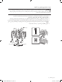
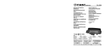
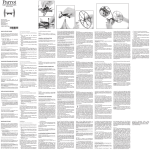
FTQ386LWUX FTQ352IWUX FTQ352IWUB FTQ352IWUW FCQ321HTUX FCQ321HTUB FCQ321HTUW FE-R300SX FE-R300SW FE-R300SB املوقد الكهربائي دليل التركيب إمكانيات هائلة نشكرك على شرائك هذا املنتج من .Samsung للحصول على املزيد من اخلدمات املتكاملة، الرجاء تسجيل املنتج اخلاص بك على www.samsung.com/global/register 6/12/2008 5:46:28 PM Installation-ZAM-DG68-00171A_AR.1 1 قبل البدء حول هذا الدليل اقرأ كافة هذه التعليمات بعناية. مالحظات هامة للقائم بالتركيب • اقرأ كافة التعليمات املذكورة ضمن إرشادات التركيب هذه قبل تركيب املوقد. • قم بإزالة كافة مواد التغليف من أجزاء الفرن قبل توصيل املوقد باملصدر الكهربائي. • االلتزام بكافة اللوائح والقوانني املنصوص عليها. • تأكد من ترك هذه التعليمات مع املستهلك. مالحظات هامة للمستهلك احتفظ بهذه التعليمات من أجل استخدامها من قبل متخصص الكهرباء. • عند استخدام أي جهاز يولد حرارة ،توجد احتياطات معينة تتعلق بالسالمة يجب إتباعها. • تأكد من تركيب املوقد وتوصيله بطرف أرضي بشكل صحيح بواسطة فني تركيب مؤهل أو فني صيانة مختص. • تأكد من إمكانية مقاومة أسطح اجلدر املوجودة حول املوقد للحرارة املو ّلدة من املوقد. • لتقليل احلاجة للوصول أعلى أجزاء السطح ،يجب عدم وجود فراغ كبير بني صندوق التخزين واألجزاء. ألغراض السالمة حتذير قد يحدث حريق أو صدمة كهربية ما لم يتم إتباع املعلومات املذكورة في هذا الدليل بالضبط مما قد يتسبب في إحلاق الضرر باملمتلكات أو حدوث إصابات جسدية أو الوفاة. حتذير قبل بدء التركيب ،قم بفصل التيار الكهربائي عن لوحة اخلدمة وتأمني وسائل فصل اخلدمة ملنع توصيل التيار الكهربائي فجأة. وإذا تعذر تأمني وسائل فصل اخلدمة ،قم بتثبيت جهاز حتذير بارز مثل عالمة على لوحة اخلدمة بشكل آمن. حتذير يجب توصيل هذا اجلهاز بطرف أرضي بشكل صحيح. أداة السند لتقليل مخاطر االنقالب ،يجب تأمني اجلهاز من خالل تركيب حامل أداة السند املرفقة مع هذا اجلهاز بشكل صحيح. حتذير • ميكن أن تتعرض كافة املواقد لالنقالب • ميكن أن تلحق اإلصابات باألشخاص • قم بتركيب حامل أداة السند املرفقة مع املوقد • راجع دليل التركيب إذا قمت بسحب املوقد بعي ًدا عن احلائط ألي سبب ،تأكد من تركيب حامل أداة السند عند إعادة املوقد مرة أخرى بجوار احلائط. قبل البدء _ 6/12/2008 5:46:28 PM Installation-ZAM-DG68-00171A_AR.2 2 اإلعداد لتركيب املوقد إزالة التغليف قم بإزالة مواد التغليف ميكن أن يتسبب عدم االلتزام بإزالة مواد التغليف في إتالف اجلهاز. إعداد األدوات واألجزاء مثقاب مفتاح ربط قابل للضبط زردية 1/4أداة ربط الصواميل مفك فيليبس مفك بحافة مستوية قلم رصاص ميزان 0 1اإلعداد لتركيب املوقد األدوات املطلوبة مرفقات املوقد دليل حامل أداة السند مسامير ()ea 2 األدوات غير املرفقة 4أو 3أسالك توصيل ( 40أو 50أمبير معتمدة من مختبرات الضمان ())UL أدوات تثبيت (لتركيب حاوية األسالك فقط) اإلعداد لتركيب املوقد _ 6/12/2008 5:46:30 PM Installation-ZAM-DG68-00171A_AR.3 3 فحص مكان التركيب املسافات واألبعاد لتركيب املوقد ،راجع الشكل التالي. للتركيب في كندا ،ال يجب تركيب موقد مستقل في مكان يبعد مسافة أقل من 12مم من أي سطح مجاور. تنبيه لقد مت تصميم هذا املوقد لكي يتماشي مع أقصي درجات احلرارة املسموح بها للخزانات اخلشبية التي تبلغ 194درجةفهرنهايت. تأكد من مقاومة أسطح اجلدر واألسطح األفقية واخلزانات املوجودة حول املوقد للحرارة (تصل إلى 194درجةفهرنهايت) التي يولدها الفرن .وإذا لم يتم ذلك ،فقد يحدث فقدان لأللوان أو تفتت األسطح إلى طبقات رقيقة أو تنصهر. ”3 ”3 ”25 ”24 (ب) ”6 (أ) ”36 (أ) :فتحة اخلزانة 30بوصة للواليات املتحدة األمريكية، ”30 ”24 30إلى 31بوصة بالنسبة لكندا. (ب) مكان منفذ كهربائي مناسب احلد األدنى لألبعاد هام لتقليل مخاطر اإلصابة باحلروق أو النيران التي حتدث نتيجة االقتراب من وحدات األسطح الساخنة ،يجب عدم وجود مسافة كبيرة بني خزانة التخزين ووحدات السطح التي بأسفلها .إذا كان هناك ضرورة الستخدام خزانة التخزين ،فيمكن تقليل اخملاطر بتركيب فتحة تهوية للموقد أفق ًيا تبعد حوالي 5بوصات كحد أدنى عن قاع اخلزانة. ”30 * ”30 ** ”15 * يجب توفر مسافة 30بوصة كحد أدنى بني أعلى سطح الطهي وقاع اخلزانة اخلشبية أو املعدنية غير احملمية؛ أو 24بوصة كحد أدنى عندما يكون قاع اخلزانة اخلشبية أو املعدنية مغطى بورق مقوى مقاوم لالشتعال يتراوح سمكه بني4/1بوصة ومغطى بصفائح حديد ليست أقل من 28 MSGأو حديد غير قابل للصدأ 0.015بوصة أو ألومنيوم 0.024أو نحاس .0.020 ** 15بوصة كحد أدنى بني السطح األفقي وقاع اخلزانة اجملاورة. اإلعداد لتركيب املوقد _ 6/12/2008 5:46:31 PM Installation-ZAM-DG68-00171A_AR.4 4 توصيل التيار الكهربائي اخلطوة .1 توفير متطلبات التوصيل الكهربائي تنبيه لتوفير السالمة الشخصية ،يحظر استخدام سلك متديد مع هذا اجلهاز .قم بإزالة سلك املنصهر اخلاص باملنزل أو فتح قاطع الدائرة الكهربائية قبل التركيب. 0 2توصيل الطاقة يجب تزويد اجلهاز بالفولطية والتردد املناسبني ،وتوصيله بدائرة فرعية أرضية بشكل صحيح ،وتزويد بقاطع دائرة كهربائية أو سلك منصهر بشدة تيار مطابقة ملا هو مذكور على لوحة التصنيف .توجد لوحة التصنيف أعلى الدرج على إطار الفرن( .الشكل 1أو الشكل )2 ينصح بتوصيل الوصالت كهربائية ومجموعة الدوائر الكهربائية اخلاصة باملوقد بواسطة كهربائي مؤهل .بعد التركيب ،اطلب من الكهربائي حتديد املكان الرئيسي لفصل الطاقة عن املوقد. تأكد من لوائح الكهرباء التي يتم تطبيقها في املنطقة التي تتبع لها من خالل إدارة الكهرباء احمللية .حيث قد يؤدي عدم االلتزام بتوصيل الفرن وفقًا للوائح املنصوص عليها إلى حدوث حاالت خطيرة .في حالة عدم وجود لوائح محلية ،يجب توصيل املوقد وتزويده بسلك منصهر مبا يتوافق مع متطلبات اللوائح الدولية للكهرباءANSI/NFPA ، رقم 70ـــ اإلصدار األخير .ميكنك احلصول على نسخة بإرسال طلب إلى: (الشكل )1 اجلمعية الدولية للوقاية من احلرائق Batterymarch Park Quincy, MA 02269 (الشكل )2 تقضي اللوائح القومية للكهرباء السارية اعتبارًا من 1يناير 1996باستخدام املنشئات اجلديدة (ليست القائمة) 4موصالت لتوصيل املوقد الكهربائي. اتبع اخلطوات 2و 3للتوصيل باستخدام 4أسالك عند تركيب موقد كهربائي في مبني جديد. يجب استخدام نظام كهربائي يتكون من ثالثة أسالك توصيل وتيار متردد أحادي الطور 120/208Y .فولت أو 120/240فولت وتردد 60هرتز. إذا لم تتطابق اخلدمة الكهربائية املوفرة مع املواصفات املوجودة أعاله ،اطلب من الكهربائي املتخصص تثبيت منفذ معتمد. استخدم سلك موقد به 3أو 4أطراف توصيل مذكورة ضمن قائمة اختبار الضمان ( )ULفقط .يجب جتميع هذه األسالك بحلقات دائرية حول السلك وأدوات تثبيت. يلزم توفير سلك موقد بشدة تيار 40أمبير وجهد 250/125فولت كحد أدنى .ال ينصح بسلك موقد شدة تياره 50أمبير ولكن إذا اضطررت الستخدامه ،يجب أن يستخدم مع فتحات التوصيل التي يصل قطرها إلى 13/8بوصة .يجب توخي احلذر عند وضع الكبل وأداة التثبيت داخل الفتحة اخملصصة له حتى ال يؤدي ذلك إلى تلف األسالك. • ونظرًا لعدم إمكانية الوصول إلى أطراف املوقد بعد وضعه في مكانه ،يجب استخدام حاوية أو سلك مرن. مالحظة في حالة استخدام احلاوية ،انتقل إلى اخلطوة 4في صفحة .9 تتطلب كافة منشآت الدوائر الكهربائية الفرعية اجلديدة ،واملنازل املتنقلة ،والسيارات الترفيهية والتركيبات سلك موقد موجود ضمن قائمة اختبار الضمان ( )ULحيث ال تسمح اللوائح احمللية بالتوصيل األرضي من خالل طرف محايد. توصيل الطاقة _ 6/12/2008 5:46:31 PM Installation-ZAM-DG68-00171A_AR.5 5 اخلطوة .2 الوصول إلى وصلة سلك التيار الكهربي قم بإزالة غطاء الوصول اخللفي وفك املسامير باستخدام مفك .عندئذ يسهل الوصول إلى صندوق األطراف. صندوق األطراف غطاء الوصول املواصفات احملددة جملموعة أسالك مصدر الكهرباء املواصفات ،الواط 3أسالك 240/120فولت 3أسالك 208/120فولت 16,500 - 8,750 12,500 - 7,801 املواصفات احملددة جملموعة أسالك مصدر الكهرباء ،وحدات أمبير 40أو 50أمبير قطر فتحة توصيل املوقد (بالبوصة) سلك الكهرباء احلاوية ”1 3/ 8 ”1 1/ 8 توصيل الطاقة _ 6/12/2008 5:46:32 PM Installation-ZAM-DG68-00171A_AR.6 6 اخلطوة .3 تركيب أسالك الكهرباء لتركيب سلك الكهرباء ،ضع أداة تثبيت أعلى فتحة سلك الكهرباء ( 13/8بوصة) املوجودة أسفل مؤخرة هيكل الدرج .مرر سلك الكهرباء من خالل أداة التثبيت ثم قم بشدها. لوحة توصيل احلاوية أداة التثبيت • 0 2توصيل الطاقة سلك الكهرباء يجب تركيب سلك الكهرباء باستخدام أدوات التثبيت. • قم بتركيب أداة التثبيت في فتحة لوحة توصيل احلاوية التي يبلغ قطرها 1 /8بوصة. 3 تركيب سلك كهرباء مكون من 3أطراف حتذير يجب توصيل السلك احملايد أو األرضي بسلك الكهرباء احملايد املوجود في منتصف صندوق األطراف .يجب توصيل أسالك التوصيل الكهربية باألطراف السفلية اليسرى واليمنى لصندوق األطراف. .1قم بإزالة مسامير ربط األطراف السفلية الثالثة من صندوق األطراف. .2قم بإدخال مسامير ربط األطراف الثالثة من خالل احللقة اخلاصة بكل طرف وأدخلها في األطراف السفلية لصندوق األطراف .تأكد من توصيل السلك األوسط (أبيض/محايد) باملوضع السفلي املتوسط لصندوق األطراف. ماسك أرضي طرف محايد أبيض أحمر أسود .3قم بربط املسامير بأمان في صندوق األطراف .يحظر إزالة املاسك األرضي. .4انتقل إلى خطوة 5في صفحة رقم 10وابدأ تنفيذ عملية التركيب. أحمر أبيض أسود توصيل الطاقة _ 6/12/2008 5:46:32 PM Installation-ZAM-DG68-00171A_AR.7 7 تركيب سلك كهرباء مكون من 4أطراف حتذير يجب توصيل السلك احملايد لدائرة مصدر الكهرباء بالطرف احملايد املوجود في اجلزء السفلي املتوسط لصندوق األطراف .يجب توصيل أسالك التوصيل الكهربية باألطراف السفلية اليسرى واليمنى لصندوق األطراف .يجب توصيل السلك الرصاصي األرضي الرابع بإطار املوقد باستخدام اللوحة ومسامير التثبيت باألرض. .1قم بإزالة مسامير ربط األطراف السفلية الثالثة من صندوق األطراف .قم بإزالة املسامير واللوحة األرضية واحتفظ بهم. .2اقطع املاسك األرضي وضعه جانبًا .يحظر التخلص من أي مسامير. .3أدخل املسمار األرضي األحادي في حلقة طرف السلك األرضي لسلك الكهرباء ،من خالل اللوحة األرضية ،وقم بإدخاله في إطار املوقد. .4قم بإدخال مسامير ربط األطراف الثالثة (التي مت إزالتها مسبقًا) من خالل احللقة اخلاصة بكل طرف وأدخلها في األطراف السفلية لصندوق األطراف .تأكد من توصيل السلك األوسط (أبيض/محايد) باملوضع السفلي املتوسط لصندوق األطراف .قم بربطاملسامير بأمان في صندوق األطراف. .5انتقل إلى خطوة 5في صفحة رقم 10وابدأ تنفيذ عملية التركيب. طرف محايد أبيض أسود أحمر ماسك أرضي لوحة أرضية أبيض سلك أرضي (أخضر) أحمر أسود مسامير أرضية توصيل الطاقة _ 6/12/2008 5:46:33 PM Installation-ZAM-DG68-00171A_AR.8 8 اخلطوة .4 تركيب احلاوية قم بإزالة لوحة توصيل احلاوية من خلفية هيكل الدرج وقم بتدويرها كما هو موضح أدناه. يجب استخدام فتحة احلاوية التي يبلغ قطرها (” 11/8بوصة). ”1 1/ 8 ”1 3/ 8 0 2توصيل الطاقة ”1 1/ 8 ”1 3/ 8 .1قم بإعداد سلك احلاوية املوضح في الشكل رقم .1 .2قم بتركيب سلك احلاوية كما هو موضح في الشكل رقم .2 شكل 2 حلقة هيكل ”/ 8 شكل 1 ” 3/ 8 ”1 3 ”3 1/ 2 ”1 ”3 1/ 2 3أسالك 4أسالك سطح التثبيت أداة التثبيت لوحة توصيل احلاوية لبدء عمليات تركيب احلاوية ،أدخل أداة التثبيت (غير مرفقة) في فتحة احلاوية التي قطرها (” 11/8بوصة) .ثم مرر سلك احلاوية من خالل أداة التثبيت وثبت احللقة .أعد تركيب احلامل. تركيب حاوية مكونة من 3أطراف • ميكن استخدام سلك مصنوع من األلومنيوم ولكن يجب أن يحقق شدة التيار والفولطية املطلوبة لتحقيق االتصال .قم بتوصيل األسالك وفقًا للخطوة رقم 4التي تعتمد على عدد األسالك. • يجب مطابقة السلك املستخدم ومكان وصالت األطراف املتراكبة والغالف اخلارجي لها ،الخ مع مواصفات التوصيل اجليد واللوائح احمللية. .1قم بفك مسامير ربط األطراف السفلية الثالثة من صندوق األطراف. .2أدخل طرف السلك املكشوف األوسط (أبيض/محايد) من خالل فتحة صندوق األطراف السفلية الوسطى .سوف يحتاج السلك إلى إدخاله من خالل فتحة املاسك األرضي ثم إدخاله في فتحة الصندوق السفلية الوسطي مع طرازات معينة. ماسك أرضي طرف محايد أبيض أسود أحمر .3أدخل فتحتي السلك املكشوف اجلانبيتني في فتحات صندوق األطراف السفلية اليسرى واليمنى. .4قم بربط املسامير بإحكام حتى يتم تأمني السلك بدرجة كافية ( 35إلى 50بوصة-رطل) .ال تفرط في ربط املسامير حيث أن ذلك قد يؤدى إلى تلف األسالك. .5انتقل إلى خطوة 5في صفحة رقم 10وابدأ تنفيذ عملية التركيب. أحمر أبيض أسود أطراف السلك توصيل الطاقة _ 6/12/2008 5:46:34 PM Installation-ZAM-DG68-00171A_AR.9 9 تركيب حاوية مكونة من 4أطراف • ميكن استخدام سلك مصنوع من األلومنيوم ولكن يجب أن يحقق شدة التيار والفولطية املطلوبة لتحقيق االتصال .قم بتوصيل األسالك وفقًا للخطوة 4التي تعتمد على عدد األسالك. • يجب مطابقة السلك املستخدم ومكان وصالت األطراف املتراكبة والغالف اخلارجي لها ،إلخ مع مواصفات التوصيل اجليد واللوائح احمللية. .1قم بفك مسامير ربط األطراف السفلية الثالثة من صندوق األطراف .قم بإزالة املسامير واللوحة األرضية واحتفظ بهم. .2اقطع املاسك األرضي وضعه جانبًا .يحظر التخلص من أي مسامير. .3أدخل طرف السلك األرضي املكشوف بني إطار املوقد واللوحة األرضية (التي متت إزالتها مسبقًا) وقم بتأمينها في مكان مع املسمار األرضي (التي متت إزالته مسبقًا). .4أدخل طرف السلك املكشوف (أبيض/محايد) من خالل فتحة صندوق األطراف السفلية. .5أدخل فتحتي السلك املكشوف اجلانبيتني في فتحات صندوق األطراف السفلية اليسرى واليمنى. .6قم بربط املسامير بإحكام حتىيتم تأمني السلك بدرجة كافية ( 35إلى 50بوصة-رطل) .ال تفرط في ربط املسامير حيث أن ذلك قد يؤدى إلى تلف األسالك. .7انتقل إلى خطوة 5وابدأ تنفيذ عملية التركيب. طرف محايد أحمر أبيض أسود ماسك أرضي لوحة أرضية سلك أرضي (أخضر) اخلطوة .5 أحمر أطراف السلك أبيض أسود استبدال غطاء الوصول استبدل غطاء الوصول املوجود على مؤخرة املوقد .الستبدال غطاء السلك ،قم بإدخال األجزاء الناتئة املزدوجة في احلافظات املوجودة أسفل الفتحة وقم بربط املسامير. توصيل الطاقة _10 6/12/2008 5:46:35 PM Installation-ZAM-DG68-00171A_AR.10 10 تركيب املوقد تركيب أداة السند حتذير للحد من خطورة االنقالب ،يجب تأمني اجلهاز بشكل صحيح بتركيب أداة السند املرفقة مع اجلهاز. • قد ينقلب املوقد عند وضع القدم على الباب أو اجللوس عليه ،ما لم يتم تركيبه بشكل صحيح .وقد حتدث إصابات من السوائل الساخنة املسكوبة أو من املوقد ذاته. حامل أداة السند 0 3تركيب املوقد • راجع إرشادات التركيب املرفقة مع احلامل. *تقري ًبا 32/21بوصة ( 16.5مم) يجب تثبيت املسامير في سطح خشبي أو خرساني *مالحظة :لتركيب حامل أداة السند ،قم بتحرير قائم ضبط االستواء .يجب ترك مسافة تقدر بـ 32/21بوصة (16.5مم) على األقل بني أسفل املوقد وأرضية املطبخ. .1حدد مكان احلامل باستخدام الدليل يتم إرفاق حامل أداة السند مع دليل خاص بها .تتضمن اإلرشادات املعلومات الالزمة الستكمال عملية التركيب .أقرأ اإلرشادات املوجودة في الورقة (الدليل) اخلاص بتركيب املوقد وقم بإتباعها. .2حتديد مستوى املوقد حدد مستوى الفرن بضبط قوائم استواء السطح باستخدام مفتاح ربط. زيادة مستوى ارتفاع املوقد قوائم ضبط استواء السطح خفض مستوى ارتفاع املوقد تركيب املوقد _11 6/12/2008 5:46:35 PM Installation-ZAM-DG68-00171A_AR.11 11 .3تأكد من عمليات ضبط السطح استخدم ميزان التسوية للتأكد من عمليات ضبط السطح .ضع امليزان بشكل قطري على حامل الفرن ،وتأكد من كل اجتاه لتحديد املستوى. .1تأكد من االجتاه رقم .1 .2تأكد من االجتاه رقم .2 إذا لم يوضح ميزان التسوية مستوى الضبط على احلامل ،قم بضبط قوائم ضبط االستواء باستخدام مفتاح ربط. إنهاء عملية التركيب • قم بتحريك املوقد بالقرب من الفتحة بدرجة كافية لتركيبه في املقبس. • انقل املوقد إلى مكانه مما يضمن أن الرجل اخللفية اليسرى (أو اخللفية اليمنى) تنزلق حتت حامل أداة السند .لن تكون هناك مسافة بني املوقد واجلدار اخللفي عندما يتم تركيب املوقد بشكل صحيح. • قم بتحريك املوقد بحرص لألمام لضمان تثبيت حامل أداة السند بالدعامة اخللفية ومنع االنقالب. • قم بتشغيل التيار الكهربي .تأكد من تشغيل املوقد بشكل صحيح كما هو موضح في دليل املستخدم. حامل أداة السند قوائم ضبط استواء السطح DG68-00171B تركيب املوقد _12 6/12/2008 5:46:36 PM Installation-ZAM-DG68-00171A_AR.12 12 FTQ386LWUX FTQ352IWUX FTQ352IWUB FTQ352IWUW FCQ321HTUX FCQ321HTUB FCQ321HTUW FE-R300SX FE-R300SW FE-R300SB Electric Range installation manual imagine the possibilities Thank you for purchasing this Samsung product. To receive more complete service, please register your product at www.samsung.com/global/register Installation-SAUDI DG68-00171B.indd 1 2010-05-17 �� 6:07:46 before you begin About this manual READ THESE INSTRUCTIONS COMPLETELY AND CAREFULLY. Important note to the installer • Read all instructions contained in these installation instructions before installing range. • Remove all packing materials from the oven compartments before connecting the electrical supply to the range. • Observe all governing codes and ordinances. • Be sure to leave these instructions with the consumer. Important note to the consumer Keep these instructions for the local electrical inspector’s use. • As when using any appliance generating heat, there are certain safety precautions you should follow. • Be sure your range is installed and grounded properly by a qualified installer or service technician. • Make sure the wall coverings around the range can withstand the heat generated by the range. • To eliminate the need to reach over the surface elements, cabinet storage space above the elements should be avoided. FOR YOUR SAFETY WARNING If the information in this manual is not followed exactly, a fire or electrical shock may result causing property damage, personal injury or death. WARNING Before beginning the installation, switch power off at the service panel and lock the service disconnecting means to prevent power from being switched on accidentally. When the service disconnecting means cannot be locked, securely fasten a prominent warning device, such as a tag, to the service panel. WARNING This appliance must be properly grounded. ANTI-TIP DEVICE TO REDUCE THE RISK OF TIPPING, THE APPLIANCE MUST BE SECURED BY PROPERLY INSTALLING THE ANTI-TIP BRACKET PROVIDED WITH THIS APPLIANCE. WARNING • ALL RANGES CAN TIP • INJURY TO PERSONS COULD RESULT • INSTALL ANTI-TIP BRACKET PACKED WITH RANGE • SEE INSTALLATION MANUAL If you pull the range out and away from the wall for any reason, make sure the Anti-Tip bracket is engaged when the range is pushed back against the wall. 2_ Before you begin Installation-SAUDI DG68-00171B.indd 2 2010-05-17 �� 6:07:47 preparing to install the range REMOVE PACKAGING Remove packaging materials. Failure to remove packaging materials could result in damage to the appliance. PREPARE TOOLS & PARTS Drill Adjustable Wrench Pliers Phillips Screwdriver Flat Screwdriver Pencil 1/4˝ Nut Driver 01 PREPARING TO INSTALL What tools you will need Level What’s included with your range Template Anti-Tip Bracket Screws (2 ea) What’s not included 4-Wire Cord or 3-Wire Cord (UL Approved 40 or 50 AMP) Strain Relief (For Conduit Installation Only) Preparing to install the range _3 Installation-SAUDI DG68-00171B.indd 3 2010-05-17 �� 6:07:47 CHECKING THE INSTALLATION SITE Clearances and dimensions To install the range, refer to the following figure. For installation in CANADA, a Free-standing range is not to be installed closer than 12mm from any adjacent surface. CAUTION This range has been designed to comply with the maximum allowable wood cabinet temperatures of 194°F. Make sure the wall covering, countertops and cabinets around the range can withstand the heat (up to 194°F) generated by the range. If not, discoloration, delamination or melting may occur. 3” 25” 24” 6” 36” 3” B A A : Cabinet opening 30” For U.S.A, 30”~31” For CANADA. 30” 24” B : Acceptable electrical outlet area Minimum dimensions IMPORTANT To eliminate the risk of burns or fire caused by reaching over heated surface units, cabinet storage space located above the surface units should be avoided. If cabinet storage is to be provided, the risk can be reduced by installing a range hood that projects horizontally a minimum of 5” beyond the bottom of the cabinets. 30” * 30” ** 15” * 30” minimum clearance between the top of the cooking surface and the bottom of an unprotected wood or metal cabinet; or 24” minimum when the bottom of the wood or metal cabinet is protected by not less than 1/4” flame retardant millboard covered with not less than no.28 MSG sheet steel, 0.015” stainless steel, 0.024” aluminum or 0.020” copper. ** 15” minimum between the countertop and the adjacent cabinet bottom. 4_ Preparing to install the range Installation-SAUDI DG68-00171B.indd 4 2010-05-17 �� 6:07:47 connecting the power STEP 1.MEETING ELECTRICAL CONNECTION REQUIREMENTS CAUTION For personal safety, do not use an extension cord with this appliance. Remove house fuse or open circuit breaker before beginning installation. 02 CONNECTING THE POWER This appliance must be supplied with the proper voltage and frequency, and connected to an individual properly grounded branch circuit, protected by a circuit breaker or fuse having amperage as specified on the rating plate. The rating plate is located above the drawer on the oven frame. (Fig. 1 or Fig. 2) We recommend you have the electrical wiring and hookup of your range connected by a qualified electrician. After installation, have the electrician show you where your main range disconnect is located. Check with your local utilities for electrical codes which apply in your area. Failure to wire your oven according to governing codes could result in a hazardous condition. If there are no local codes, your range must be wired and fused to meet the requirements of the National Electrical Code, ANSI/NFPA No. 70–Latest Edition. You can get a copy by writing: (Fig. 1) National Fire Protection Association Batterymarch Park Quincy, MA 02269 (Fig. 2) Effective January 1, 1996, the National Electrical Code requires that new construction (not existing) utilize a 4-conductor connection to an electric range. When installing an electric range in new construction, follow Steps 2 and 3 for 4-wire connection. You must use a 3-wire, single-phase A.C. 208Y/120 Volt or 240/120 Volt, 60 hertz electrical system. If the electrical service provided does not meet the above specifications, have a licensed electrician install an approved outlet. Use only a 3-conductor or a 4-conductor UL-listed range cord. These cords may be provided with ring terminals on wire and a strain relief device. A range cord rated at 40 amps with 125/250 minimum volt range is required. A 50 amp range cord is not recommended but if used, it should be marked for use with nominal 13⁄8” diameter connection openings. Care should be taken to center the cable and strain relief within the knockout hole to keep the edge from damaging the cable. • Because range terminals are not accessible after range is in position, flexible service conduit or cord must be used. NOTE If conduit is being used, go to Step 4 on page 9. ALL NEW BRANCH-CIRCUIT CONSTRUCTIONS, MOBILE HOMES, RECREATIONAL VEHICLES AND INSTALLATIONS WHERE LOCAL CODES DO NOT ALLOW GROUNDING THROUGH NEUTRAL, REQUIRE A 4-CONDUCTOR UL-LISTED RANGE CORD. Connecting the power _5 Installation-SAUDI DG68-00171B.indd 5 2010-05-17 �� 6:07:48 STEP 2. ACCESSING THE POWER CORD CONNECTION Remove the rear access cover and loosen the screw with a screwdriver. The terminal block will then be accessible. Terminal block Access cover Specified power-supply-cord kit rating Range rating, watts 120/240 volts 3-wire 120/208 volts 3-wire 8,750 - 16,500 7,801 - 12,500 Diameter (inches) of range connection opening Specified rating of power-supply-cord kit, amperes Power cord Conduit 40 or 50A 13/8” 11/8” 6_ Connecting the power Installation-SAUDI DG68-00171B.indd 6 2010-05-17 �� 6:07:48 STEP 3.INSTALLING THE POWER CORD For power cord installations, hook the strain relief over the power cord hole (13/8”) located below the rear of the drawer body. Insert the power cord through the strain relief and tighten the device. Conduit connection plate Power cord 02 CONNECTING THE POWER Strain relief • You must install the power cord with a strain relief. • Attach the strain relief to the 13/8” opening in conduit connection plate. Installing a 3-wire power cord WARNING The neutral or ground wire of the power cord must be connected to the neutral terminal located in the center of the terminal block. The power leads must be connected to the lower left and the lower right terminals of the terminal block. 1. Remove the 3 lower terminal screws from the terminal block. 2. Insert the 3 terminal screws through each power cord terminal ring and into the lower terminals of the terminal block. Be certain that the center wire (white/neutral) is connected to the center lower position of the terminal block. Ground strap Neutral terminal White Black Red 3. Tighten screws securely into the terminal block. DO NOT remove the ground strap connection. 4. Go to step 5 on page 10 and proceed with the installation. Black White Red Connecting the power _7 Installation-SAUDI DG68-00171B.indd 7 2010-05-17 �� 6:07:48 Installing a 4-wire power cord WARNING The neutral wire of the supply circuit must be connected to the neutral terminal located in the lower center of the terminal block. The power leads must be connected to the lower left and the lower right terminals of the terminal block. The 4th grounding lead must be connected to the frame of the range with the ground plate and the ground screw. 1. Remove the 3 lower terminal screws from the terminal block. Remove the ground screw and ground plate and retain them. 2. Cut and discard the ground strap. Do not discard any screws. 3. Insert the one ground screw into the power cord ground wire terminal ring, through the ground plate, and into the frame of the range. 4. Insert the 3 terminal screws (removed earlier) through each power cord terminal ring and into the lower terminals of the terminal block. Be certain that the center wire (white/neutral) is connected to the center lower position of the terminal block. Tighten screws securely into the terminal block. 5. Go to step 5 on page 10 and proceed with the installation. Neutral terminal White Black Red Ground strap Ground plate Black Ground screw White Red Ground wire (Green) 8_ Connecting the power Installation-SAUDI DG68-00171B.indd 8 2010-05-17 �� 6:07:48 STEP 4.INSTALLING THE CONDUIT Remove the conduit connection plate from the rear of the drawer body and rotate it as shown below. The conduit hole (11/8”) must be used. 11/8” 13/8” 13/8” 11/8” 2. Install the conduit cord as shown in Figure 2. Figure 1 3/8” 1” Figure 2 3/8” 1” 31/2” 3 wire Ring Body 31/2” 4 wire Knockout surface Strain relief 02 CONNECTING THE POWER 1. Prepare the conduit cord shown in Figure 1. Conduit connection plate For conduit installations, insert the strain relief (not included) into the conduit hole (11/8”). Then thread the conduit cord through the body of the strain relief and fasten the ring. Reinstall the bracket. Installing a 3-wire conduit • Aluminum building wire may be used but it must be rated for the correct amperage and voltage to make the connection. Connect wires according to Step 4 depending on the number of wires. • Wire used, location and enclosure of splices, etc., must conform to good wiring practices and local codes. 1. Loosen the 3 lower terminal screws from the terminal block. 2. Insert the center bare wire (white/neutral) tip through the bottom center terminal block opening. On certain models, the wire will need to be inserted through the ground strap opening and then into the bottom center block opening. Neutral terminal White Black Ground strap Red 3. Insert the two side bare wire tips into the lower left and the lower right terminal block openings. 4. Tighten the screws until the wire is firmly secured (35 to 50 inch-lbs.). Do not over-tighten the screws since it could damage the wires. 5. Go to step 5 on page 10 and proceed with the installation. Black White Red Wire tips Connecting the power _9 Installation-SAUDI DG68-00171B.indd 9 2010-05-17 �� 6:07:49 Installing a 4-wire conduit • Aluminum building wire may be used but it must be rated for the correct amperage and voltage to make the connection. Connect wires according to this Step 4 depending on the number of wires. • Wire used, location and enclosure of splices, etc., must conform to good wiring practices and local codes. 1. Loosen the 3 lower terminal screws from the terminal block. Remove the ground screw and ground plate and retain them. 2. Cut and discard the ground strap. Do not discard any screws. 3. Insert the ground bare wire tip between the range frame and the ground plate (removed earlier) and secure it in place with the ground screw (removed earlier). 4. Insert the bare wire (white/neutral) tip through the bottom center of the terminal block opening. 5. Insert the two side bare wire tips into the lower left and the lower right terminal block openings. 6. Tighten the screws until the wire is firmly secured (35 to 50 inch-lbs.). Do not over-tighten the screws since it could damage the wires. 7. Go to step 5 and proceed with the installation. Black Red White Neutral terminal Ground strap Ground plate Wire tips White Black Red Ground wire (Green) STEP 5. REPLACING THE ACCESS COVER Replace the access cover on the range back. To replace the wire cover, insert double projections in the pockets located below the opening and tighten the screw. 10_ Connecting the power Installation-SAUDI DG68-00171B.indd 10 2010-05-17 �� 6:07:49 installing the range INSTALLING THE ANTI-TIP DEVICE WARNING To reduce the risk of tipping, the appliance must be secured by properly installing the Anti-Tip device packed with the appliance. • Refer to the installation instructions supplied with the bracket. Anti-Tip bracket *approximately 21/32”(16.5mm) *NOTE: To install Anti-Tip bracket, release the leveling leg. A minimum clearance of 21/32”(16.5mm) is required between the range bottom and the kitchen floor. Screw must enter wood or concrete 03 INSTALLING THE RANGE • Unless properly installed, the range could be tipped by stepping or sitting on the door. Injury may result from spilled hot liquids or from the range itself. 1.Locate the bracket using the template The Anti-Tip bracket is packaged with a template. The instructions include information necessary to complete the installation. Read and follow the instructions on the sheet (template) for range installation. 2.Level the range Level the range by adjusting the leveling legs with a wrench. Raise range Lower range Leveling leg Installing the range _11 Installation-SAUDI DG68-00171B.indd 11 2010-05-17 �� 6:07:50 3.Check your adjustments Use a spirit level to check your adjustments. Place the level diagonally on the oven rack, and check each direction for level. 1. Check direction 1. 2. Check direction 2. If the spirit level doesn’t show level on the rack, adjust the leveling legs with a wrench. FINALIZING THE INSTALLATION • Move range close enough to the opening to plug into the receptacle. • Slide range into position insuring that the rear left(or rear right) leg slides under the Anti-Tip bracket. The range will sit 0” away from the back wall when properly installed. • Carefully tip the range forward to insure that the Anti-Tip bracket engages the back brace and prevents tip-over. • Turn on the electrical power. Check the range for proper operation as described in the user manual. Anti-Tip bracket Leveling leg DG68-00171B 12_ Installing the range Installation-SAUDI DG68-00171B.indd 12 2010-05-17 �� 6:07:50