1
Features of your new air conditioner
Turbo function
You can set the Turbo function to provide fast and powerful cooling (heating).
Easy Filter
There is no grille to remove before separating the filter from the air conditioner! Therefore, filter can
be cleaned easily, more frequently! Frequent filter cleaning will prevent dust from entering into the
product or accumulating on the filter.
function
function will allow you to have deep, good night’s sleep by adjusting the
temperature, fan speed and air flow direction.
Easy Installation
It’s so easy to install! You can easily hang the product on the wall and connect the pipes and wires
by opening the cover on the bottom of the product. Now you won’t have to tilt the product to
connect the pipe and the wires!
This product has been determined to be in compliance with the Low Voltage Directive (2006/95/EC), the Electromagnetic Compatibility
Directive (2004/108/EC) and the Machinery Directive (2006/42/EC) of the European Union.
Correct Disposal of This Product
(Waste Electrical & Electronic Equipment)
(Applicable in countries with separate collection systems)
This marking on the product, accessories or literature indicates that the product and its electronic accessories (e.g. charger, headset, USB cable) should not be
disposed of with other household waste at the end of their working life. To prevent possible harm to the environment or human health from uncontrolled
waste disposal, please separate these items from other types of waste and recycle them responsibly to promote the sustainable reuse of material resources.
Household users should contact either the retailer where they purchased this product, or their local government office, for details of where and how
they can take these items for environmentally safe recycling.
Business users should contact their supplier and check the terms and conditions of the purchase contract. This product and its electronic accessories
should not be mixed with other commercial wastes for disposal.
English-2
Contents
Preparation
Safety precautions . . . . . . . . . . . . . . . . . . . . . . . . . . . . . . . . . . . . . . . . . . . . . . . . . . . . . . . . . . . . . . . . . . . . . . . . . . . . . . . . . . . . . . . . . . . . . . . . . . . . . . . . . . 4
Checking before use . . . . . . . . . . . . . . . . . . . . . . . . . . . . . . . . . . . . . . . . . . . . . . . . . . . . . . . . . . . . . . . . . . . . . . . . . . . . . . . . . . . . . . . . . . . . . . . . . . . . . . . 10
Checking the name of the parts . . . . . . . . . . . . . . . . . . . . . . . . . . . . . . . . . . . . . . . . . . . . . . . . . . . . . . . . . . . . . . . . . . . . . . . . . . . . . . . . . . . . . . . . . . . . 11
Using the remote controller . . . . . . . . . . . . . . . . . . . . . . . . . . . . . . . . . . . . . . . . . . . . . . . . . . . . . . . . . . . . . . . . . . . . . . . . . . . . . . . . . . . . . . . . . . . . . . . . 12
Basic operation
Basic operation . . . . . . . . . . . . . . . . . . . . . . . . . . . . . . . . . . . . . . . . . . . . . . . . . . . . . . . . . . . . . . . . . . . . . . . . . . . . . . . . . . . . . . . . . . . . . . . . . . . . . . . . . . . . 15
Timer
Setting the On/Off timer . . . . . . . . . . . . . . . . . . . . . . . . . . . . . . . . . . . . . . . . . . . . . . . . . . . . . . . . . . . . . . . . . . . . . . . . . . . . . . . . . . . . . . . . . . . . . . . . . . . 18
Setting the good'sleep mode . . . . . . . . . . . . . . . . . . . . . . . . . . . . . . . . . . . . . . . . . . . . . . . . . . . . . . . . . . . . . . . . . . . . . . . . . . . . . . . . . . . . . . . . . . . . . . 20
Options
Using the Turbo function . . . . . . . . . . . . . . . . . . . . . . . . . . . . . . . . . . . . . . . . . . . . . . . . . . . . . . . . . . . . . . . . . . . . . . . . . . . . . . . . . . . . . . . . . . . . . . . . . . 22
Using the Purity function . . . . . . . . . . . . . . . . . . . . . . . . . . . . . . . . . . . . . . . . . . . . . . . . . . . . . . . . . . . . . . . . . . . . . . . . . . . . . . . . . . . . . . . . . . . . . . . . . . 23
Settings
Selecting an indoor unit . . . . . . . . . . . . . . . . . . . . . . . . . . . . . . . . . . . . . . . . . . . . . . . . . . . . . . . . . . . . . . . . . . . . . . . . . . . . . . . . . . . . . . . . . . . . . . . . . . . 24
Selecting a blade . . . . . . . . . . . . . . . . . . . . . . . . . . . . . . . . . . . . . . . . . . . . . . . . . . . . . . . . . . . . . . . . . . . . . . . . . . . . . . . . . . . . . . . . . . . . . . . . . . . . . . . . . . 24
Others
Cleaning the air conditioner . . . . . . . . . . . . . . . . . . . . . . . . . . . . . . . . . . . . . . . . . . . . . . . . . . . . . . . . . . . . . . . . . . . . . . . . . . . . . . . . . . . . . . . . . . . . . . . 25
Maintaining the air conditioner . . . . . . . . . . . . . . . . . . . . . . . . . . . . . . . . . . . . . . . . . . . . . . . . . . . . . . . . . . . . . . . . . . . . . . . . . . . . . . . . . . . . . . . . . . . . 28
Troubleshooting . . . . . . . . . . . . . . . . . . . . . . . . . . . . . . . . . . . . . . . . . . . . . . . . . . . . . . . . . . . . . . . . . . . . . . . . . . . . . . . . . . . . . . . . . . . . . . . . . . . . . . . . . . . 29
Appendix . . . . . . . . . . . . . . . . . . . . . . . . . . . . . . . . . . . . . . . . . . . . . . . . . . . . . . . . . . . . . . . . . . . . . . . . . . . . . . . . . . . . . . . . . . . . . . . . . . . . . . . . . . . . . . . . . . 31
Installation parts
Installation parts . . . . . . . . . . . . . . . . . . . . . . . . . . . . . . . . . . . . . . . . . . . . . . . . . . . . . . . . . . . . . . . . . . . . . . . . . . . . . . . . . . . . . . . . . . . . . . . . . . . . . . . . . . . 32
English-3
Safety precautions
Before using your new air conditioner, please read this manual thoroughly to ensure
that you know how to safely and efficiently operate the extensive features and
functions of your new appliance.
Because the following operating instructions cover various models, the
characteristics of your air conditioner may differ slightly from those described in this
manual. If you have any questions, call your nearest contact center or find help and
information online at www.samsung.com.
Important safety symbols and precautions:
WARNING
CAUTION
Hazards or unsafe practices that may result in severe
personal injury or death.
Hazards or unsafe practices that may result in minor
personal injury or property damage.
Follow directions.
Cut-off the power supply.
Do NOT attempt.
Do NOT disassemble.
Make sure the machine is grounded to prevent electric shock.
FOR INSTALLATION
WARNING
Use the power line with the power specifications of the product or higher
and use the power line for this appliance only. In addition, do not use an
extension line.
Extending the power line may result in electric shock or fire.
Do not use an electric transformer. It may result in electric shock or fire.
If the voltage/frequency/rated current condition is different, it may cause fire.
The installation of this appliance must be performed by a qualified
technician or service company.
Failing to do so may result in electric shock, fire, explosion, problems with the
product, or injury and may also void warranty on the installed product.
Install a Isolation Switch next to the Air Conditioner (but not on the panels
of the Air Conditioner)and circuit breaker dedicated to the air conditioner.
Failing to do so may result in electric shock or fire.
Fix the outdoor unit firmly so that the electric part of the outdoor unit is not
exposed.
Failing to do so may result in electric shock, fire, explosion, problems with the
product.
English-4
FOR INSTALLATION
CAUTION
Install your appliance on a level and hard floor that can support its weight.
Failing to do so may result in abnormal vibrations, noise, or problems with the
product.
Install the draining hose properly so that water is drained correctly.
Failing to do so may result in water overflowing and property damage. Avoid
adding drain to waste pipes as odours may arise in the future.
When installing the outdoor unit, make sure to connect the draining hose
so that draining is performed correctly.
The water generated during the heating operation by the outdoor unit may
overflow and result in property damage.
In particular, in winter, if a block of ice falls, it may result in injury, death or
property damage.
FOR POWER SUPPLY
WARNING
When the circuit breaker is damaged, contact your nearest service center.
Do not pull or excessively bend the power line. Do not twist or tie the
power line. Do not hook the power line over a metal object, place a heavy
object on the power line, insert the power line between objects, or push
the power line into the space behind the appliance.
This may result in electric shock or fire.
English-5
01 PREPARATION
Do not install this appliance near a heater, inflammable material. Do
not install this appliance in a humid, oily or dusty location, in a location
exposed to direct sunlight and water (rain drops). Do not install this
appliance in a location where gas may leak.
This may result in electric shock or fire.
Never install the outdoor unit in a location such as on a high external wall
where it could fall.
If the outdoor unit falls, it may result in injury, death or property damage.
This appliance must be properly grounded. Do not ground the appliance to a
gas pipe, plastic water pipe, or telephone line.
Failure to do so may result in electric shock, fire, and explosion.
Make sure to use a socket-outlet with ground.
Safety precautions
FOR POWER SUPPLY
CAUTION
When not using the air conditioner for a long period of time or during a
thunder/lightning storm, cut the power at the circuit breaker.
Failing to do so may result in electric shock or fire.
FOR USING
WARNING
If the appliance is flooded, please contact your nearest service center.
Failing to do so may result in electric shock or fire.
If the appliance generates a strange noise, a burning smell or smoke, cutoff the power supply immediately and contact the nearest service center.
Failing to do so may result in electric shock or fire.
In the event of a gas leak (such as propane gas, LP gas, etc.), ventilate
immediately without touching the power line. Do not touch the appliance
or power line.
Do not use a ventilating fan.
A spark may result in an explosion or fire.
To reinstall the air conditioner, please contact your nearest service center.
Failing to do so may result in problems with the product, water leakage,
electric shock, or fire.
A delivery service for the product is not provided. If you reinstall the product in
another location, additional construction expenses and an installation fee will
be charged.
Especially, when you wish to install the product in an unusual location such as
in an industrial area or near the seaside where it is exposed to the salt in the air,
please contact your nearest service center.
Do not touch the circuit breaker with wet hands.
This may result in electric shock.
Do not turn the air conditioner off with the circuit breaker while it is
operating.
Turning the air conditioner off and then on again with the circuit breaker may
cause a spark and result in electric shock or fire.
After unpacking the air conditioner, keep all packaging materials well
out of the reach of children, as packaging materials can be dangerous to
children.
If a child places a bag over its head, it may result in suffocation.
English-6
FOR USING
WARNING
Do not place an object near the outdoor unit that allows children to climb
onto the machine.
This may result in children seriously injuring themselves.
Do not use this air conditioner for long periods of time in badly ventilated
locations or near infirm people.
Since this may be dangerous due to a lack of oxygen, Open a window at least
once an hour.
If any foreign substance such as water has entered the appliance, cut-off
the power supply and contact the nearest service center.
Failing to do so may result in electric shock or fire.
Do not attempt to repair, disassemble, or modify the appliance yourself.
Do not use any fuse (such as cooper, steel wire, etc.)other than the standard
fuse.
Failing to do so may result in electric shock, fire, problems with the product, or
injury.
English-7
01 PREPARATION
Do not insert your fingers or foreign substances into the outlet when the air
conditioner is operating.
Take special care that children do not injure themselves by inserting their
fingers into the product.
Do not touch the air flow blade with your hands or fingers during the
heating operation.
This may result in electric shock or burns.
Do not insert your fingers or foreign substances into the air inlet/outlet of
the air conditioner.
Take special care that children do not injure themselves by inserting their
fingers into the product.
Do not strike or pull the air conditioner with excessive force.
This may result in fire, injury, or problems with the product.
Safety precautions
FOR USING
CAUTION
Do not place objects or devices under the indoor unit.
Water dripping from the indoor unit may result in fire or property damage.
(example electrical appliances)
Check that the installation frame of the outdoor unit is not broken at least
once a year.
Failing to do so may result in injury, death or property damage.
Max current is measured according to IEC standard for safety and current is
measured according to ISO standard for energy efficiency.
Do not stand on top of the appliance or place objects (such as laundry,
lighted candles, lighted cigarettes, dishes, chemicals, metal objects, etc.) on
the appliance.
This may result in electric shock, fire, problems with the product, or injury.
Do not operate the appliance with wet hands.
This may result in electric shock.
Do not spray volatile material such as insecticide onto the surface of the
appliance.
As well as being harmful to humans, it may also result in electric shock, fire or
problems with the product.
Do not drink the water from the air conditioner.
The water may be harmful to humans.
Do not apply a strong impact to the remote controller and do not
disassemble the remote controller.
Do not touch the pipes connected with the product.
This may result in burns or injury.
Do not use this air conditioner to preserve precision equipment, food,
animals, plants or cosmetics, or for any other unusual purposes.
This may result in property damage.
Avoid directly exposing humans, animals or plants from the air flow from
the air conditioner for long periods of time.
This may result in harm to humans, animals or plants.
English-8
FOR CLEANING
WARNING
Do not clean the appliance by spraying water directly onto it. Do not use
benzene, thinner or alcohol to clean the appliance.
This may result in discoloration, deformation, damage, electric shock or fire.
Before cleaning or performing maintenance, cut-off the power supply and
wait until the fan stops.
Failing to do so may result in electric shock or fire.
FOR CLEANING
CAUTION
Take care when cleaning the surface of the heat exchanger of the outdoor
unit since it has sharp edges.
This should be done by a qualified technician please contact your installer or
service center.
Do not clean the inside of the air conditioner by yourself.
For cleaning inside the appliance, contact your nearest service center.
When cleaning the internal filter, refer to the descriptions in the ‘Cleaning the
air conditioner’ section.
Failure to do may result in damage, electric shock or fire.
English-9
01 PREPARATION
This appliance is not intended for use by persons (including children) with
reduced physical, sensory or mental capabilities, or lack of experience
and knowledge, unless they have been given supervision or instruction
concerning use of the appliance by a person responsible for their safety.
Children should be supervised to ensure that they do not play with the
appliance.
For use in Europe : This appliance can be used by children aged from 8
years and above and persons with reduced physical, sensory or mental
capabilities or lack of experience and knowledge if they have been given
supervision or instruction concerning use of the appliance in a safe way
and understand the hazards involved. Children shall not play with the
appliance. Cleaning and user maintenance shall not be made by children
without supervision.
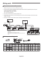
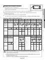
Checking before use
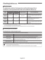
Operation ranges
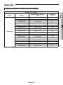
The table below indicates the temperature and humidity ranges the air
conditioner can be operated within. Refer to the table for efficient use.
OPERATIONAL TEMPERATURE
MODE
INDOOR HUMIDITY
IF OUT OF CONDITIONS
-5˚C to 48˚
80% or less
Condensation may occur on the indoor unit
with risk to have either water blow off or drops
on the floor.
27˚C or less
-20˚C to 24˚C
-
Internal protection triggers and the air
conditioner will stop.
16˚C to 32˚C
-5˚C to 48˚C
-
Condensation may occur on the indoor unit
with risk to have either water blow off or drops
on the floor.
INDOOR
OUTDOOR
COOLING
16˚C to 32˚C
HEATING
DRYING
The standardized temperature for heating is 7˚C. If the outdoor temperature drops to 0˚C or below, the heating capacity can
be reduced depending on the temperature condition.
If the cooling operation is used at over 32˚C(indoor temperature), it does not cool at its full capacity.
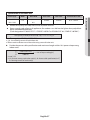
Maintaining your air conditioner
Internal protections via the unit control system
This internal protection operates if an internal fault occurs in the air conditioner.
Type
Against cold air
Defrost cycle
Protect compressor
Description
The internal fan will be off to prevent cold air when the heat pump is heating.
The internal fan will be off to defrost ice when the heat pump is heating.
Vertical air flow blade will be closed during defrost cycle and it will open again during
heating operation after defrost cycle.
The air conditioner does not start operating immediately to help protect the compressor
of the outdoor unit after it has been started.
• If the heat pump is operating in Heat mode, defrost cycle is actuated to help remove frost from an outdoor unit that
may have deposited at low temperatures.
The internal fan is switched off automatically and restarted only after the defrost cycle is completed.
English-10
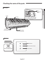
Checking the name of the parts
Main parts
Air filter
Air flow blade
(up and down)
Air intake
Air flow blade
(left and right)
Display
Power indicator
Timer/Auto clean indicator
Power button/
Remote controller receiver
Turbo indicator
English-11
01 PREPARATION
Room
temperature
sensor
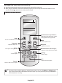
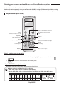
Using the remote controller
ffPoint the remote controller towards the remote controller receiver of the indoor unit.
ffWhen you press the button on the remote controller correctly, you will hear beep sound from the indoor unit and a
transmit indicator( ) appears on the remote controller display.
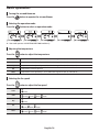
Remote controller buttons
Air flow direction (Up and down)
Adusts the air flow direction up and down
(Not applicable to Duct type models).
Power
Turns the air conditioner on or off.
Mode
Selects operation mode.
Temperature
Fan speed
Adjusts the temperature.
Adjusts the fan speed.
Options
Air flow direction (Left and right)
Selects options during operation.
Adjusts the air flow direction left and right.
Timer
Settings
Sets timer option.
Selects settings.
SET
Selects or cancels an option.
Direction
Moves to select and set an option.
NOTE
• In case you wish to cancel the options or settings that you have just set, press the Options or Settings button
again, then the most recently selected item will blink and you may simply cancel it by pressing the SET button
while selected item is blinking.
English-12
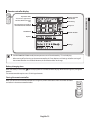
Remote controller display
Remote controller
transmission
Low battery
Set temperature or on/off set
time with the timer function
Fan speed
On/Off timer
Air flow direction
Options
Settings
NOTE
• For MR-EH00U/MR-EC00U model, the temperature unit will be indicated by "°F" on the display.
• When turning off and turning on the remote controller, the Timer, Options and Settings set before turning off
the remote controller are cancelled. However, the fan direction does not change.
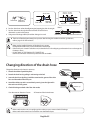
Battery changing time
When the battery is exhausted, ( ) will be displayed on the remote controller display. When the icon appears, change the
batteries.
The remote controller requires two 1.5V AAA type batteries.
Storing the remote controller
When you do not use the remote controller for a long time, remove the batteries from the remote controller
and store it in the remote controller holder.
English-13
01 PREPARATION
Operation mode
*Heat mode is applicable to
MR-EH00/MR-EH00U model
only.
Using the remote controller
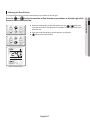
Inserting the batteries
1. Open the battery cover of the remote controller.
-- Press the (
) part gently and lift it up in the arrow direction.
2. Insert the batteries.
-- Check and match the (+)and (-) signs accordingly.
3. Close the battery cover.
-- Match the cover and bottom part of the remote controller and press it until you hear click
sound.
CAUTION
NOTE
• Make sure that water is not allowed to enter the remote controller.
• There is a possibility that the air conditioner will not operate by remote controller near strong light such as a
fluorescent lamp or neon sign. In this case, use the remote controller in front of the remote controller receiver of
the indoor unit.
• If other electrical products are operated by the remote controller, call your nearest service center.
• Filter reset : When the filter reset indicator is turned on the indoor unit display, clean the filter and press the
Settings <, > or Settings (Filter Reset) blinking SET button.
• Beep off : To silence the beep sound, press the Settings <, > or Settings (Beep) blinking SET button. If
you press the Settings <, > or Settings (Beep) blinking SET button again, the beep sound
will ring again.
Correct disposal of batteries in this product
(Applicable in countries with separate collection systems)
This marking on the battery, manual or packaging indicates that the batteries in this product should not be disposed
of with other household waste at the end of their working life. Where marked, the chemical symbols Hg, Cd or Pb
indicate that the battery contains mercury, cadmium or lead above the reference levels in EC Directive 2006/66. If
batteries are not properly disposed of, these substances can cause harm to human health or the environment.
To protect natural resources and to promote material reuse, please separate batteries from other types of waste and
recycle them through your local, free battery return system.
English-14
Basic operation
Basic operation is an operation mode that can be selected by pressing the Mode button.
Auto
Cool
Cool mode is frequently used and you can freely control the temperature, fan speed, and air flow direction in Cool mode.
ffWhen you select the Heat mode while the Cool mode is on, the Cool mode is cancelled.
Dry
The air conditioner in Dry mode acts like a dehumidifier by removing moisture from the indoor air. The Dry mode will provide
you with fresh air even on a rainy day.
Fan
Fan mode provides you with a breeze just like a fan to make fresh environment for you.
Heat (MR-EH00/MR-EH00U)
In Heat mode, you can warm your room even in the fall and winter.
ffThe fan may not commence immediately to avoid generating a cold breeze.
ffDuring the Heat mode, defrost operation may be performed to remove the frost formed on the outdoor unit. (When the
frost is removed by the defrost operation in Heat mode, steam is generated from the outdoor unit.)
ffIf you stop operating the air conditioner after heating operation, the fan will operate for some time to cool the indoor
unit.
ffWhen you select the Cool mode while the Heat mode is on, the Heat mode is cancelled.
NOTE
• When the outdoor temperature is low and humidity is high during the heat mode, the outdoor unit's heating
capacity may decrease due to the frost formed on the outdoor heat exchanger. The defrost operation removes
the frost formed on the heat exchanger of the outdoor unit for 5 ~ 12 minutes. During the defrost operation, the
indoor unit does not generate breeze in order to prevent cold breeze blowing out.
❋❋ The interval between the defrost operation can decrease depending on the amount of the frost formed on the
outdoor unit.
❋❋ The interval between defrost operation can also decrease by humidity level with rain or snow.
English-15
02 BASIC OPERATION
In Auto mode, the air conditioner will automatically adjust the temperature and fan speed to maintain your fresh
environment.
ffWhen the indoor temperature is too high, the powerful cool breeze is generated and when the indoor room becomes
cool enough, the soft breeze is generated.
Basic operation
Turning the air conditioner on
Press the
button to operate the air conditioner.
Selecting the operation mode
Press the
button to select an operation mode.
❋❋ Heat mode operates with MR-EH00/MR-EH00U model only.
Adjusting the temperature
Press the
button to adjust the temperature.
Auto
Temperature can be adjusted by 1 °C(1 °F) within the range of 18 °C(65 °F)~30 °C(86 °F).
Cool
Temperature can be adjusted by 1 °C(1 °F) within the range of 18 °C(65 °F)~30 °C(86 °F).
Dry
Temperature can be adjusted by 1 °C(1 °F) within the range of 18 °C(65 °F)~30 °C(86 °F).
Fan
Temperature cannot be adjusted.
Heat
Temperature can be adjusted by 1 °C(1 °F) within the range of 16 °C(61 °F) ~30 °C(86 °F).
Selecting the fan speed
Press the
Auto
Cool
Dry
Fan
Heat
button to adjust the fan speed.
(Auto)
(Auto),
(Low),
(Med),
(Low),
(Med),
(High)
(Auto),
(Low),
(Med),
(High)
(Auto)
(High)
English-16
Selecting air flow direction
This function allows you to shift the air flow direction up and down or left and right.
ffWhen the blade reaches the desired position, press the
or
button one
more time to set the air flow direction. The up/down and left/right tilting of the
blade will stop.
❋❋ Duct type model cannot adjust air flow direction up and down.
❋❋
button not available on RAC.
Remote controller display
English-17
02 BASIC OPERATION
Press the
or
button to move the air flow direction up and down or left and right while
the air conditioner is turned on.
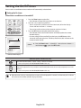
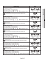
Setting the On/Off timer
You can set the air conditioner to be turned on or off automatically at desired time.
Setting the On timer
When the air conditioner is turned off.
1. Press the Timer button to select (On).
-- (On) indicator will keep blinking and you can set the time.
2. Press the < or > button to set the time.
-- You can set the time in half hour unit from 30 minutes (0.5 on the display) ~
3 hours and hour unit from 3 ~ 24 hours.
-- Time can be set from minimum 30 minutes to maximum 24 hours.
3. Press the SET button to complete the On timer setting.
-- (On) indicator and the set time of the timer will be displayed on the remote
controller display.
-- On timer setting will be cancelled if you don't press the SET button within
10 seconds after setting the time. Therefore, check for the (On) indicator on the
remote controller display.
Cancel
ffPress the Timer button select (On) press the < or > button
set the timer to
press the SET button.
Remote controller display
Additional options available in On timer
Select the mode from (Auto) (Cool) (Dry) (Fan) and (Heat).
❇❇ Heat mode operates with MR-EH00/MR-EH00U model only.
You can adjust the temperature after timer setting is completed.
Temperature adjustment is only available in Auto/Cool/Dry/Heat mode. In Fan mode, temperature cannot be
adjusted.
❇❇ Heat mode operates with MR-EH00/MR-EH00U model only.
NOTE
• When On timer setting is completed, the set status will be displayed for 3 seconds, and then only (On) indicator
will remain on the remote controller display thereafter.
English-18
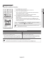
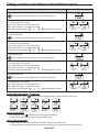
Setting the Off timer
When the air conditioner is turned on
ffPress the Timer button select (Off) press the < or > button
set the timer to
press the SET button.
Cancel
NOTE
• Only the latest setting timer will be applied between the Off Timer and
good’ sleep off timer functions.
Remote controller display
Combining On timer and Off timer
When the air conditioner is turned off
When the air conditioner is turned on
When set time on On timer is shorter than Off timer
e.g. On timer: 3 hours, Off timer: 5 hours
• The air conditioner will be turned on after 3 hours from the
moment you have set the timer and the air conditioner will
remain on for 2 hours and then be turned off automatically.
NOTE
When set time on On timer is longer than Off timer
e.g. On timer: 3 hours, Off timer: 1 hour
• The air conditioner will be turned off after 1 hour from the
moment you have set the timer and will be turned on after
2 hours from the moment it was turned off.
• Set time for the On timer and the Off timer should be different from each other.
• When the On timer or the Off timer is set, setting can be cancelled by pressing the Power button.
English-19
03 TIMER
1. Press the Timer button to select (Off).
-- (Off) indicator will keep blinking and you can set the time.
2. Press the < or > button to set the time.
-- You can set the time in half hour unit from 30 minutes (0.5 on the display) ~
3 hours and hour unit from 3 ~ 24 hours.
-- Time can be set from minimum 30 minutes to maximum 24 hours.
3. Press the SET button to complete the Off timer setting.
-- (Off) indicator and the set time of the timer will be displayed on the remote
controller display.
-- Off timer setting will be cancelled if you don't press the SET button within
10 seconds after setting the time. Therefore, check for the (Off) indicator on the
remote controller display.
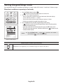
Setting the good’sleep mode
For a comfortable sleep, the air conditioner will operate in 3 stages in order of ‘Fall asleep Sound sleep Wake up’ stages.
When the air conditioner is operating in Cool mode;
1. Press the Timer button to select ( ).
-- (
) indicator will keep blinking and you can set the time.
2. Press the < or > button to set the time.
-- You can set the time in half hour unit from 30 minutes (0.5 on the display) ~
3 hours and hour unit from 3 ~ 12 hours.
-- Time can be set from minimum 30 minutes to maximum 12 hours.
-- Default time setting for the good'sleep mode is 8 hours.
3. Press the SET button to complete the good'sleep mode setting.
-- (
) indicator and the set time of the good'sleep mode will be displayed on
the remote controller display.
-- good'sleep mode will be cancelled if you don't press the SET button within
10 seconds after setting the time. Therefore, check for the (
) indicator on the
remote controller display.
Cancel
ffPress the Timer button select ( ) press the < or > button
set the timer to
press the SET button.
Remote controller display
Additional options available in good'sleep mode
Temperature can be adjusted by 1 °C(1 °F) within the range of 18 °C(65 °F)~30 °C(86 °F).
English-20
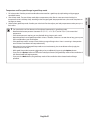
Temperature and Fan speed change in good’sleep mode
NOTE
• Fan speed and the air flow direction will be adjusted automatically in good'sleep mode.
• Recommended set temperature is between 25 °C(77 °F) ~ 27 °C (81 °F) and 26 °C(79 °F) is the most ideal
temperature.
• If the set temperature is too low, you may feel cold during sleep or catch a cold.
• Optimal operation hour of good'sleep mode is 8 hours. Therefore, if the time is set too short or long, you may not
feel as comfortable as you would expect.
• If the good'sleep mode is set over 5 hours, Wake up stage will begin when 1 hour is remaining in the operation
time and the air conditioner will stop automatically.
• When the On timer and the good'sleep mode are set simultaneously, the air conditioner will only apply the
function that was set later.
• While good'sleep mode is operating, mode can be set additionally by pressing the Options button.
• If you press the Options button and select the Turbo/Quiet function, the good'sleep mode will be cancelled and
the selected mode will begin operation.
• If you press the Mode button, the good'sleep mode will be cancelled and the selected mode will begin
operation.
English-21
03 TIMER
1. Fall asleep mode : Provides you with comfortable environment for a good sleep by rapid cooling and hypnagogue
expedition breeze.
2. Sound sleep mode : The sound sleep mode adjusts temperature and air flow in waves to maintain healthy skin
temperature while it aids deep sleep. According to the change of good’ sleep operation hours, the sound sleep hour can
be longer or shorter.
3. Wake up from good’sleep mode : Provides you with the air flow that adjusts your body temperature to wake you up in a
fresh status.
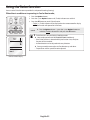
Using the Turbo function
You can set the Turbo function to provide fast and powerful cooling (heating).
When the air conditioner is operating in Cool or Heat mode;
1. Press the Options button.
2. Press the <, > or Options button until (Turbo) indicator starts to blink.
3. Press the SET button to set the Turbo function.
-- (Turbo) (Turbo) indicator will be displayed on the remote controller display
and Turbo function will operate for 30 minutes.
Cancel
NOTE
ffPress the Options button press the <, > or Options button to
make the (Turbo) indicator blink and press the SET button.
• Turbo function is only available in Cool/Heat mode.
❋❋ Heat mode operates with MR-EH00/MR-EH00U model only.
• If the Turbo function is selected while Quiet function is on, the Quiet
function will be cancelled.
• Air flow direction can be adjusted with every direction.
❋❋ Duct type model cannot adjust air flow direction up and down.
• Temperature and fan speed cannot be adjusted.
Remote controller display
English-22
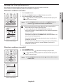
Using the Purity function
Purity function will remove harmful materials in the air to provide you clean and healthy environment.
You can select this function additionally while the air conditioner is in operation.
When the air conditioner is turned on
ffPress the Options button press the <, > or Options button to
make the ( ) indicator blink and press the SET button.
Cancel
NOTE
Remote controller display
• You may select the purity function additionally during Auto/Cool/Dry/
Heat mode and you can adjust the temperature.
❋❋ Heat mode operates with MR-EH00/MR-EH00U model only.
• If the purity function is selected additionally in fan mode, the temperature
cannot be adjusted.
• When the air conditioner and the purity function are turned on
simultaneously and you press the Power button, both air conditioner and
purity function will stop operation.
• You can still use the purity function when the On timer is set with the air
conditioner is turned off.
• There will not be much difference on energy consumption and operating
noise when the purity function is selected additionally while the air
conditioner is turned on.
When the air conditioner is turned off
1. Press the Options button.
2. Press the SET button when ( ) indicator blinks to begin purity function.
-- ( ) ( ) indicator will be displayed on the remote controller display and
Virus doctor function will begin.
Cancel
ffPress the Options button to make the (
the SET button.
Remote controller display
English-23
) indicator blink and press
04 OPTIONS
1. Press the Options button.
2. Press the <, > or Options button until ( ) indicator starts to blink.
3. Press the SET button to set the Purity function.
-- ( ) ( ) indicator will be displayed on the remote controller display and
Virus Doctor function will begin.
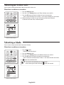
Selecting an indoor unit
You can select and operate individual indoor units out of 4 indoor units.
When the air conditioner is turned on
1. Press the Settings button.
2. Press the <, > or Settings button until (Zone) indicator starts to blink.
3. Press the SET button to select the indoor unit you want to operate.
-- You can select individual units in order (1~4) or select all indoor units at one time.
❋❋ Before Selectiing an Indoor unit ,you need setting indoor zone .Reference
installation manual 02 series installation option.
Remote controller display
Selecting a blade
You can select and operate individual blades out of 4 blades.
When the air conditioner is turned on
1. Press the button.
-- Blade 1234 will be displayed.
2. Press the Settings button.
3. Press the <, > or Settings button until (Blade) indicator starts to blink.
4. Press the SET button to select the blade you want to operate.
-- You can select the individual blades in order (1~4) or select all blades at one time.
❋❋
NOTE
button not available on RAC.
• To cancel the selected blade, press the
• When selecting the blade individually,
Remote controller display
English-24
button.
button will not work.
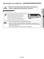
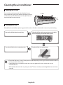
Cleaning the air conditioner
•Make sure to turn off the power of the indoor unit and cut-off
the power supply before cleaning the air conditioner.
Cleaning the indoor unit
Wipe the surface of the unit with a slightly damp micro fiber cloth when needed.
• C
ontact the service center when you clean the indoor unit
heat exchanger because it needs to be disassembled.
• Since the panel of the indoor unit is easily scratched, you
should use a micro fiber cloth to clean the panel.
When you use the micro fiber cloth, slightly dampen the cloth
and remove any debris on the cloth to avoid scratches.
•Do not clean the display using alkaline detergent.
CAUTION •Do not use sulfuric acid, hydrochloric acid, organic solvents (such as
thinner, kerosene and acetone etc.) to clean the surface of the product
or put any stickers on it.
They may damage the surface of the air conditioner.
English-25
05 SETTINGS
CAUTION
Cleaning the air conditioner
Removing the Air filter
There is a hole on the bottom right side of the filter. Put your
finger in that hole to get a grip on the filter and slightly push it up
to release the hooks from the bottom side. Then, pull it down to
remove the filter from the main body.
Air filter
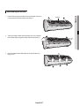
Cleaning the air filter
Washable foam based air filter captures large particles from the air. The filter is cleaned with a vacuum or by hand washing.
Remove the Air filter from the main body.
Clean the Air filter with a vacuum cleaner or soft brush.
If dust is too heavy, rinse it with running water.
Insert the Air filter back in its original position.
Dry the Air filter in a ventilated area.
• C
lean the Air filter every 2 weeks. Cleaning term may differ depending on the usage and environmental conditions.
In dusty area, clean it once a week.
• If the Air filter dries in a confined (or humid) area, odors may generate. If it occurs, re-clean and dry it in a
well-ventilated area.
• When the filter clean reminder is on, please press the 2nd F button and then press the Single User button on remote
controller.
English-26
Reassembling the Air filter
2. There’s one hook in both side of the filter, press the surface of
the Air filter softly and get the hooks into the main body.
3. Press the bottom of the filter lightly to securely fix the main
body.
English-27
Air filter
06 OTHERS
1. Put the filter on the main body and insert the hooks which are
in the top of the Air filter into the main body.
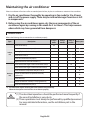
Maintaining the air conditioner
If the air conditioner will not be used for an extended period of time, dry the air conditioner to maintain it in best condition.
1.Dry the air conditioner thoroughly by operating in Fan mode for 3 to 4 hours
and cut-off the power supply. There may be internal damage if moisture is left
in components.
2.Before using the air conditioner again, dry the inner components of the air
conditioner again by running in Fan mode for 3 to 4 hours. This helps remove
odors which may have generated from dampness.
Periodical checks
Refer to the following chart to maintain the air conditioner properly.
Type
Every 2
weeks
Description
Clean the air filter (1)
Indoor
unit
Every 3
months
Every 4
months
Clean the condensate drain pan (2)
Thoroughly clean the heat exchanger (2)
Clean the cross fan (2)
Clean the condensate drain pipe (2)
Replace the remote controller batteries (1)
Clean the heat exchanger on the outside of the unit (2)
Outdoor
unit
Once a year
Clean the heat exchanger on the inside of the unit (2)
Clean the electric components with jets of air (2)
Verify that all the electric components are firmly
tightened (2)
Clean the fan (2)
Verify that all the fan assembly is firmly tightened (2)
Clean the condensate drain pan (2)
: This check mark requires checking the indoor/outdoor unit periodically.
Follow the description to maintain the air conditioner properly.
(1) The described operations should be performed more frequently if
the area of installation is very dusty.
CAUTION
(2) These operations must always be performed by qualified personnel.
For more detailed information, see the installation part in the
manual.
English-28
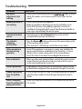
Troubleshooting
Refer to the following chart if the air conditioner operates abnormally. This may save
time and unnecessary expenses.
SOLUTION
The air conditioner
does not work at all.
• Check power status and then operate the air conditioner again.
• Plug in or switch on the circuit breaker and then operate the air
conditioner again.
• Ensure Isolator is switch on.
• Check if you have set the Off Timer. Operate the air conditioner
again by pressing the Power button.
The temperature
adjustment is not
working.
• Check if you have selected Fan/Fast mode. In these modes, desired
temperature is set to auto and you cannot adjust the temperature.
Cool/Warm air does
not come out of the
air conditioner.
• Check if the set temperature is higher(during Cool mode)/
lower(during Heat mode) than the current temperature. Press the
Temp + or - button on the remote controller to change the set
temperature.
• Check if the Air filter is blocked by dirt. If there is a lot of dust on
the Air filter, cooling(heating) performance may decrease. Clean
them frequently.
• Check if the outdoor unit is covered or installed near the obstacle.
Take the cover off and take the obstacle away.
• Check if the air conditioner is operating in defrost mode. When the
ice formed in winter or the outdoor temperature is too low, the
air conditioner operates in defrost mode automatically. In defrost
mode, indoor fan stops and warm air does not come out.
• If the doors or windows are open, it may cause bad cooling
(heating) performance.
Close the doors and windows.
• Check if the air conditioner has just been turned on after stopping
cooling or heating operation. In this case, just a fan will run to
protect the outdoor unit compressor.
• Check if the pipe length is too long. When the pipe length exceeds
maximum allowable pipe length, cooling (heating) performance
may decrease.
Air flow adjustment
is not working.
• Check if you have selected
mode. In cool mode, you
mode is
cannot adjust the air flow direction. (If the
operating in Heat mode, you can adjust the air flow direction.)
English-29
06 OTHERS
PROBLEM
Troubleshooting
PROBLEM
SOLUTION
Fan speed
adjustment is not
working.
• Check if you have selected Auto/Dry/
mode. In these
mode, fan speed is set to Auto and you cannot adjust the fan
speed.
Remote controller is
not working.
• Check if your batteries are depleted.
• Make sure nothing is blocking your remote controller sensor.
• Check that there are strong lighting apparatus near the air
conditioner. Strong light which comes from fluorescent bulbs or
neon signs may interrupt the electric waves.
Timer function does
not set.
• Check if you press the Set/Cancel button on the remote
controller after you have set the time.
The indicator
is blinking
continuously.
• Press the Power button or disconnect the power plug/switch
off the auxiliary power switch.
If the indicator is still blinking, contact the service center.
Odors permeate in
the room during
operation.
• Check if the appliance is running in a smoky area. Ventilate the
room or operate the air conditioner in Fan mode for 1~2 hours.
(We do not use smelly components in the air conditioner.)
• Check the Drains have been cleared Regular Maintenance.
Error is indicated.
• When an indoor unit indicator blinks, contact the nearest service
center. Please ensure the error code is passed onto the service
center when booking the service call.
Noise is generated.
• Depending on the status of the air conditioner usage, noise can
be heard when refrigerant flow movement changes. It is normal.
Smoke is generated
from the outdoor
unit.
• If may not be a fire but it can be a steam generated by the defrost
operation from outdoor heat exchanger during Heat mode in
winter.
Water is dropping
• Water may be generated because of the temperature difference.
from the outdoor unit
It is normal.
piping connection.
English-30
Appendix
Model specification (Dimension and weight)
Dimension and weight
Indoor unit
Model
Net dimension (WxDxH)
(mm)
Net weight
(kg)
AM015JNVDKH
750*250*242
8.1
AM022JNVDKH
750*250*242
8.1
AM028JNVDKH
750*250*242
8.2
AM036JNVDKH
826*275*260
9.8
AM045JNVDKH
826*275*260
9.8
AM056JNVDKH
1063*317*294
14.6
AM071JNVDKH
1063*317*294
14.6
AM082JNVDKH
1063*317*294
14.6
AM015JNADKH
750*250*242
7.9
AM022JNADKH
750*250*242
7.9
AM028JNADKH
750*250*242
8.0
AM036JNADKH
826*275*260
9.5
AM045JNADKH
826*275*260
9.5
AM056JNADKH
1063*317*294
14.3
AM071JNADKH
1063*317*294
14.3
AM082JNADKH
1063*317*294
14.3
English-31
06 OTHERS
Type
Installation parts
Fixing the installation plate
You can select the direction of the drain hose depending on where you want to install the indoor unit. Therefore before fixing
the installation plate to a wall or a window frame, you must determine the position of the 65 mm hole through which the cable,
pipe and hose pass to connect the indoor unit to the outdoor unit.
When facing the wall, the pipe and cable can be connected from the:
Direction of pipe
• Right (A)
• Left (B)
• Underside_right (C)
• Rear_right or left (D)
B
A
D
D
C
1. Disassemble the cover panel as described in installation manual.
2. Remove the Hanger plate from the indoor unit.
(1) Unscrew 2 screws that fixes the Hanger plate to the indoor unit.
(2) Push the hooks (on the bottom part of the indoor unit) up to release the installation plate from the hooks that holds it.
(3) Pull the installation plate to release it completely from the indoor unit.
Screw
3. Determine the position of the pipe and drain hose hole as seen in the picture and drill the hole with an inner diameter
of 65 mm so that it slants slightly downwards.
B
C
C
D
A
D
D
B
Pipe hole (Ø65 mm)
A
Pipe hole (Ø65 mm)
A
Pipe hole (Ø65 mm)
B
C
(Unit : mm)
Model
A
B
C
D
015/022/028
36
60
65
36
036/045
36
120
81
36
056/071/082
33
110
110
33
• M
ake sure to drill only one hole after choosing the
direction of the pipe.
4. Fix the indoor unit.
If you fix the indoor unit on a wall
(1) Fix the installation plate to the wall giving attention to the weight of the indoor unit.
• If you mount the plate to a concrete wall using plastic anchors, make sure that gaps
between the wall and the plate, created by projected anchor, is less than 20 mm.
Plastic
Anchor
If you fix the indoor unit on a window frame
(1) Determine the positions of the wooden uprights to be attached to the window frame.
(2) Attach the wooden uprights to the window frame giving attention to the weight of the indoor unit.
(3) Attach the installation plate to the wooden upright using tapping screws.
If you fix the indoor unit on a gypsum board
(1) Use stud finder to find out locations of the studs.
(2) Fix the plate hanger on two studs.
English-32
<20 mm
Wall
• S earch for other spots if there are less than two studs, or the distance between the studs are different from the
plate hanger.
• Fix the installation plate without inclining to one side.
Assembling the hanger screw
Use 2 screws to fix the indoor unit with hanger plate as shown
in the picture.
Screw
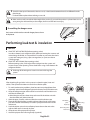
Performing leak test & insulation
Leak test
LEAK TEST WITH NITROGEN (before opening valves)
In order to detect basic refrigerant leaks, before recreating the vacuum and
recirculating the R410A, it’s responsible of installer to pressurize the whole
system with nitrogen (using a pressure regulator) at a pressure above
4.1MPa (gauge).
C
D
LEAK TEST WITH R410A (after opening valves)
Before opening valves, discharge all the nitrogen into the system and
create vacuum. After opening valves check leaks using a leak detector for
refrigerant R410A.
• Discharge all the nitrogen to create a vacuum and charge the
system.
Insulation
After checking for gas leaks in the system, insulate the pipe, hose and
cables. Then place the indoor unit on the installation plate.
1. To avoid condensation problems, place heat-resistant polyethylene foam
separately around each refrigerant pipe in the lower part of the indoor unit.
2. Wrap the refrigerant pipe and the drain hose in the rear of the indoor unit
with the absorbent pad.
Wind the pipe and hose three times to the end of the indoor unit with
the absorbent pad. (20mm interval)
3. Wind the pipe, assembly cable and drain hose with insulation tape.
4. Place the bundle (the pipe, assembly cable and drain hose) in the lower
part of the indoor unit carefully so it doesn’t project from the rear of the
indoor unit.
5. Hook the indoor unit to the installation plate and move the unit to the
right and left until it is securely in place.
6. Wrap the rest of the pipe with vinyl tape.
7. Attach the pipe to the wall using clamps (optional).
English-33
Insulation
Pipes
Installation
plate
Vinyl tape
Connecting wires
Drain hose
Connecting
pipes
07 INSTALLATION
• M
ake sure that a wall can withstand the weight of the product. If you install the product in a place where it is not
strong enough to withstand the product weight, the unit could fall and cause injury.
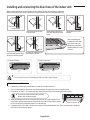
Installing and connecting the drain hose of the indoor unit
When installing the drain hose for the indoor unit, check if condensation draining is adequate.
When passing the drain hose through the 65 mm hole drilled in the wall, check the followings:
Wall
Indoor unit
Drain hose
The drain hose must NOT
slant upwards.
5cm
less
The end of the drain hose
must NOT be placed under
water.
The drain hose must not
be bent.
After completing the
installation of the drain
hose, pour water into
the drain pan to check
whether the hose is well
drained.
Ditch
Keep a clearance of at least
Do not place the end of the
5 cm between the end of the drain hose in a hollow.
drain hose and the ground.
2) Incorrect connection
1) Correct connection
Drain hose
Pipe
Drain hose
Pipe
• Don’t tie drain hose to the assembly pipe which may lead to water leakage.
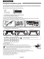
Drain hose installation
1. If necessary, connect the 2 meter extension drain hose to the drain hose.
2. If you use the extension drain hose, insulate the inside of the extension drain hose with a shield.
3. Fit the drain hose into 1 of 2 drain hose holes, then fix the end of the drain hose tightly with a clamp.
• If you do not use the other drain hose hole,
block it with a rubber stopper.
4. When extending the Drain Hose, hold the end of Drain Hose and Extended Hose,
rotate and insert the drain hose into Extended hose for 40~45 mm. Make sure the
two hoses are firmly connected, there is no water leakage.
Drain hose hole
5. Connect the Drain Hose after using Foam Insulation to wrap the Extended Hose. Then, Use vinyl tape to wrap the
each side of connection by 20 mm .
English-34
20 mm 20 mm
or more or more
40~45 mm
Drain hose
Extension
drain hose
Vinyl Tape
Shield
6. Pass the drain hose under the refrigerant pipe, keeping the drain hose tight.
7. Pass the drain hose through the hole in the wall. Check if it slants
downwards as seen in the picture.
Drain hose
8. Using natural drainage method, check the drainage is normal.
Foam Insulation
Extension drain hose
• T he hose will be fixed permanently into position after finishing the installation and the gas leak test;
refer to page 22 for further details.
• M
ake sure the installed direction of the drain hose is correct.
Inadequate installation may cause condensate water leakage.
• If the drain hose is routed inside the room, insulate the hose so that dripping condensation does not damage the
furniture or floors.
• DO NOT WALL UP THE DRAIN HOSE CONNECTION !
Drain hose connection must be easy accessible and serviceable.
Changing direction of the drain hose
Change the direction only when it is necessary.
Screw hole
Screw
1. Detach the rubber cap with the pliers.
2. Detach the drain hose by pulling it and turning to the left.
3. Insert the drain hose by fixing it with the screw into the groove of the drain
hose and the outlet of the drain pan.
4. Attach the rubber cap with a screwdriver by turning it to the right until it
fixes to the end of the groove.
5. Check for leakage on both side of the drain outlet.
Pour the water in direction of arrow.
Direction of the drained water
• M
ake sure the indoor unit is in upright position when you pour water to check for leakage.
Make sure that the water does not overflow onto the electrical part.
English-35
Drain hose
Drain pan outlet
Rubber cap
07 INSTALLATION
Drain hose Extension
drain hose
Wiring work
Power and communication cable connection
1. Before wiring work, you must turn off all power source.
2. Indoor unit power should be supplied through the breaker( ELCB or MCCB+ELB ) separated by the outdoor power.
ELCB : Earth Leakage Circuit Breaker
MCCB : Molded Case Circuit Breaker
ELB : Earth Leakage Breaker
3. The power cable should be used only copper wires.
4. Connect the power cable{1(L), 2(N)} among the units within maximum length and communication
cable(F1, F2) each.
5. Connect F3, F4(for communication) when installing the wired remote control.
Outdoor Unit
Wired Remote
Control
220-240V~
or
ELCB
Indoor Unit 1
Indoor Unit 2
V2
L
V1
Indoor Unit 3
h ELCB : Essential Installation
WARNING :
Power off before connecting any wires;
Indoor PBA will be damaged while V1,V2,F3,F4 short each
other.
EEV kit
N
MCCB+
ELB
N
Indoor Unit 4
Indoor Unit 5
L
N
L
N
L
Indoor Unit 6
h Ceiling, wall-mounted indoor unit.
Selecting compressed ring terminal
Silver solder
B
D
d1
E
F
L
d2
t
Norminal Norminal
Standard
Standard
Standard
dimensions dimensions Standard
Allowance
Allowance
Allowance
Allowance
dimension
dimension
Min. Min. Max. dimension
Min.
for cable for screw dimension
(mm)
(mm)
(mm)
(mm)
(mm)
(mm)
(mm)
(mm)
(mm2)
(mm)
+0.3
+0.2
4
6.6
1.5
±0.2
3.4
1.7
±0.2
4.1
6
16
4.3
0.7
4
8
-0.2
0
+0.3
+0.2
4
6.6
2.5
±0.2
4.2
2.3
±0.2
6
6 17.5
4.3
0.8
4
8.5
-0.2
0
+0.3
+0.2
4
4
9.5
±0.2
5.6
3.4
±0.2
6
5
20
4.3
0.9
-0.2
0
English-36
Specification of electronic wire
MCCB
ELB or ELCB
Power cable
Earth cable
Communication cable
Max : 242V
Min : 198V
XA
X A, 30mmA
0.1 s
2.5mm2
2.5mm2
0.75~1.5mm2
Decide the capacity of ELCB(or MCCB+ELB) by below formula.
Power supply cords of parts of appliances for outdoor use shall not be lighter than polychloro-
prene sheathed flexible cord.
(Code designation IEC:60245 IEC 57 / CENELEC: H05RN-F or IEC:60245 IEC 66 / CENELEC: H07RN-F )
The capacity of ELCB(or MCCB+ELB) X [A] = 1.25 X 1.1 X ∑Ai
T X : The capacity of ELCB(or MCCB+ELB).
T ∑Ai : Sum of Rating currents of each indoor unit.
T Refer to each installation manual about the rating current of indoor unit.
Decide the power cable specification and maximum length within 10% power drop among
indoor units.
n
Coef×35.6×Lk×ik
k=1
1000×Ak
∑(
) < 10% of input voltage[V]
T coef: 1.55
T Lk: Distance among each indoor unit[m], Ak: Power cable specification[mm2]
ik: Running current of each unit[A]
English-37
07 INSTALLATION
Power supply
Setting an indoor unit address and installation option
Set the indoor unit address and installation option with remote controller option.
Set the each option separately since you cannot set the ADDRESS setting and indoor unit installation setting
option at the same time. You need to set twice when setting indoor unit address and installation option.
The procedure of option setting
Air flow direction (Up and down)
Adusts the air flow direction up and down
(Not applicable to Duct type models).
Power
Turns the air conditioner on or off.
Mode
Selects operation mode.
Temperature
Adjusts the temperature.
Fan speed
Adjusts the fan speed.
Options
Selects options during operation.
Air flow direction (Left and right)
Adjusts the air flow direction left and right.
Timer
Sets timer option.
Settings
Selects settings.
SET
Selects or cancels an option.
Direction
Moves to select and set an option.
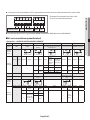
Step 1. Entering mode to set option
1. Remove batteries from the remote controller.
2. Insert batteries and enter the option setting mode while pressing High Temp button and Low Temp button.
Auto
3.
Check if you have entered the option setting status.
On
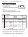
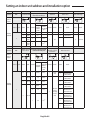
Step 2. The procedure of option setting
After entering the option setting status, select the option as listed below.
• Option setting is available from SEG1 to SEG 24
• SEG1, SEG7, SEG13, SEG19 are not set as page option.
• Set the SEG2~SEG6, SEG8~SEG12 as ON status and SEG14~18, SEG20~24 as OFF status.
SEG1 SEG2 SEG3 SEG4 SEG5 SEG6 SEG7 SEG8 SEG9 SEG10 SEG11 SEG12
0
X
X
X
X
X
1
X
X
X
X
X
SEG13 SEG14 SEG15 SEG16 SEG17 SEG18 SEG19 SEG20 SEG21 SEG22 SEG23 SEG24
2
X
X
X
X
X
3
X
X
X
English-38
X
X
On(SEG1~12)
Auto
On
Off(SEG13~24)
Auto
Off
Option setting
Status
Auto
On
On
SEG2
2. Setting Cool mode
SEG3
Cool
Press Mode button to be changed to Cool mode in the ON status.
3. Setting SEG4, SEG5 option
Press Low Fan button(∨) to enter SEG4 value.
Press High Fan button(∧) to enter SEG5 value.
Each time you press the button, … will be selected in rotation.
On
Cool
Cool
On
On
SEG4
SEG5
Dry
4. Setting Dry mode
On
Press Mode button to be changed to DRY mode in the ON status.
5. Setting SEG6, SEG8 option
Press Low Fan button(∨) to enter SEG6 value.
Press High Fan button(∧) to enter SEG8 value.
Each time you press the button, … will be selected in rotation.
Dry
Dry
On
On
SEG6
6. Setting Fan mode
SEG8
Fan
Press Mode button to be changed to FAN mode in the ON status.
7. Setting SEG9, SEG10 option
Press Low Fan button(∨) to enter SEG9 value.
Press High Fan button(∧) to enter SEG10 value.
Each time you press the button, … will be selected in rotation.
On
Fan
Fan
On
On
SEG9
8. Setting Heat mode
SEG10
Heat
On
Press Mode button to be changed to HEAT mode in the ON status.
9. Setting SEG11, SEG12 option
Press Low Fan button(∨) to enter SEG11 value.
Press High Fan button(∧) to enter SEG12 value.
Each time you press the button, … will be selected in rotation.
Heat
Heat
On
On
SEG11
SEG12
Auto
10. Setting Auto mode
Off
Press Mode button to be changed to AUTO mode in the OFF status.
11. Setting SEG14, SEG15 option
Press Low Fan button(∨) to enter SEG14 value.
Press High Fan button(∧) to enter SEG15 value.
Each time you press the button, … will be selected in rotation.
English-39
Auto
Auto
Off
Off
SEG14
SEG15
07 INSTALLATION
1. Setting SEG2, SEG3 option
Press Low Fan button(∨) to enter SEG2 value.
Press High Fan button(∧) to enter SEG3 value.
Each time you press the button, … will be selected in rotation.
Auto
Setting an indoor unit address and installation option
Option setting
Status
12. Setting Cool mode
Cool
Press Mode button to be change to Cool mode in the OFF status.
Off
13. Setting SEG16, SEG17 option
Press Low Fan button(∨) to enter SEG16 value.
Press High Fan button(∧) to enter SEG17 value.
Each time you press the button, … will be selected in rotation.
Cool
Cool
Off
Off
SEG16
SEG17
Dry
14. Setting Dry mode
Off
Press Mode button to be change to Dry mode in the OFF status.
15. Setting SEG18, SEG20 option
Press Low Fan button(∨) to enter SEG18 value.
Press High Fan button(∧) to enter SEG20 value.
Each time you press the button, … will be selected in rotation.
Dry
Dry
Off
Off
SEG18
16. Setting Fan mode
SEG20
Fan
Off
Press Mode button to be change to Fan mode in the OFF status.
17. Setting SEG21, SEG22 option
Press Low Fan button(∨) to enter SEG21 value.
Press High Fan button(∧) to enter SEG22 value.
Each time you press the button, … will be selected in rotation.
Fan
Fan
Off
Off
SEG21
18. Setting Heat mode
SEG22
Heat
Off
Press Mode button to be change to HEAT mode in the OFF status.
19. Setting SEG23, SEG24 mode
Press Low Fan button(∨) to enter SEG23 value.
Press High Fan button(∧) to enter SEG24 value.
Each time you press the button, … will be selected in rotation.
Heat
Heat
Off
Off
SEG23
SEG24
Step 3. Check the option you have set
After setting option, press
Auto
On
Dry
On
Auto
Off
button to check whether the option code you input is correct or not.
Cool
Dry
Cool
Off
Fan
On
Off
On
Heat
Fan
Off
On
Heat
Off
Step 4. Input option
Press operation button
with the direction of remote control for set.
For the correct option setting, you must input the option twice.
Step 5. Check operation
1. Reset the indoor unit by pressing the RESET button of indoor unit or outdoor unit.
2. Take the batteries out of the remote controller and insert them again and then press the operation button.
English-40
Setting an indoor unit address (MAIN/RMC)
Indoor Unit
1(L)
2(N)
1. Check whether power is supplied or not.
F2
F1
07 INSTALLATION
- When the indoor unit is not plugged in, there should be additional
power supply in the indoor unit.
2. The panel(display) should be connected to an indoor unit to receive option.
3. Before installing the indoor unit, assign an address to the indoor unit according to the air
conditioning system plan.
4. Assign an indoor unit address by wireless remote controller.
- The initial setting status of indoor unit ADDRESS(MAIN/RMC) is “0A0000-100000-200000-300000”.
Option No. : 0AXXXX-1XXXXX-2XXXXX-3XXXXX
Option
Explanation
SEG1
SEG2
PAGE
Remote
Controller
Display
Mode
SEG3
SEG4
100-digit of indoor
Setting Main address
unit address
Auto
Auto
On
On
SEG5
SEG6
10-digit of indoor
unit
The unit digit of
an indoor unit
Dry
Cool
Cool
On
On
On
Indication Details Indication Details Indication Details Indication Details Indication Details Indication Details
Indication
and Details
0
Option
SEG7
Explanation
PAGE
No Main
address
1
Main
address
setting
mode
A
SEG8
SEG9
0~9
100-digit
0~9
SEG10
Setting RMC address
Remote
Controller
Display
SEG12
Group channel(*16)
Group address
Heat
On
On
Indication Details
0
No RMC
address
1
RMC
address
setting
mode
1
__
A unit
digit
0~9
Heat
On
__
10-digit
SEG11
Fan
Indication Details
Indication
and Details
0
Indication Details Indication Details
RMC1
0~F
RMC2
0~F
• When “A”~”F” is entered to SEG5~6, the indoor unit MAIN ADDRESS is not changed.
• If you set the SEG 3 as 0, the indoor unit will maintain the previous MAIN ADDRESS even if you
input the option value of SEG5~6.
• If you set the SEG 9 as 0, the indoor unit will maintain previous RMC ADDRESS even if you input
the option value of SEG11~12.
• You cannot set SEG11 and SEG12 as F value at the same time.
English-41
Setting an indoor unit address and installation option
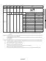
Setting an indoor unit installation option
(suitable for the condition of each installation location)
1. Check whether power is supplied or not.
Indoor Unit
- When the indoor unit is not plugged in, there should be additional
power supply in the indoor unit.
1(L)
2(N)
F2
F1
2. The panel(display) should be connected to an indoor unit to receive
option.
3. Set the installation option according to the installation condition of an air conditioner.
- The default setting of an indoor unit installation option is
“020010-100000- 200000-300000”.
- Individual control of a remote controller(SEG20) is the function that controls an
indoor unit individually when there is more than one indoor unit.
4. Set the indoor unit option by wireless remote controller.
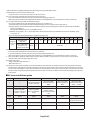
02 series installation option
SEG1
SEG2
SEG3
0
2
--
SEG7
SEG8
SEG9
SEG4
External room
temperature sensor
/ Minimizing fan
operation when
thermostat is off
SEG10
SEG5
SEG6
Central control
SEG11
SEG12
--
FAN RPM
compensation
1
Drain pump
Hot water heater
--
EEV Step when
heating stops
SEG13
SEG14
SEG16
SEG17
SEG18
2
External control
S-Plasma ion
Buzzer
Number of hours
using filter
SEG19
SEG20
SEG15
External control
output / External
heater On or Off
signal
SEG21
SEG22
SEG23
SEG24
3
Individual control of
a remote controller
Motion detect
sensor
--
Heating setting
compensation
EEV Step of stopped
/ Removing
unit during oil return/
condensated water in
defrost mode
heating mode
1WAY/2WAY/4WAY MODEL : Drain pump(SEG8) will be set to ‘USE + 3minute delay’ even if the drain
pump is set to 0.
1 WAY/2WAY/4WAY,DUCT MODEL : Number of hours using filter(SEG18) will be set to ‘1000hour’ even
if the SEG18 is set to exept for 2 or 6.
When setting the option other than above SEG values, the option will be set as “0”.
SEG5 central control option is basically set as 1 (Use), so you don’t need to set the central control
option additionally.
However, if the central control is not connected but it doesn’t indicate an error message, you need to
set the central control option as 0 (Disuse) to exclude the indoor unit from the central control.
English-42
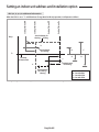
The output of hot water heater in SEG9 is generated from the hot coil part of the terminal board in duct models.
F1
F2
COM1
OUTDOOR
COMMUNICATION
V1
(+)
F3
V2
(-)
F4
COM2
1(L) 2(N) 1
L
Remote
DC 12 V Wire
Controller
07 INSTALLATION
* The output of hot coil terminal is AC 220 V / 230 V
(The same as Indoor Unit’s input Power)
2
N
AC
POWER
HOT
COIL
The external output of SEG15 is generated by MIM-B14 connection. (Refer to the manual of MIM-B14.)
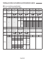
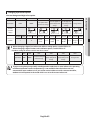
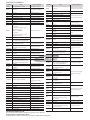
02 series installation option(Detailed)
Option No. : 02XXXX-1XXXXX-2XXXXX-3XXXXX
Option
Explanation
SEG1
PAGE
Remote
Controller
Display
SEG2
SEG3
MODE
Use of robot
cleaning
Auto
Auto
On
On
SEG4
Use of external room temperature
sensor / Minimizing fan operation when
thermostat is off
SEG5
SEG6
Use of central control
FAN RPM compensation
Dry
Cool
Cool
On
On
On
Details
Indication Details Indication
Details
Indication
and Details
0
2
Use of
Indication Details Indication External
room
temperature
sensor
0
Disuse
0
Disuse
1
Use
1
Option
Explanation
SEG7
PAGE
SEG8
SEG9
Use of drain pump
Use of hot water
heater
Dry
Remote
Controller
Display
Details
Details
Disuse
0
Disuse
Disuse
Use
Use (*1)
Use (*1)
1
Use
SEG10
SEG11
Details
0
Disuse
RPM
compensation
1
High ceiling
KIT
2
SEG12
Heat
On
Indication Details Indication
Disuse
0
Disuse
1
Use
1
Use (*2)
2
--
2
When an indoor
unit stops, drain
pump will operate
for 3min
Details
Indication
0
1
3
Indication
EEV Step when heating
stops
Fan
0
1
2
3
Indication
Disuse
On
On
Indication Details Indication
Indication
and Details
Use
Minimizing fan
operation when
thermostat is off
Use (*2)
English-43
Details
Default
value
Noise
decreasing
setting
Indication
Details
Setting an indoor unit address and installation option
Option
SEG13
Explanation
PAGE
Remote
Controller
Display
SEG14
SEG15
Setting the output of external control /
Use of external control
External heater On/Off signal
Auto
Auto
Off
Off
SEG16
SEG17
SEG18
S-Plasma ion
Buzzer control
Hours of filter usage
Dry
Cool
Cool
Off
Off
Off
Details
Setting the
External Indication Details Indication
Indication Details Indication Details Indication output of
Details
heater On/Off
external
signal
control
0
Disuse
0
Thermo on
0
Disuse
0
Use buzzer
Indication
ON/OFF
Operation
and Details
1
1
1
Disuse buzzer
control
on
OFF
2
2
2
Use (*3)
control
1
Use
Window
3
ON/OFF
3
Use (*3)
control
Option
SEG19
SEG20
SEG21
SEG22
SEG23
EEV Step of stopped
Individual control of a Heating setting compensation / Removing
Explanation
PAGE
unit during oil return/
Motion detect sensor
remote controller
condensated water in heating mode
defrost mode
Dry
Remote
Controller
Display
Off
Fan
Fan
Off
Off
Details
Removing
Indication Details Indication Details Indication Heating Setting Condensated Indication
Water in
Compensation
Heating
Mode
Details
Default
value
Indication
Details
0
Disuse
Turn out in 30min.
without motion
Turn out in 60min.
without motion
Turn out in 120min.
without motion
0 or 1
channel 1
0
Default (*4)
Disuse
2
channel 2
1
2 °C
Disuse
2
3
channel 3
2
5 °C
Disuse
3
3
Default (*4)
Use (*5)
4
4
2 °C
Use (*5)
Indication
and Details
3
0
Heat
Off
1
4
channel 4
5
5 °C
Use (*5)
Oil return
or Noise
decreasing
in defrost
mode
1
5
6
7
8
English-44
Turn out in 180min.
without motion
Turn out in 30min.
without motion or
*advanced function
Turn out in 60min.
without motion or
*advanced function
Turn out in 120min.
without motion or
*advanced function
Turn out in 180min.
without motion or
*advanced function
Indication
Details
2
1000 Hour
6
2000 Hour
SEG24
-
*
Indication
0
Wall Mounted
80
Stopped
With EEV
Unit's EEV
Other Indoor Units
step
except for wall Default
mounted with EEV
1
2
3
4
5
6
7
8
9
A
B
0
90
100
110
120
130
160
200
250
300
400
0
No Function
(*4) When the following 2 or 3 is used as external heater On/Off signal, the signal for monitoring external contact control will not be output.
2: Fan is turned on continually when the external heater is turned on,
3: Fan is turned off when the external heater is turned on with cooling only indoor unit
Cooling only indoor unit: To use this option,install the Mode Select switch(MCM-C200) on the outdoor unit and fix it as cool mode.
· If Fan is set to off for cooling only indoor unit by setting the SEG9=3 or SEG15=3, you need to use an external sensor or wired remote
controller sensor to detect indoor temperature exactly.
(*5) Default setting value
- 4Way Cassette, Mini 4Way Cassette: 5 °C
- Other indoor units: 2 °C
(*6) This function can be applied to 4 Way Cassette and Mini 4 Way Cassette only. If the air conditioner operates the heating mode immediately
after finishing the cooling mode, the condensated water in the drain pan becomes water vapor by the heat of the indoor unit heat exchanger.
Since the water vapor might be condensed on the indoor unit, which may fall into a living space, use this function to get rid of the water vapor
out of the indoor unit by operating the fan (for maximum 20 minutes) even when the indoor unit is turned off after cooling mode is turned to
heating mode .
05 series installation option
SEG1
SEG2
SEG3
0
5
Use of Auto Change Over for
HR only in Auto mode
SEG7
SEG8
SEG9
1
(When setting SEG3)
Standard for mode change
Cooling → Heating
(When setting SEG3)
Time required for mode
change
SEG13
SEG14
SEG15
SEG4
SEG5
SEG6
(When setting SEG3)
Standard heating temp.
Offset
SEG10
Compensation option for
Long pipe or height
difference between indoor
units
(When setting SEG3)
Standard cooling temp.
Offset
SEG11
(When setting SEG3)
Standard for mode change
Heating → Cooling
SEG12
-
-
SEG16
SEG17
SEG18
2
-
-
-
-
Control variables when using
hot water / external heater
SEG19
SEG20
SEG21
SEG22
SEG23
SEG24
3
-
-
-
-
-
English-45
07 INSTALLATION
Advanced function: Controlling cooling/heating current or power saving with motion detect.
(*1) Minimizing fan operation when thermostat is off
- Fan operates for 20 seconds at an interval of 5 minutes in heat mode.
(*2) 1: Fan is turned on continually when the hot water heater is turned on,
3: Fan is turned off when the hot water heater is turned on with cooling only indoor unit
Cooling only indoor unit: To use this option,install the Mode Select switch(MCM-C200) on the outdoor unit and fix it as cool mode.
(*3) It is only for wall-mounted indoor unit with EEV Integrated.
If any design condition meets either of the following below, please set SEG11 to “7”.
a) The total number of wall-mounted indoor units with EEV Integrated in one (modular) system is more than 20.
b) The total number of wall-mounted indoor units with EEV Integrated in one (modular) system is more than “the total of one(modular)
system’s capacity(kW) / 2”
(“the total of one(modular) system’s capacity(BTU/h) / 6800”).
ex) Outdoor capacity 28kW → 28 /2 = 14. The total number of wall-mounted indoor units with EEV Integrated in one (modular) system
is more than 14.
Please refer to the EEV step table below for the system (for heating) at stop.
Setting an indoor unit address and installation option
05 series installation option(Detailed)
Option No. : 05XXXX-1XXXXX-2XXXXX-3XXXXX
Option
Explanation
SEG1
SEG2
PAGE
SEG3
Use of Auto Change
Over for HR only in
Auto mode
MODE
Remote
Controller
Display
Auto
Auto
On
On
Indication Details Indication
Details
0
Explanation
SEG8
PAGE
(When setting SEG3)
Standard for mode
changing Cooling →
Heating mode
Dry
Remote
Controller
Display
On
Indication Details Indication
Indication
and Details
Details
Dry
Cool
Cool
On
On
On
Indication
Details
Indication
Details
0
0°C
0
0°C
0
1°C
Use Auto
Change
Over for
HR only
1
2
3
4
5
6
7
0.5°C
1°C
1.5°C
2°C
2.5°C
3°C
3.5°C
1
2
3
4
5
6
7
0.5°C
1°C
1.5°C
2°C
2.5°C
3°C
3.5°C
1
2
3
4
5
6
7
1.5°C
2°C
2.5°C
3°C
3.5°C
4°C
4.5°C
SEG9
SEG10
(When setting SEG3)
Time required for
mode change
Compensation option
for Long pipe or height
diffference between
indoor units
Fan
Fan
On
On
Indication Details Indication
0
1°C
0
5 min.
1
1.5°C
1
7 min.
2
2°C
2
9 min.
3
2.5°C
3
11 min.
4
3°C
4
13 min.
5
3.5°C
5
15 min.
6
4°C
6
20 min.
7
4.5°C
7
30 min.
0
1
1
(When setting SEG3)
Standard cooling temp.
Offset
Details
5
SEG7
SEG6
(When setting SEG3)
Standard for mode
change
Heating → Cooling
Follow
product
option
1
Option
(When setting SEG3)
Standard heating
temp. Offset
SEG5
Indication Details Indication
0
Indication
and Details
SEG4
2
English-46
Details
Use default
value
1) Height
difference1)
is more than
30m or
2) Distance2)
is longer than
110m
1) Height
difference1) is
15~30m or
2) Distance2) is
50~110m
SEG11
SEG12
Option
SEG13
SEG14
SEG15
SEG16
SEG17
SEG18(*3)
Explanation
Control variables when using hot water / external heater
Dry
Off
Indication
Indication
and Details
2
Details
Set temp. for heater On/Off
Delay time for heater On
0
At the same time as thermo on
No delay
1
At the same time as thermo on
10 minutes
2
At the same time as thermo on
20 minutes
3
1.5 °C
No delay
4
1.5 °C
10 minutes
5
1.5 °C
20 minutes
6
3.0 °C
No delay
7
3.0 °C
10 minutes
8
3.0 °C
20 minutes
9
4.5 °C
No delay
A
4.5 °C
10 minutes
20 minutes
B
4.5 °C
C
6.0 °C
No delay
D
6.0 °C
10 minutes
E
6.0 °C
20 minutes
(*1) Height difference : The difference of the height between the corresponding indoor uint and the indoor unit installed at the lowest place.
For example, When the indoor unit is installed 40m higher than the indoor unit installed at the lowest place, select the
option "1".
(*2) Distance : The difference between the pipe length of the indoor unit istalled at farthest place from an outdoor unit and the pipe length of the
corresponding indoor unit from an outdoor unit.
For example, when the farthest pipe length is 100 m(328 ft) and the corresponding indoor unit is 40 m away from an outdoor unit,
select the option "2".
(100 - 40 = 60m)
(*3) Heater operation when the SEG9 of 02 series installation option is set to using hot water heater or when SEG15 is set to using external heater
e.g. 1) S etting 02 series SEG9 =”1” / Setting 05 series SEG18 = “0”: Hot water heater is turned on at the same time as the heating thermostat
is on, and turned off when the heating thermostat is off.
e.g. 2) Setting 02 series SEG15 =”2” / Setting 05 series SEG18 =”A”:
Room temp. ≤ set temp. + f(heating compensation temp.)
- External heater is turned on when the temperature is maintained as 4.5 °C for 10 minutes.
Room temp. > set temp. + f(heating compensation temp.)
- External heater is turned off when the temperature is maintained as 4.5 °C + 1 °C (1 °C is the Hysteresis for On/Off selection.)
English-47
07 INSTALLATION
Remote
Controller
Display
Setting an indoor unit address and installation option
SEG 3, 4, 5, 6, 8, 9 additional information
Heating Thermo On
Heating Thermo Off
Cooling Thermo On
Cooling Thermo Off
When the SEG 3 is set as "1" and follow Auto Change Over for HR only operation, it will operate as follows.
Standard temp. for
Heating → Cooling
Temp.
c
b
Standard temp.
for Cooling
Ts
B
C
D
A
Set temp.
for Auto mode
a
Standard temp.
for Heating
d
Standard temp.
for Cooling →
Heating
A : Set with SEG4
B : Set with SEG5
C : Set with SEG6
D : Set with SEG8
Cooling/Heating mode can be changed when Thermo Off status is maintained during the time with SEG9.
English-48
Changing a particular option
You can change each digit of set option.
Explanation
SEG1
SEG2
PAGE
SEG3
MODE
Remote
Controller
Display
SEG4
SEG5
SEG6
The tens’ digit of an The unit digit of an
The option mode
option SEG you will option SEG you will
you want to change
change
change
Auto
Auto
On
On
Changed value
Dry
Cool
Cool
On
On
On
Indication Details Indication Details Indication Details Indication Details Indication Details Indication Details
Indication and
Details
NOTE
0
D
Option
mode
1~6
Tens’ digit
of SEG
0~9
Unit digit
of SEG
0~9
The
changed
value
• When changing a digit of an indoor unit address setting option, set the SEG3 as ‘A’.
• When changing a digit of indoor unit installation option, set the SEG3 as ‘2’.
Ex) When setting the ‘buzzer control’ into disuse status.
Option
SEG1
SEG2
Explanation
PAGE
MODE
Indication
0
D
SEG3
SEG4
The tens’ digit of an
The option mode you
option SEG you will
want to change
change
2
1
SEG5
SEG6
The unit digit of an
option SEG you will
change
Changed value
7
1
• If you are using heat pump model, mixed operation mode (two or more indoor units operating
in different operation mode simultaneously) is not available when the indoor units are
connected to same outdoor unit. If you set the master indoor unit with a remote controller,
outdoor unit will operate in the mode which was set in the master indoor unit.
English-49
0~F
07 INSTALLATION
Option
QUESTIONS OR COMMENTS?
COUNTRY
CALL
AUSTRIA
0800 - SAMSUNG (0800 - 7267864)
BELGIUM
02-201-24-18
OR VISIT US ONLINE AT
COUNTRY
CALL
www.samsung.com/at/support
www.samsung.com/be/support (Dutch)
UKRAINE
0-800-502-000
(French)
MOLDOVA
0-800-614-40
www.samsung.com/be_fr/support
BOSNIA
051 331 999
www.samsung.com/support
U.A.E
800-SAMSUNG (800 - 726 7864)
BULGARIA
800 111 31 , Безплатна телефонна линия
www.samsung.com/bg/support
OMAN
800-SAMSUNG (800 - 726 7864)
CROATIA
072 726 786
www.samsung.com/hr/support
KUWAIT
183-CALL (183-2255)
CZECH
800 - SAMSUNG (800-726786)
www.samsung.com/cz/support
BAHRAIN
8000-GSAM (8000-4726)
DENMARK
70 70 19 70
www.samsung.com/dk/support
QATAR
800-CALL (800-2255)
FINLAND
030-6227 515
www.samsung.com/fi/support
FRANCE
01 48 63 00 00
www.samsung.com/fr/support
GERMANY
ITALIA
www.samsung.com/n_africa/support
0800-Samsung (72678) www.samsung.com/pk/support
TUNISIA
80-1000-12 www.samsung.com/n_africa/support
Mobilfunk max. 0,60 €/Anruf)
[HHP] 0180 6 M SAMSUNG bzw.
www.samsung.com/de/support
8009 4000 only from landline, toll free
80111-SAMSUNG (80111 726 7864) only from land line www.samsung.com/gr/support
0680SAMSUNG (0680-726-786)
0680PREMIUM (0680-773-648)
800-SAMSUNG(800.7267864)
[HHP] 800.Msamsung (800.67267864)
http://www.samsung.com/hu/support
www.samsung.com/it/support
020 405 888
www.samsung.com/support
080 697 267
090 726 786
800-22273
065777444
www.samsung.com/nl/support
NORWAY
www.samsung.com/no/support
815 56480
0 801-172-678* lub +48 22 607-93-33 **
[HHP] 0 801-672-678* lub +48 22 607-93-33**
808 20 7267
08008 726 78 64 (08008 SAMSUNG )
Apel GRATUIT
IRAN
021-8255
www.samsung.com/iran/support
MOROCCO
080 100 2255
www.samsung.com/n_africa/support
SAUDI ARABIA
920021230
TURKEY
444 77 11
www.samsung.com/tr/support
ARGENTINE
0800-333-3733
www.samsung.com/ar/support
URUGUAY
000 405 437 33
www.samsung.com/latin/support (Spanish)
PARAGUAY
009 800 542 0001
www.samsung.com/sk/support
0771 726 7864 (SAMSUNG)
SWITZERLAND
0848 726 78 64 (0800-SAMSUNG)
www.samsung.com/es/support
www.samsung.com/se/support
www.samsung.com/ch/support
(German)
www.samsung.com/ch_fr/support
4004-0000 (Capitais e grandes centros)
800-SAMSUNG(726-7864)
[HHP] 02-24828200
800-10-7260
[HHP] 4828210
www.samsung.com/sa_en/support (English)
www.samsung.com/latin_en/support
(English)
www.samsung.com/br/support
www.samsung.com/cl/support
www.samsung.com/cl/support
Gratis desde cualquier parte del país 01 8000
www.samsung.com/co/support
112 112 ó desde su celular #SAM(726)
DOMINICA
0800 - SAMSUNG(0800-726 786)
0800-124-421 (Demais cidades e regiões)
www.samsung.com/sa/support
Bogotá 600 12 72
COSTA RICA
SLOVAKIA
SWEDEN
BOLIVIA
www.samsung.com/ro/support
www.samsung.com/rs/support
[HHP] 0034902167267
CHILE
COLOMBIA
011 321 6899
0034902172678
BRAZIL
www.samsung.com/pt/support
SERBIA
(English)
18252273
www.samsung.com/pl/support
** (koszt połączenia według taryfy operatora)
www.samsung.com/Levant/support
SYRIA
www.samsung.com/si/support
NETHERLANDS 0900-SAMSUNG (0900-7267864) (€ 0,10/Min)
SPAIN
JORDAN
(+30) 210 6897691 from mobile and land line
MONTENEGRO
ROMANIA
www.samsung.com/eg/support
PAKISTAN
www.samsung.com/support
PORTUGAL
www.samsung.com/ae_ar/support (Arabic)
(*0,20 €/Anruf aus dem dt. Festnetz, aus dem
261 03 710
POLAND
www.samsung.com/ae/support (English)
0180 6 7267864*
LUXEMBURG
SLOVENIA
www.samsung.com/support
021 36 11 00
Mobilfunk max. 0,60 €/Anruf)
HUNGARY
16580
www.samsung.com/ua_ru/support (Russian)
ALGERIA
(*0,20 €/Anruf aus dem dt. Festnetz, aus dem
GREECE
08000-726786
www.samsung.com/ua/support (Ukrainian)
0180 6 SAMSUNG bzw.
0180 6 67267864*
CYPRUS
EGYPT
OR VISIT US ONLINE AT
ECUADOR
EL SALVADOR
GUATEMALA
HONDURAS
(French)
JAMAICA
U.K
0330 SAMSUNG (7267864)
www.samsung.com/uk/support
EIRE
0818 717100
www.samsung.com/ie/support
LITHUANIA
8-800-77777
www.samsung.com/lt/support
LATVIA
8000-7267
www.samsung.com/lv/support
ESTONIA
800-7267
www.samsung.com/ee/support
PUERTO RICO
RUSSIA
8-800-555-55-55
www.samsung.com/ru/support
TRINIDAD &
NICARAGUA
PANAMA
TOBAGO
0-800-507-7267
00-800-1-SAMSUNG (726-7864)
1-800-751-2676
1-800-10-72670
1-800-SAMSUNG (72-6786)
800-6225
1-800-299-0013
www.samsung.com/latin/support (Spanish)
www.samsung.com/latin_en/support
(English)
1-800-299-0033
800-27919267
800-2791-9111
1-800-234-7267
www.samsung.com/latin_en/support
1-800-SAMSUNG (726-7864)
(English)
00-1800-5077267
800-7267
800-0101
1-800-682-3180
www.samsung.com/latin/support (Spanish)
www.samsung.com/latin_en/support
(English)
1-800-SAMSUNG(726-7864)
GEORGIA
0-800-555-555
www.samsung.com/support
ARMENIA
0-800-05-555
www.samsung.com/support
AZERBAIJAN
0-88-555-55-55
www.samsung.com/support
KAZAKHSTAN
8-10-800-500-55-500(GSM: 7799, VIP care 7700)
www.samsung.com/support
VENEZUELA
0-800-SAMSUNG (726-7864)
www.samsung.com/ve/support
UZBEKISTAN
8-10-800-500-55-500
www.samsung.com/support
AUSTRALIA
1300 362 603
www.samsung.com/au/support
KYRGYZSTAN
8-10-800-500-55-500
www.samsung.com/kz_ru/support
TADJIKISTAN
8-10-800-500-55-500
www.samsung.com/support
MONGOLIA
'7-495-363-17-00
www.samsung.com/support
BELARUS
810-800-500-55-500
www.samsung.com/support
0-800-777-08
PERU
(Delete) Desde celulares por favor llamar al
www.samsung.com/pe/support
número 336 8686
1-800-10-7267864 [PLDT]
PHILIPPINES
1-800-8-7267864 [Globe landline and Mobile]
www.samsung.com/ph/support
02-4222111 [Other landline]
SINGAPORE
SAMSUNG ELECTRONICS CO.,LTD.
No.501 Suhong East Road,Suzhou Industrial Park,Jiangsu Province,P.R.China
Samsung Electronics (UK) Ltd, Euro QA Lab.
Blackbushe Business Park. Saxony Way, Yateley, Hampshire. GU46 6GG United Kingdom
1800-SAMSUNG(726-7864)
www.samsung.com/sg/support
AR✴✴FSSSBWK
AMJNVDSeries
Series
AR✴✴FSSSCUR
AMJNADSeries
Series
Air Conditioner
user &user
installation
manualmanual
This manual is made with 100% recycled paper.
imagine the possibilities
Thank you for purchasing this Samsung product.
To receive more complete service, please
register your product at
www.samsung.com/register
EN ES FR IT PT DE EL NL PL HU RU DB68-04985A-01