1
SiENBE37-704
Service
Manual
REYQ8-48PY1B
R-410 Heat Recovery 50HZ
SiENBE37-704
R-410A Heat Recovery
50Hz
1. Introduction ............................................................................................ vi
1.1 Safety Cautions ....................................................................................... vi
1.2 PREFACE ................................................................................................x
Part 1 General Information ........................................................... 1
1. Model Names of Indoor/Outdoor Units....................................................2
2. External Appearance...............................................................................3
2.1 Indoor Units ..............................................................................................3
2.2 Outdoor Units ...........................................................................................4
3. Combination of Outdoor Units.................................................................5
4. Model Selection.......................................................................................6
Part 2 Specifications .................................................................... 9
1. Specifications ........................................................................................10
1.1 Outdoor Units .........................................................................................10
1.2 Indoor Units ............................................................................................21
1.3 BS Units .................................................................................................56
Part 3 Refrigerant Circuit ........................................................... 57
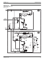
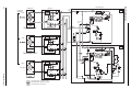
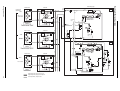
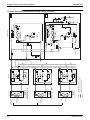
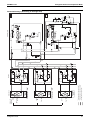
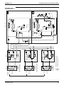
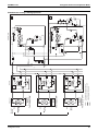
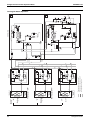
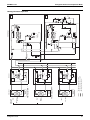
1. Refrigerant Circuit .................................................................................58
1.1
1.2
1.3
1.4
1.5
1.6
1.7
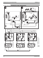
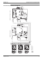
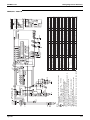
REYQ8P, 10P, 12P ................................................................................58
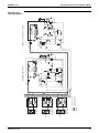
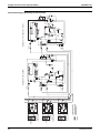
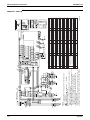
REYQ14P, 16P ......................................................................................60
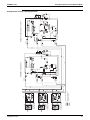
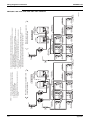
REMQ8P (Multi 8HP) .............................................................................62
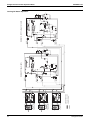
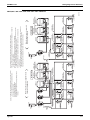
REMQ10P, 12P (Multi 10, 12HP)...........................................................64
REMQ14P, 16P (Multi 14, 16HP)...........................................................66
BS Unit Functional Parts ........................................................................68
Indoor Units ............................................................................................69
2. Functional Parts Layout ........................................................................70
2.1
2.2
2.3
2.4
2.5
REYQ8P, 10P, 12P ................................................................................70
REYQ14P, 16P ......................................................................................71
REMQ8P ................................................................................................72
REMQ10P, 12P......................................................................................73
REMQ14P, 16P......................................................................................74
3. Refrigerant Flow for Each Operation Mode...........................................75
Part 4 Function.......................................................................... 103
1. Function General.................................................................................104
1.1 Symbol .................................................................................................104
1.2 Operation Mode....................................................................................106
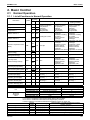
2. Basic Control.......................................................................................107
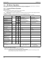
2.1 Normal Operation .................................................................................107
2.2 Compressor PI Control.........................................................................108
Table of Contents
i
SiENBE37-704
2.3
2.4
2.5
2.6
Electronic Expansion Valve PI Control.................................................116
Step Control of Outdoor Unit Fans .......................................................116
Outdoor Unit Fan Control in Cooling Operation ...................................117
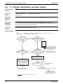
Heat Exchanger Control .......................................................................118
3. Special Control....................................................................................119
3.1
3.2
3.3
3.4
3.5
3.6
3.7
Startup Control .....................................................................................119
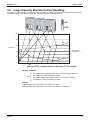
Large Capacity Start Up Control (Heating)...........................................121
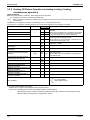
Oil Return Operation ............................................................................122
Defrost Operation .................................................................................126
Pump-down Residual Operation ..........................................................128
Standby ................................................................................................130
Stopping Operation ..............................................................................131
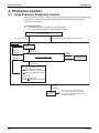
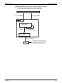
4. Protection Control ...............................................................................132
4.1
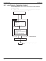
4.2
4.3
4.4
4.5
High Pressure Protection Control.........................................................132
Low Pressure Protection Control..........................................................134
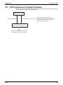
Discharge Pipe Protection Control .......................................................136
Inverter Protection Control ...................................................................137
STD Compressor Overload Protection.................................................139
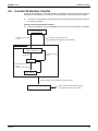
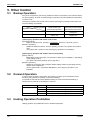
5. Other Control.......................................................................................140
5.1 Backup Operation.................................................................................140
5.2 Demand Operation ...............................................................................140
5.3 Heating Operation Prohibition ..............................................................140
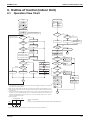
6. Outline of Control (Indoor Unit) ...........................................................141
6.1
6.2
6.3
6.4
6.5
6.6
6.7
6.8
6.9
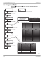
Operation Flow Chart ...........................................................................141
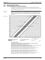
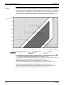
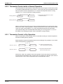
Thermostat Control...............................................................................143
Drain Pump Control..............................................................................147
Control of Electronic Expansion Valve .................................................149
Freeze Prevention ................................................................................150
Heater Control (Optional PC Board KRP1B...is required.) ...................151
List of Swing Flap Operations ..............................................................152
Hot Start Control (In Heating Operation Only)......................................153
Louver Control for Preventing Ceiling Dirt............................................154
Part 5 Test Operation ............................................................... 155
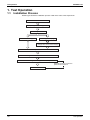
1. Test Operation ....................................................................................156
1.1 Installation Process ..............................................................................156
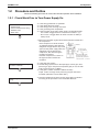
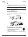
1.2 Procedure and Outline .........................................................................157
1.3 Operation when Power is Turned On ...................................................200
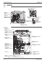
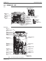
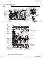
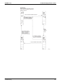
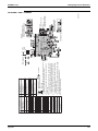
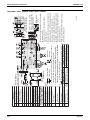
2. Outdoor Unit PC Board Layout ...........................................................201
3. Field Setting ........................................................................................202
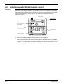
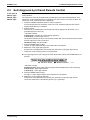
3.1 Field Setting from Remote Control .......................................................202
3.2 Field Setting from Outdoor Unit............................................................215
ii
Table of Contents
SiENBE37-704
Part 6 Troubleshooting ............................................................. 245
1. Symptom-based Troubleshooting .......................................................248
2. Troubleshooting by Remote Control ...................................................251
2.1
2.2
2.3
2.4
2.5
2.6
2.7
The INSPECTION / TEST Button.........................................................251
Self-diagnosis by Wired Remote Control .............................................252
Self-diagnosis by Infrared Remote Control ..........................................253
Inspection Mode ...................................................................................256
Remote Control Service Mode .............................................................257
Test Run Mode.....................................................................................259
Remote Control Self-Diagnosis Function .............................................259
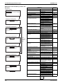
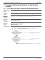
3. Troubleshooting by Indication on the Remote Control ........................266
3.1
3.2
3.3
3.4
3.5
3.6
3.7
3.8
3.9
3.10
3.11
3.12
3.13
3.14
3.15
3.16
3.17
3.18
3.19
3.20
3.21
3.22
3.23
3.24
3.25
3.26
3.27
3.28
Table of Contents
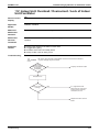
A0 Indoor Unit: Error of External Protection Device ...........................266
A1 Indoor Unit: PC Board Defect.........................................................267
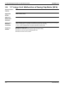
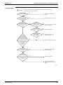
A3 Indoor Unit: Malfunction of Drain Level Control System (S1L) ......268
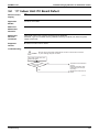
A6 Indoor Unit: Fan Motor (M1F) Lock, Overload...............................270
A6 Indoor Unit: Malfunction of Indoor Unit Fan Motor.........................272
A6 Indoor Uint: Overload / Overcurrent /
Lock of Indoor Unit Fan Motor..............................................................273
A7 Indoor Unit: Malfunction of Swing Flap Motor (M1S) .....................274
A9 Electronic Expansion Valve Malfunction / Dust Clogging ..............276
A9 Indoor Unit: Malfunction of Electronic Expansion Valve Coil.........278
AF Indoor Unit: Drain Level above Limit..............................................280
AJ Indoor Unit: Malfunction of Capacity Determination Device ..........281
C4 Indoor Unit: Malfunction of Thermistor (R2T) for
Heat Exchanger....................................................................................282
C5 Indoor Unit: Malfunction of Thermistor (R3T) for Gas Pipes..........283
C9 Indoor Unit: Malfunction of Thermistor (R1T) for Suction Air.........284
CJ Indoor Unit: Malfunction of Thermostat Sensor
in Remote Control ................................................................................285
E1 Outdoor Unit: PC Board Defect ......................................................286
E3 Outdoor Unit: Actuation of High Pressure Switch ..........................287
E4 Outdoor Unit: Actuation of Low Pressure Sensor ..........................289
E5 Outdoor Unit: Inverter Compressor Motor Lock.............................291
E6 Outdoor Unit: STD Compressor Motor Overcurrent/Lock..............293
E7 Outdoor Unit: Malfunction of Outdoor Unit Fan Motor ...................294
E9 Outdoor Unit: Malfunction of Moving Part of Electronic Expansion
Valve (Y1E~Y5E) .................................................................................297
F3 Outdoor Unit: Abnormal Discharge Pipe Temperature ..................299
F6 Outdoor Unit: Refrigerant Overcharged.........................................301
F9 Outdoor Unit : Malfunction of
BS Unit Electronic Expansion Valve.....................................................302
H7 Outdoor Unit: Abnormal Outdoor Fan Motor Signal.......................304
H9 Outdoor Unit: Malfunction of Thermistor (R1T) for Outdoor Air.....306
J2 Outdoor Unit: Current Sensor Malfunction ....................................307
J3 Outdoor Unit: Malfunction of Discharge Pipe Thermistor
(R31T, R32T, R33T).............................................................................308
J4 Outdoor Unit: Malfunction of Temperature Sensor for
Heat Exchanger Gas (R2T or R11T)....................................................309
J5 Outdoor Unit: Malfunction of Thermistor (R8T or R10T) for
Suction Pipe .........................................................................................310
iii
SiENBE37-704
3.29 J6 Outdoor Unit: Malfunction of Thermistor (R4T or R12T) for
Outdoor Unit Heat Exchanger ..............................................................311
3.30 J7 Outdoor Unit: Malfunction of Liquid Pipe Thermistor 1
(R6T, R9T or R14T) .............................................................................312
3.31 J8 Outdoor Unit: Malfunction of Liquid Pipe Thermistor 2
(R7T or R15T) ......................................................................................313
3.32 J9 Outdoor Unit: Malfunction of Subcooling Heat Exchanger Gas Pipe
Thermistor (R5T or R13T) ....................................................................314
3.33 JA Outdoor Unit: Malfunction of High Pressure Sensor......................315
3.34 JC Outdoor Unit: Malfunction of Low Pressure Sensor.......................317
3.35 L1 Outdoor Unit: Defective Inverter PC Board ....................................319
3.36 L4 Outdoor Unit: Malfunction of Inverter Radiating
Fin Temperature Rise...........................................................................321
3.37 L5 Outdoor Unit: Momentary Overcurrent of
Inverter Compressor.............................................................................324
3.38 L8 Outdoor Unit: Momentary Overcurrent of
Inverter Compressor.............................................................................326
3.39 L9 Outdoor Unit: Inverter Compressor Starting Failure ......................328
3.40 LC Outdoor Unit: Malfunction of Transmission between Inverter and
Control PC Board .................................................................................331
3.41 P1 Outdoor Unit: Inverter Over-Ripple Protection ...............................334
3.42 P4 Outdoor Unit: Malfunction of Inverter Radiating
Fin Temperature Rise Sensor ..............................................................336
3.43 PJ Outdoor Unit: Faulty Field Setting after Replacing Main PC Board
or Faulty Combination of PC Board......................................................338
3.44 U0 Outdoor Unit: Gas Shortage Alert .................................................340
3.45 U1 Reverse Phase, Open Phase.........................................................342
3.46 U2 Outdoor Unit: Power Supply Insufficient or
Instantaneous Failure...........................................................................343
3.47 U3 Outdoor Unit: Check Operation not Executed ...............................346
3.48 U4 Malfunction of Transmission between Indoor Units.......................347
3.49 U5 Indoor Unit: Malfunction of Transmission between
Remote Control and Indoor Unit...........................................................350
3.50 U7 Outdoor Unit: Transmission Failure (Across Outdoor Units) .........351
3.51 U8 Indoor Unit: Malfunction of Transmission between Main and
Sub Remote Controls ...........................................................................357
3.52 U9 Indoor Unit: Malfunction of Transmission between Indoor and
Outdoor Units in the Same System ......................................................358
3.53 UA Improper Combination of Indoor and Outdoor Units,
Indoor Units and Remote Control.........................................................359
3.54 UC Address Duplication of Centralized Controller ...............................365
3.55 UE Malfunction of Transmission between Centralized Controller and
Indoor Unit............................................................................................366
3.56 UF System is not Set yet .....................................................................369
3.57 UH Malfunction of System,
Refrigerant System Address Undefined ...............................................370
4. Troubleshooting (OP: Central Remote Control) ..................................372
4.1 M1 PC Board Defect ............................................................................372
4.2 M8 Malfunction of Transmission between Optional Controllers for
Centralized Control...............................................................................373
4.3 MA Improper Combination of Optional Controllers for
Centralized Control...............................................................................374
iv
Table of Contents
SiENBE37-704
4.4 MC Address Duplication, Improper Setting ..........................................376
5. Troubleshooting (OP: Unified ON/OFF Controller) .............................377
5.1 Operation Lamp Blinks .........................................................................377
5.2 Display Under Centralized Control Blinks
(Repeats Single Blink)..........................................................................379
5.3 Display Under Centralized Control Blinks
(Repeats Double Blink) ........................................................................382
Part 7 Appendix......................................................................... 397
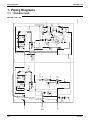
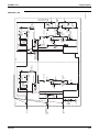
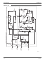
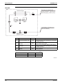
1. Piping Diagrams..................................................................................398
1.1 Outdoor Unit .........................................................................................398
1.2 Indoor Unit............................................................................................403
1.3 BS Unit .................................................................................................409
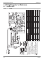
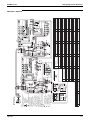
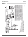
2. Wiring Diagrams for Reference...........................................................410
2.1
2.2
2.3
2.4
Outdoor Unit .........................................................................................410
Field Wiring ..........................................................................................415
Indoor Unit............................................................................................418
BS Unit .................................................................................................434
3. List of Electrical and Functional Parts .................................................435
3.1 Outdoor Unit .........................................................................................435
3.2 Indoor Side ...........................................................................................439
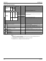
4. Option List ...........................................................................................445
4.1 Option List of Controllers......................................................................445
4.2 Option Lists (Outdoor Unit)...................................................................447
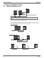
5. Piping Installation Point.......................................................................448
5.1 Piping Installation Point ........................................................................448
5.2 The Example of a Wrong Pattern .........................................................449
6.
7.
8.
9.
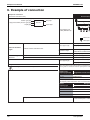
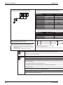
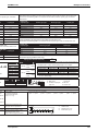
Example of connection (R-410A Type) ...............................................451
Thermistor Resistance / Temperature Characteristics........................455
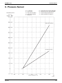
Pressure Sensor .................................................................................457
Method of Checking the Inverters Power Transistors and
Diode Modules ....................................................................................458
9.1 Method of Checking the Inverters Power Transistors and
Diode Modules .....................................................................................458
Part 8 Precautions for New Refrigerant (R-410A) .................... 461
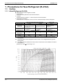
1. Precautions for New Refrigerant (R-410A) .........................................462
1.1 Outline ..................................................................................................462
1.2 Refrigerant Cylinders............................................................................464
1.3 Service Tools........................................................................................465
Index
............................................................................................. i
Drawings & Flow Charts ................................................................ v
Table of Contents
v
Introduction
SiENBE37-704
1. Introduction
1.1
Safety Cautions
Cautions and
Warnings
! Be sure to read the following safety cautions before conducting repair work.
! The caution items are classified into
Warning and
Caution. The
Warning
items are especially important since they can lead to death or serious injury if they are not
followed closely. The
Caution items can also lead to serious accidents under some
conditions if they are not followed. Therefore, be sure to observe all the safety caution items
described below.
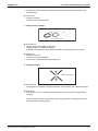
! About the pictograms
This symbol indicates an item for which caution must be exercised.
The pictogram shows the item to which attention must be paid.
This symbol indicates a prohibited action.
The prohibited item or action is shown inside or near the symbol.
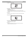
This symbol indicates an action that must be taken, or an instruction.
The instruction is shown inside or near the symbol.
! After the repair work is complete, be sure to conduct a test operation to ensure that the
equipment operates normally, and explain the cautions for operating the product to the
customer
1.1.1 Caution in Repair
Warning
Be sure to disconnect the power cable plug from the plug socket before
disassembling the equipment for a repair.
Working on the equipment that is connected to a power supply can cause an
electrical shook.
If it is necessary to supply power to the equipment to conduct the repair or
inspecting the circuits, do not touch any electrically charged sections of the
equipment.
If the refrigerant gas discharges during the repair work, do not touch the
discharging refrigerant gas.
The refrigerant gas can cause frostbite.
When disconnecting the suction or discharge pipe of the compressor at the
welded section, release the refrigerant gas completely at a well-ventilated
place first.
If there is a gas remaining inside the compressor, the refrigerant gas or
refrigerating machine oil discharges when the pipe is disconnected, and it can
cause injury.
If the refrigerant gas leaks during the repair work, ventilate the area. The
refrigerant gas can generate toxic gases when it contacts flames.
The step-up capacitor supplies high-voltage electricity to the electrical
components of the outdoor unit.
Be sure to discharge the capacitor completely before conducting repair work.
A charged capacitor can cause an electrical shock.
Do not start or stop the air conditioner operation by plugging or unplugging the
power cable plug.
Plugging or unplugging the power cable plug to operate the equipment can
cause an electrical shock or fire.
vi
SiENBE37-704
Introduction
Caution
Do not repair the electrical components with wet hands.
Working on the equipment with wet hands can cause an electrical shock.
Do not clean the air conditioner by splashing water.
Washing the unit with water can cause an electrical shock.
Be sure to provide the grounding when repairing the equipment in a humid or
wet place, to avoid electrical shocks.
Be sure to turn off the power switch and unplug the power cable when cleaning
the equipment.
The internal fan rotates at a high speed, and cause injury.
Do not tilt the unit when removing it.
The water inside the unit can spill and wet the furniture and floor.
Be sure to check that the refrigerating cycle section has cooled down
sufficiently before conducting repair work.
Working on the unit when the refrigerating cycle section is hot can cause burns.
Use the welder in a well-ventilated place.
Using the welder in an enclosed room can cause oxygen deficiency.
1.1.2 Cautions Regarding Products after Repair
Warning
Be sure to use parts listed in the service parts list of the applicable model and
appropriate tools to conduct repair work. Never attempt to modify the
equipment.
The use of inappropriate parts or tools can cause an electrical shock,
excessive heat generation or fire.
When relocating the equipment, make sure that the new installation site has
sufficient strength to withstand the weight of the equipment.
If the installation site does not have sufficient strength and if the installation
work is not conducted securely, the equipment can fall and cause injury.
Be sure to install the product correctly by using the provided standard
installation frame.
Incorrect use of the installation frame and improper installation can cause the
equipment to fall, resulting in injury.
Be sure to install the product securely in the installation frame mounted on a
window frame.
If the unit is not securely mounted, it can fall and cause injury.
Be sure to use an exclusive power circuit for the equipment, and follow the
technical standards related to the electrical equipment, the internal wiring
regulations and the instruction manual for installation when conducting
electrical work.
Insufficient power circuit capacity and improper electrical work can cause an
electrical shock or fire.
For integral units
only
For integral units
only
vii
Introduction
SiENBE37-704
Warning
Be sure to use the specified cable to connect between the indoor and outdoor
units. Make the connections securely and route the cable properly so that there
is no force pulling the cable at the connection terminals.
Improper connections can cause excessive heat generation or fire.
When connecting the cable between the indoor and outdoor units, make sure
that the terminal cover does not lift off or dismount because of the cable.
If the cover is not mounted properly, the terminal connection section can cause
an electrical shock, excessive heat generation or fire.
Do not damage or modify the power cable.
Damaged or modified power cable can cause an electrical shock or fire.
Placing heavy items on the power cable, and heating or pulling the power cable
can damage the cable.
Do not mix air or gas other than the specified refrigerant (R-410A) in the
refrigerant system.
If air enters the refrigerating system, an excessively high pressure results,
causing equipment damage and injury.
If the refrigerant gas leaks, be sure to locate the leak and repair it before
charging the refrigerant. After charging refrigerant, make sure that there is no
refrigerant leak.
If the leak cannot be located and the repair work must be stopped, be sure to
perform pump-down and close the service valve, to prevent the refrigerant gas
from leaking into the room. The refrigerant gas itself is harmless, but it can
generate toxic gases when it contacts flames, such as fan and other heaters,
stoves and ranges.
When replacing the coin battery in the remote control, be sure to disposed of
the old battery to prevent children from swallowing it.
If a child swallows the coin battery, see a doctor immediately.
Caution
Installation of a leakage breaker is necessary in some cases depending on the
conditions of the installation site, to prevent electrical shocks.
Do not install the equipment in a place where there is a possibility of
combustible gas leaks.
If a combustible gas leaks and remains around the unit, it can cause a fire.
For integral units
Be sure to install the packing and seal on the installation frame properly.
If the packing and seal are not installed properly, water can enter the room and only
wet the furniture and floor.
1.1.3 Inspection after Repair
Warning
Check to make sure that the power cable plug is not dirty or loose, then insert
the plug into a power outlet all the way.
If the plug has dust or loose connection, it can cause an electrical shock or fire.
If the power cable and lead wires have scratches or deteriorated, be sure to
replace them.
Damaged cable and wires can cause an electrical shock, excessive heat
generation or fire.
Do not use a joined power cable or extension cable, or share the same power
outlet with other electrical appliances, since it can cause an electrical shock,
excessive heat generation or fire.
viii
SiENBE37-704
Introduction
Caution
Check to see if the parts and wires are mounted and connected properly, and
if the connections at the soldered or crimped terminals are secure.
Improper installation and connections can cause excessive heat generation,
fire or an electrical shock.
If the installation platform or frame has corroded, replace it.
Corroded installation platform or frame can cause the unit to fall, resulting in
injury.
Check the grounding, and repair it if the equipment is not properly grounded.
Improper grounding can cause an electrical shock.
Be sure to measure the insulation resistance after the repair, and make sure
that the resistance is 1 Mohm or higher.
Faulty insulation can cause an electrical shock.
Be sure to check the drainage of the indoor unit after the repair.
Faulty drainage can cause the water to enter the room and wet the furniture
and floor.
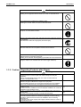
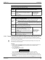
1.1.4 Using Icons
Icons are used to attract the attention of the reader to specific information. The meaning of each
icon is described in the table below:
1.1.5 Using Icons List
Icon
Type of
Information
Note
Description
A note provides information that is not indispensable, but may
nevertheless be valuable to the reader, such as tips and tricks.
Note:
Caution
A caution is used when there is danger that the reader, through
incorrect manipulation, may damage equipment, loose data, get
an unexpected result or has to restart (part of) a procedure.
Warning
A warning is used when there is danger of personal injury.
Reference
A reference guides the reader to other places in this binder or
in this manual, where he/she will find additional information on a
specific topic.
Caution
Warning
ix
Introduction
1.2
SiENBE37-704
PREFACE
Thank you for your continued patronage of Daikin products.
This is the new service manual for Daikin's Year 2007 VRVIII series Heat Recovery System.
Daikin offers a wide range of models to respond to building and office air conditioning needs.
We are confident that customers will be able to find the models that best suit their needs.
This service manual contains information regarding the servicing of VRVIII series R-410A Heat
Recovery System.
Jan., 2008
After Sales Service Division
x
SiENBE37-704
Part 1
General Information
1. Model Names of Indoor/Outdoor Units....................................................2
2. External Appearance...............................................................................3
2.1 Indoor Units ..............................................................................................3
2.2 Outdoor Units ...........................................................................................4
3. Combination of Outdoor Units.................................................................5
4. Model Selection.......................................................................................6
General Information
1
Model Names of Indoor/Outdoor Units
SiENBE37-704
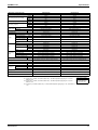
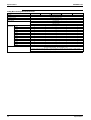
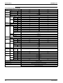
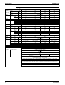
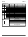
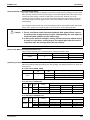
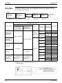
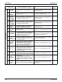
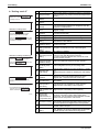
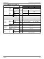
1. Model Names of Indoor/Outdoor Units
Indoor Units
Type
Power
Supply
Model Name
Roundflow Ceiling
Mounted Cassette
FXFQ
20P
25P
32P
40P
50P
63P
80P
100P
125P
VE
600×600 4-Way Blow
Ceiling Mounted
Cassette
FXZQ
20M
25M
32M
40M
50M
V1
2-Way Blow Ceiling
Mounted Cassette
FXCQ
20M
25M
32M
40M
50M
63M
80M
125M
V3
Ceiling Mounted
Corner Cassette
FXKQ
25MA
32MA
40MA
63MA
FXDQPVE
20P
25P
32P
FXDQNAVE
40NA
50NA
63NA
Concealed Ceiling Unit
(Small)
FXDQ
20M
25M
Concealed Ceiling Unit
FXSQ
20M
25M
32M
40M
50M
63M
80M
100M
125M
Concealed Ceiling Unit
(Large)
FXMQ
40MA
50MA
63MA
80MA
Slim Concealed Ceiling
Unit
Ceiling Suspended Unit FXHQ
VE
V3
100MA 125MA 200MA 250MA
32MA
63MA
100MA
20MA
25MA
32MA
40MA
50MA
63MA
FXLQ
20MA
25MA
32MA
40MA
50MA
63MA
FXNQ
20MA
25MA
32MA
40MA
50MA
63MA
4-way blow ceiling
suspended unit
FXUQ
71MA
100MA
125MA
V1
Connection Unit for
FXUQ
BEVQ
71MA
100MA
125MA
VE
Wall Mounted Unit
FXAQ
Floor Standing Unit
Concealed Floor
Standing Unit
VE
Note: FXDQ has following 2 Series, as show below.
FXDQ-P, NAVE: with Drain Pump
BEV unit is required for FXUQ only.
MA, NA: RoHS Directive models; Specifications, Dimensions and other functions are not changed compared
with M, N type.
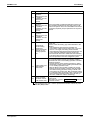
BS Units
Type
Heat Recovery Series
BSVQ
Model Name
160P
100P
Power Supply
V1
250P
Outdoor Units
Normal Series
Series
Heat Recovery
REYQ
Power Supply:
2
8P
26P
44P
10P
28P
46P
12P
30P
48P
Model Name
14P
16P
32P
34P
Power Supply
18P
36P
20P
38P
22P
40P
24P
42P
Y1
VE : 1φ, 220~240V, 50Hz, 1φ, 220V, 60Hz
V1 : 1φ, 220~240V, 50Hz
V3 : 1φ, 230V, 50Hz
Y1 : 3φ, 380~415V, 50Hz
General Information
SiENBE37-704
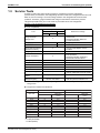
External Appearance
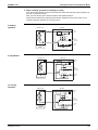
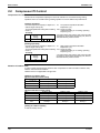
2. External Appearance
2.1
Indoor Units
Roundflow Ceiling Mounted Cassette
FXFQ20P
FXFQ25P
FXFQ32P
FXFQ40P
FXFQ50P
FXFQ63P
FXFQ80P
FXFQ100P
FXFQ125P
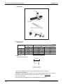
600×600 4-Way Blow
Ceiling Mounted Cassette
FXZQ20M
FXZQ25M
FXZQ32M
FXZQ40M
FXZQ50M
2-Way Blow Ceiling Mounted Cassette
FXCQ20M
FXCQ25M
FXCQ32M
FXCQ40M
FXCQ50M
FXCQ63M
FXCQ80M
FXCQ125M
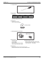
Ceiling Mounted Corner Cassette
FXKQ25MA
FXKQ32MA
FXKQ40MA
FXKQ63MA
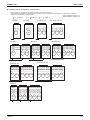
Slim Concealed Ceiling Unit
FXDQ20P FXDQ40NA
FXDQ25P FXDQ50NA
FXDQ32P FXDQ63NA
with Drain Pump (VE)
Concealed Ceiling Unit (Small)
FXDQ20M
FXDQ25M
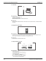
Concealed Ceiling Unit
FXSQ20M
FXSQ25M
FXSQ32M
FXSQ40M
FXSQ50M
FXSQ63M
FXSQ80M
FXSQ100M
FXSQ125M
General Information
Concealed Ceiling Unit
(Large)
FXMQ40MA
FXMQ50MA
FXMQ63MA
FXMQ80MA
FXMQ100MA
FXMQ125MA
FXMQ200MA
FXMQ250MA
FXMQ40~125M
FXMQ200 · 250M
Ceiling Suspended Unit
FXHQ32MA
FXHQ63MA
FXHQ100MA
Wall Mounted Unit
FXAQ20MA
FXAQ25MA
FXAQ32MA
FXAQ40MA
FXAQ50MA
FXAQ63MA
Floor Standing Unit
FXLQ20MA
FXLQ25MA
FXLQ32MA
FXLQ40MA
FXLQ50MA
FXLQ63MA
Concealed Floor Standing Unit
FXNQ20MA
FXNQ25MA
FXNQ32MA
FXNQ40MA
FXNQ50MA
FXNQ63MA
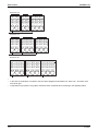
BS Units
BSVQ100P
BSVQ160P
BSVQ250P
4-way blow ceiling suspended unit
(Connection Unit Series)
FXUQ71MA +
FXUQ100MA +
FXUQ125MA +
BEVQ71MA
BEVQ100MA
BEVQ125MA
Connection Unit
3
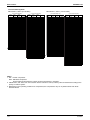
External Appearance
2.2
4
SiENBE37-704
Outdoor Units
REYQ8P, 10P, 12P, 14P, 16P
REYQ18P, 20P, 22P, 24P
8, 10, 12, 14, 16 HP
22.4 ~ 40.0, 45.0 kW
18, 20, 22, 24 HP
50.4 ~ 67.0 kW
REYQ26P, 28P
REYQ30P, 32P
26, 28 HP
73.0, 78.5 kW
30, 32 HP
85.0, 90.0 kW
REYQ34P, 36P, 38P, 40P
34, 36, 38, 40 HP
95.4 ~ 112 kW
REYQ42P, 44P
REYQ46P, 48P
42, 44 HP
118 ~ 124 kW
46, 48 HP
130, 135 kW
General Information
SiENBE37-704
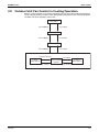
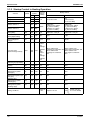
Combination of Outdoor Units
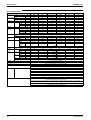
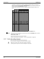
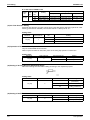
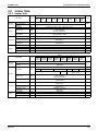
3. Combination of Outdoor Units
Single Use
System Number
Capacity of units
8HP
1
10HP
1
12HP
1
14HP
1
16HP
1
8
l
10
Single Unit
12
14
16
Outdoor Unit Multi Connection
Piping Kit (Option)
l
l
l
l
Multiple Use
System Number
Capacity of units
18HP
2
20HP
2
22HP
2
24HP
2
26HP
2
28HP
2
30HP
2
32HP
2
34HP
3
36HP
3
38HP
3
40HP
3
42HP
3
44HP
3
46HP
3
48HP
3
Note:
General Information
8
l
l
l
l
Multi Unit Module
10
12
14
l
l
l
l
ll
l
l
l
l
l
l
l
ll
l
l
l
16
l
l
l
ll
l
l
l
l
ll
ll
ll
lll
Outdoor Unit Multi Connection
Piping Kit (Option)
Heat Recovery: BHFP26P90
Heat Recovery: BHFP26P136
For multiple connection of 18HP system or more, an optional Daikin Outdoor Unit Multi
Connection Piping Kit is required.
5
Model Selection
SiENBE37-704
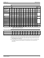
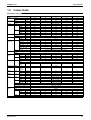
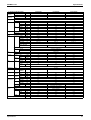
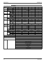
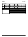
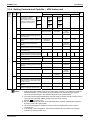
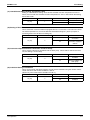
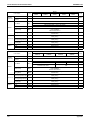
4. Model Selection
VRV III Heat Recovery Series
Connectable indoor units number and capacity
Normal Series
8HP
10HP
12HP
14HP
16HP
18HP
20HP
System name
HP
REYQ8P
REYQ10P
REYQ12P
REYQ14P
REYQ16P
REYQ18P
REYQ20P
Outdoor unit 1
REYQ8P
REYQ10P
REYQ12P
REYQ14P
REYQ16P
REMQ8P
REMQ8P
Outdoor unit 2
REMQ10P
REMQ12P
Outdoor unit 3
Total number of connectable
indoor units
13
16
19
22
26
29
32
Total capacity of connectable
indoor units (kW)
10.0~26.0
12.5~32.5
15.0~39.0
17.5~45.5
20.0~52.0
22.5~58.5
25.0~65.0
22HP
24HP
26HP
28HP
30HP
32HP
34HP
System name
HP
REYQ22P
REYQ24P
REYQ26P
REYQ28P
REYQ30P
REYQ32P
REYQ34P
Outdoor unit 1
REMQ10P
REMQ12P
REMQ10P
REMQ12P
REMQ14P
REMQ16P
REMQ8P
Outdoor unit 2
REMQ12P
REMQ12P
REMQ16P
REMQ16P
REMQ16P
REMQ16P
REMQ10P
Outdoor unit 3
REMQ16P
Total number of connectable
indoor units
35
39
42
45
48
52
55
Total capacity of connectable
indoor units (kW)
27.5~71.5
30.0~78.0
32.5~84.5
35.0~91.0
37.5~97.5
40.0~104.0
42.5~110.5
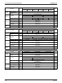
36HP
38HP
40HP
42HP
44HP
46HP
48HP
System name
HP
REYQ36P
REYQ38P
REYQ40P
REYQ42P
REYQ44P
REYQ46P
REYQ48P
Outdoor unit 1
REMQ8P
REMQ10P
REMQ12P
REMQ10P
REMQ12P
REMQ14P
REMQ16P
Outdoor unit 2
REMQ12P
REMQ12P
REMQ12P
REMQ16P
REMQ16P
REMQ16P
REMQ16P
Outdoor unit 3
REMQ16P
REMQ16P
REMQ16P
REMQ16P
REMQ16P
REMQ16P
REMQ16P
Total number of connectable
indoor units
58
61
Total capacity of connectable
indoor units (kW)
45.0~117.0
47.5~123.5
57.5~149.5
60.0~156.0
6
64
50.0~130.0
52.5~136.5
55.0~143.0
General Information
SiENBE37-704
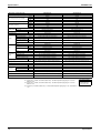
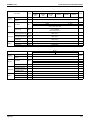
Model Selection
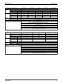
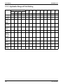
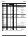
Connectable Indoor Unit
Type
Power
Supply
Model Name
Roundflow Ceiling
Mounted Cassette
FXFQ
20P
25P
32P
40P
50P
63P
80P
100P
125P
VE
600×600 4-Way Blow
Ceiling Mounted
Cassette
FXZQ
20M
25M
32M
40M
50M
V1
2-Way Blow Ceiling
Mounted Cassette
FXCQ
20M
25M
32M
40M
50M
63M
80M
125M
V3
Ceiling Mounted
Corner Cassette
FXKQ
25MA
32MA
40MA
63MA
FXDQPVE
20P
25P
32P
FXDQNAVE
40NA
50NA
63NA
Concealed Ceiling Unit
(Small)
FXDQ
20M
25M
Concealed Ceiling Unit
FXSQ
20M
25M
32M
40M
50M
63M
80M
100M
125M
Concealed Ceiling Unit
(Large)
FXMQ
40MA
50MA
63MA
80MA
100MA
125MA
200MA
250MA
Slim Concealed Ceiling
Unit
Ceiling Suspended Unit FXHQ
VE
V3
32MA
63MA
100MA
Wall Mounted Unit
FXAQ
20MA
25MA
32MA
40MA
50MA
63MA
Floor Standing Unit
FXLQ
20MA
25MA
32MA
40MA
50MA
63MA
Concealed Floor
Standing Unit
FXNQ
20MA
25MA
32MA
40MA
50MA
63MA
4-way blow ceiling
suspended unit
FXUQ
71MA
100MA
125MA
V1
Connection Unit for
FXUQ
BEVQ
71MA
100MA
125MA
VE
VE
Note: FXDQ has following 2 Series, as shown below.
FXDQ-P, NAVE : with Drain Pump
BEV unit is required for FXUQ only.
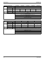
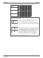
Indoor unit capacity
New refrigerant model code
Selecting model capacity
Equivalent output
P20
type
P25
type
P32
type
P40
type
P50
type
P63
type
P80
type
P100
type
P125
type
P200
type
P250
type
2.2
kW
0.8HP
2.8
kW
1HP
3.5
kW
4.5
kW
1.6HP
5.6
kW
2.0HP
7.0
kW
2.5HP
9.0
kW
3.2HP
11.2
kW
4HP
14.0
kW
5HP
22.4
kW
8HP
28.0
kW
10HP
1.25HP
Use the above tables to determine the capacities of indoor units to be connected. Make sure the
total capacity of indoor units connected to each outdoor unit is within the specified value (kW).
! The total capacity of connected indoor units must be within a range of 50 to 130% of the
rated capacity of the outdoor unit.
! In some models, it is not possible to connect the maximum number of connectable indoor
units. Select models so the total capacity of connected indoor units conforms to the
specification.
General Information
7
Model Selection
SiENBE37-704
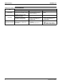
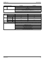
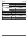
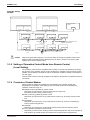
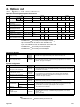
Differences from Conventional Models
Item
Compressor
Workability
Object
Connection of equalizer oil pipe
Conventional model (M Model)
" YES
Equalizer oil pipe for multioutdoor-unit system
" NONE
Procedure for calculating
refrigerant refilling quantity
" Refilling quantity due to piping " Refilling quantity due to piping
length + Adjustment quantity
length - Adjustment quantity
according to models of
according to models of
outdoor units
outdoor units
Branch pipe for outdoor unit
Optional accessories
connection
8
Differences
New model (P Model)
" NONE
(No particular changes in
terms of service)
" Y branch
Type: BHFP26P90/136
" YES
" T branch
Type:
BHFP26M90+BHFP22M90P
BHFP26M135+BHFP22M135P
General Information
SiENBE37-704
Part 2
Specifications
1. Specifications ........................................................................................10
1.1 Outdoor Units .........................................................................................10
1.2 Indoor Units ............................................................................................21
1.3 BS Units .................................................................................................56
Specifications
9
Specifications
SiENBE37-704
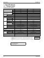
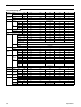
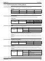
1. Specifications
1.1
Outdoor Units
Heat Recovery 50Hz <REYQ-P>
Model Name
H1 Cooling Capacity (19.5°CWB)
REYQ8P8Y1B
REYQ10P8Y1B
kcal / h
19,400
24,300
Btu / h
76,800
96,200
kW
22.5
28.2
kW
22.4
28.0
kcal / h
21,500
27,100
Btu / h
85,300
107,000
kW
25.0
31.5
Ivory White 5Y7.5/1
Ivory White 5Y7.5/1
Light Camel 2.5Y6.5/1.5
Light Camel 2.5Y6.5/1.5
1680×1300×765
1680×1300×765
H2 Cooling Capacity (19.0°CWB)
H3 Heating Capacity
Casing Color
Y1 Type
Y1E Type
Dimensions: (H×W×D)
mm
Heat Exchanger
Type
Comp.
Cross Fin Coil
Cross Fin Coil
Hermetically Sealed Scroll Type
Hermetically Sealed Scroll Type
Piston Displacement
m³/h
7.88+10.53
13.34+10.53
Number of Revolutions
r.p.m
3720, 2900
6300, 2900
Motor Output×Number
of Units
kW
1.0+4.5
2.2+4.5
Starting Method
Soft Start
Soft Start
Propellor Fan
Propellor Fan
kW
0.35×2
0.35×2
I/s
3,166
3,166
m³/min
190
190
Direct Drive
Direct Drive
Type
Motor Output
Fan
Air Flow Rate
Drive
Connecting
Pipes
Liquid Pipe
φ9.5 C1220T (Brazing Connection)
φ9.5 C1220T (Brazing Connection)
Suction Gas Pipe
φ19.1 C1220T (Brazing Connection)
φ22.2 C1220T (Brazing Connection)
High and Low Pressure Gas Pipe
φ15.9 C1220T (Brazing Connection)
φ19.1 C1220T (Brazing Connection)
Pressure Equalizer Tube
Mass (Weight)
331
331
High Pressure Switch, Fan Driver Overload Protector, Over
Current Relay, Inverter Overload Protector
High Pressure Switch, Fan Driver Overload Protector, Over
Current Relay, Inverter Overload Protector
kg
Safety Devices
Defrost Method
Capacity Control
%
Refrigerant Name
Refrigerant
Charge
kg
Control
Refrigerator Oil
Deicer
Deicer
20~100
14~100
R-410A
R-410A
10.3
10.6
Electronic Expansion Valve
Electronic Expansion Valve
Refer to the nameplate of compressor
Installation Manual, Operation Manual, Connection Pipes,
Clamps
Standard Accessories
Drawing No.
4D057563B
Refer to the nameplate of compressor
Installation Manual, Operation Manual, Connection Pipes,
Clamps
4D057564B
Notes:
H1 Indoor temp. : 27°CDB, 19.5°CWB / outdoor temp. : 35°CDB / Equivalent piping length : 7.5m, level
difference : 0m.
H2 Indoor temp. : 27°CDB, 19.0°CWB / outdoor temp. : 35°CDB / Equivalent piping length : 7.5m, level
difference : 0m.
H3 Indoor temp. : 20°CDB / outdoor temp. : 7°CDB, 6°CWB / Equivalent piping length : 7.5m, level difference
: 0m.
Conversion Formulae
kcal/h=kW×860
Btu/h=kW×3412
cfm=m³/min×35.3
The Reference Number
C~: Partly corrected drawings.
J~ : Original drawing is Japanese
V~ : Printing Convenience
10
Specifications
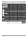
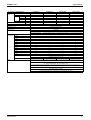
SiENBE37-704
Specifications
Model Name
REYQ12P8Y1B
REYQ14P8Y1B
kcal / h
29,000
35,500
H1 Cooling Capacity (19.5°CWB)
Btu / h
115,000
141,000
kW
33.7
41.3
H2 Cooling Capacity (19.0°CWB)
kW
33.5
40.0
kcal / h
32,300
38,700
Btu / h
128,000
154,000
kW
37.5
45.0
Ivory White 5Y7.5/1
Ivory White 5Y7.5/1
Light Camel 2.5Y6.5/1.5
Light Camel 2.5Y6.5/1.5
1680×1300×765
1680×1300×765
H3 Heating Capacity
Casing Color
Y1 Type
Y1E Type
Dimensions: (H×W×D)
mm
Heat Exchanger
Type
Comp.
m³/h
13.34+10.53
16.90+16.90
r.p.m
6300, 2900
7980, 7980
Motor Output×Number
of Units
kW
3.3+4.5
3.8+3.8
Soft Start
Soft Start
Propellor Fan
Propellor Fan
kW
0.35×2
0.75×2
I/s
3,500
3,916
m³/min
210
235
Direct Drive
Direct Drive
Motor Output
Air Flow Rate
Drive
Liquid Pipe
φ12.7 C1220T (Brazing Connection)
φ12.7 C1220T (Brazing Connection)
Suction Gas Pipe
φ28.6 C1220T (Brazing Connection)
φ28.6 C1220T (Brazing Connection)
High and Low Pressure Gas Pipe
φ19.1 C1220T (Brazing Connection)
φ22.2 C1220T (Brazing Connection)
Pressure Equalizer Tube
Mass (Weight)
kg
Safety Devices
Defrost Method
Capacity Control
%
Refrigerant Name
Refrigerant
Hermetically Sealed Scroll Type
Number of Revolutions
Starting Method
Connecting
Pipes
Cross Fin Coil
Hermetically Sealed Scroll Type
Piston Displacement
Type
Fan
Cross Fin Coil
Charge
kg
Control
Refrigerator Oil
331
339
High Pressure Switch, Fan Driver Overload Protector, Over
Current Relay, Inverter Overload Protector
High Pressure Switch, Fan Driver Overload Protector, Over
Current Relay, Inverter Overload Protector
Deicer
Deicer
14~100
10~100
R-410A
R-410A
10.8
11.1
Electronic Expansion Valve
Electronic Expansion Valve
Refer to the nameplate of compressor
Installation Manual, Operation Manual, Connection Pipes,
Clamps
Standard Accessories
Drawing No.
4D057565B
Refer to the nameplate of compressor
Installation Manual, Operation Manual, Connection Pipes,
Clamps
4D057566B
Notes:
H1 Indoor temp. : 27°CDB, 19.5°CWB / outdoor temp. : 35°CDB / Equivalent piping length : 7.5m, level
difference : 0m.
H2 Indoor temp. : 27°CDB, 19.0°CWB / outdoor temp. : 35°CDB / Equivalent piping length : 7.5m, level
difference : 0m.
H3 Indoor temp. : 20°CDB / outdoor temp. : 7°CDB, 6°CWB / Equivalent piping length : 7.5m, level difference
: 0m.
Specifications
Conversion Formulae
kcal/h=kW×860
Btu/h=kW×3412
cfm=m³/min×35.3
11
Specifications
SiENBE37-704
Model Name
REYQ16P8Y1B
kcal / h
40,000
H1 Cooling Capacity (19.5°CWB)
Btu / h
159,000
kW
46.5
H2 Cooling Capacity (19.0°CWB)
kW
45.0
H3 Heating Capacity
kcal / h
43,000
Btu / h
171,000
kW
Casing Color
Y1 Type
Y1E Type
Light Camel 2.5Y6.5/1.5
Dimensions: (H×W×D)
mm
Heat Exchanger
Hermetically Sealed Scroll Type
Piston Displacement
m³/h
16.90+16.90
Number of Revolutions
r.p.m
7980, 7980
Motor Output×Number
of Units
kW
4.4+4.4
Starting Method
Soft Start
Type
Propellor Fan
Motor Output
Fan
Air Flow Rate
kW
0.75×2
I/s
4,000
m³/min
Drive
Connecting
Pipes
240
Direct Drive
Liquid Pipe
φ12.7 C1220T (Brazing Connection)
Suction Gas Pipe
φ28.6 C1220T (Brazing Connection)
High and Low Pressure Gas Pipe
φ22.2 C1220T (Brazing Connection)
Pressure Equalizer Tube
Mass (Weight)
kg
Safety Devices
339
High Pressure Switch, Fan Driver Overload Protector, Over Current Relay, Inverter Overload Protector
Defrost Method
Deicer
Capacity Control
%
Refrigerant Name
Refrigerant
1680×1300×765
Cross Fin Coil
Type
Comp.
50.0
Ivory White 5Y7.5/1
Charge
R-410A
kg
Control
10~100
11.1
Electronic Expansion Valve
Refrigerator Oil
Refer to the nameplate of compressor
Standard Accessories
Installation Manual, Operation Manual, Connection Pipes, Clamps
Drawing No.
4D057567B
Notes:
H1 Indoor temp. : 27°CDB, 19.5°CWB / outdoor temp. : 35°CDB / Equivalent piping length : 7.5m, level
difference : 0m.
H2 Indoor temp. : 27°CDB, 19.0°CWB / outdoor temp. : 35°CDB / Equivalent piping length : 7.5m, level
difference : 0m.
H3 Indoor temp. : 20°CDB / outdoor temp. : 7°CDB, 6°CWB / Equivalent piping length : 7.5m, level difference
: 0m.
12
Conversion Formulae
kcal/h=kW×860
Btu/h=kW×3412
cfm=m³/min×35.3
Specifications
SiENBE37-704
Specifications
Model Name (Combination Unit)
REYQ18P8Y1B
REYQ20P8Y1B
Model Name (Independent Unit)
REMQ8P8Y1B+REMQ10P8Y1B
REMQ8P8Y1B+REMQ12P8Y1B
kcal / h
43,600
48,300
H1 Cooling Capacity (19.5°CWB)
Btu / h
173,000
192,000
kW
50.7
56.2
H2 Cooling Capacity (19.0°CWB)
kW
50.4
55.9
kcal / h
48,600
53,800
Btu / h
193,000
213,000
kW
56.5
62.5
Ivory White 5Y7.5/1
Ivory White 5Y7.5/1
H3 Heating Capacity
Casing Color
Y1 Type
Y1E Type
Dimensions: (H×W×D)
mm
Heat Exchanger
Type
Comp.
Cross fin coil
Hermetically sealed scroll type
m³/h
(13.34+10.53)+16.90
(13.34+10.53)+16.90
r.p.m
(6300, 2900), 7980
(6300, 2900), 7980
Motor Output×Number
of Units
kW
(2.2+4.5)×1+4.7×1
(3.5+4.5)×1+4.7×1
Soft start
Soft start
Propellor fan
Propellor fan
kW
(0.75×1)+(0.75×1)
(0.75×1)+(0.75×1)
I/s
3,000+3,083
3,000+3,333
m³/min
180+185
180+200
Direct drive
Direct drive
Motor Output
Air Flow Rate
Drive
Liquid Pipe
φ15.9 C1220T (Brazing connection)
φ15.9 C1220T (Brazing connection)
Suction Gas Pipe
φ28.6 C1220T (Brazing connection)
φ28.6 C1220T (Brazing connection)
High and Low Pressure Gas Pipe
φ22.2 C1220T (Brazing connection)
φ28.6 C1220T (Brazing connection)
Pressure Equalizer Tube
φ19.1 C1220T (Brazing connection)
φ19.1 C1220T (Brazing connection)
Mass (Weight)
kg
Safety Devices
Defrost Method
Capacity Control
%
Refrigerant Name
Refrigerant
Cross fin coil
Hermetically sealed scroll type
Number of Revolutions
Type
Connecting
Pipes
Light Camel 2.5Y6.5/1.5
1680×930×765+1680×930×765
Piston Displacement
Starting Method
Fan
Light Camel 2.5Y6.5/1.5
1680×930×765+1680×930×765
Charge
kg
Control
Refrigerator Oil
204+254
204+254
High pressure switch, fan driver overload protector,
overcurrent relay, inverter overload protector
High pressure switch, fan driver overload protector,
overcurrent relay, inverter overload protector
Deicer
Deicer
9~100
7~100
R-410A
R-410A
8.2+9.0
8.2+9.1
Electronic expansion valve
Electronic expansion valve
Refer to the nameplate of compressor
Installation manual, Operation manual, Connection pipes,
Cramps
Standard Accessories
Drawing No.
4D057568A
Refer to the nameplate of compressor
Installation manual, Operation manual, Connection pipes,
Cramps
4D057569A
Notes:
H1 Indoor temp. : 27°CDB, 19.5°CWB / outdoor temp. : 35°CDB / Equivalent piping length : 7.5m, level
difference : 0m.
H2 Indoor temp. : 27°CDB, 19.0°CWB / outdoor temp. : 35°CDB / Equivalent piping length : 7.5m, level
difference : 0m.
H3 Indoor temp. : 20°CDB / outdoor temp. : 7°CDB, 6°CWB / Equivalent piping length : 7.5m, level difference
: 0m.
Specifications
Conversion Formulae
kcal/h=kW×860
Btu/h=kW×3412
cfm=m³/min×35.3
13
Specifications
SiENBE37-704
Model Name (Combination Unit)
REYQ22P8Y1B
REYQ24P8Y1B
Model Name (Independent Unit)
REMQ10P8Y1B+REMQ12P8Y1B
REMQ12P8Y1B+REMQ12P8Y1B
kcal / h
53,200
58,000
H1 Cooling Capacity (19.5°CWB)
Btu / h
211,000
230,000
kW
61.9
67.4
H2 Cooling Capacity (19.0°CWB)
kW
61.5
67.0
kcal / h
59,300
64,500
Btu / h
235,000
256,000
kW
69.0
75.0
Ivory White 5Y7.5/1
Ivory White 5Y7.5/1
H3 Heating Capacity
Casing Color
Y1 Type
Y1E Type
Dimensions: (H×W×D)
mm
Heat Exchanger
Type
Comp.
Cross fin coil
Hermetically sealed scroll type
m³/h
(13.34+10.53)×2
(13.34+10.53)×2
r.p.m
(6300, 2900)×2
(6300, 2900)×2
Motor Output×Number
of Units
kW
(3.5+4.5)×1+(2.2+4.5)×1
(3.5+4.5)×2
Motor Output
Air Flow Rate
Soft start
Soft start
Propellor fan
Propellor fan
kW
(0.75×1)+(0.75×1)
0.75×2
I/s
3,083+3,333
3,333+3,333
m³/min
185+200
200+200
Direct drive
Direct drive
Liquid Pipe
φ15.9 C1220T (Brazing connection)
φ15.9 C1220T (Brazing connection)
Suction Gas Pipe
φ28.6 C1220T (Brazing connection)
φ34.9 C1220T (Brazing connection)
High and Low Pressure Gas Pipe
φ28.6 C1220T (Brazing connection)
φ28.6 C1220T (Brazing connection)
Pressure Equalizer Tube
φ19.1 C1220T (Brazing connection)
φ19.1 C1220T (Brazing connection)
Drive
Mass (Weight)
kg
Safety Devices
Defrost Method
Capacity Control
%
Refrigerant Name
Refrigerant
Cross fin coil
Hermetically sealed scroll type
Number of Revolutions
Type
Connecting
Pipes
Light Camel 2.5Y6.5/1.5
1680×930×765+1680×930×765
Piston Displacement
Starting Method
Fan
Light Camel 2.5Y6.5/1.5
1680×930×765+1680×930×765
Charge
kg
Control
Refrigerator Oil
254+254
254+254
High pressure switch, fan driver overload protector,
overcurrent relay, inverter overload protector
High pressure switch, fan driver overload protector,
overcurrent relay, inverter overload protector
Deicer
Deicer
7~100
6~100
R-410A
R-410A
9.0+9.1
9.1+9.1
Electronic expansion valve
Electronic expansion valve
Refer to the nameplate of compressor
Installation manual, Operation manual, Connection pipes,
Cramps
Standard Accessories
Drawing No.
4D057570A
Refer to the nameplate of compressor
Installation manual, Operation manual, Connection pipes,
Cramps
4D057571A
Notes:
H1 Indoor temp. : 27°CDB, 19.5°CWB / outdoor temp. : 35°CDB / Equivalent piping length : 7.5m, level
difference : 0m.
H2 Indoor temp. : 27°CDB, 19.0°CWB / outdoor temp. : 35°CDB / Equivalent piping length : 7.5m, level
difference : 0m.
H3 Indoor temp. : 20°CDB / outdoor temp. : 7°CDB, 6°CWB / Equivalent piping length : 7.5m, level difference
: 0m.
14
Conversion Formulae
kcal/h=kW×860
Btu/h=kW×3412
cfm=m³/min×35.3
Specifications
SiENBE37-704
Specifications
Model Name (Combination Unit)
REYQ26P8Y1B
REYQ28P8Y1B
Model Name (Independent Unit)
REMQ10P8Y1B+REMQ16P8Y1B
REMQ12P8Y1B+REMQ16P8Y1B
kcal / h
63,100
67,900
H1 Cooling Capacity (19.5°CWB)
Btu / h
250,000
270,000
kW
73.4
79.0
H2 Cooling Capacity (19.0°CWB)
kW
73.0
78.5
kcal / h
70,100
75,300
Btu / h
278,000
299,000
kW
81.5
87.5
Ivory White 5Y7.5/1
Ivory White 5Y7.5/1
H3 Heating Capacity
Casing Color
Y1 Type
Y1E Type
Dimensions: (H×W×D)
mm
Heat Exchanger
Type
Comp.
Cross fin coil
Hermetically sealed scroll type
m³/h
(13.34+10.53+10.53)+(13.34+10.53)
(13.34+10.53+10.53)+(13.34+10.53)
r.p.m
(6300, 2900, 2900)+(6300, 2900)
(6300, 2900, 2900)+(6300, 2900)
Motor Output×Number
of Units
kW
(3.2+4.5+4.5)×1+(2.2+4.5)×1
(3.2+4.5+4.5)×1+(3.5+4.5)×1
Soft start
Soft start
Propellor fan
Propellor fan
kW
(0.75×1)+(0.35×2)
(0.75×1)+(0.35×2)
I/s
3,083+3,833
3,333+3,833
m³/min
185+230
200+230
Direct drive
Direct drive
Liquid Pipe
φ19.1 C1220T (Brazing connection)
φ19.1 C1220T (Brazing connection)
Suction Gas Pipe
φ34.9 C1220T (Brazing connection)
φ34.9 C1220T (Brazing connection)
High and Low Pressure Gas Pipe
φ28.6 C1220T (Brazing connection)
φ28.6 C1220T (Brazing connection)
Pressure Equalizer Tube
φ19.1 C1220T (Brazing connection)
φ19.1 C1220T (Brazing connection)
Motor Output
Air Flow Rate
Drive
Mass (Weight)
kg
Safety Devices
Defrost Method
Capacity Control
%
Refrigerant Name
Refrigerant
Cross fin coil
Hermetically sealed scroll type
Number of Revolutions
Type
Connecting
Pipes
Light Camel 2.5Y6.5/1.5
1680×930×765+1680×1240×765
Piston Displacement
Starting Method
Fan
Light Camel 2.5Y6.5/1.5
1680×930×765+1680×1240×765
Charge
kg
Control
Refrigerator Oil
254+334
254+334
High pressure switch, fan driver overload protector,
overcurrent relay, inverter overload protector
High pressure switch, fan driver overload protector,
overcurrent relay, inverter overload protector
Deicer
Deicer
6~100
6~100
R-410A
R-410A
9.0+11.7
9.1+11.7
Electronic expansion valve
Electronic expansion valve
Refer to the nameplate of compressor
Installation manual, Operation manual, Connection pipes,
Cramps
Standard Accessories
Drawing No.
4D057572A
Refer to the nameplate of compressor
Installation manual, Operation manual, Connection pipes,
Cramps
4D057808A
Notes:
H1 Indoor temp. : 27°CDB, 19.5°CWB / outdoor temp. : 35°CDB / Equivalent piping length : 7.5m, level
difference : 0m.
H2 Indoor temp. : 27°CDB, 19.0°CWB / outdoor temp. : 35°CDB / Equivalent piping length : 7.5m, level
difference : 0m.
H3 Indoor temp. : 20°CDB / outdoor temp. : 7°CDB, 6°CWB / Equivalent piping length : 7.5m, level difference
: 0m.
Specifications
Conversion Formulae
kcal/h=kW×860
Btu/h=kW×3412
cfm=m³/min×35.3
15
Specifications
SiENBE37-704
Model Name (Combination Unit)
REYQ30P8Y1B
REYQ32P8Y1B
Model Name (Independent Unit)
REMQ14P8Y1B+REMQ16P8Y1B
REMQ16P8Y1B+REMQ16P8Y1B
kcal / h
73,500
77,800
H1 Cooling Capacity (19.5°CWB)
Btu / h
292,000
309,000
kW
85.5
90.5
H2 Cooling Capacity (19.0°CWB)
kW
85.0
90.0
kcal / h
81,700
86,000
Btu / h
324,000
341,000
kW
95.0
100
Ivory White 5Y7.5/1
Ivory White 5Y7.5/1
H3 Heating Capacity
Casing Color
Y1 Type
Y1E Type
Dimensions: (H×W×D)
mm
Heat Exchanger
Type
Comp.
Cross fin coil
Hermetically sealed scroll type
m³/h
(13.34+10.53+10.53)×2
(13.34+10.53+10.53)×2
r.p.m
(6300, 2900, 2900)×2
(6300, 2900, 2900)×2
Motor Output×Number
of Units
kW
(3.2+4.5+4.5)×1+(1.9+4.5+4.5)×1
(3.2+4.5+4.5)×2
Motor Output
Air Flow Rate
Soft start
Soft start
Propellor fan
Propellor fan
kW
(0.35×2)+(0.35×2)
(0.35×2)×2
I/s
3,833+3,833
3,833+3,833
m³/min
230+230
230+230
Direct drive
Direct drive
Liquid Pipe
φ19.1 C1220T (Brazing connection)
φ19.1 C1220T (Brazing connection)
Suction Gas Pipe
φ34.9 C1220T (Brazing connection)
φ34.9 C1220T (Brazing connection)
High and Low Pressure Gas Pipe
φ28.6 C1220T (Brazing connection)
φ28.6 C1220T (Brazing connection)
Pressure Equalizer Tube
φ19.1 C1220T (Brazing connection)
φ19.1 C1220T (Brazing connection)
Drive
Mass (Weight)
kg
Safety Devices
Defrost Method
Capacity Control
%
Refrigerant Name
Refrigerant
Cross fin coil
Hermetically sealed scroll type
Number of Revolutions
Type
Connecting
Pipes
Light Camel 2.5Y6.5/1.5
1680×1240×765+1680×1240×765
Piston Displacement
Starting Method
Fan
Light Camel 2.5Y6.5/1.5
1680×1240×765+1680×1240×765
Charge
kg
Control
Refrigerator Oil
334+334
334+334
High pressure switch, fan driver overload protector,
overcurrent relay, inverter overload protector
High pressure switch, fan driver overload protector,
overcurrent relay, inverter overload protector
Deicer
Deicer
5~100
5~100
R-410A
R-410A
11.7+11.7
11.7+11.7
Electronic expansion valve
Electronic expansion valve
Refer to the nameplate of compressor
Installation manual, Operation manual, Connection pipes,
Cramps
Standard Accessories
Drawing No.
4D057809A
Refer to the nameplate of compressor
Installation manual, Operation manual, Connection pipes,
Cramps
4D057810A
Notes:
H1 Indoor temp. : 27°CDB, 19.5°CWB / outdoor temp. : 35°CDB / Equivalent piping length : 7.5m, level
difference : 0m.
H2 Indoor temp. : 27°CDB, 19.0°CWB / outdoor temp. : 35°CDB / Equivalent piping length : 7.5m, level
difference : 0m.
H3 Indoor temp. : 20°CDB / outdoor temp. : 7°CDB, 6°CWB / Equivalent piping length : 7.5m, level difference
: 0m.
16
Conversion Formulae
kcal/h=kW×860
Btu/h=kW×3412
cfm=m³/min×35.3
Specifications
SiENBE37-704
Specifications
Model Name (Combination Unit)
REYQ34P8Y1B
REYQ36P8Y1B
Model Name (Independent Unit)
REMQ8P8Y1B+REMQ10P8Y1B+REMQ16P8Y1B
REMQ8P8Y1B+REMQ12P8Y1B+REMQ16P8Y1B
kcal / h
82,600
87,700
H1 Cooling Capacity (19.5°CWB)
Btu / h
328,000
348,000
kW
96.0
102
H2 Cooling Capacity (19.0°CWB)
kW
95.4
101
H3 Heating Capacity
kcal / h
92,000
97,200
Btu / h
365,000
386,000
kW
Casing Color
Y1 Type
Y1E Type
Dimensions: (H×W×D)
mm
Heat Exchanger
Type
Comp.
Light Camel 2.5Y6.5/1.5
1680×930×765+1680×930×765+1680×1240×765
Cross fin coil
Cross fin coil
Hermetically sealed scroll type
Hermetically sealed scroll type
m³/h
(13.34+10.53+10.53)+(13.34+10.53)+16.90
(13.34+10.53+10.53)+(13.34+10.53)+16.90
r.p.m
(6300, 2900, 2900)+(6300, 2900)+7980
(6300, 2900, 2900)+(6300, 2900)+7980
Motor Output×Number
of Units
kW
(3.2+4.5+4.5)×1+(2.2+4.5)×1+4.7×1
(3.2+4.5+4.5)×1+(3.5+4.5)×1+4.7×1
Soft start
Soft start
Propellor fan
Propellor fan
kW
(0.75×1)+(0.75×1)+(0.35×2)
(0.75×1)+(0.75×1)+(0.35×2)
I/s
3,000+3,083+3,833
3,000+3,333+3,833
m³/min
180+185+230
180+200+230
Motor Output
Air Flow Rate
Drive
Direct drive
Direct drive
φ19.1 C1220T (Brazing connection)
φ19.1 C1220T (Brazing connection)
Suction Gas Pipe
φ34.9 C1220T (Brazing connection)
φ41.3 C1220T (Brazing connection)
High and Low Pressure Gas Pipe
φ28.6 C1220T (Brazing connection)
φ28.6 C1220T (Brazing connection)
Pressure Equalizer Tube
φ19.1 C1220T (Brazing connection)
φ19.1 C1220T (Brazing connection)
Liquid Pipe
Mass (Weight)
kg
Safety Devices
Defrost Method
Capacity Control
%
Refrigerant Name
Refrigerant
Light Camel 2.5Y6.5/1.5
1680×930×765+1680×930×765+1680×1240×765
Number of Revolutions
Type
Connecting
Pipes
113
Ivory White 5Y7.5/1
Piston Displacement
Starting Method
Fan
107
Ivory White 5Y7.5/1
Charge
kg
Control
Refrigerator Oil
204+254+334
204+254+334
High pressure switch, fan driver overload protector,
overcurrent relay, inverter overload protector
High pressure switch, fan driver overload protector,
overcurrent relay, inverter overload protector
Deicer
Deicer
5~100
5~100
R-410A
R-410A
8.2+9.0+11.7
8.2+9.1+11.7
Electronic expansion valve
Electronic expansion valve
Refer to the nameplate of compressor
Installation manual, Operation manual, Connection pipes,
Cramps
Standard Accessories
Drawing No.
4D057811A
Refer to the nameplate of compressor
Installation manual, Operation manual, Connection pipes,
Cramps
4D057812A
Notes:
H1 Indoor temp. : 27°CDB, 19.5°CWB / outdoor temp. : 35°CDB / Equivalent piping length : 7.5m, level
difference : 0m.
H2 Indoor temp. : 27°CDB, 19.0°CWB / outdoor temp. : 35°CDB / Equivalent piping length : 7.5m, level
difference : 0m.
H3 Indoor temp. : 20°CDB / outdoor temp. : 7°CDB, 6°CWB / Equivalent piping length : 7.5m, level difference
: 0m.
Specifications
Conversion Formulae
kcal/h=kW×860
Btu/h=kW×3412
cfm=m³/min×35.3
17
Specifications
SiENBE37-704
Model Name (Combination Unit)
REYQ38P8Y1B
REYQ40P8Y1B
Model Name (Independent Unit)
REMQ10P8Y1B+REMQ12P8Y1B+REMQ16P8Y1B
REMQ12P8Y1B+REMQ12P8Y1B+REMQ16P8Y1B
kcal / h
92,900
97,200
H1 Cooling Capacity (19.5°CWB)
Btu / h
368,000
386,000
kW
108
113
H2 Cooling Capacity (19.0°CWB)
kW
107
112
kcal / h
102,000
108,000
Btu / h
406,000
427,000
kW
119
125
Ivory White 5Y7.5/1
Ivory White 5Y7.5/1
H3 Heating Capacity
Casing Color
Y1 Type
Y1E Type
Dimensions: (H×W×D)
mm
Heat Exchanger
Type
Comp.
Cross fin coil
Hermetically sealed scroll type
m³/h
(13.34+10.53+10.53)+(13.34+10.53)×2
(13.34+10.53+10.53)+(13.34+10.53)×2
r.p.m
(6300, 2900, 2900)+(6300, 2900)×2
(6300, 2900, 2900)+(6300, 2900)×2
Motor Output×Number
of Units
kW
(3.2+4.5+4.5)×1+(3.5+4.5)×1+(2.2+4.5)×1
(3.2+4.5+4.5)×1+(3.5+4.5)×2
Motor Output
Air Flow Rate
Soft start
Soft start
Propellor fan
Propellor fan
kW
(0.75×1)+(0.75×1)+(0.35×2)
(0.75×2)+(0.35×2)
I/s
3,083+3,333+3,833
3,333+3,333+3,833
m³/min
185+200+230
200+200+230
Drive
Direct drive
Direct drive
Liquid Pipe
φ19.1 C1220T (Brazing connection)
φ19.1 C1220T (Brazing connection)
Suction Gas Pipe
φ41.3 C1220T (Brazing connection)
φ41.3 C1220T (Brazing connection)
High and Low Pressure Gas Pipe
φ34.9 C1220T (Brazing connection)
φ34.9 C1220T (Brazing connection)
Pressure Equalizer Tube
φ19.1 C1220T (Brazing connection)
φ19.1 C1220T (Brazing connection)
Mass (Weight)
kg
Safety Devices
Defrost Method
Capacity Control
%
Refrigerant Name
Refrigerant
Cross fin coil
Hermetically sealed scroll type
Number of Revolutions
Type
Connecting
Pipes
Light Camel 2.5Y6.5/1.5
1680×930×765+1680×930×765+1680×1240×765
Piston Displacement
Starting Method
Fan
Light Camel 2.5Y6.5/1.5
1680×930×765+1680×930×765+1680×1240×765
Charge
kg
Control
Refrigerator Oil
254+254+334
254+254+334
High pressure switch, fan driver overload protector,
overcurrent relay, inverter overload protector
High pressure switch, fan driver overload protector,
overcurrent relay, inverter overload protector
Deicer
Deicer
5~100
4~100
R-410A
R-410A
9.0+9.1+11.7
9.1+9.1+11.7
Electronic expansion valve
Electronic expansion valve
Refer to the nameplate of compressor
Installation manual, Operation manual, Connection pipes,
Cramps
Standard Accessories
Drawing No.
4D057813A
Refer to the nameplate of compressor
Installation manual, Operation manual, Connection pipes,
Cramps
4D057814A
Notes:
H1 Indoor temp. : 27°CDB, 19.5°CWB / outdoor temp. : 35°CDB / Equivalent piping length : 7.5m, level
difference : 0m.
H2 Indoor temp. : 27°CDB, 19.0°CWB / outdoor temp. : 35°CDB / Equivalent piping length : 7.5m, level
difference : 0m.
H3 Indoor temp. : 20°CDB / outdoor temp. : 7°CDB, 6°CWB / Equivalent piping length : 7.5m, level difference
: 0m.
18
Conversion Formulae
kcal/h=kW×860
Btu/h=kW×3412
cfm=m³/min×35.3
Specifications
SiENBE37-704
Specifications
Model Name (Combination Unit)
REYQ42P8Y1B
REYQ44P8Y1B
Model Name (Independent Unit)
REMQ10P8Y1B+REMQ16P8Y1B+REMQ16P8Y1B
REMQ12P8Y1B+REMQ16P8Y1B+REMQ16P8Y1B
kcal / h
102,000
108,000
Btu / h
406,000
427,000
kW
119
125
kW
118
124
kcal / h
114,000
119,000
Btu / h
450,000
471,000
kW
132
138
Ivory White 5Y7.5/1
Ivory White 5Y7.5/1
H1 Cooling Capacity (19.5°CWB)
H2 Cooling Capacity (19.0°CWB)
H3 Heating Capacity
Casing Color
Y1 Type
Y1E Type
Dimensions: (H×W×D)
mm
Heat Exchanger
Type
Comp.
Cross fin coil
Hermetically sealed scroll type
m³/h
(13.34+10.53+10.53)×2+(13.34+10.53)
(13.34+10.53+10.53)×2+(13.34+10.53)
r.p.m
(6300, 2900, 2900)×2+(6300, 2900)
(6300, 2900, 2900)×2+(6300, 2900)
Motor Output×Number
of Units
kW
(3.2+4.5+4.5)×1+(2.2+4.5)×1
(3.2+4.5+4.5)×2+(3.5+4.5)×1
Soft start
Soft start
Propellor fan
Propellor fan
kW
(0.75×1)+(0.35×2)×2
(0.75×1)+(0.35×2)×2
I/s
3,083+3,833+3,833
3,333+3,833+3,833
m³/min
185+230+230
200+230+230
Motor Output
Air Flow Rate
Drive
Direct drive
Direct drive
Liquid Pipe
φ19.1 C1220T (Brazing connection)
φ19.1 C1220T (Brazing connection)
Suction Gas Pipe
φ41.3 C1220T (Brazing connection)
φ41.3 C1220T (Brazing connection)
High and Low Pressure Gas Pipe
φ34.9 C1220T (Brazing connection)
φ34.9 C1220T (Brazing connection)
Pressure Equalizer Tube
φ19.1 C1220T (Brazing connection)
φ19.1 C1220T (Brazing connection)
Mass (Weight)
kg
Safety Devices
Defrost Method
Capacity Control
%
Refrigerant Name
Refrigerant
Cross fin coil
Hermetically sealed scroll type
Number of Revolutions
Type
Connecting
Pipes
Light Camel 2.5Y6.5/1.5
1680×930×765+1680×1240×765+1680×1240×765
Piston Displacement
Starting Method
Fan
Light Camel 2.5Y6.5/1.5
1680×930×765+1680×1240×765+1680×1240×765
Charge
kg
Control
Refrigerator Oil
254+334+334
254+334+334
High pressure switch, fan driver overload protector,
overcurrent relay, inverter overload protector
High pressure switch, fan driver overload protector,
overcurrent relay, inverter overload protector
Deicer
Deicer
4~100
4~100
R-410A
R-410A
9.0+11.7+11.7
9.1+11.7+11.7
Electronic expansion valve
Electronic expansion valve
Refer to the nameplate of compressor
Installation manual, Operation manual, Connection pipes,
Cramps
Standard Accessories
Drawing No.
4D057815A
Refer to the nameplate of compressor
Installation manual, Operation manual, Connection pipes,
Cramps
4D057816A
Notes:
H1 Indoor temp. : 27°CDB, 19.5°CWB / outdoor temp. : 35°CDB / Equivalent piping length : 7.5m, level
difference : 0m.
H2 Indoor temp. : 27°CDB, 19.0°CWB / outdoor temp. : 35°CDB / Equivalent piping length : 7.5m, level
difference : 0m.
H3 Indoor temp. : 20°CDB / outdoor temp. : 7°CDB, 6°CWB / Equivalent piping length : 7.5m, level difference
: 0m.
Specifications
Conversion Formulae
kcal/h=kW×860
Btu/h=kW×3412
cfm=m³/min×35.3
19
Specifications
SiENBE37-704
Model Name (Combination Unit)
REYQ46P8Y1B
REYQ48P8Y1B
Model Name (Independent Unit)
REMQ14P8Y1B+REMQ16P8Y1B+REMQ16P8Y1B
REMQ16P8Y1B+REMQ16P8Y1B+REMQ16P8Y1B
kcal / h
113,000
117,000
Btu / h
447,000
464,000
kW
131
136
kW
130
135
kcal / h
124,000
129,000
Btu / h
495,000
512,000
kW
145
150
Ivory White 5Y7.5/1
Ivory White 5Y7.5/1
H1 Cooling Capacity (19.5°CWB)
H2 Cooling Capacity (19.0°CWB)
H3 Heating Capacity
Casing Color
Y1 Type
Y1E Type
Dimensions: (H×W×D)
mm
Heat Exchanger
Type
Comp.
Cross fin coil
Hermetically sealed scroll type
m³/h
(13.34+10.53+10.53)×3
(13.34+10.53+10.53)×3
r.p.m
(6300, 2900, 2900)×3
(6300, 2900, 2900)×3
Motor Output×Number
of Units
kW
(3.2+4.5+4.5)×2+(1.9+4.5+4.5)×1
(3.2+4.5+4.5)×3
Motor Output
Air Flow Rate
Soft start
Soft start
Propellor fan
Propellor fan
kW
(0.35×2)+(0.35×2)×2
(0.35×2)×3
I/s
3,833+3,833+3,833
3,833+3,833+3,833
m³/min
230+230+230
230+230+230
Drive
Direct drive
Direct drive
Liquid Pipe
φ19.1 C1220T (Brazing connection)
φ19.1 C1220T (Brazing connection)
Suction Gas Pipe
φ41.3 C1220T (Brazing connection)
φ41.3 C1220T (Brazing connection)
High and Low Pressure Gas Pipe
φ34.9 C1220T (Brazing connection)
φ34.9 C1220T (Brazing connection)
Pressure Equalizer Tube
φ19.1 C1220T (Brazing connection)
φ19.1 C1220T (Brazing connection)
Mass (Weight)
kg
Safety Devices
Defrost Method
Capacity Control
%
Refrigerant Name
Refrigerant
Cross fin coil
Hermetically sealed scroll type
Number of Revolutions
Type
Connecting
Pipes
Light Camel 2.5Y6.5/1.5
1680×1240×765+1680×1240×765+1680×1240×765
Piston Displacement
Starting Method
Fan
Light Camel 2.5Y6.5/1.5
1680×1240×765+1680×1240×765+1680×1240×765
Charge
kg
Control
Refrigerator Oil
334+334+334
334+334+334
High pressure switch, fan driver overload protector,
overcurrent relay, inverter overload protector
High pressure switch, fan driver overload protector,
overcurrent relay, inverter overload protector
Deicer
Deicer
4~100
4~100
R-410A
R-410A
11.7+11.7+11.7
11.7+11.7+11.7
Electronic expansion valve
Electronic expansion valve
Refer to the nameplate of compressor
Installation manual, Operation manual, Connection pipes,
Cramps
Standard Accessories
Drawing No.
4D057817A
Refer to the nameplate of compressor
Installation manual, Operation manual, Connection pipes,
Cramps
4D057818A
Notes:
H1 Indoor temp. : 27°CDB, 19.5°CWB / outdoor temp. : 35°CDB / Equivalent piping length : 7.5m, level
difference : 0m.
H2 Indoor temp. : 27°CDB, 19.0°CWB / outdoor temp. : 35°CDB / Equivalent piping length : 7.5m, level
difference : 0m.
H3 Indoor temp. : 20°CDB / outdoor temp. : 7°CDB, 6°CWB / Equivalent piping length : 7.5m, level difference
: 0m.
20
Conversion Formulae
kcal/h=kW×860
Btu/h=kW×3412
cfm=m³/min×35.3
Specifications
SiENBE37-704
1.2
Specifications
Indoor Units
Roundflow Ceiling Mounted Cassette
1-1 TECHNICAL SPECIFICATIONS
FXFQ20PVEB
FXFQ25PVEB
FXFQ32PVEB
FXFQ40PVEB
FXFQ50PVEB
Cooling
kW
2.2
2.8
3.6
4.5
5.6
Heating
kW
2.5
3.2
4.0
5.0
6.3
Power Input
Cooling
kW
0.053
0.053
0.053
0.063
0.083
Heating
kW
0.045
0.045
0.045
0.055
0.067
Casing
Material
Dimensions
Packing
Capacity
Unit
Galvanised steel
Height
mm
220
220
220
220
220
Width
mm
882
882
882
882
882
Depth
mm
882
882
882
882
882
Height
mm
204
204
204
204
204
Width
mm
840
840
840
840
840
Depth
mm
840
840
840
840
840
kg
20.0
20.0
20.0
20.0
21.0
kg
24.0
24.0
24.0
24.0
26.0
Weight
Unit
Dimensions
Length
Heat
Exchanger
Dimensions Nr of Rows
Packed Unit
Inside
mm
Outside
mm
2
2
2
2
mm
1.2
1.2
1.2
1.2
1.2
2
2
3
3
7
m²
0.267
0.267
0.267
0.267
0.357
Nr of Stages
6
6
6
6
8
Empty Tubeplate
Hole
4
4
Fin Pitch
Face Area
Fin
Fin type
Cross fin coil (Multi louver fins and Hi-XSS tubes)
Type
Turbo fan
Quantity
Air Flow
Rate
Fan
2,152
2
Nr of Passes
Fan
2,096
m³/min
1
1
1
1
1
12.5
12.5
12.5
13.5
15.5
Cooling
High
Low
m³/min
9.0
9.0
9.0
9.0
10.0
Heating
High
m³/min
12.5
12.5
12.5
13.5
15.0
Low
m³/min
9.0
9.0
9.0
9.0
9.5
Motor
Model
QTS48D11M
Steps
Output
(high)
2
2
2
2
2
W
56
56
56
56
56
Refrigerant
Name
Sound Level
Cooling
Sound
power
(nominal)
dBA
49
49
R-410A
49
50
51
Cooling
Sound
Pressure
High
dBA
31
31
31
32
33
Low
dBA
28
28
28
28
28
Heating
Sound
Pressure
High
dBA
31
31
31
32
33
Low
dBA
28
28
28
28
28
Piping
connections
Liquid
(OD)
Type
6.4
6.4
Gas
Type
Diameter
mm
12.7
12.7
Drain
Diameter
mm
Diameter
Flare connection
mm
6.35
6.4
12.7
12.7
Foamed polystyrene/polyethylene
Sound absorbing insulation
(Foamed Polyurethane)
Model
BYCQ140CW1
Colour
RAL9010
Dimensions Height
Weight
Air Filter
Specifications
12.7
VP25 (I.D. 25/O.D. 32)
Heat Insulation
Decoration
Panel
6.4
Flare connection
mm
50
50
50
50
50
Width
mm
950
950
950
950
950
Depth
mm
950
950
950
950
950
kg
5.5
5.5
5.5
5.5
5.5
Resin net with mold resistance
21
Specifications
SiENBE37-704
Roundflow Ceiling Mounted Cassette
1-1 TECHNICAL SPECIFICATIONS
Standard
Accessories
FXFQ20PVEB
FXFQ25PVEB
Standard Accessories
FXFQ32PVEB
FXFQ40PVEB
FXFQ50PVEB
Installation and operation manual
Drain hose
Washer for hanging bracket
Screws
Sealing Pads
Insulation for fitting
Clamp for drain hose
Installation guide
Drain sealing pad
Notes
The sound pressure values are mentioned for a unit installed with rear suction
The sound power level is an absolute value indicating the power wich a sound source generates.
Nominal cooling capacities are based on: indoor temperature: 27°CDB,19°CWB, outdoor temperature: 35°CDB,
equivalent refrigerant piping: 5m, level difference: 0m.
Nominal heating capacities are based on: indoor temperature: 20°CDB, outdoor temperature: 7°CDB, 6°CWB,
equivalent refrigerant piping : 5m (horizontal)
Capacities are net, including a deduction for cooling (an addition for heating) for indoor fan motor heat.
1-1 TECHNICAL SPECIFICATIONS
FXFQ63PVEB
FXFQ80PVEB
FXFQ100PVEB
FXFQ125PVEB
Cooling
kW
7.1
9.0
11.2
14.0
Heating
kW
8.0
10.0
12.5
16.0
Power Input
Cooling
kW
0.095
0.120
0.173
0.258
Heating
kW
0.114
0.108
0.176
0.246
Casing
Material
Dimensions
Packing
Capacity
Unit
Galvanised steel
Height
mm
220
262
262
304
Width
mm
882
882
882
882
Depth
mm
882
882
882
882
Height
mm
204
246
246
288
Width
mm
840
840
840
840
Depth
mm
840
840
840
840
kg
21.0
24.0
24.0
26.0
kg
26.0
28.0
28.0
31.0
Weight
Unit
Dimensions
Length
Heat
Exchanger
Dimensions Nr of Rows
Packed Unit
Inside
mm
Outside
mm
Fin Pitch
2
2
2
mm
1.2
1.2
1.2
1.2
7
9
9
11
m²
0.357
0.446
0.446
0.535
10
10
12
Nr of Stages
Fin
Fan
8
Fin type
Cross fin coil (Multi louver fins and Hi-XSS tubes)
Type
Turbo fan
Quantity
Air Flow
Rate
Fan
2,152
2
Nr of Passes
Face Area
2,096
m³/min
1
1
1
1
16.5
23.5
26.5
33.0
Cooling
High
Low
m³/min
11.0
14.5
17.0
20.0
Heating
High
m³/min
17.5
23.5
28.0
33.0
Low
m³/min
Motor
Model
Steps
Output
(high)
12.0
14.5
17.5
20.0
QTS48D11M
QTS48C15M
QTS48C15M
QTS48C15M
2
2
2
2
W
56
120
120
120
Refrigerant
Name
Sound Level
Cooling
Sound
power
(nominal)
dBA
52
55
58
61
Cooling
Sound
Pressure
High
dBA
34
38
41
44
Low
dBA
29
32
33
34
Sound
Pressure
High
dBA
36
38
42
44
Low
dBA
30
32
34
34
Heating
22
R-410A
Specifications
SiENBE37-704
Specifications
Roundflow Ceiling Mounted Cassette
1-1 TECHNICAL SPECIFICATIONS
Piping
connections
FXFQ63PVEB
Liquid
(OD)
Type
Gas
Type
Diameter
mm
Drain
Diameter
mm
Diameter
FXFQ80PVEB
mm
9.5
9.5
15.9
15.9
9.5
9.5
15.9
15.9
VP25 (I.D. 25/O.D. 32)
Foamed polystyrene/polyethylene
Sound absorbing insulation
(Foamed Polyurethane)
Model
BYCQ140CW1
Colour
RAL9010
Dimensions Height
mm
50
50
50
50
Width
mm
950
950
950
950
Depth
mm
950
950
950
950
kg
5.5
5.5
5.5
5.5
Weight
Air Filter
Standard
Accessories
FXFQ125PVEB
Flare connection
Heat Insulation
Decoration
Panel
FXFQ100PVEB
Flare connection
Resin net with mold resistance
Standard Accessories
Installation and operation manual
Drain hose
Washer for hanging bracket
Screws
Sealing Pads
Insulation for fitting
Clamp for drain hose
Installation guide
Drain sealing pad
Notes
The sound pressure values are mentioned for a unit installed with rear suction
The sound power level is an absolute value indicating the power wich a sound source generates.
Nominal cooling capacities are based on : indoor temperature : 27°CDB, 19°CWB, outdoor temperature : 35°CDB,
equivalent refrigerant piping : 5m, level difference : 0m.
Nominal heating capacities are based on : indoor temperature : 20°CDB, outdoor temperature : 7°CDB, 6°CWB,
equivalent refrigerant piping : 5m (horizontal)
Capacities are net, including a deduction for cooling (an addition for heating) for indoor fan motor heat.
Specifications
23
Specifications
SiENBE37-704
1-2 ELECTRICAL SPECIFICATIONS
Power
Supply
Current
Voltage
range
FXFQ20PVEB
FXFQ25PVEB
FXFQ32PVEB
Name
FXFQ40PVEB
FXFQ50PVEB
VE
Frequency
Hz
50/60
Voltage
V
220-240/220
Minimum circuit amps
(MCA)
A
0.4
0.4
0.4
0.5
0.6
Maximum fuse amps
(MFA)
A
16
16
16
16
16
Full load amps (FLA)
A
0.3
0.3
0.3
0.4
0.5
Minimum
V
Maximum
V
Notes
-10%
+10%
Voltage range : units are suitable for use on electrical systems where voltage supplied to unit terminals is not below or
above listed range limits.
Maximum allowable voltage range variation between phases is 2%.
MCA/MFA : MCA = 1.25 × FLA
MFA <= 4 × FLA
next lower standard fuse rating minimum 16A
select wire size based on the MCA
instead of a fuse,use a circuit breaker
1-2 ELECTRICAL SPECIFICATIONS
Power
Supply
Current
Voltage
range
Notes
FXFQ63PVEB
FXFQ80PVEB
Name
FXFQ100PVEB
FXFQ125PVEB
VE
Frequency
Hz
50/60
Voltage
V
220-240/220
Minimum circuit amps
(MCA)
A
0.9
0.9
1.4
1.9
Maximum fuse amps
(MFA)
A
16
16
16
16
Full load amps (FLA)
A
0.7
0.7
1.1
1.5
Minimum
V
Maximum
V
-10%
+10%
Voltage range : units are suitable for use on electrical systems where voltage supplied to unit terminals is not below or
above listed range limits.
Maximum allowable voltage range variation between phases is 2%.
MCA/MFA : MCA = 1.25 × FLA
MFA <= 4 × FLA
next lower standard fuse rating minimum 16A
select wire size based on the MCA
instead of a fuse, use a circuit breaker
24
Specifications
SiENBE37-704
Specifications
600×600 4-Way Blow Ceiling Mounted Cassette
FXZQ20MV1B
FXZQ25MV1B
FXZQ32MV1B
FXZQ40MV1B
FXZQ50MV1B
Nominal
Capacity
1-1 TECHNICAL SPECIFICATIONS
Cooling
kW
2.20
2.80
3.60
4.50
5.60
Heating
kW
2.50
3.20
4.00
5.00
6.30
Power input
(Nominal)
Cooling
kW
0.073
0.073
0.076
0.089
0.115
Heating
kW
0.064
0.064
0.068
0.080
0.107
Casing
Material
Dimensions
Unit
Weight
Unit
Heat
Exchanger
Dimensions
Galvanised steel
Height
mm
286
286
286
286
286
Width
mm
575
575
575
575
575
Depth
mm
575
575
575
575
575
kg
18
18
18
18
18
2
2
2
2
2
Nr of Rows
Fin Pitch
mm
1.50
1.50
1.50
1.50
1.50
Face Area
m²
0.269
0.269
0.269
0.269
0.269
10
10
10
10
10
Nr of Stages
Fan
Type
Turbo fan
1
1
1
1
1
Air Flow
Rate
Quantity
Cooling
High
m³/min
9.00
9.00
9.50
11.00
14.00
Low
m³/min
7.00
7.00
7.50
8.00
10.00
Fan
Motor
Quantity
1
1
1
1
1
55
55
Model
Output
(high)
QTS32C15M
W
55
55
Drive
55
Direct drive
Refrigerant
Name
Sound Level
Cooling
Sound
power
(nominal)
dBA
47.0
47.0
49.0
53.0
58.0
Cooling
Sound
Pressure
High
dBA
30.0
30.0
32.0
36.0
41.0
Low
dBA
25.0
25.0
26.0
28.0
33.0
Liquid
(OD)
Type
6.4
6.4
Gas
Type
Diameter
mm
12.7
12.7
12.7
12.7
12.7
Drain
Diameter
mm
26
26
26
26
26
Piping
connections
R-410A
Diameter
Flare connection
mm
6.4
6.4
Heat Insulation
Decoration
Panel
6.4
Flare connection
Foamed polystyrene/polyethylene
Model
BYFQ60B7W1
Colour
White (Ral 9010)
Dimensions Height
mm
55
55
55
55
55
Width
mm
700
700
700
700
700
Depth
mm
700
700
700
700
700
kg
2.7
2.7
2.7
2.7
2.7
Weight
Air Filter
Resin net with mold resistance
Refrigerant control
Temperature control
Safety devices
Electronic expansion valve
Microprocessor thermostat for cooling and heating
PC board fuse
Fan motor thermal protector
Standard
Accessories
Standard Accessories
Installation and operation manual
Paper pattern for installation
Drain hose
Clamp metal
Washer fixing plate
Sealing Pads
Clamps
Screws
Washer for hanger bracket
Insulation for fitting
Specifications
25
Specifications
SiENBE37-704
1-1 TECHNICAL SPECIFICATIONS
FXZQ20MV1B
Notes
Nominal cooling capacities are based on : indoor temperature : 27°CDB, 19°CWB, outdoor temperature : 35°CDB,
equivalent refrigerant piping : 7.5m (horizontal)
FXZQ25MV1B
FXZQ32MV1B
FXZQ40MV1B
FXZQ50MV1B
Nominal heating capacities are based on : indoor temperature : 20°CDB, outdoor temperature : 7°CDB, 6°CWB,
equivalent refrigerant piping : 7.5m (horizontal)
Capacities are net, including a deduction for cooling (an addition for heating) for indoor fan motor heat.
1-2 ELECTRICAL SPECIFICATIONS
Power
Supply
Current
Voltage
range
Notes
FXZQ20MV1B
FXZQ25MV1B
Name
FXZQ32MV1B
FXZQ40MV1B
FXZQ50MV1B
V1
Phase
Frequency
Hz
1
1
1
1
1
50
50
50
50
50
Voltage
V
Minimum circuit amps
(MCA)
A
0.80
0.80
220-240
0.80
0.80
0.90
Maximum fuse amps
(MFA)
A
15.00
15.00
15.00
15.00
15.00
Full load amps (FLA)
A
0.60
0.60
0.60
0.60
0.70
Minimum
V
Maximum
V
-10%
+10%
Voltage range : units are suitable for use on electrical systems where voltage supplied to unit terminals is not below or
above listed range limits.
Maximum allowable voltage range variation between phases is 2%.
MCA/MFA : MCA = 1.25 × FLA
MFA <= 4 × FLA
next lower standard fuse rating minimum 15A
select wire size based on the MCA
instead of a fuse, use a circuit breaker
For more details concerning conditional connections, see http://extranet. daikineurope.com, select "E-Data Books".
Finally, click on the document title of your choice.
26
Specifications
SiENBE37-704
Specifications
2-Way Blow Ceiling Mounted Cassette
FXCQ20MV3B
FXCQ25MV3B
FXCQ32MV3B
FXCQ40MV3B
FXCQ50MV3B
Nominal
Capacity
1-1 TECHNICAL SPECIFICATIONS
Cooling
kW
2.20
2.80
3.60
4.50
5.60
Heating
kW
2.50
3.20
4.00
5.00
6.30
Power input
(Nominal)
Cooling
kW
0.077
0.092
0.092
0.130
0.130
Heating
kW
0.044
0.059
0.059
0.097
0.097
Casing
Colour
Dimensions
Packing
Non painted
Material
mm
405
405
405
405
405
Width
mm
1,060
1,060
1,060
1,280
1,280
Depth
mm
665
665
665
665
665
Height
mm
305
305
305
305
305
Width
mm
780
780
780
995
995
Depth
mm
600
600
600
600
600
Unit
kg
26
26
26
31
32
Packed Unit
kg
30
30
30
37
38
mm
350
350
350
350
350
mm
475 × 2
475 × 2
475 × 2
690 × 2
475 × 2
1.50
1.50
0.145 × 2
0.145 × 2
Unit
Weight
Galvanised steel
Height
Required Ceiling Void
Heat
Exchanger
Dimensions Length
Nr of Rows
Fin Pitch
2×2
mm
1.50
1.50
Nr of Passes
Face Area
1.50
3×2
m²
0.1 × 2
0.1 × 2
Nr of Stages
0.1 × 2
10 × 2
Empty Tubeplate
Hole
6
Tube type
Fin
Hi-XSS (7)
Fin type
Symmetric waffle louvre
Treatment
Fan
Hydrophilic
Type
Sirocco fan
Quantity
Air Flow
Rate
Fan
m³/min
1
1
1
2
2
7.0
9.0
9.0
12.0
12.0
Cooling
High
Low
m³/min
5.0
6.5
6.5
9.0
9.0
Heating
High
m³/min
7.0
9.0
9.0
12.0
12.0
Low
m³/min
5.0
6.5
6.5
9.0
9.0
Motor
Quantity
1
1
1
1
1
20
20
Steps
Output
(high)
Phase cut control
W
10
15
Drive
15
Direct drive
Refrigerant
Name
Sound Level
Cooling
Sound
power
(nominal)
dBA
45.0
50.0
R-410A
50.0
50.0
50.0
Cooling
Sound
Pressure
High
dBA
33.0
35.0
35.0
35.5
35.5
Low
dBA
28.0
29.0
29.0
30.5
30.5
Heating
Sound
Pressure
High
dBA
33.0
35.0
35.0
35.5
35.5
Low
dBA
28.0
29.0
29.0
30.5
30.5
Piping
connections
Liquid
(OD)
Type
6.35
6.35
Gas
Type
Diameter
mm
12.7
12.7
12.7
12.7
12.7
Drain
Diameter
mm
32
32
32
32
32
BYBC50GJW1
BYBC50GJW1
Diameter
Flare connection
mm
6.35
6.35
Heat Insulation
Decoration
Panel
Both liquid and gas pipes
Model
BYBC32GJW1
BYBC32GJW1
Colour
Drain-up Height
Specifications
BYBC32GJW1
White (10Y9/0,5)
Dimensions Height
Weight
6.35
Flare connection
mm
53
53
53
53
53
Width
mm
1,030
1,030
1,030
1,245
1,245
Depth
mm
680
680
680
680
680
kg
8.0
8.0
8.0
8.5
8.5
mm
600
600
600
600
600
27
Specifications
SiENBE37-704
2-Way Blow Ceiling Mounted Cassette
1-1 TECHNICAL SPECIFICATIONS
FXCQ20MV3B
FXCQ25MV3B
Air Filter
FXCQ32MV3B
FXCQ40MV3B
FXCQ50MV3B
Resin net with mold resistance
Air direction control
Up and downwards
Refrigerant control
Electronic expansion valve
Temperature control
Microprocessor thermostat for cooling and heating
Safety devices
PC board fuse
Fan motor thermal fuse
Drain pump fuse
Standard
Accessories
Standard Accessories
Quantity
Screws for fixing the paper pattern for installation
4
4
Standard Accessories
Quantity
8
8
Standard Accessories
Quantity
1
1
1
1
1
1
Quantity
8
8
1
1
1
1
1
1
1
1
1
2
2
1
1
Insulation for fitting
2
2
Standard Accessories
Notes
8
Paper pattern for installation
Standard Accessories
Quantity
4
Installation and operation manual
Standard Accessories
Quantity
4
Clamps
Standard Accessories
Quantity
4
Washer for hanging bracket
2
Drain hose
1
1
1
Nominal cooling capacities are based on : indoor temperature : 27°CDB, 19°CWB, outdoor temperature : 35°CDB,
equivalent refrigerant piping : 8m, level difference : 0m.
Nominal heating capacities are based on : indoor temperature : 20°CDB, outdoor temperature : 7°CDB, 6°CWB,
equivalent refrigerant piping : 8m, level difference : 0m.
Capacities are net, including a deduction for cooling (an addition for heating) for indoor fan motor heat.
28
Specifications
SiENBE37-704
Specifications
FXCQ63MV3B
FXCQ80MV3B
FXCQ125MV3B
Nominal
Capacity
1-1 TECHNICAL SPECIFICATIONS
Cooling
kW
7.10
9.00
14.00
Heating
kW
8.00
10.00
16.00
Power input
(Nominal)
Cooling
kW
0.161
0.209
0.256
Heating
kW
0.126
0.176
0.223
Casing
Colour
Dimensions
Packing
Non painted
Material
mm
405
405
405
Width
mm
1,460
1,808
1,808
Depth
mm
665
645
645
Height
mm
305
305
305
Width
mm
1,180
1,670
1,670
Depth
mm
600
600
600
Unit
kg
35
47
48
Packed Unit
kg
42
55
56
mm
350
350
350
mm
875 × 2
1,365
1,365
Unit
Weight
Galvanised steel
Height
Required Ceiling Void
Heat
Exchanger
Dimensions Length
Nr of Rows
Fin Pitch
2×2
mm
Nr of Passes
Face Area
m²
1.50
1.50
6×2
5×2
6
0.184 × 2
0.287 × 2
0.287 × 2
Nr of Stages
10 × 2
Empty Tubeplate
Hole
8
Tube type
Fin
Hi-XSS (7)
Fin type
Symmetric waffle louvre
Treatment
Fan
Hydrophilic
Type
Sirocco fan
Quantily
Air Flow
Rate
Fan
1.50
m³/min
2
3
3
16.5
26.0
33.0
Cooling
High
Low
m³/min
13.0
21.0
25.0
Heating
High
m³/min
16.5
26.0
33.0
Low
m³/min
13.0
21.0
25.0
Motor
Quantity
1
1
1
Steps
Output
(high)
Phase cut control
W
30
Drive
50
85
Direct drive
Refrigerant
Name
Sound Level
Cooling
Sound
power
(nominal)
dBA
52.0
R-410A
54.0
60.0
Cooling
Sound
Pressure
High
dBA
38.0
40.0
45.0
Low
dBA
33.0
35.0
39.0
Heating
Sound
Pressure
High
dBA
38.0
40.0
45.0
Low
dBA
33.0
35.0
39.0
Piping
connections
Liquid
(OD)
Type
Gas
Type
Diameter
mm
15.9
15.9
15.9
Drain
Diameter
mm
32
32
32
Diameter
Flare connection
mm
9.5
Heat Insulation
Decoration
Panel
BYBC63GJW1
Colour
Specifications
BYBC125GJW1
BYBC125GJW1
White (10Y9/0,5)
Dimensions Height
Drain-up Height
9.5
Both liquid and gas pipes
Model
Weight
9.5
Flare connection
mm
53
53
53
Width
mm
1,430
1,920
1,920
Depth
mm
680
680
680
kg
9.5
12.0
12.0
mm
600
600
600
29
Specifications
1-1 TECHNICAL SPECIFICATIONS
SiENBE37-704
FXCQ63MV3B
Air Filter
FXCQ80MV3B
FXCQ125MV3B
Resin net with mold resistance
Air direction control
Up and downwards
Refrigerant control
Electronic expansion valve
Temperature control
Microprocessor thermostat for cooling and heating
Safety devices
PC board fuse
Fan motor thermal fuse
Fan motor thermal protector
Fan motor thermal protector
Drain pump fuse
Standard
Accessories
Standard Accessories
Quantity
Screws for fixing the paper pattern for installation
4
Standard Accessories
Quantity
8
Standard Accessories
Quantity
1
1
1
Quantity
1
1
1
1
1
1
Insulation for fitting
2
Standard Accessories
Notes
8
Paper pattern for installation
Standard Accessories
Quantity
8
Installation and operation manual
Standard Accessories
Quantity
4
Clamps
Standard Accessories
Quantity
4
Washer for hanging bracket
2
2
Drain hose
1
1
1
Nominal cooling capacities are based on : indoor temperature : 27°CDB, 19°CWB, outdoor temperature : 35°CDB,
equivalent refrigerant piping : 8m, level difference : 0m.
Nominal heating capacities are based on : indoor temperature : 20°CDB, outdoor temperature : 7°CDB, 6°CWB,
equivalent refrigerant piping : 8m, level difference : 0m.
Capacities are net, including a deduction for cooling (an addition for heating) for indoor fan motor heat.
30
Specifications
SiENBE37-704
Specifications
1-2 ELECTRICAL SPECIFICATIONS
Power
Supply
Current
Voltage
range
FXCQ20MV3B
FXCQ25MV3B
Name
FXCQ32MV3B
FXCQ40MV3B
FXCQ50MV3B
V3
Phase
Frequency
Hz
1
1
1
1
1
50
50
50
50
50
Voltage
V
230
230
230
230
230
Minimum circuit amps
(MCA)
A
0.50
0.50
0.50
0.80
0.80
Maximum fuse amps
(MFA)
A
16.00
16.00
16.00
16.00
16.00
Full load amps (FLA)
A
0.40
0.40
0.40
0.60
0.60
Minimum
V
Maximum
V
-10%
+10%
Power Supply Intake
Both indoor and outdoor unit
Notes
Voltage range: units are suitable for use on electrical systems where voltage supplied to unit terminals is not below or
above listed range limits.
Maximum allowable voltage range variation between phases is 2%.
MCA/MFA : MCA = 1.25 × FLA
MFA <= 4 × FLA
select wire size based on the MCA
instead of a fuse, use a circuit breaker
For more details concerning conditional connections, see http://extranet.daikineurope.com, select "E-Data Books".
Finally click on the document title of your choice.
1-2 ELECTRICAL SPECIFICATIONS
Power
Supply
Current
Voltage
range
FXCQ63MV3B
Name
FXCQ80MV3B
FXCQ125MV3B
V3
Phase
Frequency
Hz
1
1
1
50
50
50
Voltage
V
230
230
230
Minimum circuit amps
(MCA)
A
0.90
1.10
1.30
Maximum fuse amps
(MFA)
A
16.00
16.00
16.00
Full load amps (FLA)
A
0.70
0.90
1.00
Minimum
V
Maximum
V
Power Supply Intake
Notes
-10%
+10%
Both indoor and outdoor unit
Voltage range : units are suitable for use on electrical systems where voltage supplied to unit terminals is not below or
above listed range limits.
Maximum allowable voltage range variation between phases is 2%.
MCA/MFA : MCA = 1.25 × FLA
MFA <= 4 × FLA
select wire size based on the MCA
instead of a fuse, use a circuit breaker
For more details concerning conditional connections, see http://extranet.daikineurope.com, select "E-Data Books".
Finally click on the document title of your choice.
Specifications
31
Specifications
SiENBE37-704
Ceiling Mounted Corner Cassette
FXKQ25MAVE
FXKQ32MAVE
FXKQ40MAVE
FXKQ63MAVE
Nominal
Capacity
1-1 TECHNICAL SPECIFICATIONS
Cooling
kW
2.80
3.60
4.50
7.10
Heating
kW
3.20
4.00
5.00
8.00
Power input
(Nominal)
Cooling
kW
0.066
0.066
0.076
0.105
Heating
kW
0.046
0.046
0.056
0.085
Casing
Material
Dimensions
Unit
Galvanised steel
Height
mm
215
215
215
215
Width
mm
1,110
1,110
1,110
1,310
Depth
mm
710
710
710
710
kg
31
31
31
34
2
2
2
3
Weight
Unit
Heat
Exchanger
Dimensions Nr of Rows
Fin Pitch
mm
1.75
1.75
1.75
1.75
Face Area
m²
0.180
0.180
0.180
0.226
11
11
11
11
Nr of Stages
Fan
Type
Sirocco fan
1
1
1
1
Air Flow
Rate
Quantity
Cooling
High
m³/min
11.00
11.00
13.00
18.00
Low
m³/min
9.00
9.00
10.00
15.00
Fan
Motor
Quantity
1
1
1
1
3D12H1AN1V1
3D12H1AN1V1
3D12H1AP1V1
4D12H1AJ1V1
15
15
20
45
Model
Output
(high)
W
Drive
Direct drive
Refrigerant
Name
Cooling
Sound
Pressure
High
dBA
38.0
38.0
40.0
42.0
Low
dBA
33.0
33.0
34.0
37.0
Liquid
(OD)
Type
mm
6.4
6.4
6.4
9.5
Gas
Type
Diameter
mm
12.7
12.7
12.7
15.9
Drain
Diameter
mm
32
32
32
32
BYK45FJW1
BYK71FJW1
Piping
connections
R-410A
Diameter
Flare connection
Flare connection
Heat Insulation
Decoration
Panel
Foamed Polyethylene
Model
BYK45FJW1
BYK45FJW1
Colour
White
Dimensions Height
mm
70
70
70
70
Width
mm
1,240
1,240
1,240
1,440
Depth
mm
800
800
800
800
kg
8.5
8.5
8.5
9.5
Weight
Air Filter
Resin net with mold resistance
Refrigerant control
Temperature control
Electronic expansion valve
Microprocessor thermostat for cooling and heating
Safety devices
PC board fuse
Drain pump fuse
Fan motor thermal fuse
Standard
Accessories
Standard Accessories
Fan motor thermal protector
Installation and operation manual
Metal clamp for drain hose
Clamps
Insulation for hangar bracket
Positioning Jig for Installation
Paper pattern for installation
Drain hose
Insulation for fitting
Sealing Pads
Screws
Washer
Air Outlet blocking pad
32
Specifications
SiENBE37-704
Specifications
1-1 TECHNICAL SPECIFICATIONS
FXKQ25MAVE
Notes
FXKQ32MAVE
FXKQ40MAVE
FXKQ63MAVE
Nominal cooling capacities are based on : indoor temperature : 27°CDB, 19°CWB, outdoor temperature : 35°CDB,
equivalent refrigerant piping : 7.5m (horizontal)
Nominal heating capacities are based on: indoor temperature : 20°CDB, outdoor temperature : 7°CDB, 6°CWB,
equivalent refrigerant piping : 7.5m (horizontal)
Capacities are net, including a deduction for cooling (an addition for heating) for indoor fan motor heat.
Sound pressure levels are measured at 220V
1-2 ELECTRICAL SPECIFICATIONS
Power
Supply
Current
Voltage
range
FXKQ25MAVE
FXKQ32MAVE
Name
FXKQ40MAVE
FXKQ63MAVE
VE
Phase
Frequency
Hz
1
1
1
1
50
50
50
50
Voltage
V
Minimum circuit amps
(MCA)
A
0.30
0.30
0.30
0.50
Maximum fuse amps
(MFA)
A
15.00
15.00
15.00
15.00
Full load amps (FLA)
A
0.20
0.20
0.20
0.40
Minimum
V
Maximum
V
Notes
220-240
-10%
+10%
Voltage range : units are suitable for use on electrical systems where voltage supplied to unit terminals is not below or
above listed range limits.
Maximum allowable voltage range variation between phases is 2%.
MCA/MFA : MCA = 1.25 × FLA
MFA <= 4 × FLA
next lower standard fuse rating minimum 15A
select wire size based on the MCA
instead of a fuse, use a circuit breaker
For more details concerning conditional connections, see http://extranet.daikineurope.com, select "E-Data Books".
Finally, click on the document title of your choice.
Specifications
33
Specifications
SiENBE37-704
Slim Concealed Ceiling Unit (with Drain Pump)
FXDQ20PVE
FXDQ25PVE
FXDQ32PVE
FXDQ40NAVE
FXDQ50NAVE
FXDQ63NAVE
Nominal
Capacity
1-1 TECHNICAL SPECIFICATIONS
Cooling
kW
2.20
2.80
3.60
4.50
5.60
7.10
Heating
kW
2.50
3.20
4.00
5.00
6.30
8.00
Power input
(Nominal)
Cooling
kW
0.086
0.086
0.089
0.160
0.165
0.181
Heating
kW
0.067
0.067
0.070
0.147
0.152
0.168
Casing
Material
Dimensions
Unit
Galvanised steel plate
Height
mm
200
200
200
200
200
200
Width
mm
700
700
700
900
900
1,100
Depth
mm
620
620
620
620
620
620
kg
23.0
23.0
23.0
27.0
28.0
31.0
2
2
3
3
3
3
Fin Pitch
mm
1.50
1.50
1.50
1.50
1.50
1.50
Face Area
m²
0.126
0.126
0.126
0.176
0.176
0.227
12
12
12
12
12
12
Weight
Unit
Heat
Exchanger
Dimensions Nr of Rows
Nr of Stages
Fin
Fan
Fin type
Cross fin coil
Type
Sirocco fan
Quantity
Air Flow
Rate
Cooling
Fan
External
static
pressure
Motor
1
1
1
1
1
1
High
m³/min
8.0
8.0
8.0
10.50
12.50
16.50
Low
m³/min
6.4
6.4
6.4
8.50
10.00
13.00
High
Pa
30
30
30
44
44
44
Standard
Pa
10
10
10
15
15
15
Output
(high)
W
62
62
62
62
130
130
Drive
Direct drive
Refrigerant
Name
Cooling
Sound
Pressure
High
dBA
33.0
33.0
33.0
34.0
35.0
36.0
Low
dBA
29.0
29.0
29.0
30.0
31.0
32.0
Liquid
(OD)
Type
mm
6.4
6.4
6.4
6.4
6.4
9.5
Gas
Type
Diameter
mm
12.7
12.7
15.9
Drain
Diameter
mm
Piping
connections
R-410A
Diameter
Air Filter
Flare connection
Flare connection
12.7
12.7
12.7
VP20 (I.D. 20/O.D. 26)
Removable/washable/Mildew proof
Refrigerant control
Temperature control
Safety devices
Electronic expansion valve
Microprocessor thermostat for cooling and heating
Fuse
Fan motor thermal protector
Standard
Accessories
Standard Accessories
Installation and operation manual
Drain hose
Sealing Pads
Clamps
Washer
Insulation for fitting
Clamp metal
Washer fixing plate
Screws for duct flanges
Air filter
Notes
Nominal cooling capacities are based on : indoor temperature : 27°CDB, 19°CWB, outdoor temperature : 35°CDB,
equivalent refrigerant piping : 7.5m (horizontal)
Nominal heating capacities are based on : indoor temperature : 20°CDB, outdoor temperature : 7°CDB, 6°CWB,
equivalent refrigerant piping : 7.5m (horizontal)
Capacities are net, including a deduction for cooling (an addition for heating) for indoor fan motor heat.
External static pressure can be changed by the remote control.
The operation sound levels are conversion values in anechoic chamber. In practice,sound levels tend to be higher than
the specified values due to ambient noise or reflection. When the suction place is changed to bottom suction, sound level
will increase by approximately 5dBA.
34
Specifications
SiENBE37-704
Specifications
Slim Concealed Ceiling Unit (with Drain Pump)
1-2 ELECTRICAL SPECIFICATIONS
Power
Supply
Current
Voltage
range
FXDQ20PVE
FXDQ25PVE
FXDQ32PVE
Name
FXDQ40NAVE
FXDQ50NAVE
FXDQ63NAVE
VE
Phase
Frequency
Hz
1
1
1
1
1
1
50
50
50
50
50
50
Voltage
V
Minimum circuit amps
(MCA)
A
0.80
0.80
0.80
1.00
1.00
1.10
Maximum fuse amps
(MFA)
A
15.00
15.00
15.00
15.00
15.00
15.00
Full load amps (FLA)
A
0.60
0.60
0.60
0.80
0.80
0.90
Minimum
V
Maximum
V
Notes
220-240
-10%
+10%
Voltage range : units are suitable for use on electrical systems where voltage supplied to unit terminals is not below or
above listed range limits.
Maximum allowable voltage range variation between phases is 2%.
MCA/MFA : MCA = 1.25 × FLA
MFA <= 4 × FLA
next lower standard fuse rating minimum 15A
select wire size based on the MCA
instead of a fuse, use a circuit breaker
For more details concerning conditional connections, see http://extranet.daikineurope.com, select "E-Data Books".
Finally, click on the document title of your choice.
Specifications
35
Specifications
SiENBE37-704
Concealed Ceiling Unit (Small)
FXDQ20MV3B
FXDQ25MV3B
Nominal
Capacity
1-1 TECHNICAL SPECIFICATIONS
Cooling
kW
2.20
2.80
Heating
kW
2.50
3.20
Power input
(Nominal)
Cooling
kW
0.050
0.050
Heating
kW
0.050
Casing
Colour
Dimensions
Packing
Material
Galvanised steel
Height
mm
301
301
Width
mm
584
584
Depth
mm
753
753
Height
mm
230
230
Width
mm
502
502
Depth
mm
652
652
Unit
kg
17
17
Packed unit
kg
18
18
mm
250
250
mm
430
430
Unit
Weight
Required Ceiling Void
Heat
Exchanger
Dimensions Length
Nr of Rows
Fin Pitch
2
2
mm
1.40
1.40
2
2
m²
0.108
0.108
Nr of Passes
Face Area
Nr of Stages
12
Empty Tubeplate
Hole
Fin
Hi-XSS (7)
Fin type
Symmetric waffle louvre
Treatment
Hydrophilic
Type
Sirocco fan
Quantity
Air Flow
Rate
Fan
m³/min
1
1
6.70
7.40
Cooling
High
Low
m³/min
5.20
5.80
Heating
High
m³/min
6.70
7.40
Low
m³/min
5.20
5.80
Motor
Quantity
1
Steps
Output
(high)
Name
Sound Level
Cooling
Cooling
Sound
Pressure
Piping
connections
Sound
Pressure
1
step motor
W
10
Drive
Refrigerant
Heating
12
4
Tube type
Fan
0.050
Non painted
10
Direct drive
R-410A
Sound
power
(nominal)
dBA
50.0
50.0
High
dBA
37.0
37.0
Low
dBA
32.0
32.0
High
dBA
37.0
37.0
Low
dBA
32.0
32.0
mm
6.4
Liquid
(OD)
Type
Gas
Type
Diameter
mm
12.7
12.7
Drain
Diameter
mm
27.2
27.2
Air Filter
Diameter
Flare connection
6.4
Flare connection
Resin net with mold resistance
Air direction control
Up and downwards
Refrigerant control
Electronic expansion valve
Temperature control
Safety devices
Microprocessor thermostat for cooling and heating
PC board fuse
Fan motor thermal protector
36
Specifications
SiENBE37-704
Specifications
1-1 TECHNICAL SPECIFICATIONS
Standard
Accessories
FXDQ20MV3B
Standard Accessories
FXDQ25MV3B
Installation and operation manual
Fuse
Caution for servicing sticker
Suction air filter
Notes
Nominal cooling capacities are based on : indoor temperature : 27°CDB, 19°CWB, outdoor temperature : 35°CDB,
equivalent refrigerant piping : 8m, level difference : 0m.
Nominal heating capacities are based on : indoor temperature : 20°CDB, outdoor temperature : 7°CDB, 6°CWB,
equivalent refrigerant piping : 8m, level difference : 0m.
Capacities are net, including a deduction for cooling (an addition for heating) for indoor fan motor heat.
1-2 ELECTRICAL SPECIFICATIONS
Power
Supply
Current
Voltage
range
FXDQ20MV3B
Name
FXDQ25MV3B
V1
Phase
Frequency
Hz
1
1
50
50
Voltage
V
230
230
Minimum circuit amps
(MCA)
A
0.20
0.20
Maximum fuse amps
(MFA)
A
16.00
16.00
Full load amps (FLA)
A
0.10
Minimum
V
Maximum
V
Power Supply Intake
Notes
0.10
-10%
+10%
Both indoor and outdoor unit
Voltage range : units are suitable for use on electrical systems where voltage supplied to unit terminals is not below or
above listed range limits.
Maximum allowable voltage range variation between phases is 2%.
MCA/MFA : MCA = 1.25 × FLA
MFA < 4 × FLA
next lower standard fuse rating minimum 16A
select wire size based on the MCA
instead of a fuse, use a circuit breaker
For more details concerning conditional connections, see http://extranet.daikineurope.com, select "E-Data Books".
Finally, click on the document title of your choice.
Specifications
37
Specifications
SiENBE37-704
Concealed Ceiling Unit
FXSQ20MV3B
FXSQ25MV3B
FXSQ32MV3B
FXSQ40MV3B
FXSQ50MV3B
Capacity
(Conditions
specified in 1)
1-1 TECHNICAL SPECIFICATIONS
Cooling
kW
2.20
2.80
3.60
4.50
5.60
Heating
kW
2.50
3.20
4.00
5.00
6.30
Power input
(Nominal)
Cooling
kW
0.110
0.110
0.114
0.127
0.143
Heating
kW
0.090
0.090
0.094
0.107
0.123
Casing
Colour
Dimensions
Packing
Non painted
Material
mm
354
354
354
354
354
Width
mm
742
742
742
892
892
Depth
mm
936
936
936
936
936
Height
mm
300
300
300
300
300
Width
mm
550
550
550
700
700
Depth
mm
800
800
800
800
800
Unit
kg
30
30
30
30
31
Packed Unit
kg
34
34
34
34
35
mm
350
350
350
350
350
mm
300
300
300
450
450
3
3
3
3
3
mm
1.75
1.75
1.75
1.75
1.75
3
3
3
4
4
m²
0.088
0.088
0.088
0.132
0.132
14
14
14
14
14
Unit
Weight
Galvanised steel
Height
Required Ceiling Void
Heat
Exchanger
Dimensions Length
Nr of Rows
Fin Pitch
Nr of Passes
Face Area
Nr of Stages
Empty Tubeplate
Hole
14
Tube type
Fin
Hi-XSS (7)
Fin type
Symmetric waffle louvre
Treatment
Fan
Hydrophilic
Type
Sirocco fan
Quantity
Air Flow
Rate
Fan
1
1
1
1
1
9.00
9.50
11.50
15.00
High
Low
m³/min
6.50
6.50
7.00
9.00
11.00
Heating
High
m³/min
9.00
9.00
9.50
11.50
15.00
Low
m³/min
6.50
6.50
7.00
9.00
11.00
High
Pa
125
125
104
116
136
Standard
Pa
105
105
88
98
114
Low
Pa
96
96
78
85
99
1
1
1
1
1
D18H3AA1V1
D18H3AA1V1
D18H3AA1V1
D18H2AC1V1
D18H2AB1V1
50
50
65
85
External
static
pressure
Motor
m³/min
9.00
Cooling
Quantity
Model
Steps
Output
(high)
step motor
W
Drive
50
Direct drive
Refrigerant
Name
Sound Level
Cooling
Sound
power
(nominal)
dBA
50.0
50.0
R-410A
51.0
56.0
58.0
Cooling
Sound
Pressure
High
dBA
32.0
32.0
33.0
33.0
35.0
Low
dBA
28.0
28.0
28.0
29.0
31.0
Heating
Sound
Pressure
High
dBA
32.0
32.0
33.0
33.0
35.0
Low
dBA
28.0
28.0
28.0
29.0
31.0
Piping
connections
Liquid
(OD)
Type
6.35
6.35
Gas
Type
Diameter
mm
12.7
12.7
12.7
12.7
12.7
Drain
Diameter
mm
32
32
32
32
32
Diameter
Heat Insulation
38
Flare connection
mm
6.35
6.35
6.35
Flare connection
Both liquid and gas pipes
Specifications
SiENBE37-704
Specifications
Concealed Ceiling Unit
1-1 TECHNICAL SPECIFICATIONS
FXSQ20MV3B
FXSQ25MV3B
FXSQ32MV3B
FXSQ40MV3B
FXSQ50MV3B
Decoration
Panel
BYBS32DJW1
BYBS32DJW1
BYBS32DJW1
BYBS45DJW1
BYBS45DJW1
Model
Colour
White (10Y9/0,5)
Dimensions Height
mm
55
55
55
55
55
Width
mm
650
650
650
800
800
Depth
mm
500
500
500
500
500
kg
3
3
3
3.5
3.5
mm
600
600
600
600
600
Weight
Drain-up Height
Air Filter
Resin net with mold resistance
Air direction control
Up and downwards
Refrigerant control
Electronic expansion valve
Temperature control
Microprocessor thermostat for cooling and heating
Safety devices
PC board fuse
Drain pump fuse
Fan motor thermal fuse
Standard
Accessories
Standard Accessories
Quantity
Metal clamp for drain hose
1
1
Standard Accessories
Quantity
1
1
Standard Accessories
Quantity
1
1
2
2
8
1
1
1
1
1
2
2
2
8
8
8
8
8
8
Screws for duct flanges
6
Standard Accessories
Quantity
1
Washer for hanger bracket
Standard Accessories
Quantity
1
Insulation for fitting
Standard Accessories
Quantity
1
Drain hose
Standard Accessories
Quantity
1
Paper pattern for installation
6
6
Screws for fixing the paper pattern for installation
6
6
Standard Accessories
6
6
6
1
1
Fuse
Installation and operation manual
Quantity
Notes
1
1
1
Nominal cooling capacities are based on : indoor temperature : 27°CDB, 19°CWB, outdoor temperature : 35°CDB,
equivalent refrigerant piping : 8m, level difference : 0m.
Nominal heating capacities are based on : indoor temperature : 20°CDB, outdoor temperature : 7°CDB, 6°CWB,
equivalent refrigerant piping : 8m, level difference : 0m.
The external static pressure is changeable : change the connectors inside the electrical box, this pressure means :
High static pressure-standard-low static pressure
The external static pressure is changeable : change the connectors inside the electrical box, this pressure means :
High static pressure-standard
Capacities are net, including a deduction for cooling (an addition for heating) for indoor fan motor heat.
The sound pressure values are mentioned for a unit installed with rear suction
Specifications
39
Specifications
SiENBE37-704
Concealed Ceiling Unit
FXSQ63MV3B
FXSQ80MV3B
FXSQ100MV3B
FXSQ125MV3B
Capacity
(Conditions
specified in
1)
1-1 TECHNICAL SPECIFICATIONS
Cooling
kW
7.10
9.00
11.20
14.00
Heating
kW
8.00
10.00
12.50
16.00
Power input
(Nominal)
Cooling
kW
0.189
0.234
0.242
0.321
Heating
kW
0.169
0.214
0.222
0.301
Casing
Colour
Dimensions
Packing
Non painted
Material
mm
354
356
356
356
Width
mm
1,192
1,596
1,596
1,596
Depth
mm
936
938
938
938
Height
mm
300
300
300
300
Width
mm
1,000
1,400
1,400
1,400
Depth
mm
800
800
800
800
Unit
kg
41
51
51
52
Packed Unit
kg
47
58
58
59
mm
350
350
350
350
mm
750
1,150
1,150
1,150
3
3
3
3
mm
1.75
1.75
1.75
1.75
7
10
10
10
m²
0.221
0.338
0.338
0.338
14
14
14
14
Unit
Weight
Galvanised steel
Height
Required Ceiling Void
Heat
Exchanger
Dimensions Length
Nr of Rows
Fin Pitch
Nr of Passes
Face Area
Nr of Stages
Tube type
Fin
Hi-XSS (7)
Fin type
Symmetric waffle louvre
Treatment
Fan
Hydrophilic
Type
Sirocco fan
Quantity
Air Flow
Rate
Fan
2
3
3
3
27.00
28.00
38.00
High
Low
m³/min
15.50
20.00
20.50
28.00
Heating
High
m³/min
21.00
27.00
28.00
38.00
Low
m³/min
15.50
20.00
20.50
28.00
External
static
pressure
High
Pa
123
141
141
109
Standard
Pa
111
125
125
93
Low
Pa
Motor
m³/min
21.00
Cooling
Quantity
Model
98
1
1
1
1
2D18H2AB1V1
3D18H2AH1V1
3D18H2AH1V1
3D18H2AG1V1
125
135
135
225
56.0
65.0
Steps
Output
(high)
step motor
W
Drive
Direct drive
Refrigerant
Name
Sound Level
Cooling
Sound
power
(nominal)
dBA
56.0
Cooling
Sound
Pressure
High
dBA
35.0
37.0
38.0
40.0
Low
dBA
30.0
31.0
33.0
35.0
Sound
Pressure
High
dBA
35.0
37.0
38.0
40.0
Low
dBA
30.0
31.0
33.0
35.0
Liquid
(OD)
Type
mm
9.5
9.5
9.5
9.5
Gas
Type
Diameter
mm
15.9
15.9
15.9
15.9
Drain
Diameter
mm
32
32
32
32
Heating
Piping
connections
R-410A
Diameter
Heat Insulation
40
55.0
Flare connection
Flare connection
Both liquid and gas pipes
Specifications
SiENBE37-704
Specifications
1-1 TECHNICAL SPECIFICATIONS
FXSQ63MV3B
FXSQ80MV3B
FXSQ100MV3B
FXSQ125MV3B
Decoration
Panel
BYBS71DJW1
BYBS125DJW1
BYBS125DJW1
BYBS125DJW1
Model
Colour
White (10Y9/0,5)
Dimensions Height
mm
55
55
55
55
Width
mm
1,100
1,500
1,500
1,500
Depth
mm
500
500
500
500
kg
4.5
6.5
6.5
6.5
mm
600
600
600
600
Weight
Drain-up Height
Air Filter
Resin net with mold resistance
Air direction control
Up and downwards
Refrigerant control
Electronic expansion valve
Temperature control
Microprocessor thermostat for cooling and heating
Safety devices
PC board fuse
Drain pump fuse
Fan motor thermal fuse
Standard
Accessories
Fan motor thermal protector
Standard Accessories
Quantity
1
1
Standard Accessories
Quantity
1
1
1
1
2
2
8
1
1
1
2
2
8
8
8
16
16
Screws for duct flanges
12
Standard Accessories
Quantity
1
Washer for hanger bracket
Standard Accessories
Quantity
1
Insulation for fitting
Standard Accessories
Quantity
1
Drain hose
Standard Accessories
Quantity
Fan motor thermal protector
Paper pattern for installation
Standard Accessories
Quantity
Fan motor thermal protector
Metal clamp for drain hose
16
Screws for fixing the paper pattern for installation
6
6
Standard Accessories
6
6
Fuse
Installation and operation manual
Quantity
Notes
1
1
1
1
Nominal cooling capacities are based on : indoor temperature : 27°CDB, 19°CWB, outdoor temperature : 35°CDB,
equivalent refrigerant piping : 8m, level difference : 0m.
Nominal heating capacities are based on : indoor temperature : 20°CDB,19°CWB, outdoor temperature : 7°CDB, 6°CWB,
equivalent refrigerant piping : 8m, level difference : 0m.
The external static pressure is changeable : change the connectors inside the electrical box, this pressure means :
High static pressure - standard - low static pressure
The external static pressure is changeable : change the connectors inside the electrical box, this pressure means :
High static pressure - standard
Capacities are net, including a deduction for cooling (an addition for heating) for indoor fan motor heat.
The sound pressure values are mentioned for a unit installed with rear suction
Specifications
41
Specifications
SiENBE37-704
1-2 ELECTRICAL SPECIFICATIONS
Power
Supply
Current
Voltage
range
FXSQ20MV3B
FXSQ25MV3B
FXSQ32MV3B
Name
FXSQ40MV3B
FXSQ50MV3B
V3
Phase
Frequency
Hz
1
1
1
1
1
50
50
50
50
50
Voltage
V
230
230
230
230
230
Minimum circuit amps
(MCA)
A
0.50
0.50
0.50
0.60
0.90
Maximum fuse amps
(MFA)
A
16.00
16.00
16.00
16.00
16.00
Full load amps (FLA)
A
0.40
0.40
0.40
0.50
0.70
Minimum
V
Maximum
V
Notes
-10%
+10%
Voltage range: units are suitable for use on electrical systems where voltage supplied to unit terminals is not below or
above listed range limits.
Maximum allowable voltage range variation between phases is 2%
MCA/MFA : MCA = 1.25 × FLA
MFA < 4 × FLA
next lower standard fuse rating minimum 16A
select wire size based on the MCA
instead of a fuse, use a circuit breaker
For more details concerning conditional connections, see http://extranet.daikineurope.com, select"E-Data Books".
Finally, click on the document title of your choice.
1-2 ELECTRICAL SPECIFICATIONS
Power
Supply
Current
Voltage
range
Notes
FXSQ63MV3B
FXSQ80MV3B
Name
FXSQ100MV3B
FXSQ125MV3B
V3
Phase
Frequency
Hz
1
1
1
1
50
50
50
50
Voltage
V
230
230
230
230
Minimum circuit amps
(MCA)
A
1.10
1.40
1.50
2.00
Maximum fuse amps
(MFA)
A
16.00
16.00
16.00
16.00
Full load amps (FLA)
A
0.90
1.10
1.20
1.60
Minimum
V
Maximum
V
-10%
+10%
Voltage range : units are suitable for use on electrical systems where voltage supplied to unit terminals is not below or
above listed range limits.
Maximum allowable voltage range variation between phases is 2%.
MCA/MFA : MCA = 1.25 × FLA
MFA < 4 × FLA
next lower standard fuse rating minimum 16A
select wire size based on the MCA
instead of a fuse, use a circuit breaker
For more details concerning conditional connections, see http://extranet.daikineurope.com, select"E-Data Books".
Finally, click on the document title of your choice.
42
Specifications
SiENBE37-704
Specifications
Concealed Ceiling Unit (Large)
FXMQ40MAVE
FXMQ50MAVE
FXMQ63MAVE
Nominal
Capacitry
1-1 TECHNICAL SPECIFICATIONS
Cooing
kW
4.50
5.60
7.10
9.00
Heating
kW
5.00
6.30
8.00
10.00
Power input
(Nominal)
Cooing
kW
0.211
0.211
0.211
0.284
Heating
kW
0.211
0.211
0.211
0.284
Height
mm
390
390
390
390
Width
mm
720
720
720
720
Depth
mm
690
690
690
690
kg
44
44
44
45
3
3
3
3
Casing
Material
Dimensions
Unit
Galvanised steel
Weight
Unit
Heat
Exchanger
Dimensions Nr of Rows
Fin Pitch
mm
2.00
2.00
2.00
2.00
Face Area
m²
0.181
0.181
0.181
0.181
16
16
16
16
Nr of Stages
Fan
FXMQ80MAVE
Type
Sirocco fan
Quantity
1
1
1
1
High
m³/min
14.00
14.00
14.00
19.50
Low
m³/min
11.50
11.50
11.50
16.00
High
Pa
157
157
157
157
Standard
Pa
118
118
118
108
Air Flow
Rate
Cooling
Fan
External
static
pressure
Motor
Quantity
Model
Output
(high)
W
1
1
1
1
D11/2D3AB1VE
D11/2D3AB1VE
D11/2D3AB1VE
D11/2D3AA1VE
100
100
100
160
Drive
Direct drive
Refrigerant
Name
Cooling
Sound
Pressure
High
dBA
39.0
39.0
39.0
42.0
Low
dBA
35.0
35.0
35.0
38.0
Liquid
(OD)
Type
mm
6.4
6.4
9.5
9.5
Gas
Type
Diameter
mm
12.7
12.7
15.9
15.9
Drain
Diameter
mm
32
32
32
32
Piping
connections
R-410A
Diameter
Heat Insulation
Refrigerant control
Temperature control
Safety devices
Flare connection
Flare connection
Glass fiber
Electronic expansion valve
Microprocessor thermostat for cooling and heating
PC board fuse
Fan motor thermal protector
Standard
Accessories
Standard Accessories
Installation and operation manual
Drain hose
Sealing Pads
Clamps
Screws
Insulation for fitting
Clamp metal
Notes
Nominal cooling capacities are based on : indoor temperature : 27°CDB, 19°CWB, outdoor temperature : 35°CDB,
equivalent refrigerant piping : 7.5m (horizontal)
Nominal heating capacities are based on : indoor temperature : 20°CDB, outdoor temperature : 7°CDB, 6°CWB,
equivalent refrigerant piping : 7.5m (horizontal)
Capacities are net, including a deduction for cooling (an addition for heating) for indoor fan motor heat.
The external static pressure is changeable : change the connectors inside the electrical box, this pressure means :
High static pressure-standard
Air filter is not standard accessory, but please mount it in the duct system of the suction side.
Select its colorimetric method (gravity method) 50% or more.
Sound pressure levels are measured at 220V
Specifications
43
Specifications
SiENBE37-704
Concealed Ceiling Unit (Large)
FXMQ100MAVE
FXMQ125MAVE
FXMQ200MAVE
FXMQ250MAVE
Nominal
Capacity
1-1 TECHNICAL SPECIFICATIONS
Cooling
kW
11.20
14.00
22.40
28.00
Heating
kW
12.50
16.00
25.00
31.50
Power input
(Nominal)
Cooling
kW
0.411
0.619
1.294
1.465
Heating
kW
0.411
0.619
1.294
1.465
Casing
Material
Dimensions
Unit
Galvanised steel
Height
mm
390
390
470
470
Width
mm
1,110
1,110
1,380
1,380
Depth
mm
690
690
1,100
1,100
kg
63
65
137
137
3
3
3
3
Weight
Unit
Heat
Exchanger
Dimensions Nr of Rows
Fin Pitch
mm
2.00
2.00
2.00
2.00
Face Area
m²
0.319
0.319
0.68
0.68
16
16
26
26
Nr of Stages
Fan
Type
Sirocco fan
Quantity
1
1
2
2
High
m³/min
29.00
36.00
58.00
72.00
Low
m³/min
23.00
29.00
50.00
62.00
High
Pa
157
191
221
270
Standard
Pa
98
152
132
147
Air Flow
Rate
Cooling
Fan
External
static
pressure
Motor
Quantity
Model
Output
(high)
W
1
1
2
2
2D11/2D3AG1VE
2D11/2D3AF1VE
D13/4G2DA1
D13/4G2DA1
270
430
380
380
Drive
Direct drive
Refrigerant
Name
Cooling
Sound
Pressure
High
dBA
43.0
45.0
48.0
48.0
Low
dBA
39.0
42.0
45.0
45.0
Liquid
(OD)
Type
mm
9.5
9.5
9.5
9.5
Gas
Type
Flare connection
Flare connection
Braze connection
Braze connection
Diameter
mm
15.9
15.9
19.1
22.2
Drain
Diameter
mm
32
32
PS1B
PS1B
Piping
connections
R-410A
Diameter
Flare connection
Heat Insulation
Glass fiber
Refrigerant control
Electronic expansion valve
Temperature control
Microprocessor thermostat for cooling and heating
Safety devices
PC board fuse
Fan motor thermal protector
Standard
Accessories
Standard Accessories
Installation and operation manual
Drain hose
Connection pipes
Sealing Pads
Clamps
Screws
Insulation for fitting
Clamp metal
Notes
Nominal cooling capacities are based on : indoor temperature : 27°CDB, 19°CWB, outdoor temperature : 35°CDB,
equivalent refrigerant piping : 7.5m (horizontal)
Nominal heating capacities are based on : indoor temperature : 20°CDB, outdoor temperature : 7°CDB, 6°CWB,
equivalent refrigerant piping : 7.5m (horizontal)
Capacities are net, including a deduction for cooling (an addition for heating) for indoor fan motor heat.
The external static pressure is changeable : change the connectors inside the electrical box, this pressure means :
High static pressure-standard
Air filter is not standard accessory, but please mount it in the duct system of the suction side.
Select its colorimetric method (gravity method) 50% or more.
Sound pressure levels are measured at 220V
FXMQ200, 250MAVE cannot be connected to VRVIII-S
44
Specifications
SiENBE37-704
Specifications
1-2 ELECTRICAL SPECIFICATIONS
Power
Supply
Current
Voltage
range
FXMQ40MAVE
FXMQ50MAVE
Name
FXMQ63MAVE
FXMQ80MAVE
VE
Phase
Frequency
Hz
1
1
1
1
50
50
50
50
Voltage
V
Minimum circuit amps
(MCA)
A
1.30
1.30
1.30
1.50
Maximum fuse amps
(MFA)
A
15.00
15.00
15.00
15.00
Full load amps (FLA)
A
1.00
1.00
1.00
1.20
Minimum
V
Maximum
V
Notes
220-240
-10%
+10%
Voltage range : units are suitable for use on electrical systems where voltage supplied to unit terminals is not below or
above listed range limits.
Maximum allowable voltage rang variation between phases is 2%.
MCA/MFA : MCA = 1.25 × FLA
MFA <= 4 × FLA
next lower standard fuse rating minimum 15A
select wire size based on the MCA
instead of a fuse, use a circuit breaker
For more details concerning conditional connections, see http://extranet. daikineurope. com, select "E-Data Books".
Finally, click on the document title of your choice.
1-2 ELECTRICAL SPECIFICATIONS
Power
Supply
Current
Voltage
range
FXMQ100MAVE
FXMQ125MAVE
Name
FXMQ200MAVE
FXMQ250MAVE
VE
Phase
Frequency
Hz
1
1
1
1
50
50
50
50
Voltage
V
Minimum circuit amps
(MCA)
A
2.50
3.80
8.10
9.00
Maximum fuse amps
(MFA)
A
15.00
15.00
15.00
15.00
Full load amps (FLA)
A
2.00
3.00
6.50
7.20
Minimum
V
Maximum
V
Notes
220-240
-10%
+10%
Voltage range : units are suitable for use on electrical systems where voltage supplied to unit terminals is not below or
above listed range limits.
Maximum allowable voltage range variation between phases is 2%.
MCA/MFA : MCA = 1.25 × FLA
MFA <= 4 × FLA
next lower standard fuse rating minimum 15A
select wire size based on the MCA
instead of a fuse, use a circuit breaker
For more details concerning conditional connections, see http://extranet. daikineurope.com, select"E-Data Books".
Finally, click on the document title of your choice.
Specifications
45
Specifications
SiENBE37-704
Ceiling Suspended Unit
FXHQ32MAVE
FXHQ63MAVE
FXHQ100MAVE
Nominal
Capacity
1-1 TECHNICAL SPECIFICATIONS
Cooling
kW
3.60
7.10
11.20
Heating
kW
4.00
8.00
12.50
Power input
(Nominal)
Cooling
kW
0.111
0.115
0.135
Heating
kW
0.111
0.115
0.135
Casing
Colour
Dimensions
Unit
White (10Y9/0.5)
Height
mm
195
195
195
Width
mm
960
1,160
1,400
Depth
mm
680
680
680
kg
24
28
33
2
3
3
Weight
Unit
Heat
Exchanger
Dimensions Nr of Rows
Fin Pitch
mm
1.75
1.75
1.75
Face Area
m²
0.182
0.233
0.293
12
12
12
Nr of Stages
Fan
Type
Sirocco fan
1
1
1
Air Flow
Rate
Quantity
Cooling
High
m³/min
12.00
17.50
25.00
Low
m³/min
10.00
14.00
19.50
Fan
Motor
Quantity
1
1
1
3D12K1AA1
4D12K1AA1
3D12K2AA1
62
62
130
Model
Output
(high)
W
Drive
Direct drive
Refrigerant
Name
Cooling
Sound
Pressure
High
dBA
36.0
39.0
45.0
Low
dBA
31.0
34.0
37.0
Liquid
(OD)
Type
Gas
Type
Diameter
mm
12.7
15.9
15.9
Drain
Diameter
mm
26
26
26
Piping
connections
R-410A
Diameter
Heat Insulation
Air Filter
Flare connection
mm
6.4
9.5
9.5
Flare connection
Glass wool
Resin net with mold resistance
Refrigerant control
Temperature control
Safety devices
Electronic expansion valve
Microprocessor thermostat for cooling and heating
PC board fuse
Fan motor thermal protector
Standard
Accessories
Standard Accessories
Installation and operation manual
Drain hose
Paper pattern for installation
Clamp metal
Insulation for fitting
Clamps
Washer
Notes
Nominal cooling capacities are based on : indoor temperature : 27°CDB, 19°CWB, outdoor temperature : 35°CDB,
equivalent refrigerant piping : 7.5m (horizontal)
Nominal heating capacities are based on : indoor temperature : 20°CDB, outdoor temperature : 7°CDB, 6°CWB,
equivalent refrigerant piping : 7.5m (horizontal)
Capacities are net, including a deduction for cooling (an addition for heating) for indoor fan motor heat.
46
Specifications
SiENBE37-704
Specifications
1-2 ELECTRICAL SPECIFICATIONS
Power
Supply
Current
Voltage
range
FXHQ32MAVE
Name
FXHQ63MAVE
FXHQ100MAVE
VE
Phase
Frequency
Hz
1
1
1
50
50
50
Voltage
V
Minimum circuit amps
(MCA)
A
0.80
0.80
0.90
Maximum fuse amps
(MFA)
A
15.00
15.00
15.00
Full load amps (FLA)
A
0.60
0.60
0.70
Minimum
V
Maximum
V
Notes
220-240
-10%
+10%
Voltage range : units are suitable for use on electrical systems where voltage supplied to unit terminals is not below or
above listed range limits.
Maximum allowable voltage range variation between phases is 2%
MCA/MFA : MCA = 1.25 × FLA
MFA <= 4 × FLA
next lower standard fuse rating minimum 15A
select wire size based on the MCA
instead of a fuse, use a circuit breaker
For more details concerning conditional connections, see http://extranet.daikineurope.com, select "E-Data Books".
Finally, click on the document title of your choice.
Specifications
47
Specifications
SiENBE37-704
Wall Mounted Unit
FXAQ20MAVE
FXAQ25MAVE
FXAQ32MAVE
FXAQ40MAVE
FXAQ50MAVE
FXAQ63MAVE
Nominal
Capacity
1-1 TECHNICAL SPECIFICATIONS
Cooling
kW
2.20
2.80
3.60
4.50
5.60
7.10
Heating
kW
2.50
3.20
4.00
5.00
6.30
8.00
Power input
(Nominal)
Cooling
kW
0.016
0.022
0.027
0.020
0.027
0.050
Heating
kW
0.024
0.027
0.032
0.020
0.032
0.060
Casing
Colour
Dimensions
Unit
white (3.0Y8.5/0.5)
Height
mm
290
290
290
290
290
290
Width
mm
795
795
795
1,050
1,050
1,050
Depth
mm
230
230
230
230
230
230
kg
11
11
11
14
14
14
2
2
2
2
2
2
Weight
Unit
Heat
Exchanger
Dimensions Nr of Rows
Fin Pitch
mm
1.40
1.40
1.40
1.40
1.40
1.40
Face Area
m²
0.161
0.161
0.161
0.213
0.213
0.213
14
14
14
14
14
14
Nr of Stages
Fan
Type
Cross flow fan
Quantity
Air Flow
Rate
Cooling
Fan
Motor
1
1
1
1
High
m³/min
7.50
8.00
9.00
12.00
15.00
19.00
Low
m³/min
4.50
5.00
5.50
9.00
12.00
14.00
1
1
1
1
1
1
QCL9661M
QCL9661M
QCL9661M
QCL9686M
QCL9686M
QCL9686M
40
40
40
43
43
43
Quantity
Model
Output
(high)
W
Drive
Direct drive
Refrigerant
Name
Cooling
Sound
Pressure
High
dBA
35.0
36.0
37.0
39.0
42.0
46.0
Low
dBA
29.0
29.0
29.0
34.0
36.0
39.0
Liquid
(OD)
Type
6.4
6.35
9.5
Gas
Type
Diameter
mm
12.7
12.7
12.7
12.7
12.7
15.9
Drain
Diameter
mm
18
18
18
18
18
18
Piping
connections
R-410A
Diameter
Heat Insulation
Air Filter
mm
6.4
6.4
6.4
Flare connection
Foamed polystyrene/polyethylene
Washable resin net
Refrigerant control
Temperature control
Safety devices
Standard
Accessories
Flare connection
Electronic expansion valve
Microprocessor thermostat for cooling and heating
PC board fuse
Standard Accessories
Installation and operation manual
Installation panel
Paper pattern for installation
Insulation tape
Clamps
Screws
Notes
Nominal cooling capacities are based on : indoor temperature : 27°CDB, 19°CWB, outdoor temperature : 35°CDB,
equivalent refrigerant piping : 5m (horizontal)
Nominal heating capacities are based on : indoor temperature : 20°CDB, outdoor temperature : 7°CDB, 6°CWB,
equivalent refrigerant piping : 5m (horizontal)
Capacities are net, including a deduction for cooling (an addition for heating) for indoor fan motor heat.
48
Specifications
SiENBE37-704
Specifications
Wall Mounted Unit
1-2 ELECTRICAL SPECIFICATIONS
Power
Supply
Current
Voltage
range
FXAQ20MAVE
FXAQ25MAVE
FXAQ32MAVE
Name
FXAQ40MAVE
FXAQ50MAVE
FXAQ63MAVE
VE
Phase
Frequency
Hz
1
1
1
1
1
1
50
50
50
50
50
50
Voltage
V
Minimum circuit amps
(MCA)
A
0.30
0.40
0.40
0.40
0.40
0.60
Maximum fuse amps
(MFA)
A
15.00
15.00
15.00
15.00
15.00
15.00
Full load amps (FLA)
A
0.20
0.30
0.30
0.30
0.30
0.50
Minimun
V
Maximum
V
Notes
220-240
-10%
+10%
Voltage range : units are suitable for use on electrical systems where voltage supplied to unit terminals is not below or
above listed range limits.
Maximum allowable voltage range variation between phases is 2%.
MCA/MFA : MCA = 1.25 × FLA
MFA <= 4 × FLA
next lower standard fuse rating minimum 15A
select wire size based on the MCA
instead of a fuse, use a circuit breaker
For more details concerning conditional connections, see http://extranet. daikineurope.com, select "E-Data Books".
Finally, click on the document title of your choice.
Specifications
49
Specifications
SiENBE37-704
Floor Standing Unit
FXLQ20MAVE
FXLQ25MAVE
FXLQ32MAVE
FXLQ40MAVE
FXLQ50MAVE
FXLQ63MAVE
Nominal
Capacity
1-1 TECHNICAL SPECIFICATIONS
Cooling
kW
2.20
2.80
3.60
4.50
5.60
7.10
Heating
kW
2.50
3.20
4.00
5.00
6.30
8.00
Power input
(Nominal)
Cooling
kW
0.049
0.049
0.090
0.090
0.110
0.110
Heating
kW
0.049
0.049
0.090
0.090
0.110
0.110
Casing
Colour
Dimensions
Unit
lvory white (5Y7, 5/1)
Height
mm
600
600
600
600
600
600
Width
mm
1,000
1,000
1,140
1,140
1,420
1,420
Depth
mm
222
222
222
222
222
222
kg
25
25
30
30
36
36
3
3
3
3
3
3
Weight
Unit
Heat
Exchanger
Dimensions Nr of Rows
Fin Pitch
mm
1.50
1.50
1.50
1.50
1.50
1.50
Face Area
m²
0.159
0.159
0.200
0.200
0.282
0.282
14
14
14
14
14
14
Nr of Stages
Fan
Type
Sirocco fan
1
1
1
1
1
1
Air Flow
Rate
Quantity
Cooling
High
m³/min
7.00
7.00
8.00
11.00
14.00
16.00
Low
m³/min
6.00
6.00
6.00
8.50
11.00
12.00
Fan
Motor
Quantity
1
1
1
1
1
1
D14B20
D14B20
2D14B13
2D14B13
2D14B20
2D14B20
15
15
25
25
35
35
Model
Output
(high)
W
Drive
Direct drive
Refrigerant
Name
Cooling
Sound
Pressure
High
dBA
35.0
35.0
35.0
38.0
39.0
40.0
Low
dBA
32.0
32.0
32.0
33.0
34.0
35.0
Liquid
(OD)
Type
mm
6.4
6.4
6.4
6.4
6.4
9.5
Gas
Type
Diameter
mm
12.7
12.7
15.9
Drain
Diameter
mm
Piping
connections
R-410A
Diameter
Heat Insulation
Air Filter
Flare connection
Flare connection
12.7
12.7
12.7
O. D. 21
Glass Fiber/Urethane Foam
Resin net with mold resistance
Refrigerant control
Temperature control
Safety devices
Electronic expansion valve
Microprocessor thermostat for cooling and heating
PC board fuse
Fan motor thermal protector
Standard
Accessories
Standard Accessories
Installation and operation manual
Insulation for fitting
Drain hose
Clamps
Screws
Level adjustment screw
Washer
Notes
Nominal cooling capacities are based on : indoor temperature : 27°CDB, 19°CWB, outdoor temperature : 35°CDB,
equivalent refrigerant piping : 7.5m (horizontal)
Nominal heating capacities are based on : indoor temperature : 20°CDB, outdoor temperature : 7°CDB, 6°CWB,
equivalent refrigerant piping : 7.5m (horizontal)
Capacities are net, including a deduction for cooling (an addition for heating) for indoor fan motor heat.
Sound pressure levels are measured at 220V
50
Specifications
SiENBE37-704
Specifications
Floor Standing Unit
1-2 ELECTRICAL SPECIFICATIONS
Power
Supply
Current
Voltage
range
FXLQ20MAVE
FXLQ25MAVE
FXLQ32MAVE
Name
FXLQ40MAVE
FXLQ50MAVE
FXLQ63MAVE
VE
Phase
Frequency
Hz
1
1
1
1
1
1
50
50
50
50
50
50
Voltage
V
Minimum circuit amps
(MCA)
A
0.30
0.30
0.60
0.60
0.60
0.60
Maximum fuse amps
(MFA)
A
15.00
15.00
15.00
15.00
15.00
15.00
Full load amps (FLA)
A
0.20
0.20
0.50
0.50
0.50
0.50
Minimum
V
Maximum
V
Notes
220-240
-10%
+10%
Voltage range : units are suitable for use on electrical systems where voltage supplied to unit terminals is not below or
above listed range limits.
Maximum allowable voltage range variation between phases is 2%.
MCA/MFA : MCA = 1.25 × FLA
MFA <= 4 × FLA
next lower standard fuse rating minimum 15A
select wire size based on the MCA
instead of a fuse, use a circuit breaker
For more details concerning conditional connections, see http://extranet.daikineurope.com, select "E-Data Books".
Finally, click on the document title of your choice.
Specifications
51
Specifications
SiENBE37-704
Concealed Floor Standing Unit
FXNQ20MAVE
FXNQ25MAVE
FXNQ32MAVE
FXNQ40MAVE
FXNQ50MAVE
FXNQ63MAVE
Nominal
Capacity
1-1 TECHNICAL SPECIFICATIONS
Cooling
kW
2.20
2.80
3.60
4.50
5.60
7.10
Heating
kW
2.50
3.20
4.00
5.00
6.30
8.00
Power input
(Nominal)
Cooling
kW
0.049
0.049
0.090
0.090
0.110
0.110
Heating
kW
0.049
0.049
0.090
0.090
0.110
0.110
Casing
Material
Dimensions
Unit
Galvanised steel
Height
mm
610
610
610
610
610
610
Width
mm
930
930
1,070
1,070
1,350
1,350
Depth
mm
220
220
220
220
220
220
kg
19
19
23
23
27
27
3
3
3
3
3
3
Weight
Unit
Heat
Exchanger
Dimensions Nr of Rows
Fin Pitch
mm
1.50
1.50
1.50
1.50
1.50
1.50
Face Area
m²
0.159
0.159
0.200
0.200
0.282
0.282
14
14
14
14
14
14
Nr of Stages
Fan
Type
Sirocco fan
1
1
1
1
1
1
Air Flow
Rate
Quantity
Cooling
High
m³/min
7.00
7.00
8.00
11.00
14.00
16.00
Low
m³/min
6.00
6.00
6.00
8.50
11.00
12.00
Fan
Motor
Quantity
1
1
1
1
1
1
D14B20
D14B20
2D14B13
2D14B13
2D14B20
2D14B20
15
15
25
25
35
35
Model
Output
(high)
W
Drive
Direct drive
Refrigerant
Name
Cooling
Sound
Pressure
High
dBA
35.0
35.0
35.0
38.0
39.0
40.0
Low
dBA
32.0
32.0
32.0
33.0
34.0
35.0
Liquid
(OD)
Type
mm
6.4
6.4
6.4
6.4
6.4
9.5
Gas
Type
Diameter
mm
12.7
12.7
15.9
Drain
Diameter
mm
Piping
connections
R-410A
Diameter
Heat Insulation
Air Filter
Flare connection
Flare connection
12.7
12.7
12.7
O.D. 21
Glass Fiber/Urethane Foam
Resin net with mold resistance
Refrigerant control
Temperature control
Safety devices
Electronic expansion valve
Microprocessor thermostat for cooling and heating
PC board fuse
Fan motor thermal protector
Standard
Accessories
Standard Accessories
Installation and operation manual
Insulation for fitting
Drain hose
Clamps
Screws
Washer
Level adjustment screw
Notes
Nominal cooling capacities are based on : indoor temperature : 27°CDB, 19°CWB, outdoor temperature : 35°CDB,
equivalent refrigerant piping : 7.5m (horizontal)
Nominal heating capacities are based on : indoor temperature : 20°CDB, outdoor temperature : 7°CDB, 6°CWB,
equivalent refrigerant piping : 7.5m (horizontal)
Capacities are net, including a deduction for cooling (an addition for heating) for indoor fan motor heat.
Sound pressure levels are measured at 220V
52
Specifications
SiENBE37-704
Specifications
Concealed Floor Standing Unit
1-2 ELECTRICAL SPECIFICATIONS
Power
Supply
Current
Voltage
range
FXNQ20MAVE
FXNQ25MAVE
FXNQ32MAVE
Name
FXNQ40MAVE
FXNQ50MAVE
FXNQ63MAVE
VE
Phase
Frequency
Hz
1
1
1
1
1
1
50
50
50
50
50
50
Voltage
V
Minimum circuit amps
(MCA)
A
0.30
0.30
0.60
0.60
0.60
0.60
Maximum fuse amps
(MFA)
A
15.00
15.00
15.00
15.00
15.00
15.00
Full load amps (FLA)
A
0.20
0.20
0.50
0.50
0.50
0.50
Minimum
V
Maximum
V
Notes
220-240
-10%
+10%
Voltage range : units are suitable for use on electrical systems where voltage supplied to unit terminals is not below or
above listed range limits.
Maximum allowable voltage range variation between phases is 2%
MCA/MFA : MCA = 1.25 × FLA
MFA <= 4 × FLA
next lower standard fuse rating minimum 15A
select wire size based on the MCA
instead of a fuse, use a circuit breaker
For more details concerning conditional connections, see http://extranet.daikineurope.com, select "E-Data Books".
Finally, click on the document title of your choice.
Specifications
53
Specifications
SiENBE37-704
4-way Blow Ceiling Suspended Unit
Model
Indoor Unit
FXUQ71MAV1
FXUQ100MAV1
FXUQ125MAV1
Connection Unit
BEVQ71MAVE
BEVQ100MAVE
BEVQ125MAVE
kcal/h
7,100
10,000
12,500
Btu/h
28,300
39,600
49,500
kW
8.3
11.6
14.5
kW
8.0
11.2
14.0
kcal/h
7,700
10,800
12,000
Btu/h
30,700
42,700
47,800
kW
9.0
12.5
14.0
White (10Y9/0.5)
White (10Y9/0.5)
White (10Y9/0.5)
H1 Cooling Capacity (19.5°CWB)
H2 Cooling Capacity (19.0°CWB)
H3 Heating Capacity
Casing Color
Dimensions: (H×W×D)
Coil (Cross
Fin Coil)
mm
165×895×895
230×895×895
230×895×895
Rows×Stages×Fin Pitch
mm
3×6×1.5
3×8×1.5
3×8×1.5
Face Area
m²
0.265
0.353
0.353
QTS48A10M
QTS50B15M
QTS50B15M
Turbo Fan
Model
Type
Fan
Turbo Fan
Turbo Fan
W
45×1
90×1
90×1
m³/min
19/14
29/21
32/23
Motor Output × Number
of Units
Air Flow Rate (H/L)
cfm
Drive
Temperature Control
Sound Absorbing Thermal Insulation Material
Piping
Connections
671/494
1,024/741
1,130/812
Direct Drive
Direct Drive
Direct Drive
Microprocessor Thermostat for
Cooling and Heating
Microprocessor Thermostat for
Cooling and Heating
Microprocessor Thermostat for
Cooling and Heating
Heat Resistant Foamed Polyethylene,
Regular Foamed Polyethylene
Heat Resistant Foamed Polyethylene,
Regular Foamed Polyethylene
Heat Resistant Foamed Polyethylene,
Regular Foamed Polyethylene
Liquid Pipes
mm
φ9.5 (Flare Connection)
φ9.5 (Flare Connection)
φ9.5 (Flare Connection)
Gas Pipes
mm
φ15.9 (Flare Connection)
φ15.9 (Flare Connection)
φ15.9 (Flare Connection)
Drain Pipe
mm
I.Dφ20×O.Dφ26
I.Dφ20×O.Dφ26
I.Dφ20×O.Dφ26
kg
25
31
31
dBA
40/35
43/38
44/39
Machine Weight (Mass)
H5 Sound Level (H/L)
Safety Devices
Standard Accessories
Drawing No.
Thermal Protector for Fan Motor
Thermal Protector for Fan Motor
Thermal Protector for Fan Motor
Operation Manual, Installation
Manual, Drain Hose, Clamp Metal,
Insulation for Fitting, Sealing Pads,
Clamps, Screws, Washers, Holding
Plate.
Operation Manual, Installation
Manual, Drain Hose, Clamp Metal,
Insulation for Fitting, Sealing Pads,
Clamps, Screws, Washers, Holding
Plate.
Operation Manual, Installation
Manual, Drain Hose, Clamp Metal,
Insulation for Fitting, Sealing Pads,
Clamps, Screws, Washers, Holding
Plate.
C:4D045395A
Notes:
H1 Indoor temp. : 27°CDB, 19.5°CWB / outdoor temp.: 35°CDB / Equivalent piping length: 7.5m, level
difference: 0m.
H2 Indoor temp. : 27°CDB, 19.0°CWB / outdoor temp.: 35°CDB / Equivalent piping length: 7.5m, level
difference: 0m.
H3 Indoor temp. : 20°CDB / outdoor temp.: 7°CDB, 6°CWB / Equivalent piping length: 7.5m, level difference:
0m. (Heat pump only)
4 Capacities are net, including a deduction for cooling (an additional for heating) for indoor fan motor heat.
H5 Anechoic chamber conversion value, measured at a point 1.5m downward from the unit center. These
values are normally somewhat higher during actual operation as a result of ambient conditions.
54
Conversion Formulae
kcal/h=kW×860
Btu/h=kW×3412
cfm=m³/min×35.3
Specifications
SiENBE37-704
Specifications
BEV Units
Model
Power Supply
Casing
Dimensions: (H×W×D)
mm
Sound Absorbing Thermal Insulation Material
Piping
Connection
BEVQ71MAVE
BEVQ100MAVE
BEVQ125MAVE
1 Phase 50Hz 220~240V
1 Phase 50Hz 220~240V
1 Phase 50Hz 220~240V
Galvanized Steel Plate
Galvanized Steel Plate
Galvanized Steel Plate
100×350×225
100×350×225
100×350×225
Flame and Heat Resistant Foamed
Polyethylene
Flame and Heat Resistant Foamed
Polyethylene
Flame and Heat Resistant Foamed
Polyethylene
Indoor
Unit
Liquid Pipes
9.5mm (Flare Connection)
9.5mm (Flare Connection)
9.5mm (Flare Connection)
Gas Pipes
15.9mm (Flare Connection)
15.9mm (Flare Connection)
15.9mm (Flare Connection)
Outdoor
Unit
Liquid Pipes
9.5mm (Flare Connection)
9.5mm (Flare Connection)
9.5mm (Flare Connection)
Suction Gas Pipes
15.9mm (Flare Connection)
15.9mm (Flare Connection)
15.9mm (Flare Connection)
Machine Weight (Mass)
Standard Accessories
Drawing No.
Specifications
kg
3.0
3.0
3.5
Installation manual, Gas piping
connections, Insulation for fitting,
Sealing material, Clamps
Installation manual, Gas piping
connections, Insulation for fitting,
Sealing material, Clamps
Installation manual, Gas piping
connections, Insulation for fitting,
Sealing material, Clamps
4D045387A
4D045387A
4D045388A
55
Specifications
1.3
SiENBE37-704
BS Units
Model
Power Supply
BSVQ100PV1
BSVQ160PV1
BSVQ250PV1
1 Phase 50Hz 200-240V
1 Phase 50Hz 200-240V
1 Phase 50Hz 200-240V
20 to 100
More than 100 but 160 or less
More than 160 but 250 or less
Max. 5
Max. 8
Max. 8
Galvanized steel plate
Galvanized steel plate
Galvanized steel plate
Total Capacity Index of Indoor Unit
No. of Connectable Indoor Units
Casing
Dimensions: (H×W×D)
mm
Sound Absorbing Thermal Insulation
Material
Indoor
Unit
Piping
Connection
207×388×326
Foamed polyurethane, Flame resistant
needle felt
207×388×326
Foamed polyurethane, Flame resistant
needle felt
207×388×326
Foamed polyurethane, Flame resistant
needle felt
Liquid Pipes
9.5mm C1220T (brazing connection) H1
9.5mm C1220T (brazing connection)
9.5mm C1220T (brazing connection)
Gas Pipes
15.9mm C1220T (brazing connection) H1
15.9mm C1220T (brazing connection) H2
22.2mm C1220T (brazing connection) H3
Liquid Pipes
Outdoor
Suction Gas Pipes
Unit
HP/LP Gas Pipes
Weight
9.5mm C1220T (brazing connection)
9.5mm C1220T (brazing connection)
9.5mm C1220T (brazing connection)
15.9mm C1220T (brazing connection)
15.9mm C1220T (brazing connection) H2
22.2mm C1220T (brazing connection) H3
12.7mm C1220T (brazing connection)
12.7mm C1220T (brazing connection) H2
19.1mm C1220T (brazing connection) H3
14
14
kg
Installation manual, Attached pipe
Insulation pipe cover, Clamps
Standard Accessories
Drawing No.
C: 4D057926
Note:
Installation manual, Attached pipe
Insulation pipe cover, Clamps
15
Installation manual, Attached pipe
Insulation pipe cover, Clamps
C: 4D057927
C: 4D057928
H1 When connecting with a 20 to 50 class indoor unit, connect to the attached pipe to the field pipe.
(Braze the connection between the attached and field pipe.)
H2 When connecting with an indoor unit of 150 or more and 160 or less, connect to the attached pipe to the field pipe.
(Braze the connection between the attached and field pipe.)
H3 When connecting with a 200 class, or more than 160 and less than 200 class indoor unit, connect to the attached pipe to the field pipe.
(Braze the connection between the attached and field pipe.)
Connection Range for BS Unit
Outdoor unit
model name
REYQ8P
REYQ10P
REYQ12P
REYQ14P
REYQ16P
REYQ18P
REYQ20P
REYQ22P
REYQ24P
REYQ26P
REYQ28P
REYQ30P
REYQ32P
REYQ34P
REYQ36P
REYQ38P
REYQ40P
REYQ42P
REYQ44P
REYQ46P
REYQ48P
Components
Indoor unit total capacity
Note:
56
H
Total capacity of connectable indoor
units
100 to 260 (400)
125 to 325 (500)
150 to 390 (600)
175 to 455 (700)
200 to 520 (800)
225 to 585 (720)
250 to 650 (800)
275 to 715 (880)
300 to 780 (960)
325 to 845 (1,040)
350 to 910 (1,120)
375 to 975 (1,200)
400 to 1,040 (1,280)
425 to 1,105 (1,105)
450 to 1,170 (1,170)
475 to 1,235 (1,235)
500 to 1,300 (1,300)
525 to 1,365 (1,365)
550 to 1,430 (1,430)
575 to 1,495 (1,495)
600 to 1,560 (1,560)
Number of connectable
indoor units
13 (20)
16 (25)
19 (30)
22 (35)
26 (40)
29 (36)
32 (40)
35 (44)
39 (48)
42 (52)
Same number of
45 (56)
BS units
48 (60)
52 (64)
55 (55)
58 (58)
61 (61)
64 (64)
Values inside brackets are based on connection of indoor units rated at maximum capacity, 200% from single outdoor units, 160% from
double outdoor units, 130% from triple outdoor units.
Specifications
SiENBE37-704
Part 3
Refrigerant Circuit
1. Refrigerant Circuit .................................................................................50
1.1
1.2
1.3
1.4
1.5
1.6
1.7
REYQ8P, 10P, 12P ................................................................................50
REYQ14P, 16P ......................................................................................52
REMQ8PY1 (Multi 8HP).........................................................................54
REMQ10PY1, 12PY1 (Multi 10, 12HP) ..................................................56
REMQ14PY1, 16PY1 (Multi 14, 16HP) ..................................................58
BS Unit Functional Parts ........................................................................60
Indoor Units ............................................................................................61
2. Functional Parts Layout ........................................................................62
2.1
2.2
2.3
2.4
2.5
REYQ8P, 10P, 12P ................................................................................62
REYQ14P, 16P ......................................................................................63
REMQ8P ................................................................................................64
REMQ10P, 12P......................................................................................65
REMQ14P, 16P......................................................................................66
3. Refrigerant Flow for Each Operation Mode...........................................67
Refrigerant Circuit
57
Refrigerant Circuit
SiENBE37-704
1. Refrigerant Circuit
1.1
REYQ8P, 10P, 12P
No. in
refrigerant
Symbol
Name
system
diagram
1
M1C Inverter compressor (INV)
2
M2C
Standard compressor 1
(STD1)
3
M1F
Inverter fan
4
M2F
Inverter fan
5(6)
7(8)
9
10(11)
12
13
14
15
16
17(18)
19
20
21
22
23
24
25
26
27
28
29
30
31
32(42)
33
34
35(45)
Y1E
(Y3E)
Y2E
(Y5E)
Electronic expansion valve
(Main1 (Main2))
Electronic expansion valve
(Subcool1 (Subcool2))
Electronic expansion valve
Y4E
(Refrigerant charge EVJ)
Y5S
Solenoid valve (Main bypass1
(Y10S) (Main bypass2))
Y4S
Solenoid valve (Hot gas: SVP)
Solenoid valve (Refrigerant
Y3S
regulator liquid pipe SVL)
Solenoid valve (Refrigerant
Y1S
regulator gas purging pipe
SVG)
Solenoid valve (Refrigerant
Y7S
regulator discharge pipe SVO)
Solenoid
valve (Discharge
Y6S
pipe of refrigerant regulator)
Y2S
4 way valve (Heat exchanger
(Y9S) switch 20SA)
4 way valve (Dual pressure
Y8S
gas pipe switch 20SB)
S1NPH High pressure sensor
S2NPL Low pressure sensor
S1PH HP pressure switch (For INV)
S2PH HP pressure switch (For STD)
Pressure regulating valve
(Liquid pipe)
Pressure
regulating valve
(Refrigerant regulator)
Subcooling heat exchanger
Refrigerant regulator
Capillary tube
Capillary tube
Capillary tube
R1T
Thermistor (Outdoor air: Ta)
R8T
Thermistor (Suction pipe: TsA)
(R10T)
Thermistor (INV discharge
R31T
pipe: Tdi)
Thermistor (STD1 discharge
R32T pipe: Tds1)
R4T
Thermistor (Heat exchanger
(R12T) deicer: Tb)
36(46)
R2T
Thermistor (Heat exchanger
(R11T) gas pipe Tg)
37(47)
R7T
Thermistor (Heat exchanger
(R15T) liquid pipe Tf)
38(48)
R5T
Thermistor (Subcooling heat
(R13T) exchanger gas pipe: Tsh)
39
40(50)
58
R6T
Thermistor (Subcooling heat
exchanger liquid pipe Tl)
R9T
(R14T) Thermistor (Liquid pipe Tsc)
Major Function
Inverter compressor is operated on frequencies between 52Hz and 210Hz by using
the inverter, while Standard compressor is operated with commercial power supply
only. The number of operating steps is as follows when Inverter compressor is
operated in combination with Standard compressor.
REYQ8, 10, 12P : 37 steps
Since the system is of air heat exchanging type, the fan is operated at 9-step rotation
speed by using the inverter.
Since the system is of air heat exchanging type, the fan is operated at 9-step rotation
speed by using the inverter.
While in heating operation, PI control is applied to keep the outlet superheated degree
of air heat exchanger constant.
PI control is applied to keep the outlet superheated degree of subcooling heat
exchanger constant.
This is used to open/close refrigerant charge port.
This opens in cooling operation.
Used to prevent the low pressure from transient falling.
This is used to collect refrigerant to the refrigerant regulator.
This is used to collect refrigerant to the refrigerant regulator.
This is used to discharge refrigerant from the refrigerant regulator.
Bypass the high pressure gas to the refrigerant regulator.
This is used to switch outdoor heat exchanger to evaporator or condenser.
This is used to switch dual pressure gas pipe to high pressure or low pressure.
Used to detect high pressure.
Used to detect low pressure.
This functions when pressure increases to stop operation and avoid high pressure
increase in the fault operation.
This is used when pressure increases, to prevent any damage on components caused
by pressure increase in transport or storage.
This is used when pressure increases, to prevent any damage on components caused
by pressure increase in transport or storage.
Apply subcooling to liquid refrigerant.
Surplus refrigerant is held according to the operation conditions.
Used to return the refrigerating oil separated through the oil separator to the INV compressor.
Used to return the refrigerating oil separated through the oil separator to the STD1
compressor.
This is used to discharge refrigerant from the refrigerant regulator.
Used to detect outdoor temperature, correct discharge pipe temperature, and others.
Used to detect suction pipe temperature.
Used to detect discharge pipe temperature. Used for compressor temperature
protection control.
Used to detect liquid pipe temperature of air heat exchanger. Used to make judgments
on defrosting operation.
This detects temperature of gas pipe for air heat exchanger. Used to exercise the
constant control of superheated degree when an evaporator is used for outdoor unit
heat exchanging.
This detects temperature of liquid pipe between the air heat exchanger and main
electronic expansion valve. Used to make judgments on the recover or discharge
refrigerants to the refrigerant regulator.
Used to detect gas pipe temperature on the evaporation side of subcooling heat
exchanger. Used to exercise the constant control of superheated degree at the outlet
of supercooled heat exchanger.
This detects temperature of liquid pipe between the main expansion valve and
subcooling heat exchanger.
This detects temperature of liquid pipe between the liquid stop valve and subcooling
heat exchanger.
Refrigerant Circuit
SiENBE37-704
Refrigerant Circuit
REYQ8P, 10P, 12P
(8HP, 10HP, 12HP Single Type)
(INV Unit + STD Unit)
Liquid
Pipe
Subcool Heat Exchanger 2
50
Left
26
Stop
Valve
8
48
46
Heat Exchanger 2
11
45
47
18
6
4
Dual Pressure
Gas Pipe
19
Stop
Valve
23
S2PH
34
2
STD
29
9
Suction
Pipe
42
Stop
Valve
40
Subcool Heat Exchanger 1 39
Right
26
7
38
Gauge Port
36
24
10
Heat Exchanger 1 35
37
17
5
S1NPH 20
25
13
3
31
12
27
22 S1PH
33
1
16
INV
14
15
28
Gauge Port
30
32
Refrigerant Circuit
21
S2NPL
59
Refrigerant Circuit
1.2
SiENBE37-704
REYQ14P, 16P
No. in
refrigerant
Symbol
system
diagram
Name
Major Function
1
M1C
Inverter compressor (INV1)
2
M2C
Standard compressor 1 (INV2)
Inverter compressor is operated on frequencies between 52Hz and 266Hz by using
the inverter. The number of operating steps is as follows.
REYQ14P or 16P : 26 step
3
M1F
Inverter fan
Since the system is of air heat exchanging type, the fan is operated at 9-step rotation
speed by using the inverter.
4
M2F
Inverter fan
Since the system is of air heat exchanging type, the fan is operated at 9-step rotation
speed by using the inverter.
5(6)
Y1E
(Y3E)
Electronic expansion valve
(Main1 (Main2))
While in heating operation, PI control is applied to keep the outlet superheated degree
of air heat exchanger constant.
7(8)
Y2E
(Y5E)
Electronic expansion valve
(Subcool1 (Subcool2))
PI control is applied to keep the outlet superheated degree of subcooling heat
exchanger constant.
9
Y4E
Electronic expansion valve
(Refrigerant charge EVJ)
This is used to open/close refrigerant charge port.
10(11)
Y5S
Solenoid valve (Main bypass1
(Y10S) (Main bypass2))
This opens in cooling operation.
12
Y4S
Solenoid valve (Hot gas: SVP) Used to prevent the low pressure from transient falling.
13
Y3S
Solenoid valve (Refrigerant
regulator liquid pipe SVL)
This is used to collect refrigerant to the refrigerant regulator.
14
Y1S
Solenoid valve (Refrigerant
regulator gas purging pipe SVG)
This is used to collect refrigerant to the refrigerant regulator.
15
Y7S
Solenoid valve (Refrigerant
regulator discharge pipe SVO) This is used to discharge refrigerant from the refrigerant regulator.
16
Y6S
Solenoid valve (Discharge
pipe of refrigerant regulator)
Bypass the high pressure gas to the refrigerant regulator.
17(18)
Y2S
(Y9S)
4 way valve (Heat exchanger
switch 20SA)
This is used to switch outdoor heat exchanger to evaporator or condenser.
19
Y8S
4 way valve (Dual pressure
gas pipe switch 20SB)
This is used to switch dual pressure gas pipe to high pressure or low pressure.
20
S1NPH High pressure sensor
Used to detect high pressure.
21
S2NPL Low pressure sensor
Used to detect low pressure.
S1PH HP pressure switch (For INV
(S2PH) compressor)
This functions when pressure increases to stop operation and avoid high pressure
increase in the fault operation.
22(23)
24
Pressure regulating valve
(Liquid pipe)
This is used when pressure increases, to prevent any damage on components caused
by pressure increase in transport or storage.
25
Pressure regulating valve
(Refrigerant regulator)
This is used when pressure increases, to prevent any damage on components caused
by pressure increase in transport or storage.
26
Subcooling heat exchanger
Apply subcooling to liquid refrigerant.
27
Refrigerant regulator
Surplus refrigerant is held according to the operation conditions.
28
Capillary tube
Used to return the refrigerating oil separated through the oil separator to the INV
compressor.
29
Capillary tube
This is used to discharge refrigerant from the refrigerant regulator.
30
R1T
Thermistor (Outdoor air: Ta)
Used to detect outdoor temperature, correct discharge pipe temperature, and others.
31(41)
R8T
Thermistor (Suction pipe: TsA) Used to detect suction pipe temperature.
(R10T)
32
R31T
Thermistor (INV1 discharge
pipe: Tdi)
33
R32T
Thermistor (INV2 discharge
pipe: Tds1)
Used to detect discharge pipe temperature. Used for compressor temperature
protection control.
35(45)
R4T
Thermistor (Heat exchanger
(R12T) deicer: Tb)
Used to detect liquid pipe temperature of air heat exchanger. Used to make judgments
on defrosting operation.
36(46)
R2T
Thermistor (Heat exchanger
(R11T) gas pipe Tg)
This detects temperature of gas pipe for air heat exchanger. Used to exercise the
constant control of superheated degree when an evaporator is used for outdoor unit
heat exchanging.
37(47)
R7T
Thermistor (Heat exchanger
(R15T) liquid pipe Tf)
This detects temperature of liquid pipe between the air heat exchanger and main
electronic expansion valve. Used to make judgments on the recover or discharge
refrigerants to the refrigerant regulator.
38(48)
R5T
Thermistor (Subcooling heat
(R13T) exchanger gas pipe: Tsh)
This detects temperature of gas pipe on the evaporator side for the subcooling heat
exchanger. Used to exercise the constant control of superheated degree at the outlet
of supercooled heat exchanger.
39
40(50)
60
R6T
Thermistor (Subcooling heat
exchanger liquid pipe Tl)
R9T
Thermistor (Liquid pipe Tsc)
(R14T)
This detects temperature of liquid pipe between the main expansion valve and
subcooling heat exchanger.
This detects temperature of liquid pipe between the liquid stop valve and subcooling
heat exchanger.
Refrigerant Circuit
SiENBE37-704
Refrigerant Circuit
REYQ14P, 16P
(14HP, 16HP Single Type)
(INV Unit × 2)
Liquid
Pipe
Subcool Heat Exchanger 2
50
Left
26
Stop
Valve
8
48
46
Heat Exchanger 2
11
45
47
18
6
4
Dual Pressure
Gas Pipe
19
Stop
Valve
23
S2PH
33
2 INV2
28
9
Suction
Pipe
41
Stop
Valve
40
Subcool Heat Exchanger 1
Liquid Pipe
Right
39
26
7
38
36
24
10
Heat Exchanger 135
Gauge Port
37
17
S1NPH
25
13
3
20
5
30
12
27
22 S1PH
32
16
1 INV1
14
15
28
Gauge Port
29
31
Refrigerant Circuit
21
S2NPL
61
Refrigerant Circuit
1.3
SiENBE37-704
REMQ8PY1 (Multi 8HP)
No. in
refrigerant
Symbol
system
diagram
62
Name
Major Function
1
M1C
Inverter compressor (INV)
Inverter compressor is operated on frequencies between 52Hz and 210Hz by using
the inverter.
Compressor operation steps : Refer to page 112~115.
4
M1F
Inverter fan
Since the system is of air heat exchanging type, the fan is operated at 9-step rotation
speed by using the inverter.
6
Y1E
Electronic expansion valve
(Main: EVM)
While in heating operation, PI control is applied to keep the outlet superheated degree
of air heat exchanger constant.
7
Y3E
Electronic expansion valve
(Subcool: EVT)
PI control is applied to keep the outlet superheated degree of subcooling heat
exchanger constant.
8
Y2E
Electronic expansion valve
(Refrigerant charge EVJ)
This is used to open/close refrigerant charge port.
9
Y6S
Solenoid valve (Main bypass
SVE)
This opens in cooling operation.
10
Y5S
Solenoid valve (Hot gas: SVP) Used to prevent the low pressure from transient falling.
11
Y4S
Solenoid valve (Refrigerant
regulator liquid pipe SVL)
This is used to collect refrigerant to the refrigerant regulator.
12
Y1S
Solenoid valve (Refrigerant
regulator gas purging pipe
SVG)
This is used to collect refrigerant to the refrigerant regulator.
13
Y7S
Solenoid valve (Refrigerant
This is used to discharge refrigerant from the refrigerant regulator.
regulator discharge pipe SVO)
14
Y8S
Solenoid valve (Discharge
pipe of refrigerant regulator)
Bypass the high pressure gas to the refrigerant regulator.
15
Y3S
4 way valve (Heat exchanger
switch 20SA)
This is used to switch outdoor heat exchanger to evaporator or condenser.
16
Y2S
4 way valve (Dual pressure
gas pipe switch 20SB)
This is used to switch dual pressure gas pipe to high pressure or low pressure.
17
S1NPH High pressure sensor
Used to detect high pressure.
18
S2NPL Low pressure sensor
Used to detect low pressure.
19
S1PH
22
HP pressure switch (For INV
compressor)
This functions when pressure increases to stop operation and avoid high pressure
increase in the fault operation.
Pressure regulating valve
(Liquid pipe)
This is used when pressure increases, to prevent any damage on components caused
by pressure increase in transport or storage.
23
Pressure regulating valve
(Refrigerant regulator)
This is used when pressure increases, to prevent any damage on components caused
by pressure increase in transport or storage.
24
Subcooling heat exchanger
Apply subcooling to liquid refrigerant.
25
Refrigerant regulator
Surplus refrigerant is held according to the operation conditions.
26
Capillary tube
Used to return the refrigerating oil separated through the oil separator to the INV
compressor.
29
Capillary tube
This is used to discharge refrigerant from the refrigerant regulator.
30
R1T
Thermistor (Outdoor air: Ta)
Used to detect outdoor temperature.
31
R8T
Thermistor (Suction pipe: TsA) Used to detect suction pipe temperature.
32
R31T
Thermistor (INV discharge
pipe: Tdi)
Used to detect discharge pipe temperature. Used for compressor temperature
protection control.
35
R4T
Thermistor (Heat exchanger
deicer Tb)
This detects temperature of some of the liquid pipes for air heat exchanger. Used to
make judgments on defrosting operation.
36
R2T
Thermistor (Heat exchanger
gas pipe Tg)
This detects temperature of gas pipe for air heat exchanger. Used to exercise the
constant control of superheated degree when an evaporator is used for outdoor unit
heat exchanging.
37
R7T
Thermistor (Heat exchanger
liquid pipe Tf)
This detects temperature of liquid pipe between the air heat exchanger and main
electronic expansion valve. Used to make judgments on the recover or discharge
refrigerants to the refrigerant regulator.
38
R5T
Thermistor (Subcooling heat
exchanger gas pipe Tsh)
This detects temperature of gas pipe on the evaporator side for the subcooling heat
exchanger. Used to exercise the constant control of superheated degree at the outlet
of supercooled heat exchanger.
39
R6T
Thermistor (Subcooling heat
exchanger liquid pipe Tl)
This detects temperature of liquid pipe between the main expansion valve and
subcooling heat exchanger.
40
R9T
Thermistor (Liquid pipe Tsc)
This detects temperature of liquid pipe between the liquid stop valve and subcooling
heat exchanger.
Refrigerant Circuit
SiENBE37-704
Refrigerant Circuit
REMQ8PY1
40
Stop Valve
Liquid Pipe
39
24
7
38
36
22
9
35
37
15
6
4
30
17 S1NPH
Stop Valve
Equalizing Pipe
23
11
10
16
Stop Valve
Dual Pressure
Gas Pipe
19 S1PH
25
32
14
1
12
INV
13
26
29
S2NPL
18
8
Gauge Port
Stop Valve
Suction Pipe
31
Refrigerant Circuit
63
Refrigerant Circuit
1.4
SiENBE37-704
REMQ10PY1, 12PY1 (Multi 10, 12HP)
No. in
refrigerant
Symbol
system
diagram
64
Name
Major Function
1
M1C
Inverter compressor (INV)
Inverter compressor is operated on frequencies between 52Hz and 210Hz by using
the inverter, while Standard compressor is operated with commercial power supply
only. The number of operating steps is as follows when Inverter compressor is
operated in combination with Standard compressor.
Compressor operation steps : Refer to page 112~115.
2
M2C
Standard compressor 1
(STD1)
4
M1F
Inverter fan
Since the system is of air heat exchanging type, the fan is operated at 9-step rotation
speed by using the inverter.
6
Y1E
Electronic expansion valve
(Main: EVM)
While in heating operation, PI control is applied to keep the outlet superheated degree
of air heat exchanger constant.
7
Y3E
Electronic expansion valve
(Subcool: EVT)
PI control is applied to keep the outlet superheated degree of subcooling heat
exchanger constant.
8
Y2E
Electronic expansion valve
(Refrigerant charge EVJ)
This is used to open/close refrigerant charge port.
9
Y6S
Solenoid valve (Main bypass SVE) This opens in cooling operation.
10
Y5S
Solenoid valve (Hot gas: SVP) Used to prevent the low pressure from transient falling.
11
Y4S
Solenoid valve (Refrigerant
regulator liquid pipe SVL)
This is used to collect refrigerant to the refrigerant regulator.
12
Y1S
Solenoid valve (Refrigerant
regulator gas purging pipe
SVG)
This is used to collect refrigerant to the refrigerant regulator.
13
Y7S
Solenoid valve (Refrigerant
regulator discharge pipe SVO) This is used to discharge refrigerant from the refrigerant regulator.
14
Y8S
Solenoid valve (Discharge
pipe of refrigerant regulator)
Bypass the high pressure gas to the refrigerant regulator.
15
Y3S
4 way valve (Heat exchanger
switch 20SA)
This is used to switch outdoor heat exchanger to evaporator or condenser.
16
Y2S
4 way valve (Dual pressure
gas pipe switch 20SB)
This is used to switch dual pressure gas pipe to high pressure or low pressure.
17
S1NPH High pressure sensor
Used to detect high pressure.
18
S2NPL Low pressure sensor
Used to detect low pressure.
19
S1PH
HP pressure switch (For INV
compressor)
20
S2PH
HP pressure switch (For STD
compressor 1)
22
Pressure regulating valve
(Liquid pipe)
This is used when pressure increases, to prevent any damage on components caused
by pressure increase in transport or storage.
23
Pressure regulating valve
(Refrigerant regulator)
This is used when pressure increases, to prevent any damage on components caused
by pressure increase in transport or storage.
This functions when pressure increases to stop operation and avoid high pressure
increase in the fault operation.
24
Subcooling heat exchanger
Apply subcooling to liquid refrigerant.
25
Refrigerant regulator
Surplus refrigerant is held according to the operation conditions.
26
Capillary tube
Used to return the refrigerating oil separated through the oil separator to the INV
compressor.
27
Capillary tube
Used to return the refrigerating oil separated through the oil separator to the STD1
compressor.
29
Capillary tube
This is used to discharge refrigerant from the refrigerant regulator.
30
R1T
Thermistor (Outdoor air: Ta)
Used to detect outdoor temperature, correct discharge pipe temperature, and others.
31
R8T
Thermistor (Suction pipe: TsA) Used to detect suction pipe temperature.
32
R31T
Thermistor (INV discharge
pipe: Tdi)
33
R32T
Thermistor (STD1 discharge
pipe: Tds1)
35
R4T
Thermistor (Heat exchanger
deicer: Tb)
Used to detect liquid pipe temperature of air heat exchanger. Used to make judgments
on defrosting operation.
36
R2T
Thermistor (Heat exchanger
gas pipe Tg)
This detects temperature of gas pipe for air heat exchanger. Used to exercise the
constant control of superheated degree when an evaporator is used for outdoor unit
heat exchanging.
37
R7T
Thermistor (Heat exchanger
liquid pipe Tf)
This detects temperature of liquid pipe between the air heat exchanger and main
electronic expansion valve. Used to make judgments on the recover or discharge
refrigerants to the refrigerant regulator.
38
R5T
Thermistor (Subcooling heat
exchanger gas pipe: Tsh)
Used to detect gas pipe temperature on the evaporation side of subcooling heat
exchanger. Used to exercise the constant control of superheated degree at the outlet
of supercooled heat exchanger.
39
R6T
Thermistor (Subcooling heat
exchanger liquid pipe Tl)
This detects temperature of liquid pipe between the main expansion valve and
subcooling heat exchanger.
40
R9T
Thermistor (Liquid pipe Tsc)
This detects temperature of liquid pipe between the liquid stop valve and subcooling
heat exchanger.
Used to detect discharge pipe temperature. Used for compressor temperature
protection control.
Refrigerant Circuit
SiENBE37-704
Refrigerant Circuit
REMQ10PY1, 12PY1
40
Stop Valve
Liquid Pipe
39
24
7
38
9
22
35
36
37
15
6
4
23
S1NPH 17
Stop Valve
Equalizing Pipe
11
30
10
16
Stop Valve
Dual Pressure
Gas Pipe
19 S1PH
20 S2PH
32
33
25
12
14
1
2
INV
S1
13
27
29
26
18 S2NPL
8
Stop Valve
Suction Pipe
Refrigerant Circuit
Gauge Port
31
65
Refrigerant Circuit
1.5
SiENBE37-704
REMQ14PY1, 16PY1 (Multi 14, 16HP)
No. in
refrigerant Symbol
system
diagram
66
Name
Major Function
1
M1C
Inverter compressor (INV)
2
M2C
Standard compressor 1 (STD1)
3
M3C
Standard compressor 2 (STD2)
4
M1F
Inverter fan
Since the system is of air heat exchanging type, the fan is operated at 9-step rotation
speed by using the inverter.
5
M2F
Inverter fan
Since the system is of air heat exchanging type, the fan is operated at 9-step rotation
speed by using the inverter.
6
Y1E
Electronic expansion valve
(Main: EVM)
While in heating operation, PI control is applied to keep the outlet superheated degree
of air heat exchanger constant.
7
Y3E
Electronic expansion valve
(Subcool: EVT)
PI control is applied to keep the outlet superheated degree of subcooling heat
exchanger constant.
8
Y2E
Electronic expansion valve
(Refrigerant charge EVJ)
This is used to open/close refrigerant charge port.
This opens in cooling operation.
Inverter compressor is operated on frequencies between 52Hz and 210Hz by using the inverter,
while Standard compressor is operated with commercial power supply only. The number of
operating steps is as follows when Inverter compressor is operated in combination with Standard
compressor.
Compressor operation steps : Refer to page 112~115.
9
Y6S
Solenoid valve (Main bypass SVE)
10
Y5S
Solenoid valve (Hot gas: SVP) Used to prevent the low pressure from transient falling.
11
Y4S
Solenoid valve (Refrigerant
regulator liquid pipe SVL)
This is used to collect refrigerant to the refrigerant regulator.
12
Y1S
Solenoid valve (Refrigerant
regulator gas purging pipe SVG)
This is used to collect refrigerant to the refrigerant regulator.
13
Y7S
Solenoid valve (Refrigerant
regulator discharge pipe SVO) This is used to discharge refrigerant from the refrigerant regulator.
14
Y8S
Solenoid valve (Discharge
pipe of refrigerant regulator)
Bypass the high pressure gas to the refrigerant regulator.
15
Y3S
4 way valve (Heat exchanger
switch 20SA)
This is used to switch outdoor heat exchanger to evaporator or condenser.
16
Y2S
4 way valve (Dual pressure
gas pipe switch 20SB)
This is used to switch dual pressure gas pipe to high pressure or low pressure.
17
S1NPH High pressure sensor
Used to detect high pressure.
18
S2NPL Low pressure sensor
Used to detect low pressure.
19
S1PH
HP pressure switch (For INV
compressor)
20
S2PH
HP pressure switch (For STD
compressor 1)
21
S3PH
HP pressure switch (For STD
compressor 2)
22
Pressure regulating valve
(Liquid pipe)
This is used when pressure increases, to prevent any damage on components caused
by pressure increase in transport or storage.
23
Pressure regulating valve
(Refrigerant regulator)
This is used when pressure increases, to prevent any damage on components caused
by pressure increase in transport or storage.
This functions when pressure increases to stop operation and avoid high pressure
increase in the fault operation.
24
Subcooling heat exchanger
Apply subcooling to liquid refrigerant.
25
Refrigerant regulator
Surplus refrigerant is held according to the operation conditions.
26
Capillary tube
Used to return the refrigerating oil separated through the oil separator to the INV compressor.
27
Capillary tube
Used to return the refrigerating oil separated through the oil separator to the STD1 compressor.
28
Capillary tube
Used to return the refrigerating oil separated through the oil separator to the STD2 compressor.
29
Capillary tube
This is used to discharge refrigerant from the refrigerant regulator.
Used to detect outdoor temperature, correct discharge pipe temperature, and others.
30
R1T
Thermistor (Outdoor air: Ta)
31
R8T
Thermistor (Suction pipe: TsA) Used to detect suction pipe temperature.
32
R31T
Thermistor (INV discharge pipe: Tdi)
33
R32T
Thermistor (STD1 discharge pipe: Tds1)
34
R33T
Thermistor (STD2 discharge pipe: Tds2)
35
R4T
Thermistor (Heat exchanger
deicer: Tb)
Used to detect liquid pipe temperature of air heat exchanger. Used to make judgments
on defrosting operation.
36
R2T
Thermistor (Heat exchanger
gas pipe Tg)
This detects temperature of gas pipe for air heat exchanger. Used to exercise the
constant control of superheated degree when an evaporator is used for outdoor unit
heat exchanging.
37
R7T
Thermistor (Heat exchanger
liquid pipe Tf)
This detects temperature of liquid pipe between the air heat exchanger and main
electronic expansion valve. Used to make judgments on the recover or discharge
refrigerants to the refrigerant regulator.
38
R5T
Thermistor (Subcooling heat
exchanger gas pipe: Tsh)
This detects temperature of gas pipe on the evaporator side for the subcooling heat
exchanger. Used to exercise the constant control of superheated degree at the outlet
of supercooled heat exchanger.
39
R6T
Thermistor (Subcooling heat
exchanger liquid pipe Tl)
This detects temperature of liquid pipe between the main expansion valve and
subcooling heat exchanger.
40
R9T
Thermistor (Liquid pipe Tsc)
This detects temperature of liquid pipe between the liquid stop valve and subcooling
heat exchanger.
Used to detect discharge pipe temperature. Used for compressor temperature
protection control.
Refrigerant Circuit
SiENBE37-704
Refrigerant Circuit
REMQ14PY1, 16PY1
Stop Valve
Liquid Pipe
40
39
24
7
38
9
22
35
36
37
6
15
4
5
17
Stop Valve
Equalizing Pipe
30
S1NPH
23
11
10
Stop Valve
Dual Pressure
Gas Pipe
16
19 S1PH
20 S2PH
21 S3PH
33
34
32
1
2
INV
3
S1
25
S2
27
12
28
13
26
29
18 S2NPL
8
Stop Valve
Suction Pipe
Refrigerant Circuit
Gauge Port
31
67
Refrigerant Circuit
1.6
SiENBE37-704
BS Unit Functional Parts
BSVQ100,160,250PV1
No.
Name
Symbol
1
Electronic expansion valve (EVH)
Y4E
2
Electronic expansion valve (EVL)
Y5E
3
Electronic expansion valve (EVHS)
Y2E
4
Electronic expansion valve (EVLS)
Y3E
5
Electronic expansion valve (EVSC)
Y1E
6
Capillary tube
Function
Opens while in heating operation or all indoor units are in cooling
operation. (Max : 760pls)
Opens while in cooling operation. (Max : 760pls)
Opens while in heating operation or all indoor units are in cooling
operation. (Max : 480pls)
Opens while in cooling operation. (Max : 480pls)
In simultaneous cooling and heating operation, it is used to subcool
liquid refrigerants when an indoor unit downstream of this BS unit is in
heating operation.(Max : 480pls)
Used to bypass high pressure gas to low pressure side to protect
Refrigerant accumulation in high and low pressure gas pipes.
Note : Factory set of all EV opening : 60pls
Liquid
Liquid
Dual Pressure
Indoor
side
Outdoor
side
Gas
Suction
68
Refrigerant Circuit
SiENBE37-704
1.7
Refrigerant Circuit
Indoor Units
FXCQ, FXFQ, FXZQ, FXKQ, FXDQ, FXDYQ, FXSQ, FXMQ, FXHQ, FXAQ, FXLQ, FXNQ
4
Gas-side
Piping
Fan
3
2
Liquid-side
Piping
Filter
No.
1
Electronic
expansion valve
2
Suction air
thermistor
Liquid pipe
thermistor
Gas pipe
thermistor
3
4
Refrigerant Circuit
Name
Electronic
Expansion Valve Filter
1
Symbol
Function
Y1E
Used to control superheated degree of gas when
cooling and subcooled degree when heating. (Max.
2000 pls)
R1T
Used for thermostat control.
R2T
R3T
Used to control superheated degree of gas when
cooling and subcooled degree when heating.
Used for gas superheated degree control when
cooling.
69
Functional Parts Layout
SiENBE37-704
2. Functional Parts Layout
2.1
REYQ8P, 10P, 12P
Plan
18
4-Way valve
(Heat exc.2)
(Y9S)
19
4-Way valve
(Pipe)
(Y8S)
10
Solenoid valve
(Bypass 1)
(Y5S)
17
4-Way valve
(Heat exc.1)
(Y2S)
Solenoid valve
(RMTL)
(Y3S)
14 Solenoid valve
(RMTG)
(Y1S)
15 Solenoid valve
(RMTO)
(Y7S)
13
Solenoid valve
(Bypass 2)
(Y10S)
23 Pressure switch
(High pressure protection)
(S2PH)
11
View ⺢
Solenoid valve
(RMTT)
(Y6S)
12 Solenoid valve
(Hot Gas)
(Y4S)
22 Pressure switch
(High pressure protection)
(S1PH)
16
Insulation tube
Insulation tube
34
Thermistor
(M2C Discharge pipe)
(R32T)
33
Thermistor
(M1C Discharge pipe)
(R31T)
Front View
40
4
Thermistor
(Liquid)
(R9T)
Fan motor
(M2F)
36 Thermistor
(Heat exc. Gas 1)
(R2T)
9 Driving for expansion valve
(Charge)
(Y4E)
6 Driving for expansion valve
(Main 2)
(Y3E)
8 Driving for expansion valve
(Subcool 2)
(Y5E)
46 Thermistor
(Heat exc. Gas 2)
(R11T)
47 Thermistor
(Heat exc. liquid 2)
(R15T)
48 Thermistor
(Sub cool heat exch. Gas 2)
(R13T)
42 Thermistor
(Suction 2)
(R10T)
45 Thermistor
(Deicer 2)
(R12T)
Crank case heater
(E2HC)
2
Compressor (STD)
(M2C)
Note:
70
7
Driving for expansion valve
(Sub cool 1)
(Y2E)
3
5
38
20
Fan Motor
(M1F)
Driving for expansion valve
(Main 1)
(Y1E)
Thermistor
(Sub cool heat exch. gas 1)
(R5T)
Pressure sensor (High press.)
(S1NPH)
21
Pressure sensor (Low press.)
(S2NPL)
37 Thermistor
(Heat exch. liquid 1)
(R7T)
31 Thermistor
(Air)
(R1T)
32 Thermistor
(Suction 1)
(R8T)
Thermistor
(Sub cool heat exch. liquid 1)
(R6T)
Crank case heater
(E1HC)
1 Compressor (INV)
(M1C)
35 Thermistor
(Deicer 1)
(R4T)
39
For reference numbers, refer to page 58.
Refrigerant Circuit
SiENBE37-704
2.2
Functional Parts Layout
REYQ14P, 16P
Plan
10
4-Way valve
(Pipe)
(Y8S)
18 4-Way valve
(Heat exc.2)
(Y9S)
11 Solenoid valve
(Bypass 2)
(Y10S)
19
23
Solenoid valve
(Bypass 1)
(Y5S)
17
4-Way valve
(Heat exc.1)
(Y2S)
13
14
16
Pressure switch
(High pressure protection)
(S2PH)
12
Solenoid valve
(RMTT)
(Y6S)
Solenoid valve
(Hot Gas)
(Y4S)
View ⺢
15
Solenoid valve
(RMTL)
(Y3S)
Solenoid valve
(RMTG)
(Y1S)
Solenoid valve
(RMTO)
(Y7S)
22 Pressure
33
Insulation tube
Thermistor
(M2C Discharge pipe)
(R32T)
32
switch
(High pressure protection)
(S1PH)
Thermistor
(M1C Discharge pipe)
(R31T)
Front View
4
Fan motor
(M2F)
36 Thermistor
(Heat exc. Gas 1)
(R2T)
9 Driving for expansion valve
(Charge)
(Y4E)
6 Driving for expansion valve
(Main 2)
(Y3E)
8 Driving for expansion valve
(Subcool 2)
(Y5E)
46 Thermistor
(Heat exc. Gas 2)
(R11T)
47 Thermistor
(Heat exc. liquid 2)
(R15T)
40
Thermistor
(Liquid)
(R9T)
7
Driving for expansion valve
(Sub cool 1)
(Y2E)
3 Fan Motor
(M1F)
5 Driving for expansion valve
(Main 1)
(Y1E)
38 Thermistor
(Sub cool heat exch. gas 1)
(R5T)
20
21 Pressure
30
(Sub cool heat exch. Gas 2)
(R13T)
Thermistor
(Suction 2)
(R10T)
45
Thermistor
(Deicer 2)
(R12T)
2
Refrigerant Circuit
Thermistor
(Air)
(R1T)
Thermistor
(Heat exch. liquid 1)
(R7T)
39 Thermistor
(Sub cool heat exch. liquid 1)
(R6T)
31 Thermistor
(Suction 1)
(R8T)
1 Compressor (INV)
(Strong elec.)
(M1C)
Crank case heater
(E1HC)
37
Crank case heater
(E2HC)
Note:
sensor (Low press.)
(S2NPL)
48 Thermistor
41
Pressure sensor (High press.)
(S1NPH)
Compressor (INV)
(Strong elec.)
(M2C)
35
Thermistor
(Deicer 1)
(R4T)
For reference numbers, refer to page 60.
71
Functional Parts Layout
2.3
SiENBE37-704
REMQ8P
Plan
31 Thermistor 10 Solenoid valve
(Suction)
(R8T)
25
11
Solenoid valve
(RMTL)
(Y4S)
7
Coil for expansion valve
(Sub cool)
(Y3E)
9
Solenoid valve (Ev bypass)
(Y6S)
(Hot gas)
(Y5S)
Refrigerant regulator
8
Coil for expansion
valve (Charge)
(Y2E)
18
Section ⺝-⺝
Pressure sensor
(Low press.)
(S2NPL)
40 Thermistor
(Liquid)
(R9T)
38 Thermistor
(Sub cool heat exch. gas)
(R5T)
19 Pressure
switch
(High pressure protection)
(S1PH)
32
View ⺞
Thermistor
(M1C Discharge pipe)
(R31T)
Front View
4
Fan motor
(M1F)
16
4-Way valve (pipe)
(Y2S)
15
4-Way valve (Heat exc.)
(Y3S)
6
Coil for expansion valve
(Main)
(Y3S)
36
37
39
35
17
Pressure sensor (High press.)
(S1NPH)
30
Thermistor (Air)
(R1T)
14
Solenoid valve (RMTT)
(Y8S)
Thermistor
(Heat exc. Gas )
(R2T)
Thermistor
(Heat exch. liquid)
(R7T)
Thermistor
(Sub cool heat exch. liquid)
(R6T)
Thermistor
(Heat exch. deicer)
(R4T)
Crank case heater
(E1HC)
Earth wire
1
12
Solenoid valve (RMTG)
(Y1S)
Note:
72
13
Compressor (INV)
(M1C)
Solenoid valve (RMT0)
(Y7S)
For reference numbers, refer to page 62.
Refrigerant Circuit
SiENBE37-704
2.4
Functional Parts Layout
REMQ10P, 12P
Plan
31 Thermistor 10
(Suction)
(R8T)
25 Refrigerant
11
Solenoid valve
(RMTL)
(Y4S)
7
Coil for expansion valve
(Sub cool)
(Y3E)
Solenoid valve
(Ev bypass)
(Y6S)
9
Solenoid valve
(Hot gas)
(Y5S)
regulator
Coil for expansion
valve (Charge)
(Y2E)
Insulation tube
8
18
Section ⺝-⺝
Pressure switch
(High pressure protection)
(S2PH)
19 Pressure switch
(High pressure protection)
(S1PH)
33 Thermistor
(M2C discharge pipe)
(R32T)
31 Thermistor
(M1C Discharge pipe)
(R31T)
Pressure sensor
(Low press.)
(S2NPL)
20
40 Thermistor
(Liquid)
(R9T)
38 Thermistor
(Sub cool heat exch. gas)
(R5T)
View ⺞
Front View
4
Fan motor
(M1F)
16
4-Way valve (pipe)
(Y2S)
15
4-Way valve (Heat exc.)
(Y3S)
Coil for expansion valve
(Main)
(Y1E)
6
17
Pressure sensor (High press.)
(S1NPH)
30
Thermistor (Air)
(R1T)
14
Solenoid valve (RMTT)
(Y8S)
36 Thermistor
(Heat exc. Gas )
(R2T)
37
Thermistor
(R7T)
39 Thermistor
(R6T)
Crank case heater
(E1HC)
Thermistor
(Heat exch. deicer)
(R4T)
Earth wire
35
12
Solenoid valve (RMTG)
(Y1S)
13
Solenoid valve (RNT0)
(Y7S)
Crank case heater
(E2HC)
2 Compressor (STD1)
(M2C)
1
Note:
Refrigerant Circuit
Compressor (INV)
(M1C)
For reference number, refer to page 64.
73
Functional Parts Layout
2.5
SiENBE37-704
REMQ14P, 16P
Plan
31 Thermistor
10 Solenoid valve
(Suction)
(R8T)
25 Refrigerant regulator
(Hot gas)
(Y5S)
19 Pressure switch
(High pressure protection)
(S1PH)
20 Pressure switch
(High pressure protection)
(S2PH)
21 Pressure switch
(High pressure protection)
(S3PH) 8 Coil for expansion valve
Section ⺝-⺝ 18 Pressure sensor
(Charge)
(Low press.)
34 Thermistor (Y2E)
(S2NPL)
(M3C discharge pipe)
40 Thermistor
(R33T)
(Liquid)
(R9T)
33 Thermistor
(M2C discharge pipe)
(R32T)
32 Thermistor
(M1C Discharge pipe)
38 Thermistor
(R31T)
(Sub cooling gas)
View ⺞
(R5T)
11 Solenoid valve (RMTL)
(Y4S)
7 Coil for expansion valve
(Sub cool)
(Y3E)
9 Solenoid valve (Ev bypass)
(Y6S)
Insulation tube
Front View
4 Fan motor
(M1F)
5 Fan motor
(M2F)
16 4-Way valve (pipe)
(Y2S)
15 4-Way valve (Heat exc.)
(Y3S)
17 Pressure sensor (High press.)
6 Coil for expansion valve
(Main)
(Y1E)
(S1NPH)
Insulation tube
36 Thermistor (Heat exc. Gas )
(R2T)
30 Thermistor (Air)
(R1T)
37 Thermistor
Crank case heater
(E1HC)
(Heat exch. liquid)
(R7T)
39 Thermistor
(sub cooling liquid)
(R6T)
Crank case heater
(E2HC)
35 Thermistor (deicer)
(R4T)
Crank case heater
(E3HC)
3 Compressor (STD2)
(M3C)
Earth wire
12 Solenoid valve (RMTG)
(Y1S)
13 Solenoid valve (RNT0)
(Y7S)
Note:
74
1 Compressor (INV)
(M1C)
2 Compressor (STD1)
(M2C)
For reference number, refer to page 66.
Refrigerant Circuit
Tsc
Left
Stop Valve
EVSC
EVT
Tsh
SVE
Tg
EVHS
Tb
Fan "ON"
20SA
Tf
EVM
EVH
Equalizing
Pipe
EVL
Cooling
Unit
Thermostat "ON"
20SB
EVLS
Stop Valve
Dual
Pressure
Gas Pipe
HPS
Tdi
STD
EVJ
EVSC
"ON"
EVHS
Suction
Pipe
Fan "ON"
TS_A
Stop Valve
EVH
Liquid
Pipe
EVL
Cooling
Unit
Tsc
Right
TL
EVT
Tsh
EVLS
SVE
Tg
Thermostat "OFF"
Tb
20SA
Tf
EVM
S1NPH
Equalizing
Pipe
EVSC
"OFF"
SVP
Refrigerant
Regulator
HPS
EVHS
Fan "OFF"
Tdi
EVH
SVG
INV
EVL
Cooling
Unit
EVLS
"High temperature, high pressure gas"
"High temperature, high pressure liquid"
75
"Low temperature, low pressure"
SVO
Suction Pipe
TS_A
S2NPL
Refrigerant Flow for Each Operation Mode
SVL
Ta
SiENBE37-704
Indoor unit
Operation
"ON"
Liquid
Pipe
3. Refrigerant Flow for Each Operation Mode
One Body Type
BS Unit
REYQ8P, 10P, 12P
Cooling Operation
Refrigerant Circuit
Indoor Unit
Indoor unit
Operation
"ON"
Liquid
Pipe
Tsc
Left
Stop Valve
EVSC
EVT
Tsh
SVE
Tg
Tg
EVHS
Tb
Fan "ON"
20SA
Tf
EVM
EVH
Equalizing
Pipe
EVL
Cooling
Unit
Thermostat "ON"
20SB
EVLS
Stop Valve
Dual
Pressure
Gas Pipe
HPS
Tdi
STD
"ON"
EVJ
EVSC
192pls
Refrigerant Flow for Each Operation Mode
One Body Type
BS Unit
Heating Operation
76
Indoor Unit
EVHS
Suction
Pipe
Fan "LL"
TS_A
Stop Valve
EVH
Liquid
Pipe
EVL
Cooling
Unit
Thermostat "OFF"
Tsc
Right
TL
EVT
Tsh
EVLS
SVE
Tg
Tb
Tf
20SA
EVM
SVL
Ta
S1NPH
Equalizing
Pipe
"OFF"
EVSC
192pls
SVP
Refrigerant
Regulator
HPS
EVHS
Fan "OFF"
Tdi
EVH
SVG
INV
EVL
EVLS
"High temperature, high pressure gas"
"High temperature, high pressure liquid"
"Low temperature, low pressure"
SVO
Suction Pipe
TS_A
S2NPL
SiENBE37-704
Refrigerant Circuit
Cooling
Unit
Liquid
Pipe
Indoor unit
Operation
"ON"
EVSC
Left
Tsc
Stop Valve
EVT
Tsh
SVE
Tb
Tg
EVHS
Fan "ON"
20SA
Tf
EVM
EVH
Equalizing
Pipe
EVL
Cooling
Unit
Thermostat "ON"
20SB
EVLS
Stop Valve
Dual
Pressure
Gas Pipe
HPS
Tdi
STD
EVSC
"ON"
EVHS
Fan "ON"
EVJ
Suction Stop Valve
Pipe
TS_A
EVH
Liquid
Pipe
EVL
Heating
Unit
Tsc
Right
TL
EVT
Tsh
EVLS
SVE
Tg
Thermostat "OFF"
Tb
Tf
20SA
EVM
Equalizing
Pipe
EVSC
192pls
SVP
Refrigerant
Regulator
HPS
EVHS
Fan "LL"
Tdi
EVH
SVG
INV
EVL
Heating
Unit
EVLS
"High temperature, high pressure gas"
"High temperature, high pressure liquid"
77
"Low temperature, low pressure"
SVO
Suction Pipe
TS_A
S2NPL
Refrigerant Flow for Each Operation Mode
SVL
Ta
S1NPH
"ON"
SiENBE37-704
BS Unit
Simultaneous Cooling / Heating Operation
Refrigerant Circuit
One Body Type
Indoor Unit
Indoor unit
Operation
"ON"
EVSC
Tsc
Left
Stop Valve
EVT
Tsh
SVE
Tg
EVHS
Tb
Fan "ON"
20SA
Tf
EVM
EVH
Equalizing
Pipe
EVL
Cooling
Unit
Thermostat "ON"
20SB
EVLS
Stop Valve
Dual
Pressure
Gas Pipe
HPS
Tdi
STD
EVSC
"ON"
EVHS
Fan "ON"
EVJ
Suction Stop Valve
Pipe
TS_A
EVH
Liquid
Pipe
EVL
Cooling
Unit
Refrigerant Flow for Each Operation Mode
Liquid
Pipe
Cooling Oil Return Operation
78
One Body Type
BS Unit
Indoor Unit
Tsc
Right
TL
EVT
Tsh
EVLS
SVE
Tg
Thermostat "OFF"
Tb
Tf
20SA
EVM
SVL
Ta
S1NPH
Equalizing
Pipe
192pls
EVSC
"OFF"
SVP
Refrigerant
Regulator
HPS
EVHS
Fan "OFF"
Tdi
EVH
SVG
INV
EVL
EVLS
"High temperature, high pressure gas"
"High temperature, high pressure liquid"
"Low temperature, low pressure"
SVO
Suction Pipe
TS_A
S2NPL
SiENBE37-704
Refrigerant Circuit
Cooling
Unit
Indoor unit
Operation
"ON"
Liquid
Pipe
EVSC
Tsc
Left
Stop Valve
EVT
Tsh
SVE
Tb
Tg
EVHS
Fan "ON"
20SA
Tf
EVM
EVH
Equalizing
Pipe
EVL
Heating
Unit
Thermostat "ON"
20SB
EVLS
Stop Valve
Dual
Pressure
Gas Pipe
SiENBE37-704
BS Unit
Heating Oil Return Operation
Refrigerant Circuit
One Body Type
Indoor Unit
HPS
Tdi
Indoor Unit
BS Unit
STD
EVSC
"ON"
EVHS
Fan "LL"
EVJ
Suction Stop Valve
Pipe
TS_A
EVH
Liquid
Pipe
EVL
Heating
Unit
Thermostat "OFF"
Tsc
EVT
Tsh
EVLS
SVE
Tg
Tb
Tf
20SA
S1NPH
BS Unit
EVM
SVL
Ta
Equalizing
Pipe
224pls
EVSC
"OFF"
SVP
Refrigerant
Regulator
HPS
EVHS
Fan "OFF"
Tdi
EVH
SVG
INV
EVL
Heating
Unit
EVLS
"High temperature, high pressure gas"
"High temperature, high pressure liquid"
79
"Low temperature, low pressure"
SVO
Suction Pipe
TS_A
S2NPL
Refrigerant Flow for Each Operation Mode
Indoor Unit
Right
TL
Heating
Unit
Fan "OFF"
"OFF"
EVLS
"Low temperature, low pressure"
"High temperature, high pressure liquid"
EVHS
EVSC
EVH
EVL
EVLS
EVHS
EVSC
EVH
EVL
EVLS
EVL
EVH
EVHS
EVSC
BS Unit
"High temperature, high pressure gas"
Heating
Unit
224pls
Thermostat "ON"
Fan "ON"
"ON"
Cooling
Unit
Thermostat "ON"
Fan "ON"
Indoor unit
Operation
"ON"
Indoor Unit
Stop Valve
Suction Stop Valve
Pipe
EVJ
Stop Valve
Dual
Pressure
Gas Pipe
Liquid
Pipe
Suction Pipe
SVP
Equalizing
Pipe
Equalizing
Pipe
Tsc
TS_A
S1NPH
Liquid
Pipe
TS_A
20SB
Tsh
Tdi
INV
S2NPL
Tsh
STD
HPS
20SA
Tg
Tdi
HPS
20SA
Tg
Tsc
Ta
Tf
Tf
EVT
Tb
TL
Tb
EVT
One Body Type
EVM
SVE
EVM
SVE
SVO
Refrigerant
Regulator
SVL
SVG
Right
Left
5HIULJHUDQW)ORZIRU(DFK2SHUDWLRQ0RGH
6L(1%(
2LO5HWXUQ2SHUDWLRQDW6LPXOWDQHRXV&RROLQJ+HDWLQJ2SHUDWLRQ
5HIULJHUDQW&LUFXLW
5HIULJHUDQW&LUFXLW
Heating
Unit
0pls
Heating
Unit
0pls
"Low temperature, low pressure"
"High temperature, high pressure liquid"
"High temperature, high pressure gas"
Fan "OFF"
"OFF"
Thermostat "ON"
Fan "OFF"
"ON"
Cooling
Unit
Thermostat "ON"
Fan "ON"
Indoor unit
Operation
"ON"
Indoor Unit
EVLS
EVHS
EVSC
EVH
EVL
EVLS
EVHS
EVSC
EVH
EVL
EVLS
EVL
EVH
EVHS
EVSC
BS Unit
Stop Valve
Suction Stop Valve
Pipe
EVJ
Stop Valve
Dual
Pressure
Gas Pipe
Liquid
Pipe
Suction Pipe
SVP
Equalizing
Pipe
Equalizing
Pipe
Tsc
TS_A
S1NPH
Liquid
Pipe
TS_A
20SB
Tsh
Tdi
INV
S2NPL
Tb
Tf
EVT
Tf
EVT
Tb
TL
Ta
In operation
of defrosting
Tsh
STD
HPS
20SA
Tg
Tdi
HPS
20SA
Tg
Tsc
One Body Type
EVM
SVE
EVM
SVE
SVO
Refrigerant
Regulator
SVL
SVG
Right
Left
6L(1%(
5HIULJHUDQW)ORZIRU(DFK2SHUDWLRQ0RGH
3DUWLDO'HIURVWLQJ'HIURVWLQJLQWKH5LJKW8QLW
Heating
Unit
0pls
Heating
Unit
0pls
"Low temperature, low pressure"
"High temperature, high pressure liquid"
"High temperature, high pressure gas"
Fan "OFF"
"OFF"
Thermostat "ON"
Fan "OFF"
"ON"
Cooling
Unit
Thermostat "ON"
Fan "ON"
"ON"
Indoor unit
Operation
Indoor Unit
EVLS
EVHS
EVSC
EVH
EVL
EVLS
EVHS
EVSC
EVH
EVL
EVLS
EVL
EVH
EVHS
EVSC
BS Unit
Stop Valve
Suction
Stop Valve
Pipe
EVJ
Stop Valve
Dual
Pressure
Gas Pipe
Liquid
Pipe
Suction Pipe
SVP
Equalizing
Pipe
Equalizing
Pipe
Tsc
TS_A
S1NPH
Liquid
Pipe
TS_A
20SB
Tdi
INV
S2NPL
Tsh
Tb
Tf
EVT
Tf
EVT
Tb
TL
Ta
In operation
of defrosting
Tsh
STD
HPS
20SA
Tg
Tdi
HPS
20SA
Tg
Tsc
One Body Type
EVM
SVE
EVM
SVE
SVO
Refrigerant
Regulator
SVL
SVG
Right
Left
5HIULJHUDQW)ORZIRU(DFK2SHUDWLRQ0RGH
6L(1%(
3DUWLDO'HIURVWLQJ'HIURVWLQJLQWKH/HIW8QLW
5HIULJHUDQW&LUFXLW
5HIULJHUDQW&LUFXLW
Cooling
Unit
Fan "OFF"
"OFF"
EVLS
"Low temperature, low pressure"
"High temperature, high pressure liquid"
EVHS
EVSC
EVH
EVL
EVLS
EVHS
EVSC
EVH
EVL
EVLS
EVL
EVH
EVHS
EVSC
BS Unit
"High temperature, high pressure gas"
Cooling
Unit
Thermostat "OFF"
Fan "ON"
"ON"
Cooling
Unit
Thermostat "ON"
Fan "ON"
"ON"
Indoor unit
Operation
Indoor Unit
Stop Valve
Suction Stop Valve
Pipe
EVJ
Stop Valve
Dual
Pressure
Gas Pipe
Liquid
Pipe
Suction Pipe
SVP
Equalizing
Pipe
Equalizing
Pipe
Tsc
TS_A
S1NPH
Liquid
Pipe
TS_A
20SB
Tsh
Tdi
INV
S2NPL
Tsh
INV
HPS
20SA
Tg
Tdi
HPS
20SA
Tg
Tsc
Ta
Tf
Tf
EVT
Tb
TL
Tb
EVT
One Body Type
EVM
SVE
EVM
SVE
SVO
Refrigerant
Regulator
SVL
SVG
Right
Left
6L(1%(
5HIULJHUDQW)ORZIRU(DFK2SHUDWLRQ0RGH
5(<433
&RROLQJ2SHUDWLRQ
Heating
Unit
192pls
Fan "OFF"
"OFF"
EVLS
"Low temperature, low pressure"
"High temperature, high pressure liquid"
EVHS
EVSC
EVH
EVL
EVLS
EVHS
EVSC
EVH
EVL
EVLS
EVL
EVH
EVHS
EVSC
BS Unit
"High temperature, high pressure gas"
Heating
Unit
192pls
Thermostat "OFF"
Fan "LL"
"ON"
Heating
Unit
Thermostat "ON"
Fan "ON"
Indoor unit
Operation
"ON"
Indoor Unit
Stop Valve
Suction Stop Valve
Pipe
EVJ
Stop Valve
Dual
Pressure
Gas Pipe
Liquid
Pipe
Suction Pipe
SVP
Equalizing
Pipe
Equalizing
Pipe
Tsc
TS_A
S1NPH
Liquid
Pipe
TS_A
20SB
Tsh
Tdi
INV
S2NPL
Tsh
INV
HPS
20SA
Tg
Tdi
HPS
20SA
Tg
Tsc
Ta
Tf
Tf
EVT
Tb
TL
Tb
EVT
One Body Type
EVM
SVE
EVM
SVE
SVL
SVO
Refrigerant
Regulator
SVG
Right
Left
5HIULJHUDQW)ORZIRU(DFK2SHUDWLRQ0RGH
6L(1%(
+HDWLQJ2SHUDWLRQ
5HIULJHUDQW&LUFXLW
5HIULJHUDQW&LUFXLW
Heating
Unit
192pls
EVLS
"Low temperature, low pressure"
"High temperature, high pressure liquid"
EVHS
EVSC
EVH
EVL
EVLS
EVHS
EVSC
EVH
EVL
EVLS
EVL
EVH
EVHS
EVSC
BS Unit
"High temperature, high pressure gas"
Heating
Unit
Thermostat "OFF"
Fan "LL"
"ON"
Thermostat "ON"
Fan "ON"
"ON"
Cooling
Unit
Thermostat "ON"
Fan "ON"
Indoor unit
Operation
"ON"
Indoor Unit
EVJ
Stop Valve
Stop Valve
Suction Stop Valve
Pipe
Dual
Pressure
Gas Pipe
Liquid
Pipe
Suction Pipe
SVP
Equalizing
Pipe
Equalizing
Pipe
Tsc
TS_A
S1NPH
Liquid
Pipe
TS_A
20SB
Tsh
INV
S2NPL
Tsh
INV
Tdi
HPS
20SA
Tg
Tdi
HPS
20SA
Tg
Tsc
Ta
Tf
Tf
EVT
Tb
TL
Tb
EVT
One Body Type
EVM
SVE
EVM
SVE
SVO
Refrigerant
Regulator
SVL
SVG
Right
Left
6L(1%(
5HIULJHUDQW)ORZIRU(DFK2SHUDWLRQ0RGH
6LPXOWDQHRXV&RROLQJ+HDWLQJ2SHUDWLRQ
Cooling
Unit
Fan "OFF"
"OFF"
EVLS
"Low temperature, low pressure"
"High temperature, high pressure liquid"
EVHS
EVSC
EVH
EVL
EVLS
EVHS
EVSC
EVH
EVL
EVLS
EVL
EVH
EVHS
EVSC
BS Unit
"High temperature, high pressure gas"
Cooling
Unit
192pls
Thermostat "OFF"
Fan "ON"
"ON"
Cooling
Unit
Thermostat "ON"
Fan "ON"
"ON"
Indoor unit
Operation
Indoor Unit
Stop Valve
Suction Stop Valve
Pipe
EVJ
Stop Valve
Dual
Pressure
Gas Pipe
Liquid
Pipe
Suction Pipe
SVP
Equalizing
Pipe
Equalizing
Pipe
Tsc
TS_A
S1NPH
Liquid
Pipe
TS_A
20SB
Tsh
INV
S2NPL
Tsh
INV
Tdi
HPS
20SA
Tg
Tdi
HPS
20SA
Tg
Tsc
Ta
Tf
Tf
EVT
Tb
TL
Tb
EVT
One Body Type
EVM
SVE
EVM
SVE
SVO
Refrigerant
Regulator
SVL
SVG
Right
Left
5HIULJHUDQW)ORZIRU(DFK2SHUDWLRQ0RGH
6L(1%(
&RROLQJ2LO5HWXUQ2SHUDWLRQ
5HIULJHUDQW&LUFXLW
5HIULJHUDQW&LUFXLW
Heating
Unit
Fan "OFF"
"OFF"
EVLS
"Low temperature, low pressure"
"High temperature, high pressure liquid"
EVHS
EVSC
EVH
EVL
EVLS
EVHS
EVSC
EVH
EVL
EVLS
EVL
EVH
EVHS
EVSC
BS Unit
"High temperature, high pressure gas"
Heating
Unit
224pls
Thermostat "OFF"
Fan "LL"
"ON"
Heating
Unit
Thermostat "ON"
Fan "ON"
Indoor unit
Operation
"ON"
Indoor Unit
Stop Valve
Suction Stop Valve
Pipe
EVJ
Stop Valve
Dual
Pressure
Gas Pipe
Liquid
Pipe
Suction Pipe
SVP
Equalizing
Pipe
Equalizing
Pipe
Tsc
TS_A
S1NPH
Liquid
Pipe
TS_A
20SB
Tsh
INV
S2NPL
Tsh
INV
Tdi
HPS
20SA
Tg
Tdi
HPS
20SA
Tg
Tsc
Ta
Tf
Tf
EVT
Tb
TL
Tb
EVT
One Body Type
EVM
SVE
EVM
SVE
SVO
Refrigerant
Regulator
SVL
SVG
Right
Left
6L(1%(
5HIULJHUDQW)ORZIRU(DFK2SHUDWLRQ0RGH
+HDWLQJ2LO5HWXUQ2SHUDWLRQ
Heating
Unit
Fan "OFF"
"OFF"
EVLS
"Low temperature, low pressure"
"High temperature, high pressure liquid"
EVHS
EVSC
EVH
EVL
EVLS
EVHS
EVSC
EVH
EVL
EVLS
EVL
EVH
EVHS
EVSC
BS Unit
"High temperature, high pressure gas"
Heating
Unit
224pls
Thermostat "ON"
Fan "ON"
"ON"
Cooling
Unit
Thermostat "ON"
Fan "ON"
Indoor unit
Operation
"ON"
Indoor Unit
Stop Valve
Suction Stop Valve
Pipe
EVJ
Stop Valve
Dual
Pressure
Gas Pipe
Liquid
Pipe
Suction Pipe
SVP
Equalizing
Pipe
Equalizing
Pipe
Tsc
TS_A
S1NPH
Liquid
Pipe
TS_A
20SB
Tsh
Tdi
INV
S2NPL
Tsh
INV
HPS
20SA
Tg
Tdi
HPS
20SA
Tg
Tsc
Ta
Tf
Tf
EVT
Tb
TL
Tb
EVT
One Body Type
EVM
SVE
EVM
SVE
SVO
Refrigerant
Regulator
SVL
SVG
Right
Left
5HIULJHUDQW)ORZIRU(DFK2SHUDWLRQ0RGH
6L(1%(
2LO5HWXUQ2SHUDWLRQDW6LPXOWDQHRXV&RROLQJ+HDWLQJ2SHUDWLRQ
5HIULJHUDQW&LUFXLW
5HIULJHUDQW&LUFXLW
Heating
Unit
0pls
Fan "OFF"
"OFF"
EVLS
"Low temperature, low pressure"
"High temperature, high pressure liquid"
EVHS
EVSC
EVH
EVL
EVLS
EVHS
EVSC
EVH
EVL
EVLS
EVL
EVH
EVHS
EVSC
BS Unit
"High temperature, high pressure gas"
Heating
Unit
0pls
Thermostat "ON"
Fan "OFF"
"ON"
Cooling
Unit
Thermostat "ON"
Fan "ON"
Indoor unit
Operation
"ON"
Indoor Unit
Stop Valve
Suction Stop Valve
Pipe
EVJ
Stop Valve
Dual
Pressure
Gas Pipe
Liquid
Pipe
Suction Pipe
SVP
Equalizing
Pipe
Equalizing
Pipe
Tsc
TS_A
S1NPH
Liquid
Pipe
TS_A
20SB
Tsh
INV
S2NPL
In operation
of defrosting
Tsh
INV
Tdi
HPS
20SA
Tg
Tdi
HPS
20SA
Tg
Tsc
Ta
Tf
Tf
EVT
Tb
TL
Tb
EVT
One Body Type
EVM
SVE
EVM
SVE
SVO
Refrigerant
Regulator
SVL
SVG
Right
Left
6L(1%(
5HIULJHUDQW)ORZIRU(DFK2SHUDWLRQ0RGH
3DUWLDO'HIURVWLQJ'HIURVWLQJLQWKH5LJKW8QLW
Heating
Unit
0pls
Fan "OFF"
"OFF"
EVLS
"Low temperature, low pressure"
"High temperature, high pressure liquid"
EVHS
EVSC
EVH
EVL
EVLS
EVHS
EVSC
EVH
EVL
EVLS
EVL
EVH
EVHS
EVSC
BS Unit
"High temperature, high pressure gas"
Heating
Unit
0pls
Thermostat "ON"
Fan "OFF"
"ON"
Cooling
Unit
Thermostat "ON"
Fan "ON"
Indoor unit
Operation
"ON"
Indoor Unit
Stop Valve
Suction Stop Valve
Pipe
EVJ
Stop Valve
Dual
Pressure
Gas Pipe
Liquid
Pipe
Suction Pipe
SVP
Equalizing
Pipe
Equalizing
Pipe
Tsc
TS_A
S1NPH
Liquid
Pipe
TS_A
20SB
Tsh
In operation
of defrosting
Tdi
INV
S2NPL
Tsh
INV
HPS
20SA
Tg
Tdi
HPS
20SA
Tg
Tsc
Ta
Tf
Tf
EVT
Tb
TL
Tb
EVT
One Body Type
EVM
SVE
EVM
SVE
SVO
Refrigerant
Regulator
SVL
Right
Left
5HIULJHUDQW)ORZIRU(DFK2SHUDWLRQ0RGH
6L(1%(
3DUWLDO'HIURVWLQJ'HIURVWLQJLQWKH/HIW8QLW
5HIULJHUDQW&LUFXLW
5HIULJHUDQW&LUFXLW
Cooling
Unit
Cooling
Unit
Cooling
Unit
Operation "ON"
Thermostat "ON"
Fan "ON"
Operation "ON"
Thermostat "OFF"
Fan "ON"
Operation "OFF"
Fan "OFF"
Indoor Unit
EVH
EVHS
"Low temperature, low pressure"
"High temperature, high pressure liquid"
"High temperature, high pressure gas"
EVLS
EVL
EVLS
EVHS
EVSC
EVH
EVL
EVLS
EVSC
EVH
EVL
EVHS
EVSC
BS Unit
SVP
Tsc
Suction Pipe
Stop Valve
EVJ
Dual Pressure Gas Pipe
Stop Valve
Equalizing Pipe
Stop Valve
Liquid Pipe
Stop Valve
S1NPH
TS_A
Gauge
Port
20SB
Tdi
HPS
20SA
INV
Tg
S2NPL
INVFAN
Tsh
Tf
SVE
EVT
TL
SVT
Tb
REMQ8PY1 (Multi 8HP)
EVM
SVO
Refrigerant
Regulator
SVL
SVG
Tsc
EVJ
Suction Pipe
Stop Valve
Dual Pressure Gas Pipe
Stop Valve
SVP
Equalizing Pipe
Stop Valve
Liquid Pipe
Stop Valve
S1NPH
TS_A
Gauge
Port
20SB
Tdi
HPS
20SA
INV
Tg
S2NPL
S1
Tb
Tds1
HPS
INVFAN
Tsh
Tf
EVM
SVT
SVE
EVT
TL
REMQ10, 12PY1 (Multi 10, 12HP)
SVO
Refrigerant
Regulator
SVL
SVG
6L(1%(
5HIULJHUDQW)ORZIRU(DFK2SHUDWLRQ0RGH
5(<433
&RROLQJ2SHUDWLRQ
Heating
Unit
Heating
Unit
192pls
Heating
Unit
Operation "ON"
Thermostat "ON"
Fan "ON"
Operation "ON"
Thermostat "OFF"
Fan "LL"
Operation "OFF"
Fan "OFF"
192pls
Indoor Unit
EVH
EVHS
"Low temperature, low pressure"
"High temperature, high pressure liquid"
"High temperature, high pressure gas"
EVLS
EVL
EVLS
EVHS
EVSC
EVH
EVL
EVLS
EVSC
EVH
EVL
EVHS
EVSC
BS Unit
SVP
Tsc
EVJ
Suction Pipe
Stop Valve
Dual Pressure Gas Pipe
Stop Valve
Equalizing Pipe
Stop Valve
Liquid Pipe
Stop Valve
S1NPH
TS_A
Gauge
Port
20SB
Tdi
HPS
20SA
INV
Tg
S2NPL
INVFAN
Tsh
TL
Tf
SVE
EVT
SVT
Tb
REMQ8PY1 (Multi 8HP)
EVM
SVO
Refrigerant
Regulator
SVL
SVG
Tsc
EVJ
Suction Pipe
Stop Valve
Dual Pressure Gas Pipe
Stop Valve
SVP
Equalizing Pipe
Stop Valve
Liquid Pipe
Stop Valve
S1NPH
TS_A
Gauge
Port
20SB
Tdi
HPS
20SA
INV
Tg
S2NPL
S1
Tb
Tds1
HPS
INVFAN
Tsh
Tf
EVM
SVT
SVE
EVT
TL
REMQ10, 12PY1 (Multi 10, 12HP)
SVO
Refrigerant
Regulator
SVL
SVG
5HIULJHUDQW)ORZIRU(DFK2SHUDWLRQ0RGH
6L(1%(
+HDWLQJ2SHUDWLRQ
5HIULJHUDQW&LUFXLW
5HIULJHUDQW&LUFXLW
Cooling
Unit
Heating
Unit
Heating
Unit
Operation "ON"
Thermostat "OFF"
Fan "LL"
192pls
Operation "ON"
Thermostat "ON"
Fan "ON"
Operation "ON"
Thermostat "ON"
Fan "ON"
Indoor Unit
EVH
EVHS
"Low temperature, low pressure"
"High temperature, high pressure liquid"
"High temperature, high pressure gas"
EVLS
EVL
EVLS
EVHS
EVSC
EVH
EVL
EVLS
EVSC
EVH
EVL
EVHS
EVSC
BS Unit
SVP
Tsc
EVJ
Suction Pipe
Stop Valve
Dual Pressure Gas Pipe
Stop Valve
Equalizing Pipe
Stop Valve
Liquid Pipe
Stop Valve
S1NPH
TS_A
Gauge
Port
20SB
Tdi
HPS
20SA
INV
Tg
S2NPL
INVFAN
Tsh
REMQ8PY1 (Multi 8HP)
Tf
SVT
Tb
SVE
EVT
TL
EVM
SVO
Refrigerant
Regulator
SVL
SVG
Tsc
EVJ
Suction Pipe
Stop Valve
Dual Pressure Gas Pipe
Stop Valve
SVP
Equalizing Pipe
Stop Valve
Liquid Pipe
Stop Valve
S1NPH
TS_A
Gauge
Port
Tdi
HPS
20SA
INV
Tg
S2NPL
S1
Tb
Tds1
HPS
INVFAN
Tsh
Tf
EVM
SVT
SVE
EVT
TL
REMQ10, 12PY1 (Multi 10, 12HP)
SVO
Refrigerant
Regulator
SVL
SVG
6L(1%(
5HIULJHUDQW)ORZIRU(DFK2SHUDWLRQ0RGH
6LPXOWDQHRXV&RROLQJ+HDWLQJ2SHUDWLRQ
Cooling
Unit
Cooling
Unit
Cooling
Unit
EVH
EVLS
EVL
EVLS
EVHS
EVHS
EVSC
EVH
EVL
EVLS
EVSC
EVH
EVL
EVHS
EVSC
BS Unit
"Low temperature, low pressure"
"High temperature, high pressure liquid"
"High temperature, high pressure gas"
Operation "OFF"
Fan "OFF"
192pls
Operation "ON"
Thermostat "OFF"
Fan "ON"
Operation "ON"
Thermostat "ON"
Fan "ON"
Indoor Unit
Tsc
SVP
Suction Pipe
Stop Valve
EVJ
Dual Pressure Gas Pipe
Stop Valve
Equalizing Pipe
Stop Valve
Liquid Pipe
Stop Valve
S1NPH
TS_A
Gauge
Port
20SB
Tdi
HPS
20SA
INV
Tg
S2NPL
INVFAN
Tsh
TL
Tf
SVE
EVT
SVT
Tb
REMQ8PY1 (Multi 8HP)
EVM
SVO
Refrigerant
Regulator
SVL
SVG
Tsc
EVJ
Suction Pipe
Stop Valve
Dual Pressure Gas Pipe
Stop Valve
SVP
Equalizing Pipe
Stop Valve
Liquid Pipe
Stop Valve
S1NPH
TS_A
Gauge
Port
20SB
Tdi
HPS
20SA
INV
Tg
S2NPL
S1
Tb
Tds1
HPS
INVFAN
Tsh
Tf
EVM
SVT
SVE
EVT
TL
REMQ10, 12PY1 (Multi 10, 12HP)
SVO
Refrigerant
Regulator
SVL
SVG
5HIULJHUDQW)ORZIRU(DFK2SHUDWLRQ0RGH
6L(1%(
&RROLQJ2LO5HWXUQ2SHUDWLRQ
5HIULJHUDQW&LUFXLW
5HIULJHUDQW&LUFXLW
Heating
Unit
Heating
Unit
Heating
Unit
EVH
EVLS
EVL
EVLS
EVHS
EVHS
EVSC
EVH
EVL
EVLS
EVSC
EVH
EVL
EVHS
EVSC
BS Unit
"Low temperature, low pressure"
"High temperature, high pressure liquid"
"High temperature, high pressure gas"
Thermostat "OFF"
Fan "OFF"
224pls
Operation "ON"
Thermostat "OFF"
Fan "LL"
Operation "ON"
Thermostat "ON"
Fan "ON"
Indoor Unit
Tsc
SVP
EVJ
Suction Pipe
Stop Valve
Dual Pressure Gas Pipe
Stop Valve
Equalizing Pipe
Stop Valve
Liquid Pipe
Stop Valve
S1NPH
TS_A
Gauge
Port
20SB
Tdi
HPS
20SA
INV
Tg
S2NPL
INVFAN
Tsh
TL
Tf
SVE
EVT
SVT
Tb
REMQ8PY1 (Multi 8HP)
EVM
SVO
Refrigerant
Regulator
SVL
SVG
Tsc
EVJ
Suction Pipe
Stop Valve
Dual Pressure Gas Pipe
Stop Valve
SVP
Equalizing Pipe
Stop Valve
Liquid Pipe
Stop Valve
S1NPH
TS_A
Gauge
Port
Tdi
HPS
20SA
INV
Tg
S2NPL
S1
Tb
Tds1
HPS
INVFAN
Tsh
Tf
EVM
SVT
SVE
EVT
TL
REMQ10, 12PY1 (Multi 10, 12HP)
SVO
Refrigerant
Regulator
SVL
SVG
6L(1%(
5HIULJHUDQW)ORZIRU(DFK2SHUDWLRQ0RGH
+HDWLQJ2LO5HWXUQ2SHUDWLRQ
Cooling
Unit
Heating
Unit
Heating
Unit
EVH
EVLS
EVL
EVLS
EVHS
EVHS
EVSC
EVH
EVL
EVLS
EVSC
EVH
EVL
EVHS
EVSC
BS Unit
"Low temperature, low pressure"
"High temperature, high pressure liquid"
"High temperature, high pressure gas"
Operation "ON"
Thermostat "OFF"
Fan "OFF"
224pls
Operation "ON"
Thermostat "ON"
Fan "ON"
Operation "ON"
Thermostat "ON"
Fan "ON"
Indoor Unit
Tsc
SVP
Suction Pipe
Stop Valve
EVJ
Dual Pressure Gas Pipe
Stop Valve
Equalizing Pipe
Stop Valve
Liquid Pipe
Stop Valve
S1NPH
TS_A
Gauge
Port
20SB
Tdi
HPS
20SA
INV
Tg
S2NPL
INVFAN
Tsh
Tf
SVE
EVT
TL
SVT
Tb
REMQ8PY1 (Multi 8HP)
EVM
SVO
Refrigerant
Regulator
SVL
SVG
Tsc
EVJ
Suction Pipe
Stop Valve
Dual Pressure Gas Pipe
Stop Valve
SVP
Equalizing Pipe
Stop Valve
Liquid Pipe
Stop Valve
S1NPH
TS_A
Gauge
Port
20SB
Tdi
HPS
20SA
INV
Tg
S2NPL
S1
Tb
Tds1
HPS
INVFAN
Tsh
Tf
EVM
SVT
SVE
EVT
TL
REMQ10, 12PY1 (Multi 10, 12HP)
SVO
Refrigerant
Regulator
SVL
SVG
5HIULJHUDQW)ORZIRU(DFK2SHUDWLRQ0RGH
6L(1%(
2LO5HWXUQ2SHUDWLRQDW6LPXOWDQHRXV&RROLQJ+HDWLQJ2SHUDWLRQ
5HIULJHUDQW&LUFXLW
5HIULJHUDQW&LUFXLW
Cooling
Unit
Heating
Unit
Heating
Unit
EVH
EVLS
EVL
EVLS
EVHS
EVHS
EVSC
EVH
EVL
EVLS
EVSC
EVH
EVL
EVHS
EVSC
BS Unit
"Low temperature, low pressure"
"High temperature, high pressure liquid"
"High temperature, high pressure gas"
Operation "OFF"
Fan "OFF"
0pls
Operation "ON"
Thermostat "ON"
Fan "OFF"
0pls
Operation "ON"
Thermostat "ON"
Fan "ON"
Indoor Unit
SVP
Tsc
EVJ
Suction Pipe
Stop Valve
Dual Pressure Gas Pipe
Stop Valve
Equalizing Pipe
Stop Valve
Liquid Pipe
Stop Valve
S1NPH
TS_A
Gauge
Port
20SB
Tdi
HPS
20SA
INV
Tg
S2NPL
INVFAN
Tsh
Tf
SVE
EVT
TL
SVT
Tb
REMQ8PY1 (Multi 8HP)
EVM
SVO
Refrigerant
Regulator
SVL
SVG
Tsc
EVJ
Suction Pipe
Stop Valve
Dual Pressure Gas Pipe
Stop Valve
SVP
Equalizing Pipe
Stop Valve
Liquid Pipe
Stop Valve
S1NPH
TS_A
Gauge
Port
20SB
Tdi
HPS
20SA
INV
Tg
S2NPL
S1
Tb
Tds1
HPS
INVFAN
In operation
of defrosting
Tsh
Tf
EVM
SVT
SVE
EVT
TL
REMQ10, 12PY1 (Multi 10, 12HP)
SVO
Refrigerant
Regulator
SVL
SVG
6L(1%(
5HIULJHUDQW)ORZIRU(DFK2SHUDWLRQ0RGH
3DUWLDO'HIURVWLQJ'HIURVWLQJLQWKH5LJKW8QLW
Cooling
Unit
Heating
Unit
0pls
Heating
Unit
EVH
EVLS
EVL
EVLS
EVHS
EVHS
EVSC
EVH
EVL
EVLS
EVSC
EVH
EVL
EVHS
EVSC
BS Unit
"Low temperature, low pressure"
"High temperature, high pressure liquid"
"High temperature, high pressure gas"
Operation "OFF"
Fan "OFF"
0pls
Operation "ON"
Thermostat "ON"
Fan "OFF"
Operation "ON"
Thermostat "ON"
Fan "ON"
Indoor Unit
Tsc
SVP
EVJ
Suction Pipe
Stop Valve
Dual Pressure Gas Pipe
Stop Valve
Equalizing Pipe
Stop Valve
Liquid Pipe
Stop Valve
SENPH
TS_A
Gauge
Port
20SB
Tdi
HPS
20SA
INV
Tg
SENPL
INVFAN
In operation
of defrosting
Tsh
TL
Tf
SVE
EVT
SVT
Tb
REMQ8PY1 (Multi 8HP)
EVM
SVO
Refrigerant
Regulator
SVL
SVG
Tsc
EVJ
Suction Pipe
Stop Valve
Dual Pressure Gas Pipe
Stop Valve
SVP
Equalizing Pipe
Stop Valve
Liquid Pipe
Stop Valve
SENPH
TS_A
Gauge
Port
20SB
Tdi
HPS
20SA
INV
Tg
SENPL
S1
Tb
Tds1
HPS
INVFAN
Tsh
Tf
EVM
SVT
SVE
EVT
TL
REMQ10, 12PY1 (Multi 10, 12HP)
SVO
Refrigerant
Regulator
SVL
SVG
5HIULJHUDQW)ORZIRU(DFK2SHUDWLRQ0RGH
6L(1%(
3DUWLDO'HIURVWLQJ'HIURVWLQJLQWKH/HIW8QLW
5HIULJHUDQW&LUFXLW
6L(1%(
5HIULJHUDQW)ORZIRU(DFK2SHUDWLRQ0RGH
2SHUDWLRQRIUHIULJHUDQWUHJXODWRU
5HFRYHU\RIUHIULJHUDQW
6XUSOXVUHIULJHUDQWLVUHFRYHUHGWRUHIULJHUDQWUHJXODWRUE\RSHQLQJRI69/DQG69*ZKHQ
WKHLQGRRUXQLWORDGLVVPDOO
Liquid
Pipe
Tsc
Right
TL
EVT
Tsh
SVE
Tg
Tb
20SA
Tf
Pressure
regulating valve
EVM
SVL
Ta
S1NPH
Equalizing
Pipe
SVP
S1PH
Refrigerant
Regulator
Tdi
SVG
INV
SVO
S2NPL
TS_A
Suction Pipe
'LVFKDUJHRIUHIULJHUDQW
'LVFKDUJHUHIULJHUDQWIURPUHIULJHUDQWUHJXODWRUE\RSHQLQJRI69&ZKHQWKHORDGRIWKH
RXWGRRUXQLWLVODUJH
Liquid
Pipe
Tsc
Right
TL
EVT
Tsh
SVE
Tg
Tb
20SA
Tf
Pressure
regulating valve
EVM
SVL
Ta
S1NPH
Equalizing
Pipe
SVP
Refrigerant
Regulator
S1PH
Tdi
SVG
INV
SVO
Suction Pipe
TS_A
S2NPL
3UHVVXUHUHJXODWLQJYDOYH5HIULJHUDQWUHJXODWRU
7KHFLUFXLWZLOOEHFORVHGZKHQ69/69269*DUHDOOFORVHG,QWKLVFDVHWKHLQFUHDVHG
SUHVVXUHLQWKHUHIULJHUDQWUHJXODWRUZLOOEHWUDQVIHUUHGWRWKHOLTXLGUHIULJHUDQWSLSHVLGHWR
UHJXODWHWKHSUHVVXUH
5HIULJHUDQW&LUFXLW
5HIULJHUDQW)ORZIRU(DFK2SHUDWLRQ0RGH
6L(1%(
3UHVVXUHHTXDOL]LQJZKHQVZLWFKLQJRSHUDWLRQFRROLQJKHDWLQJ
:KHQVZLWFKLQJRSHUDWLRQIURPWRFRROLQJWRKHDWLQJ
)LUVWWKHHOHFWULFH[SDQVLRQYDOYHVIRU(9+6(9+(9/DQG(9/6RIWKHLQGRRUXQLWZLOOEH
FORVHG
1H[WRSHQWKH(9+6DQGLWPDNHVWREDODQFHWKHV\VWHPSUHVVXUH
)LQDOO\(9+DQG(9+6DUHRSHQHGDQGWKHHOHFWULFH[SDQVLRQYDOYHRIWKHLQGRRUXQLWLV
RSHQHGWRVWDUWWKHRSHUDWLRQDVDKHDWLQJFLUFXLW
,QFRROLQJ
RSHUDWLRQ
Indoor Unit
BS Unit
Liquid
Pipe
EVSC
EVHS
Dual
Pressure
Gas Pipe
EVH
EVL
Cooling
Unit
Suction
Pipe
EVLS
,QHTXDOL]DWLRQ
Indoor Unit
BS Unit
Liquid
Pipe
EVSC
(Close)
EVHS (Open)
EVH (Close)
Dual
Pressure
Gas Pipe
EVL (Close)
Suction
Pipe
EVLS (Close)
7RKHDWLQJ
RSHUDWLRQ
Indoor Unit
BS Unit
Liquid
Pipe
EVSC
EVHS
EVH
Dual
Pressure
Gas Pipe
EVL
Heating
Unit
Suction
Pipe
EVLS
5HIULJHUDQW&LUFXLW
6L(1%(
5HIULJHUDQW)ORZIRU(DFK2SHUDWLRQ0RGH
:KHQVZLWFKLQJRSHUDWLRQIURPKHDWLQJWRFRROLQJ
)LUVWWKHHOHFWULFH[SDQVLRQYDOYHDQGWKHVROHQRLGYDOYHIRU(9+6(9+(9/DQG(9/6RI
WKHLQGRRUXQLWZLOOEHFORVHG
1H[WRSHQWKH(9/6DQGLWPDNHVWREDODQFHWKHV\VWHPSUHVVXUH
)LQDOO\(9/DQG(9/6DUHRSHQHGDQGWKHHOHFWULFH[SDQVLRQYDOYHRIWKHLQGRRUXQLWLV
RSHQHGWRVWDUWWKHRSHUDWLRQDVDFRROLQJFLUFXLW
,QKHDWLQJ
RSHUDWLRQ
Indoor Unit
BS Unit
Liquid
Pipe
EVSC
EVHS
Dual
Pressure
Gas Pipe
EVH
EVL
Heating
Unit
Suction
Pipe
EVLS
,QHTXDOL]DWLRQ
Indoor Unit
BS Unit
Liquid
Pipe
EVSC
(Close)
EVHS (Close)
EVH (Close)
Dual
Pressure
Gas Pipe
EVL (Close)
In
equalization
7RFRROLQJ
RSHUDWLRQ
Indoor Unit
Suction
Pipe
EVLS (Open)
BS Unit
Liquid
Pipe
EVSC
EVHS
EVH
Dual
Pressure
Gas Pipe
EVL
Cooling
Unit
5HIULJHUDQW&LUFXLW
Suction
Pipe
EVLS
5HIULJHUDQW)ORZIRU(DFK2SHUDWLRQ0RGH
6L(1%(
5HIULJHUDQW&LUFXLW
6L(1%(
3DUW
)XQFWLRQ
)XQFWLRQ*HQHUDO
6\PERO 2SHUDWLRQ0RGH
%DVLF&RQWURO
1RUPDO2SHUDWLRQ &RPSUHVVRU3,&RQWURO
(OHFWURQLF([SDQVLRQ9DOYH3,&RQWURO
6WHS&RQWURORI2XWGRRU8QLW)DQV 2XWGRRU8QLW)DQ&RQWUROLQ&RROLQJ2SHUDWLRQ +HDW([FKDQJHU&RQWURO 6SHFLDO&RQWURO
6WDUWXS&RQWURO /DUJH&DSDFLW\6WDUW8S&RQWURO+HDWLQJ
2LO5HWXUQ2SHUDWLRQ 'HIURVW2SHUDWLRQ 3XPSGRZQ5HVLGXDO2SHUDWLRQ 6WDQGE\ 6WRSSLQJ2SHUDWLRQ 3URWHFWLRQ&RQWURO +LJK3UHVVXUH3URWHFWLRQ&RQWURO
/RZ3UHVVXUH3URWHFWLRQ&RQWURO
'LVFKDUJH3LSH3URWHFWLRQ&RQWURO ,QYHUWHU3URWHFWLRQ&RQWURO 67'&RPSUHVVRU2YHUORDG3URWHFWLRQ
2WKHU&RQWURO
%DFNXS2SHUDWLRQ
'HPDQG2SHUDWLRQ +HDWLQJ2SHUDWLRQ3URKLELWLRQ 2XWOLQHRI&RQWURO,QGRRU8QLW )XQFWLRQ
2SHUDWLRQ)ORZ&KDUW 7KHUPRVWDW&RQWURO
'UDLQ3XPS&RQWURO
&RQWURORI(OHFWURQLF([SDQVLRQ9DOYH )UHH]H3UHYHQWLRQ +HDWHU&RQWURO2SWLRQDO3&%RDUG.53%LVUHTXLUHG /LVWRI6ZLQJ)ODS2SHUDWLRQV +RW6WDUW&RQWURO,Q+HDWLQJ2SHUDWLRQ2QO\
/RXYHU&RQWUROIRU3UHYHQWLQJ&HLOLQJ'LUW
)XQFWLRQ*HQHUDO
6L(1%(
)XQFWLRQ*HQHUDO
6\PERO
6$
6\PERO
(OHFWULFV\PERO
'HVFULSWLRQRUIXQFWLRQ
5(<4a3 5(04a3
<6
+HDW
H[FKDQJHU
<6
+HDW
H[FKDQJHU
<6
)RXUZD\YDOYH+HDWH[FKDQJHUVZLWFK
6%
<6
<6
)RXUZD\YDOYH+LJKORZSUHVVXUHJDVSLSHVZLWFK
'6+
±
±
'LVFKDUJHSLSHVXSHUKHDWHGGHJUHH
'6+L
±
±
'LVFKDUJHSLSHVXSHUKHDWRILQYHUWHUFRPSUHVVRU
'6+V
±
±
'LVFKDUJHSLSHVXSHUKHDWRIVWDQGDUGFRPSUHVVRU
(9
±
±
2SHQLQJRIHOHFWURQLFH[SDQVLRQYDOYH
<(
(OHFWURQLFH[SDQVLRQYDOYHIRUPDLQKHDWH[FKDQJHU
<(
(OHFWURQLFH[SDQVLRQYDOYHIRUVXEFRROLQJKHDWH[FKDQJHU
(90
(97
<(0DLQ
<(0DLQ
<(
6XEFRROLQJ
<(
6XEFRROLQJ
(9-
<(
<(
(OHFWURQLFH[SDQVLRQYDOYHDWWKHUHIULJHUDQWFKDUJHSRUW
+7'L
±
±
9DOXHRI,19FRPSUHVVRUGLVFKDUJHSLSHWHPSHUDWXUHFRPSHQVDWHGZLWKRXWGRRU
DLUWHPSHUDWXUH
+7'V
±
±
9DOXHRI67'FRPSUHVVRUGLVFKDUJHSLSHWHPSHUDWXUHFRPSHQVDWHGZLWKRXWGRRU
DLUWHPSHUDWXUH
3F
613+
613+
9DOXHGHWHFWHGE\KLJKSUHVVXUHVHQVRU
3H
613/
613/
9DOXHGHWHFWHGE\ORZSUHVVXUHVHQVRU
6+
±
±
(YDSRUDWRURXWOHWVXSHUKHDW
6+6
±
±
7DUJHWHYDSRUDWRURXWOHWVXSHUKHDW
<6
0DLQE\SDVVVROHQRLGYDOYH
69(
<6
%\SDVV
<6
%\SDVV
693
<6
<6
6ROHQRLGYDOYHIRUKRWJDV
69/
<6
<6
5HIULJHUDQWUHJXODWRUOLTXLGSLSHVROHQRLGYDOYH
69*
<6
<6
5HIULJHUDQWUHJXODWRUJDVSLSHVROHQRLGYDOYH
692
<6
<6
5HIULJHUDQWUHJXODWRUH[KDXVWSLSHVROHQRLGYDOYH
697
<6
<6
5HIULJHUDQWUHJXODWRUGLVFKDUJHSLSHVROHQRLGYDOYH
)XQFWLRQ
6L(1%(
6\PERO
7D
7V$
7E
7J
7I
7VK
7O
7VF
)XQFWLRQ*HQHUDO
(OHFWULFV\PERO
'HVFULSWLRQRUIXQFWLRQ
5(<4a3 5(04a3
57$3
576XFWLRQ
SLSH
576XFWLRQ
SLSH
57
'HLFHU
57
'HLFHU
57
*DVSLSH
57
*DVSLSH
57
/LTXLGSLSH
57
/LTXLGSLSH
57
*DVSLSH
57
*DVSLSH
57
/LTXLGSLSH
57
/LTXLGSLSH
57
57$3
2XWGRRUDLUWHPSHUDWXUH
57
6XFWLRQSLSHWHPSHUDWXUH
57
+HDWH[FKDQJHURXWOHWWHPSHUDWXUHDWFRROLQJ
57
+HDWH[FKDQJHUJDVSLSHWHPSHUDWXUH
57
7HPSHUDWXUHRIOLTXLGSLSHEHWZHHQKHDWH[FKDQJHUDQGPDLQHOHFWURQLFH[SDQVLRQ
YDOYH
57
7HPSHUDWXUHGHWHFWHGZLWKWKHVXEFRROLQJKHDWH[FKDQJHURXWOHWWKHUPLVWRU
57
/LTXLGSLSHWHPSHUDWXUHGHWHFWHGZLWKWKHOLTXLGSLSHWKHUPLVWRU
57
7HPSHUDWXUHRIOLTXLGSLSHEHWZHHQOLTXLGVKXWRIIYDOYHDQGVXSHUFRROHGKHDW
H[FKDQJHU
7F
±
±
+LJKSUHVVXUHHTXLYDOHQWVDWXUDWLRQWHPSHUDWXUH
7F6
±
±
7DUJHWWHPSHUDWXUHRI7F
7H
±
±
/RZSUHVVXUHHTXLYDOHQWVDWXUDWLRQWHPSHUDWXUH
7H6
±
±
7DUJHWWHPSHUDWXUHRI7H
7ILQ
57$3$3
57$3
,QYHUWHUILQWHPSHUDWXUH
7S
±
±
&DOFXODWHGYDOXHRIFRPSUHVVRUSRUWWHPSHUDWXUH
7GL
5757 57
'LVFKDUJHSLSHWHPSHUDWXUHRILQYHUWHUFRPSUHVVRU
7GV
57
'LVFKDUJHSLSHWHPSHUDWXUHRIVWDQGDUGFRPSUHVVRU
)XQFWLRQ
5757
)XQFWLRQ*HQHUDO
6L(1%(
2SHUDWLRQ0RGH
Thermostat ON
Operation in
stop mode
Indoor unit
stop or
thermostat
OFF
Operation
mode
changeover
Pressure egualization
prior to startup
Restart
standby
Thermostat ON
Malfunction/
Standby
Rotation
Malfunction/
Stanby
Indoor unit stop or
thermostat OFF
Cooling
startup
Heating
startup
Thermostat ON
Malfunction/
After completion of Stanby
startup control
Indoor unit stop or
thermostat OFF
Pump-down
residual
operation
Operation
mode
changeover
Normal operation
Large capacity
• Compressor PI control
startup
• Motorized valve PI control
• Protection control
in
operation
Malfunction/
Standby
Oil return IN
conditions are met
Yes
Indoor unit stop
or thermostat
OFF
Oil return
operation∗
No
Defrost IN
conditions are met
Yes
Defrosting
operation∗
No
Operation mode
changeover
Yes
Operation mode
changeover
Mode
changeover∗
No
Malfunction/Standby
∗
“Oil return”, “Defrost” and “Mode changeover” move on to the next process after the completion of
above function in progress even if the thermostat is OFF during the operation.
)XQFWLRQ
6L(1%(
%DVLF&RQWURO
%DVLF&RQWURO
1RUPDO2SHUDWLRQ
/LVWRI)XQFWLRQVLQ1RUPDO2SHUDWLRQ
3DUW1DPH
6\PERO
(OHFWULF
6\PERO
5(<4
5(04
0&
0&
0&
0&
&RPSUHVVRU
⎯
0&
2XWGRRUXQLWIDQ
0)
0)
&RPSUHVVRU
&RPSUHVVRU
⎯
1RUPDO&RROLQJ
3,FRQWURO+LJK
SUHVVXUHSURWHFWLRQ
/RZSUHVVXUH
SURWHFWLRQ
7GSURWHFWLRQ
,19SURWHFWLRQ
&RROLQJIDQFRQWURO
⎯
2XWGRRUXQLWIDQ
)XQFWLRQRI)XQFWLRQDO3DUW
0)
0)
<(
(OHFWURQLFH[SDQVLRQYDOYH (90
0DLQ
<(
SOV
<(
<(
<(
3,FRQWURO
3,FRQWURO
3,FRQWURO
<(
<(
SOV
SOV
SOV
<6
2))
2XWGRRUXQLWKHDW
H[FKDQJHU
&RQGHQVHU2))
2XWGRRUXQLWKHDW
H[FKDQJHU
(YDSRUDWRU21
2XWGRRUXQLWKHDW
H[FKDQJHU
&RQGHQVHU2))
2XWGRRUXQLWKHDW
H[FKDQJHU
(YDSRUDWRU21
<6
21
2))
2))
21
2))
2))
2))
21IRUUHIULJHUDQW
UHFRYHU\
21IRUUHIULJHUDQW
UHFRYHU\
21IRUUHIULJHUDQW
GLVFKDUJH
2))
21IRUUHIULJHUDQW
UHFRYHU\
21IRUUHIULJHUDQW
UHFRYHU\
21IRUUHIULJHUDQW
GLVFKDUJH
<(
(OHFWURQLFH[SDQVLRQYDOYH (97
6XSHUFRROLQJ
(OHFWURQLFH[SDQVLRQYDOYH (95HIULJHUDQWFKDUJH
<6
)RXUZD\YDOYH
+HDWH[FKDQJHUVZLWFK
6$
<6
)RXUZD\YDOYH+LJKORZ
SUHVVXUHJDVSLSHVZLWFK
6%
<6
693
<6
<6
<6
<6 <6
69/
<6
<6
69*
<6
<6
692
<6
<6
2))
21IRUUHIULJHUDQW
UHFRYHU\
21IRUUHIULJHUDQW
UHFRYHU\
21IRUUHIULJHUDQW
GLVFKDUJH
697
<6
<6
21IRURLOOHYHOFRQWURO 21IRURLOOHYHOFRQWURO 21IRURLOOHYHOFRQWURO
6ROHQRLGYDOYH0DLQE\SDVV 69(
6ROHQRLGYDOYH+RWJDV
6ROHQRLGYDOYH5HIULJHUDQW
UHJXODWRUOLTXLGSLSH
6ROHQRLGYDOYH5HIULJHUDQW
UHJXODWRUJDVYHQWSLSH
6ROHQRLGYDOYH5HIULJHUDQW
UHJXODWRUH[KDXVWSLSH
6ROHQRLGYDOYH5HIULJHUDQW
UHJXODWRUGLVFKDUJHSLSH
1RUPDO6LPXOWDQHRXV
&RROLQJ+HDWLQJ
3,FRQWURO+LJK
3,FRQWURO+LJK
SUHVVXUHSURWHFWLRQ
SUHVVXUHSURWHFWLRQ
/RZSUHVVXUH
/RZSUHVVXUH
SURWHFWLRQ
SURWHFWLRQ
7GSURWHFWLRQ
7GSURWHFWLRQ
,19SURWHFWLRQ
,19SURWHFWLRQ
2XWGRRUXQLWKHDW
2XWGRRUXQLWKHDW
H[FKDQJHU
H[FKDQJHU
&RQGHQVHU&RROLQJ &RQGHQVHU&RROLQJ
IDQFRQWURO
IDQFRQWURO
2XWGRRUXQLWKHDW
2XWGRRUXQLWKHDW
H[FKDQJHU
H[FKDQJHU
(YDSRUDWRU)DQVWHS (YDSRUDWRU)DQVWHS
2XWGRRUXQLWKHDW
2XWGRRUXQLWKHDW
H[FKDQJHU
H[FKDQJHU
&RQGHQVHU/LTXLG
&RQGHQVHU/LTXLG
SUHVVXUHFRQWURO
SUHVVXUHFRQWURO
2XWGRRUXQLWKHDW
2XWGRRUXQLWKHDW
H[FKDQJHU
H[FKDQJHU
(YDSRUDWRU3,FRQWURO (YDSRUDWRU3,FRQWURO
1RUPDO+HDWLQJ
,QGRRUXQLWDFWXDWRU
7KHUPRVWDW21XQLW
)DQ
6WRSSLQJXQLW
7KHUPRVWDW2))XQLW
7KHUPRVWDW21XQLW
(OHFWURQLF
6WRSSLQJXQLW
H[SDQVLRQ
YDOYH
7KHUPRVWDW2))XQLW
1RUPDOFRROLQJ
5HPRWHFRQWUROVHWWLQJ
2))
5HPRWHFRQWUROVHWWLQJ
1RUPDORSHQLQJ
SOV
SOV
1RUPDOKHDWLQJ
5HPRWHFRQWUROVHWWLQJ
2))
//
1RUPDORSHQLQJ
SOV
SOV
3,FRQWURO(YDSRUDWRURXWOHWVXSHUKHDWHGGHJUHH6+FRQVWDQW
3,FRQWURO&RQGHQVHURXWOHWVXEFRROHGGHJUHH6&FRQVWDQW
DQG5HIHUWR³&RQWURORI(OHFWURQLF([SDQVLRQ9DOYH´RQSDJH
(OHFWULF
V\PERO
(OHFWURQLFH[SDQVLRQYDOYH(9+
<(
(OHFWURQLFH[SDQVLRQYDOYH(9/
<(
(OHFWURQLFH[SDQVLRQYDOYH(9+6
<(
(OHFWURQLFH[SDQVLRQYDOYH(9/6
<(
(OHFWURQLFH[SDQVLRQYDOYH(96&
<(
%6XQLWDFWXDWRU
)XQFWLRQ
1RUPDOFRROLQJ
SOVIXOO\RSHQHG
SOVIXOO\RSHQHG
SOVIXOO\RSHQHG
SOVIXOO\RSHQHG
SOV
1RUPDOKHDWLQJ1RUPDOVLPXOWDQHRXV&RROLQJ
+HDWLQJRSHUDWLRQ
SOVIXOO\RSHQHG
SOV
SOVIXOO\RSHQHG
SOV
SOVVLPXOWDQHRXV&RROLQJ+HDWLQJRSHUDWLRQ3,FRQWURO
%DVLF&RQWURO
6L(1%(
&RPSUHVVRU3,&RQWURO
&RPSUHVVRU3,&RQWURO
&DUULHVRXWWKHFRPSUHVVRUFDSDFLW\3,FRQWUROWRPDLQWDLQ7HDWFRQVWDQWGXULQJFRROLQJ
RSHUDWLRQDQG7FDWFRQVWDQWGXULQJKHDWLQJRSHUDWLRQWRHQVXUHVWDEOHXQLWSHUIRUPDQFH
>&RROLQJRSHUDWLRQ@
&RQWUROVFRPSUHVVRUFDSDFLW\WRDGMXVW7HWR
DFKLHYHWDUJHWYDOXH7H6
7HVHWYDOXH0DNHWKLVVHWWLQJZKLOHLQ6HWWLQJ
PRGH
7HVHWWLQJ
/
01RUPDO
+
IDFWRU\
VHWWLQJ
7H /RZSUHVVXUHHTXLYDOHQWVDWXUDWLRQ
WHPSHUDWXUH&
7H67DUJHW7HYDOXH
9DULHVGHSHQGLQJRQ7HVHWWLQJRSHUDWLQJ
IUHTXHQF\HWF
2QPXOWLRXWGRRUXQLWV\VWHPVWKLVFRQWUROLVPDGH
DFFRUGLQJWRYDOXHVRIWKHILUVWSULRULW\XQLWZKLFKLV
GHWHFWHGZLWKWKHSUHVVXUHVHQVRU
>+HDWLQJRSHUDWLRQ@
&RQWUROVFRPSUHVVRUFDSDFLW\WRDGMXVW7FWR 7F +LJKSUHVVXUHHTXLYDOHQWVDWXUDWLRQ
DFKLHYHWDUJHWYDOXH7F6
WHPSHUDWXUH&
7HVHWYDOXH0DNHWKLVVHWWLQJZKLOHLQ6HWWLQJ 7F67DUJHW7FYDOXH
PRGH
9DULHVGHSHQGLQJRQ7FVHWWLQJRSHUDWLQJ
IUHTXHQF\HWF
7FVHWWLQJ
/
01RUPDO
IDFWRU\
VHWWLQJ
+
2QPXOWLRXWGRRUXQLWV\VWHPVWKLVFRQWUROLVPDGH
DFFRUGLQJWRYDOXHVRIWKHILUVWSULRULW\XQLWZKLFKLV
GHWHFWHGZLWKWKHSUHVVXUHVHQVRU
5RWDWLRQRIRXWGRRUXQLWV
,QRUGHUWRPDNHRSHUDWLQJWLPHHTXDOIRUHDFKFRPSUHVVRURIPXOWLFRQQHFWLRQRXWGRRUXQLWV
RXWGRRUXQLWVDUHXVHGLQURWDWLRQ
+RZHYHUWKLVLVQRWDSSOLFDEOHWRVLQJOHXQLWV
>5RWDWLRQRIRXWGRRUXQLWV@
>6\VWHPZLWKWZRRXWGRRUXQLWV@
3UHYLRXVWLPH
7KLVWLPH
1H[WWLPH
2XWGRRU8QLW
3ULRULW\
3ULRULW\
3ULRULW\
2XWGRRU8QLW
3ULRULW\
3ULRULW\
3ULRULW\
>6\VWHPZLWKWKUHHRXWGRRUXQLWV@
3UHYLRXVWLPH
7KLVWLPH
1H[WWLPH
2QHWLPHDIWHUWKH
QH[W
2XWGRRU8QLW
3ULRULW\
3ULRULW\
3ULRULW\
2XWGRRU8QLW
3ULRULW\
3ULRULW\
3ULRULW\
2XWGRRU8QLW
3ULRULW\
3ULRULW\
3ULRULW\
3ULRULW\
3ULRULW\
3ULRULW\
>7LPLQJRIRXWGRRUURWDWLRQ@
,QVWDUWRIVWDUWXSFRQWURO
)XQFWLRQ
6L(1%(
%DVLF&RQWURO
2SHUDWLQJ3ULRULW\DQG5RWDWLRQRI&RPSUHVVRUV
Each compressor operates in the following order of priority.In the case of
multi-outdoor-unit system, each compressor operates in any of Pattern 1through Pattern 3 INV:Inverter compressor
according to the rotation of outdoor units.
STD1:Standard compressor 1
STD2:Standard compressor 2
Pattern 1
Pattern 2
Pattern 3
RXYQ5P
RXYQ8P
RXYQ10P, 12P
No. 1
No. 1
INV
INV
No. 1 No. 2
No. 1 No. 2 No. 3
INV
INV
STD1
RXYQ22P
RXYQ20P
RXYQ14P, 16P, 18P
STD1 STD2
RXYQ24P, 26P
No. 1
No. 2 No. 3
No. 1 No. 3
No. 2 No. 4
No. 1 No. 3
No. 2 No. 4 No. 5
No. 2
No. 1 No. 3
No. 2 No. 4
No. 1 No. 3
No. 2 No. 4
No. 1 No. 3 No. 5
INV
INV
INV
INV
INV
STD1
STD1
STD1
STD1
STD1 STD2
RXYQ32P, 34P, 36P
RXYQ28P, 30P
No. 1 No. 3
No. 2 No. 4 No. 5
No. 1 No. 3 No. 5
No. 2 No. 4 No. 6
No. 2 No. 4
No. 1 No. 3 No. 5
No. 2 No. 4 No. 6
No. 1 No. 3 No. 5
INV
INV
STD1
INV
STD1 STD2
INV
STD1 STD2
INV
STD1 STD2
RXYQ38P
No. 1
No. 2
No. 4
No. 3 No. 5 No. 6
No. 3
No. 1
No. 4
No. 2 No. 5 No. 6
No. 2
No. 3
No. 5
No. 1 No. 4 No. 6
INV
)XQFWLRQ
INV
STD1
INV
STD1 STD2
%DVLF&RQWURO
6L(1%(
REYQ38P, 40P
No. 1 No. 4
No. 2 No. 5
No. 3 No. 6 No. 7
No. 3 No. 6
No. 1 No. 4
No. 2 No. 5 No. 7
No. 2 No. 5
No. 3 No. 6
No. 1 No. 4 No. 7
INV
INV
STD1
STD1
INV
STD1 STD2
REYQ42P, 44P
No. 1 No. 4
No. 2 No. 5 No. 7
No. 3 No. 6 No. 8
No. 3 No. 6
No. 1 No. 4 No. 7
No. 2 No. 5 No. 8
No. 2 No. 5
No. 3 No. 6 No. 8
No. 1 No. 4 No. 7
INV
INV
INV
STD1
STD1 STD2
STD1 STD2
REYQ46P, 48P
No. 1
No. 4 No. 7
No. 2
No. 5 No. 8
No. 3 No. 6 No. 9
No. 3
No. 6 No. 9
No. 1
No. 4 No. 7
No. 2 No. 5 No. 8
No. 2
No. 5 No. 8
No. 3
No. 6 No. 9
No. 1 No. 4 No. 7
INV
STD1 STD2
INV
STD1 STD2
INV
STD1 STD2
,QWKHFDVHRIFRPELQDWLRQRIRXWGRRUXQLWVWKHDERYHGLDJUDPVKRZVPDVWHUXQLWVODYHXQLWDQGVODYHXQLW
IURPOHIWWRULJKW
&RPSUHVVRUVPD\RSHUDWHLQDQ\SDWWHUQRWKHUWKDQWKRVHPHQWLRQHGDERYHDFFRUGLQJWRWKHRSHUDWLQJVWDWXV
)XQFWLRQ
6L(1%(
%DVLF&RQWURO
&RPSUHVVRU6WHS&RQWURO
&RPSUHVVRURSHUDWLRQVYDU\ZLWKWKHIROORZLQJVWHSVDFFRUGLQJWRLQIRUPDWLRQLQ&RPSUHVVRU3,&RQWURO
)XUWKHUPRUHWKHRSHUDWLQJSULRULW\RIFRPSUHVVRUVLVVXEMHFWWRLQIRUPDWLRQLQ2SHUDWLQJ3ULRULW\DQG5RWDWLRQRI
&RPSUHVVRUV
6LQJOHXQLWLQVWDOODWLRQ
5(<43<3<3<
67(3
1R
,19
+]
+]
+]
+]
+]
+]
+]
+]
+]
+]
+]
+]
+]
+]
+]
+]
+]
+]
+]
+]
+]
+]
+]
+]
+]
+]
+]
+]
+]
+]
+]
+]
+]
+]
+]
+]
+]
67'
,QLWLDOVWHS
21
21
21
21
21
21
21
21
21
21
21
21
21
21
21
21
21
5(<43<3<
67(3
1R
,19
,19
+]
+]
+]
+]
+]
+]
+]
+]
+]
+]
+]
+]
+]
+]
+]
+]
+]
+]
+]
+]
+]
+]
+]
+]
+]
+]
+]
+]
+]
+]
+]
+]
+]
+]
+]
+]
+]
+]
+]
+]
+]
+]
+]
+]
+]
+]
+]
+]
+]
+]
+]
+]
,QLWLDOVWHS
5(<43<XSSHUOLPLW
1RWHV
,19,QYHUWHUFRPSUHVVRU
67'6WDQGDUGFRPSUHVVRU
67'6WDQGDUGFRPSUHVVRU
'HSHQGLQJRQWKHRSHUDWLQJFRQGLWLRQVRIFRPSUHVVRUVWKHFRPSUHVVRUVPD\UXQLQSDWWHUQV
RWKHUWKDQWKRVHDIRUHPHQWLRQHG
)XQFWLRQ
%DVLF&RQWURO
6L(1%(
7ZRXQLWPXOWLV\VWHP
5(<43<3<+3
7RLQFUHDVH6WHS1R
67(3
1R
XQLW
,19
+]
+]
+]
+]
+]
+]
+]
+]
+]
+]
+]
+]
+]
+]
+]
+]
+]
+]
+]
+]
+]
+]
+]
+]
+]
+]
+]
+]
+]
+]
+]
+]
XQLW
,19
+]
+]
+]
+]
+]
+]
+]
+]
+]
+]
+]
+]
+]
+]
+]
+]
+]
+]
+]
+]
+]
+]
+]
+]
+]
+]
+]
+]
+]
+]
+]
+]
5(<43<3<+3
7RGHFUHDVH6WHS1R
67'
,QLWLDOVWHS
21
21
21
21
21
21
21
21
21
21
21
21
21
67(3
1R
XQLW
,19
+]
+]
+]
+]
+]
+]
+]
+]
+]
+]
+]
+]
+]
+]
+]
+]
+]
+]
+]
+]
+]
+]
+]
+]
+]
+]
+]
+]
+]
+]
+]
+]
+]
+]
+]
+]
+]
+]
+]
+]
+]
XQLW
,19
+]
+]
+]
+]
+]
+]
+]
+]
+]
+]
+]
+]
+]
+]
+]
+]
+]
+]
+]
+]
+]
+]
+]
+]
+]
+]
+]
+]
+]
+]
+]
+]
7RLQFUHDVH6WHS1R
67'
21
21
21
21
21
21
21
21
21
21
21
21
21
21
21
21
21
67(3
1R
XQLW
,19
+]
+]
+]
+]
+]
+]
+]
+]
+]
+]
+]
+]
+]
+]
+]
+]
+]
+]
+]
+]
+]
+]
+]
+]
+]
+]
+]
+]
+]
+]
+]
+]
+]
+]
+]
+]
+]
+]
+]
XQLW
,19
+]
+]
+]
+]
+]
+]
+]
+]
+]
+]
+]
+]
+]
+]
+]
+]
+]
+]
+]
+]
+]
+]
+]
+]
+]
+]
+]
+]
+]
+]
+]
+]
+]
+]
+]
+]
+]
+]
+]
7RGHFUHDVH6WHS1R
67'
,QLWLDOVWHS
21
21
21
21
21
21
21
21
21
21
21
21
21
21
21
21
21
21
21
21
67(3
1R
XQLW
,19
+]
+]
+]
+]
+]
+]
+]
+]
+]
+]
+]
+]
+]
+]
+]
+]
+]
+]
+]
+]
+]
+]
+]
+]
+]
+]
+]
+]
+]
+]
+]
+]
+]
+]
+]
+]
+]
+]
+]
+]
+]
+]
+]
+]
+]
+]
+]
+]
XQLW
,19
67'
+]
+]
+]
+]
+]
+]
+]
+]
+]
+]
+]
+]
+]
+]
+]
+]
+]
+]
+]
+]
+]
+]
+]
+]
+]
+]
+]
+]
+]
+]
+]
+]
+]
+]
+]
+]
+]
+]
+]
21
21
21
21
21
21
21
21
21
21
21
21
21
21
21
21
21
21
21
21
21
21
21
21
1RWHV
,19,QYHUWHUFRPSUHVVRU
67'6WDQGDUGFRPSUHVVRU
)LJXUHVDIWHU21UHSUHVHQWWKHQXPEHURI67'FRPSUHVVRUVLQRSHUDWLRQ
³0DVWHUXQLW´DQG³VODYHXQLW´LQWKLVVHFWLRQDUHWKHQDPHVIRUFRQWURODQGWKH\ZLOOEHWUDQVIHUUHGDFFRUGLQJWRWKH
SULRULW\RIURWDWLRQV\VWHP
'HSHQGLQJRQWKHRSHUDWLQJFRQGLWLRQVRIFRPSUHVVRUVWKHFRPSUHVVRUVPD\UXQLQSDWWHUQVRWKHUWKDQWKRVH
DIRUHPHQWLRQHG
)XQFWLRQ
6L(1%(
%DVLF&RQWURO
7KUHHXQLWPXOWLV\VWHP
5(<43<3<+3
7RLQFUHDVH6WHS1R
67(3
1R
XQLW
,19
+]
+]
+]
+]
+]
+]
+]
+]
+]
+]
+]
+]
+]
+]
+]
+]
+]
+]
+]
+]
+]
+]
+]
+]
+]
+]
+]
+]
+]
+]
+]
+]
+]
+]
+]
+]
+]
+]
+]
+]
+]
+]
XQLW
,19
+]
+]
+]
+]
+]
+]
+]
+]
+]
+]
+]
+]
+]
+]
+]
+]
+]
+]
+]
+]
+]
+]
+]
+]
+]
+]
+]
+]
+]
+]
+]
+]
+]
+]
+]
+]
+]
+]
+]
+]
+]
+]
5(<43<+3
7RGHFUHDVH6WHS1R
67'
,QLWLDOVWHS
21
21
21
21
21
21
21
21
21
21
21
21
21
21
21
21
21
21
21
21
21
21
21
67(3
1R
XQLW
,19
+]
+]
+]
+]
+]
+]
+]
+]
+]
+]
+]
+]
+]
+]
+]
+]
+]
+]
+]
+]
+]
+]
+]
+]
+]
+]
+]
+]
+]
+]
+]
+]
+]
+]
+]
+]
+]
+]
+]
+]
+]
+]
+]
+]
+]
+]
+]
+]
+]
+]
+]
XQLW
,19
+]
+]
+]
+]
+]
+]
+]
+]
+]
+]
+]
+]
+]
+]
+]
+]
+]
+]
+]
+]
+]
+]
+]
+]
+]
+]
+]
+]
+]
+]
+]
+]
+]
+]
+]
+]
+]
+]
+]
+]
+]
+]
67'
21
21
21
21
21
21
21
21
21
21
21
21
21
21
21
21
21
21
21
21
21
21
21
21
21
21
21
7RLQFUHDVH6WHS1R
67(3
1R
XQLW
,19
+]
+]
+]
+]
+]
+]
+]
+]
+]
+]
+]
+]
+]
+]
+]
+]
+]
+]
+]
+]
+]
+]
+]
+]
+]
+]
+]
+]
+]
+]
+]
+]
+]
+]
+]
+]
+]
+]
+]
+]
+]
+]
+]
+]
+]
+]
+]
XQLW
,19
+]
+]
+]
+]
+]
+]
+]
+]
+]
+]
+]
+]
+]
+]
+]
+]
+]
+]
+]
+]
+]
+]
+]
+]
+]
+]
+]
+]
+]
+]
+]
+]
+]
+]
+]
+]
+]
+]
+]
+]
+]
+]
+]
+]
+]
+]
+]
7RGHFUHDVH6WHS1R
67'
,QLWLDOVWHS
21
21
21
21
21
21
21
21
21
21
21
21
21
21
21
21
21
21
21
21
21
21
21
21
21
21
21
21
67(3
1R
XQLW
,19
+]
+]
+]
+]
+]
+]
+]
+]
+]
+]
+]
+]
+]
+]
+]
+]
+]
+]
+]
+]
+]
+]
+]
+]
+]
+]
+]
+]
+]
+]
+]
+]
+]
+]
+]
+]
+]
+]
+]
+]
+]
+]
+]
+]
+]
+]
+]
+]
+]
+]
+]
+]
+]
+]
+]
+]
XQLW
,19
+]
+]
+]
+]
+]
+]
+]
+]
+]
+]
+]
+]
+]
+]
+]
+]
+]
+]
+]
+]
+]
+]
+]
+]
+]
+]
+]
+]
+]
+]
+]
+]
+]
+]
+]
+]
+]
+]
+]
+]
+]
+]
+]
+]
+]
+]
+]
67'
21
21
21
21
21
21
21
21
21
21
21
21
21
21
21
21
21
21
21
21
21
21
21
21
21
21
21
21
21
21
21
21
1RWHV
,19,QYHUWHUFRPSUHVVRU
67'6WDQGDUGFRPSUHVVRU
)LJXUHVDIWHU21UHSUHVHQWWKHQXPEHURI67'FRPSUHVVRUVLQRSHUDWLRQ
³0DVWHUXQLW´DQG³VODYHXQLW´LQWKLVVHFWLRQDUHWKHQDPHVIRUFRQWURODQGWKH\ZLOOEHWUDQVIHUUHGDFFRUGLQJWRWKH
SULRULW\RIURWDWLRQV\VWHP
'HSHQGLQJRQWKHRSHUDWLQJFRQGLWLRQVRIFRPSUHVVRUVWKHFRPSUHVVRUVPD\UXQLQSDWWHUQVRWKHUWKDQWKRVH
DIRUHPHQWLRQHG
)XQFWLRQ
%DVLF&RQWURO
6L(1%(
5(<43<3<+3
5(<43<3<+3
7RLQFUHDVH6WHS1R
67(3
1R
XQLW
,19
+]
+]
+]
+]
+]
+]
+]
+]
+]
+]
+]
+]
+]
+]
+]
+]
+]
+]
+]
+]
+]
+]
+]
+]
+]
+]
+]
+]
+]
+]
+]
+]
+]
+]
+]
+]
+]
XQLW
,19
+]
+]
+]
+]
+]
+]
+]
+]
+]
+]
+]
+]
+]
+]
+]
+]
+]
+]
+]
+]
+]
+]
+]
+]
+]
+]
+]
+]
+]
+]
+]
+]
+]
+]
+]
+]
+]
XQLW
,19
+]
+]
+]
+]
+]
+]
+]
+]
+]
+]
+]
+]
+]
+]
+]
+]
+]
+]
+]
+]
+]
+]
+]
+]
+]
+]
+]
+]
+]
+]
+]
+]
+]
+]
+]
+]
+]
7RGHFUHDVH6WHS1R
67'
,QLWLDOVWHS
21
21
21
21
21
21
21
21
21
21
21
21
21
21
21
21
21
21
21
21
21
21
21
67(3
1R
XQLW
,19
+]
+]
+]
+]
+]
+]
+]
+]
+]
+]
+]
+]
+]
+]
+]
+]
+]
+]
+]
+]
+]
+]
+]
+]
+]
+]
+]
+]
+]
+]
+]
+]
+]
+]
+]
+]
+]
+]
+]
+]
+]
+]
+]
+]
+]
+]
+]
+]
+]
+]
+]
+]
XQLW XQLW
,19
,19
+]
+]
+]
+]
+]
+]
+]
+]
+]
+]
+]
+]
+]
+]
+]
+]
+]
+]
+]
+]
+]
+]
+]
+]
+]
+]
+]
+]
+]
+]
+]
+]
+]
+]
+]
+]
+]
+]
+]
+]
+]
+]
+]
+]
+]
+]
+]
+]
+]
+]
+]
+]
+]
+]
+]
+]
+]
+]
+]
+]
+]
+]
+]
+]
+]
+]
+]
+]
+]
+]
+]
+]
+]
+]
+]
+]
+]
+]
+]
+]
7RLQFUHDVH6WHS1R
67'
21
21
21
21
21
21
21
21
21
21
21
21
21
21
21
21
21
21
21
21
21
21
21
21
21
21
21
67(3
1R
XQLW
,19
+]
+]
+]
+]
+]
+]
+]
+]
+]
+]
+]
+]
+]
+]
+]
+]
+]
+]
+]
+]
+]
+]
+]
+]
+]
+]
+]
+]
+]
+]
+]
+]
+]
+]
+]
+]
+]
+]
+]
+]
+]
+]
XQLW
,19
+]
+]
+]
+]
+]
+]
+]
+]
+]
+]
+]
+]
+]
+]
+]
+]
+]
+]
+]
+]
+]
+]
+]
+]
+]
+]
+]
+]
+]
+]
+]
+]
+]
+]
+]
+]
+]
+]
+]
+]
+]
+]
XQLW
,19
+]
+]
+]
+]
+]
+]
+]
+]
+]
+]
+]
+]
+]
+]
+]
+]
+]
+]
+]
+]
+]
+]
+]
+]
+]
+]
+]
+]
+]
+]
+]
+]
+]
+]
+]
+]
+]
+]
+]
+]
+]
+]
7RGHFUHDVH6WHS1R
67'
,QLWLDOVWHS
21
21
21
21
21
21
21
21
21
21
21
21
21
21
21
21
21
21
21
21
21
21
21
21
21
21
21
21
67(3
1R
XQLW
,19
+]
+]
+]
+]
+]
+]
+]
+]
+]
+]
+]
+]
+]
+]
+]
+]
+]
+]
+]
+]
+]
+]
+]
+]
+]
+]
+]
+]
+]
+]
+]
+]
+]
+]
+]
+]
+]
+]
+]
+]
+]
+]
+]
+]
+]
+]
+]
+]
+]
+]
+]
+]
+]
+]
+]
+]
+]
XQLW XQLW
,19
,19
+]
+]
+]
+]
+]
+]
+]
+]
+]
+]
+]
+]
+]
+]
+]
+]
+]
+]
+]
+]
+]
+]
+]
+]
+]
+]
+]
+]
+]
+]
+]
+]
+]
+]
+]
+]
+]
+]
+]
+]
+]
+]
+]
+]
+]
+]
+]
+]
+]
+]
+]
+]
+]
+]
+]
+]
+]
+]
+]
+]
+]
+]
+]
+]
+]
+]
+]
+]
+]
+]
+]
+]
+]
+]
+]
+]
+]
+]
+]
+]
+]
+]
+]
+]
+]
+]
+]
+]
+]
+]
67'
21
21
21
21
21
21
21
21
21
21
21
21
21
21
21
21
21
21
21
21
21
21
21
21
21
21
21
21
21
21
21
21
1RWHV
,19,QYHUWHUFRPSUHVVRU
67'6WDQGDUGFRPSUHVVRU
)LJXUHVDIWHU21UHSUHVHQWWKHQXPEHURI67'FRPSUHVVRUVLQRSHUDWLRQ
³0DVWHUXQLW´DQG³VODYHXQLW´LQWKLVVHFWLRQDUHWKHQDPHVIRUFRQWURODQGWKH\ZLOOEHWUDQVIHUUHGDFFRUGLQJWRWKH
SULRULW\RIURWDWLRQV\VWHP
'HSHQGLQJRQWKHRSHUDWLQJFRQGLWLRQVRIFRPSUHVVRUVWKHFRPSUHVVRUVPD\UXQLQSDWWHUQVRWKHUWKDQWKRVH
DIRUHPHQWLRQHG
)XQFWLRQ
6L(1%(
%DVLF&RQWURO
5(<43<3<+3
7RLQFUHDVH6WHS1R
67(3
1R
XQLW
,19
+]
+]
+]
+]
+]
+]
+]
+]
+]
+]
+]
+]
+]
+]
+]
+]
+]
+]
+]
+]
+]
+]
+]
+]
+]
+]
+]
+]
+]
+]
+]
+]
+]
+]
+]
+]
+]
+]
+]
+]
+]
+]
+]
+]
+]
+]
+]
XQLW
,19
+]
+]
+]
+]
+]
+]
+]
+]
+]
+]
+]
+]
+]
+]
+]
+]
+]
+]
+]
+]
+]
+]
+]
+]
+]
+]
+]
+]
+]
+]
+]
+]
+]
+]
+]
+]
+]
+]
+]
+]
+]
+]
+]
+]
+]
+]
+]
XQLW
,19
+]
+]
+]
+]
+]
+]
+]
+]
+]
+]
+]
+]
+]
+]
+]
+]
+]
+]
+]
+]
+]
+]
+]
+]
+]
+]
+]
+]
+]
+]
+]
+]
+]
+]
+]
+]
+]
+]
+]
+]
+]
+]
+]
+]
+]
+]
+]
5(<43<3<+3
7RGHFUHDVH6WHS1R
67'
,QLWLDOVWHS
21
21
21
21
21
21
21
21
21
21
21
21
21
21
21
21
21
21
21
21
21
21
21
21
21
21
21
21
21
21
21
21
21
67(3
1R
XQLW
,19
+]
+]
+]
+]
+]
+]
+]
+]
+]
+]
+]
+]
+]
+]
+]
+]
+]
+]
+]
+]
+]
+]
+]
+]
+]
+]
+]
+]
+]
+]
+]
+]
+]
+]
+]
+]
+]
+]
+]
+]
+]
+]
+]
+]
+]
+]
+]
+]
+]
+]
+]
+]
+]
+]
+]
+]
+]
+]
+]
+]
+]
XQLW XQLW
,19
,19
+]
+]
+]
+]
+]
+]
+]
+]
+]
+]
+]
+]
+]
+]
+]
+]
+]
+]
+]
+]
+]
+]
+]
+]
+]
+]
+]
+]
+]
+]
+]
+]
+]
+]
+]
+]
+]
+]
+]
+]
+]
+]
+]
+]
+]
+]
+]
+]
+]
+]
+]
+]
+]
+]
+]
+]
+]
+]
+]
+]
+]
+]
+]
+]
+]
+]
+]
+]
+]
+]
+]
+]
+]
+]
+]
+]
+]
+]
+]
+]
+]
+]
+]
+]
+]
+]
+]
+]
+]
+]
+]
+]
+]
+]
+]
+]
+]
+]
7RLQFUHDVH6WHS1R
67'
21
21
21
21
21
21
21
21
21
21
21
21
21
21
21
21
21
21
21
21
21
21
21
21
21
21
21
21
21
21
21
21
21
21
21
21
67(3
1R
XQLW
,19
+]
+]
+]
+]
+]
+]
+]
+]
+]
+]
+]
+]
+]
+]
+]
+]
+]
+]
+]
+]
+]
+]
+]
+]
+]
+]
+]
+]
+]
+]
+]
+]
+]
+]
+]
+]
+]
+]
+]
+]
+]
+]
+]
+]
+]
+]
+]
+]
+]
+]
+]
+]
XQLW
,19
+]
+]
+]
+]
+]
+]
+]
+]
+]
+]
+]
+]
+]
+]
+]
+]
+]
+]
+]
+]
+]
+]
+]
+]
+]
+]
+]
+]
+]
+]
+]
+]
+]
+]
+]
+]
+]
+]
+]
+]
+]
+]
+]
+]
+]
+]
+]
+]
+]
+]
+]
+]
XQLW
,19
+]
+]
+]
+]
+]
+]
+]
+]
+]
+]
+]
+]
+]
+]
+]
+]
+]
+]
+]
+]
+]
+]
+]
+]
+]
+]
+]
+]
+]
+]
+]
+]
+]
+]
+]
+]
+]
+]
+]
+]
+]
+]
+]
+]
+]
+]
+]
+]
+]
+]
+]
+]
7RGHFUHDVH6WHS1R
67'
,QLWLDOVWHS
21
21
21
21
21
21
21
21
21
21
21
21
21
21
21
21
21
21
21
21
21
21
21
21
21
21
21
21
21
21
21
21
21
21
21
21
21
21
67(3
1R
XQLW
,19
+]
+]
+]
+]
+]
+]
+]
+]
+]
+]
+]
+]
+]
+]
+]
+]
+]
+]
+]
+]
+]
+]
+]
+]
+]
+]
+]
+]
+]
+]
+]
+]
+]
+]
+]
+]
+]
+]
+]
+]
+]
+]
+]
+]
+]
+]
+]
+]
+]
+]
+]
+]
+]
+]
+]
+]
+]
+]
+]
+]
+]
+]
+]
+]
+]
+]
+]
XQLW XQLW
,19
,19
+]
+]
+]
+]
+]
+]
+]
+]
+]
+]
+]
+]
+]
+]
+]
+]
+]
+]
+]
+]
+]
+]
+]
+]
+]
+]
+]
+]
+]
+]
+]
+]
+]
+]
+]
+]
+]
+]
+]
+]
+]
+]
+]
+]
+]
+]
+]
+]
+]
+]
+]
+]
+]
+]
+]
+]
+]
+]
+]
+]
+]
+]
+]
+]
+]
+]
+]
+]
+]
+]
+]
+]
+]
+]
+]
+]
+]
+]
+]
+]
+]
+]
+]
+]
+]
+]
+]
+]
+]
+]
+]
+]
+]
+]
+]
+]
+]
+]
+]
+]
+]
+]
+]
+]
+]
+]
+]
+]
+]
+]
67'
21
21
21
21
21
21
21
21
21
21
21
21
21
21
21
21
21
21
21
21
21
21
21
21
21
21
21
21
21
21
21
21
21
21
21
21
21
21
21
21
21
21
1RWHV
,19,QYHUWHUFRPSUHVVRU
67'6WDQGDUGFRPSUHVVRU
)LJXUHVDIWHU21UHSUHVHQWWKHQXPEHURI67'FRPSUHVVRUVLQRSHUDWLRQ
³0DVWHUXQLW´DQG³VODYHXQLW´LQWKLVVHFWLRQDUHWKHQDPHVIRUFRQWURODQGWKH\ZLOOEHWUDQVIHUUHGDFFRUGLQJWRWKH
SULRULW\RIURWDWLRQV\VWHP
'HSHQGLQJRQWKHRSHUDWLQJFRQGLWLRQVRIFRPSUHVVRUVWKHFRPSUHVVRUVPD\UXQLQSDWWHUQVRWKHUWKDQWKRVH
DIRUHPHQWLRQHG
)XQFWLRQ
%DVLF&RQWURO
6L(1%(
(OHFWURQLF([SDQVLRQ9DOYH3,&RQWURO
0DLQHOHFWURQLFH[SDQVLRQYDOYH(90FRQWURO
:KHQWKHRXWGRRUXQLWKHDWH[FKDQJLQJLVSHUIRUPHGYLDWKHHYDSRUDWRU6$LVVHWWR21
WKLVIXQFWLRQLVXVHGWRH[HUW3,FRQWURORQWKHHOHFWURQLFH[SDQVLRQYDOYH<(RU<(VRWKDW
WKHHYDSRUDWRURXWOHWVXSHUKHDWHGGHJUHH6+ZLOOEHFRPHFRQVWDQW
6+ 7J7H
6+ (YDSRUDWRURXWOHWVXSHUKHDWHGGHJUHH
&
7J 6XFWLRQSLSHWHPSHUDWXUH&GHWHFWHG
E\WKHKHDWH[FKDQJHUJDVSLSH
WKHUPLVWRU57
7H /RZSUHVVXUHHTXLYDOHQWVDWXUDWHG
WHPSHUDWXUH&
6XEFRROLQJHOHFWURQLFH[SDQVLRQYDOYH(97FRQWURO
,QRUGHUWRPDNHWKHPD[LPXPXVHRIWKHVXEFRROKHDWH[FKDQJHUWKLVIXQFWLRQLVXVHGWRH[HUW
3,FRQWURORQWKHHOHFWURQLFH[SDQVLRQYDOYH<(<(RU<(VRWKDWWKHHYDSRUDWRUVLGHJDV
SLSHVXSHUKHDWHGGHJUHH6+ZLOOEHFRPHFRQVWDQW
6+ 7VK7H
6+ (YDSRUDWRURXWOHWVXSHUKHDWHGGHJUHH
&
7VK6XFWLRQSLSHWHPSHUDWXUH&GHWHFWHG
E\WKHVXEFRROKHDWH[FKDQJHURXWOHW
WKHUPLVWRU57
7H /RZSUHVVXUHHTXLYDOHQWVDWXUDWHG
WHPSHUDWXUH&
5HIULJHUDQWFKDUJHHOHFWURQLFH[SDQVLRQYDOYH(9-FRQWURO
:KLOHLQDXWRPDWLFUHIULJHUDQWFKDUJHPRGHWKLVIXQFWLRQLVXVHGWRH[HUW3,FRQWURORQWKH
RSHQLQJGHJUHHRIWKHHOHFWURQLFH[SDQVLRQYDOYH<(RU<(LQUHVSRQVHWRRXWGRRU
WHPSHUDWXUHDQGFORVHWKHYDOYHDIWHUWKHFRPSOHWLRQRIUHIULJHUDQWFKDUJH
)RUQRUPDORSHUDWLRQIXOO\RSHQWKLVHOHFWURQLFH[SDQVLRQYDOYH
6WHS&RQWURORI2XWGRRU8QLW)DQV
8VHGWRFRQWUROWKHUHYROXWLRQVRIRXWGRRUXQLWIDQVLQWKHVWHSVOLVWHGLQWDEOHEHORZDFFRUGLQJWRFRQGLWLRQFKDQJHV
)DQUHYROXWLRQVUSP
67(31R
+3
+3
)DQ)DQ )DQ)DQ
6LQJOHW\SH
+3
)DQ)DQ
+3
+3
)DQ)DQ )DQ)DQ
0
0
0XOWLSOHW\SH
0
0
0
)DQ)DQ )DQ)DQ
)LJXUHVOLVWHGDERYHDUHDOOWKRVHFRQWUROOHGZKLOHLQVWDQGDUGPRGHZKLFKYDU\ZKHQWKHV\VWHPLVVHWWRKLJKVWDWLF
SUHVVXUHRUFDSDFLW\SUHFHGHQFHPRGH
)XQFWLRQ
6L(1%(
%DVLF&RQWURO
2XWGRRU8QLW)DQ&RQWUROLQ&RROLQJ2SHUDWLRQ
:KLOHLQFRROLQJRSHUDWLRQLIWKHRXWGRRUWHPSHUDWXUHLVORZWKLVPRGHSURYLGHVKLJKSUHVVXUH
FRQWUROXVLQJWKHRXWGRRUXQLWIDQWRUHWDLQDSSURSULDWHOLTXLGSUHVVXUHWKXVHQVXULQJUHIULJHUDQW
FLUFXODWLRQUDWHWREHVXSSOLHGWRLQGRRUXQLWV
Fan step 9
Pc>3.28MPa
PI control
Fan step 8
PI control
Pc>3.18MPa
Fan step 7
Pc>3.08MPa
PI control
Lapse of 20 sec.
PI control
Hold the current
+1 step on
-1 step on
step on outdoor
outdoor
unit fan
outdoor unit fan
unit fan
PI control
)XQFWLRQ
Lapse of 20 sec.
%DVLF&RQWURO
6L(1%(
+HDW([FKDQJHU&RQWURO
:KLOHLQKHDWLQJRUFRROKHDWVLPXOWDQHRXVRSHUDWLRQHQVXUHWDUJHWFRQGHQVLQJDQG
HYDSRUDWLQJWHPSHUDWXUHE\FKDQJLQJRYHUWKHDLUKHDWH[FKDQJHRIRXWGRRUXQLWWRWKH
HYDSRUDWRURUWKHFRQGHQVHULQUHVSRQVHWRORDGV
>6LQJOHV\VWHP@
Outdoor unit
Outdoor unit
Left side Right side
Left side Right side
representing the current
Condenser Condenser
Evaporator
balanced condition and
GR > 25
Note 1. "GR" is a numeric value
–
calculated from target
GR < -20
GR > 15
Outdoor unit
condensing temperature,
target evaporating
Outdoor unit
GR > 25
Left side Right side
GR < -20
Evaporator Condenser
GR < -10
Left side Right side
temperature, current
Evaporator Evaporator
condensing temperature,
and current evaporating
temperature.
>0XOWLRXWGRRUXQLWV\VWHP@
A1
Outdoor unit
2
1
3
Condenser Condenser Condenser
GR > 15
A2
GR < -10
Note 1. "GR" is a numeric value representing the current balanced
condition and calculated from target condensing temperature,
target evaporating temperature, current condensing temperature,
and current evaporating temperature.
Note 2. On the system with two outdoor units, if there is no step for the
destination of transition, that step will be skipped.
Outdoor unit
2
1
Condenser Condenser Condenser
GR > 25
A3
GR < -20
Outdoor unit
2
1
GR > 15
A4
GR > 25
–
2
3
Condenser Evaporator Evaporator
2
3
–
Evaporator
–
2
1
GR < -20
GR < -10
Outdoor unit
B2
GR > 15
GR > 25
3
Evaporator Evaporator
GR < -10
Outdoor unit
1
1
GR > 15
3
Condenser Condenser
Outdoor unit
B1
3
–
GR < -10
Outdoor unit
B3
1
2
3
Evaporator Evaporator Evaporator
)XQFWLRQ
6L(1%(
6SHFLDO&RQWURO
6SHFLDO&RQWURO
6WDUWXS&RQWURO
7KLVFRQWUROLVXVHGWRHTXDOL]HWKHSUHVVXUHLQWKHIURQWDQGEDFNRIWKHFRPSUHVVRUSULRUWRWKHVWDUWXSRIWKH
FRPSUHVVRUWKXVUHGXFLQJVWDUWXSORDGV)XUWKHUPRUHWKHLQYHUWHULVWXUQHG21WRFKDUJHWKHFDSDFLWRU
,QDGGLWLRQWRDYRLGVWUHVVHVWRWKHFRPSUHVVRUGXHWRRLOUHWXUQRUHOVHDIWHUWKHVWDUWXSWKHIROORZLQJFRQWUROLVPDGH
DQGWKHSRVLWLRQRIWKHIRXUZD\YDOYHLVDOVRGHWHUPLQHG7RSRVLWLRQWKHIRXUZD\YDOYHWKHPDVWHUDQGVODYHXQLWV
VLPXOWDQHRXVO\VWDUWXS
6WDUWXS&RQWUROLQ&RROLQJ2SHUDWLRQ
$FWXDWRU
(OHFW
V\PERO
6\PERO
5(<4
&RPSUHVVRU
&RPSUHVVRU
²
&RPSUHVVRU
2XWGRRUXQLWIDQ
5(04
0&
0&
0&
0&
²
0&
0)
0)
²
2XWGRRUXQLWIDQ
0)
0)
&RQWURO
EHIRUH
VWDUWXS
6WDUWXSFRQWURO
67(3
67(3
+]
+]2))2))
+]2))2))67(3
VHF
8QWLOLWUHDFKHV
3F3H!03D
67(3
7D&2))
7D≥&67(3
VWHSVHF:KHQ
3FBPD[!03D
VWHSVHF:KHQ
3FBPD[03D
(OHFWURQLFH[SDQVLRQ
YDOYH0DLQ
(90
<(
<(
<(
SOV
SOV
SOV
(OHFWURQLFH[SDQVLRQ
YDOYH6XSHUFRROLQJ
(97
<(
<(
<(
SOV
SOV
SOV
(OHFWURQLFH[SDQVLRQ
YDOYH5HIULJHUDQW
FKDUJH
(9-
<(
<(
SOV
SOV
SOV
)RXUZD\YDOYH
+HDWH[FKDQJHUVZLWFK
6$
<6
<6
<6
2))
2))
2))
)RXUZD\YDOYH+LJKORZ 6%
SUHVVXUHJDVSLSHVZLWFK
<6
<6
21
21
21
6ROHQRLGYDOYH0DLQ
E\SDVV
69(
<6 <6
<6
2))
21
21
6ROHQRLGYDOYH+RWJDV
693
<6
<6
2))
2))
2))
6ROHQRLGYDOYH
5HIULJHUDQWUHJXODWRU
OLTXLGSLSH
69/
<6
<6
2))
2))
2))
6ROHQRLGYDOYH
5HIULJHUDQWUHJXODWRUJDV 69*
YHQWSLSH
<6
<6
2))
2))
2))
6ROHQRLGYDOYH
5HIULJHUDQWUHJXODWRU
H[KDXVWSLSH
692
<6
<6
2))
2))
2))
6ROHQRLGYDOYH
5HIULJHUDQWUHJXODWRU
GLVFKDUJHSLSH
697
<6
<6
2))
2))
2))
$ODSVHRI $ODSVHRIVHF
VHF
25
(QGLQJFRQGLWLRQV
)XQFWLRQ
•$ODSVHRIVHF
•3F3H!03D
6SHFLDO&RQWURO
6L(1%(
6WDUWXS&RQWUROLQ+HDWLQJ2SHUDWLRQ
$FWXDWRU
&RPSUHVVRU
&RPSUHVVRU
(OHFW
V\PERO
6\PERO
²
5(<4
5(04
0&
0&
0&
0&
&RPSUHVVRU
²
0&
2XWGRRUXQLWIDQ
0)
0)
²
2XWGRRUXQLWIDQ
0)
0)
&RQWURO
EHIRUH
VWDUWXS
6WDUWXSFRQWURO
67(3
67(3
+]
+]2))2))
+]2))2))67(3
VHF
8QWLOLWUHDFKHV
3F3H!03D
67(3
6$ 2167(3
6$ 2))
VWHSVHF:KHQ
3FBPD[!03D
VWHSVHF:KHQ
3FBPD[03D
6$ 2167(3
6$ 2))
VWHSVHF:KHQ
3FBPD[!03D
VWHSVHF:KHQ
3FBPD[03D
(OHFWURQLFH[SDQVLRQ
YDOYH0DLQ
(90
<(
<(
<(
SOV
6$ 216+&RQWURO
6$ 2))SOV
6$ 216+&RQWURO
6$ 2))SOV
(OHFWURQLFH[SDQVLRQ
YDOYH6XSHUFRROLQJ
(97
<(
<(
<(
SOV
SOV
SOV
(OHFWURQLFH[SDQVLRQ
YDOYH5HIULJHUDQW
FKDUJH
(9-
<(
<(
SOV
SOV
SOV
:KHQRXWGRRUKHDW
H[FKDQJHULVHYDSRUDWRU21
:KHQRXWGRRUKHDW
H[FKDQJHULVFRQGHQVHU
2))
:KHQRXWGRRUKHDW
H[FKDQJHULVHYDSRUDWRU21
:KHQRXWGRRUKHDW
H[FKDQJHULVFRQGHQVHU
2))
6$
<6
<6
<6
:KHQ
RXWGRRU
KHDW
H[FKDQJHU
LV
HYDSRUDWRU
21
:KHQ
RXWGRRU
KHDW
H[FKDQJHU
LV
FRQGHQVHU
2))
)RXUZD\YDOYH+LJKORZ 6%
SUHVVXUHJDVSLSHVZLWFK
<6
<6
2))
2))
2))
6ROHQRLGYDOYH0DLQ
E\SDVV
69(
<6 <6
<6
2))
2))
2))
6ROHQRLGYDOYH+RWJDV
693
<6
<6
2))
2))
2))
6ROHQRLGYDOYH
5HIULJHUDQWUHJXODWRU
OLTXLGSLSH
69/
<6
<6
2))
2))
2))
6ROHQRLGYDOYH
5HIULJHUDQWUHJXODWRUJDV 69*
YHQWSLSH
<6
<6
2))
2))
2))
6ROHQRLGYDOYH
5HIULJHUDQWUHJXODWRU
H[KDXVWSLSH
692
<6
<6
2))
2))
2))
6ROHQRLGYDOYH
5HIULJHUDQWUHJXODWRU
GLVFKDUJHSLSH
697
<6
<6
2))
2))
2))
$ODSVHRI
$ODSVHRIVHF
VHF
25
)RXUZD\YDOYH
+HDWH[FKDQJHUVZLWFK
(QGLQJFRQGLWLRQV
•$ODSVHRIVHF
•3F3H!03D
)XQFWLRQ
6L(1%(
6SHFLDO&RQWURO
/DUJH&DSDFLW\6WDUW8S&RQWURO+HDWLQJ
)RUVWDUWXSRLOUHWXUQRSHUDWLRQRUVHWXSDIWHUGHIURVWLQJVWDUWXSPXOWLSOHFRPSUHVVRUVDWDKLJKVSHHGDFFRUGLQJWRWKH
FRQGLWLRQVRILQGRRUXQLWVZLWKWKHUPRVWDW21WKXVPD[LPL]LQJWKHHTXLSPHQWFDSDFLW\
INV
STD
25
20
Pc
15
Pressure
10
Number of
compressors
5
Pe
0
Time
Start up STD compressors at intervals of 15 seconds.
>6WDUWLQJFRQGLWLRQV@
25
• 7KHV\VWHPVWDUWVKHDWLQJRSHUDWLRQZLWKWKHUPRVWDW21DWDKLJKORDG
• 7KHV\VWHPFRPSOHWHVGHIURVWLQJRSHUDWLRQ
• 7KHV\VWHPVZLWFKHVWKHRSHUDWLRQPRGHIURPFRROLQJWRKHDWLQJRU
VLPXOWDQHRXVFRROLQJDQGKHDWLQJRSHUDWLRQ
>&RQWURO@
6WDUWPXOWLSOH,19FRPSUHVVRUVLQWKHV\VWHPDWRQHWLPH
6WDUWPXOWLSOH67'FRPSUHVVRUVLQWKHV\VWHPDWLQWHUYDOVRIVHFRQGV
)XQFWLRQ
6SHFLDO&RQWURO
6L(1%(
2LO5HWXUQ2SHUDWLRQ
7KLVIXQFWLRQLVXVHGWRUHFRYHUUHIULJHUDQWRLOWKDWIORZVRXWIURPWKHFRPSUHVVRUWRWKHV\VWHPVLGHE\FRQGXFWLQJRLO
UHWXUQRSHUDWLRQLQRUGHUWRSUHYHQWWKHFRPSUHVVRUIURPUXQQLQJRXWRIUHIULJHUDQWRLO
&RROLQJ2LO5HWXUQ2SHUDWLRQ
>6WDUWFRQGLWLRQV@
5HIHUULQJWRWKHIROORZLQJFRQGLWLRQVVWDUWFRROLQJRLOUHWXUQRSHUDWLRQ
,QWHJUDORLOULVHUDWHLVUHDFKHGWRVSHFLILHGOHYHO
25
:KHQFXPXODWLYHFRPSUHVVRURSHUDWLQJWLPHH[FHHGVKRXUVKRXUVZKHQWKHSRZHUVXSSO\WXUQV21IRU
WKHILUVWWLPH
)XUWKHUPRUHWKHLQWHJUDORLOULVHUDWHLVFDOFXODWHGE\7F7HDQGFRPSUHVVRUORDGV
7KHKLJKHUWKHFRPSUHVVRURSHUDWLQJVWHS1RWKHFXPXODWLYHUHIULJHUDQWRLOFRQVXPSWLRQLQFUHDVHV
2XWGRRUXQLWDFWXDWRU
6\PERO
(OHFWV\PERO
2LOUHWXUQRSHUDWLRQ
5(<4 5(04
2SHUDWLRQDIWHURLOUHWXUQ
+]2121
6XEVHTXHQWO\FRQVWDQWORZ
SUHVVXUHFRQWURO
0DLQWDLQWKHQXPEHURI
FRPSUHVVRUVWKDWZHUHXVHG
EHIRUHRLOUHWXUQRSHUDWLRQ
+]2121
6XEVHTXHQWO\FRQVWDQWORZ
SUHVVXUHFRQWURO
0DLQWDLQWKHQXPEHURI
FRPSUHVVRUVWKDWZHUHXVHG
EHIRUHRLOUHWXUQRSHUDWLRQ
&RROLQJIDQFRQWURO
&RROLQJIDQFRQWURO
<6
2))
2))
<6
<6
21
21
(90
<(
<(
<(
SOV
SOV
(97
<(
<(
<(
6+FRQWURO
6+FRQWURO
(OHFWURQLFH[SDQVLRQ
YDOYHUHILOOLQJUHIULJHUDQW (9-
<(
<(
SOV
SOV
6ROHQRLGYDOYHPDLQ
E\SDVV
69(
<6
<6 <6
21
21
6ROHQRLGYDOYHKRWJDV
693
<6
<6
2))
2))
6ROHQRLGYDOYHOLTXLG
SLSHRIUHIULJHUDQW
UHJXODWRU
69/
<6
<6
SOV
SOV
6ROHQRLGYDOYHJDV
GLVFKDUJHSLSHRI
UHIULJHUDQWUHJXODWRU
69*
<6
<6
SOV
SOV
6ROHQRLGYDOYHGUDLQSLSH 692
RIUHIULJHUDQWUHJXODWRU
<6
<6
SOV
SOV
6ROHQRLGYDOYHGLVFKDUJH
SLSHRIUHIULJHUDQW
697
UHJXODWRU
<6
<6
SOV
SOV
&RPSUHVVRU
0&
0&
0&
0&
²
0&
0)
0)
0)
0)
6$
<6
<6
)RXUZD\YDOYHIRUKLJK
DQGORZSUHVVXUHJDV
6%
SLSHVHOHFWLRQ
(OHFWURQLFH[SDQVLRQ
YDOYHPDLQ
(OHFWURQLFH[SDQVLRQ
YDOYHVXEFRROLQJ
&RPSUHVVRU
²
&RPSUHVVRU
2XWGRRUXQLWIDQ
2XWGRRUXQLWIDQ
)RXUZD\YDOYHIRUKHDW
H[FKDQJHUVHOHFWLRQ
(QGFRQGLWLRQV
²
RU
•$IWHUDODSVHRIPLQ
•7V$7H°&
RU
•$IWHUDODSVHRIPLQ
•3HBPLQ°&
•3FBPD[!03D
•+7GPD[!°&
,QFDVHRIPXOWLRXWGRRUXQLWV\VWHP
0DVWHUXQLW ,WFRQGXFWVWKHRSHUDWLRQOLVWHGLQWKHWDEOHDERYH
6ODYHXQLWV 2SHUDWLQJXQLWVFRQGXFWWKHRSHUDWLRQOLVWHGLQWKHWDEOHDERYH
1RQRSHUDWLQJXQLWVFRQGXFWWKHRSHUDWLRQOLVWHGLQWKHWDEOHDERYHDIWHUWKH2LOUHWXUQLQJSURFHVV
1RQRSHUDWLQJXQLWVVWRSZKLOHLQ3UHSDUDWLRQPRGH
)XQFWLRQ
6L(1%(
6SHFLDO&RQWURO
&RROLQJLQGRRUXQLWDFWXDWRU
)DQ
0RWRUL]HGYDOYH
&RROLQJ%6XQLWDFWXDWRU
2LOUHWXUQRSHUDWLRQ
7KHUPR21XQLW
5HPRWHFRQWUROVHWWLQJ
8QLWQRWLQRSHUDWLRQ
2))
7KHUPR2))XQLW
5HPRWHFRQWUROVHWWLQJ
7KHUPR21XQLW
1RUPDORSHQLQJGHJUHH
8QLWQRWLQRSHUDWLRQ
SOV
7KHUPR2))XQLW
1RUPDORSHQLQJGHJUHHIRUIRUFHGWKHUPRVWDW21
(OHFWV\PERO
2LOUHWXUQRSHUDWLRQ
(OHFWURQLFH[SDQVLRQYDOH(9+
<(
SOV
(OHFWURQLFH[SDQVLRQYDOH(9/
<(
SOV
(OHFWURQLFH[SDQVLRQYDOH(9+6
<(
SOV
(OHFWURQLFH[SDQVLRQYDOH(9/6
<(
SOV
(OHFWURQLFH[SDQVLRQYDOH(96&
<(
SOV
)XQFWLRQ
6SHFLDO&RQWURO
6L(1%(
+HDWLQJ2LO5HWXUQ2SHUDWLRQLQFOXGLQJFRROLQJKHDWLQJ
VLPXOWDQHRXVRSHUDWLRQ
>6WDUWFRQGLWLRQV@
5HIHUULQJWRWKHIROORZLQJFRQGLWLRQVVWDUWKHDWLQJRLOUHWXUQRSHUDWLRQ
,QWHJUDORLOULVHUDWHLVUHDFKHGWRVSHFLILHGOHYHO
:KHQFXPXODWLYHFRPSUHVVRURSHUDWLQJWLPHH[FHHGVKRXUVKRXUVZKHQWKHSRZHUVXSSO\WXUQV21IRU
25
WKHILUVWWLPH
)XUWKHUPRUHWKHLQWHJUDORLOULVHUDWHLVFDOFXODWHGE\7F7HDQGFRPSUHVVRUORDGV
7KHKLJKHUWKHFRPSUHVVRURSHUDWLQJVWHS1RWKHFXPXODWLYHUHIULJHUDQWRLOFRQVXPSWLRQLQFUHDVHV
$FWXDWRU
6\PERO
(OHFWV\PERO
2LOUHWXUQRSHUDWLRQ
5(<4 5(04
<(
(97
<(
<(
<(
<(
0DLQWDLQORDGWKDWZDVDSSOLHGEHIRUHRLOUHWXUQ
RSHUDWLRQ
:KHQFXUUHQWFLUFXODWLRQUDWHFLUFXODWLRQUDWHUHTXLUHG
IRURLOUHWXUQRSHUDWLRQWXUQ21WKH67'FRPSUHVVRU
HYHU\VHFRQGVXSWRXQLWVDWPD[LPXP
:KHQRXWGRRUXQLWKHDWH[FKDQJHULVFRQGHQVHUWKH
IDQZLOOUXQXQGHUFRROLQJIDQFRQWURO
:KHQRXWGRRUXQLWKHDWH[FKDQJHULVHYDSRUDWRUWKH
IDQZLOOUXQDWWKHIDQVWHSRU
6$ 213,FRQWURO
6$ 2))SOV
<(
3,FRQWURO
(9-
<(
<(
SOV
)RXUZD\YDOYHIRUKHDWFKDQJHU
VHOHFWLRQ
6$
<6
<6
<6
:KHQRXWGRRUXQLWKHDWH[FKDQJHULVFRQGHQVHUWKH
YDOYHZLOOWXUQ2))
:KHQRXWGRRUXQLWKHDWH[FKDQJHULVHYDSRUDWRUWKH
YDOYHZLOOWXUQ21
)RXUZD\YDOYHIRUKLJKDQGORZ
SUHVVXUHJDVSLSHVHOHFWLRQ
6%
<6
<6
2))
6ROHQRLGYDOYHPDLQE\SDVV
69(
6ROHQRLGYDOYHKRWJDV
6ROHQRLGYDOYHOLTXLGSLSHRI
UHIULJHUDQWUHJXODWRU
6ROHQRLGYDOYHJDVGLVFKDUJHSLSHRI
UHIULJHUDQWUHJXODWRU
6ROHQRLGYDOYHGUDLQSLSHRI
UHIULJHUDQWUHJXODWRU
6ROHQRLGYDOYHGLVFKDUJHSLSHRI
UHIULJHUDQWUHJXODWRU
&RPSUHVVRU
&RPSUHVVRU
²
&RPSUHVVRU
2XWGRRUXQLWIDQ
0&
0&
0&
0&
²
0&
0)
0)
0)
0)
²
2XWGRRUXQLWIDQ
(OHFWURQLFH[SDQVLRQYDOYHPDLQ
(OHFWURQLFH[SDQVLRQYDOYH
VXEFRROLQJ
(OHFWURQLFH[SDQVLRQYDOYHUHILOOLQJ
UHIULJHUDQW
(QGFRQGLWLRQV
(90
693
<6
<6 <6
<6
<6
SOV
69/
<6
<6
SOV
69*
<6
<6
SOV
692
<6
<6
SOV
697
<6
<6
SOV
2))
RU
•3HBPLQ03D
•$IWHUDODSVHRIPLQ
,QFDVHRIPXOWLRXWGRRUXQLWV\VWHP
0DVWHUXQLW ,WFRQGXFWVWKHRSHUDWLRQOLVWHGLQWKHWDEOHDERYH
6ODYHXQLWV 2SHUDWLQJXQLWVFRQGXFWWKHRSHUDWLRQOLVWHGLQWKHWDEOHDERYH
1RQRSHUDWLQJXQLWVFRQGXFWWKHRSHUDWLRQOLVWHGLQWKHWDEOHDERYHDIWHUWKH2LOUHWXUQLQJSURFHVV
1RQRSHUDWLQJXQLWVVWRSZKLOHLQ3UHSDUDWLRQPRGH
)XQFWLRQ
6L(1%(
)DQ
0RWRUL]HGYDOYH
)DQ
0RWRUL]HGYDOYH
6SHFLDO&RQWURO
&RROLQJLQGRRUXQLWDFWXDWRU
7KHUPR21XQLW
8QLWQRWLQRSHUDWLRQ
7KHUPR2))XQLW
7KHUPR21XQLW
8QLWQRWLQRSHUDWLRQ
7KHUPR2))XQLW
2LOUHWXUQRSHUDWLRQ
5HPRWHFRQWUROVHWWLQJ
2))
5HPRWHFRQWUROVHWWLQJ
1RUPDORSHQLQJGHJUHH
SOV
1RUPDORSHQLQJGHJUHHIRUIRUFHGWKHUPRVWDW21
+HDWLQJLQGRRUXQLWDFWXDWRU
7KHUPR21XQLW
8QLWQRWLQRSHUDWLRQ
7KHUPR2))XQLW
7KHUPR21XQLW
8QLWQRWLQRSHUDWLRQ
7KHUPR2))XQLW
2LOUHWXUQRSHUDWLRQ
5HPRWHFRQWUROVHWWLQJ
2))
//
1RUPDORSHQLQJGHJUHH
SOV
1RUPDORSHQLQJGHJUHHIRUIRUFHGWKHUPRVWDW21
&RROLQJ%6XQLWDFWXDWRU
(OHFWURQLFH[SDQVLRQYDOH(9+
(OHFWURQLFH[SDQVLRQYDOH(9/
(OHFWURQLFH[SDQVLRQYDOH(9+6
(OHFWURQLFH[SDQVLRQYDOH(9/6
(OHFWURQLFH[SDQVLRQYDOH(96&
(OHFWV\PERO
<(
<(
<(
<(
<(
2LOUHWXUQRSHUDWLRQ
SOV
SOV
SOVSOVZKHQ3FBPD[!03D
SOV
3,FRQWURO
+HDWLQJ%6XQLWDFWXDWRU
(OHFWURQLFH[SDQVLRQYDOH(9+
(OHFWURQLFH[SDQVLRQYDOH(9/
(OHFWURQLFH[SDQVLRQYDOH(9+6
(OHFWURQLFH[SDQVLRQYDOH(9/6
(OHFWV\PERO
<(
<(
<(
<(
2LOUHWXUQRSHUDWLRQ
SOV
SOV
SOV
SOVSOVZKHQ3FBPD[!03D
SOV3,FRQWURODWVLPXOWDQHRXVFRROLQJKHDWLQJ
RSHUDWLRQ
(OHFWURQLFH[SDQVLRQYDOH(96&
)XQFWLRQ
<(
6SHFLDO&RQWURO
6L(1%(
'HIURVW2SHUDWLRQ
>6WDUWFRQGLWLRQV@
5HIHUULQJWRWKHIROORZLQJFRQGLWLRQVVWDUWGHIURVWRSHUDWLRQ
:KHQWKHUHLVDGHFUHDVHLQWKHFRHIILFLHQWRIKHDWWUDQVIHURIRXWGRRUXQLWKHDWH[FKDQJHU
:KHQWKHUHLVDGURSLQWKHWHPSHUDWXUHRIRXWGRRUXQLWKHDWH[FKDQJHURXWOHW7E
:KHQWKHORZSUHVVXUHVWD\VORZIRUDFHUWDLQDPRXQWRIWLPHKRXUVPLQLPXP
)XUWKHUPRUHWKHWKHUPDOFRQGXFWLYLW\RIRXWGRRUXQLWKHDWH[FKDQJHULVFDOFXODWHGE\7F7HDQGFRPSUHVVRUORDGV
'HIURVWLQJRXWGRRUXQLWDFWXDWRU
6\PERO
(OHFW
V\PERO
5(<4
&RPSUHVVRU
'HIURVWRSHUDWLRQ
&RPSUHVVRU
0& 0& 5(<43+]21
5(<43+]+]
0& 0& 5(043+]
5(043+]21
² 0& 5(043+]2121
2XWGRRUXQLWIDQ
0) 0) Pcmax>2.45MPa
&RPSUHVVRU
²
5(<43XSSHUOLPLW
+]67'+ROGV
5(<43+]+]
5(043+]
5(043+]21
5(043+]2121
OFF
OFF
Pcmax<2.36MPa Pcmax>2.45MPa
Pcmax<2.36MPa
FANSTEP4
²
2XWGRRUXQLWIDQ
2SHUDWLRQDIWHUGHIURVW
5(04
0) 0)
Pcmax>3.04MPa
FANSTEP4
Pcmax<2.95MPa Pcmax>3.04MPa
FANSTEP6
)RXUZD\YDOYHIRUKHDWFKDQJHU 6$ <6 <6
VHOHFWLRQ
<6
)RXUZD\YDOYHIRUKLJKDQGORZ 6% <6 <6
SUHVVXUHJDVSLSHVHOHFWLRQ
(OHFWURQLFH[SDQVLRQYDOYHPDLQ (90 <(
<( <(
(OHFWURQLFH[SDQVLRQYDOYH
(97 <(
VXEFRROLQJ
<( <(
(OHFWURQLFH[SDQVLRQYDOYH
(9- <( <(
UHILOOLQJUHIULJHUDQW
6ROHQRLGYDOYHPDLQE\SDVV
69( <6 <6
<6
6ROHQRLGYDOYHKRWJDV
693 <6 <6
6ROHQRLGYDOYHOLTXLGSLSHRI
69/ <6 <6
UHIULJHUDQWUHJXODWRU
6ROHQRLGYDOYHJDVGLVFKDUJH
69* <6 <6
SLSHRIUHIULJHUDQWUHJXODWRU
6ROHQRLGYDOYHGUDLQSLSHRI
692 <6 <6
UHIULJHUDQWUHJXODWRU
6ROHQRLGYDOYHGLVFKDUJHSLSHRI
697 <6 <6
UHIULJHUDQWUHJXODWRU
Pcmax<2.95MPa
FANSTEP6
2))
2))
+ROGV
+ROGV
SOV
SOV
6+FRQWURO
SOV
SOV
SOV
21
2))
2))
2))
SOV
SOV
SOV
SOV
SOV
SOV
SOV
SOV
5(<3WR3E\XQLW
RU
•PLQDQGVHF
•7E!&FRQWLQXHVIRUD
SHULRGRIFRQVHFXWLYHVHF
•3FBPD[!03
5(04WR3E\XQLW
(QGFRQGLWLRQV
RU
•PLQDQGVHF
RU
•7E!&IRUDSHULRGRI
FRQVHFXWLYHVHF
•3FBPD[!03D
•VHF
•3FBPD[!03D
5(04DQG3E\XQLW
RU
•PLQDQGVHF
•7E!&IRUDSHULRGRI
FRQVHFXWLYHVHF
•3FBPD[!03D
)XQFWLRQ
6L(1%(
6SHFLDO&RQWURO
(YDSRUDWLQJRXWGRRUXQLWDFWXDWRU 6\PERO
&RPSUHVVRU
(OHFWV\PERO
0&
&RPSUHVVRU
²
&RPSUHVVRU
'HIURVWRSHUDWLRQ
5(<4 5(04
0&
0&
2SHUDWLRQDIWHUGHIURVW
0& 5(<43+]21
5(<43+]+]
0& 5(043+]
5(043+]21
0& 5(043+]2121
8SSHUOLPLW+]67'+ROGV
5(<3$+]+]
5(03$+]
5(03$+]21
5(03$
+]2121
0)
)DQFRQWURO
0)
)DQFRQWURO
<6
21
21
2XWGRRUXQLWIDQ
2XWGRRUXQLWIDQ
)RXUZD\YDOYHIRUKHDWFKDQJHU
VHOHFWLRQ
)RXUZD\YDOYHIRUKLJKDQGORZ
SUHVVXUHJDVSLSHVHOHFWLRQ
6$
0)
0)
<6
<6
6%
<6
<6
+ROGV
+ROGV
(OHFWURQLFH[SDQVLRQYDOYHPDLQ
(90
<(
3,FRQWURO
3,FRQWURO
(OHFWURQLFH[SDQVLRQYDOYH
VXEFRROLQJ
(OHFWURQLFH[SDQVLRQYDOYH
UHILOOLQJUHIULJHUDQW
(97
<(
<(
<(
<(
<(
6+FRQWURO
SOV
(9-
<(
<(
SOV
SOV
6ROHQRLGYDOYHPDLQE\SDVV
69(
<6
2))
2))
6ROHQRLGYDOYHKRWJDV
6ROHQRLGYDOYHOLTXLGSLSHRI
UHIULJHUDQWUHJXODWRU
6ROHQRLGYDOYHJDVGLVFKDUJH
SLSHRIUHIULJHUDQWUHJXODWRU
6ROHQRLGYDOYHGUDLQSLSHRI
UHIULJHUDQWUHJXODWRU
6ROHQRLGYDOYHGLVFKDUJHSLSHRI
UHIULJHUDQWUHJXODWRU
693
<6
<6
<6
<6
2))
2))
69/
<6
<6
SOV
SOV
69*
<6
<6
SOV
SOV
692
<6
<6
SOV
SOV
697
<6
<6
SOV
SOV
)DQ
0RWRUL]HGYDOYH
²
&RROLQJLQGRRUXQLWDFWXDWRU
7KHUPR21XQLW
8QLWQRWLQRSHUDWLRQ
7KHUPR2))XQLW
7KHUPR21XQLW
8QLWQRWLQRSHUDWLRQ
7KHUPR2))XQLW
'HIURVWRSHUDWLRQ
+HDWLQJLQGRRUXQLWDFWXDWRU
)DQ
0RWRUL]HGYDOYH
'HIURVWRSHUDWLRQ
5HPRWHFRQWUROVHWWLQJ
2))
5HPRWHFRQWUROVHWWLQJ
1RUPDORSHQLQJGHJUHH
SOV
SOV
7KHUPR21XQLW
8QLWQRWLQRSHUDWLRQ
7KHUPR2))XQLW
7KHUPR21XQLW
8QLWQRWLQRSHUDWLRQ
7KHUPR2))XQLW
5(<4
2))
2))
2))
SOV
SOV
SOV
5(04
//
//
//
SOV
SOV
SOV
&RROLQJ%6XQLWDFWXDWRU
(OHFWURQLFH[SDQVLRQYDOH(9+
(OHFWURQLFH[SDQVLRQYDOH(9/
(OHFWURQLFH[SDQVLRQYDOH(9+6
(OHFWURQLFH[SDQVLRQYDOH(9/6
(OHFWURQLFH[SDQVLRQYDOH(96&
(OHFWV\PERO
<(
<(
<(
<(
<(
'HIURVWRSHUDWLRQ
SOV
SOV
SOV
SOV
SOV
+HDWLQJ%6XQLWDFWXDWRU
(OHFWURQLFH[SDQVLRQYDOH(9+
(OHFWURQLFH[SDQVLRQYDOH(9/
(OHFWURQLFH[SDQVLRQYDOH(9+6
(OHFWURQLFH[SDQVLRQYDOH(9/6
(OHFWURQLFH[SDQVLRQYDOH(96&
(OHFWV\PERO
<(
<(
<(
<(
<(
'HIURVWRSHUDWLRQ
SOV
SOV
SOV
SOV5(<4a3SOV5(04a3
SOV3,FRQWUROIRUFRROKHDWFRQFXUUHQWRSHUDWLRQ
)XQFWLRQ
6SHFLDO&RQWURO
6L(1%(
3XPSGRZQ5HVLGXDO2SHUDWLRQ
3XPSGRZQ5HVLGXDO2SHUDWLRQLQ&RROLQJ2SHUDWLRQ
,IWKHOLTXLGUHIULJHUDQWVWD\VLQWKH(YDSRUDWRUDWWKHVWDUWXSRIDFRPSUHVVRUWKLVOLTXLGUHIULJHUDQWHQWHUVWKH
FRPSUHVVRUWKXVUHVXOWLQJLQGLOXWHGRLOLQWKHFRPSUHVVRUDQGWKHQGHJUDGHGOXEULFDWLRQSHUIRUPDQFH
&RQVHTXHQWO\LQRUGHUWRUHFRYHUWKHUHIULJHUDQWLQWKH(YDSRUDWRUZKLOHWKHFRPSUHVVRUVWRSVWKHSXPSGRZQUHVLGXDO
RSHUDWLRQLVFRQGXFWHG
$FWXDWRU
6\PERO
(OHFW
V\PERO
5(<4
5(04
0&
0&
0&
0&
0&
0&
0)
0)
0)
0)
(OHFWURQLFH[SDQVLRQYDOYH0DLQ (90
<(
<(
(OHFWURQLFH[SDQVLRQYDOYH
6XSHUFRROLQJ
(97
(OHFWURQLFH[SDQVLRQYDOYH
5HIULJHUDQWFKDUJH
)RXUZD\YDOYH+HDWH[FKDQJHU
VZLWFK
&RPSUHVVRU
&RPSUHVVRU
²
0DVWHUXQLWRSHUDWLRQ
6ODYHXQLWRSHUDWLRQ
+]2))2))
2))
)DQFRQWURO
)DQFRQWURO
<(
SOV
SOV
<(
<(
<(
SOV
SOV
(9-
<(
<(
SOV
SOV
6$
<6
<6
<6
2))
2))
)RXUZD\YDOYH+LJKORZSUHVVXUH 6%
JDVSLSHVZLWFK
<6
<6
21
21
6ROHQRLGYDOYH0DLQE\SDVV
69(
<6 <6
<6
21
21
6ROHQRLGYDOYH+RWJDV
693
<6
<6
2))
2))
6ROHQRLGYDOYH5HIULJHUDQW
UHJXODWRUOLTXLGSLSH
69/
<6
<6
2))
2))
6ROHQRLGYDOYH5HIULJHUDQW
UHJXODWRUJDVYHQWSLSH
69*
<6
<6
2))
2))
6ROHQRLGYDOYH5HIULJHUDQW
UHJXODWRUH[KDXVWSLSH
692
<6
<6
2))
2))
6ROHQRLGYDOYH5HIULJHUDQW
UHJXODWRUGLVFKDUJHSLSH
697
<6
<6
2))
2))
&RPSUHVVRU
2XWGRRUXQLWIDQ
2XWGRRUXQLWIDQ
(QGLQJFRQGLWLRQV
²
RU
•PLQ
•3HBPLQ03D∗
•3FBPD[03D∗
•0DVWHUXQLW7GL!°&
• 0DVWHUXQLW7S!°&
3HBPLQDQG3FBPD[LQGLFDWHWKHPLQLPXPDQGPD[LPXPYDOXHVLQWKHV\VWHPUHVSHFWLYHO\
)XQFWLRQ
6L(1%(
6SHFLDO&RQWURO
3XPSGRZQ5HVLGXDO2SHUDWLRQLQ+HDWLQJ2SHUDWLRQDQG
6LPXOWDQHRXV&RROLQJ+HDWLQJ2SHUDWLRQ
$FWXDWRU
6\PERO
(OHFW
V\PERO
5(<4
5(04
0&
0&
0&
0&
0&
0&
0)
0)
0)
0)
(OHFWURQLFH[SDQVLRQYDOYH0DLQ (90
<(
<(
(OHFWURQLFH[SDQVLRQYDOYH
6XSHUFRROLQJ
(97
(OHFWURQLFH[SDQVLRQYDOYH
5HIULJHUDQWFKDUJH
)RXUZD\YDOYH+HDWH[FKDQJHU
VZLWFK
&RPSUHVVRU
&RPSUHVVRU
²
0DVWHUXQLWRSHUDWLRQ
6ODYHXQLWRSHUDWLRQ
+]2))2))
2))
)DQFRQWURO
)DQFRQWURO
<(
:KHQ6$ 21SOV
:KHQ6$ 2))SOV
:KHQ6$ 21SOV
:KHQ6$ 2))SOV
<(
<(
<(
SOV
SOV
(9-
<(
<(
SOV
SOV
6$
<6
<6
<6
:KHQRXWGRRUKHDWH[FKDQJHU
LVHYDSRUDWRU21
:KHQRXWGRRUKHDWH[FKDQJHU
LVFRQGHQVHU2))
:KHQRXWGRRUKHDWH[FKDQJHU
LVHYDSRUDWRU21
:KHQRXWGRRUKHDWH[FKDQJHU
LVFRQGHQVHU2))
)RXUZD\YDOYH+LJKORZSUHVVXUH 6%
JDVSLSHVZLWFK
<6
<6
2))
2))
6ROHQRLGYDOYH0DLQE\SDVV
69(
<6 <6
<6
2))
2))
6ROHQRLGYDOYH+RWJDV
693
<6
<6
2))
2))
6ROHQRLGYDOYH5HIULJHUDQW
UHJXODWRUOLTXLGSLSH
69/
<6
<6
2))
2))
6ROHQRLGYDOYH5HIULJHUDQW
UHJXODWRUJDVYHQWSLSH
69*
<6
<6
2))
2))
6ROHQRLGYDOYH5HIULJHUDQW
UHJXODWRUH[KDXVWSLSH
692
<6
<6
2))
2))
6ROHQRLGYDOYH5HIULJHUDQW
UHJXODWRUGLVFKDUJHSLSH
697
<6
<6
2))
2))
&RPSUHVVRU
2XWGRRUXQLWIDQ
2XWGRRUXQLWIDQ
(QGLQJFRQGLWLRQV
²
RU
•PLQ
•3HBPLQ03D∗
•3FBPD[03D∗
•0DVWHUXQLW7GL!°&
• 0DVWHUXQLW7S!°&
3HBPLQDQG3FBPD[LQGLFDWHWKHPLQLPXPDQGPD[LPXPYDOXHVLQWKHV\VWHPUHVSHFWLYHO\
)XQFWLRQ
6SHFLDO&RQWURO
6L(1%(
6WDQGE\
5HVWDUW6WDQGE\
8VHGWRIRUFHGO\VWRSWKHFRPSUHVVRUIRUDSHULRGRIPLQXWHVLQRUGHUWRSUHYHQWWKHIUHTXHQW212))RIWKH
FRPSUHVVRUDQGHTXDOL]HWKHSUHVVXUHZLWKLQWKHUHIULJHUDQWV\VWHP
$FWXDWRU
6\PERO
(OHFW
V\PERO
2SHUDWLRQ
5(<4
5(04
5(<4a3
5(043
5(043
5(043
&RPSUHVVRU
²
0&
0&
2))
2))
2))
2))
&RPSUHVVRU
²
0&
0&
2))
²
2))
2))
&RPSUHVVRU
²
0&
0&
²
²
²
2))
2XWGRRUXQLWIDQ
²
0)
0)
7D!°&67(3
7D≤°&2))
2XWGRRUXQLWIDQ
²
0)
0)
7D!°&67(3
7D≤°&2))
(OHFWURQLFH[SDQVLRQYDOYH
0DLQ
(90
<(
<(
<(
SOV
(OHFWURQLFH[SDQVLRQYDOYH
6XSHUFRROLQJ
(97
<(
<(
<(
SOV
(OHFWURQLFH[SDQVLRQYDOYH
5HIULJHUDQWFKDUJH
(9-
<(
<(
SOV
)RXUZD\YDOYH+HDW
H[FKDQJHUVZLWFK
6$
<6
<6
<6
+ROGV
)RXUZD\YDOYH+LJKORZ
SUHVVXUHJDVSLSHVZLWFK
6%
<6
<6
+ROGV
6ROHQRLGYDOYH0DLQE\SDVV 69(
<6 <6
<6
2))
6ROHQRLGYDOYH+RWJDV
693
<6
<6
2))
6ROHQRLGYDOYH5HIULJHUDQW 69/
UHJXODWRUOLTXLGSLSH
<6
<6
2))
6ROHQRLGYDOYH5HIULJHUDQW 69*
UHJXODWRUJDVYHQWSLSH
<6
<6
2))
6ROHQRLGYDOYH5HIULJHUDQW 692
UHJXODWRUH[KDXVWSLSH
<6
<6
2))
6ROHQRLGYDOYH5HIULJHUDQW 697
UHJXODWRUGLVFKDUJHSLSH
<6
<6
2))
(QGLQJFRQGLWLRQV
7D!°&67(3
7D≤°&2))
²
7D!°&67(3
7D≤°&2))
²
²
7D!°&67(3
7D≤°&2))
7D!°&67(3
7D≤°&2))
PLQ
&UDQNFDVH+HDWHU&RQWURO
,QRUGHUWRSUHYHQWWKHUHIULJHUDQWIURPPHOWLQJLQWKHFRPSUHVVRURLOLQWKHVWRSSHGPRGHWKLVPRGHLVXVHGWRFRQWURO
WKHFUDQNFDVHKHDWHU
Discharge pipe
temperature < 70°C
Crankcase heater
OFF
Crankcase heater
ON
Discharge pipe
temperature > 75°C
)XQFWLRQ
6L(1%(
6SHFLDO&RQWURO
6WRSSLQJ2SHUDWLRQ
:KHQ6\VWHPLVLQ6WRS0RGH1RUPDORSHUDWLRQVWRS
7KLVPRGHLVXVHGWRGHILQHDFWXDWRURSHUDWLRQVZKHQWKHV\VWHPVWRSV
$FWXDWRU
(OHFW
V\PERO
6\PERO
2SHUDWLRQ
5(<4a3
5(043
5(043
5(043
&RPSUHVVRU
²
0&
0&
2))
2))
2))
2))
&RPSUHVVRU
²
0&
0&
2))
²
2))
2))
&RPSUHVVRU
²
0&
0&
²
²
²
2))
2XWGRRUXQLWIDQ
²
0)
0)
2))
2))
2))
2))
2XWGRRUXQLWIDQ
²
0)
0)
2))
²
²
2))
(OHFWURQLFH[SDQVLRQYDOYH
0DLQ
(90
<(
<(
<(
SOV
(OHFWURQLFH[SDQVLRQYDOYH
6XSHUFRROLQJ
(97
<(
<(
<(
SOV
(OHFWURQLFH[SDQVLRQYDOYH
5HIULJHUDQWFKDUJH
(9-
<(
<(
SOV
)RXUZD\YDOYH+HDW
H[FKDQJHUVZLWFK
6$
<6
<6
<6
+ROGV
)RXUZD\YDOYH+LJKORZ
SUHVVXUHJDVSLSHVZLWFK
6%
<6
<6
+ROGV
6ROHQRLGYDOYH0DLQE\SDVV
69(
<6 <6
<6
2))
6ROHQRLGYDOYH+RWJDV
693
<6
<6
2))
6ROHQRLGYDOYH5HIULJHUDQW
UHJXODWRUOLTXLGSLSH
69/
<6
<6
2))
6ROHQRLGYDOYH5HIULJHUDQW
UHJXODWRUJDVYHQWSLSH
69*
<6
<6
2))
6ROHQRLGYDOYH5HIULJHUDQW
UHJXODWRUH[KDXVWSLSH
692
<6
<6
2))
6ROHQRLGYDOYH5HIULJHUDQW
UHJXODWRUGLVFKDUJHSLSH
697
<6
<6
2))
(QGLQJFRQGLWLRQV
²
5(<4
5(04
,QGRRUXQLWWKHUPRVWDWLVWXUQHG21
6WRSGXHWR0DOIXQFWLRQ
,QRUGHUWRSURWHFWFRPSUHVVRUVLIDQ\RIWKHIROORZLQJLWHPVKDVDQDEQRUPDOYDOXHWKHV\VWHPZLOOPDNHVWRSZLWK
WKHUPRVWDW2))DQGWKHPDOIXQFWLRQZLOOEHGHWHUPLQHGDFFRUGLQJWRWKHQXPEHURIUHWU\WLPHV
,WHP
-XGJPHQW&ULWHULD
0DOIXQFWLRQ&RGH
$EQRUPDOORZSUHVVXUHOHYHO
03D
(
$EQRUPDOKLJKSUHVVXUHOHYHO
03D
(
$EQRUPDOGLVFKDUJHSLSHWHPSHUDWXUHOHYHO
°&
)
$EQRUPDOSRZHUVXSSO\YROWDJH
5HYHUVHSKDVHSRZHUVXSSO\
8
$EQRUPDOLQYHUWHUFXUUHQWOHYHO
$VHF
/
$EQRUPDOUDGLDWRUILQWHPSHUDWXUHOHYHO
°&
/
)XQFWLRQ
3URWHFWLRQ&RQWURO
6L(1%(
3URWHFWLRQ&RQWURO
+LJK3UHVVXUH3URWHFWLRQ&RQWURO
7KLVKLJKSUHVVXUHSURWHFWLRQFRQWUROLVXVHGWRSUHYHQWWKHDFWLYDWLRQRISURWHFWLRQGHYLFHVGXH
WRDEQRUPDOLQFUHDVHRIKLJKSUHVVXUHDQGWRSURWHFWFRPSUHVVRUVDJDLQVWWKHWUDQVLHQW
LQFUHDVHRIKLJKSUHVVXUH
>,QFRROLQJRSHUDWLRQ@
7KHIROORZLQJFRQWUROLVSHUIRUPHGLQWKHHQWLUHV\VWHP
3FBPD[LQGLFDWHVWKHPD[LPXPYDOXHZLWKLQWKHV\VWHP
Normal Operation
Upper limit compressor step=max (Max. Step)
Pc_max>3.47MPa
When high
pressure is limited
Pc_max
>3.47MPa
Pc_max
>3.55MPa
Upper limit
compressor step:
2-step down
After 10 sec.
Pc_max
<3.24MPa
Upper limit
compressor step:
1-step up
Current step maintained
After 15 sec.
After 10 sec.
For multi units:
When STD compressor is in operation
STD compressor standby
When STD compressor stays stopped
52Hz+OFF+OFF (upper limit)
For single unit:
8 to 12HP
52Hz+OFF
14, 16HP
52Hz+52Hz (upper limit)
Pc_max
>3.64MPa
High pressure
standby
When occurring 3 times within 30
min., HPS is activated without high
pressure standby, thus outputting the
malfunction code “E3”.
)XQFWLRQ
6L(1%(
3URWHFWLRQ&RQWURO
>+HDWLQJ2SHUDWLRQDQG6LPXOWDQHRXV&RROLQJ+HDWLQJ2SHUDWLRQ@
7KHIROORZLQJFRQWUROLVSHUIRUPHGLQWKHHQWLUHV\VWHP
3FBPD[LQGLFDWHVWKHPD[LPXPYDOXHZLWKLQWKHV\VWHP
Normal Operation
Pc_max<2.94MPa
Pc_max>3.31MPa
When high
pressure is limited
Compressor step:
7 STEP down
Pc_max
>3.42MPa
&
After 10 sec.
Pc_max>3.31MPa
Set the compressor
step to STEP 1
Pc_max>3.64MPa
High pressure
standby
)XQFWLRQ
When occurring 3 times within 30
min., HPS is activated without high
pressure standby, thus outputting
the malfunction code “E3”
3URWHFWLRQ&RQWURO
6L(1%(
/RZ3UHVVXUH3URWHFWLRQ&RQWURO
7KLVORZSUHVVXUHSURWHFWLRQFRQWUROLVXVHGWRSURWHFWFRPSUHVVRUVDJDLQVWWKHWUDQVLHQW
GHFUHDVHRIORZSUHVVXUH
>,QFRROLQJRSHUDWLRQ@
%HFDXVHRIFRPPRQORZSUHVVXUHWKHIROORZLQJFRQWUROLVSHUIRUPHGLQWKHV\VWHP
3HBPLQLQGLFDWHVWKHPLQLPXPYDOXHZLWKLQWKHV\VWHP
Normal Operation
Pe_min<0.34MPa
Pe_min>0.39MPa
During the control
of low pressure
protection
Single type:
Compressor step of the present
situation × 0.5
Multi type:
210Hz+OFF+OFF (upper)
Pe_min<0.25MPa
Single type:
8~12HP: 52Hz+OFF
14~16HP: 52Hz+52Hz (upper limit)
Multi type:
52Hz+OFF+OFF (upper limit)
Pe_min<0.15MPa
Pe_min>0.29MPa
∗1: Y4S for single system.
Y5S for multi system.
Hot gas solenoid valve (∗ 1)
ON
Pe_min<0.07MPa
Low pressure
standby
When occurring 4 times within 30 min.,
the malfunction code “E4” is output.
)XQFWLRQ
6L(1%(
3URWHFWLRQ&RQWURO
>,QKHDWLQJRSHUDWLRQDQG6LPXOWDQHRXV&RROLQJ+HDWLQJ2SHUDWLRQ@
7KHIROORZLQJFRQWUROLVSHUIRUPHGLQWKHV\VWHP
3HBPLQLQGLFDWHVWKHPLQLPXPYDOXHZLWKLQWKHV\VWHP
Normal Operation
Pe_min
<0.17MPa
Pe_min>0.23MPa
Upper limit compressor step=max (Max. step)
&
During the control of low pressure protection
Compressor step:
2-step down
After 10 sec.
Pe_min
>0.27MPa
For single unit:
8 to 12HP: 52Hz+OFF
14 to 16HP: 52Hz+52Hz (upper limit)
Pe_min
<0.17MPa
Pe_min
<0.13MPa
Current step
maintained
After 15 sec.
Pe_min
>0.20MPa
Upper limit compressor step:
2-step up
After 15 sec.
Upper limit compressor step:
1-step up
For multi units:
When STD compressor is in
operation
One STD compressor stops
When STD compressor stays
stopped
52Hz+OFF+OFF (upper limit)
After 10 sec.
Pe_min<0.07MPa
Low pressure
standby
)XQFWLRQ
When occurring 4 times within 30 min.,
the malfunction code “E4” is output.
3URWHFWLRQ&RQWURO
6L(1%(
'LVFKDUJH3LSH3URWHFWLRQ&RQWURO
7KLVGLVFKDUJHSLSHSURWHFWLRQFRQWUROLVXVHGWRSURWHFWWKHFRPSUHVVRULQWHUQDOWHPSHUDWXUH
DJDLQVWDPDOIXQFWLRQRUWUDQVLHQWLQFUHDVHRIGLVFKDUJHSLSHWHPSHUDWXUH
>&RQWHQWV@
7KHIROORZLQJFRQWUROLVSHUIRUPHGIRUHDFKFRPSUHVVRURIVLQJOHXQLWDVZHOODVPXOWLXQLWV
>,19FRPSUHVVRU@
Normal operation
or
• HTdi>115°C
• Tp>135°C
&
INV Comp. upper
limit step:
1-step down
After 30 sec.
or
• HTdi<100°C
• Tp<110°C
• NV upper limit step=max (Max. step)
INV Comp. upper
limit step:
1-step up
• HTdi>115°C
• Tp>135°C
After 20 sec.
&
• HTdi<110°C
• Tp<125°C
In control of discharge pipe temperature protection
Frequency agreement
or
• HTdi>130°C
• HTdi>120°C continues for 90 seconds or
more.
52Hz+OFF+OFF
or
• HTdi>135°C
• HTdi>120°C continues for 10 minutes or more.
Discharge pipe
temperature
standby
When occuring 3 times within 100 min.,
the malfunction code “F3” is output.
>67'FRPSUHVVRU@
HTds: Value of STD compressor discharge
pipe temperature (Tds) compensated
with outdoor air temperature.
Tp : Value of compressor port temperature
calculated by Tc and Te, and suction
superheated degree.
or
• HTds>120°C continues for 5 min. or more.
• HTds>135°C
• Tp>135°C continues for 10 min. or more.
Discharge pipe temp.
protection control not limited
Applicable STD
compressor stops.
After 10 min.
)XQFWLRQ
6L(1%(
3URWHFWLRQ&RQWURO
,QYHUWHU3URWHFWLRQ&RQWURO
,QYHUWHUFXUUHQWSURWHFWLRQFRQWURODQGLQYHUWHUILQWHPSHUDWXUHFRQWURODUHSHUIRUPHGWRSUHYHQW
WULSSLQJGXHWRDPDOIXQFWLRQRUWUDQVLHQWLQYHUWHURYHUFXUUHQWDQGILQWHPSHUDWXUHLQFUHDVH
,QWKHFDVHRIPXOWLRXWGRRUXQLWV\VWHPHDFK,19FRPSUHVVRUSHUIRUPVWKHVHFRQWUROVLQ
WKHIROORZLQJVHTXHQFH
>,QYHUWHURYHUFXUUHQWSURWHFWLRQFRQWURO@
3HUIRUPWKHIROORZLQJFRQWURORILQWHJUDWHGDVZHOODVPXOWLXQLWVIRUHDFK,19FRPSUHVVRU
Normal operation
• Inverter current value<14.7A
& • INV upper limit frequency=max (210Hz)
Inverter current value
>14.7A
During the control of
inverter protection
INV Comp. upper limit
step: 1-step down
Inverter current value
>14.7A
10 seconds
Current status
maintained
Inverter current value
<14.7A
continues for 20 seconds
INV Comp. upper limit
step: 1-step up
Inverter current>16.1A continues for 260 seconds.
Inverter current standby
)XQFWLRQ
When occuring 4 times within 60 min.,
the malfunction code “L8” is output.
3URWHFWLRQ&RQWURO
6L(1%(
>,QYHUWHUILQWHPSHUDWXUHFRQWURO@
3HUIRUPWKHIROORZLQJFRQWURORILQWHJUDWHGDVZHOODVPXOWLXQLWVIRUHDFK,19FRPSUHVVRU
Normal operation
Tfin>84°C
&
• Tfin<81°C
• INV upper limit frequency=max (210Hz)
During the control of fin
temperature protection
INV Comp. upper limit step:
1-step down
Tfin>84°C
• 10 seconds
Current status
maintained
Tfin<81°C continues
for 3 minutes
INV Comp. upper limit
step: 1-step up
Tfin>93°C
Fin temperature standby
When occuring 4 times within 60 min.,
the malfunction code “L4” is output.
)XQFWLRQ
6L(1%(
3URWHFWLRQ&RQWURO
67'&RPSUHVVRU2YHUORDG3URWHFWLRQ
7KLVFRQWUROLVXVHGWRSUHYHQWDEQRUPDOKHDWLQJGXHWRRYHUFXUUHQWWRWKHFRPSUHVVRUUHVXOWLQJ
IURPIDLOXUHVRI67'FRPSUHVVRUVXFKDVORFNLQJ
STD compressor ON
Demand to operate.
CT detection current value>15.0A
*If the power supply is reset while in
operation prohibition mode, the prohibition
timer will continue counting when the
power supply is turned ON.
STD compressor OFF for 30 min.*
When occurring 3 times within 90 min.,
the malfunction code “E6” is output.
)XQFWLRQ
2WKHU&RQWURO
6L(1%(
2WKHU&RQWURO
%DFNXS2SHUDWLRQ
,IDQ\RIWKHFRPSUHVVRUVJRHVZURQJGLVDEOHWKHUHOHYDQWFRPSUHVVRURUWKHUHOHYDQWRXWGRRU
XQLWIURPRSHUDWLQJDQGWKHQFRQGXFWHPHUJHQF\RSHUDWLRQRQO\ZLWKRSHUDWLRQDOFRPSUHVVRUV
RURXWGRRUXQLWV
(PHUJHQF\RSHUDWLRQZLWKUHPRWHFRQWUROUHVHWDQG(PHUJHQF\RSHUDWLRQZLWKRXWGRRUXQLW
3&ERDUGVHWWLQJDUHDYDLODEOH
(PHUJHQF\RSHUDWLRQZLWK
2SHUDWLQJPHWKRG (PHUJHQF\RSHUDWLRQZLWK
UHPRWHFRQWUROUHVHW
RXWGRRUXQLW3&ERDUGVHWWLQJ
$XWREDFNXSRSHUDWLRQ
0DQXDOEDFNXSRSHUDWLRQ
%DFNXSRSHUDWLRQE\WKH
5(<4a3<
±
FRPSUHVVRU
%DFNXSRSHUDWLRQE\WKH
%DFNXSRSHUDWLRQE\WKH
5(<4a3<
LQGRRUXQLW
RXWGRRUXQLW
$SSOLFDEOHPRGHO
(PHUJHQF\RSHUDWLRQZLWKUHPRWHFRQWUROUHVHW
>2SHUDWLQJPHWKRG@
5HVHWWKHUHPRWHFRQWURO3UHVVWKH RUN/STOP EXWWRQIRUVHFRQGVRUPRUH
>'HWDLOVRIRSHUDWLRQ@
'LVDEOHWKHGHIHFWLYHRXWGRRUXQLWIURPRSHUDWLQJDQGWKHQRQO\RSHUDWHRWKHURXWGRRU
XQLWV
2QV\VWHPVZLWKRXWGRRUXQLWWKLVHPHUJHQF\RSHUDWLRQLVQRWDYDLODEOH
(PHUJHQF\RSHUDWLRQZLWKRXWGRRUXQLW3&ERDUGVHWWLQJ
>6HWWLQJPHWKRG@
0DNHVHWWLQJRIWKHFRPSUHVVRUWKHRSHUDWLRQRIZKLFKLVWREHGLVDEOHGLQILHOGVHWWLQJ
PRGHVHWWLQJPRGH
)RUGHWDLORIWKHVHWWLQJPHWKRGUHIHUWRSDJH
>'HWDLOVRIRSHUDWLRQ@
'LVDEOHWKHFRPSUHVVRUZLWKRSHUDWLRQGLVDEOHVHWWLQJPDGHIURPRSHUDWLQJDQGRQO\
RSHUDWHRWKHUFRPSUHVVRUV
2QWKHV\VWHPZLWKFRPSUHVVRU5(<43<WKLVHPHUJHQF\RSHUDWLRQLVQRW
DYDLODEOH
'HPDQG2SHUDWLRQ
,QRUGHUWRVDYHWKHSRZHUFRQVXPSWLRQWKHFDSDFLW\RIRXWGRRUXQLWLVVDYHGZLWKFRQWURO
IRUFLEO\E\XVLQJ³'HPDQG6HWWLQJ´RU³'HPDQG6HWWLQJ´
7RRSHUDWHWKHXQLWZLWKWKLVPRGHDGGLWLRQDOVHWWLQJRI³&RQWLQXRXV'HPDQG6HWWLQJ´RU
H[WHUQDOLQSXWE\H[WHUQDOFRQWURODGDSWHULVUHTXLUHG
6HWLWHP
'HPDQG
'HPDQG
&RQGLWLRQ
0RGH
0RGH
0RGH
⎯
&RQWHQW
7KHFRPSUHVVRURSHUDWHVDWDSSUR[RUOHVVRIUDWLQJ
7KHFRPSUHVVRURSHUDWHVDWDSSUR[RUOHVVRIUDWLQJ
7KHFRPSUHVVRURSHUDWHVDWDSSUR[RUOHVVRIUDWLQJ
7KHFRPSUHVVRURSHUDWHVDWDSSUR[RUOHVVRIUDWLQJ
+HDWLQJ2SHUDWLRQ3URKLELWLRQ
+HDWLQJRSHUDWLRQLVSURKLELWHGDERYH&DPELHQWWHPSHUDWXUH
)XQFWLRQ
6L(1%(
2XWOLQHRI&RQWURO,QGRRU8QLW
2XWOLQHRI&RQWURO,QGRRU8QLW
2SHUDWLRQ)ORZ&KDUW
Cooling Operation
Start
(Option)
Turn ON
power supply
Aux. electric
heater
52H : OFF
Humidifier Mu : OFF
Initialize electronic
expansion valve 20E
Detect louver lock
LED in remote
control turns ON
Cyclic operation with
RUN/STOP pushbutton
(
The previous settings of air
flow rate, wind direction, and
temperature are displayed.
)
Stop
Run or Stop?
No
Swing flap
Yes
Dew prevention
condition?
Yes
No
Run
RUN indicating lamp: OFF
Swing flap
Is the
safety device
activated?
RUN indicating lamp: Blink
Malfunction code: Displayed *1
No
Is the RUN
indicating lamp
blinking?
OFF
A
Fan: MF
Operating with set air flow rate
Wind direction display: Displayed
Temp. setting display: Displayed
(Option)
RUN indicating lamp: OFF
Malfunction mode display: Reset
Is Restart
prevention operation in
progress? (5 min.)
No
Fan
*2 Fan MF : Stop
Electronic
expansion valve
Temp. control
*4
Is freeze
prevention operation
in progress?
20E : Closed
Heating Operation
*3 Drain
pump kit MP : OFF
Fan Operation
52H : OFF
(Option)
Yes Drain pump kit
MP :ON
Is test run in
progress?
(Option)
Aux. electric
heater
Yes Drain pump kit
: OFF after 5-min.
MP residual operation
No
Louver MA : Stop
Cooling or
Heating?
Heating
Cooling Operation
Microcomputer dry operation
Microcomputer dry display:
Reset
Press the RESET
RUN/STOP
pushbutton.
RUN indicating lamp: ON
Air flow rate display: Displayed
Cooling
ON
Microcomputer dry
ON/OFF
Yes
No
Fan or Temp.
control?
Dew prevention position
Cassette type: P1
Ceiling suspended type: P0
Set wind direction
Yes
No
*5
Humidifier Mu : OFF
A
(Option)
OFF Drain pump kit
Thermostat status
OFF after 5-min.
MP :residual
operation
ON
Electronic expansion valve:
Electronic expansion valve:
20E Capacity control
20E Closed
Thermostat-ONoperation signal to
outdoor unit: Output
Thermostat-ONoperation signal to
outdoor unit: Output
(Option)
*6
*1. If any malfunction occurs, the relevant malfunction code will be displayed according to the malfunction
code display of the remote control.
*2. When the aux. electric heater turns ON, the fan will stop after it conducts residual operation for 1 min.
*3. When the drain pump kit turns ON, the drain pump kit will stop after it conducts residual operation for a
period of 5 min.
*4. If the evaporator inlet temperature is kept at not more than -5°C for a period of cumulative 10 min. or not
more than -1°C for a cumulative period of 40 min., frost prevention operation will be conducted. If the
evaporator inlet temperature is kept at not less than 7°C for a consecutive period of 10 min., the frost
prevention operation will be reset.
*5. Thermostat status
Set temperature
OFF
a
ON
Drain pump kit:
MP ON
A
Suction air temperature
a=b=1
(a=b=0.5 is only available for the FXCQ, FXFQ, FXHQ, and FXKQ series.)
b
*6. The FXCQ, FXFQ, FXKQ, and FXSQ series have the drain pump as standard equipment.
)XQFWLRQ
2XWOLQHRI&RQWURO,QGRRU8QLW
6L(1%(
Microcomputer dry operation
Heating Operation
(option)
Microcomputer
dry display
*7
Drain
pump kit
MP : OFF
*8
Thermostat status
OFF
Fan MF : Operating
in L mode after it stops for 6 min.
ON
Fan MF :
Operating in L mode
Electronic
expansion valve 20E :
Superheated degree control
No
Swing flap?
Electronic
expansion valve 20E :
Closed
*12
(Option)
*12
Yes
Set wind direction
Swing flap
Drain pump kit
OFF after 5-min.
MP : residual
operation
Is defrost
Yes
operation in progress?
No
*13
Yes
Is hot starting
in progress?
A
No
*7. Microcomputer dry display
No set temperature and air flow rate of the remote controller are displayed.
*8. Thermostat status
Set temperature when operating the microcomputer dry mechanism.
DEFROST/HOT START
indicating lamp: ON
DEFROST/HOT START
indicating lamp: OFF
Restart
prevention operating in
progress? (4 min.)
Yes
No
Is test run in
progress?
a
b
Suction air temperature
(1)
*14
Thermostat status
(3)
(2)
(Option)
*9
Aux.
electric heater
Fan Operation
Aux.
electric heater
52H : OFF
Humidifier Mu : OFF
(Option)
Drain
pump kit
(Option)
Aux.
electric heater
52H : OFF
Humidifier Mu : ON
52H : ON
Humidifier Mu : ON
Aux.
electric heater
52H : OFF
Humidifier Mu : OFF
MP : OFF
Aux. electric
heater
52H : OFF
*15
Humidifier Mu : OFF
Swing flap
Is outlet air
temperature drop
protection in
progress?
Fan MF :
LL operation
No
Fan MF :
Operating with set air flow rate
Electronic
20E :
expansion valve
Closed
Electronic expansion valve 20E :
Capacity control
Yes
Fan MF :
Operating in L mode
Fan MF :
Stop
No
Yes
Swing flap
*10
Set wind direction
*11
Fan MF:
Operating with set air flow rate
Electronic
expansion valve 20E :
Closed
A
*9. Fan operation
By setting the remote controller to Fan, the fan
will operate with thermostat OFF in set
temperature control operation mode.
*10. Set wind direction
According to wind direction instruction from the
remote controller, the wind direction is set to
100% horizontal while in heating operation.
*11. Fan
According to fan speed instruction from the
remote controller, the fan is put into operation in
LL mode while in heating operation.
(Option)
(Option)
Electronic 20E :
expansion valve
Open
A
*12. Wind direction
When the heating thermostat turns OFF, the wind direction will be set to 100% horizontal.
*13. Hot start
If the condenser inlet temperature exceeds 34°C at the time of starting operation or after the
completion of defrost operation, or until 3 minutes pass or Tc is above 52°C, hot starting will be
conducted.
*14. Thermostat status
(3)
a
(2)
b
-4
(1)
-2
Set temp.
Suction air temp.
*15. Outlet air temperature drop protection
When the set temperature is below 24°C or the electronic expansion valve opening is small, the
protection will be activated.
)XQFWLRQ
6L(1%(
2XWOLQHRI&RQWURO,QGRRU8QLW
7KHUPRVWDW&RQWURO
7KHUPRVWDW6HQVRULQ5HPRWH&RQWURO
7HPSHUDWXUHLVFRQWUROOHGE\ERWKWKHWKHUPRVWDWVHQVRULQUHPRWHFRQWURODQGDLUVXFWLRQ
WKHUPRVWDWLQWKHLQGRRUXQLW7KLVLVKRZHYHUOLPLWHGWRZKHQWKHILHOGVHWWLQJIRUWKHWKHUPRVWDW
VHQVRULQUHPRWHFRQWUROLVVHWWR³8VH´
&RROLQJ
,IWKHUHLVDVLJQLILFDQWGLIIHUHQFHLQWKHSUHVHWWHPSHUDWXUHDQGWKHVXFWLRQWHPSHUDWXUHILQH
DGMXVWPHQWFRQWUROLVFDUULHGRXWXVLQJDERG\WKHUPRVWDWVHQVRURUXVLQJWKHVHQVRULQWKH
UHPRWHFRQWUROQHDUWKHSRVLWLRQRIWKHXVHUZKHQWKHVXFWLRQWHPSHUDWXUHLVQHDUWKHSUHVHW
WHPSHUDWXUH
Preset temperature
(Ts)
Suction temperature (TH1)
Range in which thermostat
sensor in remote control
can be used
Range in which body
thermostat sensor can be
used
Differential
([:KHQFRROLQJ
$VVXPLQJWKHSUHVHWWHPSHUDWXUHLQWKHILJXUHDERYHLV&DQGWKHVXFWLRQ
WHPSHUDWXUHKDVFKDQJHGIURP&WR&$→)
7KLVH[DPSOHDOVRDVVXPHVWKHUHDUHVHYHUDORWKHUDLUFRQGLWLRQHUVWKH959V\VWHPLVRIIDQG
WKDWWHPSHUDWXUHFKDQJHVHYHQZKHQWKHWKHUPRVWDWVHQVRULVRII
%RG\WKHUPRVWDWVHQVRULVXVHGIRUWHPSHUDWXUHVIURP&WR&$→&
5HPRWHFRQWUROWKHUPRVWDWVHQVRULVXVHGIRUWHPSHUDWXUHVIURP&WR&&→(
%RG\WKHUPRVWDWVHQVRULVXVHGIRUWHPSHUDWXUHVIURP&WR&(→)
$QGDVVXPLQJVXFWLRQWHPSHUDWXUHKDVFKDQJHGIURP&WR&)→$
%RG\WKHUPRVWDWVHQVRULVXVHGIRUWHPSHUDWXUHVIURP&WR&)→'
5HPRWHFRQWUROWKHUPRVWDWVHQVRULVXVHGIRUWHPSHUDWXUHVIURP&WR&'→%
%RG\WKHUPRVWDWVHQVRULVXVHGIRUWHPSHUDWXUHVIURP&WR&%→$
)XQFWLRQ
2XWOLQHRI&RQWURO,QGRRU8QLW
+HDWLQJ
6L(1%(
:KHQKHDWLQJWKHKRWDLUULVHVWRWKHWRSRIWKHURRPUHVXOWLQJLQWKHWHPSHUDWXUHEHLQJORZHU
QHDUWKHIORRUZKHUHWKHRFFXSDQWVDUH:KHQFRQWUROOLQJE\ERG\WKHUPRVWDWVHQVRURQO\WKH
XQLWPD\WKHUHIRUHEHWXUQHGRIIE\WKHWKHUPRVWDWEHIRUHWKHORZHUSDUWRIWKHURRPUHDFKHVWKH
SUHVHWWHPSHUDWXUH7KHWHPSHUDWXUHFDQEHFRQWUROOHGVRWKHORZHUSDUWRIWKHURRPZKHUHWKH
RFFXSDQWVDUHGRHVQ¶WEHFRPHFROGE\ZLGHQLQJWKHUDQJHLQZKLFKWKHUPRVWDWVHQVRULQUHPRWH
FRQWUROFDQEHXVHGVRWKDWVXFWLRQWHPSHUDWXUHLVKLJKHUWKDQWKHSUHVHWWHPSHUDWXUH
Preset temperature
(Ts)
Suction temperature (TH1)
Range in which thermostat sensor
in remote control can be used
Range in which body
thermostat sensor can
be used
Differential
([:KHQKHDWLQJ$VVXPLQJWKHSUHVHWWHPSHUDWXUHLQWKHILJXUHDERYHLV&DQG
WKHVXFWLRQWHPSHUDWXUHKDVFKDQJHGIURP&WR&$→'
7KLVH[DPSOHDOVRDVVXPHVWKHUHDUHVHYHUDORWKHUDLUFRQGLWLRQHUVWKH959V\VWHPLVRIIDQG
WKDWWHPSHUDWXUHFKDQJHVHYHQZKHQWKHWKHUPRVWDWVHQVRULVRII
%RG\WKHUPRVWDWVHQVRULVXVHGIRUWHPSHUDWXUHVIURP&WR&$→&
5HPRWHFRQWUROWKHUPRVWDWVHQVRULVXVHGIRUWHPSHUDWXUHVIURP&WR&&→'
$QGDVVXPLQJVXFWLRQWHPSHUDWXUHKDVFKDQJHGIURP&WR&'→$
5HPRWHFRQWUROWKHUPRVWDWVHQVRULVXVHGIRUWHPSHUDWXUHVIURP&WR&'→%
%RG\WKHUPRVWDWVHQVRULVXVHGIRUWHPSHUDWXUHVIURP&WR&%→$
)XQFWLRQ
6L(1%(
2XWOLQHRI&RQWURO,QGRRU8QLW
7KHUPRVWDW&RQWUROZKLOHLQ1RUPDO2SHUDWLRQ
959PXOWLV\VWHPVDUHVHWDWIDFWRU\WRWKHUPRVWDWFRQWUROPRGHXVLQJWKHUHPRWHFRQWURO:KLOH
LQQRUPDOWKHUPRVWDWGLIIHUHQWLDOFRQWUROPRGHLHIDFWRU\VHWPRGHWKHWKHUPRVWDWWXUQV2))
ZKHQWKHV\VWHPUHDFKHVDWHPSHUDWXUHRI&IURPWKHVHWWHPSHUDWXUHZKLOHLQFRROLQJ
RSHUDWLRQRURI&IURPWKDWZKLOHLQKHDWLQJRSHUDWLRQ
Cooling operation:
Tr < Set temperature -1ºC
Normal
Thermostat OFF
operation
Heating operation:
Tr > Set temperature +1ºC
Normal
Thermostat OFF
operation
Tr: Temperature detected with the suction
air thermistor (R1T)
:KLOHLQDVLQJOHUHPRWHFRQWUROJURXSFRQWUROWKHERG\WKHUPRVWDWLVRQO\XVHGIRUWKLVFRQWURO
)XUWKHUPRUHZKLOHLQKHDWLQJRSHUDWLRQFDVVHWWHPRXQWHGLQGRRUXQLWVFRQGXFWWKHWKHUPRVWDW
FRQWUROE\DYDOXHFRPSHQVDWHGE\&IRUWKHYDOXHGHWHFWHGZLWKWKHERG\WKHUPRVWDW
7KURXJKILHOGVHWWLQJVWKHWKHUPRVWDWGLIIHUHQWLDOVHWWLQJFDQEHFKDQJHGIURP&WR&
)RUGHWDLOVRQWKHFKDQJLQJSURFHGXUHUHIHUWRLQIRUPDWLRQRQSDJHRQZDUG
7KHUPRVWDW&RQWUROLQ'U\2SHUDWLRQ
:KLOHLQGU\RSHUDWLRQWKHWKHUPRVWDWFRQWUROLVFRQGXFWHGDFFRUGLQJWRDVXFWLRQWHPSHUDWXUH
DWWKHWLPHRIVWDUWLQJWKHGU\RSHUDWLRQ
$VVXPLQJWKDWWKHVXFWLRQDLUWHPSHUDWXUHDWWKHWLPHRIVWDUWLQJWKHGU\RSHUDWLRQLV7URDQGWKH
VXFWLRQDLUWHPSHUDWXUHLQRSHUDWLRQLV7U
Tr < Tro - 1ºC
when Tro ≤ 24.5ºC:
when Tro ≤ 24.5ºC:
In dry operation
Thermostat OFF
Tr < Tro - 1.5ºC
In dry operation
Thermostat OFF
Tro: Suction air temperature at the
time of starting the dry operation
Tr: Temperature detected with the
suction air thermistor (R1T)
)XUWKHUPRUHZKLOHLQGU\RSHUDWLRQPRGHIDQVRSHUDWHDW/IORZUDWHVWRSVIRUDSHULRGRIVL[
PLQXWHVZKLOHWKHWKHUPRVWDWLV2))DQGWKHQUHWXUQWRRSHUDWLRQDW/IORZUDWH7KLVFRQWUROLV
XVHGWRSUHYHQWDULVHLQLQGRRUWHPSHUDWXUHZKLOHLQWKHUPRVWDW2))PRGH
)XQFWLRQ
2XWOLQHRI&RQWURO,QGRRU8QLW
6L(1%(
7KHUPRVWDW&RQWUROZLWK2SHUDWLRQ0RGH6HWWR$872
:KHQWKHRSHUDWLRQPRGHLVVHWWR$872RQWKHUHPRWHFRQWUROWKHV\VWHPZLOOFRQGXFWWKH
WHPSHUDWXUHFRQWUROVKRZQEHORZ
)XUWKHUPRUHVHWWLQJFKDQJHVRIWKHGLIIHUHQWLDOYDOXH'&FDQEHPDGHDFFRUGLQJWR
LQIRUPDWLRQLQWKH)LHOGVHWWLQJVZLWKUHPRWHFRQWUROSDQGODWHUVHFWLRQ
0RGH
6HWWLQJ
1R
VZLWFK1R
6HWWLQJSRVLWLRQ1R
&RQWHQWVRIVHWWLQJ
'LIIHUHQWLDOYDOXHZKLOHLQ$872
RSHUDWLRQPRGH
&
&
&
&
&
&
&
&
)DFWRU\VHWWLQJ
Set heating temperature Set cooling temperature
A°C
(A-D)°C
D°C
Cooling thermostat ON
Cooling thermostat OFF
Display change
Cooling → Heating
Display change
Heating → Cooling
Heating thermostat OFF
Heating thermostat ON
3°C
(D
2 +2)°C
(Ex.) When automatic cooling temperature is set to 27°C:
Differential value :0°C
Differential value set to 4°C
Set cooling/
heating temp.
25°C
27°C
Set heating temp.
23°C
30°C
Cooling mode
Set cooling temp.
27°C
26°C
Control temp.
Control temp.
Heating mode
Heating mode
Differential value set to 1°C
Set heating temp.
26°C
24.5°C
Differential value set to 5°C
Set cooling temp.
27°C
29°C
Cooling mode
Set heating temp.
Set cooling temp.
22°C
27°C
22.5°C 25°C
Heating mode
Differential value set to 2°C
Set heating temp.
25°C
24°C
Differential value set to 6°C
Set cooling temp.
27°C
28°C
Cooling mode
Set heating temp.
21°C
22°C
Set cooling temp.
27°C
24°C
Cooling mode
Control temp.
Control temp.
Heating mode
Heating mode
Differential value set to 3°C
Set heating temp.
24°C
23.5°C
Differential value set to 7°C
Set heating temp.
Set cooling temp.
27°C
Cooling mode
20°C
21.5°C 23°C
Control temp.
Cooling mode
Control temp.
Control temp.
Heating mode
Heating mode
Cooling mode
Set cooling temp.
27°C
Cooling mode
Control temp.
Heating mode
)XQFWLRQ
6L(1%(
2XWOLQHRI&RQWURO,QGRRU8QLW
'UDLQ3XPS&RQWURO
7KHGUDLQSXPSLVFRQWUROOHGE\WKH212))EXWWRQVEXWWRQJLYHQLQWKHILJXUH
EHORZ
:KHQWKH)ORDW6ZLWFKLV7ULSSHGZKLOHWKH&RROLQJ7KHUPRVWDWLV
21
Remote control “A3” flashing
malfunction stop
ON
Thermostat
(running)
OFF
ON
Float switch
OFF
ON
Drain pump
OFF
5 min.
*1) Residual operation
5 min. 5 sec.
Malfunction residual
(VL008)
∗7KHREMHFWLYHRIUHVLGXDORSHUDWLRQLVWRFRPSOHWHO\GUDLQDQ\PRLVWXUHDGKHULQJWRWKHILQRI
WKHLQGRRUXQLWKHDWH[FKDQJHUZKHQWKHWKHUPRVWDWJRHVRIIGXULQJFRROLQJRSHUDWLRQ
:KHQWKH)ORDW6ZLWFKLV7ULSSHGZKLOHWKH&RROLQJ7KHUPRVWDWLV
2))
Enters malfunction treatment if the float switch is not reset within 5 minutes.
ON
Remote control "A3" flashing malfunction stop
Termostat
(running) OFF
ON
Float switch
OFF
ON
Drain pump
OFF
5min
)XQFWLRQ
5 sec
5min
5 sec
(VL009)
2XWOLQHRI&RQWURO,QGRRU8QLW
6L(1%(
:KHQWKH)ORDW6ZLWFKLV7ULSSHG'XULQJ+HDWLQJ2SHUDWLRQ
Thermostat
(running)
ON
Remote control “A3” flashing malfunction stop
OFF
ON
Humidifier
OFF
Reset
ON
Float switch
OFF
ON
Drain pump
OFF
5 min.
5 sec.
5 min.
(VL010)
'XULQJKHDWLQJRSHUDWLRQLIWKHIORDWVZLWFKLVQRWUHVHWHYHQDIWHUWKHPLQXWHVRSHUDWLRQ
VHFRQGVVWRSPLQXWHVRSHUDWLRQF\FOHHQGVRSHUDWLRQFRQWLQXHVXQWLOWKHVZLWFKLVUHVHW
:KHQWKH)ORDW6ZLWFKLV7ULSSHGDQG³$)´LV'LVSOD\HGRQWKH
5HPRWH&RQWURO
Enters malfunction treatment
if the float switch is not reset
within 5 minutes.
Remote control “A3” flashing
malfunction stop
“AF” display (running)
Remote control
display
ON
Float switch
OFF
1st time
2nd time
3rd time
4th time
5th time
ON
Drain pump
OFF
*1 = 5 min.
1RWH
*1
*1
*1
*1
*1
*1
*1
(VL011)
,IWKHIORDWVZLWFKLVWULSSHGILYHWLPHVLQVXFFHVVLRQDGUDLQPDOIXQFWLRQLVGHWHUPLQHGWRKDYH
RFFXUUHG³$)´LVWKHQGLVSOD\HGDVRSHUDWLRQFRQWLQXHV
)XQFWLRQ
6L(1%(
2XWOLQHRI&RQWURO,QGRRU8QLW
&RQWURORI(OHFWURQLF([SDQVLRQ9DOYH
(OHFWURQLFH[SDQVLRQYDOYHVLQLQGRRUXQLWVKDYHWKHIXQFWLRQVRIFRQGXFWLQJVXSHUKHDWHG
GHJUHHFRQWUROLQFRROLQJRSHUDWLRQDQGVXEFRROHGGHJUHHFRQWUROLQKHDWLQJRSHUDWLRQ
+RZHYHULIWKHLQGRRUXQLWVUHFHLYHDQ\FRQWUROFRPPDQGVXFKDVDSURWHFWLRQFRQWURO
FRPPDQGRUDVSHFLDOFRQWUROFRPPDQGIURPWKHRXWGRRUXQLWWKHXQLWVZLOOJLYHDSULRULW\WRWKH
FRQWUROFRPPDQG
6XSHUKHDWHGGHJUHHFRQWUROLQFRROLQJRSHUDWLRQ
7KLVIXQFWLRQLVXVHGWRDGMXVWWKHRSHQLQJRIWKHHOHFWURQLFH[SDQVLRQYDOYHVRWKDW
VXSHUKHDWHGGHJUHH6+ZKLFKLVFDOFXODWHGIURPWKHGHWHFWLRQWHPSHUDWXUH7JRIWKHJDV
SLSHWKHUPLVWRU57DQGWKHGHWHFWLRQWHPSHUDWXUH7RIWKHOLTXLGWHPSHUDWXUHWKHUPLVWRU
57RIWKHLQGRRUXQLWZLOOFRPHFORVHWRDWDUJHWVXSHUKHDWHGGHJUHH6+6
$WWKDWWLPHFRUUHFWLRQWRWKHVXSHUKHDWHGGHJUHHLVPDGHDFFRUGLQJWRWKHGLIIHUHQFHVΔ7
EHWZHHQVHWWHPSHUDWXUHDQGVXFWLRQDLUWKHUPLVWRUWHPSHUDWXUH
6+ 7J7
6+(YDSRUDWRURXWOHWVXSHUKHDWHGGHJUHH&
7J,QGRRUXQLWJDVSLSHWHPSHUDWXUH57
7,QGRRUXQLWOLTXLGSLSHWHPSHUDWXUH57
6+67DUJHWVXSHUKHDWHGGHJUHH
6+67DUJHW6+YDOXH
1RUPDOO\&
$VΔ75HPRWHFRQWUROVHWWHPS6XFWLRQDLUWHPSEHFRPHVODUJHU6+6EHFRPHV
ORZHU
$VΔ75HPRWHFRQWUROVHWWHPS6XFWLRQDLUWHPSEHFRPHVVDPOOHU6+6EHFRPHV
KLJKHU
6XEFRROHGGHJUHHFRQWUROLQKHDWLQJRSHUDWLRQ
7KLVIXQFWLRQLVXVHGWRDGMXVWWKHRSHQLQJRIWKHHOHFWURQLFH[SDQVLRQYDOYHVRWKDWWKHKLJK
SUHVVXUHHTXLYDOHQWVDWXUDWHGWHPSHUDWXUH7FZKLFKLVFRQYHUWHGIURPWKHGHWHFWHGSUHVVXUH
RIWKHKLJKSUHVVXUHVHQVRULQWKHRXWGRRUXQLWDQGWKHVXEFRROHGGHJUHH6&ZKLFKLV
FDOFXODWHGIURPWKHGHWHFWHGWHPSHUDWXUH7RIWKHOLTXLGWHPSHUDWXUHWKHUPLVWRU57LQWKH
LQGRRUXQLWZLOOFRPHFORVHWRWKHWDUJHWVXEFRROHGGHJUHH6&6
$WWKDWWLPHFRUUHFWLRQVWRWKHVXEFRROHGGHJUHHDUHPDGHDFFRUGLQJWRGLIIHUHQFHVΔ7
EHWZHHQVHWWHPSHUDWXUHDQGVXFWLRQDLUWKHUPLVWRUWHPSHUDWXUHV
6& 7F7
6&&RQGHQVHURXWOHWVXEFRROHGGHJUHH&
7F+LJKSUHVVXUHHTXLYDOHQWVDWXUDWHGWHPSHUDWXUH
GHWHFWHGE\WKHKLJKSUHVVXUHVHQVRU613+
7,QGRRUXQLWOLTXLGSLSHWHPSHUDWXUH57
6&67DUJHWVXSHUFRROHGGHJUHH
6&67DUJHW6&YDOXH
1RUPDOO\&
$VΔ75HPRWHFRQWUROVHWWHPS6XFWLRQDLUWHPSEHFRPHVODUJHU6&6EHFRPHV
ORZHU
$VΔ75HPRWHFRQWUROVHWWHPS6XFWLRQDLUWHPSEHFRPHVORZHU6&6EHFRPHV
ODUJHU
)XQFWLRQ
2XWOLQHRI&RQWURO,QGRRU8QLW
6L(1%(
)UHH]H3UHYHQWLRQ
)UHH]H
3UHYHQWLRQE\2II
&\FOH,QGRRU
8QLW
:KHQWKHWHPSHUDWXUHGHWHFWHGE\OLTXLGSLSHWHPSHUDWXUHWKHUPLVWRU57RIWKHLQGRRUXQLW
KHDWH[FKDQJHUGURSVWRRORZWKHXQLWHQWHUVIUHH]HSUHYHQWLRQRSHUDWLRQLQDFFRUGDQFHZLWK
WKHIROORZLQJFRQGLWLRQVDQGLVDOVRVHWLQDFFRUGDQFHZLWKWKHFRQGLWLRQVJLYHQEHORZ
:KHQIUHH]HSUHYHQWLRQLVDFWLYDWHGWKHHOHFWURQLFH[SDQVLRQYDOYHLVFORVHGWKHGUDLQSXPS
WXUQV21DQGWKHIDQWDSLVIL[HGWR/DLUIORZ:KHQWKHIROORZLQJFRQGLWLRQVIRUVWRSSLQJDUH
VDWLVILHGLWUHWXUQV
&RQGLWLRQVIRUVWDUWLQJIUHH]HSUHYHQWLRQ7HPSHUDWXUHLV&RUOHVVIRUWRWDORIPLQRU
WHPSHUDWXUHLV&RUOHVVIRUWRWDORIPLQ
&RQGLWLRQVIRUVWRSSLQJIUHH]HSUHYHQWLRQ7HPSHUDWXUHLV&RUPRUHIRUPLQ
FRQWLQXRXVO\
10 min.
+7ºC
0ºC
–5ºC
Freeze prevention operation
Forced OFF by thermostat
(VG005)
10 min.
OR
10 min.
+7ºC
0ºC
–1ºC
Freeze prevention operation
Forced OFF by thermostat
t1
t2
t3
t4
t >40min.
>&RQGLWLRQVIRUVWDUWLQJZKHQDLUIORZGLUHFWLRQLVWZRZD\RUWKUHHZD\@
&RQGLWLRQVIRUVWDUWLQJ7HPSHUDWXUHLV&RUOHVVIRUDWRWDORIPLQXWHVRU&RUOHVVIRU
PLQXWHFRQWLQXRXVO\
10 min.
+7ºC
0ºC
Freeze prevention operation
Forced OFF by thermostat
1 min.
OR
10 min.
+7ºC
+1ºC
Freeze prevention operation
Forced OFF by thermostat
t1
t2
t3
t4
t >15min.
)XQFWLRQ
6L(1%(
2XWOLQHRI&RQWURO,QGRRU8QLW
+HDWHU&RQWURO2SWLRQDO3&%RDUG.53%LVUHTXLUHG
7KHKHDWHUFRQWUROLVFRQGXFWHGLQWKHIROORZLQJPDQQHU
>1RUPDOFRQWURO@
:KLOHLQKHDWLQJRSHUDWLRQWKHKHDWHU
ON
FRQWURO212))LVFRQGXFWHGDV
VKRZQRQWKHULJKW
>2YHUORDGFRQWURO@
Set temperature
OFF
2ºC
:KHQWKHV\VWHPLVRYHUORDGHG
LQKHDWLQJRSHUDWLRQWKHKHDWHU
ON
43ºC
ZLOOEHWXUQHG2))LQWKH
IROORZLQJWZRPDQQHUV
7KHKHDWHUFRQWURO21
2))LVFRQGXFWHGWKURXJK
WKHOLTXLGSLSHWHPSHUDWXUH
57RIWKHLQGRRUXQLW
7KHKHDWHUFRQWURO212))
ON
50ºC
LVFRQGXFWHGE\FRQYHUWLQJ
WKHKHDWHUWHPSHUDWXUHLQWR
WKHFRQGHQVLQJSUHVVXUH
HTXLYDOHQWVDWXUDWHG
WHPSHUDWXUH7FDFFRUGLQJ
WRWKHWHPSHUDWXUHGHWHFWLRQ
WKURXJKWKHKLJKSUHVVXUHVHQVRU6,13+RIWKHRXWGRRUXQLW
2ºC
50ºC Liquid pipe temperature
OFF
60ºC
Condensing pressure
equivalent saturated
temperature
OFF
>)DQUHVLGXDORSHUDWLRQ@
:KLOHWKHKHDWHUWXUQV2))LQRUGHUWRSUHYHQWWKHDFWLYDWLRQRIWKHWKHUPDOSURWHFWRUWKHIDQ
FRQGXFWVUHVLGXDORSHUDWLRQIRUDJLYHQSHULRGRIWLPHDIWHUWKHKHDWHUWXUQV2))7KLV
RSHUDWLRQLVFRQGXFWHGUHJDUGOHVVRIZLWKRUZLWKRXWKHDWHUHTXLSSHG
5HVLGXDORSHUDWLRQWLPH VHFRQGVRQFHLOLQJVXVSHQGHGW\SHRUVHFRQGVRQRWKHUW\SHV
)XQFWLRQ
2XWOLQHRI&RQWURO,QGRRU8QLW
6L(1%(
/LVWRI6ZLQJ)ODS2SHUDWLRQV
6ZLQJIODSVRSHUDWHDVVKRZQLQWDEOHEHORZ
)DQ
);)4
);$4
2))
+RUL]RQWDO
+RUL]RQWDO
+RUL]RQWDO
:LQGGLUHFWLRQVHW 2))
+RUL]RQWDO
+RUL]RQWDO
+RUL]RQWDO
6ZLQJ
2))
+RUL]RQWDO
+RUL]RQWDO
+RUL]RQWDO
:LQGGLUHFWLRQVHW 2))
+RUL]RQWDO
+RUL]RQWDO
+RUL]RQWDO
6ZLQJ
//
+RUL]RQWDO
+RUL]RQWDO
+RUL]RQWDO
:LQGGLUHFWLRQVHW //
+RUL]RQWDO
+RUL]RQWDO
+RUL]RQWDO
//
+RWVWDUWIURPWKHUPRVWDW 6ZLQJ
2))PRGHIRUSUHYHQWLRQ
RIFROGDLU
:LQGGLUHFWLRQVHW //
+RUL]RQWDO
+RUL]RQWDO
+RUL]RQWDO
+RUL]RQWDO
+RUL]RQWDO
+RUL]RQWDO
2))
+RUL]RQWDO
+RUL]RQWDO
7RWDOO\FORVHG
:LQGGLUHFWLRQVHW 2))
+RUL]RQWDO
+RUL]RQWDO
7RWDOO\FORVHG
6ZLQJ
6ZLQJ
6ZLQJ
:LQGGLUHFWLRQVHW /
6HW
6HW
6HW
6ZLQJ
6ZLQJ
6ZLQJ
6ZLQJ
6HW
6HW
6HW
6ZLQJ
6ZLQJ
6ZLQJ
:LQGGLUHFWLRQVHW 6HW
6HW
6HW
6HW
6ZLQJ
+RUL]RQWDO
+RUL]RQWDO
7RWDOO\FORVHG
:LQGGLUHFWLRQVHW 2))
6HW
+RUL]RQWDO
7RWDOO\FORVHG
6ZLQJ
6ZLQJ
6ZLQJ
6ZLQJ
6HW
6HW
6HW
+RWVWDUWIURPGHIURVWLQJ
RSHUDWLRQ
6ZLQJ
)ODS
);&4
);+4
);.4
'HIURVWLQJRSHUDWLRQ
+HDWLQJ 7KHUPRVWDW2))
6ZLQJ
6WRS
7KHUPRVWDW21LQGU\
RSHUDWLRQXVLQJPLFUR
FRPSXWHU
7KHUPRVWDW2))LQGU\
RSHUDWLRQXVLQJPLFUR
FRPSXWHU
7KHUPRVWDW2))LQ
&RROLQJ FRROLQJ
6ZLQJ
/
2))RU/
:LQGGLUHFWLRQVHW
6ZLQJ
6HW
2))
6WRS
0LFURFRPSXWHUFRQWURO
LQFOXGLQJFRROLQJ
RSHUDWLRQ
/
:LQGGLUHFWLRQVHW /
/RU//RQO\RQ);)4PRGHOV
)XQFWLRQ
6L(1%(
2XWOLQHRI&RQWURO,QGRRU8QLW
+RW6WDUW&RQWURO,Q+HDWLQJ2SHUDWLRQ2QO\
$WVWDUWXSZLWKWKHUPRVWDW21RUDIWHUWKHFRPSOHWLRQRIGHIURVWLQJLQKHDWLQJRSHUDWLRQWKH
LQGRRUXQLWIDQLVFRQWUROOHGWRSUHYHQWFROGDLUIURPEODVWLQJRXWDQGHQVXUHVWDUWXSFDSDFLW\
>'HWDLORIRSHUDWLRQ@
:KHQHLWKHUWKHVWDUWFRQGLWLRQRUWKHVWDUWFRQGLWLRQLVHVWDEOLVKHGWKHRSHUDWLRQVVKRZQ
EHORZZLOOEHFRQGXFWHG
Defrost ending or oil return ending
or Thermostat ON
Hot start control
Hot start ending conditions
· lapse of 3 minutes
OR · [TH2]>34°C
· "Tc">52°C
Hot start in progress
Normal control
Fan
H/L remote
control setting
LL
The fan is not OFF before initiating the hot start: LL
The fan is OFF before initiating the hot start: OFF
Louver
OFF
Remote control
setting
Normal control
Po (Horizontal)
7+7HPSHUDWXUH&GHWHFWHGZLWKWKHJDVWKHUPLVWRU
7&+LJKSUHVVXUHHTXLYDOHQWVDWXUDWHGWHPSHUDWXUH
)XQFWLRQ
2XWOLQHRI&RQWURO,QGRRU8QLW
6L(1%(
/RXYHU&RQWUROIRU3UHYHQWLQJ&HLOLQJ'LUW
:HKDYHDGGHGDFRQWUROIHDWXUHWKDWDOORZV\RXWRVHOHFWWKHUDQJHRILQZKLFKDLUGLUHFWLRQFDQ
EHDGMXVWHGLQRUGHUWRSUHYHQWWKHFHLOLQJVXUURXQGLQJWKHDLUGLVFKDUJHRXWOHWRIFHLOLQJ
PRXQWHGFDVVHWWHW\SHXQLWVIURPEHLQJVRLOHG7KLVIHDWXUHLVDYDLODEOHRQGRXEOHIORZPXOWL
IORZDQGFRUQHUW\SHV
Existing position
P0
P1
P2
P3
P4
Ceiling soiling prevention
position
Standard Setting position
Draft prevention position
(Not for Multi flow type)
P0
P0
P1
P1
P3
P4
P4
P4'
P1
P0
P2
P2
P0'
P1'
P2'
P2
Draft
prevention
position
P0
P4
P3'
P3
P4
P0''
P1''
P2''
P3''
P4''
Same as existing position
Range of direction adjustment
Standard
position
Prohibited
P0'
P1'
P2'
P3'
P4'
Separated into 5 positions
(P1 - 4)
Range of direction adjustment
Dirt
prevention
position
Prohibited
The factory set position is standard position.
P0''
P1''
P2''
P3''
P4''
Separated into 5 positions
(P2 - 4)
(VL012)
)XQFWLRQ
6L(1%(
3DUW
7HVW2SHUDWLRQ
7HVW2SHUDWLRQ ,QVWDOODWLRQ3URFHVV 3URFHGXUHDQG2XWOLQH 2SHUDWLRQZKHQ3RZHULV7XUQHG2Q 2XWGRRU8QLW3&%RDUG/D\RXW )LHOG6HWWLQJ )LHOG6HWWLQJIURP5HPRWH&RQWURO )LHOG6HWWLQJIURP2XWGRRU8QLW
7HVW2SHUDWLRQ
7HVW2SHUDWLRQ
6L(1%(
7HVW2SHUDWLRQ
,QVWDOODWLRQ3URFHVV
%HORZ)LJXUHVKRZVWKHLQVWDOODWLRQSURFHVV,QVWDOOLQWKHRUGHURIWKHVWHSVVKRZQ
3. Selection of Location
4. Inspecting and Handling the Unit
5. Placing the Unit
7. Field Wiring
6. Refrigerant Piping
8. Airtight Test and Vacuum Drying
9. Pipe Insulation
10. Checking of Device and Installation Conditions
11. Additional Refrigerant Charge and Check Operation
Operations which require the
power to be turned on.
13. Test Run
7HVW2SHUDWLRQ
6L(1%(
7HVW2SHUDWLRQ
3URFHGXUHDQG2XWOLQH
)ROORZWKHIROORZLQJSURFHGXUHWRFRQGXFWWKHLQLWLDOWHVWRSHUDWLRQDIWHULQVWDOODWLRQ
&KHFN:RUN3ULRUWR7XUQ3RZHU6XSSO\2Q
Check the below items.
2Power wiring
2Control transmission wiring
between units
2Earth wire
Is the wiring performed as specified?
Is the designated wire used?
Is the wiring screw of wiring not loose?
Is the grounding work completed?
Is the insulation of the main power supply circuit deteriorated?
Use a 500V megger tester to measure the insulation. (*1)
2 Do not use a megger tester for other circuits than 200V (or
240V) circuit.
*1:Measure to be taken against decreased insulation resistance in
the compressor
If the compressor is left to stand for
Terminal
an extended period of time after the
refrigerant charge with the stop valve
open and the power supply OFF, the
Dryer
(1000W)
refrigerant may be mixed in the
compressor, thus decreasing the
insulation resistance.
Heat the left side of the
terminal for a period of
Heat the compressor as shown on
approximately 15 minutes.
the right and then recheck the
insulation.
Check on refrigerant piping /
insulation materials
Check airtight test and vacuum
drying.
7HVW2SHUDWLRQ
Is the pipe size proper?
Are the design pressures for the liquid pipe, suction pipe, dual
pressure gas pipe, and pressure equalizer pipe (in case of multi
units) all not less than 4.0 MPa?
Is the pipe insulation material installed securely?
Liquid, suction and high & low pressure gas pipe need to be
insulated. (Otherwise causes water leak.)
Have the airtight test and the vacuum drying been conducted
according to the procedure in the Installation Manual?
7HVW2SHUDWLRQ
6L(1%(
Check on amount of refrigerant
charge
•
Is a proper quantity of refrigerant charged?
The following method is available for additional charging of
refrigerant.
(1) Calculate additional refrigerant quantity.
&DOFXODWHDQHFHVVDU\DGGLWLRQDOUHIULJHUDQWFKDUJLQJDPRXQWDFFRUGLQJWRWKHSURFHGXUHIRU
FDOFXODWLRQVKRZQEHORZ
3URFHGXUHIRUFDOFXODWLQJDGGLWLRQDOUHIULJHUDQWFKDUJLQJDPRXQW8QLWNJ
&RUUHFWLRQDPRXQWZLWKLQGRRUXQLW
•
•
6\VWHPQDPH
&RUUHFWLRQ
DPRXQW
0RGHO5(<43<%
NJ
0RGHO5(<43<%
NJ
0RGHO5(<43<%
NJ
0RGHO5(<43<%
NJ
0RGHO5(<43<%
NJ
0RGHO5(<43<%
NJ
0RGHO5(<43<%
NJ
0RGHO5(<43<%
NJ
0RGHO5(<43<%
NJ
&RUUHFWLRQDPRXQWZLWKDWRWDOFDSDFLW\RILQGRRUXQLWV
&RUUHFWLRQDPRXQW
5DWLRRIWRWDOFDSDFLW\RIWKH
FRQQHFWHGLQGRRUXQLWVWR
0RGHO
0RGHO
WKHUDWHGFDSDFLW\RIWKH
5(<4 5(<4
RXWGRRUXQLW$
3<%
3<%
$≤%
$≤%
NJ
NJ
NJ
,IWKHUHLVDUHIULJHUDQWVKRUWDJHFKDUJHDOLTXLGUHIULJHUDQWWKURXJKWKHVWRSYDOYHVHUYLFH
SRUWZLWKWKHVWRSYDOYHVRIOLTXLGDQGWKRVHRIJDVFORVHVDIWHUWKHFRPSOHWLRQRIYDFXXP
GU\LQJ
,IWKHUHIULJHUDQWFKDUJLQJLVVWLOOLQVXIILFLHQWWXUQ21WKHSRZHUVXSSO\IROORZLQJWKH
LQIRUPDWLRQRQWKHSDJHa
Has the additional refrigerant charging amount been
recorded on the "Precautions for servicing" label?
Check the stop valves for
conditions.
Check to be sure the stop valves are under the following
conditions.
Liquid-pipe
stop valve
Equalizing pipe
stop valve
Open
Open
Dual pressure gas Suction pipe
stop valve
pipe stop valve
Open
Open
7HVW2SHUDWLRQ
6L(1%(
7HVW2SHUDWLRQ
7XUQ3RZHU2Q
Turn outdoor unit and indoor
unit power on.
Be sure to turn the power on 6 hours before starting operation to protect
compressors. (to power on clankcase heater)
Check the LED display of the
outdoor unit PC board.
Check to be sure the transmission is normal.
The transmission is normal if the LEDs display conditions as shown in
table below.
LED display 4 ON 7 OFF 5 Blinking
COOL / HEAT select
Micro-co
Low
LED display
mputer MODE TEST
Demand Multi
noise
(Default status before operation
MASTER SLAVE
IND
monitor
delivery)
One outdoor unit installed
Master
When multiple
Slave 1
outdoor unit
installed (*)
Slave 2
H3P
4
H4P
7
H5P
7
H6P
7
H7P
7
H8P
7
7
4
7
7
7
7
4
7
7
7
7
7
7
5
7
7
7
7
7
7
7
HAP
5
H1P
H2P
7
7
5
7
5
7
5
7
(*) The master unit is the outdoor unit to which the transmission wiring for
the indoor units is conncted.
The other outdoor units are slave units.
Make field settings with outdoor
unit PC board.
<REYQ8~16P8Y1B>
Make field settings if needed.
(For the setting procedure, refer to information in "3.2. Field Setting
from Outdoor Unit" on page 215 onward.)
For the outdoor-multi system, make field settings with the master unit.
(Field settings made with the slave unit will be all invalid.)
<REMQ8~12P8Y1B>
Inside a switch box
"A1P" PC board
Inside a switch box
"A1P" PC board
<REMQ14, 16P8Y1B>
Inside a switch box
"A1P" PC board
* Another switch box is provided on the front left
side of the unit, but it requires no field settings.
Conduct check operations.
Check for normal operation.
7HVW2SHUDWLRQ
The check operations shown below will be automatically initiated.
• Check for erroneous wirings
• Check for failure to open stop valves
• Check for excessive refrigerant refilling
• Automatic judgment of piping length
Before starting the normal operation after the completion of check
operations, make sure indoor and outdoor units normally operate.
7HVW2SHUDWLRQ
6L(1%(
$LU7LJKW7HVWDQG9DFXXP'U\LQJ
1RWH
$OZD\VXVHQLWURJHQJDVIRUWKHDLUWLJKWQHVVWHVW
$EVROXWHO\GRQRWRSHQWKHVKXWRIIYDOYHXQWLOWKHPDLQSRZHUFLUFXLWLQVXODWLRQPHDVXUHPHQW
KDVEHHQFRPSOHWHGPHDVXULQJDIWHUWKHVKXWRIIYDOYHLVRSHQHGZLOOFDXVHWKHLQVXODWLRQ
YDOXHWRGURS
1HHGHGWRROV!
7RSUHYHQWHQWU\RIDQ\LPSXULWLHVDQGLQVXUHVXIILFLHQWSUHVVXUHUHVLVWDQFH
*DXJHPDQLIROG
DOZD\VXVHWKHVSHFLDOWRROVGHGLFDWHGIRU5$
&KDUJHKRVHYDOYH 8VHFKDUJHKRVHWKDWKDYHSXVKLQJVWLFNIRUFRQQHFWLQJWRVHUYLFHSRUWRI
VKXWRIIYDOYHVRUUHIULJHUDQWFKDUJHSRUW
7KHYDFXXPSXPSIRUYDFXXPGU\LQJVKRXOGEHDEOHWRORZHUWKHSUHVVXUHWR
±N3D7RUU±PP+J
9DFXXPSXPS
7DNHFDUHWKHSXPSRLOQHYHUIORZEDFNZDUGLQWRWKHUHIULJHUDQWSLSHGXULQJ
WKHSXPSVWRSV
7KHV\VWHPIRUDLUWLJKWWHVWDQGYDFXXPGU\LQJ!
•5HIHUULQJWRQH[WILJXUHFRQQHFWDQQLWURJHQWDQNUHIULJHUDQWWDQNDQGDYDFXXPSXPSWRWKH
RXWGRRUXQLW
7KHUHIULJHUDQWWDQNDQGWKHFKDUJHKRVHFRQQHFWLRQWRUHIULJHUDQWFKDUJHSRUWRUWKHYDOYH$
LQQH[WILJXUHDUHQHHGHGLQ³$GGLWLRQDO5HIULJHUDQW&KDUJHDQG&KHFN2SHUDWLRQ´
5(<4a3<
Nitrogen
Gauge manifold
Charge hose
Outdoor unit
Valve B
Measuring
device
R410A tank (with siphon)
Refrigerant charge port
HP/LP gas pipe shutoff valve
Suction gas pipe shutoff valve
Liquid pipe shutoff valve
Valve C
Vacuum pump
: Field piping
: Gas flow
To BS (or indoor)
unit
Valve A
(
: Shutoff valve
: Service port )
5(<4a3<
Measuring
device
Nitrogen
Gauge manifold
R-410A tank
(with siphon)
Equalizer pipe shutoff valve
HP/LP gas pipe shutoff valve
Suction gas pipe shutoff valve
Liquid pipe shutoff
Charge hose valve
Refrigerant charge port
Valve A
Outdoor
unit
Outdoor
unit
To BS (or indoor)
unit
(
Outdoor
unit
Valve B
Vacuum pump
: Field piping
: Gas flow
Valve C
: Shutoff valve
: Service port )
1RWH
7KHDLUWLJKWQHVVWHVWDQGYDFXXPGU\LQJVKRXOGEHGRQHXVLQJWKHVHUYLFH
SRUWVRIHTXDOL]HUSLSH+3/3JDVSLSHVXFWLRQJDVSLSHDQGOLTXLGSLSH
VKXWRIIYDOYH
6HHWKH>5$@/DEHODWWDFKHGWRWKHIURQWSODWHRIWKHRXWGRRUXQLWIRU
GHWDLOVRQWKHORFDWLRQRIWKHVHUYLFHSRUWVHHILJXUHDWULJKW
6HH>6KXWRIIYDOYHRSHUDWLRQSURFHGXUH@LQ³%HIRUH:RUNLQJ´
IRUGHWDLOVRQKDQGOLQJWKHVKXWRIIYDOYH
>5$@/DEHO
7KHUHIULJHUDQWFKDUJHSRUWLVFRQQHFWHGWRXQLWSLSH
:KHQVKLSSHGWKHXQLWFRQWDLQVWKHUHIULJHUDQWVRXVHFDXWLRQZKHQDWWDFKLQJWKHFKDUJH
KRVH
7HVW2SHUDWLRQ
6L(1%(
7HVW2SHUDWLRQ
$LUWLJKWWHVW!
3UHVVXUL]HWKHOLTXLGSLSHVXFWLRQJDVSLSH+3/3JDVSLSHDQGHTXDOL]HUSLSHIURPWKH
VHUYLFHSRUWVRIHDFKVKXWRIIYDOYHWR03DEDUGRQRWSUHVVXUL]HPRUHWKDQ03D
EDU,IWKHSUHVVXUHGRHVQRWGURSZLWKLQKRXUVWKHV\VWHPSDVVHVWKHWHVW
,IWKHUHLVDSUHVVXUHGURSFKHFNIRUOHDNVPDNHUHSDLUVDQGSHUIRUPWKHDLUWLJKWWHVWDJDLQ
9DFXXPGU\LQJ!
(YDFXDWHWKHV\VWHPIURPWKHOLTXLGDQGJDVSLSHVE\XVLQJDYDFXXPSXPSIRUPRUHWKDQ
KRXUVDQGEULQJWKHV\VWHPWR±N3DRUOHVV$IWHUNHHSLQJWKHV\VWHPXQGHUWKDWFRQGLWLRQ
IRUPRUHWKDQKRXUFKHFNLIWKHYDFXXPJDXJHULVHVRUQRW,ILWULVHVWKHV\VWHPPD\HLWKHU
FRQWDLQPRLVWXUHLQVLGHRUKDYHOHDNV
1RWH
,IPRLVWXUHPLJKWHQWHUWKHSLSLQJIROORZEHORZ
,HLIGRLQJZRUNGXULQJWKHUDLQ\VHDVRQLIWKHDFWXDOZRUNWDNHVORQJHQRXJKWKDW
FRQGHQVDWLRQPD\IRUPRQWKHLQVLGHRIWKHSLSHVLIUDLQPLJKWHQWHUWKHSLSHVGXULQJ
ZRUNHWF
$IWHUSHUIRUPLQJWKHYDFXXPGU\LQJIRUWZRKRXUVSUHVVXUL]HWR03DLHYDFXXP
EUHDNGRZQZLWKQLWURJHQJDVWKHQGHSUHVVXUL]HGRZQWR±N3DIRUDQKRXUXVLQJWKH
YDFXXPSXPSYDFXXPGU\LQJ
,IWKHSUHVVXUHGRHVQRWUHDFK±N3DHYHQDIWHUGHSUHVVXUL]LQJIRUDWOHDVWWZRKRXUV
UHSHDWWKHYDFXXPEUHDNGRZQYDFXXPGU\LQJSURFHVV
$IWHUYDFXXPGU\LQJPDLQWDLQWKHYDFXXPIRUDQKRXUDQGPDNHVXUHWKHSUHVVXUHGRHVQRWULVH
E\PRQLWRULQJZLWKDYDFXXPJDXJH
3LSH,QVXODWLRQ
,QVXODWLRQRISLSHVVKRXOGEHGRQHDIWHUSHUIRUPLQJ³$LU7LJKW7HVWDQG9DFXXP
'U\LQJ´
$OZD\VLQVXODWHWKHOLTXLGSLSLQJWKH+3/3JDVSLSLQJWKHJDVSLSLQJWKHHTXDOL]HUSLSH
EHWZHHQWKHRXWGRRUXQLWVIRUWKHRXWGRRUPXOWLV\VWHPDQGWKHVHSLSHFRQQHFWLRQV
)DLOLQJWRLQVXODWHWKHSLSHVPD\FDXVHOHDNLQJRUEXUQV
(VSHFLDOO\EHVXUHWRLQVXODWHWKH+3/3JDVSLSLQJDVZLWKVWDQGLQJDVWKHVXFWLRQSLSH
EHFDXVHWKHVXFWLRQJDVIROORZVLQWKH+3/3JDVSLSLQJZKHQWKHV\VWHPLVZKROHFRROLQJ
PRGH
$QGEHVXUHWRXVHWKHLQVXODWLRQZKLFKFDQZLWKVWDQGVXFKWHPSHUDWXUHVRI&RUPRUH
IRUWKH+3/3JDVSLSLQJWKHHTXDOL]HUSLSHDQGWKHJDVSLSLQJEHFDXVHWKH+3/3JDV
IROORZVLQWKHVHSLSLQJV
5HLQIRUFHWKHLQVXODWLRQRQWKHUHIULJHUDQWSLSLQJDFFRUGLQJWRWKHLQVWDOODWLRQHQYLURQPHQW
&RQGHQVDWLRQPLJKWIRUPRQWKHVXUIDFHRIWKHLQVXODWLRQ5HIHUWRWKHEHORZ
$PELHQWWHPSHUDWXUH&KXPLGLW\WR5+PLQWKLFNQHVVPP
,IWKHDPELHQWWHPSHUDWXUHH[FHHGV&DQGWKHKXPLGLW\5+WKHQWKHPLQ
WKLFNQHVVLVPP
6HHWKH(QJLQHHULQJGDWDERRNIRUGHWDLO
,IWKHUHLVDSRVVLELOLW\WKDWFRQGHQVDWLRQRQWKHVKXWRIIYDOYHPLJKWGULSGRZQLQWRWKHLQGRRU
XQLWWKURXJKJDSVLQWKHLQVXODWLRQDQGSLSLQJEHFDXVHWKHRXWGRRUXQLWLVORFDWHGKLJKHUWKDQ
WKHLQGRRUXQLWHWFWKLVPXVWEHSUHYHQWHGE\FDXONLQJWKHFRQQHFWLRQVHWF5HIHUWRQH[W
ILJXUH
7KHSLSLQJOHDGRXWKROHOLGVKRXOGEHDWWDFKHGDIWHURSHQLQJDNQRFNKROH5HIHUWRQH[W
ILJXUH
,IVPDOODQLPDOVDQGWKHOLNHPLJKWHQWHUWKHXQLWWKURXJKWKHSLSLQJOHDGRXWKROHFORVHWKH
KROHZLWKEORFNLQJPDWHULDOSURFXUHGRQVLWHDIWHUFRPSOHWLRQRI³$GGLWLRQDO
5HIULJHUDQW&KDUJHDQG&KHFN2SHUDWLRQ´5HIHUWRQH[WILJXUH
7HVW2SHUDWLRQ
7HVW2SHUDWLRQ
6L(1%(
Caulking, etc.
Insulation material
Piping lead-out hole lid
Open a knock hole at “
Block “
”.
”.
1RWH
$IWHUNQRFNLQJRXWWKHKROHVZHUHFRPPHQG\RXUHPRYHEXUUVLQWKHNQRFNKROHV6HH
DERYHILJXUHDQGSDLQWWKHHGJHVDQGDUHDVDURXQGWKHHGJHVXVLQJWKHUHSDLUSDLQW
&KDUJLQJ5HIULJHUDQW
5(<4a3<%
7KHRXWGRRUXQLWLVIDFWRU\FKDUJHGEXWGHSHQGLQJRQWKHOHQJWKRIWKHSLSLQJZKHQLQVWDOOHG
WKHRXWGRRUXQLWPD\UHTXLUHDGGLWLRQDOFKDUJLQJ
)RUFKDUJLQJWKHDGGLWLRQDOUHIULJHUDQWIROORZWKHSURFHGXUHDVGHVFULEHGLQWKLVFKDSWHU
5HIULJHUDQWFDQQRWEHFKDUJHGXQWLODOOILHOGZLULQJDQGILHOGSLSLQJKDVEHHQFRPSOHWHG
5HIULJHUDQWPD\RQO\EHFKDUJHGDIWHUSHUIRUPLQJWKHOHDNWHVWDQGWKHYDFXXPGU\LQJ
,PSRUWDQWLQIRUPDWLRQUHJDUGLQJWKHUHIULJHUDQWXVHG
7KLVSURGXFWFRQWDLQVIOXRULQDWHGJUHHQKRXVHJDVHVFRYHUHGE\WKH.\RWR3URWRFRO'RQRWYHQW
JDVHVLQWRWKHDWPRVSKHUH
5HIULJHUDQWW\SH 5$
*:3YDOXH
*:3
JOREDOZDUPLQJSRWHQWLDO
3OHDVHILOOLQZLWKLQGHOLEOHLQN
1WKHIDFWRU\UHIULJHUDQWFKDUJHRIWKHSURGXFW
2WKHDGGLWLRQDOUHIULJHUDQWDPRXQWFKDUJHGLQWKHILHOGDQG
1 2WKHWRWDOUHIULJHUDQWFKDUJH
RQWKHUHIULJHUDQWFKDUJHODEHOVXSSOLHGZLWKWKHSURGXFW
7KHILOOHGRXWODEHOPXVWEHDGKHUHGLQWKHSUR[LPLW\RIWKHSURGXFWFKDUJLQJSRUWHJRQWRWKH
LQVLGHRIWKHVHUYLFHFRYHU
Contains fluorinated greenhouse gases covered by the Kyoto Protocol
4
-
1
6
5
IDFWRU\UHIULJHUDQWFKDUJHRIWKHSURGXFW
VHHXQLWQDPHSODWH
DGGLWLRQDOUHIULJHUDQWDPRXQWFKDUJHGLQWKHILHOG
2
WRWDOUHIULJHUDQWFKDUJH
3
FRQWDLQVIOXRULQDWHGJUHHQKRXVHJDVHVFRYHUHGE\WKH
.\RWR3URWRFRO
RXWGRRUXQLW
UHIULJHUDQWF\OLQGHUDQGPDQLIROGIRUFKDUJLQJ
7HVW2SHUDWLRQ
6L(1%(
7HVW2SHUDWLRQ
3UHFDXWLRQVZKHQDGGLQJ5$
%HVXUHWRFKDUJHWKHVSHFLILHGDPRXQWRIUHIULJHUDQWLQOLTXLGVWDWH
6LQFHWKLVUHIULJHUDQWLVDPL[HGUHIULJHUDQWDGGLQJLWLQJDVIRUPPD\FDXVHWKHUHIULJHUDQW
FRPSRVLWLRQWRFKDQJHSUHYHQWLQJQRUPDORSHUDWLRQ
%HIRUHFKDUJLQJFKHFNZKHWKHUWKHUHIULJHUDQWF\OLQGHULVHTXLSSHGZLWKDVLSKRQWXEHRUQRW
&KDUJHWKHOLTXLGUHIULJHUDQWZLWK
WKHF\OLQGHULQXSULJKWSRVLWLRQ
&KDUJHWKHOLTXLGUHIULJHUDQWZLWK
WKHF\OLQGHULQXSVLGHGRZQ
SRVLWLRQ
%HVXUHWRXVHWRROVH[FOXVLYHO\IRU5$WRHQVXUHUHTXLUHGSUHVVXUHUHVLVWDQFHDQGWR
SUHYHQWIRUHLJQPDWHULDOVIURPPL[LQJLQWRWKHV\VWHP
&KDUJLQJZLWKDQXQVXLWDEOHVXEVWDQFHPD\FDXVHH[SORVLRQVDQGDFFLGHQWVVRDOZD\VPDNH
VXUHWKDWWKHDSSURSULDWHUHIULJHUDQW5$LVFKDUJHG
5HIULJHUDQWFRQWDLQHUVPXVWEHRSHQHGVORZO\
6WRSYDOYHRSHUDWLRQSURFHGXUH
6L]HRIVWRSYDOYH
7KHVL]HVRIWKHVWRSYDOYHVFRQQHFWHGWRWKHV\VWHPDUHDVOLVWHGLQWKHWDEOHEHORZ
7\SHRIVWRSYDOYH
/LTXLGSLSH
6XFWLRQJDVSLSH
+LJKSUHVVXUHORZ
SUHVVXUHJDVSLSH
+S
+S
φD
+S
+S
+S
φ
φE
φF
D 7KH+SPRGHOVXSSRUWVILHOGSLSLQJRIφRQWKHDFFHVVRU\SLSHVXSSOLHGZLWKWKHXQLW
E 7KH+SPRGHOVXSSRUWVILHOGSLSLQJRIφRQWKHDFFHVVRU\SLSHVXSSOLHGZLWKWKHXQLW
7KH+SPRGHOVXSSRUWVILHOGSLSLQJRIφRQWKHDFFHVVRU\SLSHVXSSOLHGZLWKWKHXQLW
7KHa+SPRGHOVVXSSRUWILHOGSLSLQJRIφRQWKHDFFHVVRU\SLSHVXSSOLHGZLWKWKHXQLW
F 7KH+SPRGHOVXSSRUWVILHOGSLSLQJRIφRQWKHDFFHVVRU\SLSHVXSSOLHGZLWKWKHXQLW
7KHDQG+SPRGHOVVXSSRUWILHOGSLSLQJRIφRQWKHDFFHVVRU\SLSHVXSSOLHGZLWK
WKHXQLW
'RQRWRSHQWKHVWRSYDOYHXQWLODOOSLSLQJDQGHOHFWULFDOVWHSVRI³3LSH,QVXODWLRQ´RQ
SDJHDUHFRPSOHWHG,IWKHVWRSYDOYHLVOHIWRSHQZLWKRXWWXUQLQJRQWKHSRZHULWPD\
FDXVHUHIULJHUDQWWREXLOGXSLQWKHFRPSUHVVRUOHDGLQJWRLQVXODWLRQGHJUDGDWLRQ
$OZD\VXVHDFKDUJHKRVHIRUVHUYLFHSRUWFRQQHFWLRQ
$IWHUWLJKWHQLQJWKHFDSFKHFNWKDWQRUHIULJHUDQWOHDNVDUHSUHVHQW
2SHQLQJVWRSYDOYH6HHILJXUH
Cap
Service port
Seal
Shaft
Hexagon
hole
figure 19
5HPRYHWKHFDSDQGWXUQWKHYDOYHFRXQWHUFORFNZLVHZLWKWKHKH[DJRQZUHQFK
7XUQLWXQWLOWKHVKDIWVWRSV
'RQRWDSSO\H[FHVVLYHIRUFHWRWKHVWRSYDOYH'RLQJVRPD\EUHDNWKHYDOYHERG\
7HVW2SHUDWLRQ
7HVW2SHUDWLRQ
6L(1%(
0DNHVXUHWRWLJKWHQWKHFDSVHFXUHO\5HIHUWRWKHWDEOHEHORZ
7LJKWHQLQJWRUTXH1P7XUQFORFNZLVHWRFORVH
6KDIW
6WRSYDOYHVL]H
φ
φ
φ
φ
&DSYDOYHOLG
9DOYHERG\
+H[DJRQDO
ZUHQFK
a
a
PP
a
a
a
PP
a
6HUYLFHSRUW
a
&ORVLQJVWRSYDOYH6HHILJXUH
5HPRYHWKHFDSDQGWXUQWKHYDOYHFORFNZLVHZLWKWKHKH[DJRQZUHQFK
6HFXUHO\WLJKWHQWKHYDOYHXQWLOWKHVKDIWFRQWDFWVWKHPDLQERG\VHDO
0DNHVXUHWRWLJKWHQWKHFDSVHFXUHO\
)RUWKHWLJKWHQLQJWRUTXHUHIHUWRWKHWDEOHDERYH
+RZWRFKHFNKRZPDQ\XQLWVDUHFRQQHFWHG
,WLVSRVVLEOHWRILQGRXWKRZPDQ\LQGRRUXQLWVDUHDFWLYHDQGFRQQHFWHGE\RSHUDWLQJWKHSXVK
EXWWRQVZLWFKRQWKHSULQWHGFLUFXLWERDUG$3RIWKHZRUNLQJRXWGRRUXQLW
0DNHVXUHWKDWDOOWKHLQGRRUXQLWVFRQQHFWHGWRWKHRXWGRRUXQLWDUHDFWLYH
)ROORZWKHVWHSSURFHGXUHDVH[SODLQHGEHORZ
7KH/('VRQWKH$3VKRZVWKHRSHUDWLQJVWDWXVRIWKHRXWGRRUXQLWDQGWKHQXPEHURI
LQGRRUXQLWVWKDWDUHDFWLYH
7
2))
4
0
21
%OLQNLQJ
7KHQXPEHURIXQLWVWKDWDUHDFWLYHFDQEHUHDGIURPWKH/('GLVSOD\LQWKH0RQLWRU0RGH
SURFHGXUHEHORZ
([DPSOHLQWKHIROORZLQJSURFHGXUHWKHUHDUHXQLWVDFWLYH
1RWH
:KHUHYHUGXULQJWKLVSURFHGXUHSUHVVWKH%602'(EXWWRQLIVRPHWKLQJEHFRPHVXQFOHDU
<RXZLOOUHWXUQWRVHWWLQJPRGH +3 72))
6HWWLQJPRGHGHIDXOWV\VWHPVWDWXV
+3 +3 +3 +3 +3 +3 +3
'HIDXOWVWDWXVQRUPDO
7 7 4 7 7 7 7
3UHVVWKH%602'(EXWWRQWRVZLWFKIURPVHWWLQJPRGHWRPRQLWRUPRGH
0RQLWRUPRGH
+3 +3 +3 +3 +3 +3 +3
'HIDXOWVWDWXVGLVSOD\
0 7 7 7 7 7 7
7RFKHFNWKHQXPEHURILQGRRUXQLWVSUHVVWKH%66(7EXWWRQWLPHV
0RQLWRUPRGH
+3 +3 +3 +3 +3 +3 +3
6HOHFWLRQVWDWXVRIKRZPDQ\
FRQQHFWHGLQGRRUXQLWVWR
GLVSOD\
0 7 7 7 4 7 4
3UHVVLQJWKH%65(7851EXWWRQFDXVHVWKH/('GLVSOD\WRVKRZWKHGDWDRQWKHQXPEHU
RILQGRRUXQLWVWKDWDUHFRQQHFWHG
0RQLWRUPRGH
+3 +3 +3 +3 +3 +3 +3
'LVSOD\LQJWKHQXPEHURI
FRQQHFWHGLQGRRUXQLWV
0 7 0 7 0 0 7
&DOFXODWHWKHQXPEHURIFRQQHFWHGLQGRRUXQLWVE\DGGLQJWKHYDOXHVRIDOO+3a+3EOLQNLQJ
0/('VWRJHWKHU
,QWKLVH[DPSOH XQLWV
3UHVVWKH%602'(EXWWRQWRUHWXUQWRVWHSVHWWLQJPRGH+3 72))
7HVW2SHUDWLRQ
6L(1%(
7HVW2SHUDWLRQ
$GGLWLRQDOUHIULJHUDQWFKDUJH
$GGLQJUHIULJHUDQWXVLQJWKHDXWRPDWLFUHIULJHUDQWFKDUJLQJIXQFWLRQLVUHFRPPHQGHG
)ROORZWKHSURFHGXUHVEHORZ
:KHQFKDUJLQJDV\VWHPFKDUJLQJRYHUWKHSHUPLVVLEOHTXDQWLW\FDQFDXVHOLTXLGKDPPHU
$OZD\VXVHSURWHFWLYHJORYHVDQGSURWHFW\RXUH\HVZKHQFKDUJLQJUHIULJHUDQW
:KHQWKHUHIULJHUDQWFKDUJLQJSURFHGXUHLVGRQHRUZKHQSDXVLQJFORVHWKHYDOYHRIWKH
UHIULJHUDQWWDQNLPPHGLDWHO\
7KHUHIULJHUDQWFKDUJHSRUWKDVDHOHFWULFH[SDQVLRQYDOYHDQGZLOOEHFORVHGDWWKHHQGRI
WKHUHIULJHUDQWFKDUJLQJ+RZHYHUWKHYDOYHZLOOEHRSHQHGZKHQRSHUDWLQJWKHXQLWDIWHU
UHIULJHUDQWFKDUJLQJ
,IWKHWDQNLVOHIWZLWKWKHYDOYHRSHQWKHDPRXQWRIUHIULJHUDQWZKLFKLVSURSHUO\FKDUJHG
PD\JHWRIISRLQW0RUHUHIULJHUDQWPD\EHFKDUJHGE\DQ\UHPDLQLQJSUHVVXUHDIWHUWKH
XQLWKDVVWRSSHG
(OHFWULFVKRFNZDUQLQJ
&ORVHWKHHOHFWULFFRPSRQHQWER[OLGEHIRUHWXUQLQJRQWKHPDLQSRZHU
3HUIRUPWKHVHWWLQJVRQWKHFLUFXLWERDUG$3RIWKHRXWGRRUXQLWDQG
FKHFNWKH/('GLVSOD\DIWHUWKHSRZHULVRQYLDWKHVHUYLFHOLGZKLFKLVLQ
WKHOLGRIWKHHOHFWULFFRPSRQHQWER[
2SHUDWHVZLWFKHVZLWKDQLQVXODWHGVWLFNVXFKDVDEDOOSRLQWSHQWRDYRLG
WRXFKLQJWKHOLIHSDUWV
0DNHVXUHWRUHDWWDFKWKHLQVSHFWLRQFRYHULQWRWKHVZLWFKER[FRYHUDIWHUWKHMRELVILQLVKHG
,IWKHSRZHURIVRPHXQLWVLVWXUQHGRIIWKHFKDUJLQJSURFHGXUHFDQQRWEHILQLVKHGSURSHUO\
0DNHVXUHWRWXUQ21WKHSRZHUKRXUVEHIRUHVWDUWLQJWKHRSHUDWLRQ7KLVLVQHFHVVDU\WR
ZDUPWKHFUDQNFDVHE\WKHHOHFWULFKHDWHU
,IRSHUDWLRQLVSHUIRUPHGZLWKLQPLQXWHVDIWHUWKHLQGRRUXQLWV%6XQLWVDQGRXWGRRUXQLW
DUHWXUQHGRQWKH+3/('ZLOOEHOLWDQGWKHFRPSUHVVRUZLOOQRWRSHUDWH
1RWH
6HH 6WRSYDOYHRSHUDWLRQSURFHGXUHRQSDJH IRUGHWDLOVRQKRZWRKDQGOHVWRS
YDOYHV
7KHUHIULJHUDQWFKDUJLQJSRUWLVFRQQHFWHGWRWKHSLSLQJLQVLGHWKHXQLW
7KHXQLW
VLQWHUQDOSLSLQJLVDOUHDG\IDFWRU\FKDUJHGZLWKUHIULJHUDQWVREHFDUHIXOZKHQ
FRQQHFWLQJWKHFKDUJHKRVH
$IWHUDGGLQJWKHUHIULJHUDQWGRQRWIRUJHWWRFORVHWKHOLGRIWKHUHIULJHUDQWFKDUJLQJSRUW
7KHWLJKWHQLQJWRUTXHIRUWKHOLGLVWR 1P
,QRUGHUWRHQVXUHXQLIRUPUHIULJHUDQWGLVWULEXWLRQLWPD\WDNHWKHFRPSUHVVRU PLQXWHVWR
VWDUWXSDIWHUWKHXQLWKDVVWDUWHGRSHUDWLRQ7KLVLVQRWDPDOIXQFWLRQ
3URFHGXUHIRUDGGLWLRQDOUHIULJHUDQWFKDUJH
7KHDXWRPDWLFUHIULJHUDQWFKDUJLQJKDVOLPLWVDVGHVFULEHGEHORZ
$WRXWRIOLPLWWKHV\VWHPFDQQRWRSHUDWHWKHDXWRPDWLFUHIULJHUDQWFKDUJLQJ
2XWGRRUWHPSHUDWXUH
,QGRRUWHPSHUDWXUH
7RWDOLQGRRUXQLWFDSDFLW\
& '%a& '%
& '%a& '%
≥
3UHFKDUJLQJ
7RVSHHGXSWKHSURFHVVRIFKDUJLQJUHIULJHUDQWIRUODUJHV\VWHPVLWLVUHFRPPHQGHGWRILUVW
PDQXDOO\FKDUJHDSRUWLRQRIWKHUHIULJHUDQWILUVWEHIRUHSHUIRUPLQJDXWRPDWLFFKDUJLQJ
&DOFXODWHKRZPXFKUHIULJHUDQWWREHDGGHGXVLQJWKHIRUPXODH[SODLQHGLQWKHFKDSWHU+RZ
WRFDOFXODWHWKHDGGLWLRQDOUHIULJHUDQWWREHFKDUJHGRQSDJH 7KHDPRXQWRISUHFKDUJLQJLV NJOHVVWKDQWKHFDOFXODWHGDPRXQW
7HVW2SHUDWLRQ
7HVW2SHUDWLRQ
6L(1%(
2SHQYDOYH%WKHYDOYHV$DQG&WKHOLTXLGSLSHWKHVXFWLRQJDVSLSHDQGWKHKLJK
SUHVVXUHORZSUHVVXUHJDVSLSHVWRSYDOYHVPXVWEHOHIWFORVHGDQGFKDUJHWKHUHIULJHUDQWLQ
OLTXLGIRUPYLDWKHOLTXLGSLSHVWRSYDOYHVHUYLFHSRUW
6HHILJXUH
Charge hose
Liquid pipe stop valve
Refrigerant charge port
Outdoor unit
Valve A
Valve B
Suction gas pipe stop valve
High pressure/low pressure
gas pipe stop valve
Valve C
To BS unit, indoor unit
Measuring Refrigerant tank
instrument (R-410A, siphon system)
Stop
valve
Service
port
Field
piping
Refrigerant flow when pre-charging
Refrigerant flow when automatic
through the liquid stop valve
charging through the charge port
service port (refer to step 3 on page 164) (refer to step 5 on page 164)
figure 23
,IWKHFDOFXODWHGDPRXQWRISUHFKDUJLQJLVUHDFKHGFORVHYDOYH %
$WOHDVWWKHXQLWVKRXOGEHFKDUJHGZLWKLWVRULJLQDODPRXQWRIUHIULJHUDQWUHIHUWRWKHQDPHSODWH
RQWKHXQLWEHIRUHVWDUWLQJWKHDXWRPDWLFFKDUJLQJ
1RWH
:KHQWKHOHDNGHWHFWLRQIXQFWLRQLVQRWUHTXLUHGFRPSOHWHFKDUJLQJZKHQXVLQJWKHSUHYLRXV
GHVFULEHGPHWKRGXQLWLVQRWRSHUDWLQJFDQEHGRQH
,ILWLVQRWSRVVLEOHWRFKDUJHWKHHQWLUHTXDQWLW\WKURXJKWKHVHUYLFHSRUWRIWKHOLTXLGSLSHVWRS
YDOYHZLWKWKHXQLWQRWRSHUDWLQJUHIHUWR $GGLWLRQDOUHIULJHUDQWFKDUJLQJPHWKRGRQ
SDJH $IWHUSUHFKDUJLQJSHUIRUPWKHUHIULJHUDQWFKDUJHRSHUDWLRQDVVKRZQEHORZDQGFKDUJHWKH
UHPDLQLQJUHIULJHUDQWRIWKHDGGLWLRQDOFKDUJLQJDPRXQWWKURXJKYDOYH$6HHILJXUH
1RWH
7KHUHIULJHUDQWZLOOEHFKDUJHGZLWKNJLQKRXUWLPHDWDQRXWGRRUWHPSHUDWXUHRI&'%
RUZLWKNJDWDQRXWGRRUWHPSHUDWXUHRI&'%
'XULQJWKHDXWRPDWLFFKDUJLQJRSHUDWLRQ\RXFDQIRUFHWKHRSHUDWLRQWRDKDOWE\SXVKLQJWKH
%602'(EXWWRQ
6WDUWRIDXWRPDWLFFKDUJLQJUHIULJHUDQW
2SHQWKHOLTXLGSLSHVXFWLRQJDVSLSHDQGKLJKSUHVVXUHORZSUHVVXUHJDVSLSHVWRS
YDOYHVDQGWKHVHUYLFHSRUWVWRSYDOYH9DOYHV$%DQG&PXVWEHFORVHG
&ORVHDOOIURQWSDQHOVH[FHSWWKHHOHFWULFFRPSRQHQWER[IURQWSDQHODQGWXUQWKHSRZHU
21
0DNHVXUHDOOLQGRRUXQLWVDUHFRQQHFWHGUHIHUWR +RZWRFKHFNKRZPDQ\XQLWV
DUHFRQQHFWHGRQSDJH ,IWKH+3/('LVQRWIODVKLQJLQPLQXWHVWLPHDIWHUWXUQLQJRQWKHSRZHUPDNHVXUHLW
LVGLVSOD\HGDVVKRZQLQWKH 1RUPDOV\VWHPGLVSOD\RQSDJH ,IWKH+3/('LVIODVKLQJFKHFNWKHPDOIXQFWLRQFRGHRQWKHUHPRWHFRQWURO 5HPRWH
FRQWUROPDOIXQFWLRQFRGHGLVSOD\RQSDJH ,I\RXSHUIRUPWKHUHIULJHUDQWFKDUJLQJRSHUDWLRQZLWKLQWKHUHIULJHUDQWV\VWHPZLWKRQHRU
PRUHXQLWVZLWKSRZHU2))WKHUHIULJHUDQWFKDUJLQJRSHUDWLRQFDQQRWEHDFFRPSOLVKHG
SURSHUO\
)RUFRQILUPLQJWKHQXPEHURILQGRRUXQLWVZLWKSRZHU21UHIHUWR +RZWRFKHFN
KRZPDQ\XQLWVDUHFRQQHFWHGRQSDJH 7HVW2SHUDWLRQ
6L(1%(
7HVW2SHUDWLRQ
7RHQHUJL]HWKHFUDQNFDVHKHDWHUPDNHVXUHWRWXUQWKHSRZHU21DWOHDVWKRXUVEHIRUH
VWDUWLQJRSHUDWLRQ
3UHVVWKH%602'(EXWWRQRQFHLIWKH/('VFRPELQDWLRQLVQRWDVLQWKHILJXUHEHORZ
+3 +3 +3 +3 +3 +3 +3
7 7 4 7 7 7 7
3UHVVWKH%67(67EXWWRQRQFH
+3 +3 +3 +3 +3 +3 +3
4 4 4 4 4 4 4
+ROGWKH%67(67EXWWRQGRZQIRUVHFRQGVRUPRUH
&KDUJLQJPRGHMXGJHPHQW
+RZHYHULIWKHLQGRRUWHPSHUDWXUHLV& '%RUORZHULQVRPHFDVHVWKHXQLWZLOOFKDUJHLQ
KHDWLQJPRGHWRLQFUHDVHWKHLQGRRUWHPSHUDWXUH
7KHXQLWZLOODXWRPDWLFDOO\VHOHFWWKHFRROLQJPRGHRUKHDWLQJPRGHIRUFKDUJLQJ
:KHQFKDUJLQJLQFRROLQJPRGHWKHXQLWZLOOVWRSRSHUDWLQJZKHQWKHUHTXLUHGDPRXQWRI
UHIULJHUDQWLVFKDUJHG
'XULQJFKDUJLQJLQKHDWLQJPRGHDSHUVRQPXVWPDQXDOO\FORVHYDOYH$EHIRUHFRPSOHWH
FKDUJLQJLVILQLVKHG7KHUHTXLUHGDPRXQWLVWKHFDOFXODWHGDPRXQWVHH ([DPSOHRI
FRQQHFWLRQRQSDJH WKHUHIRUHWKHZHLJKWPXVWEHPRQLWRUHGFRQVWDQWO\
&KDUJLQJLQKHDWLQJPRGH!
6WDUWXS
:DLWZKLOHWKHXQLWLVSUHSDULQJIRUFKDUJLQJLQKHDWLQJPRGH
+3 +3 +3 +3 +3 +3 +3
3UHVVXUHFRQWURO
IRUWKHILUVWPLQXWH
7 0 7 7 7 7 4
6WDUWXSFRQWURO
IRUWKHQH[WPLQXWHV
0 0 7 7 7 4 7
:DLWLQJIRUVWDEOHKHDWLQJ
FRQGLWLRQV
IRUWKHQH[WPLQXWHV
DFFRUGLQJWRWKHV\VWHP
0 0 7 7 7 4 4
,WWDNHVDERXWWRPLQXWHVIRUWKHV\VWHPWREHFRPHVWDEOH
,QFDVHRIDVPDOOFKDUJLQJDPRXQWWKHV\VWHPZLOOVWDUWFKDUJLQJWKHUHIULJHUDQWEHIRUHWKH
V\VWHPUHDFKHVWKHVWDEOHVWDWH,WPD\GLVWXUEDFRUUHFWGHFLVLRQDQGPD\FDXVH
RYHUFKDUJLQJ
5HDG\
+3 +3 +3 +3 +3 +3 +3
0 0 7 7 4 7 4
3UHVVWKH%67(67EXWWRQRQFHZLWKLQPLQXWHV
,IWKH%67(67EXWWRQLVQRWSXVKHGZLWKLQ PLQXWHVP2ZLOOEHGLVSOD\HGRQWKHUHPRWH
FRQWURO5HIHUWR 5HPRWHFRQWUROPDOIXQFWLRQFRGHGLVSOD\RQSDJH 2SHUDWLRQ
:KHQWKHIROORZLQJ/('GLVSOD\LVVKRZQRSHQYDOYH$DQGFORVHWKHIURQWSDQHO,IWKHIURQW
SDQHOLVOHIWRSHQWKHV\VWHPFDQQRWRSHUDWHSURSHUO\GXULQJWKHUHIULJHUDQWFKDUJLQJ
:KHQWKHUHIULJHUDQWWDQNLVQRWFRQQHFWHGRULVOHIWZLWKWKHYDOYHFORVHGIRU PLQXWHVRU
PRUHWKHRXWGRRUXQLWZLOOVWRSRSHUDWLRQDQGWKHP2FRGHZLOOEHGLVSOD\HGRQWKHUHPRWH
FRQWURORIWKHLQGRRUXQLW)ROORZWKHSURFHGXUHDVGHVFULEHGLQ 5HPRWHFRQWUROPDOIXQFWLRQ
FRGHGLVSOD\RQSDJH +3 +3 +3 +3 +3 +3 +3
4 0
7KHVWDWHRIWKLV/('LVQRWLPSRUWDQW
7HVW2SHUDWLRQ
7HVW2SHUDWLRQ
6L(1%(
:KHQDPDOIXQFWLRQRFFXUVFKHFNWKHGLVSOD\RIWKHUHPRWHFRQWURODQGUHIHUWR 5HPRWH
FRQWUROPDOIXQFWLRQFRGHGLVSOD\RQSDJH &RPSOHWH
,IWKHFDOFXODWHGDPRXQWRIUHIULJHUDQWLVUHDFKHGFORVHYDOYH$DQGSUHVVWKH%65(7851
EXWWRQRQFH
1RWH
$OZD\VFORVHYDOYH$DQGUHPRYHWKHUHIULJHUDQWWDQNLPPHGLDWHO\DIWHUILQLVKLQJWKHUHIULJHUDQW
FKDUJHRSHUDWLRQ
+3 +3 +3 +3 +3 +3 +3
0 0 0 4 4 4 4
%HZDUHRIWKHIDQEODGHVZKHQ\RXRSHQWKHIURQWSDQHO
7KHIDQPD\VWLOOURWDWHIRUDZKLOHDIWHUXQLWRSHUDWLRQKDVVWRSSHG
,QFDVHOHDNGHWHFWLRQIXQFWLRQLVUHTXLUHG
3UHVVWKH%67(67EXWWRQRQFHIRUSRVWSURFHVVLQJZLWKUHJDUGWRWKHOHDNGHWHFWLRQ
IXQFWLRQDQGSUHVVWKH%602'(EXWWRQWRFRQILUPWKDWFKDUJLQJLVFRPSOHWHG
5HFRUGWKHDPRXQWWKDWZDVDGGHGRQWKHDGGLWLRQDOUHIULJHUDQWFKDUJHODEHOSURYLGHGZLWK
WKHXQLWDQGDWWDFKLWRQWKHEDFNVLGHRIWKHIURQWSDQHO
3HUIRUPWKHSURFHGXUH 3URFHGXUHIRULQSXWWLQJWKHDGGLWLRQDOUHIULJHUDQWFKDUJH
ZHLJKWLQWRWKH3&ERDUGDVGHVFULEHGRQSDJH ,QFDVHOHDNGHWHFWLRQIXQFWLRQLVQRWUHTXLUHG
3UHVVWKH%602'(EXWWRQRQFHDQGWKHFKDUJLQJLVFRPSOHWH
5HFRUGWKHDPRXQWWKDWZDVDGGHGRQWKHDGGLWLRQDOUHIULJHUDQWFKDUJHODEHOSURYLGHGZLWK
WKHXQLWDQGDWWDFKLWRQWKHEDFNVLGHRIWKHIURQWSDQHO
3HUIRUPWKHSURFHGXUH 3URFHGXUHIRULQSXWWLQJWKHDGGLWLRQDOUHIULJHUDQWFKDUJH
ZHLJKWLQWRWKH3&ERDUGDVGHVFULEHGRQSDJH &KDUJLQJLQFRROLQJPRGH!
6WDUWXS
:DLWZKLOHWKHXQLWLVSUHSDULQJIRUFKDUJLQJLQFRROLQJPRGH
+3 +3 +3 +3 +3 +3 +3
3UHVVXUHFRQWURO
IRUWKHILUVWPLQXWH
7 0 7 7 7 7 4
6WDUWXSFRQWURO
IRUWKHQH[WPLQXWHV
7 0 7 7 7 4 7
:DLWLQJIRUVWDEOHFRROLQJ
FRQGLWLRQV
IRUWKHQH[WPLQXWHV
DFFRUGLQJWRWKHV\VWHP
7 0 7 7 7 4 4
,WWDNHVDERXWWRPLQXWHVIRUWKHV\VWHPWREHFRPHVWDEOH
,QFDVHRIDVPDOOFKDUJLQJDPRXQWWKHV\VWHPZLOOVWDUWFKDUJLQJWKHUHIULJHUDQWEHIRUHWKH
V\VWHPUHDFKHVWKHVWDEOHVWDWH,WPD\GLVWXUEDFRUUHFWGHFLVLRQDQGPD\FDXVH
RYHUFKDUJLQJ
5HDG\
+3 +3 +3 +3 +3 +3 +3
0 0 0 7 4 7 4
3UHVVWKH%67(67EXWWRQRQFHZLWKLQPLQXWHV
,IWKH%67(67EXWWRQLVQRWSXVKHGZLWKLQ PLQXWHVP2ZLOOEHGLVSOD\HGRQWKHUHPRWH
FRQWURO5HIHUWR 5HPRWHFRQWUROPDOIXQFWLRQFRGHGLVSOD\RQSDJH 2SHUDWLRQ
:KHQWKHIROORZLQJ/('GLVSOD\LVVKRZQRSHQYDOYH$DQGFORVHWKHIURQWSDQHO,IWKHIURQW
SDQHOLVOHIWRSHQWKHV\VWHPFDQQRWRSHUDWHSURSHUO\GXULQJWKHUHIULJHUDQWFKDUJLQJ
:KHQWKHUHIULJHUDQWWDQNLVQRWFRQQHFWHGRULVOHIWZLWKWKHYDOYHFORVHGIRU PLQXWHVRU
PRUHWKHRXWGRRUXQLWZLOOVWRSRSHUDWLRQDQGWKHP2FRGHZLOOEHGLVSOD\HGRQWKHUHPRWH
FRQWURORIWKHLQGRRUXQLW)ROORZWKHSURFHGXUHDVGHVFULEHGLQ 5HPRWHFRQWUROPDOIXQFWLRQ
FRGHGLVSOD\RQSDJH 7HVW2SHUDWLRQ
6L(1%(
7HVW2SHUDWLRQ
+3 +3 +3 +3 +3 +3 +3
4 0
7KHVWDWHRIWKLV/('LVQRWLPSRUWDQW
:KHQDPDOIXQFWLRQRFFXUVFKHFNWKHGLVSOD\RIWKHUHPRWHFRQWURODQGUHIHUWR 5HPRWH
FRQWUROPDOIXQFWLRQFRGHGLVSOD\RQSDJH &RPSOHWH
+3 +3 +3 +3 +3 +3 +3
0 0 0 4 4 4 4
7KHGLVSOD\RQWKHUHPRWHFRQWUROVKRZVDIODVKLQJPEFRGHIRUVLJQDOOLQJWKDWDXWRPDWLF
FKDUJLQJZLOOEHILQLVKHGLQDERXWPLQXWHV
:KHQWKHXQLWVWRSVRSHUDWLQJFORVHYDOYH$LPPHGLDWHO\DQGFKHFNWKH/('VDQGFKHFNLI
WKHP9FRGHLVGLVSOD\HGRQWKHUHPRWHFRQWURO
1RWH
$OZD\VFORVHYDOYH$DQGUHPRYHWKHUHIULJHUDQWWDQNLPPHGLDWHO\DIWHUILQLVKLQJWKHUHIULJHUDQW
FKDUJHRSHUDWLRQ
7KHUHIULJHUDQWFKDUJHSRUWRIWKHVHXQLWVKDYHHOHFWULFH[SDQVLRQYDOYHVWKDWZLOOFORVH
DXWRPDWLFDOO\ZKHQUHIULJHUDQWFKDUJLQJRSHUDWLRQKDVILQLVKHG+RZHYHUWKHHOHFWULFH[SDQVLRQ
YDOYHVZLOOEHRSHQHGZKHQRWKHURSHUDWLRQVVWDUWDIWHUILQLVKLQJUHIULJHUDQWFKDUJLQJRSHUDWLRQ
,IWKHUHIULJHUDQWWDQNLVOHIWZLWKWKHYDOYHRSHQWKHDPRXQWRIUHIULJHUDQWZKLFKLVSURSHUO\
FKDUJHGPD\EHRIIWKHSRLQW
+3 +3 +3 +3 +3 +3 +3
4 0 0 4 4 4 4
,IWKH/('LQGLFDWLRQLVQRWDVVKRZQDERYHFRUUHFWWKHPDOIXQFWLRQDVLQGLFDWHGLQWKH
GLVSOD\RIWKHUHPRWHFRQWURODQGUHVWDUWWKHFRPSOHWHFKDUJLQJSURFHGXUH:KHQWKH
FKDUJLQJDPRXQWLVOLWWOHWKHPEFRGHPD\QRWEHGLVSOD\HGEXWLQVWHDGWKHP9FRGHZLOOEH
GLVSOD\HGLPPHGLDWHO\
%HZDUHRIWKHIDQEODGHVZKHQ\RXRSHQWKHIURQWSDQHO
7KHIDQPD\VWLOOURWDWHIRUDZKLOHDIWHUXQLWRSHUDWLRQKDVVWRSSHG
,QFDVHOHDNGHWHFWLRQIXQFWLRQUHTXLUHG
3UHVVWKH%67(67EXWWRQRQFHIRUSRVWSURFHVVLQJZLWKUHJDUGWRWKHOHDNGHWHFWLRQ
IXQFWLRQDQGSUHVVWKH%602'(EXWWRQWRFRQILUPWKDWFKDUJLQJLVFRPSOHWHG
5HFRUGWKHDPRXQWWKDWZDVDGGHGRQWKHDGGLWLRQDOUHIULJHUDQWFKDUJHODEHOSURYLGHGZLWK
WKHXQLWDQGDWWDFKLWRQWKHEDFNVLGHRIWKHIURQWSDQHO
3HUIRUPWKHSURFHGXUH 3URFHGXUHIRULQSXWWLQJWKHDGGLWLRQDOUHIULJHUDQWFKDUJH
ZHLJKWLQWRWKH3&ERDUGDVGHVFULEHGRQSDJH ,QFDVHOHDNGHWHFWLRQIXQFWLRQQRWUHTXLUHG
3UHVVWKH%602'(EXWWRQRQFHDQGWKHFKDUJLQJLVFRPSOHWH
5HFRUGWKHDPRXQWWKDWZDVDGGHGRQWKHDGGLWLRQDOUHIULJHUDQWFKDUJHODEHOSURYLGHGZLWK
WKHXQLWDQGDWWDFKLWRQWKHEDFNVLGHRIWKHIURQWSDQHO
3HUIRUPWKHSURFHGXUH 3URFHGXUHIRULQSXWWLQJWKHDGGLWLRQDOUHIULJHUDQWFKDUJH
ZHLJKWLQWRWKH3&ERDUGDVGHVFULEHGRQSDJH 1RUPDOV\VWHPGLVSOD\
0LFUR
FRPSXWHU
/('GLVSOD\
'HIDXOWVWDWXV RSHUDWLRQ
EHIRUHGHOLYHU\ PRQLWRU
+$3
2XWGRRUXQLW
V\VWHP
7HVW2SHUDWLRQ
0
0RGH
5HDG\
(UURU
+3
+3
7
7
&RROLQJ+HDWLQJ
FKDQJHRYHU
,QGLYL
%XON
%XON
GXDO PDVWHU VODYH
+3
+3
+3
4
7
7
/RZ
QRLVH
'HPDQG
+3
+3
7
7
7HVW2SHUDWLRQ
6L(1%(
5HPRWHFRQWUROPDOIXQFWLRQFRGHGLVSOD\
5HPRWHFRQWUROKHDWLQJPRGHPDOIXQFWLRQFRGHV
(UURUFRGH
P8
UHFKDUJH
RSHUDWLRQ
P2
FKDUJHKROG
&ORVHYDOYH$LPPHGLDWHO\DQGSUHVVWKH7(6723(5$7,21EXWWRQRQFH
7KHRSHUDWLRQZLOOUHVWDUWIURPWKHFKDUJLQJPRGHMXGJHPHQWRQZDUGV
&ORVHYDOYH$LPPHGLDWHO\&KHFNIROORZLQJLWHPV
&KHFNLIWKHJDVVWRSYDOYHLVRSHQHGFRUUHFWO\
&KHFNLIWKHYDOYHRIWKHUHIULJHUDQWF\OLQGHULV
RSHQHG
&KHFNLIWKHDLULQOHWDQGRXWOHWRIWKHLQGRRUXQLWDUH
QRWREVWUXFWHG
$IWHUFRUUHFWLQJWKH
DEQRUPDOLW\UHVWDUWWKH
DXWRPDWLFFKDUJLQJ
SURFHGXUHDJDLQ
5HPRWHFRQWUROFRROLQJPRGHPDOIXQFWLRQFRGHV
(UURUFRGH
PE
P9
PA, PH
UHSODFH
F\OLQGHU
P8
UHFKDUJH
RSHUDWLRQ
P2
FKDUJHKROG
DEQRUPDO
VWRS
&KDUJLQJLVDOPRVWILQLVKHG5HDG\WRFORVHYDOYH$
&KDUJLQJLVILQLVKHG&ORVHYDOYH$DQGUHPRYHWKHUHIULJHUDQWWDQN
&ORVHYDOYH$DQGUHSODFHWKHHPSW\F\OLQGHU
$IWHUUHSODFLQJWKHF\OLQGHURSHQYDOYH$DJDLQDQGFRQWLQXHWKHZRUNWKHRXWGRRU
XQLWZLOOQRWVWRSRSHUDWLQJ
&ORVHYDOYH$LPPHGLDWHO\
5HVWDUWWKHDXWRPDWLFFKDUJLQJSURFHGXUHDJDLQ
&ORVHYDOYH$LPPHGLDWHO\&KHFNIROORZLQJLWHPV
&KHFNLIWKHKLJKSUHVVXUHORZSUHVVXUHJDVSLSH
VXFWLRQJDVSLSHDQGOLTXLGSLSHVWRSYDOYHVDUH
RSHQHGFRUUHFWO\
&KHFNLIWKHYDOYHRIWKHUHIULJHUDQWF\OLQGHULVRSHQHG
&KHFNLIWKHDLULQOHWDQGRXWOHWRIWKHLQGRRUXQLWDUH
QRWREVWUXFWHG
&ORVHYDOYH$LPPHGLDWHO\&RQILUPWKHPDOIXQFWLRQ
FRGHE\WKHUHPRWHFRQWURODQGFRUUHFWWKHDEQRUPDOLW\
E\IROORZLQJWKH &RUUHFWLQJDIWHUDEQRUPDOFRPSOHWLRQ
RIWKHWHVWRSHUDWLRQRQSDJH $IWHUFRUUHFWLQJWKH
DEQRUPDOLW\UHVWDUWWKH
DXWRPDWLFFKDUJLQJ
SURFHGXUHDJDLQ
3URFHGXUHIRULQSXWWLQJWKHDGGLWLRQDOUHIULJHUDQWFKDUJHZHLJKWLQWRWKH3&ERDUG
$YDLODELOLW\RIWKHOHDNGHWHFWLRQIXQFWLRQIHDWXUHUHTXLUHVLQSXWRIWKHDGGLWLRQDOUHIULJHUDQW
FKDUJHDPRXQWLPPHGLDWHO\DIWHUILQLVKLQJWKHDXWRPDWLFFKDUJLQJ7KHLQSXWPXVWEHH[HFXWHG
EHIRUHSHUIRUPLQJWKHWHVWRSHUDWLRQ
,IDZURQJYDOXHLVLQSXWIRUWKHDGGLWLRQDOFKDUJHGUHIULJHUDQWZHLJKWWKHDFFXUDF\RIWKHOHDN
GHWHFWLRQIXQFWLRQZLOOGHFUHDVH
3URFHGXUH
&ORVHWKHHOHFWULFER[OLGDQGDOOIURQWSDQHOVH[FHSWWKHRQHRQWKHVLGHRIWKHHOHFWULFER[
3UHVVDQGKROGWKH%602'(EXWWRQIRU VHFRQGVWRHQWHULQWRVHWWLQJPRGH 7KH+3/('LVRQ4
3UHVVWKH%66(7EXWWRQWLPHV
7KH/('GLVSOD\PXVWEHDVIROORZV
+3 +3 +3 +3 +3 +3 +3
4 7 7 4 4 4 7
3UHVVWKH%65(7851EXWWRQRQFHDVFRQILUPDWLRQRIWKH/('VFRPELQDWLRQ
/('VZLOOEHEOLQNLQJLQIXQFWLRQRIWKHODVWHQWHUHGVHWWLQJIDFWRU\VHWWLQJ NJ
7KHZHLJKHGDQGDOUHDG\UHFRUGHGDPRXQWRIDGGLWLRQDOUHIULJHUDQWFKDUJHQRWWKHWRWDO
DPRXQWRIUHIULJHUDQWSUHVHQWLQWKHV\VWHPPXVWEHHQWHUHGE\VHOHFWLQJWKHFRUUHVSRQGLQJ
/('GLVSOD\
6FUROOWKURXJKWKHSRVVLEOH/('FRPELQDWLRQVE\SUHVVLQJWKH%66(7EXWWRQXQWLOWKH/('
FRPELQDWLRQFRUUHVSRQGVWRWKHZHLJKWRIDGGLWLRQDOUHIULJHUDQWFKDUJH\RXPXVWLQSXW
6HOHFWWKHUHTXLUHGLQSXWE\SUHVVLQJWKH%65(7851EXWWRQDQGFRQILUPWKHLQSXWLQWRWKH
3&%E\SUHVVLQJWKH%65(7851EXWWRQDJDLQ
7HVW2SHUDWLRQ
6L(1%(
7HVW2SHUDWLRQ
3RVVLEOH/('FRPELQDWLRQVLQIXQFWLRQRIZHLJKWRIDGGLWLRQDOUHIULJHUDQWFKDUJH [WR
LQSXW
NJ
[=
<[<
≤[<
≤[<
≤[<
≤[<
≤[<
≤[<
≤[<
≤[<
≤[<
≤[<
≤[<
≤[<
≤[<
≤[<
≤[<
≤[<
≤[<
≤[<
≤[<
≤[
+3 +3 +3 +3 +3 +3 +3
4
4
4
4
4
4
4
4
4
4
4
4
4
4
4
4
4
4
4
4
4
4
7
7
7
7
7
7
7
7
7
7
7
7
7
7
7
7
7
7
7
7
7
7
7
7
7
7
7
7
7
7
7
7
7
7
7
7
7
7
4
4
4
4
4
4
7
7
7
7
7
7
7
7
4
4
4
4
4
4
4
4
7
7
7
7
7
7
7
7
7
7
4
4
4
4
7
7
7
7
4
4
4
4
7
7
7
7
4
4
7
7
4
4
7
7
4
4
7
7
4
4
7
7
4
4
7
7
4
4
7
7
7
4
7
4
7
4
7
4
7
4
7
4
7
4
7
4
7
4
7
4
7
4
5HWXUQWRVHWWLQJPRGH LQLWLDOVWDWHE\SUHVVLQJWKH%602'(EXWWRQ
1RWH
,I\RXJHWFRQIXVHGLQWKHPLGGOHRIWKHLQSXWSURFHVVSUHVVWKH%602'(EXWWRQWRUHWXUQWR
VHWWLQJPRGH LQLWLDOVWDWH
7KH+3/('LVRII7
5HVXPHWKHLQSXWSURFHGXUHIURPVWHSRQZDUGV
3HUIRUPDWHVWRSHUDWLRQDVGHVFULEHGLQ 7HVWRSHUDWLRQRQSDJH &KHFNVDIWHUDGGLQJUHIULJHUDQW
$UHWKHVWRSYDOYHVIRUERWKOLTXLGDQGJDVRSHQ"
,VWKHDPRXQWRIUHIULJHUDQWWKDWKDVEHHQDGGHGUHFRUGHGRQWKHUHIULJHUDQWFKDUJHODEHO"
0DNHVXUHWRRSHQWKHVWRSYDOYHVDIWHUFKDUJLQJWKHUHIULJHUDQW
2SHUDWLQJZLWKWKHVWRSYDOYHVFORVHGZLOOGDPDJHWKHFRPSUHVVRU
7HVW2SHUDWLRQ
7HVW2SHUDWLRQ
6L(1%(
%HIRUHRSHUDWLRQ
6HUYLFHSUHFDXWLRQV
:$51,1*(/(&75,&6+2&.
&DXWLRQZKHQSHUIRUPLQJVHUYLFHWRLQYHUWHUHTXLSPHQW
'RQRWRSHQWKHHOHFWULFFRPSRQHQWER[FRYHUIRUPLQXWHVDIWHUWKHSRZHUVXSSO\LV
WXUQHGRII
0HDVXUHWKHYROWDJHEHWZHHQWHUPLQDOVRQWKHWHUPLQDOEORFNIRUSRZHUVXSSO\ZLWKDWHVWHU
DQGFRQILUPWKDWWKHSRZHUVXSSO\LVVKXWRII
,QDGGLWLRQPHDVXUHWKHSRLQWVDVVKRZQLQWKHILJXUHEHORZZLWKDWHVWHUDQGFRQILUPWKDW
WKHYROWDJHRIWKHFDSDFLWRULQWKHPDLQFLUFXLWLVOHVVWKDQ9'&
A2P
A1P
TP1 TP2
A3P
7RSUHYHQWGDPDJLQJWKH3&ERDUGWRXFKDQRQFRDWHGPHWDOSDUWWRHOLPLQDWHVWDWLF
HOHFWULFLW\EHIRUHSXOOLQJRXWRUSOXJJLQJLQFRQQHFWRUV
3XOORXWMXQFWLRQFRQQHFWRUV;$;$;$;$;$DQG;$RI5(<43DUHLQVLGH
WKHHOHFWULFFRPSRQHQWER[UHIHUWRWKHZLULQJGLDJUDPIRUWKHIDQPRWRUVLQWKHRXWGRRU
XQLWEHIRUHVWDUWLQJVHUYLFHRSHUDWLRQRQWKHLQYHUWHUHTXLSPHQW%HFDUHIXOQRWWRWRXFKWKH
OLYHSDUWV
,IDIDQURWDWHVGXHWRVWURQJZLQGLWPD\VWRUHHOHFWULFLW\LQWKHFDSDFLWRURULQWKHPDLQ
FLUFXLWDQGFDXVHHOHFWULFVKRFN
$IWHUWKHVHUYLFHLVILQLVKHGSOXJWKHMXQFWLRQFRQQHFWHUEDFNLQ2WKHUZLVHWKHHUURUFRGHE7
ZLOOEHGLVSOD\HGRQWKHUHPRWHFRQWURODQGQRUPDORSHUDWLRQZLOOQRWEHSHUIRUPHG
)RUGHWDLOVUHIHUWRWKHZLULQJGLDJUDPODEHOOHGRQWKHEDFNRIWKHHOHFWULFFRPSRQHQWER[FRYHU
3D\DWWHQWLRQWRWKHIDQ,WLVGDQJHURXVWRLQVSHFWWKHXQLWZKLOHWKHIDQLVUXQQLQJ%HVXUHWR
WXUQRIIWKHPDLQVZLWFKDQGWRUHPRYHWKHIXVHVIURPWKHFRQWUROFLUFXLWORFDWHGLQWKHRXWGRRU
XQLW
1RWH
3OD\LWVDIH
)RUSURWHFWLRQRIWKH3&ERDUGWRXFKWKHVZLWFKER[FDVLQJE\KDQGLQRUGHUWRHOLPLQDWHVWDWLF
HOHFWULFLW\IURP\RXUERG\EHIRUHSHUIRUPLQJVHUYLFH
7HVW2SHUDWLRQ
6L(1%(
7HVW2SHUDWLRQ
&KHFNVEHIRUHLQLWLDOVWDUWXS
1RWH
5HPDUNWKDWGXULQJWKHILUVWUXQQLQJSHULRGRIWKHXQLWUHTXLUHGSRZHULQSXWPD\EHKLJKHUWKDQ
VWDWHGRQWKHQDPHSODWHRIWKHXQLW7KLVSKHQRPHQRQRULJLQDWHVIURPWKHFRPSUHVVRUWKDW
QHHGVHODSVHRIDKRXUVUXQLQSHULRGEHIRUHUHDFKLQJVPRRWKRSHUDWLRQDQGVWDEOHSRZHU
FRQVXPSWLRQ
0DNHVXUHWKDWWKHFLUFXLWEUHDNHURQWKHSRZHUVXSSO\SDQHORIWKHLQVWDOODWLRQLVVZLWFKHGRII
$WWDFKWKHSRZHUZLUHVHFXUHO\
,QWURGXFLQJSRZHUZLWKDPLVVLQJ1SKDVHRUZLWKDPLVWDNHQ1SKDVHZLOOEUHDNWKH
HTXLSPHQW
$IWHUWKHLQVWDOODWLRQFKHFNWKHIROORZLQJEHIRUHVZLWFKLQJRQWKHFLUFXLWEUHDNHU
7KHSRVLWLRQRIWKHVZLWFKHVWKDWUHTXLUHDQLQLWLDOVHWWLQJ
0DNHVXUHWKDWVZLWFKHVDUHVHWDFFRUGLQJWR\RXUDSSOLFDWLRQQHHGVEHIRUHWXUQLQJWKH
SRZHUVXSSO\RQ
3RZHUVXSSO\ZLULQJDQGWUDQVPLVVLRQZLULQJ
8VHDGHVLJQDWHGSRZHUVXSSO\DQGWUDQVPLVVLRQZLULQJDQGPDNHVXUHWKDWLWKDVEHHQ
FDUULHGRXWDFFRUGLQJWRWKHLQVWUXFWLRQVGHVFULEHGLQWKLVPDQXDODFFRUGLQJWRWKHZLULQJ
GLDJUDPVDQGDFFRUGLQJWRORFDODQGQDWLRQDOUHJXODWLRQV
3LSHVL]HVDQGSLSHLQVXODWLRQ
0DNHVXUHWKDWFRUUHFWSLSHVL]HVDUHLQVWDOOHGDQGWKDWWKHLQVXODWLRQZRUNLVSURSHUO\
H[HFXWHG
$LUWLJKWWHVWDQGYDFXXPGU\LQJ
0DNHVXUHWKHDLUWLJKWWHVWDQGYDFXXPGU\LQJZHUHFRPSOHWHG
$GGLWLRQDOUHIULJHUDQWFKDUJH
7KHDPRXQWRIUHIULJHUDQWWREHDGGHGWRWKHXQLWVKRXOGEHZULWWHQRQWKHLQFOXGHG$GGHG
5HIULJHUDQWSODWHDQGDWWDFKHGWRWKHUHDUVLGHRIWKHIURQWFRYHU
,QVXODWLRQWHVWRIWKHPDLQSRZHUFLUFXLW
0HDVXUHWKHLQVXODWLRQUHVLVWDQFHDQGFKHFNLIWKHYDOXHLVLQDFFRUGDQFHZLWKUHOHYDQWORFDO
DQGQDWLRQDOUHJXODWLRQV
,QVWDOODWLRQGDWHDQGILHOGVHWWLQJ
%HVXUHWRNHHSUHFRUGRIWKHLQVWDOODWLRQGDWHRQWKHVWLFNHURQWKHUHDURIWKHXSSHUIURQW
SDQHODFFRUGLQJWR(1DQGNHHSUHFRUGRIWKHFRQWHQWVRIWKHILHOGVHWWLQJ
)LHOGVHWWLQJ
,IUHTXLUHGFDUU\RXWILHOGVHWWLQJVDFFRUGLQJWRWKHIROORZLQJLQVWUXFWLRQV5HIHUWRWKHVHUYLFH
PDQXDOIRUPRUHGHWDLOV
2SHQLQJWKHVZLWFKER[DQGKDQGOLQJWKHVZLWFKHV
:KHQFDUU\LQJRXWILHOGVHWWLQJVUHPRYHWKHLQVSHFWLRQFRYHU
2SHUDWHWKHVZLWFKHVZLWKDQLQVXODWHGVWLFNVXFKDVDEDOOSRLQWSHQWRDYRLGWRXFKLQJOLYHSDUWV
1
2
0DNHVXUHWRUHDWWDFKWKHLQVSHFWLRQFRYHULQWRWKHVZLWFKER[FRYHUDIWHUWKHMRELV
ILQLVKHG
1RWH
7HVW2SHUDWLRQ
0DNHVXUHWKDWDOORXWVLGHSDQHOVH[FHSWIRUWKHSDQHORQWKHHOHFWULFFRPSRQHQWER[DUH
FORVHGZKLOHZRUNLQJ
&ORVHWKHOLGRIWKHHOHFWULFFRPSRQHQWER[ILUPO\EHIRUHWXUQLQJRQWKHSRZHU
7HVW2SHUDWLRQ
6L(1%(
/RFDWLRQRIWKH',3VZLWFKHV/('VDQGEXWWRQV
LED H1~8P
Push button switches
BS1~BS5
DIP switch 2 (DS2: 1~4)
DIP switch 1 (DS1: 1~4)
DIP switch 3 (DS3: 1~2)
/('VWDWH
7KURXJKRXWWKHPDQXDOWKHVWDWHRIWKH/('VLVLQGLFDWHGDVIROORZV
7
2))
4
21
0
%OLQNLQJ
6HWWLQJWKHSXVKEXWWRQVZLWFK%6a
)XQFWLRQRIWKHSXVKEXWWRQVZLWFKZKLFKLVORFDWHGRQWKHRXWGRRUXQLW3&ERDUG$3
MODE
TEST:
HWL:
C/H SELECT
L.N.O.P DEMAND
IND
MASTER
SLAVE
H3P
H4P
H5P
BS1
BS2
BS3
BS4
BS5
MODE
SET
RETURN
TEST
RESET
H1P
H2P
H6P
MULTI
H7P
H8P
%602'(
)RUFKDQJLQJWKHVHWPRGH
%66(7
)RUILHOGVHWWLQJ
%65(7851
)RUILHOGVHWWLQJ
%67(67
)RUWHVWRSHUDWLRQ
%65(6(7
)RUUHVHWWLQJWKHDGGUHVVZKHQWKHZLULQJLVFKDQJHGRUZKHQDQ
DGGLWLRQDOLQGRRUXQLWLVLQVWDOOHG
7KHILJXUHVKRZVVWDWHRIWKH/('LQGLFDWLRQVZKHQWKHXQLWLVVKLSSHGIURPWKHIDFWRU\
&KHFNRSHUDWLRQSURFHGXUH
7XUQWKHSRZHURQIRUWKHRXWGRRUXQLWDQGWKHLQGRRUXQLW
%HVXUHWRWXUQWKHSRZHURQDWOHDVWKRXUVEHIRUHRSHUDWLRQLQRUGHUWRKDYHSRZHU
UXQQLQJWRWKHFUDQNFDVHKHDWHU
0DNHVXUHWKDWWUDQVPLVVLRQLVQRUPDOE\FKHFNLQJWKH/('GLVSOD\RQWKHRXWGRRUXQLW
FLUFXLWERDUG$3,IWUDQVPLVVLRQLVQRUPDOHDFK/('ZLOOEHGLVSOD\HGDVVKRZQEHORZ
/('GLVSOD\
'HIDXOWVWDWXV
EHIRUHGHOLYHU\
2XWGRRUXQLW
V\VWHP
0LFUR
FRPSXWHU
RSHUDWLRQ
PRQLWRU
0RGH
5HDG\
(UURU
+$3
+3
+3
0
7
7
&RROLQJ+HDWLQJ
FKDQJHRYHU
,QGLYL
%XON
%XON
GXDO PDVWHU VODYH
+3
+3
+3
4
7
7
/RZ
QRLVH
'HPDQG
+3
+3
7
7
7HVW2SHUDWLRQ
6L(1%(
7HVW2SHUDWLRQ
6HWWLQJWKHPRGH
7KHVHWPRGHFDQEHFKDQJHGZLWKWKH%602'(EXWWRQDFFRUGLQJWRWKHIROORZLQJSURFHGXUH
)RUVHWWLQJPRGH3UHVVWKH%602'(EXWWRQRQFHWKH+3/('LVRII77KLVPRGHLV
QRWDYDLODEOHIRUKHDWUHFRYHU\XQLWV
)RUVHWWLQJPRGH3UHVVWKH%602'(EXWWRQIRU VHFRQGVWKH+3/('LVRQ4
,IWKH+3/('LVEOLQNLQJ0DQGWKH%602'(EXWWRQLVSXVKHGRQFHWKHVHWWLQJPRGHZLOO
FKDQJHWRVHWWLQJPRGH
1RWH
,I\RXJHWFRQIXVHGLQWKHPLGGOHRIWKHVHWWLQJSURFHVVSXVKWKH%602'(EXWWRQ7KHQLW
UHWXUQVWRVHWWLQJPRGH+3/('LVRII
6HWWLQJPRGH
7KH+3/('LVRQ
6HWWLQJSURFHGXUH
3XVKWKH%66(7EXWWRQDFFRUGLQJWRWKHUHTXLUHGIXQFWLRQ$a+7KH/('LQGLFDWLRQWKDW
PDWFKHVWKHUHTXLUHGIXQFWLRQLVVKRZQEHORZLQWKHILHOGPDUNHG
3RVVLEOHIXQFWLRQV
$ DGGLWLRQDOUHIULJHUDQWFKDUJLQJRSHUDWLRQ
% UHIULJHUDQWUHFRYHU\RSHUDWLRQYDFXXPLQJRSHUDWLRQ
& DXWRPDWLFORZQRLVHRSHUDWLRQVHWWLQJDWQLJKWWLPH
' ORZQRLVHRSHUDWLRQOHYHOVHWWLQJ/123YLDWKHH[WHUQDOFRQWURODGDSWHU
( SRZHUFRQVXPSWLRQOLPLWDWLRQVHWWLQJ'(0$1'YLDWKHH[WHUQDOFRQWURODGDSWHU
) HQDEOLQJIXQFWLRQRIWKHORZQRLVHRSHUDWLRQOHYHOVHWWLQJ/123DQGRUSRZHU
FRQVXPSWLRQOLPLWDWLRQVHWWLQJ'(0$1'YLDWKHH[WHUQDOFRQWURODGDSWHU
'7$$
* KLJKVWDWLFSUHVVXUHVHWWLQJ
+ HYDSRUDWLQJWHPSHUDWXUHVHWWLQJ
+3 +3 +3 +3 +3 +3 +3
$
%
&
'
(
)
*
+
4
4
4
4
4
4
4
4
7
7
7
7
7
7
7
7
4
4
4
4
4
7
4
7
7
7
7
4
4
4
7
4
4
4
4
7
4
4
7
7
7
7
4
7
4
7
4
7
7
4
7
4
7
7
7
7
:KHQWKH%65(7851EXWWRQLVSXVKHGWKHFXUUHQWVHWWLQJLVGHILQHG
3XVKWKH%66(7EXWWRQDFFRUGLQJWRWKHUHTXLUHGVHWWLQJSRVVLELOLW\DVVKRZQEHORZLQWKH
ILHOGPDUNHG
3RVVLEOHVHWWLQJVIRUIXQFWLRQ$%)DQG*DUH2121RU2))2))
+3 +3 +3 +3 +3 +3 +3
21
2))D
4 7 7 7 7 0 7
4 7 7 7 7 7 0
D7KLVVHWWLQJ IDFWRU\VHWWLQJ
3RVVLEOHVHWWLQJVIRUIXQFWLRQ&
7KHQRLVHRIOHYHO OHYHO OHYHO
1 +3 +3 +3 +3 +3 +3 +3
2))D
1
2
3
4
4
4
4
7
7
7
7
7
7
7
7
7
7
7
7
7
7
7
7
7
7
0
0
7
0
7
0
D7KLVVHWWLQJ IDFWRU\VHWWLQJ
7HVW2SHUDWLRQ
7HVW2SHUDWLRQ
6L(1%(
3RVVLEOHVHWWLQJVIRUIXQFWLRQ'DQG(
)RUIXQFWLRQ'/123RQO\WKHQRLVHRIOHYHO OHYHO OHYHO 1 )RUIXQFWLRQ('(0$1'RQO\WKHSRZHUFRQVXPSWLRQRIOHYHO OHYHO OHYHO
3 +3 +3 +3 +3 +3 +3 +3
1
2
D
3
4 7 7 7 7 7 0
4 7 7 7 7 0 7
4 7 7 7 0 7 7
D7KLVVHWWLQJ IDFWRU\VHWWLQJ
3RVVLEOHVHWWLQJVIRUIXQFWLRQ+
7KHHYDSRUDWLQJWHPSHUDWXUHOHYHO +KLJK OHYHO 0PHGLXP OHYHO /ORZ
L +3 +3 +3 +3 +3 +3 +3
H
M
L
D
4 7 7 7 7 7 0
4 7 7 7 7 0 7
4 7 0 7 7 7 7
D7KLVVHWWLQJ IDFWRU\VHWWLQJ
3XVKWKH%65(7851EXWWRQDQGWKHVHWWLQJLVGHILQHG
:KHQWKH%65(7851EXWWRQLVSXVKHGDJDLQWKHRSHUDWLRQVWDUWVDFFRUGLQJWRWKH
VHWWLQJ
5HIHUWRWKHVHUYLFHPDQXDOIRUPRUHGHWDLOVDQGIRURWKHUVHWWLQJV
&RQILUPDWLRQRIWKHVHWPRGH
7KHIROORZLQJLWHPVFDQEHFRQILUPHGE\VHWWLQJPRGH+3/('LVRII
&KHFNWKH/('LQGLFDWLRQLQWKHILHOGPDUNHG
,QGLFDWLRQRIWKHSUHVHQWRSHUDWLRQVWDWH
7QRUPDO
4DEQRUPDO
0XQGHUSUHSDUDWLRQRUXQGHUWHVWRSHUDWLRQ
+3 +3 +3 +3 +3 +3 +3
7 7 4 7 7 7 7
,QGLFDWLRQRIORZQRLVHRSHUDWLRQVWDWH/123
7 VWDQGDUGRSHUDWLRQ IDFWRU\VHWWLQJ
4/123RSHUDWLRQ
+3 +3 +3 +3 +3 +3 +3
7 7 4 7 7 7 7
,QGLFDWLRQRISRZHUFRQVXPSWLRQOLPLWDWLRQVHWWLQJ'(0$1'
7VWDQGDUGRSHUDWLRQ IDFWRU\VHWWLQJ
4'(0$1'RSHUDWLRQ
+3 +3 +3 +3 +3 +3 +3
7 7 4 7 7 7 7
7HVW2SHUDWLRQ
6L(1%(
7HVW2SHUDWLRQ
7HVWRSHUDWLRQ
'RQRWLQVHUWILQJHUVURGVRURWKHUREMHFWVLQWRWKHDLULQOHWRURXWOHW:KHQWKHIDQLV
URWDWLQJDWKLJKVSHHGLWZLOOFDXVHLQMXU\
'RQRWSHUIRUPWKHWHVWRSHUDWLRQZKLOHZRUNLQJRQWKHLQGRRUXQLWV
:KHQSHUIRUPLQJWKHWHVWRSHUDWLRQQRWRQO\WKHRXWGRRUXQLWEXWWKHFRQQHFWHGLQGRRUXQLWZLOO
RSHUDWHDVZHOO:RUNLQJRQDLQGRRUXQLWZKLOHSHUIRUPLQJDWHVWRSHUDWLRQLVGDQJHURXV
,QFDVHWKHXQLWLVRSHUDWHGZLWKWKHOHDNGHWHFWLRQIXQFWLRQDYDLODEOH
WKHRXWGRRUWHPSHUDWXUHPXVWEH& '%a& '%
WKHLQGRRUWHPSHUDWXUHPXVWEH& '%a& '%
,QFDVHWKHXQLWLVRSHUDWHGRXWRIWKHWHPSHUDWXUHUDQJHDVLQVWUXFWHGDERYHWKHGLVSOD\RI
WKHUHPRWHFRQWUROVKRZVU3DQGWKHXQLWRSHUDWHVZLWKRXWWKHDYDLODELOLW\RIWKHOHDN
GHWHFWLRQIXQFWLRQ
,QWKHWHVWRSHUDWLRQWKHIROORZLQJFKHFNVDQGMXGJHPHQWZLOOEHSHUIRUPHG
&KHFNRIWKHVWRSYDOYHRSHQLQJ
&KHFNIRUZURQJZLULQJ
&KHFNRIUHIULJHUDQWRYHUFKDUJH
,QLWLDOUHIULJHUDQWGHWHFWLRQ
,QFDVHWKHOHDNGHWHFWLRQIXQFWLRQLVDYDLODEOHWKHFKHFNRSHUDWLRQZLOOODVWKRXUV
RWKHUZLVHLWWDNHVEHWZHHQDQG PLQXWHVWRFRPSOHWHWKHFKHFNRSHUDWLRQ
0DNHVXUHWRFDUU\RXWWKHWHVWRSHUDWLRQDIWHUWKHILUVWLQVWDOODWLRQ2WKHUZLVHWKH
PDOIXQFWLRQFRGHU3ZLOOEHGLVSOD\HGRQWKHUHPRWHFRQWURODQGQRUPDORSHUDWLRQFDQQRWEH
FDUULHGRXW
$EQRUPDOLWLHVRQLQGRRUXQLWVFDQQRWEHFKHFNHGIRUHDFKXQLWLQGLYLGXDO$IWHUWKHWHVW
RSHUDWLRQLVILQLVKHGFKHFNWKHLQGRRUXQLWVRQHE\RQHE\SHUIRUPLQJDQRUPDORSHUDWLRQ
XVLQJWKHUHPRWHFRQWURO
1RWH
$WHVWRSHUDWLRQFDQQRWEHFDUULHGRXWZKHQWKHRXWGRRUWHPSHUDWXUHLVOHVVWKDQ±&
7HVWRSHUDWLRQSURFHGXUH
&ORVHDOOIURQWSDQHOVH[FHSWWKHIURQWSDQHORIWKHHOHFWULFFRPSRQHQWER[
7XUQ21WKHSRZHUWRWKHRXWGRRUXQLWDQGWKHFRQQHFWHGLQGRRUXQLWV
%HVXUHWRWXUQRQWKHSRZHUKRXUVEHIRUHRSHUDWLRQLQRUGHUWRKDYHSRZHUUXQQLQJWRWKH
FUDQNFDVHKHDWHUDQGWRSURWHFWWKHFRPSUHVVRU
0DNHWKHILHOGVHWWLQJDVGHVFULEHGLQWKHSDUDJUDSK )LHOGVHWWLQJRQSDJH 3UHVVWKH%602'(EXWWRQRQFHDQGVHWWRWKH6(77,1*02'(+3/(' 2))
,QFDVHWKHOHDNGHWHFWLRQIXQFWLRQLVUHTXLUHG
SUHVVDQGKROGWKH%67(67EXWWRQGRZQIRU VHFRQGVRUPRUH7KHXQLWZLOOVWDUWWKHWHVW
RSHUDWLRQ
,QFDVHWKHOHDNGHWHFWLRQIXQFWLRQLVQRWUHTXLUHG
JRLQWRVHWWLQJPRGH E\SUHVVLQJWKH%602'(EXWWRQIRUVHFRQGV7KH+3/('LVRQ
43HUIRUPIROORZLQJVWHSV
3UHVVWKH%66(7EXWWRQWLPHV
+3 +3 +3 +3 +3 +3 +3
4 7 7 7 7 4 4
3UHVVWKH%65(7851EXWWRQRQFHWRFRQILUP
+3 +3 +3 +3 +3 +3 +3
4 7 7 7 7 7 0
3UHVVWKH%66(7EXWWRQLQRUGHUWRFKDQJHWKH/('GLVSOD\WRWKHIROORZLQJGLVSOD\
+3 +3 +3 +3 +3 +3 +3
4 7 7 7 7 0 7
3UHVVWKH%65(7851EXWWRQRQFHWRFRQILUP
7HVW2SHUDWLRQ
7HVW2SHUDWLRQ
6L(1%(
3UHVVWKH%65(7851EXWWRQDVHFRQGWLPHWRVWDUWWKHWHVWRSHUDWLRQ7KHXQLWZLOO
VWDUWWKHWHVWRSHUDWLRQ
7KHWHVWRSHUDWLRQLVDXWRPDWLFDOO\FDUULHGRXWLQFRROLQJPRGHWKH+3/('ZLOOOLJKWXS
DQGWKHPHVVDJHV7HVWRSHUDWLRQDQG8QGHUFHQWUDOL]HGFRQWUROZLOOGLVSOD\RQWKH
UHPRWHFRQWURO
,WPD\WDNH PLQXWHVWREULQJWKHVWDWHRIWKHUHIULJHUDQWXQLIRUPEHIRUHWKHFRPSUHVVRU
VWDUWV
'XULQJWKHWHVWRSHUDWLRQWKHUHIULJHUDQWUXQQLQJVRXQGRUWKHPDJQHWLFVRXQGRID
VROHQRLGYDOYHPD\EHFRPHORXGDQGWKH/('GLVSOD\PD\FKDQJHEXWWKHVHDUHQRW
PDOIXQFWLRQV
'XULQJWKHWHVWRSHUDWLRQLWLVQRWSRVVLEOHWRVWRSWKHXQLWRSHUDWLRQIURPDUHPRWH
FRQWURO7RDERUWWKHRSHUDWLRQSUHVVWKH%65(7851EXWWRQ7KHXQLWZLOOVWRSDIWHU
VHFRQGV
&ORVHWKHIURQWSDQHOLQRUGHUWROHWLWQRWEHWKHFDXVHRIPLVMXGJHPHQW
&KHFNWKHWHVWRSHUDWLRQUHVXOWVE\WKH/('GLVSOD\RQWKHRXWGRRUXQLW
+3 +3 +3 +3 +3 +3 +3
1RUPDOFRPSOHWLRQ
$EQRUPDOFRPSOHWLRQ
7 7 4 7 7 7 7
7 4 4 7 7 7 7
:KHQWKHWHVWRSHUDWLRQLVIXOO\FRPSOHWHGQRUPDORSHUDWLRQZLOOEHSRVVLEOHDIWHU PLQXWHV
2WKHUZLVHUHIHUWR&RUUHFWLQJDIWHUDEQRUPDOFRPSOHWLRQRIWKHWHVWRSHUDWLRQRQSDJH WRWDNHDFWLRQVIRUFRUUHFWLQJWKHDEQRUPDOLW\
&RUUHFWLQJDIWHUDEQRUPDOFRPSOHWLRQRIWKHWHVWRSHUDWLRQ
7KHWHVWRSHUDWLRQLVRQO\FRPSOHWHGLIWKHUHLVQRPDOIXQFWLRQFRGHGLVSOD\HGRQWKHUHPRWH
FRQWURO,QFDVHRIDGLVSOD\HGPDOIXQFWLRQFRGHSHUIRUPWKHIROORZLQJDFWLRQVWRFRUUHFWWKH
DEQRUPDOLW\
&RQILUPWKHPDOIXQFWLRQFRGHRQWKHUHPRWHFRQWURO
,QVWDOODWLRQHUURU
7KHVWRSYDOYHRIDQRXWGRRU
XQLWLVOHIWFORVHG
7KHSKDVHVRIWKHSRZHUWRWKH
RXWGRRUXQLWLVUHYHUVHG
1RSRZHULVVXSSOLHGWRDQ
RXWGRRURULQGRRUXQLW
LQFOXGLQJSKDVHLQWHUUXSWLRQ
,QFRUUHFWLQWHUFRQQHFWLRQV
EHWZHHQXQLWV
5HIULJHUDQWRYHUFKDUJH
(UURUFRGH 5HPHGLDODFWLRQ
2SHQWKHVWRSYDOYH
E3
E4
F3
F6
UF
U1
LC
U1
U4
UF
E3
F6
UF
,QVXIILFLHQWUHIULJHUDQW
E4
F3
7KHDGGHGDPRXQWRI
UHIULJHUDQWZDVQRWLQSXWWHG
DIWHUDXWRPDWLFFKDUJLQJ
PF
,QFDVHWKHWHVWRSHUDWLRQZDV
LQWHUUXSWHGRUWKHXQLWZDV
RSHUDWLQJRXWRIWKHLQVWUXFWHG
WHPSHUDWXUHUDQJHWKHLQLWLDO
UHIULJHUDQWGHWHFWLRQKDVIDLOHG
U3
([FKDQJHWZRRIWKHWKUHHSKDVHV///WR
PDNHDSRVLWLYHSKDVHFRQQHFWLRQ
&KHFNLIWKHSRZHUZLULQJIRUWKHRXWGRRUXQLWVDUH
FRQQHFWHGFRUUHFWO\
&KHFNLIWKHUHIULJHUDQWOLQHSLSLQJDQGWKHXQLWZLULQJ
DUHFRQVLVWHQWZLWKHDFKRWKHU
5HFDOFXODWHWKHUHTXLUHGDPRXQWRIUHIULJHUDQWIURP
WKHSLSLQJOHQJWKDQGFRUUHFWWKHUHIULJHUDQWFKDUJH
OHYHOE\UHFRYHULQJDQ\H[FHVVLYHUHIULJHUDQWZLWKD
UHIULJHUDQWUHFRYHU\PDFKLQH
&KHFNLIWKHDGGLWLRQDOUHIULJHUDQWFKDUJHKDVEHHQ
ILQLVKHGFRUUHFWO\
5HFDOFXODWHWKHUHTXLUHGDPRXQWRIUHIULJHUDQWIURP
WKHSLSLQJOHQJWKDQGDGGDQDGHTXDWHDPRXQWRI
UHIULJHUDQW
$YDLODELOLW\RIWKHOHDNGHWHFWLRQIXQFWLRQIHDWXUH
UHTXLUHVLQSXWRIWKHDGGLWLRQDOUHIULJHUDQWFKDUJH
DPRXQWLPPHGLDWHO\DIWHUILQLVKLQJWKHDXWRPDWLF
FKDUJLQJ5HIHUWR 3URFHGXUHIRULQSXWWLQJWKH
DGGLWLRQDOUHIULJHUDQWFKDUJHZHLJKWLQWRWKH3&ERDUG
RQSDJH ,QFDVHWKHWHVWRSHUDWLRQZDVLQWHUUXSWHGSHUIRUPWKH
WHVWRSHUDWLRQDJDLQ
,QFDVHWKHXQLWZDVRSHUDWLQJRXWRIWKHLQVWUXFWHG
WHPSHUDWXUHUDQJHWKHXQLWFDQVWLOOEHRSHUDWHG
QRUPDOO\EXWWKHOHDNGHWHFWLRQIXQFWLRQZLOOQRWEH
DYDLODEOH3HUIRUPWKHWHVWRSHUDWLRQDJDLQZLWKLQWKH
LQVWUXFWHGWHPSHUDWXUHUDQJH
7HVW2SHUDWLRQ
6L(1%(
7HVW2SHUDWLRQ
$IWHUFRUUHFWLQJWKHDEQRUPDOLW\SUHVVWKH%65(7851EXWWRQDQGUHVHWWKHPDOIXQFWLRQ
FRGH
&DUU\RXWWKHWHVWRSHUDWLRQDJDLQDQGFRQILUPWKDWWKHDEQRUPDOLW\LVSURSHUO\FRUUHFWHG
)LQDOFKHFNDIWHULQVWDOODWLRQ
$IWHUDOOLQVWDOODWLRQZRUNVDUHFRPSOHWHGRSHUDWHWKHXQLWQRUPDOO\DQGFKHFNWKHIROORZLQJ
0DNHVXUHWKHLQGRRUXQLWVDQGRXWGRRUXQLWDUHRSHUDWLQJQRUPDOO\
2SHUDWHHDFKLQGRRUXQLWVHSDUDWHO\DQGPDNHVXUHWKHFRUUHVSRQGLQJRXWGRRUXQLWLVDOVR
RSHUDWLQJSURSHUO\
&KHFNLIFROGRUKRWDLULVFRPLQJRXWIURPWKHLQGRRUXQLW
3XVKWKHIDQGLUHFWLRQDQGIDQVWUHQJWKEXWWRQVRQWKHUHPRWHFRQWUROWRFKHFNLIWKH\DUH
RSHUDWLQJSURSHUO\
1RWH
+HDWLQJLVQRWSRVVLEOHLIWKHRXWGRRUWHPSHUDWXUHLV&RUKLJKHU5HIHUWRWKHRSHUDWLRQ
PDQXDO
,IDNQRFNLQJVRXQGLVKHDUGLQWKHOLTXLGFRPSUHVVLRQRIWKHFRPSUHVVRUVWRSWKHXQLW
LPPHGLDWHO\DQGWKHQHQHUJL]HWKHFUDQNFDVHKHDWHUIRUDVXIILFLHQWOHQJWKRIWLPHEHIRUH
UHVWDUWLQJWKHRSHUDWLRQ
2QFHVWRSSHGWKHFRPSUHVVRUZLOOQRWUHVWDUWLQDERXWPLQXWHVHYHQLIWKH212))EXWWRQ
RQWKHUHPRWHFRQWUROLVSXVKHG
:KHQWKHV\VWHPRSHUDWLRQLVVWRSSHGE\WKHUHPRWHFRQWUROWKHRXWGRRUXQLWPD\FRQWLQXH
RSHUDWLRQIRUDPD[LPXPRIPLQXWHV
7KHRXWGRRUIDQPD\URWDWHDWORZVSHHGVLQWKHQLJKWWLPHORZQRLVHVHWWLQJRUWKHH[WHUQDO
ORZQRLVHOHYHOVHWWLQJLVPDGHEXWWKLVLVQRWDPDOIXQFWLRQ
6HUYLFHPRGHRSHUDWLRQ
1RWH
'RQRWVKXWRIIWKHSRZHUDQGGRQRWUHVHWWKHVHWWLQJRIPRGH ZKHQYDFFXXPLQJRU
UHFRYHULQJUHIULJHUDQW2WKHUZLVHWKHH[SDQVLRQYDOYHVZLOOFORVHPDNLQJLWLPSRVVLEOHWR
YDFFXXPWKHV\VWHPRUWRUHFRYHUWKHUHIULJHUDQW
9DFXXPLQJPHWKRG
$WWKHILUVWLQVWDOODWLRQWKLVYDFXXPLQJLVQRWUHTXLUHG,WLVUHTXLUHGRQO\IRUUHSDLUSXUSRVHV
:KHQWKHXQLWLVDWVWDQGVWLOODQGXQGHUWKHVHWWLQJPRGH VHWWKHUHTXLUHGIXQFWLRQ%
UHIULJHUDQWUHFRYHU\RSHUDWLRQYDFXXPLQJRSHUDWLRQWR2121
7KHLQGRRUXQLW%6XQLWVDQGWKHRXWGRRUXQLWH[SDQVLRQYDOYHVZLOOIXOO\RSHQ
7KH+3/('LVRQDQGWKHUHPRWHFRQWUROLQGLFDWHV7(67WHVWRSHUDWLRQDQG
H[WHUQDOFRQWURODQGWKHRSHUDWLRQZLOOEHSURKLELWHG
(YDFXDWHWKHV\VWHPZLWKDYDFXXPSXPS
3UHVVWKH%602'(EXWWRQDQGUHVHWWKHVHWWLQJPRGH 5HIULJHUDQWUHFRYHU\RSHUDWLRQPHWKRG
E\DUHIULJHUDQWUHFODLPHU
:KHQWKHXQLWLVDWVWDQGVWLOODQGXQGHUWKHVHWWLQJPRGHVHWWKHUHTXLUHGIXQFWLRQ%
UHIULJHUDQWUHFRYHU\RSHUDWLRQYDFXXPLQJRSHUDWLRQWR2121
7KHLQGRRUXQLW%6XQLWDQGWKHRXWGRRUXQLWH[SDQVLRQYDOYHVZLOOIXOO\RSHQ
7KH+3/('LVRQDQGWKHUHPRWHFRQWUROLQGLFDWHV7(67WHVWRSHUDWLRQDQG
H[WHUQDOFRQWURODQGWKHRSHUDWLRQZLOOEHSURKLELWHG
5HFRYHUWKHUHIULJHUDQWE\DUHIULJHUDQWUHFODLPHU)RUGHWDLOVVHHWKHRSHUDWLRQPDQXDO
GHOLYHUHGZLWKWKHUHIULJHUDQWUHFODLPHU
3UHVVWKH%602'(EXWWRQDQGUHVHWWKHVHWWLQJPRGH 7HVW2SHUDWLRQ
7HVW2SHUDWLRQ
6L(1%(
$GGLWLRQDOUHIULJHUDQWFKDUJLQJPHWKRG
:KHQWKHOHDNGHWHFWLRQIXQFWLRQLVQRWUHTXLUHGDQGWKHHQWLUHUHIULJHUDQWTXDQWLW\FDQQRWEH
FKDUJHGWKURXJKWKHOLTXLGSLSHVWRSYDOYHVHUYLFHSRUWZLWKWKHXQLWQRWRSHUDWLQJUHIHUWR3UH
FKDUJLQJRQSDJH PDNHVXUHWRFKDUJHWKHUHPDLQLQJFKDUJLQJTXDQWLW\XVLQJWKH
IROORZLQJSURFHGXUH
7XUQWKHSRZHURIWKHLQGRRUXQLWWKH%6XQLWDQGWKHRXWGRRUXQLWRQ
0DNHVXUHWRRSHQWKHVWRSYDOYHVRIWKHVXFWLRQJDVSLSHWKHKLJKSUHVVXUHORZSUHVVXUH
JDVSLSHDQGWKHOLTXLGSLSHFRPSOHWHO\
&RQQHFWWKHUHIULJHUDQWFKDUJHKRVHWRWKHUHIULJHUDQWFKDUJLQJSRUWIRUDGGLWLRQDO\
FKDUJLQJ
:KHQWKHXQLWLVQRWRSHUDWLQJSXVKWKH%66(7EXWWRQXQWLOWKHDGGLWLRQDOUHIULJHUDQW
FKDUJLQJRSHUDWLRQIXQFWLRQ$LQVHWWLQJPRGHFDQEHGHILQHGUHIHUWR6HWWLQJWKHPRGH
RQSDJH WKH+3/('LVRQ4
7KHRSHUDWLRQVWDUWVDXWRPDWLFDOO\
7KH+3/('ZLOOVWDUWIODVKLQJ0DQGWKHPHVVDJHV7HVWRSHUDWLRQDQG8QGHU
FHQWUDOL]HGFRQWUROZLOOGLVSOD\RQWKHUHPRWHFRQWURO
$IWHUFKDUJLQJWKHVSHFLILHGTXDQWLW\RIUHIULJHUDQWSUHVVWKH%65(7851EXWWRQWRVWRS
WKHRSHUDWLRQ
7KHRSHUDWLRQZLOOVWRSZLWKLQ PLQXWHV
,IFKDUJLQJLVQRWFRPSOHWHGDIWHU PLQXWHVVHWDQGSHUIRUPWKHDGGLWLRQDOUHIULJHUDQW
FKDUJLQJRSHUDWLRQDJDLQ
,IWKHDGGLWLRQDOUHIULJHUDQWFKDUJLQJRSHUDWLRQVWRSVEHIRUHWKHSDVVLQJRI PLQXWHV
WKHV\VWHPPD\EHRYHUFKDUJHG
1HYHUFKDUJHH[WUDUHIULJHUDQW
'LVFRQQHFWWKHUHIULJHUDQWFKDUJHKRVH
3HUIRUP &KHFNVDIWHUDGGLQJUHIULJHUDQWDVH[SODLQHGRQSDJH
7HVW2SHUDWLRQ
6L(1%(
7HVW2SHUDWLRQ
&KDUJLQJ5HIULJHUDQW
5(04a3<%
7KHRXWGRRUXQLWLVIDFWRU\FKDUJHGEXWGHSHQGLQJRQWKHOHQJWKRIWKHSLSLQJZKHQLQVWDOOHG
WKHRXWGRRUXQLWPD\UHTXLUHDGGLWLRQDOFKDUJLQJ
)RUFKDUJLQJWKHDGGLWLRQDOUHIULJHUDQWIROORZWKHSURFHGXUHDVGHVFULEHGLQWKLVFKDSWHU
5HIULJHUDQWFDQQRWEHFKDUJHGXQWLODOOILHOGZLULQJDQGILHOGSLSLQJKDVEHHQFRPSOHWHG
5HIULJHUDQWPD\RQO\EHFKDUJHGDIWHUSHUIRUPLQJWKHOHDNWHVWDQGWKHYDFXXPGU\LQJ
7KHUHIULJHUDQWFKDUJHRIWKHV\VWHPPXVWEHOHVVWKDQ NJ7KLVPHDQVWKDWLQFDVHWKH
FDOFXODWHGUHIULJHUDQWFKDUJHLVHTXDOWRRUPRUHWKDQ NJ\RXPXVWGLYLGH\RXUPXOWLSOHRXWGRRU
V\VWHPLQWRVPDOOHULQGHSHQGHQWV\VWHPVHDFKFRQWDLQLQJOHVVWKDQ NJUHIULJHUDQWFKDUJH
)RUIDFWRU\FKDUJHUHIHUWRWKHXQLWQDPHSODWH
,PSRUWDQWLQIRUPDWLRQUHJDUGLQJWKHUHIULJHUDQWXVHG
7KLVSURGXFWFRQWDLQVIOXRULQDWHGJUHHQKRXVHJDVHVFRYHUHGE\WKH.\RWR3URWRFRO'RQRWYHQW
JDVHVLQWRWKHDWPRVSKHUH
5HIULJHUDQWW\SH 5$
*:3YDOXH
*:3 JOREDOZDUPLQJSRWHQWLDO
3OHDVHILOOLQZLWKLQGHOLEOHLQN
1WKHIDFWRU\UHIULJHUDQWFKDUJHRIWKHSURGXFW
2WKHDGGLWLRQDOUHIULJHUDQWDPRXQWFKDUJHGLQWKHILHOGDQG
1 2WKHWRWDOUHIULJHUDQWFKDUJH
RQWKHUHIULJHUDQWFKDUJHODEHOVXSSOLHGZLWKWKHSURGXFW
7KHILOOHGRXWODEHOPXVWEHDGKHUHGLQWKHSUR[LPLW\RIWKHSURGXFWFKDUJLQJSRUWHJRQWRWKH
LQVLGHRIWKHVHUYLFHFRYHU
4
-
1
IDFWRU\UHIULJHUDQWFKDUJHRIWKHSURGXFW
VHHXQLWQDPHSODWH
DGGLWLRQDOUHIULJHUDQWDPRXQWFKDUJHGLQWKHILHOG
2
3
6
5
WRWDOUHIULJHUDQWFKDUJH
FRQWDLQVIOXRULQDWHGJUHHQKRXVHJDVHVFRYHUHGE\WKH
.\RWR3URWRFRO
RXWGRRUXQLW
UHIULJHUDQWF\OLQGHUDQGPDQLIROGIRUFKDUJLQJ
,QFDVHRIPXOWLSOHRXWGRRUV\VWHPVRQO\ODEHOPXVWEHDGKHUHGPHQWLRQLQJWKHWRWDO
IDFWRU\UHIULJHUDQWFKDUJHRIDOORXWGRRUXQLWVFRQQHFWHGRQWKHUHIULJHUDQWV\VWHP
3UHFDXWLRQVZKHQDGGLQJ5$
%HVXUHWRFKDUJHWKHVSHFLILHGDPRXQWRIUHIULJHUDQWLQOLTXLGVWDWHWRWKHOLTXLGSLSH
6LQFHWKLVUHIULJHUDQWLVDPL[HGUHIULJHUDQWDGGLQJLWLQJDVIRUPPD\FDXVHWKHUHIULJHUDQW
FRPSRVLWLRQWRFKDQJHSUHYHQWLQJQRUPDORSHUDWLRQ
%HIRUHFKDUJLQJFKHFNZKHWKHUWKHUHIULJHUDQWF\OLQGHULVHTXLSSHGZLWKDVLSKRQWXEHRUQRW
&KDUJHWKHOLTXLGUHIULJHUDQWZLWK
WKHF\OLQGHULQXSULJKWSRVLWLRQ
&KDUJHWKHOLTXLGUHIULJHUDQWZLWK
WKHF\OLQGHULQXSVLGHGRZQ
SRVLWLRQ
%HVXUHWRXVHWRROVH[FOXVLYHO\IRU5$WRHQVXUHUHTXLUHGSUHVVXUHUHVLVWDQFHDQGWR
SUHYHQWIRUHLJQPDWHULDOVIURPPL[LQJLQWRWKHV\VWHP
&KDUJLQJZLWKDQXQVXLWDEOHVXEVWDQFHPD\FDXVHH[SORVLRQVDQGDFFLGHQWVVRDOZD\VPDNH
VXUHWKDWWKHDSSURSULDWHUHIULJHUDQW5$LVFKDUJHG
5HIULJHUDQWFRQWDLQHUVPXVWEHRSHQHGVORZO\
7HVW2SHUDWLRQ
7HVW2SHUDWLRQ
6L(1%(
6WRSYDOYHRSHUDWLRQSURFHGXUH
6L]HRIVWRSYDOYH
7KHVL]HVRIWKHVWRSYDOYHVFRQQHFWHGWRWKHV\VWHPDUHDVOLVWHGLQWKHWDEOHEHORZ
7\SHRIVWRSYDOYH
/LTXLGSLSH
6XFWLRQJDVSLSH
+3/3JDVSLSH
(TXDOL]HUSLSH
+S
+S
φD
+S
+S
+S
φ
φE
φF
φ
D 7KH+SPRGHOVXSSRUWVILHOGSLSLQJRIφRQWKHDFFHVVRU\SLSHVXSSOLHGZLWKWKHXQLW
E 7KHDQG+SPRGHOVVXSSRUWILHOGSLSLQJRIφRQWKHDFFHVVRU\SLSHVXSSOLHGZLWK
WKHXQLW
7KHa+SPRGHOVVXSSRUWILHOGSLSLQJRIφRQWKHDFFHVVRU\SLSHVXSSOLHGZLWKWKHXQLW
F 7KHDQG+SPRGHOVVXSSRUWILHOGSLSLQJRIφRQWKHDFFHVVRU\SLSHVXSSOLHGZLWK
WKHXQLW
'RQRWRSHQWKHVWRSYDOYHXQWLODOOSLSLQJDQGHOHFWULFDOVWHSVRI³3LSH,QVXODWLRQ´RQ
SDJHDUHFRPSOHWHG,IWKHVWRSYDOYHLVOHIWRSHQZLWKRXWWXUQLQJRQWKHSRZHULWPD\
FDXVHUHIULJHUDQWWREXLOGXSLQWKHFRPSUHVVRUOHDGLQJWRLQVXODWLRQGHJUDGDWLRQ
$OZD\VXVHDFKDUJHKRVHIRUVHUYLFHSRUWFRQQHFWLRQ
$IWHUWLJKWHQLQJWKHFDSFKHFNWKDWQRUHIULJHUDQWOHDNVDUHSUHVHQW
2SHQLQJVWRSYDOYH6HHILJXUH
Service port
Seal
Shaft
Cap
Hexagon
hole
figure 13
5HPRYHWKHFDSDQGWXUQWKHYDOYHFRXQWHUFORFNZLVHZLWKWKHKH[DJRQZUHQFK
7XUQLWXQWLOWKHVKDIWVWRSV
'RQRWDSSO\H[FHVVLYHIRUFHWRWKHVWRSYDOYH'RLQJVRPD\EUHDNWKHYDOYHERG\
0DNHVXUHWRWLJKWHQWKHFDSVHFXUHO\5HIHUWRWKHWDEOHEHORZ
7LJKWHQLQJWRUTXH1P7XUQFORFNZLVHWRFORVH
6KDIW
6WRSYDOYHVL]H
9DOYHERG\
φ
a
φ
a
φ
φ
a
+H[DJRQDO
ZUHQFK
PP
PP
&DSYDOYHOLG
6HUYLFHSRUW
a
a
a
a
&ORVLQJVWRSYDOYH6HHILJXUH
5HPRYHWKHFDSDQGWXUQWKHYDOYHFORFNZLVHZLWKWKHKH[DJRQZUHQFK
6HFXUHO\WLJKWHQWKHYDOYHXQWLOWKHVKDIWFRQWDFWVWKHPDLQERG\VHDO
0DNHVXUHWRWLJKWHQWKHFDSVHFXUHO\
)RUWKHWLJKWHQLQJWRUTXHUHIHUWRWKHWDEOHDERYH
7HVW2SHUDWLRQ
6L(1%(
7HVW2SHUDWLRQ
+RZWRFKHFNKRZPDQ\XQLWVDUHFRQQHFWHG
,WLVSRVVLEOHWRILQGRXWKRZPDQ\LQGRRUXQLWVDUHDFWLYHDQGFRQQHFWHGE\RSHUDWLQJWKHSXVK
EXWWRQVZLWFKRQWKHSULQWHGFLUFXLWERDUG$3RIWKHZRUNLQJRXWGRRUXQLW,QDPXOWLSOHRXWGRRU
XQLWV\VWHP\RXFDQILQGRXWKRZPDQ\RXWGRRUXQLWVDUHFRQQHFWHGWRWKHV\VWHPE\XVLQJWKH
VDPHSURFHGXUH
0DNHVXUHWKDWDOOWKHLQGRRUXQLWVFRQQHFWHGWRWKHRXWGRRUXQLWDUHDFWLYH
)ROORZWKHVWHSSURFHGXUHDVH[SODLQHGEHORZ
7KH/('VRQWKH$3VKRZVWKHRSHUDWLQJVWDWXVRIWKHRXWGRRUXQLWDQGWKHQXPEHURI
LQGRRUXQLWVWKDWDUHDFWLYH
7
2))
4
0
21
%OLQNLQJ
7KHQXPEHURIXQLWVWKDWDUHDFWLYHFDQEHUHDGIURPWKH/('GLVSOD\LQWKH0RQLWRU0RGH
SURFHGXUHEHORZ
([DPSOHLQWKHIROORZLQJSURFHGXUHWKHUHDUHXQLWVDFWLYH
1RWH
:KHUHYHUGXULQJWKLVSURFHGXUHSUHVVWKH%602'(EXWWRQLIVRPHWKLQJEHFRPHVXQFOHDU
<RXZLOOUHWXUQWRVHWWLQJPRGH +3 72))
6HWWLQJPRGHGHIDXOWV\VWHPVWDWXV
+3 +3 +3 +3 +3 +3 +3
'HIDXOWVWDWXVQRUPDO
7 7 4 7 7 7 7
3UHVVWKH%602'(EXWWRQWRVZLWFKIURPVHWWLQJPRGHWRPRQLWRUPRGH
0RQLWRUPRGH
+3 +3 +3 +3 +3 +3 +3
'HIDXOWVWDWXVGLVSOD\
0 7 7 7 7 7 7
7RFKHFNWKHQXPEHURILQGRRUXQLWVSUHVVWKH%66(7EXWWRQWLPHV
7RFKHFNWKHQXPEHURIRXWGRRUXQLWVSUHVVWKH%66(7EXWWRQWLPHV
0RQLWRUPRGH
+3 +3 +3 +3 +3 +3 +3
6HOHFWLRQVWDWXVRIKRZPDQ\
FRQQHFWHGLQGRRUXQLWVWR
GLVSOD\
0 7 7 7 4 7 4
25
+3 +3 +3 +3 +3 +3 +3
6HOHFWLRQVWDWXVRIKRZPDQ\
FRQQHFWHGRXWGRRUXQLWVWR
GLVSOD\
0 7 7 4 7 7 7
3UHVVLQJWKH%65(7851EXWWRQFDXVHVWKH/('GLVSOD\WRVKRZWKHGDWDRQWKHQXPEHU
RILQGRRUXQLWVWKDWDUHFRQQHFWHGRUKRZPDQ\RXWGRRUXQLWVWKDWDUHFRQQHFWHGLQD
PXOWLSOHRXWGRRUXQLWV\VWHP
0RQLWRUPRGH
+3 +3 +3 +3 +3 +3 +3
'LVSOD\LQJWKHQXPEHURI
FRQQHFWHGLQGRRUXQLWV
0 7 0 7 0 0 7
&DOFXODWHWKHQXPEHURIFRQQHFWHGLQGRRUXQLWVE\DGGLQJWKHYDOXHVRIDOO+3a+3EOLQNLQJ
0/('VWRJHWKHU
,QWKLVH[DPSOH XQLWV
3UHVVWKH%602'(EXWWRQWRUHWXUQWRVWHSVHWWLQJPRGH+3 72))
7HVW2SHUDWLRQ
7HVW2SHUDWLRQ
6L(1%(
$GGLWLRQDOUHIULJHUDQWFKDUJH
$GGLQJUHIULJHUDQWXVLQJWKHDXWRPDWLFUHIULJHUDQWFKDUJLQJIXQFWLRQLVUHFRPPHQGHG
)ROORZWKHSURFHGXUHVEHORZ
:KHQFKDUJLQJDV\VWHPFKDUJLQJRYHUWKHSHUPLVVLEOHTXDQWLW\FDQFDXVHOLTXLGKDPPHU
$OZD\VXVHSURWHFWLYHJORYHVDQGSURWHFW\RXUH\HVZKHQFKDUJLQJUHIULJHUDQW
:KHQWKHUHIULJHUDQWFKDUJLQJSURFHGXUHLVGRQHRUZKHQSDXVLQJFORVHWKHYDOYHRIWKH
UHIULJHUDQWWDQNLPPHGLDWHO\
7KHUHIULJHUDQWFKDUJHSRUWKDVDHOHFWULFH[SDQVLRQYDOYHDQGZLOOEHFORVHGDWWKHHQGRI
WKHUHIULJHUDQWFKDUJLQJ+RZHYHUWKHYDOYHZLOOEHRSHQHGZKHQRSHUDWLQJWKHXQLWDIWHU
UHIULJHUDQWFKDUJLQJ
,IWKHWDQNLVOHIWZLWKWKHYDOYHRSHQWKHDPRXQWRIUHIULJHUDQWZKLFKLVSURSHUO\FKDUJHG
PD\JHWRIISRLQW0RUHUHIULJHUDQWPD\EHFKDUJHGE\DQ\UHPDLQLQJSUHVVXUHDIWHUWKH
XQLWKDVVWRSSHG
(OHFWULFVKRFNZDUQLQJ
&ORVHWKHHOHFWULFER[OLGEHIRUHWXUQLQJRQWKHPDLQSRZHU
3HUIRUPWKHVHWWLQJVRQWKHFLUFXLWERDUG$3RIWKHRXWGRRUXQLWDQG
FKHFNWKH/('GLVSOD\DIWHUWKHSRZHULVRQYLDWKHVHUYLFHOLGZKLFKLVLQ
WKHOLGRIWKHHOHFWULFER[
2SHUDWHVZLWFKHVZLWKDQLQVXODWHGVWLFNVXFKDVDEDOOSRLQWSHQWRDYRLG
WRXFKLQJWKHOLIHSDUWV
0DNHVXUHWRUHDWWDFKWKHLQVSHFWLRQFRYHULQWRWKHVZLWFKER[FRYHUDIWHUWKHMRELVILQLVKHG
,IWKHSRZHURIVRPHXQLWVLVWXUQHGRIIWKHFKDUJLQJSURFHGXUHFDQQRWEHILQLVKHGSURSHUO\
,QFDVHRIDPXOWLSOHRXWGRRUV\VWHPWXUQRQWKHSRZHURIDOORXWGRRUXQLWV
0DNHVXUHWRWXUQ21WKHSRZHUKRXUVEHIRUHVWDUWLQJWKHRSHUDWLRQ7KLVLVQHFHVVDU\WR
ZDUPWKHFUDQNFDVHE\WKHHOHFWULFKHDWHU
,IRSHUDWLRQLVSHUIRUPHGZLWKLQ PLQXWHVDIWHUWKHLQGRRU%6XQLWDQGRXWGRRUXQLWVDUH
WXUQHGRQWKH+3/('ZLOOEHOLWDQGWKHFRPSUHVVRUZLOOQRWRSHUDWH
1RWH
6HH 6WRSYDOYHRSHUDWLRQSURFHGXUHRQSDJH IRUGHWDLOVRQKRZWRKDQGOHVWRS
YDOYHV
7KHUHIULJHUDQWFKDUJLQJSRUWLVFRQQHFWHGWRWKHSLSLQJLQVLGHWKHXQLW
7KHXQLW
VLQWHUQDOSLSLQJLVDOUHDG\IDFWRU\FKDUJHGZLWKUHIULJHUDQWVREHFDUHIXOZKHQ
FRQQHFWLQJWKHFKDUJHKRVH
$IWHUDGGLQJWKHUHIULJHUDQWGRQRWIRUJHWWRFORVHWKHOLGRIWKHUHIULJHUDQWFKDUJLQJSRUW
7KHWLJKWHQLQJWRUTXHIRUWKHOLGLVWR 1P
,QRUGHUWRHQVXUHXQLIRUPUHIULJHUDQWGLVWULEXWLRQLWPD\WDNHWKHFRPSUHVVRU PLQXWHVWR
VWDUWXSDIWHUWKHXQLWKDVVWDUWHGRSHUDWLRQ7KLVLVQRWDPDOIXQFWLRQ
3URFHGXUHIRUDGGLWLRQDOUHIULJHUDQWFKDUJH
7KHDXWRPDWLFUHIULJHUDQWFKDUJLQJKDVOLPLWVDVGHVFULEHGEHORZ
$WRXWRIOLPLWWKHV\VWHPFDQQRWRSHUDWHWKHDXWRPDWLFUHIULJHUDQWFKDUJLQJ
2XWGRRUWHPSHUDWXUH
,QGRRUWHPSHUDWXUH
7RWDOLQGRRUXQLWFDSDFLW\
& '%a& '%
& '%a& '%
≥
3UHFKDUJLQJ
7RVSHHGXSWKHSURFHVRIFKDUJLQJUHIULJHUDQWIRUODUJHV\VWHPVLWLVUHFRPPHQGHGWRILUVW
PDQXDOO\FKDUJHDSRUWLRQRIWKHUHIULJHUDQWILUVWEHIRUHSHUIRUPLQJDXWRPDWLFFKDUJLQJ
&DOFXODWHKRZPXFKUHIULJHUDQWWREHDGGHGXVLQJWKHIRUPXODH[SODLQHGLQWKHFKDSWHU+RZ
WRFDOFXODWHWKHDGGLWLRQDOUHIULJHUDQWWREHFKDUJHGRQSDJH 7KHDPRXQWRISUHFKDUJLQJLV NJOHVVWKDQWKHFDOFXODWHGDPRXQW
7HVW2SHUDWLRQ
6L(1%(
7HVW2SHUDWLRQ
2SHQYDOYH%WKHYDOYHV$DQG&WKHOLTXLGSLSHWKHVXFWLRQJDVSLSHWKHKLJKSUHVVXUH
ORZSUHVVXUHJDVSLSHDQGWKHHTXDOL]HUSLSHVWRSYDOYHVPXVWEHOHIWFORVHGDQGFKDUJHWKH
UHIULJHUDQWLQOLTXLGIRUPYLDWKHOLTXLGSLSHVWRSYDOYHVHUYLFHSRUW6HHILJXUH
Charge
hose
High pressure/low pressure Equalizer pipe stop valve
gas pipe stop valve
Suction gas pipe stop valve
Liquid pipe stop valve
Refrigerant charge port
Valve A
Valve B
Valve C
Refrigerant tank
(R-410A, siphon system)
Measuring Measuring
instrument instrument
Valve A
Measuring
instrument
Refrigerant tank
(R-410A, siphon system)
To BS unit,
indoor unit
Stop
valve
Service
port
Field
piping
The refrigerant will be charged with ±30 kg in 1 hour at
an outdoor temperature of 30˚C DB (12 kg at 0˚C DB).
If you need to speed up in case of a multi system,
connect the refrigerant tank to each outdoor unit.
Refrigerant flow when preRefrigerant flow when automatic
charging through the liquid stop charging through the charge port
valve service port (refer to step 3 (refer to step 5 on page 183)
on page 183)
figure 24
,IWKHFDOFXODWHGDPRXQWRISUHFKDUJLQJLVUHDFKHGFORVHYDOYH %
$WOHDVWWKHXQLWVKRXOGEHFKDUJHGZLWKLWVRULJLQDODPRXQWRIUHIULJHUDQWUHIHUWRWKHQDPHSODWH
RQWKHXQLWEHIRUHVWDUWLQJWKHDXWRPDWLFFKDUJLQJ
1RWH
:KHQWKHOHDNGHWHFWLRQIXQFWLRQLVQRWUHTXLUHGFRPSOHWHFKDUJLQJZKHQXVLQJWKHSUHYLRXV
GHVFULEHGPHWKRGXQLWLVQRWRSHUDWLQJFDQEHGRQH
,ILWLVQRWSRVVLEOHWRFKDUJHWKHHQWLUHTXDQWLW\WKURXJKWKHVHUYLFHSRUWRIWKHOLTXLGSLSHVWRS
YDOYHZLWKWKHXQLWQRWRSHUDWLQJUHIHUWR $GGLWLRQDOUHIULJHUDQWFKDUJLQJPHWKRGRQ
SDJH $IWHUSUHFKDUJLQJSHUIRUPWKHUHIULJHUDQWFKDUJHRSHUDWLRQDVVKRZQEHORZDQGFKDUJHWKH
UHPDLQLQJUHIULJHUDQWRIWKHDGGLWLRQDOFKDUJLQJDPRXQWWKURXJKYDOYH$6HHILJXUH
1RWH
)RUDPXOWLRXWGRRUXQLWV\VWHPLWLVQRWUHTXLUHGWRFRQQHFWDOOFKDUJHSRUWVWRDUHIULJHUDQW
WDQN
7KHUHIULJHUDQWZLOOEHFKDUJHGZLWK NJLQ KRXUWLPHDWDQRXWGRRUWHPSHUDWXUHRI& '%
RUZLWK NJDWDQRXWGRRUWHPSHUDWXUHRI& '%
,I\RXQHHGWRVSHHGXSLQFDVHRIDPXOWLSOHRXWGRRUV\VWHPFRQQHFWWKHUHIULJHUDQWWDQNVWR
HDFKRXWGRRUXQLWDVVKRZQLQILJXUH
6WDUWRIDXWRPDWLFFKDUJLQJUHIULJHUDQW
2SHQWKHOLTXLGSLSHVXFWLRQJDVSLSHKLJKSUHVVXUHORZSUHVVXUHJDVSLSHDQGHTXDOL]HU
SLSHVWRSYDOYHVDQGWKHVHUYLFHSRUWVWRSYDOYH9DOYHV$%DQG&PXVWEHFORVHG
&ORVHDOOIURQWSDQHOVH[FHSWWKHHOHFWULFER[IURQWSDQHODQGWXUQWKHSRZHU21
0DNHVXUHDOOLQGRRUXQLWVDUHFRQQHFWHGUHIHUWR +RZWRFKHFNKRZPDQ\XQLWV
DUHFRQQHFWHGRQSDJH ,IWKH+3/('LVQRWIODVKLQJLQPLQXWHVWLPHDIWHUWXUQLQJRQWKHSRZHUPDNHVXUHLW
LVGLVSOD\HGDVVKRZQLQWKH 1RUPDOV\VWHPGLVSOD\RQSDJH ,IWKH+3/('LVIODVKLQJFKHFNWKHPDOIXQFWLRQFRGHRQWKHUHPRWHFRQWURO 5HPRWH
FRQWUROPDOIXQFWLRQFRGHGLVSOD\RQSDJH ,I\RXSHUIRUPWKHUHIULJHUDQWFKDUJLQJRSHUDWLRQZLWKLQWKHUHIULJHUDQWV\VWHPZLWKRQHRUPRUH
XQLWVZLWKSRZHU2))WKHUHIULJHUDQWFKDUJLQJRSHUDWLRQFDQQRWEHDFFRPSOLVKHGSURSHUO\
)RUFRQILUPLQJWKHQXPEHURIRXWGRRUXQLWVDQGLQGRRUXQLWVZLWKSRZHU21UHIHUWR +RZWRFKHFNKRZPDQ\XQLWVDUHFRQQHFWHGRQSDJH ,QFDVHRIDPXOWLV\VWHPWXUQWKHSRZHU21WRDOORXWGRRUXQLWVLQWKHUHIULJHUDQWV\VWHP
7HVW2SHUDWLRQ
7HVW2SHUDWLRQ
6L(1%(
7RHQHUJL]HWKHFUDQNFDVHKHDWHUPDNHVXUHWRWXUQWKHSRZHU21DWOHDVW KRXUVEHIRUH
VWDUWLQJRSHUDWLRQ
3UHVVWKH%602'(EXWWRQRQFHLIWKH/('VFRPELQDWLRQLVQRWDVLQWKHILJXUHEHORZ
+3 +3 +3 +3 +3 +3 +3
7 7 4 7 7 7 7
3UHVVWKH%67(67EXWWRQRQFH
+3 +3 +3 +3 +3 +3 +3
4 4 4 4 4 4 4
+ROGWKH%67(67EXWWRQGRZQIRUVHFRQGVRUPRUH
&KDUJLQJPRGHMXGJHPHQW
+RZHYHULIWKHLQGRRUWHPSHUDWXUHLV& '%RUORZHULQVRPHFDVHVWKHXQLWZLOOFKDUJHLQ
KHDWLQJPRGHWRLQFUHDVHWKHLQGRRUWHPSHUDWXUH
7KHXQLWZLOODXWRPDWLFDOO\VHOHFWWKHFRROLQJPRGHRUKHDWLQJPRGHIRUFKDUJLQJ
:KHQFKDUJLQJLQFRROLQJPRGHWKHXQLWZLOOVWRSRSHUDWLQJZKHQWKHUHTXLUHGDPRXQWRI
UHIULJHUDQWLVFKDUJHG
'XULQJFKDUJLQJLQKHDWLQJPRGHDSHUVRQPXVWPDQXDOO\FORVHYDOYH$EHIRUHFRPSOHWH
FKDUJLQJLVILQLVKHG7KHUHTXLUHGDPRXQWLVWKHFDOFXODWHGDPRXQWVHH ([DPSOHRI
FRQQHFWLRQRQSDJHWKHUHIRUHWKHZHLJKWPXVWEHPRQLWRUHGFRQVWDQWO\
&KDUJLQJLQKHDWLQJPRGH
6WDUWXS
:DLWZKLOHWKHXQLWLVSUHSDULQJIRUFKDUJLQJLQKHDWLQJPRGH
+3 +3 +3 +3 +3 +3 +3
3UHVVXUHFRQWURO
IRUWKHILUVWPLQXWH
7 0 7 7 7 7 4
6WDUWXSFRQWURO
IRUWKHQH[WPLQXWHV
0 0 7 7 7 4 7
:DLWLQJIRUVWDEOHKHDWLQJ
FRQGLWLRQV
IRUWKHQH[WPLQXWHV
DFFRUGLQJWRWKHV\VWHP
0 0 7 7 7 4 4
,WWDNHVDERXWWRPLQXWHVIRUWKHV\VWHPWREHFRPHVWDEOH
,QFDVHRIDVPDOOFKDUJLQJDPRXQWWKHV\VWHPZLOOVWDUWFKDUJLQJWKHUHIULJHUDQWEHIRUHWKH
V\VWHPUHDFKHVWKHVWDEOHVWDWH,WPD\GLVWXUEDFRUUHFWGHFLVLRQDQGPD\FDXVH
RYHUFKDUJLQJ
5HDG\
+3 +3 +3 +3 +3 +3 +3
0 0 7 7 4 7 4
3UHVVWKH%67(67EXWWRQRQFHZLWKLQPLQXWHV
,IWKH%67(67EXWWRQLVQRWSXVKHGZLWKLQ PLQXWHVP2ZLOOEHGLVSOD\HGRQWKHUHPRWH
FRQWURO5HIHUWR 5HPRWHFRQWUROPDOIXQFWLRQFRGHGLVSOD\RQSDJH 2SHUDWLRQ
:KHQWKHIROORZLQJ/('GLVSOD\LVVKRZQRSHQYDOYH$DQGFORVHWKHIURQWSDQHO,IWKHIURQW
SDQHOLVOHIWRSHQWKHV\VWHPFDQQRWRSHUDWHSURSHUO\GXULQJWKHUHIULJHUDQWFKDUJLQJ
:KHQWKHUHIULJHUDQWWDQNLVQRWFRQQHFWHGRULVOHIWZLWKWKHYDOYHFORVHGIRU PLQXWHVRU
PRUHWKHRXWGRRUXQLWZLOOVWRSRSHUDWLRQDQGWKHP2FRGHZLOOEHGLVSOD\HGRQWKHUHPRWH
FRQWURORIWKHLQGRRUXQLW)ROORZWKHSURFHGXUHDVGHVFULEHGLQ 5HPRWHFRQWUROPDOIXQFWLRQ
FRGHGLVSOD\RQSDJH +3 +3 +3 +3 +3 +3 +3
4 0
7KHVWDWHRIWKLV/('LVQRWLPSRUWDQW
7HVW2SHUDWLRQ
6L(1%(
7HVW2SHUDWLRQ
:KHQDPDOIXQFWLRQRFFXUVFKHFNWKHGLVSOD\RIWKHUHPRWHFRQWURODQGUHIHUWR 5HPRWH
FRQWUROPDOIXQFWLRQFRGHGLVSOD\RQSDJH &RPSOHWH
,IWKHFDOFXODWHGDPRXQWRIUHIULJHUDQWLVUHDFKHGFORVHYDOYH$DQGSUHVVWKH%65(7851
EXWWRQRQFH
1RWH
$OZD\VFORVHYDOYH$DQGUHPRYHWKHUHIULJHUDQWWDQNLPPHGLDWHO\DIWHUILQLVKLQJWKHUHIULJHUDQW
FKDUJHRSHUDWLRQ
+3 +3 +3 +3 +3 +3 +3
0 0 0 4 4 4 4
,QFDVHOHDNGHWHFWLRQIXQFWLRQLVUHTXLUHG
3UHVVWKH%67(67EXWWRQRQFHIRUSRVWSURFHVVLQJZLWKUHJDUGWRWKHOHDNGHWHFWLRQ
IXQFWLRQDQGSUHVVWKH%602'(EXWWRQWRFRQILUPWKDWFKDUJLQJLVFRPSOHWHG
5HFRUGWKHDPRXQWWKDWZDVDGGHGRQWKHDGGLWLRQDOUHIULJHUDQWFKDUJHODEHOSURYLGHGZLWK
WKHXQLWDQGDWWDFKLWRQWKHEDFNVLGHRIWKHIURQWSDQHO
3HUIRUPWKHSURFHGXUH 3URFHGXUHIRULQSXWWLQJWKHDGGLWLRQDOUHIULJHUDQWFKDUJH
ZHLJKWLQWRWKH3&ERDUGDVGHVFULEHGRQSDJH ,QFDVHOHDNGHWHFWLRQIXQFWLRQLVQRWUHTXLUHG
3UHVVWKH%602'(EXWWRQRQFHDQGWKHFKDUJLQJLVFRPSOHWH
5HFRUGWKHDPRXQWWKDWZDVDGGHGRQWKHDGGLWLRQDOUHIULJHUDQWFKDUJHODEHOSURYLGHGZLWK
WKHXQLWDQGDWWDFKLWRQWKHEDFNVLGHRIWKHIURQWSDQHO
3HUIRUPWKHSURFHGXUH 3URFHGXUHIRULQSXWWLQJWKHDGGLWLRQDOUHIULJHUDQWFKDUJH
ZHLJKWLQWRWKH3&ERDUGDVGHVFULEHGRQSDJH &KDUJLQJLQFRROLQJPRGH
6WDUWXS
:DLWZKLOHWKHXQLWLVSUHSDULQJIRUFKDUJLQJLQFRROLQJPRGH
+3 +3 +3 +3 +3 +3 +3
3UHVVXUHFRQWURO
IRUWKHILUVWPLQXWH
7 0 7 7 7 7 4
6WDUWXSFRQWURO
IRUWKHQH[WPLQXWHV
7 0 7 7 7 4 7
:DLWLQJIRUVWDEOHFRROLQJ
FRQGLWLRQV
IRUWKHQH[WPLQXWHV
DFFRUGLQJWRWKHV\VWHP
7 0 7 7 7 4 4
,WWDNHVDERXWWRPLQXWHVIRUWKHV\VWHPWREHFRPHVWDEOH
,QFDVHRIDVPDOOFKDUJLQJDPRXQWWKHV\VWHPZLOOVWDUWFKDUJLQJWKHUHIULJHUDQWEHIRUHWKH
V\VWHPUHDFKHVWKHVWDEOHVWDWH,WPD\GLVWXUEDFRUUHFWGHFLVLRQDQGPD\FDXVH
RYHUFKDUJLQJ
5HDG\
+3 +3 +3 +3 +3 +3 +3
0 0 0 7 4 7 4
3UHVVWKH%67(67EXWWRQRQFHZLWKLQPLQXWHV
,IWKH%67(67EXWWRQLVQRWSXVKHGZLWKLQ PLQXWHVP2ZLOOEHGLVSOD\HGRQWKHUHPRWH
FRQWURO5HIHUWR 5HPRWHFRQWUROPDOIXQFWLRQFRGHGLVSOD\RQSDJH 2SHUDWLRQ
:KHQWKHIROORZLQJ/('GLVSOD\LVVKRZQRSHQYDOYH$DQGFORVHWKHIURQWSDQHO,IWKHIURQW
SDQHOLVOHIWRSHQWKHV\VWHPFDQQRWRSHUDWHSURSHUO\GXULQJWKHUHIULJHUDQWFKDUJLQJ
:KHQWKHUHIULJHUDQWWDQNLVQRWFRQQHFWHGRULVOHIWZLWKWKHYDOYHFORVHGIRU PLQXWHVRU
PRUHWKHRXWGRRUXQLWZLOOVWRSRSHUDWLRQDQGWKHP2FRGHZLOOEHGLVSOD\HGRQWKHUHPRWH
FRQWURORIWKHLQGRRUXQLW)ROORZWKHSURFHGXUHDVGHVFULEHGLQ 5HPRWHFRQWUROPDOIXQFWLRQ
FRGHGLVSOD\RQSDJH +3 +3 +3 +3 +3 +3 +3
4 0
7KHVWDWHRIWKLV/('LVQRWLPSRUWDQW
7HVW2SHUDWLRQ
7HVW2SHUDWLRQ
6L(1%(
:KHQDPDOIXQFWLRQRFFXUVFKHFNWKHGLVSOD\RIWKHUHPRWHFRQWURODQGUHIHUWR 5HPRWH
FRQWUROPDOIXQFWLRQFRGHGLVSOD\RQSDJH &RPSOHWH
+3 +3 +3 +3 +3 +3 +3
0 0 0 4 4 4 4
7KHGLVSOD\RQWKHUHPRWHFRQWUROVKRZVDIODVKLQJPEFRGHIRUVLJQDOOLQJWKDWDXWRPDWLF
FKDUJLQJZLOOEHILQLVKHGLQDERXWPLQXWHV
:KHQWKHXQLWVWRSVRSHUDWLQJFORVHYDOYH$LPPHGLDWHO\DQGFKHFNWKH/('VDQGFKHFNLI
WKHP9FRGHLVGLVSOD\HGRQWKHUHPRWHFRQWURO
1RWH
$OZD\VFORVHYDOYH$DQGUHPRYHWKHUHIULJHUDQWWDQNLPPHGLDWHO\DIWHUILQLVKLQJWKHUHIULJHUDQW
FKDUJHRSHUDWLRQ
7KHUHIULJHUDQWFKDUJHSRUWRIWKHVHXQLWVKDYHHOHFWULFH[SDQVLRQYDOYHVWKDWZLOOFORVH
DXWRPDWLFDOO\ZKHQUHIULJHUDQWFKDUJLQJRSHUDWLRQKDVILQLVKHG+RZHYHUWKHHOHFWULFH[SDQVLRQ
YDOYHVZLOOEHRSHQHGZKHQRWKHURSHUDWLRQVVWDUWDIWHUILQLVKLQJUHIULJHUDQWFKDUJLQJRSHUDWLRQ
,IWKHUHIULJHUDQWWDQNLVOHIWZLWKWKHYDOYHRSHQWKHDPRXQWRIUHIULJHUDQWZKLFKLVSURSHUO\
FKDUJHGPD\EHRIIWKHSRLQW
+3 +3 +3 +3 +3 +3 +3
4 0 0 4 4 4 4
,ILWLVQRWDVVKRZQDERYHFRUUHFWWKHPDOIXQFWLRQDVLQGLFDWHGLQWKHGLVSOD\RIWKHUHPRWH
FRQWURODQGUHVWDUWWKHFRPSOHWHFKDUJLQJSURFHGXUH:KHQWKHFKDUJLQJDPRXQWLVOLWWOHWKH
PEFRGHPD\QRWEHGLVSOD\HGEXWLQVWHDGWKHP9FRGHZLOOEHGLVSOD\HGLPPHGLDWHO\
,QFDVHOHDNGHWHFWLRQIXQFWLRQUHTXLUHG
3UHVVWKH%67(67EXWWRQRQFHIRUSRVWSURFHVVLQJZLWKUHJDUGWRWKHOHDNGHWHFWLRQ
IXQFWLRQDQGSUHVVWKH%602'(EXWWRQWRFRQILUPWKDWFKDUJLQJLVFRPSOHWHG
5HFRUGWKHDPRXQWWKDWZDVDGGHGRQWKHDGGLWLRQDOUHIULJHUDQWFKDUJHODEHOSURYLGHGZLWK
WKHXQLWDQGDWWDFKLWRQWKHEDFNVLGHRIWKHIURQWSDQHO
3HUIRUPWKHSURFHGXUH 3URFHGXUHIRULQSXWWLQJWKHDGGLWLRQDOUHIULJHUDQWFKDUJH
ZHLJKWLQWRWKH3&ERDUGDVGHVFULEHGRQSDJH ,QFDVHOHDNGHWHFWLRQIXQFWLRQQRWUHTXLUHG
3UHVVWKH%602'(EXWWRQRQFHDQGWKHFKDUJLQJLVFRPSOHWH
5HFRUGWKHDPRXQWWKDWZDVDGGHGRQWKHDGGLWLRQDOUHIULJHUDQWFKDUJHODEHOSURYLGHGZLWK
WKHXQLWDQGDWWDFKLWRQWKHEDFNVLGHRIWKHIURQWSDQHO
3HUIRUPWKHSURFHGXUH 3URFHGXUHIRULQSXWWLQJWKHDGGLWLRQDOUHIULJHUDQWFKDUJH
ZHLJKWLQWRWKH3&ERDUGDVGHVFULEHGRQSDJH 1RUPDOV\VWHPGLVSOD\
0LFUR
FRPSXWHU 0RGH
/('GLVSOD\
'HIDXOWVWDWXV RSHUDWLRQ
EHIRUHGHOLYHU\ PRQLWRU
+$3
+3
6LQJOHRXWGRRUXQLW
0
7
V\VWHP
0DVWHU
0
7
XQLWD
0XOWLSOH
RXWGRRU 6ODYH
0
7
XQLW
XQLWD
V\VWHP
6ODYH
0
7
XQLWD
&RROLQJ+HDWLQJ
FKDQJHRYHU
5HDG\
/RZ
(UURU ,QGLYL %XON %XON QRLVH
GXDO PDVWHU VODYH
+3
+3
+3
+3
+3
'HPDQG
0XOWL
+3
+3
7
4
7
7
7
7
7
7
4
7
7
7
7
4
7
7
7
7
7
7
0
7
7
7
7
7
7
7
D 7KHVWDWHRIWKH+3PXOWL/('LQDPXOWLV\VWHPVKRZVZKLFKXQLWLVWKHPDVWHU
XQLW4VODYHXQLW0RUVODYHXQLW7
2QO\WKHPDVWHUXQLWLVFRQQHFWHGWRWKHLQGRRUXQLWVZLWKLQWHUXQLWZLULQJ
7HVW2SHUDWLRQ
6L(1%(
7HVW2SHUDWLRQ
5HPRWHFRQWUROPDOIXQFWLRQFRGHGLVSOD\
5HPRWHFRQWUROKHDWLQJPRGHPDOIXQFWLRQFRGHV
(UURUFRGH
P8
UHFKDUJH
RSHUDWLRQ
P2
FKDUJHKROG
&ORVHYDOYH$LPPHGLDWHO\DQGSUHVVWKH7(6723(5$7,21EXWWRQRQFH
7KHRSHUDWLRQZLOOUHVWDUWIURPWKHFKDUJLQJPRGHMXGJHPHQWRQZDUGV
&ORVHYDOYH$LPPHGLDWHO\&KHFNIROORZLQJLWHPV
&KHFNLIWKHJDVVLGHVWRSYDOYHLVRSHQHGFRUUHFWO\
&KHFNLIWKHYDOYHRIWKHUHIULJHUDQWF\OLQGHULV
RSHQHG
&KHFNLIWKHDLULQOHWDQGRXWOHWRIWKHLQGRRUXQLWDUH
QRWREVWUXFWHG
$IWHUFRUUHFWLQJWKH
DEQRUPDOLW\UHVWDUWWKH
DXWRPDWLFFKDUJLQJ
SURFHGXUHDJDLQ
5HPRWHFRQWUROFRROLQJPRGHPDOIXQFWLRQFRGHV
(UURUFRGH
PAPHPC
UHSODFH
F\OLQGHU
P8
UHFKDUJH
RSHUDWLRQ
P2
FKDUJHKROG
DEQRUPDO
VWRS
&ORVHYDOYH$DQGUHSODFHWKHHPSW\F\OLQGHU:KHQUHQHZHGRSHQYDOYH$WKH
RXWGRRUXQLWZLOOQRWVWRSRSHUDWLQJ
7KHFRGHRQWKHGLVSOD\VKRZVWKHXQLWZKHUHDF\OLQGHULVWREHUHQHZHG
PA PDVWHUXQLWPH VODYHXQLWPC VODYHXQLWIODVKLQJPAPHDQGPC DOOXQLWV
$IWHUUHFSODFLQJWKHF\OLQGHURSHQYDOYH$DJDLQDQGFRQWLQXHWKHZRUN
,QFDVHRIDQRXWGRRUPXOWLV\VWHPUHSODFLQJWKHUHIULJHUDQWWDQNRIWKH
RXWGRRUXQLWGXULQJWKHUHIULJHUDQWFKDUJLQJRSHUDWLRQZKHQWKHGLVSOD\RQWKH
UHPRWHFRQWUROLVQRWVKRZLQJPAPHRUPCPD\FDXVHDQDEQRUPDOVWRSRI
WKHUHIULJHUDQWFKDUJLQJRSHUDWLRQ
&ORVHYDOYH$LPPHGLDWHO\
5HVWDUWWKHDXWRPDWLFFKDUJLQJSURFHGXUHDJDLQ
&ORVHYDOYH$LPPHGLDWHO\&KHFNIROORZLQJLWHPV
&KHFNLIWKHKLJKSUHVVXUHORZSUHVVXUHJDVSLSH
VXFWLRQJDVSLSHOLTXLGSLSHVDQGHTXDOL]HUSLSH
VWRSYDOYHVDUHRSHQHGFRUUHFWO\
&KHFNLIWKHYDOYHRIWKHUHIULJHUDQWF\OLQGHULV
RSHQHG
&KHFNLIWKHDLULQOHWDQGRXWOHWRIWKHLQGRRUXQLWDUH
QRWREVWUXFWHG
&ORVHYDOYH$LPPHGLDWHO\&RQILUPWKHPDOIXQFWLRQ
FRGHE\WKHUHPRWHFRQWURODQGFRUUHFWWKHDEQRUPDOLW\
E\IROORZLQJWKH&RUUHFWLQJDIWHUDEQRUPDOFRPSOHWLRQ
RIWKHWHVWRSHUDWLRQRQSDJH $IWHUFRUUHFWLQJWKH
DEQRUPDOLW\UHVWDUWWKH
DXWRPDWLFFKDUJLQJ
SURFHGXUHDJDLQ
3URFHGXUHIRULQSXWWLQJWKHDGGLWLRQDOUHIULJHUDQWFKDUJHZHLJKWLQWRWKH3&ERDUG
$YDLODELOLW\RIWKHOHDNGHWHFWLRQIXQFWLRQIHDWXUHUHTXLUHVLQSXWRIWKHDGGLWLRQDOUHIULJHUDQW
FKDUJHDPRXQWLPPHGLDWHO\DIWHUILQLVKLQJWKHDXWRPDWLFFKDUJLQJ7KHLQSXWPXVWEHH[HFXWHG
EHIRUHSHUIRUPLQJWKHWHVWRSHUDWLRQ
,IDZURQJYDOXHLVLQSXWWHGIRUWKHDGGLWLRQDOFKDUJHGUHIULJHUDQWZHLJKWWKHDFFXUDF\RIWKH
OHDNGHWHFWLRQIXQFWLRQZLOOGHFUHDVH
3URFHGXUH
&ORVHWKHHOHFWULFER[OLGDQGDOOIURQWSDQHOVH[FHSWWKHRQHRQWKHVLGHRIWKHHOHFWULFER[
3UHVVDQGKROGWKH%602'(EXWWRQIRU VHFRQGVWRHQWHULQWRVHWWLQJPRGH 7KH+3/('LVRQ4
3UHVVWKH%66(7EXWWRQWLPHV
7KH/('GLVSOD\PXVWEHDVIROORZV
+3 +3 +3 +3 +3 +3 +3
4 7 7 4 4 4 7
3UHVVWKH%65(7851EXWWRQRQFHDVFRQILUPDWLRQRIWKH/('VFRPELQDWLRQ
/('VZLOOEHEOLQNLQJLQIXQFWLRQRIWKHODVWHQWHUHGVHWWLQJIDFWRU\VHWWLQJ NJ
7KHZHLJKHGDQGDOUHDG\UHFRUGHGDPRXQWRIDGGLWLRQDOUHIULJHUDQWFKDUJHQRWWKHWRWDO
DPRXQWRIUHIULJHUDQWSUHVHQWLQWKHV\VWHPPXVWEHHQWHUHGE\VHOHFWLQJWKHFRUUHVSRQGLQJ
/('GLVSOD\
6FUROOWKURXJKWKHSRVVLEOH/('FRPELQDWLRQVE\SUHVVLQJWKH%66(7EXWWRQXQWLOWKH/('
7HVW2SHUDWLRQ
7HVW2SHUDWLRQ
6L(1%(
FRPELQDWLRQFRUUHVSRQGVWRWKHZHLJKWRIDGGLWLRQDOUHIULJHUDQWFKDUJH\RXPXVWLQSXW
6HOHFWWKHUHTXLUHGLQSXWE\SUHVVLQJWKH%65(7851EXWWRQDQGFRQILUPWKHLQSXWLQWRWKH
3&%E\SUHVVLQJWKH%65(7851EXWWRQDJDLQ
3RVVLEOH/('FRPELQDWLRQVLQIXQFWLRQRIZHLJKWRIDGGLWLRQDOUHIULJHUDQWFKDUJH [WR
LQSXW
NJ
[=
<[<
≤[<
≤[<
≤[<
≤[<
≤[<
≤[<
≤[<
≤[<
≤[<
≤[<
≤[<
≤[<
≤[<
≤[<
≤[<
≤[<
≤[<
≤[<
≤[<
≤[
+3 +3 +3 +3 +3 +3 +3
4
4
4
4
4
4
4
4
4
4
4
4
4
4
4
4
4
4
4
4
4
4
7
7
7
7
7
7
7
7
7
7
7
7
7
7
7
7
7
7
7
7
7
7
7
7
7
7
7
7
7
7
7
7
7
7
7
7
7
7
4
4
4
4
4
4
7
7
7
7
7
7
7
7
4
4
4
4
4
4
4
4
7
7
7
7
7
7
7
7
7
7
4
4
4
4
7
7
7
7
4
4
4
4
7
7
7
7
4
4
7
7
4
4
7
7
4
4
7
7
4
4
7
7
4
4
7
7
4
4
7
7
7
4
7
4
7
4
7
4
7
4
7
4
7
4
7
4
7
4
7
4
7
4
5HWXUQWRVHWWLQJPRGH LQLWLDOVWDWHE\SUHVVLQJWKH%602'(EXWWRQ
1RWH
,I\RXJHWFRQIXVHGLQWKHPLGGOHRIWKHLQSXWSURFHVVSUHVVWKH%602'(EXWWRQWRUHWXUQWR
VHWWLQJPRGH LQLWLDOVWDWH
7KH+3/('LVRII7
5HVXPHWKHLQSXWSURFHGXUHIURPVWHSRQZDUGV
3HUIRUPDWHVWRSHUDWLRQDVGHVFULEHGLQ 7HVWRSHUDWLRQRQSDJH &KHFNVDIWHUDGGLQJUHIULJHUDQW
$UHWKHVWRSYDOYHVIRUERWKOLTXLGDQGJDVRSHQ"
,VWKHDPRXQWRIUHIULJHUDQWWKDWKDVEHHQDGGHGUHFRUGHG"
0DNHVXUHWRRSHQWKHVWRSYDOYHVDIWHUFKDUJLQJWKHUHIULJHUDQW
2SHUDWLQJZLWKWKHVWRSYDOYHVFORVHGZLOOGDPDJHWKHFRPSUHVVRU
7HVW2SHUDWLRQ
6L(1%(
7HVW2SHUDWLRQ
%HIRUHRSHUDWLRQ
6HUYLFHSUHFDXWLRQV
:$51,1*(/(&75,&6+2&.
&DXWLRQZKHQSHUIRUPLQJVHUYLFHWRLQYHUWHUHTXLSPHQW
'RQRWRSHQWKHHOHFWULFER[FRYHUIRUPLQXWHVDIWHUWKHSRZHUVXSSO\LVWXUQHGRII
0HDVXUHWKHYROWDJHEHWZHHQWHUPLQDOVRQWKHWHUPLQDOEORFNIRUSRZHUVXSSO\ZLWKDWHVWHU
DQGFRQILUPWKDWWKHSRZHUVXSSO\LVVKXWRII
,QDGGLWLRQPHDVXUHWKHSRLQWVDVVKRZQLQWKHILJXUHEHORZZLWKDWHVWHUDQGFRQILUPWKDW
WKHYROWDJHRIWKHFDSDFLWRULQWKHPDLQFLUFXLWLVOHVVWKDQ 9 '&
A2P
A1P
TP1 TP2
A3P
7RSUHYHQWGDPDJLQJWKH3&ERDUGWRXFKDQRQFRDWHGPHWDOSDUWWRHOLPLQDWHVWDWLF
HOHFWULFLW\EHIRUHSXOOLQJRXWRUSOXJJLQJLQFRQQHFWRUV
7KHSHUIRUPLQJRIWKHVHUYLFHWRWKHLQYHUWHUHTXLSPHQWPXVWEHVWDUWHGDIWHUWKHMXQFWLRQ
FRQQHFWRUV;$;$;$;$;$DQG;$DUHIRUXQLWW\SHRQO\IRUWKHIDQ
PRWRUVLQWKHRXWGRRUXQLWDUHEHHQSXOOHGRXW%HFDUHIXOQRWWRWRXFKWKHOLYHSDUWV
,IDIDQURWDWHVGXHWRVWURQJZLQGLWPD\VWRUHHOHFWULFLW\LQWKHFDSDFLWRURULQWKHPDLQ
FLUFXLWDQGFDXVHHOHFWULFVKRFN
$IWHUWKHVHUYLFHLVILQLVKHGSOXJWKHMXQFWLRQFRQQHFWHUEDFNLQ2WKHUZLVHWKHHUURUFRGHE7
ZLOOEHGLVSOD\HGRQWKHUHPRWHFRQWURODQGQRUPDORSHUDWLRQZLOOQRWEHSHUIRUPHG
)RUGHWDLOVUHIHUWRWKHZLULQJGLDJUDPODEHOOHGRQWKHEDFNRIWKHHOHFWULFER[FRYHU
3D\DWWHQWLRQWRWKHIDQ,WLVGDQJHURXVWRLQVSHFWWKHXQLWZKLOHWKHIDQLVUXQQLQJ%HVXUHWR
WXUQRIIWKHPDLQVZLWFKDQGWRUHPRYHWKHIXVHVIURPWKHFRQWUROFLUFXLWORFDWHGLQWKHRXWGRRU
XQLW
1RWH
7HVW2SHUDWLRQ
3OD\LWVDIH
)RUSURWHFWLRQRIWKH3&ERDUGWRXFKWKHVZLWFKER[FDVLQJE\KDQGLQRUGHUWRHOLPLQDWHVWDWLF
HOHFWULFLW\IURP\RXUERG\EHIRUHSHUIRUPLQJVHUYLFH
7HVW2SHUDWLRQ
6L(1%(
&KHFNVEHIRUHLQLWLDOVWDUWXS
1RWH
5HPDUNWKDWGXULQJWKHILUVWUXQQLQJSHULRGRIWKHXQLWUHTXLUHGSRZHULQSXWPD\EHKLJKHUWKDQ
VWDWHGRQWKHQDPHSODWHRIWKHXQLW7KLVSKHQRPHQRQRULJLQDWHVIURPWKHFRPSUHVVRUWKDW
QHHGVHODSVHRIDKRXUVUXQLQSHULRGEHIRUHUHDFKLQJVPRRWKRSHUDWLRQDQGVWDEOHSRZHU
FRQVXPSWLRQ
0DNHVXUHWKDWWKHFLUFXLWEUHDNHURQWKHSRZHUVXSSO\SDQHORIWKHLQVWDOODWLRQLVVZLWFKHGRII
$WWDFKWKHSRZHUZLUHVHFXUHO\
,QWURGXFLQJSRZHUZLWKDPLVVLQJ1SKDVHRUZLWKDPLVWDNHQ1SKDVHZLOOEUHDNWKH
HTXLSPHQW
$IWHUWKHLQVWDOODWLRQFKHFNWKHIROORZLQJEHIRUHVZLWFKLQJRQWKHFLUFXLWEUHDNHU
7KHSRVLWLRQRIWKHVZLWFKHVWKDWUHTXLUHDQLQLWLDOVHWWLQJ
0DNHVXUHWKDWVZLWFKHVDUHVHWDFFRUGLQJWR\RXUDSSOLFDWLRQQHHGVEHIRUHWXUQLQJWKH
SRZHUVXSSO\RQ
3RZHUVXSSO\ZLULQJDQGWUDQVPLVVLRQZLULQJ
8VHDGHVLJQDWHGSRZHUVXSSO\DQGWUDQVPLVVLRQZLULQJDQGPDNHVXUHWKDWLWKDVEHHQ
FDUULHGRXWDFFRUGLQJWRWKHLQVWUXFWLRQVGHVFULEHGLQWKLVPDQXDODFFRUGLQJWRWKHZLULQJ
GLDJUDPVDQGDFFRUGLQJWRORFDODQGQDWLRQDOUHJXODWLRQV
3LSHVL]HVDQGSLSHLQVXODWLRQ
0DNHVXUHWKDWFRUUHFWSLSHVL]HVDUHLQVWDOOHGDQGWKDWWKHLQVXODWLRQZRUNLVSURSHUO\
H[HFXWHG
$LUWLJKWWHVWDQGYDFXXPGU\LQJ
0DNHVXUHWKHDLUWLJKWWHVWDQGYDFXXPGU\LQJZHUHFRPSOHWHG
$GGLWLRQDOUHIULJHUDQWFKDUJH
7KHDPRXQWRIUHIULJHUDQWWREHDGGHGWRWKHXQLWVKRXOGEHZULWWHQRQWKHLQFOXGHG$GGHG
5HIULJHUDQWSODWHDQGDWWDFKHGWRWKHUHDUVLGHRIWKHIURQWFRYHU
,QVXODWLRQWHVWRIWKHPDLQSRZHUFLUFXLW
0HDVXUHWKHLQVXODWLRQUHVLVWDQFHDQGFKHFNLIWKHYDOXHLVLQDFFRUGDQFHZLWKUHOHYDQWORFDO
DQGQDWLRQDOUHJXODWLRQV
,QVWDOODWLRQGDWHDQGILHOGVHWWLQJ
%HVXUHWRNHHSUHFRUGRIWKHLQVWDOODWLRQGDWHRQWKHVWLFNHURQWKHUHDURIWKHXSSHUIURQW
SDQHODFFRUGLQJWR(1DQGNHHSUHFRUGRIWKHFRQWHQWVRIWKHILHOGVHWWLQJ
)LHOGVHWWLQJ
,IUHTXLUHGFDUU\RXWILHOGVHWWLQJVDFFRUGLQJWRWKHIROORZLQJLQVWUXFWLRQV5HIHUWRWKHVHUYLFH
PDQXDOIRUPRUHGHWDLOV
2SHQLQJWKHVZLWFKER[DQGKDQGOLQJWKHVZLWFKHV
:KHQFDUU\LQJRXWILHOGVHWWLQJVUHPRYHWKHLQVSHFWLRQFRYHU
2SHUDWHWKHVZLWFKHVZLWKDQLQVXODWHGVWLFNVXFKDVDEDOOSRLQWSHQWRDYRLGWRXFKLQJOLYHSDUWV
1
2
0DNHVXUHWRUHDWWDFKWKHLQVSHFWLRQFRYHULQWRWKHVZLWFKER[FRYHUDIWHUWKHMRELV
ILQLVKHG
1RWH
0DNHVXUHWKDWDOORXWVLGHSDQHOVH[FHSWIRUWKHSDQHORQWKHHOHFWULFER[DUHFORVHGZKLOH
ZRUNLQJ
&ORVHWKHOLGRIWKHHOHFWULFER[ILUPO\EHIRUHWXUQLQJRQWKHSRZHU
7HVW2SHUDWLRQ
6L(1%(
7HVW2SHUDWLRQ
/RFDWLRQRIWKHGLSVZLWFKHV/('VDQGEXWWRQV
LED H1~8P
Push button switches
BS1~BS5
DIP switch 2 (DS2: 1~4)
DIP switch 1 (DS1: 1~4)
DIP switch 3 (DS3: 1~2)
/('VWDWH
7KURXJKRXWWKHPDQXDOWKHVWDWHRIWKH/('VLVLQGLFDWHGDVIROORZV
7
2))
4
21
0
%OLQNLQJ
6HWWLQJWKHSXVKEXWWRQVZLWFK%6a
)XQFWLRQRIWKHSXVKEXWWRQVZLWFKZKLFKLVORFDWHGRQWKHRXWGRRUXQLW3&ERDUG$3
MODE
TEST:
HWL:
C/H SELECT
L.N.O.P DEMAND
IND
MASTER
SLAVE
H3P
H4P
H5P
BS1
BS2
BS3
BS4
BS5
MODE
SET
RETURN
TEST
RESET
H1P
H2P
H6P
H7P
MULTI
H8P
%602'(
)RUFKDQJLQJWKHVHWPRGH
%66(7
)RUILHOGVHWWLQJ
%65(7851
)RUILHOGVHWWLQJ
%67(67
)RUWHVWRSHUDWLRQ
%65(6(7
)RUUHVHWWLQJWKHDGGUHVVZKHQWKHZLULQJLVFKDQJHGRUZKHQDQ
DGGLWLRQDOLQGRRUXQLWLVLQVWDOOHG
7KHILJXUHVKRZVVWDWHRIWKH/('LQGLFDWLRQVZKHQWKHXQLWLVVKLSSHGIURPWKHIDFWRU\
&KHFNRSHUDWLRQSURFHGXUH
7XUQWKHSRZHURQIRUWKHRXWGRRUXQLWDQGWKHLQGRRUXQLW
%HVXUHWRWXUQWKHSRZHURQDWOHDVWKRXUVEHIRUHRSHUDWLRQLQRUGHUWRKDYHSRZHU
UXQQLQJWRWKHFUDQNFDVHKHDWHU
0DNHVXUHWKDWWUDQVPLVVLRQLVQRUPDOE\FKHFNLQJWKH/('GLVSOD\RQWKHRXWGRRUXQLW
FLUFXLWERDUG$3,IWUDQVPLVVLRQLVQRUPDOHDFK/('ZLOOEHGLVSOD\HGDVVKRZQEHORZ
/('GLVSOD\
'HIDXOWVWDWXV
EHIRUHGHOLYHU\
6LQJOHRXWGRRUXQLW
V\VWHP
0DVWHU
XQLWD
0XOWLSOH
RXWGRRU 6ODYH
XQLW
XQLWD
V\VWHP
6ODYH
XQLWD
0LFUR
FRPSXWHU 0RGH
RSHUDWLRQ
PRQLWRU
&RROLQJ+HDWLQJ
FKDQJHRYHU
5HDG\
/RZ 'HPDQG
(UURU ,QGLYL %XON %XON QRLVH
GXDO PDVWHU VODYH
+3
+3
+3
+3
+3
+3
0XOWL
+$3
+3
+3
0
7
7
4
7
7
7
7
7
0
7
7
4
7
7
7
7
4
0
7
7
7
7
7
7
7
0
0
7
7
7
7
7
7
7
7
D 7KHVWDWHRIWKH+3PXOWL/('LQDPXOWLV\VWHPVKRZVZKLFKXQLWLVWKHPDVWHU
XQLW4VODYHXQLW0RUVODYHXQLW7
2QO\WKHPDVWHUXQLWLVFRQQHFWHGWRWKHLQGRRUXQLWVZLWKLQWHUXQLWZLULQJ
7HVW2SHUDWLRQ
7HVW2SHUDWLRQ
6L(1%(
6HWWLQJWKHPRGH
7KHVHWPRGHFDQEHFKDQJHGZLWKWKH%602'(EXWWRQDFFRUGLQJWRWKHIROORZLQJSURFHGXUH
)RUVHWWLQJPRGH3UHVVWKH%602'(EXWWRQRQFHWKH+3/('LVRII77KLVPRGHLV
QRWDYDLODEOHIRUKHDWUHFRYHU\XQLWV
)RUVHWWLQJPRGH3UHVVWKH%602'(EXWWRQIRU VHFRQGVWKH+3/('LVRQ4
,IWKH+3/('LVEOLQNLQJ0DQGWKH%602'(EXWWRQLVSXVKHGRQFHWKHVHWWLQJPRGHZLOO
FKDQJHWRVHWWLQJPRGH
1RWH
,I\RXJHWFRQIXVHGLQWKHPLGGOHRIWKHVHWWLQJSURFHVVSXVKWKH%602'(EXWWRQ7KHQLW
UHWXUQVWRVHWWLQJPRGH+3/('LVRII
6HWWLQJPRGH
7KH+3/('LVRQ
6HWWLQJSURFHGXUH
3XVKWKH%66(7EXWWRQDFFRUGLQJWRWKHUHTXLUHGIXQFWLRQ$a+7KH/('LQGLFDWLRQWKDW
PDWFKHVWKHUHTXLUHGIXQFWLRQLVVKRZQEHORZLQWKHILHOGPDUNHG
3RVVLEOHIXQFWLRQV
$ DGGLWLRQDOUHIULJHUDQWFKDUJLQJRSHUDWLRQ
% UHIULJHUDQWUHFRYHU\RSHUDWLRQYDFXXPLQJRSHUDWLRQ
& DXWRPDWLFORZQRLVHRSHUDWLRQVHWWLQJDWQLJKWWLPH
' ORZQRLVHRSHUDWLRQOHYHOVHWWLQJ/123YLDWKHH[WHUQDOFRQWURODGDSWHU
( SRZHUFRQVXPSWLRQOLPLWDWLRQVHWWLQJ'(0$1'YLDWKHH[WHUQDOFRQWURODGDSWHU
) HQDEOLQJIXQFWLRQRIWKHORZQRLVHRSHUDWLRQOHYHOVHWWLQJ/123DQGRUSRZHU
FRQVXPSWLRQOLPLWDWLRQVHWWLQJ'(0$1'YLDWKHH[WHUQDOFRQWURODGDSWHU
'7$$
* KLJKVWDWLFSUHVVXUHVHWWLQJ
+ HYDSRUDWLQJWHPSHUDWXUHVHWWLQJ
+3 +3 +3 +3 +3 +3 +3
$
%
&
'
(
)
*
+
4
4
4
4
4
4
4
4
7
7
7
7
7
7
7
7
4
4
4
4
4
7
4
7
7
7
7
4
4
4
7
4
4
4
4
7
4
4
7
7
7
7
4
7
4
7
4
7
7
4
7
4
7
7
7
7
:KHQWKH%65(7851EXWWRQLVSXVKHGWKHFXUUHQWVHWWLQJLVGHILQHG
3XVKWKH%66(7EXWWRQDFFRUGLQJWRWKHUHTXLUHGVHWWLQJSRVVLELOLW\DVVKRZQEHORZLQWKH
ILHOGPDUNHG
3RVVLEOHVHWWLQJVIRUIXQFWLRQ$%)DQG*DUH2121RU2))2))
+3 +3 +3 +3 +3 +3 +3
21
2))D
4 7 7 7 7 0 7
4 7 7 7 7 7 0
D7KLVVHWWLQJ IDFWRU\VHWWLQJ
3RVVLEOHVHWWLQJVIRUIXQFWLRQ&
7KHQRLVHRIOHYHO OHYHO OHYHO
1 +3 +3 +3 +3 +3 +3 +3
2))D
1
2
3
4
4
4
4
7
7
7
7
7
7
7
7
7
7
7
7
7
7
7
7
7
7
0
0
7
0
7
0
D7KLVVHWWLQJ IDFWRU\VHWWLQJ
7HVW2SHUDWLRQ
6L(1%(
7HVW2SHUDWLRQ
3RVVLEOHVHWWLQJVIRUIXQFWLRQ'DQG(
)RUIXQFWLRQ'/123RQO\WKHQRLVHRIOHYHO OHYHO OHYHO 1 )RUIXQFWLRQ('(0$1'RQO\WKHSRZHUFRQVXPSWLRQRIOHYHO OHYHO OHYHO
3 +3 +3 +3 +3 +3 +3 +3
1
2
D
3
4 7 7 7 7 7 0
4 7 7 7 7 0 7
4 7 7 7 0 7 7
D7KLVVHWWLQJ IDFWRU\VHWWLQJ
3RVVLEOHVHWWLQJVIRUIXQFWLRQ+
7KHHYDSRUDWLQJWHPSHUDWXUHOHYHO +KLJK OHYHO 0PHGLXP OHYHO /ORZ
L +3 +3 +3 +3 +3 +3 +3
H
M
L
D
4 7 7 7 7 7 0
4 7 7 7 7 0 7
4 7 0 7 7 7 7
D7KLVVHWWLQJ IDFWRU\VHWWLQJ
3XVKWKH%65(7851EXWWRQDQGWKHVHWWLQJLVGHILQHG
:KHQWKH%65(7851EXWWRQLVSXVKHGDJDLQWKHRSHUDWLRQVWDUWVDFFRUGLQJWRWKH
VHWWLQJ
5HIHUWRWKHVHUYLFHPDQXDOIRUPRUHGHWDLOVDQGIRURWKHUVHWWLQJV
&RQILUPDWLRQRIWKHVHWPRGH
7KHIROORZLQJLWHPVFDQEHFRQILUPHGE\VHWWLQJPRGH+3/('LVRII
&KHFNWKH/('LQGLFDWLRQLQWKHILHOGPDUNHG
,QGLFDWLRQRIWKHSUHVHQWRSHUDWLRQVWDWH
7QRUPDO
4DEQRUPDO
0XQGHUSUHSDUDWLRQRUXQGHUWHVWRSHUDWLRQ
+3 +3 +3 +3 +3 +3 +3
7 7 4 7 7 7 7
,QGLFDWLRQRIORZQRLVHRSHUDWLRQVWDWH/123
7 VWDQGDUGRSHUDWLRQ IDFWRU\VHWWLQJ
4/123RSHUDWLRQ
+3 +3 +3 +3 +3 +3 +3
7 7 4 7 7 7 7
,QGLFDWLRQRISRZHUFRQVXPSWLRQOLPLWDWLRQVHWWLQJ'(0$1'
7VWDQGDUGRSHUDWLRQ IDFWRU\VHWWLQJ
4'(0$1'RSHUDWLRQ
+3 +3 +3 +3 +3 +3 +3
7 7 4 7 7 7 7
7HVW2SHUDWLRQ
7HVW2SHUDWLRQ
6L(1%(
7HVWRSHUDWLRQ
'RQRWLQVHUWILQJHUVURGVRURWKHUREMHFWVLQWRWKHDLULQOHWRURXWOHW:KHQWKHIDQLV
URWDWLQJDWKLJKVSHHGLWZLOOFDXVHLQMXU\
'RQRWSHUIRUPWKHWHVWRSHUDWLRQZKLOHZRUNLQJRQWKHLQGRRUXQLWV
:KHQSHUIRUPLQJWKHWHVWRSHUDWLRQQRWRQO\WKHRXWGRRUXQLWEXWWKHFRQQHFWHGLQGRRUXQLWZLOO
RSHUDWHDVZHOO:RUNLQJRQDLQGRRUXQLWZKLOHSHUIRUPLQJDWHVWRSHUDWLRQLVGDQJHURXV
,QFDVHWKHXQLWLVRSHUDWHGZLWKWKHOHDNGHWHFWLRQIXQFWLRQDYDLODEOH
WKHRXWGRRUWHPSHUDWXUHPXVWEH& '%a& '%
WKHLQGRRUWHPSHUDWXUHPXVWEH& '%a& '%
,QFDVHWKHXQLWLVRSHUDWHGRXWRIWKHWHPSHUDWXUHUDQJHDVLQVWUXFWHGDERYHWKHGLVSOD\RI
WKHUHPRWHFRQWUROVKRZVU3DQGWKHXQLWRSHUDWHVZLWKRXWWKHDYDLODELOLW\RIWKHOHDN
GHWHFWLRQIXQFWLRQ
,QWKHWHVWRSHUDWLRQWKHIROORZLQJFKHFNVDQGMXGJHPHQWZLOOEHSHUIRUPHG
&KHFNRIWKHVWRSYDOYHRSHQLQJ
&KHFNIRUZURQJZLULQJ
&KHFNRIUHIULJHUDQWRYHUFKDUJH
,QLWLDOUHIULJHUDQWGHWHFWLRQ
,QFDVHWKHOHDNGHWHFWLRQIXQFWLRQLVDYDLODEOHWKHFKHFNRSHUDWLRQZLOOODVWKRXUV
RWKHUZLVHLWWDNHVEHWZHHQDQG PLQXWHVWRFRPSOHWHWKHFKHFNRSHUDWLRQ
0DNHVXUHWRFDUU\RXWWKHWHVWRSHUDWLRQDIWHUWKHILUVWLQVWDOODWLRQ2WKHUZLVHWKH
PDOIXQFWLRQFRGHU3ZLOOEHGLVSOD\HGRQWKHUHPRWHFRQWURODQGQRUPDORSHUDWLRQFDQQRWEH
FDUULHGRXW
,QFDVHRIDPXOWLV\VWHPFKHFNWKHVHWWLQJVDQGUHVXOWVRQWKHPDVWHUXQLW
$EQRUPDOLWLHVRQLQGRRUXQLWVFDQQRWEHFKHFNHGIRUHDFKXQLWLQGLYLGXDO$IWHUWKHWHVW
RSHUDWLRQLVILQLVKHGFKHFNWKHLQGRRUXQLWVRQHE\RQHE\SHUIRUPLQJDQRUPDORSHUDWLRQ
XVLQJWKHUHPRWHFRQWURO
1RWH
$WHVWRSHUDWLRQFDQQRWEHFDUULHGRXWZKHQWKHRXWGRRUWHPSHUDWXUHLVOHVVWKDQ±&
7HVWRSHUDWLRQSURFHGXUH
&ORVHDOOIURQWSDQHOVH[FHSWWKHIURQWSDQHORIWKHHOHFWULFER[
7XUQ21WKHSRZHUWRDOORXWGRRUXQLWVDQGWKHFRQQHFWHGLQGRRUXQLWV
%HVXUHWRWXUQRQWKHSRZHUKRXUVEHIRUHRSHUDWLRQLQRUGHUWRKDYHSRZHUUXQQLQJWRWKH
FUDQNFDVHKHDWHUDQGWRSURWHFWWKHFRPSUHVVRU
0DNHWKHILHOGVHWWLQJDVGHVFULEHGLQWKHSDUDJUDSK )LHOGVHWWLQJRQSDJH 3UHVVWKH%602'(EXWWRQRQFHDQGVHWWRWKH6(77,1*02'(+3/(' 2))
,QFDVHWKHOHDNGHWHFWLRQIXQFWLRQLVUHTXLUHG
SUHVVDQGKROGWKH%67(67EXWWRQGRZQIRU VHFRQGVRUPRUH7KHXQLWZLOOVWDUWWKHWHVW
RSHUDWLRQ
,QFDVHWKHOHDNGHWHFWLRQIXQFWLRQLVQRWUHTXLUHG
JRLQWRVHWWLQJPRGH E\SUHVVLQJWKH%602'(EXWWRQIRUVHFRQGV7KH+3/('LVRQ
43HUIRUPIROORZLQJVWHSV
3UHVVWKH%66(7EXWWRQWLPHV
+3 +3 +3 +3 +3 +3 +3
4 7 7 7 7 4 4
3UHVVWKH%65(7851EXWWRQRQFHWRFRQILUP
+3 +3 +3 +3 +3 +3 +3
4 7 7 7 7 7 0
3UHVVWKH%66(7EXWWRQLQRUGHUWRFKDQJHWKH/('GLVSOD\WRWKHIROORZLQJGLVSOD\
+3 +3 +3 +3 +3 +3 +3
4 7 7 7 7 0 7
3UHVVWKH%65(7851EXWWRQRQFHWRFRQILUP
7HVW2SHUDWLRQ
6L(1%(
7HVW2SHUDWLRQ
3UHVVWKH%65(7851EXWWRQDVHFRQGWLPHWRVWDUWWKHWHVWRSHUDWLRQ7KHXQLWZLOO
VWDUWWKHWHVWRSHUDWLRQ
7KHWHVWRSHUDWLRQLVDXWRPDWLFDOO\FDUULHGRXWLQFRROLQJPRGHWKH+3/('ZLOOOLJKWXS
DQGWKHPHVVDJHV7HVWRSHUDWLRQDQG8QGHUFHQWUDOL]HGFRQWUROZLOOGLVSOD\RQWKH
UHPRWHFRQWURO
,WPD\WDNH PLQXWHVWREULQJWKHVWDWHRIWKHUHIULJHUDQWXQLIRUPEHIRUHWKHFRPSUHVVRU
VWDUWV
'XULQJWKHWHVWRSHUDWLRQWKHUHIULJHUDQWUXQQLQJVRXQGRUWKHPDJQHWLFVRXQGRID
VROHQRLGYDOYHPD\EHFRPHORXGDQGWKH/('GLVSOD\PD\FKDQJHEXWWKHVHDUHQRW
PDOIXQFWLRQV
'XULQJWKHWHVWRSHUDWLRQLWLVQRWSRVVLEOHWRVWRSWKHXQLWRSHUDWLRQIURPDUHPRWH
FRQWURO7RDERUWWKHRSHUDWLRQSUHVVWKH%65(7851EXWWRQ7KHXQLWZLOOVWRSDIWHU
VHFRQGV
&ORVHWKHIURQWSDQHOLQRUGHUWROHWLWQRWEHWKHFDXVHRIPLVMXGJHPHQW
&KHFNWKHWHVWRSHUDWLRQUHVXOWVE\WKH/('GLVSOD\RQWKHRXWGRRUXQLW
+3 +3 +3 +3 +3 +3 +3
1RUPDOFRPSOHWLRQ
7 7 4 7 7 7 7
$EQRUPDOFRPSOHWLRQ
7 4 4 7 7 7 7
:KHQWKHWHVWRSHUDWLRQLVIXOO\FRPSOHWHGQRUPDORSHUDWLRQZLOOEHSRVVLEOHDIWHU PLQXWHV
2WKHUZLVHUHIHUWR&RUUHFWLQJDIWHUDEQRUPDOFRPSOHWLRQRIWKHWHVWRSHUDWLRQRQSDJH WRWDNHDFWLRQVIRUFRUUHFWLQJWKHDEQRUPDOLW\
&RUUHFWLQJDIWHUDEQRUPDOFRPSOHWLRQRIWKHWHVWRSHUDWLRQ
7KHWHVWRSHUDWLRQLVRQO\FRPSOHWHGLIWKHUHLVQRPDOIXQFWLRQFRGHGLVSOD\HGRQWKHUHPRWH
FRQWURO,QFDVHRIDGLVSOD\HGPDOIXQFWLRQFRGHSHUIRUPWKHIROORZLQJDFWLRQVWRFRUUHFWWKH
DEQRUPDOLW\
&RQILUPWKHPDOIXQFWLRQFRGHRQWKHUHPRWHFRQWURO
,QVWDOODWLRQHUURU
7KHVWRSYDOYHRIDQRXWGRRU
XQLWLVOHIWFORVHG
7KHSKDVHVRIWKHSRZHUWRWKH
RXWGRRUXQLWVDUHUHYHUVHG
1RSRZHULVVXSSOLHGWRDQ
RXWGRRURULQGRRUXQLW
LQFOXGLQJSKDVHLQWHUUXSWLRQ
,QFRUUHFWLQWHUFRQQHFWLRQV
EHWZHHQXQLWV
7HVW2SHUDWLRQ
(UURUFRGH
E3
E4
F3
F6
UF
U1
LC
U1
U4
UF
5HIULJHUDQWRYHUFKDUJH
E3
F6
UF
,QVXIILFLHQWUHIULJHUDQW
E4
F3
7KHDGGHGDPRXQWRI
UHIULJHUDQWZDVQRWLQSXWWHG
DIWHUDXWRPDWLFFKDUJLQJ
PF
,QFDVHWKHWHVWRSHUDWLRQZDV
LQWHUUXSWHGRUWKHXQLWZDV
RSHUDWLQJRXWRIWKHLQVWUXFWHG
WHPSHUDWXUHUDQJHWKHLQLWLDO
UHIULJHUDQWGHWHFWLRQKDV
IDLOHG
U3
5HPHGLDODFWLRQ
2SHQWKHVWRSYDOYH
([FKDQJHWZRRIWKHWKUHHSKDVHV///
WRPDNHDSRVLWLYHSKDVHFRQQHFWLRQ
&KHFNLIWKHSRZHUZLULQJIRUWKHRXWGRRUXQLWV
DUHFRQQHFWHGFRUUHFWO\
&KHFNLIWKHUHIULJHUDQWOLQHSLSLQJDQGWKHXQLW
ZLULQJDUHFRQVLVWHQWZLWKHDFKRWKHU
5HFDOFXODWHWKHUHTXLUHGDPRXQWRIUHIULJHUDQW
IURPWKHSLSLQJOHQJWKDQGFRUUHFWWKH
UHIULJHUDQWFKDUJHOHYHOE\UHFRYHULQJDQ\
H[FHVVLYHUHIULJHUDQWZLWKDUHIULJHUDQWUHFRYHU\
PDFKLQH
&KHFNLIWKHDGGLWLRQDOUHIULJHUDQWFKDUJHKDV
EHHQILQLVKHGFRUUHFWO\
5HFDOFXODWHWKHUHTXLUHGDPRXQWRIUHIULJHUDQW
IURPWKHSLSLQJOHQJWKDQGDGGDQDGHTXDWH
DPRXQWRIUHIULJHUDQW
$YDLODELOLW\RIWKHOHDNGHWHFWLRQIXQFWLRQIHDWXUH
UHTXLUHVLQSXWRIWKHDGGLWLRQDOUHIULJHUDQW
FKDUJHDPRXQWLPPHGLDWHO\DIWHUILQLVKLQJWKH
DXWRPDWLFFKDUJLQJ5HIHUWR 3URFHGXUHIRULQSXWWLQJWKHDGGLWLRQDO
UHIULJHUDQWFKDUJHZHLJKWLQWRWKH3&ERDUGRQ
SDJH ,QFDVHWKHWHVWRSHUDWLRQZDVLQWHUUXSWHG
SHUIRUPWKHWHVWRSHUDWLRQDJDLQ
,QFDVHWKHXQLWZDVRSHUDWLQJRXWRIWKH
LQVWUXFWHGWHPSHUDWXUHUDQJHWKHXQLWFDQVWLOO
EHRSHUDWHGQRUPDOO\EXWWKHOHDNGHWHFWLRQ
IXQFWLRQZLOOQRWEHDYDLODEOH
3HUIRUPWKHWHVWRSHUDWLRQDJDLQZLWKLQWKH
LQVWUXFWHGWHPSHUDWXUHUDQJH
7HVW2SHUDWLRQ
6L(1%(
$IWHUFRUUHFWLQJWKHDEQRUPDOLW\SUHVVWKH%65(7851EXWWRQDQGUHVHWWKHPDOIXQFWLRQ
FRGH
&DUU\RXWWKHWHVWRSHUDWLRQDJDLQDQGFRQILUPWKDWWKHDEQRUPDOLW\LVSURSHUO\FRUUHFWHG
)LQDOFKHFNDIWHULQVWDOODWLRQ
$IWHUDOOLQVWDOODWLRQZRUNVDUHFRPSOHWHGRSHUDWHWKHXQLWQRUPDOO\DQGFKHFNWKHIROORZLQJ
0DNHVXUHWKHLQGRRUXQLWVDQGRXWGRRUXQLWDUHRSHUDWLQJQRUPDOO\
2SHUDWHHDFKLQGRRUXQLWVHSDUDWHO\DQGPDNHVXUHWKHFRUUHVSRQGLQJRXWGRRUXQLWLVDOVR
RSHUDWLQJSURSHUO\
&KHFNLIFROGRUKRWDLULVFRPLQJRXWIURPWKHLQGRRUXQLW
3XVKWKHIDQGLUHFWLRQDQGIDQVWUHQJWKEXWWRQVRQWKHUHPRWHFRQWUROWRFKHFNLIWKH\DUH
RSHUDWLQJSURSHUO\
1RWH
+HDWLQJLVQRWSRVVLEOHLIWKHRXWGRRUWHPSHUDWXUHLV&RUKLJKHU5HIHUWRWKHRSHUDWLRQ
PDQXDO
,IDNQRFNLQJVRXQGLVKHDUGLQWKHOLTXLGFRPSUHVVLRQRIWKHFRPSUHVVRUVWRSWKHXQLW
LPPHGLDWHO\DQGWKHQHQHUJL]HWKHFUDQNFDVHKHDWHUIRUDVXIILFLHQWOHQJWKRIWLPHEHIRUH
UHVWDUWLQJWKHRSHUDWLRQ
2QFHVWRSSHGWKHFRPSUHVVRUZLOOQRWUHVWDUWLQDERXWPLQXWHVHYHQLIWKH212))EXWWRQ
RQWKHUHPRWHFRQWUROLVSXVKHG
:KHQWKHV\VWHPRSHUDWLRQLVVWRSSHGE\WKHUHPRWHFRQWUROWKHRXWGRRUXQLWPD\FRQWLQXH
RSHUDWLRQIRUDPD[LPXPRI PLQXWHV
7KHRXWGRRUIDQPD\URWDWHDWORZVSHHGVLQWKHQLJKWWLPHORZQRLVHVHWWLQJRUWKHH[WHUQDO
ORZQRLVHOHYHOVHWWLQJLVPDGHEXWWKLVLVQRWDPDOIXQFWLRQ
6HUYLFHPRGHRSHUDWLRQ
1RWH
'RQRWVKXWRIIWKHSRZHUDQGGRQRWUHVHWWKHVHWWLQJRIPRGH ZKHQYDFFXXPLQJRU
UHFRYHULQJUHIULJHUDQW2WKHUZLVHWKHH[SDQVLRQYDOYHVZLOOFORVHPDNLQJLWLPSRVVLEOHWR
YDFFXXPWKHV\VWHPRUWRUHFRYHUWKHUHIULJHUDQW
9DFXXPLQJPHWKRG
$WWKHILUVWLQVWDOODWLRQWKLVYDFXXPLQJLVQRWUHTXLUHG,WLVUHTXLUHGRQO\IRUUHSDLUSXUSRVHV
:KHQWKHXQLWLVDWVWDQGVWLOODQGXQGHUWKHVHWWLQJPRGH VHWWKHUHTXLUHGIXQFWLRQ%
UHIULJHUDQWUHFRYHU\RSHUDWLRQYDFXXPLQJRSHUDWLRQWR2121
7KHLQGRRUXQLW%6XQLWDQGWKHRXWGRRUXQLWH[SDQVLRQYDOYHVZLOOIXOO\RSHQ
7KH+3/('LVRQDQGWKHUHPRWHFRQWUROLQGLFDWHV7(67WHVWRSHUDWLRQDQG
H[WHUQDOFRQWURODQGWKHRSHUDWLRQZLOOEHSURKLELWHG
(YDFXDWHWKHV\VWHPZLWKDYDFXXPSXPS
3UHVVWKH%602'(EXWWRQDQGUHVHWWKHVHWWLQJPRGH 5HIULJHUDQWUHFRYHU\RSHUDWLRQPHWKRG
E\DUHIULJHUDQWUHFODLPHU
:KHQWKHXQLWLVDWVWDQGVWLOODQGXQGHUWKHVHWWLQJPRGHVHWWKHUHTXLUHGIXQFWLRQ%
UHIULJHUDQWUHFRYHU\RSHUDWLRQYDFXXPLQJRSHUDWLRQWR2121
7KHLQGRRUXQLW%6XQLWDQGWKHRXWGRRUXQLWH[SDQVLRQYDOYHVZLOOIXOO\RSHQ
7KH+3/('LVRQDQGWKHUHPRWHFRQWUROLQGLFDWHV7(67WHVWRSHUDWLRQDQG
H[WHUQDOFRQWURODQGWKHRSHUDWLRQZLOOEHSURKLELWHG
5HFRYHUWKHUHIULJHUDQWE\DUHIULJHUDQWUHFODLPHU)RUGHWDLOVVHHWKHRSHUDWLRQPDQXDO
GHOLYHUHGZLWKWKHUHIULJHUDQWUHFODLPHU
3UHVVWKH%602'(EXWWRQDQGUHVHWWKHVHWWLQJPRGH 7HVW2SHUDWLRQ
6L(1%(
7HVW2SHUDWLRQ
$GGLWLRQDOUHIULJHUDQWFKDUJLQJPHWKRG
:KHQWKHOHDNGHWHFWLRQIXQFWLRQLVQRWUHTXLUHGDQGWKHHQWLUHUHIULJHUDQWTXDQWLW\FDQQRWEH
FKDUJHGWKURXJKWKHOLTXLGSLSHVWRSYDOYHVHUYLFHSRUWZLWKWKHXQLWQRWRSHUDWLQJUHIHUWR3UH
FKDUJLQJRQSDJH PDNHVXUHWRFKDUJHWKHUHPDLQLQJFKDUJLQJTXDQWLW\XVLQJWKH
IROORZLQJSURFHGXUH
7XUQWKHSRZHURIWKHLQGRRUXQLWWKH%6XQLWDQGWKHRXWGRRUXQLWRQ
0DNHVXUHWRRSHQWKHVWRSYDOYHVRIWKHVXFWLRQJDVSLSHWKHKLJKSUHVVXUHORZSUHVVXUH
JDVSLSHDQGWKHOLTXLGSLSHFRPSOHWHO\
&RQQHFWWKHUHIULJHUDQWFKDUJHKRVHWRWKHUHIULJHUDQWFKDUJLQJSRUWIRUDGGLWLRQDO\
FKDUJLQJ
:KHQWKHXQLWLVQRWRSHUDWLQJSXVKWKH%66(7EXWWRQXQWLOWKHDGGLWLRQDOUHIULJHUDQW
FKDUJLQJRSHUDWLRQIXQFWLRQ$LQVHWWLQJPRGHFDQEHGHILQHGUHIHUWR6HWWLQJWKHPRGH
RQSDJH WKH+3/('LVRQ4
7KHRSHUDWLRQVWDUWVDXWRPDWLFDOO\
7KH+3/('ZLOOVWDUWIODVKLQJ0DQGWKHPHVVDJHV7HVWRSHUDWLRQDQG8QGHU
FHQWUDOL]HGFRQWUROZLOOGLVSOD\RQWKHUHPRWHFRQWURO
$IWHUFKDUJLQJWKHVSHFLILHGTXDQWLW\RIUHIULJHUDQWSUHVVWKH%65(7851EXWWRQWRVWRS
WKHRSHUDWLRQ
7KHRSHUDWLRQZLOOVWRSZLWKLQ PLQXWHV
,IFKDUJLQJLVQRWFRPSOHWHGDIWHU PLQXWHVVHWDQGSHUIRUPWKHDGGLWLRQDOUHIULJHUDQW
FKDUJLQJRSHUDWLRQDJDLQ
,IWKHDGGLWLRQDOUHIULJHUDQWFKDUJLQJRSHUDWLRQVWRSVEHIRUHWKHSDVVLQJRI PLQXWHV
WKHV\VWHPPD\EHRYHUFKDUJHG
1HYHUFKDUJHH[WUDUHIULJHUDQW
'LVFRQQHFWWKHUHIULJHUDQWFKDUJHKRVH
3HUIRUP &KHFNVDIWHUDGGLQJUHIULJHUDQWDVH[SODLQHGRQSDJH 7HVW2SHUDWLRQ
7HVW2SHUDWLRQ
6L(1%(
2SHUDWLRQZKHQ3RZHULV7XUQHG2Q
:KHQ7XUQLQJ2Q3RZHU)LUVW7LPH
7KHXQLWFDQQRWEHUXQIRUXSWRPLQXWHVWRDXWRPDWLFDOO\VHWWKHPDVWHUSRZHUDQGDGGUHVV
LQGRRURXWGRRUDGGUHVVHWF
6WDWXV
2XWGRRUXQLW
7HVWODPS+3%OLQNV
&DQDOVREHVHWGXULQJRSHUDWLRQGHVFULEHGDERYH
,QGRRUXQLW
,I21EXWWRQLVSXVKHGGXULQJRSHUDWLRQGHVFULEHGDERYHWKH8+
PDOIXQFWLRQLQGLFDWRUEOLQNV
5HWXUQVWRQRUPDOZKHQDXWRPDWLFVHWWLQJLVFRPSOHWH
:KHQ7XUQLQJ2Q3RZHUWKH6HFRQG7LPHDQG6XEVHTXHQW
7DSWKH5(6(7EXWWRQRQWKHRXWGRRUXQLW3&ERDUG2SHUDWLRQEHFRPHVSRVVLEOHIRUDERXW
PLQXWHV,I\RXGRQRWSXVKWKH5(6(7EXWWRQWKHXQLWFDQQRWEHUXQIRUXSWRPLQXWHVWR
DXWRPDWLFDOO\VHWPDVWHUSRZHU
6WDWXV
2XWGRRUXQLW
7HVWODPS+3%OLQNV
&DQDOVREHVHWGXULQJRSHUDWLRQGHVFULEHGDERYH
,QGRRUXQLW
,I21EXWWRQLVSXVKHGGXULQJRSHUDWLRQGHVFULEHGDERYHWKHRSHUDWLRQODPS
OLJKWVEXWWKHFRPSUHVVRUGRHVQRWRSHUDWH5HWXUQVWRQRUPDOZKHQ
DXWRPDWLFVHWWLQJLVFRPSOHWH
:KHQDQ,QGRRU8QLWRU2XWGRRU8QLWKDVEHHQ$GGHGRU,QGRRURU
2XWGRRU8QLW3&%RDUGKDVEHHQ&KDQJHG
%HVXUHWRSXVKDQGKROGWKH5(6(7EXWWRQIRUVHFRQGV,IQRWWKHDGGLWLRQFDQQRWEH
UHFRJQL]HG,QWKLVFDVHWKHXQLWFDQQRWEHUXQIRUXSWRPLQXWHVWRDXWRPDWLFDOO\VHWWKH
DGGUHVVLQGRRURXWGRRUDGGUHVVHWF
6WDWXV
2XWGRRUXQLW
7HVWODPS+321
&DQDOVREHVHWGXULQJRSHUDWLRQGHVFULEHGDERYH
,QGRRUXQLW
,I21EXWWRQLVSXVKHGGXULQJRSHUDWLRQGHVFULEHGDERYHWKH8+RU8
PDOIXQFWLRQLQGLFDWRUEOLQNV5HWXUQVWRQRUPDOZKHQDXWRPDWLFVHWWLQJLV
FRPSOHWH
Operating with set air flow rate
Electronic
expansion valve 20E :
Closed
A
*9. Fan operation
By setting the remote controller to Fan, the fan
will operate with thermostat OFF in set
temperature control operation mode.
*10. Set wind direction
According to wind direction instruction from the
remote controller, the wind direction is set to
100% horizontal while in heating operation.
*11. Fan
According to fan speed instruction from the
remote controller, the fan is put into operation in
LL mode while in heating operation.
A
*12. Wind direction
When the heating thermostat turns OFF, the wind direction will be set to 100% horizontal.
*13. Hot start
If the condenser inlet temperature exceeds 34°C at the time of starting operation or after the
completion of defrost operation, or until 3 minutes pass or Tc is above 52°C, hot starting will be
conducted.
*14. Thermostat status
(3)
a
(2)
b
-4
(1)
-2
Set temp.
Suction air temp.
*15. Outlet air temperature drop protection
When the set temperature is below 24°C or the electronic expansion valve opening is small, the
protection will be activated.
Caution When the 400 volt power supply is applyed to "N" phase by mistake,
replace Inverter PC board (A2P) and control transformer (T1R, T2R) in
switch box together.
(V0847)
7HVW2SHUDWLRQ
6L(1%(
2XWGRRU8QLW3&%RDUG/D\RXW
2XWGRRU8QLW3&%RDUG/D\RXW
2XWGRRUXQLW3&ERDUG
(2) Set mode display (LED)
HAP
(3) Mode setting switch
H1P H2P H3P H4P H5P H6P H7P H8P
BS1
BS2
BS3
BS4
BS5
MODE
SET
RETURN
TEST
RESET
(1) Microcomputer normal monitor
1 2 3 4 1 2 3 4
DS1
DS2
(4) Local setting switch
Connection terminal for transmission use
F1 F2 F1 F2 Q1 Q2
Indoor Outdoor
Outdoor Outdoor
Multi outdoor
(V3054)
(1) Microcomputer normal monitor
This monitor blinks while in normal operation, and turns on or off when a malfunction occurs.
(2) Set mode display (LED)
LEDs display mode according to the setting.
(3) Mode setting switch
Used to change mode.
(4) Local setting switch
Used to make field settings.
7HVW2SHUDWLRQ
)LHOG6HWWLQJ
6L(1%(
)LHOG6HWWLQJ
)LHOG6HWWLQJIURP5HPRWH&RQWURO
,QGLYLGXDOIXQFWLRQRILQGRRUXQLWFDQEHFKDQJHGIURPWKHUHPRWHFRQWURO$WWKHWLPHRI
LQVWDOODWLRQRUDIWHUVHUYLFHLQVSHFWLRQUHSDLUPDNHWKHORFDOVHWWLQJLQDFFRUGDQFHZLWKWKH
IROORZLQJGHVFULSWLRQ
:URQJVHWWLQJPD\FDXVHPDOIXQFWLRQ
:KHQRSWLRQDODFFHVVRU\LVPRXQWHGRQWKHLQGRRUXQLWVHWWLQJIRUWKHLQGRRUXQLWPD\EH
UHTXLUHGWRFKDQJH5HIHUWRLQIRUPDWLRQLQWKHRSWLRQKDQGERRN
:LUHG5HPRWH&RQWURO%5&&!
UNIT NO.
MODE NO.
SECOND
CODE NO.
.
FIRST
CODE NO.
.
FIELD
SET
MODE
UNIT NO.
SETTING
3
4
.
1 7
TEST
6
5
2
(V0292)
:KHQLQWKHQRUPDOPRGHSUHVVWKH³
´EXWWRQIRUDPLQLPXPRIIRXUVHFRQGVDQGWKH
),(/'6(702'(LVHQWHUHG
6HOHFWWKHGHVLUHG02'(12ZLWKWKH³
´EXWWRQ2
'XULQJJURXSFRQWUROZKHQVHWWLQJE\HDFKLQGRRUXQLWPRGH1RDQGKDYHEHHQ
VHOHFWHGSXVKWKH³
´EXWWRQ3DQGVHOHFWWKH,1'22581,712WREHVHW7KLV
RSHUDWLRQLVXQQHFHVVDU\ZKHQVHWWLQJE\JURXS
3XVKWKH³
´XSSHUEXWWRQ4DQGVHOHFW),567&2'(12
3XVKWKH³
´ORZHUEXWWRQ5DQGVHOHFWWKH6(&21'&2'(12
3XVKWKH³
´EXWWRQ6RQFHDQGWKHSUHVHQWVHWWLQJVDUH6(7
3XVKWKH³
´EXWWRQ7WRUHWXUQWRWKH1250$/02'(
([DPSOH
,IGXULQJJURXSVHWWLQJDQGWKHWLPHWRFOHDQDLUILOWHULVVHWWR),/7(5&217$0,1$7,21
+($9<6(702'(12WR³´),567&2'(12WR³´DQG6(&21'&2'(12WR³´
7HVW2SHUDWLRQ
6L(1%(
)LHOG6HWWLQJ
:LUHOHVV5HPRWH&RQWURO,QGRRU8QLW
%5&&W\SH
%5&(W\SH
%5&&W\SH
Mode No.
Field set mode
3
4
5
Second code No.
First code No.
2
1, 6
(V2770)
:KHQLQWKHQRUPDOPRGHSXVKWKH³
´EXWWRQIRUVHFRQGVRUPRUHDQGRSHUDWLRQ
WKHQHQWHUVWKH³ILHOGVHWPRGH´
6HOHFWWKHGHVLUHG³PRGH1R´ZLWKWKH³
´EXWWRQ
3XVKLQJWKH³
´EXWWRQVHOHFWWKHILUVWFRGH1R
3XVKLQJWKH³
´EXWWRQVHOHFWWKHVHFRQGFRGH1R
3XVKWKHWLPHU³
´EXWWRQDQGFKHFNWKHVHWWLQJV
3XVKWKH³
´EXWWRQWRUHWXUQWRWKHQRUPDOPRGH
([DPSOH
:KHQVHWWLQJWKHILOWHUVLJQWLPHWR³)LOWHU'LUWLQHVV+LJK´LQDOOJURXSXQLWVHWWLQJVHWWKH0RGH
1RWR³´0RGHVHWWLQJ1RWR³´DQGVHWWLQJSRVLWLRQ1RWR³´
7HVW2SHUDWLRQ
)LHOG6HWWLQJ
6L(1%(
6LPSOLILHG5HPRWH&RQWURO
%5&$
%5&&
MODE NO.
FIRST
CODE NO.
UNIT NO.
SECOND
CODE NO.
5HPRYHWKHXSSHUSDUWRIUHPRWHFRQWURO
:KHQLQWKHQRUPDOPRGHSUHVVWKH>%6@%877212ILHOGVHWDQGWKH),(/'6(7
02'(LVHQWHUHG
6HOHFWWKHGHVLUHG02'(1RZLWKWKH>%6@%877213WHPSHUDWXUHVHWWLQJDQGWKH
>%6@%877213WHPSHUDWXUHVHWWLQJ
'XULQJJURXSFRQWUROZKHQVHWWLQJE\HDFKLQGRRUXQLWPRGH1RDQGKDYHEHHQ
VHOHFWHGSXVKWKH>%6@4%87721XQLW1RDQGVHOHFWWKH,1'22581,712WREH
VHW7KLVRSHUDWLRQLVXQQHFHVVDU\ZKHQVHWWLQJE\JURXS
3XVKWKH>%6@%877215VHW$DQGVHOHFW),567&2'(12
3XVKWKH>%6@%877216VHW%DQGVHOHFW6(&21'&2'(12
3XVKWKH>%6@%877217VHWFDQFHORQFHDQGWKHSUHVHQWVHWWLQJVDUH6(7
3XVKWKH>%6@%877218ILHOGVHWWRUHWXUQWRWKH1250$/02'(
([DPSOH,IGXULQJJURXSVHWWLQJDQGWKHWLPHWRFOHDQDLUILOWHULVVHWWR),/7(5
&217$0,1$7,21+($9<6(702'(12WR³´),567&2'(12WR³´DQG
6(&21'&2'(12WR³´
7HVW2SHUDWLRQ
6L(1%(
)LHOG6HWWLQJ
6HWWLQJ&RQWHQWVDQG&RGH1R±959,QGRRUXQLW
959 0RGH 6HWWLQJ
6HWWLQJ&RQWHQWV
V\VWHP 1R 6ZLWFK
1R
LQGRRU 1RWH
XQLW
)LOWHUFRQWDPLQDWLRQKHDY\
VHWWLQJV OLJKW6HWWLQJIRUGLVSOD\
WLPHWRFOHDQDLUILOWHU
6HWVGLVSOD\WLPHWRFOHDQ
DLUILOWHUWRKDOIZKHQWKHUHLV
KHDY\ILOWHUFRQWDPLQDWLRQ
6XSHU
ORQJOLIH
ILOWHU
/LJKW
'HWDLOV
1R
$SSUR[ +HDY\
KUV
$SSUR[
KUV
²
²
/RQJOLIH
ILOWHU
$SSUR[
KUV
$SSUR[
KUV
6WDQGDUG
ILOWHU
$SSUR[
KUV
$SSUR[
KUV
/RQJOLIHILOWHU
6XSHUORQJOLIHILOWHU
²
²
7KHUPRVWDWVHQVRULQUHPRWHFRQWURO
UHPRWHFRQWURO
%RG\WKHUPRVWDW
2QO\ERG\
WKHUPRVWDW
2QO\UHPRWH
FRQWURO
WKHUPRVWDW
²
'LVSOD\WLPHWRFOHDQDLUILOWHU
FDOFXODWLRQ6HWZKHQILOWHUVLJQLVQRW
WREHGLVSOD\HG
'LVSOD\
1RGLVSOD\
²
²
2SWLRQDODFFHVVRULHVRXWSXWVHOHFWLRQ
ILHOGVHOHFWLRQRIRXWSXWIRUDGDSWRUIRU
ZLULQJ
,QGRRUXQLW
WXUQHG21E\
WKHUPRVWDW
²
2SHUDWLRQ
RXWSXW
0DOIXQFWLRQ
RXWSXW
212))LQSXWIURPRXWVLGH6HWZKHQ
212))LVWREHFRQWUROOHGIURP
RXWVLGH
)RUFHG2))
212))FRQWURO
([WHUQDO
SURWHFWLRQ
GHYLFHLQSXW
²
7KHUPRVWDWGLIIHUHQWLDOFKDQJHRYHU
6HWZKHQUHPRWHVHQVRULVWREHXVHG
&
&
²
²
$LUIORZVHWWLQJZKHQKHDWLQJ
WKHUPRVWDWLV2))
//
6HWIDQVSHHG
²
²
$XWRPDWLFPRGHGLIIHUHQWLDODXWRPDWLF
WHPSHUDWXUHGLIIHUHQWLDOVHWWLQJIRU959
V\VWHPKHDWUHFRYHU\VHULHVFRROKHDW
3RZHUIDLOXUHDXWRPDWLFUHVHW
1RWHTXLSSHG
(TXLSSHG
²
²
$LUIORZVHWWLQJZKHQ&RROLQJ
WKHUPRVWDWLV2))
//
6HWIDQVSHHG
²
²
6HWWLQJRIQRUPDODLUIORZ
1
+
6
²
6HOHFWLRQRIDLUIORZGLUHFWLRQ
6HWZKHQDEORFNLQJSDGNLWKDVEHHQ
LQVWDOOHG
)GLUHFWLRQV
7GLUHFWLRQV
:
GLUHFWLRQV
²
/RQJOLIHILOWHUW\SH
²
(TXLSSHG
1RWHTXLSSHG
²
²
'UDIWSUHYHQWLRQ
6WDQGDUG
&HLOLQJ
6RLOLQJ
SUHYHQWLRQ
²
6HWWLQJRIVWDWLFSUHVVXUHVHOHFWLRQ
6WDQGDUG
+LJKVWDWLF
SUHVVXUH
²
²
7KHUPRVWDW2))H[FHVVKXPLGLW\
1RWHTXLSSHG
(TXLSSHG
²
²
'LUHFWGXFWFRQQHFWLRQ
ZKHQWKHLQGRRUXQLWDQGKHDWUHFODLP
YHQWLODWLRQXQLWDUHFRQQHFWHGE\GXFW
GLUHFWO\∗1RWH
1RWHTXLSSHG
(TXLSSHG
²
²
'UDLQSXPSKXPLGLILHULQWHUORFN
VHOHFWLRQ
1RWHTXLSSHG
(TXLSSHG
²
²
)LHOGVHWVHOHFWLRQIRULQGLYLGXDO
YHQWLODWLRQVHWWLQJE\UHPRWHFRQWURO
1RWHTXLSSHG
(TXLSSHG
²
²
2SHUDWLRQRIGRZQZDUGIORZIODS<HV1R
)LHOGVHWDLUIORZSRVLWLRQVHWWLQJ
1RWHV 7HVW2SHUDWLRQ
6HFRQG&RGH1R1RWH
6HWWLQJVDUHPDGHVLPXOWDQHRXVO\IRUWKHHQWLUHJURXSKRZHYHULI\RXVHOHFWWKHPRGH1R
LQVLGHSDUHQWKHVHV\RXFDQDOVRVHWE\HDFKLQGLYLGXDOXQLW6HWWLQJFKDQJHVKRZHYHU
FDQQRWEHFKHFNHGH[FHSWLQWKHLQGLYLGXDOPRGHIRUWKRVHLQSDUHQWKHVHV
7KHPRGHQXPEHUVLQVLGHSDUHQWKHVHVFDQQRWEHXVHGE\ZLUHOHVVUHPRWHFRQWUROVVRWKH\
FDQQRWEHVHWLQGLYLGXDOO\6HWWLQJFKDQJHVDOVRFDQQRWEHFKHFNHG
0DUNHG
DUHIDFWRU\VHW
'RQRWPDNHVHWWLQJVRWKHUWKDQWKRVHGHVFULEHGDERYH1RWKLQJLVGLVSOD\HGIRUIXQFWLRQV
WKHLQGRRUXQLWLVQRWHTXLSSHGZLWK
³´PD\EHGLVSOD\HGWRLQGLFDWHWKHUHPRWHFRQWUROLVUHVHWWLQJZKHQUHWXUQLQJWRWKH
QRUPDOPRGH
,IWKHVHWWLQJPRGHWR³(TXLSSHG´KHDWUHFODLPYHQWLODWLRQIDQFRQGXFWVWKHIDQUHVLGXDO
RSHUDWLRQE\OLQNLQJWRLQGRRUXQLW
)LHOG6HWWLQJ
6L(1%(
$SSOLFDEOH5DQJHRI)LHOG6HWWLQJ
&HLOLQJPRXQWHGFDVVHWWH
5RXQG
IORZ
ZD\
EORZ
ZD\
EORZ
&RUQHU
W\SH
)ORRU
6OLP
&RQFHDOHG &RQFHDOHG &RQFHDOHG &HLOLQJ :DOO
&RQFHDOHG ZD\EORZ
FRQFHDOHG FHLOLQJXQLW FHLOLQJXQLW FHLOLQJXQLW VXVSHQGHG PRXQWHG VWDQGLQJ IORRU
FHLOLQJ
XQLW
XQLW
XQLW
FHLOLQJXQLW VPDOO
ODUJH
VWDQGLQJ VXVSHQGHG
XQLW
XQLW
);)4
);=4
);&4
);.4
);'4
);'4
);64
);04
);+4
);$4
);/4
);14
);84
)LOWHUVLJQ
{
{
{
{
{
{
{
{
{
{
{
{
{
8OWUDORQJOLIH
ILOWHUVLJQ
{
{
{
²
²
²
²
²
²
²
²
²
²
UHPRWH
FRQWURO
WKHUPRVWDW
VHQVRU
{
{
{
{
{
{
{
{
{
{
{
{
{
6HWIDQ
VSHHGZKHQ
WKHUPRVWDW
2))
{
{
{
{
{
{
{
{
{
{
{
{
{
$LUIORZ
DGMXVWPHQW
&HLOLQJ
KHLJKW
{
²
²
²
²
²
²
²
{
²
²
²
{
$LUIORZ
GLUHFWLRQ
{
{
²
²
²
²
²
²
²
²
²
²
{
$LUIORZ
GLUHFWLRQ
DGMXVWPHQW
'RZQIORZ
RSHUDWLRQ
²
²
²
{
²
²
²
²
²
²
²
²
²
$LUIORZ
GLUHFWLRQ
DGMXVWPHQW
UDQJH
{
{
{
{
²
²
²
²
²
²
²
²
²
)LHOGVHWIDQ
VSHHG
VHOHFWLRQ
{
²
²
²
{∗
²
²
²
{
²
²
²
²
'LVFKDUJH
DLUWHPS
&RROLQJ
²
²
²
²
²
²
²
²
²
²
²
²
²
'LVFKDUJH
DLUWHPS
+HDWLQJ
²
²
²
²
²
²
²
²
²
²
²
²
²
∗ 6WDWLFSUHVVXUHVHOHFWLRQ
7HVW2SHUDWLRQ
6L(1%(
)LHOG6HWWLQJ
'HWDLOHG([SODQDWLRQRI6HWWLQJ0RGHV
)LOWHU6LJQ6HWWLQJ
,IVZLWFKLQJWKHILOWHUVLJQ21WLPHVHWDVJLYHQLQWKHWDEOHEHORZ
6HW7LPH
)LOWHU6SHFV
6HWWLQJ
&RQWDPLQDWLRQ/LJKW
&RQWDPLQDWLRQ+HDY\
6WDQGDUG
/RQJ/LIH
8OWUD/RQJ/LIH)LOWHU
KUV
KUV
KUV
KUV
KUV
KUV
8OWUD/RQJ/LIH)LOWHU6LJQ6HWWLQJ
:KHQD8OWUDORQJOLIHILOWHULVLQVWDOOHGWKHILOWHUVLJQWLPHUVHWWLQJPXVWEHFKDQJHG
6HWWLQJ7DEOH
0RGH1R
6HWWLQJ6ZLWFK1R
6HWWLQJ3RVLWLRQ1R
6HWWLQJ
/RQJ/LIH)LOWHU
8OWUD/RQJ/LIH)LOWHU
²
6HOHFWLRQRI7KHUPLVWRU
6HOHFWWKHWKHUPLVWRUWRFRQWUROURRPWHPSHUDWXUH
0RGH1R
)LUVW&RGH1R
6HFRQG&RGH1R 7KHUPLVWRUWKDWFRQWUROVURRPWHPSHUDWXUH
,QGRRUDLUWKHUPLVWRUIRUUHPRWHFRQWURO
DQGVXFWLRQDLUWKHUPLVWRUIRULQGRRUXQLW
6XFWLRQDLUWKHUPLVWRUIRULQGRRUXQLW
7KHUPLVWRUIRUUHPRWHFRQWURO
7KHIDFWRU\VHWWLQJIRUWKH6HFRQG&RGH1RLVDQGURRPWHPSHUDWXUHLVFRQWUROOHGE\WKH
LQGRRUXQLWVXFWLRQDLUWKHUPLVWRUDQGUHPRWHFRQWUROWKHUPLVWRU
:KHQWKH6HFRQG&RGH1RLVVHWWRURRPWHPSHUDWXUHLVFRQWUROOHGE\WKHVXFWLRQDLU
WKHUPLVWRU
:KHQWKH6HFRQG&RGH1RLVVHWWRURRPWHPSHUDWXUHLVFRQWUROOHGE\WKHUHPRWHFRQWURO
WKHUPLVWRU
)LOWHU&OHDQLQJ'LVSOD\HGRU1RW'LVSOD\HG
:KHWKHURUQRWWRGLVSOD\)LOWHU&OHDQLQJDIWHURSHUDWLRQRIFHUWDLQGXUDWLRQFDQEHVHOHFWHG
0RGH1R
)LUVW&RGH1R
6HFRQG&RGH1R
)LOWHU&OHDQLQJGLVSOD\
'LVSOD\
1RGLVSOD\
2SWLRQDO2XWSXW6ZLWFKLQJ
8VLQJWKLVVHWWLQJRSHUDWLRQRXWSXWVLJQDODQGDEQRUPDORXWSXWVLJQDOFDQEHSURYLGHG
2XWSXWVLJQDOLVRXWSXWEHWZHHQWHUPLQDOV.DQG.RIFXVWRPL]HGZLULQJDGDSWHUDQRSWLRQDO
DFFHVVRU\
0RGH1R
)LUVW&RGH1R
6HFRQG&RGH1R
5HPDUNV
,QGRRUXQLWWKHUPRVWDW212))VLJQDOLV
SURYLGHG
2XWSXWOLQNHGZLWK6WDUW6WRSRIUHPRWH
FRQWUROLVSURYLGHG
,QFDVHRI0DOIXQFWLRQ'LVSOD\DSSHDUV
RQWKHUHPRWHFRQWURORXWSXWLVSURYLGHG
([WHUQDO212))LQSXW
7HVW2SHUDWLRQ
)LHOG6HWWLQJ
6L(1%(
7KLVLQSXWLVXVHGIRU212))RSHUDWLRQDQG3URWHFWLRQGHYLFHLQSXWIURPWKHRXWVLGH7KH
LQSXWLVSHUIRUPHGIURPWKH77WHUPLQDORIWKHRSHUDWLRQWHUPLQDOEORFN;$LQWKHHOHFWULF
FRPSRQHQWER[
F2 T1 T2
Forced stop
Input A
6HWWLQJ7DEOH
0RGH1R
6HWWLQJ
6ZLWFK1R
6HWWLQJ
3RVLWLRQ1R
21)RUFHGVWRSSURKLELWLRQRIXVLQJWKHUHPRWHFRQWURO
2))3HUPLVVLRQRIXVLQJWKHUHPRWHFRQWURO
2))→213HUPLVVLRQRIRSHUDWLRQ
21→2))6WRS
212SHUDWLRQ
2))7KHV\VWHPVWRSVWKHQWKHDSSOLFDEOHXQLW
LQGLFDWHV$7KHRWKHULQGRRUXQLWVLQGLFDWH8
2SHUDWLRQE\LQSXWRIWKHVLJQDO$
7KHUPRVWDW6ZLWFKLQJ
'LIIHUHQWLDOYDOXHGXULQJWKHUPRVWDW212))FRQWUROFDQEHFKDQJHG)RUGHWDLOVUHIHUWR
7KHUPRVWDW&RQWUROZKLOHLQ1RUPDO2SHUDWLRQRQSDJH
0RGH1R
)LUVW&RGH1R
6HFRQG&RGH1R
'LIIHUHQWLDOYDOXH
&
&
$LU)ORZ6HWWLQJ:KHQ+HDWLQJ7KHUPRVWDWLV2))
7KLVVHWWLQJLVXVHGWRVHWDLUIORZZKHQKHDWLQJWKHUPRVWDWLV2))
∗ :KHQWKHUPRVWDW2))DLUIORZYROXPHXSPRGHLVXVHGFDUHIXOFRQVLGHUDWLRQLVUHTXLUHG
EHIRUHGHFLGLQJLQVWDOODWLRQORFDWLRQ'XULQJKHDWLQJRSHUDWLRQWKLVVHWWLQJWDNHVSUHFHGHQFH
RYHU)DQ6WRS:KHQ7KHUPRVWDWLV2))
0RGH1R
)LUVW&RGH1R
6HFRQG&RGH1R
&RQWHQWV
//DLUIORZ
3UHVHWDLUIORZ
6HWWLQJRIRSHUDWLRQPRGHWR$872
7KLVVHWWLQJPDNHVLWSRVVLEOHWRFKDQJHGLIIHUHQWLDOYDOXHVIRUPRGHVHOHFWLRQZKLOHLQDXWRPDWLF
RSHUDWLRQPRGH
0RGH1R
6HWWLQJVZLWFK1R
&
&
&
6HWWLQJSRVLWLRQ1R
&
&
&
&
&
7KHDXWRPDWLFRSHUDWLRQPRGHVHWWLQJLVPDGHE\WKHXVHRIWKH2SHUDWLRQ0RGH6HOHFWRU
EXWWRQ
7HVW2SHUDWLRQ
6L(1%(
)LHOG6HWWLQJ
$XWR5HVWDUWDIWHU3RZHU)DLOXUH5HVHW
)RUWKHDLUFRQGLWLRQHUVZLWKQRVHWWLQJIRUWKHIXQFWLRQVDPHDVIDFWRU\VHWWLQJWKHXQLWVZLOOEH
OHIWLQWKHVWRSFRQGLWLRQZKHQWKHSRZHUVXSSO\LVUHVHWDXWRPDWLFDOO\DIWHUSRZHUIDLOXUHUHVHW
RUWKHPDLQSRZHUVXSSO\LVWXUQHGRQDJDLQDIWHURQFHWXUQHGRII+RZHYHUIRUWKHDLU
FRQGLWLRQHUVZLWKWKHVHWWLQJWKHXQLWVPD\VWDUWDXWRPDWLFDOO\DIWHUSRZHUIDLOXUHUHVHWRUWKH
PDLQSRZHUVXSSO\WXUQHGRQDJDLQUHWXUQWRWKHVDPHRSHUDWLRQFRQGLWLRQDVWKDWRIEHIRUH
SRZHUIDLOXUH
)RUWKHDERYHUHDVRQVZKHQWKHXQLWLVVHWHQDEOLQJWRXWLOL]H³$XWRUHVWDUWIXQFWLRQDIWHUSRZHU
IDLOXUHUHVHW´XWPRVWFDUHVKRXOGEHSDLGIRUWKHRFFXUUHQFHRIWKHIROORZLQJVLWXDWLRQ
&DXWLRQ 7KHDLUFRQGLWLRQHUVWDUWVRSHUDWLRQVXGGHQO\DIWHUSRZHUIDLOXUHUHVHWRU
WKHPDLQSRZHUVXSSO\WXUQHGRQDJDLQ&RQVHTXHQWO\WKHXVHUPLJKWEH
VXUSULVHGZLWKTXHVWLRQIRUWKHUHDVRQZK\
,QWKHVHUYLFHZRUNIRUH[DPSOHWXUQLQJRIIWKHPDLQSRZHUVZLWFKGXULQJ
WKHXQLWLVLQRSHUDWLRQDQGWXUQLQJRQWKHVZLWFKDJDLQDIWHUWKHZRUNLV
FRPSOHWHGVWDUWWKHXQLWRSHUDWLRQWKHIDQURWDWHV
$LU)ORZ:KHQ&RROLQJ7KHUPRVWDWLV2))
7KLVLVXVHGWRVHWDLUIORZWR//DLUIORZZKHQFRROLQJWKHUPRVWDWLV2))
0RGH1R
)LUVW&RGH1R
6HFRQG&RGH1R
&RQWHQWV
//DLUIORZ
3UHVHWDLUIORZ
6HWWLQJRI1RUPDO$LU)ORZ
0DNHWKHIROORZLQJVHWWLQJDFFRUGLQJWRWKHFHLOLQJKHLJKW7KHVHWWLQJSRVLWLRQ1RLVVHWWR³´
DWWKHIDFWRU\
,QWKH&DVHRI);$4);+4
0RGH1R
6HWWLQJ6ZLWFK 6HWWLQJ3RVLWLRQ
6HWWLQJ
1R
1R
:DOOPRXQWHGW\SH6WDQGDUG
:DOOPRXQWHGW\SH6OLJKWLQFUHDVH
:DOOPRXQWHGW\SH1RUPDOLQFUHDVH
,QWKH&DVHRI);)4a
0RGH
1R
)LUVW 6HFRQG
FRGH
FRGH
6HWWLQJ
1R
1R
6WDQGDUG1
&HLOLQJKHLJKW
ZD\2XWOHWV
ZD\2XWOHWV
ZD\2XWOHWV
/RZHUWKDQP /RZHUWKDQP /RZHUWKDQP
+LJK&HLOLQJ+ /RZHUWKDQP /RZHUWKDQP /RZHUWKDQP
+LJKHU&HLOLQJ6 /RZHUWKDQP /RZHUWKDQP
²
,QWKH&DVHRI);)4a
0RGH
1R
7HVW2SHUDWLRQ
)LUVW 6HFRQG
FRGH
FRGH
1R
1R
&HLOLQJKHLJKW
6HWWLQJ
ZD\2XWOHWV
ZD\2XWOHWV
6WDQGDUG1
+LJK&HLOLQJ+
+LJKHU&HLOLQJ6 /RZHUWKDQP /RZHUWKDQP
ZD\2XWOHWV
/RZHUWKDQP /RZHUWKDQP /RZHUWKDQP
/RZHUWKDQP /RZHUWKDQP /RZHUWKDQP
²
)LHOG6HWWLQJ
6L(1%(
,QWKH&DVHRI);84a
0RGH
1R
)LUVW 6HFRQG
&HLOLQJKHLJKW
FRGH
FRGH
6HWWLQJ
ZD\2XWOHWV
ZD\2XWOHWV
ZD\2XWOHWV
1R
1R
6WDQGDUG1
/RZHUWKDQP /RZHUWKDQP /RZHUWKDQP
+LJK&HLOLQJ+ /RZHUWKDQP /RZHUWKDQP /RZHUWKDQP
+LJKHU&HLOLQJ6 /RZHUWKDQP /RZHUWKDQP
²
$LU)ORZ'LUHFWLRQ6HWWLQJ
6HWWKHDLUIORZGLUHFWLRQRILQGRRUXQLWVDVJLYHQLQWKHWDEOHEHORZ6HWZKHQRSWLRQDODLURXWOHW
EORFNLQJSDGKDVEHHQLQVWDOOHG7KHVHFRQGFRGH1RLVIDFWRU\VHWWR³´
6HWWLQJ7DEOH
0RGH1R
)LUVW&RGH1R
6HFRQG&RGH
6HWWLQJ
1R
)GLUHFWLRQDLUIORZ
7GLUHFWLRQDLUIORZ
:GLUHFWLRQDLUIORZ
2SHUDWLRQRI'RZQZDUG)ORZ)ODS<HV1R
2QO\WKHPRGHO);.4KDVWKHIXQFWLRQ
:KHQRQO\WKHIURQWIORZLVXVHGVHWV\HVQRRIWKHVZLQJIODSRSHUDWLRQRIGRZQIORZ
6HWWLQJ7DEOH
0RGH1R
)LUVW&RGH1R
6HFRQG&RGH1R
6HWWLQJ
'RZQIORZRSHUDWLRQ<HV
'RZQIORZRSHUDWLRQ1R
6HWWLQJRI$LU)ORZ'LUHFWLRQ$GMXVWPHQW5DQJH
0DNHWKHIROORZLQJDLUIORZGLUHFWLRQVHWWLQJDFFRUGLQJWRWKHUHVSHFWLYHSXUSRVH
6HWWLQJ7DEOH
0RGH1R
)LUVW&RGH1R
6HFRQG&RGH1R
6HWWLQJ
8SZDUG'UDIW
SUHYHQWLRQ
6WDQGDUG
'RZQZDUG&HLOLQJ
VRLOLQJSUHYHQWLRQ
∗ 6RPHLQGRRUXQLWPRGHOVDUHQRWHTXLSSHGZLWKGUDIWSUHYHQWLRQXSZDUGIXQFWLRQ
6HWWLQJRIWKH6WDWLF3UHVVXUH6HOHFWLRQIRU);'4PRGHO
0RGHO1R
)LUVW&RGH1R
6HFRQG&RGH1R
([WHUQDOVWDWLFSUHVVXUH
6WDQGDUG3D
+LJKVWDWLFSUHVVXUH3D
7HVW2SHUDWLRQ
6L(1%(
)LHOG6HWWLQJ
+XPLGLILFDWLRQ:KHQ+HDWLQJ7KHUPRVWDWLV2))
6HWWLQJWR+XPLGLILFDWLRQ6HWWLQJWXUQV21WKHKXPLGLILHULIVXFWLRQWHPSHUDWXUHLV&RU
DERYHDQGWXUQV2))WKHKXPLGLILHULIVXFWLRQWHPSHUDWXUHLV&RUEHORZZKHQWKHKHDWLQJ
WKHUPRVWDWLV2))
0RGH1R
)LUVW&RGH1R
6HFRQG&RGH1R
6HWWLQJ
²
6HWWLQJRIKXPLGLILHU
6HWWLQJRI'LUHFW'XFW&RQQHFWLRQ
7KLVLVXVHGZKHQIUHVKDLULQWDNHNLWHTXLSSHGZLWKIDQLVFRQQHFWHG7KHLQGRRUIDQFDUULHV
RXWUHVLGXDORSHUDWLRQIRURQHPLQXWHDIWHUWKHWKHUPRVWDWLVVWRSSHG)RUWKHSXUSRVHRI
SUHYHQWLQJGXVWRQWKHDLUILOWHUIURPIDOOLQJRII
0RGH1R
)LUVW&RGH1R
6HFRQG&RGH1R
&RQWHQWV
:LWKRXWGLUHFWGXFW
FRQQHFWLRQ
:LWKGLUHFWGXFW
FRQQHFWLRQHTXLSSHG
ZLWKIDQ
,QWHUORFNHG2SHUDWLRQEHWZHHQ+XPLGLILHUDQG'UDLQ3XPS
7KLVLVXVHGWRLQWHUORFNWKHKXPLGLILHUZLWKWKHGUDLQSXPS:KHQZDWHULVGUDLQHGRXWRIWKH
XQLWWKLVVHWWLQJLVXQQHFHVVDU\
0RGH1R
)LUVW&RGH1R
6HFRQG&RGH1R
&RQWHQWV
,QGLYLGXDORSHUDWLRQRI
KXPLGLILHU
,QWHUORFNHGRSHUDWLRQ
EHWZHHQKXPLGLILHUDQG
GUDLQSXPS
,QGLYLGXDO6HWWLQJRI9HQWLODWLRQ
7KLVLVVHWWRSHUIRUPLQGLYLGXDORSHUDWLRQRIKHDWUHFODLPYHQWLODWLRQXVLQJWKHUHPRWHFRQWURO
FHQWUDOXQLWZKHQKHDWUHFODLPYHQWLODWLRQLVEXLOWLQ
6ZLWFKRQO\ZKHQKHDWUHFODLPYHQWLODWLRQLVEXLOWLQ
7HVW2SHUDWLRQ
0RGH1R
)LUVW&RGH1R
6HFRQG&RGH1R
&RQWHQWV
²
,QGLYLGXDORSHUDWLRQRI
YHQWLODWLRQ
)LHOG6HWWLQJ
6L(1%(
&HQWUDOL]HG&RQWURO*URXS1R6HWWLQJ
%5&&7\SH
,QRUGHUWRFRQGXFWWKHFHQWUDOUHPRWHFRQWUROXVLQJWKHFHQWUDOUHPRWHFRQWURODQGWKHXQLILHG
212))FRQWUROOHU*URXS1RVHWWLQJVVKRXOGEHPDGHE\JURXSXVLQJWKHRSHUDWLQJUHPRWH
FRQWURO
0DNH*URXS1RVHWWLQJVIRUFHQWUDOUHPRWHFRQWUROXVLQJWKHRSHUDWLQJUHPRWHFRQWURO
:KLOHLQQRUPDOPRGHSUHVVDQGKROGWKH³
´VZLWFKIRUDSHULRGRIIRXUVHFRQGVRU
PRUHWRVHWWKHV\VWHPWR³)LHOG6HWWLQJ0RGH´
´EXWWRQ
6HOHFWWKH02'(1R³00´ZLWKWKH³
8VHWKH³
´EXWWRQWRVHOHFWWKHJURXS1RIRUHDFKJURXS
*URXSQXPEHUVLQFUHDVHLQWKHRUGHURI
3UHVV³
´WRVHWWKHVHOHFWHGJURXS1R
3UHVV³
´WRUHWXUQWRWKH1250$/02'(
MODE NO.
GROUP NO.
UNIT NO.
FIELD SET
MODE
SETTING
TEST
5
4
3
2,6
1RWH
)RUZLUHOHVVUHPRWHFRQWUROVHHWKHIROORZLQJ
)RUVHWWLQJJURXS1RRI+59DQGZLULQJDGDSWRUIRURWKHUDLUFRQGLWLRQHUVHWFUHIHUWRWKH
LQVWUXFWLRQPDQXDODWWDFKHG
127,&(
(QWHUWKHJURXS1RDQGLQVWDOODWLRQSODFHRIWKHLQGRRUXQLWLQWRWKHDWWDFKHGLQVWDOODWLRQWDEOH
%HVXUHWRNHHSWKHLQVWDOODWLRQWDEOHZLWKWKHRSHUDWLRQPDQXDOIRUPDLQWHQDQFH
%5&&7\SH
%5&(7\SH
%5&&7\SH
*URXS1RVHWWLQJE\ZLUHOHVVUHPRWHFRQWUROIRUFHQWUDOL]HGFRQWURO
:KHQLQWKHQRUPDOPRGHSXVK³
´EXWWRQIRUVHFRQGVRUPRUHDQGRSHUDWLRQWKHQ
HQWHUVWKH³ILHOGVHWPRGH´
6HWPRGH1R³´ZLWK³
´EXWWRQ
6HWWKHJURXS1RIRUHDFKJURXSZLWK³
´³
´EXWWRQDGYDQFHEDFNZDUG
(QWHUWKHVHOHFWHGJURXSQXPEHUVE\SXVKLQJ³
´EXWWRQ
3XVK³
´EXWWRQDQGUHWXUQWRWKHQRUPDOPRGH
Mode No.
Field set mode
3
4
Group No.
2
1, 5
(V0916)
7HVW2SHUDWLRQ
6L(1%(
)LHOG6HWWLQJ
*URXS1R6HWWLQJ
([DPSOH
Indoor/Outdoor Outdoor/Outdoor
Centoral Remote
Control
Indoor/Outdoor Outdoor/Outdoor
F1 F2
F1 F2
F1 F2
F1 F2
F1 F2 P1 P2
RC
1-00
F1 F2 P1 P2
F1 F2 P1 P2
Main RC
F1 F2 P1 P2
No Remote Control
1-03
&DXWLRQ
RC Sub
1-01
F1 F2
F1 F2 P1 P2
RC
1-02
F1 F2 P1 P2
F1 F2 P1 P2
Group Control by Remote Contol
(autmatic unit address)
F1 F2 P1 P2
RC
1-04
(V0917)
:KHQWXUQLQJWKHSRZHUVXSSO\RQWKHXQLWPD\RIWHQQRWDFFHSWDQ\RSHUDWLRQZKLOHLV
GLVSOD\LQJDIWHUDOOLQGLFDWLRQVZHUHGLVSOD\HGRQFHIRUDERXWPLQXWHRQWKHOLTXLGFU\VWDO
GLVSOD\7KLVLVQRWDQRSHUDWLYHIDXOW
6HWWLQJRI2SHUDWLRQ&RQWURO0RGHIURP5HPRWH&RQWURO
/RFDO6HWWLQJ
7KHRSHUDWLRQFRQWUROPRGHLVFRPSDWLEOHZLWKDYDULHW\RIFRQWUROVDQGRSHUDWLRQVE\OLPLWLQJ
WKHIXQFWLRQVRIWKHRSHUDWLRQUHPRWHFRQWURO)XUWKHUPRUHRSHUDWLRQVVXFKDVUHPRWHFRQWURO
212))FDQEHOLPLWHGLQDFFRUGDQFHZLWKWKHFRPELQDWLRQFRQGLWLRQV5HIHUWRLQIRUPDWLRQLQ
WKHQH[WSDJH
&HQWUDOUHPRWHFRQWUROLVQRUPDOO\DYDLODEOHIRURSHUDWLRQV([FHSWZKHQFHQWUDOL]HGPRQLWRULV
FRQQHFWHG
&RQWHQWVRI&RQWURO0RGHV
7ZHQW\PRGHVFRQVLVWLQJRIFRPELQDWLRQVRIWKHIROORZLQJILYHRSHUDWLRQPRGHVZLWK
WHPSHUDWXUHDQGRSHUDWLRQPRGHVHWWLQJE\UHPRWHFRQWUROFDQEHVHWDQGGLVSOD\HGE\
RSHUDWLRQPRGHVWKURXJK
212))FRQWUROLPSRVVLEOHE\UHPRWHFRQWURO
8VHGZKHQ\RXZDQWWRWXUQRQRIIE\FHQWUDOUHPRWHFRQWURORQO\
&DQQRWEHWXUQHGRQRIIE\UHPRWHFRQWURO
2))FRQWURORQO\SRVVLEOHE\UHPRWHFRQWURO
8VHGZKHQ\RXZDQWWRWXUQRQE\FHQWUDOUHPRWHFRQWURORQO\DQGRIIE\UHPRWHFRQWURO
RQO\
&HQWUDOL]HG
8VHGZKHQ\RXZDQWWRWXUQRQE\FHQWUDOUHPRWHFRQWURORQO\DQGWXUQRQRIIIUHHO\E\
UHPRWHFRQWUROGXULQJVHWWLPH
,QGLYLGXDO
8VHGZKHQ\RXZDQWWRWXUQRQRIIE\ERWKFHQWUDOUHPRWHFRQWURODQGUHPRWHFRQWURO
7LPHURSHUDWLRQSRVVLEOHE\UHPRWHFRQWURO
8VHGZKHQ\RXZDQWWRWXUQRQRIIE\UHPRWHFRQWUROGXULQJVHWWLPHDQG\RXGRQRWZDQWWR
VWDUWRSHUDWLRQE\FHQWUDOUHPRWHFRQWUROZKHQWLPHRIV\VWHPVWDUWLVSURJUDPPHG
7HVW2SHUDWLRQ
)LHOG6HWWLQJ
+RZWR6HOHFW
2SHUDWLRQ0RGH
Example
ON by remote
control
(Unified ON by
central remote
control)
¯
Rejection
6L(1%(
:KHWKHURSHUDWLRQE\UHPRWHFRQWUROZLOOEHSRVVLEOHRUQRWIRUWXUQLQJRQRIIFRQWUROOLQJ
WHPSHUDWXUHRUVHWWLQJRSHUDWLRQPRGHLVVHOHFWHGDQGGHFLGHGE\WKHRSHUDWLRQPRGHJLYHQRQ
WKHULJKWHGJHRIWKHWDEOHEHORZ
OFF by remote
control
(Unified OFF by
central remote
control)
OFF by
remote
control
¯
Rejection
¯
Rejection
Temperature
control by
remote control
¯
Acceptance
Operation mode
setting by
remote control
Control
mode is "1."
¯
Acceptance
(VL069)
&RQWUROE\UHPRWHFRQWURO
2SHUDWLRQ
&RQWUROPRGH
8QLILHGRSHUDWLRQ
LQGLYLGXDORSHUDWLRQ
E\FHQWUDOUHPRWH
FRQWURORURSHUDWLRQ
FRQWUROOHGE\WLPHU
8QLILHG2))
LQGLYLGXDOVWRSE\
FHQWUDOUHPRWH
FRQWURORUWLPHUVWRS
2))
7HPSHUDWXUH 2SHUDWLRQ &RQWUROPRGH
FRQWURO
PRGHVHWWLQJ
5HMHFWLRQ
212))FRQWURO
LPSRVVLEOHE\
UHPRWHFRQWURO
5HMHFWLRQ
([DPSOH
$FFHSWDQFH
([DPSOH
5HMHFWLRQ([DPSOH
5HMHFWLRQ
2))FRQWURORQO\
SRVVLEOHE\
UHPRWHFRQWURO
5HMHFWLRQ([DPSOH
$FFHSWDQFH
5HMHFWLRQ
&HQWUDOL]HG
$FFHSWDQFH
$FFHSWDQFH
$FFHSWDQFH
5HMHFWLRQ
,QGLYLGXDO
$FFHSWDQFH
$FFHSWDQFH
7LPHURSHUDWLRQ
SRVVLEOHE\
UHPRWHFRQWURO
$FFHSWDQFH
'XULQJWLPHUDW21
SRVLWLRQRQO\
$FFHSWDQFH
'XULQJWLPHUDW21
SRVLWLRQRQO\
5HMHFWLRQ
$FFHSWDQFH
$FFHSWDQFH
5HMHFWLRQ
$FFHSWDQFH
([DPSOH
([DPSOH
5HMHFWLRQ
$FFHSWDQFH
5HMHFWLRQ
$FFHSWDQFH
5HMHFWLRQ
$FFHSWDQFH
5HMHFWLRQ
$FFHSWDQFH
5HMHFWLRQ
$FFHSWDQFH
5HMHFWLRQ
$FFHSWDQFH
∗
5HMHFWLRQ
$FFHSWDQFH
5HMHFWLRQ
$FFHSWDQFH
5HMHFWLRQ
'RQRWVHOHFW³WLPHURSHUDWLRQSRVVLEOHE\UHPRWHFRQWURO´LIQRWXVLQJDUHPRWHFRQWURO
2SHUDWLRQE\WLPHULVLPSRVVLEOHLQWKLVFDVH
∗)DFWRU\VHWWLQJ
Central remote control
When ON/OFF, temperature setting
and operation mode setting by local
remote control is forbidden,
“UNDER CENTRAL CONTROL” is
displayed on the remote control.
7HVW2SHUDWLRQ
6L(1%(
)LHOG6HWWLQJ
)LHOG6HWWLQJIURP2XWGRRU8QLW
)LHOG6HWWLQJIURP2XWGRRU8QLW
/LVWRI)LHOG6HWWLQJ,WHPV
7KLVIROORZLQJVHFWLRQLQGLFDWHVWKHOLVWRIILHOGVHWWLQJLWHPV)RUWKHOLVWVRIGLSVZLWFKFRQWHQWV
6HWWLQJPRGHDQG6HWWLQJPRGHUHIHUWRLQIRUPDWLRQLQWDEOHVVKRZQRQWKHIROORZLQJSDJH
RQZDUG
)RUVHWWLQJLWHPVRIUHIHUWRGHWDLOHGLQIRUPDWLRQSURYLGHGRQSDJHRQZDUG
6HWWLQJLWHP
)XQFWLRQVHWWLQJ
6HWWLQJRIORZ
QRLVH
RSHUDWLRQ
6HWWLQJRI
GHPDQG
RSHUDWLRQ
6HWWLQJRI
$LU1HW
DGGUHVV
6HWWLQJRI
KLJKVWDWLF
SUHVVXUH
&RQWHQWDQGREMHFWLYHRIVHWWLQJ
2YHUYLHZRIVHWWLQJSURFHGXUH
$8VHH[WHUQDOLQSXWWRVWHSGRZQWKHXSSHU 8VHWKH([WHUQDOFRQWURODGDSWRUIRU
OLPLWRIWKHIDQIDFWRU\VHWWR6WHS
RXWGRRUXQLW
SURYLGLQJORZQRLVHOHYHO
6HWWR([WHUQDOFRQWURODGDSWRUIRU
0RGH6WHSRUORZHU
RXWGRRUXQLWZLWK1RRI6HWWLQJPRGH
0RGH6WHSRUORZHU
DQGVHOHFWWKHPRGHZLWK1R
0RGH6WHSRUORZHU
,IQHFHVVDU\VHWWKH&DSDFLW\SULRULW\
VHWWLQJWR21ZLWK1R
%7KHORZQRLVHRSHUDWLRQDIRUHPHQWLRQHG
LVHQDEOHGLQQLJKWWLPHDXWRPDWLFORZ
0DNHWKLVVHWWLQJZKLOHLQ6HWWLQJPRGH
QRLVHRSHUDWLRQPRGH
6WDUWWLPH3RVVLEOHWRVHOHFWLQWKHUDQJH
6HOHFWDPRGHZLWK1RRI6HWWLQJ
RIWRKRXUV
PRGH
(QGWLPH3RVVLEOHWRVHOHFWLQWKHUDQJH
6HOHFWWKHVWDUWWLPHZLWK1RDQGWKH
RIWRKRXUV
HQGWLPHZLWK1R
8VHWKHVDLGWLPHDVDJXLGHVLQFHWKH
,IQHFHVVDU\VHWWKH&DSDFLW\SULRULW\
VWDUWWLPHDQGWKHHQGWLPHDUHHVWLPDWHG
VHWWLQJWR21ZLWK1R
DFFRUGLQJWRRXWGRRUWHPSHUDWXUHV
8VHGWRSODFHOLPLWVRQWKHFRPSUHVVRU )RUVHWWLQJZLWKWKHXVHRIH[WHUQDO
RSHUDWLQJIUHTXHQF\WRFRQWUROWKHXSSHU
FRQWURODGDSWHU
OLPLWRISRZHUFRQVXPSWLRQ
6HWWKHV\VWHPWR([WHUQDOFRQWURO
0RGHRI'HPDQGRUOHVVRI
DGDSWRUIRURXWGRRUXQLWZLWK1RRI
UDWLQJ
6HWWLQJPRGHDQGVHOHFWWKHPRGHZLWK
0RGHRI'HPDQGRUOHVVRI
1R
UDWLQJ
)RUVHWWLQJRQO\LQ6HWWLQJPRGH
0RGHRI'HPDQGRUOHVVRI
6HWWKHV\VWHPWR1RUPDOGHPDQGPRGH
UDWLQJ
ZLWK1RRI6HWWLQJPRGHDQGVHOHFW
'HPDQGRUOHVVRIUDWLQJ
WKHPRGHZLWK1R
8VHGWRPDNHDGGUHVVVHWWLQJZLWK$LU1HW 6HWWKH$LU1HWWRDQLQWHQGHGDGGUHVV
FRQQHFWHG
XVLQJELQDU\QXPEHUVZLWK1RRI
6HWWLQJPRGH
0DNHWKLVVHWWLQJWRRSHUDWHDV\VWHPZLWK
GLIIXVHUGXFWZKLOHLQKLJKVWDWLFSUHVVXUH
PRGH8VHWKLVVHWWLQJPRGHZKHQ
VKLHOGVDUHLQVWDOOHGRQXSSHUIORRUVRU
6HW1RRI6HWWLQJPRGHWR21
EDOFRQLHV
,QRUGHUWRPRXQWWKHGLIIXVHUGXFW
UHPRYHWKHFRYHUIURPWKHRXWGRRUXQLW
IDQ
0DNHWKLVVHWWLQJWRSUHYHQWDULVHLQURRP
WHPSHUDWXUHGXHWRPLQXWHKHDWLQJ
FDSDFLW\JHQHUDWHGE\KHDWLQJWKHUPRVWDW 6HWWKH6HWWLQJLWHP1RRI³6HWWLQJ
2))XQLWRUQRQKHDWLQJRSHUDWLRQXQLW
PRGH´WRKHDWLQJWKHUPRVWDW2))XQLWRU
ZKLOHLQKHDWLQJRSHUDWLRQ
QRQKHDWLQJRSHUDWLRQXQLW
2YHUVHDVXQLW'HIDXOWVHWWR³21´
3UHYHQWLRQRI
PLQXWH
KHDWLQJ
RSHUDWLRQE\
KHDWLQJ
WKHUPRVWDW
2))XQLWRU
QRQKHDWLQJ
RSHUDWLRQXQLW
6HWWLQJRI%6 0DNHWKLVVHWWLQJWRVKRUWHQWKH%6&RRO
&RRO+HDW
+HDWVHOHFWLRQFRQWUROWLPH
6HWWKH6HWWLQJLWHP1RRI³6HWWLQJ
VHOHFWLRQ
PRGH´WR³21´
FRQWUROWLPH
7HVW2SHUDWLRQ
5HIHUHQFH
SDJH
a
a
a
a
a
a
a
a
)LHOG6HWWLQJ
6HWWLQJLWHP
6HUYLFHVHWWLQJ
6L(1%(
&RQWHQWDQGREMHFWLYHRIVHWWLQJ
,QGRRUXQLW
8VHGWRRSHUDWHWKHLQGRRUXQLWLQWKH
IDQIRUFHG+
VWRSSHGVWDWHLQIRUFHG+RSHUDWLRQ
RSHUDWLRQ
PRGH
,QGRRUXQLW
IRUFHG
RSHUDWLRQ
&KDQJHRI
WDUJHWHG
HYDSRUDWLQJ
WHPSHUDWXUH
LQFRROLQJ
&KDQJHRI
WDUJHWHG
FRQGHQVLQJ
WHPSHUDWXUH
LQKHDWLQJ
6HWWLQJRI
GHIURVW
VHOHFWLRQ
6HWWLQJRI
VHTXHQWLDO
VWDUWXS
5HIHUHQFH
SDJH
a
6HW1RRI6HWWLQJPRGHWRLQGRRU
XQLWIRUFHGIDQ+
8VHGWRRSHUDWHWKHLQGRRUXQLWLQIRUFHG 6HW1RRI6HWWLQJPRGHWRLQGRRU
RSHUDWLRQPRGH
XQLWIRUFHGRSHUDWLRQPRGH
a
a
,QFRROLQJRSHUDWLRQXVHGWRFKDQJHWKH
6HOHFWKLJKVLGHRUORZVLGHZLWK1RRI
WDUJHWHGHYDSRUDWLQJWHPSHUDWXUHIRU
6HWWLQJPRGH
FRPSUHVVRUFDSDFLW\FRQWURO
a
,QKHDWLQJRSHUDWLRQXVHGWRFKDQJHWKH 6HOHFWKLJKVLGHRUORZVLGHZLWK1RRI
WDUJHWHGFRQGHQVLQJWHPSHUDWXUHIRU
6HWWLQJPRGH
FRPSUHVVRUFDSDFLW\FRQWURO
8VHGWRFKDQJHDWHPSHUDWXUHDWZKLFK 6HOHFWIDVWVLGHRUVORZVLGHZLWK1RRI a
WKHGHIURVWRSHUDWLRQLVLQLWLDWHGWKXV
6HWWLQJPRGH
PDNLQJWKHLQLWLDWLRQHDV\RUKDUG
a
8VHGWRVWDUWXQLWVQRWLQVHTXHQFHEXW 6HW1RRI6HWWLQJPRGHWR121(
VLPXOWDQHRXVO\
,IWKHFRPSUHVVRUKDVDIDLOXUHXVHGWR
SURKLELWWKHRSHUDWLRQRIRXWGRRUXQLWV
(PHUJHQF\
FRQFHUQHGDQGWRFRQGXFWHPHUJHQF\
RSHUDWLRQ
RSHUDWLRQRIWKHV\VWHPRQO\ZLWK
RSHUDEOHRURXWGRRUXQLWV
,IDQHFHVVDU\DPRXQWRIUHIULJHUDQW
$GGLWLRQDO
FDQQRWEHFKDUJHGGXHWRWKHVWRSRI
UHIULJHUDQW
RXWGRRUXQLWRSHUDWHWKHRXWGRRUXQLWDQG
FKDUJLQJ
WKHQUHILOOUHIULJHUDQW
8VHGWRUHFRYHUUHIULJHUDQWRQVLWH
:LWKRSHUDWLRQVRILQGRRUDQGRXWGRRU
5HIULJHUDQW
XQLWVSURKLELWHGRSHQWKHRXWGRRULQGRRU
UHFRYHU\
H[SDQVLRQYDOYHIXOO\ZKLOHLQGRRU
PRGH
RXWGRRURSHUDWLRQLVSURKLELWHGDQGWXUQ
21VRPHRIWKHVROHQRLGYDOYHV
8VHGWRFRQGXFWYDFXXPLQJRQVLWH
2SHQWKHRXWGRRULQGRRUH[SDQVLRQYDOYH
IXOO\ZKLOHLQGRRURXWGRRURSHUDWLRQLV
9DFXXPLQJ
PRGH
SURKLELWHGDQGWXUQ21VRPHRIWKH
VROHQRLGYDOYHV8VHDYDFXXPSXPSWR
FRQGXFWYDFXXPLQJ
8VHGWRIRUFHGO\WXUQ21WKH(1(&87
(1(&87WHVW
RSHUDWLRQ
%HQRWHGWKLVPRGHLVQRWIXQFWLRQDOZLWK
WKHLQGRRUXQLWUHPRWHFRQWUROWXUQHG21
8VHGIRUWKHWURXEOHVKRRWLQJRI'&
FRPSUHVVRUV
3RZHU
,QYHUWHUZDYHIRUPRXWSXWPDNHVLW
WUDQVLVWRU
SRVVLEOHWRMXGJHZKHWKHUDPDOIXQFWLRQ
FKHFNPRGH
UHVXOWVIURPWKHFRPSUHVVRURUWKH3&
ERDUG
6HWWLQJRI
PRGHOZLWK
VSDUH3&
ERDUG
2YHUYLHZRIVHWWLQJSURFHGXUH
0DNHWKLVVHWWLQJZKLOHLQ6HWWLQJPRGH
)RUV\VWHPZLWKPXOWLSOHRXWGRRUXQLWV
6HWZLWK1RRU
a
a
6HW1RRI6HWWLQJPRGHWR21DQG
WKHQFKDUJHUHIULJHUDQW
6HW1RRI6HWWLQJPRGHWR21
6HW1RRI6HWWLQJPRGHWR21
a
6HW1RRI6HWWLQJPRGHWR21
a
6HW1RRI6HWWLQJPRGHWR21
)RUWKLVVHWWLQJVHWWKH'6DQG a
,QRUGHUWRUHSODFHWKH3&ERDUGE\D
VZLWFKHVRQWKH3&ERDUGWRWKHPRGHO
VSDUHRQHEHVXUHWRPDNHPRGHOVHWWLQJ
FRQFHUQHG
)RUVHWWLQJLWHPVRIUHIHUWRGHWDLOHGLQIRUPDWLRQSURYLGHGRQSDJHRQZDUG
7HVW2SHUDWLRQ
6L(1%(
)LHOG6HWWLQJ
6HWWLQJE\'LS6ZLWFKHV
)DFWRU\VHWWLQJRILQLWLDO3&ERDUG
'RQRWPDNHDQ\FKDQJHVLQDOOIDFWRU\VHWWLQJVRIWKH',3VZLWFKHVRQWKHFRQWURO3&ERDUG
Status of DIP switches
ON
ON
OFF
OFF
1 2 3 4
DS1
1 2 3 4
DS2
: Represents the factory setting positions
of the switches.
6HWWLQJDWUHSODFHPHQWE\VSDUH3&ERDUG
&DXWLRQ
',3VZLWFK6HWWLQJDIWHUFKDQJLQJWKHPDLQ3&ERDUG$3WRVSDUHSDUWV3&ERDUG
$IWHUWKHUHSODFHPHQWE\WKHVSDUH3&ERDUGEHVXUHWRPDNHVHWWLQJVVKRZQEHORZ
:KHQ\RXFKDQJHWKHPDLQ3&ERDUG$3WRVSDUHSDUWV3&ERDUGSOHDVHFDUU\RXWWKH
IROORZLQJVHWWLQJ
Initial conditions of dip switches
ON
OFF
ON
OFF
1 2 3 4
DS1
1 2 3 4
DS2
',36ZLWFK'HWDLO
'61R
,WHP
'6 3RZHUVXSSO\
VSHFLILFDWLRQ
'6
([FHSW
0XOWLSOH
XVH
'6
21
&RQWHQWV
9FODVV9
2)))DFWRU\ 9FODVV9
VHWWLQJRIVSDUH
3&ERDUG
&RROLQJRQO\+HDW
21
&RROLQJRQO\VHWWLQJ
SXPSVHWWLQJ
2)))DFWRU\ +HDWSXPSVHWWLQJ
VHWWLQJRIVSDUH
3&ERDUG
8QLWDOORFDWLRQ
0DNHWKHIROORZLQJVHWWLQJVDFFRUGLQJWRDOORFDWLRQRI
VHWWLQJ
XQLW$OOPRGHOVDUHVHWWR2))DWIDFWRU\
21
'6
2)))DFWRU\
VHWWLQJRIVSDUH
3&ERDUG
0XOWLSOH
6LQJOHXVH
XVH6LQJOH
VDE
XVH0DLQ
'6 '6
'6 '6
'RPHVWLF
-DSDQ
2YHUVHDV
*HQHUDO
(XURSH
2))
2))
21
2))
21
2))
'6 0RGHOVHWWLQJ
'6
0DNHWKHIROORZLQJVHWWLQJVDFFRUGLQJWRPRGHOVRIRXWGRRUXQLWV
$OOPRGHOVDUHVHWWR2))DWIDFWRU\
5HIHUWRIROORZLQJSDJHVIRUVHWWLQJGHWDLO
'6
7HVW2SHUDWLRQ
)RUGHWDLORIWKHVHWWLQJSURFHGXUHUHIHUWRLQIRUPDWLRQRQWKHIROORZLQJSDJHV
:KLOHWKH3&ERDUGDVVHPEO\LVUHSODFHGWKH8PDOIXQFWLRQ7HVWUXQQRWFDUULHGRXW\HW
FRGHLVGLVSOD\HG,QWKLVFDVHFDUU\RXWWKHWHVWUXQDJDLQ
,IWKH3-8$RU8PDOIXQFWLRQFRGHLVGLVSOD\HGUHFKHFNIRU',3VZLWFKVHWWLQJV
$IWHUWKHFRPSOHWLRQRIUHFKHFNLQJIRUWKHVHWWLQJVWXUQ21WKHSRZHUVXSSO\DJDLQ
)LHOG6HWWLQJ
6L(1%(
³'HWDLORI'6a'6aVHWWLQJ´
Single Use
A1P (Main)
LED
EB****
Factory Set (
represents the position of switches)
DS1 DS2
ON
OFF
1
Allocation
Application model
HEAT RECOVERY(8HP)
REYQ8P8Y1B
2 3
DS1
Setting method (
DS1
4
1
2 3
DS2
4
represents the position of switches)
DS2
ON
Set DS1-4 and DS2-3 to ON.
OFF
HEAT RECOVERY(10HP)
REYQ10P8Y1B
1 2 3 4
DS1
1 2 3 4
DS2
ON
Set DS1-4 to ON.
OFF
For Europe
HEAT RECOVERY(12HP)
REYQ12P8Y1B
1 2 3 4
DS1
1 2 3 4
DS2
ON
Set DS1-4 and DS2-2 to ON.
OFF
HEAT RECOVERY(14HP)
REYQ14P8Y1B
1 2 3 4
DS1
1 2 3 4
DS2
ON
Set DS1-3, DS1-4 and DS2-2 to ON.
OFF
HEAT RECOVERY(16HP)
REYQ16P8Y1B
1 2 3 4
DS1
1 2 3 4
DS2
ON
Set DS1-3, DS1-4 and DS2-3 to ON.
OFF
1 2 3 4
1 2 3 4
7HVW2SHUDWLRQ
6L(1%(
)LHOG6HWWLQJ
Single Use
A3P (Sub)
LED
EB****
Factory Set (
represents the position of switches)
DS1 DS2
ON
OFF
1
Allocation
Setting method (
Application model
HEAT RECOVERY(8HP)
REYQ8PY1B
2 3
DS1
DS1
4
1
2 3
DS2
4
represents the position of switches)
DS2
ON
Set DS1-3 and DS2-2 to ON.
OFF
HEAT RECOVERY(10HP)
REYQ10PY1B
1 2 3 4
DS1
1 2 3 4
DS2
ON
Set DS1-3 and DS2-2 to ON.
OFF
For Europe
HEAT RECOVERY(12HP)
REYQ12PY1B
1 2 3 4
DS1
1 2 3 4
DS2
ON
Set DS1-3 and DS2-2 to ON.
OFF
HEAT RECOVERY(14HP)
REYQ14PY1B
1 2 3 4
DS1
1 2 3 4
DS2
ON
Set DS1-3, DS2-1 and DS2-4 to ON.
OFF
HEAT RECOVERY(16HP)
REYQ16PY1B
1 2 3 4
DS1
1 2 3 4
DS2
ON
Set DS1-3, DS2-1 and DS2-3
to ON.
OFF
1 2 3 4
7HVW2SHUDWLRQ
1 2 3 4
)LHOG6HWWLQJ
6L(1%(
$
Multiple Type
Allocation
Application model
HEAT RECOVERY(8HP)
REMQ8P8Y1B
Setting method (
DS1
represents the position of switches)
DS2
ON
Set DS1-4, DS2-2 and DS2-3 to ON.
OFF
HEAT RECOVERY(10HP)
REMQ10P8Y1B
1 2 3 4
DS1
1 2 3 4
DS2
ON
Set DS1-4 and DS2-4 to ON.
OFF
For Europe
HEAT RECOVERY(12HP)
REMQ12P8Y1B
1 2 3 4
DS1
1 2 3 4
DS2
ON
Set DS1-4, DS2-2 and DS2-4 to ON.
OFF
HEAT RECOVERY(14HP)
REMQ14P8Y1B
1 2 3 4
DS1
1 2 3 4
DS2
ON
Set DS1-4, DS2-3 and DS2-4 to ON.
OFF
HEAT RECOVERY(16HP)
REMQ16P8Y1B
1 2 3 4
DS1
1 2 3 4
DS2
ON
Set DS1-4, DS2-2, DS2-3 and
DS2-4 to ON.
OFF
1 2 3 4
1 2 3 4
7HVW2SHUDWLRQ
6L(1%(
)LHOG6HWWLQJ
6HWWLQJE\3XVK%XWWRQ6ZLWFKHV
7KHIROORZLQJVHWWLQJVDUHPDGHE\SXVKEXWWRQVZLWFKHVRQ3&ERDUG
,QFDVHRIPXOWLRXWGRRUXQLWV\VWHPYDULRXVLWHPVVKRXOGEHVHWZLWKWKHPDVWHUXQLW
6HWWLQJZLWKWKHVODYHXQLWLVGLVDEOHG
7KHPDVWHUXQLWDQGVODYHXQLWFDQEHGLVFULPLQDWHGZLWKWKH/('GLVSOD\DVVKRZQEHORZ
/('GLVSOD\
6LQJOHRXWGRRUXQLW
V\VWHP
0DVWHU
2XWGRRU
PXOWL
V\VWHP
6ODYH
6ODYH
&22/+($7VHOHFW
0XOWL
0$67(5
+3
6/$9(
+3
/RZ
QRLVH
+3
'HPDQG
,1'
+3
+3
+3
7
4
7
7
7
7
7
7
7
7
4
7
7
7
7
7
7
7
7
7
7
7
02'(
+3
7(67
+3
7
7
7
7
7
4
7
0
7
7
)DFWRU\VHWWLQJ
3XVKEXWWRQVZLWFKHV
BS1
BS2
BS3
BS4
BS5
MODE
SET
RETURN
TEST
REWIRING
Used for
onsite setting
Used to change
the setting mode
Used to set up address
when wiring is changed
or an indoor unit is added
Used for check operation and
test operation
7KHUHDUHWKHIROORZLQJWKUHHVHWWLQJPRGHV
c6HWWLQJPRGH+3RII
,QLWLDOVWDWXVZKHQQRUPDO8VHGWRVHOHFWWKHFRROKHDWVHWWLQJ$OVRLQGLFDWHVGXULQJ
³DEQRUPDO´³ORZQRLVHFRQWURO´DQG³GHPDQGFRQWURO´
d6HWWLQJPRGH+3RQ
8VHGWRPRGLI\WKHRSHUDWLQJVWDWXVDQGWRVHWSURJUDPDGGUHVVHVHWF8VXDOO\XVHGLQ
VHUYLFLQJWKHV\VWHP
e0RQLWRUPRGH+3EOLQNV
8VHGWRFKHFNWKHSURJUDPPDGHLQ6HWWLQJPRGH
0RGHFKDQJLQJSURFHGXUH
Using the MODE button, the modes can be changed as follows.
Setting mode 2
(Normal)
Push and hold the BS1
(MODE button) for 5 seconds.
Setting mode 1
Push the BS1(MODE button) one time. MODE
MODE
Monitor mode
MODE
Off
On
H1P
Push the BS1(MODE button)
one time.
H1P
Blinking
H1P
(V2761)
7HVW2SHUDWLRQ
)LHOG6HWWLQJ
6L(1%(
0RGHFKDQJLQJSURFHGXUH
(Set): Select mode with BS2 (SET button) in each selection step.
Press BS1 (MODE button) for more than 5 sec.
Setting mode 1
(Initial condition)
Press BS1(MODE button).
Setting mode 2
Monitor mode
Setting item selection
(SET button)
Check item selection
(SET button)
Press BS3
(RETURN button).
Setting condition
selection (SET button)
Press BS3
(RETURN button).
Press BS3
(RETURN button).
Contents display
Press BS3
(RETURN button).
Setting condition
(Contents) display
Press BS3
(RETURN button).
Press BS1
(MODE button).
Press BS1
(MODE button).
(V2762)
7HVW2SHUDWLRQ
6L(1%(
)LHOG6HWWLQJ
D³6HWWLQJPRGH´
7KLVPRGHLVXVHGWRVHWDQGFKHFNWKHIROORZLQJLWHPV
&KHFNLWHPV ÂÂÂÂÂÂÂÂÂÂÂ 7KHIROORZLQJLWHPVFDQEHFKHFNHG
&XUUHQWRSHUDWLQJFRQGLWLRQV1RUPDO$EQRUPDO,QFKHFNRSHUDWLRQ
/RZQRLVHRSHUDWLQJFRQGLWLRQV,QQRUPDORSHUDWLRQ,QORZQRLVHRSHUDWLRQ
'HPDQGRSHUDWLQJFRQGLWLRQV,QQRUPDORSHUDWLRQ,QGHPDQGRSHUDWLRQ
Procedure for checking check items
The system is normally set to "Setting
mode 1".
Should the system be set to any
mode other than that, push the
MODE (BS1) button to set the
system to "Setting mode 1".
COOL/HEAT select
MODE TEST
H1P
H2P
7
7
Low
Demand
IND MASTER SLAVE noise
H7P
H6P
H3P
H4P
H5P
8
7
7
7
7
Current operating conditions
7Normal 8Abnormal
8In preparation or in
check operation
Check the system for each condition
through LED displays. (Refer to
information in table on the right.)
Low noise operating conditions
7In normal operation
8In low noise operation
Pushing the RETURN (BS3) button
will bring the system to the initial
state of "Setting mode 1".
(V2763)
7HVW2SHUDWLRQ
Demand operating conditions
7In normal operation
8In demand operation
)LHOG6HWWLQJ
6L(1%(
1R
b. “Setting mode 2”
Push and hold the MODE (BS1)
button for 5 seconds and set to
“Setting mode 2”.
'LJLWDOSUHVVXUH
JDXJHNLWGLVSOD\
&RROKHDWXQLILHG
6HWVDGGUHVVIRUFRROKHDWXQLILHGRSHUDWLRQ
DGGUHVV
/RZQRLVHGHPDQG $GGUHVVIRUORZQRLVHGHPDQGRSHUDWLRQ
DGGUHVV
8VHGWRFRQGXFWWHVWRSHUDWLRQZLWKRXWPDNLQJFKDQJHV
7HVWRSHUDWLRQ
WRWKH3&ERDUGDQGUHSODFLQJWKHUHIULJHUDQWDIWHUWKH
VHWWLQJV
FRPSOHWLRQRIPDLQWHQDQFH
Push the SET (BS2) button and set
the LED display to a setting item
shown in the table on the right.
↓
Push the RETURN (BS3) button and
decide the item. (The present setting
condition is blinked.)
<Selection of setting conditions>
Push the SET (BS2) button and set
to the setting condition you want.
↓
Push the RETURN (BS3) button and
decide the condition.
Push the RETURN (BS3) button and
set to the initial status of “Setting
mode 2”.
∗ If you become unsure of how to
proceed, push the MODE (BS1)
button and return to setting mode 1.
(V2764)
'HVFULSWLRQ
8VHGWRPDNHVHWWLQJRIFRQWHQWVWRGLVSOD\RQWKHGLJLWDO
SUHVVXUHJDXJHVHJSUHVVXUHVHQVRUVDQGWHPSHUDWXUH
VHQVRUV
<Selection of setting items>
6HWWLQJLWHP
,QGRRUXQLWIRUFHG
IDQ+
,QGRRUXQLWIRUFHG
RSHUDWLRQ
7HVHWWLQJ
7FVHWWLQJ
'HIURVWFKDQJHRYHU
VHWWLQJ
6HTXHQWLDO
RSHUDWLRQVHWWLQJ
([WHUQDOORZQRLVH
VHWWLQJ'HPDQG
VHWWLQJ
$,51(7DGGUHVV
$OORZVIRUFHGRSHUDWLRQRILQGRRUXQLWIDQZKLOHXQLWLV
VWRSSHG+WDS
$OORZVIRUFHGRSHUDWLRQRILQGRRUXQLW
)RUFHGWKHUPRVWDW21
7DUJHWHYDSRUDWLRQWHPSHUDWXUHIRUFRROLQJ
7DUJHWFRQGHQVDWLRQWHPSHUDWXUHIRUKHDWLQJ
&KDQJHVWKHWHPSHUDWXUHFRQGLWLRQIRUGHIURVWDQGVHWVWR
TXLFNGHIURVWRUVORZGHIURVW
6HWVVHTXHQWLDORSHUDWLRQ
)DFWRU\VHWWR21
6HWWLQJRIH[WHUQDO
ORZQRLVHOHYHO
1LJKWWLPHORZ
QRLVHRSHUDWLRQ
VWDUWVHWWLQJ
1LJKWWLPHORZ
QRLVHRSHUDWLRQHQG
VHWWLQJ
3RZHUWUDQVLVWRU
FKHFNPRGH
∗&KHFNDIWHU
GLVFRQQHFWLRQRI
FRPSUHVVRUZLUHV
6HWVORZQRLVHOHYHOZKHQWKHORZQRLVHVLJQDOLVLQSXW
IURPRXWVLGH
5HFHSWLRQRIH[WHUQDOORZQRLVHRUGHPDQGVLJQDO
6HWDGGUHVVIRU$,51(7
0DNHWKLVVHWWLQJLQWKHFDVHRIRSHUDWLQJLQKLJKVWDWLF
+LJKVWDWLFSUHVVXUH SUHVVXUHPRGHZLWKGLIIXVHUGXFWPRXQWHG
VHWWLQJ
,QRUGHUWRPRXQWWKHGLIIXVHUGXFWUHPRYHWKHFRYHU
IURPWKHRXWGRRUXQLWIDQ
$GGLWLRQDO
UHIULJHUDQWFKDUJH &DUULHVRXWDGGLWLRQDOUHIULJHUDQWFKDUJHRSHUDWLRQ
RSHUDWLRQVHWWLQJ
5HIULJHUDQWUHFRYHU\
YDFXXPLQJPRGH
6HWVWRUHIULJHUDQWUHFRYHU\RUYDFXXPLQJPRGH
VHWWLQJ
6HWVDXWRPDWLFQLJKWWLPHORZQRLVHRSHUDWLRQLQDVLPSOH
1LJKWWLPHORZ
ZD\
QRLVHVHWWLQJ
7KHRSHUDWLQJWLPHLVEDVHGRQ³6WDUWLQJVHW´DQG³(QGLQJ
VHW´
8VHGWRIRUFHGO\WXUQ21WKH(1(&87%HQRWHGWKDWWKH
(1(&87WHVW
(1(&87LVRQO\IXQFWLRQDOZLWKRXWGRRUXQLWLQWKH
RSHUDWLRQ
VWRSSHGVWDWH-DSDQHVHGRPHVWLFPRGHORQO\
&DSDFLW\
SUHFHGHQFHVHWWLQJ
'HPDQGVHWWLQJ
1RUPDOGHPDQG
VHWWLQJ
6HWVVWDUWLQJWLPHRIQLJKWWLPHORZQRLVHRSHUDWLRQ
1LJKWWLPHORZQRLVHVHWWLQJLVDOVRUHTXLUHG
6HWVHQGLQJWLPHRIQLJKWWLPHORZQRLVHRSHUDWLRQ
1LJKWWLPHORZQRLVHVHWWLQJLVDOVRUHTXLUHG
8VHGIRUWURXEOHGLDJQRVLVRI'&FRPSUHVVRU6LQFHWKH
ZDYHIRUPRILQYHUWHULVRXWSXWZLWKRXWZLULQJWRWKH
FRPSUHVVRULWLVFRQYHQLHQWWRSUREHZKHWKHUWKHWURXEOH
FRPHVIURPWKHFRPSUHVVRURU3&ERDUG
,IWKHFDSDFLW\FRQWUROLVUHTXLUHGWKHORZQRLVHFRQWUROLV
DXWRPDWLFDOO\UHOHDVHGE\WKLVVHWWLQJGXULQJFDUU\LQJRXW
ORZQRLVHRSHUDWLRQDQGQLJKWWLPHORZQRLVHRSHUDWLRQ
&KDQJHVWDUJHWYDOXHRISRZHUFRQVXPSWLRQZKHQ
GHPDQGFRQWUROLVLQSXW
1RUPDOO\HQDEOHVGHPDQGFRQWUROZLWKRXWH[WHUQDO
LQSXW(IIHFWLYHWRSUHYHQWDSUREOHPWKDWFLUFXLWEUHDNHU
RIVPDOOFDSDFLW\LVVKXWGRZQGXHWRODUJHORDG
7HVW2SHUDWLRQ
6L(1%(
)LHOG6HWWLQJ
1R
6HWWLQJLWHP
(PHUJHQF\
RSHUDWLRQ
6HWWLQJIRUWKHXQLW
RSHUDWLRQ
SURKLELWLRQLQPXOWL
RXWGRRUXQLW
V\VWHP
(PHUJHQF\
RSHUDWLRQ
6HWWLQJIRUWKHXQLW
RSHUDWLRQ
SURKLELWLRQLQPXOWL
RXWGRRUXQLW
V\VWHP
(PHUJHQF\
RSHUDWLRQ
6HWWLQJIRUWKHXQLW
RSHUDWLRQ
SURKLELWLRQLQPXOWL
RXWGRRUXQLW
V\VWHP
'HVFULSWLRQ
8VHGWRWHPSRUDULO\SURKLELWWKHDSSOLFDEOHRXWGRRUXQLW
IURPRSHUDWLQJVKRXOGWKHUHEHDQ\IDXOW\SDUWLQPXOWL
RXWGRRUXQLWV\VWHP6LQFHWKHFRPIRUWDEOHHQYLURQPHQW
LVH[WUHPHO\LPSDLUHGSURPSWUHSODFHPHQWRIWKHSDUWLV
UHTXLUHG
0DNHWKLVVHWWLQJWRVKRUWHQWKH%6&RRO+HDWVHOHFWLRQ
FRQWUROWLPH
+RZHYHUPDNHWKHVHWWLQJSD\FDUHIXODWWHQWLRQWRWKH
3UHYHQWLRQRI
IROORZLQJ
PLQXWHKHDWLQJ
,IWKHUHIULJHUDQWSLSLQJEHWZHHQHDFK%6XQLW
RSHUDWLRQE\
FRQQHFWHGWRRXWGRRUXQLWDQGLQGRRUXQLWLVQRWPRUH
KHDWLQJWKHUPRVWDW
WKDQPLQOHQJWKWKLVVHWWLQJZLOOEHHQDEOHG
2))XQLWRUQRQ
KHDWLQJRSHUDWLRQ ,IWKHUHIULJHUDQWSLSLQJEHWZHHQ%6XQLWDQGLQGRRUXQLW
LVORQJLQOHQJWKUHIULJHUDQWSDVVLQJVRXQGVPD\
XQLW
EHFRPHORXGHUDWWKHWLPHRI%6&RRO+HDWVHOHFWLRQ
7KLVVHWWLQJVKRUWHQVWKH&RRO+HDWVHOHFWLRQWLPHRIDOO
%6XQLWVSURYLGHGLQWKHVDPHUHIULJHUDQWV\VWHP
0DNHWKLVVHWWLQJWRSUHYHQWDULVHLQURRPWHPSHUDWXUH
GXHWRPLQXWHKHDWLQJFDSDFLW\JHQHUDWHGE\KHDWLQJ
WKHUPRVWDW2))XQLWRUQRQKHDWLQJRSHUDWLRQXQLWZKLOH
LQKHDWLQJRSHUDWLRQ
8VHGWRSUHYHQWPLQXWHKHDWLQJRSHUDWLRQE\VHWWLQJ
WKH%6XQLWWR&22/ZKLOHLQKHDWLQJWKHUPRVWDW2))
6HWWLQJRI%6&RRO
RUQRQKHDWLQJRSHUDWLRQPRGH
+HDWVHOHFWLRQ
:LWKWKH%6XQLWVHWWRGHIDXOWHQDEOLQJWKHPLQXWH
FRQWUROWLPH
KHDWLQJSUHYHQWLRQVHWWLQJRIRXWGRRUXQLWZLOOHQDEOH
WKHPLQXWHKHDWLQJSUHYHQWLRQVHWWLQJRIDOO%6XQLWV
FRQQHFWHGWRWKHRXWGRRUXQLW%6XQLWGHIDXOWVHWWLQJ
7RPDNHWKLVVHWWLQJE\%6XQLWPDNHDFKDQJHWRWKH
PLQXWHKHDWLQJSUHYHQWLRQVHWWLQJRIWKH%6XQLW,Q
WKLVFDVHHQDEOHWKHRXWGRRUXQLWVHWWLQJ
6HWXSRIPDVWHU
DQGVODYHXQLWVIRU
PXOWLRXWGRRUXQLWV
6HWXSPDVWHUDQGVODYHXQLWVIRUPXOWLFRQQHFWLRQ
RXWGRRUXQLWV
$IWHUVHWWLQJXSSUHVVWKH %65(:,5,1*EXWWRQIRU
VHFRQGVRUPRUH
7KHQXPEHUVLQWKH1RFROXPQUHSUHVHQWWKHQXPEHURIWLPHVWRSUHVV
WKH6(7%6EXWWRQ
7HVW2SHUDWLRQ
)LHOG6HWWLQJ
6L(1%(
6HWWLQJLWHPGLVSOD\
1R
6HWWLQJLWHP
'LJLWDOSUHVVXUH
JDXJHNLWGLVSOD\
02'(
+3
4
7(67
+3
7
,1'
+3
7
&+VHOHFWLRQ
0DVWHU 6ODYH
+3
+3
7
7
/RZ
QRLVH
+3
7
6HWWLQJFRQGLWLRQGLVSOD\
'HPDQG
+3
7
$GGUHVV
%LQDU\QXPEHU
&RRO+HDW
8QLILHGDGGUHVV
4
7
7
7
7
7
4
GLJLWV
$GGUHVV
%LQDU\QXPEHU
GLJLWV
/RZQRLVHGHPDQG
DGGUHVV
4
7
7
7
7
4
7
$GGUHVV
%LQDU\QXPEHU
GLJLWV
7HVWRSHUDWLRQ
,QGRRUIRUFHGIDQ+
,QGRRUIRUFHG
RSHUDWLRQ
([WHUQDOORZQRLVHGHPDQG
12
([WHUQDOORZQRLVHGHPDQG
<(6
4777747
4
7
7
7
7
4
4
4
7
7
7
4
7
4
1RUPDORSHUDWLRQ
4
7
7
7
4
4
7
1RUPDORSHUDWLRQ
7HVWRSHUDWLRQ21
,QGRRUIRUFHGIDQ+
,QGRRUIRUFHGRSHUDWLRQ
1RUPDO/HYHO0
+LJK1
7HVHWWLQJ
4
7
7
4
7
7
7
+LJK2
+LJK3
/HYHO+
+LJK4
+LJK5
/RZ
7FVHWWLQJ
4
7
7
4
7
7
4
1RUPDOIDFWRU\VHWWLQJ
+LJK
6ORZGHIURVW
'HIURVWFKDQJHRYHU
VHWWLQJ
4
7
7
4
7
4
7
1RUPDOIDFWRU\VHWWLQJ
4XLFNGHIURVW
6HTXHQWLDORSHUDWLRQ
VHWWLQJ
([WHUQDOORZQRLVH
GHPDQGVHWWLQJ
$LUQHWDGGUHVV
4
4
4
7
7
7
7
7
7
4
4
4
7
4
4
4
7
7
4
7
4
2))
21
$GGUHVV
%LQDU\QXPEHU
GLJLWV
+LJKVWDWLFSUHVVXUHVHWWLQJ
21
4777747
4777774
4777747
4777774
4777747
4777777
4777774
4777747
4777744
7
4
7
7
4
7
$GGLWLRQDOUHIULJHUDQW
FKDUJLQJRSHUDWLRQ
VHWWLQJ
4
7
4
7
4
7
7
5HIULJHUDQWFKDUJLQJ2))
5HIULJHUDQW
UHFRYHU\YDFXXPLQJ
PRGHVHWWLQJ
4
7
4
7
4
7
4
5HIULJHUDQWUHFRYHU\YDFXXPLQJ2))
5HIULJHUDQWFKDUJLQJ21
5HIULJHUDQWUHFRYHU\YDFXXPLQJ21
2))
4
7
4
4
7
/HYHORXWGRRUIDQZLWKVWHSRUORZHU
/HYHORXWGRRUIDQZLWKVWHSRUORZHU
/HYHORXWGRRUIDQZLWKVWHSRUORZHU
∗
∗
∗
∗
∗
∗
∗
∗
∗
∗
4444444
4777774
4
7
4777777
4777774
+LJKVWDWLFSUHVVXUHVHWWLQJ
2))
+LJKVWDWLFSUHVVXUH
VHWWLQJ
4
∗
a
1LJKWWLPHORZQRLVH
VHWWLQJ
4744444
4777777
4777774
4744444
4777747
4777774
4777774
4777747
4777774
4777747
4777774
4777747
4777744
4777477
4777474
4777447
4777444
4777774
4777747
4777477
4777774
4777747
4777477
4777774
4777747
4777774
7HVWRSHUDWLRQ2))
/RZ/HYHO/
4777777
4777774
a
4774444
a
4777774
a
∗ )DFWRU\VHW
4777777 ∗
∗
∗
∗
∗
7HVW2SHUDWLRQ
6L(1%(
)LHOG6HWWLQJ
6HWWLQJLWHPGLVSOD\
1R
6HWWLQJLWHP
(1(&87WHVW
RSHUDWLRQ'RPHVWLF
-DSDQRQO\
02'(
+3
4
7(67
+3
7
,1'
+3
4
&+VHOHFWLRQ
0DVWHU
6ODYH
+3
+3
4
7
/RZ
QRLVH
+3
7
6HWWLQJFRQGLWLRQGLVSOD\
'HPDQG
+3
7
(1(&87RXWSXW2))
(1(&87RXWSXWIRUFHG21
/HYHORXWGRRUIDQZLWKVWHSRUORZHU
/RZQRLVHVHWWLQJ
4
7
4
4
7
7
4
∗
'HPDQG
2))
4777774
∗
0DVWHUXQLWRSHUDWLRQ,QKLELWHG
4777747
2))
4777774
$ERXW
4
7
4
4
7
4
7
$ERXWIDFWRU\VHWWLQJ
$ERXW
$ERXW
1LJKWWLPHORZQRLVH
RSHUDWLRQHQG
VHWWLQJ
4
7
4
4
7
4
4
$ERXW
$ERXWIDFWRU\VHWWLQJ
3RZHUWUDQVLVWRU
FKHFNPRGH
4
7
4
4
4
7
7
2))
&DSDFLW\
SUHFHGHQFHVHWWLQJ
4
7
4
4
4
7
4
2))
21
21
GHPDQG
'HPDQGVHWWLQJ
4
7
4
4
4
4
7
GHPDQG
GHPDQG
2))
1RUPDOGHPDQG
VHWWLQJ
4
4
7
7
7
7
7
(PHUJHQF\
RSHUDWLRQ
0DVWHUXQLWLV
LQKLELWHGWRRSHUDWH
4
(PHUJHQF\
RSHUDWLRQ
6ODYHXQLWLV
LQKLELWHGWRRSHUDWH
4
4
7
7
4
4
4
(PHUJHQF\
RSHUDWLRQ
6ODYHXQLWLV
LQKLELWHGWRRSHUDWH
4
4
7
4
7
7
7
3UHYHQWLRQRIPLQXWH
KHDWLQJRSHUDWLRQE\
KHDWLQJWKHUPRVWDW
2))XQLWRUQRQ
KHDWLQJRSHUDWLRQ
XQLW
6HWWLQJRI%6&RRO
+HDWVHOHFWLRQ
FRQWUROWLPH
4
7
7
4
4
'HPDQG
7
7
4
7
7
4
1RQKHDWLQJRSHUDWLRQXQLW
+HDWLQJWKHUPRVWDW2))XQLW
1RQKHDWLQJRSHUDWLRQ7KHUPRVWDW2))XQLW
4
4
7
4
7
4
7
PLQ
PLQ
$XWRPDWLFMXGJPHQW
0DVWHUVODYHVHWXS
IRUPXOWLRXWGRRU
XQLWV
4
4
4
7
7
4
4
∗
∗
∗
∗
∗
∗
4777774
∗
6ODYHXQLWRSHUDWLRQ,QKLELWHG 4777747
2))
4
∗
6ODYHXQLWRSHUDWLRQ,QKLELWHG 4777747
2))
4
4777747
4777774
4777747
4777477
4777774
4777747
4777477
4777774
4777747
4777477
4777774
4777747
4777774
4777747
4777774
4777747
4777477
4777774
4777747
4777477
/HYHORXWGRRUIDQZLWKVWHSRUORZHU
/HYHORXWGRRUIDQZLWKVWHSRUORZHU
1LJKWWLPHORZQRLVH
RSHUDWLRQVWDUW
VHWWLQJ
∗ )DFWRU\VHW
4777774 ∗
0DVWHU
6ODYH
6ODYH
4777777
4777774
4777747
4777744
4777777
4777774
4777777
4777774
4777747
4777744
∗
∗
∗
7KHQXPEHUVLQWKH1RFROXPQUHSUHVHQWWKHQXPEHURIWLPHVWRSUHVVWKH6(7%6EXWWRQ
7HVW2SHUDWLRQ
)LHOG6HWWLQJ
6L(1%(
1R
c. Monitor mode
To enter the monitor mode, push the
MODE (BS1) button when in “Setting
mode 1”.
<Selection of setting item>
Push the SET (BS2) button and set
the LED display to a setting item.
<Confirmation on setting contents>
Push the RETURN (BS3) button to
display different data of set items.
6HWWLQJLWHP
/('GLVSOD\
+3
+3
+3
+3
+3
+3
+3
7
7
7
7
7
7
7
7
7
7
7
7
7
7
7
7
7
7
7
4
7
7
4
4
7
7
4
7
4
7
'DWDGLVSOD\
9DULRXVVHWWLQJV
&+XQLILHGDGGUHVV
/RZQRLVHGHPDQGDGGUHVV
1RWXVHG
$LUQHWDGGUHVV
0
0
0
0
0
1XPEHURIFRQQHFWHGLQGRRUXQLWV
0
7
7
7
4
7
4
1XPEHURIFRQQHFWHG%6XQLWV
0
7
7
7
4
4
7
1XPEHURIFRQQHFWHG]RQHXQLWV
)L[HGWR
0
7
7
7
4
4
4
1XPEHURIRXWGRRUXQLWV
0
7
7
4
7
7
7
1XPEHURI%6XQLWV
0
7
7
4
7
7
4
/RZHUGLJLWV
XSSHU
1XPEHURI%6XQLWV
0
7
7
4
7
4
7
/RZHUGLJLWV
ORZHU
1XPEHURI]RQHXQLWV
0
7
7
4
7
4
4
/RZHUGLJLWV
1XPEHURIWHUPLQDOXQLWV
0
7
7
4
4
7
7
/RZHUGLJLWV
XSSHU
1XPEHURIWHUPLQDOXQLWV
0
7
7
4
4
7
4
/RZHUGLJLWV
ORZHU
&RQWHQWVRIPDOIXQFWLRQWKH
ODWHVW
0
7
7
4
4
4
7
0DOIXQFWLRQ
FRGHWDEOH
&RQWHQWVRIPDOIXQFWLRQ
F\FOHEHIRUH
0
7
7
4
4
4
4 5HIHUSDJH
0
7
4
7
7
7
7
7
7
7
4
4
4
7
7
7
4
4
4
7
7
4
7
4
7
7
4
4
7
7
4 /RZHUGLJLWV
&RQWHQWVRIPDOIXQFWLRQ
F\FOHEHIRUH
&RQWHQWVRIUHWU\WKHODWHVW
&RQWHQWVRIUHWU\F\FOHEHIRUH
&RQWHQWVRIUHWU\F\FOHEHIRUH
0
0
0
1XPEHURIPXOWLFRQQHFWLRQ
RXWGRRUXQLWV
0
/RZHUGLJLWV
/RZHUGLJLWV
7KHQXPEHUVLQWKH1RFROXPQUHSUHVHQWWKHQXPEHURIWLPHVWRSUHVVWKH
6(7%6EXWWRQ
Push the RETURN (BS3) button and
switches to the initial status of
“Monitor mode”.
∗ Push the MODE (BS1) button and
returns to “Setting mode 1”.
(V2765)
1XPEHURIFRQQHFWHGLQGRRUXQLWV
8VHGWRPDNHVHWWLQJRIWKHQXPEHURILQGRRUXQLWVFRQQHFWHGWRDQRXWGRRU
XQLW
1XPEHURIFRQQHFWHG%6XQLWV
8VHGWRPDNHVHWWLQJRIWKHQXPEHURI%6XQLWVFRQQHFWHGWRDQRXWGRRU
XQLW
1XPEHURIRXWGRRUXQLWV
8VHGWRPDNHVHWWLQJRIWKHQXPEHURIRXWGRRUXQLWVFRQQHFWHGWR',,,1(7
WKDWLVRQHRIWKHFRPPXQLFDWLRQOLQHV
1XPEHURI%6XQLWV
8VHGWRPDNHVHWWLQJRIWKHQXPEHURI%6XQLWVFRQQHFWHGWR',,,1(7WKDWLV
RQHRIWKHFRPPXQLFDWLRQOLQHV
1XPEHURIWHUPLQDOXQLWV
8VHGWRPDNHVHWWLQJRIWKHQXPEHURILQGRRUXQLWVFRQQHFWHGWR',,,1(7
WKDWLVRQHRIWKHFRPPXQLFDWLRQOLQHV
2QO\DYDLODEOHIRU959LQGRRUXQLWV
7HVW2SHUDWLRQ
6L(1%(
)LHOG6HWWLQJ
6HWWLQJLWHP'LVSOD\FRQWHQWVRI³1XPEHURIXQLWVIRUYDULRXVVHWWLQJV´
(0*RSHUDWLRQ
EDFNXSRSHUDWLRQ
VHWWLQJ
'HIURVWVHOHFWVHWWLQJ
0
0
7
7
7
7
4
7
7
7
7
7
7
7
0
0
/RQJ
0
/
0
0
0
+1a5 0
/
0
0
0
+
0
7
7
7
7
7
7
7
7
7
7
7
7
7
7
7
7
7
7
7
7
7
7
7
7
7
7
7
4
0
7
7
7
7
7
7
7
7
7
7
7
0
4
7
7
7
7
7
7
7
7
7
7
0
4
21
2))
6KRUW
0HGLXP
7HVHWWLQJ
7FVHWWLQJ
'DWDVXFKDVDGGUHVVHVDQGQXPEHURIXQLWVLVH[SUHVVHGDVELQDU\QXPEHUVWKHWZR
ZD\VRIH[SUHVVLQJDUHDVIROORZV
5 757557
16
32
4
8
1
2
,QcWKHDGGUHVVLVELQDU\QXPEHUZKLFKWUDQVODWHVWR
EDVHQXPEHU,QRWKHUZRUGVWKHDGGUHVVLV
577 7575
64 16
No.12 128 32
577 7557
4
No.13
8
7KH1RFRROKHDWXQLILHGDGGUHVVLVH[SUHVVHGDVDELQDU\
QXPEHUFRQVLVWLQJRIWKHORZHUGLJLWV
1
2
7KHQXPEHURIWHUPLQDOEORFNVIRU1RDQGLVH[SUHVVHGDV
DQGLJLWELQDU\QXPEHUZKLFKLVWKHFRPELQDWLRQRIIRXUXSSHU
DQGIRXUORZHUGLJLWVIRU1RDQGUHVSHFWLYHO\
,QdWKHDGGUHVVIRU1RLVWKHDGGUHVVIRU1RLV
DQGWKHFRPELQDWLRQRIWKHWZRLVELQDU\
QXPEHUZKLFKWUDQVODWHVWR EDVH
QXPEHU,QRWKHUZRUGVWKHQXPEHURIWHUPLQDOEORFNLV
6HHWKHSUHFHGLQJSDJHIRUDOLVWRIGDWDHWFIRU1R
7HVW2SHUDWLRQ
)LHOG6HWWLQJ
6L(1%(
&RRO+HDW0RGH6ZLWFKLQJ
6HW&RRO+HDW6HSDUDWHO\IRU(DFK%68QLWE\&RRO+HDW6HOHFWRU
6HWUHPRWHFRQWUROFKDQJHRYHUVZLWFK6666DVIROORZLQJ
• :KHQXVLQJ&22/+($7VHOHFWRUWXUQWKLVVZLWFKWRWKH%6VLGH
1
NOTE: This setting must be completed
before turning power supply ON.
1
2
2
SS1
SS2
:KHQXVLQJFRROKHDWVHOHFWRUFRQQHFWWRWKHWHUPLQDO$%DQG&RQWKH(&RIWKHHOHFWULF
SDUWVER[
(;$03/(2)75$160,66,21/,1(&211(&7,21
• ([DPSOHRIFRQQHFWLQJWUDQVPLVVLRQZLULQJ
&RQQHFWWKHWUDQVPLVVLRQZLULQJVDVVKRZQLQWKH)LJ
In case of the indoor unit connect as the cool-only unit, it wire
he terminal F1 F2of the last BS unit.
OUT/D.BS
F1 F2
IN/D
F1 F2
OUT/D.BS
Final BS unit
F1 F2
F1 F2
1st unit
Final unit
To the indoor unit where
the selection of heating
and cooling is available.
Use 2-core wires.
(There is no polarity.)
TO IN/D UNIT TO OUT/D UNIT
F1 F2 F1 F2
B
F1
IN/D
C
F1 F2
F1 F2
OUT/D.BS
A
B
C
BS unit B
BS unit A
F1 F2
F2
COOL/HEAT
selector
F1 F2
F2
IN/D
F1 F2
OUT/D.BS
A
B
C
Final BS unit
COOL/HEAT
selector
Fig. 1
F1
REMOTE
CONTROLLER
A
REMOTE
CONTROLLER
REMOTE
CONTROLLER
F1 F2 F1 F2
IN/D
OUT/D.BS
Cool/heat selector remote
control wiring
Use 3-core wires.
(Keep in mind the polarity.)
Branch wiring
Outside unit
Cooling only
F1 F2
F1 F2
COOL/HEAT
selector
F1 F2
Indoor unit for cooling
7HVW2SHUDWLRQ
6L(1%(
)LHOG6HWWLQJ
6HWWLQJRI/RZ1RLVH2SHUDWLRQDQG'HPDQG2SHUDWLRQ
6HWWLQJRI/RZ1RLVH2SHUDWLRQ
%\FRQQHFWLQJWKHH[WHUQDOFRQWDFWLQSXWWRWKHORZQRLVHLQSXWRIWKHRXWGRRUXQLWH[WHUQDO
FRQWURODGDSWRURSWLRQDO\RXFDQORZHURSHUDWLQJQRLVH
6HWWLQJ
/HYHO
/HYHO
/HYHO
&RQWHQW
6HWWKHRXWGRRUXQLWIDQWR6WHSRUORZHU
6HWWKHRXWGRRUXQLWIDQWR6WHSRUORZHU
6HWWKHRXWGRRUXQLWIDQWR6WHSRUORZHU
$ :KHQWKHORZQRLVHRSHUDWLRQLVFDUULHGRXWE\H[WHUQDOLQVWUXFWLRQVZLWKWKHXVH
RIWKHH[WHUQDOFRQWURODGDSWRUIRURXWGRRUXQLW
&RQQHFWWKHH[WHUQDODGDSWRUIRUWKHRXWGRRUXQLWDQGWKHQFRQQHFWWKHH[WHUQDOLQSXWZLULQJ
WRWKHORZQRLVHRSHUDWLRQLQSXWWHUPLQDORQWKHWHUPLQDOEORFN;05HIHUWRWKHILJXUH
VKRZQEHORZ
:KLOHLQ6HWWLQJPRGHVHWWKHVHWWLQJFRQGLWLRQIRUVHWLWHP1R6HWWLQJRIH[WHUQDO
ORZQRLVHGHPDQGRSHUDWLRQWR<(6
,IQHFHVVDU\ZKLOHLQ6HWWLQJPRGHVHOHFWWKHVHWWLQJFRQGLWLRQLH/HYHO/HYHO
RU/HYHOIRUVHWLWHP1R6HWWLQJRIH[WHUQDOORZQRLVHOHYHO
,IQHFHVVDU\ZKLOHLQ6HWWLQJPRGHVHWWKHVHWWLQJFRQGLWLRQIRUWKHVHWLWHP1R
6HWWLQJRIFDSDFLW\SUHFHGHQFHWR21
,IWKHFRQGLWLRQLVVHWWR21ZKHQWKHDLUFRQGLWLRQLQJORDGUHDFKHVDKLJKOHYHOWKHORZ
QRLVHRSHUDWLRQFRPPDQGZLOOEHLJQRUHGWRSXWWKHV\VWHPLQWRQRUPDORSHUDWLRQPRGH
% :KHQWKHORZQRLVHRSHUDWLRQLVFDUULHGRXWDXWRPDWLFDOO\DWQLJKW7KHH[WHUQDO
FRQWURODGDSWRUIRURXWGRRUXQLWLVQRWUHTXLUHG
:KLOHLQ6HWWLQJPRGHVHOHFWWKHVHWWLQJFRQGLWLRQLH/HYHO/HYHORU/HYHO
IRUVHWLWHP1R6HWWLQJRIQLJKWWLPHORZQRLVHOHYHO
,IQHFHVVDU\ZKLOHLQ6HWWLQJPRGHVHOHFWWKHVHWWLQJFRQGLWLRQLHRU
IRUVHWLWHP1R6HWWLQJRIVWDUWWLPHRIQLJKWWLPHORZQRLVHRSHUDWLRQ
8VHWKHVWDUWWLPHDVDJXLGHVLQFHLWLVHVWLPDWHGDFFRUGLQJWRRXWGRRUWHPSHUDWXUHV
,IQHFHVVDU\ZKLOHLQ6HWWLQJPRGHVHOHFWWKHVHWWLQJFRQGLWLRQLHRU
IRUVHWLWHP1R6HWWLQJRIHQGWLPHRIQLJKWWLPHORZQRLVHRSHUDWLRQ
8VHWKHHQGWLPHDVDJXLGHVLQFHLWLVHVWLPDWHGDFFRUGLQJWRRXWGRRUWHPSHUDWXUHV
,IQHFHVVDU\ZKLOHLQ6HWWLQJPRGHVHWWKHVHWWLQJFRQGLWLRQIRUVHWLWHP1R6HWWLQJ
RIFDSDFLW\SUHFHGHQFHWR21
,IWKHFRQGLWLRQLVVHWWR21ZKHQWKHDLUFRQGLWLRQLQJORDGUHDFKHVDKLJKOHYHOWKH
V\VWHPZLOOEHSXWLQWRQRUPDORSHUDWLRQPRGHHYHQGXULQJQLJKWWLPH
If carrying out demand or low-noise input, connect the terminals
of the external control adapter for outdoor unit as shown below.
F1
F2
N
P
X1M
1 2 3 C Low
Demand noise
To other external control adapter
for outdoor unit
Outside
wiring
indicated by
dotted line.
Host computer monitor panel or demand controller
7HVW2SHUDWLRQ
)LHOG6HWWLQJ
6L(1%(
,PDJHRIRSHUDWLRQLQWKHFDVHRI$
If capacity precedence is set in
“Capacity precedence setting”,
the fan speed will be increased
according to the load of air
conditioning when load is heavier.
Operation sound
Rated operation
sound
Operation sound of
mode 1
Operation sound of
mode 2
Operation sound of
mode 3
Operation sound during low
noise mode is instructed can
be set with “External low
noise level setting”
(Factory setting is “Mode 2”.)
Low noise mode instructing
Low noise of approx. 2 to 3 dB
(The power consumption may
be increased by about 10%.)
Low noise of approx. 3 to 5 dB
(The power consumption may
be increased by about 20%.)
Low noise of approx. 5 to 8 dB
(The power consumption may
be increased by about 30%.)
Operation sound level set with “External low noise setting”
(V3078)
Note1: Above values are reference only (measured in silent room)
Note2: Above values are for 1 module only.
,PDJHRIRSHUDWLRQLQWKHFDVHRI%
If capacity precedence is set in “Capacity
precedence setting”, the fan speed will be
increased according to the load of air
conditioning when load is heavier.
Operation sound
Time set with “Night-time low noise start setting”
Time set with “Night-time low noise end setting”
Rated operation
sound
Operation sound during
night-time low noise mode
is instructed can be set with
“Night-time low noise level
setting”.
(Factory setting is “OFF”.)
Night-time
Operation sound
of mode 1
Operation sound
of mode 2
Operation sound
of mode 3
Operation sound level set with
“Night-time low noise setting”
PM 8:00
PM 10:00
PM 0:00
AM 6:00 AM 7:00 AM 8:00
Set with “Night-time low noise start setting”.
(Factory setting is “PM 10:00”.)
Set with “Night-time low noise end setting”.
(Factory setting is “AM 8:00”.)
(V3079)
,PDJHRIRSHUDWLRQLQWKHFDVHRI$DQG%
Operation sound
Time set with “Night-time low noise start setting”
If capacity precedence is set in “Capacity
precedence setting”, the fan speed will be
increased according to the load of air
Time set with “Night-time low noise end setting”
conditioning when load is heavier.
Rated operation
sound
* Night-time
Operation sound
of mode 1
* Low noise mode
* Operation sound
instructing
level set with
“Night-time low noise
setting”
* Operation sound set with
“External low noise setting”
Operation sound
of mode 2
Operation sound
of mode 3
Low noise mode instructing
Operation sound set with
“External low noise setting”
PM 8:00
PM 10:00
PM 0:00
Set with “Night-time low noise start setting”.
(Factory setting is “PM 10:00”.)
Operation sound during low noise
mode is instructed can be set with
“External low noise level setting”.
(Factory setting is “Mode 2”.)
Operation sound during night-time
low noise mode is instructed can
be set with “Night-time low noise
level setting”.
(Factory setting is “OFF”.)
AM 6:00 AM 7:00 AM 8:00
Set with “Night-time low noise end setting”.
(Factory setting is “AM 8:00”.)
When external low noise
instruction is received during
the operation with night-time
low noise mode,
Mode 2 precedes Mode 1 and
Mode 3 precedes Mode 2.
(V3080)
7HVW2SHUDWLRQ
6L(1%(
)LHOG6HWWLQJ
6HWWLQJRI'HPDQG2SHUDWLRQ
%\FRQQHFWLQJWKHH[WHUQDOFRQWDFWLQSXWWRWKHGHPDQGLQSXWRIWKHRXWGRRUXQLWH[WHUQDOFRQWURO
DGDSWRURSWLRQDOWKHSRZHUFRQVXPSWLRQRIXQLWRSHUDWLRQFDQEHVDYHGVXSSUHVVLQJWKH
FRPSUHVVRURSHUDWLQJFRQGLWLRQ
'HVFULSWLRQRIVHWWLQJ
6HWWLQJ
LWHP
&RQGLWLRQ
/HYHO
'HPDQG
/HYHO
/HYHO
'HPDQG
±
'HPDQG
±
6HWWLQJSURFHGXUH
'HVFULSWLRQ
2SHUDWHZLWKSRZHU
RIDSSUR[RU
OHVVRIWKHUDWLQJ
2SHUDWHZLWKSRZHU
RIDSSUR[RU
OHVVRIWKHUDWLQJ
2SHUDWHZLWKSRZHU
RIDSSUR[RU
OHVVRIWKHUDWLQJ
2SHUDWHZLWKSRZHU
RIDSSUR[RU
OHVVRIWKHUDWLQJ
([WHUQDOFRQWURO
DGDSWRU
2XWGRRUXQLW3&ERDUG
6HWWKHVHWWLQJLWHP1RWR
'HPDQGDQGWKHVHWWLQJLWHP
1RWR/HYHO
6KRUWFLUFXLW
EHWZHHQDQG 6HWWKHVHWWLQJLWHP1RWR
&RIWKH
'HPDQGDQGWKHVHWWLQJLWHP
WHUPLQDOEORFN
1RWR/HYHO
7H6
6HWWKHVHWWLQJLWHP1RWR
'HPDQGDQGWKHVHWWLQJLWHP
1RWR/HYHO
6KRUWFLUFXLW
EHWZHHQDQG 6HWWKHVHWWLQJLWHP1RWR
'HPDQG
&
2SHUDWHZLWKIRUFHG 6KRUWFLUFXLW
EHWZHHQDQG
WKHUPRVWDW2))
&
±
$ :KHQWKHGHPDQGRSHUDWLRQLVFDUULHGRXWE\H[WHUQDOLQVWUXFWLRQVZLWKWKHXVHRIWKH
H[WHUQDOFRQWURODGDSWRUIRURXWGRRUXQLW
&RQQHFWWKHH[WHUQDODGDSWRURIWKHRXWGRRUXQLWDQGWKHQFRQQHFWWKHH[WHUQDOLQSXWZLULQJ
WRWKHORZQRLVHRSHUDWLRQLQSXWWHUPLQDORQWKHWHUPLQDOEORFN;05HIHUWRWKHILJXUH
VKRZQEHORZ
:KLOHLQ6HWWLQJPRGHVHWWKHVHWWLQJFRQGLWLRQIRUVHWLWHP1R6HWWLQJRIH[WHUQDO
ORZQRLVHGHPDQGRSHUDWLRQWR<(6
,IQHFHVVDU\ZKLOHLQ6HWWLQJPRGHVHOHFWWKHVHWLWHP1R6HWWLQJRI'HPDQG
OHYHODQGWKHQVHWWKHVHWWLQJFRQGLWLRQWRWDUJHWHGPRGH
% :KHQWKH1RUPDOGHPDQGRSHUDWLRQLVFDUULHGRXW8VHRIWKHH[WHUQDOFRQWURO
DGDSWHUIRURXWGRRUXQLWLVQRWUHTXLUHG
:KLOHLQ6HWWLQJPRGHPDNHVHWWLQJRIWKHVHWLWHP1R6HWWLQJRIFRQVWDQWGHPDQG
WR21
:KLOHLQ6HWWLQJPRGHVHOHFWWKHVHWLWHP1R6HWWLQJRI'HPDQGOHYHODQGWKHQ
VHWWKHVHWWLQJFRQGLWLRQWRWDUJHWHGPRGH
If carrying out demand or low-noise input, connect the terminals
of the external control adapter for outdoor unit as shown below.
F1
F2
N
P
X1M
1 2 3 C Low
Demand noise
To other external control adapter
for outdoor unit
Outside
wiring
indicated by
dotted line.
Host computer monitor panel or demand controller
7HVW2SHUDWLRQ
)LHOG6HWWLQJ
6L(1%(
,PDJHRIRSHUDWLRQLQWKHFDVHRI$
Power consumption
Rated power consumption
80 % of rated power consumption
70 % of rated power consumption
60 % of rated power consumption
Demand level 1 instructing Demand level 2 instructing Demand level 3 instructing
Power consumption set by
"Demand 1 level setting".
40 % of rated power consumption
Forced thermostat OFF
(Fan operation)
The power
consumption during
the demand level 1
instructing can be
set with the
"Demand 1 level
setting".
("70 % of rated
power consumption"
has been set at
factory.)
(V3081)
,PDJHRIRSHUDWLRQLQWKHFDVHRI%
Power consumption
Rated power consumption
80 % of rated power consumption
70 % of rated power consumption
60 % of rated power consumption
The power consumption set with "Demand 1 level setting".
When the "Normal
demand setting" is
set to ON ("OFF"
has been set at
factory.) , the power
consumption can be
set with the
"Demand 1 level
setting". ("70 % of
rated power
consumption" has
been set at factory.)?
(V3082)
,PDJHRIRSHUDWLRQLQWKHFDVHRI$DQG%
The power
consumption can be
set with the
"Demand 1 level
setting". ("70 % of
rated power
consumption" has
been set at factory.)
Power consumption
Rated power consumption
80 % of rated power consumption
70 % of rated power consumption
60 % of rated power consumption
The power consumption set with "Demand 1 level setting".
40 % of rated power consumption
Forced thermostat OFF
(Fan operation)
HDemand level 2 instructing HDemand level 3 instructing
HDuring continuous demand operation,
when the external demand instruction is
received repeatedly, the instruction with
higher demand level has the precedence.
(V3083)
7HVW2SHUDWLRQ
6L(1%(
)LHOG6HWWLQJ
'HWDLOHG6HWWLQJ3URFHGXUHRI/RZ1RLVH2SHUDWLRQDQG'HPDQG&RQWURO
6HWWLQJPRGH+3RII
c ,QVHWWLQJPRGHSXVKWKH%602'(EXWWRQRQHWLPH→6HWWLQJPRGHLVHQWHUHGDQG
+3OLJKWV
'XULQJWKHVHWWLQJPRGHLVGLVSOD\HG³,QORZQRLVHRSHUDWLRQ´DQG³,QGHPDQGFRQWURO´DUH
GLVSOD\HG
6HWWLQJPRGH+3RQ
c ,QVHWWLQJSXVKDQGKROGWKH%602'(EXWWRQIRUPRUHWKDQVHFRQGV→6HWWLQJ
PRGHLVHQWHUHGDQG+3OLJKWV
d 3XVKWKH%66(7EXWWRQVHYHUDOWLPHVDQGPDWFKWKH/('GLVSOD\ZLWKWKH6HWWLQJ1R
\RXZDQW
e 3XVKWKH%65(7851EXWWRQRQHWLPHDQGWKHSUHVHQWVHWWLQJFRQWHQWLVGLVSOD\HG
→3XVKWKH%66(7EXWWRQVHYHUDOWLPHVDQGPDWFKWKH/('GLVSOD\ZLWKWKHVHWWLQJ
FRQWHQWDVVKRZQEHORZ\RXZDQW
f 3XVKWKH%65(7851EXWWRQWZRWLPHV→5HWXUQVWRc
g 3XVKWKH%602'(EXWWRQRQHWLPH→5HWXUQVWRWKHVHWWLQJPRGHDQGWXUQV+3RII
7HVW2SHUDWLRQ
)LHOG6HWWLQJ
6L(1%(
{21z2))0%OLQN
d
c
6HWWLQJ 6HWWLQJ
1R
FRQWHQWV
6HWWLQJ1RLQGLFDWLRQ
e
6HWWLQJ1RLQGLFDWLRQ
6HWWLQJ
FRQWHQWV
+3 +3 +3 +3 +3 +3 +3 +3 +3 +3 +3 +3 +3 +3
([WHUQDO
ORZQRLVH
'HPDQG
VHWWLQJ
4
7 7 7 7 7 7 4 7 7 4 4 7 7
1LJKWWLPH
ORZQRLVH
VHWWLQJ
4
7 4 7 4 4 7
+3 +3 +3 +3 +3 +3 +3
12
)DFWRU\
VHWWLQJ
4 7 7 7 7 7 0
<(6
4 7 7 7 7 0
2))
)DFWRU\
VHWWLQJ
4 7 7 7 7 7 7
0RGH
4
4
4
4
0RGH
0RGH
4
([WHUQDO
ORZQRLVH
VHWWLQJ
4
1LJKWWLPH
ORZQRLVH
VWDUWVHWWLQJ
4
1LJKWWLPH
ORZQRLVH
HQGVHWWLQJ
7 4 4 7 4 7
7 4 4 7 4 4
0RGH
&DSDFLW\
SUHFHGHQFH
VHWWLQJ
4
'HPDQG
VHWWLQJ
4
1RUPDO
GHPDQG
VHWWLQJ
4
7 4 4 4 7 4
7 4 4 4 4 7
7 7 7 7 7 7
6HWWLQJ1RLQGLFDWLRQVHFWLRQ
7
7
7
7
7
7
7
7
7
7
7
7
7
7
7
7
z
7 0
0 z
0 0
7 0
0RGH
)DFWRU\
VHWWLQJ
4 7 7 7 7 0 7
0RGH
4 7 7 7 0 7 7
4 7 7 7 7 7 0
30
30
)DFWRU\
VHWWLQJ
4 7 7 7 7 0 7
30
4 7 7 7 0 7 7
4 7 7 7 7 7 0
4 7 7 7 7 0 z
$0
$0
6HWWLQJPRGHLQGLFDWLRQVHFWLRQ
7 4 4 7 7 4
6HWWLQJFRQWHQWVLQGLFDWLRQ,QLWLDOVHWWLQJ
$0
)DFWRU\
VHWWLQJ
4 7 7 7 0 7 7
/RZQRLVH
SUHFHGHQFH
)DFWRU\
VHWWLQJ
4 7 7 7 7 7 0
&DSDFLW\
SUHFHGHQFH
4 7 7 7 7 0 7
RI
UDWHGSRZHU
FRQVXPSWLRQ
4 7 7 7 7 7 0
RI
UDWHGSRZHU
FRQVXPSWLRQ
)DFWRU\
VHWWLQJ
4 7 7 7 7 0 7
RI
UDWHGSRZHU
FRQVXPSWLRQ
4 7 7 7 0 7 7
2))
)DFWRU\
VHWWLQJ
4 7 7 7 7 7 0
21
4 7 7 7 7 0 7
6HWFRQWHQWVLQGLFDWLRQVHFWLRQ
7HVW2SHUDWLRQ
6L(1%(
)LHOG6HWWLQJ
6HWWLQJRI5HIULJHUDQW5HFRYHU\0RGH
:KHQFDUU\LQJRXWWKHUHIULJHUDQWFROOHFWLRQRQVLWHIXOO\RSHQWKHUHVSHFWLYHH[SDQVLRQYDOYHRI
LQGRRUDQGRXWGRRUXQLWV
$OOLQGRRUDQGRXWGRRUXQLW¶VRSHUDWLRQDUHSURKLELWHG
>2SHUDWLRQSURFHGXUH@
c ,QVHWWLQJPRGHZLWKXQLWVLQVWRSPRGHVHW³5HIULJHUDQW5HFRYHU\9DFXXPLQJPRGH´WR
217KHUHVSHFWLYHH[SDQVLRQYDOYHRILQGRRUDQGRXWGRRUXQLWVDUHIXOO\RSHQHG+3WXUQV
WRGLVSOD\³7(6723(5$7,21´EOLQNV³7(6723(5$7,21´DQG³81'(5&(175$/,=('
&21752/´DUHGLVSOD\HGRQWKHUHPRWHFRQWURODQGWKHDOOLQGRRURXWGRRUXQLWRSHUDWLRQLV
SURKLELWHG
$IWHUVHWWLQJGRQRWFDQFHO³6HWWLQJ0RGH´XQWLOFRPSOHWLRQRIUHIULJHUDQWUHFRYHU\
RSHUDWLRQ
d &ROOHFWWKHUHIULJHUDQWXVLQJDUHIULJHUDQWUHFRYHU\XQLW6HHWKHLQVWUXFWLRQDWWDFKHGWRWKH
UHIULJHUDQWUHFRYHU\XQLWIRUPRUHGHWDO
e 3UHVV0RGHEXWWRQ³%6´RQFHDQGUHVHW³6HWWLQJ0RGH´
7HVW2SHUDWLRQ
)LHOG6HWWLQJ
6L(1%(
6HWWLQJRI9DFXXPLQJ0RGH
,QRUGHUWRSHUIRUPYDFXXPLQJRSHUDWLRQDWVLWHIXOO\RSHQWKHH[SDQVLRQYDOYHVRILQGRRUDQG
RXWGRRUXQLWVDQGWXUQRQVRPHVROHQRLGYDOYHV
>2SHUDWLQJSURFHGXUH@
c :LWK6HWWLQJ0RGHZKLOHWKHXQLWVWRSVVHW³5HIULJHUDQWUHFRYHU\9DFXXPLQJPRGH´WR
217KHH[SDQVLRQYDOYHVRILQGRRUDQGRXWGRRUXQLWVIXOO\RSHQDQGVRPHRIVROHQRLG
YDOYHVRSHQ
+3EOLQNVWRLQGLFDWHWKHWHVWRSHUDWLRQDQGWKHUHPRWHFRQWUROGLVSOD\V7HVW2SHUDWLRQ
DQG8QGHUFHQWUDOL]HGFRQWUROWKXVSURKLELWLQJRSHUDWLRQ
$IWHUVHWWLQJGRQRWFDQFHO³6HWWLQJ0RGH´XQWLOFRPSOHWLRQRI9DFXXPLQJRSHUDWLRQ
d 8VHWKHYDFXXPSXPSWRSHUIRUPYDFXXPLQJRSHUDWLRQ
e 3UHVV0RGHEXWWRQ³%6´RQFHDQGUHVHW³6HWWLQJ0RGH´
&KHFN2SHUDWLRQ'HWDLO
CHECK OPERATION FUNCTION
(Press the MODE button BS1 once and set to SETTING MODE 1 (H1P: OFF))
LED display (H1P~H7P) (4: ON
Unit stopping
7747777
7: OFF 5: BLINK)
Press the TEST button for 5 seconds.
Step 1
7577774
Pressure equalizing
10 sec to 10 minutes
Step 2
Cooling start control
Step 3
Stop valve close check
7577747
20 sec to 2 minutes
Step4~8
Step 9
Judgement function
• Stop valve close check
• Wrong wiring check
• Correct Refrigerant charge check
• Piping length check
7577744
Stop valve check
7577477
Stop valve check
7577474
Wrong wiring check
7577447
Piping length check
7574774
Pump down residual operation
5 minutes
Step 10
7574747
Standby for restarting
5 minutes
Completion
7HVW2SHUDWLRQ
6L(1%(
)LHOG6HWWLQJ
(PHUJHQF\2SHUDWLRQ
,IDQ\RIWKHFRPSUHVVRUVJRHVZURQJGLVDEOHWKHUHOHYDQWFRPSUHVVRURUWKHUHOHYDQWRXWGRRU
XQLWIURPRSHUDWLQJDQGWKHQFRQGXFWHPHUJHQF\RSHUDWLRQRQO\ZLWKRSHUDWLRQDOFRPSUHVVRUV
RURXWGRRUXQLWV
7KHUHDUHWZRZD\VRIFRQGXFWLQJWKH(PHUJHQF\RSHUDWLRQ1ZLWKUHPRWHFRQWUROUHVHWDQG
2E\VHWWLQJRXWGRRUXQLW3&ERDUG
2SHUDWLQJPHWKRG 1 (PHUJHQF\RSHUDWLRQZLWK
UHPRWHFRQWUROUHVHW
$SSOLFDEOHPRGHO
$XWREDFNXSRSHUDWLRQ
2 (PHUJHQF\RSHUDWLRQZLWK
RXWGRRUXQLW3&ERDUGVHWWLQJ
0DQXDOEDFNXSRSHUDWLRQ
5(<4WR3<
±
%DFNXSRSHUDWLRQE\WKH
FRPSUHVVRU
5(<4WR3<
%DFNXSRSHUDWLRQE\WKH
LQGRRUXQLW
%DFNXSRSHUDWLRQE\WKH
RXWGRRUXQLW
1 (PHUJHQF\RSHUDWLRQZLWKUHPRWHFRQWUROUHVHW
2QWKHPXOWLRXWGRRUXQLWV\VWHPLIDQ\RIWKHRXWGRRUXQLWOLQHFDXVHVDPDOIXQFWLRQLQWKLV
FDVHWKHV\VWHPZLOOVWRSDQGWKHUHOHYDQWPDOIXQFWLRQFRGHZLOOEHGLVSOD\HGRQWKHLQGRRU
UHPRWHFRQWUROGLVDEOHRQO\WKHUHOHYDQWRXWGRRUXQLWIURPRSHUDWLQJIRUDKRXUVXVLQJWKH
LQGRRUUHPRWHFRQWURODQGWKHQFRQGXFWHPHUJHQF\RSHUDWLRQZLWKRSHUDWLRQDORXWGRRU
XQLWV
>(PHUJHQF\RSHUDWLRQPHWKRG@
5HVHWWKHUHPRWHFRQWUROLHSUHVVWKH5816723EXWWRQRQWKHUHPRWHFRQWUROIRU
VHFRQGVRUPRUHZKHQWKHRXWGRRUXQLWVWRSVEHFDXVHRIPDOIXQFWLRQVWDWH
>'HWDLOVRIRSHUDWLRQ@
$XWRPDWLFDOO\GLVDEOHWKHGHIHFWLYHRXWGRRUXQLWIURPRSHUDWLQJDQGWKHQRSHUDWHRWKHU
RXWGRRUXQLWV
7KHIROORZLQJVHFWLRQVKRZVPDOIXQFWLRQFRGHVRQZKLFKWKLVHPHUJHQF\RSHUDWLRQLV
SRVVLEOH
:KHQPDOIXQFWLRQFRGHV(DQG+DUHVKRZQWKH
((((
SRVVLELOLW\RIHPHUJHQF\RSHUDWLRQLVGHFLGHGDV
)
IROORZV
++
:KLOHLQKHDWLQJRUFRROLQJKHDWLQJFRQFXUUHQW
RSHUDWLRQ
-------$-&
2QHRXWRIWKUHHFRQQHFWHGRXWGRRUXQLWV
//////&
PDOIXQFWLRQV → (PHUJHQF\RSHUDWLRQLV
88SRVVLEOH
7ZRRXWRIWKUHHFRQQHFWHGRXWGRRUXQLWV
PDOIXQFWLRQ → (PHUJHQF\RSHUDWLRQLVQRW
SRVVLEOH
2QHRXWRIWZRFRQQHFWHGRXWGRRUXQLWV
PDOIXQFWLRQV → (PHUJHQF\RSHUDWLRQLVQRW
SRVVLEOH
2 (PHUJHQF\RSHUDWLRQE\VHWWLQJRXWGRRUXQLW3&ERDUG
,QPDOIXQFWLRQVWRSVWDWHRIWKHRXWGRRUXQLWGXHWRGHIHFWLYHFRPSUHVVRUE\VHWWLQJWKH
UHOHYDQWFRPSUHVVRURUUHOHYDQWRXWGRRUXQLWWR'LVDEOLQJRSHUDWLRQVHWWLQJWKHHPHUJHQF\
RSHUDWLRQLVFRQGXFWHGZLWKRSHUDWLRQDOFRPSUHVVRUVRURXWGRRUXQLWV
5(<4WR3<!
8'LVDEOLQJWKHFRPSUHVVRURQWKHULJKWVLGHIURPRSHUDWLQJ
6HW1RRIVHWWLQJPRGHWR'LVDEOHFRPSUHVVRURSHUDWLRQ
/('GLVSOD\42172))0%OLQN
6WHS
+3+3
3UHVVDQGKROGWKH3$*(EXWWRQ%6
IRUVHFRUPRUH
4777777
3UHVVWKH23(5$7(EXWWRQ%6
WLPHV
4477447
4777770)DFWRU\VHWWLQJ
3UHVVWKH23(5$7(EXWWRQ%6RQFH 4777707
3UHVVWKH&+(&.EXWWRQ%6WZLFH
4777777
3UHVVWKH&+(&.EXWWRQ%6RQFH
7HVW2SHUDWLRQ
)LHOG6HWWLQJ
6L(1%(
3UHVVWKH3$*(EXWWRQ%6RQFH
7747777
8'LVDEOLQJWKHFRPSUHVVRURQWKHOHIWVLGHIURPRSHUDWLQJ
6HW1RRIVHWWLQJPRGHWR'LVDEOHFRPSUHVVRURSHUDWLRQ
/('GLVSOD\42172))0%OLQN
6WHS
+3+3
3UHVVWKH3$*(EXWWRQ%6IRU
VHFRQGVRUPRUH
4777777
3UHVVWKH23(5$7(EXWWRQ%6
WLPHV
4477444
3UHVVWKH&+(&.EXWWRQ%6RQFH
4777770)DFWRU\VHWWLQJ
4777707
4777777
7747777
3UHVVWKH23(5$7(EXWWRQ%6RQFH
3UHVVWKH&+(&.EXWWRQ%6WZLFH
3UHVVWKH3$*(EXWWRQ%6RQFH
5(<4WR3<!
0DNHGLVDEOHRSHUDWLRQVHWWLQJE\HDFKRXWGRRUXQLW
0DNHWKHIROORZLQJVHWWLQJRQWKHRXWGRRUXQLW,IWKLVVHWWLQJLVPDGHRQDQRXWGRRUXQLWRWKHU
WKDQWKHRXWGRRUXQLWWKHVHWWLQJZLOOEHFRPHLQYDOLG
,WLVSRVVLEOHWRWHOOWKHRXWGRRUXQLWVDQGDFFRUGLQJWKH/('GLVSOD\VVKRZQEHORZ
/('GLVSOD\42172))0%OLQN
+3+3+3
2XWGRRUXQLW7747777 4
2XWGRRUXQLW7777777 0
2XWGRRUXQLW7777777 7)DFWRU\VHWWLQJ
8'LVDEOLQJWKHRXWGRRUXQLWWRRSHUDWH
6HW1RRIVHWWLQJPRGHWR'LVDEOHRXWGRRUXQLWRSHUDWLRQ
/('GLVSOD\42172))0%OLQN
6WHS
+3+3
3UHVVDQGKROGWKH3$*(EXWWRQ%6
IRUVHFRUPRUH
4777777
3UHVVWKH23(5$7(EXWWRQ%6
WLPHV
4477447
4777770)DFWRU\VHWWLQJ
3UHVVWKH23(5$7(EXWWRQ%6RQFH 4777707
3UHVVWKH&+(&.EXWWRQ%6WZLFH
4777777
3UHVVWKH3$*(EXWWRQ%6RQFH
7747777
3UHVVWKH&+(&.EXWWRQ%6RQFH
8'LVDEOLQJWKHRXWGRRUXQLWIURPRSHUDWLQJ
6HW1RRIVHWWLQJPRGHWR'LVDEOHRXWGRRUXQLWRSHUDWLRQ
/('GLVSOD\42172))0%OLQN
6WHS
+3+3
3UHVVWKH3$*(EXWWRQ%6IRU
VHFRQGVRUPRUH
4777777
3UHVVWKH23(5$7(EXWWRQ%6
WLPHV
4477444
3UHVVWKH&+(&.EXWWRQ%6RQFH
4777770)DFWRU\VHWWLQJ
4777707
4777777
7747777
3UHVVWKH23(5$7(EXWWRQ%6RQFH
3UHVVWKH&+(&.EXWWRQ%6WZLFH
3UHVVWKH3$*(EXWWRQ%6RQFH
8'LVDEOLQJWKHRXWGRRUXQLWIURPRSHUDWLQJ
6HW1RRIVHWWLQJPRGHWR'LVDEOHRXWGRRUXQLWRSHUDWLRQ
/('GLVSOD\42172))0%OLQN
6WHS
+3+3
3UHVVWKH3$*(EXWWRQ%6IRU
VHFRQGVRUPRUH
4777777
3UHVVWKH23(5$7(EXWWRQ%6
WLPHV
4474777
3UHVVWKH&+(&.EXWWRQ%6RQFH
4777770)DFWRU\VHWWLQJ
4777707
3UHVVWKH23(5$7(EXWWRQ%6RQFH
7HVW2SHUDWLRQ
6L(1%(
)LHOG6HWWLQJ
3UHVVWKH&+(&.EXWWRQ%6WZLFH
3UHVVWKH3$*(EXWWRQ%6RQFH
4777777
7747777
>&DQFHORI(PHUJHQF\2SHUDWLRQ@
7RFDQFHOWKHHPHUJHQF\RSHUDWLRQFRQGXFWWKHIROORZLQJVHWWLQJ5HWXUQWR)DFWRU\VHWWLQJ
5(<4WR3<!
8&DQFHOGLVDEOLQJWKHFRPSUHVVRURQWKHULJKWVLGHIURPRSHUDWLQJ
6HW1R'LVDEOHFRPSUHVVRURSHUDWLRQRIVHWWLQJPRGHWR2))
/('GLVSOD\42172))0%OLQN
6WHS
+3+3
3UHVVDQGKROGWKH3$*(EXWWRQ%6
IRUVHFRUPRUH
4777777
3UHVVWKH23(5$7(EXWWRQ%6
WLPHV
4477447
3UHVVWKH&+(&.EXWWRQ%6RQFH
4777707
4777770)DFWRU\VHWWLQJ
4777777
7747777
3UHVVWKH23(5$7(EXWWRQ%6RQFH
3UHVVWKH&+(&.EXWWRQ%6WZLFH
3UHVVWKH3$*(EXWWRQ%6RQFH
8&DQFHOGLVDEOLQJWKHFRPSUHVVRURQWKHOHIWVLGHIURPRSHUDWLQJ
6HW1R'LVDEOHFRPSUHVVRURSHUDWLRQRIVHWWLQJPRGHWR2))
/('GLVSOD\42172))0%OLQN
6WHS
+3+3
3UHVVWKH3$*(EXWWRQ%6IRU
VHFRQGVRUPRUH
4777777
3UHVVWKH23(5$7(EXWWRQ%6
WLPHV
4477444
4777707
3UHVVWKH23(5$7(EXWWRQ%6RQFH 4777770)DFWRU\VHWWLQJ
3UHVVWKH&+(&.EXWWRQ%6WZLFH
4777777
3UHVVWKH3$*(EXWWRQ%6RQFH
7747777
3UHVVWKH&+(&.EXWWRQ%6RQFH
5(<4WR3<!
&DQFHOWKHGLVDEOHRSHUDWLRQVHWWLQJE\HDFKRXWGRRUXQLW
0DNHWKHIROORZLQJVHWWLQJRQWKHRXWGRRUXQLW,IWKLVVHWWLQJLVPDGHRQDQRXWGRRUXQLWRWKHU
WKDQWKHRXWGRRUXQLWWKHVHWWLQJZLOOEHFRPHLQYDOLG
,WLVSRVVLEOHWRWHOOWKHRXWGRRUXQLWVDQGDFFRUGLQJWKH/('GLVSOD\VVKRZQEHORZ
/('GLVSOD\42172))0%OLQN
+3+3+3
2XWGRRUXQLW7747777 4
2XWGRRUXQLW7777777 0
2XWGRRUXQLW7777777 7)DFWRU\VHWWLQJ
8&DQFHOGLVDEOLQJWKHRXWGRRUXQLWIURPRSHUDWLQJ
6HW1R'LVDEOHRXWGRRUXQLWRSHUDWLRQRIVHWWLQJPRGHWR2))
/('GLVSOD\42172))0%OLQN
6WHS
+3+3
3UHVVDQGKROGWKH3$*(EXWWRQ%6
IRUVHFRUPRUH
4777777
3UHVVWKH23(5$7(EXWWRQ%6
WLPHV
4477447
4777707
3UHVVWKH23(5$7(EXWWRQ%6RQFH 4777770)DFWRU\VHWWLQJ
3UHVVWKH&+(&.EXWWRQ%6WZLFH
4777777
3UHVVWKH3$*(EXWWRQ%6RQFH
7747777
3UHVVWKH&+(&.EXWWRQ%6RQFH
7HVW2SHUDWLRQ
)LHOG6HWWLQJ
6L(1%(
8&DQFHOGLVDEOLQJWKHRXWGRRUXQLWIURPRSHUDWLQJ
6HW1R'LVDEOHRXWGRRUXQLWRSHUDWLRQRIVHWWLQJPRGHWR2))
/('GLVSOD\42172))0%OLQN
6WHS
+3+3
3UHVVWKH3$*(EXWWRQ%6IRU
VHFRQGVRUPRUH
4777777
3UHVVWKH23(5$7(EXWWRQ%6
WLPHV
4477444
4777707
3UHVVWKH23(5$7(EXWWRQ%6RQFH 4777770)DFWRU\VHWWLQJ
3UHVVWKH&+(&.EXWWRQ%6WZLFH
4777777
3UHVVWKH3$*(EXWWRQ%6RQFH
7747777
3UHVVWKH&+(&.EXWWRQ%6RQFH
8&DQFHOGLVDEOLQJWKHRXWGRRUXQLWIURPRSHUDWLQJ
6HW1R'LVDEOHRXWGRRUXQLWRSHUDWLRQRIVHWWLQJPRGHWR2))
/('GLVSOD\42172))0%OLQN
6WHS
+3+3
3UHVVWKH3$*(EXWWRQ%6IRU
VHFRQGVRUPRUH
4777777
3UHVVWKH23(5$7(EXWWRQ%6
WLPHV
4474777
3UHVVWKH&+(&.EXWWRQ%6RQFH
4777707
4777770)DFWRU\VHWWLQJ
4777777
7747777
3UHVVWKH23(5$7(EXWWRQ%6RQFH
3UHVVWKH&+(&.EXWWRQ%6WZLFH
3UHVVWKH3$*(EXWWRQ%6RQFH
7HVW2SHUDWLRQ
6L(1%(
)LHOG6HWWLQJ
3UHYHQWLRQRI0LFUR+HDWLQJLQ1RQRSHUDWLQJ8QLW
,QKHDWLQJRSHUDWLRQWKLVVHWWLQJLVPDGHWRSUHYHQWURRPWHPSHUDWXUHIURPULVLQJGXHWRPLFUR
KHDWLQJFDSDFLW\JHQHUDWHGLQWKHXQLWZLWKLWVKHDWLQJWKHUPRVWDW2))RULQWKHXQLWZLWKLWV
KHDWLQJRSHUDWLRQVWRSSHG
•
•
•
%\VZLWFKLQJWKH%6XQLWVWRFRROLQJZKHQWKHV\VWHPWXUQV2))WKHKHDWLQJWKHUPRVWDWRU
VWRSVKHDWLQJRSHUDWLRQPLFURKHDWLQJLVSUHYHQWHG
%\HQDEOLQJWKHPLFURKHDWLQJSUHYHQWLRQVHWWLQJRIWKHRXWGRRUXQLWSUHYHQWLRQRIPLFUR
KHDWLQJRIDOO%6XQLWVFRQQHFWHGWRWKHRXWGRRUXQLWLVHQDEOHG'HIDXOWVHWWLQJRI%6XQLW
6HWWLQJE\%6XQLWLVHQDEOHGE\FKDQJLQJWKHPLFURKHDWLQJSUHYHQWLRQVHWWLQJRIHYHU\%6
XQLW,QWKLVFDVHHQDEOHWKHRXWGRRUXQLWVHWWLQJ
5HGXFWLRQRI&RROLQJ+HDWLQJ6HOHFWLRQ7LPHRI%68QLWV
0DNHWKLVVHWWLQJWRUHGXFHVHOHFWLRQWLPHEHWZHHQFRROLQJDQGKHDWLQJRIWKH%6XQLWVZLWK
FDUHIXODWWHQWLRQSDLGWRWKHIROORZLQJSRLQWV
•
•
•
7KLVVHWWLQJLVRQO\HQDEOHGLQFDVHWKHUHIULJHUDQWSLSLQJOHQJWKEHWZHHQHYHU\%6XQLW
FRQQHFWHGWRWKHRXWGRRUXQLWDQGWKHLQGRRUXQLWLVQRWPRUHWKDQP5HIHUWRWKHILJXUH
VKRZQEHORZD≤PDQGEF≤PDQG…
,QFDVHWKHUHIULJHUDQWSLSLQJOHQJWKEHWZHHQWKH%6XQLWVDQGWKHLQGRRUXQLWVLVORQJ
UHIULJHUDQWSDVVLQJVRXQGVPD\EHFRPHORXGHUZKHQWKH%6XQLWVHOHFWVRSHUDWLRQPRGH
EHWZHHQFRROLQJDQGKHDWLQJ
7KLVVHWWLQJUHGXFHVWKHRSHUDWLRQPRGHVHOHFWLRQWLPHLQDOOWKH%6XQLWVZLWKLQWKHVDPH
UHIULJHUDQWFLUFXLW
a
Outdoor unit
BS unit
Indoor unit
b
BS unit
Indoor unit
Indoor unit
c
7HVW2SHUDWLRQ
)LHOG6HWWLQJ
6L(1%(
7HVW2SHUDWLRQ
6L(1%(
3DUW
7URXEOHVKRRWLQJ
6\PSWRPEDVHG7URXEOHVKRRWLQJ 7URXEOHVKRRWLQJE\5HPRWH&RQWURO 7KH,163(&7,217(67%XWWRQ
6HOIGLDJQRVLVE\:LUHG5HPRWH&RQWURO 6HOIGLDJQRVLVE\,QIUDUHG5HPRWH&RQWURO ,QVSHFWLRQ0RGH 5HPRWH&RQWURO6HUYLFH0RGH 7HVW5XQ0RGH
5HPRWH&RQWURO6HOI'LDJQRVLV)XQFWLRQ 7URXEOHVKRRWLQJE\,QGLFDWLRQRQWKH5HPRWH&RQWURO 7URXEOHVKRRWLQJ
³A0´,QGRRU8QLW(UURURI([WHUQDO3URWHFWLRQ'HYLFH ³A1´,QGRRU8QLW3&%RDUG'HIHFW
³A3´,QGRRU8QLW0DOIXQFWLRQRI'UDLQ/HYHO&RQWURO6\VWHP6/ ³A6´,QGRRU8QLW)DQ0RWRU0)/RFN2YHUORDG
³A6´,QGRRU8QLW0DOIXQFWLRQRI,QGRRU8QLW)DQ0RWRU
³A6´,QGRRU8QLW2YHUORDG2YHUFXUUHQW
/RFNRI,QGRRU8QLW)DQ0RWRU
³A7´,QGRRU8QLW0DOIXQFWLRQRI6ZLQJ)ODS0RWRU06 ³A9´,QGRRU8QLW(OHFWURQLF([SDQVLRQ9DOYH0DOIXQFWLRQ
'XVW&ORJJLQJ
³A9´,QGRRU8QLW0DOIXQFWLRQRI(OHFWURQLF([SDQVLRQ9DOYH&RLO
³AF´,QGRRU8QLW'UDLQ/HYHODERYH/LPLW
³AJ´,QGRRU8QLW0DOIXQFWLRQRI&DSDFLW\'HWHUPLQDWLRQ'HYLFH ³C4´,QGRRU8QLW0DOIXQFWLRQRI7KHUPLVWRU57IRU
+HDW([FKDQJHU
³C5´,QGRRU8QLW0DOIXQFWLRQRI7KHUPLVWRU57IRU*DV3LSHV
³C9´,QGRRU8QLW0DOIXQFWLRQRI7KHUPLVWRU57IRU6XFWLRQ$LU
³CJ´,QGRRU8QLW0DOIXQFWLRQRI7KHUPRVWDW6HQVRULQ
5HPRWH&RQWURO ³E1´2XWGRRU8QLW3&%RDUG'HIHFW ³E3´2XWGRRU8QLW$FWXDWLRQRI+LJK3UHVVXUH6ZLWFK ³E4´2XWGRRU8QLW$FWXDWLRQRI/RZ3UHVVXUH6HQVRU ³E5´2XWGRRU8QLW,QYHUWHU&RPSUHVVRU0RWRU/RFN
³E6´2XWGRRU8QLW67'&RPSUHVVRU0RWRU2YHUFXUUHQW/RFN
³E7´2XWGRRU8QLW0DOIXQFWLRQRI2XWGRRU8QLW)DQ0RWRU ³E9´2XWGRRU8QLW0DOIXQFWLRQRI0RYLQJ3DUWRI
(OHFWURQLF([SDQVLRQ9DOYH<(a<(
³F3´2XWGRRU8QLW$EQRUPDO'LVFKDUJH3LSH7HPSHUDWXUH ³F6´2XWGRRU8QLW5HIULJHUDQW2YHUFKDUJHG
³F9´2XWGRRU8QLW0DOIXQFWLRQRI%68QLW(OHFWURQLF
([SDQVLRQ9DOYH
³H7´2XWGRRU8QLW$EQRUPDO2XWGRRU)DQ0RWRU6LJQDO
³H9´2XWGRRU8QLW0DOIXQFWLRQRI7KHUPLVWRU57IRU
2XWGRRU$LU ³J2´2XWGRRU8QLW&XUUHQW6HQVRU0DOIXQFWLRQ 6L(1%(
³J3´2XWGRRU8QLW0DOIXQFWLRQRI'LVFKDUJH3LSH7KHUPLVWRU
577 ³J4´2XWGRRU8QLW0DOIXQFWLRQRI7HPSHUDWXUH6HQVRUIRU
+HDW([FKDQJHU*DV57RU57
³J5´2XWGRRU8QLW0DOIXQFWLRQRI7KHUPLVWRU57RU57IRU
6XFWLRQ3LSH ³J6´2XWGRRU8QLW0DOIXQFWLRQRI7KHUPLVWRU57RU57IRU
2XWGRRU8QLW+HDW([FKDQJHU ³J7´2XWGRRU8QLW0DOIXQFWLRQRI/LTXLG3LSH7KHUPLVWRU
5757RU57
³J8´2XWGRRU8QLW0DOIXQFWLRQRI/LTXLG3LSH7KHUPLVWRU
57RU57 ³J9´2XWGRRU8QLW0DOIXQFWLRQRI6XEFRROLQJ+HDW
([FKDQJHU*DV3LSH7KHUPLVWRU57RU57 ³JA´2XWGRRU8QLW0DOIXQFWLRQRI+LJK3UHVVXUH6HQVRU
³JC´2XWGRRU8QLW0DOIXQFWLRQRI/RZ3UHVVXUH6HQVRU
³L1´2XWGRRU8QLW'HIHFWLYH,QYHUWHU3&%RDUG ³L4´2XWGRRU8QLW0DOIXQFWLRQRI,QYHUWHU5DGLDWLQJ)LQ
7HPSHUDWXUH5LVH
³L5´2XWGRRU8QLW0RPHQWDU\2YHUFXUUHQWRI,QYHUWHU&RPSUHVVRU
³L8´2XWGRRU8QLW0RPHQWDU\2YHUFXUUHQWRI,QYHUWHU&RPSUHVVRU
³L9´2XWGRRU8QLW,QYHUWHU&RPSUHVVRU6WDUWLQJ)DLOXUH ³LC´2XWGRRU8QLW0DOIXQFWLRQRI7UDQVPLVVLRQEHWZHHQ
,QYHUWHUDQG&RQWURO3&%RDUG ³P1´2XWGRRU8QLW,QYHUWHU2YHU5LSSOH3URWHFWLRQ ³P4´2XWGRRU8QLW0DOIXQFWLRQRI,QYHUWHU5DGLDWLQJ)LQ
7HPSHUDWXUH5LVH6HQVRU ³PJ´2XWGRRU8QLW)DXOW\)LHOG6HWWLQJDIWHU5HSODFLQJ0DLQ3&
%RDUGRU)DXOW\&RPELQDWLRQRI3&%RDUG ³U0´2XWGRRU8QLW*DV6KRUWDJH$OHUW ³U1´5HYHUVH3KDVH2SHQ3KDVH
³U2´2XWGRRU8QLW3RZHU6XSSO\,QVXIILFLHQWRU
,QVWDQWDQHRXV)DLOXUH
³U3´2XWGRRU8QLW&KHFN2SHUDWLRQQRW([HFXWHG ³U4´0DOIXQFWLRQRI7UDQVPLVVLRQEHWZHHQ,QGRRU8QLWV
³U5´,QGRRU8QLW0DOIXQFWLRQRI7UDQVPLVVLRQEHWZHHQ
5HPRWH&RQWURODQG,QGRRU8QLW
³U7´2XWGRRU8QLW7UDQVPLVVLRQ)DLOXUH$FURVV2XWGRRU8QLWV ³U8´,QGRRU8QLW0DOIXQFWLRQRI7UDQVPLVVLRQEHWZHHQ0DLQDQG
6XE5HPRWH&RQWUROV ³U9´,QGRRU8QLW0DOIXQFWLRQRI7UDQVPLVVLRQEHWZHHQ,QGRRUDQG
2XWGRRU8QLWVLQWKH6DPH6\VWHP ³UA´,PSURSHU&RPELQDWLRQRI,QGRRUDQG2XWGRRU8QLWV
,QGRRU8QLWVDQG5HPRWH&RQWURO
³UC´$GGUHVV'XSOLFDWLRQRI&HQWUDOL]HG&RQWUROOHU ³UE´0DOIXQFWLRQRI7UDQVPLVVLRQEHWZHHQ
&HQWUDOL]HG&RQWUROOHUDQG,QGRRU8QLW ³UF´6\VWHPLVQRW6HW\HW ³UH´0DOIXQFWLRQRI6\VWHP
5HIULJHUDQW6\VWHP$GGUHVV8QGHILQHG 7URXEOHVKRRWLQJ
6L(1%(
7URXEOHVKRRWLQJ23&HQWUDO5HPRWH&RQWURO ³M1´3&%RDUG'HIHFW ³M8´0DOIXQFWLRQRI7UDQVPLVVLRQEHWZHHQ2SWLRQDO&RQWUROOHUVIRU
&HQWUDOL]HG&RQWURO
³MA´,PSURSHU&RPELQDWLRQRI2SWLRQDO&RQWUROOHUVIRU
&HQWUDOL]HG&RQWURO
³MC´$GGUHVV'XSOLFDWLRQ,PSURSHU6HWWLQJ 7URXEOHVKRRWLQJ238QLILHG212))&RQWUROOHU 2SHUDWLRQ/DPS%OLQNV 'LVSOD\³8QGHU&HQWUDOL]HG&RQWURO´%OLQNV5HSHDWV6LQJOH%OLQN 'LVSOD\³8QGHU&HQWUDOL]HG&RQWURO´%OLQNV5HSHDWV'RXEOH%OLQN 7URXEOHVKRRWLQJ
6\PSWRPEDVHG7URXEOHVKRRWLQJ
6L(1%(
6\PSWRPEDVHG7URXEOHVKRRWLQJ
6\PSWRP
7KHV\VWHPGRHVQRWVWDUWRSHUDWLRQDWDOO
6XSSRVHG&DXVH
%ORZRXWRIIXVHV
&XWRXWRIEUHDNHUV
&RXQWHUPHDVXUH
7XUQ2IIWKHSRZHUVXSSO\DQG
WKHQUHSODFHWKHIXVHV
,IWKHNQRERIDQ\EUHDNHULVLQ
LWV2))SRVLWLRQWXUQ21WKH
SRZHUVXSSO\
,IWKHNQRERIDQ\FLUFXLW
EUHDNHULVLQLWVWULSSHGSRVLWLRQ
GRQRWWXUQ21WKHSRZHU
VXSSO\
ON
Knob
Tripped
OFF
Circuit breaker
3RZHUIDLOXUH
7KHV\VWHPVWDUWVRSHUDWLRQEXWPDNHVDQ
LPPHGLDWHVWRS
7KHV\VWHPGRHVQRWFRRORUKHDWDLUZHOO
$IWHUWKHSRZHUIDLOXUHLVUHVHW
UHVWDUWWKHV\VWHP
%ORFNHGDLULQOHWRURXWOHWRILQGRRU 5HPRYHREVWDFOHV
RURXWGRRUXQLW
&ORJJHGDLUILOWHUV
&OHDQWKHDLUILOWHUV
%ORFNHGDLULQOHWRURXWOHWRILQGRRU
RURXWGRRUXQLW
&ORJJHGDLUILOWHUV
(QFORVHGRXWGRRUXQLWV
,PSURSHUVHWWHPSHUDWXUH
5HPRYHREVWDFOHV
&OHDQWKHDLUILOWHUV
5HPRYHWKHHQFORVXUH
6HWWKHWHPSHUDWXUHWRDSURSHU
GHJUHH
$LUIORZUDWHVHWWR/2:
6HWLWWRDSURSHUDLUIORZUDWH
,PSURSHUGLUHFWLRQRIDLUGLIIXVLRQ 6HWLWWRDSURSHUGLUHFWLRQ
2SHQZLQGRZVRUGRRUV
6KXWLWWLJKWO\
>,QFRROLQJ@ 'LUHFWVXQOLJKWUHFHLYHG
>,QFRROLQJ@ 7RRPDQ\SHUVRQVVWD\LQJLQD
URRP
>,QFRROLQJ@ 7RRPDQ\KHDWVRXUFHVHJ2$
HTXLSPHQWORFDWHGLQDURRP
7KHV\VWHPGRHV 7KHV\VWHPVWRSVDQG
,IWKH23(5$7,21ODPSRQWKH
QRWRSHUDWH
LPPHGLDWHO\UHVWDUWVRSHUDWLRQ UHPRWHFRQWUROWXUQV21WKH
V\VWHPZLOOEHQRUPDO7KHVH
3UHVVLQJWKH7(03$'-867
EXWWRQLPPHGLDWHO\UHVHWVWKH V\PSWRPVLQGLFDWHWKDWWKH
V\VWHPLVFRQWUROOHGVRDVQRWWR
V\VWHP
SXWXQUHDVRQDEOHORDGVRQWKH
V\VWHP
7KHUHPRWHFRQWUROGLVSOD\V
7KHV\VWHPLVFRQWUROOHGZLWK
81'(5&(175$/,=('
FHQWUDOL]HGFRQWUROOHU%OLQNLQJ
&21752/ZKLFKEOLQNVIRUD GLVSOD\LQGLFDWHVWKDWWKHV\VWHP
SHULRGRIVHYHUDOVHFRQGV
FDQQRWEHRSHUDWHGXVLQJWKH
ZKHQWKH23(5$7,21EXWWRQ UHPRWHFRQWURO
LVGHSUHVVHG
7KHV\VWHPVWRSVLPPHGLDWHO\ 7KHV\VWHPLVLQSUHSDUDWLRQ
DIWHUWXUQLQJ21WKHSRZHU
PRGHRIPLFURFRPSXWHU
VXSSO\
RSHUDWLRQ
7KHV\VWHP
7KHUHPRWHFRQWUROGLVSOD\V
7KHV\VWHPVWRSVGXHWRDQ
PDNHV
PDOIXQFWLRQFRGHV8DQG
LQWHUUXSWLRQLQFRPPXQLFDWLRQ
LQWHUPLWWHQW
8DQGWKHV\VWHPVWRSVEXW EHWZHHQXQLWVFDXVHGE\
VWRSV
UHVWDUWVDIWHUDODSVHRIVHYHUDO HOHFWULFDOQRLVHVFRPLQJIURP
PLQXWHV
HTXLSPHQWRWKHUWKDQDLU
FRQGLWLRQHUV
&22/+($7
7KHUHPRWHFRQWUROGLVSOD\V
7KLVUHPRWHFRQWUROKDVQRRSWLRQ
VHOHFWLRQLV
81'(5&(175$/,=('
WRVHOHFWFRROLQJRSHUDWLRQ
GLVDEOHG
&21752/
7KHUHPRWHFRQWUROGLVSOD\V
&22/+($7VHOHFWLRQLVPDGH
81'(5&(175$/,=('
XVLQJWKH&22/+($7VHOHFWLRQ
&21752/DQGWKH&22/
UHPRWHFRQWURO
+($7VHOHFWLRQUHPRWHFRQWURO
LVSURYLGHG
+DQJFXUWDLQVRUVKDGHVRQ
ZLQGRZV
1RUPDORSHUDWLRQ7KHV\VWHPZLOO
DXWRPDWLFDOO\VWDUWRSHUDWLRQDIWHU
DODSVHRIILYHPLQXWHV
2SHUDWHWKHV\VWHPXVLQJWKH
&22/+($7FHQWUDOL]HGUHPRWH
FRQWURO
:DLWIRUDSHULRGRIDSSUR[LPDWHO\
RQHPLQXWH
5HPRYHFDXVHVRIHOHFWULFDO
QRLVHV
,IWKHVHFDXVHVDUHUHPRYHGWKH
V\VWHPZLOODXWRPDWLFDOO\UHVWDUW
RSHUDWLRQ
8VHDUHPRWHFRQWUROZLWKRSWLRQ
WRVHOHFWFRROLQJRSHUDWLRQ
8VHWKH&22/+($7VHOHFWLRQ
UHPRWHFRQWUROWRVHOHFWFRRORU
KHDW
7URXEOHVKRRWLQJ
6L(1%(
6\PSWRPEDVHG7URXEOHVKRRWLQJ
6\PSWRP
7KHV\VWHP
7KLVV\PSWRPRFFXUV
FRQGXFWVIDQ
LPPHGLDWHO\DIWHUWXUQLQJ21
RSHUDWLRQEXWQRW WKHSRZHUVXSSO\
FRROLQJRU
KHDWLQJ
RSHUDWLRQ
7KHDLUIORZUDWH (YHQSUHVVLQJWKH$,5)/2:
LVQRW
5$7(6(7EXWWRQPDNHVQR
UHSURGXFHG
FKDQJHVLQWKHDLUIORZUDWH
DFFRUGLQJWRWKH
VHWWLQJ
7KHDLUIORZ
GLUHFWLRQLVQRW
UHSURGXFHG
DFFRUGLQJWRWKH
VHWWLQJ
$ZKLWHPLVW
FRPHVRXWIURP
WKHV\VWHP
7KHV\VWHP
SURGXFHV
VRXQGV
7KHDLUIORZGLUHFWLRQLVQRW
FRUUHVSRQGLQJWRWKDW
GLVSOD\HGRQWKHUHPRWH
FRQWURO
7KHIODSGRHVQRWVZLQJ
,QGRRUXQLW!
,QFRROLQJRSHUDWLRQWKH
DPELHQWKXPLGLW\LVKLJK
7KLVLQGRRUXQLWLVLQVWDOOHGLQ
DSODFHZLWKPXFKRLORUGXVW
,QGRRUXQLW!
,PPHGLDWHO\DIWHUFRROLQJ
RSHUDWLRQVWRSSLQJWKH
DPELHQWWHPSHUDWXUHDQG
KXPLGLW\DUHORZ
,QGRRUDQGRXWGRRUXQLWV!
$IWHUWKHFRPSOHWLRQRI
GHIURVWLQJRSHUDWLRQWKH
V\VWHPLVVZLWFKHGWRKHDWLQJ
RSHUDWLRQ
,QGRRUXQLW!
,PPHGLDWHO\DIWHUWXUQLQJ21
WKHSRZHUVXSSO\LQGRRUXQLW
SURGXFHVULQJLQJVRXQGV
,QGRRUDQGRXWGRRUXQLWV!
+LVVLQJVRXQGVDUH
FRQWLQXRXVO\SURGXFHGZKLOHLQ
FRROLQJRUGHIURVWLQJRSHUDWLRQ
,QGRRUDQGRXWGRRUXQLWV!
+LVVLQJVRXQGVDUHSURGXFHG
LPPHGLDWHO\DIWHUWKHVWDUWXSRU
VWRSRIWKHV\VWHPRUWKH
VWDUWXSRUVWRSRIGHIURVWLQJ
RSHUDWLRQ
,QGRRUXQLW!
)DLQWVRXQGVDUHFRQWLQXRXVO\
SURGXFHGZKLOHLQFRROLQJ
RSHUDWLRQRUDIWHUVWRSSLQJWKH
RSHUDWLRQ
,QGRRUXQLW!
&UHDNLQJVRXQGVDUH
SURGXFHGZKLOHLQKHDWLQJ
RSHUDWLRQRUDIWHUVWRSSLQJWKH
RSHUDWLRQ
,QGRRUXQLW!
6RXQGVOLNHWULFNOLQJRUWKH
OLNHDUHSURGXFHGIURPLQGRRU
XQLWVLQWKHVWRSSHGVWDWH
2XWGRRUXQLW!
3LWFKRIRSHUDWLQJVRXQGV
FKDQJHV
7URXEOHVKRRWLQJ
6XSSRVHG&DXVH
7KHV\VWHPLVLQSUHSDUDWLRQ
PRGHRIRSHUDWLRQ
&RXQWHUPHDVXUH
:DLWIRUDSHULRGRIDSSUR[LPDWHO\
PLQXWHV
,QKHDWLQJRSHUDWLRQZKHQWKH
1RUPDORSHUDWLRQ
URRPWHPSHUDWXUHUHDFKHVWKHVHW
GHJUHHWKHRXWGRRUXQLWZLOOVWRS
ZKLOHWKHLQGRRUXQLWLVEURXJKWWR
IDQ//RSHUDWLRQVRWKDWQRRQH
JHWVFROGDLU
)XUWKHUPRUHLIIDQRSHUDWLRQ
PRGHLVVHOHFWHGZKHQRWKHU
LQGRRUXQLWLVLQKHDWLQJRSHUDWLRQ
WKHV\VWHPZLOOEHEURXJKWWRIDQ
//RSHUDWLRQ
7KHIDQ//RSHUDWLRQLVDOVR
HQDEOHGZKLOHLQRLOUHWXUQPRGHLQ
FRROLQJRSHUDWLRQ
$XWRPDWLFFRQWURO
1RUPDORSHUDWLRQ
8QHYHQWHPSHUDWXUHGLVWULEXWLRQ &OHDQWKHLQVLGHRIWKHLQGRRUXQLW
GXHWRKHDY\VWDLQRIWKHLQVLGHRI
WKHLQGRRUXQLW
+RWJDVUHIULJHUDQWIORZQLQWKH 1RUPDORSHUDWLRQ
LQGRRUXQLWUHVXOWVWREHYDSRU
IURPWKHXQLW
'HIURVWHGPRLVWXUHWXUQVWREH
YDSRUDQGFRPHVRXWIURPWKH
XQLWV
1RUPDORSHUDWLRQ
7KHVHDUHRSHUDWLQJVRXQGVRI
1RUPDORSHUDWLRQ
WKHHOHFWURQLFH[SDQVLRQYDOYHRI 7KLVVRXQGEHFRPHVORZDIWHUD
WKHLQGRRUXQLW
ODSVHRIDSSUR[LPDWHO\RQH
PLQXWH
7KHVHVRXQGVDUHSURGXFHGIURP 1RUPDORSHUDWLRQ
JDVUHIULJHUDQWIORZLQJ
UHVSHFWLYHO\WKURXJKWKHLQGRRU
DQGRXWGRRUXQLWV
7KHVHVRXQGVDUHSURGXFHG
1RUPDORSHUDWLRQ
ZKHQWKHJDVUHIULJHUDQWVWRSV
RUFKDQJHVIORZLQJ
7KHVHVRXQGVDUHSURGXFHGIURP 1RUPDORSHUDWLRQ
WKHGUDLQGLVFKDUJHGHYLFHLQ
RSHUDWLRQ
7KHVHVRXQGVDUHSURGXFHGIURP 1RUPDORSHUDWLRQ
UHVLQSDUWVH[SDQGLQJDQG
FRQWUDFWLQJZLWKWHPSHUDWXUH
FKDQJHV
2Q959V\VWHPVWKHVHVRXQGV 1RUPDORSHUDWLRQ
DUHSURGXFHGZKHQRWKHULQGRRU
XQLWVLQRSHUDWLRQ7KHUHDVRQLV
WKDWWKHV\VWHPUXQVLQRUGHUWR
SUHYHQWRLORUUHIULJHUDQWIURP
GZHOOLQJ
7KHUHDVRQLVWKDWWKHFRPSUHVVRU 1RUPDORSHUDWLRQ
FKDQJHVWKHRSHUDWLQJIUHTXHQF\
6\PSWRPEDVHG7URXEOHVKRRWLQJ
6\PSWRP
'XVWFRPHVRXW 'XVWFRPHVRXWIURPWKH
IURPWKHV\VWHP V\VWHPZKHQLWUHVWDUWVDIWHU
WKHVWRSIRUDQH[WHQGHGSHULRG
RIWLPH
2GRUVFRPHRXW ,QRSHUDWLRQ
IURPWKHV\VWHP
2XWGRRUXQLWIDQ ,QRSHUDWLRQ
GRHVQRWURWDWH
/&'GLVSOD\ ,PPHGLDWHO\DIWHUWXUQLQJ21
DSSHDUVRQWKH WKHSRZHUVXSSO\
UHPRWHFRQWURO
7KHRXWGRRUXQLW $IWHUVWRSSLQJRSHUDWLRQ
FRPSUHVVRURU
WKHRXWGRRUXQLW
IDQGRHVQRW
VWRS
7KHRXWGRRUJHWV :KLOHVWRSSLQJRSHUDWLRQ
KRW
6L(1%(
6XSSRVHG&DXVH
&RXQWHUPHDVXUH
'XVWZKLFKKDVGHSRVLWHGRQWKH 1RUPDORSHUDWLRQ
LQVLGHRILQGRRUXQLWLVEORZQRXW
IURPWKHV\VWHP
2GRUVRIURRPFLJDUHWWHVRUHOVH
DGVRUEHGWRWKHLQVLGHRILQGRRU
XQLWDUHEORZQRXW
7KHUHDVRQLVWKDWIDQUHYROXWLRQV
DUHFRQWUROOHGWRSXWWKHRSHUDWLRQ
WRWKHRSWLPXPVWDWH
7KHUHDVRQLVWKDWWKHV\VWHPLV
FKHFNLQJWREHVXUHWKHUHPRWH
FRQWUROLVQRUPDO
,WVWRSVLQRUGHUWRSUHYHQWRLORU
UHIULJHUDQWIURPGZHOOLQJ
7KHUHDVRQLVWKDWWKHFRPSUHVVRU
LVZDUPHGXSWRSURYLGHVPRRWK
VWDUWXSRIWKHV\VWHP
+RWDLUFRPHV
+RWDLULVIHOWZKLOHWKHV\VWHP 2Q959V\VWHPVVPDOOTXDQWLW\
RXWIURPWKH
VWRSV
RIUHIULJHUDQWLVIHGWRLQGRRUXQLWV
V\VWHPHYHQ
LQWKHVWRSSHGVWDWHZKHQRWKHU
WKRXJKLWVWRSV
LQGRRUXQLWVDUHLQRSHUDWLRQ
7KHV\VWHPGRHV 7KHV\VWHPLVLQGU\RSHUDWLRQ 7KHUHDVRQLVWKDWWKHGU\
QRWFRRODLUZHOO
RSHUDWLRQVHUYHVQRWWRUHGXFH
WKHURRPWHPSHUDWXUHZKHUH
SRVVLEOH
7KHLQVLGHRIWKHLQGRRUXQLW
VKRXOGEHFOHDQHG
1RUPDORSHUDWLRQ
1RUPDORSHUDWLRQ
7KLVFRGHLVGLVSOD\HGIRUDSHULRG
RIDSSUR[LPDWHO\RQHPLQXWHDW
PD[LPXP
1RUPDORSHUDWLRQ
,WVWRSVDIWHUDODSVHRI
DSSUR[LPDWHO\WRPLQXWHV
1RUPDORSHUDWLRQ
1RUPDORSHUDWLRQ
&KDQJHWKHV\VWHPWRFRROLQJ
RSHUDWLRQ
7URXEOHVKRRWLQJ
6L(1%(
7URXEOHVKRRWLQJE\5HPRWH&RQWURO
7URXEOHVKRRWLQJE\5HPRWH&RQWURO
7KH,163(&7,217(67%XWWRQ
7KHIROORZLQJPRGHVFDQEHVHOHFWHGE\XVLQJWKH>,QVSHFWLRQ7HVW2SHUDWLRQ@EXWWRQRQWKH
UHPRWHFRQWURO
Indoor unit settings can be made
• Filter sign time
• Air flow direction
• Others
Depress Inspection/Test Operation button
for more than 4 seconds.
Service data can be obtained.
Local
setting
mode
Service
mode
Depress Inspection/Test Operation button
for more than 4 seconds.
• Malfunciton code history
• Temperature data of various sections
Service settings can be made.
• Forced fan ON
• Air flow direction/volume setting
Press Inspection/Test Operation button once.
Normal
mode
Press Inspection/Test Operation button once.
Or after 30 minutes
Press Inspection/Test Operation
button once.
After 10 seconds
Following codes can be checked.
• Malfunction codes
Inspection
• Indoor model code
mode
• Outdoor model code
Test
operation
mode
Press Inspection/Test Operation
button once.
7URXEOHVKRRWLQJ
Thermostat is forcibly turned on.
(V0815)
7URXEOHVKRRWLQJE\5HPRWH&RQWURO
6L(1%(
6HOIGLDJQRVLVE\:LUHG5HPRWH&RQWURO
([SODQDWLRQ
,IRSHUDWLRQVWRSVGXHWRPDOIXQFWLRQWKHUHPRWHFRQWURO¶VRSHUDWLRQ/('EOLQNVDQG
PDOIXQFWLRQFRGHLVGLVSOD\HG(YHQLIVWRSRSHUDWLRQLVFDUULHGRXWPDOIXQFWLRQFRQWHQWVDUH
GLVSOD\HGZKHQWKHLQVSHFWLRQPRGHLVHQWHUHG7KHPDOIXQFWLRQFRGHHQDEOHV\RXWRWHOOZKDW
NLQGRIPDOIXQFWLRQFDXVHGRSHUDWLRQWRVWRS6HHSDJH IRUPDOIXQFWLRQFRGHDQG
PDOIXQFWLRQFRQWHQWV
Operation LED
ON/OFF button
Display of indoor unit for
which a malfunction has
been detected
Inspection display
Malfunction code
Inspection/Test button
1RWH
3UHVVLQJWKH,163(&7,217(67EXWWRQZLOOEOLQNWKHFKHFNLQGLFDWLRQ
:KLOHLQFKHFNPRGHSUHVVLQJDQGKROGLQJWKH212))EXWWRQIRUDSHULRGRIILYHVHFRQGVRU
PRUHZLOOFOHDUWKHIDLOXUHKLVWRU\LQGLFDWLRQVKRZQDERYH,QWKLVFDVHRQWKHFRGHVGLVSOD\
WKHPDOIXQFWLRQFRGHZLOOEOLQNWZLFHDQGWKHQFKDQJHWR³´ 1RUPDOWKH8QLW1RZLOO
FKDQJHWR³´DQGWKHRSHUDWLRQPRGHZLOODXWRPDWLFDOO\VZLWFKIURPFKHFNPRGHWRQRUPDO
PRGHGLVSOD\LQJWKHVHWWHPSHUDWXUH
7URXEOHVKRRWLQJ
6L(1%(
7URXEOHVKRRWLQJE\5HPRWH&RQWURO
6HOIGLDJQRVLVE\,QIUDUHG5HPRWH&RQWURO
,QWKH&DVHRI
%5&&7\SH
%5&(7\SH
%5&&7\SH
,IHTXLSPHQWVWRSVGXHWRDPDOIXQFWLRQWKHRSHUDWLRQLQGLFDWLQJ/('RQWKHOLJKWUHFHSWLRQ
VHFWLRQIODVKHV
7KHPDOIXQFWLRQFRGHFDQEHGHWHUPLQHGE\IROORZLQJWKHSURFHGXUHGHVFULEHGEHORZ7KH
PDOIXQFWLRQFRGHLVGLVSOD\HGZKHQDQRSHUDWLRQHUURUKDVRFFXUUHG,QQRUPDOFRQGLWLRQWKH
PDOIXQFWLRQFRGHRIWKHODVWSUREOHPLVGLVSOD\HG
3UHVVWKH,163(&7,217(67EXWWRQWRVHOHFW³,QVSHFWLRQ´
7KHHTXLSPHQWHQWHUVWKHLQVSHFWLRQPRGH7KH³8QLW´LQGLFDWLRQOLJKWVDQGWKH8QLW1R
GLVSOD\VKRZVIODVKLQJ³´LQGLFDWLRQ
6HWWKH8QLW1R
3UHVVWKH83RU'2:1EXWWRQDQGFKDQJHWKH8QLW1RGLVSOD\XQWLOWKHEX]]HULV
JHQHUDWHGIURPWKHLQGRRUXQLW
1XPEHURIEHHSV
VKRUWEHHSV&RQGXFWDOORIWKHIROORZLQJRSHUDWLRQV
VKRUWEHHS&RQGXFWVWHSVDQG
&RQWLQXHWKHRSHUDWLRQLQVWHSXQWLODEX]]HUUHPDLQV217KHFRQWLQXRXVEX]]HULQGLFDWHV
WKDWWKHPDOIXQFWLRQFRGHLVFRQILUPHG
&RQWLQXRXVEHHS1RDEQRUPDOLW\
3UHVVWKH02'(VHOHFWRUEXWWRQ
7KHOHIW³´XSSHUGLJLWLQGLFDWLRQRIWKHPDOIXQFWLRQFRGHIODVKHV
0DOIXQFWLRQFRGHXSSHUGLJLWGLDJQRVLV
3UHVVWKH83RU'2:1EXWWRQDQGFKDQJHWKHPDOIXQFWLRQFRGHXSSHUGLJLWXQWLOWKH
PDOIXQFWLRQFRGHPDWFKLQJEX]]HULVJHQHUDWHG
7KHXSSHUGLJLWRIWKHFRGHFKDQJHVDVVKRZQEHORZZKHQWKH83DQG'2:1EXWWRQVDUH
SUHVVHG
“Advance” button
“Backward” button
(SE006)
1XPEHURIEHHSV
&RQWLQXRXVEHHS%RWKXSSHUDQGORZHUGLJLWVPDWFKHG0DOIXQFWLRQFRGHFRQILUPHG
VKRUWEHHSV8SSHUGLJLWPDWFKHG
VKRUWEHHS/RZHUGLJLWPDWFKHG
3UHVVWKH02'(VHOHFWRUEXWWRQ
7KHULJKW³´ORZHUGLJLWLQGLFDWLRQRIWKHPDOIXQFWLRQFRGHIODVKHV
0DOIXQFWLRQFRGHORZHUGLJLWGLDJQRVLV
3UHVVWKH83RU'2:1EXWWRQDQGFKDQJHWKHPDOIXQFWLRQFRGHORZHUGLJLWXQWLOWKH
FRQWLQXRXVPDOIXQFWLRQFRGHPDWFKLQJEX]]HULVJHQHUDWHG
7URXEOHVKRRWLQJ
7URXEOHVKRRWLQJE\5HPRWH&RQWURO
6L(1%(
7KHORZHUGLJLWRIWKHFRGHFKDQJHVDVVKRZQEHORZZKHQWKH83DQG'2:1EXWWRQVDUH
SUHVVHG
“Advance” button
“Backward” button
(SE007)
7URXEOHVKRRWLQJ
6L(1%(
7URXEOHVKRRWLQJE\5HPRWH&RQWURO
Normal status
Enters inspection mode from normal
status when the INSPECTION/TEST
button is pressed.
1. Press INSPECTION/TEST button.
If no button is pressed
for 1 minute, equipment
returns to normal status.
3.
Press
MODE
selector
button.
When MODE selector
button is pressed or no
button is pressed for 1
minute, equipment
returns to normal status.
If no button is pressed
for 1 minute, equipment
returns to normal status.
5. Press MODE selector button.
7URXEOHVKRRWLQJ
7URXEOHVKRRWLQJE\5HPRWH&RQWURO
6L(1%(
,QVSHFWLRQ0RGH
2SHUDWLQJWKH,163(&7,217(67EXWWRQRQWKHUHPRWHFRQWUROZLOOPDNHLWSRVVLEOHWRFKHFN
WKHPDOIXQFWLRQFRGHVLQGRRUXQLWPRGHOFRGHVDQGRXWGRRUXQLWPRGHOFRGHVZKLOHLQ
LQVSHFWLRQPRGH
0
L0
Unit
Malfunction code
Inspection
Malfunction code blinks when a malfunction occurs.
Normal display (No display)
Inspection/test
operation
Unit
Malfunction code
Inspection
Push the button.
0
L0
071... Capacity code
F... Indoor unit system code
C... Indoor unit type code
J... Progression code
Inspection mode
Inspection/test
operation
Example of capacity code display
Display
Example model
028
071
FXCQ25
FXFQ63
Push the button.
Indoor unit system code
Display
1
2
F
H
071
FCJ
Indoor unit model code display
Product classification
System classification
VRV system
(VAV indoor unit)
VRV system
Outdoor air processing unit
VRV system
Standard indoor unit
VRV system
New ceilling suspended cassette
Indoor unit type code
Inspection/test
operation
Display
Push the button.
A
C
E
F
H
J
L
P
L
6
3
–––
AA1
Outdoor unit model code display
Inspection/test
operation
Push the button.
Model
Type
Wall mounted
FXAQ
Double flow
FXCQ
Corner
FXKQ
Multi flow
FXFQ
Ceiling suspended
FXHQ
Built-in
FXSQ
Floor standing
FXLQ
Concealed ceiling duct
FXMQ
Concealed floor standing type
FXNQ
Multi flow 600×600
FXZQ
Slim Ceilling mounted duc
FXDQ
Test operation
Test operation mode
Inspection/test
operation
Push the button.
Outdoor model code
Type
Display
AA1
AA3
A92
AA5
AAA
AAC
Model
VRV System Inverter K Series
RSXYP
R-407C VRV PLUS Series
RXYP
VRV Heat Recovery Series
RSEYP
High COP type R-407C L Series
RSXYP-L
VRV II
RXYQ-M
VRV II M/C
RXYQ-MA
Heat Pump Series
RXYQ-P
Cooling Only Series
RXQ-P
A AE
VRV III
A9E
VRV III Heat Recovery Series
REYQ-P
(V2775)
7URXEOHVKRRWLQJ
6L(1%(
7URXEOHVKRRWLQJE\5HPRWH&RQWURO
5HPRWH&RQWURO6HUYLFH0RGH
2SHUDWLQJWKH&+(&.7(67EXWWRQRQWKHUHPRWHFRQWUROZLOOPDNHLWSRVVLEOHWRREWDLQ
VHUYLFHGDWDDQGFKDQJHVHUYLFHVHWWLQJZKLOHLQVHUYLFHPRGH
+RZWR(QWHUWKH
6HUYLFH0RGH
Normal operation
mode
Push the
Field set
mode
button for 4 seconds or longer.
Push the
Service
mode
button for 4 seconds or longer.
(VF020)
6HUYLFH0RGH
2SHUDWLRQ
0HWKRG
7URXEOHVKRRWLQJ
6HOHFWWKHPRGH1R
6HWWKHGHVLUHGPRGH1RZLWKWKH
EXWWRQ
)RULQIUDUHGUHPRWHFRQWURO0RGHRQO\FDQEHVHW
6HOHFWWKHXQLW1R)RUJURXSFRQWURORQO\
6HOHFWWKHLQGRRUXQLW1RWREHVHWZLWKWKHWLPHPRGH
)RULQIUDUHGUHPRWHFRQWURO
EXWWRQ
0DNHWKHVHWWLQJVUHTXLUHGIRUHDFKPRGH0RGHV
,QFDVHRI0RGHSXVK
EXWWRQWREHDEOHWRFKDQJHVHWWLQJEHIRUHVHWWLQJZRUN
/&'³FRGH´EOLQNV
)RUGHWDLOVUHIHUWRWKHWDEOHLQQH[WSDJH
'HILQHWKHVHWWLQJFRQWHQWV0RGHV
'HILQHE\SXVKLQJWKHWLPHU
EXWWRQ
$IWHUGHILQLQJ/&'³FRGH´FKDQJHVEOLQNLQJWR21
5HWXUQWRWKHQRUPDORSHUDWLRQPRGH
3XVKWKH
EXWWRQRQHWLPH
7URXEOHVKRRWLQJE\5HPRWH&RQWURO
0RGH
1R
40
)XQFWLRQ
0DOIXQFWLRQ
K\VWHUHVLVGLVSOD\
6L(1%(
&RQWHQWVDQGRSHUDWLRQPHWKRG
5HPRWHFRQWUROGLVSOD\H[DPSOH
'LVSOD\PDOIXQFWLRQK\VWHUHVLV
7KHKLVWRU\1RFDQEHFKDQJHGZLWKWKH
EXWWRQ
Unit 1
Malfunction code
40
2-U4
Malfunction code
Hystory No: 1 - 9
1: Latest
(VE007)
41
'LVSOD\RIVHQVRU
DQGDGGUHVVGDWD
'LVSOD\YDULRXVW\SHVRIGDWD
6HOHFWWKHGDWDWREHGLVSOD\HGZLWKWKH
EXWWRQ6HQVRUGDWD
7KHUPRVWDWVHQVRULQUHPRWHFRQWURO
6XFWLRQ
/LTXLGSLSH
*DVSLSH
$GGUHVVGDWD
,QGRRUXQLWDGGUHVV
2XWGRRUXQLWDGGUHVV
%6XQLWDGGUHVV
=RQHFRQWURODGGUHVV
&RROKHDWJURXSDGGUHVV
'HPDQGORZQRLVHDGGUHVV
Sensor data display
Unit No.
Sensor type
41
Temperature ºC
Address display
Unit No.
Address type
41
Address
(VE008)
43
)RUFHGIDQ21
0DQXDOO\WXUQWKHIDQ21E\HDFKXQLW:KHQ
\RXZDQWWRVHDUFKIRUWKHXQLW1R
%\VHOHFWLQJWKHXQLW1RZLWKWKH
EXWWRQ
\RXFDQWXUQWKHIDQRIHDFKLQGRRUXQLWRQ
IRUFHG21LQGLYLGXDOO\
Unit 1
43
(VE009)
44
,QGLYLGXDOVHWWLQJ
6HWWKHIDQVSHHGDQGDLUIORZGLUHFWLRQE\HDFK
XQLW
6HOHFWWKHXQLW1RZLWKWKHWLPHPRGH
EXWWRQ6HWWKHIDQVSHHGZLWKWKH
EXWWRQ
6HWWKHDLUIORZGLUHFWLRQZLWKWKH
EXWWRQ
Unit 1
44
Code
13
Fan speed 1: Low
3: High
Air flow direction
P0 - P4
(VE010)
45
8QLW1RWUDQVIHU
7UDQVIHUXQLW1R
6HOHFWWKHXQLW1RZLWKWKH
EXWWRQ
6HWWKHXQLW1RDIWHUWUDQVIHUZLWKWKH
EXWWRQ
Present unit No.
1
Unit
Code
02
45
Unit No. after
transfer
(VE011)
46
47
7KLVIXQFWLRQLVQRWXVHGE\959,OO5$+HDW5HFRYHU\+]
7URXEOHVKRRWLQJ
6L(1%(
7URXEOHVKRRWLQJE\5HPRWH&RQWURO
7HVW5XQ0RGH
2SHUDWLQJWKH,163(&7,217(67EXWWRQRQWKHUHPRWHFRQWUROZLOOPDNHLWSRVVLEOHWRSXWWKH
V\VWHPLQWRWHVWUXQPRGH
7HVWUXQPRGHVHWWLQJ
7KHWHVWUXQPRGHVHWWLQJFDQEHPDGHE\FRQGXFWLQJWKHIROORZLQJRSHUDWLRQ
Normal
operation
mode
Test run
mode
Press the CHECK/TEST
button 4 times.
3UHVVWKH5816723EXWWRQDIWHUWKHFRPSOHWLRQRIWHVWUXQPRGHVHWWLQJDQGDWHVWUXQ
VWDUWV
7KHUHPRWHFRQWUROZLOOGLVSOD\7(67581RQLW
5HPRWH&RQWURO6HOI'LDJQRVLV)XQFWLRQ
7KHUHPRWHFRQWUROVZLWFKHVDUHHTXLSSHGZLWKDVHOIGLDJQRVLVIXQFWLRQVRWKDWPRUH
DSSURSULDWHPDLQWHQDQFHFDQEHFDUULHGRXW,IDPDOIXQFWLRQRFFXUVGXULQJRSHUDWLRQWKH
RSHUDWLRQODPSPDOIXQFWLRQFRGHDQGGLVSOD\RIPDOIXQFWLRQLQJXQLW1ROHW\RXNQRZWKH
FRQWHQWVDQGORFDWLRQRIWKHPDOIXQFWLRQ
:KHQWKHUHLVDVWRSGXHWRPDOIXQFWLRQWKHFRQWHQWVRIWKHPDOIXQFWLRQJLYHQEHORZFDQEH
GLDJQRVHGE\DFRPELQDWLRQRIRSHUDWLRQODPS,163(&7,21GLVSOD\RIWKHOLTXLGFU\VWDOGLVSOD\
DQGGLVSOD\RIPDOIXQFWLRQFRGH,WDOVROHWV\RXNQRZWKHXQLW1RGXULQJJURXSFRQWURO
Operation lamp
ON/OFF button
Display of indoor unit for
which a malfunction has
been detected
Inspection display
Malfunction code
(VL050)
7URXEOHVKRRWLQJ
7URXEOHVKRRWLQJE\5HPRWH&RQWURO
6L(1%(
,QGRRU8QLW
2XWGRRU8QLW
0DOIXQFWLRQ 2SHUDWLRQ ,QVSHFWLRQ 8QLW1R
FRGH
ODPS
GLVSOD\
$
9
9
9
$
9
9
9
$
9
9
9
$
9
9
9
$
$
8
9
7
9
9
9
$)
$+
$&
8
8
9
9
7
7
9
9
9
9
9
9
&
9
9
9
&
9
9
9
&(
(
(
(
(
(
(
8
9
9
9
9
9
9
9
8
9
9
9
9
9
9
9
8
9
9
9
9
9
9
9
)
)
)
+
+
9
9
9
9
9
9
9
9
9
9
9
9
9
9
9
-
-
9
9
9
9
9
9
-
9
9
9
-
9
9
9
-
9
9
9
-
9
9
9
-
-
9
9
9
9
9
9
-$
-&
/
/
/
/
/
9
9
9
9
9
9
9
9
9
9
9
9
9
9
9
9
9
9
9
9
9
82172))9%OLQN
0DOIXQFWLRQFRQWHQWV
3DJH
5HIHUUHG
(UURURIH[WHUQDOSURWHFWLRQGHYLFH
3&ERDUGGHIHFWE23520GHIHFW
0DOIXQFWLRQRIGUDLQOHYHOFRQWUROV\VWHP6/
)DQPRWRU0)ORFNRYHUORDG
0DOIXQFWLRQRIVZLQJIODSPRWRU06
0DOIXQFWLRQRIPRYLQJSDUWRIHOHFWURQLFH[SDQVLRQ
YDOYH'XVWFORJJLQJ
'UDLQOHYHODERXWOLPLW
0DOIXQFWLRQRIDLUILOWHUPDLQWHQDQFH
²
0DOIXQFWLRQRIFDSDFLW\VHWWLQJ
0DOIXQFWLRQRIWKHUPLVWRU57IRUKHDWH[FKDQJH
ORRVHFRQQHFWLRQGLVFRQQHFWLRQVKRUWFLUFXLWIDLOXUH
0DOIXQFWLRQRIWKHUPLVWRU57IRUJDVSLSHVORRVH
FRQQHFWLRQGLVFRQQHFWLRQVKRUWFLUFXLWIDLOXUH
0DOIXQFWLRQRIWKHUPLVWRU57IRUDLULQOHWORRVH
FRQQHFWLRQGLVFRQQHFWLRQVKRUWFLUFXLWIDLOXUH
0DOIXQFWLRQRIWKHUPRVWDWVHQVRULQUHPRWHFRQWURO
3&ERDUGGHIHFW
$FWXDWLRQRIKLJKSUHVVXUHVZLWFK
$FWXDWLRQRIORZSUHVVXUHVHQVRU
&RPSUHVVRUPRWRUORFN
6WDQGDUGFRPSUHVVRUORFNRURYHUFXUUHQW
0DOIXQFWLRQRIRXWGRRUXQLWIDQPRWRU
0DOIXQFWLRQRIPRYLQJSDUWRIHOHFWURQLFH[SDQVLRQ
YDOYH<(<(<(
$EQRUPDOGLVFKDUJHSLSHWHPSHUDWXUH
5HIULJHUDQWRYHUFKDUJHG
0DOIXQFWLRQRI%6XQLWHOHFWURQLFH[SDQVLRQYDOYH
$EQRUPDORXWGRRUIDQPRWRUVLJQDO
0DOIXQFWLRQRIWKHUPLVWRU57IRURXWGRRUDLUORRVH
FRQQHFWLRQGLVFRQQHFWLRQVKRUWFLUFXLWIDLOXUH
&XUUHQWVHQVRUPDOIXQFWLRQ
0DOIXQFWLRQRIGLVFKDUJHSLSHWKHUPLVWRU57
7ORRVHFRQQHFWLRQGLVFRQQHFWLRQVKRUWFLUFXLW
IDLOXUH
0DOIXQFWLRQRIWHPSHUDWXUHVHQVRUIRUKHDW
H[FKDQJHUJDV57
0DOIXQFWLRQRIWKHUPLVWRU57IRUVXFWLRQSLSH
ORRVHFRQQHFWLRQGLVFRQQHFWLRQVKRUWFLUFXLW
IDLOXUH
0DOIXQFWLRQRIWKHUPLVWRU57IRUKHDWH[FKDQJHU
ORRVHFRQQHFWLRQGLVFRQQHFWLRQVKRUWFLUFXLW
IDLOXUH
0DOIXQFWLRQRIUHFHLYHURXWOHWOLTXLGSLSHWKHUPLVWRU57
7
0DOIXQFWLRQRIOLTXLGSLSHWKHUPLVWRU57
0DOIXQFWLRQRIVXEFRROLQJKHDWH[FKDQJHUJDVSLSH
WKHUPLVWRU57
0DOIXQFWLRQRIKLJKSUHVVXUHVHQVRU
0DOIXQFWLRQRIORZSUHVVXUHVHQVRU
0DOIXQFWLRQRILQYHUWHU3&ERDUG
0DOIXQFWLRQRILQYHUWHUUDGLDWLQJILQWHPSHUDWXUHULVH
'&RXWSXWRYHUFXUUHQWRILQYHUWHUFRPSUHVVRU
,QYHUWHUFXUUHQWDEQRUPDO
,QYHUWHUVWDUWXSHUURU
7URXEOHVKRRWLQJ
6L(1%(
7URXEOHVKRRWLQJE\5HPRWH&RQWURO
0DOIXQFWLRQ 2SHUDWLRQ ,QVSHFWLRQ 8QLW1R
FRGH
ODPS
GLVSOD\
2XWGRRU8QLW
6\VWHP
&HQWUDO
5HPRWH
&RQWURODQG
6FKHGXOH
7LPHU
+HDW
5HFODLP
9HQWLODWLRQ
82172))9%OLQN
0DOIXQFWLRQFRQWHQWV
3DJH
5HIHUUHG
/$
9
9
9
0DOIXQFWLRQRISRZHUXQLW
/&
9
9
9
3
3
9
9
9
9
9
9
3-
9
9
9
8
8
8
8
8
8
9
9
9
9
7
9
9
9
9
9
9
9
9
9
8
9
9
9
8
7
8
7
8
8
9
9
9
9
9
7
8
9
9
9
8$
9
9
9
8&
8(
8
9
8
9
8
9
8)
9
9
9
8+
9
9
9
0
8RU7
9
9
0
8RU7
9
9
0$
8RU7
9
9
0DOIXQFWLRQRIWUDQVPLVVLRQEHWZHHQLQYHUWHUDQG
FRQWURO3&ERDUG
,QYHUWHURYHUULSSOHSURWHFWLRQ
0DOIXQFWLRQRILQYHUWHUUDGLDWLQJILQWHPSHUDWXUHULVH
VHQVRU
)DXOW\ILHOGVHWWLQJDIWHUUHSODFLQJPDLQ3&ERDUGRU
IDXOW\FRPELQDWLRQRI3&ERDUG
*DVVKRUWDJHDOHUW
5HYHUVHSKDVHRSHQSKDVH
3RZHUVXSSO\LQVXIILFLHQWRULQVWDQWDQHRXVIDLOXUH
&KHFNRSHUDWLRQLVQRWFRPSOHWHG
0DOIXQFWLRQRIWUDQVPLVVLRQEHWZHHQLQGRRUDQG
RXWGRRUXQLWV
0DOIXQFWLRQRIWUDQVPLVVLRQEHWZHHQUHPRWHFRQWURO
DQGLQGRRUXQLW
)DLOXUHRIUHPRWHFRQWURO3&ERDUGRUVHWWLQJGXULQJ
FRQWUROE\UHPRWHFRQWURO
0DOIXQFWLRQRIWUDQVPLVVLRQEHWZHHQRXWGRRUXQLWV
0DOIXQFWLRQRIWUDQVPLVVLRQEHWZHHQPDLQDQGVXE
UHPRWHFRQWUROVPDOIXQFWLRQRIVXEUHPRWHFRQWURO
0DOIXQFWLRQRIWUDQVPLVVLRQEHWZHHQLQGRRUXQLWDQG
RXWGRRUXQLWLQWKHVDPHV\VWHP
,PSURSHUFRPELQDWLRQRILQGRRUDQGRXWGRRUXQLWV
LQGRRUXQLWVDQGUHPRWHFRQWURO
$GGUHVVGXSOLFDWLRQRIFHQWUDOUHPRWHFRQWURO
0DOIXQFWLRQRIWUDQVPLVVLRQEHWZHHQFHQWUDOUHPRWH
FRQWURODQGLQGRRUXQLW
5HIULJHUDQWV\VWHPQRWVHWLQFRPSDWLEOHZLULQJ
SLSLQJ
0DOIXQFWLRQRIV\VWHPUHIULJHUDQWV\VWHPDGGUHVV
XQGHILQHG
&HQWUDOUHPRWHFRQWURO3&ERDUGGHIHFW
6FKHGXOHWLPHU3&ERDUGGHIHFW
0DOIXQFWLRQRIWUDQVPLVVLRQEHWZHHQRSWLRQDO
FRQWUROOHUVIRUFHQWUDOL]HGFRQWURO
,PSURSHUFRPELQDWLRQRIRSWLRQDOFRQWUROOHUVIRU
FHQWUDOL]HGFRQWURO
0&
$
$
)
+
8RU7
8
8
8
9
8
8
9
9
7
7
7
9
7
7
9
9
9
9
9
9
9
9
9
$GGUHVVGXSOLFDWLRQLPSURSHUVHWWLQJ
,QGRRUXQLW¶VDLUWKHUPLVWRUHUURU
2XWVLGHDLUWKHUPLVWRUHUURU
'DPSHUV\VWHPDODUP
'DPSHUV\VWHPWKHUPLVWRUHUURU
0DOIXQFWLRQRIVLPSOHUHPRWHFRQWURO
0DOIXQFWLRQRIGRRUVZLWFKRUFRQQHFWRU
,QWHUQDOWUDQVPLVVLRQHUURU
²
²
²
²
²
²
²
²
7KHV\VWHPRSHUDWHVIRUPDOIXQFWLRQFRGHVLQGLFDWHGLQEODFNVTXDUHVKRZHYHUEHVXUHWRFKHFNDQGUHSDLU
7URXEOHVKRRWLQJ
7URXEOHVKRRWLQJE\5HPRWH&RQWURO
6L(1%(
0DOIXQFWLRQFRGHLQGLFDWLRQE\RXWGRRUXQLW
3&ERDUG
<Monitor mode>
To enter the monitor mode, push the
MODE (BS1) button when in “Setting
mode 1”.
0DOIXQFWLRQV
'HVFULSWLRQRIPDOIXQFWLRQ
'HVFULSWLRQRIPDOIXQFWLRQ3*)
3&ERDUGPDOIXQFWLRQ
3&ERDUGPDOIXQFWLRQ
)DXOW\3&ERDUG
+36DFWLYDWHG
3HPDOIXQFWLRQ
,19FRPSUHVVRUORFNGHWHFWHG
67'FRPSUHVVRUORFNGHWHFWHG
67'FRPSUHVVRUORFNGHWHFWHG
$EQRUPDOGLVFKDUJHSUHVVXUH
$EQRUPDOVXFWLRQSUHVVXUH
&RPSUHVVRUORFN
2&DFWLYDWLRQ
* Refer to Page 195 for Monitor mode.
2YHUORDGRYHUFXUUHQWDQGDEQRUPDO
ORFNRIRXWGRRUXQLWIDQPRWRU
<Selection of setting item>
Push the SET (BS2) button and set
the LED display to a setting item.
<Confirmation of malfunction 1>
Push the RETURN (BS3) button
once to display "First digit" of
malfunction code.
<Confirmation of malfunction 2>
<Confirmation of malfunction 3>
Push the SET (BS2) button once to
display "malfunction location".
<Confirmation of malfunction 4>
Push the SET (BS2) button once to
display "master or slave 1 or slave 2"
and "malfunction location".
Push the RETURN (BS3) button and
switches to the initial status of
“Monitor mode”.
∗ Push the MODE (BS1) button and
returns to “Setting mode 1”.
(
(
(
(
(
'&IDQPRWRUORFNGHWHFWHG
)DQ,30IDXOW\SURWHFWLRQGHWHFWHG
,QVWDQWDQHRXVRYHUFXUUHQWRI'&IDQPRWRU
* Refer to Page 195 for Monitor mode.
Push the SET (BS2) button once to
display "Second digit" of malfunction
code.
,QVWDQWDQHRXVRYHUFXUUHQWRI'&IDQPRWRU
0DOIXQFWLRQ
FRGH
5HPRWH
FRQWURO
(
Detail
description
on next
page.
'&IDQPRWRUORFNGHWHFWHG
)DQ,30IDXOW\SURWHFWLRQGHWHFWHG
(OHFWURQLFH[SDQVLRQYDOYH
(90PDLQ
PDOIXQFWLRQ
(9-UHIULJHUDQWFKDUJLQJ
(97VXEFRROKHDWH[FKDQJHU
3RVLWLRQLQJVLJQDOPDOIXQFWLRQRI
'&IDQPRWRUSRVLWLRQLQJVLJQDO
RXWGRRUXQLWIDQPRWRU
PDOIXQFWLRQ
'&IDQPRWRUSRVLWLRQLQJVLJQDO
PDOIXQFWLRQ
$EQRUPDORXWGRRUWHPSHUDWXUH
7DVHQVRUPDOIXQFWLRQVKRUWFLUFXLWHG
RURSHQ
$EQRUPDOGLVFKDUJHSLSHWHPSHUDWXUH 7GPDOIXQFWLRQ
$EQRUPDOKHDWH[FKDQJHUWHPSHUDWXUH 5HIULJHUDQWRYHUFKDUJHG
%6XQLWHOHFWURQLFH[SDQVLRQYDOYH
%6(9+GLVFRQQHFWHG<(
PDOIXQFWLRQ
%6(9/GLVFRQQHFWHG<(
%6(9+6GLVFRQQHFWHG<(
%6(9/6GLVFRQQHFWHG<(
%6(96&GLVFRQQHFWHG<(
&XUUHQWVHQVRUPDOIXQFWLRQ
&7VHQVRUPDOIXQFWLRQ67'
FRPSUHVVRU
&7VHQVRUPDOIXQFWLRQ67'
FRPSUHVVRU
&7VHQVRUPDOIXQFWLRQV\VWHP
'LVFKDUJHSLSHWHPSHUDWXUHVHQVRU
7GLVHQVRUPDOIXQFWLRQ57
PDOIXQFWLRQ
7GVVHQVRUPDOIXQFWLRQVKRUW
FLUFXLWHG57
7GVVHQVRUPDOIXQFWLRQVKRUW
FLUFXLWHG57
+HDWH[FKDQJHUJDVWHPSHUDWXUH
7JVHQVRUPDOIXQFWLRQ5757
VHQVRUPDOIXQFWLRQ
6XFWLRQSLSHWHPSHUDWXUHVHQVRU
7V$VHQVRUPDOIXQFWLRQVKRUW
PDOIXQFWLRQ
FLUFXLWHG5757
+HDWH[FKDQJHUWHPSHUDWXUHVHQVRU 7EVHQVRUPDOIXQFWLRQ5757
PDOIXQFWLRQ
/LTXLGSLSHWHPSHUDWXUHVHQVRU
7VFVHQVRUPDOIXQFWLRQ5757
PDOIXQFWLRQ
7/VHQVRUPDOIXQFWLRQ57
+HDWH[FKDQJHUOLTXLGSLSH
7IVHQVRUPDOIXQFWLRQ5757
WHPSHUDWXUHVHQVRUPDOIXQFWLRQ
6XEFRROKHDWH[FKDQJHUWHPSHUDWXUH 7VKVHQVRUPDOIXQFWLRQ5757
VHQVRUPDOIXQFWLRQ
'LVFKDUJHSUHVVXUHVHQVRUPDOIXQFWLRQ 3FVHQVRUPDOIXQFWLRQ613+
6XFWLRQSUHVVXUHVHQVRUPDOIXQFWLRQ 3HVHQVRUPDOIXQFWLRQ613/
,193&ERDUGPDOIXQFWLRQ
)DXOW\,30
&XUUHQWVHQVRUIDLOXUHFRQILUPDWLRQ
&XUUHQWVHQVRUIDLOXUHFRQILUPDWLRQ
,*%7PDOIXQFWLRQ
2YHUKHDWRI,19UDGLDWLRQILQWHPSHUDWXUH
5LVHLQ,19UDGLDWLRQILQWHPSHUDWXUH
'&RXWSXWRYHUFXUUHQW
,QVWDQWDQHRXVRYHUFXUUHQWRI,19
,*%7PDOIXQFWLRQ
(OHFWURQLFWKHUPDO
(OHFWURQLFWKHUPDO
(OHFWURQLFWKHUPDO
/RVVRIV\QFKURQL]DWLRQ
6SHHGGHJUDGDWLRQDIWHUVWDUWXS
7KXQGHUGHWHFWHG
6WDOOSUHYHQWLRQWLPHOLPLW
6WDOOSUHYHQWLRQLQFUHDVHGFXUUHQW
6WDOOSUHYHQWLRQVWDUWXSIDLOXUH
$EQRUPDOVWDUWLQJZDYHIRUP
/RVVRIV\QFKURQL]DWLRQ
,19WUDQVPLVVLRQPDOIXQFWLRQ
,19WUDQVPLVVLRQGDWDPDOIXQFWLRQ
,19WUDQVPLVVLRQPDOIXQFWLRQ
(
+
+
)
)
)
-
-
-
-
-
-
-
-
-$
-&
/
/
/
/
/
/&
821
9%OLQN
12))
7URXEOHVKRRWLQJ
6L(1%(
7URXEOHVKRRWLQJE\5HPRWH&RQWURO
82172))9%OLQN
0DOIXQFWLRQ &RQILUPDWLRQRIPDOIXQFWLRQ&KHFN &RQILUPDWLRQRIPDOIXQFWLRQ&KHFN &RQILUPDWLRQRIPDOIXQFWLRQ&KHFN &RQILUPDWLRQRIPDOIXQFWLRQ&KHFN
FRGH
+3 +3 +3 +3 +3 +3 +3 +3 +3 +3 +3 +3 +3 +3 +3 +3 +3 +3 +3 +3 +3 +3 +3 +3 +3 +3 +3 +3
(
9
7 7 9 9 9
7 7 7 9 9
7 7 7 7 9
7 7 9 9
(
9
9
9
9
9
7
7
7
7
7
7
7
9
9
9
7
9
7
7
9
9
9
7
9
7
(
9
7
9
9
9
(
(
(
9
9
7
7
9
9
7
9
9
9
9
9
9
9
9
7
7
9
7
7
9
7
7
9
9
7
9
9
7
9
9
7
7
9
7
-
9
7
7
9
9
-
9
9
9
9
7
7
7
7
9
9
9
9
7
7
9
9
7
9
7
9
9
9
9
9
9
9
9
9
9
7
7
7
7
9
7
7
7
9
7
7
7
9
7
7
9
9
9
7
7
9
9
7
7
7
9
9
9
9
9
9
9
7
7
9
7
7
7
7
9
7
(
+
9
7
9
7
7
+
)
9
7
9
7
9
)
)
-
9
7
9
9
7
-
-
-
-
-
-$
-&
/
9
7
9
9
9
/
/
/
/
/&
Display of contents of
malfunction (first digit)
Display of contents of
malfunction (second digit)
9
9
9
9
9
9
9
9
9
9
9
9
9
9
9
9
9
9
9
9
9
9
9
9
9
9
9
9
9
9
9
9
9
9
9
9
9
9
9
9
9
7
7
7
7
7
7
7
7
7
7
7
7
7
7
7
7
7
7
7
7
7
7
7
7
7
7
7
7
7
7
7
7
7
7
7
7
7
7
7
7
7
7
7
7
7
7
7
7
7
7
7
7
7
7
7
7
7
7
7
7
7
7
7
7
9
9
7
7
7
7
7
7
7
7
7
7
7
7
7
7
7
7
7
7
7
7
7
7
7
7
7
7
7
7
7
7
7
7
7
7
7
7
7
9
9
7
7
7
7
7
7
7
7
7
7
7
7
7
7
7
7
7
7
7
7
7
7
7
7
7
7
7
9
9
9
7
7
7
7
9
7
7
7
9
7
9
7
9
7
7
7
7
7
7
7
7
7
7
7
7
7
7
7
7
9
9
9
9
9
9
7
7
7
7
7
7
7
7
7
7
7
7
7
7
7
7
7
7
7
7
7
7
7
7
Display 1 of
malfunction in detail
)DXOW\V\VWHP
7
7
9
9
7URXEOHVKRRWLQJ
7
9
7
9
9
9
9
9
9
9
9
9
9
9
9
9
9
9
9
9
9
9
9
9
9
9
9
9
9
9
9
9
9
9
9
9
9
9
9
9
9
9
9
9
9
9
9
9
9
9
9
9
9
9
7
7
7
7
7
7
7
7
9
7
7
9
7
7
9
7
7
7
7
7
7
7
7
7
7
7
7
7
7
7
9
7
7
7
7
7
7
7
7
7
7
7
9
9
7
7
7
7
7
7
9
7
7
7
7
9
7
9
7
7
9
7
7
9
7
7
7
7
7
7
7
7
7
7
7
7
9
9
7
9
7
7
7
7
9
7
7
7
7
7
7
9
7
9
7
7
9
7
7
7
9
9
∗
∗
∗
9
9
9
9
9
9
9
9
9
9
9
9
∗
∗
Display 2 of
malfunction in detail
,QGLYLGXDOV\VWHP
0XOWLV\VWHP
→
5LJKWKDQGV\VWHP
0DVWHU
→
/HIWKDQGV\VWHP
6ODYH
→
²
6ODYH
→
$OOV\VWHPV
6\VWHP
7URXEOHVKRRWLQJE\5HPRWH&RQWURO
6L(1%(
<Monitor mode>
0DOIXQFWLRQV
To enter the monitor mode, push the
MODE (BS1) button when in “Setting
mode 1”.
'HVFULSWLRQRIPDOIXQFWLRQ
2SHQSKDVHDQGXQEDODQFHGSRZHU
VXSSO\
,19UDGLDWLRQILQWHPSHUDWXUHVHQVRU
PDOIXQFWLRQ
)DXOW\FRPELQDWLRQRI,19DQGIDQ
GULYHU
2XWRIJDV
5HYHUVHGSKDVH
* Refer to Page 195 for Monitor mode.
<Selection of setting item>
Push the SET (BS2) button and set
the LED display to a setting item.
$EQRUPDOSRZHUVXSSO\YROWDJH
* Refer to Page 195 for Monitor mode.
7HVWUXQQRWFDUULHGRXW\HW
)DXOW\WUDQVPLVVLRQEHWZHHQLQGRRU
DQGRXWGRRUXQLWV
<Confirmation of malfunction 1>
)DXOW\WUDQVPLVVLRQEHWZHHQRXWGRRU
XQLWV
Push the RETURN (BS3) button
once to display "First digit" of
malfunction code.
<Confirmation of malfunction 2>
Push the SET (BS2) button once to
display "Second digit" of malfunction
code.
Detail
description
on next
page.
)DXOW\WUDQVPLVVLRQZLWKRWKHU
V\VWHPV
)DXOW\ILHOGVHWWLQJ
<Confirmation of malfunction 3>
Push the SET (BS2) button once to
display "malfunction location".
)DXOW\V\VWHPOLQH
)DXOW\WUDQVPLVVLRQZLWKDFFHVVRU\
HTXLSPHQW
<Confirmation of malfunction 4>
Push the SET (BS2) button once to
display "master or slave 1 or slave 2"
and "malfunction location".
8QPDWFKHGZLULQJSLSLQJQRV\VWHP
VHWWLQJV
0DOIXQFWLRQ
FRGH
'HVFULSWLRQRIPDOIXQFWLRQ3*)
5HPRWH
FRQWURO
8QEDODQFHG,19SRZHUVXSSO\YROWDJH
3
,19ILQWKHUPLVWRUPDOIXQFWLRQ
3
)DXOW\FRPELQDWLRQRI,19
3-
2XWRIJDVDODUP
5HYHUVHGSKDVHPDOIXQFWLRQ
5HYHUVHGSKDVHPDOIXQFWLRQ21
,QVXIILFLHQW,19YROWDJH
,19RSHQSKDVHVLQJOHSKDVH
$EQRUPDOFKDUJHRIFDSDFLWRURI,19
PDLQFLUFXLW
7HVWUXQQRWFDUULHGRXW\HW
,1287WUDQVPLVVLRQPDOIXQFWLRQ
6\VWHPPDOIXQFWLRQ
0DOIXQFWLRQFDXVHGZKHQPRXQWLQJ
WKHH[WHUQDOFRQWURODGDSWHU
$ODUPJLYHQZKHQPRXQWLQJWKH
H[WHUQDOFRQWURODGDSWHU
0DOIXQFWLRQFDXVHGEHWZHHQWKH
PDVWHUDQGWKHVODYH
0DOIXQFWLRQFDXVHGEHWZHHQWKH
PDVWHUDQGWKHVODYH
0XOWL5(<4PRGHOVFRQQHFWHG
)DXOW\DGGUHVVVHWWLQJRIVODYHVDQG
RUPRUHRXWGRRUXQLWVFRQQHFWHGLQ
WKHVDPHV\VWHP
(UURQHRXVDGGUHVVRIVODYHVDQG
2WKHUV\VWHPRURWKHUXQLWLQWKHVDPH
V\VWHP
([FHVVLQGRRUXQLWVFRQQHFWHG
(UURQHRXVUHIULJHUDQWXVHGIRULQGRRU
XQLW
)DXOW\FRPELQDWLRQRIRXWGRRUXQLWV
)DXOW\LQGHSHQGHQWLQVWDOODWLRQ
)DXOW\FRQQHFWLRQRIIRUPHU%6XQLW
)DXOW\FRQQHFWLRQEHWZHHQRXWGRRU
DQG%6XQLW
)DXOW\FRQQHFWLRQEHWZHHQ%6XQLWV
:URQJQXPEHURILQGRRUXQLWV
FRQQHFWHGWR%6XQLW
:URQJZLULQJDXWRDGGUHVVHUURU
0XOWLOHYHOFRQYHUWHUPDOIXQFWLRQ
0XOWLOHYHOFRQYHUWHUDODUP
0XOWLOHYHOFRQYHUWHUGDWDPDOIXQFWLRQ
0XOWLOHYHOFRQYHUWHUWUDQVPLVVLRQ
PDOIXQFWLRQ
8QPDWFKHGZLULQJSLSLQJ
8
8
8
8
8
8
8
8$
8+
8-
8)
821
9%OLQN
12))
Push the RETURN (BS3) button and
switches to the initial status of
“Monitor mode”.
∗ Push the MODE (BS1) button and
returns to “Setting mode 1”.
7URXEOHVKRRWLQJ
6L(1%(
7URXEOHVKRRWLQJE\5HPRWH&RQWURO
82172))9%OLQN
0DOIXQFWLRQ &RQILUPDWLRQRIPDOIXQFWLRQ&KHFN &RQILUPDWLRQRIPDOIXQFWLRQ&KHFN &RQILUPDWLRQRIPDOIXQFWLRQ&KHFN &RQILUPDWLRQRIPDOIXQFWLRQ&KHFN
FRGH
+3 +3 +3 +3 +3 +3 +3 +3 +3 +3 +3 +3 +3 +3 +3 +3 +3 +3 +3 +3 +3 +3 +3 +3 +3 +3 +3 +3
3
9 9 7 9 7 7 7 9
7 7 7 9 9
7 7 7 7 9
7 7
9
7
9
7
7
9
7
7
7
7
9
7
7
8
9
9
9
9
7
7
9
7
7
7
7
7
9
7
9
8
9
7
7
9
7
9
9
9
9
9
9
7
7
7
7
7
7
7
7
7
7
7
7
7
7
7
7
7
7
7
7
7
7
7
7
9
9
9
9
9
9
7
7
7
7
7
7
7
7
7
9
7
9
8
8
9
9
7
7
7
9
9
7
9
7
8
9
7
9
9
9
9
9
9
9
9
9
7
7
7
7
7
7
7
7
7
7
7
7
7
7
7
7
7
7
7
7
7
7
7
7
9
9
9
9
9
9
7
7
7
7
7
9
7
7
9
7
9
7
9
9
9
9
9
9
9
9
9
9
9
9
9
7
7
7
7
9
9
9
9
9
9
9
9
9
9
7
7
7
7
7
7
7
7
7
7
7
7
7
7
7
9
9
9
9
7
9
9
9
9
9
7
7
9
9
7
7
9
7
9
7
9
9
9
9
9
9
9
9
9
9
9
9
9
9
9
9
9
9
9
9
9
9
9
9
7
7
7
7
7
7
7
7
7
7
7
7
7
7
7
7
7
7
7
7
7
7
7
7
7
7
7
7
7
7
7
9
9
9
9
9
7
7
7
7
7
7
7
9
9
7
7
9
9
9
7
7
7
7
9
7
9
9
9
9
9
9
9
9
9
9
9
9
9
9
9
7
7
7
9
7
9
9
7
7
7
9
7
7
7
7
9
9
7
9
7
9
7
7
9
7
7
7
9
9
9
9
9
9
9
9
9
9
9
9
9
9
9
9
9
9
3
38
9
9
7
9
7
7
9
8
9
9
7
7
9
8$
9
9
7
9
7
8+
9
9
9
9
7
9
9
7
9
9
8-
8)
9
7
9
Display of contents of
malfunction (first digit)
9
9
9
9
Display of contents of
malfunction (second digit)
7
7
9
9
7URXEOHVKRRWLQJ
7
9
7
9
9
9
∗
∗
9
9
Display 2 of
malfunction in detail
Display 1 of
malfunction in detail
)DXOW\V\VWHP
∗
,QGLYLGXDOV\VWHP
0XOWLV\VWHP
→
5LJKWKDQGV\VWHP
0DVWHU
→
/HIWKDQGV\VWHP
6ODYH
→
²
6ODYH
→
$OOV\VWHPV
6\VWHP
7URXEOHVKRRWLQJE\,QGLFDWLRQRQWKH5HPRWH&RQWURO
6L(1%(
7URXEOHVKRRWLQJE\,QGLFDWLRQRQWKH5HPRWH
&RQWURO
³A0´,QGRRU8QLW(UURURI([WHUQDO3URWHFWLRQ'HYLFH
5HPRWH&RQWURO
'LVSOD\
A0
$SSOLFDEOH
0RGHOV
$OOLQGRRUXQLWPRGHOV
0HWKRGRI
0DOIXQFWLRQ
'HWHFWLRQ
'HWHFWRSHQRUVKRUWFLUFXLWEHWZHHQH[WHUQDOLQSXWWHUPLQDOVLQLQGRRUXQLW
0DOIXQFWLRQ
'HFLVLRQ
&RQGLWLRQV
:KHQDQRSHQFLUFXLWRFFXUVEHWZHHQH[WHUQDOLQSXWWHUPLQDOVZLWKWKHUHPRWHFRQWUROVHWWR
H[WHUQDO212))WHUPLQDO
6XSSRVHG
&DXVHV
$FWXDWLRQRIH[WHUQDOSURWHFWLRQGHYLFH
,PSURSHUILHOGVHW
'HIHFWRILQGRRUXQLW3&ERDUG
7URXEOHVKRRWLQJ
Caution
Be sure to turn off power switch before connect or disconnect connector,
or parts damage may be occurred.
Extern
al protection
device is connected to
terminals T1 and T2 of the
indoor unit terminal
block.
YES
Actuation of external protection
device.
NO
ON/OFF
input from
outside (mode No.
12, first code No. 1) has
been set to external
protection device input
(second code No.
03) by remote
control.
NO
YES
Change the second code No. to
"01" or "02" .
Indoor unit PC board replacement.
(V2776)
7URXEOHVKRRWLQJ
6L(1%(
7URXEOHVKRRWLQJE\,QGLFDWLRQRQWKH5HPRWH&RQWURO
³A1´,QGRRU8QLW3&%RDUG'HIHFW
5HPRWH&RQWURO
'LVSOD\
A1
$SSOLFDEOH
0RGHOV
$OOLQGRRUXQLWPRGHOV
0HWKRGRI
0DOIXQFWLRQ
'HWHFWLRQ
&KHFNGDWDIURP(ð3520
0DOIXQFWLRQ
'HFLVLRQ
&RQGLWLRQV
:KHQGDWDFRXOGQRWEHFRUUHFWO\UHFHLYHGIURPWKH(ð3520
(ð35207\SHRIQRQYRODWLOHPHPRU\0DLQWDLQVPHPRU\FRQWHQWVHYHQZKHQWKHSRZHU
VXSSO\LVWXUQHGRII
6XSSRVHG
&DXVHV
'HIHFWRILQGRRUXQLW3&ERDUG
7URXEOHVKRRWLQJ
Caution
Be sure to turn off power switch before connect or disconnect connector,
or parts damage may be occurred.
Turn power supply OFF, then
power ON again.
Does the
system return to
normal?
NO
YES
The indoor unit PC board is
normal.
External factor other than
malfunction (for example,
noise etc.).
Replace the indoor unit PC
board.
(V2777)
7URXEOHVKRRWLQJ
7URXEOHVKRRWLQJE\,QGLFDWLRQRQWKH5HPRWH&RQWURO
6L(1%(
³A3´,QGRRU8QLW0DOIXQFWLRQRI'UDLQ/HYHO&RQWURO
6\VWHP6/
5HPRWH&RQWURO
'LVSOD\
A3
$SSOLFDEOH
0RGHOV
);&4);)4);64);.4);'4);04);+42SWLRQ);0402SWLRQ);$4
2SWLRQ);040)2SWLRQ
0HWKRGRI
0DOIXQFWLRQ
'HWHFWLRQ
%\IORDWVZLWFK2))GHWHFWLRQ
0DOIXQFWLRQ
'HFLVLRQ
&RQGLWLRQV
:KHQULVHRIZDWHUOHYHOLVQRWDFRQGLWLRQDQGWKHIORDWVZLWFKJRHV2))
6XSSRVHG
&DXVHV
a9SRZHUVXSSO\LVQRWSURYLGHG
'HIHFWRIIORDWVZLWFKRUVKRUWFLUFXLWFRQQHFWRU
'HIHFWRIGUDLQSXPS
'UDLQFORJJLQJXSZDUGVORSHHWF
'HIHFWRILQGRRUXQLW3&ERDUG
/RRVHFRQQHFWLRQRIFRQQHFWRU
7URXEOHVKRRWLQJ
6L(1%(
7URXEOHVKRRWLQJE\,QGLFDWLRQRQWKH5HPRWH&RQWURO
7URXEOHVKRRWLQJ
Caution
Be sure to turn off power switch before connect or disconnect connector,
or parts damage may be occurred.
Is power supply
220~240V provided?
YES
The float
switch is
connected to X8A of the
indoor unit PC
board.
YES
The
float switch
contact is forming a
short circuit (continuity
check with X8A or X15A
disconnected)
NO
NO
Provide 220~240V power
supply.
A short
circuit connector is
connected to X8A.
NO
Connect either a short circuit
connector or float switch and
turn on again.
YES
YES
Becomes
normal when X8A of
the indoor unit PC board is
short circuited
NO
Defect of indoor unit PC board.
YES
Loose connection of connector.
NO
Water builds
up in the drain pan.
NO
YES
YES
The
drain pump is
connected to X25A or
terminals Y1 and Y2 of the
indoor unit PC
board.
The float
switch functions
normally.
NO
NO
Replace float switch.
Modify the float switch's
connection and turn on again.
Connect the drain pump and
turn on again.
YES
The
drain pump works
when the power supply is
reset for the indoor
unit.
YES
Check the drain piping for
clogging or upward slope, etc.
NO
The
voltage of
terminals Y1 and
Y2 or X25A is 220~240
V (within 5 minutes of
resetting the power
supply).
YES
NO
Replace indoor unit PC board.
Replace the drain pump or
check for dirt, etc.
(V2778)
7URXEOHVKRRWLQJ
7URXEOHVKRRWLQJE\,QGLFDWLRQRQWKH5HPRWH&RQWURO
6L(1%(
³A6´,QGRRU8QLW)DQ0RWRU0)/RFN2YHUORDG
5HPRWH&RQWURO
'LVSOD\
A6
$SSOLFDEOH
0RGHOV
);$4a0$9();)4a09(
0HWKRGRI
0DOIXQFWLRQ
'HWHFWLRQ
$EQRUPDOIDQUHYROXWLRQVDUHGHWHFWHGE\DVLJQDORXWSXWIURPWKHIDQPRWRU
0DOIXQFWLRQ
'HFLVLRQ
&RQGLWLRQV
:KHQWKHIDQUHYROXWLRQVGRQRWLQFUHDVH
6XSSRVHG
&DXVHV
%URNHQZLUHVLQVKRUWFLUFXLWRIRUGLVFRQQHFWLRQRIFRQQHFWRUVIURPWKHIDQPRWRUKDUQHVV
)DXOW\IDQPRWRU
%URNHQZLUHVRUIDXOW\LQVXODWLRQ
$EQRUPDOVLJQDORXWSXWIURPWKHIDQPRWRU)DXOW\FLUFXLW
)DXOW\3&ERDUG
,QVWDQWDQHRXVGLVWXUEDQFHLQWKHSRZHUVXSSO\YROWDJH
)DQPRWRUORFN
'XHWRPRWRURUH[WHUQDOFDXVHV
7KHIDQGRHVQRWURWDWHGXHWRIRUHLJQPDWWHUVEORFNLQJWKHIDQ
'LVFRQQHFWLRQRIWKHFRQQHFWRUEHWZHHQWKHKLJKSRZHU3&ERDUG$3DQGWKHORZSRZHU
3&ERDUG$3
7URXEOHVKRRWLQJ
6L(1%(
7URXEOHVKRRWLQJE\,QGLFDWLRQRQWKH5HPRWH&RQWURO
7URXEOHVKRRWLQJ
Caution
Be sure to turn off power switch before connect or disconnect connector,
or parts damage may be occurred.
Turn OFF the power
supply, and then wait for
a period of 10 minutes.
Are there
any foreign matters
around the fan?
YES
Remove the foreign matters.
NO
Is the
connector (X20A) for
the fan motor properly connected
to the indoor unit PC
board? (*1)
NO
Properly connect the connector.
YES
By
disconnecting the
connector (X20A) for the fan
motor from the indoor unit PC board,
the fan can be lightly
rotated by hand.
NO
Replace the fan motor.
YES
Disconnect the connector
from the fan motor, and then
make measurement of
resistance between pins.(*2)
Is the
resistance
between the pins not
less than the judgment
criteria?
NO
Replace the fan motor.
YES
Replace the indoor unit PC
board.
*1. If any junction connector is provided between the
connector (X20A) on the indoor unit PC board and
the fan motor, also check whether or not the junction
connector is properly connected.
*2. All resistance measuring points and judgment
criteria
FXAQ
1 White
20~63MAVE
2 Orange
7URXEOHVKRRWLQJ
FG
Vsp
3 Brown
Vcc
4 Blue
GND
5
—
6
—
7 Red
Vdc
FXFQ
25~125MVE
1 2 3 4 5
— — FG Vsp Vcc
Vdc
1
GND
2
—
3
Judgment Criteria
Criteria
Measuring point
Not less than 1MΩ
FG-GND
Vsp-GND Not less than 100kΩ
Vcc-GND Not less than 100Ω
Vdc-GND Not less than 100kΩ
7URXEOHVKRRWLQJE\,QGLFDWLRQRQWKH5HPRWH&RQWURO
6L(1%(
³A6´,QGRRU8QLW0DOIXQFWLRQRI,QGRRU8QLW)DQ0RWRU
5HPRWH&RQWURO
'LVSOD\
A6
$SSOLFDEOH
0RGHOV
);+4a0$9();'4a19(7);'4a1$9(
0HWKRGRI
0DOIXQFWLRQ
'HWHFWLRQ
7KLVPDOIXQFWLRQLVGHWHFWHGLIWKHUHLVQRUHYROXWLRQVGHWHFWLRQVLJQDORXWSXWIURPWKHIDQPRWRU
0DOIXQFWLRQ
'HFLVLRQ
&RQGLWLRQV
:KHQQRUHYROXWLRQVFDQEHGHWHFWHGHYHQDWWKHPD[LPXPRXWSXWYROWDJHWRWKHIDQ
6XSSRVHG
&DXVHV
)DXOW\LQGRRUIDQPRWRU
%URNHQZLUHV
)DXOW\FRQWDFW
7URXEOHVKRRWLQJ
Caution
Be sure to turn off power switch before connect or disconnect connector,
or parts damage may be occurred.
Are the
X4A and X27A
connectors securely
connected?
NO
YES
Is the
power of approx.
12VDC supplied between the
Pins1 and 3 when the X27A is
disconnected and the power
supply turns ON?
YES
Properly connect the connectors.
(At this time, check for any
faulty connector contact or
broken wires.)
Check the indoor unit fan motor
and the wiring circuits of the
motor.
NO
Replace the indoor unit PC
board.
7URXEOHVKRRWLQJ
6L(1%(
7URXEOHVKRRWLQJE\,QGLFDWLRQRQWKH5HPRWH&RQWURO
³A6´,QGRRU8QLW2YHUORDG2YHUFXUUHQW/RFNRI,QGRRU
8QLW)DQ0RWRU
5HPRWH&RQWURO
'LVSOD\
A6
$SSOLFDEOH
0RGHOV
);04a0$9(
0HWKRGRI
0DOIXQFWLRQ
'HWHFWLRQ
7KLVPDOIXQFWLRQLVGHWHFWHGE\GHWHFWLQJWKDWWKHLQGLYLGXDOSRZHUVXSSO\IRUWKHIDQWXUQV2))
0DOIXQFWLRQ
'HFLVLRQ
&RQGLWLRQV
:KHQLWLVQRWGHWHFWHGWKDWWKHLQGLYLGXDOSRZHUVXSSO\IRUWKHLQGRRUXQLWIDQWXUQV21ZKLOHLQ
RSHUDWLRQ
6XSSRVHG
&DXVHV
)DXOW\SRZHUVXSSO\IRUWKHLQGRRUXQLWIDQPRWRU
&ORJJHGGUDLQSLSLQJ
$FWXDWLRQRIWKHLQGRRUXQLWVDIHW\GHYLFH
)DXOW\FRQWDFWLQWKHIDQZLULQJFLUFXLW
7URXEOHVKRRWLQJ
Caution
Be sure to turn off power switch before connect or disconnect connector,
or parts damage may be occurred.
Is the
power supply
cable of the indoor unit
fan properly
connected?
NO
Properly connect the cable.
YES
Restart the fan.
Is the fan normally
running?
YES
It is supposed that the
indoor unit fan motor stops
running due to overload,
overcurrent, or lock.
NO
Replace the indoor unit PC
board.
7URXEOHVKRRWLQJ
7URXEOHVKRRWLQJE\,QGLFDWLRQRQWKH5HPRWH&RQWURO
6L(1%(
³A7´,QGRRU8QLW0DOIXQFWLRQRI6ZLQJ)ODS0RWRU06
5HPRWH&RQWURO
'LVSOD\
A7
$SSOLFDEOH
0RGHOV
);&4);+4);.4
0HWKRGRI
0DOIXQFWLRQ
'HWHFWLRQ
8WLOL]HV212))RIWKHOLPLWVZLWFKZKHQWKHPRWRUWXUQV
0DOIXQFWLRQ
'HFLVLRQ
&RQGLWLRQV
:KHQ212))RIWKHPLFURVZLWFKIRUSRVLWLRQLQJFDQQRWEHUHYHUVHGHYHQWKRXJKWKHVZLQJIODS
PRWRULVHQHUJL]HGIRUDVSHFLILHGDPRXQWRIWLPHDERXWVHFRQGV
(UURUFRGHLVGLVSOD\HGEXWWKHV\VWHPRSHUDWHVFRQWLQXRXVO\
6XSSRVHG
&DXVHV
'HIHFWRIVZLQJPRWRU
'HIHFWRIFRQQHFWLRQFDEOHSRZHUVXSSO\DQGOLPLWVZLWFK
'HIHFWRIDLUIORZGLUHFWLRQDGMXVWLQJIODSFDP
'HIHFWRILQGRRUXQLW3&ERDUG
7URXEOHVKRRWLQJ
6L(1%(
7URXEOHVKRRWLQJE\,QGLFDWLRQRQWKH5HPRWH&RQWURO
7URXEOHVKRRWLQJ
Caution
Be sure to turn off power switch before connect or disconnect connector,
or parts damage may be occurred.
Is power supply
220~240V provided?
NO
Provide 220~240V power
supply.
YES
Indoor unit
is a model equipped
with a swing flap
function
NO
Replace indoor unit PC board.
YES
The
swing motor works
when the power supply is
turned off and then
back on.
YES
NO
The
connector is
connected to X9A of the
indoor unit PC
board.
NO
Connect the connector to X9A
and turn on again.
YES
The limit switch
functions normally.
NO
Replace swing motor.
YES
After
turning the
swing-flap ON
and then stopping
with the remote control,
the voltage of X6A of the
indoor unit PC board is 220 ~
240 VAC (60 Hz) / 220 VAC
(50 Hz) when turned on
again (within 30
seconds of
turning on
again).
The
connecting cable is
short-circuited or
disconnected.
YES
Replace the limit switch
connecting cable.
NO
NO
Replace indoor unit PC board.
YES
The
connecting cable has no
continuity.
YES
Replace the power supply
connecting cable.
NO
When
the air flow
direction flap's cam
mechanism is disconnected
from the swing motor, operation
is normal when turned
on again.
YES
NO
Replace swing motor.
Take the cam mechanism
apart, reassemble and turn on
again.
(V2780)
7URXEOHVKRRWLQJ
7URXEOHVKRRWLQJE\,QGLFDWLRQRQWKH5HPRWH&RQWURO
6L(1%(
³A9´,QGRRU8QLW(OHFWURQLF([SDQVLRQ9DOYH
0DOIXQFWLRQ'XVW&ORJJLQJ
5HPRWH&RQWURO
'LVSOD\
A9
$SSOLFDEOH
0RGHOV
);)4a0
0HWKRGRI
0DOIXQFWLRQ
'HWHFWLRQ
&KHFNFRLOFRQGLWLRQRIHOHFWURQLFH[SDQVLRQYDOYHE\XVLQJPLFURFRPSXWHU
&KHFNGXVWFORJJLQJFRQGLWLRQRIHOHFWURQLFH[SDQVLRQYDOYHPDLQERG\E\XVLQJ
PLFURFRPSXWHU
0DOIXQFWLRQ
'HFLVLRQ
&RQGLWLRQV
3LQLQSXWIRUHOHFWURQLFH[SDQVLRQYDOYHFRLOLVDEQRUPDOZKHQLQLWLDOL]LQJPLFURFRPSXWHU
(LWKHURIWKHIROORZLQJFRQGLWLRQVLVVHHQFDXVHGRFFXUVZKLOHWKHXQLWVWRSVRSHUDWLRQ
z 7HPSHUDWXUHRIVXFWLRQDLU57±WHPSHUDWXUHRIOLTXLGSLSHRIKHDWH[FKDQJHU57!&
z 7HPSHUDWXUHRIOLTXLGSLSHRIKHDWH[FKDQJHU57VKRZVIL[HGGHJUHHVRUEHORZ
6XSSRVHG
&DXVHV
'HIHFWLYHGULYHRIHOHFWURQLFH[SDQVLRQYDOYH
'HIHFWLYH3&ERDUGRILQGRRUXQLW
'HIHFWLYHUHOD\FDEOHV
7URXEOHVKRRWLQJ
6L(1%(
7URXEOHVKRRWLQJE\,QGLFDWLRQRQWKH5HPRWH&RQWURO
7URXEOHVKRRWLQJ
Caution
Be sure to turn off power switch before connect or disconnect connector,
or parts damage may be occurred.
When power is supplied.
NO
Replace electronic expansion valve
main body.
YES
Electronic
expansion valve is
connected to X7A of indoor
unit PC board.
NO
Shut the power supply off after
connection and then restart.
NO
Replace coil of electronic
expansion valve.
YES
Coil check
(∗1) of electronic
expansion valve drive
indicates normal.
YES
Relay cables
short circuit or
disconnected.
YES
Replace relay cables.
NO
When restarting the operation after
shutting the power supply off does
not work, replace indoor unit PC
board.
∗1: How to check the coil of electronic expansion valve drive
Remove the connector for electronic expansion valve (X7A) from PC board. Measure the resistance
value between pins and check the continuity to judge the condition.
1) White
White (1)
Red (5)
2) Yellow
φ1
φ3
M
3) Orange
Orange (3)
4) Blue
φ2
φ4
Yellow Brown Blue
(2)
(6) (4)
5) Red
6) Brown
The normal products will show the following conditions:
1 No continuity between (1) and (2)
2 Resistance value between (1) and (3) is approx. 300 Ω
3 Resistance value between (1) and (5) is approx. 150 Ω
4 Resistance value between (2) and (4) is approx. 300 Ω
5 Resistance value between (2) and (6) is approx. 150 Ω
7URXEOHVKRRWLQJ
7URXEOHVKRRWLQJE\,QGLFDWLRQRQWKH5HPRWH&RQWURO
6L(1%(
³A9´,QGRRU8QLW0DOIXQFWLRQRI(OHFWURQLF([SDQVLRQ
9DOYH&RLO
5HPRWH&RQWURO
'LVSOD\
A9
$SSOLFDEOH
0RGHOV
,QGRRUXQLWVH[FHSW);)4PRGHOV
0HWKRGRI
0DOIXQFWLRQ
'HWHFWLRQ
&KHFNFRLOFRQGLWLRQRIHOHFWURQLFH[SDQVLRQYDOYHE\XVLQJPLFURFRPSXWHU
0DOIXQFWLRQ
'HFLVLRQ
&RQGLWLRQV
3LQLQSXWIRUHOHFWURQLFH[SDQVLRQYDOYHFRLOLVDEQRUPDOZKHQLQLWLDOL]LQJPLFURFRPSXWHU
6XSSRVHG
&DXVHV
'HIHFWLYHGULYHRIHOHFWURQLFH[SDQVLRQYDOYH
'HIHFWLYH3&ERDUGRILQGRRUXQLW
'HIHFWLYHUHOD\FDEOHV
7URXEOHVKRRWLQJ
6L(1%(
7URXEOHVKRRWLQJE\,QGLFDWLRQRQWKH5HPRWH&RQWURO
7URXEOHVKRRWLQJ
Caution
Be sure to turn off power switch before connect or disconnect connector,
or parts damage may be occurred.
Electronic
expansion valve is
connected to X7A of indoor
unit PC board.
NO
Shut the power supply off after
connection and then restart.
NO
Replace coil of electronic
expansion valve.
YES
Coil
check (∗1) of
electronic expansion valve
drive indicates
normal.
YES
Relay
cables short circuit or
disconnected.
YES
Replace relay cables.
NO
When restarting the operation
after shutting the power supply off
does not work, replace indoor unit
PC board.
∗1: How to check the coil of electronic expansion valve drive
Remove the connector for electronic expansion valve (X7A) from PC board. Measure the resistance
value between pins and check the continuity to judge the condition.
1) White
White (1)
Red (5)
2) Yellow
φ1
φ3
M
3) Orange
Orange (3)
φ2
φ4
4) Blue
Yellow Brown Blue 5) Red
(2)
(6) (4)
6) Brown
The normal products will show the following conditions:
1 No continuity between (1) and (2)
2 Resistance value between (1) and (3) is approx. 300 Ω
3 Resistance value between (1) and (5) is approx. 150 Ω
4 Resistance value between (2) and (4) is approx. 300 Ω
5 Resistance value between (2) and (6) is approx. 150 Ω
7URXEOHVKRRWLQJ
7URXEOHVKRRWLQJE\,QGLFDWLRQRQWKH5HPRWH&RQWURO
6L(1%(
³AF´,QGRRU8QLW'UDLQ/HYHODERYH/LPLW
5HPRWH&RQWURO
'LVSOD\
AF
$SSOLFDEOH
0RGHOV
);&4);)4);64);.4);04);'4);040)
0HWKRGRI
0DOIXQFWLRQ
'HWHFWLRQ
:DWHUOHDNDJHLVGHWHFWHGEDVHGRQIORDWVZLWFK212))RSHUDWLRQZKLOHWKHFRPSUHVVRULVLQ
QRQRSHUDWLRQ
0DOIXQFWLRQ
'HFLVLRQ
&RQGLWLRQV
:KHQWKHIORDWVZLWFKFKDQJHVIURP21WR2))ZKLOHWKHFRPSUHVVRULVLQQRQRSHUDWLRQ
(UURUFRGHLVGLVSOD\HGEXWWKHV\VWHPRSHUDWHVFRQWLQXRXVO\
6XSSRVHG
&DXVHV
+XPLGLILHUXQLWRSWLRQDODFFHVVRU\OHDNLQJ
'HIHFWRIGUDLQSLSHXSZDUGVORSHHWF
'HIHFWRILQGRRUXQLW3&ERDUG
7URXEOHVKRRWLQJ
Caution
Be sure to turn off power switch before connect or disconnect connector,
or parts damage may be occurred.
Field drain
piping has a defect
such as upward
sloping.
YES
Modify the drain piping.
NO
A
humidifier unit
(optional accessory) is installed
on the indoor unit.
YES
Check if the humidifier unit is
leaking.
NO
Defect of indoor unit PC board.
(V2782)
7URXEOHVKRRWLQJ
6L(1%(
7URXEOHVKRRWLQJE\,QGLFDWLRQRQWKH5HPRWH&RQWURO
³AJ´,QGRRU8QLW0DOIXQFWLRQRI&DSDFLW\'HWHUPLQDWLRQ
'HYLFH
5HPRWH&RQWURO
GLVSOD\
AJ
$SSOLFDEOH
0RGHOV
$OOLQGRRUXQLWPRGHOV
0HWKRGRI
0DOIXQFWLRQ
'HWHFWLRQ
&DSDFLW\LVGHWHUPLQHGDFFRUGLQJWRUHVLVWDQFHRIWKHFDSDFLW\VHWWLQJDGDSWHUDQGWKHPHPRU\
LQVLGHWKH,&PHPRU\RQWKHLQGRRUXQLW3&ERDUGDQGZKHWKHUWKHYDOXHLVQRUPDORUDEQRUPDO
LVGHWHUPLQHG
0DOIXQFWLRQ
'HFLVLRQ
&RQGLWLRQV
:KHQWKHFDSDFLW\FRGHLVQRWFRQWDLQHGLQWKH3&ERDUG¶VPHPRU\DQGWKHFDSDFLW\VHWWLQJ
DGDSWHULVQRWFRQQHFWHG
6XSSRVHG
&DXVHV
7KHFDSDFLW\VHWWLQJDGDSWHUZDVQRWLQVWDOOHG
'HIHFWRILQGRRUXQLW3&ERDUG
7URXEOHVKRRWLQJ
Caution
Be sure to turn off power switch before connect or disconnect connector,
or parts damage may be occurred.
The indoor
unit PC board was
replaced with a replacement
PC board.
NO
Replace the indoor unit PC board.
YES
Was the
capacity setting
adapter mounted when
replacing the PC board?
NO
YES
Replace the indoor unit PC board.
Install a capacity setting adapter.
(V2783)
7URXEOHVKRRWLQJ
7URXEOHVKRRWLQJE\,QGLFDWLRQRQWKH5HPRWH&RQWURO
6L(1%(
³C4´,QGRRU8QLW0DOIXQFWLRQRI7KHUPLVWRU57IRU
+HDW([FKDQJHU
5HPRWH&RQWURO
'LVSOD\
C4
$SSOLFDEOH
0RGHOV
$OOLQGRRUXQLWPRGHOV
0HWKRGRI
0DOIXQFWLRQ
'HWHFWLRQ
0DOIXQFWLRQGHWHFWLRQLVFDUULHGRXWE\WHPSHUDWXUHGHWHFWHGE\KHDWH[FKDQJHUWKHUPLVWRU
0DOIXQFWLRQ
'HFLVLRQ
&RQGLWLRQV
:KHQWKHKHDWH[FKDQJHUWKHUPLVWRUEHFRPHVGLVFRQQHFWHGRUVKRUWHGZKLOHWKHXQLWLVUXQQLQJ
6XSSRVHG
&DXVHV
'HIHFWRIWKHUPLVWRU57IRUOLTXLGSLSH
'HIHFWRILQGRRUXQLW3&ERDUG
7URXEOHVKRRWLQJ
Caution
Be sure to turn off power switch before connect or disconnect connector,
or parts damage may be occurred.
Remove the thermistor from
the indoor unit PC board, and
then insert it again.
Is the thermistor
normal?
YES
Normal (The malfunction is
caused by faulty contact.)
NO
Replace the thermistor (R2T).
NO
Remove the thermistor from
the indoor unit PC board, and
then make resistance
measurement of the thermistor
using a multiple meter.
∗ 5 kΩ to 90 kΩ
YES
Replace the indoor unit PC board.
∗5HIHUWR³7KHUPLVWRU5HVLVWDQFH7HPSHUDWXUH&KDUDFWHULVWLFV´WDEOHRQ3
7URXEOHVKRRWLQJ
6L(1%(
7URXEOHVKRRWLQJE\,QGLFDWLRQRQWKH5HPRWH&RQWURO
³C5´,QGRRU8QLW0DOIXQFWLRQRI7KHUPLVWRU57IRU*DV
3LSHV
5HPRWH&RQWURO
'LVSOD\
C5
$SSOLFDEOH
0RGHOV
$OOLQGRRUXQLWPRGHOV
0HWKRGRI
0DOIXQFWLRQ
'HWHFWLRQ
0DOIXQFWLRQGHWHFWLRQLVFDUULHGRXWE\WHPSHUDWXUHGHWHFWHGE\JDVSLSHWKHUPLVWRU
0DOIXQFWLRQ
'HFLVLRQ
&RQGLWLRQV
:KHQWKHJDVSLSHWKHUPLVWRUEHFRPHVGLVFRQQHFWHGRUVKRUWHGZKLOHWKHXQLWLVUXQQLQJ
6XSSRVHG
&DXVHV
'HIHFWRILQGRRUXQLWWKHUPLVWRU57IRUJDVSLSH
'HIHFWRILQGRRUXQLW3&ERDUG
7URXEOHVKRRWLQJ
Caution
Be sure to turn off power switch before connect or disconnect connector,
or parts damage may be occurred.
Remove the thermistor from
the indoor unit PC board, and
then insert it again.
Is the thermistor normal?
YES
Normal (The malfunction is
caused by faulty contact.)
NO
Replace the thermistor (R3T).
NO
Remove the thermistor from
the indoor unit PC board, and
then make resistance
measurement of the thermistor
using a multiple meter.
∗ 5 kΩ to 90 kΩ
YES
Replace the indoor unit PC board.
∗5HIHUWR³7KHUPLVWRU5HVLVWDQFH7HPSHUDWXUH&KDUDFWHULVWLFV´WDEOHRQ3
7URXEOHVKRRWLQJ
7URXEOHVKRRWLQJE\,QGLFDWLRQRQWKH5HPRWH&RQWURO
6L(1%(
³C9´,QGRRU8QLW0DOIXQFWLRQRI7KHUPLVWRU57IRU
6XFWLRQ$LU
5HPRWH&RQWURO
'LVSOD\
C9
$SSOLFDEOH
0RGHOV
$,,LQGRRUXQLWPRGHOV
0HWKRGRI
0DOIXQFWLRQ
'HWHFWLRQ
0DOIXQFWLRQGHWHFWLRQLVFDUULHGRXWE\WHPSHUDWXUHGHWHFWHGE\VXFWLRQDLUWHPSHUDWXUH
WKHUPLVWRU
0DOIXQFWLRQ
'HFLVLRQ
&RQGLWLRQV
:KHQWKHVXFWLRQDLUWHPSHUDWXUHWKHUPLVWRUEHFRPHVGLVFRQQHFWHGRUVKRUWHGZKLOHWKHXQLWLV
UXQQLQJ
6XSSRVHG
&DXVHV
'HIHFWRILQGRRUXQLWWKHUPLVWRU57IRUDLULQOHW
'HIHFWRILQGRRUXQLW3&ERDUG
7URXEOHVKRRWLQJ
Caution
Be sure to turn off power switch before connect or disconnect connector,
or parts damage may be occurred.
Remove the thermistor from
the indoor unit PC board, and
then insert it again.
Is the thermistor
normal? ∗
YES
Normal (The malfunction is
caused by faulty contact.)
NO
Remove the thermistor from
the indoor unit PC board, and
then make resistance
measurement of the thermistor
using a multiple meter.
5 kΩ to 90 kΩ
YES
NO
Replace the thermistor (R1T).
Replace the indoor unit PC board.
∗5HIHUWR³7KHUPLVWRU5HVLVWDQFH7HPSHUDWXUH&KDUDFWHULVWLFV´WDEOHRQ3
7URXEOHVKRRWLQJ
6L(1%(
7URXEOHVKRRWLQJE\,QGLFDWLRQRQWKH5HPRWH&RQWURO
³CJ´,QGRRU8QLW0DOIXQFWLRQRI7KHUPRVWDW6HQVRULQ
5HPRWH&RQWURO
5HPRWH&RQWURO
'LVSOD\
CJ
$SSOLFDEOH
0RGHOV
$,,LQGRRUXQLWPRGHOV
0HWKRGRI
0DOIXQFWLRQ
'HWHFWLRQ
0DOIXQFWLRQGHWHFWLRQLVFDUULHGRXWE\WHPSHUDWXUHGHWHFWHGE\UHPRWHFRQWURODLUWHPSHUDWXUH
WKHUPLVWRU1RWH
0DOIXQFWLRQ
'HFLVLRQ
&RQGLWLRQV
:KHQWKHUHPRWHFRQWURODLUWHPSHUDWXUHWKHUPLVWRUEHFRPHVGLVFRQQHFWHGRUVKRUWHGZKLOHWKH
XQLWLVUXQQLQJ
6XSSRVHG
&DXVHV
'HIHFWRIUHPRWHFRQWUROWKHUPLVWRU
'HIHFWRIUHPRWHFRQWURO3&ERDUG
7URXEOHVKRRWLQJ
Caution
Be sure to turn off power switch before connect or disconnect connector,
or parts damage may be occurred.
Clear the malfunction code
history. (While in inspection
mode, press and hold the
“ON/OFF” button for a period of
five seconds or more.)
Is
"CJ" displayed
on the remote control?
NO
YES
Replace remote control.
External factor other than
equipment malfunction.
(for example, noise etc.)
(V2787)
1RWH
∗+RZWRGHOHWH³WKHUHFRUGRIPDOIXQFWLRQFRGHV´
3UHVVWKH³2SHUDWH6WRS´EXWWRQIRUVHFRQGVDQGPRUHZKLOHWKHPDOIXQFWLRQFRGHLV
GLVSOD\HGLQWKHLQVSHFWLRQPRGH
∗5HIHUWR³7KHUPLVWRU5HVLVWDQFH7HPSHUDWXUH&KDUDFWHULVWLFV´WDEOHRQ3
7URXEOHVKRRWLQJ
7URXEOHVKRRWLQJE\,QGLFDWLRQRQWKH5HPRWH&RQWURO
6L(1%(
³E1´2XWGRRU8QLW3&%RDUG'HIHFW
5HPRWH&RQWURO
'LVSOD\
(1
$SSOLFDEOH
0RGHOV
5(<43a3
0HWKRGRI
0DOIXQFWLRQ
'HWHFWLRQ
$EQRUPDOLW\LVGHWHFWHGXQGHUWKHFRPPXQLFDWLRQFRQGLWLRQVLQWKHKDUGZDUHVHFWLRQEHWZHHQ
WKHLQGRRUXQLWDQGRXWGRRUXQLW
0DOIXQFWLRQ
'HFLVLRQ
&RQGLWLRQV
:KHQWKHFRPPXQLFDWLRQFRQGLWLRQVLQWKHKDUGZDUHVHFWLRQEHWZHHQWKHLQGRRUXQLWDQGWKH
RXWGRRUXQLWDUHQRWQRUPDO
6XSSRVHG
&DXVHV
'HIHFWRIRXWGRRUXQLW3&ERDUG$3
'HIHFWLYHFRQQHFWLRQRILQVLGHRXWVLGHUHOD\ZLUHV
7URXEOHVKRRWLQJ
Caution
Be sure to turn off power switch before connect or disconnect connector,
or parts damage may be occurred.
Turn off the power once and
turn on again.
Return to normal?
YES
NO
Check if
inside / outside
relay wires of outdoor
main PC board is
disconnected.
YES
External factor other
than malfunction (for
example, noise etc.).
Connect the inside/ outside
relay wires correctly.
NO
Replace outdoor main PC
board (A1P).
(V3064)
7URXEOHVKRRWLQJ
6L(1%(
7URXEOHVKRRWLQJE\,QGLFDWLRQRQWKH5HPRWH&RQWURO
³E3´2XWGRRU8QLW$FWXDWLRQRI+LJK3UHVVXUH6ZLWFK
5HPRWH&RQWURO
'LVSOD\
E3
$SSOLFDEOH
0RGHOV
5(<43a3
0HWKRGRI
0DOIXQFWLRQ
'HWHFWLRQ
$EQRUPDOLW\LVGHWHFWHGZKHQWKHFRQWDFWRIWKHKLJKSUHVVXUHSURWHFWLRQVZLWFKRSHQV
0DOIXQFWLRQ
'HFLVLRQ
&RQGLWLRQV
(UURULVJHQHUDWHGZKHQWKH+36DFWLYDWLRQFRXQWUHDFKHVWKHQXPEHUVSHFLILFWRWKHRSHUDWLRQ
PRGH
5HIHUHQFH2SHUDWLQJSUHVVXUHRIKLJKSUHVVXUHVZLWFK
2SHUDWLQJSUHVVXUH 03D
5HVHWSUHVVXUH
03D
6XSSRVHG
&DXVHV
7URXEOHVKRRWLQJ
$FWXDWLRQRIRXWGRRUXQLWKLJKSUHVVXUHVZLWFK
'HIHFWRI+LJKSUHVVXUHVZLWFK
'HIHFWRIRXWGRRUXQLWPDLQ3&ERDUG$3
,QVWDQWDQHRXVSRZHUIDLOXUH
)DXOW\KLJKSUHVVXUHVHQVRU
7URXEOHVKRRWLQJE\,QGLFDWLRQRQWKH5HPRWH&RQWURO
6L(1%(
7URXEOHVKRRWLQJ
Caution
Be sure to turn off power switch before connect or disconnect connector,
or parts damage may be occurred.
Check for the points shown below.
1 Is the stop valve open?
2 Is the HPS connector properly connected to the
main PC board?
3 Does the high pressure switch have continuity?
Are the three
points above OK?
NO
Rectify defective points, if any.
YES
1 Mount a pressure gauge on the high-pressure
service port.
2 Reset the operation using the remote control,
and then restart the operation.
Does the stop
due to malfunction (E3)
recur?
YES
Is
the HPS
operating value normal
(i.e., 4.0MPa)?
Replace the HPS.
YES
NO
Are the
characteristics of
the high pressure sensor
normal?
(See ∗1.)
NO
NO
Replace the high pressure sensor.
YES
Service Checker
Connect the service checker to compare the “high pressure” value and the
actual measurement value by pressure sensor (Refer to ∗1) by using the
service checker.
Check if the
“high pressure” value
and the actual measurement
value by pressure sensor
are the same.
NO
Replace main PC board ( A1P).
YES
· The high pressure sensor is normal, and the pressure detected with the PC board is also normal.
· The high pressure has really become high.
to information on P350, remove the causes by which the high
CHECK 5 Referring
pressure has become high.
∗1: Make a comparison between the voltage of the pressure sensor and that read by the
pressure gauge.
(As to the voltage of the pressure sensor, make measurement of voltage at the connector,
and then convert it to pressure according to information on P419.)
∗2: Make measurement of voltage of the pressure sensor.
+5V
Connector for high
pressure sensor (Red)
(4)
Red
(3)
Black
(2)
Micro controller
A/D input
(1)
High
pressure
sensor
White
Make measurement of DC
voltage between these wires.
7URXEOHVKRRWLQJ
6L(1%(
7URXEOHVKRRWLQJE\,QGLFDWLRQRQWKH5HPRWH&RQWURO
³E4´2XWGRRU8QLW$FWXDWLRQRI/RZ3UHVVXUH6HQVRU
5HPRWH&RQWURO
'LVSOD\
E4
$SSOLFDEOH
0RGHOV
5(<43a3
0HWKRGRI
0DOIXQFWLRQ
'HWHFWLRQ
$EQRUPDOLW\LVGHWHFWHGE\WKHSUHVVXUHYDOXHZLWKWKHORZSUHVVXUHVHQVRU
0DOIXQFWLRQ
'HFLVLRQ
&RQGLWLRQV
(UURULVJHQHUDWHGZKHQWKHORZSUHVVXUHLVGURSSHGXQGHUFRPSUHVVRURSHUDWLRQ
2SHUDWLQJSUHVVXUH03D
6XSSRVHG
&DXVHV
7URXEOHVKRRWLQJ
$EQRUPDOGURSRIORZSUHVVXUH/RZHUWKDQ03D
'HIHFWRIORZSUHVVXUHVHQVRU
'HIHFWRIRXWGRRUXQLW3&ERDUG
6WRSYDOYHLVQRWRSHQHG
7URXEOHVKRRWLQJE\,QGLFDWLRQRQWKH5HPRWH&RQWURO
6L(1%(
7URXEOHVKRRWLQJ
Caution
Be sure to turn off power switch before connect or disconnect connector,
or parts damage may be occurred.
Is the stop valve open?
NO
Open the stop valve.
YES
1 Mount a pressure gauge on the low-pressure
service port.
2 Reset the operation using the remote control,
and then restart the operation.
Are the
characteristics of
NO
the low pressure sensor
normal?
(See ∗1.)
Replace the low pressure sensor.
YES
Service Checker
Connect the service checker to compare the “low pressure”
value and the actual measurement value by pressure sensor
(Refer to ∗1) by using the service checker.
Check if
the “low pressure”
value and the actual
measurement value by
pressure sensor are
the same.
NO
Replace main PC board
(A1P).
YES
· The low pressure sensor is normal, and the pressure
detected with the PC board is also normal.
· The low pressure has really become low.
CHECK 6 Referring to information on P351, remove the
causes by which the low pressure has become low.
∗1: Make a comparison between the voltage of the pressure sensor and that read by the
pressure gauge.
(As to the voltage of the pressure sensor, make measurement of voltage at the
connector, and then convert it to pressure according to information on P419.)
∗2: Make measurement of voltage of the pressure sensor.
+5V
Connector for low pressure sensor
(Blue)
Micro controller
A/D input
(4)
Red
(3)
Black
(2)
White
Low
pressure
sensor
(1)
Make measurement of DC voltage between these wires.
7URXEOHVKRRWLQJ
6L(1%(
7URXEOHVKRRWLQJE\,QGLFDWLRQRQWKH5HPRWH&RQWURO
³E5´2XWGRRU8QLW,QYHUWHU&RPSUHVVRU0RWRU/RFN
5HPRWH&RQWURO
'LVSOD\
E5
$SSOLFDEOH
0RGHOV
5(<43a3
0HWKRGRI
0DOIXQFWLRQ
'HWHFWLRQ
,QYHUWHU3&ERDUGWDNHVWKHSRVLWLRQVLJQDOIURP89:OLQHFRQQHFWHGEHWZHHQWKHLQYHUWHUDQG
FRPSUHVVRUDQGWKHPDOIXQFWLRQLVGHWHFWHGZKHQDQ\DEQRUPDOLW\LVREVHUYHGLQWKHSKDVH
FXUUHQWZDYHIRUP
0DOIXQFWLRQ
'HFLVLRQ
&RQGLWLRQV
7KLVPDOIXQFWLRQZLOOEHRXWSXWZKHQWKHLQYHUWHUFRPSUHVVRUPRWRUGRHVQRWVWDUWXSHYHQLQ
IRUFHGVWDUWXSPRGH
6XSSRVHG
&DXVHV
7URXEOHVKRRWLQJ
,QYHUWHUFRPSUHVVRUORFN
+LJKGLIIHUHQWLDOSUHVVXUH03DRUPRUH
,QFRUUHFW89:ZLULQJ
)DXOW\LQYHUWHU3&ERDUG
6WRSYDOYHLVOHIWLQFORVHG
7URXEOHVKRRWLQJE\,QGLFDWLRQRQWKH5HPRWH&RQWURO
6L(1%(
7URXEOHVKRRWLQJ
Caution
Be sure to turn off power switch before connect or disconnect connector,
or parts damage may be occurred.
Check if
the stop valve is
open.
NO
Local factor
Open the stop valve.
NO
Replace the connecting wires and
ensure right connection of the
connector.
YES
Check if
the relay wires to the
compressor are
correct.
YES
Check if the
connection of UVW
phase order is
correct.
NO
YES
Power OFF
Check if the
wiring is the same as in
the electric wiring
diagram.
YES
The
insulation resistance
of the compressor is low (not
more than 100kΩ).
Ensure correct connection.
W
U
NO
Check if the wiring has
any error in mistake for
inverter compressor.
YES
V
Ensure correct connection.
Replace the compressor.
NO
The
compressor coil has
disconnection of
wires.
YES
NO
Restart and
check the operation.
Check if the condition
occurs again.
NO
Conclude the work
There is a possibility of defect of
pressure equalizing.
Check the refrigerant circuit.
YES
Defect of pressure equalizing
Check the refrigerant circuit.
YES
Check if
the start mode is in
the high differential pressure
(not less than 0.5
MPa).
NO
Power ON
Remove the connection between
the compressor and inverter. Set
the power transistor check mode
ON using “Setting mode 2” of the
outdoor unit PC board.
Measure the inverter output voltage
(∗2).
Note: Measurement should be made
while the frequency is stable.
Check if
the inverter output
voltage between 3
phases is within
± 5V.
YES
NO
Replace the inverter PC board.
Replace the inverter compressor.
∗1: Pressure difference between high pressure and low pressure before starting.
∗2: The quality of power transistors/ diode modules can be judged by executing Check 4 (P349).
7URXEOHVKRRWLQJ
6L(1%(
7URXEOHVKRRWLQJE\,QGLFDWLRQRQWKH5HPRWH&RQWURO
³E6´2XWGRRU8QLW67'&RPSUHVVRU0RWRU2YHUFXUUHQW
/RFN
5HPRWH&RQWURO
'LVSOD\
E6
$SSOLFDEOH
0RGHOV
5(<43a3
0HWKRGRI
0DOIXQFWLRQ
'HWHFWLRQ
'HWHFWVWKHRYHUFXUUHQWZLWKFXUUHQWVHQVRU&7
0DOIXQFWLRQ
'HFLVLRQ
&RQGLWLRQV
0DOIXQFWLRQLVGHFLGHGZKHQWKHGHWHFWHGFXUUHQWYDOXHH[FHHGVWKHEHORZPHQWLRQHGYDOXHIRU
VHFRQGV
9XQLW$
6XSSRVHG
&DXVHV
&ORVHGVWRSYDOXH
2EVWDFOHVDWWKHDLURXWOHW
,PSURSHUSRZHUYROWDJH
)DXOW\PDJQHWLFVZLWFK
)DXOW\FRPSUHVVRU
)DXOW\FXUUHQWVHQVRU$3$3
7URXEOHVKRRWLQJ
Caution
Be sure to turn off power switch before connect or disconnect connector,
or parts damage may be occurred.
Is the stop valve open?
NO
Open the stop valve.
YES
Obstacle exists
around the air outlet.
YES
Remove the obstacle.
NO
Is
the power supply
voltage normal?
NO
Correct the power voltage.
YES
Is
the magnetic
switch (K2M, K3M) normal?
(∗1)
NO
Replace the magnetic
switch.
YES
Check the wiring from power supply ~ current sensor (A6P, A7P) ~
MgS (K2M, K3M) ~ compressor
Is above wiring correct?
NO
Correct wiring.
YES
Is current sensor correct?
∗1
NO
Replace the corresponding
current sensor
(A6P or A7P).
YES
Replace compressor.
(V3051)
1RWH
7URXEOHVKRRWLQJ
∗2QHRIWKHSRVVLEOHIDFWRUVPD\EHFKDWWHULQJGXHWRURXJK0J6FRQWDFW
∗$EQRUPDOFDVH
7KHFXUUHQWVHQVRUYDOXHLVGXULQJ67'FRPSUHVVRURSHUDWLRQ
7KHFXUUHQWVHQVRUYDOXHLVPRUHWKDQ$GXULQJ67'FRPSUHVVRUVWRS
7URXEOHVKRRWLQJE\,QGLFDWLRQRQWKH5HPRWH&RQWURO
6L(1%(
³E7´2XWGRRU8QLW0DOIXQFWLRQRI2XWGRRU8QLW)DQ0RWRU
5HPRWH&RQWURO
'LVSOD\
E7
$SSOLFDEOH
0RGHOV
5(<43a3
0HWKRGRI
0DOIXQFWLRQ
'HWHFWLRQ
'HWHFWDPDOIXQFWLRQEDVHGRQWKHFXUUHQWYDOXHLQWKH,19(57(53&ERDUGDVIRUPRWRU
FXUUHQWYDOXHLQWKHIDQ3&ERDUG
'HWHFWDPDOIXQFWLRQIRUWKHIDQPRWRUFLUFXLWEDVHGRQWKHQXPEHURIURWDWLRQGHWHFWHGE\KROH
,&GXULQJWKHIDQPRWRURSHUDWLRQ
0DOIXQFWLRQ
'HFLVLRQ
&RQGLWLRQV
2YHUFXUUHQWLVGHWHFWHGIRU,19(57(53&ERDUG$3RUIDQ,19(57(53&ERDUG$3
6\VWHPGRZQLVFDXVHGE\WLPHVRIGHWHFWLRQ
,QWKHFRQGLWLRQRIIDQPRWRUURWDWLRQWKHQXPEHURIURWDWLRQLVEHORZWKHIL[HGQXPEHUIRU
PRUHWKDQVHFRQGV6\VWHPGRZQLVFDXVHGE\WLPHVRIGHWHFWLRQ
6XSSRVHG
&DXVHV
)DLOXUHRIIDQPRWRU
'HIHFWRUFRQQHFWLRQHUURURIWKHFRQQHFWRUVKDUQHVVEHWZHHQWKHIDQPRWRUDQG3&ERDUG
7KHIDQFDQQRWURWDWHGXHWRDQ\IRUHLJQVXEVWDQFHVHQWDQJOHG
&OHDUFRQGLWLRQ&RQWLQXHQRUPDORSHUDWLRQIRUPLQXWHV
7URXEOHVKRRWLQJ
6L(1%(
7URXEOHVKRRWLQJE\,QGLFDWLRQRQWKH5HPRWH&RQWURO
7URXEOHVKRRWLQJ
Caution
Be sure to turn off power switch before connect or disconnect connector,
or parts damage may be occurred.
Check in the monitor mode
12HP ~18HP class models have 2 fans.
Check electric motor (electric motor 1 or 2) corresponding
to malfunction code “E7” in the monitor mode of outdoor unit
PC board. (Refer to P226 - P227 for how to check)
Cut the power supply OFF and wait for 10 minutes.
Check if
any foreign
substances around
the fan.
YES
Remove the foreign substances.
NO
Check the connection status of the connectors
Fan motor 1: relay connector or X1A, X2A of compressor
inverter PC board.
Fan motor 2: relay connector or X1A, X2A of fan inverter
PC board.
Check if
any connector is
disconnected.
YES
Insert the connector.
NO
Check the color of relay connectors
Fan motor 1: Both power supply wire and signal wire are
all white.
Fan motor 2: Both power supply wire and signal wire are
red in the PC board side and white in the motor side.
Relay
connectors have
any connection
error.
YES
Correct the connection of the relay
connectors.
NO
A
7URXEOHVKRRWLQJ
~
12HP
~
5HP
8HP
18HP
7URXEOHVKRRWLQJE\,QGLFDWLRQRQWKH5HPRWH&RQWURO
6L(1%(
7URXEOHVKRRWLQJ
A
No
continuity of fuse
(FIU) on the fan inverter
PC board.
YES
Replace fan inverter PC
board.
NO
Unable
to rotate the fan
manually with ease when
removing the connector of
the fan motor.
YES
Replace the corresponding
fan motor.
NO
Resistance
value between the
power supply wire terminal of fan
motor and the motor frame
(metal) is 1MΩ and
below.
YES
Replace the corresponding
fan motor.
NO
Check 1 (Referring to the information on P347)
Check fan motor connector (power supply wire)
The
resistance value
between UVW phases of fan
motor is out of balance, or short
circuit between UVW
phases.
YES
Replace the corresponding
fan motor.
NO
Check 2 (Referring to the information on P347)
Check fan motor connector (signal wire)
The
signal wire short
circuits between Vcc and
GND and between UVW
and GND.
YES
Replace the corresponding
fan motor.
NO
Put the power supply ON to check the following
LED lamps.
1) HAP lamp on the compressor PC board (A2P)
2) HAP lamp on the fan inverter PC board (A5P)
HAP
lamp for the A5P
does not blink on the
condition that HAP lamp for
A2P is blinking.
YES
Replace fan inverter PC
board.
NO
Replace fan motor 2.
7URXEOHVKRRWLQJ
6L(1%(
7URXEOHVKRRWLQJE\,QGLFDWLRQRQWKH5HPRWH&RQWURO
³E9´2XWGRRU8QLW0DOIXQFWLRQRI0RYLQJ3DUWRI
(OHFWURQLF([SDQVLRQ9DOYH<(a<(
5HPRWH&RQWURO
'LVSOD\
E9
$SSOLFDEOH
0RGHOV
5(<43a3
0HWKRGRI
0DOIXQFWLRQ
'HWHFWLRQ
&KHFNGLVFRQQHFWLRQRIFRQQHFWRU
7REHGHWHFWHGEDVHGRQFRQWLQXLW\H[LVWHQFHRIFRLORIHOHFWURQLFH[SDQVLRQYDOYH
0DOIXQFWLRQ
'HFLVLRQ
&RQGLWLRQV
1RFXUUHQWLVGHWHFWHGLQWKHFRPPRQ&20>@ZKHQSRZHUVXSSO\LV21
6XSSRVHG
&DXVHV
'LVFRQQHFWLRQRIFRQQHFWRUVIRUHOHFWURQLFH[SDQVLRQYDOYH<(
'HIHFWRIPRYLQJSDUWRIHOHFWURQLFH[SDQVLRQYDOYH
'HIHFWRIRXWGRRUXQLWPDLQ3&ERDUG$3
7URXEOHVKRRWLQJ
7URXEOHVKRRWLQJE\,QGLFDWLRQRQWKH5HPRWH&RQWURO
6L(1%(
7URXEOHVKRRWLQJ
Be sure to turn off power switch before connect or disconnect connector,
or parts damage may be occurred.
Caution
Turn power supply off, and
turn power supply on again.
Return to normal?
YES
NO
External factor other than
malfunction (for example, noise
etc.).
Check the electronic expansion valve corresponding to the malfunction code “E9” in the monitor
mode.
(Refer to P226~227 for how to check.)
When Check 4 shows as follows:
→ Electronic expansion valve for main use (Y1E, Y3E for Single, Y1E for Multi)
When Check 4 shows as follows:
→ Electronic expansion valve for refrigerant charge (Y4E for Single, Y2E for Multi)
When Check 4 shows as follows:
→ Electronic expansion valve for subcooling (Y2E, Y5E for Single, Y3E for Multi)
Explanation of “
”
Master unit
Slave unit 1
Slave unit 2
System
The
connector of outdoor
unit PC board (A1P) for
electronic expansion valve is
connected.
NO
Ensure correct connection.
YES
The coil
resistance of
electronic expansion
valve isnormal.
(Refer to ∗1)
NO
YES
Replace the connecting cable.
Replace outdoor unit PC board
(A1P).
(V3067)
∗ Make measurement of resistance between the connector pins, and then make sure the resistance
falls in the range of 40 to 50Ω.
(Orange) 1
(Red) 2
(Yellow) 3
(Black) 4
Measuring points Judgment criteria
1-6
2-6
3-6
40~50Ω
4-6
5
COM[+] (Gray) 6
(V3067)
7URXEOHVKRRWLQJ
6L(1%(
7URXEOHVKRRWLQJE\,QGLFDWLRQRQWKH5HPRWH&RQWURO
³F3´2XWGRRU8QLW$EQRUPDO'LVFKDUJH3LSH
7HPSHUDWXUH
5HPRWH&RQWURO
'LVSOD\
F3
$SSOLFDEOH
0RGHOV
5(<43a3
0HWKRGRI
0DOIXQFWLRQ
'HWHFWLRQ
$EQRUPDOLW\LVGHWHFWHGDFFRUGLQJWRWKHWHPSHUDWXUHGHWHFWHGE\WKHGLVFKDUJHSLSH
WHPSHUDWXUHVHQVRU
0DOIXQFWLRQ
'HFLVLRQ
&RQGLWLRQV
:KHQWKHGLVFKDUJHSLSHWHPSHUDWXUHULVHVWRDQDEQRUPDOO\KLJKOHYHO&DQGDERYH
:KHQWKHGLVFKDUJHSLSHWHPSHUDWXUHULVHVVXGGHQO\&DQGDERYHIRUVXFFHVVLYH
PLQXWHV
6XSSRVHG
&DXVHV
)DXOW\GLVFKDUJHSLSHWHPSHUDWXUHVHQVRU
)DXOW\FRQQHFWLRQRIGLVFKDUJHSLSHWHPSHUDWXUHVHQVRU
)DXOW\RXWGRRUXQLW3&ERDUG
7URXEOHVKRRWLQJ
7URXEOHVKRRWLQJE\,QGLFDWLRQRQWKH5HPRWH&RQWURO
6L(1%(
7URXEOHVKRRWLQJ
Caution
Be sure to turn off power switch before connect or disconnect connector,
or parts damage may be occurred.
Connect the service checker.
Press reset and start
operation again.
Check if
discharge pipe
thermister property is
normal.
(∗1)
NO
Replace discharge pipe thermister.
YES
Service Checker
Connect the service checker to compare the
temperature of discharge pipe by using service
checker with actual measurement value of discharge
pipe thermister (Refer to ∗1).
Check
if temperature
of discharge pipe by
using service checker is the
same with actual measurement
value of discharge pipe
thermister.
NO
Replace main PC board ( A1P).
· Discharge pipe thermister is normal and the temperature
detection of the main PC board is also normal.
· Actually the temperature of discharge pipe is high.
Check 3 Remove the factor of overheat operation
referring to P348.
∗1: Compare the resistance value of discharge pipe thermister and the value based on the surface
thermometer.
(Refer to P417 for the temperature of thermister and the resistance property)
∗5HIHUWR³7KHUPLVWRU5HVLVWDQFH7HPSHUDWXUH&KDUDFWHULVWLFV´WDEOHRQ3
7URXEOHVKRRWLQJ
6L(1%(
7URXEOHVKRRWLQJE\,QGLFDWLRQRQWKH5HPRWH&RQWURO
³F6´2XWGRRU8QLW5HIULJHUDQW2YHUFKDUJHG
5HPRWH&RQWURO
'LVSOD\
F6
$SSOLFDEOH
0RGHOV
5(<43a3
0HWKRGRI
0DOIXQFWLRQ
'HWHFWLRQ
([FHVVLYHFKDUJLQJRIUHIULJHUDQWLVGHWHFWHGE\XVLQJWKHRXWVLGHDLUWHPSHUDWXUHKHDW
H[FKDQJLQJGHLFHUWHPSHUDWXUHDQGOLTXLGSLSHWHPSHUDWXUHGXULQJDFKHFNUXQ
0DOIXQFWLRQ
'HFLVLRQ
&RQGLWLRQV
:KHQWKHDPRXQWRIUHIULJHUDQWZKLFKLVFDOFXODWHGE\XVLQJWKHRXWVLGHDLUWHPSHUDWXUHKHDW
H[FKDQJLQJGHLFHUWHPSHUDWXUHDQGOLTXLGSLSHWHPSHUDWXUHGXULQJDFKHFNUXQH[FHHGVWKH
VWDQGDUG
6XSSRVHG
&DXVHV
5HIULJHUDQWRYHUFKDUJH
0LVDOLJQPHQWRIWKHRXWVLGHDLUWKHUPLVWRU
0LVDOLJQPHQWRIWKHKHDWH[FKDQJLQJGHLFHUWKHUPLVWRU
0LVDOLJQPHQWRIWKHOLTXLGSLSHWKHUPLVWRU
7URXEOHVKRRWLQJ
Caution
Be sure to turn off power switch before connect or disconnect connector,
or parts damage may be occurred.
Check the mounting condition of
the temperature sensors of the
outside air thermistor, heat
exchanging deicer thermistor and
liquid pipe thermistor in the piping.
Are the
above thermistor
installed on pipes
correctly?
NO
Install thermistor correctly.
YES
Remove the outside air thermistor,
heat exchanging deicer thermister
and the liquid pipe thermistor from
the outdoor PC board and measure
resistance with a tester.
Is the
characteristic of
the above thermistor
normal?
YES
NO
Replace thermistor.
Refrigerant overcharged.
(V2797)
∗5HIHUWR³7KHUPLVWRU5HVLVWDQFH7HPSHUDWXUH&KDUDFWHULVWLFV´WDEOHRQ3
7URXEOHVKRRWLQJ
7URXEOHVKRRWLQJE\,QGLFDWLRQRQWKH5HPRWH&RQWURO
6L(1%(
³F9´2XWGRRU8QLW0DOIXQFWLRQRI%68QLW(OHFWURQLF
([SDQVLRQ9DOYH
5HPRWH&RQWURO
'LVSOD\
F9
$SSOLFDEOH
0RGHOV
%6XQLW
0HWKRGRI
0DOIXQFWLRQ
'HWHFWLRQ
7KLVPDOIXQFWLRQLVGHWHFWHGE\ZKHWKHURUQRWDOOFRLOVRIWKHHOHFWURQLFH[SDQVLRQYDOYHKDYH
FRQWLQXLW\
0DOIXQFWLRQ
'HFLVLRQ
&RQGLWLRQV
:KHQWKHSRZHUVXSSO\WXUQV21WKHUHLVQRFXUUHQWVSDVVWKURXJKWKHFRPPRQ&20>@
6XSSRVHG
&DXVHV
&RQQHFWRUGLVFRQQHFWHGIURPWKHHOHFWURQLFH[SDQVLRQYDOYH
)DXOW\FRLORIWKHHOHFWURQLFH[SDQVLRQYDOYH
)DXOW\3&ERDUGRIWKH%6XQLW
7URXEOHVKRRWLQJ
6L(1%(
7URXEOHVKRRWLQJE\,QGLFDWLRQRQWKH5HPRWH&RQWURO
7URXEOHVKRRWLQJ
Caution
Be sure to turn off power switch before connect or disconnect connector,
or parts damage may be occurred.
Turn OFF the power supply
once and then ON again.
Does the power
supply normally come
back ON?
YES
NO
Probe any external causes
other than failures (e.g.
noises).
While in monitor mode, identify an electronic expansion valve
subject to the Malfunction Code "F9". (For checking procedure,
refer to information on P226~227.)
When Check 4 is set as shown below:
Check 3
Check 4
→ Electronic expansion valve (Y4E)
→ Electronic expansion valve (Y5E)
→ Electronic expansion valve (Y2E)
→ Electronic expansion valve (Y3E)
→ Electronic expansion valve (Y1E)
Is the
connector for the electronic
expansion valve of the PC board
concerned properly
connected?
NO
Properly and securely
connect the connector.
NO
Replace the electronic
expansion valve coil
concerned.
YES
Is the
resistance of
the electronic
expansion valve coil
normal?
(See *1)
YES
Replace the BS unit
PC board.
*1: Procedure for checking the electronic expansion valve for
the drive unit coil.
Disconnect the electronic expansion valve connector (X7A)
from the PC board, and then make measurement of
resistance and check for continuity between the connector
pins to make judgment.
(1) White
White (1)
(2) Yellow
φ1
[COM]
Red (5)
φ3
M
(3) Orange
Orange (3)
φ2
φ4
Yellow Brown Blue
(2) (6) (4)
[COM]
(4) Blue
(5) Red
(6) Brown
The normal states are as follows:
1 No continuity between Pins (1) and (2)
2 Approx. 300Ω resistance between Pins (1) and (3)
3 Approx. 150Ω resistance between Pins (1) and (5)
4 Approx. 300Ω resistance between Pins (2) and (4)
5 Approx. 150Ω resistance between Pins (2) and (6)
7URXEOHVKRRWLQJ
7URXEOHVKRRWLQJE\,QGLFDWLRQRQWKH5HPRWH&RQWURO
6L(1%(
³H7´2XWGRRU8QLW$EQRUPDO2XWGRRU)DQ0RWRU6LJQDO
5HPRWH&RQWURO
'LVSOD\
H7
$SSOLFDEOH
0RGHOV
5(<43a3
0HWKRGRI
0DOIXQFWLRQ
'HWHFWLRQ
'HWHFWLRQRIDEQRUPDOVLJQDOIURPIDQPRWRU
0DOIXQFWLRQ
'HFLVLRQ
&RQGLWLRQV
,QFDVHRIGHWHFWLRQRIDEQRUPDOVLJQDODWVWDUWLQJIDQPRWRU
6XSSRVHG
&DXVHV
$EQRUPDOIDQPRWRUVLJQDOFLUFXLWPDOIXQFWLRQ
%URNHQVKRUWRUGLVFRQQHFWLRQFRQQHFWRURIIDQPRWRUFRQQHFWLRQFDEOH
)DQ,QYHUWHU3&ERDUGPDOIXQFWLRQ$3
7URXEOHVKRRWLQJ
6L(1%(
7URXEOHVKRRWLQJE\,QGLFDWLRQRQWKH5HPRWH&RQWURO
7URXEOHVKRRWLQJ
Caution
Be sure to turn off power switch before connect or disconnect connector,
or parts damage may be occurred.
Check the fan motor corresponding to the malfunction code
“H7” in the monitor mode.
(Refer to P226~227 for how to check)
When check 3 shows as follows:
? Fan motor 1 (M1F)
When check 3 shows as follows:
? Fan motor 2 (M2F)
Identify outdoor unit based on Check 4.
Explanation for “
”
Master unit
Slave unit 1
Slave unit 2
System
Cut the power supply off.
Check if signal
wire connector for the
corresponding fan motor is
normal.
NO
Ensure correct connection.
NO
Replace fan motor.
YES
Check the connector of
the fan motor (*1).
Check if
the resistance of the
fan motor lead wire between
Vcc and UVW and between
GND and UVW are
balanced.
YES
*1. Check procedure for fan motor connector
(1) Power OFF the fan motor.
(2) Remove the connector (X2A or X4A) on the PC board to
measure the following resistance value.
Judgment criteria: resistance value between each phase is
within ±20%
Replace inverter PC board.
For fan motor 1: replace
inverter PC board (A2P)
For fan motor 2: replace fan
inverter PC board (A5P)
Connector for signal wires
(X2A or X4A)
X2A
5 Gray
GND
4 Pink
Vcc
3 Orange
W
2 Blue
V
1 Yellow
U
Measure the
resistance
between
Vcc-UVW and
GND-UVW.
(V2799)
7URXEOHVKRRWLQJ
7URXEOHVKRRWLQJE\,QGLFDWLRQRQWKH5HPRWH&RQWURO
6L(1%(
³H9´2XWGRRU8QLW0DOIXQFWLRQRI7KHUPLVWRU57IRU
2XWGRRU$LU
5HPRWH&RQWURO
'LVSOD\
H9
$SSOLFDEOH
0RGHOV
5(<43a3
0HWKRGRI
0DOIXQFWLRQ
'HWHFWLRQ
0DOIXQFWLRQLVGHWHFWHGIURPWKHWHPSHUDWXUHGHWHFWHGE\WKHRXWGRRUDLUWKHUPLVWRU
0DOIXQFWLRQ
'HFLVLRQ
&RQGLWLRQV
:KHQWKHRXWVLGHDLUWHPSHUDWXUHWKHUPLVWRUKDVVKRUWFLUFXLWRURSHQFLUFXLW
6XSSRVHG
&DXVHV
'HIHFWLYHWKHUPLVWRUFRQQHFWLRQ
'HIHFWRIWKHUPLVWRU57IRURXWGRRUDLU
'HIHFWRIRXWGRRUXQLW3&ERDUG$3
7URXEOHVKRRWLQJ
Caution
Be sure to turn off power switch before connect or disconnect connector,
or parts damage may be occurred.
Confirm which thermistor is
abnormal using outdoor unit
"monitor mode".
(Refer to P226~227)
Connector
is connected to X18A
of outdoor PC board
(A1P).
NO
Connect the connector and turn
on again.
YES
Resistance
is normal when
measured after
NO
disconnecting the thermistor
(R1T) from the outdoor
unit PC board.
(1.8kΩ to
800kΩ)
YES
Replace the thermistor (R1T)
Replace outdoor unit PC board
(A1P).
(V3070)
∗5HIHUWR³7KHUPLVWRU5HVLVWDQFH7HPSHUDWXUH&KDUDFWHULVWLFV´WDEOHRQ3
7URXEOHVKRRWLQJ
6L(1%(
7URXEOHVKRRWLQJE\,QGLFDWLRQRQWKH5HPRWH&RQWURO
³J2´2XWGRRU8QLW&XUUHQW6HQVRU0DOIXQFWLRQ
5HPRWH&RQWURO
'LVSOD\
J2
$SSOLFDEOH
0RGHOV
5(<43a3
0HWKRGRI
0DOIXQFWLRQ
'HWHFWLRQ
0DOIXQFWLRQLVGHWHFWHGDFFRUGLQJWRWKHFXUUHQWYDOXHGHWHFWHGE\FXUUHQWVHQVRU
0DOIXQFWLRQ
'HFLVLRQ
&RQGLWLRQV
:KHQWKHFXUUHQWYDOXHGHWHFWHGE\FXUUHQWVHQVRUEHFRPHV$RUORZHURU$RUPRUHGXULQJ
VWDQGDUGFRPSUHVVRURSHUDWLRQ
6XSSRVHG
&DXVHV
)DXOW\FXUUHQWVHQVRU$3$3
)DXOW\RXWGRRUXQLW3&ERDUG
'HIHFWLYHFRPSUHVVRU
7URXEOHVKRRWLQJ
Caution
Be sure to turn off power switch before connect or disconnect connector,
or parts damage may be occurred.
Check the current sensor corresponding to the malfunction
code “J2” in the monitor mode.
(Refer to P226~227 for how to check)
Check 4 shows as follows:
→ Current sensor for constant rate compressor 1
Check 4 shows as follows:
→ Current sensor for constant rate compressor 2
Explanation for “
”
Master unit
Slave unit 1
Slave unit 2
System
Is the
connector for
current sensor
connected to X25A, X26A
on outdoor unit PC
board (A1P)?
NO
Connect the connector, and
operate unit again.
YES
Are
the current
sensors inversely
connected to two STD
compressors?
YES
Correct the connections between
the current sensors and the STD
compressors.
NO
Applicable
compressor coil wire is
broken.
NO
Is
the current
sensor mounted on
the T-phase (A6P) and
R-phase (A8P)
wire?
YES
YES
NO
Replace compressor.
Mount the current sensor correctly,
and operate unit again.
Replace current sensor or outdoor
unit PC board.
(V3071)
7URXEOHVKRRWLQJ
7URXEOHVKRRWLQJE\,QGLFDWLRQRQWKH5HPRWH&RQWURO
6L(1%(
³J3´2XWGRRU8QLW0DOIXQFWLRQRI'LVFKDUJH3LSH
7KHUPLVWRU577
5HPRWH&RQWURO
'LVSOD\
J3
$SSOLFDEOH
0RGHOV
5(<43a3
0HWKRGRI
0DOIXQFWLRQ
'HWHFWLRQ
0DOIXQFWLRQLVGHWHFWHGIURPWKHWHPSHUDWXUHGHWHFWHGE\GLVFKDUJHSLSHWHPSHUDWXUH
WKHUPLVWRU
0DOIXQFWLRQ
'HFLVLRQ
&RQGLWLRQV
:KHQDVKRUWFLUFXLWRUDQRSHQFLUFXLWLQWKHGLVFKDUJHSLSHWHPSHUDWXUHWKHUPLVWRULVGHWHFWHG
6XSSRVHG
&DXVHV
'HIHFWRIWKHUPLVWRU575757IRURXWGRRUXQLWGLVFKDUJHSLSH
'HIHFWRIRXWGRRUXQLW3&ERDUG$3
'HIHFWRIWKHUPLVWRUFRQQHFWLRQ
7URXEOHVKRRWLQJ
Caution
Be sure to turn off power switch before connect or disconnect connector,
or parts damage may be occurred.
Confirm which discharge
thermistor is abnormal using
outdoor unit "monitor mode".
(Refer to P226~227)
Connector
is connected to
X29A of outdoor unit PC
board (A1P).
NO
Connect the connector and turn
on again.
YES
Resistance
is normal when
measured after
disconnecting the
thermistor R31, 32T or
R33T from the outdoor
unit PC board.
(2.5kΩ to
1.3kΩ)
YES
NO
Replace the thermistor (R31, 32T
or R33T)
Replace outdoor unit PC board
(A1P).
(V3072)
7KHDODUPLQGLFDWRULVGLVSOD\HGZKHQWKHIDQLVEHLQJXVHGDOVR
∗5HIHUWR³7KHUPLVWRU5HVLVWDQFH7HPSHUDWXUH&KDUDFWHULVWLFV´WDEOHRQ3
7URXEOHVKRRWLQJ
6L(1%(
7URXEOHVKRRWLQJE\,QGLFDWLRQRQWKH5HPRWH&RQWURO
³J4´2XWGRRU8QLW0DOIXQFWLRQRI7HPSHUDWXUH6HQVRU
IRU+HDW([FKDQJHU*DV57RU57
5HPRWH&RQWURO
'LVSOD\
J4
$SSOLFDEOH
0RGHOV
5(<43a3
0HWKRGRI
0DOIXQFWLRQ
'HWHFWLRQ
'HWHFWPDOIXQFWLRQEDVHGRQWKHWHPSHUDWXUHGHWHFWHGE\HDFKWKHUPLVWRU
0DOIXQFWLRQ
'HFLVLRQ
&RQGLWLRQV
,QRSHUDWLRQZKHQDWKHUPLVWRULVGLVFRQQHFWHGRUVKRUWFLUFXLWV
6XSSRVHG
&DXVHV
'HIHFWLYHFRQQHFWLRQRIWKHUPLVWRU
'HIHFWLYHWKHUPLVWRU
'HIHFWLYHRXWGRRUXQLW3&ERDUG
7URXEOHVKRRWLQJ
Caution
Be sure to turn off power switch before connect or disconnect connector,
or parts damage may be occurred.
Confirm which thermistor is
abnormal using outdoor unit
"monitor mode".
(Refer to P226~227)
Connector
is connected to X30A
of outdoor PC board
(A1P).
NO
Connect the connector and turn
on again.
YES
Resistance
is normal when
measured after
disconnecting the thermistor
(R2T or R11T) from the
outdoor unit PC board.
(1.8kΩ to 800kΩ)
YES
NO
Replace the thermistor (R2T or
R11T)
Replace outdoor unit PC board
(A1P).
(V3070)
∗5HIHUWR³7KHUPLVWRU5HVLVWDQFH7HPSHUDWXUH&KDUDFWHULVWLFV´WDEOHRQ3
7URXEOHVKRRWLQJ
7URXEOHVKRRWLQJE\,QGLFDWLRQRQWKH5HPRWH&RQWURO
6L(1%(
³J5´2XWGRRU8QLW0DOIXQFWLRQRI7KHUPLVWRU57RU
57IRU6XFWLRQ3LSH
5HPRWH&RQWURO
'LVSOD\
J5
$SSOLFDEOH
0RGHOV
5(<43a3
0HWKRGRI
0DOIXQFWLRQ
'HWHFWLRQ
0DOIXQFWLRQLVGHWHFWHGIURPWKHWHPSHUDWXUHGHWHFWHGE\WKHVXFWLRQSLSHWHPSHUDWXUH
WKHUPLVWRU
0DOIXQFWLRQ
'HFLVLRQ
&RQGLWLRQV
:KHQDVKRUWFLUFXLWRUDQRSHQFLUFXLWLQWKHVXFWLRQSLSHWHPSHUDWXUHWKHUPLVWRULVGHWHFWHG
6XSSRVHG
&DXVHV
'HIHFWRIWKHUPLVWRU57RU57IRURXWGRRUXQLWVXFWLRQSLSH
'HIHFWRIRXWGRRUXQLW3&ERDUG$3
'HIHFWRIWKHUPLVWRUFRQQHFWLRQ
7URXEOHVKRRWLQJ
Caution
Be sure to turn off power switch before connect or disconnect connector,
or parts damage may be occurred.
Confirm which discharge
thermistor is abnormal using
outdoor unit "monitor mode".
(Refer to P226~227)
Connector
is connected to
X30A, of outdoor unit PC
board.(A1P)
NO
Connect the connector and turn on
again.
YES
Resistance
is normal when
measured after
disconnecting the thermistor
(R8T or R10T) from the
outdoor unit PC
board. (1.8kΩ to
800kΩ)
YES
NO
Replace the thermistor R8T or
R10T.
Replace outdoor unit PC board
(A1P).
(V3073)
∗5HIHUWR³7KHUPLVWRU5HVLVWDQFH7HPSHUDWXUH&KDUDFWHULVWLFV´WDEOHRQ3
7URXEOHVKRRWLQJ
6L(1%(
7URXEOHVKRRWLQJE\,QGLFDWLRQRQWKH5HPRWH&RQWURO
³J6´2XWGRRU8QLW0DOIXQFWLRQRI7KHUPLVWRU57RU
57IRU2XWGRRU8QLW+HDW([FKDQJHU
5HPRWH&RQWURO
'LVSOD\
J6
$SSOLFDEOH
0RGHOV
5(<43a3
0HWKRGRI
0DOIXQFWLRQ
'HWHFWLRQ
0DOIXQFWLRQLVGHWHFWHGIURPWKHWHPSHUDWXUHGHWHFWHGE\WKHKHDWH[FKDQJHUWKHUPLVWRU
0DOIXQFWLRQ
'HFLVLRQ
&RQGLWLRQV
:KHQDVKRUWFLUFXLWRUDQRSHQFLUFXLWLQWKHKHDWH[FKDQJHWKHUPLVWRULVGHWHFWHG
6XSSRVHG
&DXVHV
'HIHFWRIWKHUPLVWRU57RU57IRURXWGRRUXQLWFRLO
'HIHFWRIRXWGRRUXQLW3&ERDUG$3
'HIHFWRIWKHUPLVWRUFRQQHFWLRQ
7URXEOHVKRRWLQJ
Caution
Be sure to turn off power switch before connect or disconnect connector,
or parts damage may be occurred.
Confirm which thermistor is
abnormal using outdoor unit
"monitor mode".
(Refer to P226~227)
Connector
is connected to
X30A of outdoor unit PC
board (A1P).
NO
Connect the connector and turn
on again.
YES
Resistance
is normal when
measured after
disconnecting the thermistor
R4T or R12T from the
indoor unit PC
board. (1.8kΩ
to 800kΩ)
YES
NO
Replace the thermistor R4T or
R12T.
Replace outdoor unit PC board
(A1P).
(V3074)
∗5HIHUWR³7KHUPLVWRU5HVLVWDQFH7HPSHUDWXUH&KDUDFWHULVWLFV´WDEOHRQ3
7URXEOHVKRRWLQJ
7URXEOHVKRRWLQJE\,QGLFDWLRQRQWKH5HPRWH&RQWURO
6L(1%(
³J7´2XWGRRU8QLW0DOIXQFWLRQRI/LTXLG3LSH7KHUPLVWRU
5757RU57
5HPRWH&RQWURO
'LVSOD\
J7
$SSOLFDEOH
0RGHOV
5(<43a3
0HWKRGRI
0DOIXQFWLRQ
'HWHFWLRQ
0DOIXQFWLRQLVGHWHFWHGDFFRUGLQJWRWKHWHPSHUDWXUHGHWHFWHGE\OLTXLGSLSHWKHUPLVWRU
0DOIXQFWLRQ
'HFLVLRQ
&RQGLWLRQV
:KHQWKHOLTXLGSLSHWKHUPLVWRULVVKRUWFLUFXLWHGRURSHQ
6XSSRVHG
&DXVHV
)DXOW\OLTXLGSLSHWKHUPLVWRU5757RU57
)DXOW\RXWGRRUXQLW3&ERDUG
'HIHFWRIWKHUPLVWRUFRQQHFWLRQ
7URXEOHVKRRWLQJ
Caution
Be sure to turn off power switch before connect or disconnect connector,
or parts damage may be occurred.
Confirm which thermistor is
abnormal using outdoor unit
"monitor mode".
(Refer to P226~227)
Is the
connector for
liquid pipe
thermistor connected to
X30A on outdoor unit PC
board (A1P)?
NO
Connect the connector and
operate unit again.
YES
Is the
resistance
measured after
removing the thermistor
(R6T) (R9T) or (R14T) from
outdoor unit PC board
normal? (1.8kΩ to
800kΩ)
YES
NO
Replace thermistor (R6T) (R9T) or
(R14T).
Replace outdoor unit PC board
(A1P).
(V3075)
∗5HIHUWR³7KHUPLVWRU5HVLVWDQFH7HPSHUDWXUH&KDUDFWHULVWLFV´WDEOHRQ3
7URXEOHVKRRWLQJ
6L(1%(
7URXEOHVKRRWLQJE\,QGLFDWLRQRQWKH5HPRWH&RQWURO
³J8´2XWGRRU8QLW0DOIXQFWLRQRI/LTXLG3LSH7KHUPLVWRU
57RU57
5HPRWH&RQWURO
'LVSOD\
J8
$SSOLFDEOH
0RGHOV
5(<43a3
0HWKRGRI
0DOIXQFWLRQ
'HWHFWLRQ
0DOIXQFWLRQLVGHWHFWHGDFFRUGLQJWRWKHWHPSHUDWXUHGHWHFWHGE\OLTXLGSLSHWKHUPLVWRU
0DOIXQFWLRQ
'HFLVLRQ
&RQGLWLRQV
:KHQWKHOLTXLGSLSHWKHUPLVWRULVVKRUWFLUFXLWHGRURSHQ
6XSSRVHG
&DXVHV
)DXOW\OLTXLGSLSHWKHUPLVWRU57RU57
)DXOW\RXWGRRUXQLW3&ERDUG
'HIHFWRIWKHUPLVWRUFRQQHFWLRQ
7URXEOHVKRRWLQJ
Caution
Be sure to turn off power switch before connect or disconnect connector,
or parts damage may be occurred.
Confirm which thermistor is
abnormal using outdoor unit
"monitor mode".
(Refer to P226~227)
Is the
connector for
liquid pipe
thermistor connected to
X30A on outdoor unit PC
board (A1P)?
NO
Connect the connector and
operate unit again.
YES
Is the
resistance
measured after
removing the thermistor
(R7T or R15T) from outdoor
unit PC board normal?
(1.8kΩ to 800kΩ)
YES
NO
Replace thermistor (R7T or R15T).
Replace outdoor unit PC board
(A1P).
(V3075)
∗5HIHUWR³7KHUPLVWRU5HVLVWDQFH7HPSHUDWXUH&KDUDFWHULVWLFV´WDEOHRQ3
7URXEOHVKRRWLQJ
7URXEOHVKRRWLQJE\,QGLFDWLRQRQWKH5HPRWH&RQWURO
6L(1%(
³J9´2XWGRRU8QLW0DOIXQFWLRQRI6XEFRROLQJ+HDW
([FKDQJHU*DV3LSH7KHUPLVWRU57RU57
5HPRWH&RQWURO
'LVSOD\
J9
$SSOLFDEOH
0RGHOV
5(<43a3
0HWKRGRI
0DOIXQFWLRQ
'HWHFWLRQ
0DOIXQFWLRQLVGHWHFWHGDFFRUGLQJWRWKHWHPSHUDWXUHGHWHFWHGE\VXEFRROLQJKHDWH[FKDQJHU
JDVSLSHWKHUPLVWRU
0DOIXQFWLRQ
'HFLVLRQ
&RQGLWLRQV
:KHQWKHVXEFRROLQJKHDWH[FKDQJHUJDVSLSHWKHUPLVWRULVVKRUWFLUFXLWHGRURSHQ
6XSSRVHG
&DXVHV
)DXOW\VXEFRROLQJKHDWH[FKDQJHUJDVSLSHWKHUPLVWRU57RU57
)DXOW\RXWGRRUXQLW3&ERDUG
7URXEOHVKRRWLQJ
Caution
Be sure to turn off power switch before connect or disconnect connector,
or parts damage may be occurred.
Confirm which thermistor is
abnormal using outdoor unit
"monitor mode".
(Refer to P226~227)
Is the
connector for
subcooling heat
exchanger gas pipe
thermistor connected to
X30A on outdoor unit
PC board
(A1P)?
NO
Connect the connector and
operate unit again.
YES
Is the
resistance
measured after
removing the
thermistor(R5T or R13T) from
outdoor unit PC board
normal?(1.8kΩ to
800kΩ)
YES
NO
Replace thermistor (R5T or R13T).
Replace outdoor unit PC board
(A1P).
(V3075)
∗5HIHUWR³7KHUPLVWRU5HVLVWDQFH7HPSHUDWXUH&KDUDFWHULVWLFV´WDEOHRQ3
7URXEOHVKRRWLQJ
6L(1%(
7URXEOHVKRRWLQJE\,QGLFDWLRQRQWKH5HPRWH&RQWURO
³JA´2XWGRRU8QLW0DOIXQFWLRQRI+LJK3UHVVXUH6HQVRU
5HPRWH&RQWURO
'LVSOD\
JA
$SSOLFDEOH
0RGHOV
5(<43a3
0HWKRGRI
0DOIXQFWLRQ
'HWHFWLRQ
0DOIXQFWLRQLVGHWHFWHGIURPWKHSUHVVXUHGHWHFWHGE\WKHKLJKSUHVVXUHVHQVRU
0DOIXQFWLRQ
'HFLVLRQ
&RQGLWLRQV
:KHQWKHKLJKSUHVVXUHVHQVRULVVKRUWFLUFXLWRURSHQFLUFXLW
1RWOHVVWKDQ03DRU03DDQGEHORZ
6XSSRVHG
&DXVHV
7URXEOHVKRRWLQJ
'HIHFWRIKLJKSUHVVXUHVHQVRUV\VWHP
&RQQHFWLRQRIORZSUHVVXUHVHQVRUZLWKZURQJFRQQHFWLRQ
'HIHFWRIRXWGRRUXQLW3&ERDUG
'HIHFWLYHFRQQHFWLRQRIKLJKSUHVVXUHVHQVRU
7URXEOHVKRRWLQJE\,QGLFDWLRQRQWKH5HPRWH&RQWURO
6L(1%(
7URXEOHVKRRWLQJ
Caution
Be sure to turn off power switch before connect or disconnect connector,
or parts damage may be occurred.
Confirm which high pressure
sensor is abnormal using
outdoor unit "monitor mode".
(Refer to page 226~227)
1.Set the high pressure gauge
upright.
2.Connect the checker for VRV
to the gauge.
Are the
characteristics
of the high pressure
sensor normal? (Make a
comparison between the voltage
characteristics (∗2) and
the gauge
pressure.)
NO
Replace the high pressure sensor.
YES
If
the PC
board pressure
detection normal? (Make
a comparison between the
checker pressure data and the
voltage characteristics
(∗2).
NO
Replace the main PC board.
YES
Reset the operation, and then
restart the outdoor unit.
Are the
characteristics of the
high pressure sensor
normal?
NO
Replace the high pressure sensor.
YES
Replace the main PC board.
∗1: Pressure sensor subject to malfunction code
Malfunction code Pressure sensor subject to malfunction code Electric symbol
JA
High pressure sensor
S1NPH
(V2806)
∗9ROWDJHPHDVXUHPHQWSRLQW
Outside unit PC board A2P
+5V
GND
4
Red
3
Black
2
Microcomputer
A/D input
1
*2 Measure DC voltage here.
White
Low pressure sensor
X32A
(V2807)
∗5HIHUWR³3UHVVXUH6HQVRU3UHVVXUH9ROWDJH&KDUDFWHULVWLFV´WDEOHRQ3
7URXEOHVKRRWLQJ
6L(1%(
7URXEOHVKRRWLQJE\,QGLFDWLRQRQWKH5HPRWH&RQWURO
³JC´2XWGRRU8QLW0DOIXQFWLRQRI/RZ3UHVVXUH6HQVRU
5HPRWH&RQWURO
'LVSOD\
JC
$SSOLFDEOH
0RGHOV
5(<43a3
0HWKRGRI
0DOIXQFWLRQ
'HWHFWLRQ
0DOIXQFWLRQLVGHWHFWHGIURPSUHVVXUHGHWHFWHGE\ORZSUHVVXUHVHQVRU
0DOIXQFWLRQ
'HFLVLRQ
&RQGLWLRQV
:KHQWKHORZSUHVVXUHVHQVRULVVKRUWFLUFXLWRURSHQFLUFXLW
1RWOHVVWKDQ03DRU03DDQGEHORZ
6XSSRVHG
&DXVHV
'HIHFWRIORZSUHVVXUHVHQVRUV\VWHP
&RQQHFWLRQRIKLJKSUHVVXUHVHQVRUZLWKZURQJFRQQHFWLRQ
'HIHFWRIRXWGRRUXQLW3&ERDUG
'HIHFWLYHFRQQHFWLRQRIORZSUHVVXUHVHQVRU
7URXEOHVKRRWLQJ
Caution
Be sure to turn off power switch before connect or disconnect connector,
or parts damage may be occurred.
Confirm which low pressure
sensor is abnormal using
outdoor unit "monitor mode".
(Refer to Page 226~227)
1.Set the low pressure gauge
upright.
2.Connect the checker for VRV
to the gauge.
Are the
characteristics
of the low pressure
sensor normal? (Make a
comparison between the voltage
characteristics (∗1) and
the gauge
pressure.)
NO
Replace the low pressure sensor.
YES
If
the PC
board pressure
detection normal?
(Make a comparison between
the checker pressure data and
the voltage
characteristics
(∗1).
NO
Replace the main PC board.
YES
Reset the operation, and then
restart the outdoor unit.
Are the
characteristics of the low
pressure sensor
normal?
YES
NO
Replace the low pressure sensor.
Replace the main PC board.
(V2808)
7URXEOHVKRRWLQJ
7URXEOHVKRRWLQJE\,QGLFDWLRQRQWKH5HPRWH&RQWURO
6L(1%(
∗9ROWDJHPHDVXUHPHQWSRLQW
Outside unit PC board A2P
+5V
GND
Microcomputer
A/D input
4
Red
3
Black
2
White
1
*2 Measure DC voltage here.
Low pressure sensor
X31A
(V2809)
∗5HIHUWR³3UHVVXUH6HQVRU3UHVVXUH9ROWDJH&KDUDFWHULVWLFV´WDEOHRQ3
7URXEOHVKRRWLQJ
6L(1%(
7URXEOHVKRRWLQJE\,QGLFDWLRQRQWKH5HPRWH&RQWURO
³L1´2XWGRRU8QLW'HIHFWLYH,QYHUWHU3&%RDUG
5HPRWH&RQWURO
'LVSOD\
L1
$SSOLFDEOH
0RGHOV
5(<43a3
0HWKRGRI
0DOIXQFWLRQ
'HWHFWLRQ
0DOIXQFWLRQLVGHWHFWHGEDVHGRQWKHFXUUHQWYDOXHGXULQJZDYHIRUPRXWSXWEHIRUHVWDUWLQJ
FRPSUHVVRU
0DOIXQFWLRQLVGHWHFWHGEDVHGRQWKHYDOXHIURPFXUUHQWVHQVRUGXULQJV\QFKURQRXVRSHUDWLRQ
ZKHQVWDUWLQJWKHXQLW
0DOIXQFWLRQ
'HFLVLRQ
&RQGLWLRQV
2YHUFXUUHQW2&3IORZVGXULQJZDYHIRUPRXWSXW
0DOIXQFWLRQRIFXUUHQWVHQVRUGXULQJV\QFKURQRXVRSHUDWLRQ
,30IDLOXUH
6XSSRVHG
&DXVHV
,QYHUWHU3&ERDUG$3
z ,30IDLOXUH
z &XUUHQWVHQVRUIDLOXUH
z 'ULYHFLUFXLWIDLOXUH
7URXEOHVKRRWLQJ
7URXEOHVKRRWLQJE\,QGLFDWLRQRQWKH5HPRWH&RQWURO
6L(1%(
7URXEOHVKRRWLQJ
Be sure to turn off power switch before connect or disconnect connector,
or parts damage may be occurred.
Caution
Turn OFF the power supply
once, and then check the
compressor lead wires.
Do the
lead wires have
any disconnection, broken
wire, short circuit, or
ground fault?
YES
Replace the lead wires.
NO
Turn ON the power supply
again.
Does the
power supply normally
come back ON?
YES
It is supposed that the malfunction
results from external causes other
than failures (e.g. exogenous
noises or thunder).
NO
YES
Is the single
system applied to the outdoor
unit?
Single system
While in monitor mode, check
whether the system is righthand (control PC board 1) or
left-hand (control PC board 3).
Check 4 ∗
Check if the power
transistor is normal.
NO
Multi system
While in monitor mode,
check the outdoor unit
concerned.
NO
YES
Check if
insulation
resistance of the
compressor is 100kΩ
and above.
NO
Replace the compressor and
compressor inverter PC board
(A2P) at the same time.
YES
Replace the inverter PC board
(A2P).
Check 4 ∗
Check if the power
transistor of the fan driver
is normal.
NO
Replace the compressor inverter
PC board (A2P) and fan inverter
PC board (A5P).
YES
∗ Check 4 : Referring to the information on P349.
Replace the inverter PC board
(A2P).
/LVWRI,QYHUWHU3&ERDUGV
0RGHO
5(<43
5(<43
5(043
5(043
1DPH
&RPSUHVVRULQYHUWHU3&ERDUG
)DQLQYHUWHU3&ERDUG
&RPSUHVVRULQYHUWHU3&ERDUG
)DQLQYHUWHU3&ERDUG
&RPSUHVVRULQYHUWHU3&ERDUG
)DQLQYHUWHU3&ERDUG
&RPSUHVVRULQYHUWHU3&ERDUG
)DQLQYHUWHU3&ERDUG
(OHFWULFV\PERO
$3
$3$3
$3$3
$3$3
$3
$3
$3
$3$3
7URXEOHVKRRWLQJ
6L(1%(
7URXEOHVKRRWLQJE\,QGLFDWLRQRQWKH5HPRWH&RQWURO
³L4´2XWGRRU8QLW0DOIXQFWLRQRI,QYHUWHU5DGLDWLQJ)LQ
7HPSHUDWXUH5LVH
5HPRWH&RQWURO
'LVSOD\
L4
$SSOLFDEOH
0RGHOV
5(<43a3
0HWKRGRI
0DOIXQFWLRQ
'HWHFWLRQ
)LQWHPSHUDWXUHLVGHWHFWHGE\WKHWKHUPLVWRURIWKHUDGLDWLRQILQ
0DOIXQFWLRQ
'HFLVLRQ
&RQGLWLRQV
:KHQWKHWHPSHUDWXUHRIWKHLQYHUWHUUDGLDWLRQILQLQFUHDVHVDERYH&
6XSSRVHG
&DXVHV
$FWXDWLRQRIILQWKHUPDO$FWXDWHVDERYH&
'HIHFWRILQYHUWHU3&ERDUG
'HIHFWRIILQWKHUPLVWRU
7URXEOHVKRRWLQJ
7URXEOHVKRRWLQJE\,QGLFDWLRQRQWKH5HPRWH&RQWURO
6L(1%(
7URXEOHVKRRWLQJ
Caution
YES
Be sure to turn off power switch before connect or disconnect connector,
or parts damage may be occurred.
Is the single system
applied to the outdoor
unit?
Single system
While in monitor mode, check
whether the system is right-hand
(control PC board 1) or left-hand
(control PC board 3).
NO
Multi system
While in monitor mode,
check the outdoor unit
concerned.
The radiation
fin of the inverter PC board
concerned exceeded a
temperature of
87°C.
YES
Faulty radiation from the power unit
• Blocked air suction port
• Stained radiation fin
• High outdoor temperature
NO
Turn OFF the power supply,
and then make measurement
of resistance of the radiation
fin thermistor.
Is the thermistor
resistance normal?
NO
Replace the thermistor.
YES
Connect and disconnect
the connector (X111A) for
the fin thermistor, and then
properly connect it.
Does the
malfunction recur
when the power supply
turns ON to start the
compressor?
YES
Replace the compressor inverter
PC board.
NO
Continue operation.
It is supposed that the radiation
fin temperature became high due
to some field factors. In this
connection, check the following
points:
• Stained radiation fin
• Air flow obstructed with dirt or
foreign matters
• Damage to fan impellers
• Too high outdoor temperature
7URXEOHVKRRWLQJ
6L(1%(
7URXEOHVKRRWLQJE\,QGLFDWLRQRQWKH5HPRWH&RQWURO
XIII: EH CONNECTOR WHITE
,QYHUWHU3&ERDUGIRUFRPSUHVVRU
∗5HIHUWR³7KHUPLVWRU5HVLVWDQFH7HPSHUDWXUH&KDUDFWHULVWLFV´WDEOHRQ3
7URXEOHVKRRWLQJ
7URXEOHVKRRWLQJE\,QGLFDWLRQRQWKH5HPRWH&RQWURO
6L(1%(
³L5´2XWGRRU8QLW0RPHQWDU\2YHUFXUUHQWRI,QYHUWHU
&RPSUHVVRU
5HPRWH&RQWURO
'LVSOD\
L5
$SSOLFDEOH
0RGHOV
5(<43a3
0HWKRGRI
0DOIXQFWLRQ
'HWHFWLRQ
0DOIXQFWLRQLVGHWHFWHGIURPFXUUHQWIORZLQJLQWKHSRZHUWUDQVLVWRU
0DOIXQFWLRQ
'HFLVLRQ
&RQGLWLRQV
:KHQDQH[FHVVLYHFXUUHQWIORZVLQWKHSRZHUWUDQVLVWRU
,QVWDQWDQHRXVRYHUFXUUHQWDOVRFDXVHVDFWLYDWLRQ
6XSSRVHG
&DXVHV
'HIHFWRIFRPSUHVVRUFRLOGLVFRQQHFWHGGHIHFWLYHLQVXODWLRQ
&RPSUHVVRUVWDUWXSPDOIXQFWLRQPHFKDQLFDOORFN
'HIHFWRILQYHUWHU3&ERDUG
7URXEOHVKRRWLQJ
6L(1%(
7URXEOHVKRRWLQJ
7URXEOHVKRRWLQJE\,QGLFDWLRQRQWKH5HPRWH&RQWURO
&RPSUHVVRULQVSHFWLRQ
Caution
Be sure to turn off power switch before connect or disconnect connector,
or parts damage may be occurred.
Check if the stop valve
is open.
NO
Open the stop valve.
YES
Check if the
compressor lead wires
are normal.
NO
Replace compressor lead
wires.
YES
Check if the
wiring and connection to
the compressorare
normal.
NO
Correct the wiring and
connection.
YES
Power OFF
Insulation resistance
of the compressor is
100 kΩ or below.
YES
Replace inverter
compressor.
NO
Compressor coils are
disconnected.
YES
Replace inverter
compressor.
NO
Check 4 ∗
Check if the power transistor
is normal.
NO
Replace inverter PC
board (A2P).
YES
NO
YES
Continue operation.
Momentary power failure
is possible.
(
(
Failure occurs again
after restarting the unit.
Replace inverter
compressor.
∗ Check 4 : Referring to the information on P349.
7URXEOHVKRRWLQJ
7URXEOHVKRRWLQJE\,QGLFDWLRQRQWKH5HPRWH&RQWURO
6L(1%(
³L8´2XWGRRU8QLW0RPHQWDU\2YHUFXUUHQWRI,QYHUWHU
&RPSUHVVRU
5HPRWH&RQWURO
'LVSOD\
L8
$SSOLFDEOH
0RGHOV
5(<43a3
0HWKRGRI
0DOIXQFWLRQ
'HWHFWLRQ
0DOIXQFWLRQLVGHWHFWHGE\FXUUHQWIORZLQJLQWKHSRZHUWUDQVLVWRU
0DOIXQFWLRQ
'HFLVLRQ
&RQGLWLRQV
:KHQRYHUORDGLQWKHFRPSUHVVRULVGHWHFWHG,QYHUWHUVHFRQGDU\FXUUHQW$
$DQGRYHUFRQWLQXHVIRUVHFRQGV
$DQGRYHUFRQWLQXHVIRUVHFRQGV
6XSSRVHG
&DXVHV
&RPSUHVVRURYHUORDG
&RPSUHVVRUFRLOGLVFRQQHFWHG
'HIHFWRILQYHUWHU3&ERDUG
)DXOW\FRPSUHVVRU
7URXEOHVKRRWLQJ
6L(1%(
7URXEOHVKRRWLQJ
7URXEOHVKRRWLQJE\,QGLFDWLRQRQWKH5HPRWH&RQWURO
2XWSXWFXUUHQWFKHFN
Caution
Be sure to turn off power switch before connect or disconnect connector,
or parts damage may be occurred.
Check if the stop
valve is open.
NO
Open the stop valve.
YES
Check if the
compressor lead wires
are normal.
Check if the
wiring and connection to
the compressor are
normal.
NO
NO
Replace compressor
lead wires.
Correct the wiring and
connection.
Power OFF
Insulation
resistance of the
compressor is 100 kΩ or
below.
Compressor coils
are disconnected.
Check 4 ∗
Check if the power transistor
is normal.
YES
YES
NO
Replace inverter
compressor.
Replace inverter
compressor.
Replace inverter
PC board (A2P).
YES
Connect the compressor lead
wires then restart the operation.
Malfunction code “L8” is
displayed again.
NO
Continue operation.
YES
Check if the
pressure difference between
high pressure and low pressure before
restarting is 0.2MPa or
below.
NO
Defective pressure
equalizing in the
refrigerant circuit.
YES
∗ Check 4 : Referring to the information on P349.
7URXEOHVKRRWLQJ
Inspection of the
compressor.
7URXEOHVKRRWLQJE\,QGLFDWLRQRQWKH5HPRWH&RQWURO
6L(1%(
³L9´2XWGRRU8QLW,QYHUWHU&RPSUHVVRU6WDUWLQJ)DLOXUH
5HPRWH&RQWURO
'LVSOD\
L9
$SSOLFDEOH
0RGHOV
5(<43a3
0HWKRGRI
0DOIXQFWLRQ
'HWHFWLRQ
'HWHFWWKHIDLOXUHEDVHGRQWKHVLJQDOZDYHIRUPRIWKHFRPSUHVVRU
0DOIXQFWLRQ
'HFLVLRQ
&RQGLWLRQV
6WDUWLQJWKHFRPSUHVVRUGRHVQRWFRPSOHWH
6XSSRVHG
&DXVHV
)DLOXUHWRRSHQWKHVWRSYDOYH
'HIHFWLYHFRPSUHVVRU
:LULQJFRQQHFWLRQHUURUWRWKHFRPSUHVVRU
/DUJHSUHVVXUHGLIIHUHQFHEHIRUHVWDUWLQJWKHFRPSUHVVRU
'HIHFWLYHLQYHUWHU3&ERDUG
7URXEOHVKRRWLQJ
6L(1%(
7URXEOHVKRRWLQJE\,QGLFDWLRQRQWKH5HPRWH&RQWURO
7URXEOHVKRRWLQJ
Caution
YES
Be sure to turn off power switch before connect or disconnect connector,
or parts damage may be occurred.
Is the single
system applied to the outdoor
unit?
Single system
While in monitor mode, check
whether the system is right-hand
(control PC board 1) or left-hand
(control PC board 3).
NO
Multi system
While in monitor mode,
check the outdoor unit
concerned.
Check if it is
the first time to start
after installation.
NO
Go on to the next page.
( Starting failure due to aged operation.)
YES
Check if a
right amount of refrigerant
is charged.
NO
Charge a right amount of
refrigerant.
YES
Check if the
stop valve is open.
NO
Open the stop valve.
YES
Refrigerant is
sleeping. ( The unit is out of
power supply for more than
6 hours.)
YES
Cancel the sleeping state of
refrigerant.
NO
Check if the
insulation resistance of the
compressor is more than
100kΩ.
NO
Cancel the sleeping state of
refrigerant.
YES
Check if the
compressor lead wires are
disconnected.
YES
Fix the compressor lead wire.
NO
Correct the wiring then supply
power to restart.
7URXEOHVKRRWLQJ
7URXEOHVKRRWLQJE\,QGLFDWLRQRQWKH5HPRWH&RQWURO
6L(1%(
7URXEOHVKRRWLQJ
Continued from the previous page.
(Start failure due to aged operation.)
Refrigerant is
sleeping. ( The unit is out
of power supply for more
than 6 hours.)
NO
Cancel the sleeping state of
refrigerant.
YES
Check if the
insulation resistance of the
compressor is 100kΩ or
over.
NO
Replace the inverter compressor.
YES
Broken
inside the compressor
YES
Replace the inverter compressor.
NO
Check 4 ∗
Check if the power
transistor is normal.
NO
Replace the compressor inverter
PC board.
YES
Recheck the compressor/
refrigerant circuit.
∗ Check 4 : Referring to the information on P349.
7URXEOHVKRRWLQJ
6L(1%(
7URXEOHVKRRWLQJE\,QGLFDWLRQRQWKH5HPRWH&RQWURO
³LC´2XWGRRU8QLW0DOIXQFWLRQRI7UDQVPLVVLRQEHWZHHQ
,QYHUWHUDQG&RQWURO3&%RDUG
5HPRWH&RQWURO
'LVSOD\
LC
$SSOLFDEOH
0RGHOV
5(<43a3
0HWKRGRI
0DOIXQFWLRQ
'HWHFWLRQ
&KHFNWKHFRPPXQLFDWLRQVWDWHEHWZHHQLQYHUWHU3&ERDUGDQGFRQWURO3&ERDUGE\PLFUR
FRPSXWHU
0DOIXQFWLRQ
'HFLVLRQ
&RQGLWLRQV
:KHQWKHFRUUHFWFRPPXQLFDWLRQLVQRWFRQGXFWHGLQFHUWDLQSHULRG
6XSSRVHG
&DXVHV
7URXEOHVKRRWLQJ
0DOIXQFWLRQRIFRQQHFWLRQEHWZHHQWKHLQYHUWHU3&ERDUGDQGRXWGRRUPDLQ3&ERDUG
'HIHFWRIRXWGRRUPDLQ3&ERDUGWUDQVPLVVLRQVHFWLRQ
'HIHFWRILQYHUWHU3&ERDUG
'HIHFWRIQRLVHILOWHU
)DXOW\IDQLQYHUWHU
,QFRUUHFWW\SHRILQYHUWHU3&ERDUG
)DXOW\LQYHUWHUFRPSUHVVRU
)DXOW\IDQPRWRU
([WHUQDOIDFWRUQRLVHHWF
7URXEOHVKRRWLQJE\,QGLFDWLRQRQWKH5HPRWH&RQWURO
6L(1%(
7URXEOHVKRRWLQJ
Caution
Be sure to turn off power switch before connect or disconnect connector,
or parts damage may be occurred.
Was the PC
board (A1P) replaced with a
spare PC board?
YES
Does the model
setting of the substitute PC board
match the system?
NO
NO
Make correct model setting.
(For setting procedure, refer to
information on P184~.)
YES
Are the
connectors of
the inverter PC board,
main PC board, and sub PC
board all securely
connected?
NO
Properly connect the
connectors.
YES
Is
the type of the
inverter PC board
correct?(*1)
NO
Replace it with a correct
PC board.
YES
The INV
compressor has
insulation resistance of
not more than
100kΩ.
YES
Replace the compressor
(M1C).
NO
The fan motor
has insulation resistance
of not more than
1MΩ.
YES
Replace the fan motor.
NO
A
/LVWRI,QYHUWHU3&ERDUGV
5(<43<
5(<43<
5(<43<
5(<43<
5(<43<
5(043<
5(043<
5(043<
5(043<
5(043<
&RPS
&RPS
)$1
)$1
3&
²
3& 3&
3&
²
3& 3&
3&
²
3& 3&
3& 3& 3& 3&
3& 3& 3& 3&
3&
²
3&
²
3&
²
3&
²
3&
²
3&
²
3&
²
3& 3&
3&
²
3& 3&
7URXEOHVKRRWLQJ
6L(1%(
7URXEOHVKRRWLQJE\,QGLFDWLRQRQWKH5HPRWH&RQWURO
7URXEOHVKRRWLQJ
A
The
fuse F400U of the A3P
has been molten down.
YES
Replace the noise
filter of the A3P.
NO
Disconnect the sensor connector
(X2A or X4A) from the fan motor,
and then turn ON the power supply.
Is
any malfunction
code other than "LC"
displayed?
YES
Take countermeasures
following the displayed
malfunction code.
NO
The
microcomputer normal
monitor (green) of the main PC
board (A1P)is blinking.
NO
Not the LC malfunction.
Check the malfunction
code again.
YES
The
microcomputer normal
monitor (green) of the main PC
board (A4P) is blinking.
NO
Replace the inverter PC
board (A4P).
* If the replaced PC board has
significant damage, the compressor
is probably get faulty. In this case,
carry out inspections on the
compressor again.
YES
The LC
malfunction recurs.
YES
Replace the main PC
board (A1P).
NO
Continue operation.
(It is supposed that the
malfunction results
from causes such as
instantaneous power
failure.)
F400U
7URXEOHVKRRWLQJ
7URXEOHVKRRWLQJE\,QGLFDWLRQRQWKH5HPRWH&RQWURO
6L(1%(
³P1´2XWGRRU8QLW,QYHUWHU2YHU5LSSOH3URWHFWLRQ
5HPRWH&RQWURO
'LVSOD\
P1
$SSOLFDEOH
0RGHOV
5(<43a3
0HWKRGRI
0DOIXQFWLRQ
'HWHFWLRQ
,PEDODQFHLQVXSSO\YROWDJHLVGHWHFWHGLQ3&ERDUG
,PEDODQFHLQWKHSRZHUVXSSO\YROWDJHFDXVHVLQFUHDVHGULSSOHRIYROWDJHRIWKHPDLQFLUFXLW
FDSDFLWRULQWKHLQYHUWHU&RQVHTXHQWO\WKHLQFUHDVHGULSSOHLVGHWHFWHG
0DOIXQFWLRQ
'HFLVLRQ
&RQGLWLRQV
:KHQWKHUHVLVWDQFHYDOXHRIWKHUPLVWRUEHFRPHVDYDOXHHTXLYDOHQWWRRSHQRUVKRUWFLUFXLWHG
VWDWXV
0DOIXQFWLRQLVQRWGHFLGHGZKLOHWKHXQLWRSHUDWLRQLVFRQWLQXHG
3ZLOOEHGLVSOD\HGE\SUHVVLQJWKHLQVSHFWLRQEXWWRQ
:KHQWKHDPSOLWXGHRIWKHULSSOHH[FHHGLQJDFHUWDLQYDOXHLVGHWHFWHGIRUFRQVHFXWLYH
PLQXWHV
6XSSRVHG
&DXVHV
2SHQSKDVH
9ROWDJHLPEDODQFHEHWZHHQSKDVHV
'HIHFWRIPDLQFLUFXLWFDSDFLWRU
'HIHFWRILQYHUWHU3&ERDUG
'HIHFWRI.UHOD\LQLQYHUWHU3&ERDUG
,PSURSHUPDLQFLUFXLWZLULQJ
7URXEOHVKRRWLQJ
6L(1%(
7URXEOHVKRRWLQJE\,QGLFDWLRQRQWKH5HPRWH&RQWURO
7URXEOHVKRRWLQJ
Caution
Be sure to turn off power switch before connect or disconnect connector,
or parts damage may be occurred.
Imbalance in
supplied voltage is in
excess of 14 V (Y1).
∗1
YES
Open phase?
NO
NO
Is
the voltage
imbalance applied to
the inverter in excess of
14 V (Y1)? ∗2
YES
NO <When voltage monitoring is possible:>
Using a device capable of
constant recording of power
supply voltage record power
supply voltage between 3
phases (L1 ~ L2, L2 ~ L3,
L3~L1) for about one
continuous week.
No abnormalities are
observed in the power
supply, but the imbalance
in voltage recurs.
YES
Open phase
Normalize field cause.
Fix power supply voltage
imbalance.
Part or wiring defect
After turning the power supply
OFF, check and repair the
main circuit wiring or parts.
(1) Loose or disconnected
wiring between power
supply and inverter
(2) K2 contact disposition,
fusion or contact is poor.
(3) Loose or disconnected
noise filter
∗1. Measure voltage at the X1M power supply
terminal block.
∗2. Measure voltage at connector X10A (RED,
WHITE and BLACK wire pins) of the diode
module inside the inverter while the compressor
is running.
Power supply voltage imbalance
Even if the power supply voltage is not
unbalanced when measuring it, there are
many cases where it gets unbalanced during
nighttime (around 6:00PM to 10:00PM).
measure
Replace the inverter PC board.
Explanation for users ∗In accordance with "notification of inspection results" accompanying spare parts.
Give the user a copy of "notification of inspection results"and leave
it up to him to improve the imbalance.
Be sure to explain to the user that
there is a "power supply imbalance"
for which DAIKIN is not responsible.
(V2816)
7URXEOHVKRRWLQJ
7URXEOHVKRRWLQJE\,QGLFDWLRQRQWKH5HPRWH&RQWURO
6L(1%(
³P4´2XWGRRU8QLW0DOIXQFWLRQRI,QYHUWHU5DGLDWLQJ)LQ
7HPSHUDWXUH5LVH6HQVRU
5HPRWH&RQWURO
'LVSOD\
P4
$SSOLFDEOH
0RGHOV
5(<43a3
0HWKRGRI
0DOIXQFWLRQ
'HWHFWLRQ
5HVLVWDQFHRIUDGLDWLRQILQWKHUPLVWRULVGHWHFWHGZKHQWKHFRPSUHVVRULVQRWRSHUDWLQJ
0DOIXQFWLRQ
'HFLVLRQ
&RQGLWLRQV
:KHQWKHUHVLVWDQFHYDOXHRIWKHUPLVWRUEHFRPHVDYDOXHHTXLYDOHQWWRRSHQRUVKRUWFLUFXLWHG
VWDWXV
0DOIXQFWLRQLVQRWGHFLGHGZKLOHWKHXQLWRSHUDWLRQLVFRQWLQXHG
3ZLOOEHGLVSOD\HGE\SUHVVLQJWKHLQVSHFWLRQEXWWRQ
6XSSRVHG
&DXVHV
'HIHFWRIUDGLDWRUILQWHPSHUDWXUHVHQVRU
'HIHFWRILQYHUWHU3&ERDUG
)DXOW\LQYHUWHUFRPSUHVVRU
)DXOW\IDQPRWRU
7URXEOHVKRRWLQJ
Caution
Be sure to turn off power switch before connect or disconnect connector,
or parts damage may be occurred.
Measure resistance value of
the radiation fin thermistor. *
* Disconnect the connector (X111A) from the fin
thermistor, and then check the thermistor.
Is
the thermistor
resistance value
normal?
YES
The INV
compressor's insulation
resistance is not more
than 100kΩ.
NO
YES
Replace the inverter
PC board.
Replace the
compressor (M1C).
NO
The fan
motor's insulation
resistance is not more
than 1MΩ.
YES
Replace the fan
motor.
NO
Does the
malfunction recur when
the power supply turns
ON?
NO
YES
Replace the inverter
PC board.
Continue operation.
7URXEOHVKRRWLQJ
6L(1%(
7URXEOHVKRRWLQJE\,QGLFDWLRQRQWKH5HPRWH&RQWURO
XIII: EH CONNECTOR WHITE
,QYHUWHU3&ERDUGIRUFRPSUHVVRU
∗5HIHUWR³7KHUPLVWRU5HVLVWDQFH7HPSHUDWXUH&KDUDFWHULVWLFV´WDEOHRQ3
7URXEOHVKRRWLQJ
7URXEOHVKRRWLQJE\,QGLFDWLRQRQWKH5HPRWH&RQWURO
6L(1%(
³PJ´2XWGRRU8QLW)DXOW\)LHOG6HWWLQJDIWHU5HSODFLQJ
0DLQ3&%RDUGRU)DXOW\&RPELQDWLRQRI3&%RDUG
5HPRWH&RQWURO
'LVSOD\
PJ
$SSOLFDEOH
0RGHOV
5(<43a3
0HWKRGRI
0DOIXQFWLRQ
'HWHFWLRQ
7KLVPDOIXQFWLRQLVGHWHFWHGDFFRUGLQJWRFRPPXQLFDWLRQVZLWKWKHLQYHUWHU
0DOIXQFWLRQ
'HFLVLRQ
&RQGLWLRQV
0DNHMXGJPHQWDFFRUGLQJWRFRPPXQLFDWLRQGDWDRQZKHWKHURUQRWWKHW\SHRIWKHLQYHUWHU3&
ERDUGLVFRUUHFW
6XSSRVHG
&DXVHV
)DXOW\RUQRILHOGVHWWLQJDIWHUUHSODFLQJPDLQ3&ERDUG
0LVPDWFKLQJRIW\SHRI3&ERDUG
7URXEOHVKRRWLQJ
6L(1%(
7URXEOHVKRRWLQJE\,QGLFDWLRQRQWKH5HPRWH&RQWURO
7URXEOHVKRRWLQJ
Caution
NO
Be sure to turn off power switch before connect or disconnect connector,
or parts damage may be occurred.
Was the PC
board (A1P) replaced with a
substitute PC board?
YES
Is
the model
setting of the substitute
PC board correct?
NO
YES
Is
the type of the
compressor inverter PC board
correct? (*1)
NO
Make correct setting of
DIP switch.
(For setting procedure,
refer to information on
page 184~.)
Replace it with the
correct compressor
inverter PC board.
YES
Is
the type of the
fan inverter PC board
correct? (*2)
NO
Replace it with the
correct fan inverter PC
board.
YES
Does the
Preparation indication
lamp on the main PC borad
turn OFF?
NO
Rectify the connection
wiring.
YES
Replace outdoor unit
PC board.
• With single systems,
replace the control PC
board 1 (A1P) or the
control PC board 3
(A3P).
• With multi systems,
replace the main PC
board (A1P).
/LVWRI,QYHUWHU3&ERDUGV
5(<43<
5(<43<
5(<43<
5(<43<
5(<43<
5(043<
5(043<
5(043<
5(043<
5(043<
7URXEOHVKRRWLQJ
&RPS
&RPS
)$1
)$1
3&
²
3& 3&
3&
²
3& 3&
3&
²
3& 3&
3& 3& 3& 3&
3& 3& 3& 3&
3&
²
3&
²
3&
²
3&
²
3&
²
3&
²
3&
²
3& 3&
3&
²
3& 3&
7URXEOHVKRRWLQJE\,QGLFDWLRQRQWKH5HPRWH&RQWURO
6L(1%(
³U0´2XWGRRU8QLW*DV6KRUWDJH$OHUW
5HPRWH&RQWURO
'LVSOD\
U0
$SSOLFDEOH
0RGHOV
5(<43a3
0HWKRGRI
0DOIXQFWLRQ
'HWHFWLRQ
'HWHFWJDVVKRUWDJHEDVHGRQWKHWHPSHUDWXUHGLIIHUHQFHEHWZHHQORZSUHVVXUHRUVXFWLRQSLSH
DQGKHDWH[FKDQJHU
0DOIXQFWLRQ
'HFLVLRQ
&RQGLWLRQV
>,QFRROLQJPRGH@
/RZSUHVVXUHEHFRPHV03DRUEHORZ
>,QKHDWLQJPRGH@
7KHGHJUHHRIVXSHUKHDWRIVXFWLRQJDVEHFRPHVGHJUHHVDQGRYHU
6+ 7V±7H
7V6XFWLRQSLSHWHPSHUDWXUHGHWHFWHGE\WKHUPLVWRU
7H 6DWXUDWHGWHPSHUDWXUHFRUUHVSRQGLQJWRORZSUHVVXUH
0DOIXQFWLRQLVQRWGHWHUPLQHG7KHXQLWFRQWLQXHVRSHUDWLRQ
6XSSRVHG
&DXVHV
*DVVKRUWDJHRUUHIULJHUDQWFORJJLQJSLSLQJHUURU
'HIHFWLYHWKHUPLVWRU57575757
'HIHFWLYHORZSUHVVXUHVHQVRU
'HIHFWLYHRXWGRRUXQLW3&ERDUG$3
7URXEOHVKRRWLQJ
6L(1%(
7URXEOHVKRRWLQJE\,QGLFDWLRQRQWKH5HPRWH&RQWURO
7URXEOHVKRRWLQJ
Caution
Be sure to turn off power switch before connect or disconnect connector,
or parts damage may be occurred.
In cooling mode
1 Set up a pressure gauge at the service port on the low
pressure side.
2 Reset the operation using the remote controller then restart.
Check if the
low pressure is
0.1MPa or below. (∗1)
NO
Check if the
property of low
pressure sensor is
normal.(∗2)
YES
NO
Replace the low pressure
sensor.
YES
Replace the main PC board
(A1P).
Remove the factor of
decreasing low pressure by
referring to Check 6 .
∗1
∗1: Check the low pressure value by using pressure gauge in operation.
∗2: Compare the actual measurement value by pressure sensor with the
value by the pressure gauge.
(To gain actual measurement value by pressure sensor, measure the
voltage at the connector [between (2)-(3)] and then convert the value
into pressure referring to P419.)
In heating mode
Reset the operation using the remote control then restart.
Check if the
temperature difference between the
suction pipe and the heat exchanger is
20 °C and over.
NO
Check if the
property of suction pipe
thermister (A7T) and heat exchanger
thermister (R4T) are normal.
(*3)
NO
Replace the thermister.
YES
∗3: Compare the thermister resistance value with the value on the surface
thermometer.
∗1 Check 6 : Referring to the information on P351.
Replace the main PC board.
• With individual systems,
replace the control PC board
1 (A1P) or the control PC
board 3 (A3P).
• With multi systems, replace
the main PC board (A1P).
Remove the factor of
superheating by referring to
Check 3 .
∗2
∗2 Check 3 : Referring to the information on P348.
7URXEOHVKRRWLQJ
7URXEOHVKRRWLQJE\,QGLFDWLRQRQWKH5HPRWH&RQWURO
6L(1%(
³U1´5HYHUVH3KDVH2SHQ3KDVH
5HPRWH&RQWURO
'LVSOD\
U1
$SSOLFDEOH
0RGHOV
5(<43a3
0HWKRGRI
0DOIXQFWLRQ
'HWHFWLRQ
7KHSKDVHRIHDFKSKDVHDUHGHWHFWHGE\UHYHUVHSKDVHGHWHFWLRQFLUFXLWDQGULJKWSKDVHRU
UHYHUVHSKDVHDUHMXGJHG
0DOIXQFWLRQ
'HFLVLRQ
&RQGLWLRQV
:KHQDVLJQLILFDQWSKDVHGLIIHUHQFHLVPDGHEHWZHHQSKDVHV
6XSSRVHG
&DXVHV
3RZHUVXSSO\UHYHUVHSKDVH
3RZHUVXSSO\RSHQSKDVH
'HIHFWRIRXWGRRU3&ERDUG$3
7URXEOHVKRRWLQJ
Caution
Be sure to turn off power switch before connect or disconnect connector,
or parts damage may be occurred.
There is
an open phase at
the power supply terminal
section (X1M) of the
outdoor unit.
YES
Fix the open phase. Requires
inspection of field power supply
section.
NO
Operation
is normal if one
place of power supply line
phase is replaced.
NO
YES
Reverse phase
Counter measure of the problem is
completed by phase replacement.
Replace outdoor unit PC board
(A1P).
• With single systems, replace the
control PC board 1 (A1P) or the
control PC board 3 (A3P).
• With multi systems, replace the
main PC board (A1P).
(V2820)
7URXEOHVKRRWLQJ
6L(1%(
7URXEOHVKRRWLQJE\,QGLFDWLRQRQWKH5HPRWH&RQWURO
³U2´2XWGRRU8QLW3RZHU6XSSO\,QVXIILFLHQWRU
,QVWDQWDQHRXV)DLOXUH
5HPRWH&RQWURO
'LVSOD\
U2
$SSOLFDEOH
0RGHOV
5(<43a3
0HWKRGRI
0DOIXQFWLRQ
'HWHFWLRQ
'HWHFWLRQRIYROWDJHRIPDLQFLUFXLWFDSDFLWRUEXLOWLQWKHLQYHUWHUDQGSRZHUVXSSO\YROWDJH
0DOIXQFWLRQ
'HFLVLRQ
&RQGLWLRQV
:KHQWKHYROWDJHDIRUHPHQWLRQHGLVQRWOHVVWKDQ9RUQRWPRUHWKDQ9RUZKHQWKH
FXUUHQWOLPLWLQJYROWDJHGRHVQRWUHDFK9RUPRUHRUH[FHHGV9
6XSSRVHG
&DXVHV
7URXEOHVKRRWLQJ
3RZHUVXSSO\LQVXIILFLHQW
,QVWDQWDQHRXVSRZHUIDLOXUH
2SHQSKDVH
'HIHFWRILQYHUWHU3&ERDUG
'HIHFWRIRXWGRRUFRQWURO3&ERDUG
0DLQFLUFXLWZLULQJGHIHFW
)DXOW\FRPSUHVVRU
)DXOW\IDQPRWRU
)DXOW\FRQQHFWLRQRIVLJQDOFDEOH
7URXEOHVKRRWLQJE\,QGLFDWLRQRQWKH5HPRWH&RQWURO
6L(1%(
7URXEOHVKRRWLQJ
Caution
Be sure to turn off power switch before connect or disconnect connector,
or parts damage may be occurred.
Check for
power supply
voltage. Voltage between
phases: 380 to 415V Phase
voltage: 220 to
240V
On-site causes.
Make proper wire connections
without open phase, erroneous
connections, or erroneous order of
phases.
YES
Power ON
Power OFF
NO
Unbalanced
power supply? (Not more
NO
than 2%: Phase voltage of not
more than approx.
5V)
YES
Disconnect the cable from the
compressor, and then check
the compressor for the
insulation resistance.
NO
The
YES
insulation resistance
is low (i.e., not more than
100kΩ.)
NO
Disconnect the cable from the
fan, and then check the fan
motor for the insulation
resistance.
NO
The
YES
insulation resistance
is low (i.e., not more than
1MΩ.)
NO
On-site causes
Correct the unbalanced loads to
eliminate the unbalanced state.
Unbalanced voltage will cause
extremely unbalanced current,
thus impairing the service life of or
resulting in the malfunction of the
equipment.
Replace the compressor.
Replace the fan motor.
Replace the fan driver.
Check the inverter power
transistor.
Has
the power transistor
got faulty?
YES
NO
Check the fan driver power
transistor.
Has
the power transistor
got faulty?
NO
YES
Replace the inverter PC board.
Observe the conditions of the
PC board.
In the case of a serious failure, a
compressor failure may cause
the failure of the PC board. Even
if the PC board is replaced, it
may cause failure again.
To avoid that, recheck the
compressor for ground and for
any broken wires. Furthermore,
even after the completion of PC
board replacement, check the
compressor.
Replace the fan driver PC board.
Observe the conditions of the
PC board.
A
7URXEOHVKRRWLQJ
6L(1%(
7URXEOHVKRRWLQJE\,QGLFDWLRQRQWKH5HPRWH&RQWURO
7URXEOHVKRRWLQJ
A
Power OFF
<Multi>
Check for connector connections: Remove and
insert the connectors shown below.
Furthermore, check the connectors for
terminal conditions and continuity.
• X1M power receiving terminal ⇔ X400A A3P
• A3P X401A ⇔ X10A A4P
• A1P X28A ⇔ X6A A4P
• A4P X61A ⇔ X402A A3P
• A4P X1A ⇔ X403A A3P
• A4P P1,P2 ⇔ Reactor terminal L1R
• A4P P3,N3 ⇔ P1,N1 A5P
• A5P P2,N2 ⇔ P1,N1 A7P
Has
the inverter PC
board caused damage?
YES
Single : A5P, A8P
Multi : A4P
Replace the inverter PC board.
∗If the PC board replaced is badly
damaged, the compressor is
likely to get faulty. To make sure,
recheck the compressor.
NO
Has
the fan driver caused
damage?
<Single>
Check for connector connections: Remove and
insert the connectors shown below.
Furthermore, check the connectors for
terminal conditions and continuity.
• X1M power receiving terminal ⇔ X400A A3P
• A4P or A7P X401A ⇔ X10A A5P or A8P
• A1P or A3P X28A ⇔ X6A A5P or A8P
• A5P or A8P X61A ⇔ X402A A4P or A7P
• A5P or A8P X1A ⇔ X403A A4P or A7P
• A5P or A8P P1,P2 ⇔ Reactor terminal L1R
• A5P or A8P P3,N3 ⇔ P1,N1 A5P
• A6P P2,N2 ⇔ P1,N1 A7P
YES
Single : A6P, A7P or A9P
Multi : A5P/A7P
Replace the fan driver PC
board.
∗If the PC board replaced is badly
damaged, the fan motor is likely
to get faulty. To make sure,
recheck the compressor.
NO
Turn ON the power supply.
Stop
(standby) before the fan
rotates.
YES
NO
Power ON
Stop (standby)
when the compressor
starts up.
YES
NO
The
U2 malfunction recurs.
YES
Recheck for the power supply. If
there is no problem with the power
supply, replace the A4P, A7P or
A3P noise filter PC board.
If the malfunction recurs, replace
the inverter PC board.
Recheck for the power supply. If
there is no problem with the power
supply, replace the A5P, A8P or
A4P inverter PC board.
∗If the PC board replaced is badly
damaged, compressor is likely to
get faulty. To make sure, recheck
the compressor.
Check the harness, and then
replace it if necessary.
NO
End of measures:
The malfunction may temporarily
result from on-site causes.
Causes: Instantaneous power
failure (open phase), noises, or
else.
7URXEOHVKRRWLQJ
7URXEOHVKRRWLQJE\,QGLFDWLRQRQWKH5HPRWH&RQWURO
6L(1%(
³U3´2XWGRRU8QLW&KHFN2SHUDWLRQQRW([HFXWHG
5HPRWH&RQWURO
'LVSOD\
U3
$SSOLFDEOH
0RGHOV
5(<43a3
0HWKRGRI
0DOIXQFWLRQ
'HWHFWLRQ
&KHFNRSHUDWLRQLVH[HFXWHGRUQRW
0DOIXQFWLRQ
'HFLVLRQ
&RQGLWLRQV
0DOIXQFWLRQLVGHFLGHGZKHQWKHXQLWVWDUWVRSHUDWLRQZLWKRXWFKHFNRSHUDWLRQ
6XSSRVHG
&DXVHV
&KHFNRSHUDWLRQLVQRWH[HFXWHG
7URXEOHVKRRWLQJ
Caution
Be sure to turn off power switch before connect or disconnect connector,
or parts damage may be occurred.
Has the
check operation
performed on Outdoor
unit PC board?
YES
NO
Press and hold BS4 on the
outdoor master PC board for 5
seconds or more, or turn ON the
local setting mode 2-3 to conduct
a check operation.
Performs the check operation again
and completes the check operation.
When a leakage detection function
is needed, normal operation of
charging refrigerant must be
completed. And then, start once
again and complete a check
operation.
(V3052)
7URXEOHVKRRWLQJ
6L(1%(
7URXEOHVKRRWLQJE\,QGLFDWLRQRQWKH5HPRWH&RQWURO
³U4´0DOIXQFWLRQRI7UDQVPLVVLRQEHWZHHQ,QGRRU8QLWV
5HPRWH&RQWURO
'LVSOD\
U4
$SSOLFDEOH
0RGHOV
$OOPRGHORILQGRRUXQLW
5(<43a3
0HWKRGRI
0DOIXQFWLRQ
'HWHFWLRQ
&KHFNLIWKHWUDQVPLVVLRQEHWZHHQLQGRRUXQLWDQGRXWGRRUXQLWLVFRUUHFWO\H[HFXWHGXVLQJ
PLFURFRPSXWHU
0DOIXQFWLRQ
'HFLVLRQ
&RQGLWLRQV
:KHQWUDQVPLVVLRQLVQRWFDUULHGRXWQRUPDOO\IRUDFHUWDLQDPRXQWRIWLPH
6XSSRVHG
&DXVHV
,QGRRUWRRXWGRRURXWGRRUWRRXWGRRUWUDQVPLVVLRQZLULQJ))GLVFRQQHFWLRQVKRUWFLUFXLW
RUZURQJZLULQJ
2XWGRRUXQLWSRZHUVXSSO\LV2))
6\VWHPDGGUHVVGRHVQ¶WPDWFK
'HIHFWRILQGRRUXQLW3&ERDUG
'HIHFWRIRXWGRRUXQLW3&ERDUG
7URXEOHVKRRWLQJ
7URXEOHVKRRWLQJE\,QGLFDWLRQRQWKH5HPRWH&RQWURO
6L(1%(
7URXEOHVKRRWLQJ
Caution
Be sure to turn off power switch before connect or disconnect connector,
or parts damage may be occurred.
Check the detailed malfunction
status in the monitor mode.
(Refer to P226~227 for how to
check.)
In
Check 4,
LED lamp indicates
as follows:
Go on to the next page.
LED lamp display
NO
(
)
YES
Check if
indoor unit PC board
or outdoor unit PC board has
been replaced. Or check if indoor/
outdoor, outdoor/ outdoor
connecting wires are
normal.
YES
Press the rewiring button on the
main PC board of the master
outdoor unit. Keep pressing for 5
seconds or more. (Operation does
not start for a maximum 12
minutes.)
NO
Check if all
the indoor remote
controls within the same
refrigerant circuit
display “U4”.
NO
YES
Check if the
indoor/ outdoor, outdoor/
outdoor connecting wires
are normal.
YES
NO
Replace indoor unit PC board.
Correct the connecting wires.
Reset the power supply here.
Check if the
normal condition monitor for
the microcomputer (HAP) on the
outdoor unit PC board
blinks.
NO
Lights do
not go out for 12
minutes or more.
NO
The fuse
on the outdoor unit
PC board is blown.
NO
YES
Replace the fuse.
Replace the outdoor unit PC
board.
YES
Press the rewiring button on the
main PC board of the outdoor unit.
Keep pressing for 5 seconds or
more.
NO
Check if the
indoor/ outdoor, outdoor/
outdoor connecting wires
are normal.
Correct the voltage (200V).
YES
YES
Check if the
LED in preparation
mode (H2P) on the outdoor
unit PC board
blink.
YES
Check if the
NO
voltage between RS
terminals on the outdoor unit
PC board is 200V.
NO
Correct the connecting wires.
YES
Check if the
operation is normal with 1
circuit after outdoor/outdoor
connecting wires are
removed.
YES
NO
Replace the main PC board of
outdoor unit.
Fix DIII Net extension adapter.
7URXEOHVKRRWLQJ
6L(1%(
7URXEOHVKRRWLQJE\,QGLFDWLRQRQWKH5HPRWH&RQWURO
7URXEOHVKRRWLQJ
Caution
Be sure to turn off power switch before connect or disconnect connector,
or parts damage may be occurred.
Continued from the previous page
In Check 4, LED lamp
indicates as follows:
(
)
Start operation of all the indoor
units.
Check if all
the units indicate
“U9”.
NO
Continue operation.
YES
Check if
more than 2 minutes
passed since “U9”was
indicated.
NO
Make a diagnosis again based on
the indication in 2 minutes and
over.
YES
The indoor units PC board
indicating “U9” are normal.
Check the indoor units in the other
circuits to diagnose failure
according to the corresponding
malfunction codes.
7URXEOHVKRRWLQJ
7URXEOHVKRRWLQJE\,QGLFDWLRQRQWKH5HPRWH&RQWURO
6L(1%(
³U5´,QGRRU8QLW0DOIXQFWLRQRI7UDQVPLVVLRQEHWZHHQ
5HPRWH&RQWURODQG,QGRRU8QLW
5HPRWH&RQWURO
'LVSOD\
U5
$SSOLFDEOH
0RGHOV
$OOPRGHOVRILQGRRUXQLWV
0HWKRGRI
0DOIXQFWLRQ
'HWHFWLRQ
,QFDVHRIFRQWUROOLQJZLWKUHPRWHFRQWUROFKHFNWKHV\VWHPXVLQJPLFURFRPSXWHULVVLJQDO
WUDQVPLVVLRQEHWZHHQLQGRRUXQLWDQGUHPRWHFRQWUROPDLQDQGVXELVQRUPDO
0DOIXQFWLRQ
'HFLVLRQ
&RQGLWLRQV
1RUPDOWUDQVPLVVLRQGRHVQRWFRQWLQXHIRUVSHFLILHGSHULRG
6XSSRVHG
&DXVHV
0DOIXQFWLRQRILQGRRUXQLWUHPRWHFRQWUROWUDQVPLVVLRQ
&RQQHFWLRQRIWZRPDLQUHPRWHFRQWUROVZKHQXVLQJUHPRWHFRQWUROV
'HIHFWRILQGRRUXQLW3&ERDUG
'HIHFWRIUHPRWHFRQWURO3&ERDUG
0DOIXQFWLRQRIWUDQVPLVVLRQFDXVHGE\QRLVH
7URXEOHVKRRWLQJ
Caution
Be sure to turn off power switch before connect or disconnect connector,
or parts damage may be occurred.
Using 2 remote
controls control.
YES
NO
All
indoor PC
board microcomputer
monitors blink.
SS1 of both
remote controls
is set to "MAIN."
YES
Set one remote control to
"SUB"; turn the power supply
off once and then back on.
NO
NO
YES
Operation
returns to normal
when the power is turned
off momentarily.
YES
Replace the remote control
YES
Normal
NO
Replace indoor unit PC
board.
There is possibility of
malfunction caused by noise.
Check the surrounding area
and turn on again.
Normal
NO
Replace the indoor unit PC
board.
YES
Normal
NO
Normal
There is possibility of
malfunction caused by noise.
Check the surrounding area
and turn on again.
(V2823)
7URXEOHVKRRWLQJ
6L(1%(
7URXEOHVKRRWLQJE\,QGLFDWLRQRQWKH5HPRWH&RQWURO
³U7´2XWGRRU8QLW7UDQVPLVVLRQ)DLOXUH$FURVV2XWGRRU
8QLWV
5HPRWH&RQWURO
'LVSOD\
U7
$SSOLFDEOH
0RGHOV
$OOPRGHOVRIRXWGRRUXQLWV
0HWKRGRI
0DOIXQFWLRQ
'HWHFWLRQ
0LFURFRPSXWHUFKHFNVLIWUDQVPLVVLRQEHWZHHQRXWGRRUXQLWV
0DOIXQFWLRQ
'HFLVLRQ
&RQGLWLRQV
:KHQWUDQVPLVVLRQLVQRWFDUULHGRXWQRUPDOO\IRUDFHUWDLQDPRXQWRIWLPH
6XSSRVHG
&DXVHV
&RQQHFWLRQHUURULQFRQQHFWLQJZLUHVEHWZHHQRXWGRRUXQLWDQGRXWGRRUXQLWRXWVLGHFRQWURO
DGDSWHU
&RQQHFWLRQHUURULQFRQQHFWLQJZLUHVDFURVVRXWGRRUXQLWV
6HWWLQJHUURULQVZLWFKLQJFRROLQJKHDWLQJ
,QWHJUDWHGDGGUHVVVHWWLQJHUURUIRUFRROLQJKHDWLQJ
IXQFWLRQXQLWRXWGRRUXQLWRXWVLGHFRQWURODGDSWHU
'HIHFWLYHRXWGRRUXQLW3&ERDUG$3RU$3
'HIHFWLYHRXWGRRUXQLWRXWVLGHFRQWURODGDSWHU
7URXEOHVKRRWLQJ
7URXEOHVKRRWLQJE\,QGLFDWLRQRQWKH5HPRWH&RQWURO
6L(1%(
7URXEOHVKRRWLQJ
Caution
Be sure to turn off power switch before connect or disconnect connector,
or parts damage may be occurred.
Check the LED lamps for
“Check 3” corresponding
to the malfunction code
“U7” and for Check 4 in the
monitor mode. (Refer to
P228~229 for how to
check)
Check 3
Check 4
Go on to the Diagnosis Flow 1
(Faulty transmission caused
when the external control adapter
for outdoor unit is mounted)
Check 3
Check 4
Go on to the Diagnosis Flow 2
(Transmission alarm given when
the external control adapter for
outdoor unit is mounted)
Check 3
Check 4
Go on to the Diagnosis Flow 3
(Abnormal transmission between
the master unit and the slave unit 1)
Check 3
Check 4
Go on to the Diagnosis Flow 4
(Abnormal transmission between
the master unit and the slave unit 2)
Check 3
Check 4
Go on to the Diagnosis Flow 5
(Multi-connection REYQ units)
Check 3
Check 4
Go on to the Diagnosis Flow 6
(Erroneous manual address
settings of the slave units 1 and 2)
Check 3
Check 4
Go on to the Diagnosis Flow 7
(Connection of four or more
outdoor units to the same circuit)
Check 3
Check 4
Go on to the Diagnosis Flow 8
(Faulty auto address of the slave
units 1 and 2)
7URXEOHVKRRWLQJ
6L(1%(
7URXEOHVKRRWLQJE\,QGLFDWLRQRQWKH5HPRWH&RQWURO
7URXEOHVKRRWLQJ
Caution
Check 3
Be sure to turn off power switch before connect or disconnect connector,
or parts damage may be occurred.
Diagnosis Flow 1
Check 4
Check if
any disconnection or
connection error is detected in
connecting wires with
outside control
adapter.
YES
Correct the connecting wiring
with the outside control adapter.
NO
Check if the
normal condition
monitor LED for the outdoor
unit PC board
blinks.
NO
YES
Check if
power is supplied to the
outdoor units.
NO
Supply power to the outdoor
unit.
YES
Replace the outdoor unit main
PC board.
Check if the
normal condition
monitor LED for the outside
control adapter
blinks.
YES
NO
Check if
the power supply
wire for the outside control
adapter is connected
to 5V supply
line.
NO
Connect the power supply wire
for the outside control adapter to
5V supply line.
YES
Replace the PC board of the
outside control adapter.
Replace the outdoor unit main
PC board.
7URXEOHVKRRWLQJ
7URXEOHVKRRWLQJE\,QGLFDWLRQRQWKH5HPRWH&RQWURO
6L(1%(
7URXEOHVKRRWLQJ
Caution
Check 3
Be sure to turn off power switch before connect or disconnect connector,
or parts damage may be occurred.
Diagnosis Flow 2
Check 4
Switch
cooling/heating in a
lump.
NO
Set the cooling/heating switch of
the external control adapter for
outdoor unit to “individual”.
YES
Setting of
cooling/heating switch for
the external control adapter for
outdoor unit is “Master
in a lump”.
YES
The integrated addresses for
cooling/heating within the
outdoor/outdoor transmission are
duplicated. Set the address
again.
NO
Setting of
cooling/heating switch for
the external control adapter for
outdoor unit is “Slave in
a lump”.
NO
Replace the main PC board of
the outdoor unit.
YES
Check if
the normal condition
monitor LED for the outdoor
unit main PC board
blinks.
NO
YES
Check if the
outdoor unit is powered
on.
NO
Supply power to the outdoor
unit.
YES
Replace the main PC board of
the outdoor unit.
Check if the
normal condition
monitor LED for the external
control adapter for outdoor
unit blinks.
NO
YES
Set
the cooling/heating
switch of the external control
adapter for outdoor unit to “individual”.
Then check if the failure
occurs again.
Check if the
power supply wire for the
external control adapter for outdoor
unit is connected to 5V
supply line.
NO
Connect the power supply wire
for the external control adapter
for outdoor unit to 5V supply line.
YES
NO
Replace the PC board of the
external control adapter for
outdoor unit.
YES
Replace the main PC board of
the outdoor unit.
7URXEOHVKRRWLQJ
6L(1%(
7URXEOHVKRRWLQJE\,QGLFDWLRQRQWKH5HPRWH&RQWURO
7URXEOHVKRRWLQJ
Caution
Be sure to turn off power switch before connect or disconnect connector,
or parts damage may be occurred.
Diagnosis Flow 3
Check 4
Check 3
Check the
connection status of
connecting wires of Multi Slave 1 with
outdoor multi.Check if the wiring is
disconnected or is about to be
disconnected.
YES
Correct the connecting wires of the
outdoor multi and then reset the
power supply.
NO
Replace the outdoor unit main PC
board of the Multi Slave 1.
Check 3
Diagnosis Flow 4
Check 4
Check the
connection status of
connecting wires of Multi Slave 2 with
outdoor multi. Check if the wiring is
disconnected or is about to
be disconnected.
YES
Correct the connecting wires of
the outdoor multi and then reset
the power supply.
NO
Replace the outdoor unit main PC
board of the Multi Slave 2.
Check 3
Diagnosis Flow 5
Check 4
Check if the
outdoor unit
REYQ8~16PY1 is connected
to multi-system.
YES
Remove the connecting wires of the
outdoor multi and then reset the power
supply.
NO
Replace the main PC board of
the outdoor unit.
7URXEOHVKRRWLQJ
7URXEOHVKRRWLQJE\,QGLFDWLRQRQWKH5HPRWH&RQWURO
6L(1%(
7URXEOHVKRRWLQJ
Caution
Check 3
Be sure to turn off power switch before connect or disconnect connector,
or parts damage may be occurred.
Diagnosis Flow 6
Check 4
Are
manual address
settings (of the slave units 1 and 2)
correct in order to connect the
AirNet?
NO
YES
Check the
connection status of one of
the connecting wires of Outdoor Multi.
Check if the wiring is broken or
disconnected.
YES
Correct the manual address
settings.
(For detail, refer to information in
the "AirNet Installation Manual".)
Correct the connecting wires of the
outdoor multi and then reset the
power supply.
NO
Replace the main PC board of the
outdoor unit.
Check 3
Diagnosis Flow 7
Check 4
In
the connection
status of the outdoor
multi, check if more than 4 outdoor
units are connected.
YES
Correct the connecting wires of the
outdoor multi and then reset the
power supply.
NO
Replace the main PC board of the
outdoor unit.
Check 3
Diagnosis Flow 8
Check 4
Check the
connection status of the
connecting wires of outdoor multi.
Check if the wiring has any connection error
or broken, or is about to be
disconnected.
YES
Correct the connecting wires of the
outdoor multi and then reset the
power supply.
NO
Replace the main PC board of the
outdoor unit.
7URXEOHVKRRWLQJ
6L(1%(
7URXEOHVKRRWLQJE\,QGLFDWLRQRQWKH5HPRWH&RQWURO
³U8´,QGRRU8QLW0DOIXQFWLRQRI7UDQVPLVVLRQEHWZHHQ
0DLQDQG6XE5HPRWH&RQWUROV
5HPRWH&RQWURO
'LVSOD\
U8
$SSOLFDEOH
0RGHOV
$OOPRGHOVRILQGRRUXQLWV
0HWKRGRI
0DOIXQFWLRQ
'HWHFWLRQ
,QFDVHRIFRQWUROOLQJZLWKUHPRWHFRQWUROFKHFNWKHV\VWHPXVLQJPLFURFRPSXWHULIVLJQDO
WUDQVPLVVLRQEHWZHHQLQGRRUXQLWDQGUHPRWHFRQWUROPDLQDQGVXELVQRUPDO
0DOIXQFWLRQ
'HFLVLRQ
&RQGLWLRQV
1RUPDOWUDQVPLVVLRQGRHVQRWFRQWLQXHIRUVSHFLILHGSHULRG
6XSSRVHG
&DXVHV
0DOIXQFWLRQRIWUDQVPLVVLRQEHWZHHQPDLQDQGVXEUHPRWHFRQWURO
&RQQHFWLRQEHWZHHQVXEUHPRWHFRQWUROV
'HIHFWRIUHPRWHFRQWURO3&ERDUG
7URXEOHVKRRWLQJ
Caution
Be sure to turn off power switch before connect or disconnect connector,
or parts damage may be occurred.
Using
2-remote controls control.
NO
YES
SS1 of both
remote controls is set to
"SUB."
YES
SS1 of remote
control PC boards is set to
"MAIN."
NO
Set SS1 to "MAIN"; the
power supply off once and
then back on.
YES
NO
Turn the power off and then
back on. If a malfunction
occurs, replace the remote
control PC board.
Set one remote control to
"MAIN"; the power supply off
once and then back on.
(V2825)
7URXEOHVKRRWLQJ
7URXEOHVKRRWLQJE\,QGLFDWLRQRQWKH5HPRWH&RQWURO
6L(1%(
³U9´,QGRRU8QLW0DOIXQFWLRQRI7UDQVPLVVLRQEHWZHHQ
,QGRRUDQG2XWGRRU8QLWVLQWKH6DPH6\VWHP
5HPRWH&RQWURO
'LVSOD\
U9
$SSOLFDEOH
0RGHOV
$OOPRGHOVRILQGRRUXQLWV
5(<43a3
0HWKRGRI
0DOIXQFWLRQ
'HWHFWLRQ
'HWHFWPDOIXQFWLRQVLJQDOIRUWKHRWKHULQGRRUXQLWVZLWKLQWKHFLUFXLWE\RXWGRRUXQLW3&ERDUG
0DOIXQFWLRQ
'HFLVLRQ
&RQGLWLRQV
:KHQWKHPDOIXQFWLRQGHFLVLRQLVPDGHRQDQ\RWKHULQGRRUXQLWZLWKLQWKHV\VWHPFRQFHUQHG
6XSSRVHG
&DXVHV
0DOIXQFWLRQRIWUDQVPLVVLRQZLWKLQRURXWVLGHRIRWKHUV\VWHP
0DOIXQFWLRQRIHOHFWURQLFH[SDQVLRQYDOYHLQLQGRRUXQLWRIRWKHUV\VWHP
'HIHFWRI3&ERDUGRILQGRRUXQLWLQRWKHUV\VWHP
,PSURSHUFRQQHFWLRQRIWUDQVPLVVLRQZLULQJEHWZHHQLQGRRUDQGRXWGRRUXQLW
7URXEOHVKRRWLQJ
Caution
Be sure to turn off power switch before connect or disconnect connector,
or parts damage may be occurred.
Turn on all indoor units.
All
the units are
indicating “U9”.
NO
Continue operation.
YES
“U9” has been
displayed for 2 minutes or
more.
YES
NO
Re-diagnose by display after
passage of 2 minutes or more.
The outdoor unit PC board
indicated by the malfunction code
U9 is normal.
Check for the indoor unit of other
system, and then conduct
troubleshooting by diagnosis
according to the Malfunction
Code Flowchart.
7URXEOHVKRRWLQJ
6L(1%(
7URXEOHVKRRWLQJE\,QGLFDWLRQRQWKH5HPRWH&RQWURO
³UA´,PSURSHU&RPELQDWLRQRI,QGRRUDQG2XWGRRU8QLWV
,QGRRU8QLWVDQG5HPRWH&RQWURO
5HPRWH&RQWURO
'LVSOD\
UA
$SSOLFDEOH
0RGHOV
$OOPRGHOVRILQGRRUXQLW
5(<43a3
0HWKRGRI
0DOIXQFWLRQ
'HWHFWLRQ
$GLIIHUHQFHRFFXUVLQGDWDE\WKHW\SHRIUHIULJHUDQWEHWZHHQLQGRRUDQGRXWGRRUXQLWV
7KHQXPEHURILQGRRUXQLWVLVRXWRIWKHDOORZDEOHUDQJH
,QFRUUHFWVLJQDOVDUHWUDQVPLWWHGDPRQJWKHLQGRRUXQLW%6XQLWDQGRXWGRRUXQLW
0DOIXQFWLRQ
'HFLVLRQ
&RQGLWLRQV
7KHPDOIXQFWLRQGHFLVLRQLVPDGHDVVRRQDVHLWKHURIWKHDEQRUPDOLWLHVDIRUHPHQWLRQHGLV
GHWHFWHG
6XSSRVHG
&DXVHV
7URXEOHVKRRWLQJ
([FHVVRIFRQQHFWHGLQGRRUXQLWV
'HIHFWRIRXWGRRUXQLW3&ERDUG$3
0LVPDWFKLQJRIWKHUHIULJHUDQWW\SHRILQGRRUDQGRXWGRRUXQLW
6HWWLQJRIRXWGRRU3&ERDUGZDVQRWFRQGXFWHGDIWHUUHSODFLQJWRVSDUHSDUWV3&ERDUG
7URXEOHVKRRWLQJE\,QGLFDWLRQRQWKH5HPRWH&RQWURO
6L(1%(
7URXEOHVKRRWLQJ
Caution
Be sure to turn off power switch before connect or disconnect connector,
or parts damage may be occurred.
Check the LED lamps for “Check 3”
corresponding to the malfunction
code “UA” and for Check 4 in the
monitor mode. (Refer to P228~229
for how to check.)
Check 3
Check 4
To Diagnosis Flow 1
(Excessive number of indoor
units connected)
Check 3
Check 4
To Diagnosis Flow 2
(Connection of erroneous models
of indoor units)
Check 3
Check 4
To Diagnosis Flow 3
(Faulty combination of outdoor
units)
Check 3
Check 4
To Diagnosis Flow 4
(Faulty wiring in units dedicated
to multi connections)
Check 3
Check 4
To Diagnosis Flow 5
(Connection of erroneous models
of BS units)
Check 3
Check 4
To Diagnosis Flow 6
(Faulty wiring between outdoor
units and BS units)
Check 3
Check 4
To Diagnosis Flow 7
(Faulty wiring between BS units)
Check 3
Check 4
To Diagnosis Flow 8
(Faulty wiring between indoor
units and BS units)
7URXEOHVKRRWLQJ
6L(1%(
7URXEOHVKRRWLQJE\,QGLFDWLRQRQWKH5HPRWH&RQWURO
7URXEOHVKRRWLQJ
Caution
Check 3
Be sure to turn off power switch before connect or disconnect connector,
or parts damage may be occurred.
Diagnosis Flow 1
Check 4
The number of
indoor units connected to
the same refrigerant circurt system
should not be more than
64 units.
YES
NO
Replace the main PC board of
the outdoor unit.
• With single systems, replace
the control PC board 1 (A1P) or
the control PC board 3 (A3P).
• With multi systems, replace the
main PC board (A1P).
The number of indoor units
exceeds the standard. Check the
connection to correct.
Check 3
Diagnosis Flow 2
Check 4
Check if the
refrigerant type of the
outdoor unit corresponds to that
of the indoor unit.
NO
YES
Replace the main PC board of
the outdoor unit.
• With single systems, replace the
control PC board 1 (A1P).
• With multi systems, replace the
main PC board (A1P).
Match the refrigerant types of the
outdoor unit and the indoor unit.
7URXEOHVKRRWLQJ
7URXEOHVKRRWLQJE\,QGLFDWLRQRQWKH5HPRWH&RQWURO
6L(1%(
7URXEOHVKRRWLQJ
Caution
Check 3
Be sure to turn off power switch before connect or disconnect connector,
or parts damage may be occurred.
Diagnosis Flow 3
Check 4
Check if
the outdoor unit PC
board is replaced with PC
board for spare
parts.
NO
YES
Check if
the unit is not
connected to outdoor
units of different
models.
NO
Replace the main PC board of the
outdoor unit.
YES
Check the model of the outdoor
unit.
Is
a correct
substitute PC board
procured?
NO
Replace it with the correct
substitute PC board.
YES
Check if
the spare parts PC
board setting is correct.
NO
Correct the setting to reset the
power.
YES
Replace the spare parts PC board.
Check 3
Diagnosis Flow 4
Check 4
Is a single unit of model
REMQ installed?
YES
Procure the correct model of unit.
(The REMQ model is dedicated to
multi connections.)
NO
The
connection wiring
of multi outdoor units is
broken or disconnected.
YES
Correct the connection wirings.
NO
Replace the main PC board (A1P).
7URXEOHVKRRWLQJ
6L(1%(
7URXEOHVKRRWLQJE\,QGLFDWLRQRQWKH5HPRWH&RQWURO
7URXEOHVKRRWLQJ
Caution
Check 3
Be sure to turn off power switch before connect or disconnect connector,
or parts damage may be occurred.
Diagnosis Flow 5
Check 4
Is
the model
BSVQ-P connected?
NO
Connect the model BSVQ-P.
YES
Replace the outdoor unit PC board
as shown below.
• With single systems, replace the
control PC board 1 (A1P).
• With multi systems, replace the
main PC board (A1P).
Check 3
Diagnosis Flow 6
Check 4
Is
the wiring
between the outdoor
unit and the BS unit
correct?
NO
Correct the wiring.
YES
Replace the outdoor unit PC board
as shown below.
• With single systems, replace the
control PC board 1 (A1P).
• With multi systems, replace the
main PC board (A1P).
7URXEOHVKRRWLQJ
7URXEOHVKRRWLQJE\,QGLFDWLRQRQWKH5HPRWH&RQWURO
6L(1%(
7URXEOHVKRRWLQJ
Caution
Check 3
Be sure to turn off power switch before connect or disconnect connector,
or parts damage may be occurred.
Diagnosis Flow 7
Check 4
Is
the wiring
between the BS units
correct?
NO
Correct the connection wiring.
YES
Replace the BS unit PC board
concerned.
Check 3
Diagnosis Flow 8
Check 4
Is the
connection wiring
NO
between the indoor unit and
the BS unit correct?
Correct the connection wiring.
YES
Replace the indoor unit or BS unit
PC board.
7URXEOHVKRRWLQJ
6L(1%(
7URXEOHVKRRWLQJE\,QGLFDWLRQRQWKH5HPRWH&RQWURO
³UC´$GGUHVV'XSOLFDWLRQRI&HQWUDOL]HG&RQWUROOHU
5HPRWH&RQWURO
'LVSOD\
UC
$SSOLFDEOH
0RGHOV
$OOPRGHOVRILQGRRUXQLW
&HQWUDOL]HGFRQWUROOHU
0HWKRGRI
0DOIXQFWLRQ
'HWHFWLRQ
7KHSULQFLSDOLQGRRUXQLWGHWHFWVWKHVDPHDGGUHVVDVWKDWRILWVRZQRQDQ\RWKHULQGRRUXQLW
0DOIXQFWLRQ
'HFLVLRQ
&RQGLWLRQV
7KHPDOIXQFWLRQGHFLVLRQLVPDGHDVVRRQDVWKHDEQRUPDOLW\DIRUHPHQWLRQHGLVGHWHFWHG
6XSSRVHG
&DXVHV
$GGUHVVGXSOLFDWLRQRIFHQWUDOL]HGFRQWUROOHU
7URXEOHVKRRWLQJ
Caution
Be sure to turn off power switch before connect or disconnect connector,
or parts damage may be occurred.
The centralized address is
duplicated.
7URXEOHVKRRWLQJ
Make setting change so that
the centralized address will
not be duplicated.
7URXEOHVKRRWLQJE\,QGLFDWLRQRQWKH5HPRWH&RQWURO
6L(1%(
³UE´0DOIXQFWLRQRI7UDQVPLVVLRQEHWZHHQ&HQWUDOL]HG
&RQWUROOHUDQG,QGRRU8QLW
5HPRWH&RQWURO
'LVSOD\
UE
$SSOLFDEOH
0RGHOV
$OOPRGHOVRILQGRRUXQLWV,QWHOOLJHQW7RXFK&RQWUROOHU
&HQWUDOL]HGFRQWUROOHU
6FKHGXOHWLPHU
0HWKRGRI
0DOIXQFWLRQ
'HWHFWLRQ
0LFURFRPSXWHUFKHFNVLIWUDQVPLVVLRQEHWZHHQLQGRRUXQLWDQGFHQWUDOL]HGFRQWUROOHULVQRUPDO
0DOIXQFWLRQ
'HFLVLRQ
&RQGLWLRQV
:KHQWUDQVPLVVLRQLVQRWFDUULHGRXWQRUPDOO\IRUDFHUWDLQDPRXQWRIWLPH
6XSSRVHG
&DXVHV
0DOIXQFWLRQRIWUDQVPLVVLRQEHWZHHQRSWLRQDOFRQWUROOHUVIRUFHQWUDOL]HGFRQWURODQGLQGRRU
XQLW
&RQQHFWRUIRUVHWWLQJPDVWHUFRQWUROOHULVGLVFRQQHFWHG
RUGLVFRQQHFWLRQRIFRQQHFWRUIRULQGHSHQGHQWFRPELQHGXVHFKDQJHRYHUVZLWFK
)DLOXUHRI3&ERDUGIRUFHQWUDOUHPRWHFRQWURO
'HIHFWRILQGRRUXQLW3&ERDUG
7URXEOHVKRRWLQJ
6L(1%(
7URXEOHVKRRWLQJE\,QGLFDWLRQRQWKH5HPRWH&RQWURO
7URXEOHVKRRWLQJ
Caution
Be sure to turn off power switch before connect or disconnect connector,
or parts damage may be occurred.
Check
the indoor
unit for which “UE”
is displayed. Is the the
transmission malfunction
(UE)caused on all
indoor units?
YES
NO
Is
the power
supply of the indoor
unit, on which the “UE”
occurred,turned
ON?
NO
Continued to A
(on the following page)
Make sure there are no
hazardous situations, and
then turn ON the power
supply.
YES
Has the
setting of
central control group
No.been made with the
indoor unit on which
the “UE”
occurred?
NO
YES
YES
Make correct setting of the
central control group No.
NO
For VRV
systems, can
the setting of central
controlgroup No. be made in
one and the same
refrigerant
system?
YES
YES
Was the
central control group
No. for indoor unit
changed?
Can the
setting of central
control group No be
made?
NO
NO
Check outdoor units to which
the refrigerant system is
connected.
Check whether or not there
are no problems with the
transmission wiring length,
types of cables and wires,
number of units connected,
and others. If no problems,
replace the indoor unit PC
board.
Reset the power supplies of
every central equipment.
For the intelligent Touch
controller, register the air
conditioner again while in
DIII-NET test run menu.
(V2822)
7URXEOHVKRRWLQJ
7URXEOHVKRRWLQJE\,QGLFDWLRQRQWKH5HPRWH&RQWURO
6L(1%(
7URXEOHVKRRWLQJ
A
Check the
transmission
wiring between
central equipment for
any broken wire. For details,
refer to information in the
“Procedure for checking
broken wires”
section.
(Refer p.352)
Abnormal
Correct the wiring.
Normal
Check the
transmission
wiring with the master
unit central equipment for
any broken wire. For details,
refer to information in the
“Procedure for checking
broken wires”
section.
(Refer P.352)
Abnormal
Correct the wiring.
Normal
Has the
master unit central
setting connector been
connected?
NO
Correct the connection of the
connector.
YES
Disconnect the transmission
wiring of the master unit
central equipment, and then
check the voltage between the
transmission terminals (F1 and
F2) of the master unit
transmission equipment using
a multiple meter.
Is the
voltage between
the terminals F1 (+) and
F2 (-) in the range of 15.2
to 17.6 VDC?
YES
NO
Replace the central
equipment.
Central equipment: Normal
It is supposed that the
malfunction results from
external factors (e.g. noises)
from other equipment.
7URXEOHVKRRWLQJ
6L(1%(
7URXEOHVKRRWLQJE\,QGLFDWLRQRQWKH5HPRWH&RQWURO
³UF´6\VWHPLVQRW6HW\HW
5HPRWH&RQWURO
'LVSOD\
UF
$SSOLFDEOH
0RGHOV
$OOPRGHOVRILQGRRUXQLWV
5(<43a3
0HWKRGRI
0DOIXQFWLRQ
'HWHFWLRQ
2QFKHFNRSHUDWLRQWKHQXPEHURILQGRRUXQLWVLQWHUPVRIWUDQVPLVVLRQLVQRWFRUUHVSRQGLQJWR
WKDWRILQGRRUXQLWVWKDWKDYHPDGHFKDQJHVLQWHPSHUDWXUH
0DOIXQFWLRQ
'HFLVLRQ
&RQGLWLRQV
7KHPDOIXQFWLRQLVGHWHUPLQHGDVVRRQDVWKHDEQRUPDOLW\DIRUHPHQWLRQHGLVGHWHFWHGWKURXJK
FKHFNLQJWKHV\VWHPIRUDQ\HUURQHRXVFRQQHFWLRQRIXQLWVRQWKHFKHFNRSHUDWLRQ
6XSSRVHG
&DXVHV
,PSURSHUFRQQHFWLRQRIWUDQVPLVVLRQZLULQJEHWZHHQLQGRRURXWGRRUXQLWVDQGRXWGRRU
RXWGRRUXQLWV
)DLOXUHWRH[HFXWHFKHFNRSHUDWLRQ
'HIHFWRILQGRRUXQLW3&ERDUG
6WRSYDOYHLVOHIWLQFORVHG
7URXEOHVKRRWLQJ
Caution
Be sure to turn off power switch before connect or disconnect connector,
or parts damage may be occurred.
Are
the stop valves
openned?
YES
Is
the check
operation carried out?
YES
Is
indoor outdoor and outdoor outdoor unit transmission
wiring normal?
YES
NO
NO
Open stop valve.
Is
indoor-outdoor
and outdoor-outdoor unit
transmission wiring
normal?
YES
Replace indoor unit PC board.
NO
NO
After fixing incorrect wiring,
push and hold the RESET
button on the master outdoor
unit PC board for 5 seconds.
∗ The unit will not run for up to
12 minutes.
Wiring check operation may
not have been carried out
successfully.
(V2830)
1RWH
7URXEOHVKRRWLQJ
:LULQJFKHFNRSHUDWLRQPD\QRWEHVXFFHVVIXOLIFDUULHGRXWDIWHUWKHRXWGRRUXQLWKDVEHHQRII
IRUPRUHWKDQKRXUVRULILWLVQRWFDUULHGRXWDIWHUUXQQLQJDOOFRQQHFWHGLQGRRUXQLWVLQWKH
IDQPRGHIRUDWOHDVWDQKRXU
7URXEOHVKRRWLQJE\,QGLFDWLRQRQWKH5HPRWH&RQWURO
6L(1%(
³UH´0DOIXQFWLRQRI6\VWHP5HIULJHUDQW6\VWHP$GGUHVV
8QGHILQHG
5HPRWH&RQWURO
'LVSOD\
UH
$SSOLFDEOH
0RGHOV
$OOPRGHOVRILQGRRUXQLWV
5(<43a3
0HWKRGRI
0DOIXQFWLRQ
'HWHFWLRQ
'HWHFWDQLQGRRUXQLWZLWKQRDGGUHVVVHWWLQJ
0DOIXQFWLRQ
'HFLVLRQ
&RQGLWLRQV
7KHPDOIXQFWLRQGHFLVLRQLVPDGHDVVRRQDVWKHDEQRUPDOLW\DIRUHPHQWLRQHGLVGHWHFWHG
6XSSRVHG
&DXVHV
,PSURSHUFRQQHFWLRQRIWUDQVPLVVLRQZLULQJEHWZHHQLQGRRURXWGRRUXQLWVDQGRXWGRRU
RXWGRRUXQLWV
'HIHFWRILQGRRUXQLW3&ERDUG
'HIHFWRIRXWGRRUXQLWPDLQ3&ERDUG$3RU$3
7URXEOHVKRRWLQJ
6L(1%(
7URXEOHVKRRWLQJE\,QGLFDWLRQRQWKH5HPRWH&RQWURO
7URXEOHVKRRWLQJ
Caution
Be sure to turn off power switch before connect or disconnect connector,
or parts damage may be occurred.
Is
electricity
being introduce for
the first time after
YES
installation or after an indoor
or outdoor unit PC
board has been
replaced?
NO
Is
indoor outdoor and
outdoor - outdoor unit
transmission wiring
normal?
NO
Normal
YES
NO
YES
Push and hold the RESET
button on the outdoor unit
PC board for 5 seconds
Does a
malfunction occur?
Does a
malfunction
occur even after 12
minutes elapses from the
time when electricity is
introduced to indoor
and outdoor
units?
NO
After fixing incorrect wiring,
push and hold the RESET
button on the master outdoor
unit PC board for 5 seconds.
∗ The unit will not run for up to
12 minutes.
Normal
YES
Disconnect
the
outdoor-outdoor unit
transmission wiring to
create the one-system
status, and then check
whether or not the
system is
normal.
YES
Mount the DIII NET extension
adapter.
NO
Does a
“UH” malfunction
occur for all indoor units
in the system?
YES
NO
Replace indoor unit PC board.
Replace outdoor unit PC
board (A1P or A3P).
(V2831)
∗1: Check the correct wiring “indoor-outdoor” and “outdoor-outdoor” by Installation Instruction.
∗2: What is Auto Address?
This is the address automatically assigned to indoor units and outdoor units after initial power supply
upon installation, or after executing rewiring (Keep pressing the rewiring button for more than 4
seconds).
7URXEOHVKRRWLQJ
7URXEOHVKRRWLQJ23&HQWUDO5HPRWH&RQWURO
6L(1%(
7URXEOHVKRRWLQJ23&HQWUDO5HPRWH&RQWURO
³M1´3&%RDUG'HIHFW
5HPRWH&RQWURO
'LVSOD\
M1
$SSOLFDEOH
0RGHOV
&HQWUDOUHPRWHFRQWURO,QWHOOLJHQW7RXFK&RQWUROOHU
6FKHGXOHWLPHU
0HWKRGRI
0DOIXQFWLRQ
'HWHFWLRQ
'HWHFWDQDEQRUPDOLW\LQWKH',,,1(7SRODULW\FLUFXLW
0DOIXQFWLRQ
'HFLVLRQ
&RQGLWLRQV
:KHQSRODULW\DQGSRODULW\DUHGHWHFWHGDWWKHVDPHWLPH
6XSSRVHG
&DXVHV
'HIHFWRIFHQWUDOUHPRWHFRQWURO3&ERDUG
'HIHFWRI,QWHOOLJHQW7RXFK&RQWUROOHU3&ERDUG
'HIHFWRI6FKHGXOHWLPHU3&ERDUG
7URXEOHVKRRWLQJ
5HSODFHWKHFHQWUDOUHPRWHFRQWURO
Caution
Be sure to turn off power switch before connect or disconnect connector,
or parts damage may be occurred.
Turn ON the power supply of
the central equipment with M1
displayed once again.
Is
the M1
displayed again?
With M1 displayed
Without M1 displayed
Replace the central
equipment.
Central equipment: Normal
It is supposed that the
malfunction results from
external factors (e.g. noises)
from other equipment.
7URXEOHVKRRWLQJ
6L(1%(
7URXEOHVKRRWLQJ23&HQWUDO5HPRWH&RQWURO
³M8´0DOIXQFWLRQRI7UDQVPLVVLRQEHWZHHQ2SWLRQDO
&RQWUROOHUVIRU&HQWUDOL]HG&RQWURO
5HPRWH&RQWURO
'LVSOD\
M8
$SSOLFDEOH
0RGHOV
&HQWUDOUHPRWHFRQWURO,QWHOOLJHQW7RXFK&RQWUROOHU
6FKHGXOHWLPHU
0HWKRGRI
0DOIXQFWLRQ
'HWHFWLRQ
'HWHFWWKHPDOIXQFWLRQDFFRUGLQJWR',,,1(7WUDQVPLVVLRQGDWD7KHV\VWHPZLOOEH
DXWRPDWLFDOO\UHVHW
0DOIXQFWLRQ
'HFLVLRQ
&RQGLWLRQV
:KHQQRPDVWHUFRQWUROOHULVSUHVHQWDWWKHWLPHRIWKHVWDUWXSRIVODYHFRQWUROOHU
:KHQWKHFHQWUDOL]HGFRQWUROOHUZKLFKZDVFRQQHFWHGRQFHVKRZVQRUHVSRQVH
6XSSRVHG
&DXVHV
0DOIXQFWLRQRIWUDQVPLVVLRQEHWZHHQRSWLRQDOFRQWUROOHUVIRUFHQWUDOL]HGFRQWURO
'HIHFWRI3&ERDUGRIRSWLRQDOFRQWUROOHUVIRUFHQWUDOL]HGFRQWURO
7URXEOHVKRRWLQJ
Caution
Be sure to turn off power switch before connect or disconnect connector,
or parts damage may be occurred.
Were
any changes
made to the number
of units of central
equipment? (The central
equipment was connected once,
and then disconnected, or
additional central
equipment was
installed.)
YES
Reset the power supplies of
every central equipment.
NO
Have power
supplies to every central
equipment been turned
ON?
NO
Turn ON the power supply of
the central equipment.
YES
Is
the display of LCD OK?
NO
Not
hing is displayed
on the LCD by operating Ve-Up
controller. (∗1)
YES
Replace Ve-Up controller.
NO
YES
Has the
Reset switch
(located inside of equipment)
SS1 been set to the Normal
side?
NO Set the Reset switch (located
inside of equipment)
SS1 been set to the Normal
side.
YES
Check 7 ∗2
Check if the unit indicating
“A8” has no broken of
wiring.
Normal
Replace the central
equipment.
Abnormal
Correct the wiring.
Some central equipment gets
faulty. Conduct RUN/STOP
operations on every central
equipment, and then replace
the central equipment that
cannot control the indoor unit.
∗1: Display screen control using Ve-Up controller:
When the screen displays nothing by touching the screen, adjust the contrast volume.
∗2 Check 7 : Referring to the information on P352.
7URXEOHVKRRWLQJ
7URXEOHVKRRWLQJ23&HQWUDO5HPRWH&RQWURO
6L(1%(
³MA´,PSURSHU&RPELQDWLRQRI2SWLRQDO&RQWUROOHUVIRU
&HQWUDOL]HG&RQWURO
5HPRWH&RQWURO
'LVSOD\
MA
$SSOLFDEOH
0RGHOV
&HQWUDOUHPRWHFRQWURO,QWHOOLJHQWWRXFKFRQWUROOHU
6FKHGXOHWLPHU
0HWKRGRI
0DOIXQFWLRQ
'HWHFWLRQ
'HWHFWWKHPDOIXQFWLRQDFFRUGLQJWR',,,1(7WUDQVPLVVLRQGDWD
0DOIXQFWLRQ
'HFLVLRQ
&RQGLWLRQV
:KHQWKHVFKHGXOHWLPHULVVHWWRLQGLYLGXDOXVHPRGHRWKHUFHQWUDOFRPSRQHQWLVSUHVHQW
:KHQPXOWLSOHPDVWHUFRQWUROOHUDUHSUHVHQW
:KHQWKHUHPRWHFRQWURODGDSWHULVSUHVHQW
6XSSRVHG
&DXVHV
,PSURSHUFRPELQDWLRQRIRSWLRQDOFRQWUROOHUVIRUFHQWUDOL]HGFRQWURO
0RUHWKDQRQHPDVWHUFRQWUROOHULVFRQQHFWHG
'HIHFWRI3&ERDUGRIRSWLRQDOFRQWUROOHUIRUFHQWUDOL]HGFRQWURO
7URXEOHVKRRWLQJ
6L(1%(
7URXEOHVKRRWLQJ23&HQWUDO5HPRWH&RQWURO
7URXEOHVKRRWLQJ
Caution
Be sure to turn off power switch before connect or disconnect connector,
or parts damage may be occurred.
Has the
remote control
adapter (KRP2A series)
been connected?
Not available for combined
use with the remote control
adapter. Dismount the remote
control adapter, and then
reset power supplies of every
central equipment.
YES
NO
Has the
schedule timer been
connected?
YES
Has the
Interface for BaCnet®
been connected?
NO
YES
NO
Has the
DMF-IF been
connected?
YES
NO
Has the
parallel interface been
connected?
YES
NO
NO
Are there
two or more units
of central equipment with
master unit setting connectors
(CN1/X1A)
connected?
YES
Has the
Independent/
YES
Combined use
connector(CN1/X1A) of the
schedule timer been
connected?
The List of Setting of Master
Unit Central Setting Connector
Check 8 ∗1
NO
Reset the
power supplies of every
central equipment.
The MA malfunction code is
displayed again.
The "MA" error code has
been cleared.
It is supposed that the
malfunction results from
Central equipment: Normal
external factors (e.g. noises)
from other equipment.
Not available for combined
use of the schedule timer and
the Interface for BaCnet®.
Dismount either of them, and
then reset power supplies of
every central equipment.
Not available for combined
use of the schedule timer and
the DMS-IF. Dismount either
of them, and then reset
power supplies of every
central equipment.
Not available for combined
use of the schedule timer and
the parallel interface.
Dismount either of them, and
then reset power supplies of
every central equipment.
Dismount the Independent/
Combined use connector
(CN1/X1A) of the schedule
timer, and then reset power
supplies of every central
equipment.
Integrate every central
equipment to which the
master unit central connector
is connected, and then reset
power supplies of every
central equipment.
Disconnect the master unit
central setting connector and
connect this connector to
different central equipment,
and then reset power
supplies of every central
equipment. Central
equipment, to which the
master unit central setting
connector is connected at the
time when the malfunction
code is cleared, is faulty.
Replace this equipment.
∗1 Check 8 : Referring to the information on P353.
7URXEOHVKRRWLQJ
7URXEOHVKRRWLQJ23&HQWUDO5HPRWH&RQWURO
6L(1%(
³MC´$GGUHVV'XSOLFDWLRQ,PSURSHU6HWWLQJ
5HPRWH&RQWURO
'LVSOD\
MC
$SSOLFDEOH
0RGHOV
&HQWUDOUHPRWHFRQWURO,QWHOOLJHQW7RXFK&RQWUROOHU
6FKHGXOHWLPHU
0HWKRGRI
0DOIXQFWLRQ
'HWHFWLRQ
'HWHFWWKHPDOIXQFWLRQDFFRUGLQJWR',,,1(7WUDQVPLVVLRQGDWD
0DOIXQFWLRQ
'HFLVLRQ
&RQGLWLRQV
7ZRRUPRUHXQLWVRIFHQWUDOUHPRWHFRQWUROVDQG,QWHOOLJHQW7RXFK&RQWUROOHUVDUH
FRQQHFWHGDQGDOORIWKHPDUHVHWWRPDVWHUXQLWFHQWUDOVHWWLQJRUVODYHXQLWFHQWUDOVHWWLQJ
7ZRXQLWVRIVFKHGXOHWLPHUVDUHFRQQHFWHG
6XSSRVHG
&DXVHV
$GGUHVVGXSOLFDWLRQRIFHQWUDOL]HGFRQWUROOHU
7URXEOHVKRRWLQJ
Caution
Be sure to turn off power switch before connect or disconnect connector,
or parts damage may be occurred.
Did the
malfunction occur while
in the first test run using the
intelligent Touch
controller?
NO
YES
Is
the Master/Slave
setting of the central equipment
correct?
NO
Is
the
Master/Slave setting of
the central equipment
correct?
Be sure to
refer to the
Master/
Slave
setting
table.
Check 9 Correct the setting of the
combination of master and
∗1
slave units, and then reset
the power supplies of every
central equipment.
YES
YES
NO
Was the
central equipment
connected once, and then
disconnected, or was additional
central equipment
installed?
YES
Reset the power supplies of
every central equipment.
NO
Turn ON the power supply of
the central equipment with
"MC" displayed once again.
If the intelligent Touch
controller is used, correct the
setting of the combination of
master and slave units again
while in DIII-NET test run
mode, referring to the
Master/Slave setting table.
(Refer P183.)
With "MC"
displayed
Is
the "MC"
displayed again?
Reset the power supplies of
every central equipment.
Replace the central
equipment.
Without "MC"
displayed
Central equipment: Normal
It is supposed that the
malfunction results from
external factors (e.g. noises)
from other equipment.
∗1 Check 9 : Referring to the information on P354.
7URXEOHVKRRWLQJ
6L(1%(
7URXEOHVKRRWLQJ238QLILHG212))&RQWUROOHU
7URXEOHVKRRWLQJ238QLILHG212))&RQWUROOHU
2SHUDWLRQ/DPS%OLQNV
5HPRWH&RQWURO
'LVSOD\
2SHUDWLRQODPSEOLQNV
$SSOLFDEOH
0RGHOV
$OOPRGHORILQGRRUXQLWV
8QLILHG212))FRQWUROOHU
0HWKRGRI
0DOIXQFWLRQ
'HWHFWLRQ
'HWHFWWKHPDOIXQFWLRQDFFRUGLQJWR',,,1(7WUDQVPLVVLRQGDWD
0DOIXQFWLRQ
'HFLVLRQ
&RQGLWLRQV
6XSSRVHG
&DXVHV
7URXEOHVKRRWLQJ
0DOIXQFWLRQRIWUDQVPLVVLRQEHWZHHQRSWLRQDOFHQWUDOFRQWUROOHUDQGLQGRRUXQLW
&RQQHFWRUIRUVHWWLQJPDVWHUFRQWUROOHULVGLVFRQQHFWHG
'HIHFWRIXQLILHG212))FRQWUROOHU3&ERDUG
'HIHFWRILQGRRUXQLW3&ERDUG
0DOIXQFWLRQRIDLUFRQGLWLRQHU
7URXEOHVKRRWLQJ238QLILHG212))&RQWUROOHU
6L(1%(
7URXEOHVKRRWLQJ
Caution
Be sure to turn off power switch before connect or disconnect connector,
or parts damage may be occurred.
Is
a malfunction
code displayed on the
remote control?
YES
Diagnose the cause with the
air conditioner's failure
diagnosis manual.
NO
Has a once
connected indoor
unit been removed or its
address changed?
YES
Reset power supply for all
optional controllers for
centralized control
simultaneously.
NO
Is the
power supply for
the indoor unit displaying
a malfunction turned
on?
NO
Turn the power supply of the
indoor unit on.
YES
Is
transmission wiring
disconnected or wired
incorrectly?
NO
Is
transmission
with all indoor units
malfunctioning?
YES
YES
NO
Is
the master
controller's connector
for setting master controller
disconnected.
Is
the group No.
of malfunctioning indoor
units set?
NO
Set the group No.
correctly.
YES
NO
Is the
transmission wiring
with the master controller
disconnected or wired
incorrectly?
Fix the wiring correctly.
Replace the central PC board.
YES
YES
Fix the wiring correctly.
Connect the connector
correctly.
NO
Replace the central PC board.
(V2841)
7URXEOHVKRRWLQJ
6L(1%(
7URXEOHVKRRWLQJ238QLILHG212))&RQWUROOHU
'LVSOD\³8QGHU&HQWUDOL]HG&RQWURO´%OLQNV5HSHDWV
6LQJOH%OLQN
5HPRWH&RQWURO
'LVSOD\
³XQGHUFHQWUDOL]HGFRQWURO´5HSHDWVVLQJOHEOLQN
$SSOLFDEOH
0RGHOV
8QLILHG212))FRQWUROOHU
&HQWUDOUHPRWHFRQWURO6FKHGXOHWLPHU
0HWKRGRI
0DOIXQFWLRQ
'HWHFWLRQ
'HWHFWWKHPDOIXQFWLRQDFFRUGLQJWR',,,1(7WUDQVPLVVLRQGDWD
0DOIXQFWLRQ
'HFLVLRQ
&RQGLWLRQV
:KHQWKHFHQWUDOL]HGFRQWUROOHUZKLFKZDVFRQQHFWHGRQFHVKRZVQRUHVSRQVH
7KHFRQWUROUDQJHVDUHRYHUODSSHG
:KHQPXOWLSOHPDVWHUFHQWUDOFRQWUROOHUDUHSUHVHQW
:KHQWKHVFKHGXOHWLPHULVVHWWRLQGLYLGXDOXVHPRGHRWKHUFHQWUDOFRQWUROOHULVSUHVHQW
:KHQWKHZLULQJDGDSWHUIRUHOHFWULFDODSSHQGLFHVLVSUHVHQW
6XSSRVHG
&DXVHV
7URXEOHVKRRWLQJ
$GGUHVVGXSOLFDWLRQRIRSWLRQDOFRQWUROOHUVIRUFHQWUDOL]HGFRQWURO
,PSURSHUFRPELQDWLRQRIRSWLRQDOFRQWUROOHUVIRUFHQWUDOL]HGFRQWURO
&RQQHFWLRQRIPRUHWKDQRQHPDVWHUFRQWUROOHU
0DOIXQFWLRQRIWUDQVPLVVLRQEHWZHHQRSWLRQDOFRQWUROOHUVIRUFHQWUDOL]HGFRQWURO
'HIHFWRI3&ERDUGRIRSWLRQDOFRQWUROOHUVIRUFHQWUDOL]HGFRQWURO
7URXEOHVKRRWLQJ238QLILHG212))&RQWUROOHU
6L(1%(
7URXEOHVKRRWLQJ
Be sure to turn off power switch before connect or disconnect connector,
or parts damage may be occurred.
Caution
Has a
once
connected optional
controller for centralized
control been disconnected
or its address
changed?
YES
Reset power supply
simultaneously for all optional
controllers for centralized
control.
NO
Is the
power supply
turned on for all optional
controllers for centralized
control?
NO
YES
Is
the reset
switch of all
optional controllers for
centralized control set
to "normal"?
NO
YES
Is
transmission
wiring disconnected or
wired incorrectly?
NO
Is a
central remote
control or schedule timer
connected?
Set reset switch to
"normal."
YES
YES
NO
Are
two or more
unified ON / OFF controllers
connected?
Turn on power supply for all
optional controllers for
centralized control.
Fix the wiring correctly.
Is
the central
remote control or
schedule timer displaying
a malfunction?
YES
Is
the
setting of the
unified ON / OFF
NO
controller's switch for setting
each address
duplicated?
YES
Refer to failure diagnosis for
central remote control or
schedule timer.
NO
NO
A
YES
Correct the setting of the
unified ON / OFF controller's
switch for setting each
address and reset the power
supply of the unified ON /
OFF controller.
(V2842)
7URXEOHVKRRWLQJ
6L(1%(
7URXEOHVKRRWLQJ238QLILHG212))&RQWUROOHU
A
Is
the wiring
adapter for electrical
appendices connected?
YES
Cannot be used in
combination with a wiring
adapter for electrical
appendices. Remove the
wiring adapter for electrical
appendices and reset the
power supply for all optional
controllers for centralized
control simultaneously.
NO
Is a
schedule timer
connected?
YES
NO
Is a
parallel interface
connected?
YES
NO
Is
the
schedule timer's
individual/combined
connector
connected?
NO
Are
there two or
more optional
controllers for
YES
centralized control connected
with the connector for
setting master
controller?
NO
Reset the power supply for
all optional controllers for
centralized control
simultaneously.
If the malfunction is still not cleared:
YES
Schedule timer and parallel
interface cannot be used in
combination. Disconnect
either the schedule timer or
parallel interface and reset the
power supply for all optional
controllers for centralized
control simultaneously.
Disconnect the schedule
timer's individual / combined
connector and reset the power
supply for all optional
controllers for centralized
control simultaneously.
Arrange so that the connector
for setting master controller is
connected to one controller for
centralized control and reset
the power supply for all
optional controllers for
centralized control
simultaneously.
Disconnect the connector for
setting master controller from
the master controller, connect
to another optional controller
for centralized control and
simultaneously reset all
optional controllers for
centralized control again. The
controller connected by the
connector for setting master
controller when the
malfunction is cleared is
defective and must be
replaced.
(V2843)
7URXEOHVKRRWLQJ
7URXEOHVKRRWLQJ238QLILHG212))&RQWUROOHU
6L(1%(
'LVSOD\³8QGHU&HQWUDOL]HG&RQWURO´%OLQNV5HSHDWV
'RXEOH%OLQN
5HPRWH&RQWURO
'LVSOD\
³XQGHUFHQWUDOL]HGFRQWURO´5HSHDWVGRXEOHEOLQN
$SSOLFDEOH
0RGHOV
8QLILHG212))FRQWUROOHU
0HWKRGRI
0DOIXQFWLRQ
'HWHFWLRQ
'HWHFWWKHPDOIXQFWLRQDFFRUGLQJWR',,,1(7WUDQVPLVVLRQGDWD
0DOIXQFWLRQ
'HFLVLRQ
&RQGLWLRQV
:KHQQRFHQWUDOFRQWURODGGUHVVHVDUHVHWWRLQGRRUXQLWV
:KHQQRLQGRRUXQLWVDUHFRQQHFWHGZLWKLQWKHFRQWUROUDQJH
6XSSRVHG
&DXVHV
&HQWUDOFRQWURODGGUHVVJURXS1RLVQRWVHWIRULQGRRUXQLW
,PSURSHUFRQWUROUDQJHVHWWLQJVZLWFK
,PSURSHUZLULQJRIWUDQVPLVVLRQZLULQJ
7URXEOHVKRRWLQJ
Caution
Be sure to turn off power switch before connect or disconnect connector,
or parts damage may be occurred.
Is
the central
control address
(group No.) set for the
indoor unit?
YES
Is
the control
range setting switch set
correctly?
YES
Is
the
transmission wiring
disconnected or wired
incorrectly?
NO
NO
Set by remote control the
central control address for all
indoor units connected to the
central control line.
NO
Set the control range setting
switch correctly and
simultaneously reset the power
supply for all optional controllers.
YES
Fix the wiring correctly.
Replace the unified ON/OFF
controller.
(V2844)
7URXEOHVKRRWLQJ
6L(1%(
>&+(&.@
>&+(&.@
7URXEOHVKRRWLQJ
7URXEOHVKRRWLQJ238QLILHG212))&RQWUROOHU
&KHFNRQFRQQHFWRURIIDQPRWRU3RZHUVXSSO\FDEOH
7XUQRIIWKHSRZHUVXSSO\
0HDVXUHWKHUHVLVWDQFHEHWZHHQSKDVHVRI89:DWWKHPRWRUVLGHFRQQHFWRUVWKUHHFRUH
ZLUHWRFKHFNWKDWWKHYDOXHVDUHEDODQFHGDQGWKHUHLVQRVKRUWFLUFXLWLQJZKLOHFRQQHFWRU
RUUHOD\FRQQHFWRULVGLVFRQQHFWHG
Red
U
White
V
Black
W
Measure the resistance
values between phases
U,V,W.
7XUQRIIWKHSRZHUVXSSO\
0HDVXUHWKHUHVLVWDQFHEHWZHHQ9FFDQGHDFKSKDVHRI89:DQG*1'DQGHDFKSKDVH
DWWKHPRWRUVLGHFRQQHFWRUVILYHFRUHZLUHWRFKHFNWKDWWKHYDOXHVDUHEDODQFHGZLWKLQWKH
UDQJHRIZKLOHFRQQHFWRURUUHOD\FRQQHFWRULVGLVFRQQHFWHG
)XUWKHUPRUHWRXVHDPXOWLSOHPHWHUIRUPHDVXUHPHQWFRQQHFWWKHSUREHRIQHJDWLYHSROH
WR9FFDQGWKDWRISRVLWLYHSROHWR*1'
5 Gray
GND
4 Pink
Vcc
3 Orange
W
2 Blue
V
1 Yellow
U
Measure the resistance
values between Vcc and
U,V,W, and GND and
U,V,W.
7URXEOHVKRRWLQJ238QLILHG212))&RQWUROOHU
6L(1%(
>&+(&.@&KHFNWKH)DFWRUVRI2YHUKHDW2SHUDWLRQ
,GHQWLI\WKHGHIHFWLYHSRLQWVUHIHUULQJWRWKHIDLOXUHIDFWRUDQDO\VLV)7$DVIROORZV
Hot gas circuit clogging
Faulty hot
gas bypass
control
(∗1)
Defective solenoid
valve coil
Defective solenoid
valve body
← Check if coil resistance and insulation
are normal.
Defective control PC board
Faulty
discharge
pipe
temperature
control
Temperature
increase of
discharge
pipe
[In cooling mode only]
Faulty
subcooling
motorized
valve control
(EV2)
(∗2)
Faulty of 4 way
switch valve
operation
Compressor
overheat
[In cooling mode]
When indoor unit
electronic
expansion valve
becomes too
narrow (∗3)
Defective valve
body
Defective low
pressure sensor
Defective subcool
heat exchange
outlet thermister
are normal.
← Check if the voltage property is normal.
← Check if the connector is connected
properly.
Check if the thermister resistance property
is normal.
← Check if the pressure value given by
Defective control
the service checker corresponding to
PC board
actual measurement value by the
sensor.
4 way switch valve is in the
← Check if the piping temperature connected
middle position.
to the 4 way switch valve is normal.
Control
failure
Leak from hot gas bypass
valve
Superheat due to
defective compressor
Indoor unit
motorized
valve failure
Faulty control
Defective valve coil
Faulty control
← Check if coil resistance and insulation are
normal.
Defective valve body
Defective thermister for
indoor unit gas pipe
← Check if the connector is connected properly.
Check if the thermister resistance property is
normal.
Defective thermister for
indoor unit liquid pipe
← Check if the connector is connected properly.
Check if the thermister resistance property is
normal.
Defective control PC board
Outdoor unit
motorized
valve failure
Defective valve coil
← Check if coil resistance and insulation are
normal.
Defective valve body
Defective low pressure
sensor
Defective thermister for
suction pipe
Defective control PC board
Refrigerant gas
shortage
Large resistance
of piping
Defective valve coil ← Check if coil resistance and insulation
Superheat due to
shaft damage
Faulty
superheated
degree
control.
[In heading
mode]When
outdoor unit
electronic
expansion valve
becomes too
narrow (∗4)
Subcooling
motor
operated
valve failure
← Check if the voltage property is normal.
← Check if the connector is connected properly.
Check if the thermister resistance property is normal.
← Check if the pressure value given by the
service checker corresponding to actual
measurement value by the sensor.
← Refer to [Check 7]
Irregular piping length
← Does the piping length fall in the permissible range?
Bend/collapse
← Corduet visual checks.
(Including moisture choke)
← Remove the moisture by vacuum break. (Refer to [Check 8])
Stop valve is closed.
← Check if the stop valve is open.
∗1:
∗2:
∗3:
∗4:
Refer to “Low pressure protective control” (P126) for hot gas bypass control.
Refer to P108 for subcooling electronic expansion valve control.
“Superheating temperature control” in cooling mode is conducted by indoor unit electronic expansion valve. (Refer to P141)
Superheating temperature control in heating mode is conducted by outdoor unit electronic expansion valve (EVM).
(Refer to P108).
∗5: Judgment criteria of superheat operation:
1 Suction gas superheating temperature: 10 degrees and over. 2 Discharge gas superheating temperature: 45 degrees
and over, except for immediately after starting and drooping control, etc..
(Use the above stated values as a guide. Depending on the other conditions, the unit may be normal despite the values
within the above scope.)
7URXEOHVKRRWLQJ
6L(1%(
7URXEOHVKRRWLQJ238QLILHG212))&RQWUROOHU
>&+(&.@3RZHU7UDQVLVWRU&KHFN
Perform the following procedures prior to check.
(1) Power Off.
(2) Remove all the wiring connected to the PC board where power transistors are mounted on.
∗ Preparing a tester in the analog system is recommended.
A tester in the digital system with diode check function will
be usable.
[Preparation]
· Tester
[Point of Measurement and Judgment Criteria]
· Measure the resistance value using a tester at each point of measurement below, 10 minutes later after power OFF.
To use analog tester:
Measurement in the resistance value mode in the range of
multiplying 1kΩ.
No.
1
2
3
4
5
6
7
8
9
10
11
12
Point of Measurement
+
–
P2
U
P2
V
P2
W
U
P2
V
P2
W
P2
N3
U
N3
V
N3
W
U
N3
V
N3
W
N3
Judgment Criteria
To use digital tester:
Measurement is executed in the diode check mode. (
Remarks
No.
1
2
3
4
5
6
7
8
9
10
11
12
2 ~ 15kΩ
Due to condenser charge
15kΩ and
and so on, resistance
above
measurement may require
(including )
some time.
2 ~ 15kΩ
Point of Measurement
+
–
P2
U
P2
V
P2
W
U
P2
V
P2
W
P2
N3
U
N3
V
N3
W
U
N3
V
N3
W
N3
Judgment Criteria
)
Remarks
Due to condenser charge
and so on, resistance
1.2V and over measurement may require
some time.
0.3 ~ 0.7V
Due to condenser charge
and so on, resistance
1.2V and over measurement may require
some time.
[PC board and Circuit Diagram]
J1
J2
J3
P1
DM
P3
P1
N3 U V
W
P2 P3
IGBT
X10A K2
L1
L2
L3
J1
J2
J3
N3
U
V
W
X11A
(V2895)
7URXEOHVKRRWLQJ
7URXEOHVKRRWLQJ238QLILHG212))&RQWUROOHU
6L(1%(
>&+(&.@&KHFNIRUFDXVHVRIULVHLQKLJKSUHVVXUH
5HIHUULQJWRWKH)DXOW7UHH$QDO\VLV)7$VKRZQEHORZSUREHWKHIDXOW\SRLQWV
Local
pressure
rise
[In cooling]
If the outdoor unit electronic
expansion valve is throttled:
(See *1.)
Rise in high
pressure
High pipe
resistance
Faulty outdoor
unit motorized
valve
←Check to be sure the stop valve is open.
Bent or crashed pipe
←Conduct visual checks for pipe conditions.
Clogging of foreign
particles
←Is there any temperature difference caused before
and after the filter or branch pipe.
Faulty valve coil
←Are the coil resistance and insulation normal?
Faulty valve body
A temperature difference in excess of 10°C between
the inlet and the outlet is deemed to be abnormal.
Faulty
control
Faulty high
pressure
control
Stop valve closed
Faulty high pressure sensor
←Are the electrical characteristics normal?
Faulty control PC board
←Is the pressure value checked with the Service Checker
corresponding to the measurement of the pressure sensor?
←Are the coil resistance and insulation
normal?
Faulty valve coil
Faulty indoor
unit motorized
valve
Faulty valve body
Faulty high pressure sensor ←Are the electrical characteristics normal?
[In heating]
If the indoor unit electronic
expansion valve excessively
throttled:
(See *2.)
[In cooling]
High suction
air
temperature
of the
condenser
Faulty
control
Faulty indoor unit
liquid pipe thermistor
←In the connector properly connected?
Are the thermistor resistance characteristics normal?
Faulty control PC board
←Is the pressure value checked with the Service
Checker corresponding to the measurement of the
pressure sensor?
High suction air
temperature of
outdoor unit
Short circuit
←Is the suction air temperature not more than
43°C?
High ambient temperature
←Is the outdoor temperature not more than 43°C?
High suction
air temperature
of indoor unit
Short circuit
←Is the suction air temperature not more than 27°C?
High ambient temperature
←Is the indoor temperature not more than 27°C?
Faulty suction air thermistor of indoor unit
←Is the connector properly connected?
Are the thermistor resistance characteristics normal?
High suction air temperature of outdoor unit
←Is the outdoor temperature not more than 16°CWB?
Faulty outdoor temperature thermistor of outdoor unit
←Is the connector properly connected?
Are the thermistor resistance characteristics normal?
[In heating]
Degradation
in condensing
capacity
Dirty condenser
←Is the heat exchanger clogged? (In cooling)
Mixing of non-condensable gas
←Is air or else mixed in the refrigerant system?
Decreased
fan airflow
rate
Decreased
fan
output
High air
passage
resistance
Excessive refrigerant charging
Improper model selection [In heating]
Faulty fan
motor
Faulty control
PC board
(Including
capacity setting)
←Can the fan motor be rotated with hands?
Are the motor coil resistance and
insulation normal?
←If a spare PC board is mounted, is the
capacity setting properly made?
Dirty filter
←Is the air filter clogged?
Obstacle
←Is there any obstacle in the air passage?
←Refer to P265.
←Is the indoor unit too small compared to
the large-sized outdoor unit?
*1: In cooling, it is normal if the outdoor unit electronic expansion valve (EVM) is fully open.
*2: In heating, the indoor unit electronic expansion valve is used for “subcooled degree control”.
(For details, refer to “Electronic Expansion Valve Control” on P141.)
SDK04009
7URXEOHVKRRWLQJ
6L(1%(
7URXEOHVKRRWLQJ238QLILHG212))&RQWUROOHU
>&+(&.@&KHFNIRUFDXVHVRIGURSLQORZSUHVVXUH
5HIHUULQJWRWKH)DXOW7UHH$QDO\VLV)7$VKRZQEHORZSUREHWKHIDXOW\SRLQWV
[In cooling]
(See *1.) Faulty
compressor
Faulty low
capacity
pressure
control
control
Abnormally low
low-pressure
(Low evaporating
temperature)
[In both cooling
and heating]
(See *2.)
[In cooling]
If the indoor unit
electronic
expansion valve is
throttled too much:
(See *3.)
Faulty electronic
expansion valve
control
Faulty low
pressure
protection
control
Faulty indoor
unit electronic
expansion valve
Low suction air
temperature of
the evaporator
←Are the electrical characteristics normal?
Faulty control PC board
←Is the pressure value checked with the Service Checker
corresponding to the measurement of the pressure sensor?
Faulty low pressure
sensor
←Are the electrical characteristics normal?
Faulty hot gas solenoid valve
←Are the coil resistance and insulation normal?
Faulty control PC board
←Is the pressure value checked with the Service Checker
corresponding to the measurement of the pressure sensor?
Faulty valve coil
←Are the coil resistance and insulation normal?
Faulty valve body
Faulty
control
Faulty gas pipe
thermistor of indoor unit
←Check for the thermistor resistance and connection.
Faulty liquid pipe
thermistor of indoor unit
←Check for the thermistor resistance and connection.
Faulty control PC board
Faulty outdoor
unit electronic
expansion valve
[In heating]
If the outdoor unit
electronic
expansion valve
excessively
throttled:
(See *4.)
[In cooling]
Faulty low pressure sensor
Faulty valve coil
Faulty valve body
Faulty
control
Faulty low pressure sensor
←Are the electrical characteristics normal?
Faulty suction pipe thermistor
←Check for the thermistor resistance and
connection.
Faulty control PC board
Low suction air
temperature of
indoor unit
Short circuit
←Is the suction air temperature not less than 14°C
Low ambient temperature
←Is the indoor temperature not more than 14°C
Faulty suction air thermistor of indoor unit
←Is the connector properly connected?
Are the thermistor resistance characteristics normal?
Low suction air temperature of outdoor unit
←Is the outdoor temperature not less than -20°C
Faulty outdoor temperature thermistor of outdoor unit
←Is the connector properly connected?
Are the thermistor resistance characteristics normal?
[In heating]
High pipe
resistance
Abnormal piping length
←Does the piping length fall in the permissible range?
Bent or crashed pipe
←Conduct visual checks for pipe conditions.
Clogging of foreign particles
←Is there any temperature difference caused before
and after the filter or branch pipe?
Stop valve closed
Less
circulation
quantity of
refrigerant
Degradation
in condensing
capacity
←Is the pressure value checked with the Service Checker
corresponding to the measurement of the pressure sensor?
←Are the coil resistance and insulation
normal?
←Check to be sure the stop valve is open.
Inadequate refrigerant quantity
←Refer to P304.
Moisture choke
←Eliminate moisture by vacuum operation.
Dirty
evaporator
←Is the heat exchanger clogged?
Decreased
fan airflow
rate
Decreased
fan output
High air
passage
resistance
Faulty fan motor
←Can the fan motor be rotated with hands?
Are the motor coil resistance and insulation normal?
Faulty control PC board
(Including capacity setting)
←If a spare PC board is mounted, is the capacity
setting properly made?
Dirty filter
←Is the air filter clogged?
Obstacle
←Is there any obstacle in the air passage?
*1: For details of the compressor capacity control while in cooling, refer to “Compressor PI Control” on P100.
*2: The “low pressure protection control” includes low pressure protection control and hot gas bypass control. For details, refer to P126.
*3: In cooling, the indoor unit electronic expansion valve is used for “superheated degree control”. (For details, refer to P141.)
*4: In heating, the outdoor unit electronic expansion valve (EVM) is used for “superheated degree control of outdoor unit heat exchanger”.
(For details, refer to P108.)
7URXEOHVKRRWLQJ
SDK04009
7URXEOHVKRRWLQJ238QLILHG212))&RQWUROOHU
6L(1%(
>&+(&.@%URNHQ:LUH&KHFNRIWKH&RQQHFWLQJ:LUHV
3URFHGXUHIRUFKHFNLQJRXWGRRURXWGRRUXQLWWUDQVPLVVLRQZLULQJIRUEURNHQZLUHV
2QWKHV\VWHPVKRZQEHORZWXUQ2))WKHSRZHUVXSSO\WRDOOHTXLSPHQWVKRUWFLUFXLW
EHWZHHQWKHRXWGRRURXWGRRUXQLWWHUPLQDOSDUWV)DQG)LQWKH2XWGRRU8QLW$WKDWLV
IDUWKHVWIURPWKHFHQWUDOUHPRWHFRQWURODQGWKHQFRQGXFWFRQWLQXLW\FKHFNVEHWZHHQWKH
WUDQVPLVVLRQZLULQJWHUPLQDOEORFNV)DQG)RIWKHFHQWUDOUHPRWHFRQWUROXVLQJDPXOWLSOH
PHWHU,IWKHUHLVFRQWLQXLW\EHWZHHQWKHVDLGWHUPLQDOEORFNVWKHRXWGRRURXWGRRUXQLW
WUDQVPLVVLRQZLULQJKDVQREURNHQZLUHVLQLW
,IWKHUHLVQRFRQWLQXLW\WKHWUDQVPLVVLRQZLULQJPD\KDYHEURNHQZLUHV:LWKWKHRXWGRRU
RXWGRRUXQLWWHUPLQDOSDUWVRIWKH2XWGRRU8QLW$VKRUWFLUFXLWHGFRQGXFWFRQWLQXLW\FKHFNV
EHWZHHQWKHWUDQVPLVVLRQZLULQJWHUPLQDOEORFNV)DQG)RIWKHXQLILHG212))FRQWUROOHU
,IWKHUHLVQRFRQWLQXLW\DVZHOOFRQGXFWFRQWLQXLW\FKHFNVEHWZHHQWKHRXWGRRURXWGRRUXQLW
WHUPLQDOSDUWVRIWKH2XWGRRU8QLW(EHWZHHQWKHRXWGRRURXWGRRUXQLWWHUPLQDOSDUWVRIWKH
2XWGRRU8QLW'EHWZHHQWKHRXWGRRURXWGRRUXQLWWHUPLQDOSDUWVRIWKH2XWGRRU8QLW&«
LQWKHRUGHUGHVFULEHGWKXVLGHQWLI\LQJWKHSODFHZLWKFRQWLQXLW\
,IWKHSODFHZLWKFRQWLQXLW\FDQEHLGHQWLILHGWKHUHPD\EHEURNHQZLUHVLQSODFHVEHIRUHWKH
VDLGSODFHZLWKFRQWLQXLW\
3URFHGXUHIRUFKHFNLQJLQGRRURXWGRRUXQLWWUDQVPLVVLRQZLULQJIRUEURNHQZLUHVIRU
FKHFNLQJWKHLQGRRURXWGRRUXQLWWUDQVPLVVLRQZLULQJRIWKH2XWGRRU8QLW&IRUEURNHQ
ZLUHV
7XUQ2))WKHSRZHUVXSSO\WRDOOHTXLSPHQWVKRUWFLUFXLWEHWZHHQWKHLQGRRURXWGRRUXQLW
WHUPLQDOSDUWV)DQG)LQWKH2XWGRRU8QLW&DQGWKHQFRQGXFWFRQWLQXLW\FKHFNV
EHWZHHQWKHWUDQVPLVVLRQZLULQJV)DQG)RIWKH,QGRRU8QLWDWKDWLVIDUWKHVWIURPWKH
2XWGRRU8QLW&XVLQJDPXOWLSOHPHWHU,IWKHUHLVFRQWLQXLW\EHWZHHQWKHVDLGWUDQVPLVVLRQ
ZLULQJVWKHLQGRRURXWGRRUXQLWWUDQVPLVVLRQZLULQJKDVQREURNHQZLUHVLQLW
,IWKHUHLVQRFRQWLQXLW\WKHWUDQVPLVVLRQZLULQJPD\KDYHEURNHQZLUHV:LWKWKHLQGRRU
RXWGRRUXQLWWHUPLQDOSDUWVRIWKH2XWGRRU8QLW&VKRUWFLUFXLWHGLGHQWLI\WKHSODFHZLWK
FRQWLQXLW\LQWKHWUDQVPLVVLRQZLULQJRIWKH,QGRRU8QLWEWUDQVPLVVLRQZLULQJRIWKH,QGRRU
8QLWFDQGWUDQVPLVVLRQZLULQJRIWKH,QGRRU8QLWGLQWKHRUGHUGHVFULEHG
,IWKHSODFHZLWKFRQWLQXLW\FDQEHLGHQWLILHGWKHUHPD\EHEURNHQZLUHVLQSODFHVEHIRUHWKH
VDLGSODFHZLWKFRQWLQXLW\
1 Short-circuit
between the
outdoor-outdoor
unit terminal
parts.
2 Check the transmission
wiring for continuity.
If there is continuity, the
indoor-outdoor unit
transmission has no
broken wires in it.
Indoor-outdoor Unit
Transmission Wiring
2 Short-circuit between
the indoor-outdoor unit
terminal parts.
Outdoor-outdoor Unit
Transmission Wiring
1 Check the transmission
wiring for continuity.
If there is continuity, the
outdoor-outdoor unit
transmission has no broken
wires in it.
Unified ON/OFF controller
Central remote control
7URXEOHVKRRWLQJ
6L(1%(
7URXEOHVKRRWLQJ238QLILHG212))&RQWUROOHU
>&+(&.@0DVWHU8QLW&HQWUDO&RQQHFWRU6HWWLQJ7DEOH
7KHPDVWHUXQLWFHQWUDOVHWWLQJFRQQHFWRU&1;$LVPRXQWHGDWWKHIDFWRU\
7RLQGHSHQGHQWO\XVHDVLQJOHXQLWRIWKHLQWHOOLJHQW7RXFKFRQWUROOHURUDVLQJOHXQLWRIWKH
FHQWUDOUHPRWHFRQWUROGRQRWGLVPRXQWWKHPDVWHUXQLWFHQWUDOVHWWLQJFRQQHFWRULHXVH
WKHFRQQHFWRUZLWKWKHIDFWRU\VHWWLQJXQFKDQJHG
7RLQGHSHQGHQWO\XVHWKHVFKHGXOHWLPHULQVHUWDQLQGHSHQGHQWXVHVHWWLQJFRQQHFWRU
1RLQGHSHQGHQWXVHVHWWLQJFRQQHFWRUKDVEHHQPRXQWHGDWWKHIDFWRU\,QVHUWWKH
FRQQHFWRUZKLFKLVDWWDFKHGWRWKHFDVLQJRIWKHPDLQXQLWLQWKH3&ERDUG&1;$
,QGHSHQGHQWXVHFRQQHFWRU 0DVWHUXQLWFHQWUDOVHWWLQJFRQQHFWRU
7RXVHWZRRUPRUHFHQWUDOHTXLSPHQWLQFRPELQDWLRQPDNHVHWWLQJVDFFRUGLQJWRWKHWDEOH
VKRZQEHORZ
Pattern
1
Central equipment connection pattern
Intelligent
Central
Unified
Touch
remote
ON/OFF Schedule
timer
controller
control
controller
1 to 2
units
× (*1)
2
3
4
1 to 2
units
1 unit
× (*1)
1 to 8
units
× (*1)
5
7
1 to 4
units
1 to 16
units
8
1 unit
1 unit
9
AT
AK
Central
remote
control
Unified
ON/OFF
controller
Schedule
timer
Only a
single unit:
"Provided",
Others: "Not
provided"
× (*1)
1 unit
6
Setting of master unit central setting connector(*2)
Intelligent
Touch
controller
1 to 16
units
1 unit
1 unit
Provided
Not provided
Only a
single unit:
"Provided",
Others: "Not
provided"
All "Not
provided"
Only a
single unit:
"Provided",
Others: "Not
provided"
All "Not
provided"
Not provided
Not provided
Only a
single unit:
"Provided",
Others: "Not
provided"
Not provided
Provided
7KHLQWHOOLJHQW7RXFKFRQWUROOHUDQGWKHVFKHGXOHWLPHUDUHQRWDYDLODEOHIRUFRPELQHGXVH
7KHLQWHOOLJHQW7RXFKFRQWUROOHUFHQWUDOUHPRWHFRQWURODQGWKHXQLILHG212))FRQWUROOHUKDYHEHHQVHWWR3URYLGHGZLWKWKHPDVWHU
XQLWFHQWUDOVHWWLQJFRQQHFWRUDWWKHIDFWRU\7KHVFKHGXOHWLPHUKDVEHHQVHWWR1RWSURYLGHGZLWKWKHPDVWHUXQLWFHQWUDOVHWWLQJ
FRQQHFWRUDWWKHIDFWRU\ZKLFKLVDWWDFKHGWRWKHFDVLQJRIWKHPDLQXQLW
7URXEOHVKRRWLQJ
7URXEOHVKRRWLQJ238QLILHG212))&RQWUROOHU
6L(1%(
>&+(&.@0DVWHU6ODYH8QLW6HWWLQJ7DEOH
&RPELQDWLRQRI,QWHOOLJHQW7RXFK&RQWUROOHUDQG&HQWUDO5HPRWH&RQWURO
Master
#1
Slave
#2
#3
∗
3DWWHUQ
#4
a
0DVWHU
6ODYH
1
&5&
2
&5&
3
,QWHOOLJHQW
7RXFK
FRQWUROOHU
0DVWHU
4
&5&
5
a
0DVWHU
6ODYH
0DVWHU
&5&
0DVWHU
²
a
0DVWHU
6ODYH
a
0DVWHU
6ODYH
0DVWHU
&5&
6ODYH
&5&
6ODYH
²
&5&
6ODYH
²
²
²
²
,QWHOOLJHQW
7RXFK
FRQWUROOHU
6ODYH
²
²
0DVWHU
²
²
,QWHOOLJHQW
7RXFK
FRQWUROOHU
6ODYH
²
²
,QWHOOLJHQW
7RXFK
FRQWUROOHU
0DVWHU
²
²
&5&
6ODYH
²
²
6
&5&
0DVWHU
²
²
²
²
²
²
7
,QWHOOLJHQW
7RXFK
FRQWUROOHU
0DVWHU
²
²
²
²
²
²
&5&&HQWUDOUHPRWHFRQWURO'&6&$!
,QWHOOLJHQW7RXFKFRQWUROOHU DCS601C51 !
∗7KHSDWWHUQVPDUNHGZLWK³∗´KDYHQRWKLQJWRGRZLWKWKRVHGHVFULEHGLQWKHOLVWRI6HWWLQJRIPDVWHUXQLWFHQWUDOVHWWLQJFRQQHFWRU
7URXEOHVKRRWLQJ
6L(1%(
7URXEOHVKRRWLQJ238QLILHG212))&RQWUROOHU
>&KHFN@&KHFNIRUFDXVHVRIZHWRSHUDWLRQ
5HIHUULQJWRWKH)DXOW7UHH$QDO\VLV)7$VKRZQEHORZLGHQWLI\IDXOW\SRLQWV
Faulty crankcase heater
Refrigerant accumulation
Frequent ON/OFF of compressor
←Refer to information in the [Check 6]
section.
Overcharge of refrigerant
[Cooling]
Indoor unit
motorized valve
opens too
much. (*1)
Faulty valve coil
Faulty indoor
unit motorized
valve
Faulty valve body
Faulty indoor unit
gas pipe thermistor
Faulty control
Faulty indoor unit
liquid pipe thermistor
Faulty control
of superheated
degree
[Heating]
Outdoor unit
motorized valve
opens too
much. (*2)
←Is the connector correctly connected?
Are the thermistor resistance
characteristics normal?
←Is the connector correctly connected?
Are the thermistor resistance
characteristics normal?
Faulty control PC board
Faulty valve coil
Faulty outdoor
unit motorized
valve
Wet operation
←Does the valve coil have normal
resistance and insulation?
(Refer to information in the [Check 11]
section.)
Faulty valve body
Faulty control
←Does the valve coil have normal
resistance and insulation?
(Refer to information in the [Check 11]
section.)
Faulty power pressure sensor
←Are the voltage characteristics normal?
Faulty suction pipe thermistor
←Is the connector correctly connected?
Does the thermistor have normal
resistance characteristics?
←Is the pressure reading of the service
checker corresponding to the actual
measurement of the sensor?
Faulty control PC board
←Does the heat exchanger get clogged?
Dirty evaporator
Faulty fan motor
Degraded
evaporation
capacity
Reduced
fan output
Faulty control PC board
(including faulty
capacity setting)
Reduced
air quantity
Increased
resistance
in air
passage
←Can the fan motor be rotated by
hand?
Does the fan motor coil have
normal resistance and
insulation?
Dirty filter
←Does the air filter get clogged?
Obstacles
←Are there any obstacles in the air
passage?
*1: "Superheated degree control" in cooling operation is exercised with the indoor unit motorized valve. (Refer to
information on P141.)
*2: "Superheated degree control" in heating operation is exercised with the outdoor unit motorized valve (EV1).
(Refer to information on P108.)
*3: Guideline of superheated degree to judge as wet operation
1Suction gas superheated degree: Not more than 3°C; 2Discharge gas superheated degree: Not more than
15°C, except immediately after compressor starts up or is running under drooping control.
(Use the values shown above as a guideline. Even if the superheated degree falls in the range, the compressor
may be normal depending on other conditions.)
7URXEOHVKRRWLQJ
7URXEOHVKRRWLQJ238QLILHG212))&RQWUROOHU
6L(1%(
>&KHFN@&KHFNIRURYHUFKDUJHRIUHIULJHUDQW
,QFDVHRI9596\VWHPVWKHRQO\ZD\WRMXGJHDVWKHRYHUFKDUJHRIUHIULJHUDQWLVZLWKRSHUDWLQJ
FRQGLWLRQVGXHWRWKHUHODWLRQVKLSWRSUHVVXUHFRQWURODQGHOHFWURQLFH[SDQVLRQYDOYHFRQWURO
$VLQIRUPDWLRQIRUPDNLQJDMXGJPHQWUHIHUWRLQIRUPDWLRQSURYLGHGEHORZ
'LDJQRVLVRIRYHUFKDUJHRIUHIULJHUDQW
+LJKSUHVVXUHULVHV&RQVHTXHQWO\RYHUORDGFRQWUROLVH[HUFLVHGWRFDXVHVFDQWFRROLQJ
FDSDFLW\
7KHVXSHUKHDWHGGHJUHHRIVXFWLRQJDVORZHUVRUWKHZHWRSHUDWLRQLVSHUIRUPHG
&RQVHTXHQWO\WKHFRPSUHVVRUEHFRPHVORZHULQGLVFKDUJHSLSHWHPSHUDWXUHGHVSLWHRI
SUHVVXUHORDGV
7KHVXSHUFRROHGGHJUHHRIFRQGHQVDWHULVHV&RQVHTXHQWO\LQKHDWLQJRSHUDWLRQWKH
WHPSHUDWXUHRIRXWOHWDLUSDVVLQJWKURXJKWKHVXSHUFRROHGVHFWLRQEHFRPHVORZHU
Cooling
High-pressure
drooping control
HP gradually rises
with increase in
frequency.
Frequency comes to
the minimum level.
Supercooled degree
becomes higher.
(Liquid connection
pipe temperature
lowers.)
High pressure
(LP is maintained
at a constant level.)
Low pressure
LP rises due to
reduced compressor
output.
Frequency
To maintain LP, frequency
increases under the capacity
control.
The outdoor unit motorized valve is
closed due to the overload control.
Heating
Frequency comes to
the minimum level.
(HP is maintained
at a constant level.)
High pressure
HP drops or rises immediately
after the overload control is
complete.
Low pressure
LP rises due to
reduced frequency.
LP drops due to closed
outdoor unit motorized
valve.
Hot gas bypass is activated
for LP protection, i.e.,
hunting at LP.
Frequency
To maintain HP, frequency reduces
under the capacity control.
(Degree of overcharge)
Proper quantity
Higher degree of overcharge
7URXEOHVKRRWLQJ
6L(1%(
7URXEOHVKRRWLQJ238QLILHG212))&RQWUROOHU
>&KHFN@&KHFNIRUVKRUWDJHRIUHIULJHUDQW
,QFDVHRI9596\VWHPVWKHRQO\ZD\WRMXGJHDVWKHVKRUWDJHRIUHIULJHUDQWLVZLWKRSHUDWLQJ
FRQGLWLRQVGXHWRWKHUHODWLRQVKLSWRSUHVVXUHFRQWURODQGHOHFWURQLFH[SDQVLRQYDOYHFRQWURO
$VLQIRUPDWLRQIRUPDNLQJDMXGJPHQWUHIHUWRLQIRUPDWLRQSURYLGHGEHORZ
'LDJQRVLVRIVKRUWDJHRIUHIULJHUDQW
7KHVXSHUKHDWHGGHJUHHRIVXFWLRQJDVULVHV&RQVHTXHQWO\WKHFRPSUHVVRUGLVFKDUJHJDV
WHPSHUDWXUHEHFRPHVKLJKHU
7KHVXSHUKHDWHGGHJUHHRIVXFWLRQJDVULVHV&RQVHTXHQWO\WKHHOHFWURQLFH[SDQVLRQYDOYH
WXUQVRSHQ
/RZSUHVVXUHGURSVWRFDXVHWKHXQLWQRWWRGHPRQVWUDWHFRROLQJFDSDFLW\KHDWLQJFDSDFLW\
Cooling
The opening degree of the indoor unit
motorized valve becomes larger.
Either of the motorized valves
becomes fully open.
Fan control is activated for HP
protection under cooling control
at low outdoor temperature,
i.e., the fan is hunting at HP.
Frequency comes to the minimum level.
High pressure
HP drops with decrease
in compressor capacity.
(LP is maintained
at a constant level.)
Low pressure
LP rises as the opening
degree of the indoor unit
motorized valve becomes
larger. Frequency slightly
increases under the
capacity control.
If frequency comes to the
minimum level, LP
cannot be maintained.
Frequency
To maintain LP,
frequency drops
due to the
capacity control.
Heating
The opening degree of the outdoor unit motorized valve becomes larger.
The outdoor unit motorized valve fully opens and frequency increases.
Discharge pipe or LP drooping control
Frequency comes to
the minimum level.
High pressure
(HP is maintained
at a constant level.)
Low pressure
Frequency
To maintain LP, frequency
drops due to the capacity
control.
Frequency drops
due to the drooping
control.
(Degree of refrigerant shortage)
Proper quantity
7URXEOHVKRRWLQJ
Higher degree of shortage
7URXEOHVKRRWLQJ238QLILHG212))&RQWUROOHU
6L(1%(
>&KHFN@9DFXXPLQJDQGGHK\GUDWLRQSURFHGXUH
&RQGXFWYDFXXPLQJDQGGHK\GUDWLRQLQWKHSLSLQJV\VWHPIROORZLQJWKHSURFHGXUHIRU1RUPDO
YDFXXPLQJDQGGHK\GUDWLRQ!GHVFULEHGEHORZ
)XUWKHUPRUHLIPRLVWXUHPD\JHWPL[HGLQWKHSLSLQJV\VWHPIROORZWKHSURFHGXUHIRU6SHFLDO
YDFXXPLQJDQGGHK\GUDWLRQ!GHVFULEHGEHORZ
1RUPDOYDFXXPLQJDQGGHK\GUDWLRQ!
1 9DFXXPLQJDQGGHK\GUDWLRQ
8VHDYDFXXPSXPSWKDWHQDEOHVYDFXXPLQJXSWRN3DWRUUPP+J
&RQQHFWPDQLIROGJDXJHVWRWKHVHUYLFHSRUWVRIOLTXLGSLSHDQGJDVSLSHDQGUXQWKH
YDFXXPSXPSIRUDSHULRGRIWZRRUPRUHKRXUVWRFRQGXFWHYDFXDWLRQWRN3DRU
OHVV
,IWKHGHJUHHRIYDFXXPGRHVQRWUHDFKN3DRUOHVVHYHQWKRXJKHYDFXDWLRQLV
FRQGXFWHGIRUDSHULRGRIWZRKRXUVPRLVWXUHZLOOKDYHHQWHUHGWKHV\VWHPRUUHIULJHUDQW
OHDNDJHZLOOKDYHEHHQFDXVHG,QWKLVFDVHFRQGXFWHYDFXDWLRQIRUDSHULRGRIDQRWKHU
RQHKRXU
,IWKHGHJUHHRIYDFXXPGRHVQRWUHDFKN3DRUOHVVHYHQWKRXJKHYDFXDWLRQLV
FRQGXFWHGIRUDSHULRGRIWKUHHKRXUVFRQGXFWOHDNWHVWV
2 /HDYLQJLQYDFXXPVWDWH
/HDYHWKHFRPSUHVVRUDWWKHGHJUHHRIYDFXXPRIN3DRUOHVVIRUDSHULRGRIRQH
KRXURUPRUHDQGWKHQFKHFNWREHVXUHWKDWWKHYDFXXPJDXJHUHDGLQJGRHVQRWULVH,I
WKHUHDGLQJULVHVPRLVWXUHPD\KDYHUHPDLQHGLQWKHV\VWHPRUUHIULJHUDQWOHDNDJHPD\
KDYHEHHQFDXVHG
3 5HIULJHUDQWFKDUJH
3XUJHDLUIURPWKHPDQLIROGJDXJHFRQQHFWLRQKRVHVDQGWKHQFKDUJHDQHFHVVDU\
TXDQWLW\RIUHIULJHUDQW
6SHFLDOYDFXXPLQJDQGGHK\GUDWLRQ!,QFDVHPRLVWXUHPD\JHWPL[HGLQWKHSLSLQJ
1 9DFXXPLQJDQGGHK\GUDWLRQ
)ROORZWKHVDPHSURFHGXUHDVWKDWIRU1RUPDOYDFXXPLQJDQGGHK\GUDWLRQGHVFULEHG
DERYH
2 9DFXXPEUHDN
3UHVVXUL]HZLWKQLWURJHQJDVXSWR03D
3 9DFXXPLQJDQGGHK\GUDWLRQ
&RQGXFWYDFXXPLQJDQGGHK\GUDWLRQIRUDSHULRGRIRQHKRXURUPRUH,IWKHGHJUHHRI
YDFXXPGRHVQRWUHDFKN3DRUOHVVHYHQWKRXJKHYDFXDWLRQLVFRQGXFWHGIRUD
SHULRGRIWZRKRXUVRUPRUHUHSHDWYDFXXPEUHDNYDFXXPLQJDQGGHK\GUDWLRQ
4 /HDYLQJLQYDFXXPVWDWH
/HDYHWKHFRPSUHVVRUDWWKHGHJUHHRIYDFXXPRIN3DRUOHVVIRUDSHULRGRIRQH
KRXURUPRUHDQGWKHQFKHFNWREHVXUHWKDWWKHYDFXXPJDXJHUHDGLQJGRHVQRWULVH
5 5HIULJHUDQWFKDUJH
3XUJHDLUIURPWKHPDQLIROGJDXJHFRQQHFWLRQKRVHVDQGWKHQFKDUJHDQHFHVVDU\
TXDQWLW\RIUHIULJHUDQW
∗
,QFDVHRIFRQVWUXFWLRQGXULQJUDLQ\UHDVRQLIGHZFRQGHQVDWLRQRFFXUVLQWKHSLSLQJGXH
WRH[WHQGHGFRQVWUXFWLRQSHULRGRUUDLQZDWHURUHOVHPD\HQWHUWKHSLSLQJGXULQJ
FRQVWUXFWLRQZRUN
7URXEOHVKRRWLQJ
6L(1%(
7URXEOHVKRRWLQJ238QLILHG212))&RQWUROOHU
>&KHFN@/LVWRILQYHUWHUUHODWHGPDOIXQFWLRQFRGHV
3URWHFWLRQGHYLFHDQGRWKHUV
&RPSUHVVRUFXUUHQW
&RGH
1DPH
&RQGLWLRQIRUGHWHUPLQLQJPDOIXQFWLRQ
0DMRUFDXVH
/
,QVWDQWDQHRXVRYHUFXUUHQWRI
LQYHUWHUFRPSUHVVRU
,QYHUWHURXWSXWFXUUHQWH[FHHGV$HYHQ
LQVWDQWDQHRXVO\
/LTXLGVHDOLQJ
)DXOW\FRPSUHVVRU
)DXOW\LQYHUWHU3&ERDUG
/
2YHUFXUUHQWRILQYHUWHU
FRPSUHVVRU(OHFWURQLFWKHUPDO
&RPSUHVVRURYHUORDGUXQQLQJ
$QRYHUFXUUHQWRI$RUPRUHFRQWLQXHVIRU
DSHULRGRIFRQVHFXWLYHVHFRQGVRUWKDWRI
$RUPRUHFRQWLQXHVIRUDSHULRGRI
FRQVHFXWLYHVHFRQGV
7KHLQYHUWHUORVHVV\QFKURQL]DWLRQ
/
)DXOW\LQYHUWHU3&ERDUG
1RRXWSXWLVJLYHQ
)DXOW\KHDY\FXUUHQWSDUWRI
FRPSUHVVRU
/
)DXOW\VWDUWXSRILQYHUWHU
FRPSUHVVRU
7KHFRPSUHVVRUPRWRUIDLOVWRVWDUWXS
/LTXLGVHDOLQJRUIDXOW\
FRPSUHVVRU
([FHVVLYHRLORUUHIULJHUDQW
)DXOW\LQYHUWHU3&ERDUG
(
,QYHUWHUFRPSUHVVRUORFN
7KHFRPSUHVVRULVLQWKHORFNHGVWDWXVGRHV )DXOW\FRPSUHVVRU
QRWURWDWH
/
5DGLDWRUILQWHPSHUDWXUHULVH
7KHUDGLDWRUILQWHPSHUDWXUHUHDFKHV&RU 0DOIXQFWLRQRIIDQ
PRUHZKLOHLQRSHUDWLRQ
5XQQLQJLQRYHUORDGIRUDQ
H[WHQGHGSHULRGRIWLPH
)DXOW\LQYHUWHU3&ERDUG
8
3RZHUVXSSO\YROWDJHHUURU
7KHLQYHUWHUSRZHUVXSSO\YROWDJHLVKLJKRU
ORZ
3RZHUVXSSO\HUURU
)DXOW\LQYHUWHU3&ERDUG
3
,PEDODQFHGSRZHUVXSSO\
3RZHUVXSSO\YROWDJHVJHWVLJQLILFDQWO\
LPEDODQFHGDPRQJWKUHHSKDVHV
3RZHUVXSSO\HUURULPEDODQFHG
YROWDJHVRIRUPRUH
)DXOW\LQYHUWHU3&ERDUG
'HDGLQYHUWHU3&ERDUG
/&
7UDQVPLVVLRQHUURUEHWZHHQ
:LWKWKHRXWGRRUXQLW3&ERDUGQR
LQYHUWHU3&ERDUGDQGFRQWURO3&
FRPPXQLFDWLRQVDUHFDUULHGRXWDFURVVFRQWURO
ERDUG
3&ERDUGLQYHUWHU3&ERDUGIDQ3&ERDUG
3-
3&ERDUGPLVPDWFKLQJ
$Q\3&ERDUGRIVSHFLILFDWLRQGLIIHUHQWIURP
WKDWRIWKHSURGXFWLVFRQQHFWHG
3
)DXOW\ILQWKHUPLVWRU
7KHILQWKHUPLVWRUJHWVVKRUWFLUFXLWHGRURSHQ )DXOW\ILQWKHUPLVWRU
7URXEOHVKRRWLQJ
%DFNIORZRIFRPSUHVVRUOLTXLG
6XGGHQFKDQJHVLQORDGV
'LVFRQQHFWHGFRPSUHVVRUZLULQJ
)DXOW\LQYHUWHU3&ERDUG
%URNHQZLUHLQFRPPXQLFDWLRQ
OLQH
)DXOW\FRQWURO3&ERDUG
)DXOW\LQYHUWHU3&ERDUG
)DXOW\IDQ3&ERDUG
3&ERDUGRIGLIIHUHQW
VSHFLILFDWLRQPRXQWHG
7URXEOHVKRRWLQJ238QLILHG212))&RQWUROOHU
6L(1%(
>&KHFN@&RQFHSWRILQYHUWHUUHODWHGPDOIXQFWLRQFRGHV
Transmission error
When transmissions between the
main PC board and the inverter
PC board are not normal
Instantaneous overcurrent of inverter compressor
(When inverter output current exceeds 32.3A
even instantaneously)
Main (Control) PC board
Overcurrent of inverter compressor
1An overcurrent of 19.0A or more continues
for a period of 5 consecutive seconds
2An overcurrent of 16.1A or more continues
for a period of 260 consecutive seconds.
LC
L5
Heavy-current
part (Power
transmission etc.)
U2
P1
L1
Imbalanced power supply voltage
When imbalance in
voltages among three
phases comes to 2%
or more
Power supply voltage error
When the power supply
voltage falls out of the
range of 400VAC±10%
P4
L4
Compressor
Weak-current Inverter
PC board
part
Power supply
(3 phase, 400VAC)
L8
PJ
E5
Faulty startup of inverter compressor
(Compressor stops running
immediately after it starts up.)
PC board mismatching
When incorrect inverter
PC board is connected
Radiator fin temperature rise
When the radiator fin
temperature reached
93°C or more
Faulty fin thermistor
When the fin thermistor resistor detects
an open circuit (-30°C or less) or a short
circuit (120°C or more)
L9
Inverter compressor lock
(Compressor does not run at all.)
Malfunction codes related
to compressor current
Current
Faulty inverter
When the heavy current part of
inverter gets faulty (gives no output)
Instantaneous
overcurrent
L5
32.3A
Compressor overcurrent
(Electronic thermal 2)
19.0A
16.1A
L8
Compressor overcurrent
(Electronic thermal 1)
L8
5 consecutive sec.
260 consecutive sec.
Max. control
Time
7URXEOHVKRRWLQJ
6L(1%(
3DUW
$SSHQGL[
3LSLQJ'LDJUDPV
2XWGRRU8QLW ,QGRRU8QLW
%68QLW :LULQJ'LDJUDPVIRU5HIHUHQFH
2XWGRRU8QLW )LHOG:LULQJ ,QGRRU8QLW
%68QLW /LVWRI(OHFWULFDODQG)XQFWLRQDO3DUWV 2XWGRRU8QLW ,QGRRU6LGH 2SWLRQ/LVW 2SWLRQ/LVWRI&RQWUROOHUV
2SWLRQ/LVWV2XWGRRU8QLW
3LSLQJ,QVWDOODWLRQ3RLQW
3LSLQJ,QVWDOODWLRQ3RLQW 7KH([DPSOHRID:URQJ3DWWHUQ ([DPSOHRIFRQQHFWLRQ5$7\SH 7KHUPLVWRU5HVLVWDQFH7HPSHUDWXUH&KDUDFWHULVWLFV
3UHVVXUH6HQVRU 0HWKRGRI&KHFNLQJWKH,QYHUWHU¶V3RZHU7UDQVLVWRUVDQG
'LRGH0RGXOHV 0HWKRGRI&KHFNLQJWKH,QYHUWHU¶V3RZHU7UDQVLVWRUVDQG
'LRGH0RGXOHV $SSHQGL[
Suction gas
pipe
High and low
pressure gas
pipe
Service
port
Filter
Electronic
expansion
valve
Filter
Capillary
tube
Filter
Four way
valve
Filter
Filter
Filter
Capillary
tube
Filter
Filter
Check valve
Four way valve
Compressor
STD
High pressure
switch
HPS
Capillary filter
tube
SV
Electronic
expansion
valve
Check valve Solenoid
valve
Electronic
expansion
valve
Oil
separator
Liquid pipe
Left
Heat
exchanger
Strainer
Pressure
regulating valve
(check valve type)
Right
Solenoid
valve
Filter
Check
valve
Solenoid
valve
Low pressure
Filter sensor
S2NPL
Solenoid
valve
Capillary
tube
SV
Filter
Filter
Check valve
Four way valve
Compressor
INV
HPS
High
pressure
switch
High pressure
sensor
Electronic
expansion
valve
Check valve Solenoid
valve
Electronic
expansion
valve
Capillary filter
tube
S1NPH
SV
Capillary
tube
Solenoid
valve
Filter
Strainer
Pressure regulating valve
(absolute pressure type)
3D058154B
Filter
Refrigerant
regulator
Check valve
Solenoid
valve
Heat
exchanger
Oil
separator
Stop valve (with service port ⵰ 7,9mm flare connection
3LSLQJ'LDJUDPV
6L(1%(
3LSLQJ'LDJUDPV
2XWGRRU8QLW
5(<4333
$SSHQGL[
Suction gas
pipe
High and low
pressure gas
pipe
Service
port
Electronic
expansion
valve
Filter
Filter
Capillary
tube
Filter
Four way
valve
Filter
Filter
Capillary
tube
Filter
Filter
Check valve
Four way valve
Compressor
INV
High pressure
switch
HPS
Capillary filter
tube
SV
Filter
Check valve Solenoid
valve
Electronic
expansion
valve
Electronic
expansion
valve
Oil
separator
Heat
exchanger
Strainer
Pressure
regulating valve
(check valve type)
Right
Solenoid
valve
Filter
Check
valve
Solenoid
valve
Low pressure
sensor
Filter
S2NPL
Solenoid
valve
Capillary
tube
SV
Filter
Filter
Check valve
Four way valve
Compressor
INV
HPS
High
pressure
switch
High pressure
sensor
Electronic
expansion
valve
Check valve Solenoid
valve
Electronic
expansion
valve
Capillary filter
tube
S1NPH
Liquid pipe
Left
SV
$SSHQGL[
Oil
separator
Stop valve (with service port ⵰ 7,9mm flare connection
Capillary
tube
Solenoid
valve
Filter
Strainer
Pressure regulating valve
(absolute pressure type)
3D058153B
Filter
Refrigerant
regulator
Check valve
Solenoid
valve
Heat
exchanger
6L(1%(
3LSLQJ'LDJUDPV
5(<433
Suction gas
pipe
High and low
pressure gas
pipe
Pressure
equalizer
pipe
Filter
Electronic
expansion
valve
Filter
Service
port
High pressure
sensor
Capillary
tube
Filter
Four way valve
Pressure
regulating valve
(check valve type)
Strainer
SENPH
Filter
Filter
Filter
Solenoid
valve
SV
Solenoid
valve
Check
valve
SV
Solenoid
valve
SV
Electronic
expansion
valve
Capillary
tube
Solenoid
valve
Filter
Capillary
tube
Strainer
Filter
SENPL
Compressor
INV
Low pressure
sensor
Solenoid
valve
Check valve
HPS
High pressure
switch
Filter
Check valve
Pressure regulating valve
(absolute pressure type)
Electronic
expansion
valve
Refrigerant
regulator
SV
Stop valve (with service port ⵰ 7,9mm flare connection
SV
Capillary
tube
Filter
Filter
Check valve
Four way valve
Solenoid
valve
Electronic
expansion
valve
Oil
separator
Liquid pipe
Left
Filter
Heat
exchanger
3LSLQJ'LDJUDPV
6L(1%(
5(043
3D057743
$SSHQGL[
Suction gas
pipe
High and low
pressure gas
pipe
Pressure
equalizer
pipe
Filter
Electronic
expansion
valve
Filter
Service
port
High pressure
sensor
Capillary
tube
Filter
Four way valve
Pressure
regulating valve
(check valve type)
Strainer
SENPH
Filter
Filter
Filter
Solenoid
valve
SV
Solenoid
valve
Check
valve
SV
Solenoid
valve
SV
Strainer
Capillary
tube
Filter
Refrigerant
regulator
Solenoid
valve
Filter
Capillary
tube
Filter
Check valve
Solenoid
valve
Check valve
HPS
Filter
HPS
High pressure
switch
Filter
Filter
Heat
exchanger
Check valve
Filter
Check valve
Four way valve
Solenoid
valve
Electronic
expansion
valve
Filter
Low pressure
sensor
SENPL
Compressor
Compressor
Capillary Capillary STD1
INV
tube
tube
High pressure
switch
Pressure regulating valve
(absolute pressure type)
Electronic
expansion
valve
SV
Liquid pipe
SV
Oil
separator
$SSHQGL[
Oil
separator
Stop valve (with service port ⵰ 7,9mm flare connection
6L(1%(
3LSLQJ'LDJUDPV
5(0433
3D057742
Suction gas
pipe
High and low
pressure gas
pipe
Pressure
equalizer
pipe
Filter
Electronic
expansion
valve
Filter
Service
port
High pressure
sensor
Capillary
tube
Filter
Four way valve
Pressure
regulating valve
(check valve type)
Strainer
SENPH
Filter
Filter
Filter
Solenoid
valve
SV
Solenoid
valve
Check
valve
SV
Solenoid
valve
SV
Capillary
tube
Solenoid
valve
Filter
Refrigerant
regulator
Filter
Filter
HPS
High pressure
switch
SENPL
Filter
Compressor
Capillary STD2
tube
HPS
High pressure
switch
Filter
Filter
Filter
Heat
exchanger
Check valve
Four way valve
Filter
Check valve
Filter
Solenoid
valve
Check valve
Capillary
tube
Check valve
Compressor
Compressor
Capillary Capillary STD1
INV
tube
tube
Low pressure
sensor
HPS
High pressure
switch
Strainer
Pressure regulating
valve (absolute
pressure type)
Electronic
expansion
valve
Oil
separator
Liquid pipe
SV
Electronic
expansion
valve
Oil
separator
Filter
Oil
separator
Stop valve (with service port ⵰ 7,9mm flare connection
3LSLQJ'LDJUDPV
6L(1%(
5(0433
3D057741
$SSHQGL[
6L(1%(
3LSLQJ'LDJUDPV
,QGRRU8QLW
);)43
Heat exchanger
Fan
Liquid pipe connection port
Filter
Electronic
expansion valve
Filter
Gas pipe connection port
Refrigerant flow
Cooling
Heating
Refrigerant pipe connection port diameters
Model
FXFQ20, 25, 32, 40, 50P
FXFQ63, 80, 100, 125P
$SSHQGL[
Gas
Liquid
12.70 6.35
15.90 9.45
3LSLQJ'LDJUDPV
6L(1%(
);=4
Gas piping connection port
Heat exchanger
Flare connection
Th3
Th1
Fan
Th2
Liquid piping connection port
(Flare connection)
Filter
Electronic
Filter
expansion valve
Th1: Thermister for suction air temp.
Th2: Thermister for liquid line temp.
Th3: Thermister for gas line temp.
4D040157
5HIULJHUDQWSLSHFRQQHFWLRQSRUWGLDPHWHUV
0RGHO
);=400000
*DV
φ
PP
/LTXLG
φ
$SSHQGL[
6L(1%(
3LSLQJ'LDJUDPV
);&4);'40);64
Heat exchanger
Fan
Liquid piping connection port
Filter
Electronic
expansion valve
Filter
Gas piping connection port
Refrigerant flow
Cooling
Heating
5HIULJHUDQWSLSHFRQQHFWLRQSRUWGLDPHWHUV
0RGHO
);64
);64
);&4
*DV
φ
φ
φ
/LTXLG
φ
φ
φ
);&4
);'4
φ
φ
φ
φ
&7:
&7:&
$SSHQGL[
3LSLQJ'LDJUDPV
6L(1%(
);.40$
Gas piping connection port
Heat exchanger
(Flare connection : φ15.9 or less
Attached piping : Above φ19.1)
(4)
Fan
(2)
(3)
Liquid piping connection port
(Flare connection)
Filter
(1)
Electronic
Filter
expansion valve
&RGH
1DPH
&RGH
(OHFWURQLFH[SDQVLRQYDOYH
<(
6XFWLRQDLUWHPSHUDWXUH
WKHUPLVWRU
57
/LTXLGSLSH
57
*DVSLSH
57
&DSDFLW\
*$6
0$
0$
φ
φ
0DLQIXQFWLRQ
8VHGIRUJDVVXSHUKHDWHGGHJUHHFRQWUROZKLOHLQ
FRROLQJRSHUDWLRQRUVXEFRROHGGHJUHHFRQWUROZKLOH
LQKHDWLQJRSHUDWLRQ
8VHGIRUWKHUPRVWDWFRQWURO
8VHGIRUJDVVXSHUKHDWHGGHJUHHFRQWUROZKLOHLQ
FRROLQJRSHUDWLRQRUVXEFRROHGGHJUHHFRQWUROZKLOH
LQKHDWLQJRSHUDWLRQ
8VHGIRUJDVVXSHUKHDWHGGHJUHHFRQWUROZKLOHLQ
FRROLQJRSHUDWLRQ
PP
/LTXLG
φ
φ
'&
$SSHQGL[
6L(1%(
3LSLQJ'LDJUDPV
);'41$3
Gas side
Liquid side
Electronic
expansion valve
Filter
Filter
Fan
Indoor heat exchanger
4D043864H
5HIULJHUDQWSLSHFRQQHFWLRQSRUWGLDPHWHUV
0RGHO
);'41$31$31$3
1$1$9(
);'41$9(
$SSHQGL[
*DV
PP
/LTXLG
φ
φ
φ
φ
3LSLQJ'LDJUDPV
6L(1%(
);84%(94
,QGRRU8QLW
Indoor heat exchanger
Field piping ø9.5 C1220T_O
Filter
Field piping ø15.9 C1220T_O
To outdoor
unit
Indoor unit
4D037995F
&RQQHFWLRQ8QLW
Liquid piping
connection port
Gas piping
connection port
Electronic
expansion valve
Filter
Filter
Liquid piping
connection port
Gas piping
connection port
4D034127B
$SSHQGL[
6L(1%(
3LSLQJ'LDJUDPV
%68QLW
Liquid pipe
connection port
Liquid pipe
connection port
Double pipe heat
exchanger
Electric
Expansion Valve
(EVSC)
Filter
Capillary tube
Gas pipe
connection port
Filter
Electric
Expansion Valve
(EVHS)
Electric
Expansion Valve
(EVH)
Electric
Expansion Valve
(EVLS)
Filter
Filter
HP/LP gas pipe
connection port
Suction gas pipe
connection port
Electric
Expansion Valve
(EVL)
4D057985A
$SSHQGL[
A8P
X9A
X8A
X1M
(BACK)
A4P
A5P
L1R
A6P
A7P
(FRONT)
X1M
X1A X3A
X2A X4A
A2P A1P
EL. COMPO. BOX (1)
P<
Q1RP
A2
K2M
WHT
A1 RED
OUTER SHELL
M1C
EL. COMPO.
BOX (1)
M2F M1F THIS DWG.
LAYOUT OF M1C, M2C, M1F, M2F
M2C
X4A
X3A
X2A
X5A
K1R
V1CP
S2PH
F2U
TERMINAL OF M1C, M2C
W
U
V
EL. COMPO.
BOX (2)
M2C
M
3~
U VW
NOTE) 3 X37A
X26A
BLK
1. THIS WIRING DIAGRAM IS APPLIED ONLY TO THE OUTDOOR UNIT.
2.
: FIELD WIRING
: TERMINAL STRIP
: CONNECTOR
: TERMINAL
: PROTECTIVE EARTH (SCREW)
3. WHEN USING THE OPTIONAL ADAPTOR, REFER TO THE
INSTALLATION MANUAL OF THE OPTIONAL ADAPTOR.
4. FOR CONNECTION WIRING TO "TO IN/D UNIT F1 • F2" OR "TO
OUT/D UNIT F1 • F2", REFER TO THE INSTALLATION MANUAL.
5. HOW TO USE BS1 ~ 5, REFER TO "SERVICE PRECAUTION"
LABEL ON EL. COMPO. BOX (1) COVER.
6. WHEN OPERATING, DON'T SHORTCIRCUIT THE
PROTECTION DEVICE (S1, 2PH).
7. ∗ , ∗ , ∗ SYMBOLS INDICATE COLORS OF EACH PARTS AS SHOWN BELOW.
∗ : ∗ IS CONNECTOR COLOR FOR PRINTED CIRCUIT BOARD.
∗ : ∗ IS CONNECTOR COLOR FOR COMPONENT.
∗ : ∗ IS IDENTIFICATION COLOR FOR COMPONENT LEAD WIRE.
8. COLORS BLK : BLACK RED : RED BLU : BLUE WHT : WHITE.
NOTES)
X6A
X7A
X2M K2M X5A
X1M
A3P
EL. COMPO. BOX (2)
X1A T1A
A8P
Z8C
N=5
1 3 5
K2M
2 4 6
X2M
A3P
RED X1A F1U
BLU
1 2
X7A
t°
WHT
BLK
1
+
+ +
-
+
U V W
t°
Z4C
N=5 R1T
MALFUNCTION DETECTION---LIGHT UP
[H2P] PREPARE, TEST------------FLICKERING PS
M1F
MS
3~
5
5
X2A
V1R
RED
X1A
Z7C
X3A
RED
MS
3~
5
5
X2A
V1R
WHT
X4A
RED
- X4A
F1U R10
+
M2F
X2A X3A
WHT
X4A
P1 N1
X51A X5A
X29A
1
t°
t°
HAP
t°
t°
R8T R9T
t°
t°
X18A
F1 F2 F1 F2 Q1 Q2
TO
TO
TO
IN/D OUT/D MULTI
UNIT UNIT UNIT
X1M
t°
NOTE) 3 Y4S Y5S Y6S NOTE) 3 Y7S
X16A
HAP
X9A X3A X4A X5A X7A X8A
X1A F1U
X15A X10A X11A X12A
A2P
t°
X30A
M Y2E 6 X8A
M
Y1E indoor
(F1)(F2)
outdoor
NOTE) 4
(F1)(F2)
5
BLU
6
X20A X37A BLU X21A
X23A
BS1 BS2 BS3 BS4 BS5
WHT
PS
R2T R4T R5T R6T R7T R1T
Y3S
X15A
H1P H2P H3P H4P H5P H6P H7P H8P
1
Y2S
E1HC
X11A
K7R
SWITCHING POWER SUPPLY (A1P, A3P, A5P)
MOTOR (FAN)
R12T THERMISTOR (HEAT EXC. DEICER 2) Y5E ELECTRONIC EXPANSION VALVE (SUBCOOL 2)
R13T THERMISTOR (SUB COOL HEAT EXC. GAS 2) Y1S SOLENOID VALVE (RMTG)
PRINTED CIRCUIT BOARD (NOISE FILTER)
PILOT LAMP (SERVICE MONITOR-GREEN) (A1P, A2P, A3P)
CAPACITOR
K4
K3
K2
K1
THERMISTOR (SUB COOL HEAT EXC. GAS 1)
X1M TERMINAL STRIP (CONTROL) (A1P) (A3P)
MAGNETIC CONTACTOR (M1C) L1R REACTOR
MAGNETIC RELAY
R10T THERMISTOR (SUCTION 2) Y3E
ELECTRONIC EXPANSION VALVE (MAIN 2)
THERMISTOR (SUB COOL HEAT EXC. LIQUID) X2M TERMINAL STRIP (RELAY)
K8R MAGNETIC RELAY (E2HC) (A3P) R7T THERMISTOR (HEAT EXC.LIQUID 1) X1A~X9A CONNECTOR
MAGNETIC CONTACTOR (M1C) K11R MAGNETIC RELAY (Y3S) (A1P) R8T THERMISTOR (SUCTION 1) Y1E ELECTRONIC EXPANSION VALVE (MAIN 1)
MAGNETIC RELAY
K11R MAGNETIC RELAY (Y10S) (A3P) R9T THERMISTOR (LIQUID 1) Y2E ELECTRONIC EXPANSION VALVE (SUBCOOL 1)
F1U FUSE (8A, DC650V) (A6P) (A7P) K6R MAGNETIC RELAY (Y7S) R5T
F400U FUSE (T, 6.3A, 250V)
K7R MAGNETIC RELAY (E1HC) (A1P) R6T
C63, C66 CAPACITOR
C1
K3R MAGNETIC RELAY (Y6S) (A2P) R1T THERMISTOR (FIN) (A5P) V1CP SAFETY DEVICES INPUT (A1P) (A3P)
K4R MAGNETIC RELAY (Y8S) R2T THERMISTOR (HEAT EXC. GAS 1) V1R DIODE BRIDGE (A5P)
E1HC, E2HC CRANKCASE HEATER (A1P) (A3P) K5R MAGNETIC RELAY (Y2S) (A1P) R31T THERMISTOR (M1C DISCHARGE) V1R POWER MODULE (A6P) (A7P)
F1U, F2U FUSE (T, 3.15A, 250V) (A1P) (A3P) K5R MAGNETIC RELAY (FOR OPTION) (A2P) R32T THERMISTOR (M2C DISCHARGE) V2R POWER MODULE
F1U FUSE (T, 3.15A, 250V) (A2P) K5R MAGNETIC RELAY (Y9S) (A3P) R4T THERMISTOR (HEAT EXC. DEICER 1) X1M TERMINAL STRIP (POWER SUPPLY)
A5P PRINTED CIRCUIT BOARD (INV) HAP
A4P
NOISE FILTER (WITH SURGE ABSORBER)
3D056775D
X37A POWER SUPPLY (ADAPTER) (A3P)
CONNECTOR FOR OPTIONAL PARTS
X7A OPERATION OUTPUT (A2P)
X9A POWER SUPPLY (ADAPTER) (A2P)
Z1F
Z1C~8C NOISE FILTER (FERRITE CORE)
Y9S SOLENOID VALVE (4 WAY VALVE-HEAT EXC. 2)
Y10S SOLENOID VALVE (EV BYPASS 2)
Y8S SOLENOID VALVE (4 WAY VALVE-PIPE)
Q1RP PHASE REVERSAL DETECT CIRCUIT (A1P) (A3P) R14T THERMISTOR (LIQUID 2) Y2S SOLENOID VALVE (4 WAY VALVE-HEAT EXC. 1)
R10 RESISTOR (CURRENT SENSOR) (A6P) (A7P) R15T THERMISTOR (HEAT EXC. LIQUID 2) Y3S SOLENOID VALVE (RMTL)
A6P, A7P PRINTED CIRCUIT BOARD (FAN) K1R MAGNETIC RELAY (Y4S) (A2P) R50, R59 RESISTOR
S1NPH PRESSURE SENSOR (HIGH) Y4S SOLENOID VALVE (HOT GAS)
A8P PRINTED CIRCUIT BOARD (CURRENT SENSOR) K1R MAGNETIC RELAY (K2M) (A3P) R90 RESISTOR (CURRENT SENSOR) S2NPL PRESSURE SENSOR (LOW) Y5S SOLENOID VALVE (EV BYPASS 1)
BS1~5 PUSH BUTTON SWITCH (MODE, K2R MAGNETIC RELAY (Y5S) R95 RESISTOR (CURRENT LIMITING) S1PH,S2PH PRESSURE SWITCH (HIGH) Y6S SOLENOID VALVE (RMTT)
SET, RETURN, TEST, RESET)
K3R MAGNETIC RELAY (Y1S) (A1P) R1T THERMISTOR (AIR) (A1P) T1A CURRENT SENSOR
Y7S SOLENOID VALVE (RMTO)
A3P PRINTED CIRCUIT BOARD (SUB 2)
-
N2
A7P
Y1S
X7A X9A
K3R
X3A R31T
t°
X4A
X2A
S1NPH S2NPL
X32A X31A
X28A
BLK
P<
V1CP
S1PH
F2U
Q1RP
X1A F1U
A1P
K11R
MOTOR (COMPRESSOR) R11T THERMISTOR (HEAT EXC. GAS 2) Y4E ELECTRONIC EXPANSION VALVE (CHARGE)
X1A
Z6C
X111A X1A
X11A
V2R
N1
RED
F1U R10
P2
X3A +
X5A
P1
P3 A6P
M1F, M2F
M1C
MS
3~
X1A
X61A
X6A
Z1C C1
N=2
RED
BLU
BLK
PS
Z3C
K1
X4A
R95
N3 Z5C BLK
V1R
X10A
K2
X402A
X403A
X5A
R90
X41A
R50 R59
P2 C66 C63
WHT
L1R
WHT
P1
A5P
X401A
F400U
K3
X400A
M1C, M2C
X5A
Q2
TO
MULTI
UNIT
X1M
HAP Q1
X18A
t°
K4
Z1F
Z2C
A2P PRINTED CIRCUIT BOARD (SUB 1) H1P~8P PILOTLAMP (SERVICE MONITOR: ORANGE)
BLK
t°
PS
A4P
GRN
WHT
BLU
BLK
A1P PRINTED CIRCUIT BOARD (MAIN) K2M MAGNETIC RELAY (M2C)
BLU
t°
X30A
t°
X21A
t°
6
X9A
5
5
M Y5E M Y4E 6M
Y3E
BLU
Y10S
X15A
K11R
R11T R12T R13T R14T R15T R10T
E2HC
X12A
K8R
X29A
X23A X22A
WHT
1
t°
R32T
Y9S
X8A
Y8S
X9A
K4R
X6A
K5R
RED
WHT
BLK
BLU
RED
WHT
BLK
RED
RED
WHT
BLK
RED
WHT
BLK
RED
RED
WHT
BLK
RED
RED
WHT
BLK
K5R
K1R
L1 WHT
L2 BLK
L3 BLU
N
K2R
L1
L2
L3
N
K3R
K5R
K6R
POWER SUPPLY
3N ~ 380-415V 50Hz
X1M
:LULQJ'LDJUDPVIRU5HIHUHQFH
6L(1%(
:LULQJ'LDJUDPVIRU5HIHUHQFH
2XWGRRU8QLW
5(<4333<%
$SSHQGL[
X1M
L1 RED
L2 WHT
L3 BLK
N BLU
Z7C
A3P
N=2 RED X1A F1U
Z2C
Z1C C1
N=2
RED
BLU
BLK
RED
WHT
BLK
BLU
F2U
Q1RP
X1A F1U
A1P
X9A
K3R
X6A
X7A
X2M L1L2 L3 N
X7A
K11R
K7R
X11A X15A
K6R
GRN
WHT
BLU
BLK
K11R
K7R
K5R
K4R
PS
X7A X6A X5A
X9A
X1M
A3P
A9P
RED
GRN
WHT
BLU
BLK
A6P
SOLENOID VALVE (4 WAY VALVE-HEAT EXC. 2)
POWER MODULE (A5P) (A8P) Y10S SOLENOID VALVE (EV BYPASS 2)
MAGNETIC RELAY (FOR OPTION) (A2P)
SOLENOID VALVE (4 WAY VALVE-PIPE)
POWER MODULE (A6P) (A9P) Y9S
MAGNETIC RELAY (Y2S) (A1P) R31T THERMISTOR (M1C DISCHARGE) V1R
SOLENOID VALVE (RMTO)
X2M
THERMISTOR (SUBCOOL HEAT EXC. LIQUID)
THERMISTOR (HEAT EXC. LIQUID 1) X1A~X9A CONNECTOR
MAGNETIC RELAY (E1HC) (A1P) R6T
MAGNETIC RELAY (E2HC) (A3P) R7T
K7R
F1U
F400U FUSE (T, 6.3A, 250V) (A4P) (A7P) K7R
PRINTED CIRCUIT BOARD (SUB 1) A5P, A8P PRINTED CIRCUIT BOARD (INV) K2
PRINTED CIRCUIT BOARD (SUB 2) A6P, A9P PRINTED CIRCUIT BOARD (FAN) K3
A2P
A3P
MAGNETIC RELAY (A4P) (A7P) M1C, M2C MOTOR (COMPRESSOR)
THERMISTOR (LIQUID 1)
Y2E
R10T THERMISTOR (SUCTION 2) Y3E
MAGNETIC RELAY (A5P) (A8P) K11R MAGNETIC RELAY (Y10S) (A3P) R8T
MAGNETIC CONTACTOR (M1C-A5P) (M2C-A8P) L1R, L2R REACTOR
R9T
FUSE (8A, DC650V) (A6P) (A9P)
POWER SUPPLY (ADAPTER) (A2P)
ELECTRONIC EXPANSION VALVE (SUBCOOL 1) X9A
ELECTRONIC EXPANSION VALVE (MAIN 2) X37A POWER SUPPLY (ADAPTER) (A3P)
OPERATION OUTPUT (A2P)
ELECTRONIC EXPANSION VALVE (MAIN 1) X7A
CONNECTOR FOR OPTIONAL PARTS
TERMINAL STRIP (RELAY)
X1M
THERMISTOR (SUBCOOL HEAT EXC. GAS 1)
MAGNETIC RELAY (Y7S) (A2P) R5T
THERMISTOR (SUCTION 1) Y1E
TERMINAL STRIP (POWER SUPPLY) Z1C~12C NOISE FILTER (FERRITE CORE)
TERMINAL STRIP (CONTROL) (A1P) (A3P) Z1F NOISE FILTER (WITH SURGE ABSORBER) (A4P) (A7P)
THERMISTOR (HEAT EXC. DEICER 1) X1M
MAGNETIC RELAY (Y9S) (A3P) R4T
F1U, F2U FUSE (T, 3.15A, 250V) (A1P) (A3P)
K5R
R32T THERMISTOR (M2C DISCHARGE) V2R
FUSE (T, 3.15A, 250V) (A2P) K6R
CRANKCASE HEATER (A1P) (A3P) K5R
V1R
K5R
THERMISTOR (HEAT EXC. GAS 1)
R2T
DIODE BRIDGE (A5P) (A8P) Y8S
SOLENOID VALVE (RMTT)
SOLENOID VALVE (EV BYPASS 1)
V1CP SAFETY DEVICES INPUT (A1P) (A3P) Y7S
PRESSURE SWITCH (HIGH) Y6S
MAGNETIC RELAY (Y8S)
THERMISTOR (FIN) (A5P) (A8P)
S1PH, S2PH
SOLENOID VALVE (HOT GAS)
THERMISTOR (AIR) (A1P)
SOLENOID VALVE (RMTL)
RESISTOR (CURRENT SENSOR) (A5P) (A8P) S1NPH PRESSURE SENSOR (HIGH) Y4S
RESISTOR (CURRENT LIMITING) (A5P) (A8P) S2NPL PRESSURE SENSOR (LOW) Y5S
F1U
E1HC, E2HC
R95
R90
MAGNETIC RELAY (Y1S) (A1P) R1T
MAGNETIC RELAY (Y5S)
MAGNETIC RELAY (Y4S)
R15T THERMISTOR (HEAT EXC. LIQUID 2) Y3S
SOLENOID VALVE (4 WAY VALVE-HEAT EXC. 1)
SOLENOID VALVE (RMTG)
PILOT LAMP (SERVICE MONITOR-GREEN) (A1P, A2P, A3P) R50, R59 RESISTOR (A5P) (A8P)
ELECTRONIC EXPANSION VALVE (SUBCOOL 2)
ELECTRONIC EXPANSION VALVE (CHARGE)
PHASE REVERSAL DETECT CIRCUIT (A1P) (A3P) R13T THERMISTOR (SUBCOOL HEAT EXC. GAS 2) Y1S
RESISTOR (CURRENT SENSOR) (A6P) (A9P) R14T THERMISTOR (LIQUID 2) Y2S
Y4E
R12T THERMISTOR (HEAT EXC. DEICER 2) Y5E
R11T THERMISTOR (HEAT EXC. GAS 2)
K1R
K4R
CAPACITOR
C63, C66 CAPACITOR (A5P) (A8P)
C1
BLK
MOTOR (FAN)
SWITCHING POWER SUPPLY (A1P, A3P, A5P, A8P)
K2R
MAGNETIC RELAY (Y6S) (A2P) R1T
K3R
K2R
K1R
HAP
MAGNETIC CONTACTOR (M1C-A4P) (M2C-A7P) M1F, M2F
K4
H1P~8P PILOT LAMP (SERVICE MONITOR : ORANGE) PS
[H2P] PREPARE, TEST----------------FLICKERING Q1RP
MALFUNCTION DETECTION---LIGHT UP R10
K3R
(MODE, SET, RETURN, TEST, RESET) K3R
BS1~5 PUSH BUTTON SWITCH
TERMINAL OF M1C, M2C
W
U
V
PRINTED CIRCUIT BOARD (MAIN) A4P, A7P PRINTED CIRCUIT BOARD (NOISE FILTER) K1
(BACK)
A4P
A5P
L1R
X8A
X1M
A2P A1P
(FRONT)
X1M
X1A
X2A
RED
RED
WHT
BLK
RED
WHT
BLK
RED
M2C
M2F
EL. COMPO. BOX (1)
RED
RED
WHT
BLK
RED
WHT
BLK
RED
WHT
BLK
BLK
RED
WHT
BLK
A1P
(BACK)
A7P
A8P
L2R
(FRONT)
X2M
X3A
X4A
EL. COMPO. BOX (2)
P<
NOTES)
S1PH
1. THIS WIRING DIAGRAM IS APPLIED
PS
BLU
Z8C
A4P
E1HC
X2A
Q1RP
BLK
ONLY TO THE OUTDOOR UNIT.
Y1S Y2S
Y3S
X400A
2.
: FIELD WIRING.
F2U
A7P
Z1F
X8A X9A X11A X15A
R2T R4T R5T R6T R7T R1T
X3A R31T
C1
: TERMINAL STRIP
P<
X400A
S2PH
t°
t° t° t° t° t° t°
: CONNECTOR
F400U
Z1F
E2HC
X2A
K4
K3
X4A
: TERMINAL
X402A
Y10S
Y8S Y9S
X30A
X18A
1 X29A
1
X401A X403A
F400U
: PROTECTIVE EARTH (SCREW)
V1CP
K4
K3
R11T R12T R13T R14T R15T R10T
X3A R32T
X402A
3. WHEN USING THE OPTIONAL
H1P H2P H3P H4P H5P H6P H7P H8P X1M
A5P
X401A
X403A
ADAPTOR, REFER TO THE
t°
t° t° t° t° t° t°
TO
TO
TO
X1A
X10A
BS1 BS2 BS3 BS4 BS5
HAP
INSTALLATION MANUAL OF
X61A
IN/D OUT/D MULTI
X4A
A8P
K2
1 X29A
1
UNIT UNIT UNIT
X23A
X30A
X18A
THE OPTIONAL ADAPTOR.
X28A
X6A
X10A X1A
X20A X37A BLU X21A F1 F2 F1 F2 Q1 Q2
X32A X31A
V1CP
V1R
4. FOR CONNECTION WIRING TO
X61A
X1M
K2
Z3C
PS
+
HAP TO
Z9C
"TO IN/D UNIT F1 · F2", OR
P1
K1 X4A
WHT
MULTI
V1R
S1NPH
S2NPL
"TO OUT/D UNIT F1 · F2", REFER
X28A
WHT
UNIT
PS X6A
+
X23A X22A
BLU
R95
TO THE INSTALLATION MANUAL.
N3 Z5C
6
P1
K1 X4A
Q1 Q2 L1R
X37A
BLU
BLK X21A
X20A
5
5. HOW TO USE BS1~5, REFER TO
X8A
WHT
WHT
M Y2E 6
R95
Z11C
N3
L2R
"SERVICE PRECAUTION" LABEL
P2 C66 C63
P3 A6P
WHT
WHT
NOTE)
3
X5A
M Y1E indoor
+ +
WHT
ON EL. COMPO. BOX (1) COVER.
BLU
BLK
P1 N1
6
P2 C66 C63
(F1) (F2) outdoor
P3 A9P
6. WHEN OPERATING, DON'T
5
5
R50 R59
X9A
+ +
X5A
R8T R9T NOTE) 4
(F1) (F2)
SHORTCIRCUIT THE PROTECTION
M Y5E M Y4E 6
P1 N1
X5A
R10
F1U
A2P
t° t°
DEVICE (S1, 2PH).
R50 R59
M Y3E
X3A + - X4A
X5A
R90
7. ∗ , ∗ , ∗ SYMBOLS INDICATE
+
X41A
X5A
F1U R10
V1R
X15A X10A X11A X12A
COLORS OF EACH PARTS AS SHOWN
V2R
X2A
X3A + - X4A
X111A X1A
LAYOUT OF M1C, M2C, M1F, M2F
X1A F1U
+
- R90 X41A
BELOW.
V1R
X11A
V2R
∗ : ∗ IS CONNECTOR COLOR
Z6C
X2A
Z4C t°
5
X111A X1A
M2F M1F THIS DWG.
FOR PRINTED CIRCUIT BOARD.
X11A
X1A
X16A
N=5 R1T
Z12C
HAP
∗ : ∗ IS CONNECTOR COLOR
5
X2A
Z10C t°
X9A X3A X4A X5A X7A X8A
EL. COMPO.
EL. COMPO.
W
V
U
FOR COMPONENT.
X3A
X4A
N=5 R1T
BOX (2)
BOX (1)
MS
MS
∗ : ∗ IS IDENTIFICATION COLOR
NOTE) 3
NOTE) 3
3~
3~
U V W
5
M1C
Y7S
Y4S Y5S Y6S
M2C
FOR COMPONENT LEAD WIRE.
MS
MS
M1C
M1F
8. COLORS BLK: BLACK RED: RED
3~
3~
5
BLU: BLUE WHT: WHITE.
OUTER SHELL
L1
L2
L3
N
K5R
$SSHQGL[
K5R
POWER SUPPLY
3N~ 380-415V 50Hz
6L(1%(
:LULQJ'LDJUDPVIRU5HIHUHQFH
5(<433<%
X1M L1 L2 L3 N
Z6C
A3P
+ +
-
Z3C
N=5
+ R90-
R50 R59
P2 C66 C63
WHT
L1R
WHT
P1
+
A4P
A2P
RED
Y5S
V1R
X41A
HAP
F1U
X10A
X9A
NOTE)2
X1A
C1
R9T
t°
t°
5
5
X2A
P<
X4A
X3A
X2A
X9A
K5R
X30A
WHT
BLK
WHT
X22A
BLK
BLU
X23A
BLU
PS
HAP
S1NPH S2NPL
t°
R1T
X21A X32A X31A X18A
BS1 BS2 BS3 BS4 BS5
H1P H2P H3P H4P H5P H6P H7P H8P
6
5
5
X3A
M Y3E
M Y2E
6
outdoor (Q1) (Q2)
M Y1E
outdoor (F1) (F2) NOTE)5
indoor (F1) (F2)
F1 F2 F1 F2 Q1 Q2
TO
TO
TO
IN/D OUT/D MULTI
UNIT UNIT UNIT
1
t° t° t° t° t°
R2T R4T R5T R6T R7T
: * IS DISCRIMINATION COLOR FOR COMPONENT LEAD WIRE.
: * IS CONNECTOR COLOR FOR COMPONENT.
X29A
X1M
1
Y4S
X11A X15A
E1HC
: * IS CONNECTOR COLOR FOR PRINTED CIRCUIT BOARD.
R31T
t°
*
*
*
Y1S Y2S Y3S
X8A
X7A
K7R
A5P
L1R
(BACK)
A3P
A4P
X3A
X1M
A2P A1P
(FRONT)
X1M
X1A
X2A
EL. COMPO. BOX
TERMINAL OF M1C
W
U
V
3D055307E
A1P PRINTED CIRCUIT BOARD (MAIN) K3 MAGNETIC RELAY R95 RESISTOR (CURRENT LIMITING) X1M TERMINAL STRIP (POWER SUPPLY)
A2P PRINTED CIRCUIT BOARD (SUB) K4 MAGNETIC CONTACTOR (M1C) R1T THERMISTOR (AIR) (A1P) X1M TERMINAL STRIP (CONTROL) (A1P)
A3P PRINTED CIRCUIT BOARD (NOISE FILTER) K1R MAGNETIC RELAY (Y5S) R1T THERMISTOR (FIN) (A4P) Y1E ELECTRONIC EXPANSION VALVE (MAIN)
A4P PRINTED CIRCUIT BOARD (INV) K2R MAGNETIC RELAY (Y6S) R2T THERMISTOR (HEAT EXC. GAS) Y2E ELECTRONIC EXPANSION VALVE (CHARGE)
A5P PRINTED CIRCUIT BOARD (FAN) K3R MAGNETIC RELAY (Y1S)(A1P) R31T THERMISTOR (M1C DISCHARGE) Y3E ELECTRONIC EXPANSION VALVE (SUBCOOL)
BS1~5 PUSH BUTTON SWITCH K3R MAGNETIC RELAY (Y8S)(A2P) R4T THERMISTOR (HEAT EXC. DEICER) Y1S SOLENOID VALVE (RMTG)
(MODE, SET, RETURN, TEST, RESET) K4R MAGNETIC RELAY (Y2S) R5T THERMISTOR (SUB COOL HEAT EXC. GAS) Y2S SOLENOID VALVE (4 WAY VALVE) (PIPE)
K5R MAGNETIC RELAY (Y3S)(A1P) R6T THERMISTOR (SUB COOL HEAT EXC. LIQUID) Y3S SOLENOID VALVE (4 WAY VALVE) (HEAT EXC.)
C1 CAPACITOR
K5R MAGNETIC RELAY (FOR OPTION)(A2P) R7T THERMISTOR (HEAT EXC. LIQUID) Y4S SOLENOID VALVE (RMTL)
C63, C66 CAPACITOR
E1HC CRANKCASE HEATER K6R MAGNETIC RELAY (Y7S) R8T THERMISTOR (SUCTION) Y5S SOLENOID VALVE (HOT GAS)
F1U, F2U FUSE (T, 3.15A, 250V) (A1P) K7R MAGNETIC RELAY (E1HC) R9T THERMISTOR (LIQUID) Y6S SOLENOID VALVE (EV BYPASS)
F1U FUSE (T, 3.15A, 250V) (A2P) K11R MAGNETIC RELAY (Y4S) S1NPH PRESSURE SENSOR (HIGH) Y7S SOLENOID VALVE (RMTO)
S2NPL PRESSURE SENSOR (LOW) Y8S SOLENOID VALVE (RMTT)
F1U FUSE (8A, DC650V) (A5P) L1R REACTOR
F400U FUSE (T, 6.3A, 250V) M1C MOTOR (COMPRESSOR) S1PH PRESSURE SWITCH (HIGH) Z1C~6C NOISE FILTER (FERRITE CORE)
V1CP SAFETY DEVICES INPUT Z1F NOISE FILTER (WITH SURGE ABSORBER)
H1P~8P PILOT LAMP (SERVICE MONITOR : ORANGE) M1F MOTOR (FAN)
SWITCHING POWER SUPPLY (A1P, A4P) V1R DIODE BRIDGE (A4P)
[H2P] PREPARE, TEST------------FLICKERING PS
MALFUNCTION DETECTION---LIGHT UP Q1RP PHASE REVERSAL DETECT CIRCUIT (A1P) V1R POWER MODULE (A5P) CONNECTOR FOR OPTIONAL PARTS
HAP PILOT LAMP (SERVICE MONITOR-GREEN) (A1P) (A2P) R10 RESISTOR (CURRENT SENSOR) V2R POWER MODULE
X7A OPERATION OUTPUT (A2P)
X1A, X2A CONNECTOR (M1F) X9A POWER SUPPLY (ADOPTER) (A2P)
K1 MAGNETIC RELAY R50, R59 RESISTOR
K2 MAGNETIC CONTACTOR (M1C) R90 RESISTOR (CURRENT SENSOR) X3A CONNECTOR (Y1E)
V1CP
S1PH
F2U Q1RP
F1U
X28A
X20A
X37A
X1A
A1P
K11R
NOTES)
1. THIS WIRING DIAGRAM IS APPLIED ONLY TO THE OUTDOOR UNIT.
2.
: FIELD WIRING.
3.
: TERMINAL STRIP
: CONNECTOR
: TERMINAL
: PROTECTIVE EARTH (SCREW)
4. WHEN USING THE OPTIONAL ADAPTOR, REFER TO THE INSTALLATION
MANUAL OF THE OPTIONAL ADAPTOR.
5. FOR CONNECTION WIRING TO INDOOR-OUTDOOR TRANSMISSION F1 · F2,
OUTDOOR-OUTDOOR TRANSMISSION F1 · F2, OUTDOOR-MULTI TRANSMISSION Q1 · Q2, REFER TO THE INSTALLATION MANUAL.
6. HOW TO USE BS1~5, REFER TO "SERVICE PRECAUTION" LABEL ON EL. COMPO. BOX COVER.
7. WHEN OPERATING, DON'T SHORTCIRCUIT THE PROTECTION DEVICE (S1PH).
8. COLORS BLK : BLACK RED : RED BLU : BLUE WHT : WHITE GRN : GREEN.
MS
3~
M1F
X1A
X1A
Z5C
MS
3~
t°
R1T
K5R
Y8S NOTE)4 Y7S R8T
X2A
F1U R10
X3A +
X5A
X111A
K3R
- X4A
Y6S
A5P
P1 N1
X5A
Z2C
N3 Z4C BLK
P3
K6R
X3A X4A X5A X7A X8A X11A X12A X16A X15A
M1C
U VW
X403A
X402A
RED
BLU
BLK
X1A
X61A
X4A
PS X6A
X11A
V2R
R95
K1
V1R
X10A
K2
F400U
K4
K3
X401A
Z1F
X400A
Z1C
N=2
K1R
POWER SUPPLY
3N~ 380-415V 50Hz
RED
RED
WHT
BLK
RED
WHT
BLK
BLU
GRN
WHT
BLU
BLK
RED
WHT
BLK
K2R
RED
WHT
BLK
K3R
K4R
L1 L2 L3 N
:LULQJ'LDJUDPVIRU5HIHUHQFH
6L(1%(
5(043<%
$SSHQGL[
X1M L1L2 L3 N
1 3 5
2 4 6
M2C
M
3~
U VW
A6P
X1A
T1A
C66 C63
-
R95
K1
V1R
X10A
K2
X401A
K3
F400U
Z1F
PS
X1A
K3R
K2R
RED
Y5S Y6S Y8S NOTE) 4 Y7S
MS
3~
M1F
MS
3~
M1C
UVW
HAP
F1U
X10A
X9A
X1A
NOTE)2
C1
5
R9T
t°
R8T
t°
X4A
X3A
X2A
K3R
X8A
X9A
K5R
E1HC
E2HC
Y4S
1
WHT
BLK
BLU
X22A
BLK
WHT
X23A
BLU
PS
HAP
L1R
A5P
SOLENOID VALVE (4 WAY VALVE) (HEAT EXC.)
SOLENOID VALVE (4 WAY VALVE) (PIPE)
SOLENOID VALVE (RMTG)
ELECTRONIC EXPANSION VALVE (SUBCOOL)
ELECTRONIC EXPANSION VALVE (CHARGE)
ELECTRONIC EXPANSION VALVE (MAIN)
TERMINAL STRIP (CONTROL) (A1P)
3D055308E
SOLENOID VALVE (RMTL)
SOLENOID VALVE (HOT GAS)
SOLENOID VALVE (EV BYPASS)
SOLENOID VALVE (RMTO)
SOLENOID VALVE (RMTT)
S1PH, S2PH PRESSURE SWITCH (HIGH) Z1C ~ 8C
NOISE FILTER (FERRITE CORE)
Z1F NOISE FILTER (WITH SURGE ABSORBER)
T1A CURRENT SENSOR
V1CP SAFETY DEVICES INPUT
V1R DIODE BRIDGE (A4P) CONNECTOR FOR OPTIONAL PARTS
V1R POWER MODULE (A5P) X7A OPERATION OUTPUT (A2P)
X9A POWER SUPPLY (ADOPTER) (A2P)
V2R POWER MODULE
THERMISTOR (AIR) (A1P) X1M
THERMISTOR (FIN) (A4P) Y1E
THERMISTOR (HEAT EXC. GAS) Y2E
Y3E
R31T, R32T THERMISTOR (M1C, M2C DISCHARGE)
R4T THERMISTOR (HEAT EXC. DEICER) Y1S
R5T THERMISTOR (SUB COOL HEAT EXC. GAS) Y2S
R6T THERMISTOR (SUB COOL HEAT EXC. LIQUID) Y3S
R7T THERMISTOR (HEAT EXC. LIQUID) Y4S
R8T THERMISTOR (SUCTION) Y5S
R9T THERMISTOR (LIQUID) Y6S
S1NPH PRESSURE SENSOR (HIGH) Y7S
S2NPL PRESSURE SENSOR (LOW) Y8S
RESISTOR (CURRENT SENSOR) X3A CONNECTOR (Y1E)
RESISTOR (CURRENT LIMITING) X1M TERMINAL STRIP (POWER SUPPLY)
CONNECTOR (M1F)
(BACK)
A3P
A4P
X3A
X1M
RESISTOR
X1A, X2A
A6P
K2M
A2P A1P
(FRONT)
X1M
X1A
X2A
R90
R95
R1T
R1T
R2T
t°
R1T
M1C
M2C
EL. COMPO. BOX
OUTER SHELL
EL. COMPO. BOX
M1F
TERMINAL OF M1C, M2C
W
U
V
LAYOUT OF M1C, M2C, M1F
R50, R59
S1NPH S2NPL
X21A X32A X31A X18A
BS1 BS2 BS3 BS4 BS5
H1P H2PH3P H4P H5P H6P H7P H8P
6
5
5
X3A
M Y3E
M Y2E 6
outdoor (Q1) (Q2)
M Y1E
outdoor (F1) (F2)
NOTE) 5
indoor (F1) (F2)
X30A
R2T R4T R5T R6T R7T
t° t° t° t° t°
TO
TO
TO
IN/D OUT/D MULTI
UNIT UNIT UNIT
F1 F2 F1 F2 Q1 Q2
X29A
X1M
R31T R32T
t° t°
1
K7R
X11A X12A X15A
K8R
* : * IS CONNECTOR COLOR FOR PRINTED CIRCUIT BOARD.
CONNECTOR COLOR FOR COMPONENT.
* :: ** ISISDISCRIMINATION
COLOR FOR COMPONENT LEAD WIRE.
*
Y1S Y2S Y3S
X7A
K4R
PRINTED CIRCUIT BOARD (MAIN) K3
PRINTED CIRCUIT BOARD (SUB) K4
X28A
A2
WHT
V1CP
S2PH
P<
P<
A1RED K1R
X26A K2M
X5A
X20A
X37A
S1PH
F2U Q1RP
A1P
X1A F1U
K11R
MAGNETIC RELAY
MAGNETIC CONTACTOR (M1C)
PRINTED CIRCUIT BOARD (NOISE FILTER) K2M MAGNETIC CONTACTOR (M2C)
PRINTED CIRCUIT BOARD (INV) K1R MAGNETIC RELAY (K2M) (A1P)
PRINTED CIRCUIT BOARD (FAN) K1R MAGNETIC RELAY (Y5S) (A2P)
PRINTED CIRCUIT BOARD (CURRENT SENSOR) K2R MAGNETIC RELAY (Y6S)
K3R MAGNETIC RELAY (Y1S) (A1P)
BS1 ~ 5 PUSH BUTTON SWITCH
(MODE, SET, RETURN, TEST, RESET) K3R MAGNETIC RELAY (Y8S) (A2P)
K4R MAGNETIC RELAY (Y2S)
C1 CAPACITOR
K5R MAGNETIC RELAY (Y3S) (A1P)
C63, C66 CAPACITOR
E1HC, E2HC CRANKCASE HEATER K5R MAGNETIC RELAY (FOR OPTION) (A2P)
F1U, F2U FUSE (T, 3.15A, 250V) (A1P) K6R MAGNETIC RELAY (Y7S)
F1U FUSE (T, 3.15A, 250V) (A2P) K7R MAGNETIC RELAY (E1HC)
F1U FUSE (8A, DC650V) (A5P) K8R MAGNETIC RELAY (E2HC)
F400U FUSE (T, 6.3A, 250V) (A3P) K11R MAGNETIC RELAY (Y4S)
H1P~8P PILOT LAMP (SERVICE MONITOR: ORANGE) L1R REACTOR
[H2P] PREPARE, TEST ------------ FLICKERING M1C, M2C MOTOR (COMPRESSOR)
MALFUNCTION DETECTION --- LIGHT UP M1F MOTOR (FAN)
HAP PILOT LAMP (SERVICE MONITOR-GREEN) (A1P) (A2P) PS SWITCHING POWER SUPPLY (A1P, A4P)
K1 MAGNETIC RELAY
Q1RP PHASE REVERSAL DETECT CIRCUIT
K2 MAGNETIC CONTACTOR (M1C) R10 RESISTOR (CURRENT SENSOR)
A1P
A2P
A3P
A4P
A5P
A6P
X3A X4A X5A X7A X8A X11A X12A X16A X15A
Z2C
N3 Z4C BLK
X61A
X4A
X6A
X402A
X403A
X400A
A2P
K5R
P3 A5P
P1 N1
X5A
R50 R59
X5A
F1U R10
X3A + - X4A
V1R
X41A
+ R90X2A
V2R
X111A X1A
X11A
Z5C
t°
Z3C
5
N=5
R1T
X2A
X1A
WHT
P2
L1R
P1
WHT
+
A4P
K4
+ +
A3P
RED
BLU
BLK
K6R
NOTES)
1. THIS WIRING DIAGRAM IS APPLIED ONLY TO THE OUTDOOR UNIT.
2.
: FIELD WIRING.
3.
: TERMINAL STRIP
: CONNECTOR
: TERMINAL
: PROTECTIVE EARTH (SCREW)
4. WHEN USING THE OPTIONAL ADAPTOR, REFER TO THE
INSTALLATION MANUAL OF THE OPTIONAL ADAPTOR.
5. FOR CONNECTION WIRING TO INDOOR-OUTDOOR
TRANSMISSION F1 · F2, OUTDOOR-OUTDOOR TRANSMISSION F1 · F2,
OUTDOOR-MULTI TRANSMISSION Q1 · Q2, REFER TO THE
INSTALLATION MANUAL.
6. HOW TO USE BS1 ~ 5, REFER TO "SERVICE PRECAUTION"
LABEL ON EL. COMPO. BOX COVER.
7. WHEN OPERATING, DON'T SHORTCIRCUIT THE PROTECTION
DEVICE (S1PH, S2PH).
8. COLORS BLK : BLACK RED : RED BLU : BLUE WHT : WHITE GRN : GREEN.
Z8C
N=5
K2M
Z7C
Z6C
POWER SUPPLY Z1C
3N ~ 380-415V 50Hz N=2
RED
WHT
BLK
RED
WHT
BLK
BLU
RED
WHT
BLK
RED
RED
GRN
WHT
BLU
BLK
WHT
BLK
K1R
$SSHQGL[
RED
WHT
BLK
L1 L2 L3 N
6L(1%(
:LULQJ'LDJUDPVIRU5HIHUHQFH
5(0433<%
X1M L1 L2 L3 N
X1A X1A
T1A T1A
A6P A8P
Z6C
+
WHT
P2
L1R
P1
WHT
+
K4
R90
-
R50 R59
+ +
-
C66 C63
A3P
RED
A4P
M2C
X61A
X5A
X111A
t°
R1T
P2 N1 N2
t°
t°
X1A
X1A
Z5C
X5A
M1F
MS
3~
5
5
MS
3~
M2F
RED
WHT
X2A X3A
RED
5
5
WHT
X4A
RED
X2A
X2A
X4A
V1R
V1R
X1A
Z9C
-
F1U R10
X3A +
X5A
A7P
P1 N1
BLK
RED
X51A
F1U R10
X3A + - X4A
P1
P3 A5P
R9T
X10A
X9A
NOTE) 2
X1A
X8A X11A X12A X16AX15A
Y5S
X7A
Y6S NOTE) 4 Y7S R8T
F1U
X4A
HAP
X3A
A2P
RED
Z2C
N3 Z4CBLK
X4A
X6A
X41A
X1A
X402A
X403A
PS
X11A
V2R
R95
K1
V1R
K2
X10A
X401A
K3
F400U
Z1F
RED
BLU
BLK
C1
F1U
P<
P<
P<
V1CP
S3PH
S2PH
S1PH
F2U Q1RP
X4A
X3A
X2A
K5R
Y3S
E1HC E2HC E3HC
: * IS DISCRIMINATION COLOR FOR COMPONENT LEAD WIRE.
: * IS CONNECTOR COLOR FOR COMPONENT.
1
WHT
BLK
BLU
X22A
BLK
WHT
X23A
BLU
A7P
A5P
L1R
THERMISTOR (AIR) (A1P) X1M TERMINAL STRIP (CONTROL) (A1P)
MAGNETIC RELAY (K2M, K3M) (A1P) R1T
PRINTED CIRCUIT BOARD (INV)
CAPACITOR
K8R MAGNETIC RELAY (E2HC) R9T THERMISTOR (LIQUID) Y6S SOLENOID VALVE (EV BYPASS)
REACTOR
S1PH~3PH
NOISE FILTER (WITH SURGE ABSORBER)
RESISTOR (CURRENT SENSOR) (A5P, A7P)
V2R POWER MODULE
3D055309E
R10
X7A OPERATION OUTPUT (A2P)
MAGNETIC CONTACTOR (M1C)
DIODE BRIDGE (A4P)
Q1RP PHASE REVERSAL DETECT CIRCUIT V1R POWER MODULE (A5P, A7P) X9A POWER SUPPLY (ADOPTER) (A2P)
SWITCHING POWER SUPPLY (A1P, A4P) V1R
MAGNETIC RELAY
PILOT LAMP (SERVICE MONITOR-GREEN) (A1P) (A2P) PS
CURRENT SENSOR (A6P, A8P)
PRESSURE SWITCH (HIGH) Z1F
V1CP SAFETY DEVICES INPUT CONNECTOR FOR OPTIONAL PARTS
M1C~3C MOTOR (COMPRESSOR) T1A
MALFUNCTION DETECTION---LIGHT UP M1F, M2F MOTOR (FAN)
[H2P] PREPARE, TEST------------FLICKERING
PILOT LAMP (SERVICE MONITOR : ORANGE) L1R
FUSE (T, 6.3A, 250V) (A3P) K11R MAGNETIC RELAY (Y4S) S2NPL PRESSURE SENSOR (LOW) Z1C~10C NOISE FILTER (FERRITE CORE)
FUSE (8A, DC650V) (A5P, A7P) K9R MAGNETIC RELAY (E3HC) S1NPH PRESSURE SENSOR (HIGH) Y7S SOLENOID VALVE (RMTO)
K7R MAGNETIC RELAY (E1HC) R8T THERMISTOR (SUCTION) Y5S SOLENOID VALVE (HOT GAS)
SOLENOID VALVE (4 WAY VALVE) (HEAT EXC.)
FUSE (T, 3.15A, 250V) (A2P)
Y3S
Y2S SOLENOID VALVE (4 WAY VALVE) (PIPE)
FUSE (T, 3.15A, 250V) (A1P)
THERMISTOR (SUBCOOL HEAT EXC. LIQUID)
THERMISTOR (SUBCOOL HEAT EXC. GAS)
ELECTRONIC EXPANSION VALVE (SUBCOOL)
Y1S SOLENOID VALVE (RMTG)
K6R MAGNETIC RELAY (Y7S) R7T THERMISTOR (HEAT EXC. LIQUID) Y4S SOLENOID VALVE (RMTL)
K5R MAGNETIC RELAY (FOR OPTION) (A2P) R6T
K5R MAGNETIC RELAY (Y3S) (A1P) R5T
THERMISTOR (HEAT EXC. DEICER)
CRANKCASE HEATER
C63, C66 CAPACITOR
C1
(MODE, SET, RETURN, TEST, RESET) K4R MAGNETIC RELAY (Y2S) R4T
BS1~5 PUSH BUTTON SWITCH K3R MAGNETIC RELAY (Y1S) R31~33T THERMISTOR (M1C~3C DISCHARGE) Y3E
ELECTRONIC EXPANSION VALVE (CHARGE)
R1T THERMISTOR (FIN) (A4P) Y1E ELECTRONIC EXPANSION VALVE (MAIN)
MAGNETIC RELAY (Y6S) R2T THERMISTOR (HEAT EXC. GAS) Y2E
K1R MAGNETIC RELAY (Y5S) (A2P)
K1R, K2R
A6P, A8P PRINTED CIRCUIT BOARD (CURRENT SENSOR) K2R
A5P, A7P PRINTED CIRCUIT BOARD (FAN)
A4P
RESISTOR (CURRENT LIMITING) X1M TERMINAL STRIP (POWER SUPPLY)
MAGNETIC CONTACTOR (M2C, M3C) R95
K2M, K3M
X5A CONNECTOR (Y1E)
RESISTOR (CURRENT SENSOR)
MAGNETIC CONTACTOR (M1C) R90
PRINTED CIRCUIT BOARD (NOISE FILTER)
K4
PRINTED CIRCUIT BOARD (SUB)
A3P
X1A~4A CONNECTOR (M1F, M2F)
(BACK)
A3P
A4P
A2P
t°
A6P A8P
K2M K3M X5A
X1M
A2P A1P
(FRONT)
X1M
X1A X3A
X2A X4A
EL. COMPO. BOX
OUTER SHELL
COMPO. BOX
M2F M1F EL.
M1C
M2C
M3C
LAYOUT OF M1C~M3C, M1F, M2F
MAGNETIC RELAY
R50, R59 RESISTOR
S1NPH S2NPL
R1T
X21A X32A X31A X18A
BS1 BS2 BS3 BS4 BS5
6
5
5
X5A
M Y3E
M Y2E
6
outdoor (Q1) (Q2)
M Y1E
outdoor (F1) (F2)
NOTE) 5
indoor (F1) (F2)
F1 F2 F1 F2 Q1 Q2
X30A
t° t° t° t° t°
TO
TO
TO
IN/D OUT/D MULTI
UNIT UNIT UNIT
X29A
X1M
t° t° t°
1
Y4S
HAP
H1P H2P H3P H4P H5P H6P H7P H8P
PS
TERMINAL OF M1C~M3C
W
U
V
PRINTED CIRCUIT BOARD (MAIN) K3
X6A
K2R
K7R
: * IS CONNECTOR COLOR FOR PRINTED CIRCUIT BOARD.
Y2S
K8R
X9A X11A X12A X13A X15A
K9R
R31T R32T R33T R2T R4T R5T R6T R7T
*
*
*
Y1S
X8A
X7A
K11R
A1P
X28A
WHT
A2
K3M
A1RED
A1RED K1R
X26A K2M
WHT X5A
X25A
A2
X20A
X37A
X1A
A1P
E1HC~3HC
NOTES)
F1U, F2U
1. THIS WIRING DIAGRAM IS APPLIED ONLY TO THE OUTDOOR UNIT.
F1U
2.
: FIELD WIRING.
F1U
3.
: TERMINAL STRIP
: CONNECTOR
: TERMINAL
F400U
: PROTECTIVE EARTH (SCREW)
4. WHEN USING THE OPTIONAL ADAPTOR, REFER TO THE INSTALLATION
H1P~8P
MANUAL OF THE OPTIONAL ADAPTOR.
5. FOR CONNECTION WIRING TO INDOOR-OUTDOOR TRANSMISSION F1 · F2,
OUTDOOR-OUTDOOR TRANSMISSION F1 · F2, OUTDOOR-MULTI
HAP
TRANSMISSION Q1 · Q2, REFER TO THE INSTALLATION MANUAL.
K1
6. HOW TO USE BS1~5, REFER TO "SERVICE PRECAUTION" LABEL ON
K2
EL. COMPO. BOX COVER.
7. WHEN OPERATING, DON'T SHORTCIRCUIT THE PROTECTION DEVICE (S1~3PH).
8. COLORS BLK : BLACK RED : RED BLU : BLUE WHT : WHITE GRN : GREEN.
M
3~
M3C
U VW
M
3~
U VW
RED
WHT
BLK
X400A
POWER SUPPLY
Z1C
3N~ 380-415V 50Hz N=2
RED
WHT
Z3C
1 3 5 N=5
1 3 5
K2M
K3M
2 4 6
2 4 6 U VW
MS
Z8C
Z10C
3~
N=5
N=5
M1C
Z7C
RED
WHT
BLK
BLU
RED
WHT
BLK
K1R
RED
WHT
BLK
BLK
K5R
K2R
GRN
WHT
BLU
BLK
RED
WHT
BLK
K6R
RED
WHT
BLK
K3R
K4R
L1 L2 L3 N
:LULQJ'LDJUDPVIRU5HIHUHQFH
6L(1%(
5(0433<%
$SSHQGL[
$SSHQGL[
Main
switch
2 Wires cable
(power line)
Fuse
Switch
2 Wires cable
(power line)
Fuse
Switch
Fuse
Switch
Fuse
Switch
INDOOR UNITS
2 Wires cable
(power line)
Fuse
Switch
2 Wires cable
(transmission line)
BS UNITS
2 Wires cable
(power line)
2 Wires cable
(transmission line)
2 Wires cable
(power line)
Fuse
Switch
2 Wires cable
(power line)
Fuse
Switch
2 Wires cable
(power line)
Fuse
Switch
2 Wires cable
(transmission line)
2 Wires cable
(transmission line)
2 Wires cable
(power line)
Fuse
Switch
2 Wires cable
(transmission line)
3D057764A
Cooling only unit
6) Unit shall be grounded in compliance with the apllicable local and national codes.
7) Wiring shown are general points-of-connection guides only and are not intended for or to include all
details for a specific installation.
8) Be sure to install the switch that can interrupt all the power line of each equipment.
9) Install the main switch that can interrupt all the power souces in an integrated manner because this
system consists of the equipment utilizing the multiple power sources.
10) If there exists the possibility of reversed phase, lose phase, momentary blackout or the power goes on
and off while the product is operating, attach a reversed phase protection circuit locally.
Running the product in rversed phase may break the compressor and other parts.
2 Wires cable
(transmission line)
2 Wires cable
(transmission line)
OUTDOOR UNITS
NOTES 1) All wiring, components and materials to be procured
on the site must comply with the applicable local and
national codes.
2) Use copper conductors only.
3) As for details, see wiring diagram.
4) Install circuit breaker for safetyu.
5) All field wiring and components must be provided by
licensed electrician.
Power supply
Main switch
Power supply
6L(1%(
:LULQJ'LDJUDPVIRU5HIHUHQFH
)LHOG:LULQJ
5(<433333<%
Fuse
Switch
2 Wires cable
(transmission line)
2 Wires cable
(power line)
Switch
Fuse
2 Wires cable
(power line)
Main
switch
INDOOR UNITS
Switch
2 Wires cable Fuse
(power line)
BS UNITS
2 Wires cable
(transmission line)
Switch
2 Wires cable Fuse
(power line)
2 Wires cable
(transmission line)
2 Wires cable
(power line)
Fuse
Fuse
2 Wires cable
(power line)
Switch
Switch
Switch
Switch
INDOOR UNITS
Switch
2 Wires cable Fuse
(power line)
BS UNITS
2 Wires cable
(transmission line)
2 Wires cable Fuse
(power line)
2 Wires cable
(power line)
Fuse
Switch
2 Wires cable
(transmission line)
2 Wires cable
(power line)
Fuse
Switch
2 Wires cable
(transmission line)
[UNIT 1]
2 Wires cable
(power line)
Fuse
Switch
2 Wires cable
(transmission line)
2 Wires cable
(transmission line)
[UNIT 2]
2 Wires cable
(transmission line)
OUTDOOR UNITS
When the power source is connected
in series between the units
2 Wires cable
(transmission line)
2 Wires cable
(transmission line)
2 Wires cable
(power line)
Fuse
Switch
2 Wires cable
(power line)
COOLING ONLY UNIT
2 Wires cable
(power line)
Fuse
2 Wires cable
(transmission line)
2 Wires cable
(transmission line)
2 Wires cable
(transmission line)
2 Wires cable
(transmission line)
2 Wires cable
(power line)
Fuse
Switch
2 Wires cable
(transmission line)
Main
switch
Fuse
Fuse
Power supply
Switch
Switch
[UNIT 2]
Main
switch
Fuse
[UNIT 1]
2 Wires cable
(transmission line)
OUTDOOR UNITS
Power supply
6) Unit shall be grounded in compliance with the apllicable local and national codes.
7) Wiring shown are general points-of-connection guides only and are not intended for or to include all
details for a specific installation.
8) Be sure to install the switch and the fuse to the power line of each equipment.
9) Install the main switch that can interrupt all the power souces in an integrated manner because this
system consists of the equipment utilizing the multiple power sources.
10) The capacity of UNIT1 must be larger than UNIT2 when the power source is connected in series
between the units.
11) If there exists the possibility of reversed phase, lose phase, momentary blackout or the power goes on
and off while the product is operating, attach a reversed phase protection circuit locally.
Running the product in rversed phase may break the compressor and other parts.
Switch
Power supply
Main
switch
Power supply
When the power source is supplied to each
outdoor unit individually
NOTES 1) All wiring, components and materials to be procured on the
site must comply with the applicable local and national codes.
2) Use copper conductors only.
3) As for details, see wiring diagram.
4) Install circuit breaker for safety.
5) All field wiring and components must be provided by licensed
electrician.
3D057762
COOLING ONLY UNIT
2 Wires cable
(power line)
Fuse
Switch
2 Wires cable
(transmission line)
:LULQJ'LDJUDPVIRU5HIHUHQFH
6L(1%(
5(<433333333<%
$SSHQGL[
$SSHQGL[
Main
switch
Fuse
Switch
2 Wires cable
(power line)
Switch
Fuse
2 Wires cable
(power line)
Fuse
Switch
2 Wires cable
(transmission line)
Power supply
Fuse
Switch
Main
switch
Power supply
[UNIT 3]
2 Wires cable
(transmission line)
INDOOR UNITS
Switch
2 Wires cable Fuse
(power line)
BS UNITS
2 Wires cable
(transmission line)
Switch
2 Wires cable Fuse
(power line)
2 Wires cable
(transmission line)
Fuse
Fuse
2 Wires cable
(power line)
COOLING ONLY UNIT
2 Wires cable
(power line)
Fuse
Fuse
2 Wires cable
(power line)
Switch
Switch
2 Wires cable
(transmission line)
Fuse
2 Wires cable
(transmission line)
Switch
2 Wires cable
(transmission line)
2 Wires cable
(power line)
Fuse
Switch
2 Wires cable
(power line)
Fuse
2 Wires cable
(power line)
Switch
Fuse
Switch
INDOOR UNITS
2 Wires cable Fuse
(power line)
Switch
BS UNITS
2 Wires cable
(transmission line)
2 Wires cable
(power line)
Fuse
Switch
2 Wires cable
(transmission line)
2 Wires cable
(power line)
Switch
Fuse
2 Wires cable
(transmission line)
[UNIT 1]
2 Wires cable
(power line)
Fuse
Switch
2 Wires cable
(transmission line)
3D057763
COOLING ONLY UNIT
2 Wires cable
(power line)
Fuse
Switch
2 Wires cable
(transmission line)
[UNIT 3]
2 Wires cable
(transmission line)
2 Wires cable
(transmission line)
[UNIT 2]
2 Wires cable
(transmission line)
OUTDOOR UNITS
When the power source is connected
in series between the units
2 Wires cable
(transmission line)
2 Wires cable Fuse
(power line)
2 Wires cable
(transmission line)
Switch
Main
switch
Power supply
Switch
Switch
Main
switch
Power supply
6) Unit shall be grounded in compliance with the apllicable local and national codes.
7) Wiring shown are general points-of-connection guides only and are not intended for or to include all
details for a specific installation.
8) Be sure to install the switch tand the fuse to the power line of each equipment.
9) Install the main switch that can interrupt all the power souces in an integrated manner because this
system consists of the equipment utilizing the multiple power sources.
10) The capacity of UNIT1 must be larger than UNIT2 when the power source is connected in series
between the units.
11) If there exists the possibility of reversed phase, lose phase, momentary blackout or the power goes on
and off while the product is operating, attach a reversed phase protection circuit locally.
Running the product in rversed phase may break the compressor and other parts.
2 Wires cable
(transmission line)
[UNIT 2]
2 Wires cable
(transmission line)
[UNIT 1]
2 Wires cable
(transmission line)
OUTDOOR UNITS
When the power source is supplied to each
outdoor unit individually
NOTES 1) All wiring, components and materials to be procured on the site
must comply with the applicable local and national codes.
2) Use copper conductors only.
3) As for details, see wiring diagram.
4) Install circuit breaker for safety.
5) All field wiring and components must be provided by licensed
electrician.
6L(1%(
:LULQJ'LDJUDPVIRU5HIHUHQFH
5(<433333333<%
:LULQJ'LDJUDPVIRU5HIHUHQFH
6L(1%(
,QGRRU8QLW
);)43333333339(%
20~125-class (22~140-class)
indoor
receiver/display unit
control box
A1P
A2P
C1
F1U
F2U
HAP
KPR
L1
M1F
M1P
INDOOR UNIT
Printed circuit board
Printed circuit board
Capacitor
Fuse (T, 5A, 250V)
Field Fuse
Light emitting diode
(service monitor green)
Magnetic relay (M1P)
Coil
Motor (indoor fan)
Motor (drain pump)
220-240/220V
~50/60Hz
M1S
PS
Q1DI
R1T
R2T
R3T
S1L
X1M
X2M
Y1E
Z1C
Input from
outside (note 4)
Central remote
control (note 2)
wired
remote
control
20~63-class
80~125-class
(22~71-class)
(90~140-class)
Motor (swing flap)
Power supply circuit
Earth leak detector
Thermistor (air)
Thermistor coil
Thermistor (Header)
Float switch
Terminal strip
Terminal strip
Electronic expansion valve
Ferrite core
RECIEVER/DISPLAY UNIT (ATTACHED TO
WIRELESS REMOTE CONTROL)
A3P
Printed circuit board
A4P
Printed circuit board
BS1
Push button (on/off)
H1P
Light emitting diode (on-red)
H2P
Light emitting diode (timer-green)
H3P
Light emitting diode (filter sign-red)
H4P
Light emitting diode
(defrost -orange)
SS1
Selector switch (main-sub)
SS2
Selector switch (wireless address set)
CONNECTOR FOR OPTIONAL PARTS
X24A
Connector (infrared remote control)
X33A
Connector (adapter for wiring)
X35A
Connector (group control adapter)
WIRED REMOTE CONTROL
R1T
Thermistor (Air)
SS1
Selector switch (main/sub)
NOTES
,
1.
: Terminal strip
: Connector
: Field Wiring
2. In case of using a central remote control, connect it to the unit in accordance with the attached installation manual.
3. X24A, X33A and X35A are connected when the optional accesories are being used.
4. When connecting the input wires from outside, forced off or on/off control operation can be selected by the remote control.
See installation manual for more details.
5. Confirm the method of setting the selector switch (SS1, SS2) by installation manual and engineering data, etc.
6. Color legend:
RED: RED
BLK:BLACK
WHT:WHITE
YLW: YELLOW
GRN:GREEN
ORG: ORANGE
BRN: BROWN
GRY: GREY
BLU:BLUE
PNK: PINK
3TW28836-1B
$SSHQGL[
6L(1%(
:LULQJ'LDJUDPVIRU5HIHUHQFH
);=4000009
20,25,32,40,50 class
(22,28,36,45,56 class)
Power supply
220-240V
~
50Hz
(see
note 3)
Input from outside
(see note 4)
Transmission wiring central
remote control (see note 2)
wired remote control
Switch box
(see note 3)
A1P
C1
F1U
F2U
HAP
KPR
M1F
M1P
M1S
Q1DI
Q1M
R1T
R2T
R3T
S1L
Printed circuit board
Capacitor (M1F)
Fuse ( B , 5A, 250V)
Field fuse
Light emitting diode
(service monitor green)
Magnetic relay (M1P)
Motor (indoor fan)
Motor (drain pump)
Motor (swing flap)
Field earth leak detector
(max. 300mA)
Thermal protector
(M1F embedded)
Thermistor (Air)
Thermistor (Coil-Liquid)
Thermistor (Coil-Gas)
Float switch
T1R Transformer (220-240/22V)
V1TR Triac
X1M Terminal strip
X2M Terminal strip
Y1E Electronic expansion valve
Wired remote control
R1T Thermistor
SS1 Selector switch (main/sub)
Infrared remote control
(receiver/display unit)
A3P Printed circuit board
A4P Printed circuit board
BS1 Push button (on/off)
H1P Light emitting diode
(On-red)
H2P Light emitting diode
(Timer-green)
H3P Light emitting diode
(Filter sign-red)
H4P Light emitting diode
(defrost-orange)
SS1 Selector switch (main/sub)
SS2 Selector switch
(wireless address set)
connector for optional parts
X16A Connector
(adapter for wire)
X18A Connector (on/off)
(wiring adapter for
electrical appendices)
RED: RED
BLK: BLACK
WHT: WHITE
YLW: YELLOW
PNK: PINK
ORG: ORANGE
GRN: GREEN
BLU: BLUE
: Terminal
: Connector
: Wire clamp
: Field wiring
NOTES
1. In case of using a central remote control, connect it to the unit in accordance to the attached installation manual.
2. X23A is connected when the infrared remote control kit is being used.
3. When connecting the input wires from outside, forced off or on/off control operation can be selected by the remote control.
In details, refer to the installation manual attached to the unit.
4. Remote control model varies according to the combination system.
See technical data and catalogs, etc. before connecting.
3TW28836-1B
$SSHQGL[
:LULQJ'LDJUDPVIRU5HIHUHQFH
6L(1%(
);&400009
20,25,32,63 class
(22,28,36,71 class)
indoor
Switch box
Input from outside
(note 3)
To central remote
control (note 1)
Wired remote
control
(Note 2)
Note 2
Field wiring
L
N
33H
33S
A1P
C1R
F1T
F1U
F2U
HAP
M1F
M1S
M1P
R1T
: Live
: Neutral
: Connector
: Wire clamp
: Protective earth
(screw)
Float switch
Limit switch (swing flap)
Printed circuit board
Capacitor (M1F)
Thermal fuse (152°C) (M1F embedded)
Fuse (250V, 5A)
Field fuse
Light emitting diode
(service monitor-green)
Motor (indoor fan)
Motor (swing flap)
Motor (drain pump)
Thermistor (air)
Receiver / display unit
Colors
BLK : BLACK
BLU : BLUE
BRN : BROWN
ORG : ORANGE
PNK : PINK
RED : RED
WHT : WHITE
YLW : YELLOW
R2T, R3T Thermistor (coil)
Q2E
Earth leak detector
RyA
Magnetic relay (M1S)
RyF1-3
Magnetic relay (M1F)
RyP
Magnetic relay (M1P)
T1R
Transformer (220-240V/22V)
X1M
Terminal strip (power)
X2M
Terminal strip (control)
Y1E
Electronic expansion valve
Receiver / display unit (attached
to infrared remote control
A2P, A3P Printed circuit board
BS
On/off button
H1P
Light emitting diode (on-red)
H2P
Light emitting diode (timer-green)
H3P
Light emitting diode (filter sign-red)
H4P
Light emitting diode (defrost-orange)
SS1
Selector switch (main/sub)
SS2
Selector switch (wireless address set)
Connector for optional parts
X18A
Connector (wiring, adapter for
electrical appendices)
X23A
Connector (infrared remote control)
NOTES
1. When using a central remote control, see manual for connection to the unit.
2. X23A is connected when the infrared remote control kit is used.
3. When connecting the input wires from outside, “forced off” or “on/off” control operation can be selected by the remote control.
For more details see installation manual.
4. Use copper conductors only.
2TW23776-1D
$SSHQGL[
6L(1%(
:LULQJ'LDJUDPVIRU5HIHUHQFH
);&400009
40,50,80,125 class
45,56,90,140 class)
indoor
Switch box
Colors
BLK : BLACK
BLU : BLUE
BRN : BROWN
ORG : ORANGE
PNK : PINK
RED : RED
WHT : WHITE
YLW : YELLOW
Input from outside
(note 3)
To central remote
control (note 1)
Wired remote
control
(Note 2)
Field wiring
L
N
33H
33S
A1P
C1R
F1T
F1U
F2U
HAP
M1F
M1S
M1P
R1T
: Live
: Neutral
: Connector
: Wire clamp
: Protective earth
(screw)
Float switch
Limit switch (swing flap)
Printed circuit board
Capacitor (M1F)
Thermal fuse (152°C) (M1F embedded)
Fuse (250V, 5A)
Field fuse
Light emitting diode
(service monitor-green)
Motor (indoor fan)
Motor (swing flap)
Motor (drain pump)
Thermistor (air)
Note 2
R2T, R3T Thermistor (coil)
Q2E
Earth leak detector
RyA
Magnetic relay (M1S)
RyF1-3
Magnetic relay (M1F)
RyP
Magnetic relay (M1P)
T1R
Transformer (220-240V/22V)
X1M
Terminal strip (power)
X2M
Terminal strip (control)
Y1E
Electronic expansion valve
Receiver / display unit (attached
to infrared remote control
A2P, A3P Printed circuit board
BS
On/off button
H1P
H2P
H3P
H4P
SS1
SS2
X18A
X23A
Receiver / display unit
Light emitting diode (on-red)
Light emitting diode (timer-green)
Light emitting diode (filter sign-red)
Light emitting diode (defrost-orange)
Selector switch (main/sub)
Selector switch (wireless address set)
Connector for optional parts
Connector (wiring, adapter for
electrical appendices)
Connector (infrared remote control)
NOTES
1. When using a central remote control, see manual for connection to the unit.
2. X23A is connected when the infrared remote control kit is used.
3. When connecting the input wires from outdoor, “forced off” or “on/off” control operation can be selected by the remote
control.
For more details see installation manual.
2TW23806-1D
$SSHQGL[
Light emitting diode
(service monitor-green)
X2M
R1T
SS1
CONNECTOR FOR OPTIONAL PARTS
X16A Connector (Adapter for wiring)
X18A
Motor (Indoor fan)
Motor (Drain pump)
Motor (Swing flap)
Thermo switch
M1F) embedded)
M1F
M1P
M1S
Q1M
valve
Magnetic relay (M1P)
KPR
Note-5
:Terminal block
: Connector
: Terminal
NOTES 1.
2.
: Field wiring
3. In case using central remote control, connect it to the unit in
accordance with the attached instruction manual.
4. When connecting the input wires from outside, forced off or on/off
control operation can be selected by remote control.
In details, refer to the installation manual attached the unit.
5. In case high E.S.P. operation, change over the wiring connection from
X2A to X3A.
6. Symbols shows as follows:
PNK:PINK WHT:WHITE YLW:YELLOW ORG:ORANGE BLU:BLUE BLK:BLACK
RED:RED BRN:BROWN GRY:GRAY
7. Use copper conductors only
Connector (Wiring adapter
for electorical appendices)
Selector switch (Main/Sub)
Thermistor (Air)
WIRED REMOTE CONTROL
Magnetic relay (M1S)
Electonic expansion
Terminal block (Control)
X1M
Y1E
Transformer (220-240V/22V)
Terminal block (Power)
T1R
KAR
K1R-K3R Magnetic relay (M1F)
Fuse (훾, 5A, 250V)
HAP
Limit switch (Swing flap)
F1U
Float switch
S1Q
Capacitor (M1F)
S1L
Thermistor (Air)
A2P Terminal board
R1T
R2T-R3T Thermistor (Coil)
INDOOR UNIT
Printed circuit board
C1
A1P
Power supply
Wired remote control
(Optional accessory)
3D039564C
Note 3
Transmission wiring
central remote control
Note 4
Input from outside
Electric parts box
:LULQJ'LDJUDPVIRU5HIHUHQFH
6L(1%(
);.40$0$0$0$9(
$SSHQGL[
$SSHQGL[
: Terminal
: Connector
Control box
Power
supply
2.
: Field wiring
3. In case using central remote control, connect it to the unit in accordance with the
attached installation manual.
4. Remote control model varies according to the combination system, confirm
engineering materials and catalogs, etc. before connecting.
5. When connected the input wires from outside, forced off or on/off control operation can
be selected by remote control.
In details, refer to the installation manual attached the unit.
6. Symbols shows as follows:
RED:RED BLK:BLACK WHT:WHITE YLW:YELLOW PRP:PURPLE GRY:GRAY BLU:BLUE
PNK:PINK RG:ORANGE GRN:GREEN
1.
NOTES
Printed circuit board
Capacitor (M1F)
Fuse (F5A/250V)
Light emitting diode
(service monitor-green)
KPR
Magnetic relay (M1P)
M1F
Motor (Indoor fan)
M1P
Motor (Drain pump)
Q1M
Thermal protector (M1F) embedded)
R1T
Thermistor (Air)
R2T
Thermistor (Coil 1)
R3T
Thermistor (Coil-2)
S1L
Float switch
T1R
Transformer (220V/22V)
V1TR
Phase control circuit
X1M
Terminal block
X2M
Terminal block
Y1E
Electonic expansion valve
Z1C-Z2C Noise filter (Ferrite core)
WIRED REMOTE CONTROL
R1T
Thermistor (Air)
SS1
Selector switch (Main/Sub)
CONNECTOR FOR OPTIONAL PARTS
X16A Connector (Adapter for wiring)
X18A
Connector (Wiring adapter for
electorical appendices)
A1P
C1
F1U
HAP
3D045500C
Wired remote
control
Note 3
Transmission wiring
central remote control
Note 5
Input from outside
6L(1%(
:LULQJ'LDJUDPVIRU5HIHUHQFH
);'4333
);'41$1$1$1$1$1$9(ZLWK'UDLQ3XPS
:LULQJ'LDJUDPVIRU5HIHUHQFH
6L(1%(
: Live
N : Neutral
: Connector
: Wire clamp
: Protective earth (screw)
indoor
Field wiring
Adaptor for wiring
L
Terminals
operation
indicator
);'4009
Compressor
operation
Fan
operation
Switch box
Note 3 input
from outside
central remote
control note 1
Switch box cover
Wired
remote
control
20,25 class
(22,28 class)
A1P
C1R
F1U
F2U
HAP
M1F
Q1E
R1T
R2T, R3T
Printed circuit board
Capacitor (Fan)
Fuse (250V, 10A)
Field fuse
Light emitting diode
(service monitor-green)
Motor (fan)
Earth leak detector
Thermistor (air)
Thermistor (refrigerant)
Colors:
BLK : BLACK
PNK : PINK
BLU : BLUE
WHT : WHITE
RyF1-3
T1R
X1M
X2M
Y1E
Magnetic relay (fan)
Transformer
(220-240V/22V)
Terminal strip (power)
Terminal strip (control)
Electronic expansion valve
J1EH
K1R
Optional parts
Electric heater
Magnetic relay (J1EH)
BRN : BROWN
YLW : YELLOW
RyC, RyF
RyH
F1U, F2U
X1A, X2A
Adapter for wiring
Magnetic relay
Magnetic relay (J1EH)
Fuse (250V, 5A)
Connector (wiring adapter)
X1M
X16A
X18A
Terminal strip
Connector for optional parts
Connector (wiring adapter)
Connector (wiring adapter for
electrical appendices
ORG : ORANGE
RED : RED
NOTES
1. Use copper conductors only.
2. When using the central remote control, see manual for connection to the unit.
3. When installing the electric heater, change the wiring for the heater circuit. The main power supply has to be supplied independently.
4. When connecting the input wires from outside, “forced off” or “on/off” operation can be selected by the remote control.
See installation manual for details.
2TW23666-1E
$SSHQGL[
6L(1%(
:LULQJ'LDJUDPVIRU5HIHUHQFH
1N~50Hz
230V
20~63 CLASS
(22~71 CLASS)
Indoor
Terminals for oparation
indicator
);640000009
Adapter for wiring
Compressor
operation
Fan
operation
SWITCH BOX
NOTE 5
Input from outside
COLORS:
BLK : BLACK
BLU : BLUE
BRN : BROWN
ORG : ORANGE
PNK : PINK
RED : RED
WHT : WHITE
YLW : YELLOW
Central remote
control NOTE 2
Wired
remote
control
NOTE 3
Seperate power supply
1N~50Hz
230V
Low E.S.P. Operation
High E.S.P. Operation
(20~32 CLASS)
(40~62 CLASS)
(22~36 CLASS)
(45~71 CLASS)
NOTE 4
33H
A1P
A2P
C1R
F1U
F2U
HAP
M1F
M1P
Float switch
Printed circuit board
Therminal board
Capacitor (M1F)
Fuse (250V, 5A)
Field fuse
Light emitting diode
(service monitor-green)
Motor (fan)
Motor (drain pump)
Q2E
Earth leak detector
L
N
R1T
R2T,R3T
RyF1-3
RyP
T1R
X1M
X2M
Y1E
F3-5U
J1EH
Thermistor (air)
Thermistor (refrigerant)
Magnetic relay (Fan)
Magnetic relay (Drain pump)
Transformer (220V-27V)
Terminal strip (power)
Terminal strip (control)
Electronic expansion valve
Optional parts
Fuse (250V, 16A)
Electric heater
K1R
Magnetic relay (J1EH)
Adapter for wiring
RyC,RyF Magnetic relay
RyH
Magnetic relay (J1EH)
F1U,F2U Fuse (250V,5A)
X1A,X2A Connecter (wiring adapter)
X1M
Terminal strip
Connector for optional parts
X16A
Connector (wiring adapter)
X18A
Connector (wiring adapter for
electronical appendices)
Field wiring
: Live
: Neutral
: Connector
: Wire clamp
: Protective earth (screw)
NOTES
1. Use copper conductors only.
2. When using a central remote control, see manual for connection to the unit.
3. When installing the electric heater, change the wiring for the heater circuit. The main power supply has to be supplied
independently.
4. For high E.S.P. operation, change the wiring connection of x4A as shown on the wiring diagram.
5. When connecting the input wires from outside, “forced off” or “on/off” control operation can be selected by the remote control.
See installation manual for morre details.
$SSHQGL[
:LULQJ'LDJUDPVIRU5HIHUHQFH
6L(1%(
1N~50Hz
230V
80,100,125 CLASS
(90,112,140 CLASS)
Indoor
Terminals for oparation
indicator
);640009
Adapter for wiring
Compressor
operation
Fan
operation
SWITCH BOX
COLORS:
NOTE 5
Input from outside
BLK : BLACK
BLU : BLUE
BRN : BROWN
ORG : ORANGE
PNK : PINK
RED : RED
WHT : WHITE
YLW : YELLOW
To central remote
control NOTE 2
Wired remote
control
NOTE 3
Seperate power supply
1N~50Hz 230V
NOTE 4
High E.S.P. operation
Field wiring
L
N
: Live
: Neutral
: Connector
: Wire clamp
: Protective earth (screw)
33H
A1P
A2P
C1R
F1U
F2U
HAP
M1F
M1P
Q2E
R1T
Float switch
Printed circuit board
Therminal board
Capacitor (M1F)
Fuse (250V, 5A)
Field fuse
Light emitting diode
(service monitor-green)
Motor (fan)
Motor (drain pump)
Earth leak detector
Thermistor (air)
R2T, R3T
RyF1-3
RyP
T1R
X1M
X2M
Y1E
F3-5U
J1EH
K1R
Thermistor (refrigerant)
Magnetic relay (Fan)
Magnetic relay (Drain pump)
Transformer (220V-27V)
Terminal strip (power)
Terminal strip (control)
Electronic expansion valve
Optional parts
Fuse (250V, 16A)
Electric heater
Magnetic relay (J1EH)
RyC,RyF
RyH
F1U,F2U
X1A,X2A
X1M
X16A
X18A
Adapter for wiring
Magnetic relay
Magnetic relay (J1EH)
Fuse (250V,5A)
Connecter (wiring adaptor)
Terminal strip
Connector for optional parts
Connector (wiring adapter)
Connector (wiring adapter for
electronical appendices)
NOTES
1.
2.
3.
4.
5.
Use copper conductors only.
When using a central remote control, see manual for connection to the unit.
When installing the electric heater, change the wiring for the heater circuit. The main power supply has to be supplied independently.
For high E.S.P. operation, change the wiring connection of x4A as shown on the wiring diagram.
When connecting the input wires from outside, “forced off” or “on/off” control operation can be selected by the remote control.
See installation manual for more details.
2TW23776-1D
$SSHQGL[
$SSHQGL[
Thermistor (Air)
Terminal block (Power)
Terminal block (Control)
Electronic expansion
valve
Transformer (220-240V/22V)
Float switch
X18A
for electorical appendices)
Connector (Wiring adaptor
CONNECTOR FOR OPTIONAL PARTS
OPTIONAL PARTS
M1P Motor (Drain pump)
WIRED REMOTE CONTROL
SS1
Selector switch
(Main/Sub)
R1T
Thermistor (Air)
S1L
T1R
X1M
X2M
Y1E
R2T-R3T Thermistor (Coil)
R1T
Note-5
1.
: Terminal block
: Connector
: Terminal
2 :
: Field wiring
3. In case using central remote control, connect it to the unit in accordance with the attached
instruction manual.
4. When connecting the input wires from outside, forced off or on/off control operation can be
selected by remote control.
In details, refer to the installation manual attached the unit.
5 In case high E.S.P. operation, change the wiring connection of X2A as shown upper figure.
6. Symbols show as follows:
PNK:PINK WHT:WHITE YLW:YELLOW ORG:ORANGE BLU:BLUE BLK:BLACK RED:RED BRN:BROWN
7 Use copper conductors only.
NOTES
INDOOR UNIT
Printed circuit board
Terminal board
Capacitor (M1F)
Fuse (훾 5A, 250V)
40506380 type
F1U
Fuse (훾 10A, 250V)
100125 type
HAP
Light emitting diode
(service monitor green)
K1R-K3P Magnetic relay (M1F)
KPR
Magnetic relay (M1P)
M1F
Motor (Indoor fan)
Q1M Thermo switch
(M1F embedded)
A1P
A2P
C1R
F1U
Power supply
Wired remote control
(optional accessory)
3D039620B
Note 3
Transmission wiring
central remote control
Note 4
Input from outside
Electric parts box
6L(1%(
:LULQJ'LDJUDPVIRU5HIHUHQFH
);040$0$0$0$0$0$9(
7.
8.
6.
5.
4.
2.
3.
1.
Thermistor (Air)
R1T
SS1
M1P
Transformer (220-240V/22V)
T1R
X1M
X2M-X3M
X2M
Y1E
CONNECTOR FOR OPTIONAL PARTS
Terminal block (Power)
Terminal block
Terminal block (Control)
Electronic expansion valve
OPTIONAL PARTS
Motor (Drain pump)
WIRED REMOTE CONTROL
Thermistor (Air)
Selector switch (Main/Sub)
Selector switch
(Static pressure)
SS
R2T-R3T Thermistor (Coil)
R1T
: Terminal block
X8A
Connector (float switch)
: Connector
Connector (Wiring adaptor for
X18A
: Short circuit connector
electorical appendices)
:Terminal
: Field wiring
In case using central remote control, connect it to the unit in accordance with
the attached instruction manual.
When connecting the input wires from outside, forced off or on/off control
operation can be selected by remote control, in details, refer to the
installation manual attached the unit.
In case installing the drain pump, remove the short circuit connector of X8A
and execute the additional wiring for float switch and drain pump.
Symbols shows as follows: PNK:PINK WHT:WHITE YLW:YELLOW
ORG:ORANGE BLU:BLUE BLK:BLACK RED:RED BRN:BROWN
Use copper conductors only.
In case high E.S.P. operation, change the switch(ss) for “H”.
NOTES
Magnetic contactor (M1F2F)
Magnetic contactor (M1F2F)
Magnetic contactor (M1F2F)
K1R-K3P Magnetic relay (M1F2F)
KPR
Magnetic relay (M1P)
M1FM2F Motor (Indoor fan)
Q1MQ2M Thermo switch
(M1F2F embedded)
K1M
K2M
K3M
INDOOR UNIT
Printed circuit board
C1RC2R Capacitor (M1F2F)
F1U
Fuse (훾 5A, 250V)
HAP
Light emitting diode
(service monitor-green)
A1P
Power supply
Note-5
Wired remote control
(optional accessory)
3D039621B
Note-3
Transmission wiring
central remote control
Note-4
Input from outside
Electric parts box
:LULQJ'LDJUDPVIRU5HIHUHQFH
6L(1%(
);040$0$9(
$SSHQGL[
INDOOR UNIT
Printed circuit board
Capacitor (M1F)
Fuse (훾 5A, 250V)
Light emitting diode
(service monitor-green)
KAR Magnetic relay (M1S)
KPR Magnetic relay (M1P)
M1F Motor (Indoor fan)
M1S Motor (Swing flap)
Q1M Thermo switch (M1F embedded)
R1T Thermistor (Air)
R2T Thermistor (Coil liquid)
R3T Thermistor (Coil gas)
S1Q Limit witch (Swing flap)
T1R Transformer (220-240V/22V)
X1M Terminal block (Power)
X2M Terminal block (Control)
Y1E Electronic expansion valve
PC
Phase control circuit
OPTIONAL PARTS
M1P Motor (Drain pump)
WIRED REMOTE CONTROL
R1T Thermistor (Air)
SS1 Selector switch (Main/Sub)
RECEIVER/DISPLAY UNIT (ATTACHED
TO INFRARED REMOTE CONTROL
A2P Printed circuit board
A3P Printed circuit board
BS1 Push button (on/off)
H1P Light emmitting diode (on-red)
H2P Light emmitting diode
(timer-green)
A1P
C1R
F1U
HAP
$SSHQGL[
Light emmitting diode
(defrost-orange)
Selector switch (Main/sub)
Selector switch
(Wireless address set)
H4P
8
7.
6.
5.
4.
2.
3.
1.
Power supply
: Terminal block
: Connector
: Short circuit connector
: Field wiring
In case using central remote control, connect it to the unit in
accordance with the attached instruction manual.
X23A is connected when the infrared remote control kit is
being used.
When connecting the input wires from outside, forced off or
on/off control operation can be selected by remote control.
In details, refer to the installation manual attached the unit.
In case installing the drain pump, remove the short circuit
connector of X8A and execute the additional wiring for float
switch and drain pump.
Symbols shows as follows: PNK:PINK WHT:WHITE YLW:YELLOW
ORG:ORANGE BLU:BLUE BLK:BLACK RED:RED
Use copper conductors only.
NOTES
CONNECTOR FOR OPTIONAL PARTS
X8A Connector (Float switch)
X18A Connector (Wiring adapter for
electrical appendices)
X23A Connector
(Infrared remote control)
SS1
SS2
Light emmitting diode
(filter sign-red)
H3P
Electric part box
Note-6
Wired remote control
(optional accessory)
3D039801D
Note-3
Transmission wiring
central remote control
Note-5
Input from outside
Note-4
Receiver/display unit
(Infrared remote control)
6L(1%(
:LULQJ'LDJUDPVIRU5HIHUHQFH
);+40$0$0$9(
3D034206D
INDOOR UNIT
A1P Printed circuit board
Power supply
F1U Fuse (훾 3A, 250V)
HAP Light emitting diode
(service monitor-green)
M1F Motor (Indoor fan)
M1S Motor (Swing flap)
Note-8
Receiver/display unit
(Infrared
remote control)
R1T Thermistor (Air)
Note-8
R2T Thermistor (Coil liquid pipe)
Front
Side
Note-5: Input from outside
R3T Thermistor (Coil gas pipe)
Note-2: Transmission wiring
X1M Terminal block (Control)
central remote control
X2M Terminal block (Power)
Wired remote
Y1E Electronic expansion valve
control
Power circuit
RECEIVER/DISPLAY UNIT (ATTACHED
off or on/off control operation can be selected
Control box
TO INFRARED REMOTE CONTROL)
by remote control.
(Indoor unit)
A2P Printed circuit board
In details, refer to the installation manual
A3P Printed circuit board
NOTES
attached the unit.
1.
: Terminal block
: Connector
BS1 Push button (on/off)
6. Remote control model varies according to the
: Field wiring
: connector
H1P Light emitting diode (on-red)
combination system, confirm engineering data
2. In case using central remote control, connect it to the unit in
H2P Light emitting diode
and catalogs, etc. before connecting.
accordance with the attached installation manual.
(Timer-green)
7. Confirm the method of setting the selector
3. Symbols shows as follows: RED:RED WHT:WHITE GRN:GREEN
H3P Light emitting diode
switch (SS1, SS2) of wired remote control and
PNK:PINK YLW:YELLOW ORG:ORANGE BLU:BLUE BLK:BLACK BRN:BROWN
(Filter sign-red)
infrared remote control by installation manual
4.
:shows short circuit connector
H4P Light emitting diode
and engineering data etc.
5.
:When connected the input wires from outside, forced
(Defrost-orange)
8. X24A is connected when the infrared remote
CONNECTOR FOR OPTICAL PARTS
SS1 Selector switch (Main/Sub)
WIRED REMOTE CONTROL
control kit is being used.
X15A Connector (Float switch)
SS1 Selector switch
R1R Thermistor (Air)
(Wireless address set)
SS1 Selector switch (Main/sub) X35A Connector (Group control adapter)
:LULQJ'LDJUDPVIRU5HIHUHQFH
6L(1%(
);$40$0$0$9(0$0$0$9(
$SSHQGL[
$SSHQGL[
INDOOR UNIT
PRINTED CIRCUIT BOARD
CAPACITOR (M1F)
FUSE ( B , 5A, 250V)
LIGHT EMITTING DIODE
(SERVICE MONITOR-GREEN)
K1R-K3R MAGNETIC RELAY (M1F)
M1F MOTOR (INDOOR FAN)
Q1M THERMO SWITCH
(M1F EMBEDDED)
R1T THERMISTOR (AIR)
R2T·R3T THERMISTOR (COIL)
T1R TRANSFORMER (220-240V/22V)
X1M TERMINAL BLOCK (POWER)
A1P
C1
F1U
HAP
C1
FL
FLL
K1R K2R K3R
FC FH
t°
M
~ Q1M
M1F
WHT
YLW RED BLK ORG BRN
Y1E
M
X7A
X13A X12A X11A
HAP
t°
YLW RED BLK ORG BRN
X4A
X1A
N
t°
R1T R2T R3T
TERMINAL BLOCK (CONTROL)
ELECTRONIC EXPANSION VALVE
WIRED REMOTE CONTROL
R1T THERMISTOR (AIR)
SS1 SELECTOR SWITCH (MAIN/SUB)
CONNECTOR FOR OPTIONAL PARTS
X18A CONNECTOR (WIRING ADAPTER FOR
ELECTORICAL APPENDICES)
X2M
Y1E
WHT
WHT
t°
T1R
L
N
L
RED BLU
X3A
F1U
A1P
X1M
220-240V 220V
~
~
60Hz
50Hz
POWER SUPPLY
SS1
X18A
X2M
CONTROL BOX
X1M
A1P
T1R
NOTE-4
INPUT FROM OUTSIDE
NOTE-3
TRANSMISSION WIRING
CENTRAL REMOTE CONTROL
R1T P1 P2
T2
T1
F2
F1
P2
P1
X2M
WIRED REMOTE CONTROL
(OPTIONAL ACCESSORY)
PNK
WHT
YLW
ORG
BLU
BLK
NOTES)
1.
: TERMINAL BLOCK,
,
: CONNECTOR,
: TERMINAL
2.
: FIELD WIRING
3. IN CASE USING CENTRAL REMOTE CONTROL, CONNECT IT TO THE UNIT IN
ACCORDANCE WITH THE ATTACHED INSTRUCTIO MANUAL.
4. WHEN CONNECTING THE INPUT WIRES FROM OUTSIDE, FORCED OFF OR ON/OFF
CONTROL OPERATION CAN BE SELECTED BY REMOTE CONTROL. IN DETAILS,
REFER TO THE INSTALLATION MANUAL ATTACHED THE UNIT.
5. SYMBOLS SHOW AS FOLLOWS. (PNK : PINK WHT : WHITE YLW : YELLOW
ORG : ORANGE BLU : BLUE BLK : BLACK RED : RED BRN : BROWN)
6. USE COPPER CONDUCTORS ONLY.
WHT
X30A
T2
T1
F2
F1
P2
P1
X18A
3D039826D
6L(1%(
:LULQJ'LDJUDPVIRU5HIHUHQFH
);/40$0$0$0$0$0$9(
);140$0$0$0$0$0$9(
M1S
M1F
M1P
Q1M
R1T
R2T
RyA
RyP
S1Q
S1L
SS1
V1TR
X1M
X2M
HBP
C1
HAP
A1P
A2P
Indoor unit
Printed circuit board
Printed circuit board
(Transformer 220~240V/16V)
Capacitor (M1F)
Light emitting diode
(service monitor green)
Light emitting diode
(service monitor green)
Motor (Swing flap)
Motor (Indoor flap)
Motor (Drain pump)
Thermo switch(M1F embedded)
Thermistor (Air)
Thermistor (Coil)
Magnetic relay (M1A)
Magnetic relay (M1P)
Limit switch (Swing flap)
Float switch
Selector switch (Emergency)
Phase control circuit
Terminal strip
Terminal strip
Signal receiver
Signal transmission circuit
(attached to wireless remote control)
Wired remote control
Thermistor (Air)
Selector switch (Main/sub)
Receiver/Display unit
Printed circuit board
Printed circuit board
Push button (on/off)
Light emitting diode
(On-red)
H2P
Light Emitting diode
(Timer-green)
H3P
Light Emitting diode
(Filter sign-red)
H4P
Light emitting diode
(Defrost-Orange)
SS1 Selector switch (Main/sub)
SS2 Selector switch
(Wireless address set)
Connector for optional parts
X24A Connector (Wireless remote control)
X30A Connector (Inerface adapter for
sky air series)
X35A Connector (Group control adapter)
A3P
A4P
BS1
H1P
R1T
SS1
220-240V
: Terminal
: connector
: Field wiring
2.
3. The bev unit shows an outline. please refer to a wiring diagram
of bev unit pasting in detail.
4. In case using central remote control, connect it to the unit in
accordance with the attached installation manual.
5. X24A is connected when the wireless remote control kit is being used.
6. Remote control model varies according to the combination system,
confirm engineering materials and catalogs, etc. Before connecting.
7. Confirm the method of setting the selector switch (SS1, SS2)
of wired remote control and infrared remote control by
installation manual and engineering data, etc.
8. Symbols shows as follows:
RED: Red - BLK: Black - WHT: White - YLW: Yellow - GRN: Green - BLU: Blue
Notes)
1.
Note) 3
Bev unit
Power supply
50
Indoor unit
Note) 5
Note) 5
Control box
3D044973A
Wired remote
control
Receiver/Display unit
:LULQJ'LDJUDPVIRU5HIHUHQFH
6L(1%(
);840$0$0$9
$SSHQGL[
6L(1%(
:LULQJ'LDJUDPVIRU5HIHUHQFH
%(940$0$0$9(
Bev unit
Printed circuit board assy
Power supply printed circuit board
assy (220-240V/16V)
,10A, 250V)
F1U Fuse (
HAP Light emitting diode (Service
monitor-green)
R3T Thermistor (Gas)
SS1 Selector switch (M/S)
X1M Terminal strip (power)
X2M Terminal strip (Transmission)
Y1E Electronic expansion valve
Z1C·Z2C Noise filter
Z3C·Z4F
A1P
A2P
Power supply
220-240V 220V
50Hz
60Hz
To indoor unit
control box
: Terminal
: Connector
Note: 1.
: Field wiring
2.
To outdoor unit
3. This wiring diagram only shows the bev unit.see the wiring diagrams and installation
manuals for the wiringand settings for the indoor, outdoor and BS units.
See the indoor unit’s wiring diagram when installing optional parts for the indoor unit.
4. Only one indoor unit may be connected to the bev unit
5.
See the indoor unit’s wiring diagram for when connecting the remote control.
6. Always use the sky air connection adapter for the unit when using a central control
unit. refer to the manual attached the unit when connecting.
7. Cool/heat changeover of indoor units connected to bev unit cannot be carried out
unlessthey are connected to BS unit.In case of a system with bev unit only, cool/heat
selector is required.
8. Set the SS1 to “M” only for the bev unit connected to the indoor unit which is to
havecool/heat switching capability, when connecting the BS unit.the “M/S” on the
SS1 stands for “Main/sub”.this is set to “S” when shipped from the factory.
9. Connected the attached thermistor to the R3T.
10. Symbols shows as follows.
(BLU: Blue - RED:Red - WHT: White - BLK: Black
3D044901B
$SSHQGL[
DS2
OFF
DS2
BSVQ160PV1
DS1
OFF
DS2
BSVQ250PV1
DS1
OFF
FOR USING DIP SWITCH (DS1 · 2), REFER TO INSTALLATION MANUAL
OR "SERVICE PRECAUTION" LABEL ON EL. COMPO. BOX COVER.
BSVQ100PV1
DS1
NOTES) 1. THIS WIRING DIAGRAM APPLIES TO THE BS UNIT ONLY.
2.
: TERMINAL STRIP,
: CONNECTOR,
: TERMINAL
: FIELD WIRING,
: PROTECTIVE EARTH
3. WHEN USING THE COOL /HEAT SELECTOR (OPTIONAL ACCESSORY),
CONNECT IT TO TERMINALS A, B AND C ON X2M.
4. AS FOR WIRING TO THE IN/D UNIT (F1) · (F2) AND OUT/D UNIT (F1) · (F2)
ON X1M (A1P), REFER TO INSTALLATION MANUAL.
5. SYMBOLS SHOW AS FOLLOWS. (BLU : BLUE RED : RED)
6. USE COPPER CONDUCTORS ONLY.
7. DIP SWITCH (DS1 · 2) INITIAL SETTINGS ARE AS FOLLOWS.
1234 1234
1234 1234
1234 1234
ON
ON
ON
Z1C
N=2
Y1E
Y5E
Y4E
Y3E
POWER SUPPLY
~ 220-240V
50Hz
BS UNIT TOP
Y2E
RED L
X1M
X1A
F1U
PS
NOTE) 7·
DS2
OUTDOOR
UNIT
X8A NOTE) 3
X1M
·
TO IN/D TO OUT/D
X2M
UNIT
UNIT
A B C
F1 F2 F1 F2
X7A
X6A
HAP
DS1
BLU N
6
6
6
X5A
X4A
X2A
INDOOR
UNIT
Y5E M
Y4E M
Y3E M
Y2E M
6
6
A1P
Y1E M
Y2E ELECTRIC EXPANSION VALVE (SUB DISCHARGE)
PRINTED CIRCUIT BOARD
Y3E ELECTRIC EXPANSION VALVE (SUB SUCTION)
DIP SWITCH
Y4E ELECTRIC EXPANSION VALVE (MAIN DISCHARGE)
FUSE (T, 3.15A, 250V)
Y5E ELECTRIC EXPANSION VALVE (MAIN SUCTION)
FLASHING LAMP
Z1C NOISE FILTER (FERRITE CORE)
(SERVICE MONITOR-GREEN)
SWITCHING POWER SUPPLY (A1P)
PS
CONNECTOR FOR OPTIONAL PARTS
X2A CONNECTOR (WIRING EXTERNAL CONTROL
TERMINAL STRIP (POWER)
X1M
ADAPTOR FOR OUTDOOR UNIT)
X1M (A1P) TERMINAL STRIP (CONTROL)
TERMINAL STRIP (C/H SELECTOR)
X2M
ELECTRIC EXPANSION VALVE (SUB COOL)
Y1E
A1P
DS1, DS2
F1U
HAP
:LULQJ'LDJUDPVIRU5HIHUHQFH
6L(1%(
%68QLW
$SSHQGL[
6L(1%(
/LVWRI(OHFWULFDODQG)XQFWLRQDO3DUWV
/LVWRI(OHFWULFDODQG)XQFWLRQDO3DUWV
2XWGRRU8QLW
5(<43<%a3<%
,WHP
1DPH
,QYHUWHU
&RPSUHVVRU
67'
67'
7\SH
2&SURWHFWLRQ
GHYLFH
7\SH
2&SURWHFWLRQ
GHYLFH
7\SH
2&SURWHFWLRQ
GHYLFH
6\PERO
0&
-7*.<(#7
(OHFWURQLFH[SDQVLRQYDOYH0DLQ
(OHFWURQLFH[SDQVLRQYDOYH6XEFRRO
(OHFWURQLFH[SDQVLRQYDOYH5HIULJHUDQWFKDUJH
<(
<(
(9
7HPSHUDWXUH
SURWHFWLRQ
2WKHUV
$SSHQGL[
$
0&
0)
3UHVVXUH
SURWHFWLRQ
$
0&
2&SURWHFWLRQ
GHYLFH
)DQPRWRU
5(<43<%
0RGHO
5(<43<%
5(<43<%
-7*&9'.<5#6$
²
$
IRU*HQHUDO
RYHUVHDV$
)XOO\FORVHGSOV)XOO\RSHQSOV
)XOO\FORVHGSOV)XOO\RSHQSOV
aSOV
$
+
)RU0&
63+
2)) − 03D2103D
+LJKSUHVVXUH
)RU0&
VZLWFK
63+
2)) − 03D2103D
63+
6(13/
²
2))03D
57
2))&
57
2))&
)RUPDLQ3&
ERDUG
)8
)8
9$&$&ODVV%7LPHODJ$$&9
9$&$&ODVV%7LPHODJ$$&9
)RU1RLVHILOWHU
3&ERDUG
)8
9$&$&ODVV%
)RU0&
/RZSUHVVXUHVHQVRU
'LVFKDUJHJDVWHPSHUDWXUH
SURWHFWLRQ
'LVFKDUJHSLSHWKHUPLVWRU
,QYHUWHUILQWHPSHUDWXUH
SURWHFWLRQ
5DGLDWRUILQWKHUPLVWRU
)XVH
+
/LVWRI(OHFWULFDODQG)XQFWLRQDO3DUWV
6L(1%(
5(<43<%a3<%
,WHP
1DPH
7\SH
2&SURWHFWLRQ
GHYLFH
7\SH
&RPSUHVVRU
67'
2&SURWHFWLRQ
GHYLFH
7\SH
67'
2&SURWHFWLRQ
GHYLFH
2&SURWHFWLRQ
)DQPRWRU
GHYLFH
(OHFWURQLFH[SDQVLRQYDOYH0DLQ
(OHFWURQLFH[SDQVLRQYDOYH6XEFRRO
(OHFWURQLFH[SDQVLRQYDOYH5HIULJHUDQWFKDUJH
,QYHUWHU
3UHVVXUH
SURWHFWLRQ
7HPSHUDWXUH
SURWHFWLRQ
2WKHUV
6\PERO
0RGHO
5(<43<%
5(<43<%
-7*&9'.<5#6$
0&
$
-7*.<(#7
0&
$
-7*.<(#7
0&
$
0)0)
$
<(
<(
(9
)XOO\FORVHGSOV)XOO\RSHQSOV
)XOO\FORVHGSOV)XOO\RSHQSOV
aSOV
)RU0&
63+
2)) − 03D2103D
+LJKSUHVVXUH )RU0&
VZLWFK
63+
2)) − 03D2103D
)RU0&
63+
2)) − 03D
2103D
6(13/
2))03D
57
2))&
57
2))&
)RUPDLQ3&
ERDUG
)8
)8
9$&$&ODVV%7LPHODJ$$&9
9$&$&ODVV%7LPHODJ$$&9
)RU1RLVHILOWHU
3&ERDUG
)8
9$&$&ODVV%
/RZSUHVVXUHVHQVRU
'LVFKDUJHJDVWHPSHUDWXUH
SURWHFWLRQ
'LVFKDUJHSLSHWKHUPLVWRU
,QYHUWHUILQWHPSHUDWXUH
SURWHFWLRQ
5DGLDWRUILQWKHUPLVWRU
)XVH
+
+
+
$SSHQGL[
6L(1%(
/LVWRI(OHFWULFDODQG)XQFWLRQDO3DUWV
5(043<%a3<%
,WHP
1DPH
7\SH
2&SURWHFWLRQ
GHYLFH
7\SH
&RPSUHVVRU
67'
2&SURWHFWLRQ
GHYLFH
7\SH
67'
2&SURWHFWLRQ
GHYLFH
2&SURWHFWLRQ
)DQPRWRU
GHYLFH
(OHFWURQLFH[SDQVLRQYDOYH0DLQ
(OHFWURQLFH[SDQVLRQYDOYH5HIULJHUDQWFKDUJH
(OHFWURQLFH[SDQVLRQYDOYH6XEFRRO
,QYHUWHU
3UHVVXUH
SURWHFWLRQ
7HPSHUDWXUH
SURWHFWLRQ
2WKHUV
$SSHQGL[
6\PERO
5(043<%
0RGHO
5(043<%
5(043<%
-7*&9'.<5#6$
0&
0&
0&
$
²
-7*.<(#7
²
$
²
²
²
²
0)
$
<(
<(
<(
)XOO\FORVHGSOV
)XOO\FORVHGSOV
)XOO\FORVHGSOV
)RU0&
63+
2)) − 03D
+LJKSUHVVXUH )RU0&
VZLWFK
63+
2)) − 03D
)RU0&
63+
²
6(13/
2))03D
57
2))&
57
2))&
)RUPDLQ3&
ERDUG
)8
)8
7LPHODJ$$&99$&$&ODVV%
7LPHODJ$$&99$&$&ODVV%
)RU1RLVHILOWHU
3&ERDUG
)8
9$&$&ODVV%
/RZSUHVVXUHVHQVRU
'LVFKDUJHJDVWHPSHUDWXUH
SURWHFWLRQ
'LVFKDUJHSLSHWKHUPLVWRU
,QYHUWHUILQWHPSHUDWXUH
SURWHFWLRQ
5DGLDWRUILQWKHUPLVWRU
)XVH
)XOO\RSHQSOV
)XOO\RSHQSOV
)XOO\RSHQSOV
+
2103D
+
2103D
/LVWRI(OHFWULFDODQG)XQFWLRQDO3DUWV
6L(1%(
5(043<%a3<%
,WHP
1DPH
7\SH
2&SURWHFWLRQ
GHYLFH
7\SH
&RPSUHVVRU
67'
2&SURWHFWLRQ
GHYLFH
7\SH
67'
2&SURWHFWLRQ
GHYLFH
2&SURWHFWLRQ
)DQPRWRU
GHYLFH
(OHFWURQLFH[SDQVLRQYDOYH0DLQ
(OHFWURQLFH[SDQVLRQYDOYH5HIULJHUDQWFKDUJH
(OHFWURQLFH[SDQVLRQYDOYH6XEFRRO
,QYHUWHU
3UHVVXUH
SURWHFWLRQ
7HPSHUDWXUH
SURWHFWLRQ
2WKHUV
6\PERO
0RGHO
5(043<%
5(043<%
-7*&9'.<5#6$
0&
$
-7*.<(#7
0&
$
-7*.<(#7
0&
$
0)0)
$
<(
<(
<(
)XOO\FORVHGSOV
)XOO\FORVHGSOV
)XOO\FORVHGSOV
)RU0&
63+
2)) − 03D
+LJKSUHVVXUH )RU0&
VZLWFK
63+
2)) − 03D
)RU0&
63+
2)) − 03D
/RZSUHVVXUHVHQVRU
'LVFKDUJHJDVWHPSHUDWXUH
SURWHFWLRQ
'LVFKDUJHSLSHWKHUPLVWRU
,QYHUWHUILQWHPSHUDWXUH
SURWHFWLRQ
5DGLDWRUILQWKHUPLVWRU
)XVH
)XOO\RSHQSOV
)XOO\RSHQSOV
)XOO\RSHQSOV
+
2103D
+
2103D
+
2103D
6(13/
2))03D
57
2))&
57
2))&
)RUPDLQ3&
ERDUG
)8
)8
7LPHODJ$$&99$&$&ODVV%
7LPHODJ$$&99$&$&ODVV%
)RU1RLVHILOWHU
3&ERDUG
)8
9$&$&ODVV%
$SSHQGL[
6L(1%(
/LVWRI(OHFWULFDODQG)XQFWLRQDO3DUWV
,QGRRU6LGH
,QGRRU8QLW
0RGHO
3DUWV1DPH
5HPRWH
&RQWUROOHU
6\PERO );)4 );)4 );)4 );)4 );)4 );)4 );)4
39(
39(
39(
39(
39(
39(
39(
:LUHG5HPRWH&RQWURO
%5&'
,QIUDUHG5HPRWH
&RQWURO
%5&)
0)
7KHUPDO3URFWHFWRU2))21
'UDLQ3XPS
03
$&9+]$&9+]
3/''0
7KHUPDO)XVH&
6ZLQJ0RWRU
06
03+&$>3@
6WHSSLQJ0RWRU'&9
7KHUPLVWRU6XFWLRQ$LU
57
,Q3&ERDUG$3RUZLUHGUHPRWHFRQWURO
7KHUPLVWRUIRU+HDW
7KHUPLVWRUV ([FKDQJHU+LJK7HPS
57
67φ/
NΩ&
57
67$φ/
NΩ&
7KHUPLVWRU+HDW
([FKDQJHU
2WKHUV
)ORDW6ZLWFK
6/
)6%
)XVH
)8
9$φ
7KHUPDO)XVH
7)X
²
7UDQVIRUPHU
75
²
);)4
39(
5HPDUN
2SWLRQ
)DQ0RWRU
0RWRUV
);)4
39(
0RGHO
3DUWV1DPH
5HPRWH
&RQWUROOHU
6\PERO
);&4
09
);&4
09
);&4
09
);&4
09
);&4
09
:LUHG5HPRWH&RQWURO
%5&'
,QIUDUHG5HPRWH
&RQWURO
%5&&
);&4
09
);&4
09
);&4
09
5HPDUN
2SWLRQ
$&a9+]
)DQ0RWRU
0)
φ:
φ:
7KHUPDO)XVH&
0RWRUV
φ:
φ:
²
'UDLQ3XPS
03
$&9+]$&9+]
3/''0
7KHUPDO)XVH&
6ZLQJ0RWRU
06
07/>3$@
$&a9
7KHUPLVWRU6XFWLRQ$LU
57
67φ/
NΩ&
7KHUPLVWRUIRU+HDW
7KHUPLVWRUV ([FKDQJHU+LJK7HPS
57
67φ/
NΩ&
57
67$φ/
NΩ&
7KHUPLVWRU+HDW
([FKDQJHU
2WKHUV
$SSHQGL[
)ORDW6ZLWFK
6/
)6%
)XVH
)8
9$φ
7UDQVIRUPHU
75
75+5
φ:
φ:
7KHUPDOSURWHFWRU&2))
&21
/LVWRI(OHFWULFDODQG)XQFWLRQDO3DUWV
6L(1%(
0RGHO
3DUWV1DPH
5HPRWH
&RQWUROOHU
6\PERO
);=4
09
);=4
09
);=4
09
);=4
09
:LUHG5HPRWH&RQWURO
%5&'
,QIUDUHG5HPRWH
&RQWURO
%5&(
5HPDUN
);=4
09
2SWLRQ
$&a9+]
)DQ0RWRU
0)
φ:3
7KHUPDO)XVH2))21
&
μ ) 9$&
'UDLQ3XPS
03
$&9+]
3/''0
7KHUPDO)XVH&
6ZLQJ0RWRU
06
03+&$>3@
$&a9
7KHUPLVWRU6XFWLRQ$LU
57
67$φ/
NΩ&
7KHUPLVWRUV 7KHUPLVWRUIRU+HDW
([FKDQJHU+LJK7HPS
57
67φ/
NΩ&
57
67$φ/
NΩ&
0RWRUV
&DSDFLWRUIDQPRWRU
7KHUPLVWRU+HDW
([FKDQJHU
2WKHUV
)ORDW6ZLWFK
6/
)6
)XVH
)8
9$φ
7UDQVIRUPHU
75
75+5
0RGHO
3DUWV1DPH
5HPRWH
&RQWUROOHU
6\PERO
);.4
0$9(
);.4
0$9(
);.4
0$9(
:LUHG5HPRWH&RQWURO
%5&'
,QIUDUHG5HPRWH
&RQWURO
%5&&
5HPDUN
);.4
0$9(
2SWLRQ
$&a9+]
)DQ0RWRU
0)
φ:3
φ:3
7KHUPDO)XVH&
0RWRUV
7KHUPDOSURWHFWRU&2))&
21
'UDLQ3XPS
03
$&9+]
3/''0
7KHUPDO)XVH&
6ZLQJ0RWRU
06
03+&$>3@
$&a9
7KHUPLVWRU6XFWLRQ$LU
57
67φ/
NΩ&
7KHUPLVWRUIRU+HDW
7KHUPLVWRUV ([FKDQJHU+LJK7HPS
57
67φ/
NΩ&
57
67$φ/
NΩ&
7KHUPLVWRU+HDW
([FKDQJHU
2WKHUV
φ:3
)ORDW6ZLWFK
6/
)6%
)XVH
)8
9$φ
7UDQVIRUPHU
75
75+5
$SSHQGL[
6L(1%(
/LVWRI(OHFWULFDODQG)XQFWLRQDO3DUWV
0RGHO
3DUWV1DPH
5HPRWH
&RQWUROOHU
6\PERO
);'4
1$9(
39(
);'4
1$9(
39(
);'4
1$9(
39(
);'4
1$9(
:LUHG5HPRWH&RQWURO
%5&'
,QIUDUHG5HPRWH
&RQWURO
%5&&
);'4
1$9(
);'4
1$9(
5HPDUN
2SWLRQ
$&a9+]
)DQ0RWRU
0)
φ:
φ:
7KHUPDOSURWHFWRU
&2))&21
0RWRUV
'UDLQ3XPS
03
$&9+]
3/''0
7KHUPDO)XVH&
7KHUPLVWRU6XFWLRQ$LU
57
67φ/ NΩ&
7KHUPLVWRUV 7KHUPLVWRUIRU+HDW
([FKDQJHU+LJK7HPS
57
67φ/ NΩ&
57
67$φ/ NΩ&
7KHUPLVWRU+HDW
([FKDQJHU
2WKHUV
)ORDW6ZLWFK
6/
)6(
)XVH
)8
9$φ
7UDQVIRUPHU
75
75+5
∗
∗
∗RQO\IRU);'4a1$9();'4a39(ZLWK'UDLQ3XPS7\SH
3DUWV1DPH
5HPRWH
&RQWUROOHU
6\PERO
%5&'
,QIUDUHG5HPRWH
&RQWURO
%5&&
0)
'UDLQ3XPS
03
7KHUPLVWRU6XFWLRQ$LU
57
7KHUPLVWRUIRU+HDW
7KHUPLVWRUV ([FKDQJHU+LJK7HPS
57
$SSHQGL[
5HPDUN
2SWLRQ
7KHUPDOSURWHFWRU&2))&21
7KHUPLVWRU+HDW
([FKDQJHU
2WKHUV
);'409
:LUHG5HPRWH&RQWURO
)DQ0RWRU
0RWRUV
0RGHO
);'409
57
)ORDW6ZLWFK
6/
)XVH
)8
7UDQVIRUPHU
75
9$
/LVWRI(OHFWULFDODQG)XQFWLRQDO3DUWV
6L(1%(
0RGHO
3DUWV1DPH
5HPRWH
&RQWUROOHU
6\PERO
);64
09
);64
09
);64
09
);64
09
);64
09
);64
09
:LUHG5HPRWH&RQWURO
%5&'
,QIUDUHG5HPRWH
&RQWURO
%5&&
);64
09
);64
09
);64
09
5HPDUN
2SWLRQ
$&a9+]
)DQ0RWRU
0)
0RWRUV
φ:
φ:
φ:
φ
:
7KHUPDOSURWHFWRU
&2))&21
7KHUPDO)XVH&
'UDLQ3XPS
03
$&9+]
3/''0
7KHUPDO)XVH&
7KHUPLVWRU6XFWLRQ$LU
57
67φ/
NΩ&
7KHUPLVWRUIRU+HDW
7KHUPLVWRUV ([FKDQJHU+LJK7HPS
57
67φ/
NΩ&
57
67$φ/
NΩ&
7KHUPLVWRU+HDW
([FKDQJHU
2WKHUV
)ORDW6ZLWFK
6/
)6%
)XVH
)8
9$φ
7UDQVIRUPHU
75
75+5
3DUWV1DPH
5HPRWH
&RQWUROOHU
6\PERO
φ:
0RGHO
);04
);04
);04
);04
);04
);04
);04
);04 5HPDUN
0$9( 0$9( 0$9( 0$9( 0$9( 0$9( 0$9( 0$9(
:LUHG5HPRWH&RQWURO
%5&'
,QIUDUHG5HPRWH
&RQWURO
%5&&
2SWLRQ
$&a9+]
)DQ0RWRU
0)
0RWRUV
φ:
φ:
φ:
φ:
φ:î
7KHUPDOSURWHFWRU&2))&21
μ)
9
μ)
9
μ)
9
μ )
9
&5
7KHUPLVWRU6XFWLRQ$LU
57
67$φ/
NΩ&
67$
φ/
7KHUPLVWRUIRU+HDW
7KHUPLVWRUV ([FKDQJHU+LJK7HPS
57
67$φ/
NΩ&
67$
φ/
57
67$φ/
NΩ&
67$
φ/
7KHUPLVWRU+HDW
([FKDQJHU
2WKHUV
)ORDWVZLWFK
6/
)XVH
)8
7UDQVIRUPHU
75
μ)9
μ)
9
&DSDFLWRUIRU)DQ0RWRU
)6
9$φ
9$φ
9$φ
75+5
$SSHQGL[
6L(1%(
/LVWRI(OHFWULFDODQG)XQFWLRQDO3DUWV
0RGHO
3DUWV1DPH
5HPRWH
&RQWUROOHU
6\PERO
);+4
0$9(
);+4
0$9(
:LUHG5HPRWH&RQWURO
);+4
0$9(
%5&'
:LUHOHVV&RQWUROOHU
5HPDUN
2SWLRQ
%5&(:
$&a99+]+]
)DQ0RWRU
0)
φ:
φ:
7KHUPDOSURWHFWRU&2))&21
0RWRUV
&DSDFLWRUIRU)DQ0RWRU
&5
μ)9
μ)9
6ZLQJ0RWRU
06
07/>3@
$&a9
7KHUPLVWRU6XFWLRQ$LU
57
67$φ/
NΩ&
7KHUPLVWRUV 7KHUPLVWRUIRU+HDW
([FKDQJHU+LJK7HPS
57
67φ/ NΩ&
67φ/ NΩ&
57
67$φ/ NΩ&
67$φ/ NΩ&
7KHUPLVWRU+HDW
([FKDQJHU
2WKHUV
)XVH
)8
9$φ
7UDQVIRUPHU
75
75+5
0RGHO
3DUWV1DPH
5HPRWH
&RQWUROOHU
6\PERO
);$4
0$9(
);$4
0$9(
);$4
0$9(
);$4
0$9(
:LUHG5HPRWH&RQWURO
%5&'
,QIUDUHG5HPRWH
&RQWURO
%5&(
);$4
0$9(
);$4
0$9(
5HPDUN
2SWLRQ
$&a9+]
)DQ0RWRU
0)
0RWRUV
φ:
φ:
7KHUPDOSURWHFWRU&2))&21
03>6%@
$&a9
06)%&&>6%@
$&a9
6ZLQJ0RWRU
06
7KHUPLVWRU6XFWLRQ$LU
57
67φ/
NΩ&
7KHUPLVWRUIRU+HDW
7KHUPLVWRUV ([FKDQJHU+LJK7HPS
57
67φ/
NΩ&
57
67φ/
NΩ&
7KHUPLVWRUIRU+HDW
([FKDQJHU
2WKHUV
$SSHQGL[
)ORDW6ZLWFK
6/
237,21
)XVH
)8
9$φ
/LVWRI(OHFWULFDODQG)XQFWLRQDO3DUWV
6L(1%(
0RGHO
3DUWV1DPH
5HPRWH
&RQWUROOHU
6\PERO
);/4
0$9(
);/4
0$9(
);/4
0$9(
);/4
0$9(
:LUHG5HPRWH&RQWURO
%5&'
,QIUDUHG5HPRWH
&RQWURO
%5&&
);/4
0$9(
5HPDUN
);/4
0$9(
2SWLRQ
$&a9+]
0RWRUV
)DQ0RWRU
0)
φ:
φ:
&DSDFLWRUIRU)DQ0RWRU
&5
μ)9
μ)9
μ)9
7KHUPLVWRU6XFWLRQ$LU
57
67φ/
NΩ&
7KHUPLVWRUV 7KHUPLVWRUIRU+HDW
([FKDQJHU+LJK7HPS
57
67φ/
NΩ&
7KHUPLVWRUIRU+HDW
([FKDQJHU
57
67$φ/
NΩ&
)XVH
)8
$&9$
7UDQVIRUPHU
75
75+5
2WKHUV
φ:
7KHUPDOSURWHFWRU&2))&21
μ)9
μ)9
);14
0$9(
);14
0$9(
0RGHO
3DUWV1DPH
5HPRWH
&RQWUROOHU
6\PERO
);14
0$9(
);14
0$9(
);14
0$9(
);14
0$9(
:LUHG5HPRWH&RQWURO
%5&'
,QIUDUHG5HPRWH
&RQWURO
%5&&
5HPDUN
2SWLRQ
$&a9+]
0RWRUV
)DQ0RWRU
0)
φ:
φ:
&DSDFLWRUIRU)DQ0RWRU
&5
μ)9
μ)9
μ)9
7KHUPLVWRU6XFWLRQ$LU
57
67φ/
NΩ&
7KHUPLVWRUV 7KHUPLVWRUIRU+HDW
([FKDQJHU+LJK7HPS
57
67φ/
NΩ&
7KHUPLVWRUIRU+HDW
([FKDQJHU
57
67$φ/
NΩ&
)XVH
)8
$&9$
7UDQVIRUPHU
75
75+5
2WKHUV
3DUWV1DPH
5HPRWH
&RQWUROOHU
φ:
7KHUPDOSURWHFWRU&2))&21
6\PERO
μ)9
μ)9
0RGHO
);840$9
);840$9
:LUHG5HPRWH&RQWURO
);840$9
5HPDUN
%5&&
,QIUDUHG5HPRWH
&RQWURO
2SWLRQ
%5&&:
$&a9+]
)DQ0RWRU
0)
0RWRUV
7KHUPLVWRUV
2WKHUV
φ:
φ:
7KHUPDOSURWHFWRU&
7KHUPDOSURWHFWRU&2))&21
'UDLQ3XPS
03
$&9+]$&9+]
3-9
6ZLQJ0RWRU
06
07/>3$@
$&a9
7KHUPLVWRU6XFWLRQ$LU
57
67φ/ NΩ&
7KHUPLVWRU+HDW
([FKDQJHU
57
67$φ/ NΩ&
)ORDW6ZLWFK
6/
)6%
$SSHQGL[
6L(1%(
2SWLRQ/LVW
2SWLRQ/LVW
2SWLRQ/LVWRI&RQWUROOHUV
2SHUDWLRQ&RQWURO6\VWHP2SWLRQDO$FFHVVRULHV
7\SH
);'43
);/40$
);&40 );)43 );=40 );.40$ );'41$ );640 );'40 );040$ );+40$ );$40$ );140$ );840$
,QIUDUHG +5
:LUHG
:LUHGUHPRWHFRQWUROZLWKZHHNO\
VFKHGXOHWLPHU
6LPSOLILHGUHPRWHFRQWURO
([SRVHGW\SH
5HPRWH&RQWUROIRUKRWHOXVH
&RQFHDOHGW\SH
$GDSWHUIRUZLULQJ
:LULQJDGDSWHUIRUHOHFWULFDO
DSSHQGLFHV
:LULQJDGDSWHUIRUHOHFWULFDO
DSSHQGLFHV
5HPRWHVHQVRU
,QVWDOODWLRQER[IRUDGDSWHU3&
ERDUG
([WHUQDOFRQWURODGDSWHUIRU
RXWGRRUXQLW
0XVWEHLQVWDOOHGRQLQGRRUXQLWV
%5&& %5&)) %5&( %5&& %5&& %5&& %5&& %5&& %5&( %5&( %5&& %5&&:
1R ,WHP
5HPRWH&RQWURO
%5&'
%5&'
%5&'
²
%5&&
²
.53%
²
²
%5&$
.53% .53% .53%
²
²
²
%5&$
²
.53%
²
.53%
.53%
.53$ .53$ .53$ .53$ .53$ .53$
.53$
.53$ .53$ .53$ .53$
.53$ .53$$ .53$ .53$ .53$ .53$
.53$
.53$ .53$ .53$ .53$
.5&6 .5&6 .5&6
1RWH 1RWH
1RWH
.53% .53+ .53%$
'7$$
'7$$
²
%5&&
.5&6
²
1RWH
1RWH
.53%$ .53$
'7$$ '7$$ '7$$
²
'7$$
1RWH
1RWH
.53& .53$
²
.53%
'7$$ '7$$ '7$$ '7$$
1RWH
,QVWDOODWLRQER[ LVQHFHVVDU\IRUHDFKDGDSWHUPDUNHG 8SWRDGDSWHUVFDQEHIL[HGIRUHDFKLQVWDOODWLRQER[
2QO\RQHLQVWDOODWLRQER[FDQEHLQVWDOOHGIRUHDFKLQGRRUXQLW
8SWRLQVWDOODWLRQER[HVFDQEHLQVWDOOHGIRUHDFKLQGRRUXQLW
,QVWDOODWLRQER[ LVQHFHVVDU\IRUVHFRQGDGDSWHU
,QVWDOODWLRQER[ LVQHFHVVDU\IRUHDFKDGDSWHU
9DULRXV3&%RDUGV
1R
3DUWQDPH
$GDSWHUIRUZLULQJ
',,,1(7([SDQGHU$GDSWHU
0RGHO1R
.53%
.53%
.53%
.53%
'7$$
)XQFWLRQ
3&ERDUGZKHQHTXLSSHGZLWKDX[LOLDU\HOHFWULFKHDWHULQWKHLQGRRUXQLW
8SWRXQLWVFDQEHFHQWUDOO\FRQWUROOHGLQGLIIHUHQWJURXSV
:LULQJUHVWULFWLRQVPD[OHQJWKPWRWDOZLULQJOHQJWKPPD[QXPEHURI
EUDQFKHVDSSO\WRHDFKDGDSWHU
6\VWHP&RQILJXUDWLRQ
1R
3DUWQDPH
&HQWUDOUHPRWHFRQWURO
(OHFWULFDOER[ZLWKHDUWKWHUPLQDO
EORFNV
8QLILHG212))FRQWUROOHU
(OHFWULFDOER[ZLWKHDUWKWHUPLQDO
EORFNV
1RLVHILOWHUIRUHOHFWURPDJQHWLF
LQWHUIDFHXVHRQO\
6FKHGXOHWLPHU
,QWHUIDFHDGDSWHU
IRU6N\$LUVHULHV
.-%$
'7$$
5$
'7$%
)RU8$7<
.$)'.
'7$$
:LULQJDGDSWHUIRURWKHUDLUFRQGLWLRQHU
',,,1(7
([SDQGHU$GDSWHU
)XQFWLRQ
8SWRJURXSVRILQGRRUXQLWVXQLWVFDQEHFRQQHFWHGDQG212))WHPSHUDWXUH
VHWWLQJDQGPRQLWRULQJFDQEHDFFRPSOLVKHGLQGLYLGXDOO\RUVLPXOWDQHRXVO\&RQQHFWDEOHXS
WRFRQWUROOHUVLQRQHV\VWHP
8SWRJURXSVRILQGRRUXQLWVXQLWVFDQEHWXUQHG212))LQGLYLGXDOO\RU
VLPXOWDQHRXVO\DQGRSHUDWLRQDQGPDOIXQFWLRQFDQEHGLVSOD\HG&DQEHXVHGLQ
FRPELQDWLRQZLWKXSWRFRQWUROOHUV
.(.
5&5
&HQWUDOFRQWURO
DGDSWHUNLW
0RXQWLQJSODWH
.-%$
'&6%
'&6%$
);)43
'67%
'67%$
);)43
0RGHO1R
'&6&
'&6&$
);)43
3URJUDPPHGWLPHZHHNO\VFKHGXOHFDQEHFRQWUROOHGE\XQLILHGFRQWUROIRUXSWRJURXSV
RILQGRRUXQLWVXQLWV&DQWXUQXQLWV212))WZLFHSHUGD\
$GDSWHUVUHTXLUHGWRFRQQHFWSURGXFWVRWKHUWKDQWKRVHRIWKH9596\VWHPWRWKHKLJK
VSHHG',,,1(7FRPPXQLFDWLRQV\VWHPDGRSWHGIRUWKH9596\VWHP
7RXVHDQ\RIWKHDERYHRSWLRQDOFRQWUROOHUVDQDSSURSULDWHDGDSWHUPXVWEHLQVWDOOHGRQ
WKHSURGXFWXQLWWREHFRQWUROOHG
'7$$
'7$$
.53$
8SWRXQLWVFDQEHFHQWUDOO\FRQWUROOHGLQGLIIHUHQWJURXSV
:LULQJUHVWULFWLRQVPD[OHQJKPWRWDOZLULQJOHQJKPPD[QXPEHURI
EUDQFKHV
DSSO\WRHDFKDGDSWHU
)L[LQJSODWHIRU'7$$
1RWH
,QVWDOODWLRQER[IRU DGDSWHUPXVWEHSURFXUHGRQVLWH
$SSHQGL[
2SWLRQ/LVW
6L(1%(
%XLOGLQJ0DQDJHPHQW6\VWHP
1R
3DUWQDPH
%DVLF
LQWHOOLJHQW7RXFK
&RQWUROOHU
LQWHOOLJHQW7RXFK
+DUGZDUH &RQWUROOHU
'&6&
)XQFWLRQ
$LU&RQGLWLRQLQJPDQDJHPHQWV\VWHPWKDWFDQEHFRQWUROOHGE\D
FRPSDFWDOOLQRQHXQLW
+DUGZDUH ',,,1(7SOXVDGDSWHU
'&6$
$GGLWLRQDOJURXSVRXWGRRUXQLWVLVSRVVLEOH
33'
'&6&
33'3RZHU3URSRUWLRQDO'LVWULEXWLRQIXQFWLRQ
:HE
'&6$
0RQLWRUVDQGFRQWUROVWKHDLUFRQGLWLRQLQJV\VWHPXVLQJWKH,QWHUQHW
DQGD:HEEURZVHUDSSOLFDWLRQRQD3&
2SWLRQ
0RGHO1R
6RIWZDUH
(OHFWULFDOER[ZLWKHDUWKWHUPLQDOEORFNV
.-%$
XQLWV
%DVLF
LQWHOOLJHQW
0DQDJHU,,,
XQLWV
1XPEHURI
+DUGZDUH XQLWVWREH XQLWV
FRQQHFWHG
XQLWV
XQLWV
2SWLRQ
6RIWZDUH
'$0%
'$0%
'$0%[
'$0%[
33'
'$0$
3RZHU3URSRUWLRQDO'LVWULEXWLRQIXQFWLRQ
:HE
'$0$
0RQLWRUVDQGFRQWUROVWKHDLUFRQGLWLRQLQJV\VWHPXVLQJWKH,QWHUQHW
DQGD:HEEURZVHUDSSOLFDWLRQRQD3&
(FR
'$0$
(&2(QHUJ\VDYLQJIXQFWLRQV
'$0$
([WHUQDOWHPSHUDWXUHVHQVRUIRULQWHOOLJHQW0DQDJHU,,,
,QSXWFRQWDFWVSRLQWV
'LXQLW
'(&%
'LRXQLW
'(&%
&RQWDFWDQDORJ
VLJQDO
&RPPXQLFDWLRQOLQH
2SWLRQDO',,,$LXQLW
,QWHUIDFHIRUXVHLQ%$&QHW
'06%
2SWLRQDO',,,ERDUG
'$0%
2SWLRQDO'LERDUG
'$0%
,QWHUIDFHIRUXVHLQ/21:25.6
'06%
3DUDOOHOLQWHUIDFH
%DVLFXQLW
7HPSHUDWXUH
PHDVXUHPHQWXQLWV
7HPSHUDWXUH
VHWWLQJXQLWV
8QLILFDWLRQDGDSWHUIRU
FRPSXWHUL]HGFRQWURO
'3)$
>
$LUFRQGLWLRQHUPDQDJHPHQWV\VWHPWKDWFDQEHFRQWUROOHGE\
SHUVRQDOFRPSXWHUV
'$0%[
:DOOHPEHGGHGVZLWFKER[
,QSXWFRQWDFWVSRLQWVRXWSXWFRQWDFWVSRLQWV
,QWHUIDFHXQLWWRDOORZFRPPXQLFDWLRQVEHWZHHQ959DQG%06
2SHUDWLRQDQGPRQLWRULQJRIDLUFRQGLWLRQLQJV\VWHPVWKURXJK
%$&QHWFRPPXQLFDWLRQ
([SDQVLRQNLWLQVWDOOHGRQ'06%WRSURYLGHPRUH',,,1(7
FRPPXQLFDWLRQSRUWV1RWXVDEOHLQGHSHQGHQWO\
([SDQVLRQNLWLQVWDOOHGRQ'06%WRSURYLGHPRUH
ZDWWPHWHUSXOVHLQSXWSRLQWV1RWXVDEOHLQGHSHQGHQWO\
,QWHUIDFHXQLWWRDOORZFRPPXQLFDWLRQVEHWZHHQ959DQG%06
2SHUDWLRQDQGPRQLWRULQJRIDLUFRQGLWLRQLQJV\VWHPVWKURXJK
/21:25.6FRPPXQLFDWLRQ
(QDEOHV212))FRPPDQGRSHUDWLRQDQGGLVSOD\RIPDOIXQFWLRQ
FDQEHXVHGLQFRPELQDWLRQZLWKXSWRXQLWV
'3)$
(QDEOHVWHPSHUDWXUHPHDVXUHPHQWRXWSXWIRUJURXSV9'&
'3)$
(QDEOHVWHPSHUDWXUHVHWWLQJLQSXWIRUJURXSV9'&
'&6$
,QWHUIDFHEHWZHHQWKHFHQWUDOPRQLWRULQJERDUGDQGFHQWUDOFRQWURO
XQLWV
1RWHV
%$&QHWLVDUHJLVWHUHGWUDGHPDUNRI$PHULFDQ6RFLHW\RI+HDWLQJ5HIULJHUDWLQJDQG$LU
&RQGLWLRQLQJ(QJLQHHUV$6+5$(
/21:25.6ÃLVDUHJLVWHUHGWUDGHPDUNRI(FKHORQ&RUSRUDWLRQ
,QVWDOODWLRQER[IRU DGDSWHUPXVWEHSURFXUHGRQVLWH
$SSHQGL[
6L(1%(
2SWLRQ/LVW
2SWLRQ/LVWV2XWGRRU8QLW
5(<4a3<
959,,,+5
6HULHV
0RGHOV
5(<43<
5(<43<
5(<43<
5(<43<
5(<43<
'LVWULEXWLYH
3LSLQJ
2SWLRQDODFFHVVRULHV
5HIQHWKHDGHU
0RGHO
.+530+
0D[EUDQFK
.+530+.+530+
0D[EUDQFK0D[EUDQFK
5HIQHWMRLQW
0RGHO
.+53$7.+53$7
.+53$7.+53$7
.+53$7.+53073
&HQWUDOGUDLQSDQNLW
0RGHO
.:&&
.:&&
'LJLWDOSUHVVXUHJDXJHNLW
0RGHO
%+*3$
%+*3$
&'$
5(<4a3<
6HULHV
0RGHOV
959,,,+5
5(<43<
5(<43<
5(<43<
5(<43<
'LVWULEXWLYH
3LSLQJ
2SWLRQDODFFHVVRULHV
5HIQHWKHDGHU
0RGHO
.+530+.+530+
0D[EUDQFK0D[EUDQFK
.+530+.+530+.+530+
0D[EUDQFK0D[EUDQFK0D[EUDQFK
5HIQHWMRLQW
0RGHO
.+53$7.+53$7
.+53$7.+53073
.+53$7.+53$7.+53$7
.+53073.+53$7.+53073
2XWGRRUXQLWPXOWLFRQQHFWLRQSLSLQJNLW
0RGHO
&HQWUDOGUDLQSDQNLW
0RGHO
.:&&î
%+)33
.:&&î
'LJLWDOSUHVVXUHJDXJHNLW
0RGHO
%+*3$
%+*3$
6HULHV
0RGHOV
'LVWULEXWLYH
3LSLQJ
2SWLRQDODFFHVVRULHV
959,,,+5
5(<43<
5(<43<
5(<43<
5(<43<
5HIQHWKHDGHU
0RGHO
.+530+.+530+.+530+
0D[EUDQFK0D[EUDQFK0D[EUDQFK
5HIQHWMRLQW
0RGHO
.+53$7.+53$7.+53$7.+53073.+53$7.+53073
2XWGRRUXQLWPXOWLFRQQHFWLRQSLSLQJNLW
0RGHO
&HQWUDOGUDLQSDQNLW
0RGHO
'LJLWDOSUHVVXUHJDXJHNLW
0RGHO
%+)33
.:&&
.:&&
%+*3$
.:&&î
%+*3$
&'&
5(<4a3<
959,,,+5
6HULHV
0RGHOV
'LVWULEXWLYH
3LSLQJ
2SWLRQDODFFHVVRULHV
5(<43<
5(<43<
5HIQHWKHDGHU
0RGHO
.+530+.+530+.+530+
0D[EUDQFK0D[EUDQFK0D[EUDQFK
5HIQHWMRLQW
0RGHO
.+53$7.+53$7.+53$7
.+53073.+53$7.+53073
2XWGRRUXQLWPXOWLFRQQHFWLRQSLSLQJNLW
0RGHO
&HQWUDOGUDLQSDQNLW
0RGHO
'LJLWDOSUHVVXUHJDXJHNLW
0RGHO
%+)33
.:&&î
.:&&
%+*3$
.:&&
.:&&î
%+*3$
6HULHV
959,,,+5
0RGHOV
5(<43<
5(<43<
2SWLRQDODFFHVVRULHV
'LVWULEXWLYH
3LSLQJ
5(<43<
5(<43<
5(<43<
5(<43<
5HIQHWKHDGHU
0RGHO
.+530+.+530+.+530+
0D[EUDQFK0D[EUDQFK0D[EUDQFK
5HIQHWMRLQW
0RGHO
.+53$7.+53$7.+53$7
.+53073.+53$7.+53073
2XWGRRUXQLWPXOWLFRQQHFWLRQSLSLQJNLW
0RGHO
%+)33
&HQWUDOGUDLQSDQNLW
0RGHO
.:&&î
'LJLWDOSUHVVXUHJDXJHNLW
0RGHO
%+*3$
&'&
$SSHQGL[
3LSLQJ,QVWDOODWLRQ3RLQW
6L(1%(
3LSLQJ,QVWDOODWLRQ3RLQW
3LSLQJ,QVWDOODWLRQ3RLQW
5m or less
than 5m
Maximum length from a connection
kit. 10m or less from first branch.
(Equivalent Piping Length 13m)
Connection
Kit B
Connection
Kit A
Since there is a possibility that oil may be collected on a stop machine side, install piping
between outdoor units to go to level or go up to an outdoor unit, and to make a slope.
(V3036)
The projection part between multi connection piping kits
When the piping length between the multi connection kits or between multi connection kit and
outdoor unit is 2m or more, prepare a vertical projection part (200mm or more as shown below) only
on the gas pipe line location less than 2m from multi connection kit.
In the case of 2m or less
Less than 2m
(V3037)
In the case of 2m or more
Vertical
Projection
200mm or
more
Less than 2m
2m or more
Vertical
Projection
Less than 2m
Vertical
Projection
Less than 2m
(V3038)
$SSHQGL[
6L(1%(
3LSLQJ,QVWDOODWLRQ3RLQW
7KH([DPSOHRID:URQJ3DWWHUQ
Wrong
×
Oil is collected to the outdoor
unit at the time of a stop,
because of bottom omission of
piping.
(V3039)
Wrong
×
Oil is collected to the low level outdoor
unit at the time of a stop, because of
downward slope of piping.
The example of installation on which oil is not collected.
Good
Good
{
{
Vertical
Projection
(V3040)
2XWGRRU8QLW0XOWL&RQQHFWLRQ3LSLQJ.LW $FWXDOSLSLQJOHQJWKPRUOHVVHTXLYDOHQWOHQJWKPRUOHVV
0D[DOORZDEOH 0XOWL&RQQHFWLRQ3LSLQJ.LW,QGRRU8QLW $FWXDOSLSLQJOHQJWKPRUOHVVHTXLYDOHQWOHQJWKPRU
OHVVWKHWRWDOH[WHQVLRQPRUOHVV
3LSLQJ/HQJWK
$FWXDOSLSLQJOHQJWKPRUOHVV
5()1(7-RLQW,QGRRU8QLW
5HIHUWR3DJH1RWHLQFDVHRIXSWRP
2XWGRRU8QLW2XWGRRU8QLW
PRUOHVV
$OORZDEOH
2XWGRRU8QLWLVDERYH
PRUOHVVPRUOHVV
/HYHO
2XWGRRU8QLW,QGRRU8QLW
2XWGRRU8QLWLVEHORZ
P
'LIIHUHQFH
,QGRRU8QLW,QGRRU8QLW
PRUOHVV
1RWH$YDLODEOHRQUHTXHVWLIWKHRXWGRRUXQLWLVDERYH
$SSHQGL[
([DPSOHRIFRQQHFWLRQ
6L(1%(
([DPSOHRIFRQQHFWLRQ
Example of connection
(Connection of 8 indoor units)
Outdoor unit side (3 pipes)
Suction gas pipe
High pressure/low pressure gas pipe
Liquid pipe
Branch with re
Indoor unit side (2 pipes)
Gas pipe
BS unit
a
Liquid pipe
b
A
c
B
f
l
B1
g
Single outdoor unit
system (REYQ8~16)
B2
i
F
k
G
h
m
j
1
2
3
4
indoor unit
refnet joint
Pipe length between outdoor
Maximum allowable
length
Allowable height
difference
Actual pipe length
[Example] unit 8: a+b+c+d+e
Equivalent length
Equivalent pipe length betwe
the BSVQ100 and BSVQ160
Total extension length
Total piping length from outdo
Between outdoor and indoor units
Between outdoor and indoor units
Difference in height between
Between indoor and indoor units
Difference in height between
Actual pipe length
Refrigerant branch kit selection
Refrigerant branch kits can only be used with R410A.
Pipe length from first refrigera
[Example] unit 8: b+c+d+e+s
How to select the refnet joint
When using refnet joints at the first branch counted from t
following table in accordance with the capacity of the outd
Outdoor unit
capacity type (Hp)
Refrigerant branch kit nam
8+10
KHRQ23M29T
12~16
KHRQ23M64T
For refnet joints other than the first branch, select the
total capacity index of all indoor units connected afte
Example of downstream indoor units
Refrigera
Indoor
capacity type
3 pipes
<200
KHRQ23M20T
200≤x<290
KHRQ23M29T9
290≤x<640
KHRQ23M64T
≥640
KHRQ23M75T
[Example]
in case of refnet joint C: indoo
7HVW2SHUDWLRQ
6L(1%(
with refnet joint
([DPSOHRIFRQQHFWLRQ
Branch with refnet joint and refnet header
H1
c
l
B2
e
d
C
D
n
B3
a
H1
m
Branch with refnet header
a
H1
A
E
b
p
B4
B5
n
p
B
m
3
o
4
q
5
r
6
s
c
B1
7
d
H2
g
B3
f
1
8
e
B2
h
2
i
B4
j
3
8
k
4
l
5
H2
o
6
7
b
B1
d
B2
f
c
e
g
1
2
B3
h
B4
i
3
j
B2
k
4
l
B3
n
m
5
6
o
7
H2
8
or unit
refnet header
Outdoor unit side (3 pipes)
t joint
Indoor unit side (2 pipes)
utdoor and indoor units ≤165 m
c+d+e+s≤165 m
[Example] unit 6: a+b+l≤165 m,
unit 8: a+m+n+p≤165 m
[Example] unit 8: a+o≤165 m
between outdoor and indoor units ≤190 m (Assume equivalent pipe length of the refnet joint to be 0.5 m, of the refnet header to be 1.0 m, of
VQ160 to be 4 m and of the BSVQ250 to be 6 m (for calculation purposes)) (See note 1 on next page)
m outdoor to all indoor units ≤1000 m
tween outdoor and indoor units (H1)≤50 m (≤40 m if outdoor unit is located in a lower position).
tween adjacent indoor units (H2)≤15 m
efrigerant branch kit (either refnet joint or refnet header) to indoor unit ≤40 m (See note 2 on next page)
[Example] unit 6: b+l≤40 m, unit 8: m+n+p≤40 m
d+e+s≤40 m
[Example] unit 8: o≤40 m
How to select the refnet header
d from the outdoor unit side, choose from the
he outdoor unit (example: refnet joint A).
t name
ect the proper branch kit model based on the
ed after the refrigerant branch.
Choose from the following table in accordance with the total capacity of all the indoor units connected
below the refnet header.
Note: 250 type indoor unit can not be connected lower than the refnet header.
Refrigerant branch kit name
Indoor
capacity type
3 pipes
2 pipes
<200
KHRQ23M29H
KHRQ22M29H
200≤x<290
KHRQ23M29H
KHRQ22M29H
290≤x<640
KHRQ23M64H
KHRQ22M64H
≥640
KHRQ23M75H
KHRQ22M75H
rigerant branch kit name
2 pipes
KHRQ22M20T
KHRQ22M29T
KHRQ22M64T
KHRQ22M75T
C: indoor units 5+6+7+8
7HVW2SHUDWLRQ
[Example]
in case of refnet joint B: indoor units 7+8,
in case of refnet header: indoor units 1+2+3+4+5+6
[Example]
in case of refnet header: indoor units
1+2+3+4+5+6+7+8
([DPSOHRIFRQQHFWLRQ
6L(1%(
Example of connection
(Connection of 8 indoor units)
Branch with r
Use the outdoor unit multi connection piping kit that is sold separately
as an option (BHFQ23P907+1357) for the multi installation of outdoor
units. Selection method is as shown in the right table.
Outdoor unit side (3 pipes)
Suction gas pipe
HP/LP gas pipe
Liquid pipe
H3
x
Liquid pipe
z
a
Indoor unit side (2 pipes)
Gas pipe
BS unit
y
b
A
B
f
l
B1
Outdoor units installed
n a multiple outdoor
unit system
(REYQ18~48)
g
B2
i
F
k
G
h
m
j
1
Install the joint part ( part in the figure) of the outdoor unit multi connection piping kit
horizontally with attention to the installation restrictions described in "connecting the
refrigerant piping".
(*) In case of multi combination, interprete the word "outdoor" as "first outdoor
branch".
2
3
4
indoor unit
refnet joint
Pipe length between outdoor
Maximum allowable
length
Allowable height
difference
Actual pipe length
[Example] unit 8: a+b+c+d+e
Equivalent length
Equivalent pipe length betwe
of the BSVQ100 and BSVQ1
Total extension length
Total piping length from outdo
Between outdoor and indoor units
Between the first outdoor unit multi connection piping kit
Actual and equivalent
and outdoor unit (in case of a multiple outdoor unit system) pipe length
The actual pipe length from t
equivalent pipe length from t
Between outdoor and indoor units
Difference in height between
Between indoor and indoor units
Difference in height between
Between outdoor and outdoor units
Difference in height between
Allowable length after the branch
Outdoor unit multi connection piping kit and refrigerant branch kit selection
Refrigerant branch kits can only be used with R410A.
Actual pipe length
Pipe length from first refrigera
[Example] unit 8: b+c+d+e+s
How to select the refnet joint
When using refnet joints at the first branch counted fro
the following table in accordance with the capacity of t
A).
Outdoor unit
capacity type (Hp)
Refrigerant branch kit nam
8+10
KHRQ23M29T
12~22
KHRQ23M64T
≥ 24
KHRQ23M75T
For refnet joints other than the first branch, select the
total capacity index of all indoor units connected after
Example of downstream indoor units
Refrigeran
Indoor
capacity type
3 pipes
<200
KHRQ23M20T
200≤x<290
KHRQ23M29T9
290≤x<640
KHRQ23M64T
≥ 640
KHRQ23M75T
[Example]
in case of refnet joint C: indo
7HVW2SHUDWLRQ
6L(1%(
([DPSOHRIFRQQHFWLRQ
with refnet joint
Branch with refnet joint and refnet header
Branch with refnet header
H3
H3
x
y
x
z
y
z
H1
c
C
l
B2
e
d
D
n
B3
a
H1
a
H1
m
A
E
p
B4
b
B5
n
p
B
m
o
4
q
5
r
6
s
c
B1
7
d
H2
g
B3
f
1
8
e
B2
h
2
i
B4
j
3
8
k
4
l
5
H2
o
6
b
B1
d
B2
f
c
e
g
1
7
B3
2
h
B4
i
3
j
B2
4
l
B3
m
k
5
n
6
o
7
H2
8
unit
refnet header
Outdoor unit side (3 pipes)
oint
outdoor multi connection piping kit
Indoor unit side (2 pipes)
door(*) and indoor units ≤165 m
+d+e+s≤165 m
[Example] unit 6: a+b+l≤165 m,
unit 8: a+m+n+p≤165 m
[Example] unit 8: a+o≤165 m
etween outdoor(*) and indoor units ≤190 m (Assume equivalent pipe length of the refnet joint to be 0.5 m, of the refnet header to be 1.0 m,
VQ160 to be 4 m and of the BSVQ250 to be 6 m (for calculation purposes)) (See note 1 on next page)
outdoor(*) to all indoor units ≤1000 m
rom the first outdoor unit multi connection piping kit to the outdoor unit ≤10m. (x≤10m, y≤10m, z≤10m)The
om the first outdoor unit multi connection piping kit to the outdoor unit ≤13m. (x≤13m, y≤13m, z≤13 m )
ween outdoor and indoor units (H1)≤50 m (≤40 m if outdoor unit is located in a lower position).
ween adjacent indoor units (H2)≤15 m
ween adjacent outdoor units (H3)≤5m
rigerant branch kit (either refnet joint or refnet header) to indoor unit ≤40 m (See note 2 on next page)
[Example] unit 6: b+l≤40 m, unit 8: m+n+p≤40 m
+e+s≤40 m
[Example] unit 8: o≤40 m
How to select the refnet header
ed from the outdoor unit side, choose from
y of the outdoor unit (example: refnet joint
name
ct the proper branch kit model based on the
after the refrigerant branch.
gerant branch kit name
2 pipes
KHRQ22M20T
Choose from the following table in accordance with the total capacity of all the indoor units connected
below the refnet header.
Note: 250 type indoor unit can not be connected lower than the refnet header.
Refrigerant branch kit name
Indoor
capacity type
3 pipes
2 pipes
<200
KHRQ23M29H
KHRQ22M29H
200≤x<290
KHRQ23M29H
KHRQ22M29H
290≤x<640
KHRQ23M64H
KHRQ22M64H
≥ 640
KHRQ23M75H
KHRQ22M75H
How to choose an outdoor multi connection piping kit (this is required when the
system is a multiple outdoor unit system)
Choose from the following table in accordance with the number of outdoor units
KHRQ22M29T
Number of
outdoor units
Branch kit name
KHRQ22M64T
2
BHFQ23P907
KHRQ22M75T
3
BHFQ23P1357
indoor units 5+6+7+8
7HVW2SHUDWLRQ
[Example]
in case of refnet joint B: indoor units 7+8,
in case of refnet header: indoor units 1+2+3+4+5+6
[Example]
in case of refnet header: indoor units
1+2+3+4+5+6+7+8
([DPSOHRIFRQQHFWLRQ
6L(1%(
Pipe size selection
For an outdoor unit multi installation (REYQ18~48P),
selectthepipe size in accordance with the following figure.
A. Piping between outdoor unit and refrigerant branch kit
B. Piping between outdoor unit multi connection piping units
Choose from the following table in accordance with the outdoor unit total ca
downstream.
Piping outer diameter size
Outdoor unit
capacity type (Hp)
C
E
F A
C
D
C
D
B
F
Suction gas pipe
8
19.1
HP/LP gas pipe
15.9
10
22.2
19.1
12
28.6
19.1
14+16
28.6
22.2
18
28.6
22.2
20+22
28.6
28.6
24
34.9
28.6
26~34
34.9
28.6
36
41.3
28.6
38~48
41.3
34.9
C. Piping between outdoor unit multi connection piping kit and outdo
Choose from the following table in accordance with the capacity type of the
Outdoor unit
capacity type (HP)
How to calculate the additional refrigerant to be charged
Additional refrigerant to be charged R (kg)
R should be rounded off in units of 0.1 kg
The refrigerant charge of the system must be less than
100kg. This means that in case the calculated
refrigerant charge is equal to or more than 95kg you
must divide your multiple outdoor system into smaller
independent systems, each containing less than 95kg
refrigerant charge.
For factory charge, refer to the unit name plate.
Note:
Piping outer diameter size
Suction gas pipe
HP/LP gas pipe
8+10
22.2
19.1
12
28.6
19.1
14+16
28.6
22.2
R = [(X1 × φ22.2) × 0.37] + [(X2 × φ19.1) × 0.26] +
[(X3 × φ15.9) × 0.18] + [(X4 × φ12.7) × 0.12] +
[(X5 × φ9.5) × 0.059] + [(X6 × φ6.4) × 0.022] × 1.02
+A
X1...6 = Total length (m) of liquid piping size at φ a
A = Weight according to table A
B = Weight according to table B in function of indoor unit connection ratio
When the equivalent pipe length between outdoor and indoor units is 90m or more, the size of the main
liquid pipe must be increased. Never increase suction gas pipe and HP/LP gas pipe sizes.
Depending on the length of the piping, the capacity may drop, but even in such a case it is possible to
increase the size of the main liquid pipe.
Allowable length after the first refrigerant branch kit to indoor units is 40m or less, however it can be exte
Note:
Required conditions
It is necessary to increase the pipe size of the liquid and suction gas pipe if the pipe length between the
first and the final branch kit is over 40m (reducers must be procured on site). Increasing the HP/LP gas
pipe size is not allowed.
If the increased liquid pipe size is larger than the pipe size of the main liquid pipe, then the pipe size o
the main liquid pipe needs to be increased as well.
If the increased suction gas pipe size is larger than the pipe size of the main suction gas pipe, then th
allowable length after the first refrigerant branch kit may not be increased to 90m.
Size-up of the main suction gas pipe may affect a good oil return to the outdoor unit due to influence o
the HP/LP gas pipe.
For calculation of total extension length, the actual length of above pipes must be doubled (except length of
main pipes and of pipes which do not have an increased pipe size).
Indoor unit to the nearest branch kit ≤40
The difference between the distance of the outdoor unit to the farthest indoor unit and the distance of the
outdoor unit to the nearest indoor unit ≤40m
7HVW2SHUDWLRQ
6L(1%(
E. Piping between refrigerant branch kit and BS unit
Pipe size for direct connection to indoor unit must be the same as the connection size of indoor unit.
Choose from the following table in accordance with the indoor unit total capacity type, connected
downstream.
Piping outer diameter size (mm)
Indoor unit
al capacity type, connected
size (mm)
Liquid pipe
Suction gas pipe
HP/LP gas pipe
9.5
<150
15.9
12.7
9.5
9.5
150≤x<200
19.1
15.9
9.5
12.7
200≤x<290
22.2
19.1
9.5
12.7
290≤x<420
28.6
19.1
12.7
15.9
420≤x<640
28.6
28.6
15.9
15.9
640≤x<920
34.9
28.6
19.1
15.9
≥ 920
41.3
28.6
19.1
capacity type
Liquid pipe
pe
([DPSOHRIFRQQHFWLRQ
19.1
19.1
F. Piping between refrigerant branch kit or BS unit and indoor unit
Choose from the following table in accordance with the capacity type of the connected indoor unit.
19.1
utdoor unit
of the connected outdoor unit.
Suction gas pipe
Liquid pipe
20, 25, 32, 40, 50
12.7
6.4
63, 80, 100, 125
15.9
9.5
Liquid pipe
200
19.1
9.5
9.5
250
22.2
9.5
size (mm)
pe
Piping outer diameter size (mm)
Indoor unit
capacity type
12.7
12.7
D. Equalizer piping (outdoor units only)
19.1
Piping outer diameter size (mm)
REYQ
+A+B
atio
main
to
A
18+20 Hp
22+24 Hp
26 Hp
28+30 Hp
32~40 Hp
42 Hp
44+46 Hp
48 Hp
REYQ
φ
1.0 kg
1.5 kg
2.0 kg
2.5 kg
3.0 kg
3.5 kg
4.0 kg
4.5 kg
REYQ
>100%
18~32 Hp
0.5 kg
≤130%
>100%
34~48 Hp
REYQ
Example for refrigerant branch using refnet joint and refnet header for
REYQ34. REYQ34 = REMQ8+REMQ10+REMQ16, the indoor unit
connection ratio = 120% and the piping lengths are as below.
B
p : φ6.4×10 m
a : φ19.1×30 m
f : φ9.5×10 m
k : φ9.5×20 m
b : φ19.1×20 m
g : φ9.5×10 m
l : φ9.5×20 m
r : 12.7×3 m
m:φ9.5×20 m
c : φ9.5×10 m
h : φ9.5×10 m
s : φ9.5×3 m
d : φ9.5×10 m
i : φ9.5×10 m
n : φ9.5×10 m
t : φ9.5×3 m
e : φ9.5×10 m
j : φ9.5×10 m
o :φ6.4×10 m
u : φ15.9×1m
R = [ [50×0.26]+[1×0.18]+[3×0.12]+[156×0.059]+[20×0.022] ]×1.02+3.0+0.5
= 27.148 ⇒ R = 27.1 kg
0.5 kg
≤120%
>120%
1.0 kg
≤130%
1
φ
2
3
4 5
6
1 Outdoor unit
2 Main pipes
3 Increase only liquid
pipe size
8+10
9.5 → 12.7 18~24 15.9 → 19.1
12~16 12.7 → 15.9 26~48 19.1 → 22.2
4 First refrigerant
branch kit
5 BS unit
6 Indoor unit
e extended up to 90m if all the following conditions are fulfilled.
Examples drawings
the
gas
size of
indoor unit 8:
b+c+d+e+f+g+p≤90 m
increase the pipe size
of b, c, d, e, f, g
Increase the pipe size as follows
φ 9 .5 → φ12.7
φ12.7 → φ15.9
φ15.9 → φ19.1
φ19.1 → φ 22.2
en the
ence of
gth of
of the
a+b*2+c*2+d*2+e*2+f*2+g*2
+h+i+j+k+l+m+n+p≤1000 m
1
h, i, j....... p≤40m
The most remote indoor unit 8
The nearest indoor unit 1
(a+b+c+d+e+f+g+p)–(a+h)≤40m
7HVW2SHUDWLRQ
a
2
3
b
A
c
B
h
C
i
1
d
D
j
2
e
E
k
3
F
l
4
g
f
G
m
5
H1
p
n
6
1
2
3
Outdoor unit
Refnet joints (a~g)
Indoor units (1~8
7 H2
8
([DPSOHRIFRQQHFWLRQ
6L(1%(
7HVW2SHUDWLRQ
6L(1%(
7KHUPLVWRU5HVLVWDQFH7HPSHUDWXUH&KDUDFWHULVWLFV
7KHUPLVWRU5HVLVWDQFH7HPSHUDWXUH
&KDUDFWHULVWLFV
,QGRRUXQLW
2XWGRRUXQLWIRUILQWKHUPLVWRU57
7&
$SSHQGL[
)RUDLUVXFWLRQ
)RUOLTXLGSLSH
)RUJDVSLSH
57
57
57
2XWGRRUXQLW )RURXWGRRUDLU
)RUFRLO
)RUVXFWLRQSLSH
)RU5HFHLYHUJDVSLSH
)RU5HFHLYHURXWOHWOLTXLGSLSH
57
57
57
57
57
7&
7&
NΩ
7KHUPLVWRU5HVLVWDQFH7HPSHUDWXUH&KDUDFWHULVWLFV
6L(1%(
2XWGRRU8QLW
7KHUPLVWRUVIRU
'LVFKDUJH3LSH
575∼7
7&
7&
7&
NΩ
$SSHQGL[
6L(1%(
3UHVVXUH6HQVRU
3UHVVXUH6HQVRU
Detected Pressure
PH = 1.38V-0.69
PL = 0.57V-0.28
PH : High pressure (MPa)
PL : Low pressure (MPa)
V : Voltage (V)
PH : Detected Pressure [High Side] MPa
PL : Detected Pressure [Low Side] MPa
VH : Output Voltage [High Side] VDC
VL : Output Voltage [Low Side] VDC
High Pressure (PH)
Low Pressure (PL)
Output Voltage (VH, VL)
(V3053)
$SSHQGL[
0HWKRGRI&KHFNLQJWKH,QYHUWHU¶V3RZHU7UDQVLVWRUVDQG'LRGH0RGXOHV
6L(1%(
0HWKRGRI&KHFNLQJWKH,QYHUWHU¶V3RZHU
7UDQVLVWRUVDQG'LRGH0RGXOHV
0HWKRGRI&KHFNLQJWKH,QYHUWHU¶V3RZHU7UDQVLVWRUV
DQG'LRGH0RGXOHV
&KHFNLQJIDLOXUHVLQSRZHUVHPLFRQGXFWRUVPRXQWHGRQLQYHUWHU3&ERDUG
&KHFNWKHSRZHUVHPLFRQGXFWRUVPRXQWHGRQWKHLQYHUWHU3&ERDUGE\WKHXVHRIDPXOWLSOH
WHVWHU
,WHPVWREHSUHSDUHG!
7 0XOWLSOHWHVWHU 3UHSDUHWKHDQDORJW\SHRIPXOWLSOHWHVWHU
)RUWKHGLJLWDOW\SHRIPXOWLSOHWHVWHUWKRVHZLWKGLRGHFKHFNIXQFWLRQDUH
DYDLODEOHIRUWKHFKHFNLQJ
7HVWSRLQWV!
7 7XUQ2))WKHSRZHUVXSSO\7KHQDIWHUDODSVHRIPLQXWHVRUPRUHPDNHPHDVXUHPHQW
RIUHVLVWDQFH
3UHSDUDWLRQ!
7 7RPDNHPHDVXUHPHQWGLVFRQQHFWDOOFRQQHFWRUVDQGWHUPLQDOV
,QYHUWHU3&ERDUG
J1
J2
J3
P3
P1
N3 U
V
W
(OHFWURQLFFLUFXLW
DM
P1
P2 P3
IGBT
X10A K2
J1
L1
J2
L2
L3
J3
N3
U
V
W
X11A
(V2895)
$FFRUGLQJWRWKHFKHFNLQJDIRUHPHQWLRQHGLWLVSUREHGWKDWWKHPDOIXQFWLRQUHVXOWVIURPWKH
IDXOW\LQYHUWHU7KHIROORZLQJVHFWLRQGHVFULEHVVXSSRVHGFDXVHVRIWKHIDXOW\LQYHUWHU
7 )DXOW\FRPSUHVVRUJURXQGOHDNDJH
7 )DXOW\IDQPRWRUJURXQGOHDNDJH
7 (QWU\RIFRQGXFWLYHIRUHLJQSDUWLFOHV
7 $EQRUPDOYROWDJHHJRYHUYROWDJHVXUJHWKXQGHURUXQEDODQFHGYROWDJH
$SSHQGL[
6L(1%(
0HWKRGRI&KHFNLQJWKH,QYHUWHU¶V3RZHU7UDQVLVWRUVDQG'LRGH0RGXOHV
,QRUGHUWRUHSODFHWKHIDXOW\LQYHUWHUEHVXUHWRFKHFNIRUWKHSRLQWVDIRUHPHQWLRQHG
3RZHUPRGXOHFKHFNLQJ
:KHQXVLQJWKHDQDORJW\SHRIPXOWLSOH
:KHQXVLQJWKHGLJLWDOW\SHRIPXOWLSOH
WHVWHUPDNHPHDVXUHPHQWLQUHVLVWDQFH
WHVWHUPDNHPHDVXUHPHQWLQGLRGHFKHFN
PHDVXUHPHQWPRGHLQWKH[NΩUDQJH
PRGH
1R
0HDVXULQJ
SRLQW
&ULWHULRQ
5HPDUN
3
8
3
9
WRNΩ
3
:
8
3
,WPD\WDNH
9
3
1RWOHVV WLPHWR
:
3
GHWHUPLQHWKH
WKDQ
NΩ
UHVLVWDQFHGXH
1
8
LQFOXGLQJ WRFDSDFLWRU
1
9
FKDUJHRUHOVH
1
:
8
1
9
1 WRNΩ
:
1
'LRGHPRGXOHFKHFNLQJ
:KHQXVLQJWKHDQDORJW\SHRIPXOWLSOH
WHVWHUPDNHPHDVXUHPHQWLQUHVLVWDQFH
PHDVXUHPHQWPRGHLQWKH[NΩUDQJH
1R
$SSHQGL[
0HDVXULQJ
SRLQW
&ULWHULRQ
5HPDUN
3
-
3
- WRNΩ
3
-
-
3
,WPD\WDNH
-
3
1RWOHVV WLPHWR
-
3
WKDQ
GHWHUPLQHWKH
NΩ
UHVLVWDQFHGXH
1
-
LQFOXGLQJ WRFDSDFLWRU
1
-
FKDUJHRUHOVH
1
-
-
1
-
1 WRNΩ
-
1
0HDVXULQJ
SRLQW
3
8
3
9
3
:
8
9
:
1
1
1
8
9
:
1R
3
3
3
8
9
:
1
1
1
&ULWHULRQ
5HPDUN
1RWOHVV
WKDQ
9
LQFOXGLQJ
,WPD\WDNHWLPHWR
GHWHUPLQHWKHYROWDJH
GXHWRFDSDFLWRU
FKDUJHRUHOVH
WR9
1RWOHVV
WKDQ
9
LQFOXGLQJ
,WPD\WDNHWLPHWR
GHWHUPLQHWKHYROWDJH
GXHWRFDSDFLWRU
FKDUJHRUHOVH
:KHQXVLQJWKHGLJLWDOW\SHRIPXOWLSOH
WHVWHUPDNHPHDVXUHPHQWLQGLRGHFKHFN
PRGH
0HDVXULQJ
SRLQW
3
-
3
-
3
-
-
-
-
1
1
3
3
3
-
-
1
-
-
-
-
1
1
1
1R
&ULWHULRQ
5HPDUN
1RWOHVV
WKDQ
9
LQFOXGLQJ
,WPD\WDNHWLPHWR
GHWHUPLQHWKHYROWDJH
GXHWRFDSDFLWRU
FKDUJHRUHOVH
WR9
1RWOHVV
WKDQ
9
LQFOXGLQJ
,WPD\WDNHWLPHWR
GHWHUPLQHWKHYROWDJH
GXHWRFDSDFLWRU
FKDUJHRUHOVH
0HWKRGRI&KHFNLQJWKH,QYHUWHU¶V3RZHU7UDQVLVWRUVDQG'LRGH0RGXOHV
6L(1%(
$SSHQGL[
6L(1%(
3DUW
3UHFDXWLRQVIRU1HZ
5HIULJHUDQW5$
3UHFDXWLRQVIRU1HZ5HIULJHUDQW5$ 2XWOLQH 5HIULJHUDQW&\OLQGHUV
6HUYLFH7RROV
3UHFDXWLRQVIRU1HZ5HIULJHUDQW5$
3UHFDXWLRQVIRU1HZ5HIULJHUDQW5$
6L(1%(
3UHFDXWLRQVIRU1HZ5HIULJHUDQW5$
2XWOLQH
$ERXW5HIULJHUDQW5$
&KDUDFWHULVWLFVRIQHZUHIULJHUDQW5$
3HUIRUPDQFH
$OPRVWWKHVDPHSHUIRUPDQFHDV5DQG5&
3UHVVXUH
:RUNLQJSUHVVXUHLVDSSUR[WLPHVPRUHWKDQ5DQG5&
5HIULJHUDQWFRPSRVLWLRQ
)HZSUREOHPVLQFRPSRVLWLRQFRQWUROVLQFHLWLVD4XDVLD]HRWURSLFPL[WXUHUHIULJHUDQW
5HIULJHUDQWQDPH
&RPSRVLQJ
VXEVWDQFHV
'HVLJQSUHVVXUH
5HIULJHUDQWRLO
2]RQHGHVWUXFWLRQ
IDFWRU2'3
&RPEXVWLELOLW\
7R[LFLW\
+)&XQLWV8QLWVXVLQJQHZUHIULJHUDQWV
+&)&XQLWV
5&
5$
5
1RQD]HRWURSLFPL[WXUH 4XDVLD]HRWURSLFPL[WXUH 6LQJOHFRPSRQHQW
RI+)&+)&DQG RI+)&DQG-)&
UHIULJHUDQW
+)&D
03DJDXJHSUHVVXUH 03DJDXJHSUHVVXUH 03DJDXJHSUHVVXUH
NJIFP
NJIFP
NJIFP
6\QWKHWLFRLO(WKHU
0LQHUDORLO6XQLVR
1RQH
1RQH
1RQH
1RQH
1RQH
1RQH
1RQD]HRWURSLFPL[WXUHUHIULJHUDQWPL[WXUHRIWZRRUPRUHUHIULJHUDQWVKDYLQJGLIIHUHQW
ERLOLQJSRLQWV
4XDVLD]HRWURSLFPL[WXUHUHIULJHUDQWPL[WXUHRIWZRRUPRUHUHIULJHUDQWVKDYLQJVLPLODU
ERLOLQJSRLQWV
7KHGHVLJQSUHVVXUHLVGLIIHUHQWDWHDFKSURGXFW3OHDVHUHIHUWRWKHLQVWDOODWLRQPDQXDOIRU
HDFKSURGXFW
5HIHUHQFH03DNJIFP
Pressure-Enthalpy curves of HFC-32/125 (50/50wt%)
3UHFDXWLRQVIRU1HZ5HIULJHUDQW5$
6L(1%(
3UHFDXWLRQVIRU1HZ5HIULJHUDQW5$
7KHUPRG\QDPLFFKDUDFWHULVWLFRI5$
Temperature
(°C)
Steam pressure
(kPa)
Liquid
Vapor
3UHFDXWLRQVIRU1HZ5HIULJHUDQW5$
Density
(kg/m3 )
Liquid
Vapor
Specific heat at constant Specific enthalpy
pressure (kJ/kgK)
(kJ/kg)
Liquid
Vapor
Liquid
Vapor
Specific entropy
(kJ/KgK)
Liquid
Vapor
3UHFDXWLRQVIRU1HZ5HIULJHUDQW5$
6L(1%(
5HIULJHUDQW&\OLQGHUV
&\OLQGHUVSHFLILFDWLRQV
2 7KHF\OLQGHULVSDLQWHGUHIULJHUDQWFRORUSLQN
2 7KHF\OLQGHUYDOYHLVHTXLSSHGZLWKDVLSKRQWXEH
Siphon tube
Cylinder
Refrigerant can be charged in liquid state with cylinder in
upright position.
Caution: Do not lay cylinder on its side during charging, since
it cause refrigerant in gas state to enter the system.
+DQGOLQJRIF\OLQGHUV
/DZVDQGUHJXODWLRQV
5$LVOLTXHILHGJDVDQGWKH+LJK3UHVVXUH*DV6DIHW\/DZPXVWEHREVHUYHGLQ
KDQGOLQJWKHP%HIRUHXVLQJUHIHUWRWKH+LJK3UHVVXUH*DV6DIHW\/DZ
7KH/DZVWLSXODWHVVWDQGDUGVDQGUHJXODWLRQVWKDWPXVWEHIROORZHGWRSUHYHQWDFFLGHQWV
ZLWKKLJKSUHVVXUHJDVHV%HVXUHWRIROORZWKHUHJXODWLRQV
+DQGLQJRIYHVVHOV
6LQFH5$LVKLJKSUHVVXUHJDVLWLVFRQWDLQHGLQKLJKSUHVVXUHYHVVHOV
$OWKRXJKWKRVHYHVVHOVDUHGXUDEOHDQGVWURQJFDUHOHVVKDQGOLQJFDQFDXVHGDPDJHWKDW
FDQOHDGWRXQH[SHFWHGDFFLGHQWV'RQRWGURSYHVVHOVOHWWKHPIDOODSSO\LPSDFWRUUROO
WKHPRQWKHJURXQG
6WRUDJH
$OWKRXJK5$LVQRWIODPPDEOHLWPXVWEHVWRUHGLQDZHOOYHQWLODWHGFRRODQGGDUN
SODFHLQWKHVDPHZD\DVDQ\RWKHUKLJKSUHVVXUHJDVHV
,WVKRXOGDOVREHQRWHGWKDWKLJKSUHVVXUHYHVVHOVDUHHTXLSSHGZLWKVDIHW\GHYLFHVWKDW
UHOHDVHVJDVZKHQWKHDPELHQWWHPSHUDWXUHUHDFKHVPRUHWKDQDFHUWDLQOHYHOIXVLEOHSOXJ
PHOWVDQGZKHQWKHSUHVVXUHH[FHHGVDFHUWDLQOHYHOVSULQJW\SHVDIHW\YDOYHRSHUDWHV
3UHFDXWLRQVIRU1HZ5HIULJHUDQW5$
6L(1%(
3UHFDXWLRQVIRU1HZ5HIULJHUDQW5$
6HUYLFH7RROV
5$LVXVHGXQGHUKLJKHUZRUNLQJSUHVVXUHFRPSDUHGWRSUHYLRXVUHIULJHUDQWV
55&)XUWKHUPRUHWKHUHIULJHUDWLQJPDFKLQHRLOKDVEHHQFKDQJHGIURP6XQLVRRLOWR
(WKHURLODQGLIRLOPL[LQJLVRFFXUUHGVOXGJHUHVXOWVLQWKHUHIULJHUDQWVDQGFDXVHVRWKHU
SUREOHPV7KHUHIRUHJDXJHPDQLIROGVDQGFKDUJHKRVHVWKDWDUHXVHGZLWKDSUHYLRXV
UHIULJHUDQW55&FDQQRWEHXVHGIRUSURGXFWVWKDWXVHQHZUHIULJHUDQWV
%HVXUHWRXVHGHGLFDWHGWRROVDQGGHYLFHV
7RROFRPSDWLELOLW\
7RRO
&RPSDWLELOLW\
+)&
+&)&
5$
5&
5
*DXJHPDQLIROG
&KDUJHKRVH
{
&KDUJLQJF\OLQGHU
*DVGHWHFWRU
9DFXXPSXPS
SXPSZLWKUHYHUVHIORZ
SUHYHQWLYHIXQFWLRQ
{
{
:HLJKWLQJLQVWUXPHQW
{
&KDUJHPRXWKSLHFH
)ODULQJWRRO&OXWFKW\SH
7RUTXHZUHQFK
3LSHFXWWHU
3LSHH[SDQGHU
3LSHEHQGHU
{
{
{
{
{
3LSHDVVHPEOLQJRLO
5HIULJHUDQWUHFRYHU\
GHYLFH
5HIULJHUDQWSLSLQJ
5HDVRQVIRUFKDQJH
2'RQRWXVHWKHVDPHWRROVIRU5
DQG5$
27KUHDGVSHFLILFDWLRQGLIIHUVIRU
5$DQG5&
2:HLJKWLQJLQVWUXPHQWXVHGIRU+)&V
27KHVDPHWRROFDQEHXVHGIRU+)&V
27RXVHH[LVWLQJSXPSIRU+)&V
YDFXXPSXPSDGDSWHUPXVWEH
LQVWDOOHG
26HDOPDWHULDOLVGLIIHUHQWEHWZHHQ
5DQG+)&V
27KUHDGVSHFLILFDWLRQLVGLIIHUHQW
EHWZHHQ5$DQGRWKHUV
2)RU5$IODUHJDXJHLVQHFHVVDU\
27RUTXHXSIRUDQG
2'XHWRUHIULJHUDWLQJPDFKLQHRLO
FKDQJH1R6XQLVRRLOFDQEHXVHG
&KHFN\RXUUHFRYHU\GHYLFH
6HHWKHFKDUWEHORZ
22QO\φLVFKDQJHGWR+PDWHULDO
ZKLOHWKHSUHYLRXVPDWHULDOLV2
$VIRUWKHFKDUJHPRXWKSLHFHDQGSDFNLQJ81)LVQHFHVVDU\IRUPRXWKSLHFHVL]HRI
FKDUJHKRVH
&RSSHUWXEHPDWHULDODQGWKLFNQHVV
Pipe size
φ6.4
φ9.5
φ12.7
φ15.9
φ19.1
φ22.2
φ25.4
φ28.6
φ31.8
φ38.1
φ44.5
Material
O
O
O
O
O
1/2H
1/2H
1/2H
1/2H
1/2H
1/2H
Ve-up
R-407C
Thickness
t (mm)
0.8
0.8
0.8
1.0
1.0
1.0
1.0
1.0
1.2
1.4
1.6
Material
O
O
O
O
1/2H
1/2H
1/2H
1/2H
1/2H
1/2H
1/2H
Ve-upII
R-410A
Thickness
t (mm)
0.8
0.8
0.8
1.0
1.0
1.0
1.0
1.0
1.1
1.4
1.6
26RIW$QQHDOHG
++DUG'UDZQ
3UHFDXWLRQVIRU1HZ5HIULJHUDQW5$
3UHFDXWLRQVIRU1HZ5HIULJHUDQW5$
6L(1%(
)ODULQJWRRO
Flare gauge
6SHFLILFDWLRQV
2 'LPHQVLRQ$
Unit:mm
Nominal size
A +0−0.4
Tube O.D.
Do
Class-2 (R-410A)
Class-1 (Conventional)
1/4
6.35
9.1
9.0
3/8
9.52
13.2
13.0
1/2
12.70
16.6
16.2
5/8
15.88
19.7
19.4
3/4
19.05
24.0
23.3
'LIIHUHQFHV
2 &KDQJHRIGLPHQVLRQ$
Dimension A
For class-1: R-407C
For class-2: R-410A
&RQYHQWLRQDOIODULQJWRROVFDQEHXVHGZKHQWKHZRUNSURFHVVLVFKDQJHG
FKDQJHRIZRUNSURFHVV
3UHYLRXVO\DSLSHH[WHQVLRQPDUJLQRIWRPPZDVSURYLGHGIRUIODULQJ)RU5$DLU
FRQGLWLRQHUVSHUIRUPSLSHIODULQJZLWKDSLSHH[WHQVLRQPDUJLQRIWRPP
)RUFOXWFKW\SHRQO\
&RQYHQWLRQDOWRROZLWKSLSHH[WHQVLRQPDUJLQDGMXVWPHQWFDQEHXVHG
3UHFDXWLRQVIRU1HZ5HIULJHUDQW5$
6L(1%(
3UHFDXWLRQVIRU1HZ5HIULJHUDQW5$
7RUTXHZUHQFK
6SHFLILFDWLRQV
2 'LPHQVLRQ%
1RPLQDOVL]H
8QLWPP
&ODVV
&ODVV
3UHYLRXV
1RFKDQJHLQWLJKWHQLQJWRUTXH
1RFKDQJHLQSLSHVRIRWKHUVL]HV
'LIIHUHQFHV
2 &KDQJHRIGLPHQVLRQ%
2QO\DUHH[WHQGHG
For class-1: R-407C
For class-2: R-410A
Dimension B
9DFXXPSXPSZLWKFKHFNYDOYH
Vacuum pump adapter
Reverse flow preventive
vacuum adapter
6SHFLILFDWLRQV
2 'LVFKDUJHVSHHG
OPLQ+]
OPLQ+]
2 6XFWLRQSRUW81))ODUH
81))ODUHZLWKDGDSWHU
z 0D[LPXPGHJUHHRIYDFXXP
6HOHFWDYDFXXPSXPSZKLFKLVDEOHWRNHHS
WKHYDFXXPGHJUHHRIWKHV\VWHPLQH[FHVVRI
±N3DWRUU±PP+J
'LIIHUHQFHV
2 (TXLSSHGZLWKIXQFWLRQWRSUHYHQWUHYHUVHRLOIORZ
2 3UHYLRXVYDFXXPSXPSFDQEHXVHGE\LQVWDOOLQJDGDSWHU
3UHFDXWLRQVIRU1HZ5HIULJHUDQW5$
3UHFDXWLRQVIRU1HZ5HIULJHUDQW5$
6L(1%(
/HDNWHVWHU
6SHFLILFDWLRQV
2 +\GURJHQGHWHFWLQJW\SHHWF
2 $SSOLFDEOHUHIULJHUDQWV
5$5&5$5$5DHWF
'LIIHUHQFHV
2 3UHYLRXVWHVWHUVGHWHFWHGFKORULQH6LQFH+)&VGRQRWFRQWDLQFKORULQHQHZWHVWHUGHWHFWV
K\GURJHQ
5HIULJHUDQWRLO$LUFRPSDO
6SHFLILFDWLRQV
2 &RQWDLQVV\QWKHWLFRLOWKHUHIRUHLWFDQEHXVHGIRUSLSLQJZRUNRIHYHU\UHIULJHUDQWF\FOH
2 2IIHUVKLJKUXVWUHVLVWDQFHDQGVWDELOLW\RYHUORQJSHULRGRIWLPH
'LIIHUHQFHV
2 &DQEHXVHGIRU5$DQG5XQLWV
*DXJHPDQLIROGIRU5$
6SHFLILFDWLRQV
2 +LJKSUHVVXUHJDXJH
WR03DFP+JWRNJFP
2 /RZSUHVVXUHJDXJH
WR03DFP+JWRNJFP
2 →PLQ→PLQ
2 1RRLOLVXVHGLQSUHVVXUHWHVWRIJDXJHV
→ )RUSUHYHQWLRQRIFRQWDPLQDWLRQ
3UHFDXWLRQVIRU1HZ5HIULJHUDQW5$
6L(1%(
3UHFDXWLRQVIRU1HZ5HIULJHUDQW5$
2 7HPSHUDWXUHVFDOHLQGLFDWHVWKHUHODWLRQVKLSEHWZHHQSUHVVXUHDQGWHPSHUDWXUHLQJDV
VDWXUDWHGVWDWH
'LIIHUHQFHV
2 &KDQJHLQSUHVVXUH
2 &KDQJHLQVHUYLFHSRUWGLDPHWHU
&KDUJHKRVHIRU5$
(Hose with ball valve)
2
2
2
6SHFLILFDWLRQV
:RUNLQJSUHVVXUH03DNJFP
5XSWXUHSUHVVXUH03DNJFP
$YDLODEOHZLWKDQGZLWKRXWKDQGRSHUDWHYDOYHWKDWSUHYHQWVUHIULJHUDQWIURPRXWIORZ
2
2
2
'LIIHUHQFHV
3UHVVXUHSURRIKRVH
&KDQJHLQVHUYLFHSRUWGLDPHWHU
8VHRIQ\ORQFRDWHGPDWHULDOIRU+)&UHVLVWDQFH
&KDUJLQJF\OLQGHU
Can not be used
6SHFLILFDWLRQV
2 8VHZHLJKHUIRUUHIULJHUDQWFKDUJHOLVWHGEHORZWRFKDUJHGLUHFWO\IURPUHIULJHUDQWF\OLQGHU
'LIIHUHQFHV
2 7KHF\OLQGHUFDQQRWEHXVHGIRUPL[HGUHIULJHUDQWVLQFHPL[LQJUDWLRLVFKDQJHGGXULQJ
FKDUJLQJ
:KHQ5$LVFKDUJHGLQOLTXLGVWDWHXVLQJFKDUJLQJF\OLQGHUIRDPLQJSKHQRPHQRQLV
JHQHUDWHGLQVLGHFKDUJLQJF\OLQGHU
3UHFDXWLRQVIRU1HZ5HIULJHUDQW5$
3UHFDXWLRQVIRU1HZ5HIULJHUDQW5$
6L(1%(
:HLJKHUIRUUHIULJHUDQWFKDUJH
6SHFLILFDWLRQV
2 +LJKDFFXUDF\
7$$IRUNJF\OLQGHU J
7$%IRUNJF\OLQGHU J
2 (TXLSSHGZLWKSUHVVXUHUHVLVWDQWVLJKWJODVVWRFKHFNOLTXLGUHIULJHUDQWFKDUJLQJ
2 $PDQLIROGZLWKVHSDUDWHSRUWVIRU+)&VDQGSUHYLRXVUHIULJHUDQWVLVHTXLSSHGDVVWDQGDUG
DFFHVVRULHV
'LIIHUHQFHV
2 0HDVXUHPHQWLVEDVHGRQZHLJKWWRSUHYHQWFKDQJHRIPL[LQJUDWLRGXULQJFKDUJLQJ
&KDUJHPRXWKSLHFH
6SHFLILFDWLRQV
2 )RU5$→PLQ→PLQ
2 0DWHULDOLVFKDQJHGIURP&5WR+1%5
'LIIHUHQFHV
2 &KDQJHRIWKUHDGVSHFLILFDWLRQRQKRVHFRQQHFWLRQVLGH)RUWKH5$XVH
2 &KDQJHRIVHDOHUPDWHULDOIRUWKH+)&VXVH
3UHFDXWLRQVIRU1HZ5HIULJHUDQW5$
6L(1%(
,QGH[
$
$
$
$
$
$
$
$EQRUPDO'LVFKDUJH3LSH7HPSHUDWXUH
$EQRUPDO2XWGRRU)DQ0RWRU6LJQDO $FWXDWLRQRI+LJK3UHVVXUH6ZLWFK
$FWXDWLRQRI/RZ3UHVVXUH6HQVRU
$GGUHVV'XSOLFDWLRQRI&HQWUDOL]HG&RQWUROOHU $GGUHVV'XSOLFDWLRQ,PSURSHU6HWWLQJ
$)
$- %
%URNHQ:LUH&KHFNRIWKH&RQQHFWLQJ:LUHV
&
&
&
&
&KHFN &KHFN &KHFN &KHFN &KHFN &KHFN &KHFN &KHFN &KHFN &KHFN &KHFN &KHFN &KHFN &KHFN &KHFN &KHFNIRU&DXVHVRI'URSLQ/RZ3UHVVXUH &KHFNIRU&DXVHVRI5LVHLQ+LJK3UHVVXUH
&KHFNIRU&DXVHVRI:HW2SHUDWLRQ &KHFNIRU2YHUFKDUJHRI5HIULJHUDQW &KHFNIRU6KRUWDJHRI5HIULJHUDQW &KHFNRQ&RQQHFWRURI)DQ0RWRU
3RZHU6XSSO\&DEOH &KHFN2SHUDWLRQQRW([HFXWHG &KHFNWKH)DFWRUVRI2YHUKHDW2SHUDWLRQ &-
&RQFHSWRI,QYHUWHUUHODWHG0DOIXQFWLRQ&RGHV
&RROLQJRQO\+HDWSXPSVHWWLQJ &XUUHQW6HQVRU0DOIXQFWLRQ '
'HIHFWLYH,QYHUWHU3&%RDUG 'HWDLOHG([SODQDWLRQRI6HWWLQJ0RGHV ,QGH[
'LVSOD\³8QGHU&HQWUDOL]HG&RQWURO´%OLQNV
5HSHDWV'RXEOH%OLQN 'LVSOD\³8QGHU&HQWUDOL]HG&RQWURO´%OLQNV
5HSHDWV6LQJOH%OLQN 'UDLQ/HYHODERYH/LPLW (
( ( ( ( ( ( ( (OHFWURQLF([SDQVLRQ9DOYH0DOIXQFWLRQ
'XVW&ORJJLQJ (UURURI([WHUQDO3URWHFWLRQ'HYLFH )
) ) ) )DQ0RWRU0)/RFN2YHUORDG )DXOW\)LHOG6HWWLQJDIWHU5HSODFLQJ0DLQ3&
%RDUGRU)DXOW\&RPELQDWLRQRI3&%RDUG )XQFWLRQDO3DUWV/D\RXW 5(0433 5(0433 5(043 5(<433 5(<4333 *
*DV6KRUWDJH$OHUW +
+ + +HDW([FKDQJHU&RQWURO ,
,PSURSHU&RPELQDWLRQRI,QGRRUDQG2XWGRRU
8QLWV,QGRRU8QLWVDQG5HPRWH&RQWURO ,PSURSHU&RPELQDWLRQRI2SWLRQDO&RQWUROOHUV
IRU&HQWUDOL]HG&RQWURO ,QYHUWHU&RPSUHVVRU0RWRU/RFN ,QYHUWHU&RPSUHVVRU6WDUWLQJ)DLOXUH ,QYHUWHU2YHU5LSSOH3URWHFWLRQ - - - - - L
6L(1%(
- - -$ -&
/
/ / / / / /&
/LVWRI(OHFWULFDODQG)XQFWLRQDO3DUWV ,QGRRU8QLW 2XWGRRU8QLW /LVWRI,QYHUWHUUHODWHG0DOIXQFWLRQ&RGHV /RFDOVHWWLQJVZLWFK 0
0 0 0$
0DOIXQFWLRQ&RGH,QGLFDWLRQE\
2XWGRRU8QLW3&%RDUG 0DOIXQFWLRQRI%68QLW(OHFWURQLF
([SDQVLRQ9DOYH 0DOIXQFWLRQRI&DSDFLW\'HWHUPLQDWLRQ'HYLFH 0DOIXQFWLRQRI'LVFKDUJH3LSH7KHUPLVWRU
575757 0DOIXQFWLRQRI'UDLQ/HYHO&RQWURO6\VWHP
6/ 0DOIXQFWLRQRI(OHFWURQLF([SDQVLRQ
9DOYH&RLO
0DOIXQFWLRQRI+LJK3UHVVXUH6HQVRU
0DOIXQFWLRQRI,QGRRU8QLW)DQ0RWRU
0DOIXQFWLRQRI,QYHUWHU5DGLDWLQJ)LQ
7HPSHUDWXUH5LVH 0DOIXQFWLRQRI,QYHUWHU5DGLDWLQJ)LQ
7HPSHUDWXUH5LVH6HQVRU
0DOIXQFWLRQRI/LTXLG3LSH7KHUPLVWRU
5757RU57 0DOIXQFWLRQRI/LTXLG3LSH7KHUPLVWRU
57RU57
0DOIXQFWLRQRI/RZ3UHVVXUH6HQVRU 0DOIXQFWLRQRI0RYLQJ3DUWRI(OHFWURQLF
([SDQVLRQ9DOYH<(a<( 0DOIXQFWLRQRI2XWGRRU8QLW)DQ0RWRU 0DOIXQFWLRQRI6XEFRROLQJ+HDW([FKDQJHU
*DV3LSH7KHUPLVWRU57RU57 0DOIXQFWLRQRI6ZLQJ)ODS0RWRU06 0DOIXQFWLRQRI6\VWHP5HIULJHUDQW6\VWHP
$GGUHVV8QGHILQHG 0DOIXQFWLRQRI7HPSHUDWXUH6HQVRUIRU+HDW
([FKDQJHU*DV57RU57 0DOIXQFWLRQRI7KHUPLVWRU57
IRU2XWGRRU$LU 0DOIXQFWLRQRI7KHUPLVWRU57
IRU6XFWLRQ$LU 0DOIXQFWLRQRI7KHUPLVWRU57
IRU+HDW([FKDQJHU 0DOIXQFWLRQRI7KHUPLVWRU57IRU*DV3LSHV
LL
0DOIXQFWLRQRI7KHUPLVWRU57RU57IRU
2XWGRRU8QLW+HDW([FKDQJHU 0DOIXQFWLRQRI7KHUPLVWRU57RU57IRU
6XFWLRQ3LSH 0DOIXQFWLRQRI7KHUPRVWDW6HQVRULQ
5HPRWH&RQWURO 0DOIXQFWLRQRI7UDQVPLVVLRQEHWZHHQ
&HQWUDOL]HG&RQWUROOHUDQG,QGRRU8QLW 0DOIXQFWLRQRI7UDQVPLVVLRQEHWZHHQ,QGRRU
DQG2XWGRRU8QLWVLQWKH6DPH6\VWHP 0DOIXQFWLRQRI7UDQVPLVVLRQEHWZHHQ
,QGRRU8QLWV 0DOIXQFWLRQRI7UDQVPLVVLRQEHWZHHQ,QYHUWHU
DQG&RQWURO3&%RDUG 0DOIXQFWLRQRI7UDQVPLVVLRQEHWZHHQ0DLQDQG
6XE5HPRWH&RQWUROV 0DOIXQFWLRQRI7UDQVPLVVLRQEHWZHHQ2SWLRQDO
&RQWUROOHUVIRU&HQWUDOL]HG&RQWURO 0DOIXQFWLRQRI7UDQVPLVVLRQEHWZHHQ5HPRWH
&RQWURODQG,QGRRU8QLW 0DVWHU8QLW&HQWUDO&RQQHFWRU6HWWLQJ7DEOH 0DVWHU6ODYH8QLW6HWWLQJ7DEOH 0& 0LFURFRPSXWHU1RUPDO0RQLWRU 0RGH6HWWLQJ6ZLWFK 0RGHO6HWWLQJ 0RPHQWDU\2YHUFXUUHQWRI
,QYHUWHU&RPSUHVVRU 0RQLWRU0RGH 0RWRU6LGH&RQQHFWRUV 2
2SHUDWLRQ/DPS%OLQNV 2XWGRRU8QLW3&%RDUG/D\RXW 2YHUORDG2YHUFXUUHQW/RFNRI,QGRRU8QLW
)DQ0RWRU 3
3 3 3&%RDUG'HIHFW 3LSLQJ'LDJUDPV ,QGRRU8QLW 2XWGRRU8QLW 3LSLQJ,QVWDOODWLRQ3RLQW 7KH([DPSOHRID:URQJ3DWWHUQ 3- 3RZHU6XSSO\,QVXIILFLHQWRU
,QVWDQWDQHRXV)DLOXUH 3RZHU6XSSO\6SHFLILFDWLRQ 3RZHU7UDQVLVWRU&KHFN 5
5HIULJHUDQW&LUFXLW %68QLW)XQFWLRQDO3DUWV 5(04330XOWL+3 5(04330XOWL+3 5(0430XOWL+3 5(<433 5(<4333 5HIULJHUDQW)ORZIRU(DFK2SHUDWLRQ0RGH ,QGH[
6L(1%(
5(<433
5(<433
5(<4333 5HIULJHUDQW2YHUFKDUJHG
5HYHUVH3KDVH2SHQ3KDVH
6
6HW0RGHO'LVSOD\/('
6HWWLQJDW5HSODFHPHQWE\6SDUH3&%RDUG
6HWWLQJE\3XVK%XWWRQ6ZLWFKHV 6HWWLQJ0RGH 6HWWLQJ0RGH 6WDUWXS&RQWURO 67'&RPSUHVVRU0RWRU2YHUFXUUHQW/RFN
6\PSWRPEDVHG7URXEOHVKRRWLQJ 6\VWHPLVQRW6HW\HW 7
7KH([DPSOHRID:URQJ3DWWHUQ
7UDQVPLVVLRQ)DLOXUH$FURVV2XWGRRU8QLWV 7URXEOHVKRRWLQJ
23 &HQWUDO5HPRWH&RQWURO
7URXEOHVKRRWLQJ
23 8QLILHG212))&RQWUROOHU 8
8
8
8
8
8
8
8
8
8
8$ 8& 8( 8) 8+ 8QLW$OORFDWLRQ6HWWLQJ 9
9DFXXPLQJDQG'HK\GUDWLRQ3URFHGXUH :
:LULQJ'LDJUDPVIRU5HIHUHQFH
)LHOG:LULQJ
,QGRRU8QLW 2XWGRRU8QLW ,QGH[
LLL
6L(1%(
LY
,QGH[
6L(1%(
'UDZLQJV)ORZ&KDUWV
$
$EQRUPDO'LVFKDUJH3LSH7HPSHUDWXUH $EQRUPDO2XWGRRU)DQ0RWRU6LJQDO $FWXDWLRQRI+LJK3UHVVXUH6ZLWFK $FWXDWLRQRI/RZ3UHVVXUH6HQVRU $GGUHVV'XSOLFDWLRQRI&HQWUDOL]HG&RQWUROOHU $GGUHVV'XSOLFDWLRQ,PSURSHU6HWWLQJ
%
%URNHQ:LUH&KHFNRIWKH&RQQHFWLQJ:LUHV &
&HQWUDOL]HG&RQWURO*URXS1R6HWWLQJ
%5&&7\SH %5&&7\SH %5&&7\SH %5&(7\SH *URXS1R6HWWLQJ([DPSOH &KHFN &KHFN &KHFN &KHFN &KHFN &KHFN &KHFN &KHFN &KHFN &KHFN &KHFN &KHFN &KHFN &KHFN &KHFN &KHFNIRU&DXVHVRI'URSLQ/RZ3UHVVXUH &KHFNIRU&DXVHVRI5LVHLQ+LJK3UHVVXUH &KHFNIRU&DXVHVRI:HW2SHUDWLRQ &KHFNIRU2YHUFKDUJHRI5HIULJHUDQW &KHFNIRU6KRUWDJHRI5HIULJHUDQW &KHFNRQ&RQQHFWRURI)DQ0RWRU
3RZHU6XSSO\&DEOH &+(&.23(5$7,21)81&7,21 &KHFN2SHUDWLRQQRW([HFXWHG &KHFNWKH)DFWRUVRI2YHUKHDW2SHUDWLRQ &RQFHSWRI,QYHUWHUUHODWHG0DOIXQFWLRQ&RGHV
&RQWHQWVRI&RQWURO0RGHV +RZWR6HOHFW2SHUDWLRQ0RGH &XUUHQW6HQVRU0DOIXQFWLRQ '
'HIHFWLYH,QYHUWHU3&%RDUG 'HWDLOHG6HWWLQJ3URFHGXUHRI/RZ1RLVH2SHUDWLRQ
DQG'HPDQG&RQWURO 'LVFKDUJH3LSH3URWHFWLRQ&RQWURO 'LVSOD\³8QGHU&HQWUDOL]HG&RQWURO´%OLQNV
5HSHDWV'RXEOH%OLQN 'UDZLQJV)ORZ&KDUWV
'LVSOD\³8QGHU&HQWUDOL]HG&RQWURO´%OLQNV
5HSHDWV6LQJOH%OLQN 'UDLQ/HYHODERYH/LPLW 'UDLQ3XPS&RQWURO :KHQWKH)ORDW6ZLWFKLV7ULSSHGDQG³$)´LV
'LVSOD\HGRQWKH5HPRWH
&RQWUROOHU :KHQWKH)ORDW6ZLWFKLV7ULSSHG'XULQJ+HDWLQJ
2SHUDWLRQ :KHQWKH)ORDW6ZLWFKLV7ULSSHGZKLOHWKH
&RROLQJ7KHUPRVWDWLV2)) :KHQWKH)ORDW6ZLWFKLV7ULSSHG:KLOHWKH
&RROLQJ7KHUPRVWDWLV21 (
(OHFWURQLF([SDQVLRQ9DOYH0DOIXQFWLRQ
'XVW&ORJJLQJ (PHUJHQF\2SHUDWLRQ &DQFHORI(PHUJHQF\2SHUDWLRQ 'HWDLOVRIRSHUDWLRQ (UURURI([WHUQDO3URWHFWLRQ'HYLFH (;$03/(2)75$160,66,21/,1(
&211(&7,21 )
)DQ0RWRU0)/RFN2YHUORDG )DXOW\)LHOG6HWWLQJDIWHU5HSODFLQJ0DLQ3&%RDUGRU
)DXOW\&RPELQDWLRQRI3&%RDUG )LHOG6HWWLQJIURP2XWGRRU8QLW 0RGH&KDQJLQJ3URFHGXUH 6HWWLQJE\'LS6ZLWFKHV )UHH]H3UHYHQWLRQ )XQFWLRQDO3DUWV/D\RXW 5(0433 5(0433 5(043 5(<433 5(<4333 *
*DV6KRUWDJH$OHUW +
+HDW([FKDQJHU&RQWURO +LJK3UHVVXUH3URWHFWLRQ&RQWURO ,
,PSURSHU&RPELQDWLRQRI,QGRRUDQG2XWGRRU8QLWV
,QGRRU8QLWVDQG5HPRWH&RQWURO ,PSURSHU&RPELQDWLRQRI2SWLRQDO&RQWUROOHUVIRU
&HQWUDOL]HG&RQWURO ,QVSHFWLRQ0RGH ,QYHUWHU&RPSUHVVRU0RWRU/RFN ,QYHUWHU&RPSUHVVRU6WDUWLQJ)DLOXUH ,QYHUWHU2YHU5LSSOH3URWHFWLRQ Y
6L(1%(
,QYHUWHU3URWHFWLRQ&RQWURO /
/LVWRI,QYHUWHUUHODWHG0DOIXQFWLRQ&RGHV /RXYHU&RQWUROIRU3UHYHQWLQJ&HLOLQJ'LUW
/RZ3UHVVXUH3URWHFWLRQ&RQWURO 0
0DOIXQFWLRQ&RGH,QGLFDWLRQE\2XWGRRU8QLW3&
%RDUG 0DOIXQFWLRQRI%68QLW(OHFWURQLF
([SDQVLRQ9DOYH 0DOIXQFWLRQRI&DSDFLW\'HWHUPLQDWLRQ'HYLFH 0DOIXQFWLRQRI'LVFKDUJH3LSH7KHUPLVWRU
575757 0DOIXQFWLRQRI'UDLQ/HYHO&RQWURO6\VWHP
6/ 0DOIXQFWLRQRI(OHFWURQLF([SDQVLRQ9DOYH&RLO 0DOIXQFWLRQRI+LJK3UHVVXUH6HQVRU
0DOIXQFWLRQRI,QGRRU8QLW)DQ0RWRU 0DOIXQFWLRQRI,QYHUWHU5DGLDWLQJ)LQ7HPSHUDWXUH
5LVH 0DOIXQFWLRQRI,QYHUWHU5DGLDWLQJ)LQ7HPSHUDWXUH
5LVH6HQVRU 0DOIXQFWLRQRI/LTXLG3LSH7KHUPLVWRU
5757RU57 0DOIXQFWLRQRI/LTXLG3LSH7KHUPLVWRU
57RU57 0DOIXQFWLRQRI/RZ3UHVVXUH6HQVRU 0DOIXQFWLRQRI0RYLQJ3DUWRI(OHFWURQLF([SDQVLRQ
9DOYH<(a<( 0DOIXQFWLRQRI2XWGRRU8QLW)DQ0RWRU 0DOIXQFWLRQRI6XEFRROLQJ+HDW([FKDQJHU*DV3LSH
7KHUPLVWRU57RU57
0DOIXQFWLRQRI6ZLQJ)ODS0RWRU06 0DOIXQFWLRQRI6\VWHP5HIULJHUDQW6\VWHP$GGUHVV
8QGHILQHG
0DOIXQFWLRQRI7HPSHUDWXUH6HQVRUIRU+HDW
([FKDQJHU*DV57RU57 0DOIXQFWLRQRI7KHUPLVWRU57IRU
2XWGRRU$LU
0DOIXQFWLRQRI7KHUPLVWRU57IRU
6XFWLRQ$LU
0DOIXQFWLRQRI7KHUPLVWRU57IRU
+HDW([FKDQJHU 0DOIXQFWLRQRI7KHUPLVWRU57IRU
*DV3LSHV 0DOIXQFWLRQRI7KHUPLVWRU57RU57IRU
2XWGRRU8QLW+HDW([FKDQJHU 0DOIXQFWLRQRI7KHUPLVWRU57RU57IRU
6XFWLRQ3LSH 0DOIXQFWLRQRI7KHUPRVWDW6HQVRULQ5HPRWH&RQWURO
0DOIXQFWLRQRI7UDQVPLVVLRQEHWZHHQ&HQWUDOL]HG
&RQWUROOHUDQG,QGRRU8QLW 0DOIXQFWLRQRI7UDQVPLVVLRQEHWZHHQ,QGRRUDQG
2XWGRRU8QLWVLQWKH6DPH6\VWHP
0DOIXQFWLRQRI7UDQVPLVVLRQEHWZHHQ
,QGRRU8QLWV
0DOIXQFWLRQRI7UDQVPLVVLRQEHWZHHQ,QYHUWHUDQG
&RQWURO3&%RDUG YL
0DOIXQFWLRQRI7UDQVPLVVLRQEHWZHHQ0DLQDQG6XE
5HPRWH&RQWUROV 0DOIXQFWLRQRI7UDQVPLVVLRQEHWZHHQ2SWLRQDO
&RQWUROOHUVIRU&HQWUDOL]HG&RQWURO 0DOIXQFWLRQRI7UDQVPLVVLRQEHWZHHQ5HPRWH&RQWURO
DQG,QGRRU8QLW 0DVWHU8QLW&HQWUDO&RQQHFWRU6HWWLQJ7DEOH 0DVWHU6ODYH8QLW6HWWLQJ7DEOH 0HWKRGRI&KHFNLQJWKH,QYHUWHU¶V3RZHU7UDQVLVWRUV
DQG'LRGH0RGXOHV 0RPHQWDU\2YHUFXUUHQWRI,QYHUWHU
&RPSUHVVRU 0RQLWRU0RGH 0RWRU6LGH&RQQHFWRUV 2
2SHUDWLQJ3ULRULW\DQG5RWDWLRQRI
&RPSUHVVRUV 2SHUDWLRQ/DPS%OLQNV 2SHUDWLRQ0RGH 2XWGRRU8QLW)DQ&RQWUROLQ&RROLQJ
2SHUDWLRQ 2XWGRRU8QLW3&%RDUG/D\RXW 2XWOLQHRI&RQWURO 2YHUORDG2YHUFXUUHQW/RFNRI,QGRRU8QLW)DQ
0RWRU 3
3&%RDUG'HIHFW 3LSLQJ'LDJUDPV
,QGRRU8QLW 2XWGRRU8QLW 3LSLQJ,QVWDOODWLRQ3RLQW 7KH([DPSOHRI$:URQJ3DWWHUQ 3RZHU6XSSO\,QVXIILFLHQWRU
,QVWDQWDQHRXV)DLOXUH 3RZHU7UDQVLVWRU&KHFN 3UHVVXUH6HQVRU 5
5HIULJHUDQW&LUFXLW %68QLW)XQFWLRQDO3DUWV ,QGRRU8QLWV 5(0433 5(0433 5(043 5(<433 5(<4333 5HIULJHUDQW)ORZIRU(DFK2SHUDWLRQ0RGH 2SHUDWLRQRIUHIULJHUDQWUHJXODWRU 3UHVVXUH(TXDOL]LQJZKHQ6ZLWFKLQJ2SHUDWLRQ
&RROLQJ+HDWLQJ 5(<433 5(<4333 5HIULJHUDQW2YHUFKDUJHG 5HPRWH&RQWURO6HOI'LDJQRVLV)XQFWLRQ 5HPRWH&RQWURO6HUYLFH0RGH 5HYHUVH3KDVH2SHQ3KDVH 6
6HOIGLDJQRVLVE\:LUHG5HPRWH&RQWURO 'UDZLQJV)ORZ&KDUWV
6L(1%(
6HOIGLDJQRVLVE\,QIUDUHG5HPRWH&RQWURO 6HWWLQJE\3XVK%XWWRQ6ZLWFKHV 6HWWLQJ0RGH 6HWWLQJ0RGH 6HWWLQJRI/RZ1RLVH2SHUDWLRQDQG'HPDQG
2SHUDWLRQ ,PDJHRI2SHUDWLRQLQWKH&DVHRI$ ,PDJHRI2SHUDWLRQLQWKH&DVHRI
$DQG% ,PDJHRI2SHUDWLRQLQWKH&DVHRI% 6LPSOLILHG5HPRWH&RQWURO %5&$%5&& 67'&RPSUHVVRU0RWRU2YHUFXUUHQW/RFN
67'&RPSUHVVRU2YHUORDG3URWHFWLRQ
6\VWHPLVQRW6HW\HW 7
7HVW2SHUDWLRQ 7KHUPRVWDW6HQVRULQ5HPRWH&RQWURO
&RROLQJ +HDWLQJ 7UDQVPLVVLRQ)DLOXUH$FURVV2XWGRRU8QLWV 7URXEOHVKRRWLQJ
23 &HQWUDO5HPRWH&RQWURO
7URXEOHVKRRWLQJ
23 8QLILHG212))&RQWUROOHU 7URXEOHVKRRWLQJE\5HPRWH&RQWURO 9
9DFXXPLQJDQG'HK\GUDWLRQ3URFHGXUH :
:LUHG5HPRWH&RQWURO ,QIUDUHG5HPRWH&RQWURO,QGRRU8QLW %5&&W\SH %5&&W\SH %5&(W\SH :LULQJ'LDJUDPVIRU5HIHUHQFH )LHOG:LULQJ ,QGRRU8QLW 2XWGRRU8QLW 'UDZLQJV)ORZ&KDUWV
YLL
'DLNLQ (XURSH 19 LV DSSURYHG E\ /54$ IRU LWV 4XDOLW\
0DQDJHPHQW 6\VWHP LQ DFFRUGDQFH ZLWK WKH ,62
VWDQGDUG,62SHUWDLQVWRTXDOLW\DVVXUDQFHUHJDUGLQJ
GHVLJQGHYHORSPHQWPDQXIDFWXULQJDVZHOODVWRVHUYLFHV
UHODWHGWRWKHSURGXFW
,62 DVVXUHV DQ HIIHFWLYH HQYLURQPHQWDO
PDQDJHPHQWV\VWHPLQRUGHUWRKHOSSURWHFWKXPDQKHDOWK
DQG WKH HQYLURQPHQW IURP WKH SRWHQWLDO LPSDFW RI RXU
DFWLYLWLHV SURGXFWV DQG VHUYLFHV DQG WR DVVLVW LQ
PDLQWDLQLQJDQGLPSURYLQJWKHTXDOLW\RIWKHHQYLURQPHQW
7KHSUHVHQWSXEOLFDWLRQLVGUDZQXSE\ZD\RILQIRUPDWLRQRQO\DQGGRHVQRW
FRQVWLWXWHDQRIIHUELQGLQJXSRQ'DLNLQ(XURSH19'DLNLQ(XURSH19KDV
FRPSLOHG WKH FRQWHQW RI WKLV SXEOLFDWLRQ WR WKH EHVW RI LWV NQRZOHGJH 1R
H[SUHVV RU LPSOLHG ZDUUDQW\ LV JLYHQ IRU WKH FRPSOHWHQHVV DFFXUDF\
UHOLDELOLW\RUILWQHVVIRUSDUWLFXODUSXUSRVHRILWVFRQWHQWDQGWKHSURGXFWVDQG
VHUYLFHV SUHVHQWHG WKHUHLQ 6SHFLILFDWLRQV DUH VXEMHFW WR FKDQJH ZLWKRXW
SULRUQRWLFH'DLNLQ(XURSH19H[SOLFLWO\UHMHFWVDQ\OLDELOLW\IRUDQ\GLUHFWRU
LQGLUHFWGDPDJHLQWKHEURDGHVWVHQVHDULVLQJIURPRUUHODWHGWRWKHXVH
DQGRULQWHUSUHWDWLRQRIWKLVSXEOLFDWLRQ$OOFRQWHQWLVFRS\ULJKWHGE\'DLNLQ
(XURSH19
1DDPOR]H9HQQRRWVFKDS
=DQGYRRUGHVWUDDW
%2RVWHQGH%HOJLXP
ZZZGDLNLQHX
%7:%(
5352RVWHQGH
6L(1%(&RS\ULJKW'DLNLQ
'DLNLQ XQLWV FRPSO\ ZLWK WKH (XURSHDQ UHJXODWLRQV WKDW
JXDUDQWHHWKHVDIHW\RIWKHSURGXFW
3UHSDUHGLQ%HOJLXPE\/DQQRRZZZODQQRRSULQWEHDFRPSDQ\ZKRVHFRQFHUQIRU
WKHHQYLURQPRQWLVVHWLQWKH(0$6DQG,62V\VWHPV
5HVSRQVLEOH(GLWRU'DLNLQ(XURSH19=DQGYRRUGHVWUDDW%2RVWHQGH
'DLNLQ¶V XQLTXH SRVLWLRQ DV D PDQXIDFWXUHU RI DLU
FRQGLWLRQLQJ HTXLSPHQW FRPSUHVVRUV DQG
UHIULJHUDQWV KDV OHG WR LWV FORVH LQYROYHPHQW LQ
HQYLURQPHQWDO LVVXHV )RU VHYHUDO \HDUV 'DLNLQ KDV
KDGWKHLQWHQVLRQWREHFRPHDOHDGHULQWKHSURYLVLRQ
RI SURGXFWV WKDW KDYH OLPLWHG LPSDFW RQ WKH
HQYLURQPHQW7KLVFKDOOHQJHGHPDQGVWKHHFRGHVLJQ
DQGGHYHORSPHQWRIDZLGHUDQJHRISURGXFWVDQGDQ
HQHUJ\ PDQDJHPHQW V\VWHP UHVXOWLQJ LQ HQHUJ\
FRQVHUYDWLRQDQGDUHGXFWLRQRIZDVWH
959 SURGXFWV DUH QRW ZLWKLQ WKH VFRSH RI WKH (XURYHQW
FHUWLILFDWLRQSURJUDPPH
q<R.7+. st