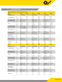
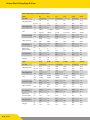
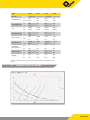
1
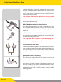
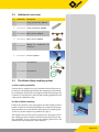
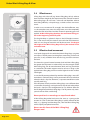
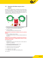
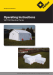
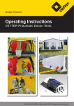
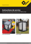
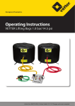
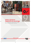
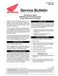
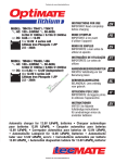
Emergency Pneumatics.
Operating Instructions
VETTER Mini-Lifting Bags 8.0 bar
Article No. 9987015301 | © Vetter GmbH I 03/12 I Changes and errors excepted.
Vetter Mini-Lifting Bags 8.0 bar
Contents
1. Important preliminary remarks. . . . . . . . . . . . . . . . . . . . . . . . . . . . . . . . . . . . 2
2. Description of the product. . . . . . . . . . . . . . . . . . . . . . . . . . . . . . . . . . . . . . . . 2
2.1
Description of the set. . . . . . . . . . . . . . . . . . . . . . . . . . . . . . . . . . . . . . . 2
2.2
Additional accessories. . . . . . . . . . . . . . . . . . . . . . . . . . . . . . . . . . . . . . 4
2.3
The Vetter safety coupling system. . . . . . . . . . . . . . . . . . . . . . . . . . . 4
2.4
Effectiveness . . . . . . . . . . . . . . . . . . . . . . . . . . . . . . . . . . . . . . . . . . . . . . . 5
2.5
Effective load movement. . . . . . . . . . . . . . . . . . . . . . . . . . . . . . . . . . . .5
2.6
Correct handling and usage. . . . . . . . . . . . . . . . . . . . . . . . . . . . . . . . . 6
2.7
Safety instructions. . . . . . . . . . . . . . . . . . . . . . . . . . . . . . . . . . . . . . . . . . 6
3. Preparing the product for use. . . . . . . . . . . . . . . . . . . . . . . . . . . . . . . . . . . . . 7
3.1
Preparations for operation. . . . . . . . . . . . . . . . . . . . . . . . . . . . . . . . . . 7
3.2
Application instructions. . . . . . . . . . . . . . . . . . . . . . . . . . . . . . . . . . . . . 7
4. Operating instructions. . . . . . . . . . . . . . . . . . . . . . . . . . . . . . . . . . . . . . . . . . . . 7
4.1
Operation with compressed air bottles. . . . . . . . . . . . . . . . . . . . . . 7
4.2
Operation with other compressed air supplies. . . . . . . . . . . . . . . 8
4.3
Limit for the period of use. . . . . . . . . . . . . . . . . . . . . . . . . . . . . . . . . . . 9
4.4
Care and storage. . . . . . . . . . . . . . . . . . . . . . . . . . . . . . . . . . . . . . . . . . . .9
5. Trouble-shooting for faults. . . . . . . . . . . . . . . . . . . . . . . . . . . . . . . . . . . . . . . 10
6. Repetitive tests. . . . . . . . . . . . . . . . . . . . . . . . . . . . . . . . . . . . . . . . . . . . . . . . . . 10
7. Technical Data. . . . . . . . . . . . . . . . . . . . . . . . . . . . . . . . . . . . . . . . . . . . . . . . . . . 12
8. Diagrams: Force vs. Stroke. . . . . . . . . . . . . . . . . . . . . . . . . . . . . . . . . . . . . . . . 14
9. List of possible dangers according to EN 12100-1 and EN 12100-2. 16
EC Conformity Declaration. . . . . . . . . . . . . . . . . . . . . . . . . . . . . . . . . . . . . . . . . . 17
Page 1/18
1.
Important preliminary remarks
Only knowledge and the exact observance of this operating manual guarantee correct and reliable operation, achieve the best
possible usage and ensure any claims made within the framework
of the Vetter guarantee.
Only staff are to use Vetter mini-lifting bags who have been instructed in their use by the manufacturer‘s operating manual and
operating instructions.
The operating instructions given here are to be regarded as part
of the product and are to be kept for the complete life duration of
the product. In case the product should be passed on to a successive user then the operating instructions must also be included.
2.
Description of the product
All Vetter Mini-Lifting Bags 8.0 bar are produced by hand in a layer structure and are made of high quality raw material so that a
seamless bag is created as the finished product.
2.1 Description of the set
a. Mini-Lifting Bags
Bag size selection is made according to the task. There are 16 different sizes from 1.1 t to 67.7 tons with a choice of steel cord or
aramide reinforcement. There is no difference in performance between Mini-Lifting Bags having the same size with steelcord and
those with Aramide. Aramide bags are lighter than Lifting bags
made of steel cord (when comparing bags in the same size).
b. Inflation hoses
There are inflation hoses available (5 m and 10 m in length) which
enable the user to control the Mini-Lifting Bags from a safe position. The colours of the hoses, RED and YELLOW, avoid any confusion during control of the different sides (inlets and outlets) of
mini-Lifting Bags.
c. Dual deadman controller 8 bar in plastic housing
Connect the inflation hoses to the outlet coupling on the rear
side of the controller. Connect the air supply to the inlet coupling.
Move the control lever to the front in order to inflate the MiniLifting Bag. In doing this, observe the corresponding manometer
and load.
Release the control lever, thus ending the inflation process, when
the required operating required operating pressure for the lift
power or lift height is reached. The control lever automatically
returns to the center position (zero) when released (deadman
Page 2/18
Vetter Mini-Lifting Bags 8.0 bar
switched). The built-in safety valve automatically activates when
the bag is unintentionally over-inflated above the maximum operating pressure of 8 bar or when there is an increase in pressure of
8 bar or when there is an increase in pressure in the bag due to a
unforeseen loading of the bag.
The activation tolerance for opening and closing of the
safety valve can be +/- 10 %.
Press the control lever in the opposite direction in order to deflate
the bag or to reduce the load.
d. Dual deadman controller 8 bar, aluminium
1
2
Press down the lower button (1) in order to inflate the bag. Inflation is stopped when the button is released and it returns back
to the zero position. The bag is released by pressing the upper
button (2).
e. Single deadman controller 8 bar, aluminium
The single deadman controller, on the left, can be used when only
one Mini-Lifting Bag is to be used.
The single and dual controllers in the 8 bar fitting version do not correspond to the requirements of the Fire
Service standard DIN EN 13 731!
f. Dual controller 8 bar, fitting
Controller with inflation regulator using a ball valve without deadman switching. To empty the bag, open the head of the safety valve (1) by turning to the left. Close the safety valve by turning to
the right after deflation.
g. Single controller 8 bar, fitting
The same version as described in e) but used for the control of
only one Mini-Lifting Bag.
Inventory of items
An inventory and check of all items in the delivery package is to
be made according to the delivery documentation when acceptance of the Mini-Lifting Bag equipment is carried out. A visual
check and function check is also to be made as specified in the
operating manual.
Page 3/18
2.2 Additional accessories
Pos.
Article No.
Description
1
1600 0105 00 Comp. air bottle 10 l / 200 bar
2
1600 0091 00 Comp. air bottle 6 l / 300 bar
3
1600 0084 00 Dual connector 200 bar
4
1600 0091 00 Dual connector 300 bar
5
1600 0120 00
6
1600 0145 00 Pressure regulator
7
1600 0087 00 Hand pump (7)
8
1600 0094 00 Foot pump (8)
Adapter for construction site
compressor
7
8
2.3 The Vetter safety coupling system
a. Inlet coupling controller
Connect the air supply hose, resp. Connection hose of the pressure reducer, to the plug nipple of the inlet coupling on the controller. In doing this, firmly press the nipple into the the coupling until
it latches in. Turn the brass sleeve of the coupling opposite to the
safety pin for additional safety.
b. 8 bar inflation coupling
Firmly press the hose, resp. bag nipple, into the coupling until it
latches in order to connect the inflation hose with the corresponding controller, resp. with the Mini-Lifting Bag. The coupling sleeve must lay on the support ring without any gap (1).
The nipple must be firmly pressed against the spring pressure in
the coupling in order to release the connection (only in pressurefree condition). At the same time, the coupling sleeve must be
pulled back. The connection is then released.
1
Page 4/18
Vetter Mini-Lifting Bags 8.0 bar
2.4 Effectiveness
Lifting bags with side wall (e.g. Vetter Lifting Bag 1.0 bar) achieve
their maximum height by the expansion of the side wall material.
Mini-Lifting Bags do not have a side wall and therefore achieve
their lifting effect by a shape change, i.e. both surfaces curve outwards.
In order to use maximum lift strength, the whole effective area,
i.e. the complete area minus the edge zone, must be completely
under the load to be lifted and the maximum operating pressure
applied. A Mini-Lifting Bag develops the maximum lifting power at the beginning of the lift path!
The bag develops a spherical shape as the lift height increases.
This is the reason why the contact area with the load decreases
until at a max. bag curvature this will be almost zero. The largest
lift height of the Mini-Lifting Bag will only be reached in the
unloaded state.
2.5 Effective load movement
Load path diagram for the individual Mini-Lifting-Bags are given
on request. The lift power (resulting from contacting surface and
pressure) is only available when the first bag curvature contacts
the load.
The lower the space distance between load and Mini-Lifting Bag,
the greater the lift power. In order to fully use the strengths of the
Mini-Lifting Bag, the distance between load and bag should be
at a minimum.The under-support must be at least as large as the
applied Mini-Lifting Bag and must not be higher than the smallest
side length.
In case the lift power produced by one Mini-Lifting Bag is not sufficient then a number of bags can be positioned next to each other
when the load is slip-free. However, a separate controller must be
used for each bag.
If the lift power of only one Mini-Lifting Bag is not sufficient then
a maximum of two bags can be placed on top of each other when
the load is slip-free. This configuration has an additive effect for
the lift height of both Mini-Lifting Bags. The lift power only corresponds to that of the smaller bag!
Never position 3 or more bags on top of each other!
A Mini-Lifting Bag under load reacts the same as a spring under
tension! As soon as the Mini-Lifting Bag is quickly relieved of the
load, e. g. slipping, load breakage etc., then the Mini-Lifting Bag
will be rapidly catapulted outwards!
Never stand in front of the Mini-Lifting Bag!
Danger area!
Page 5/18
2.6 Correct handling and usage
The Mini-Lifting Bag is primarily a pneumatic (normally with air)
rescue device used by the rescue services (e.g. fire services) with
which trapped people can be freed, access gained for rescue and
many other tasks. The Mini-Lifting Bag can also be used as a working device in order to lift or move loads. Mini-Lifting Bags meet
the requirements for fire services as specified in GUV-G 9102. Additional instructions are to be found in the user‘s own operating
instructions.
2.7 Safety instructions
Only prespecified protective clothing is to be worn during operation. The national regulations are to be observed in connection
with lifting bag systems and their use. Mini-Lifting bags must only
be used with compressed air. It is imperative that no inflammable
or aggressively acting gases be used.
Mini-Lifting bags must only be inflated with original Vetter fittings
due to the fact that these have been subjected to an acceptance
test. The lifting bag system is to be inspected before and after
operation to see that it is in a correct and perfect condition.
Never place more than 2 Mini-Lifting Bags
over each other.
Ensure against slippage. Continually prop up loads being lifted
during the lifting procedure. Always ensure that the substructure
material is in a stable condition when constructing the support.
The support must at least cover the
whole bag area and should be larger
in length and width than in height!
Danger of slippage! During support
construction never place metal on metal!
With slippery ground (ice, snow, clay etc.) place stones, branches
similar objects underneath the bag in order to increase ground or
grip. Avoid pointed objects, such as screws, spikes etc. Never place
bags on sharp edges or objects which are hot. Use suitable layers
of lining and cover the complete positioning area of the bag. Protect the bag from sparks coming from welding or cutting work. Do
not subject bags to heavy loads such as hydraulic stamps, winches or falling objects.
Do not stay underneath a load being lifted, never hold or touch the load from underneath !
Remain at a safe distance from the load!
Avoid shearing effects by squeezing the bag during deflation!
Page 6/18
Vetter Mini-Lifting Bags 8.0 bar
Never stand in front of the load but always
at the side of it because under
unfavourable conditions it may swing out!
3.
Preparing the product for use
3.1 Preparations for operation
Remove a set of lifting bags from the vehicle. Ensure sufficient air
supply.
Only perfectly operating and inspected
Mini-Lifting Bag systems are to be used.
The method and type of application is to be decided from case to
case by the operation leader with his own area of responsibility as
well as the operating instructions of the user.
3.2 Application instructions
Move the lifting bag to a suitable position so that at least 75% of
the supporting bag area is under the load. Continually built up
the under-support for maintaining contact when the load is lifted
during the lifting procedure.
Never stand in front of the bag during operation but to the side
of the Mini-Lifting Bag because it could be catapulted outwards
under unfavourable conditions.
3
6
4
Operating instructions
4.1 Operation with compressed air bottles
2
1
5
Page 7/18
4.
Connect the pressure reducer to the compressed air bottle (200 or
300 bar) using the T-Screw (1). Close the valve of the reducer (2).
Open the valve on the bottle (3). The manometer (4) indicates the
pressure in the bottle. Adjust the backpressure to approximately
10 bar using the regulator lever (5) (indication of reduced pressure on the backpressure manometer (6)). Connect air hose of the
pressure reducer to the controller. Open the valve on the pressure
reducer (2).
4.2 Operation with other compressed air supplies
Basically, any air supply which is available can be used for operation of Mini-Lifting Bags as long as the pressure does not exceed
10 bar and the air is free of oil. Amongst others, the set of transition pieces (Art. No.: 1600 0125 01) with the following adapters are
available for operation with other air sources:
8
5
9
3
4 6 7
2
10
1
1. Truck compressed air connection, dual brake system.
For tapping air out of the trailer coupling head.
2. Dummy coupling Seals off the control line of the brake system
Remember! Ensure that the truck does not roll, use brake
blocks!
3. Truck tyre inflation device adapter
For tapping off air from the so-called tyre inflation bottle near
the brake.
Remember! The tyre inflation connection must be ensured by a safety valve as a standard (blow-off pressure approximately 7.5 bar)!
4. Truck tyre valve
Inflation with a normal hand or foot pump as well as other air
supplies for tyre inflation.
5. Truck tyre valve connection, can be clamped For extracting air for the spare tyre.
6. Adapter for the local air pressure network.
7. Adapter Construction-site compressor
8. Air supply hose, 10 m, green.
9. Air supply hose, 10 m, green, with blocking valve.
10. Case, red
Page 8/18
Vetter Mini-Lifting Bags 8.0 bar
4.3 Limit for the period of use
Mini-Lifting Bags are subject, the same as other rubber products,
to natural aging. The first sign of material aging is the loss of flexibility, this is especially seen in the formation of „age cracks“. If
these cracks propagate so far along the upper layer so that the
supporting cord layer (steel or Aramide) is no longer fully insulated then this can quickly limit the tear resistance of the bag wall.
This can cause wall tearing and thus lead of bursting.
The experiences over the past decade have clearly shown that the
failure rate in general for rubber products considerably increases
with application periods exceeding 15 years. Therefore Mini-Lifting Bags should be replaced after 15 to 17 years of use at the
latest. The danger for operational services using over-aged MiniLifting Bags must never be under-estimated, alone due to the
consideration aspect. Although at present there is no regulation
about the time limit for the maximum period of use, the responsibility for this lies wholy and soly with the user, resp. the person
who has been commissioned by him to carry out testing.
4.4 Care and storage
The lifting bag equipment is to be cleaned after each operation.
Cleaning is normally carried out with warm water and a detergent.
Cleaning must never be carried out with
a chemical cleaning agent and never
with high-pressure hot water devices.
Drying is made at normal room temperature.
DIN 7716 is to be observed with long storage periods.
Page 9/18
5.
Trouble-shooting for faults
If the safety valve blows too early because of foreign body penetration caught up inside then the blow-off valve is to be fully
opened on the head of safety valve by turning counter-clockwise
so that the compressed air can escape. If, due to this, the foreign
body is not removed then the upper part of the safety valve is to
be unscrewed when the safety valve is disassembled. To do this,
position the pipe wrench in the centre and unscrew by turning to
the left.
Carefully take out the valve ball and remove foreign body. Firmly
screw on the upper part of the valve again, assemble the safety
valve and check operation. The set pressure must not be changed.
Should the sealing or sealing plate on
the upper part of the valve be removed
then correct operation can no longer
be guaranteed.
The safety valve is to be exchanged.
If operational faults occur on the pressure reducer or controller
due to icing at high air humidity in connection with low temperatures then a normal defrosting agent (the same as in cars) should
be used.
6.
Repetitive tests
Lifting bag systems are to be subjected to repetitive tests according to DIN EN 13731 and national regulations (e.g. GUV-G 9102).
99 Testing on acceptance Testing for completeness by the person/people delegated by
the user.
Visual check and operation test by a trained person according to the operation manual.
99 Visual check and operation test after each application/use by
a trained person.
This test is to be documented.
99 The lifting bag system is to be subjected at least once every
year to a visual check and operation test by a trained person
according to the following check list.
This test is to be documented.
99 The lifting bag system is to be given a pressure test, by user or
manufacturer, according to DIN EN 13 731 and recommendation of the manufacturer, every 5 years or if there is any doubt
about the safety or reliability.
The user is responsible for the correct and professional execution
of the repetitive tests.
Page 10/18
Vetter Mini-Lifting Bags 8.0 bar
Lifting bags or lifting bag systems are not subject to the
requirements specified in EC Guidelines 97/123/EC, Section: 3.15.
Visual check:
A visual check should be made for the following types of damage:
99 Damage caused by separation
99 Damage caused by cuts
99 Damage caused by puncture
99 Damage caused by heat and acids
The bag must be immediately discarded
if, during inspection, established that
there is damage and that the support
cord (steel or ARAMIDE) shows through.
Repair is not possible. Danger of bursting!
Page 11/18
7.
Technical Data
Mini- Lifting Bags steelcord reinforcement
Type
V 10
V 12
V 18
V 20
V 24
V 24 L
Art.-No.
1310000600
1310001000
1310001100
1314002100
1310001200
1310001300
to
9.6
12.0
17.7
19.4
24.0
24.0
US tons
10.6
13.2
19.5
21.4
26.5
26.5
cm
20.3
20.0
27.0
28.0
30.6
20.1
inch
8.0
7.9
10.6
11.0
12.0
7.9
cm
37x37
32x52
47x52
48x58
52x62
31x102
inch
15x15
13x20
19x20
19x23
20x24
12x40
cm
2.5
2.5
2.5
2.5
2.5
2.5
inch
0.98
0.98
0.98
0.98
0.98
0.98
l
9.2
10.7
21.7
24.9
32.9
23.5
cu.ft.
0.3
0.4
0.7
0.9
1.2
0.8
l
82.8
96.3
195.3
224.1
296.1
211.5
cu.ft.
2.9
3.4
6.9
7.9
10.4
7.5
bar
8
8
8
8
8
8
psi
116
116
116
116
116
116
bar
16
16
16
16
16
16
psi
232
232
232
232
232
232
kg
4.5
5.4
7.9
9.1
10.3
10.2
lbs
9.9
11.9
17.4
20.1
22.7
22.5
Type
V 31
V 35 L
V 40
V 48
V 54
V 68
Art.-No.
1310001400
13100008200 1310001500
1310012400
1310001600
1310001700
to
31.4
35.8
39.6
49.3
54.4
67.7
US tons
34.6
39.5
43.7
54.3
60.0
74.6
cm
37.0
31.0
40.2
45.5
47.8
52.0
inch
14.6
12.2
15.8
17.9
18.8
20.5
cm
65x69
43x115
78x69
82x82
86x86
95x95
inch
26x27
17x45
31x27
32x32
34x34
37x37
cm
2.5
2.5
2.5
2.8
2.8
2.8
inch
0.98
0.98
0.98
1.1
1.1
1.1
l
57.5
38.8
75.0
100.0
124.2
161.9
cu.ft.
2.0
1.4
2.6
3.5
4.3
5.7
l
517.5
349.4
675.0
900.0
1,117.8
1,457.1
cu.ft.
18.0
12.3
23.6
31.8
39.5
51.4
bar
8
8
8
8
8
8
psi
116
116
116
116
116
116
bar
16
16
16
16
16
16
psi
232
232
232
232
232
232
kg
14.2
15.1
17.1
21.4
28.4
35.0
lbs
31.3
33.3
37.7
47.2
62.4
77.2
Lift power,max
Lift height, max
Size
Insertion height
Nom. content
Air capacity
Operating
pressure max.
Test pressure
Weight
Lift power,max
Lift height, max
Size
Insertion height
Nom. content
Air capacity
Operating
pressure max.
Test pressure
Weight
Page 12/18
Vetter Mini-Lifting Bags 8.0 bar
Mini- Lifting Bags aramide reinforcement
Type
V1
Art.-No.
1314009300 1314009500 1314018200 1314009600 1314002200 1314002400
V5
V6
V 10
V 12
1.0
3.3
5.7
6.4
9.6
12.0
1.1
3.6
6.3
7.0
10.6
13.2
cm
7.5
12.0
14.5
16.5
20.3
20.0
inch
3.0
4.7
5.7
6.5
8.0
7.9
cm
14x13
25.5x20.0
28x28
29.5x29.5
37x37
32x52
inch
5.5x5.1
10x7.9
11x11
11.6x11.6
15x15
13x20
cm
2.5
2.5
2.5
2.5
2.5
2.5
inch
0.98
0.98
0.98
0.98
0.98
0.98
l
0.30
1.75
3.16
4.4
9.2
10.7
cu.ft.
0.01
0.06
0.11
0.16
0.30
0.40
l
2.7
15.8
28.4
39.6
82.8
96.3
cu.ft.
0.1
0.6
1.0
1.4
2.9
3.4
bar
8
8
8
8
8
8
psi
116
116
116
116
116
116
bar
14
14
14
14
14
14
psi
203
203
203
203
203
203
kg
0.5
1.0
1.4
1.9
3.3
3.9
lbs
1.1
2.2
3.1
4.2
7.3
8.6
Type
V 18
V 20
V 24
V 24 L
V 31
V 35 L
Art.-No.
1314002500 1314003400 1314002600 1314002700 1314002800 1314018300
Lift power,max
Lift height, max
Size
Insertion height
Nom. content
Air capacity
Operating
pressure max.
Test pressure
Weight
Lift power,max
Lift height, max
Size
Insertion height
Nom. content
Air capacity
Operating
pressure max.
Test pressure
Weight
Page 13/18
V3
to
US tons
17.7
19.4
24.0
24.0
31.4
35.8
US tons 19.5
21.4
26.5
26.5
34.6
39.5
cm
27.0
28.0
30.6
20.1
37.0
31.0
inch
10.6
11.0
12.0
7.9
14.6
12.2
cm
47x52
48x58
52x62
31x102
65x69
43x115
inch
19x20
19x23
20x24
12x40
26x27
17x45
cm
2.5
2.5
2.5
2.5
2.5
2.5
inch
0.98
0.98
0.98
0.98
0.98
0.98
l
21.7
24.9
32.9
23.5
57.5
38.8
cu.ft.
0.7
0.9
1.2
0.8
2.0
1.4
l
195.3
224.1
296.1
211.5
517.5
349.4
cu.ft.
6.9
7.9
10.4
7.5
18.0
12.3
bar
8
8
8
8
8
8
psi
116
116
116
116
116
116
bar
14
14
14
14
14
14
psi
203
203
203
203
203
203
kg
5.7
6.2
7.2
6.8
10.1
10.0
lbs
12.6
13.7
15.9
15.0
22.3
22.1
to
Type
V 40
Art.-No.
1314002900 1314028300 1314003000 1314003100
Lift power,max
Lift height, max
Size
Insertion height
Nom. content
Air capacity
Operating
pressure max.
Test pressure
Weight
V 48
V 54
V 68
39.6
49.3
54.4
67.7
US tons 43,7
54.3
60.0
74.6
cm
40.2
45.5
47.8
52.0
inch
15.8
17.7
18.8
20.5
cm
78x69
82x82
86x86
95x95
inch
31x27
32x32
34x34
37x37
cm
2.5
2.8
2.8
2.8
inch
0.98
1.1
1.1
1.1
l
75.0
100.0
124.2
161.9
cu.ft.
2.6
3.5
4.3
5.7
l
675.0
900.0
1,117.8
1,457.1
cu.ft
23.6
31.8
39.5
51.4
bar
8
8
8
8
psi
116
116
116
116
bar
14
14
14
14
psi
203
203
203
203
kg
12.2
14.4
17.3
20.7
lbs
26.9
31.8
38.1
45.6
to
All rights reserved for technical changes within the scope of product improvement.
8.
Diagrams: Force vs. Stroke
Page 14/18
Vetter Mini-Lifting Bags 8.0 bar
Page 15/18
9.
List of possible dangers according to EN 12100-1 and EN 12100-2
Danger
see Page
A.1
Mechanical dangers
1.1
Danger by squeezing
1.7
Danger by puncturing
1.9
Danger by catapulting out
A.2
Danger due to noise
2.1
Injury to hearing
3
2.2
Impairment of speech
3
A.3
Material danger
3.1
Explosion
A.4
Danger due to negligence of ergonomic principles
4.1
Positions which impair health
4
4.2
Negligent use of personal protection devices
3
4.3
Mental over and under demands, stress etc.
3
4.4
Human error
3
4.5
Unfavourable arrangement of visual indications
4
A.5
Unintended movements
5.1
Faults/erroneous functions of the control elements
A.6
Mechanical failure
6.1
Failure of energy supplies
9 / 12
6.2
Failure of the control device
11 / 13
6.3
Loss of stability
A.7
Additional dangers
7.3
due to the control device
8/9
7.5
Movements
8/9
7.8
Negligent use
8/9
7.9
Movement of parts from the stationary position
8/9
7.10
Missing or insufficient visual or acoustic warning devices
8/9
7.11
Insufficient instructions for the user
7.12
Falling loads
7.13
Missing stability
6/7
7.14
Uncontrolled sudden movements
6/7
7.15
Uncontrolled/unintended load movement
6/7
7.16
Insufficient holding devices
3/6
7.17
Insufficient solidity of parts
3/5
7.18
Exceptional conditions during assembly, testing, use, maintenance
3/9
7.19
The effects of loads on persons
3
7.20
Dangers due to negligence of ergonomic principles (load
bumping)
6
7.21
Fire and explosion
7.22
Control failure
3/4/5/6
4
3/4/5/6
3
11
3/5
3
11
3/4
3
Page 16/18
Vetter Mini-Lifting Bags 8.0 bar
EC Conformity Declaration
in accordance with Directive 2006/42/EC
Manufacturer name and address
Vetter GmbH A Unit of IDEX Corporation
Blatzheimer Str. 10 - 12
53909 Zülpich
We hereby declare that the Mini Lifting Bags (Steelcord and Aramide) for lifting and lowering
loads
Type:
______________
Serial-No.: ______________
Model:
______________
(refer to equipment label, to be entered by the customer)
meets the following relevant provisions:
Directive 2006/42/EC on Machinery
Applied harmonised standards, references to which have been published in the Official Journal
of the European Union:
DIN EN ISO 12100
EN 13731
Applied national standards and technical specifications:
Authorised representative for the compilation of technical documents:
Vetter GmbH A Unit of IDEX Corporation
Blatzheimer Str. 10 - 12
53909 Zülpich
This EC Conformity Declaration was issued:
Zülpich, 16.03.12
(Place, Date, Signature)
(Identification of signatory)
Page 17/18
Place your trust in emergency pneumatics!
We are the company who can help you, find a solution to your problem!
Vetter GmbH
A Unit of IDEX Corporation
Sales Germany
International sales
Blatzheimer Str. 10 - 12
D-53909 Zülpich
Germany
Tel.: +49 (0) 22 52 / 30 08-50
Fax: +49 (0) 22 52 / 30 08-70
Mail: [email protected]
Tel.: +49 (0) 22 52 / 30 08-60
Fax: +49 (0) 22 52 / 30 08-71
Mail: [email protected]
www.vetter.de
Article No. 9987015301 | © Vetter GmbH I 03/12 I Changes and errors excepted. I Made in Germany