1
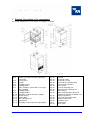
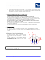
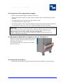
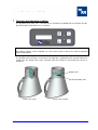
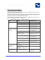
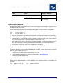
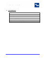
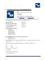
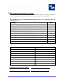
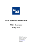
Operating Instructions
Cartmaster IFA
TEKA Absaug- und Entsorgungstechnologie GmbH
Industriestraße 13 D-46342 Velen
Postfach 1137 D-46334 Velen
Tel.: +49 (0) 2863 9282-0
Fax: +49 (0) 2863 9282-72
E-Mail: [email protected]
www.teka.eu
Contents
1
Drawing/ Description of the components
3
2
Preface
4
3
Intended use of the TEKA – CARTMASTER - IFA
5
4
Safety instructions
5
5
Storage, transport and setting-up of the device
7
6
Commissioning
7
6.1
Mounting of the collecting elements
1
6.2
Connection of the compressed-air supply
8
6.3
Mounting the baffle plate for exhaust air (only for Cartmaster-1)
8
6.4
Connection of the device
8
7
Operation and operating condition
9
8
Maintenance
10
8.1
Cleaning of the filter cartridge
11
8.2
Compressed air supply
11
8.3
Emptying of the dust collecting tray
12
8.4
Discharge of condensation water
13
8.5
Changing of the filter cartridge
13
8.6
Precoating new filter cartridges
15
8.7
Emptying of the compressed air tank
15
9
Fault removal and fault diagnosis
16
10
Dismantling/disposal
17
11
List of spare parts
18
12
Technical data
19
13
Declaration of conformity for TEKA-CARTMASTER- IFA
20
14
Briefing protocol for users of the device
21
BA_Cartmaster-PF1-PF-2_IFA_GB
-2-
15.08.2013
1
Drawing/ Description of the components
The version Cartmaster 2 – IFA (2 arms, 2 cartridges) is shown.
Pos.1
Pos.2
Pos.3
Pos.4
Pos.5
Pos.6
Pos.7
Pos.8
Pos.9
Pos.10
Pos.11
Pos.12
Pos.13
Pos.14
Pos.15
Membrane keyboard
Suction arms with extractor cowl or pipe
connection
Casing cover
Handle
Cartridge casing
Cartridge door
Filter cartridges (for unit with 1 arm only 1
filter cartridge)
Cartridge guide
Cartridge holder
Clamping screw for the filter cartridge
Drawer casing
Drawer door
Dust collecting tray
Lifting device
Clamping screw for the dust collecting bin
BA_Cartmaster-PF1-PF-2_IFA_GB
-3-
Pos.16
Pos.17
Pos.18
Pos.19
Pos.20
Pos.21
Pos.22
Pos.23
Pos.24
Pos.25
Pos.26
Pos.27
Pos.28
Pos.29
Pos.30
Pos.31
Pos.32
Fan casing
Fan door
Pneumatics door
Pneumatics casing
Cap nut for the cartridge door
Swivel castor with brake
Swivel castor
Screw for attaching arm
Split washer for attaching arm
Rotary flange
Power cord with power plug and
indicator for direction of rotation: red
End piece grommet
Cap nut for pneumatics door
Compressed air tank
Discharge valve
Signal hooter
Check valve
15.08.2013
2
Preface
Congratulations on your purchase of the filter unit of the TEKA-Cartmaster series!
Our engineers ensure through continuous development that our filter systems correspond with the
latest state-of–the-art. Nevertheless misapplication or malfunction can lead to risks for your safety.
Therefore, please note the following for a successful use of the filter system:
Read these instructions before using the system and follow the safety instructions to
avoid injuries!
Non-intended use of the system may lead to severe injury or death!
Save this manual carefully! Consider this manual to be part of the product!
Note all instructions on the product!
Note the local regulations at the installation location!
Refer to the manufacturer's specifications. If you have any doubts, please contact the
manufacturer:
Tel.:
+49 28 63 - 92 82 - 0
Fax:
+49 28 63 - 92 82 – 72
We wish to thank you for your confidence and wish you great success!
BA_Cartmaster-PF1-PF-2_IFA_GB
-4-
15.08.2013
3
Intended use of the TEKA – CARTMASTER - IFA
The filter unit is mainly used to extract and filter dust and fumes. The filter unit is suitable for the
separation of welding fumes of steels with an alloying of for example nickel and chrome of 30% that
are produced during the processing of steels and thus fulfils the highest welding fume class “W3”
according to DIN EN ISO 15012-1.
Improper use of the device can damage parts of it and be a danger to life and limb!
The device must not be used for the extraction of oil-laden welding fume, explosive dust
and gases, hybrid mixtures, glowing or burning substances, gases, water, etc. The device
must not be operated in explosive zones. (If you have any doubts, please contact the
manufacturer!)
The polluted air is captured by the extractor cowl (or the capture element) and gets through the
suction arm (or the suction hose) into the filter unit. Here, the particles are collected on the surface
of the integral filter cartridge. The cleaned air is sucked by the fan and returned into the working
space via the exhaust grid on the back side.
Please note:
The degree of saturation of the filter cartridge (pos. 7) is monitored electronically. In order to maintain the suction capacity of the unit, the filter cartridge is cleaned automatically once a preset value
is reached.
Via the integral pneumatic cleaning the compressed air is homogeneously dispersed on the filter
surface which eliminates the filter cake. (see chapter 8.1: “Cleaning of the filter cartridge”)
The disrupted dust is collected in a dust collecting tray and can be disposed from there. (see chapter 8.3: “Emptying of the dust collecting tray”)
4
Safety instructions
The machine is designed according to the state of the art and the recognised safety regulations.
Nevertheless, its use may create dangers to life and limb of the user or third parties or impairments
of the machine or other tangible assets. Therefore, read and follow the safety instructions before
using the product.
The operator must make sure that personnel authorized by him is familiar with all the safety instructions of this manual. The operator must ensure that all types of work on the machine are only carried out by authorized and qualified personnel. For that purpose we recommend to use the briefing
protocol on the final page.
•
Read and follow these instructions before using the device!
•
Keep these operating and maintenance instructions carefully!
•
Do not use the device to exhaust highly flammable or explosive gases!
•
Do not use the device in explosive zones, as for example zone 0, zone 1, zone 2, zone 20,
zone 21, zone 22!
•
Do not use the device to exhaust burning or glowing materials, as for example cigarettes,
matches, metallic dust or chips, paper, cleaning wipes, etc.!
•
Do not use the device to exhaust burning or ignitable materials, as for example oil or oil mist,
greases, separating agents (e.g. silicone spray), detergents, etc.!
•
Do not use the device to exhaust aggressive materials!
•
Do not use the device to exhaust liquids of any kind!
BA_Cartmaster-PF1-PF-2_IFA_GB
-5-
15.08.2013
•
Do not use the device to exhaust organic materials without the written approval of the manufacturer!
•
Depending on the setting of the control, there can be an automatic postcleaning of the filter
cartridges when the device is switched off. To avoid the dust escaping from the extractor cowl
of the suction arm, the throttle valve of the extractor cowl must always be closed once the device is switched off (see therefore the indications of the chapter “Operation and operating condition”).
•
In case of fire use an approved fire extinguisher.
•
Protect the connecting plug and the mains lead against heat, moisture, oil and sharp edges!
•
Mind the admissible supply voltage! (Refer to the type plate!)
•
Use only original TEKA spare parts!
•
Do not use the device without a filter!
•
Before opening the device disconnect the filter unit from the main power supply!
•
Before starting any repair or maintenance work, empty the compressed air tank (see chapter
8.7: “Emptying of the compressed air tank”).
•
The exhaust opening must not be obstructed or covered!
•
Always make sure that the device stands firmly and that the brakes on the swivel castors are
put on!
•
Disconnect the filter unit from the main power supply in case of cleaning or maintaining the
device or changing of component parts!
•
Dispose of the filter element in accordance with legal requirements!
•
The mains cable of the device must be checked regularly for signs of damage!
•
The device must not be used if the condition of the mains cable is not faultless!
•
Use only dry and oil-free compressed air and an operating pressure of min. 3 bar and max. 4
bar.
•
The extractor cowl must follow the weld seam, if possible by using the movement of the welding fume caused by thermal influences. Connections between the workpiece and the extractor
cowl (and in general between the workpiece and the filter unit) must be avoided, so that the
welding current cannot flow back to the welding machine through the protective conductor of
the filter unit.
•
The maximum permitted distance to the welding point must not exceed 25 cm.
•
Do not use the filter unit if any components are defective, missing or damaged. In any of these
cases please contact the TEKA service department by calling 0 28 63 / 92 82 - 0.
BA_Cartmaster-PF1-PF-2_IFA_GB
-6-
15.08.2013
•
5
During suction of carcinogenic welding smoke as for example from nickel or chrome containing materials the ventilation requirements of the TRGS 560 “Air recirculation in connection with
the treatment of carcinogenic hazardous materials” must be met!
Storage, transport and setting-up of the device
Falling or unmounted parts of the device may create danger to life and limb.
The device must be secured against tilting and slipping when it is stored or transported. Do not
stand under or next to the floating load. Direct all people out of the danger area. Lift trucks, forklift
trucks and transport cranes must have a sufficient minimum load bearing capacity.
The device must be set up on a suitable underground. Otherwise falling or functional impairment may create danger to life and limb.
The underground must be horizontal and free from vibration. The operator must check the bearing
capacity of the underground.
The device must be stored in a dry place and protected against moisture during transport.
6
Commissioning
The filter unit is, with the exception of the collecting element, delivered completely assembled.
The collecting element, e.g. the suction arm, must be assembled to the device before the commissioning.
6.1 Mounting of the collecting elements
The collecting element, e.g. the suction arm or suction
hose, must be fixed to the intake nozzle or the casing
cover.
If using a suction arm it is attached with the help of the
supplied rotary flange (pos. 25), the screws (pos. 23) and
the split washers (pos. 24).
Please note:
Be sure that the nozzle is rotatable now!
BA_Cartmaster-PF1-PF-2_IFA_GB
-7-
15.08.2013
6.2 Connection of the compressed-air supply
•
External supply only with approved compressed-air hose!
•
Connect the compressed-air hose to the end piece grommet (pos. 27) with the help of a hose
coupling.
•
The operating pressure must be of min. 3 bar and max. 4 bar.
•
Use only dry and oil-free compressed air.
•
The external compressed-air supply must allow the compressed air tank to reach the operating
pressure within the valve pause time (see separate operating manual of the control).
Please note:
Before starting any repair or maintenance work, empty the compressed air tank and disconnect
the filter unit from the main power supply and secure it against being switched on again.
If the pneumatic system is leaky, the filter unit must not be operated.
Without a compressed air supply, the filter cartridge gets polluted very quickly and the unit
switches to disturbance (filter alarm)!
6.3 Mounting the baffle plate for exhaust air (only for Cartmaster-1)
Before the commissioning, the supplied baffle plate for
exhaust air must be mounted. Therefore hang up the
baffle plate for exhaust air.
(The Cartmaster with 2 arms does not need a baffle
plate for exhaust air)
6.4 Connection of the device
•
Connect the filter unit to the main power supply. (Refer to the indications on the type plate!)
BA_Cartmaster-PF1-PF-2_IFA_GB
-8-
15.08.2013
7
Operation and operating condition
The operation of the filter unit is carried out on its membrane keyboard with an electronic text display. All functions of the device are set up on it.
Please note:
For program settings, menu navigation, etc. of the device please refer to the enclosed operating
manual “ControlUnit”.
According to the settings of the control “ControlUnit” there can be automatic postcleanings of the filter cartridges when the device is turned off. To avoid dust escaping from the extractor cowl of the
suction arm, the throttle valve of the extractor cowl must always be closed when the device is
turned off.
throttle valve
handle for throttle valve
throttle valve OPEN
BA_Cartmaster-PF1-PF-2_IFA_GB
throttle valve CLOSED
-9-
15.08.2013
8
Maintenance
Through filtration of the dust particles, the saturation of the filter cartridge rises and the suction performance is reduced.
The saturation of the filter cartridge (pos. 7) is electronically monitored. To keep the admissible
suction capacity of the device, the filter cartridge is automatically cleaned when the default value is
reached. (see chapter 8.1: “Cleaning of the filter cartridge”)
The dust particles are blown from the inside to the outside on the side of the purified gas. The detached filter cake falls into the dedicated dust collecting tray (pos. 13). (see chapter 8.3: “Emptying
of the dust collecting tray”). The service life of the filter cartridge depends very strongly on the operating conditions and can therefore not be predicted.
If despite cleanings the filter unit permanently shows “filter alarm” at the display and the signal
hooter (pos. 31) rings, the filter cartridge must be replaced. (see chapter 8.5:”Changing of the filter
cartridge”)
Please note:
The operation of the filter unit must be stopped during the changing of the filter cartridge.
For all repair or maintenance work it must be ensured that the device will not start a sudden filter
cleaning process. Therefore before starting any repair or maintenance work, disconnect the device from the main power supply and from the compressed air system. Also empty the compressed air tank as it can be under pressure even without compressed air supply. (see chapter
8.7:”Emptying of the compressed air tank”)
The changing of the filter cartridge and the disposal must only be carried out in well-ventilated
rooms and while wearing an appropriate respiratory mask! The same applies to the emptying of
the dust collecting tray. We recommend: respiratory protection half mask DIN EN 141/143 protection level P3. Wearing appropriate protective gloves is recommended as well.
Dispose of the filter according to legal regulations! The polluted filter elements must be packed into an appropriate container (e.g. PE bag). Bags are optionally available (see spare parts list)! We
recommend having PE bags in stock.
All maintenance work must be carried out by authorised and qualified personnel!
A re-start-up of the device may only be carried out if it is ensured that the filter unit corresponds in
its functions to the original state. Repairs must only be carried out by employees of TEKA or staff
authorized by the operator after consultation with TEKA-GmbH.
The operator is in accordance to national regulations obliged to carry out replications and functional tests. Otherwise malfunctions of the device can lead to dangers. If not defined by other national regulations, we recommend tests of the electric and pneumatic pipes every 6 months. If the
pneumatic pipe is leaky, the filter unit must not be operated anymore.
Furthermore, we recommend monthly visual inspections and functional tests of the device. This
includes the control of all movable parts such as doors and the fan to check if they work well and
frictionless.
BA_Cartmaster-PF1-PF-2_IFA_GB
- 10 -
15.08.2013
8.1 Cleaning of the filter cartridge
The saturation of the filter cartridge (pos. 7) is electronically monitored. To keep the admissible
suction capacity of the device, the filter cartridge is automatically cleaned when the default differential pressure value is reached. If after the cleaning of the filter cartridge the default differential pressure value is still not undercut, a new cleaning starts.
If the maximal admissible filter resistance is reached, the filter unit shows “filter alarm”. If despite
the automatic cleaning of the filter cartridge the alarm value can not be undercut, the filter cartridge
must be replaced. (see chapter 8.5: ”Changing of the filter cartridge”).
The differential pressure values in the control that initiate a cleaning or a filter alarm are default
values that are adapted to the filter unit or the filter cartridges. For detailed information about the
mode of operation of the control, please refer to the separated operating manual “ControlUnit”.
During the automatic cleaning the filter unit stays in service.
The service life of the filter cartridge depends very strongly on the operating conditions and can
therefore not be predicted.
Please note:
The manual beating out and washing out leads to the destruction of the filter medium and is not
allowed as the pollutants get into the indoor air!
Depending on the setting of the control, there can be an automatic postcleaning of the filter cartridges when the device is switched off. To avoid the dust escaping from the extractor cowl of the
suction arm, the throttle valve of the extractor cowl must always be closed once the device is
switched off (follow the indications of the chapter “Operation and operating condition”).
8.2 Compressed air supply
To ensure a troublefree operation of the device, there must be a defect-free compressed air supply.
•
Use only dry and oil-free compressed air.
•
The condensation water produced in the compressed air tank (pos. 29) must be emptied regularly. (see chapter 8.4: ”Discharge of the condensation water”)
•
If an upstream water separator is used (optionally available), it must be controlled and, if necessary, emptied regularly.
•
The pneumatic parts of the device must be regularly checked for tightness.
•
Use the external compressed air supply with an admissible compressed air pipe and an operating pressure of min. 3 bar and max. 4 bar.
•
In the pneumatics casing is a compressed air tank with a volume of 15 l serving as a reserve.
The content is sufficient for one cleaning procedure. After the cleaning procedure compressed
air for the next cleaning interval streams in. The check valve (pos. 32) ensures that the compressed air stays inside the compressed air tank even in case of interruption of the compressed
air supply.
Please note:
Before starting any repair or maintenance work, empty the compressed air tank and disconnect
the filter unit from the main power supply. (see chapter 8.7:”Emptying of the compressed air
tank”).
If the pneumatic system is leaky, the filter unit must not be operated.
Without a compressed air supply, the filter cartridges gets polluted very quickly and the unit
switches to disturbance (filter alarm)!
BA_Cartmaster-PF1-PF-2_IFA_GB
- 11 -
15.08.2013
8.3 Emptying of the dust collecting tray
The dust collecting tray (pos. 13) must be cleaned regularly. The interval depends on the produced
amount of dust, but it must be emptied at least once a week. The dust collecting tray may only be
filled to 25% maximal! (If you have any doubts, please contact the manufacturer!)
Please note:
The filter cartridge must be cleaned before the emptying of the dust collecting tray. The cleaning is
carried out with menu item 3 of the control „Manual start of cleaning“. The procedure is described in
the supplied operating manual “ControlUnit”! The cleaning must be carried out 3 times. Please wait
for 5 minutes after the cleaning of the filter cartridge before opening the drawer door (pos. 12).
•
Switch off the filter unit on the touch-sensitive membrane keyboard
•
Disconnect the filter unit from the main power supply.
.
•
The compressed air tank must be emptied before starting any maintenance work. (see chapter
8.7: “Emptying of the compressed air tank”)
•
Before emptying the dust collecting tray hold ready an appropriate container (e.g. PE bag or
plastic sack) for disposal.
Please note:
Bags are optionally available (see spare parts list)! We recommend having PE bags in stock.
•
Open the drawer door (pos. 12).
•
Turn low the lifting device (pos. 14) with the help of the clamping screw (pos. 15).
•
Pull out the dust collecting tray (pos. 13).
•
Take out the dust collecting bag with the collected dust. Close it with a cable tie or something
similar before taking it out.
•
Store and dispose of the dust collecting bag with the dust in an appropriate bag according to legal requirements.
•
Put a new plastic bag into the dust collecting tray in a way that the opening of the bag is slipped
over the edge of the dust collecting tray.
•
Push the dust collecting tray (pos. 13) to the limit stop into the drawer casing (pos. 11).
•
Turn up the lifting device (pos. 14) with the help of the clamping screw (pos. 15) in a way that
the dust collecting tray (pos. 13) seals tightly. (Check the seal under the cartridge casing (pos.
5) for damages.)
•
Close the drawer door (pos. 12).
•
Connect the filter unit to the main power supply. (Refer to the type plate!)
•
Switch on the filter unit on the touch-sensitive membrane keyboard
.
Please note:
The emptying of the dust collecting tray may only be carried out in well-ventilated rooms and
while wearing an appropriate respiratory mask!
Before starting any repair or maintenance work, empty the compressed air tank.
We recommend: respiratory protection half mask DIN EN 141/143 protection level P3.
BA_Cartmaster-PF1-PF-2_IFA_GB
- 12 -
15.08.2013
The operations mentioned above must only be carried out by trained employees.
Dispose of the dust according to legal requirements!
8.4 Discharge of condensation water
The condensation water produced in the compressed air tank (pos. 29) must be emptied regularly
as followed:
•
Switch off the filter unit on the touch-sensitive membrane keyboard
•
Disconnect the filter unit from the main power supply.
.
•
Disconnect the filter unit from the external compressed air supply.
•
Open the discharge valve (pos. 30) and fill the condensation water in an appropriate container.
(By opening the discharge valve, the compressed air in the compressed air tank (pos. 29) escapes.)
Store and dispose of the condensation water in an appropriate container according to legal requirements.
•
•
Close the discharge valve (pos. 30).
•
Connect the filter unit to the external compressed air supply.
•
Connect the filter unit to the main power supply. (Refer to the type plate!)
•
Switch on the filter unit on the touch-sensitive membrane keyboard
.
Please note:
The operations mentioned above must only be carried out by trained employees!
Dispose of the condensation water according to legal requirements!
8.5 Changing of the filter cartridge
If the maximum admissible filter resistance is reached, the filter unit shows “filter alarm”. If despite
the automatic cleaning of the filter cartridge the alarm value can not be undercut, the filter cartridge
must be replaced. (see chapter 8.5: ”Changing of the filter cartridge”).
The differential pressure values in the control that initiate a cleaning or a filter alarm are default
values that are adapted to the filter unit or the filter cartridges. For detailed information about the
mode of operation of the control, please refer to the separate operating manual “ControlUnit”.
Please note:
The filter cartridge must be cleaned before being changed. The cleaning is carried out as a manual
cleaning with the help of the control. The procedure is described in the supplied operating manual
“ControlUnit”! The cleaning must be carried out 3 times.
Please wait for 5 minutes after the cleaning of the filter cartridge before opening the drawer door
(pos. 12).
•
Switch off the filter unit on the touch-sensitive membrane keyboard
•
The changing of the filter cartridge must be carried out by two people.
•
Disconnect the filter unit from the main power supply.
BA_Cartmaster-PF1-PF-2_IFA_GB
- 13 -
.
15.08.2013
•
Before starting any maintenance work empty the compressed air tank. (see chapter 8.7:
“Emptying of the compressed air tank”)
•
Disconnect the filter unit from the external compressed air supply.
•
Before changing the filter cartridges hold ready an appropriate container (e.g. PE bag or
plastic sack) for disposal.
Please note:
The polluted filter cartridges must be packed into an appropriate container (e.g. PE bag). Bags are
optionally available (see spare parts list)! We recommend having PE bags in stock.
•
Empty the compressed air tank (pos. 29) by opening the discharge valve (pos. 30). (By
opening the discharge valve, some condensation water can leak out.)
•
Resolve the cap nuts (pos. 20) and open the cartridge door (pos. 6).
•
Resolve the clamping screw (pos. 10) of the cartridge holder (pos. 9) and slip the disposal
bag over the cartridge holder and the filter cartridge.
•
Hook off the cartridge holder (pos. 9) and take it out of the device together with the filter cartridge (pos. 7) and the disposal bag.
•
Resolve the cylinder nut outside on the cartridge’s bottom and take the displacer out of the
filter cartridge without generating dust. Therefore do not touch the cylinder nut directly with
your hands, but grab it from the outside through the bag.
•
Pull the cartridge holder out of the disposal bag past the filter cartridge without generating
dust.
•
Put the displacer into the new filter cartridge in way that the screw of the displacer is put
through the whole of the cartridge’s bottom. Fasten the displayer with the cylinder screw
from the outside.
Please note:
Use only TEKA replacing filters!
•
Push the new filter cartridge with the displacer into the cartridge guide (pos. 8) of the device
and hang it up with the cartridge holder.
•
Fasten the clamping screw (pos. 10) of the cartridge holder (pos. 9).
•
Close the cartridge door (pos. 6) and fasten the cap nuts (pos. 20).
•
Connect the filter unit to the external compressed air supply.
•
Connect the filter unit to the main power supply. (Refer to the type plate!)
•
For a longer service life of the new filter cartridges we recommend to precoat them before
the first commissioning. (see chapter 8.6: “Precoating the new filter cartridges”)
•
Switch on the filter unit on the touch-sensitive membrane keyboard
.
Please note:
The changing of the filter cartridge and the disposal must only be carried out in well-ventilated
rooms and while wearing an appropriate respiratory mask!
Before starting any repair or maintenance work, empty the compressed air tank.
We recommend: respiratory protection half mask DIN EN 141/143 protection level P3.
The operations mentioned above must only be carried out by trained employees.
Dispose of the filter according to legal requirements!
BA_Cartmaster-PF1-PF-2_IFA_GB
- 14 -
15.08.2013
8.6 Precoating new filter cartridges
We recommend to pre-treat new filter cartridges with filter aid before the first commissioning. The
filter aid acts against a caking of the exhausted particles on the filter surface and extends the service life of the filter cartridges.
Wir empfehlen,
Contact with the filter aid can be a danger to the respiratory tracts, cutaneous irritations or irritations of the eyes. Refer to the manufacturers indications listed here:
Handling:
Avoid dust formation!
Storage:
Respiratory protection:
Hand protection:
Eye protection:
Body protection:
Close the container firmly before storing it!
Fine dust respirator without protection stage!
Protective gloves of fabric, rubber or leather!
Safety glasses with side protection!
Working footwear antistatic!
Unlike the other maintenance work, this step must be carried out while the device is in service and
turned on so that the precoat can reach the filter cartridges though the suction.
There must not be any compressed air in the compressed air tank and the
compressed-air hose must be disconnected from the device. (see chapter 8.7:”Emptying of the
compressed air tank”)
Switch on the device. The precoat (10g for one square meter filter surface) must be entered via the
collecting point.
8.7 Emptying of the compressed air tank
Before starting any repair or maintenance work, empty the compressed air tank as followed:
•
Disconnect the filter unit from the main power supply.
•
Disconnect the filter unit from the external compressed air supply.
•
Open the discharge valve (pos. 30) and fill the condensation water in an appropriate container.
(By opening the discharge valve, the compressed air in the compressed air tank (pos. 29) escapes.)
•
Store and dispose of the condensation water in an appropriate container according to legal requirements.
Only after finishing all repair and maintenance work reconnect the compressed air tank as followed:
•
Close the discharge valve (pos. 30).
•
Connect the filter unit to the external compressed air supply.
•
Connect the filter unit to the main power supply. (Refer to the type plate!)
Please note:
The operations mentioned above may only be carried out by trained employees!
BA_Cartmaster-PF1-PF-2_IFA_GB
- 15 -
15.08.2013
9
Fault removal and fault diagnosis
In the presented table you can find a list of faults of the device. Fault indications of the control are
explained in the separate operating manual.
A re-start of the device may only be carried out if it is ensured that the filter unit corresponds in its
functions to the original state. Repairs may only be carried out by employees of TEKA or staff authorized by the operator after consultation with TEKA-GmbH.
For all repair work refer to the chapters “Safety instructions“ and “Maintenance“. If you have any
doubts, please contact the TEKA service department:
Tel.:
0 28 63 - 92 82 - 0 Fax:
0 28 63 - 92 82 - 72
Fault
Cause
Elimination of defect
No suction capacity
(fumes are not sucked
off).
Suction hose is not connected.
Connect the suction hose.
Suction hose is damaged.
Replace the suction hose.
Suction trajectory is clogged.
Check the suction trajectory
and eliminate the defect.
Cleaned air outlet is covered.
Check the cleaned air outlet
and eliminate the defect.
Filter element saturated.
Replace the filter pack, dispose of the old filter according
to the requirements!
Damage at the suction hose.
Replace the suction hose.
Suction hose or suction arm not
correctly connected.
Check the connection of the
suction hose or suction arm
and connect it.
Motor turns into wrong direction.
Change the rotating field of the
mains tapping point.
Cleaned air outlet is narrowed.
Check the cleaned air outlet
and eliminate the defect.
Suction trajectory is narrowed.
Check the suction trajectory
and eliminate the defect.
Throttle valve of the extractor cowl
is closed.
Open the throttle valve.
Suction capacity too
low (fumes are hardly
sucked off).
Dust outlet at the cartridge door.
Dust outlet at the suction intake of the suction arm.
BA_Cartmaster-PF1-PF-2_IFA_GB
One or several of the door handles Close the door handles.
are not closed.
The seal between the cartridge
The seal must be renewed.
door and the cartridge casing is
damaged.
The automatic postcleaning of the
filter cartridge is activated.
- 16 -
Close the throttle valve of the
extractor cowl when the device
is switched off.
15.08.2013
Fault
Cause
Elimination of defect
Device does not start.
Connector power supply is not or
wrongly plugged.
Check/plug the connector
power supply.
No power on socket.
Check the power line and eliminate the defect.
10 Dismantling/disposal
The dismantling of the device may only be carried out by employees of TEKA or by employees who
are authorized by the operator.
For all dismantling work refer to the indications in the chapter “Safety instructions” and “Maintenance”. If you have any doubts, please contact the TEKA service department:
Tel.:
0 28 63 - 92 82 - 0
Fax:
0 28 63 - 92 82 - 72
•
Only trained electricians are allowed to carry out the dismantling of the device, the electrical installation or the power supply.
•
Before starting the dismantling of the device, disconnect it from the main power supply and from
the external compressed air supply and empty the compressed air tank.
•
While working on the device appropriate respiratory protection and protective clothing must be
worn. We recommend respiratory protection half mask DIN EN 141/143 protection level P3.
•
The pollutants and the filter elements must be disposed of properly.
•
Follow the instructions of the manufacturer or contact the manufacturer.
To provide for proper operation of the CARTMASTER as well as a proper disposal of the extracted
dust, we offer the following services:
•
•
Assistance in searching a disposal contractor in your area.
A list of all disposal companies in Germany can be found on www.bde-berlin.de.
•
A maintenance and repair contract
•
Customer advisory service by telephone
Do not hesitate to talk about these services with our service department which is available for you
24 hours.
Tel.:
0 28 63 / 92 82 - 0
BA_Cartmaster-PF1-PF-2_IFA_GB
Fax:
0 28 63 / 92 82 72
- 17 -
15.08.2013
11
List of spare parts
Designation:
Item number:
Filter cartridge 7,8m²
10025078
Filter cartridge 10m²
10025
Star filter cartridge, type easy clean + 12,5m²
100050125
PE bag to dispose of filter cartridges (4 bags)
10030251702
PE bag to put into dust collecting tray (10 bags)
10030250
BA_Cartmaster-PF1-PF-2_IFA_GB
- 18 -
15.08.2013
12 Technical data
Filter unit
TEKA – CARTMASTER - IFA
Type
Cartmaster – 1 arm
Cartmaster - 2 arms
Supply voltage
V
400
Frequency
Hz
50
Current type
Ph
3
Engine performance
kW
1,5
2,2 / 3,0
Max. volumetric flow rate
m³/h
1145
1900
Min. volumetric flow rate
m³/h
700
1160
Pa
2000
2000
Max. diminished pressure
Protection class
IP 54
ISO - class
F
Control voltage
V
230
On-period
%
100
Width x Depth x Height
Weight
mm
665 x 1100 x 1270
665 x 1100 x 1630
kg
160
190 / 200
Type of filter
1 or 2 filter cartridges
Filter surface of the filter cartridge
m²
Removal rate
%
7,8 / 10 / 12,5
>99
Mode of cleaning
Noise level (Measured acc. to DIN 45635 T1 in 1m
distance from the surface of the unit in a clear area at the
maximum volumetric flow rate.)
Ambient temperature
pulse-jet
dB(A)
ca. 74
°C
+5 to +35
Compressed air
External
Compressed air supply
BA_Cartmaster-PF1-PF-2_IFA_GB
15,6 / 20 / 25
dry / oil-free
- 19 -
15.08.2013
13 Declaration of conformity for TEKA-CARTMASTER- IFA
TEKA
Absaug - und Entsorgungstechnologie GmbH
Industriestraße 13
D - 46342 Velen
Tel.:+49 2863 92820
Fax:+49 2863 928272
e-Mail: [email protected] Internet: http://www.teka.eu
We hereby declare under our sole responsibility that the product mentioned above from the machine
no.: 9000010011001 on fulfils the requirements of the following directives:
Machinery Directive:
2006/42/EG
Electromagnetic Compatibility:
2004/108/EG
Pressure Equipment Directive:
97/23/EG
Low Voltage Directive:
2006/95/EG
Applied harmonized standards:
DIN EN 349
DIN EN ISO 4414
DIN EN 12100
DIN EN 60204 part 1
DIN EN ISO 13857
DIN EN ISO 626 part 1
Where applicable other national standards and specifications:
DIN 45635 part 1
-
DIN EN ISO 15012-1
This declaration becomes invalid if the extraction and filter unit is modified without the manufacturer’s
written consent.
Responsible for technical documentation: TEKA GmbH, Technical Department, D-46342 Velen
(Jürgen Kemper, general manager)
Velen, 29 December 2012
BA_Cartmaster-PF1-PF-2_IFA_GB
- 20 -
15.08.2013
14 Briefing protocol for users of the device
(This form can be used by the operator to document the briefing of his employees. Briefings should only be
carried out by authorized employees. Refer to the indications in the chapter “Safety instructions”).
By signing the form, the briefed employee confirms that he has been briefed in the
following points:
Briefing
done
Description of the filter unit
Operating method and fields of application of the filter unit
Explanation of the safety instructions
Methods of operation in case of fire
Explanation of the control of the filter unit
Maintenance, change and cleaning of the filter element
Maintenance of the compressed air supply
Emptying of the dust collecting tray
Correct disposal
Name of the employee (legible)
Briefing was carried out by (legible):
Signature:
BA_Cartmaster-PF1-PF-2_IFA_GB
Signature
___________________________
______________
- 21 -
_.
15.08.2013