1
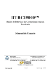
18020074, Rev. A 11/2003
ÒÐ2000
Transmitter
Distributor:
Installation
BASA
Bulgarian
Alarm Systems
Association
32
1
Manual
This manual is intended for authorized personnel installing TP2000 transmitters on
perimeters. It does not refer to the end user of the unit.
2
31
TABLE OF CONTENTS
30
INTRODUCTION
4
GENERAL DESCRIPTION OF TP2000 V.6.X TRANSMITTER
4
Calculating the Length of the TP2000 Transmitter Antenna
According to Transmission Frequency
Installing TP2000 Transmitter
6
6
INTRODUCTION TO TP2000 INTEGRATOR
7
Transmitter Programming Procedures
8
MAIN SCREEN OF PROGRAMMING KIT FOR TP2000V.6.X
TRANSMITTERS
9
Bar Menu
Radio Tab
Frequency Group
Identification Group
Radio Control Group
Advanced Properties Screen
Inputs Tab
Test Mode Tab
COM Tab
Status Bar
Value Verification
10
12
13
13
14
16
20
23
26
27
27
INDEX
28
3
Introduction
Thank you for purchasing TP 2000 v. 6.X transmitter. This new version features the following additions and improvements:
• it allows for an independent distribution of events between two transmission frequencies and a specification of a high-priority channel
• fully programmable without jumpers, programmed by means of a Windows® based application with intuitive user-friendly interface
O
ODD, 12
P
Parity, 12
Power On, 16
• supports a choice of three protocols at the same time — Electronics
Line, LARS and LARS1
• superbly reliable performance within a temperature range of - 40° C to +
60° C
• compact design.
R
RadioControl, 11
Random Time, 13
Round Count on Freq 1, 13
Round Count on Freq 2, 13
Round Time, 13
Rounds Length, 13
General Description of TP2000 v.6.X Transmitter
S
TP2000 v.6.X transmitter consists of a printed circuit board placed in a metal
box. It comprises two modules — a digital one, located in the lower part of the
printed circuit board, and a high-frequency module in its upper portion. The
unit is to be found in 3 frequency ranges — 150 MHz, 300 MHz and 450 MHz.
Consecutive frequency channels are 12.5 KHz apart.
Input signals are encoded in the digital module of the unit and are emitted by
the radio-transmitter. The signal which is sent out is received by a receiver
tuned in the same frequency and are decoded by the central station of the
IGP8000, CDS1000, LRS2000 or LRR8000 type.
The unit has 12 inputs. Two of them are power supply inputs and the others
are information inputs. Their terminals can be connected to a 1.5 sq. mm.
conductor.
4
Sensitivity, 16
Ser.No., 25
Start Test, 22
Stop Test, 22
System, 11
T
Test Delay, 13
Test Time, 13
TP2000 Integrator, 7
29
Index
TP 2000
RADIO ENCODER / TRANSMITTER
F
A
AC Loss, 16
ACRestored, 16
Active COM Port, 24
Address, 11, 12, 19
Advanced, 11
SERVICE BY QUALIFIED
PERSONNEL ONLY!
RESET button
PC
CONNECTION
G
B
Two-color status LED
Freq 1, 12
Freq 2, 12
Frequency, 12
Group, 12
STATUS
LED
Programming coupling
RESET
BUTTON
Button for sending out
a test signal
TEST
BUTTON
Batt. High, 16
Batt. Low, 16
Input for power supply control;
to be connected to the secondary coil
of the AC transformer
I
C
Identification, 11, 12
Inv.No., 10, 25
+12V GND IN1
IN2
IN3
IN4
IN5
IN6
IN7
IN8 OP /
CL
AC
Channel, 19
L
D
Power supply
12 V
Inputs
OPEN/CLOSE
signal Input
LARS, 12
LARS 1, 12
Disarm, 13
M
E
Mode, 19
Electronics Line 1, 11
Enable Freq 2, 13
EVEN, 11
Events Streaming, 13
The two-colour LED indication is to be understood as having the following
meaning arranged by priority:
• LED has gone out — trouble;
• LED glows in red — transmission in progress;
N
NONE, 12
28
• LED blinks, alternating between red and green — technical fault (power
failure or low battery charge);
5
• LED flashes in green—the unit is working properly;
Satus Bar
• LED glows in green and flashes in yellow—the unit is in test mode.
Calculating the Length of the TP2000 Transmitter Antenna
According to Transmission Frequency
The Status Bar of the Programming Kit for TP2000v.6.X Transmitters
window will display the inventory and serial number of the transmitter that has
been selected to be programmed. Both number are set at the time of manufacture and are read from the transmitter when the Read from Transmitter
command is executed.
Calculations are made by using the following formula:
For VHF (146 to 174 MHz): L (m) = 87.5 / F (MHz)
For UHF (300 to 320 MHz): L (m) = 67.5 / F (MHz)
Example
For F = 148.750 MHz the antenna’s length is calculated as follows:
L = 87.5 / 148.750 = 0.588 m, or 58.8 cm
For F = 308.650 MHz the antenna’s length is calculated as follows:
Value Verification
After placing the mouse cursor on a field the program will give you a prompt of
the range of values that it is allowed to hold.
For example in the RoundCount on Freq 2 field in the RadioControl group
of the Radio tab the number of round repetitions on Frequency 2 only values
in the range of 1 to 15 are allowed.
L = 67.5 / 308.650 = 0.219 m, or 21.9 cm
After calculating the exact length required the antenna is to be cut.
The length of the antenna is to be measured from its base, where it emerges
from the coupling.
Installing TP2000 Transmitter
When you type a value that is not within the permitted range an error message will be displayed. It will inform you which of the fields has been set
incorrectly.
The installation of the transmitters starts with its mounting in an appropriate
postition on the site. It is preferable to remove the cover first and take into
consideration whether it will be possible to attach the fixing screws after
installation has been completed. The unit should be mounted where it will
have good conditions for transmitting, e.g. far from metal screens. Provide for
at least 50 cm above the unit for the antenna that you can connect as soon as
6
27
COM Tab
the case has been fixed in place.
Select COM Tab to specify the COM port to which your transmitter is connected.
Each transmitter comes with settings programmed by the manufacturer. Programming it involves changing their configuration and saving new parameters.
Thus the unit is customized for a particular site.
To program the unit with a PC you will need:
In Active COM Port group select the radio button corresponding to the port
to which you have connected your transmitter by means of the PS2-to-RS
232 cable you have been provided with.
• IBM compatible PC, WINDOWS NT/95/98/2000/XP;
• TP2000 Integrator program;
• a PS2-to-RS 232 cable.
You need to have installed the TP2000 Integrator program on your computer. To do this you have to run the SETUP command from the floppy disc
you have been provided with by the vendor. On the successful completion of
installation the icon of TP2000 Integrator will appear in your Program Folder.
Introduction to TP2000 Integrator
TP2000 Integrator is a ancillary program that is part of the transmitter
programming suite for the TP2000, TP2001 and TP2000 V.6.X transmitters.
Start the program by double-clicking the left button of the mouse on its icon.
26
7
The menu of the program holds a File and Help options.
The drop-down File accesses the following commands:
• New — create a new file;
• Open Default — open an existing file with transmitter settings;
• Exit — closes the application.
The colour indication of the last four indicators is to be understood as follows:
The Help opens a file with help topics.
• Test lights up in light green on sending a test message;
Transmitter Programming Procedures
1. In the combo-box press
and select one of the options available –
TP 2000, TP 2001 or TP 2000 v.6.X.
• Batt glows in red when the battery is flat and in green when the charge has
been restored;
• AC glows in light green when power has been fed from the mains and in red
when power failure has been established.
Note: If within 30 seconds no input signal has been received the unit will
automatically quit test mode.
2. To interrupt transmitter programming procedures and close the application window press
.
3. To confirm your selection and proceed to program the transmitter press
.
To program a transmitter with settings specified in an existing file, select
the Open Default command from the Bar Menu. Open the required file
and press the Program XXX button.
This will invoke the Programming Kit for TP2000 V.6.X Transmitters
program which will enable you to store the required settings in the transmitter.
8
25
If two sites share one transmitter two columns with indicators will be displayed with the number of the corresponding site designated above the indicators that refer to it.
The first indicator in the column stands for the OP/CL input.
Following it come the eight inputs defined as logical channels Ch1 - Ch8.
Below them are to be found the indicators:
Main Screen of Programming Kit for TP2000 V.6.X Transmitters
In the main screen of Programming Kit for TP2000v.6.X Transmitters program are to be found:
• Bar Menu with commands for uploading data from a transmitter or a file,
storing settings in a transmitter or in a file, accessing a file with instructions
on using the program and exiting the application;
• Test – stands for a test signal;
• Batt – battery status;
• AC – power supply;
• Pow – power on. This indicator will only light up if there is a check in the
PowOnStatus box of the Radio tab.
For each of the 8 inputs indicators:
• red stands for activation;
• light green means normal status is restored;
• yellow stands for a technical fault;
At first all indicators will glow in dark green. This means that the inputs is
inactive, i.e. no signal has been sent out.
24
9
• Radio tab that controls the radio control parameters and specifies the
unit’s identity in the perimeter;
• Inputs tab for setting up the unit inputs;
• Test Mode tab for testing the new transmitter settings;
Test Mode Tab
Third in the main screen comes the Test Mode tab. As desired you can
select Test Mode after the programming process of the transmitter has been
completed.
• COM tab for specifying the COM port via which the transmitter is connected to the personal computer;
• Status Bar.
To run the program in this mode the transmitter has to be correctly powered.
A personal computer will play the part of a central station that receives the
signals.
A table will be displayed on the screen with details on the status of each of
the inputs of the transmitter.
Bar Menu
The Bar Menu is the row of buttons below the title bar in the window of
Programming Kit for TP2000v.6.X Transmitters.
The Bar Menu of Programming Kit for TP2000v.6.X Transmitters accesses
the following commands:
Open Default Button
Press this button to open an existing file with parameters for setting up a
transmitter. Thus you will dispense with the necessity of having to type manually the setting of each field. This makes programming much easier for you
when you have to set up transmitters on similar perimeters.
10
2 323
If you wish to use one transmitter for two sites you can specify their addresses
in the Addr 1 and Addr 2 fields and set up a link with the corresponding
logical channels for each of them.
Let us assume that four of the transmitter inputs correspond to the first site
and the other 4 — to the second one. Define one of the inputs on the second
site as Arm, i.e. OP/CL and the other three as Channel1, Channel2,
Channel3.
Write Default Button
After specifying all settings press this button to create a new file with parameters for programming a transmitter. This button also allows you to save the
changes you have made to an existing file in a file of a different name.
Read from Transmitter Button
Governing Circuit Scheme
Non-Inverted
Alarm
Non-Inverted
Restore
Trouble
Pressing this button will cause the program to upload the setting of a transmitter. In order to accomplish this successfully you first have to do the following:
• connect the unit to your PC using the PS2-to-RS cable you have been
provided with;
Pull up
• in the COM tab specify the port of your PC to which the unit is connected;
Pull down
• power the unit.
Write to Transmitter Button
Balance
Resistor
Stores the settings in the transmitter. In order to do this the transmitter has to
be connected to the PC and supplied with power.
Exit Button
Before pressing this button make sure you have stored the modifications you
have made by selecting the Write to Transmitter command.
Opens a file with instructions about using the program.
22
22
11
The Inventory Number field is situated in the upper left corner of the main
screen. Inventory numbers are set up at the time of manufacture and is uploaded from the unit on selecting the Read from Transmitter command.
Radio Tab
Below the Bar Menu are to be found four tabs that control the basic settings
of the unit.
The first tab you can select from the main screen is Radio.
There are three field groups in this tab:
•
Frequency;
•
Identification;
•
RadioControl;
The soft button can be fixed on a particular input by left-clicking the mouse on
it. Thus you will be allowed to set up the status on the other inputs, while the
scheme of connection of the selected input is visualized throughout the process.
•
as well as a button that calls up an additional settings Advanced
screen.
In the Address and Channel fields you can set up the connection between
the physical channel and the logical channels for signal transmission.
The Address field specifies the address to which the corresponding input is
linked.
The Channel field holds the logical input to be sent.
12
21
Inputs Tab
Frequency Group
Next to the Radio tab you will find the Inputs tab that controls the values on
the transmitter’s inputs.
The Frequency group contains two fields with the transmitter’s transmission
frequencies that have been set at the time of manufacture. No corrections are
allowed in these fields.
In this group of the Radio screen you can check what are the frequency
settings of your transmitter.
In the Inputs field define the parameters on the transmitter inputs — from In1
to In8, the Arm (OP/CL) and AC (power on) inputs.
The events for which you can require activation, i.e. a signal to be send out,
are:
• AL – the transmitter will send out a signal for an alarm event as soon as a
signal is received on the corresponding input
• RE – the transmitter will send out a restore signal on receiving a signal on
the corresponding input
• TR – the transmitter will send out a signal if a fault is registered at the
corresponding input
• INV – the transmitter will invert alarm and restore signals
Identification Group
In the Identification group you set up the identity of the transmitter within
the perimeter.
Colour indication:
• red — inactive;
• green — active;
• grey — status impossible.
To change an event status left-click an indicator.
Placing the cursor of the mouse on the soft button of an input allows visualization of its connection scheme in the lower left corner of the window. Next
to the scheme the number of the corresponding input will be displayed.
20
13
The Address, System and Group fields set up the parameters by which the
transmitter is to be identified. The range of the possible values of each field
will vary in accordance with the protocol that you have selected.
Note: Two values can be set up on each of the abovementioned fields. This
can be useful when one transmitter is shared by two separate sites.
TP2000 v.6.X transmitter supports three protocols: Electronics Line, LARS
and LARS1. In the Protocol field press
and highlight the name of the
protocol your system requires.
In the Parity field press
and highlight one of the options available in accordance with the central station:
Radio Parameters Control
The Deviation field has to correspond to the central station settings. Press
and select one of the options available in the combo-box — 0, 1, 2, 3, 4,
5, 6 or 7. Each step corresponds to 500 Hz.
The Tx On Time field specifies a time interval for establishing a stable carrier
frequency before starting transmission.
The Reset Time field specifies a time interval for resetting the transmitter
after power has been supplied after which transmission will begin.
A check in the PowerOnStatus box indicates that on powering the transmitter will feed back information on the status of each of its inputs.
After modifying the values on the fields press
• NONE;
• ODD;
• EVEN.
be updated, or
for the changes to
to discard them and keep the old settings.
Some of the fields will only be available when using a particular protocol. Thus
the Group and Parity fields will not be active if you have selected the Electronics Line protocol. If a field is inactive you will not be allowed to type a
value in it.
When you modify a setting make sure the new value is within the permitted
range. Otherwise an error message will be displayed.
RadioControl Group
In this group you can set up the radio control parameters.
When you modify a setting make sure the new value is within the permitted
range. Otherwise an error message will be displayed.
In the Rounds Length field type the number of required repetition of events in
a round. Type a value from 1 to 15.
14
19
The events you can direct to one of the two frequencies as desired are ordered as follows:
In the Round Count on Freq 1 field specify the number of repetition of a
round on frequency 1. Type a value from 1 to 15.
The Round Count on Freq 2 field specifies the number of repetition of a
round on frequency 2. Type a value from 1 to 15.
In the Round Time field set up the interval between the rounds. It can vary
from 0 to 127 seconds.
In the Random Time field type a random time component in the range from
0 to 127 seconds. This value will be added to that of the Round Time field,
and the sum total will determine the interval between two consecutive rounds.
In the Test Time field specify a time interval for test messages.
In the Test Delay field type a value for the random time component for test
messages.
When you modify a setting make sure the new value is within the permitted
range. Otherwise an error message will be displayed.
Note: In order to be able to choose between the two frequencies you first
have to check in the box of the Enable Freq 2 in the radio control settings
group. Otherwise the fields in the column of Freq 2 will not be available.
18
15
Advanced Screen
Press
In the Sensitivity group specify the sensitivity of each input of the transmitter. Press
and highlight one of the options available— 0,1; 0,2; 0,5; 1; 2;
5; 10 or 20 seconds.
in the Radio tab to access the additional
fine settings Advanced Properties screen.
Sensitivity determines the time of stimulation before an event signal is sent
out.
The Advanced Properties screen is divided into three groups of fields:
The Events Streaming group allows for a distribution of events between the
two transmission frequencies.
• Sensitivity;
Check one or both boxes next to each event depending on whether you want
the signal for this event to be transmitted on Frequency 1, Frequency 2 or on
both frequencies at the same time.
• Events Streaming;
• Radio control settings.
16
17