1
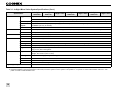
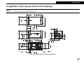
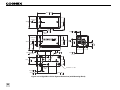
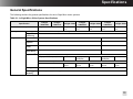
Specifications
General Specifications
The following sections list general specifications for the In-Sight Micro vision systems.
Table 3-1: In-Sight Micro Vision System Specifications
Specification
In-Sight
1020/1050
In-Sight
1100/1110
In-Sight 1100C
In-Sight version
4.3.0
In-Sight
1403/1413
In-Sight version
4.1.0
In-Sight 1403C
In-Sight version 4.1.0
Memory
Job/Program
64MB non-volatile flash memory; unlimited storage via remote network device.
Image
Processing
128MB
Sensor
1/3-inch CCD
1/1.8-inch CCD
Sensor
Properties
5.92mm diagonal, 7.4 x 7.4µm sq. pixels
8.8mm diagonal, 4.4 x 4.4µm sq. pixels
Resolution
(pixels)
640 x 480
1600 x 1200
Electronic
Shutter Speed
16µs to 1000ms
27µs to 1000ms
Acquisition1
Rapid reset, progressive scan, full-frame integration.
256 grey levels (8 bits/pixel)
In-Sight version
4.1.0
In-Sight 1400C
Minimum Firmware Requirement
Image
In-Sight version
4.3.0
In-Sight
1400/1410
In-Sight version
4.3.0
24 bit color
256 grey levels
(8 bits/pixel)
24 bit color
256 grey levels
(8 bits/pixel)
24 bit color
57 full frames per
second
60 full frames per
second
58 full frames per
second
14 full frames per
second
7 full frames per
second
Gain/Offset controlled by software.
60 full frames per second
Lens Type
CS-mount and C-mount (with 5mm extension, included).
CCD Alignment ±0.127mm (0.005in), (both x and y) from lens C-mount axis to center of imager.
Variability2
13
Table 3-1: In-Sight Micro Vision System Specifications (Cont.)
Specification
I/O
Trigger
In-Sight
1020/1050
In-Sight
1100/1110
In-Sight 1100C
In-Sight
1400/1410
In-Sight 1400C
In-Sight
1403/1413
In-Sight 1403C
1 opto-isolated, acquisition trigger input.
Remote software commands via Ethernet. (RS-232C available when using the optional CIO-MICRO or CIO-MICRO-CC I/O module.)
Discrete Inputs None. (Eight additional inputs available when using the optional CIO-MICRO, CIO-MICRO-CC or CIO-WENET (750-341) I/O module.)
Communications
Power
Mechanical
Environmental
Discrete
Outputs
2 opto-isolated, NPN/PNP high-speed outputs. (Eight additional outputs available when using the optional CIO-MICRO, CIO-MICRO-CC or
CIO-WENET (750-341) I/O module.)
Status LEDs
Network, 2 user-configurable.
Network
1 Ethernet port, 10/100 BaseT with auto MDI/MDIX. Supports DHCP (factory default), static and link-local IP address configuration.
Serial
None. (RS-232C: 1200 to 115,200 baud rates when connected to a CIO-MICRO or CIO-MICRO-CC I/O module).
Class
Class 2 Power over Ethernet (PoE) device.
Type
A and B.
Material
Die-cast zinc housing.
Finish
Painted.
Mounting
Four M3 threaded mounting holes (1/4 - 20 and M6 mounting holes also available on mounting block).
Dimensions
30mm (1.18in) x 30mm (1.18in) x 60mm (2.36in)
Weight
121g (4.27oz.) without mounting block.
146g (5.15oz.) with mounting block.
Temperature
Operating: 0°C to 45°C (32°F to 113°F)
Storage: -30°C to 80°C (-22°F to 176°F)
Humidity
90%, non-condensing (Operating and Storage)
Protection
IP51 with cables and lens attached.
Shock
80 G shock with 50 gram lens attached per IEC 68-2-27.
Vibration
10 G from 10-500 Hz with 50 gram lens attached per IEC 68-2-6.
Regulatory Compliance
CE, FCC, TUV SUD NRTL, RoHS
1. Maximum frames per second is job-dependent and based on the minimum exposure for a full image frame capture.
2. Expected variability in the physical position of the CCD, from vision system-to-vision system. This equates to ~ ±17 pixels on a 640 x 480 resolution CCD and ~ ±29
pixels on a 1600 x 1200 resolution CCD.
14
Specifications
In-Sight Micro Vision System Dimensional Drawings
Note:
• All dimensions are in millimeters [inches] and are for reference purposes only.
• All specifications may be changed without notice.
60.0 2.36
30.0 1.18
OPTICAL
AXIS
70.1 2.76
12.53 .493
OPTICAL
AXIS
30.0 1.18
9.0 .35
OPTICAL
AXIS
21.2 .83
15.0 .59
10.0 .39
11.0 .43
47.3 1.86
19.0 .75
1.5 .06
11.0 .43
22.0 .87
2X M3
19.0 .75
OPTICAL
AXIS
4.5[.18]
OPTICAL
AXIS
2.53 .100
2X M3
3.0[.12]
Figure 3-7: In-Sight Micro Vision System Dimensions
25
60.0 2.36
OPTICAL
AXIS
30.0 1.18
70.1 2.76
12.53 .493
OPTICAL
AXIS
9.0 .35
OPTICAL
AXIS
30.0 1.18
21.2 .83
38.2 1.50
11.0 .43
23.2 .91
19.7 .78
1/4-20 UNC -2B
12.7[.50]
13.2 .52
6.4 .25
19.0 .75
OPTICAL
AXIS
20.0 .79
2.53 .100
27.9 1.10
OPTICAL
AXIS
3X M6 X 1.0 -6H
22.0 .87
Figure 3-8: In-Sight Micro Vision System Dimensions (with Mounting Block)
26