1
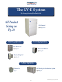
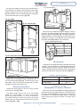
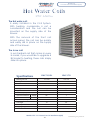
LV-E Series
Installation Manual
Includes:
LV-E Series Fan Coils
Product Specifications
From the Manufacturers of
Hi-Velocity SystemsTM
www.hi-velocity.com
Module LVE - LV-E Series Fan Coil Installation 011610
www.hi-velocity.com
www.hi-velocity.com
Table of Contents
Setting up your LV-E System
Filter Maintenance......................................................... 9
Unit Selection ................................................................ 5
Unit Configuration ....................................................... 5
Quality Assurance......................................................... 5
Fan Coil
Placement........................................................................ 5
Hanging Straps.............................................................. 5
Unit Configuration........................................................ 6
Clearances....................................................................... 6
Water Cooling Module (WCM/WM)
Piping the WCM/WM................................................... 7
System Efficiency/Performance................................... 9
Installation Check List.................................... 9
Wiring/Printed Circuit Board
EPC Printed Circuit Board........................................... 10
EPC Wiring Diagram.................................................... 11
Extended Wiring Diagram...................................... 12-13
EPC Circuit Board Pin Settings (Standard)............. 14
EPC Circuit Board Pin Settings (Metric).................. 15
Trouble Shooting
EPC Motor Not Running............................................ 16
Hot Water Coil Add-on
Piping the Hot Water Coil............................................ 7
Electrical Strip Heater (ESH) 24V................................................................................. 17
Low Air Flow............................................................... 18
Outdoor Unit - Electrical............................................ 19
Wiring the ESH.............................................................. 8
Return Air
Appendix Pages
LV-E Fan Coil Specs (Standard)
Pg. 20
LV-E Fan Coil Specs (Metric)
Pg. 21
Return Air Base..................................................... 8
WCM Coil Specs
Pg. 22
Filter Rack.................................................................. 8
Hot Water Coil Specs
Pg. 23
Filter................................................................................ 8
Electric Strip Coil Specs
Pg. 24
Hi-Velocity Air Purification System
Pg. 25
Quick Product Sizing Guide
Pg. 26
Warranty
Pg. 27
Return Cutout Dimensions.......................................... 8
Hi-Velocity Air Purification System... 9
User Guide
Indoor Air Quality......................................................... 9
Table of Contents
www.hi-velocity.com
The LV-E System
By Energy Saving Products Ltd.
All Product
Sizing on
Pg. 26
LV-E Fancoil
Specs Pgs. 20-21
Heating Options
Cooling Options
Hot Water Coil
Water Coil Module
Specs Pg. 23
Specs Pg. 22
Electric Strip Coil
Specs Pg. 24
Other Options
Hi-Velocity Air Purification System
Return Air
Specs Pg. 25
Pg. 8
-4-
© 1995-2009 Energy Saving Products Ltd.
Module LVE
LV-E Series Fan Coil Installation (5/27)
www.hi-velocity.com
When sizing an LV-E fan coil for a residential system,
it is necessary to have an accurate heat loss/gain done
for the structure. This will ensure the proper equipment is
used for cooling and heating. A heat loss/gain is done for
each room, with all rooms added together to find the total
BTUH load for the building. With the total load known, the
appropriate fan coil can be chosen from Pgs. 20 and 21.
The LV-E
temporary
fan coil is not to be used as
heating/cooling
during
Fan coils are to be located indoors, however, attic,
crawl space and garage conditions are fully acceptable.
The fancoil unit can be positioned in a Horizontal, Hi-Boy,
or Counterflow position and can be suspended from the
ceiling or placed directly on the floor.
When potential for gravity flow of the hot water exists,
spring check valves may be needed on both the supply
and return lines.
the
construction of the structure. If used in this
Please
capacity all warranties will be null and void.
read the
ENTIRE
manual before
beginning installation as this will help avoid
mistakes that may cost time and money.
Fan coil units specified in this section shall be designed
as a closed loop hydronic fan coil system, with published
BTUH ratings and entering water temperatures between
110°F and 190°F. The system shall allow for heating, TX
or chilled water cooling, and heat pump applications with
electric coil back-ups. Entering water temperature and
BTUH outputs shall match performances listed on Pgs. 20
and 21.
Quality Assurance
Fan coil units shall be a total indoor air quality system
complete with heating, cooling and air filtration, with the
possibility of humidity control and fresh air make up. The
fan coil must be factory manufactured, assembled and
tested.
All equipment furnished under this specification
shall comply with the standards set out by the following
standards organizations:
CSA Canadian Standards Association
CE
European Conformity
UL Underwriters Laboratories
The fan coil units shall be designed, rated, and approved
by CSA/UL.
The fan coil units shall have pre-wired controls consisting
of a 24V transformer and printed circuit board. The circuit
board shall be capable of providing both heating and
cooling. Motors shall be 115/220/50/60/1 with published
amp draws.
Sweat water connections are 3/4” for the LV-E 1050
and 1” for the LV-E 1750. All lines should be piped so as
not to restrict use of the access panels, filter section, or
electrical enclosure.
Refer to the appendix pages at the back of this manual
for all specifications, measurements, etc.
Disclaimer
Energy Saving Products Ltd. reserves the right to
discontinue, make changes to, and add improvements
upon its products at any time without public notice or
obligatiion. The descriptions and specifications contained
in this manual were in effect at printing. Some illustrations
may not be applicable to your unit.
Fan Coils
The LV-E fan coil is manufactured with a direct drive,
permanently lubricated motor that is mounted within the
blower. All LV-E fan coils are single side access. The
blower assembly can be easily slid out by removing the
electrical box and then removing the three mounting
bolts that attach the blower to the center plate.
Placement
When installing the fan coil, keep these points in mind:
-
-
-
Serviceability and access to the unit.
Maximizing usable floor space.
Location of heating/cooling source to the
fan coil.
Hanging Strap Kit
The Hanging Strap Kits are designed to suspend a
horizontal or vertical fan coil. The nylon straps will absorb
most of the vibration generated by the fan coil system,
eliminating any sound transfer. The hanging strap kit is
not recommended for the LV-E-1750.
Module LVE - LV-E Series Fan Coil Installation (5/27)
-5-
© 1995-2009 Energy Saving Products Ltd.
Module LVE
LV-E Series Fan Coil Installation (6/27)
www.hi-velocity.com
As previously stated, the fancoil can be positioned in
many different orientations. When placed in the Hi-Boy
position, supply air is fed from the top of the unit. (Fig.
01) When placed in the Counterflow position, supply air
is fed downwards from the unit. (Fig. 02)
Fig. 04 - Nylon Straps
04b
04a
Fig. 01 - Hi-Boy
Fig. 02 - Counter flow
04c
Secure the nylon straps to the joist or support, it may be
necessary to install a support across the joists to properly
fasten the Nylon Straps (Fig. 05). The Nylon Straps are
always installed in a vertical position; they should never be
installed at an angle. It is acceptable to put a 90º twist in
the Nylon Straps (Fig. 05a), do not exceed 90º.
Fig. 05 - Support might be needed
Fig. 03 - Horizontal installation
Fig. 05a - 90° twist
Clearances
Clearance is only needed on the access side of the units.
However, ensure that there is a small space between the
unit and any other surface to prevent vibration transfer. In
order to maintain and service the fan coil unit, the minimum
clearances required on the access side are (Table 01).
Table 01 – Fan coil clearances
Quite often, the best location for the fan coil unit is
suspended from the ceiling of the mechanical room, in
the horizontal position (Fig. 03). This will allow for more
floor space in the room, and will minimize the duct work
needed to connect to the fan coil unit.
Fancoil Unit Only
Attach the metal flanges to the four facing corners
of the fancoil unit (Fig. 04a).
Unit
LV-E 1050
LV-E 1750
Inches
22”*
32”
*Add an additional 4” for Electric Strip Coils
(not available for the LV-E 1750)
Refrigerant Cooling Module
Due to the size of the RCM/RPM-E Cooling Modules and
the high volume of air produced by the LV-E Fancoil Unit,
the use of the RCM/RPM-E coils with the LV-E Fancoil is
not advised. For refrigerant cooling needs, a third party
blow through coil such as an A-Frame or N-Frame coil is
suitable.
The Nylon Straps need to be cut to the desired
length (4” or more). Make a 1⁄4” hole 1” from the end
of the nylon strap. Slide the 1 1⁄4” bolt into the hole of
the metal flange then into the nylon strap, secure with
washer and nut. Repeat this at each end of the nylon
straps (Fig. 04b – 04c).
Module LVE - LV-E Series Fan Coil Installation (6/27)
-6-
© 1995-2009 Energy Saving Products Ltd.
Module LVE
LV-E Series Fan Coil Installation (7/27)
www.hi-velocity.com
Water Coil Module (WCM/WM)
Fig. 07 - Hot Water Coil easily slides into the fan coil
The water coil comes as a module and must be
installed in the vertical position on the return air side of
the fan coil. The WCM/WM come supplied with two L
mounting brackets for connection to the fan coil (Fig. 06).
For WCM/WM dimensional information and sweat water
connection sizes refer to Pg. 22.
Piping the WCM/WM
When the potential for gravity flow of the hot
water exists, check valves may be needed on both
the supply and return lines. Fig. 08 and 09 give an
example of this. All lines should be piped so as not
to restrict access to the front panels, filter section, or
electrical enclosure. Size your supply and return lines
according to Table 02.
Table 02 – WCM/WM pipe sizing
Zone BTUH
Heat loss
Pipe Size
up to 40 feet
Pipe Size
40 – 100 feet
⁄8”
3
⁄4”
1”
1”
1 1⁄4”
0 - 35,000
5
35,001 - 70,000
3
70,001 - 140,000
⁄4”
Fig. 08 - Hot water tank: Side take-offs
SUPPLY
H
Fig. 06 - Mounting Brackets
Domestic
hot water
mixing valve
(optional)
C
RETURN
Fan Coil
Domestic
cold water
C
H
Dual
Purpose
hot water
tank
Hot Water Coil Add-on
The Hot Water Coil Add-on is easily installed in the LV-E
fan coil. With heating, condensate is not a consideration
and the coil can be mounted on the supply side of the
blower (Fig. 07).
With the removal of the front panels, the coil can be slid
in place on the supply side of the blower. For Hot Water
Coil dimensional information and sweat water connection
sizes refer to Pg. 23.
Piping the Hot Water Coil
SUPPLY
RETURN
Fig. 09 - Hot water tank: Without side take-offs
SUPPLY
H
Domestic
hot water
mixing valve
(optional)
RETURN
C
Fan Coil
Domestic
cold water
C
H
Dual
Purpose
hot water
tank
Fig. 08 and 09 illustrate typical pipe runs from a dual
purpose hot water tank to a fan coil. These drawings are
only for reference as all piping has to be run according
to local code.
Module LVE - LV-E Series Fan Coil Installation (7/27)
-7-
© 1995-2009 Energy Saving Products Ltd.
Module LVE
LV-E Series Fan Coil Installation (8/27)
www.hi-velocity.com
Electrical Strip Heater (ESH)
The Electrical Strip Heater slides into the fan coil, on
the supply side of the blower (Fig. 07). Once the front
access doors have been removed, the ESH can be slid
into place.
The ESH is labeled with a directional airflow sticker;
when placing the ESH the sticker shall be in the direction
of the air flow. Currently, the ESH is only available for use
with the LV-E 1050
Wiring the Electrical Strip Heater
Before wiring in the ESH, make sure all power sources
are disconnected. The wiring diagram is on the inside of
the ESH front panel, or refer to Pg. 11. Use only wires
suitable for 167ºF (75ºC); wires shall be sized according
to local electrical code.
Use only class 2 wiring for the Control Circuit
connections between the heater terminal 1, terminal 2
and the zone valve terminals. Please note, the ESH must
be wired to a dedicated breaker, separate from the fan
coil.
Once the placement of the return has been decided,
the return air knockout(s) can be marked and cut (Fig.
10). The pre-measured guide cuts supplied with the fan
coil should always be used; this will guarantee maximum
airflow across the coil.
Return Air Base (Optional)
Energy Saving Products manufactures a return air
base with a built in filter rack that matches up to the
fan coil units.
The return air base comes complete with a 1”
filter and 1” filter rack. The filter is a 3 medium filter
approximately 14% efficient, and can be replaced
with any aftermarket filter. All Return Air bases come
acoustically lined with half-inch sound absorbing
insulation.
Table 04 – Return Air Base dimensions
A
B
C
D
24”
181⁄2”
191⁄2”
11⁄8”
213⁄4”
LV-E 1750
24”
241⁄4”
261⁄2”
11⁄8”
213⁄4”
Fig. 11 – Return Air Design
Please see Pg. 24 for Electrical Strip Heater
Specifications.
Two 11⁄8” Rails (D) for fan coil
Placement and Filter Holder
Return Air
The return air duct is not supplied with the LV-E Fancoil
System. It is to be supplied and installed by the contractor.
The return air and fresh air make-up ducts are to be
installed according to local building code.
Return Air Cutout
11⁄8” Opening
EA
D
All LV-E fan coils are shipped with the return air
knockouts pre-measured for multiple configurations.
Table 03 contains the pre-measured dimensions for the
return air knockouts.
C
Table 03 – Return Air Cutout Dimensions
Model
Dimensions
LV-E 1050
141/2” X 131/2”
LV-E 1750
21” X 177/8”
Fig. 10 - Return air cutout
E
LV-E 1050
B
Filter Rack (Optional)
Also available from Energy Saving Products is a 3” Filter
Rack. Filters are 1 inch thick, 3 medium filters approximately
14% efficient. Any after market filter may be used with both
the Hi-Velocity Return Air Base and Filter Rack.
Table 05– Filter Rack dimensions
A
B
C
D
LV-E 1050
3”
18 ”
19 ”
1 ”
LV-E 1750
3”
24 ”
26 ”
11/8”
Module LVE - LV-E Series Fan Coil Installation (8/27)
-8-
1/2
1/4
1/2
1/2
1/8
© 1995-2009 Energy Saving Products Ltd.
Module LVE
LV-E Series Fan Coil Installation (9/27)
www.hi-velocity.com
Hi-Velocity Air Purification System
System Efficiency/Performance
B
A
C
Designed for the Hi-Velocity System, the HE PS
gives consumers unsurpassed indoor air quality. The
HE PS will work at the airflow rates of the LV-E 1050
only. For 3 stage filtration on the LV-E 1750, we
recommend using the HE PS 1750. See Pg. 25 for
specifications.
Table 06 –HE PS dimensions
HE PS w/ Flange
A
B
C
25 ’
17 ”
10”
3/4
3/4
A big misconception that people have is that by
turning off the air conditioning when they leave home,
they save on cooling costs. This is not necessarily
true as the system will need to run longer and harder
when pulling the house down to temperature after
being shut off for a large amount of time. Keeping the
temperature within a small range when there are no
loads from human use will result in less overall energy
consumption.
Installation Checklist
Ensure that all electrical connections are tight, and
that any packing or shipping restraints are removed
from both the fan coil, and the outdoor unit. With the
power to the condensing unit off, check the thermostat
for normal operation and proper airflow from all vents.
Do not run the fan coil without a filter in place.
LV-E User Guide
Indoor Air Quality (IAQ)
Ensure that there is always a filter in place and check
every month to ensure that the filter is clean. The amount
of time between filter changes and cleaning will be
dependant upon the living habits of the homeowner. With
a clean air filter, you not only have cleaner air to breathe,
but you will also help maintain unit efficiency, as well as
increase the operating life of the unit.
Filter Maintenance
The 1” 3 medium filters supplied by Energy Saving
Products Ltd. can be cleaned and re-used. If the filter
needs cleaning, the system should first be shut down
and the filter removed. Once out of the unit, the filter
can be vacuumed on the pink side and washed on the
white side. Once the filter has been vacuumed, cleaned,
and completely dried, it can be replaced in the unit. Note
that the pink side of the filter faces the blower and the
white side towards the return air. A filter can generally
be cleaned a few times, if re-used too often it will restrict
airfow.
Observe the system pressures during the initial startup and charging of the system. Refer to the outdoor or
indoor coil manufacturer’s charging guidelines. Check
the voltage and amp draw of both the fan coil, and the
outdoor unit. The voltages must be within 10% of the
rating plate data. If more than 10% is noted, contact
your local electrical company. Check that the amp
draws of both units are within the information printed
on the unit rating plates.
In the event of difficulty during
the start-up procedure, please
refer to the trouble shooting
flow charts (Pgs. 16-19) to assist
you in determining the problem.
Module LVE - LV-E Series Fan Coil Installation (9/27)
-9-
© 1995-2009 Energy Saving Products Ltd.
Module LVE
LV-E Series Fan Coil Installation (10/27)
www.hi-velocity.com
EPC Circuit Board/Control Board
Line Voltage
Control Interface
Auxiliary Relay
Connections
Low Voltage
Control Interface
Anti-Ice
Control
EPC Circuit
Condensing
Board
Unit
Thermostat
Connections
Hot Water
Zone Valve
Timer Chip
Timer On/Off Switch
20 VA Transformer
Energy Saving Products Ltd. now utilizes automatic voltage and frequency recognition
circuitry designed for the
Connections
national and international market. This unique feature will automatically recognize and adjust to the voltage and
frequency input. It doesn’t matter if it is 115 or 230 volt, 50 or 60 cycle, our electronics will adjust to the input
automatically.
The Circulator Timer Chip on our circuit board will energize the pump for 5 minutes every 24 hours. This timing
cycle starts when power is turned on to the fan coil unit, and will be engaged at the same time every day. If you
wish to have the timer cycle operate at a specific time of day, simply turn off power to the fan coil unit for three
seconds at that time, and then turn the power back on. If you do not need to use the timer circuit, move the
jumper header from the ON pins to the OFF pins and it will be disabled.
Low Voltage
Interface
EPC Control
Board
Dip Switch
Programmable
Settings
Line Voltage
Interface
Motor
Interface
Unit Configuration
The LV-E unit utilizes mass flow technology and will attempt to provide constant air delivery throughout the
programming range. Whereas a conventional motor would slowly lose airflow due to a condition such as a dirty filter,
the EPC Motor and mass flow program will attempt to maintain proper airflow rates through such a condition. This
is achieved through control of the voltage and frequency of power provided to the motor. The LV-E System is field
programmable from 1.5 to 5 tons of cooling with the use of an adjustable control board, with the tonnage being set by
the 8 pins on board. See the Dip Switch Control graphic for reference. Detailed information on pin settings is supplied
on Page 14.
Dip Switch Control:
(Factory Setting, set for 1.5 tons)
Each programmed tonnage will have up to 5 adjustments for on-site fine tuning which is changed using pins 6,7 and
8.
Module LVE - LV-E Series Fan Coil Installation (10/27)
-10-
© 1995-2009 Energy Saving Products Ltd.
Module LVE
LV-E Series Fan Coil Installation (11/27)
www.hi-velocity.com
LV-E Fan Coil - EPC Wiring Diagram
This wiring diagram is included on all of the LV-E models. The power inputs as well as the various connection terminals
are identified, helping you to quickly wire in the required devices.
FOR SINGLE STAGE OPERATION USE W2 & Y2 TERMINALS
CAUTION
N - neutral
L - line voltage
A1 - auxiliary normally open
A2 - auxiliary normally closed
A3 - auxiliary common
DISCONNECT THE ELECTRIC
POWER BEFORE SERVICING
ATTENTION
DECCONNECTER DU CIRCUIT
D’ALIMENTATION ELECTRIQUE
AVANT L’ENTRE-TIEN
X1 - freeze stat terminal
X2 - freeze stat terminal
H1 - condensing unit 24v output
C - condensing unit 24 vac common
Z1 - heating mode 24v output
Z1 - heating mode 24v output
WARNING: HIGH VOLTAGE
tHIS
DEVICE
CONTAINS
CAPACITORS
WHICH STORE POTENTIALLY DANGEROUS
AMOUNTS OF ENERGY. ALLOW 5 MINUTES
AFTER DISCONNECTING POWER FROM THE
DRIVE BEFORE DISCONNECTING THE MOTOR.
AVERTISSEMENT: HAUT VOLTAGE
CET APPAREIL EST MUNI DE CONDENSATEURS
QUI EMMAGASINENT UN MONTANT D’ÉNERGIE
POTENTIELLEMENT
DANGEREUX.
AVANT
DE DÉCONNECTER LE MOTEUR, ATTENDRE
5 MINUTES APRÈS AVOIR DÉBRANCHÉ
L’ALIMENTATION ÉLECTRIQUE DE LA DRIVE.
minimum factory dip settings
black is dip switch setting
ON
1
2
3
4
5
6
7
LV-E 1750 400 CFM/TON
4 TONS/94.3 MBH @ 10 GPM
LV-E 1050 400 CFM/TON
3 TONS/64.6 MBH @ 5 GPM
LV-E 1050 400 CFM/TON
2 TONS/47.5 MBH @ 5 GPM
ON
8
1
2
3
4
5
6
7
LV-E 1750 350 CFM/TON
5 TONS/112.1 MBH @ 10 GPM
ON
1
8
2
3
4
5
6
7
ON
8
1
2
3
4
5
6
7
8
Heating Ratings Based Upon 160oF EWT
NOTES:
1) USE THERMOSTAT FAN SWITCH TO DISABLE/ENABLE
CONTINUOUS FAN.
2) ‘C’ TERMINAL ON THERMOSTAT (COMMON) IS NOT
NEEDED FOR SOME THERMOSTATS. CONSULT THERMOSTAT
INSTRUCTIONS FOR DETAILS.
3) A3 (AUXILIARY RELAY COMMON) CAN BE USED WITH A1 AND/
OR A2 AS DRY CONTACTS, ARMED 24v FROM THE ‘R’ TERMINAL,
OR ARMED FROM THE ‘L’ TERMINAL.
4) AUXILIARY RELAY TIMER ACTIVATES CIRCUIT FOR 5 MINUTES
EVERY 24 HOURS STARTING WHEN POWER IS APPLIED TO THE
UNIT. RED LIGHT IS ON WHEN AUXILIARY RELAY IS ACTIVATED.
5) SEE INSTALLATION MANUAL FOR MORE DETAILED WIRING
DIAGRAMS AND DIP SWITCH SETTINGS.
6) FAILURE TO READ AND FOLLOW ALL INSTRUCTIONS
CAREFULLY BEFORE INSTALLATION COULD CAUSE PERSONAL
INJURY AND/OR PROPERTY DAMAGE.
Module LVE - LV-E Series Fan Coil Installation (11/27)
-11-
© 1995-2009 Energy Saving Products Ltd.
Module LVE - LV-E Series Fan Coil Installation (12/27)
-12-
AUXILIARY RELAY
(HEATING)
C Z1 C H1 X2 X1
C
G
R
Y
THERMOSTAT
N
A1
A2
E
AUXILIARY RELAY
(HEATING)
C Z1 C H1 X2 X1
W1 W2
G
R
Y
THERMOSTAT
C
N
A1
A2
A3
L
ANTI-ICE
CONTROL
W1 W2 C G R Y2 Y1 D O/B
Z1 - HEATING MODE
24V OUTPUT
(W2 Only)
C 24v
E
C
A1 AND A3 HEATING MODE
AUXILIARY CONTACT
W1 And W2 Only
X1 AND X2 WIRES TO ANTI-ICE CONTROL,
CONDENSING UNIT “Y” AND “C”
SIGNAL FROM H1 AND C TO
COMPLETE SIGNAL
Y
CONDENSER
C
G
R
Y
THERMOSTAT
O/B
C
Y1 O/B
R
A1 AND A3 HEATING MODE
AUXILIARY CONTACT
W1 And W2 Only
X1 AND X2 WIRES TO ANTI-ICE CONTROL,
CONDENSING UNIT “Y” AND “C”
SIGNAL FROM H1 AND C TO
COMPLETE SIGNAL
Y2
E
AUXILIARY RELAY
(HEATING)
C Z1 C H1 X2 X1
W3
G
R
Y2
THERMOSTAT
C
Y1
O/B
N
A1
A2
A3
L
ANTI-ICE
CONTROL
W1 W2 C G R Y2 Y1 D O/B
Z1 - HEATING MODE
24V OUTPUT
(W2 Only)
C 24v
Y2
Y1 O/B
R
C
24 VAC
RELAY WIRING
115 VAC
RELAY WIRING
N
X1
C
C
Z1
H1
X2
Z1
G
C
R Y2 Y1
H1 X2 X1
D
L
O/B
N
A1
A2
A3
N
A1
A2
115 V TO
CIRCULATOR
115v
CIRCULATOR
X1 - FREEZE STAT
X2 - FREEZE STAT
H1 - CONDENSING UNIT 24V OUTPUT (Y)
C - 24 VAC COMMON
Z1 - HEATING MODE 24V OUTPUT
C - 24 VAC COMMON
N - NEUTRAL
L - LINE VOLTAGE
A1 - AUXILIARY NORMALLY OPEN
A2 - AUXILIARY NORMALLY CLOSED
A3 - AUXILIARY COMMON
12615-124 Street, Edmonton, AB T5L-0N8
ESP315.06
R - 24VAC OUTPUT
W1 - FIRST STAGE HEAT
W2 - SECOND STAGE HEAT
(OR SINGLE STAGE)
Y1 - FIRST STAGE COOLING
Y2 - SECOND STAGE COOLING
(OR SINGLE STAGE)
C - 24 VAC COMMON
G - THERMOSTAT FAN SWITCH
D - DEHUMIDIFICATION
O/B - HEATPUMP REVERSING VALVE
L
A3
DRY CONTACTS AND 115 VAC
RELAY WIRING
EXTERNAL
SPDT RELAY
24 VAC COIL
FOR SINGLE STAGE OPERATION
USE W2 & Y2 TERMINALS
W1 W2 C
C
DRY CONTACT
TO BOILER T T
SAMPLE AUXILIARY RELAY WIRING OPTIONS FOR HEATING
(W1 OR W2)
DRY CONTACTS AND 115 VAC
RELAY WIRING
EXTERNAL
SPDT RELAY
24 VAC COIL
DRY CONTACT T
TO BOILER T
SAMPLE AUXILIARY RELAY WIRING OPTIONS FOR HEATING (1 STAGE - W2 ONLY)
DRY CONTACTS
RELAY WIRING
N
A1
A1
N
A2
A2
A1
L
A2
L
A3
R
A3
L
A3
Energy Saving Products
A1 AND A3 HEATING MODE
AUXILIARY CONTACT
W1 And W2 Only
Y2 WIRE TO ANTI-ICE CONTROL
TO INTERRUPT THE
CONDENSERS “Y2” SIGNAL
C
2 Stage Cooling 3 Stage Heating
CONDENSER
Heatpump
W1 W2
N
A1
A2
W1 W2 C G R Y2 Y1 D O/B
AUXILIARY RELAY
(HEATING)
A3
C Z1 C H1 X2 X1
ANTI-ICE
CONTROL
A3
1 Stage Cooling 2 Stage Heating
W
Z1 - HEATING MODE
24V OUTPUT
(W2 Only)
C 24v
L
A1 AND A3 HEATING MODE
AUXILIARY CONTACT
W1 And W2 Only
X1 AND X2 WIRES TO ANTI-ICE CONTROL,
CONDENSING UNIT “Y” AND “C”
SIGNAL FROM H1 AND C TO
COMPLETE SIGNAL
Y
CONDENSER
L
ANTI-ICE
CONTROL
W1 W2 C G R Y2 Y1 D O/B
Z1 - HEATING MODE
24V OUTPUT
(W2 Only)
C 24v
C
1 Stage Cooling 2 Stage Heating
CONDENSER
Heatpump
TM
1 Stage Cooling 1 Stage Heating
SAMPLE AUXILIARY RELAY WIRING OPTIONS FOR HEATING (W1 OR W2)
Module LVE
LV-E Series Fan Coil Installation (12/27)
www.hi-velocity.com
Extended Wiring Diagrams
Extended wiring diagrams for the various applications the LV-E model can be used for. If you don’t find the wiring
configuration you require, please call the technical department at Energy Saving Products Ltd. for further assistance.
© 1995-2009 Energy Saving Products Ltd.
Module LVE
LV-E Series Fan Coil Installation (13/27)
www.hi-velocity.com
LV-E Fan Coil - 24V Wiring Controls
W1
W1 input to 1st (low stage) heat calls. Active when R is applied. Activates 1st
stage heat fan and Auxiliary Relay.
(W1 operates at 60% of W2 Fan Speed)
W2
W2 input to 2nd (high/primary stage) heat calls. Active when R is applied.
Activates 2nd stage heat fan, Auxiliary Relay and 24V to Z1
(W2 operates at 320/280 CFM per ton, refer to dip setting)
C
24V supply common
G
G input for thermostat fan switch. Active when R is applied
(G operates at 50% of Y2 Fan Speed)
R
24V supply
Y2
Y2 input to 2nd (high/primary stage) cooling or heat pump call. Active when R is
applied. Activates 2 stage cooling fan speed, activates X1 with 24V for freeze stat
and condenser connections
(Y2 operates at 400/350 CFM per ton, refer to dip setting)
Y1
Y1 input to 1st (low stage) cooling or heat pump calls. Active when R is applied.
Activates 1 stage cooling fan speed.
(Y1 operates at 60% of Y2 Fan Speed)
D
O/B
24V input required from dehumidistat switch activates blower system to
320/280 CFM per ton from dip setting. Y2 must be activated rom thermostat.
(D operates at 320/280 CFM per ton, refer to dip setting)
Blind contact for condenser heat pump from thermostat
X1
24V Signal with calls from Y2, powers Freeze Stat
X2
Freeze Stat connection return signal
H1
24V Signal to Y on Condenser
C
Common for Condensing Unit
Z1
C
24V supply on W2 call
Common
*Note: X1 to X2 recommended to be wired to Freeze Stat (Anti-Ice Control)
If Freeze Stat is not used, a jumper between X1 to X2 must be installed
to complete the H1 - 24V Signal to Y on Condenser (i.e. Chilled Water Systems)
Module LVE - LV-E Series Fan Coil Installation (13/27)
-13-
v.03
© 1995-2009 Energy Saving Products Ltd.
Module LVE
LV-E Series Fan Coil Installation (14/27)
www.hi-velocity.com
EPC Circuit Board Pin Settings and Air Flow Data (Standard)
BLACK INDICATES DIP SWITCH POSITION. A heat loss/gain must be done prior to selecting an LV-E unit.
Once an accurate heat loss/gain is completed, select the appropriate LV-E unit and the correct pin settings.
Model: LV-E 1050
Model: LV-E 1050
350 CFM/Ton
Cooling: 1.5 Ton
ON
1
2
3
4
5
6
7
8
Pin Setting 0010-0001
Model: LV-E 1050
ON
2
3
4
5
6
7
8
Pin Setting 0010-0010
Model: LV-E 1050
ON
2
3
4
5
6
7
8
Pin Setting 0010-0011
Model: LV-E 1050
ON
2
3
4
5
6
7
110
CFM
700
Watts
185
CFM
875
Watts
245
350 CFM/Ton
Cooling: 3.0 Ton
1
Watts
350 CFM/Ton
Cooling: 2.5 Ton
1
525
350 CFM/Ton
Cooling: 2.0 Ton
1
CFM
8
Pin Setting 0110-0001
CFM
1050
Watts
440
Model: LV-E 1050
Cooling: 1.5 Ton
ON
1
2
3
4
5
6
7
8
Pin Setting 0000-0011
Model: LV-E 1050
Cooling: 2.0 Ton
ON
1
2
3
4
5
6
7
8
Pin Setting 0010-0101
Model: LV-E 1050
Cooling: 2.5 Ton
ON
1
2
3
4
5
6
7
8
Pin Setting 0011-0100
Model: LV-E 1050
Cooling: 3.0 Ton
ON
1
2
3
4
5
6
7
8
Pin Setting 0111-0100
400 CFM/Ton
CFM
600
Watts
140
400 CFM/Ton
CFM
800
Watts
205
400 CFM/Ton
CFM
1000
Watts
290
400 CFM/Ton
CFM
1200
Watts
515
Model: LV-E 1750
Model: LV-E 1750
350 CFM/Ton
Cooling: 3.0 Ton
ON
1
2
3
4
5
6
7
8
Pin Setting 0101-0110
Model: LV-E 1750
ON
2
3
4
5
6
7
8
Pin Setting 1000-0100
Model: LV-E 1750
ON
2
3
4
5
6
7
8
Pin Setting 1100-0011
Model: LV-E 1750
ON
2
3
4
5
6
7
230
CFM
1225
Watts
310
CFM
1400
Watts
440
350 CFM/Ton
Cooling: 5.0 Ton
1
Watts
350 CFM/Ton
Cooling: 4.0 Ton
1
1050
350 CFM/Ton
Cooling: 3.5 Ton
1
CFM
8
Pin Setting 1101-0110
CFM
1750
Watts
695
Model: LV-E 1750
Cooling: 3.0 Ton
ON
1
2
3
4
5
6
7
8
Pin Setting 1000-0101
Model: LV-E 1750
Cooling: 3.5 Ton
ON
1
2
3
4
5
6
7
8
Pin Setting 1100-0011
Model: LV-E 1750
Cooling: 4.0 Ton
ON
1
2
3
4
5
6
7
8
Pin Setting 1011-0110
Model: LV-E 1750
Cooling: 5.0 Ton
ON
1
2
3
4
5
6
7
8
Pin Setting N/A
400 CFM/Ton
CFM
1200
Watts
270
400 CFM/Ton
CFM
1400
Watts
440
400 CFM/Ton
CFM
1600
Watts
500
400 CFM/Ton
CFM
N/A
Watts
N/A
Black indicates dip switch position:
ON
OFF
Module LVE - LV-E Series Fan Coil Installation (14/27)
-14-
© 1995-2009 Energy Saving Products Ltd.
Module LVE
LV-E Series Fan Coil Installation (15/27)
www.hi-velocity.com
EPC Circuit Board Pin Settings and Air Flow Data (Metric)
BLACK INDICATES DIP SWITCH POSITION. A heat loss/gain must be done prior to selecting an LV-E unit.
Once an accurate heat loss/gain is completed, select the appropriate LV-E unit and the correct pin settings.
Model: LV-E 1050
Model: LV-E 1050
47 L/s per kW
Cooling: 1.5 Ton
ON
1
2
3
4
5
6
7
8
Pin Setting 0010-0001
Model: LV-E 1050
ON
2
3
4
5
6
7
8
Pin Setting 0010-0010
Model: LV-E 1050
ON
2
3
4
5
6
7
8
Pin Setting 0010-0011
Model: LV-E 1050
ON
2
3
4
5
6
7
110
L/s
330
Watts
185
L/s
413
Watts
245
47 L/s per kW
Cooling: 3.0 Ton
1
Watts
47 L/s per kW
Cooling: 2.5 Ton
1
248
47 L/s per kW
Cooling: 2.0 Ton
1
L/s
8
Pin Setting 0110-0001
L/s
496
Watts
440
Model: LV-E 1050
Cooling: 1.5 Ton
ON
1
2
3
4
5
6
7
8
Pin Setting 0000-0011
Model: LV-E 1050
Cooling: 2.0 Ton
ON
1
2
3
4
5
6
7
8
Pin Setting 0010-0101
Model: LV-E 1050
Cooling: 2.5 Ton
ON
1
2
3
4
5
6
7
8
Pin Setting 0011-0100
Model: LV-E 1050
Cooling: 3.0 Ton
ON
1
2
3
4
5
6
7
8
Pin Setting 0111-0100
54 L/s per kW
L/s
283
Watts
140
54 L/s per kW
L/s
378
Watts
205
54 L/s per kW
L/s
472
Watts
290
54 L/s per kW
L/s
566
Watts
515
Model: LV-E 1750
Model: LV-E 1750
47 L/s per kW
Cooling: 3.0 Ton
ON
1
2
3
4
5
6
7
8
Pin Setting 0101-0110
Model: LV-E 1750
ON
2
3
4
5
6
7
8
Pin Setting 1000-0100
Model: LV-E 1750
ON
2
3
4
5
6
7
8
Pin Setting 1100-0011
Model: LV-E 1750
ON
2
3
4
5
6
7
230
L/s
578
Watts
310
L/s
661
Watts
440
47 L/s per kW
Cooling: 5.0 Ton
1
Watts
47 L/s per kW
Cooling: 4.0 Ton
1
496
47 L/s per kW
Cooling: 3.5 Ton
1
L/s
8
Pin Setting 1101-0110
L/s
826
Watts
695
Model: LV-E 1750
Cooling: 3.0 Ton
ON
1
2
3
4
5
6
7
8
Pin Setting 1000-0101
Model: LV-E 1750
Cooling: 3.5 Ton
ON
1
2
3
4
5
6
7
8
Pin Setting 1100-0011
Model: LV-E 1750
Cooling: 4.0 Ton
ON
1
2
3
4
5
6
7
8
Pin Setting 1011-0110
Model: LV-E 1750
Cooling: 5.0 Ton
ON
1
2
3
4
5
6
7
8
Pin Setting N/A
54 L/s per kW
L/s
566
Watts
270
54 L/s per kW
L/s
660
Watts
440
54 L/s per kW
L/s
755
Watts
500
54 L/s per kW
L/s
N/A
Watts
N/A
Black indicates dip switch position:
ON
OFF
Module LVE - LV-E Series Fan Coil Installation (15/27)
-15-
© 1995-2009 Energy Saving Products Ltd.
Module LVE
LV-E Series Fan Coil Installation (16/27)
www.hi-velocity.com
Start
Trouble Shooting: EPC Motor not Running
Ensure 4 Pin Input
Voltage Plug is
properly connected to
Printed Circuit Board
(PCB)
Ensure breaker is
turned on
Open doors to
inspect Controller
N
Green light
present on Motor
Control Board
(MCB)
Verify that the
input line voltage is
present on the PCB via
the “L” and “N” screw
terminals on the
auxiliary power block.
N
Check for broken or
loose wires from
breaker to Unit
N
Y
Verify that
input voltage is
present on PCB via
“L” and “N” screw
terminals.
Y
Orange
flashing light
present
on MCB?
Y
Indicates Controller
has entered an
unnatural state and
gone into safe mode
to prevent damage
to the Motor
Control Board
Y
Once voltage
presence is verified on
PCB, shut power off
to the unit
N
Ensure the 4 Pin Plug
from Motor is properly
connected to MCB
Ensure that 9 wire
plug is connected to MCB
and PCB (Red Wire on
PCB side lines up with
W1 terminal on PCB)
Contact
Energy Saving
Products Ltd. to
return board for
no-charge
change out upon
completion of
RMA form
To eliminate outside
variables, remove all
thermostat wires
from the PCB
Ensure that you have
24v being supplied by
the Transformer. This
can be done via the
“R” and “C”
thermostat terminals
on the PCB
Ensure that 4 Pin
Input Voltage Plug is
properly connected
to MCB.
Call Tech Support
1-888-652-2219
Y
N
Allow 1-2 minutes
for the capacitors
to charge.
Green light on?
Y
N
24v present on
Circuit Board?
Allow 5 minutes for
capacitors to dissipate,
then reconnect power
Fan Running?
Y
Return to start to
ensure motor is
running properly
N
Refer to 24V Trouble
Shooting
Set system for
operation by placing a
jumper between the
R and Y2 terminals on
the PCB. Wait a few
seconds as the EPC
motor ramps up slowly.
Module LVE - LV-E Series Fan Coil Installation (16/27)
-16-
Finished
PCB = Printed Circuit Board
MCB = Motor Control Board
© 1995-2009 Energy Saving Products Ltd.
Module LVE
LV-E Series Fan Coil Installation (17/27)
www.hi-velocity.com
Trouble Shooting: 24 Volt
24v THERMOSTAT TO PCB
Start
Verify Line Voltage
power between
L and N
Line Voltage plug
connected?
N
Connect Line
Voltage plug and
return to start
N
Y
Y
Check that Line
Voltage wiring from
breaker is proper
Verify 24v power
between R & C
N
Check
Transformer Plugs
Connected?
N
Return to
Start
Connect
Transformer Plugs
and return to start
Y
Y
Replace
Transformer
Signal from
Thermostat? (Check N
across Y1/Y2 & C or
W1/W2 & C)
Thermostat set? (W1/ N
W2 or Y1/Y2)
Y
Y
Y
N
N
Fan running?
Check for broken or
incorrect wiring
between Thermostat
and Board
Y
Go to
Troubleshooting Outdoor Unit for
heating or cooling
Set Thermostat
Temperature and
Switch for
heating or cooling
Fix or replace
Wiring and return
to Start
N
Fan running?
Y
Refer to
EPC Motor
Troubleshooting
Guide
Finished
Check for continuity
through Thermostat
N
Replace
Thermostat
Refer to
EPC Motor
Troubleshooting
Guide
Module LVE - LV-E Series Fan Coil Installation (17/27)
-17-
© 1995-2009 Energy Saving Products Ltd.
Module LVE
LV-E Series Fan Coil Installation (18/27)
www.hi-velocity.com
Trouble Shooting: Low Air Flow
Start
Set system
for operation
Ensure all dampers
are fully open
Ensure unit is running
on highest speed.
Confirm by checking that N
there is 24v between C and
High Speed Terminal
(Y2, or W2)
Refer to 24v
Troubleshooting
Guide
Y
Clean dirty
components and
verify airflow
N
Check
system, are
components clean
and not
restricted?
Y Ensure Dip Settings
are set properly for
desired CFM output N
Refer to Dip Settings
Pages for proper
dip settings
Y
Add more Return Air
Ensure that Return
N Air is not blocked and
properly sized. Sized
correctly?
N
Inspect main plenum
Y
connections, branches
and elbows for leaks
Seal any leaking
connections,
branches or elbows
N
Call Tech Support
1-888-652-2219
PCB = Printed Circuit Board
MCB = Motor Control Board
Module LVE - LV-E Series Fan Coil Installation (18/27)
-18-
© 1995-2009 Energy Saving Products Ltd.
Module LVE
LV-E Series Fan Coil Installation (19/27)
www.hi-velocity.com
Trouble Shooting: Outdoor Unit - Electrical
Start
Supply 230v power
to Condenser
N
Is Contactor
pulled in?
Y
230v into
Contactor?
N
Y
Check for 24v across
Contactor Coil
Y
N
Replace Contactor
N
230v out of
Contactor?
Y
Check for open
Safety Controls on
Outdoor Unit
Y
Ensure System is
Y
properly charged
and airflow is correct
Check
Compressor
N
24v
across X1 & C
at the
Fan Coil?
N
Go to start of Trouble
Shooting 24v
Y
24v across
X1 & X2 at the
Fan Coil?
N
Check for improper
wiring or damage
between Indoor and
Outdoor Units
Y
Replace
Wiring
Y
Consult
Outdoor Unit
Manufacturer’s
Installation Guide
Module LVE - LV-E Series Fan Coil Installation (19/27)
-19-
© 1995-2009 Energy Saving Products Ltd.
Module LVE
LV-E Series Fan Coil Installation (20/27)
Matching Coils
Chilled Water Coils
www.hi-velocity.com
WCM-70/1050, WM-100/1050, WM-1750
Hot Water Coils
LV-E Series
Specifications (Standard)
HWC-70/1050, HWC-1750
Electrical Coils
ESH-750 (5-18 Kw)
Hot Water Heating
Model
LV-E 1050
LV-E 1750
Coil Type
70/1050
70/1050
70/1050*1
70/1050*1
1750
1750
1750
Tonnage
1.5
2
2.5
3
3.5
4
5
50,100
45,900
41,800
37,700
33,600
29,400
25,200
21,100
17,100
63,200
58,000
52,800
47,500
42,300
37,000
31,700
26,500
21,400
75,200
69,000
62,700
56,500
50,300
43,900
37,500
31,500
25,500
86,000
78,900
71,700
64,600
57,400
50,100
42,700
35,900
29,100
112,800
103,400
94,200
84,800
75,500
66,100
56,600
47,400
38,300
125,500
115,100
104,700
94,300
83,900
73,400
62,800
52,600
42,600
149,200
136,800
124,400
112,100
99,700
87,000
74,400
62,300
50,500
5
3.9
420
5
3.9
560
5
3.9
700
5
3.9
840
10
3.1
980
10
3.1
1120
10
3.1
1400
Max. BTUH @ 190° E.W.T
Max. BTUH @ 180° E.W.T
Max. BTUH @ 170° E.W.T
Max. BTUH @ 160° E.W.T
Max. BTUH @ 150° E.W.T
Max. BTUH @ 140° E.W.T
Max. BTUH @ 130° E.W.T
Max. BTUH @ 120° E.W.T
Max. BTUH @ 110° E.W.T
GPM Flow ratings
Pressure Drop FT. H2O
CFM @ 68°F E.A.T.
Chilled Water Cooling
Model
LV-E 1050
70/1050
70/1050
100/1050*2
100/1050*2
1750
20,200
22,000
23,700
25,400
27,000
23,800
25,800
27,800
29,900
31,800
31,500
34,200
37,000
39,600
42,200
34,900
37,900
40,800
43,800
46,600
Max. BTUH @ 48°F E.W.T. (%)
Max. BTUH @ 46°F E.W.T. (%)
Max. BTUH @ 44°F E.W.T. (%)
Max. BTUH @ 42°F E.W.T. (%)
Max. BTUH @ 40°F E.W.T. (%)
69
67
65
63
62
72
70
67
66
64
71
68
66
65
63
GPM Flow ratings
Pressure Drop FT. H2O
CFM@80°F dB/67°F wB E.A.T.
5
4.5
525
5
4.5
700
7
4.5
875
Coil Type
E.W.T.
Max. BTUH @ 48°F E.W.T.
Max. BTUH @ 46°F E.W.T.
Max. BTUH @ 44°F E.W.T.
Max. BTUH @ 42°F E.W.T.
Max. BTUH @ 40°F E.W.T.
LV-E 1750
1750
1750
46,700
50,700
55,000
58,300
62,100
50,400
54,600
58,800
62,900
66,900
56,200
60,900
65,500
70,000
74,500
73
70
68
66
65
69
67
65
64
62
71
68
66
65
63
74
71
69
67
65
7
4.5
1050
10
3.6
1225
10
3.6
1400
10
3.6
1750
S.H.R.
Electrical Heating
Model
LV-E 1050
LV-E 1750
5 - 18 Kw
N/A
Kilowatt Range
Voltage
11 5 / 2 3 0 / 1 / 5 0 / 6 0 F. L . A . 8 a m p
Max Rated C.F.M.
Horse Power/Watts
R.P.M.
Integral Surge and Fuse System
Supply Air Size
Return Size Needed
Shipping Weight
Fan Coil Size
1200
1/3 HP EPC - 515w
Variable
Yes
15” X 16”
182 in2
95 lbs
Length
Width
Height
1750
3/4 HP EPC - 695w
Variable
Yes
22.5” X 22.5”
240 in2
125 lbs
32.5”
19.5”
18.5”
39”
26.75”
24.25”
*1 - WCM-100 will provide the same heating capacities at 7 GPM and 3.9 FT. H2O
*2 - Use a full transition when using the WCM-100 to ensure even airflow across the coil. The WCM-70 is not to be used at these airflow rates.
Module LVE - LV-E Series Fan Coil Installation (20/27)
-20-
© 1995-2009 Energy Saving Products Ltd.
Module LVE
LV-E Series Fan Coil Installation (21/27)
Matching Coils
Chilled Water Coils
www.hi-velocity.com
WCM-70/1050, WM-100/1050, WM-1750
Hot Water Coils
HWC-70/1050, HWC-1750
Electrical Coils
ESH-750 (5-18 Kw)
LV-E Series
Specifications (Metric)
Hot Water Heating
Model
LV-E 1050
Coil Type
kW
kW @ 88°C E.W.T.
kW @ 82°C E.W.T.
kW @ 77°C E.W.T.
kW @ 71°C E.W.T.
kW @ 66°C E.W.T.
kW @ 60°C E.W.T.
kW @ 54°C E.W.T.
kW @ 49°C E.W.T.
kW @ 43°C E.W.T.
L/s Flow ratings
Pressure Drop (KPa)
L/s @ 20°C E.A.T.
LV-E 1750
70/1050
70/1050
70/1050*1
70/1050*1
1750
1750
1750
5.27
7.03
8.78
10.54
12.30
14.05
17.57
14.67
13.44
12.24
11.04
9.84
8.61
7.38
6.18
5.01
18.51
16.98
15.46
13.91
12.39
10.83
9.28
7.76
6.27
22.02
20.20
18.36
16.54
14.73
12.85
10.98
9.22
7.47
25.18
23.10
20.99
18.92
16.81
14.67
12.50
10.51
8.52
33.03
30.28
27.58
24.83
22.11
19.35
16.57
13.88
11.21
36.75
33.70
30.66
27.61
24.57
21.49
18.39
15.40
12.47
43.69
40.06
36.43
32.82
29.19
25.47
21.79
18.24
14.79
.32
.97
198
.32
.97
264
.32
.97
330
.32
.97
396
.63
.77
463
.63
.77
529
.63
.77
661
Chilled Water Cooling
Model
Coil Type
E.W.T.
kW @ 8.9°C E.W.T.
kW @ 7.8°C E.W.T.
kW @ 6.7°C E.W.T.
kW @ 5.6°C E.W.T.
kW @ 4.4°C E.W.T.
LV-E 1050
70/1050
70/1050
100/1050*2
100/1050*2
1750
5.91
6.44
6.94
7.44
7.91
6.97
7.55
8.14
8.76
9.31
9.22
10.01
10.83
11.60
12.36
10.22
11.10
11.95
12.83
13.64
69
67
65
63
62
72
70
67
66
64
71
68
66
65
63
0.32
1.12
248
0.32
1.12
330
0.44
1.12
413
LV-E 1750
1750
1750
13.67
14.85
16.10
17.07
18.18
14.76
15.99
17.22
18.42
19.59
16.46
17.83
19.18
20.50
21.81
73
70
68
66
65
69
67
65
64
62
71
68
66
65
63
74
71
69
67
65
0.44
1.12
496
0.63
.90
578
0.63
.90
661
0.63
.90
826
S.H.R.
kW @ 8.9°C E.W.T. (%)
kW @ 7.8°C E.W.T. (%)
kW @ 6.7°C E.W.T. (%)
kW @ 5.6°C E.W.T. (%)
kW @ 4.4°C E.W.T. (%)
L/s Flow ratings
Pressure Drop (KPa)
L/s @ 27dB/ wB 19°C E.A.T.
Electrical Heating
Model
Kilowatt Range
LV-E 1050
LV-E 1750
5 - 18 Kw
N/A
Voltage
11 5 / 2 3 0 / 1 / 5 0 / 6 0 F. L . A . 8 a m p
Max Rated L/s
Horse Power/Watts
R.P.M.
Integral Surge and Fuse System
Supply Air Size
Return Size Needed
Shipping Weight
Fan Coil Size
566
1/3 HP EPC - 515w
Variable
Yes
381mm X 406mm
0.12m2
43 kg
Length
Width
Height
826
3/4 HP EPC - 695w
Variable
Yes
572mm X 572mm
0.15m2
57 kg
826mm
495mm
470mm
991mm
679mm
616mm
*1 - WCM-100 will provide the same heating capacities at 0.44L/s and 0.97 kPa
*2 - Use a full transition when using the WCM-100 to ensure even airflow across the coil. The WCM-70 is not to be used at these airflow rates.
Module LVE - LV-E Series Fan Coil Installation (21/27)
-21-
© 1995-2009 Energy Saving Products Ltd.
Module LVE
LV-E Series Fan Coil Installation (22/27)
www.hi-velocity.com
WCM Coils
Water Cooling Module
High capacity coils:
Why let your water just sit around when it’s
not in use, using the hot or cold water you
already have stored can save you money.
Primary and Secondary Drain Connections:
Connections are built into our modules
which ensures the water always has an
outlet to flow from.
Comes with:
The WCM/WM come supplied with two L
mounting brackets for connection to the
fan coil.
Specifications
WCM - 70/1050
WM - 100/1050
WM - 1750
Part Number
10010201070
10010201100
20090101750
Fin Material
Aluminum
Aluminum
Aluminum
Tubing Material
Copper
Copper
Copper
Type of Fins
.006 Al
.006 Al
.006 Al
5
7
10
Supply Line
3/4”
3/4”
1”
Return Line
3/4”
3/4”
1”
Drain Connection
3/4”
1/2”
1/2”
4.5
3.9
3.6
35 lbs
40 lbs
52 lbs
Length
19 3/8”
25 3/8”
26 1/4”
Width
10 1/8”
7”
8”
Height
18 1/2”
18 3/8”
22 5/8”
LV-E 1050
LV-E 1050
LV-E 1750
23,700-27,800
37,000-40,800
55,000-58,800
Flow Rate (GPM)
Hydronic Connection Sizes
Pressure Drop FT. H2O
Shipping Weight
Module Size
Matching Fan Coil
BTUH
Module LVE - LV-E Series Fan Coil Installation (22/27)
-22-
© 1995-2009 Energy Saving Products Ltd.
Module LVE
LV-E Series Fan Coil Installation (23/27)
www.hi-velocity.com
Hot Water Coils
HWC Add-Ons
The Hot water coil:
Is easily installed in the LV-E System.
With heating, condensate is not a
consideration and the coil can be
mounted on the supply side of the
blower.
With the removal of the front coil
access panel, the coil can be quickly
and easily slid in place on the supply
side of the blower.
The 6 row coil:
Is our standard coil that comes in every
H model, if you would like to upgrade a
BU model to heating, these coils simply
slide into place.
Specifications
Matching Fan Coil
HWC-70/1050
HWC-1750
LV-E 1050
LV-E 1750
6 Row/10 FPI
6 Row/10 FPI
Part Number
20100100070
20100101750
Fin Material
Aluminum
Aluminum
Tubing Material
Copper
Copper
Type of Fins
.006 Al
.006 Al
5
10
Coil Type
Flow Rate (GPM)
Hydronic Connection
Supply
3/4”
1”
Sizes
Return
3/4”
1”
Pressure Drop FT. H2O
3.9
3.1
Coil Height
19”
26”
Coil Length
16”
22”
21 lbs
45 lbs
37,700-64,600
84,800-112,100
Shipping Weight
BTUH
Module LVE - LV-E Series Fan Coil Installation (23/27)
-23-
© 1995-2009 Energy Saving Products Ltd.
Module LVE
LV-E Series Fan Coil Installation (24/27)
www.hi-velocity.com
ESH Coils
Electric Strip Heater
Electric Resistance Heaters:
Easily installed :
Can be used with the Hi-Velocity
SystemsTM LV-E model and are easily
installed in the system.
With the design of the LV-E System,
the electric heaters can be easily
installed in the fan coil at a later date
by simply removing the coil access
panel and sliding it in place.
TH-34 Electronic Sequencer:
On a demand for heat, the TH-34
electronic sequencer will energize
the heating elements in sequence.
When the thermostat is satisfied all
the elements will be de-energized.
Kilowatts
Number of Feeders
Circuit Breakers
5
1 x 20.8
1 x 30A
10
1 x 41.6
15
1 x 20.8 1 x 41.6
1 x 30A
1 x 60A
18
1 x 41.6 1 x 41.6
1 x 60A
1 x 60A
20
2 x 41.6
Specifications
Part Number
1 x 60A
2 x 60A
ESH - 750
5kw - 10025750005
10kw - 10025750010
15kw - 10025750015
18kw - 10025750018
Volts
240
Phase
1
Shipping Weight (lbs)
27
Module Size
Length
24”
Width
13”
Height
18”
Matching Fan Coil
LV-E 1050*
1.5 - 3.0
Tons
*The Electric Strip Coil is not yet available for the LV-E 1750
Module LVE - LV-E Series Fan Coil Installation (24/27)
-24-
© 1995-2009 Energy Saving Products Ltd.
Module LVE
LV-E Series Fan Coil Installation (25/27)
www.hi-velocity.com
The
AirPurification System
Designed specifically for use with the
consumers unsurpassed indoor air quality.
product lines, giving
TM
Three Powerful Technologies in One Air Purification System
• Electrostatic MERV-11* Filter Removes Allergans Electrostatically:
So small that they can only be seen with a microscope. Pollen, mold, fungal spores, dust mites, cockroach dust, tobacco
smoke and bacteria are but a few examples.
•“Photo-Catalytic Oxidation” Destroys Toxic Chemicals and Eliminates Household Odors:
Activated carbon, zeolite and potassium permanganate used by the best air purifiers can rapidly absorb large quantities of
toxic fumes, however this media quickly becomes saturated and slowly releases pollutants back into the air stream. PhotoCatalytic Oxidation converts toxic compounds, even carbon monoxide and nitrous oxide, into benign constituents such as
carbon dioxide and water without wearing out or losing its effectiveness.
• Ultraviolet Light Kills Disease Germs on Contact
Ultraviolet light 10,000 times the intensity of sun light kills viruses and bacteria too small to be filtered out by a Hepa filter.
Ultraviolet technology combined with photo-catalytic oxidation is the most important feature in air purification since germs
are are easily spread from one person to another by central heating and air-conditioning systems.
Model
HE PS
HE PS-1750
253/4” X 173/4” X 10”
25” X 21 x 101/8”
25 Lbs
28 Lbs
7.5 Lbs
8 Lbs
120v/60Hz/54 watts/1.1 amps
AGC 2 amps
12 vac.
(2) ESP LT 016
12,220 cells/4,583 Sq. In of Surface Area 31,080 cells/10,080 Sq. In of Surface Area
Dimensions
Weight
Shipping Box
Power
Fuse
Service Panel
UV Lamps
Titanium Catalyst
Service Interval
Replace Filter every 6 Months, UV Lamps every 12 Months
16” X 25” X 4” MERV-11 Electrostatic
Needled Fiber Media
Filter ESP FI018
MERV - 11 Electrostatic
Particle Filtration
191/2” X 241/2” X 33/4” MERV-11 Electrostatic
Needled Fiber Media
56 Square Feet of Titanium
Surface Area
Purified
Air Out
Contaminated
Air In
*MERV = ASHRAE Standard for Mininmum Efficiency Reporting Value
Full Length 23” Germicidal
UV Lamps with Aluminum
Reflectors
Module LVE - LV-E Series Fan Coil Installation (25/27)
-25-
© 1995-2009 Energy Saving Products Ltd.
Module LVE
LV-E Series Fan Coil Installation (2627)
www.hi-velocity.com
Quick Sizing Guide
Item
Length
Width
Height
A
B
C
LV-E 1050
32.5” (826mm)
19.5” (495mm)
18.5” (470mm)
LV-E 1750
39” (991mm)
26 ⁄4” (679mm)
24 1⁄4” (616mm)
Fan coils
Water Cooling Modules
3
G
E
F
WCM-70
19 3⁄8” (492mm)
10 1⁄8” (257mm)
18 1⁄2” (470mm)
3
WM-100
25 3⁄8” (645mm)
7” (178mm)
18 3⁄8” (467mm)
3
WM-1750
26 ⁄4” (667mm)
8” (203mm)
22 ⁄8” (575mm)
1
Hot Water Coils (6 Row)
5
B
D
C
LV-E 1050
19” (483mm)
5 1⁄2” (140mm)
16” (406mm)
LV-E 1750
26” (660mm)
5 1⁄2” (140mm)
22” (559mm)
J
K
⁄4” (19mm)
3
⁄4” (19mm)
3
1 ⁄8” (29mm)
1
⁄4” (19mm)
⁄4” (19mm)
1 1⁄8” (29mm)
H
I
⁄4” (19mm)
3
1 3⁄4” (44mm)
3
3
⁄4” (19mm)
⁄4” (19mm)
Heating Coil Add-on does not come as a module, it slides into the Hi-Velocity fan coil
Electrical Strip Heater
B
D
C
18 ⁄4” (476mm)
5 ⁄8” (143mm)
15 ⁄2” (394mm)
3
HV-750
5
1
Dimensions for the ESH do not include the electrical access panel, add 4” to ESH for Total Length
Hi-Velocity Air Pur. Syst.
B
D
C
HE PS c/w Merv 11 Filt.
25” (635mm)
17” (432mm)
10” (254mm)
HE PS-1750
32” (813mm)
23” (584mm)
14” (356mm)
Module LVE - LV-E Series Fan Coil Installation (26/27)
-26-
© 1995-2009 Energy Saving Products Ltd.
Module LVE
LV-E Series Fan Coil Installation (27/27)
www.hi-velocity.com
WARRANTY
One year limited warranty. The heat exchanger and blower are free from defects in
workmanship for one year from date of purchase.
Three year limited warranty. The EPC Motor, EPC Controller and EPC Circuit Board are
free from defects in workmanship for three years from date of purchase.
Two year limited warranty. The electrical strip heater is free from defects in workmanship
for two years from date of purchase
This warranty applies only to the fan coil unit and does not include connections, attachments,
and other products or materials furnished by the installer. This warranty applies only to
the first purchaser at retail and excludes any damages caused by changes, relocation to,
or installation in a new site. This warranty does not cover any defects caused by failure to
follow the installation and operating instructions furnished with the fan coil, local building
codes, and good industry standards. Failure to correctly install the fan coil, or material
related to the unit, may result in improper system performance and/or damages and will
void this warranty.
TERMS AND CONDITIONS
• Any repair performed under warranty must be approved by Energy Saving Products
Ltd. for this warranty to be valid.
• The manufacturer is not liable for any other damages, personal injury, or any other
losses of any nature.
• The liability of the manufacturer is limited to and shall not exceed the cost of replacement
parts and shall not include transportation to and from the factory, and field labour.
• Inoperative parts must be returned with serial number, purchase date, and a detailed
description of the entire problem with an ESP RMA Form.
• This warranty replaces all other warranties expressed or implied.
EDMONTON, ALBERTA, CANADA T5M 2T9
PHONE (780) 453-2093 FAX (780) 453-1932
TOLL FREE 1-888-652-2219
www.hi-velocity.com
Module LVE - LV-E Series Fan Coil Installation (27/27)
-27-
© 1995-2009 Energy Saving Products Ltd.
Energy Saving Products Ltd., established in 1983, manufactures the Hi-Velocity
SystemsTM product line for residential, commercial and multi-family markets. Our
facilities house Administration, Sales, Design, Manufacturing, as well as Research &
Development complete with an in-house test lab. Energy Saving Products prides itself
on Customer Service and provides design services and contractor support.
Build Smart, Breathe Easy
Hi-Velocity LV-E Fan Coils, Green Technology
HARDI
Phone: 780-453-2093
Fax: 780-453-1932
Toll Free: 1-888-652-2219
www.hi–velocity.com