1
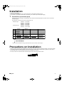
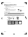
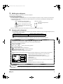
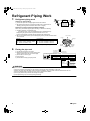
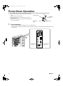
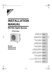
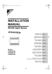
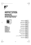
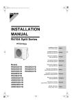
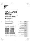
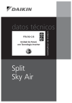
00_CV_3P164392-2J.fm Page 1 Wednesday, July 4, 2007 4:33 PM
INSTALLATION
MANUAL
R410A Split Series
Installation manual
R410A Split series
Installationsanleitung
Split-Baureihe R410A
Deutsch
Manuel d’installation
Série split R410A
Français
Montagehandleiding
R410A Split-systeem
Manual de instalación
Serie Split R410A
Manuale d’installazione
Serie Multiambienti R410A
Models
2MXS52E2V1B
3MXS52E2V1B
3AMX52E2V1B
2MXS52E3V1B
3MXS52E3V1B
3AMX52E3V1B
2AMX52E2V1B
3MKS50E2V1B
4MKS58E2V1B
2AMX52E3V1B
3MKS50E3V1B
4MKS58E3V1B
English
Εγχειρßδιο εγκατÜστασηò
διαιροýìενηò σειρÜò R410A
Manual de Instalação
Série split R410A
Рóêоводство по монтажó
Серия R410A с раздельной óстановêой
Montaj kýlavuzlarý
R410A Split serisi
Nederlands
Español
Italiano
ΕλληνικÜ
Portugues
Рóссêий
Türkçe
Daikin.TCF.015
74736-KRQ/EMC97-4957.
Daikin.TCF.015
74736-KRQ/EMC97-4957.
Daikin.TCF.015
74736-KRQ/EMC97-4957.
Daikin.TCF.015
74736-KRQ/EMC97-4957.
Daikin.TCF.015
74736-KRQ/EMC97-4957.
Daikin.TCF.015
74736-KRQ/EMC97-4957.
Daikin.TCF.015
74736-KRQ/EMC97-4957.
Daikin.TCF.015
74736-KRQ/EMC97-4957.
Daikin.TCF.015
74736-KRQ/EMC97-4957.
2MXS52E2V1B, 2AMX52E2V1B, 3MXS52E2V1B,
3MKS52E2V1B, 3AMX52E2V1B, 4MKS58E2V1B,
2MXS52E3V1B, 2AMX52E3V1B, 3MXS52E3V1B,
3MKS52E3V1B, 3AMX52E3V1B, 4MKS58E3V1B
DAIKIN INDUSTRIES, LTD.
Noboru Murata
Manager Quality Control Department
Shiga, 1st of Oct. 2007
Daikin.TCF.015
74736-KRQ/EMC97-4957
Daikin.TCF.015
74736-KRQ/EMC97-4957.
Daikin.TCF.015
74736-KRQ/EMC97-4957.
Daikin.TCF.015
74736-KRQ/EMC97-4957
Daikin.TCF.015
74736-KRQ/EMC97-4957.
Daikin.TCF.015
74736-KRQ/EMC97-4957.
74736-KRQ/EMC97-4957.
Daikin.TCF.015
Daikin.TCF.015
Daikin.TCF.015
74736-KRQ/EMC97-4957.
74736-KRQ/EMC97-4957.
Electromagnetic Compatibility 2004/108/EC
Low Voltage 2006/95/EC
Daikin.TCF.015
Daikin.TCF.015
Umeda Center Bldg., 2-4-12, Nakazaki-Nishi,
Kita-ku, Osaka, 530-8323 Japan
Daikin.TCF.015
74736-KRQ/EMC97-4957.
Daikin.TCF.015,
74736-KRQ/EMC97-4957.
Daikin.TCF.015
74736-KRQ/EMC97-4957.
Daikin.TCF.015
74736-KRQ/EMC97-4957
74736-KRQ/EMC97-4957.
74736-KRQ/EMC97-4957.
Daikin.TCF.015
74736-KRQ/EMC97-4957.
2SB63475-13M.fm Page 1 Friday, September 7, 2007 10:53 AM
2SB63475-13M
01_EN_3P164392-2J.fm Page 1 Tuesday, August 28, 2007 7:38 PM
Safety Precautions
• Read these Safety Precautions carefully to ensure correct installation.
• This manual classifies the precautions into WARNING and CAUTION.
Be sure to follow all the precautions below: they are all important for ensuring safety.
WARNING...............Failure to follow any of WARNING is likely to result in such grave consequences as death or serious injury.
CAUTION...............Failure to follow any of CAUTION may in some cases result in grave consequences.
• The following safety symbols are used throughout this manual:
Be sure to observe this instruction.
Be sure to establish an earth connection.
Never attempt.
• After completing installation, test the unit to check for installation errors. Give the user adequate instructions concerning the use
and cleaning of the unit according to the Operation Manual.
WARNING
• Installation should be left to the dealer or another professional.
Improper installation may cause water leakage, electrical shock, or fire.
• Install the air conditioner according to the instructions given in this manual.
Incomplete installation may cause water leakage, electrical shock, or fire.
• Be sure to use the supplied or specified installation parts.
Use of other parts may cause the unit to come to lose, water leakage, electrical shock, or fire.
• Install the air conditioner on a solid base that can support the unit’s weight.
An inadequate base or incomplete installation may cause injury in the event the unit falls off the base.
• Electrical work should be carried out in accordance with the installation manual and the national electrical wiring
rules or code of practice. Insufficient capacity or incomplete electrical work may cause electrical shock or fire.
• Be sure to use a dedicated power circuit. Never use a power supply shared by another appliance.
• For wiring, use a cable length enough to cover the entire distance with no connection.
Do not use an extension cord. Do not put other loads on the power supply, use a dedicated power circuit.
(Failure to do so may cause abnormal heat, electric shock or fire.)
• Use the specified types of wires for electrical connections between the indoor and outdoor units. Firmly clamp the interconnecting wires so their terminals receive no external stresses. Incomplete connections or clamping may cause terminal overheating or fire.
• After connecting interconnecting and supply wiring be sure to shape the cables so that they do not put undue force on the
electrical covers or panels. Install covers over the wires. Incomplete cover installation may cause terminal overheating, electrical shock, or fire.
• If any refrigerant has leaked out during the installation work, ventilate the room.
(The refrigerant produces a toxic gas if exposed to flames.)
• After all installation is complete, check to make sure that no refrigerant is leaking out.
(The refrigerant produces a toxic gas if exposed to flames.)
• When installing or relocating the system, be sure to keep the refrigerant circuit free from substances other than the
specified refrigerant (R410A), such as air.
(Any presence of air or other foreign substance in the refrigerant circuit causes an abnormal pressure rise or rupture, resulting in injury.)
• During pump-down, stop the compressor before removing the refrigerant piping.
If the compressor is still running and the stop valve is open during pump-down, air will be sucked in when the refrigerant piping is removed,
causing abnormal pressure in the freezer cycle which will lead to breakage and even injury.
• During installation, attach the refrigerant piping securely before running the compressor.
If the compressor is not attached and the stop valve is open during pump-down, air will be sucked in when the compressor is run, causing
abnormal pressure in the freezer cycle which will lead to breakage and even injury.
• Be sure to establish an earth. Do not earth the unit to a utility pipe, arrester, or telephone earth.
Incomplete earth may cause electrical shock, or fire. A high surge current from lightning or other sources may cause damage to the air conditioner.
• Be sure to install an earth leakage breaker. Failure to install an earth leakage breaker may result in electric shocks, or fire.
CAUTION
• Do not install the air conditioner in a place where there is danger of exposure to inflammable gas leakage.
If the gas leaks and builds up around the unit, it may catch fire.
• Establish drain piping according to the instructions of this manual. Inadequate piping may cause flooding.
• Tighten the flare nut according to the specified method such as with a torque wrench.
If the flare nut is tightened too hard, the flare nut may crack after a long time and cause refrigerant leakage.
• Make sure to provide for adequate measures in order to prevent that the outdoor unit be used as a shelter by small animals.
Small animals making contact with electrical parts can cause malfunctions, smoke or fire. Please instruct the customer to keep the area around
the unit clean.
1
■English
01_EN_3P164392-2J.fm Page 2 Tuesday, August 28, 2007 7:38 PM
Accessories
Accessories supplied with the outdoor unit:
(A) Installation Manual
1
(B) Drain plug
(C) Reducer assy
1
1
There is on the bottom packing case.
There is on the bottom packing case.
(2MXS52*, 2AMX52*, 3MXS52*, 3AMX52*, 4MKS58*)
(D) Screw bag
(For fixing electrical wire anchor bands)
(E) Refrigerant charge label
1
1
There is on the bottom packing case.
Precautions for Selecting the Location
1) Choose a place solid enough to bear the weight and vibration of the unit, where the operation noise will not be amplified.
2) Choose a location where the hot air discharged from the unit or the operation noise, will not cause a nuisance to the
neighbors of the user.
3) Avoid places near a bedroom and the like, so that the operation noise will cause no trouble.
4) There must be sufficient spaces for carrying the unit into and out of the site.
5) There must be sufficient space for air passage and no obstructions around the air inlet and the air outlet.
6) The site must be free from the possibility of flammable gas leakage in a nearby place.
Locate the unit so that the noise and the discharged hot air will not annoy the neighbors.
7) Install units, power cords and inter-unit cables at least 3 meter away from television and radio sets. This is to prevent
interference to images and sounds. (Noises may be heard even if they are more than 3 meter away depending on radio
wave conditions.)
8) In coastal areas or other places with salty atmosphere of sulfate gas, corrosion may shorten the life of the air conditioner.
9) Since drain flows out of the outdoor unit, do not place under the unit anything which must be kept away from moisture.
NOTE:
Cannot be installed hanging from ceiling or stacked.
CAUTION
When operating the air conditioner in a low outdoor ambient temperature, be sure to follow the instructions described below.
1) To prevent exposure to wind, install the outdoor unit with its suction side facing the wall.
2) Never install the outdoor unit at a site where the suction side may
be exposed directly to wind.
3) To prevent exposure to wind, it is recommended to install a baffle
plate on the air discharge side of the outdoor unit.
4) In heavy snowfall areas, select an installation site where the snow
will not affect the unit.
■English
Construct a large canopy.
Construct a pedestal.
Install the unit high enough off the
ground to prevent burying in snow.
2
01_EN_3P164392-2J.fm Page 3 Tuesday, August 28, 2007 7:38 PM
Indoor/Outdoor Unit
Installation Drawings
For installation of the indoor units, refer to the installation manual which was provided with the units.
(The diagram shows a wall-mounted indoor unit.)
CAUTION
1) Do not connect the embedded branch piping and the outdoor unit when only carrying out piping work without connecting the
indoor unit in order to add another indoor unit later.
Make sure no dirt or moisture gets into either side of the embedded branch piping.
See “7 Refrigerant piping work” on page 8 for details.
2) Heat pump type: It is impossible to connect the indoor unit for one room only. Be sure to connect at least 2 rooms.
Cooling only type: It is possible to connect the indoor unit for one room only.
Cut thermal insulation
pipe to an appropriate
length and wrap it with
tape, making sure that no
gap is left in the insulation
pipe’s cut line.
Caulk
pipe hole
gap
with putty.
Wrap the insulation
pipe with the finishing
tape from bottom to top.
Allow 30cm of work
space below the
ceiling surface.
25cm from wa
ll
If there is the danger of the unit falling
or overturning, fix the unit with
foundation bolts, or with wire or other
means.
Allow space for piping
and electrical servicing.
If the location does not have good
drainage, place the unit on a level
mounting base (or a plastic pedestal).
Install the outdoor unit in a level
position. Failure to do so may result in
water leakage or accumulation.
Stop valve cover
cm
h
ltbo s)
t
oo re
(F ent
c
33
(Foot
bo
lt-hole
ole
58cm
centre
s
)
Also insulate the connection on the outdoor unit.
Level mounting base
(available separately)
Clamping material
Insulation tube
Tape
Service lid
Use tape or insulating material on all connections
to prevent air from getting in between the copper
piping and the insulation tube.
Be sure to do this if the outdoor unit is installed
above.
3
■English
01_EN_3P164392-2J.fm Page 4 Tuesday, August 28, 2007 7:38 PM
Installation
• Install the unit horizontally.
• The unit may be installed directly on a concrete verandah or a solid place if drainage is good.
• If the vibration may possibly be transmitted to the building, use a vibration-proof rubber (field supply).
1.
Connections (connection port)
Install the indoor unit according to the table below, which shows the relationship between the class of indoor unit and the
corresponding port.
The total indoor unit class that can be connected to this unit:
Heat pump type:
Cooling only type:
2MXS52∗
2AMX52∗
Port
#
A
#
#
#
3MXS52∗
3AMX52∗
4MKS58∗
20 , 25 , 35 , 42
20 , 25 , 35 , 42
20 , 25 , 35 , 42
20 , 25 , 35 , 42
20 , 25 , 35 , 42
#
20 , 25 , 35 , 50
#
C
3MKS50∗
#
20 , 25 , 35 , 50
B
2AMX52∗ – Up to 8.5kW
2MXS52∗ – Up to 8.5kW
3MXS52∗ – Up to 9.0kW
3AMX52∗ – Up to 9.0kW
3MKS50∗ – Up to 9.5kW
4MKS58∗ – Up to 10.0kW
#
#
20 , 25 , 35 , 42
#
20 , 25 , 35 , 42 , 50
#
#
#
#
20 , 25 , 35 , 42 , 50
20 , 25 , 35 , 42
#
D
#
#
#
20 , 25 , 35 , 42 , 50
: Use a reducer to connect pipes.
: Use No. 2 and 4 reducers
▲
: Use No. 5 and 6 reducers
■
: Use No. 1 and 3 reducers
Refer to “How to Use Reducers” on page 10 for information on reducer numbers and their shapes.
#
Precautions on Installation
20
• Check the strength and level of the installation ground so that the unit will not cause any operating vibration or noise after installed.
• In accordance with the foundation drawing in fix the unit securely by means of the foundation bolts. (Prepare four sets of M8 or
M10 foundation bolts, nuts and washers each which are available on the market.)
• It is best to screw in the foundation bolts until their length are 20mm from the foundation surface.
■English
4
01_EN_3P164392-2J.fm Page 5 Tuesday, August 28, 2007 7:38 PM
Outdoor Unit Installation
Guideline
• Where a wall or other obstacle is in the path of outdoor unit’s intake or exhaust airflow, follow the installation guidelines below.
• For any of the below installation patterns, the wall height on the exhaust side should be 1200mm or less.
Walls facing two sides
Wall facing one side
More than 100
More than 350
More than 350
More
than 100
1200
or less
More than 50
More than 50
Top view
Side view
Walls facing three sides
More than 100
More than 350
More than 50
Top view
Unit: mm
Selecting a Location for Installation of
the Indoor Units
• The maximum allowable length of refrigerant piping, and the maximum allowable height difference between the outdoor and
indoor units, are listed below.
(The shorter the refrigerant piping, the better the performance. Connect so that the piping is as short as possible. Shortest allowable length per room is 3m.)
Outdoor unit capacity class
2MXS52, 2AMX52, 3MXS52, 3AMX52, 3MKS50, 4MKS58
Piping to each indoor unit
25m max.
Total length of piping between all units
50m max.
Indoor Unit
Outdoor Unit
Level
difference:
15m max.
Level
difference:
7.5m max.
(Heat pump
unit only)
If the outdoor unit is positioned higher than the
indoor units.
5
Level
difference:
15m max.
Level
difference:
7.5m max.
(Heat pump
unit only)
Outdoor Unit
Indoor Unit
If the outdoor unit is positioned otherwise.
(If lower than one or more indoor units)
■English
01_EN_3P164392-2J.fm Page 6 Tuesday, August 28, 2007 7:38 PM
Refrigerant Piping Work
1.
Installing outdoor unit
1) When installing the outdoor unit, refer to “Precautions for Selecting the Location” and the “Indoor/Outdoor Unit Installation
Drawings”.
2) If drain work is necessary, follow the procedures below.
2.
Drain work
1) Use drain plug for drainage.
2) If the drain port is covered by a mounting base or floor surface, place
additional foot bases of at least 30mm in height under the outdoor
unit’s feet.
3) In cold areas, do not use a drain hose with the outdoor unit.
(Otherwise, drain water may freeze, impairing heating performance.)
3.
Drain-water hole
Bottom frame
Drain plug
While pressing
Hose (available commercially,
inner dia. 16mm)
Refrigerant piping
CAUTION
1) Use the flare nut fixed to the main unit. (To prevent cracking of the flare nut by aged deterioration.)
2) To prevent gas leakage, apply refrigeration oil only to the inner surface of the flare. (Use refrigeration oil for R410A.)
3) Use torque wrenches when tightening the flare nuts to prevent damage to the flare nuts and gas leakage.
Align the centres of both flares and tighten the flare nuts 3 or 4 turns by hand. Then tighten them fully with the torque wrenches.
[Apply oil]
[Tighten]
Apply refrigeration oil to
Do not apply refrigeration
oil to the outer surface.
Torque wrench
the inner surface of the
flare.
Flare nut
Spanner
Piping union
Do not apply refrigeration
oil to the flare nut avoid
tightening with over torque.
Flare nut tightening torque
14.2-17.2N • m
Flare nut for φ6.4
(144-175kgf • cm)
32.7-39.9N • m
Flare nut for φ9.5
(333-407kgf • cm)
49.5-60.3N • m
Flare nut for φ12.7
(505-615kgf • cm)
61.8-75.4N • m
Flare nut for φ15.9
(630-769kgf • cm)
■English
Flare nut
Valve cap tightening
torque
Liquid pipe
26.5-32.3N • m
(270-330kgf • cm)
Gas pipe
48.1-59.7N • m
(490-610kgf • cm)
Service port cap
tightening torque
10.8-14.7N • m
(110-150kgf • cm)
6
01_EN_3P164392-2J.fm Page 7 Tuesday, August 28, 2007 7:38 PM
Refrigerant Piping Work
4.
Purging air and checking gas leakage
1) When piping work is completed, it is necessary to purge the air and check for gas leakage.
WARNING
1)
2)
3)
4)
Do not mix any substance other than the specified refrigerant (R410A) into the refrigeration cycle.
When refrigerant gas leaks occur, ventilate the room as soon and as much as possible.
R410A, as well as other refrigerants, should always be recovered and never be released directly into the environment.
Use a vacuum pump for R410A exclusively. Using the same vacuum pump for different refrigerants may damage the vacuum
pump or the unit.
• If using additional refrigerant, perform air purging from the refrigerant pipes and indoor unit using a vacuum pump, then charge
additional refrigerant.
• Use a hexagonal wrench (4mm) to operate the stop valve rod.
• All refrigerant pipe joints should be tightened with a torque wrench at the specified tightening torque.
1) Connect projection side of charging hose (which comes from gauge manifold) to gas stop valve’s service port.
2) Fully open gauge manifold’s low-pressure valve (Lo) and completely close its high-pressure valve (Hi).
(High-pressure valve subsequently requires no operation.)
3) Apply vacuum pumping. Check that the compound pressure gauge reads –0.1MPa (–76cmHg).
Evacuation for at least 1 hour is recommended.
4) Close gauge manifold’s low-pressure valve (Lo) and stop vacuum pump.
(Leave as is for 4-5 minutes and make sure the coupling meter needle does not go back.
If it does go back, this may indicate the presence of moisture or leaking from connecting parts. After inspecting all the connection and loosening then retightening the nuts, repeat steps 2-4.)
5) Remove covers from liquid stop valve and gas stop valve.
6) Turn the liquid stop valve’s rod 90 degrees counterclockwise with a hexagonal wrench to open valve.
Close it after 5 seconds, and check for gas leakage.
Using soapy water, check for gas leakage from indoor unit’s flare and outdoor unit’s flare and valve rods.
After the check is complete, wipe all soapy water off.
7) Disconnect charging hose from gas stop valve’s service port, then fully open liquid and gas stop valves.
(Do not attempt to turn valve rod beyond its stop.)
8) Tighten valve caps and service port caps for the liquid and gas stop valves with a torque wrench at the specified torques.
See “3 Refrigerant piping” on page 6 for details.
7
■English
01_EN_3P164392-2J.fm Page 8 Tuesday, August 28, 2007 7:38 PM
5.
Refilling the refrigerant
Check the type of refrigerant to be used on the machine nameplate.
Precautions when adding R410A
Fill from the liquid pipe in liquid form.
It is a mixed refrigerant, so adding it in gas form may cause the refrigerant composition to change, preventing normal operation.
1) Before filling, check whether the cylinder has a siphon attached or not. (It should have something like “liquid filling siphon
attached” displayed on it.)
Filling a cylinder with an attached siphon
Filling other cylinders
Stand the cylinder upright when filling.
Turn the cylinder upside-down
when filling.
There is a siphon pipe inside, so the
cylinder need not be upside-down to
fill with liquid.
2) Be sure to use the R410A tools to ensure pressure and to prevent foreign objects entering.
6.
Charging with refrigerant
1) If the total length of piping for all rooms exceeds the figure listed below, additionally charge with 20g of refrigerant (R410A)
for each additional meter of piping.
Outdoor capacity class
2MXS52, 2AMX52, 3MXS52, 3AMX52
Total length of piping for all rooms
30m
■ For cooling only
• Cooling only models (3MKS50, 4MKS58) are chargeless. There is no need to charge with refrigerant.
Important information regarding the refrigerant used
This product contains fluorinated greenhouse gases covered by the Kyoto Protocol.
Do not vent gases into the atmosphere.
Refrigerant type: R410A
GWP(1) value:
1975
(1) GWP
= global warming potential
Please fill in with indelible ink,
n 1 the factory refrigerant charge of the product,
n 2 the additional refrigerant amount charged in the field and
n 1 + 2 the total refrigerant charge
on the refrigerant charge label supplied with the product.
The filled out label must be adhered in the proximity of the product charging port (e.g. onto the inside of the stop valve
cover).
1 factory refrigerant charge of the product: see unit name plate
4
1
2 additional refrigerant amount charged in the field
(Refer to the above information for the quantity of refrigerant
replenishment.)
2
3 total refrigerant charge
4 Contains fluorinated greenhouse gases covered by the Kyoto Protocol
3
6
5
5 outdoor unit
6 refrigerant cylinder and manifold for charging
CAUTION
Even though the stop valve is fully closed, the refrigerant may slowly leak out; do not leave the flare nut removed for a long
period of time.
■English
8
01_EN_3P164392-2J.fm Page 9 Tuesday, August 28, 2007 7:38 PM
Refrigerant Piping Work
7.
Refrigerant piping work
Wall
Be sure to
place a cap.
Cautions on pipe handling
Rain
If no flare cap is
available, cover
the flare mouth
with tape to keep
dirt or water out.
1) Protect the open end of the pipe against dust and moisture.
2) All pipe bends should be as gentle as possible. Use a pipe bender for
bending. (Bending radius should be 30 to 40mm or larger.)
Selection of copper and heat insulation materials
When using commercial copper pipes and fittings, observe the following:
1) Insulation material: Polyethylene foam
Heat transfer rate: 0.041 to 0.052W/mK (0.035 to 0.045kcal/mh°C)
Refrigerant gas pipe’s surface temperature reaches 110°C max.
Choose heat insulation materials that will withstand this temperature.
2) Be sure to insulate both the gas and liquid piping and to provide insulation dimensions as below.
Inter-unit wiring
Gas pipe
Liquid pipe
Pipe size
Pipe insulation
O.D.: 6.4mm / Thickness: 0.8mm
O.D.: 9.5mm, 12.7mm / Thickness: 0.8mm
O.D.: 15.9mm / Thickness: 1.0mm
I.D.: 8–10mm / Thickness: 10mm min.
I.D.: 12–15mm / Thickness: 13mm min.
I.D.: 16–20mm / Thickness: 13mm min.
Gas pipe
insulation
3) Use separate thermal insulation pipes for gas and liquid refrigerant pipes.
Liquid pipe
insulation
Finishing tape
8.
Drain hose
Flaring the pipe end
1) Cut the pipe end with a pipe cutter.
2) Remove burrs with the cut surface facing downward so that the chips do not enter the pipe.
3) Put the flare nut on the pipe.
4) Flare the pipe.
5) Check that the flaring is properly made.
(Cut exactly at
right angles.)
Remove burrs
Flaring
Set exactly at the position shown below.
A
Die
A
Flare tool for R410A
Conventional flare tool
Clutch-type
Clutch-type (Rigid-type) Wing-nut type (Imperial-type)
0-0.5mm
1.0-1.5mm
1.5-2.0mm
Check
Flare’s inner
surface must
be flaw-free.
The pipe end must
be evenly flared in
a perfect circle.
Make sure that the
flare nut is fitted.
WARNING
1)
2)
3)
4)
5)
6)
9
Do not use mineral oil on flared part.
Prevent mineral oil from getting into the system as this would reduce the lifetime of the units.
Never use piping which has been used for previous installations. Only use parts which are delivered with the unit.
Do never install a drier to this R410A unit in order to guarantee its lifetime.
The drying material may dissolve and damage the system.
Incomplete flaring may cause refrigerant gas leakage.
■English
01_EN_3P164392-2J.fm Page 10 Tuesday, August 28, 2007 7:38 PM
How to Use Reducers
No.1
φ15.9
→ φ12.7
No.2
φ12.7
→ φ9.5
Gasket (1)
No.3
φ15.9
→ φ12.7
No.4
φ12.7
→ φ9.5
No.5
φ15.9
→ φ9.5
Gasket (2)
No.6
φ15.9
→ φ9.5
Reduce and gasket
Use the reducers supplied with the unit as described below.
1) Connecting a pipe of φ12.7 to a gas pipe connection port for φ15.9:
No. 1
Be sure to attach
the gasket.
Inter-unit piping
No. 3
Flare nut (for φ15.9)
Connection port
of outdoor unit
2) Connecting a pipe of φ9.5 to a gas pipe connection port for φ15.9:
Flare nut (for φ9.5)
No. 6
No. 5
Be sure to attach
the gasket.
3) Connecting a pipe of φ9.5 to a gas pipe connection port for φ12.7:
No. 2
No. 4
Flare nut (for φ12.7)
Be sure to attach
the gasket.
• When using the reducer packing shown above, be careful not to overtighten the nut, or the smaller pipe may be damaged. (about 2/3 - 1
the normal torque)
• Apply a coat of refrigeration oil to the threaded connection port of the
outdoor unit where the flare nut comes in.
• Use an appropriate wrench to avoid damaging the connection thread
by overtightening the flare nut.
■English
Flare nut tightening torque
Flare nut for φ9.5
32.7–39.9N·m
(333–407kgf·cm)
Flare nut for φ12.7
49.5–60.3N·m
(505–615kgf·cm)
Flare nut for φ15.9
61.8–75.4N·m
(630–769kgf·cm)
10
01_EN_3P164392-2J.fm Page 11 Tuesday, August 28, 2007 7:38 PM
Pump Down Operation
In order to protect the environment, be sure to pump down when relocating or disposing of the unit.
1) Remove the valve cap from liquid stop valve and gas stop
valve.
2) Carry out forced cooling operation.
3) After five to ten minutes, close the liquid stop valve with a
hexagonal wrench.
4) After two to three minutes, close the gas stop valve and stop
forced cooling operation.
1.
Gas stop valve
Close
Hexagonal
wrench
Liquid stop
valve
Valve cap
Forced operation
1) Turn the Operation Mode switch (SW2) to “COOL”. (Heat pump only)
2) Press the Forced Operation switch (SW1) to begin forced cooling. Press the Forced Operation switch (SW1) again to stop
forced cooling.
Service PC-board
Operation Mode
switch (SW2)
11
Forced Operation
switch (SW1)
■English
01_EN_3P164392-2J.fm Page 12 Tuesday, August 28, 2007 7:38 PM
Wiring
WARNING
1) Do not use tapped wires, strand wires, extensioncords, or starburst connections, as they may cause overheating, electrical shock, or fire.
2) Do not use locally purchased electrical parts inside the product. (Do not branch the power for the drain pump, etc., from the
terminal block.) Doing so may cause electric shock or fire.
3) Be sure to install an earth leakage breaker. (One that can handle higher harmonics.)
(This unit uses an inverter, which means that it must be used an earth leakage breaker capable handling harmonics in order to
prevent malfunctioning of the earth leakage breaker itself.)
4) Use an all-pole disconnection type breaker with at least 3 mm between the contact point gaps.
• Do not turn ON the safety breaker until all work is completed.
1) Strip the insulation from the wire (20mm).
2) Connect the connection wires between the
indoor and outdoor units so that the terminal
numbers match. Tighten the terminal screws
securely. We recommend a flathead screwdriver be used to tighten the screws. The
screws are packed with the terminal board.
Room
A
Room
B
Room
C
Room
D
Outdoor unit
Be sure to use the dedicated circuits.
Earth leakage
circuit breaker
Safety breaker
50Hz
220-240V
To room D
Indoor unit
To room C
H05RN
Room A
To room B
If the length of a connection wire is
10m or more, use φ2.0mm wire.
CAUTION
When connecting the connection wires to the
terminal board using a single core wire, be sure
to perform curling.
Problems with the work may cause heat and fires.
• Ground terminal installation
Use the following method when installing the round
crimp-style terminal.
Good
Screw
Screw
Round crimpstyle terminal
Flat washer
Flat washer
Round crimpstyle terminal
L
Shape the wires so that
there is no lifting of the
service hatch or other
structural parts.
N
Use the specified wires and
connect them securely.
Secure the branch wiring firmly using the 4
included screws, as shown in the figure.
Secure firmly, making sure no outside pressure is
exerted on the terminals.
Wrong
3) Pull the wire and make sure that it does not disconnect. Then fix the wire in place with a wire stop.
■ Earth
This air conditioner must be earthed.
For earthing, follow the applicable local standard for electrical installations.
■English
12
01_EN_3P164392-2J.fm Page 13 Tuesday, August 28, 2007 7:38 PM
Priority Room Setting
• To use priority room setting, initial settings must be made when the unit is installed. Explain the priority room setting, as described
below, to the customer, and confirm whether or not the customer wants to use priority room setting.
Setting it in the guest and living rooms is convenient.
1.
About the priority room setting function
Service PC-board
The indoor unit for which priority room setting is applied takes priority in the
following cases.
1-1. Operation mode priority
The operation mode of the indoor unit which is set for priority room setting
takes priority. If the set indoor unit is operating, all other indoor units do not
operate and enter standby mode, according to the operation mode of the set
indoor unit.
Priority Room
Setting switch (SW4)
1-2. Priority during high-power operation
If the indoor unit which is set for priority room setting is operating at high
power, the capabilities of other indoor units will be somewhat reduced.
Power supply gives priority to the indoor unit which is set for priority room
setting.
1-3. Quiet operation priority
Setting the indoor unit to quiet operation will make the outdoor unit
run quietly.
Setting procedure
Slide the switch to the ON side for the switch that corresponds to the piping connected to the indoor unit to be set. (In the figure below, it is room A.)
Once the settings are complete, reset the power.
Be sure to only set one room
13
■English
01_EN_3P164392-2J.fm Page 14 Tuesday, August 28, 2007 7:38 PM
Night Quiet Mode Setting
• If night quiet mode is to be used, initial settings must be made when the unit is
installed.
Explain night quiet mode, as described below, to the customer, and confirm
whether or not the customer wants to use
night quiet mode.
Service PC-board
About night quiet mode
The night quiet mode function reduces operating noise of the outdoor unit at nighttime. This function is useful if the customer is worried about the effects of the operating noise on the neighbors.
However, if night quiet mode is running, cooling/heating capacity will be saved.
Setting procedure
Remove the SW5 jumper switch.
Once the settings are complete, reset the power.
Night Quiet Mode
setting switch (SW5)
NOTE:
Install the removed jumper switch as described below. This switch will be needed
to later disable this setting.
Jumper switch
After removing
COOL/ HEAT Mode Lock <S15>
(Heat Pump Units Only)
• Use the S15 connector to set the unit to only cool or heat.
Setting to only heat (H): short-circuit pins 1 and 3 of the connector <S15>
Setting to only cool (C): short-circuit pins 3 and 5 of the connector <S15>
The following specifications apply to the connector housing and pins.
JST products
Housing:
VHR-5N
Pin:
SVH-21T-1,1
Note that forced operation is also possible in COOL/HEAT mode.
COOL mode (C)
HEAT mode (H)
5<C>3<H>1
5 ! 5
5
5#
5
PCB
5
Allow view
■English
14
01_EN_3P164392-2J.fm Page 15 Tuesday, August 28, 2007 7:38 PM
Test Run and Final Check
• Before starting the test run, measure the voltage at the primary side of the safety breaker. Check that it is 220-240V.
• Check that all liquid and gas stop valves are fully open.
• Check that piping and wiring all match. The wiring error check can be conveniently used for underground wiring and other wiring
that cannot be directly checked.
1.
Wiring error check
• This product is capable of automatic correction of wiring error.
• Press the “wiring error check switch” on the outdoor unit service monitor
print board. However, the wiring error check switch will not function for
one minute after the safety breaker is turned on, or depending on the
outside air conditions (See NOTE 2.). Approximately 10–15 minutes
after the switch is pressed, the errors in the connection wiring will be
corrected.
Service PC-board
Wiring error
check switch
(SW3)
The service monitor LEDs indicate whether or not correction is
possible, as shown in the table below. For details about how to read the
LED display, refer to the service guide.
If self-correction is not possible, check the indoor unit wiring and piping
in the usual manner.
LED
Status
1
2
3
4
Message
All Flashing
Automatic correction impossible
Flashing One after another
Automatic correction completed
(One or more of LEDs 1 to 4 are ON) Abnormal stop [NOTE. 4]
Wiring correct example
Terminal block
∗ The figure at left shows branch wiring.
From Room C
to the “kitchen”
From Room B
From Room D
From Room A
to the “living room” to the “children’s room” to the “bedroom”
Wiring error check
LED lighting sequence after a wiring correction.
Order of LED flashing: 2 ➝ 1 ➝ 3 ➝ 4
NOTE:
1) For two rooms, LED 3 and 4 are not displayed, and for three rooms, LED 4 is not displayed.
2) If the outside air temperature is 5°C or less , the wiring error check function will not operate.
3) After wiring error check operation is completed, LED indication will continue until ordinary operation starts.
This is normal.
4) Follow the product diagnosis procedures. (Check the nameplate on the underside of the stop valve.)
15
■English
01_EN_3P164392-2J.fm Page 16 Tuesday, August 28, 2007 7:38 PM
2.
Test run and final check
1) To test cooling, set for the lowest temperature. To test heating, set for the highest temperature. (Depending on the room
temperature, only heating or cooling (but not both) may be possible.)
2) After the unit is stopped, it will not start again (heating or cooling) for approximately 3 minutes.
3) During the test run, first check the operation of each unit individually. Then also check the simultaneous operation of
all indoor units.
Check both heating and cooling operation.
4) After running the unit for approximately 20 minutes, measure the temperatures at the indoor unit inlet and outlet. If the
measurements are above the values shown in the table below, then they are normal.
Temperature difference
between inlet and outlet
Cooling
Heating
Approx. 8°C
Approx. 20°C
(When running in one room)
5) During cooling operation, frost may form on the gas stop valve or other parts. This is normal.
6) Operate the indoor units in accordance with the included operation manual. Check that they operate normally.
3.
Items to check
Check item
Consequences of trouble
Are the indoor units installed securely?
Falling, vibration, noise
Has an inspection been made to check for gas leakage?
No cooling, no heating
Has complete thermal insulation been done (gas pipes, liquid
pipes, indoor portions of the drain hose extension)?
Water leakage
Is the drainage secure?
Water leakage
Are the ground wire connections secure?
Danger in the event of a ground fault
Are the electric wires connected correctly?
No cooling, no heating
Is the wiring in accordance with the specifications?
Operation failure, burning
Are the inlets/outlets of the indoor and outdoor units free of any
obstructions? Are the stop valves open?
No cooling, no heating
Do the marks match (room A, room B) on the wiring and piping
for each indoor unit?
No cooling, no heating
Is the priority room setting set for 2 or more rooms?
The priority room setting will not function.
Check
■ ATTENTION
1) Have the customer actually operate the unit while looking at the manual included with the indoor unit. Instruct the customer
how to operate the unit correctly (particularly cleaning of the air filters, operation procedures, and temperature adjustment).
2) Even when the air conditioner is not operating, it consumes some electric power. If the customer is not going to use the unit
soon after it is installed, turn OFF the breaker to avoid wasting electricity.
3) If additional refrigerant has been charged because of long piping, list the amount added on the nameplate on the reverse side
of the stop valve cover.
■English
16
00_CV_3P164392-2J.fm Page 2 Wednesday, July 4, 2007 4:33 PM
Two-dimensional bar code is a code
for manufacturing.
3P164392-2J M05B110E
(0710) HT