1
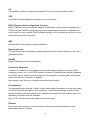
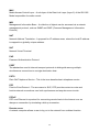
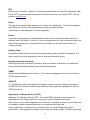
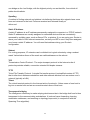
VDSL 2 Router VC-230 User's Manual 1 Copyright Copyright© 2009 by PLANET Technology Corp. All rights reserved. No part of this publication may be reproduced, transmitted, transcribed, stored in a retrieval system, or translated into any language or computer language, in any form or by any means, electronic, mechanical, magnetic, optical, chemical, manual or otherwise, without the prior written permission of PLANET. PLANET makes no representations or warranties, either expressed or implied, with respect to the contents hereof and specifically disclaims any warranties, merchantability or fitness for any particular purpose. Any software described in this manual is sold or licensed "as is". Should the programs prove defective following their purchase, the buyer (and not this company, its distributor, or its dealer) assumes the entire cost of all necessary servicing, repair, and any incidental or consequential damages resulting from any defect in the software. Further, this company reserves the right to revise this publication and to make changes from time to time in the contents hereof without obligation to notify any person of such revision or changes. All brand and product names mentioned in this manual are trademarks and/or registered trademarks of their respective holders. Federal Communication Commission Interference Statement This equipment has been tested and found to comply with the limits for a Class B digital device, pursuant to Part 15 of FCC Rules. These limits are designed to provide reasonable protection against harmful interference in a residential installation. This equipment generates, uses, and can radiate radio frequency energy and, if not installed and used in accordance with the instructions, may cause harmful interference to radio communications. However, there is no guarantee that interference will not occur in a particular installation. If this equipment does cause harmful interference to radio or television reception, which can be determined by turning the equipment off and on, the user is encouraged to try to correct the interference by one or more of the following measures: 1. Reorient or relocate the receiving antenna. 2. Increase the separation between the equipment and receiver. 3. Connect the equipment into an outlet on a circuit different from that to which the receiver is connected. 4. Consult the dealer or an experienced radio technician for help. FCC Caution To assure continued compliance (example-use only shielded interface cables when connecting to computer or peripheral devices). Any changes or modifications not expressly approved by the party responsible for compliance could void the user’s authority to operate the equipment. This device complies with Part 15 of the FCC Rules. Operation is subject to the Following two conditions: (1) This device may not cause harmful interference, and (2) this Device must accept any interference received, including interference that may cause undesired operation. 2 Federal Communication Commission (FCC) Radiation Exposure Statement This equipment complies with FCC radiation exposure set forth for an uncontrolled environment. In order to avoid the possibility of exceeding the FCC radio frequency exposure limits, human proximity to the antenna shall not be less than 20 cm (8 inches) during normal operation. CE mark Warning This is a class B device, in a domestic environment; this product may cause radio interference, in which case the user may be required to take adequate measures. R&TTE Compliance Statement This equipment complies with all the requirements of DIRECTIVE 1999/5/EC OF THE EUROPEAN PARLIAMENT AND THE COUNCIL OF 9 March 1999 on radio equipment and telecommunication terminal Equipment and the mutual recognition of their conformity (R&TTE) The R&TTE Directive repeals and replaces in the directive 98/13/EEC (Telecommunications Terminal Equipment and Satellite Earth Station Equipment) As of April 8, 2000. WEEE Regulation To avoid the potential effects on the environment and human health as a result of the presence of hazardous substances in electrical and electronic equipment, end users of electrical and electronic equipment should understand the meaning of the crossed-out wheeled bin symbol. Do not dispose of WEEE as unsorted municipal waste and have to collect such WEEE separately. Safety This equipment is designed with the utmost care for the safety of those who install and use it. However, special attention must be paid to the dangers of electric shock and static electricity when working with electrical equipment. All guidelines of this and of the computer manufacture must therefore be allowed at all times to ensure the safe use of the equipment. Revision User’s Manual for VDSL 2 Router Model: VC-230 Rev: 1.0 (Oct. 2009) Part No. EM-VC230_v1 3 Table of Contents 1. INTRODUCTION ........................................................................................................................................................ 6 1.1 Feature ................................................................................................................................ 6 1.2 Package Contents .............................................................................................................. 7 1.3 Physical Details .................................................................................................................. 8 2. INSTALLATION.......................................................................................................................................................... 9 2.1 System Requirement.......................................................................................................... 9 2.2 Hardware Installation ......................................................................................................... 9 2.3 Configuring the Network Properties............................................................................... 10 2.4 Configuring with Web Browser ....................................................................................... 16 2.5 Applications ...................................................................................................................... 18 2.5.1 Bridge Mode for LAN-to-LAN connection ............................................................................................. 18 2.5.2 Router Mode for Internet connection....................................................................................................... 22 2.5.3 Router Mode for PPPoE with IP Sharing................................................................................................. 26 3. WEB CONFIGURATION MANAGEMENT .......................................................................................................... 28 3.1 Operation Mode ................................................................................................................ 29 3.2 Internet Settings ............................................................................................................... 30 3.2.1 WAN........................................................................................................................................................ 30 ¾ STATIC (FIXED IP) ...................................................................................................................... 30 ¾ DHCP (AUTO CONFIG)............................................................................................................... 31 ¾ PPPOE (ADSL)............................................................................................................................... 32 ¾ L2TP ................................................................................................................................................ 33 ¾ PPTP ................................................................................................................................................ 35 3.2.2 LAN ......................................................................................................................................................... 36 3.2.3 DHCP clients ........................................................................................................................................... 37 3.2.4 Advanced Routing ................................................................................................................................... 38 3.2.5 QoS .......................................................................................................................................................... 39 3.3 Firewall .............................................................................................................................. 40 3.3.1 MAC/IP/Port Filtering ............................................................................................................................. 40 3.3.2 Port Forwarding (Virtual Server)............................................................................................................. 42 3.3.3 DMZ ........................................................................................................................................................ 43 3.3.4 System Security Settings.......................................................................................................................... 44 3.3.5 Content Filtering ...................................................................................................................................... 45 3.4 VDSL .................................................................................................................................. 46 4 3.4.1 VDSL Status ............................................................................................................................................ 46 3.4.2 VDSL Configuration................................................................................................................................ 47 3.5 Administration .................................................................................................................. 50 3.5.1 Management ............................................................................................................................................ 50 3.5.2 Upload Firmware ..................................................................................................................................... 51 3.5.3 Setting Management ................................................................................................................................ 52 3.5.4 Reboot...................................................................................................................................................... 53 3.5.5 Status........................................................................................................................................................ 53 3.5.6 Statistics................................................................................................................................................... 54 3.5.7 System Log .............................................................................................................................................. 55 APPENDIX A: PERFORMANCE OF VC-230 PROFILES....................................................................................... 56 APPENDIX B: GLOSSARY.......................................................................................................................................... 57 5 1. Introduction The PLANET VDSL2 Router, VC-230 is based on two core networking technologies: Ethernet and VDSL2 (Very High Speed Digital Subscriber Line 2). This technology offers the absolute fastest data transmission speeds over existing copper telephone lines without the need for rewiring. The PLANET VC-230 can provide very high performance access to Internet, both downstream and upstream up to 100Mbps. The VC-230 complies with ITU-T G993.2 standard, and provides two modes for applications – Bridge and Router. With 4-port 10/100 Ethernet switch, it provide data deliver and receive in local network, so that it is the best solution for small enterprise and residence. There are two selectable operating modes of VC-230, CO and CPE. The CO or CPE mode can be adjusted by WEB UI and users can connect two VC-230 for Point-to-Point Application, data transmission between two networks over existing copper telephone lines. Via the user-friendly management interface, VC-230 can be managed easily by computer running standard web browsers. Furthermore, the VC-230 not only provides basic router’s functions, such as DHCP server, Virtual Server, DMZ, QoS, and UPnP, but also provides the fully firewall functions, such as Network Address Translation (NAT), IP/Port/MAC Filtering and Content Filtering. It serves as an Internet firewall to protect your network from being accessed by outside users. 1.1 Feature Internet Access Features Shared Internet Access: All users on the LAN can access the Internet through the VC-230 using only a single external IP Address. The local (invalid) IP Addresses are hidden from external sources. This process is called NAT (Network Address Translation). Built-in VDSL2 Modem: The VC-230 provides VDSL2 modem, and supports all common VDSL2 connections. Multiple WAN Connection: On the Internet (WAN port) connection, the VC-230 supports Dynamic IP Address (IP Address is allocated on connection), Fixed IP Address, PPPoE, PPTP and L2TP. CO and CPE type Support: The VC-230 provides the Peer-to-Peer connection. Users can select the CO and CPE mode manually. Bridge and Router Application: The VC-230 supports two application modes. Currently, it comes pre-configured with routing mode. Note that, routing mode and bridging mode cannot be used simultaneously. 6 Advanced Internet Functions Virtual Servers: This feature allows Internet users to access Internet servers on your LAN. The required setup is quick and easy. Firewall: Universal Plug and Play (UPnP): UPnP allows automatic discovery and configuration of the Broadband Router. UPnP is supported by Windows ME, XP, or later. Selectable VDSL2 Profiles: The VC-230 supports common VDSL2 profiles (30a, 17a, 12a, 12b, 8a, 8b, 8c, 8d) for selectable. Users can choose different VDSL2 profiles based on their requirements. User Friendly Interface: DMZ Support: The VC-230 can translate public IP addresses to private IP address to allow unrestricted 2-way communication with Servers or individual users on the Internet. This provides the most flexibility to run programs, which could be incompatible in NAT environment. Bridge and Router Application: The VC-230 supports two application modes. Currently, it comes pre-configured with routing mode. Note that, routing mode and bridging mode cannot be used simultaneously. RIP1/2 Routing: VPN Pass through Support: PCs with VPN (Virtual Private Networking) software are transparently supported - no configuration is required. Supports simple firewall with NAT technology. VC-230 can be managed and controlled through Web UI. It supports RIPv1/2 routing protocol for routing capability. LAN Features 4-Port Switch: The VC-230 incorporates a 4-port 10/100Base-TX switching hub, making it easy to create or extend your LAN. DHCP Server Support: Dynamic Host Configuration Protocol provides a dynamic IP address to PCs and other devices upon request. The VC-230 can act as a DHCP Server for devices on your local LAN. 1.2 Package Contents VC-230 Unit x 1 Power Adapter x 1 Quick Installation Guide x 1 User’s Manual CD x 1 RJ-45 cable x 1 RJ-11cable x 1 7 1.3 Physical Details Front Panel of VC-230 Front Panel LED definition LED State PWR DSL ON When the router is powered on, and in ready state. OFF When the router is powered off. Flashing Router is trying to establish a VDSL2 connection to VDSL2 device or telecom’s network. ON LAN1-4 Description The VDSL2 connection connected successfully. Flashing Data is being transmitted or received via the corresponding LAN port. ON The port is up. Rear Panel Rear Panel Port and Button Definition Connector Description POWER Power connector with 12V DC 1 A RESET Press more than 3 seconds for reset to factory default setting. LAN (1-4) Router is successfully connected to a device through the corresponding port (1, 2, 3, or 4). If the LED light of LNK/ACT is flashing, the Router is actively sending or receiving data over that port. PHONE Built-in splitter for POTS connection. VDSL2 The RJ-11 connector allows data communication between the router and the VDSL2 network through a twisted-pair phone wire 8 2. Installation This chapter offers information about installing your router. If you are not familiar with the hardware or software parameters presented here, please consult your service provider for the values needed. 2.1 System Requirement 1. Personal computer (PC) 2. Pentium III 266 MHz processor or higher 3. 128 MB RAM minimum 4. 20 MB of free disk space minimum 5. RJ45 Ethernet Port 2.2 Hardware Installation Please connect the device to you computer as follow: z Connect your telephone to the “Phone” Port via RJ-11 telephone line. z Use another telephone cable to connect “VDSL” port of the router. And connect the other side to your CO side devices, such as VDSL 2 DSLAM, VDSL 2 Switch, or another VC-230 with CO mode. z Use Ethernet cable to connect “LAN” port of the modem and “LAN” port of your computer. Figure 1 VC-230 connection diagram 9 2.3 Configuring the Network Properties Configuring PC in Windows Vista 1. Go to Start / Control Panel / Network and Internet / Network and Sharing Center. Double-click on Network Connections. 2. Double-click Local Area Connection. 3. In the Local Area Connection Status window, click Properties. 10 4. Select Internet Protocol Version 4 (TCP/IPv4) and click Properties. 5. Select the Obtain an IP address automatically and the Obtain DNS server address automatically radio buttons. 6. Click OK to finish the configuration. 11 Configuring PC in Windows XP 1. Go to Start / Control Panel (in Classic View). In the Control Panel, double-click on Network Connections 2. Double-click Local Area Connection. 3. In the Local Area Connection Status window, click Properties. 12 4. Select Internet Protocol (TCP/IP) and click Properties. 5. Select the Obtain an IP address automatically and the Obtain DNS server address automatically radio buttons. 6. Click OK to finish the configuration. 13 Configuring PC in Windows 2000 1. 2. Go to Start / Settings / Control Panel. In the Control Panel, double-click on Network and Dial-up Connections. Double-click Local Area Connection. 3. In the Local Area Connection Status window click Properties. 4. Select Internet Protocol (TCP/IP) and click Properties. 5. Select the Obtain an IP address automatically and the Obtain DNS server address automatically radio buttons. 6. Click OK to finish the configuration. 14 Configuring PC in Windows 98/Me 1. Go to Start / Settings / Control Panel. In the Control Panel, double-click on Network and choose the Configuration tab. 2. Select TCP/IP Æ NE2000 Compatible, or the name of your Network Interface Card (NIC) in your PC. 3. Select the Obtain an IP address automatically radio button. 4. Then select the DNS Configuration tab. 5. Select the Disable DNS radio button and click OK to finish the configuration. 15 2.4 Configuring with Web Browser It is advisable to change the administrator password to safeguard the security of your network. To configure the router, open your browser, type “http: //192.168.1.1” into the address bar and click “Go” to get to the login page. Save this address in your Favorites for future reference. At the User name and Password prompt, type your proper user name and password to login. The default user name / password are “admin / admin”. You can change these later if you wish. Click “OK”. 16 If the user name and password are correct, you will login VC-230 successfully and see the status page. Now you can configure the VC-230 for your needs. 17 2.5 Applications The VC-230 supports two modes, users can select Router or Bridge mode for your applications. Please check as below examples for more details. 2.5.1 Bridge Mode for LAN-to-LAN connection Web UI Configuration For VC-230 CO side Step 1: Select the Bridge mode. 18 Step 2: Setup your LAN IP, for example, we use the 192.168.1.1 / 255.255.255.0 and enable DHCP server for VC-230 CO side. Step 3: Modify your VDSL mode, default is CPE mode. Select the VDSL CO mode. 19 For VC-230 CPE side Step 1: Select the Bridge mode. Step 2: Setup your LAN IP, for example, we use the 192.168.1.2 / 255.255.255.0 and disable DHCP server for VC-230 CPE side. 20 Step 3: Modify your VDSL mode, default is CPE mode. After setting, the DSL line will try to establish the connection between two VC-230. you can check the DSL LED, when the LED stop flashing and steady, the VC-230 will establish a connection and the PC1 and PC2 can access to each other. 21 2.5.2 Router Mode for Internet connection Web UI Configuration For VC-230 CO side Step 1: Select the Bridge mode. 22 Step 2: Setup your LAN IP, for example, we use the 192.168.1.1 / 255.255.255.0 for VC-230 CO side. Step 3: Modify your VDSL mode, default is CPE mode. Select the VDSL CO mode. 23 For VC-230 CPE side Step 1: Select the Router mode and enable the NAT. Step 2: Configure your WAN settings, type your WAN IP, Mask, Gateway and DNS. 24 Step 3: Modify your VDSL mode, default is CPE mode. After setting, the DSL line will try to establish the connection between two VC-230. you can check the DSL LED, when the LED stop flashing and steady, the VC-230 will establish a connection and the PC can access to Internet through VDSL connection. 25 2.5.3 Router Mode for PPPoE with IP Sharing Web UI Configuration Step 1: Select the Router mode and enable the NAT. 26 Step 2: Configure your WAN settings, select the PPPoE connection type and enter your PPPoE user name and password. Step 3: When the PPPoE connection is OK, the PC will access to Internet through PPPoE connection. 27 3. Web Configuration Management Determine your connection settings Before you configure the router, you need to know the connection information supplied by your service provider. Connecting the VDSL 2 Router to your network Unlike a simple hub or switch, the setup of the VDSL Router consists of more than simply plugging everything together. Because the Router acts as a DHCP server, you will have to set some values within the Router, and also configure your networked PCs to accept the IP Addresses the Router chooses to assign them. Generally there are several different operating modes for your applications. And you can know which mode is necessary for your system from ISP. These modes are router, bridge, and PPPoE+NAT. Configuring with Web Browser It is advisable to change the administrator password to safeguard the security of your network. To configure the router, open your browser, type “http: //192.168.1.1” into the address bar and click “Go” to get to the login page. Save this address in your Favorites for future reference. At the User name prompt, type “admin”. And the Password prompt, type “admin”. You can change these later if you wish. Click “OK” to login the router and you can start to configure it now. 28 3.1 Operation Mode The VC-230 supports two operation modes – Router and Bridge. Currently, it comes pre-configured with routing mode. Note that, routing mode and bridging mode cannot be used simultaneously. For Bridge mode, all interfaces are bridged into a single bridge interface. For Router mode, the VDSL port is treated as WAN port. The other interfaces are bridged together and are treated as LAN ports. If you select Bridge operation mode, WAN configuration in Internet Settings are not available. (Firewall functions on the left page are not available.) After finishing setting, click Apply to save the settings and make the new configuration take effect. Click Cancel to close without saving. 29 3.2 Internet Settings 3.2.1 WAN The WAN Settings screen allows you to specify the type of Internet connection. The WAN settings offer the following selections for the router’s WAN port, STATIC (fixed IP), DHCP (Auto config), PPPoE, L2TP, and PPTP. ¾ STATIC (FIXED IP) Select STATIC (fixed IP) in the WAN Connection Type drop-down list and the following page appears. 30 Static Mode IP Address: Enter the IP address of WAN port. Subnet Mask: Enter IP subnet mask of WAN port. Default Gateway: Enter the default gateway address of WAN port. Primary DNS Server: Primary DNS Server f of WAN port. Secondary DNS Server: Secondary DNS Server of WAN port. MAC Clone MAC Clone provides WAN to connect to a MAC address. Enabled: Enable or disable MAC clone. After finishing setting, click Apply to save the settings and make the new configuration take effect. Click Cancel to close without saving. ¾ DHCP (AUTO CONFIG) Select DHCP (Auto config) in the WAN Connection Type drop-down list and the following page appears. If the WAN connection type is set to DHCP, the device automatically obtains the IP address, gateway and DNS address from the DHCP server on WAN interface. MAC Clone MAC Clone provides WAN to connect to a MAC address. Enabled: Enable or disable MAC clone. After finishing setting, click Apply to save the settings and make the new configuration take effect. Click Cancel to close without saving. 31 ¾ PPPOE (ADSL) Select PPPoE (ADSL) in the WAN Connection Type drop-down list and the following page appears. If the WAN connection type is set to PPPoE, you can configure the following parameters to PPPoE dial up. PPPoE Mode User Name: User name of PPPoE account Password: Password of PPPoE account Verify Password: Enter the password of PPPoE account again. Operation Mode: It provides two types of operation modes. Keep Alive means keeping on-line mode. You can set the redial period in the field. When the redial period expires, Router will execute dial-up again to keep online. On Demand means executing dial-up on demand. Within the preset idle time, if Router does not detect the flow of the user continuously, Router automatically stops the PPPOE connection. Once it detects the flow (e.g., accessing a webpage), the router restarts the PPPOE dial-up. MAC Clone Enabled: Enable or disable. After finishing setting, click Apply to save the settings and make the new configuration take effect. Click Cancel to close without saving. 32 ¾ L2TP Select L2TP in the WAN Connection Type drop-down list and the following page appears. There are two address modes: Static and Dynamic. 1. If you select Static in the Address Mode field, the page shown in the following figure appears. 2. If you select Dynamic in the Address Mode field, the page shown in the following figure appears. 33 L2TP Mode Server IP: Address of L2TP server. User Name: The user name of L2TP account. Password: The password of L2TP account. IP Address: IP address of WAN port. Subnet Mask: Subnet mask of WAN port. Default Gateway: The default gate way of WAN port. Operation Mode: It provides two types of operation modes. Keep Alive means keeping on-line mode. You can set the redial period in the field. When the redial period expires, Router will execute dial-up again to keep online. On Demand means executing dial-up on demand. Within the preset idle time, if Router does not detect the flow of the user continuously, Router automatically stops the PPPOE connection. Once it detects the flow (e.g., accessing a webpage), the router restarts the PPPOE dial-up. MAC Clone Enabled: Enable or disable. After finishing setting, click Apply to save the settings and make the new configuration take effect. Click Cancel to close without saving. 34 ¾ PPTP Select PPTP in the WAN Connection Type drop-down list and the following page appears. There are two address modes: Static and Dynamic. PPTP Mode Server IP: Address of PPTP server. User Name: The user name of PPTP account. Password: The password of PPTP account. IP Address: IP address of WAN port. Subnet Mask: Subnet mask of WAN port. Default Gateway: The default gate way of WAN port. Operation Mode: It provides two types of operation modes. Keep Alive means keeping on-line mode. You can set the redial period in the field. When the redial period expires, Router will execute dial-up again to keep online. On Demand means executing dial-up on demand. Within the preset idle time, if Router does not detect the flow of the user continuously, Router automatically stops the PPPOE connection. Once it detects the flow (e.g., accessing a webpage), the router restarts the PPPOE dial-up. MAC Clone Enabled: Enable or disable. After finishing setting, click Apply to save the settings and make the new configuration take effect. Click Cancel to close without saving. 35 3.2.2 LAN This page allows you may enable or disable networking functions and configure their parameters according to your practice. IP Address: Enter the IP address of LAN port. Subnet mask: Enter the subnet mask of LAN port. LAN2: The second IP switch of LAN port. You can enable or disable this function. LAN2 IP Address: The second IP address of LAN port. LAN2 Subnet Mask: The second IP Subnet Mask of LAN port. MAC Address: MAC address of LAN port (Read-only). DHCP Type: You can select Server or Disable. If you select Disable, the DHCP service of LAN port is disabled. After selecting Server, you can set the following items. Start IP Address: The first IP address that DHCP server assigns. End IP Address: The last IP address that DHCP server assigns. Subnet Mask: The subnet mask of dynamic IP. 36 Primary DNS Server: The primary DNS server address. Secondary DNS Server: The secondary DNS Server address. Default Gateway: The default gateway that DHCP server assigns. Lease Time: Lease time of the IP address. Statically Assigned: Assign IP to the assigned MAC address. Enter the assigned MAC address and IP in the corresponding fields. 802.1d Spanning Tree: Spanning Tree Protocol. You can select Enable or Disable. IGMP Proxy: You can select Enable or Disable. UPNP: Universal Plug and Play (UPNP).You can select Enable or Disable. Router Advertisement: You can select Enable or Disable. DNS Proxy: You can select Enable or Disable. After finishing setting, click Apply to save the settings and make the new configuration take effect. Click Cancel to close without saving. 3.2.3 DHCP clients You can view the information about DHCP clients in the page. 37 3.2.4 Advanced Routing You can add or delete routing rules, enable or disable dynamic routing protocol in the page. Add a routing rule Destination: Enter the legal destination IP address. Range: Destination IP address is a host address or the network address. Gateway: Enter the specific gateway. Interface: The interface for this route. You can select LAN, WAN and Custom. Comment: Add the description of this route. After finishing the setting above, click Apply to make the new routing rule take effect. Otherwise, click Reset to cancel the new routing rule. Current Routing table in the system You can delete or reset the routing rules. Dynamic Routing Settings You can enable or disable the RIP. After finishing the setting above, click Apply to make the new routing rule take effect. Otherwise, click Reset to cancel the new routing rule. 38 3.2.5 QoS You may set up rules to provide Quality of Service (QoS) guarantee for some specific applications. In the page, you can enable or disable Quality of Service. After enabling QoS, you can set upload bandwidth and download bandwidth. Upload Bandwidth: You can select the proper bandwidth in the drop-down list. The value is from 64K to 60M. You can also set the bandwidth by selecting User defined and enter the proper bandwidth in the field. Download Bandwidth: You can select the proper bandwidth in the drop-down list. The value is from 64K to 60M. You can also set the bandwidth by select User defined and enter the proper bandwidth in the field. After finishing the setting above, click Submit to save the new configuration. 39 3.3 Firewall The VC-230 provides the fully firewall functions, such as IP/Port/MAC Filtering, Port Forwarding, DMZ, SPI Firewall and Content Filtering. It serves as an Internet firewall to protect your network from being accessed by outside users. 3.3.1 MAC/IP/Port Filtering Use the MAC/IP/Port filters to deny / allow particular LAN IP addresses from accessing the Internet. You can deny / allow specific port numbers or all ports for a specific IP address. You may set up firewall rules to protect your network from malicious activity on the Internet. It is also convenient for you to delete these settings. 40 Basic Settings MAC/IP/Port Filtering: Enable or disable the MAC/IP/Port filtering function. Default Policy: The Packet that does not match any rules would be dropped or accepted. MAC/IP/Port Filter Settings MAC Address: Enter the MAC address that matches the source address of the packet (optional). Dest IP Address: Enter the IP address that matches the destination address of the packet (optional). Source IP Address: Enter the IP address that matches the source address of the packet (optional). Protocol: There are 4 options, including none, TCP, UDP and ICMP. Dest Port Range: After setting a valid protocol, you may enter the UPD or TCP destination port range. Source Port Range: After setting a valid protocol, you may enter the UPD or TCP source port range. Action: Select Drop or Accept in the drop down list. Comment: Add description for this rule. Click Apply to make the configuration take effect. Click Reset to cancel the new configuration. The maximal rule number you can add is 32. Current MAC/IP/Port filtering rules in system If you want to delete some rules in the table above, select the rules, and then click Delete Selected. Otherwise, click Reset. 41 3.3.2 Port Forwarding (Virtual Server) The Virtual Server is the server or server(s) behind NAT (on the LAN), for example, Web server or FTP server, that you can make visible to the outside world even though NAT makes your whole inside network appear as a single machine to the outside world. This page allows you to set virtual server to provide services on the Internet. Virtual Server Settings Virtual Server Settings: Enable or disable this function. After selecting Enable, you can set the following parameters. Protocol: There are 3 options, including none, TCP& UDP, TCP, and UDP. WAN Port Range: You can setup your port range for your WAN side. Server IP Address: Enter the virtual server IP address in internal network. Server Host Port: Set the port range of your virtual server. Comment: Add description for this rule. The maximal rule number you can add is 32. Click Apply to make the configuration take effect. Click Reset to cancel the new configuration. 42 3.3.3 DMZ DMZ (Demilitarized Zone) allows a single computer on your LAN to expose ALL of its ports to the Internet. Enter the IP address of that computer as a DMZ (Demilitarized Zone) host with unrestricted Internet access. When doing this, the DMZ host is no longer behind the firewall. This page allows you to set a De-militarized Zone (DMZ) to separate internal network and Internet. DMZ Settings: Enable or disable this function. After selecting Enable, you can set the DMZ IP address. DMZ IP Address: Enter the DMZ host IP address. Click Apply to make the configuration take effect. Click Reset to cancel the new configuration. 43 3.3.4 System Security Settings Choose Firewall > System Security and the following page appears. This page allows you to configure the system firewall to protect Router from attacking. Remote Management Remote management (via WAN): Deny or allow remote management through web. Remote management Port: The default remote management port is 80, you can change the remote management port for your needs. Ex. 8080. Ping from WAN Filter Ping from WAN Filter: You may select enable or disable to determine whether to filter the ping package which comes from the external network. Stateful Packet Inspection (SPI) SPI Firewall: You may disable or enable the SPI firewall. Click Apply to make the configuration take effect. Click Reset to cancel the new configuration. 44 3.3.5 Content Filtering This page is used to configure the Blocked FQDN (Such as tw.yahoo.com) and filtered keyword. Here you can add / delete FQDN and filtered keyword. Choose Firewall > Content Filtering and the following page appears. You can set content filter to restrict the improper content access. Webs Content Filters: If you want to block some applications as Proxy, Java and ActiveX of web pages please select the check box and click “Apply”. Current Webs URL Filters: If you want to delete some filters in the table above, select the rules, and then click Delete. Otherwise, click Reset. Add a URL filter URL: Enter the FQDN and click “Add” to apply this URL filter rule. Click Add to add a URL filter. Otherwise, click Reset to cancel the URL filter. 45 3.4 VDSL VDSL2 (Very High-Bit-Rate Digital Subscriber Line 2), G.993.2 is the newest and most advanced standard of xDSL broadband wire line communications. Designed to support the wide deployment of Triple Play services such as voice, data, high definition television (HDTV) and interactive gaming, VDSL2 enable operators and carrier to gradually, flexibly, and cost efficiently upgrade exiting xDSL-infrastructure. The PLANET VC-230 can provide very high performance access to Internet, both downstream and upstream up to 100Mbps. The VC-230 complies with ITU-T G993.2 standard, and supports two selectable operating modes of VDSL2, CO and CPE mode. The CO or CPE mode can be adjusted by WEB UI and users can connect two VC-230 for Point-to-Point Application, data transmission between two networks over existing copper telephone lines. 3.4.1 VDSL Status Users can check the VDSL Line status in this page, it includes Line status, Date Rate, SNR, Delay and Impulse Noise Protection. 46 3.4.2 VDSL Configuration The VC-230 provides two VDSL operation modes for applications. Users can select the CO and CPE mode manually. For CPE mode, the router works as a VDSL client device, the VDSL connection is based on the CO side; users don’t need to configure any VDSL settings on this mode. For CO mode, the router works as a VDSL CO device such as VDSL DSLAM or Switch, you can configure the VDSL basic parameters for your VDSL connection. CPE Mode The VC-230 default is CPE mode, in this mode, all VDSL parameters will be blocked and users don’t need to configure it. Just connect to CO device for VDSL connection. 47 CO Mode If you want to configure the VC-230 as a CO device for Peer-to-Peer connection, please select CO mode and you can select proper settings for your VDSL connection. Default CO parameters: VDSL Profile: AnnexA_R_POTS_D-32_EU-32_30a VDSL SNR: 6 dB Line Type: Interleave Interleave Max. Delay: 8 ms INP : 3 Upstream / Downstream Rate Limit : No Limit VDSL Profile The VC-230 provides most common VDSL2 profiles for user; it supports the 30a, 17a, 12a, 12b, 8a, 8b, 8c and 8d. You can select the proper profile for your real environment. Different profiles provide different connection status of data rate and distance; please refer to Appendix A for more information. The VC-230 supports below profiles. 1. 2. 3. 4. 5. 6. 7. 8. AnnexA_R_POTS_D-64_EU-64_30a AnnexA_R_POTS_D-32_EU-32_30a AnnexA_R_POTS_D-64_EU-64_17a AnnexA_R_POTS_D-32_EU-32_17a AnnexA_R_POTS_D-32_EU-32_12b AnnexA_R_POTS_D-32_EU-32_12a AnnexA_R_POTS_D-32_EU-32_8a AnnexA_R_POTS_D-32_EU-32_8b 48 9. 10. 11. 12. 13. 14. 15. 16. 17. AnnexA_R_POTS_D-32_EU-32_8c AnnexA_R_POTS_D-32_EU-32_8d AnnexB_997_997E17-M2x-A AnnexB_997_997E30-M2x-NUS0 AnnexB_998_998E17-M2x-NUS0 AnnexB_998_998E30-M2x-NUS0 AnnexC_POTS_25-138_b AnnexC_POTS_25-276_b AnnexC_TCM-ISDN VDSL SNR In analog and digital communications, Signal-to-Noise Ratio, often written SNR, is a measure of signal strength relative to background noise. The ratio is usually measured in decibels (dB). In digital communications, the SNR will probably cause a reduction in data speed because of frequent errors that require the source (transmitting) computer or terminal to resend some packets of data. SNR measures the quality of a transmission channel over a network channel. The greater the ratio, the easier it is to identify and subsequently isolate and eliminate the source of noise. Generally speaking, the higher SNR value gets better line quality, but lower performance. You can set your SNR is this field, default is 6. Line Type You can select the VDSL line type, there are three types for selection – Interleave, fast and No Limit. Default is Interleave type for VDSL CO mode. Fast mode: guarantees a minimum end to end latency less than 1 ms. Interleaved mode: provides impulse noises protection for any impulse noise with a duration less than 250 us. Interleaved mode has a maximum end to end latency of 10m sec. Rate Limit You can limit your Max. Data Rate for Upstream and Downstream, select the data rate which you want for Upstream and Downstream. Upstream Rate Limit: The value of outbound traffic limitation in Mbps, from the VDSL2 CO to the CPE. Default is No Limit. The range between 1Mbps to 100Mbps. Downstream Rate Limit: The value of inbound traffic limitation in Mbps, from the VDSL2 CPE to the CO. Default is No Limit. The range between 1Mbps to 100Mbps. 49 3.5 Administration You can configure admin management in this part. It includes Management, Update Firmware, Setting management, Reboot, Status, Statistics and System Log. 3.5.1 Management Choose Administration > Management, and the following page appears. You may configure administrator account and password, NTP settings, and dynamic DNS settings in the page. Administrator Settings Account: Enter the username of the administrator in the field. Password: Enter the password of the administrator in the field. NTP Settings Current Time: Display the current date and time. Click Sync with host, the current time is synchronized by your PC which is connected to Router. 50 Time Zone: Select the proper time zone in the drop-down list. NTP Server: Enter the IP address or domain name of NTP server. NTP Synchronization (hours): Enter the time interval for synchronization. DDNS Settings Dynamic DNS Provider: Select the proper dynamic DNS provider in the drop-down list. After selecting a dynamic DNS provider, you are allowed to set the following parameters. Account: Enter the username of DDNS provider in the field. Password: Enter the password of DDNS provider in the field. DDNS: Enter the domain name of your device. Click Apply to make the configuration take effect. Click Cancel to cancel the new configuration. 3.5.2 Upload Firmware Choose Administration > Upload Firmware and the following page appears. In this page, you may upgrade the correct new version firmware to obtain new functionality. It takes about 1 minute to upload upgrade flash. If the firmware is uploaded in an improper way, the system would core dump. Update Firmware Location: Click Browse to select the firmware file, and click Apply to upgrade the firmware. 51 3.5.3 Setting Management Choose Administration > Settings Management and the following page appears. You may save system settings by exporting them to a configuration file, restore them by importing the file, or reset them to the factory default. Export Settings Export Button: Click the Export to export the settings. Import Settings Settings file location: Click Browse to select the configuration file, and then click Import to upload the configuration file. Click Cancel to cancel the uploading operation. Load Factory Defaults Load Default Button: Click Load Default to make Router return to the default settings. 52 3.5.4 Reboot The Reboot screen allows you to restart your router with its current settings. Click the “Reboot” button and the device will restart. 3.5.5 Status Choose Administration > Status and the following page appears. It displays the information about Router status, including system information, Internet configurations, and local network. 53 3.5.6 Statistics You can see the Statistic information in this screen. It includes the Traffic for all interfaces. 54 3.5.7 System Log The system log dialog allows you to view the system log and click the “Refresh” button to fresh the system event logs. Choose Administration > System Log and the following page appears. You are allowed to view and disable / enable the system log in this page. Click Refresh to refresh the log. Click Clear to clear the log. 55 Appendix A: Performance of VC-230 Profiles Below table is a performance table for profile and line distance, this data is just for reference. The actual data rate will vary on the quality of the telephone line and environment factors. For better performance, we suggest using the AWG-26 or above cable for your connection, and the best line distance is about 1km. (Data rate: Mbps) Profile Distance AnnexA_EU-32_30a AnnexA_ EU-32_17a AnnexA_EU-32_12a AnnexA_EU-32_12b AnnexA_EU-32_8a AnnexA_EU-32_8b AnnexA_EU-32_8c AnnexA_EU-32_8d 200m 400m 800m 1000m Up 100 50 5 Down 100 100 60 Up 55 45 20 7 Down 100 100 55 50 Up 55 45 20 7 Down 80 70 60 50 Up 55 45 20 7 Down 80 70 60 50 Up 15 13 9 6 Down 80 72 60 50 Up 15 13 9 6 Down 80 72 60 50 Up 15 14 10 7.5 Down 80 72 60 50 Up 15 13 9 6 Down 80 72 60 50 The real data rate and distance are based on your real environment, this is just for reference. 56 Appendix B: Glossary Address mask A bit mask select bits from an Internet address for subnet addressing. The mask is 32 bits long and selects the network portion of the Internet address and one or more bits of the local portion. Sometimes it called subnet mask. VDSL VDSL2 (Very High-Bit-Rate Digital Subscriber Line 2), G.993.2 is the newest and most advanced standard of xDSL broadband wire line communications. ADSL Asymmetric digital subscriber line AAL5 ATM Adaptation Layer - This layer maps higher layer user data into ATM cells, making the data suitable for transport through the ATM network. ATM Asynchronous Transfer Mode - A cell-based data transfer technique in which channel demand determines packet allocation. ATM offers fast packet technology, real time, and demand led switching for efficient use of network resources. AWG American Wire Gauge - The measurement of thickness of a wire Bridge A device connects two or more physical networks and forward packets between them. Bridges can usually be made to filter packets, that is, to forward only certain traffic. Related devices are repeaters which simply forward electrical signals from one cable to the other and full-fledged routers which make routing decisions based on several criteria. Broadband Characteristic of any network multiplexes independent network carriers onto a single cable. Broadband technology allows several networks to coexist on one single cable; traffic from one network does not interfere with traffic from another. Broadcast a packet delivery system where a copy of a given packet is given to all hosts attached to the network. Example: Ethernet. 57 CO Central Office. Refers to equipment located at a Telco or service provider's office. CPE Customer Premises Equipment located in a user's premises DHCP (Dynamic Host Configuration Protocol) DHCP is software that automatically assigns IP addresses to client stations logging onto a TCP/IP network. DHCP eliminates having to manually assign permanent IP addresses to every device on your network. DHCP software typically runs in servers and is also found in network devices such as Routers. DMT Discrete Multi-Tone frequency signal modulation Downstream rate The line rate for return messages or data transfers from the network machine to the user's premises machine. DSLAM Digital Subscriber Line Access Multiplex Dynamic IP Addresses A dynamic IP address is an IP address that is automatically assigned to a client station (computer, printer, etc.) in a TCP/IP network. Dynamic IP addresses are typically assigned by a DHCP server, which can be a computer on the network or another piece of hardware, such as the Router. A dynamic IP address may change every time your computer connects to the network. Encapsulation The technique layer protocols in which a layer adds header information to the protocol data unit (PDU) from the layer above. As an example, in Internet terminology, a packet would contain a header from the physical layer, followed by a header from the network layer (IP), followed by a header from the transport layer (TCP), and followed by the application protocol data. Ethernet One of the most common local area network (LAN) wiring schemes, Ethernet has a transmission rate of 10 Mbps. 58 FTP File Transfer Protocol. The Internet protocol (and program) transfer files between hosts. Hop count A measure of distance between two points on the Internet. It is equivalent to the number of gateways that separate the source and destination. HTML Hypertext Markup Language - The page-coding language for the World Wide Web. HTML browser A browser used to traverse the Internet, such as Netscape or Microsoft Internet Explorer. http Hypertext Transfer Protocol - The protocol carry world-wide-web (www) traffic between a www browser computer and the www server being accessed. ICMP Internet Control Message Protocol - The protocol handle errors and control messages at the IP layer. ICMP is actually part of the IP protocol. Internet address An IP address is assigned in blocks of numbers to user organizations accessing the Internet. These addresses are established by the United States Department of Defense's Network Information Center. Duplicate addresses can cause major problems on the network, but the NIC trusts organizations to use individual addresses responsibly. Each address is a 32-bit address in the form of x.x.x.x where x is an eight- bit number from 0 to 255. There are three classes: A, B and C, depending on how many computers on the site are likely to be connected. Internet Protocol (IP) The network layer protocol for the Internet protocol suite IP address The 32-bit address assigned to hosts that want to participate in a TCP/IP Internet. ISP Internet service provider - A company allows home and corporate users to connect to the Internet. 59 MAC Media Access Control Layer - A sub-layer of the Data Link Layer (Layer 2) of the ISO OSI Model responsible for media control. MIB Management Information Base - A collection of objects can be accessed via a network management protocol, such as SNMP and CMIP (Common Management Information Protocol). NAT Network Address Translation - A proposal for IP address reuse, where the local IP address is mapped to a globally unique address. NVT Network Virtual Terminal PAP Password Authentication Protocol PORT The abstraction used in Internet transport protocols to distinguish among multiple simultaneous connections to a single destination host. POTS Plain Old Telephone Service - This is the term describe basic telephone service. PPP Point-to-Point-Protocol - The successor to SLIP, PPP provides router-to-router and host-to-network connections over both synchronous and asynchronous circuits. PPPoE PPP over Ethernet is a protocol for connecting remote hosts to the Internet over an always-on connection by simulating a dial-up connection. Remote server A network computer allows a user to log on to the network from a distant location. 60 RFC Request for Comments - Refers to documents published by the Internet Engineering Task Force (IETF) proposing standard protocols and procedures for the Internet. RFC can be found at www.ietf.org. Route The path that network traffic takes from its source to its destination. The route a datagram may follow can include many gateways and many physical networks. In the Internet, each datagram is routed separately. Router A system is responsible for making decisions about which of several paths network (or Internet) traffic will follow. To do this, it uses a routing protocol to gain information about the network and algorithms to choose the best route based on several criteria known as "routing metrics". Routing Table Information stored within a router that contains network path and status information. It is used to select the most appropriate route to forward information along. Routing Information Protocol Routers periodically exchange information with one another so that they can determine minimum distance paths between sources and destinations. SNMP Simple Network Management Protocol - The network management protocol of choice for TCP/IP-based Internet. SOCKET (1) The Berkeley UNIX mechanism for creating a virtual connection between processes. (2) IBM term for software interfaces that allow two UNIX application programs to talk via TCP/IP protocols. Spanning-Tree Bridge Protocol (STP) Spanning-Tree Bridge Protocol (STP) - Part of an IEEE standard. A mechanism for detecting and preventing loops from occurring in a multi-bridged environment. When three or more LAN's segments are connected via bridges, a loop can occur. Because of a bridge forwards all packets that are not recognized as being local, some packets can circulate for long periods of time, eventually degrading system performance. This algorithm ensures only one path connects any pair of stations, selecting 61 one bridge as the 'root' bridge, with the highest priority one as identifier, from which all paths should radiate. Spoofing A method of fooling network end stations into believing that keep alive signals have come from and returned to the host. Polls are received and returned locally at either end Static IP Address A static IP address is an IP address permanently assigned to computer in a TCP/IP network. Static IP addresses are usually assigned to networked devices that are consistently accessed by multiple users, such as Server PCs, or printers. If you are using your Router to share your cable or DSL Internet connection, contact your ISP to see if they have assigned your home a static IP address. You will need that address during your Router's configuration. Subnet For routing purposes, IP networks can be divided into logical subnets by using a subnet mask. Values below those of the mask are valid addresses on the subnet. TCP Transmission Control Protocol - The major transport protocol in the Internet suite of protocols provides reliable, connection-oriented full-duplex streams. TFTP Trivial File Transfer Protocol. A simple file transfer protocol (a simplified version of FTP) that is often boot diskless workstations and other network devices such as routers over a network (typically a LAN). Telnet The virtual terminal protocol in the Internet suite of protocols - Allows users of one host to log into a remote host and act as normal terminal users of that host. Transparent bridging The intelligence necessary to make relaying decisions exists in the bridge itself and is thus transparent to the communicating workstations. It involves frame forwarding, learning workstation addresses, and ensuring no topology loops exist (in conjunction with the Spanning-Tree algorithm). 62 UDP User Datagram Protocol - A connectionless transport protocol that runs on top of TCP/IP's IP. UDP, like TCP, uses IP for delivery; however, unlike TCP, UDP provides for exchange of datagram without acknowledgments or guaranteed delivery. Best suited for small, independent requests, such as requesting a MIB value from an SNMP agent, in which first setting up a connection would take more time than sending the data. UNI signaling User Network Interface signaling for ATM communications. Virtual Connection (VC) A link that seems and behaves like a dedicated point-to-point line or a system that delivers packets in sequence, as happens on an actual point-to-point network. In reality, the data is delivered across a network via the most appropriate route. The sending and receiving devices do not have to be aware of the options and the route is chosen only when a message is sent. There is no pre-arrangement, so each virtual connection exists only for the duration of that one transmission. WAN Wide area network - A data communications network that spans any distance and is usually provided by a public carrier (such as a telephone company or service provider). 63 EC Declaration of Conformity For the following equipment: *Type of Product : Ethernet over VDSL2 Router (4*RJ45, 1*VDSL2, 1*Phone -30a) Metanoia solution : VC-230 *Model Number * Produced by: Manufacturer‘s Name : Manufacturer‘s Address : Planet Technology Corp. 11F, No. 96, Min Chuan Road, Hsin Tien, Taipei, Taiwan, R.O.C. is herewith confirmed to comply with the requirements set out in the Council Directive on the Approximation of the Laws of the Member States relating to Electromagnetic Compatibility Directive on (89/336/EEC). For the evaluation regarding the EMC, the following standards were applied: Emission Harmonic Flicker Immunity ESD RS EFT/ Burst Surge CS Magnetic Field Voltage Disp EN 55022 EN 61000-3-2 EN 61000-3-3 EN 55024 EN 61000-4-2 EN 61000-4-3 EN 61000-4-4 EN 61000-4-5 EN 61000-4-6 EN 61000-4-8 EN 61000-4-11 (1998 + A1:2000 Class B) (2000) (1995 + A1:2001) (1998 + A1:2001) (2001) (2002) (1995 + A1:2000) (2001) (2001) (2001) (2001) Responsible for marking this declaration if the: ⌧ Manufacturer Authorized representative established within the EU Authorized representative established within the EU (if applicable): Company Name: Planet Technology Corp. Company Address: 11F, No. 96, Min Chuan Road, Hsin Tien, Taipei, Taiwan, R.O.C. Person responsible for making this declaration Name, Surname Allen Huang Position / Title : Product Manager Taiwan Place 29th, Oct., 2009 Date Legal Signature PLANET TECHNOLOGY CORPORATION e-mail: [email protected] http://www.planet.com.tw 11F, No. 96, Min Chuan Road, Hsin Tien, Taipei, Taiwan, R.O.C. Tel:886-2-2219-9518 Fax:886-2-2219-9528