1
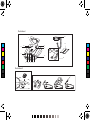
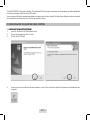
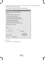
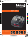
QuintezzDC_cover.pdf 21/04/2010 14:41:23 User’s manual C M Y CM MY CY CMY K GB NL F E D I ADDENDUM MANUAL PAGE GB-GB-4, 6, 11 4.2 SETTING MENU The options ‘Ka’ and ‘KaN (Ka Narrow)’ are replaced by the following options: ‘Ka1’, ‘Ka2’, ‘Ka3’. 4.2.4 RADAR BAND Ka1, Ka2, Ka3 This option allows you to switch off the Radar Band ‘Ka1’, ‘Ka2’ and/or ‘Ka3’. Ka1 (upto 34.3), Ka2 (from 34.3 to 35.1 Ghz), Ka3 (from 35.1 to 35.7 Ghz). 6.2 RADAR FREQUENCIES Ka1: 34.0, 34.3 Ghz Ka 2: 34.3, 34.36, 34.7, 35.1 Ghz Ka 3: 35.5 Ghz ADDENDUM HANDLEIDING PAGINA NL-20, 22, 27 4.2 SETTING MENU De opties ‘Ka’ en ‘KaN (Ka Narrow)’ werden vervangen door volgende opties: ‘Ka1’, ‘Ka2’, ‘Ka3’. 4.2.4 Ka1, Ka2, Ka3 Deze optie laat u toe de Radar Band ‘Ka1’, ‘Ka2’ en/of ‘Ka3’ uit te schakelen. Ka1 (tot 34.3), Ka2 (van 34.3 tot 35.1 Ghz), Ka3 (van 35.1 tot 35.7 Ghz). 6.2 RADARFREQUENTIES Ka1: 34.0, 34.3 Ghz Ka 2: 34.3, 34.36, 34.7, 35.1 Ghz Ka 3: 35.5 Ghz ADDENDUM MODE D’EMPLOI PAGE FR-36, 38 4.2 MENU RÉGLAGES Les options ‘Ka’ and ‘KaN (Ka Narrow)’ ont été remplaçées par les options suivantes: ‘Ka1’, ‘Ka2’, ‘Ka3’. 4.2.4 BANDE RADARKa1, Ka2, Ka3 Cette option vous permet de désactiver la bande radar ‘Ka1’, ‘Ka2’ et/ou ‘Ka3’. Ka1 (jusqu’à 34.3), Ka2 (de 34.3 jusqu’à 35.1 Ghz), Ka3 (de 35.1 jusqu’à 35.7 Ghz). 6.2 Fréquence radar Ka1: 34.0, 34.3 Ghz Ka 2: 34.3, 34.36, 34.7, 35.1 Ghz Ka 3: 35.5 Ghz ADDENDUM MANUAL DE INSTRUCCIONES PAGINA E-52, 54, 59 4.2 MENÚ DE AJUSTE Las opciones ‘Ka’ y ‘kaN (Ka Estrecho)’ son reemplazadas por las siguientes opciones: ‘Ka1’, ‘Ka2’, ‘Ka3’. 4.2.4 BANDE DE RADAR Ka1, Ka2, Ka3 Esta opción le permite apagar la Banda de Radar ‘Ka1’, ‘Ka2’ y/o ‘Ka3’. Ka1 (hasta 34.49), Ka2 (de 34.3 a 35.1 Ghz), Ka3 (de 35.1 a 35.7 Ghz). 6.2 FRECUENCIAS DEL RADAR Y DEL LÁSER Ka1: 34.0, 34.3 Ghz Ka 2: 34.3, 34.36, 34.7, 35.1 Ghz Ka 3: 35.5 Ghz ADDENDUM BENUTZERHANDBUCH SEITE D-68, 70, 75 4.2 EINSTELLUNG MENU Die Optionen ‘Ka’ und ‘KaN (Ka Narrow)’ werden durch die Folgende Optionen ersezt: ‘Ka1’, ‘Ka2’, ‘Ka3’. 4.2.4 RADAR BAND Ka1, Ka2, Ka3 Diese Option ermöglicht das Ausschalten des Radar-Bandes ‘Ka1’, ‘Ka2’ und/oder ‘Ka3’. Ka1 (bis 34.3), Ka2 (von 34.3 bis 35.1 Ghz), Ka3 (von 35.1 bis 35.7 Ghz). 6.2 RADAR FREQUENZEN Ka1: 34.0, 34.3 Ghz Ka 2: 34.3, 34.36, 34.7, 35.1 Ghz Ka 3: 35.5 Ghz ADDENDUM MANUALE DELL’UTENTE PAGINA I-84, 86, 91 4.2 MENU IMPOSTAZIONI Le opzioni “Ka” e “KaN” (Ka Narrow ) sono sostituite dalle seguenti opzioni: “Ka1”, Ka2”, “Ka3”. 4.2.4 BANDA RADAR: Ka1, Ka2, Ka3 Questa opzione permette la disattivazione delle Bande Radar “Ka1”, Ka2” e/o “Ka3”. Ka1 (fino a 34.3 GHz), Ka2 (da 34.3 a 35.1 GHz), Ka3 (da 35.1 a 35.7 GHz). 6.2 FREQUENZE RADAR Ka1: 34.0, 34.3 Ghz Ka 2: 34.3, 34.36, 34.7, 35.1 Ghz Ka 3: 35.5 Ghz Illustration I 15 11 C 13 12 16 10 9 M Y 8 6 CM MY CY CMY K 7 Illustration II 1 2 3 4 5 14 TABLE OF CONTENTS INTRODUCTION ..........................................................................................................................................................................1 DESCRIPTION OF THE DRIVE CONTROL ........................................................................................................................................1 INSTALLATION IN THE CAR ..........................................................................................................................................................2 OPERATION OF THE DRIVE CONTROL IN THE CAR .......................................................................................................................3 SETTINGS OF THE DRIVE CONTROL .............................................................................................................................................4 ALERT SCREENS OF THE DRIVE CONTROL ....................................................................................................................................9 DEFAULT SETTINGS ...................................................................................................................................................................10 SPEED TRAPS ............................................................................................................................................................................10 PC OPERATING FOR THE QUINTEZZ DRIVE CONTROL .................................................................................................................12 MAINTENANCE, DIRECTIVES AND TIPS ......................................................................................................................................15 GUARANTEE .............................................................................................................................................................................15 INTRODUCTION Congratulations! You are now the proud owner of one of the world’s most advanced GPS products. The Quintezz Drive Control is delivered as a GPS Locator for speed checks. It is possible to upgrade the device to a combined GPS Locator / Radar Detector / Laser Detector. The possession and use of a Radar / Laser Detector is forbidden in some countries. Please check if radar detection or laser detection is allowed in your country. The DRIVE CONTROL does not give you the right to exceed the speed limits. Always make sure you drive carefully! DESCRIPTION OF THE DRIVE CONTROL 1.1 GENERAL The DRIVE CONTROL is a device that gives you information about your trip and warns you for unsafe situations. QUINTEZZ supplies a database for several countries with information about speed camera’s and/or dangerous locations. In addition you can save your own locations. A warning will be given at a distance of 600 meters of every location. For the information that is supplied by QUINTEZZ, you have some additional functions. The speed warning is depending from your speed and direction of driving. This means that you won’t get a warning if the camera is at the other side of the road. This also means that you will get a small warning in case of correct speed, but a big warning in case of speeding. Besides this function, your QUINTEZZ DRIVE CONTROL shows you: Compass, an indication of your real speed, your battery voltage, the date and the time -GB-1- 1.2 MEANING OF EACH PART IN THE BOX See illustration I 1. Setting button: To enter the menu options and activate the download mode 2. Save button: i. Allows the user to manually add new locations where from now on warnings will be given in driving mode. ii. Allows the user to manually delete locations. iii. The user’s preference for each option can be set in setting mode. 3. Volume – button: To decrease the volume. 4. Volume + button: To increase the volume. 5. Red button: i. To de-activate the Radar / Laser Detector once you access countries where the Radar / Laser Detector is not allowed: press this button briefly (not longer than 2 sec.!). If you press this button too long, the device will set to ‘illumination’ mode and the Radar / Laser Detector will NOT be switched off. ii. To dim the display (long pressing, until you see ILLU: xxx). 6. PC – USB Port: For downloading data from your computer 7. Display 8. Speaker 9.Laser Detector lens – rear 10. Laser Detector lens – front 11.Radar Detector lens 12. DC 12V: Power port for cigarette plug 13.Lock switch for windshield bracket 14. Windshield bracket 15. Power cord 16. Velcro Manual CD with PC software INSTALLATION IN THE CAR 2.1 DRIVE CONTROL The QUINTEZZ DRIVE CONTROL is especially designed for use in the car. GPS signals are received through the built-in GPS antenna. The following are some guidelines for mounting the detector : • The unit may be positioned within 25° of horizontal without significantly degrading performance. • The information display of the DRIVE CONTROL has to be clearly visible to the driver. • Do not mount directly behind windshield wipers. -GB-2- • • Mount the unit so that the control panel is plainly visible for the driver. Do not leave it in direct sunlight for long periods of time. 2.2 MOUNTING TYPES See Illustration II We have provided 2 types of mounting methods. 2.2.1 DASHBOARD MOUNTING The hook and loop fastener Velcro tape provided, may be used to mount your detector on a flat dashboard. The dashboard must be clean and dry for the fastener to adhere properly. • Remove backing from the “LOOP (fuzzy)” piece and press firmly to the bottom of your unit. • Clean dashboard with common rubbing alcohol to remove dirt and grease. • Peel the backing from the hook side and press the unit into the desired position on the dashboard. 2.2.2 WINDSHIELD MOUNTING • Insert the supplied suction cups and cushion into each slot and windshield bracket. • Slide the windshield bracket into the groove of the detector. • Use the Lock switch (LOCK) to lock the windshield bracket. • Locate the bracket on a clean windshield and press firmly on each suction cup. 2.3 POWER SUPPLY The DRIVE CONTROL is designed to be connected to the normal electrical circuit (12 Volts) of the car, which has a negative earthing. See the manual of your car, if you are not sure about the polarity. After installation, the power cable is to be plugged into the ‘POWER Port’. Remove the cigarette lighter and insert the cigarette plug into this contact accordingly. OPERATION OF THE DRIVE CONTROL IN THE CAR 3.1 AUTOMATIC TEST After being switched on, the DRIVE CONTROL will perform an automatic self test. If you hear the audio text ‘FASTEN YOUR SEAT BELT, BE CAREFUL’, the test has been properly performed and the display will show: > > 3.2 LOOKING FOR SATELLITES Once the automatic test has been performed, the DRIVE CONTROL will try to contact the GPS satellites. The display will show ‘SRCH’ (Search). -GB-3- If the Radar / Laser Detector is installed, it will start working immediately. The GPS alarm will only be working after the connection to the satellites is established. ATTENTION: The first time the DRIVE CONTROL is switched ON, it can take about 15 minutes to catch the satellites. Obstacles in the direct environment and the moving of the car can extend the duration of the first connection to the satellites. The DRIVE CONTROL will stay connected with 4 to 12 satellites. If the connection is shortly cut (for example when passing through flyunders and tunnels) the display will go to connection mode, showing 3.3 DRIVING MODE The DRIVE CONTROL is the perfect solution to prevent you from speeding a few kilometers by accident. When the connection with the satellites is OK, you will see the following display, showing the time. When the car is moving, the real speed and heading is shown. SETTINGS OF THE DRIVE CONTROL 4.1 VOLUME SETTING You can set the volume by the VOL – or VOL + key. 4.2 SETTING MENU The menu button is located at the top of the DRIVE CONTROL and indicated with “SETTING”. By pressing this button, you will access the setting menu that contains the following choices: 1. Rlogic: 0 / 1 / 2 / 3 / 4 / CITY (visible when radar is on) 2. X/Ku: ON/OFF 3. K: ON/OFF 4. Ka: ON/OFF 5. Ka N: ON/OFF 6. MAX: Maximum speed for overspeed warning 7. Default / Details / Comfort: The screen information mode 8. Bell: ON / OFF 9. Lang: SP / FR / GB / D / I -GB-4- 10. 11. 12. 13. 14. 15. 16. 17. SN 0 (visible when radar is off) ODO 0.0 AVG: 0 U: Kilo / Mile GMT: 0 U1 …….Lat ……….Lon Ver 03.1 DB: e.g. 9/11 Each submenu will be described in the following chapters. - To scroll through the menu, press the SETTING button. - To enter a selected menu, press the SETTING button. - To save a selection, press the SAVE button. If no button is pressed within 3 seconds, the unit exits the menu. 4.2.1 RLOGIC: 0 / 1 / 2 / 3 / 4 / CITY This function will only be visible whenever the Radar Detector function is enabled. The Radar Logic setting determines at which speed the Radar Detector starts working. - - - - - - Logic0: The Radar Detector works always, so starting from 0 km/h. Logic1: The Radar Detector starts working when the driving speed exceeds 20 km/h. Logic2: The Radar Detector starts working when the driving speed exceeds 40 km/h. Logic3: The Radar Detector starts working when the driving speed exceeds 60 km/h. Logic4: The Radar Detector starts working when the driving speed exceeds the maximum speed chosen manually by you in the menu. (see chapter 4.2.5 ‘MAXIMUM SPEED’) CITY: The Radar Detector works always, but the sensitivity is reduced to eliminate most false sources so that the unit will not alarm for weak signals. There are many sources of false alarm signals near cities. There are for instance several types of automatic doors that use the same signal as a radar. As soon as you have activated this CITY mode and you have set the display information mode (see chapter 4.2.6 ‘DEFAULT /COMFORT /DETAILS…’) to ‘Comfort’, the ‘C’ of CITY is shown together with the heading of the compass: E.g. Logic 2: Whenever de Radar Detector function is activated and you are driving 30 km/h, the Radar Detector is activated but will not give you a warning as soon as it detects radar signals. As soon as your driving speed exceeds 40 km/h you will start receiving all warnings. This function enables you to determine when the Radar Detector starts working in order to avoid false alarm signals. If there is no connection between the GPS and the satellites, the Radar Detector will still work in RLogic0 setting, as long as it has been enabled. -GB-5- 4.2.2 RADAR BAND: X/Ku This option allows you to switch off the Radar Band ‘X/Ku’. - Press the VOL + or VOL – button to switch this Radar Band ON or OFF. - To confirm this setting, press SAVE. 4.2.3 RADAR BAND: K This option allows you to switch off the Radar Band ‘K’. - Press the VOL + or VOL – button to switch this Radar Band ON or OFF. - To confirm this setting, press SAVE. 4.2.4.1 RADAR BAND: Ka / 4.2.4.2 RADAR BAND: Ka Narrow (Ka N) This option allows you to switch off the Radar Band ‘Ka’ / ‘Ka N’. - Press the VOL + or VOL – button to switch this Radar Band ON or OFF. - To confirm this setting, press SAVE. 4.2.5 MAXIMUM SPEED FOR OVERSPEED WARNING The following display appears once the warning limit menu is accessed: The maximum speed can be set by the user in this mode. - Press the VOL + or VOL – button to set a maximum speed. - If the user exceeds a maximum speed, a speed alert is displayed followed by a warning sound. - To confirm the set warning limit, press SAVE. 4.2.6 DEFAULT / COMFORT / DETAILS: THE DISPLAY INFORMATION MODE The DRIVE CONTROL has a display. The information on the display depends on whether you are driving or not. This information can be selected: Details display setting: During driving the speed of the car and the heading are shown. During non-moving the date, the trip time and the battery voltage are shown. Default display setting: During non-moving, the time is shown. -GB-6- During moving, the speed of the car and the heading are shown. Comfort display setting: During moving and non-moving, the heading of the compass is shown in degrees. If you have set the RLogic function to ‘CITY’ (see chapter 4.2.1 ‘RLOGIC…’), the ‘C’ of City is also shown on the display. 4.2.7 BELL / EXTRA SOUND The following display appears once the bell / extra sound menu is accessed: This option allows you to partially switch off the sound. - Press the VOL + or VOL – button to switch the sound ON or OFF. - To confirm this setting, press SAVE. If you have selected OFF, the following sounds will not be audible: - Start-up message: Fasten your seat belt, be careful. - Warnings for cameras, in case you are NOT speeding. 4.2.8 LANGUAGE The following display appears once the language menu is accessed: - - Press the VOL + or VOL – button to select the preferred language. To confirm this setting, press SAVE. 4.2.9 SN 0 DISPLAY This is only shown whenever the Radar Detector function is de-activated. To activate the Radar Detector, it needs to have the software enabled. To enable this software, you need to enter a secret code. The secret code consists of the last 4 digits of the serial number. -GB-7- First, you need to enter the first digit. You can set the digit with the VOL + and VOL – key. To confirm the digit, you need to press the red button. Once all 4 digits are confirmed, the Radar Detector will be switched on, or you will receive a message ‘SN Fail’. To make sure your secret code remains secret, we suggest that you remove the last 4 digits from the serial number label, and store the information in a safe place. 4.2.10 0.0 INDICATION When the product is not used, the display shows 0.0. This is the ODO meter. It shows the total traveled distance. To reset the Odometer to 0.0, press the red button. 4.2.11 AVG INDICATION This display indicates the average speed of your trip after switching on the unit. When you switch off the unit, your average speed will automatically be reset. 4.2.12 U: KILO / MILE The following display appears once the speed indication menu is accessed: With this indication you can choose whether your speed needs to be indicated in Kilometers/hour or Miles/hour. 4.2.13 GMT SETTING The satellites broadcast the time based on GMT (Greenwich mean time). This time is not changed automatically from summer into winter time. To adjust the time to your region / season, you have to increase or decrease the hours. E.g. to set the unit to Amsterdam / Brussels / Paris summertime, you have to set this to 2. 4.2.14 U1 LON ….. LATT …… You can save your own locations into the DRIVE CONTROL. The DRIVE CONTROL will give a warning once you reach these locations. In this menu, you can see the coordinates of your own stored locations. 4.2.15 SOFTWARE VERSION The following display appears once the software version menu is accessed: This display shows you the current version of the software. 4.2.16 DATE OF DATABASE The following display appears once the date of database menu is accessed: This display shows you the date when the database was last updated (DD/MM). -GB-8- ALERT SCREENS OF THE DRIVE CONTROL The DRIVE CONTROL will show the following screen when you approach a speed camera. The following alert indicates a camera warning at a distance of 450 meter on the current road. While driving, the DRIVE CONTROL will give a warning sound when you approach a camera, a dangerous location, a track control section or a user data location. The sound of this warning depends on what you have set up for the ‘bell / extra sound’. In case this setting has been switched OFF, there will only be a warning whenever the speed limit is exceeded. The maximum speed on the particular location will also be shown on the display. In case this setting is ON, there will be a warning for every camera. The first warning will be given at a distance of 500 meters. The second warning (KEEP SAFETY DRIVING) will be heard at a distance of 300 meters. 5.1 CAMERA & TWO-WAY CAMERA This alert indicates a camera or a two-way camera warning at a distance of 450 meter on the current road. Please check your speed and slow down in case of overspeed. At a distance of 500 meter of the camera you will hear ‘CAMERA’ or ‘TWO WAY CAMERA’ and at a distance of 300 meter the DRIVE CONTROL will say ‘BE CAREFUL’. 5.2 DANGEROUS LOCATION, TRACK CONTROL & TRACK CONTROL END track control dangerous location warning This alert indicates a dangerous location, a track control or a track control end at a distance of 450 meter on the current road. Please check your speed and slow down. At a distance of 500 meter of the location you will hear ‘DANGEROUS LOCATION’, ‘TRACK CONTROL’ or ‘TRACK CONTROL END’ and at a distance of 300 meter the DRIVE CONTROL will say ‘BE CAREFUL’. 5.3 A USER REGISTERED LOCATION You can manually add and delete locations from the memory of the DRIVE CONTROL while driving. These locations are called ‘user data’ and can be exchanged with other people using the DRIVE CONTROL. The memory for user data has a capacity of 800 locations. -GB-9- How to add a location? If you want to add a location manually, press the SAVE button at that location, while you are driving. The DRIVE CONTROL will confirm the saving of this location as indicated in the following display: (in this case the 3rd user location was saved). How to delete a location? If you want to delete a manually added location, press the SAVE button at the respective location. This needs to be done during the visual and audible alarm for this particular location. The location will be deleted and the DRIVE CONTROL will confirm the deleting of this location as indicated in the following display: When you are driving, and when you are at a distance of 500 meter of a user’s location that has been saved in the memory of your DRIVE CONTROL, a warning will be shown and you will hear ‘DING DONG’ and ‘WATCH OUT’. When you are at a distance of 300 meter, the DRIVE CONTROL will repeat ‘DING DONG DING DONG’. The alert shown hereafter indicates a user point warning at a distance of ������������� 450 meter. 5.4 SPEED ALERT There are two kinds of speed alert warnings showing the above display: ‘warning limit speed alert’ and ‘system limit speed alert’. In case of a ‘warning limit speed alert’, you will hear a ‘DING’ tone. In case of a ‘camera limit speed alert’, you will hear ‘TING TING TING’ with a loud, sharp tone. DEFAULT SETTINGS 1. 2. 3. 4. Warning limit: 130 km/h Clockbell: ON Language: English Speed indication: Km/h SPEED TRAPS Police checks can be effected in many different ways. Frequently used speed-trap methods are radar speed cameras, laser guns, mobile radar speed cameras and track controls. -GB-10- 6.1 HOW THE RADAR WORKS The actual process involved in determining a vehicle’s speed is basically a simple one. It involves directing a beam of microwave energy at an approaching target vehicle. A portion of this beam is reflected by the target and is received by the radar unit that originally transmitted the signal. The reflected signal is shifted in frequency by an amount proportional to the speed of the target vehicle. This phenomenon is known as the Doppler effect. The radar unit determines the target vehicle speed from the difference in frequency between the reflected signal and original signal. To activate the Radar Detector, please read chapter 4.2.9 ‘SN 0 Display’. To de-activate the Radar Detector press the red button briefly (not longer than 2 sec.!). If you press this button too long, the device will set to ‘illumination’ mode and the Radar Detector will NOT be switched off. 6.2 RADAR FREQUENCIES The QUINTEZZ DRIVE CONTROL can detect 5 radar bands with 14 different frequencies and includes Instant ON radar and POP radar. X band: 9.41 Ghz, ��������������������������������������� 9.9 Ghz, 10.5 Ghz, 10.525 Ghz, 10.6 Ghz Ku band: 13.450 Ghz, K band: ��������������������������� 24.1 Ghz, 24.125, 24.15 Ghz Ka narrow-band: 34.0 Ghz, 34.3 Ghz, 34.36 Ghz Ka wide-band: 34.7 Ghz, 35.5 Ghz POP detection 6.3 LASER DETECTION Laser detection is another kind of signal that can be detected. Laser Speed Guns use pulses of infrared laser light to measure speed of target by timing each pulses over time as it is reflected back to the gun. 6.4 LASER RANGE The effective range of clocking distance by a laser gun is less than 1 km. The operator of the laser gun is instructed to target on the number plate. So, mount your laser detector as low as possible in the car. The QUINTEZZ DRIVE CONTROL offers the possibility to detect a laser from front as well as from behind. If the Laser Detector is activated by reflection signals from the laser beam to a vehicle in front of you, then you still have time to react on the laser check. If the Laser Detector is activated by a laser beam that is pointed on your car, then your speed is already measured during the laser alarm. 6.5 OTHER SPEED CHECKS There are a couple of other checks that cannot be detected by Radar or Laser Detectors. These checks include digital video recording, loops within the road and optical speed checks. These checks have to be detected by GPS. A Radar Detector is able to detect several of these traps, but not all of them. The new generation of radar speed traps is increasingly difficult to detect by means of a Radar Detector. Furthermore, the Radar Detector is forbidden in many countries. False alarms occur on a regular basis with each and every Radar Detector. -GB-11- The DRIVE CONTROL is the perfect solution. This advanced GPS device signals overspeed, camera locations and offers additionally an electronic compass, trip time and an ODO-meter. You can activate the Radar/Laser detection update in countries where this is allowed. The Radar/Laser Detector can be set to switch off at speeds that are lower than 30 or 50 km/h to avoid false alarms. PC OPERATING FOR THE QUINTEZZ DRIVE CONTROL 7.1. INSTALLING �������������������������������� THE QUINTEZZ SOFTWARE 1.Insert the CD into the CD-ROM network drive. 2. Choose the language and click on ‘Next’. 3. Click on ‘Next’ ‘Install’. 4. As soon as you have installed the Quintezz software, an icon ‘Drive Control Easy Update’ will appear on the desktop of your computer. -GB-12- 7.2. DOWNLOAD DATABSE CAMERA LOCATIONS 1. Click on the icon ‘Drive Control Easy Update’, created during the installation of the Quintezz software (see step 1). 2. Go to www.quintezz.com and choose English as language. 3. Click on ‘Download Center’. 4. Click on ‘Accept’ to accept the Quintezz juridical statement. 5. Select the database of your choice. 6. Click on ‘Download’ to confirm your choice. 7. Save the file ‘DriveControl.mdb’ on your desktop. 8. In a few moments the message ‘Download complete’ will appear on your screen. Click on ‘Close’. 7.3. 1. 2. 3. UPDATE YOUR QUINTEZZ DRIVE CONTROL Close the site www.quintezz.com. First of all, connect the USB cable to your computer. Take your Drive Control and press the button ‘SETTING’. Now keep this button pressed while connecting the Drive Control to the other end of the USB cable. When you have connected the Drive Control correctly, the display will show ‘DOWNLOAD’ and ‘Quintezz is linked’ will be shown on the screen of your computer. If the button ‘SETTING’ was not pressed while connecting the USB cable to the Drive Control, the software will not be able to start downloading the database. In this case you will have to try again, starting from step 3. -GB-13- 4. Click on ‘Database’ and select the file ‘DriveControl.mdb’ that was saved on your desktop. The software will now start downloading the database into your Drive Control. !!! Do not unplug the Drive Control until ‘ALL DONE’ is shown on your screen!!! 5. 6. Click on ‘Exit’. Your Drive Control is now up-to-date and ready to use! -GB-14- MAINTENANCE, DIRECTIVES AND TIPS 8.1 REPLACING THE FUSE There is a fuse in the cigarette plug of the DRIVE CONTROL. To replace the fuse, you need to loosen the screw cap of the cigarette plug. Always make sure you replace the fuse with one of equal value. 8.2 ENVIRONMENT The DRIVE CONTROL is a very advanced GPS-system that is composed with high-quality components. Extreme low and high temperatures, heavy shocks, etc. should be avoided. Do not expose the DRIVE CONTROL to direct sunlight. 8.3 THEFT QUINTEZZ appliances are also attractive to people with not so good intentions. In order to prevent theft, we advise you not to leave your DRIVE CONTROL unattended in your car. GUARANTEE QUINTEZZ is a registered trademark of TE-Group NV. The QUINTEZZ brand stands for superior product quality and outstanding customer service. That is why QUINTEZZ warrants this product against all defects in material and workmanship for a period of two (2) years from the date of original purchase of the product. The conditions of this limited guarantee and the extent of responsibility of QUINTEZZ under this limited guarantee are as follows: • This guarantee is limited to the original purchaser of the product and is not transferable to any subsequent purchaser/ end user. • During the limited guarantee period, the sole responsibility of QUINTEZZ will be limited to repair or replace, at its option, any defective parts of the product if this is needed because of malfunction or failure under normal use and conditions. No charge shall be made to the customer for parts and/or repair labor. • The product must be shipped to an authorized service center in its original and complete packaging, with transportation charges prepaid. QUINTEZZ will not assume responsibility for any losses or damages during transportation. • To obtain repair or replacement within the terms of this guarantee, the customer must provide (a) a proof of purchase (e.g. dated bill of sale); (b) a written specification of the defect(s); (c) a return address and phone number. • This limited guarantee does not cover and is void with respect to the following: (a) Products which have been subjected to improper installation, unauthorized repair, improper maintenance, unauthorized modifications or other acts which are not the fault of QUINTEZZ; (b) Products which have been subjected to misuse, abuse, neglect, improper handling and storage, an accident or physical damage; (c) Products which have been subjected to fire, water, excessive humidity, sand, dirt, extreme changes in temperature or other conditions which are beyond the control of QUINTEZZ; (d) Products which have been used with non-QUINTEZZ approved accessories; (e) Products which have the serial number altered, defaced or removed; (f) Products which have been opened, altered, repaired or modified by any unauthorized service center. -GB-15- • • • Excluded from any guarantee are consumable items which may need replacing due to normal wear and tear, such as batteries, ear cushions, decorative parts and other accessories. This limited guarantee gives you specific legal rights, and you may also have other rights which vary from country to country. Excluded from the guarantee are eg.: problems with your PC or Internet, damage to your car and fines. If there are any problems or uncertainties, you can ask your questions through [email protected]. -GB-16- QuintezzDC_backcover.pdf 21/04/2010 14:40:48 C M Y CM MY CY CMY K Drive Control/05-10/V04 PATENTED - ALL RIGHTS RESERVED