1
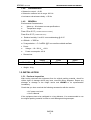
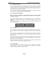
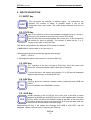
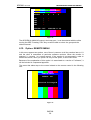
Professional Monitors 9” BM5309A12 (V.3-4)/A13 User Manual BM5309D13 Edition 01 2002 KROMA TELECOM Pol. Ind. Alcobendas - C/ La Granja, 80 28108 Madrid - ESPAÑA Tel. (34-91) 661 45 14 Fax. (34-91) 484 03 49 www.kromatelecom.com KROMA TELECOM PROFESSIONAL MONITORS BM5309 SAFETY INFORMATION WARNING: This product includes critical mechanical and electrical parts which are essential for X-Radiation safety. For continued safety replace critical components indicated in the service schematic only with exact replacement parts given in the parts list of service Manual. Operating high voltage for this product is 16 Kv. At minimum brightness. Refer to service manual for measurement procedures and proper service adjustments. WARNING: Electric shock or fire hazard can be caused if critical components are replaced by non conform components. Refer to parts list of service manual. CAUTION: High vacuum tube is dangerous to handle refer replacement to qualified personnel. Replace with a tue of the same type for continued safety BM5309 1 KROMA TELECOM PROFESSIONAL MONITORS BM5309 1. INTRODUCTION 1.1. APLICATIONS The KROMA BM5309 monitors have been designed to use in Broadcast studios for signal evaluation requiring accurate picture reproduction. Also it can be used in postproduction.. They incorporate microprocessor based control in all its operations, providing automatic color set-up, thus eliminating the operator´s subjetive factor. 1.1.1. FEATURES BM5309A12 9" Basic Video version: CCVS (PAL/NTSC). Three composite video inputs, one of them is configurable as external sync. Options: BM5009X01 This module consist of 2 Digital video inputs in passive loop-through, according to (ITU-R BT601) 10 Bits and analog components (RGB/YPrPb). BM5009X02 This module consist of 2 Digital video inputs in passive loop-through, according to (ITU-R BT601) 10 Bits and analog components (RGB/YPrPb). This SDI module allows the user to extract the embedded audio and then output it in Analog or AES EBU Digital form. BM5309A13 9" It can be configured with the following options: BM5309X01 This module consist of 2 Digital video inputs in passive loop-through, according to (ITU-R BT601)10 Bits BM5309X02 This module consist of 2 Digital video inputs in passive loop-through, according to (ITU-R BT601) 10 Bits. This SDI module allows the user to extract the embedded audio and then output it in Analog or AES EBU Digital form. BM5309X03 This module consist of 1 PAL,NTSC,SECAM video input and 2 Digital video inputs in passive loop-through, according to (ITU-R BT601) 10 Bits BM5309X04 It is the more complete version (module), it has all the options previously mentioned. BM5309 0 KROMA TELECOM PROFESSIONAL MONITORS BM5309 1.1.2. PICTURE TUBE High resolution, in line guns an shadow mask tube, with 0.28 dot pitch and P22 phosphor. 1.1.3. COLOUR STABILITY Beam current feedback, which allows to correct colour temperature drift caused by CRT variation and environmenttal conditions. 1.1.4. FLEXIBILITY Modular configuration. It is provided with an analog and digital bus, allowing the exchange of signals between the options installed, making it a system of open architecture for future options. 1.1.5. AUTO SETUP SYSTEM By use of the KROMA set AK5400X50, composed by a DG5400 test signal generator and an optical probe model SR5400.The generator is able to provide up to 34 patterns designed for monitors alignment. With this combination, automatic grey scale adjustment can by carried out. This set also allows transfering automatically the parameter setting of this setup to other monitors. 1.1.6. REMOTE CONTROL The RS-485 bus included in the BM5309 KROMA monitors. Is able to control up to 128 monitors. These can be in group controlled, individually controlled or all of them can be controlled at the same time by remote control RK5000. 1.1.7. MENU This help the operation, displaying the operating parameters .and the commands to access at several functions. The adjustment operations to be done by the specialized personnel are protected by numerical password. 1.1.8. NORMAL SIZE, UNDERSCAN AND 16:9 The BM5309 range provides facilities for normal picture size or underscan (95% reduced size) and aspect ratio 4:3 and 16:9 selectable from the front panel by SIZE key. 1.1.9. MEMORIES The monitor has 5 available memories • All memories accessible via password (only for data store) • Four memories for general use. • One memorie for the system or factory BM5309 1 KROMA TELECOM PROFESSIONAL MONITORS BM5309 1.2. TECHNICAL SPECIFICATIONS 1.2.1. SCAN & SYNC Systems 625/50/2:1 Horizontal frequency 15.625 Hz 525/60/2:1 Horizontal frequency 15734 Hz Horizontal oscillator lock-in range: ± 750 Hz Horizontal sync. constant time: Fast: 0.5 mS Slow: 2.5 mS 1.2.2. PICTURE DISPLAY Aspect ratio: 4:3 and 16:9 - Linearity error: ≤ 4 % of picture height Errors: - Geometry error: ≤ 1 % ídem. - Convergene error: TUBE 9” ZONE 1 0.4 mm REST 0.5 mm ZONE 1 IS WITHIN A CIRCLE CENTRED ON THE SCREEN WHOSE DIAMETER IS EQUAL TO PICTURE HEIGHT. 1.2.3. CTR • 9” HR 0.28 dot pitch Phosphor: P22 • Resolutión : > 450 TV línes a centre • Colour temperature: 6500º K ± 200º K (IN ALL MEMORIES) • Black level: Set to 0.5 Nit (10 % APL WINDOW SIGNAL) • White level: Set to 90 Nit (100% APL WINDOW SIGNAL) • Beam current limiting: 180 Nit (FLAT FIELD SIGNAL) 1.3. BM5309A12 MODEL 1.3.1. DECODER PAL / NTSC PERFORMANCE • Inputs A, B and C ♦ Level : 1 Vpp +3/-6 dB ♦ Impedance : 75 Ω ± 1% or loop-through (selectable) ♦ Return losses: 35 dB @ 5 Mhz. ♦ Isolation between A, B and C inputs: > 60 dB @ 10 Mhz. ♦ Mismatch between A and B inputs: < 1% and < 1º @ 4.43 Mhz • External sync input ♦ Level : 4 VPP +6 dB / -28 dB ♦ Impedance : 75 Ω ± 1% or loop-through (selectable) ♦ Return losses: > 35 dB @ 5 Mhz BM5309 2 KROMA TELECOM • PROFESSIONAL MONITORS BM5309 Auxiliary signal (Front panel) 1 ♦ Format : CCVS similar to A and B ♦ Impedance : 75 Ω ± 1% ♦ Return losses: > 25 dB @ 5 Mhz. 1.3.2. LUMINANCE • Frequency response: Without notch filter: 100 Khz - 6 Mhz ± 1 dB Notch filter suppresion < - 30 dB @ 4.43 Mhz • K factor (APERTURE 0 dB) WITHOUT FILTER WITH FILTER Kpb < 0.5 % < 1% K2T < 0.3 % < 1.2% • Non linearity: < 1% • Noise: (100 Khz - 5 Mhz) < 60 dB 1.3.3. CHROMINANCE • Saturation control: ± 6 dB • Subcarrier oscillator lock.in range: 300 Hz • Luminance-crominance delay : < 50 nS 1.4. BM5309A13 MODEL 1.4.1. SDI FEATURES Compatible with signal source according to norm ITU-R BT.601 and BT.656 SMPTE/EBU of 270 Mbits per second. 1 ♦ Demultiplexed of components and synchyronization according to Rec.601 and Rec.656 of CCIR. ♦ S1 and S2 video inputs in loop-through. Impedance 75Ω ♦ Return losses: > 21 dB @ 270 Mhz. or loop-through (selectable) ♦ Frequency response: ♦ Tilt (V): ♦ K factor: ♦ Non lineality: < 1% 0 – 5,5 Mhz. < 0.5 dB < 0,5 % Kp < 0,3 % Kpb < 0,2 % During the auto set-up it control the channels R G B in parallel. BM5309 3 KROMA TELECOM ♦ PROFESSIONAL MONITORS BM5309 Missmatch between components: Gain: Delay: ♦ < 0.1% < 3 ns Analog audio levels: (Only in BM5309X02 and BM5309X04) 4Vpp @ 0dBFs Nota: The audio outputs are not designed to work with 4 or 8 Ohm loads, it must be connected to inputs with loads >1K Ohm. 1.4.2. DECODER PAL / NTSC / SECAM PERFORMANCE ♦ Input A ♦ Level : 1 Vpp +3/-6 dB ♦ Impedance : 75 Ω ± 1% or loop-through (selectable) ♦ Return losses: 35 dB @ 5 Mhz. ♦ Isolation between A, B and C inputs: > 60 dB @ 10 Mhz. ♦ Mismatch between A and B: < 1% and < 1º @ 4.43 Mhz ♦ External sync input ♦ Level : 0.3 VPP (Black burst) +6 dB / -28 dB ♦ Impedance : 75 Ω ± 1% or loop-through (selectable) ♦ Return losses: > 35 dB @ 5 Mhz ♦ Auxiliary Input (Front panel)2 ♦ Format : CCVS similar to A and B ♦ Impedance : 75 Ω ± 1% ♦ Return losses: > 25 dB @ 5 Mhz 1.4.3. ♦ LUMINANCE Filter: By “Comb filter” adaptive PAL/NTSC of three lines. ♦ Frequency response: 100 Khz – 5.5 Mhz ± 1 dB ♦ K factor: Kpb < 2% K2T < 3.5% ♦ Differential Gain: 2º ♦ Differential Phase: 2% 2 During the auto set-up it control the chanel R G B in parallel. BM5309 4 KROMA TELECOM 1.4.4. PROFESSIONAL MONITORS BM5309 CHROMINANCE • Saturacion control: ± 6 dB • Subcarrier oscillator lock in range: 300 Hz • Luminance-chrominance delay: < 50 Ns 1.4.5. GENERAL Enviromental Characteristics: ♦ Warm-up : 20 minutes to meet specifications. ♦ Temperature range: From 15 to 40 ºC (TO MEET SPECIFICATIONS) From 0 to 45 ºC (OPERATING ONLY) ♦ Relative humidity: 0 to 90 % non considensing @ 40 ºC ♦ Altitude : ≤ 3000 m. ♦ X-ray emision: < 0.1 mR/Hr @ 5 cm monitor outside surface. • Power ♦ Voltage : 110 / 220 VAC ± 20% ♦ Power consumption: 45 W • Dimensions: Model 9” Height 218 mm. (5 UR.) Width 222 mm. Depth 420 mm. • Weight : 8 Kg. 1.5. INSTALLATION 1.5.1. Previous Inspection After having removed the equipment from its original packing material, check for visible signs of damage which may have occurred during shipment. Report any shortage or damage to the freight carrier and KROMA or its representative inmediately. Check that you have received the following accessories with the monitor: • AC power cord, and • User´s Manual. If the equipment has to be reshipped to a long distance, it is recommended to use the original packing material in order to avoid damages during transport. BM5309 5 KROMA TELECOM PROFESSIONAL MONITORS BM5309 1.5.2. Safety Information For electric shock protection, it is necessary to connect the chassis to a protective ground; to this purpose, the earth ground terminal of the plug is directly connected to the metal part of the monitor (green-yellow wire). Insert the power plug in a mating outlet with an earth ground contact. Due to the presence of high voltages inside the equipment, the same can only be open, adjusted or repaired by QUALIFIED PERSONNEL. 1.5.3. Connection to the Main Before connecting the monitor to the mains, check that the mains voltage corresponds to that indicated in the voltage selector located in the rear panel, next to the mains connector. If the mains voltage presetting is not the appropriate, carry out the change by removing the fuseholder and turning it until the desired value is shown in the window. Fuses should be changed in accordance with the mains voltage presetting used, as per the following table: POWER 220 V 110 V FUSE 2.5 A Slow 3.15 A Slow 1.5.4. Location Due to the CRT´s sensitivity to magnetic fields, avoid installing the monitor near this type of disturbance sources such as: Loudspeakers, electric motors, transformers, etc. The monitor has a dagaussing device incorporated which operates automatically when the equipment is switched on. It can also be activated manually from the front panel controls. If the monitor is changed of location, some colour impurities may occur due to the variation of the earth magnetic field. This problem disappears by activating the degaussing circuit with the DEG key. During the time this operation last, avoid placing near the monitor items which have magnetic information such as: tapes, cassettes, cards, etc. 1.5.5. Tally Lamp This lamp, located on the monitor´s front panel, can be activated with voltages within the range + 24V and + 48 V, or by closing of the contacts 2 and 3 of the connector located in rear panel. (SEE FIGURE). BM5309 6 KROMA TELECOM PROFESSIONAL MONITORS BM5309 1.5.6. Ground Terminals There are two ground terminals: protective ground and electrical earth or ground from the power supply. They are normally connected by means of a metal jumper, but they can be isolated one another by eliminating said jumper, in case it is necessary to avoid hum pickups due to the installation. 1.5.7. Remote Control Connectors (RS-485 Interface) They are located at the rear of the video unit. The connectors, in loop through configuration, are prepared for connection of the KROMA RK-5400 remote control.This connector, are also useful for to update the futures software versions Configuration Terminal “ “ “ “ “ “ “ 2 3 4 5 6 7 8 1 - - S/C DATA + (RS485) RX (RS232) GND S/C TX (RS 232) DATA - (RS 485) GND Figure 1 BM5309 7 REM KROMA TELECOM PROFESSIONAL MONITORS BM5309 2. INPUTS SELECTION 2.1. INPUT key INPUT This key allows the selection of diferent inputs , by consecutive key presses. The number of states, or possible inputs, it rely on the assignment that it has made. This could change between one and six inputs. 2.2. CCVS Key CCVS Key for the selection of one of the available composite inputs A , B and C. (C input is only possible if the SYNC key is in the OFF mode). The first time that is pressed appears the current and in the second time will switch the input at following. The number of states will be 1 or 2, relying on the state of the SYNC key. This will be only possible if the Decoder CCVS option is installed. In BM5309A13 monitor there is only one input A. When this key has been pressed will appear the message: INPUT: CCVS X it will disappear lapsed a few seconds, or pressing ESC key. 2.3. CDV key CDV The operation of this key is similar to CCVS key, but in this case it will allows the selecction between digital video input S1 and S2. To press this key it will appear the message: S1 or S2 that will disappear lapsed a few seconds, or pressing ESC key. 2.4. CAV Key This key allows the selection between analog component input RGB and YPrPb YPrPb YPrPb. CAV It is not available in the BM5309A13 model. 2.5. AUX Key AUX Similar operation to the CCVS key, but in this case it will allow to select between AUX RGB and AUX DEC video (only with installed option Decoder CCVS). When we select AUX RGB the signal to the BNC in the front panel of monitor drives the signal to the three guns (R G B) at the same time and therefore we will see a black and white image. Afterpressing this key, it will appear the message AUX RGB or AUX DEC, that will disappear lapsed a few seconds, or pressing the ESC key. BM5309 8 KROMA TELECOM PROFESSIONAL MONITORS BM5309 3. AUXILIARY FUNCTIONS 3.1. SYNC Key SYNC Key for the selection of internal or external sync. However this function can be enabled by programming of the this option in sub-menu, in this case the input CCVS C in BM5309A12. After pressing this key, will appear the following messages: SYNC: INT or SYNC: EXT Or: SYNC-KEY OFF The messages disappear lapsed 4 seconds or pressing ESC key. 3.2. SIZE Key SIZE Key to select between overscan,normal size and underscan reduced size at 95%: This selection is possible, as much being programed the monitor with an aspect ratio 4:3 or 16:9 (See menu options). After to press this key, will appear the following messages: SIZE: NORM 4:3 or SIZE: U/S 4:3 Or: SIZE: NORM 16:9 or SIZE: U/S 16:9 The message disappears lapsed 4 seconds, or pressing ESC key. 3.3. DEG Key Key to manually degauss the monitor CTR. DEG Indirect action by means of relay microprocessor controlled. - Time of activation: 4 seg. - Minimal time for the next activation after the degaussing > 5 min. After to press this key, will appear the following message: DEGAUSSING 3.4. STS (STATUS) Key This key allows the programming of the internal parameters of the monitor through menus. In the Status menu, this key operates in recurrent mode. When pressed, are displayed the configuration parameters or return to the main menu (STS). BM5309 9 KROMA TELECOM PROFESSIONAL MONITORS BM5309 3.5. ESC Key This key will allow us to return to previous menu and interrupt procedures. When you return from the previous menu or shown some of the controls (BLK, CNT,...), if any parameter has been modified,it will save in static mode in the working memory. ESC 3.6. 16:9 Key This key allows to select the aspect ratio 4:3 and panoramic format 16:9 16:9 When this key has been pressed, will appear the message: SIZE: 16:9 SIZE: 4:3 3.7. MONO Key MONO This key has 2 differents states, that could switch in cyclic mode: MONO : AUTO In this case, the monitor present color images, if the signal has “BURST” MONO : FILTERED The monitor will present an image in black and white, but with the luminance filter activated. 3.8. AFC Key AFC This key allow switches in cyclic mode between fast or slow time constant in the capture H sync. When this key has been prassed, will appear the message: AFC : FAST AFC : SLOW 3.9. DEL Key DEL key for selection of the horizontal delay as vertical delay (“PULSE CROSS”) It allows to control the presentation of sync pulses switching between: NORMAL → H DEL → V DEL → H + V DEL NORMAL → H+V DEL In model A13 BM5309 10 in the screen, In model A12 KROMA TELECOM PROFESSIONAL MONITORS BM5309 4. COMMAND KEYS FUNCTION 4.1. BLK KEY (BLACK LEVEL/BRIGHT) BL K By pressing of this key from the normal mode, a message appears in the screen, indicating the current value of the black level, (Brightness) and if the value has been calibrated or not. BLACK LEVEL 00 CAL or BLACK LEVEL +10 UNCAL Starting from this instant are entered in the modification mode of this value by means of 3 the ORE , increasing in the clockwise and decrease in counterclockwise. The maximum BLK valor is +20 and the minimum is -20. If being in this mode of work, the CAL key is pressed , the value of the black level is updated regarding the calibration value (see Appendix A), also is possible to reach the calibration value by means of the ORE(3). The exit from this mode of control of Level of Black (Brightness), to normal mode (without messages in screen) it is performed: automatically, after 4 seconds without pressing any key or manually by pressing ESC key. 4.2. CNT (CONTRAST) CNT Similar behavior to the described above, for BLCK but concerning to the gain of the final video amplifier (Contrast). The messages that could appear are: CONTRAST 00 CAL or CONTRAST -12 UNCAL 4.3. SATURATION/COLOUR SAT Similar behavior to the described above, for CNT but concerning to the gain of the decoder´s chrominance amplifier. This key acts on two parameters. If the active input signal is NTSC, the system internally will select the saturation of NTSC, modifiying this value. For any other system will adjust the same parameter automatically, the system of the active signal is detected and adjusts the control of saturation. The messages that could appear are: SATURATION 00 CAL or SATURATION +8 UNCAL 3 ORE: Optical Rotary Encoder BM5309 11 KROMA TELECOM PROFESSIONAL MONITORS BM5309 4.4. HUE/TINT (NTSC only) HUE Similar behavior to the described for BLCK concerning to the chrominance phase regarding to the burst in the decoder. Because is a parameter of the NTSC system will only be permitted their modification when the active signal corresponds to this system. The messages that could appear are: HUE 00 CAL or HUE -3 UNCAL Or: NO AVAILABLE If the conecting signal is not NTSC 4.5. APT/VOL (APT/VOLUME) APT VOL This key is programmable in BM5309A13 model with the function "PROG. FUNCTION". See menu STS, when is selected S1, S2 digital input. If this key in a monitor not equipped with this option is pulsed will appear the message: NO AVAILABLE. When a CCVS video input is selected in BM5309A12 model, this key allows to control the signal aperture. 4.6. CAL Key Two operating modes: CAL 1. When CAL is pressed, being in one of the modes: BLCK, CNTR, APT, HUE or SAT,the behavior is the described already. 2. The monitor utilizes different menus on those that there is diverse active options. With the ORE select the option and with the CAL key executes the selected option. 3. In Calibration of values in SETUP MANUAL. BM5309 12 KROMA TELECOM PROFESSIONAL MONITORS BM5309 5. INDICATORS 5.1. UNCAL LED This LED is kept activated (Red LED lit) if any of the variables:BLK, CNTR, APT, HUE or SAT, has a different value of the calibration. In order to proceed to the calibration of this variable, see previous paragraph, and the behavior of the CAL key with the modes BLCK , CNTR, APT, HUE or SAT. 6. MENUS OPERATION The STS key shows the STATUS menu through the which gives up pass to all the submenus, which they allow to configure all the parameters and functions from the monitor. 6.1. STATUS MENU When the STS key is pressed from the normal operation mode, the following menu will appear: STATUS MENU MEM RECALL SET UP PASSWORD TECH. MENU SAFE AREA MEM STORE CONFIG INPUT KEY PROG FUNCTION REMOTE EMBEDDED AUDIO Use Wheel and CAL Figure 2 The different options selection is carried out by means of the O.R.E. (Optical Rotary Encoder), and in order to activate the function we will press CAL key. BM5309 13 KROMA TELECOM PROFESSIONAL MONITORS BM5309 6.2. MEMORY RECALL MENU It allows to load in the working memory the content of whatever of the existent memories in the monitor (USER 0, USER 1, USER 2 or USER 3 or SYSTEM). MEMORY RECALL MENU USER 0 USER 1 SYSTEM USER 2 USER 3 Figure 3 In order to select the memory wanted to recover, we must press CAL in order to transfer the content as active value. 6.3. SET UP MENU From this menu it could be modified and adjust the parameters of the GRAY SCALE (LL/ HL and intermediate values) and the SET UP values of BLCK, CNTR, SAT, HUE, VOL and APT. When selecting this menu will appear the following sub-menu: SET UP MENU AUTO SET UP MANUAL SET UP CRT/REF EBU/D65 LEARN PROBE Figure 4 BM5309 14 KROMA TELECOM PROFESSIONAL MONITORS BM5309 6.3.1. AUTO SET UP option It can be carried out, by means of the set Generator/ Analizer KROMA DG5400 and probe AK4400X50 especially designed for this use. When CAL key is pressed, will appear a flashing message in the lower line, requesting the technical password. If the password is correct, the system will permit pass to one of the auxiliary inputs, (AUX RGB or AUX CCVS). In the same menu, will appear the message "SELECT INPUT: AUX CCVS however; you could select any of the available inputs by pressing the keys associated to the inputs (AUX, CCVS, CDV). SET UP MENU AUTO SET UP CRT/REF EBU/D65 MANUAL SET UP LEARN PROBE SELECT INPUT: AUX CCVS Figure 5 In order to obtain an accurate adjustment, the monitor carries out a different adjustment for the digital inputs. For this purpose select one of the digital inputs (S1 or S2) and the system will carry out an independent adjustment of any another input. In this mode, when you change a digital input, the system will program the values of HLs and the LLs ,corresponding to the digital adjustment. Consequently, will note a better response of the monitor. Independently of the type of input selected, this should coincide with the DG5400. Once selected the input signal and the phosphor reference, press the key CAL in order to start the adjustment. If during any step you doubt of any parameter, you could stop the process by pressing ESC. Next, it appears the message: "PUT PROBE & PRESS CAL.", put on the optical probe on the center of the screen and fix it to the center of the window that it will appear after a short time. Starting from this moment and during the adjustment time, don´t move the probe and not disconnect the A.S.U connector. because it will block the system owing initiate again the monitor. However, their parameters won't be affected. The adjustment is finished when appears the message: SUCCESSFULLY" "Ok. AUTO SET UP Once completed with success the adjustment, also there will be exist autocalibrated in the working memory . If you desire to keep the adjustment you could use one of the four memories (See MEMORY STORE MENU). BM5309 15 KROMA TELECOM PROFESSIONAL MONITORS BM5309 The adjustment procedure informs about several events that don´t allow carry out it correctly. The messages are the following: • "CANNOT CONNECT": • "UNCOHERENT DATA": • "Not CONVERGED": it could be originated by different causes, the most common is the input level of the signal. Check the termination switch (HP/75Ω) The conclusion reached are: • White D 6500 ± 200 ºK or another optional (see SEL CRT/REF) • 0.5 NIT for window signal with 10% APL • 90 NITS for window signal with 100% APL 6.3.2. CRT/REF option With this option you will select a group of parameters as reference for an Auto Set Up, or to specify the group that will be modified when you select the option LEARN PROBE. With the CAL key, you will select in cyclical mode, one of the 4 groups of parameters. Three of these are identified with the model of a C.R.T. and one of them has been reserved for the user. 6.3.3. LEARN PROBE option With this option you will store some characteristics of colorimetry in the meter in order to adjust other monitors in the same conditions. For example, if the conditions of brightness of your study modify the subjective perception of the colour of the monitor, or you prefer a tendency toward a determined colour; then, you modify manually the characteristics of a monitor in order to take it as reference. Next, you utilize one of the four groups of parameters with the option CRT/ REF, with preference, the group of user (USER) and select the option LEARN PROBE with the key CAL. The operation of this option is similar to AUTO SET UP. You will have connected a DG5400 generator with specific4 “patterns”, in order to make the learning. Likewise, it will request you a technical password and will also to put the measuring probe on the screen and press the CAL key in order to start the process or ESC in order to stop it. Due to the risk of data loss the operation, this should only be carried out for technical personnel. This operation is longer than the AUTO SET UP and it is essential don't move the probe during the process. 4 Three windows 100% red, green and blue. BM5309 16 KROMA TELECOM PROFESSIONAL MONITORS BM5309 6.4. Option: MANUAL SET UP When you select this option MANUAL SET UP from the SET UP menu,you would be able to adjust all the monitor parameters values, as much the current values as the calibration values. ie: CNT, BLK, SAT, VOL, APT and HUE; as well as the parameters LL´S and HL´S or grey scale, and the geometry. Once selected this option will request the technical password with four digits code. If correct, we will enter in the following menu: SET UP MENU Gray Scales Calibration Values Geometry Setup Cal wiht active data Figure 6 6.4.1. Opción: MENU GRAY SCALES By selecting this option, you may carry out a manually adjustment, of the current biasing levels, of the cathode of the CRT (LLs) and the gain of the RGB video amplifier, (HLs). The new menu will be the following one: GRAY SCALES MENU LL R LL G LL B HL R Figure 7 BM5309 17 HL G HL B --- KROMA TELECOM PROFESSIONAL MONITORS BM5309 Once selected one of the options the symbols (_ _ _) located in the right hand of the lower part of the screen going to indicate the value of the state of the variable. If the CAL key is pressed again then will be stored the last current value, the dashed lines appear again and one may select another variable. On the other hand, if ESC key is also pressed, will store the modified value of the variable but it will return to the previous menu. 6.4.2. Option: MENU CALIBRATION VALUES In this menu we could modify the associate parameters to the primary controls of the monitor. The menu from wich one we could modify the parameters is the following one: CALIBRATION VALUES MENU BLCK SAT CNTR HUE VOL APT --- Figure 8 The operation is the same as in the previous case, the dashed lines, of the right hand in lower part of screen, when pressing CAL, they will give the values of the variable. However, there are parameters with some particularities that are kept in mind: 1. The Saturation (SAT): The monitor detects if you are viewing a (PAL, NTSC or SECAM) system signal, in whose case will modify the associate parameter to this system. In any other case always the parameters represent the saturation. 2. The Volume (VOL): Although functions exist associated to the VOL key, the system of control won't give you access to this variable, except for the monitor carries incorporate the audio digital input option. 3. The Hue Optión: It will only has access, if the active input signal is NTSC. 4. The Aperture (APT): it will only give access to modify their value if the monitor incorporates the option. 5. Option: GEOMETRY SET UP BM5309 18 KROMA TELECOM PROFESSIONAL MONITORS BM5309 By means of this menu could be modified the parameters in relation to the format of the picture, and another with more technical content. The menu through the one will be able to carry out the change is the following: GEOMETRY SET UP HEIGHT N 4:3 HEIGHT U/S 4:3 HEIGHT N 16:9 HEIGHT U/S 16:9 V. LINEARITY V- S ADJ E-W PARAB V-SHIFT V-COMPENSATION TRAPEZIUM WIDTH N 4:3 WIDTH U/S 4:3 WIDTH N 16:9 WIDTH U/S 16:9 CORNER H-COMPENSATION H-PHASE H-SHIFT BEAM LIMIT Figure 9 In order to modify a parameter, this will be selected, with the ORE help, and we press CAL key, then will appear in the lower line of the menu: the name and the value of the parameter, at the moment it is updated in the monitor. In the same way that in the previous menu, the operation of both keys CAL and ESC are the same. This option provides access to the adjustment of all the variables involved with the monitor geometry alignment. 6. Option: CAL WITH ACTIVE DATA With this option you will convert all the active parameters values in calibration values, this option is very suitable after carrying out an adjustment and before of saving the data in one of the user memories. During the calibration process will appear in the 2nd line of the menu, MANUAL SET UP MENU the message: "UPDATING." 6.5. Option: CHANGE PASSWORD MENU This new option allows us to change the access password for the several menus. When we selected this option, it will request the old access password, by default all the monitors start from the factory with the number: 1 1 1 1 Next step, it will request us the new access password and its confirmation of this one. The password could be selected for each user. The menu that allow us to change the technical key is: BM5309 19 KROMA TELECOM PROFESSIONAL MONITORS BM5309 CHANGE PASSWORD MENU USER 0 OLD PASSWORD : NEW PASSWORD : CONFIRM PASSWORD: ---------- Pulse CAL To Change It Figure 10 In order to indicate in that phase of the process is, the four dashed lines (- - - -) of the password will be flashing. Also, in proportion as we introduce the characters the scripts they are substituted for asterisks (* * * *). They are considered forbidden all those password that contain the “0”. If it has been made correctly, the monitor will show the text "OK," in the last line, if not, it will show "ERROR" and it will return to the main menu. 6.6. Option: TECH. MENU This menu consist of options reserved to KROMA´s technicians, updatings and specific operations. t TECHNICAL MENU Only Auhorized Users PASSWORD Pulse CAL to introduce it Figure 11 BM5309 20 KROMA TELECOM PROFESSIONAL MONITORS BM5309 6.7. Option: SAFE AREA MENU The menu where you will find options in order to configure the "safe area" it is the following: SAFE AREA MENU DISABLED TOP MARGIN LEFT MARGIN VIEW S. AREA RESET S. ÁREA COLOR LEFT RIGHT TOP BOTTOM + Figure 12 Next they are detailed each one of the menu options. 6.7.1. Option: DISABLED In alternated mode, you could activate or disable the "Safe Area" by pressing the CAL key. There are several conditions so that don't appear the "Safe Area": 1. Message "NO SYNC" active. 2. Identification number of monitor activated 3. Any message on the screen. 4. Be modifying menus. 5. Incorrect programming. Use the RESET S.A. option in order to begin the “Safe Area”. When they are activated so much “Grid” as the “Safe Area” it will have priority the “Safe Area”. 6.7.2. Option: TOP MARGIN We understand for "Safe Area" a closed frame that defines an area. The option TOP MARGIN determines the distance between the superior margin of the image and the superior border of the frame (option: TOP). This parameter permits a more precise adjustment of the frame. With aid of the ORE select TOP MARGIN and after press CAL key, it will appear the "Safe Area" with the last established conditions. Move the ORE clockwise and couterclocwise in order to adjust the frame in the desired position. Once determined their position pulses ESC in order to validate and store returning to the SAFE AREA MENU. BM5309 21 KROMA TELECOM PROFESSIONAL MONITORS BM5309 TOP MARGIN Figure 13 6.7.3. Option: LEFT MARGIN In the same way as the previous option,it allows to modify a parameter of fine adjustment of the "Safe Area." In this case is the distance between the left limit of the image and the frame. LEFT MARGIN Figure 14 The procedure of adjustment is identical to the one before. 6.7.4. Option: COLOUR It is possible to modify the "Safe Area" colour for matching the image to the background. Pressing the CAL key, we could choose one of the 8 colours. Associate to the option COLOUR, on the right hand there is a window in order to see the chosen colour. BM5309 22 KROMA TELECOM PROFESSIONAL MONITORS BM5309 6.7.5. Option: VIEW It allows to make a preliminary viewing of the "Safe Area" during some seconds. After returning to the menu: SAFE AREA MENU. 6.7.6. Option: RESET S.A. If there is any problem with the form of the "Safe Area" or you want to start of some well-known conditions, then you select the option and press CAL so, you will see the "Safe Area" during some seconds and you will memorize the initial conditions. You starting from this instant could modify the parameters in order to adapt the "Safe Area" to your convenience. 6.7.7. Option: LEFT By selecting this option and pressing the CAL key appears the "Safe Area," with aid of the ORE you could move to left and right, the left side of the frame. When you had selected its position, press the ESC key in order to store ,and return to the menu: SAFE AREA MENU. 6.7.8. Option: RIGHT With this option you could move the right side of the frame, toward left and right side. The adjustment procedure is identical to the LEFT option. 6.7.9. Option: TOP With this option you could move the upper side of the frame towards up or down side. The procedure of adjustment is identical to the LEFT option. 6.7.10. Option: BOTTOM With this option you could move the lower side of the frame towards up or down. The adjustment procedure is identical to the LEFT option. The adjustment for these last four options is showed in the following figure: ⇔ TOP RIGHT LEFT ⇔ ⇔ BOTTOM ⇔ Figure 15 BM5309 23 KROMA TELECOM PROFESSIONAL MONITORS BM5309 6.8. MEMORY STORE MENU It allows to store in the working memory, the content of any of of the existent memories in the monitor (USER 0, USER 1, USER 2 , USER 3 and SYSTEM). MEMORY STORE MENU USER 0 USER 1 SYSTEM USER 2 USER 3 ALL Figure 16 We selec the memory the one we want to store and we press CAL. In all memories it will request us the techical password and while it stores the value will appear the message STORING in mode "Flashing". The ALL mode will allows store all the dates in all user memories, in one time. 6.9. Option: MENU CONFIG INPUT KEY This option allows us to associate to the key "INPUT" a sequence of input change, that later on we could activate on cyclic mode by pressing to this key. The menu has the following appearance (1): CONFIG INPUT MENU CCVS A CCVS B CCVS C CDV S1 CDV S2 AUX RGB AUX CCVS CAV YUV CAV RGB ERASE OFF OFF OFF OFF OFF OFF OFF OFF OFF Figure 17 1 ( ) In BM5314A13 the CCVSB, CCVSC, CAV YUV and CAV RGB options are ommited. BM5309 24 KROMA TELECOM PROFESSIONAL MONITORS BM5309 With the CAL key aid and the ORE, we selected the input, that we desire to include in the cyclic sequence. If we press in alternative mode the CAL key on one of the inputs, the ON/OFF message will appear, in order to indicate us if this is included or not. Example: CONFIG INPUT MENU CCVS A CCVS B CCVS C CDV S1 CDV S2 AUX RGB AUX CCVS CAV YUV CAV RGB ERASE ON ON OFF ON ON OFF OFF OFF OFF Figure 18 The cyclic sequence of inputs change associated to the INPUT key would be: CCVS A ¿CCVS B Is it active? CCVS B CCVS B NO AVALIABLE DIGITAL BOARD NO AVALIABLE ¿Inputs S1 and S2 actives? S1 Figure 19 When the ERASE option is pressed, all the inputs are erased from the sequence. Therefore the second time and successives that we pulse the INPUT key will appear the message: "NO CONFIG." BM5309 25 KROMA TELECOM PROFESSIONAL MONITORS BM5309 6.10. Option: CONFIGURATION MENU In this menu some of the monitor actions can be configured. The menu will have the following appearance: CONFIGURATION MENU SYNC KEY VOL KEY MUTE SYM SYNC GRID : : : : : ON NO CONFIG. NO ACTIVE BLACK BURST OFF Figure 20 6.10.1. Option: SYNC KEY It allows to program the SYNC key in order to switch between internal and external sync or disable it. Thereby, the INPUT and CCVS keys, the BM5309A12 could switch to the CCVSC input, making possible that the external sync input becomes an composite video input. 6.10.2. Option: VOL KEY: VOLUME CONTROL Pressing CAL we select this option and we are into a new audio parameters menu. This menu shows the different programmings function from the key "VOL". VOLUMEN KEY CONFIGURATION MENU VOLUMEN CONTROL ACCESS EMBEDDED AUDIO MENU AUDIO OUTPUT SELECTION ANALOG AUDIO OUTPUT AES-EBU AUDIO OUTPUT Figure 21 BM5309 26 KROMA TELECOM PROFESSIONAL MONITORS BM5309 With the first option "VOLUME CONTROL", the"VOL" key and with the "ORE" will become a volume control of the ouput audio. When we select the second option "AUDIO ACCESS EMBEDED MENU", the "VOL" key will allow us to see the group or groups and channels in each group where there are audio. If the symbol that appear is red color it indicates that the signal of audio present is stereo and if the signal is green is monoaural. "AUDIO OUTPUT SELECTION" allows to switch a pair of channels, previously selected in “EMBEDDED AUDIO” menu. It affects to the analog and to the digital (AES-EBU) output. The other two options allow to switch independently the analog and to the digital output. 6.10.3. Option:MUTE SYM By means of this option, the “Mute Symbol” can be activated, it must appear in the screen while in the embedded audio option any output is in MUTE position or the volume level is 0. The possible positions are: NO ACTIVE and ON - OFF 6.10.4. Option: SYNC (Option not available in BM5314A13 monitor) This option allows you to select the sync level. You could choose "BLACK BURST" or with a “4 Vpp” standard sync signal. 6.10.5. Option GRID This option allows to generate a chess of white squares on the picture. Its functionality is an approach in order to hide partially pictures with a reserved content . You will be allowed that the CAL key can activate this option at the time that it chooses with ORE one of the three sizes of the square (2, 4, 8 or OFF mode), finally this function will be activated pressing CAL key. This function is conditioned to the "Safe Area," operation, since it is actived under the same conditions. However, the "Safe Area" have more priority and it will block the representation of the "chess" if it is activated. As difference from other options this can not been configured as static, for this reason it has to be activated every time when you switch on the monitor. 6.11. Option: EMBEDDED AUDIO In this menu we obtain data/information relative to the audio that is inserted in the signal, in this graph we can see the number of channels occupied by group and if these are stereo or mono according to the color (Reed - stereo & Green - mono). BM5309 27 KROMA TELECOM PROFESSIONAL MONITORS BM5309 EMBEDDED AUDIO MENU GROUP 1 2 CH1 CH2 CH3 CH4 ¦ ¦ ? ? ? ? AES-EBU : OFF 3 4 ANALOG: 1? 3-4 Figure 22 The AES-EBU & ANALOG output in the lower part, it can be selected with the slider moving the ORE. Pressing "CAL" Key we will be able to select the group and the wished channel. 6.12. Option: REMOTE MENU In this menu appear two options, one of them is common to all the versions later to 1.9 and the other is associated to particular software versions. When the monitor is selected, it converts in a remote control. If the monitor is not prepared in order to behave as remote, when you press CAL key on this option, it won't have effect. Because of the explanation of this option it is associated to a version of "software", it will be included in a separated appendix. The menu that takes step to the control related to the remote control is the following one: REMOTE MENU REM ID : 001 Pulse CAL To Change ID Figure 23 BM5309 28 KROMA TELECOM 6.12.1. PROFESSIONAL MONITORS BM5309 Option: REM ID It allows to assign to each monitor an identification number that it will be recognized for the remote control, when it is activated. By pressing the CAL key in this option, it will appear three dashed lines and the identification number of the monitor, the system wait until you introduce the three last numbers of the new identification5. If you want to stop the operation, you will press the ESC key. Once carried out this operation the monitor is identified with this number, for all the remote control functions. When the remote control is activated, the monitor keeps the keyboard functions, but it has preference the remote control. (See remote control RK5400 information/manual). 6.13. Option: CONFIG VALUES This option presents/displays on the screen the calibration parameters values. The appearance of this menu is the following one: SYNC: INT SIZE: 4:3 ACTUAL CNTR: 035 SAT : 045 APT : --HLR : 031 HLG : 040 HLB : 020 CONFIG VALUES AFC : SLOW VER : 1.9 DEC: PAL ID: 001 CAL ACTUAL CAL 035 BCLK: 030 030 045 HUE : 021 021 --VOL : ----031 LLR : 003 003 040 LLG : 007 007 020 LLB : 004 004 Figure 24 This graphic informs to the user about the monitor parameters values, along with other informative datas. In order to have access to this menu the STS Key must be pressed twice consecutively. 5 The possible values go from number 1 to number 128, both inclusively. The INPUT key has associated the value 0. BM5309 29 KROMA TELECOM PROFESSIONAL MONITORS BM5309 7. APENDIX 7.1. Apendix A – Memories Structure In the monitor we have 4 memories of reference: The USER 0 Memory can be recorded entering a technical code. And the other three are to the user disposal. In addition, there is a work memory whose data directly control the HW of the monitor and it is modified by the user by means of the front panel, in normal operation. All the memories have two zones: 1. Technical: It contains LL/HL values of each gun and the BLK LVL, CNTR, SAT, HUE and APT calibration values. 2. Operational: It contains the present value of BLK LVL, CNTR, SAT, HUE and APT, as well as the rest of the front panel control. The SETUP option from the STATUS menu allows to modify the values for the technical zone in the working memory. By means of MEM STORE option all the 6 content of the working memory is transfered to the choosen memory (0 , 1, 2 and 3). When the user modifies any value from the operational zone, this information remains only in the working memory, it does not happen to memories 0, 1, 2 and 3, unless the MEM STORE option is selected. In case of POWER OFF the monitor always recovers the state in which it was before the energy loss. There is a series of recorded data of permanent form and they are not affected by the functions “MEM STORE” and “MEM RECALL” and they are the following ones: 1. Monitor identification number (“REM ID” from the REMOTE MENU) 2. Auto Setup CRT ref. 3. “Software Version” number. 6 Only previous introduction of technical code BM5309 30 KROMA TELECOM PROFESSIONAL MONITORS BM5309 INDEX 1. INTRODUCTION....................................................................................................................................0 1.1. APLICATIONS..................................................................................................................................0 1.1.1. FEATURES ................................................................................................................................0 1.1.2. PICTURE TUBE ........................................................................................................................1 1.1.4. FLEXIBILITY .............................................................................................................................1 1.1.5. AUTO SETUP SYSTEM .............................................................................................................1 1.1.6. REMOTE CONTROL .................................................................................................................1 1.1.7. MENU ........................................................................................................................................1 1.1.8. NORMAL SIZE, UNDERSCAN AND 16:9.................................................................................1 1.1.9. MEMORIES................................................................................................................................1 1.2. TECHNICAL SPECIFICATIONS ....................................................................................................2 1.2.1. SCAN & SYNC ...........................................................................................................................2 1.2.2. PICTURE DISPLAY...................................................................................................................2 1.2.3. CTR ............................................................................................................................................2 1.3. BM5309A12 MODEL .......................................................................................................................2 1.3.1. DECODER PAL / NTSC PERFORMANCE ...............................................................................2 1.3.2. LUMINANCE .............................................................................................................................3 1.3.3. CHROMINANCE .......................................................................................................................3 1.4. BM5309A13 MODEL .......................................................................................................................3 1.4.1. SDI FEATURES .........................................................................................................................3 1.4.2. DECODER PAL / NTSC / SECAM PERFORMANCE ...............................................................4 1.4.3. LUMINANCE .............................................................................................................................4 1.4.4. CHROMINANCE .......................................................................................................................5 1.4.5. GENERAL ..................................................................................................................................5 1.5. INSTALLATION...............................................................................................................................5 1.5.1. Previous Inspection ....................................................................................................................5 1.5.2. Safety Information ......................................................................................................................6 1.5.3. Connection to the Main ..............................................................................................................6 1.5.4. Location......................................................................................................................................6 1.5.5. Tally Lamp .................................................................................................................................6 1.5.6. Ground Terminals ......................................................................................................................7 1.5.7. Remote Control Connectors (RS-485 Interface) ........................................................................7 2. INPUTS SELECTION.............................................................................................................................8 2.1. 2.2. 2.3. 2.4. 2.5. 3. AUXILIARY FUNCTIONS ....................................................................................................................9 3.1. 3.2. 3.3. 3.4. 3.5. 3.6. 3.7. 3.8. 4. INPUT KEY ........................................................................................................................................8 CCVS KEY .........................................................................................................................................8 CDV KEY ............................................................................................................................................8 CAV KEY ...........................................................................................................................................8 AUX KEY ...........................................................................................................................................8 SYNC KEY .........................................................................................................................................9 SIZE KEY ...........................................................................................................................................9 DEG KEY ...........................................................................................................................................9 STS (STATUS) KEY ..........................................................................................................................9 ESC KEY ..........................................................................................................................................10 16:9 KEY ..........................................................................................................................................10 MONO KEY .....................................................................................................................................10 AFC KEY ..........................................................................................................................................10 COMMAND KEYS FUNCTION .........................................................................................................11 4.1. 4.2. 4.3. 4.4. BLK KEY (BLACK LEVEL/BRIGHT) ..........................................................................................11 CNT (CONTRAST) .........................................................................................................................11 SATURATION/COLOUR...............................................................................................................11 HUE/TINT (NTSC ONLY)................................................................................................................12 BM5309 31 KROMA TELECOM 4.5. 4.6. 5. APT/VOL (APT/VOLUME)............................................................................................................12 CAL KEY..........................................................................................................................................12 INDICATORS ........................................................................................................................................13 5.1. 6. PROFESSIONAL MONITORS BM5309 UNCAL LED ...................................................................................................................................13 MENUS OPERATION ..........................................................................................................................13 6.1. STATUS MENU..............................................................................................................................13 6.2. MEMORY RECALL MENU...........................................................................................................14 6.3. SET UP MENU................................................................................................................................14 6.3.1. AUTO SET UP option ..............................................................................................................15 6.3.2. CRT/REF option.......................................................................................................................16 6.3.3. LEARN PROBE option.............................................................................................................16 6.4. OPTION: MANUAL SET UP............................................................................................................17 6.4.1. Opción: MENU GRAY SCALES...............................................................................................17 6.4.2. Option: MENU CALIBRATION VALUES................................................................................18 6.5. OPTION: CHANGE PASSWORD MENU .......................................................................................19 6.6. OPTION: TECH. MENU ...................................................................................................................20 6.7. OPTION: SAFE AREA MENU .........................................................................................................21 6.7.1. Option: DISABLED..................................................................................................................21 6.7.2. Option: TOP MARGIN.............................................................................................................21 6.7.3. Option: LEFT MARGIN ...........................................................................................................22 6.7.4. Option: COLOUR ....................................................................................................................22 6.7.5. Option: VIEW...........................................................................................................................23 6.7.6. Option: RESET S.A. .................................................................................................................23 6.7.7. Option: LEFT ...........................................................................................................................23 6.7.8. Option: RIGHT.........................................................................................................................23 6.7.9. Option: TOP.............................................................................................................................23 6.7.10. Option: BOTTOM ....................................................................................................................23 6.8. MEMORY STORE MENU .............................................................................................................24 6.9. OPTION: MENU CONFIG INPUT KEY..........................................................................................24 6.10. OPTION: CONFIGURATION MENU ..........................................................................................26 6.10.1. Option: SYNC KEY...................................................................................................................26 6.10.3. Option:MUTE SYM ..................................................................................................................27 6.10.4. Option: SYNC (Option not available in BM5314A13 monitor) ...............................................27 6.10.5. Option GRID ............................................................................................................................27 6.11. OPTION: EMBEDDED AUDIO ...................................................................................................27 6.12. OPTION: REMOTE MENU ..........................................................................................................28 6.12.1. Option: REM ID .......................................................................................................................29 6.13. OPTION: CONFIG VALUES........................................................................................................29 7. APENDIX ...............................................................................................................................................30 7.1. APENDIX A – MEMORIES STRUCTURE ..............................................................................................30 BM5309 32