1
CodeVisionAVR
VERSION 2.04.8
User Manual
CodeVisionAVR
CodeVisionAVR V2.04.8 User Manual
Revision 24/5.2010
Copyright © 1998-2010 Pavel Haiduc and HP InfoTech S.R.L. All rights reserved.
No part of this document may be reproduced in any form except by written permission of the
author.
All rights of translation reserved.
© 1998-2010 HP InfoTech S.R.L.
Page 1
CodeVisionAVR
Table of Contents
Table of Contents .................................................................................................................................. 2
1. Introduction........................................................................................................................................ 9
1.1 Credits ........................................................................................................................................ 10
2. The CodeVisionAVR Integrated Development Environment ...................................................... 11
2.1 Using the Integrated Development Environment Workspace .................................................... 11
2.2 Working with Files ...................................................................................................................... 24
2.2.1 Creating a New File ............................................................................................................ 24
2.2.2 Opening an Existing File..................................................................................................... 25
2.2.3 Files History ........................................................................................................................ 25
2.2.4 Editing a File ....................................................................................................................... 26
2.2.4.1 Searching/Replacing Text........................................................................................... 27
2.2.4.2 Setting Bookmarks...................................................................................................... 27
2.2.4.3 Jumping to a Symbol Definition or Declaration........................................................... 27
2.2.4.4 Jumping to a Specific Line Number in the Edited File................................................ 28
2.2.4.5 Printing a Text Selection............................................................................................. 28
2.2.4.6 Indenting/Unindenting a Text Selection...................................................................... 28
2.2.4.7 Commenting/Uncommenting a Text Selection ........................................................... 28
2.2.4.8 Match Braces .............................................................................................................. 28
2.2.4.9 Inserting Special Characters in the Text..................................................................... 29
2.2.4.10 Using the Auto Complete Functions ......................................................................... 30
2.2.4.11 Using Code Folding .................................................................................................. 30
2.2.5 Saving a File ....................................................................................................................... 31
2.2.6 Renaming a File.................................................................................................................. 31
2.2.7 Printing a File...................................................................................................................... 32
2.2.8 Closing a File ...................................................................................................................... 32
2.2.9 Closing Multiple Files.......................................................................................................... 33
© 1998-2010 HP InfoTech S.R.L.
Page 2
CodeVisionAVR
2.2.10 Using the Code Templates ............................................................................................... 34
2.2.11 Using the Clipboard History.............................................................................................. 35
2.3 Working with Projects ................................................................................................................. 36
2.3.1 Creating a New Project....................................................................................................... 36
2.3.2 Opening an Existing Project ............................................................................................... 38
2.3.3 Adding Notes or Comments to the Project ......................................................................... 39
2.3.4 Configuring the Project ....................................................................................................... 40
2.3.4.1 Adding or Removing a File from the Project............................................................... 40
2.3.4.2 Setting the Project Output Directories ........................................................................ 42
2.3.4.3 Setting the C Compiler Options .................................................................................. 43
2.3.4.4 Executing an User Specified Program before Build ................................................... 54
2.3.4.5 Transferring the Compiled Program to the AVR Chip after Build ............................... 55
2.3.4.6 Executing an User Specified Program after Build ...................................................... 57
2.3.5 Obtaining an Executable Program...................................................................................... 59
2.3.5.1 Checking Syntax......................................................................................................... 59
2.3.5.2 Compiling the Project.................................................................................................. 60
2.3.5.3 Building the Project..................................................................................................... 62
2.3.5.4 Cleaning Up the Project Output Directories................................................................ 66
2.3.5.5 Using the Code Navigator........................................................................................... 67
2.3.5.6 Using the Code Information ........................................................................................ 68
2.3.5.7 Using the Function Call Tree ...................................................................................... 69
2.3.6 Closing a Project................................................................................................................. 70
2.4 Tools ........................................................................................................................................... 71
2.4.1 The AVR Studio Debugger ................................................................................................. 71
2.4.2 The AVR Chip Programmer................................................................................................ 72
2.4.3 The Serial Communication Terminal .................................................................................. 75
2.4.4 Executing User Programs................................................................................................... 76
2.4.5 Configuring the Tools Menu ............................................................................................... 76
© 1998-2010 HP InfoTech S.R.L.
Page 3
CodeVisionAVR
2.5 IDE Settings................................................................................................................................ 78
2.5.1 The View Menu................................................................................................................... 78
2.5.2 General IDE Settings .......................................................................................................... 78
2.5.3 Configuring the Editor ......................................................................................................... 79
2.5.3.1 General Editor Settings............................................................................................... 79
2.5.3.2 Editor Text Settings .................................................................................................... 81
2.5.3.3 Syntax Highlighting Settings ....................................................................................... 82
2.5.3.4 Auto Complete Settings .............................................................................................. 83
2.5.4 Setting the Debugger Path ................................................................................................. 84
2.5.5 AVR Chip Programmer Setup ............................................................................................ 85
2.5.6 Serial Communication Terminal Setup ............................................................................... 87
2.6 Accessing the Help..................................................................................................................... 88
2.7 Transferring or Deactivating the License.................................................................................... 88
2.8 Connecting to HP InfoTech's Web Site ...................................................................................... 89
2.9 Quitting the CodeVisionAVR IDE ............................................................................................... 89
3. CodeVisionAVR C Compiler Reference ........................................................................................ 90
3.1 The C Preprocessor ................................................................................................................... 90
3.2 Comments .................................................................................................................................. 94
3.3 Reserved Keywords ................................................................................................................... 95
3.4 Identifiers .................................................................................................................................... 96
3.5 Data Types ................................................................................................................................. 96
3.6 Constants.................................................................................................................................... 97
3.7 Variables..................................................................................................................................... 99
3.7.1 Specifying the RAM and EEPROM Storage Address for Global Variables...................... 101
3.7.2 Bit Variables...................................................................................................................... 102
3.7.3 Allocation of Variables to Registers.................................................................................. 103
3.7.4 Structures ......................................................................................................................... 104
3.7.5 Unions............................................................................................................................... 108
© 1998-2010 HP InfoTech S.R.L.
Page 4
CodeVisionAVR
3.7.6 Enumerations.................................................................................................................... 110
3.8 Defining Data Types ................................................................................................................. 111
3.9 Type Conversions..................................................................................................................... 112
3.10 Operators................................................................................................................................ 113
3.11 Functions ................................................................................................................................ 114
3.12 Pointers................................................................................................................................... 115
3.13 Compiler Directives ................................................................................................................ 118
3.14 Accessing the I/O Registers ................................................................................................... 122
3.14.1 Bit level access to the I/O Registers............................................................................... 125
3.15 Accessing the EEPROM......................................................................................................... 127
3.16 Using Interrupts ...................................................................................................................... 128
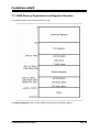
3.17 RAM Memory Organization and Register Allocation .............................................................. 130
3.18 Using an External Startup Assembly File ............................................................................... 133
3.19 Including Assembly Language in Your Program .................................................................... 135
3.19.1 Calling Assembly Functions from C................................................................................ 136
3.20 Creating Libraries ................................................................................................................... 137
3.21 Using the AVR Studio Debugger ............................................................................................ 140
3.22 Compiling the Sample Code of the ATxmega Application Notes from Atmel ........................ 141
3.23 Hints........................................................................................................................................ 141
3.24 Limitations............................................................................................................................... 141
4. Library Functions Reference........................................................................................................ 142
4.1 Character Type Functions ........................................................................................................ 143
4.2 Standard C Input/Output Functions.......................................................................................... 144
4.3 Standard Library Functions ...................................................................................................... 152
4.4 Mathematical Functions............................................................................................................ 154
4.5 String Functions........................................................................................................................ 157
4.6 Variable Length Argument Lists Macros .................................................................................. 162
4.7 Non-local Jump Functions ........................................................................................................ 163
© 1998-2010 HP InfoTech S.R.L.
Page 5
CodeVisionAVR
4.8 BCD Conversion Functions ...................................................................................................... 165
4.9 Gray Code Conversion Functions ............................................................................................ 165
4.10 Memory Access Macros ......................................................................................................... 166
4.11 LCD Functions ........................................................................................................................ 167
4.11.1 LCD Functions for displays with up to 2x40 characters ................................................. 167
4.11.2 LCD Functions for displays with 4x40 characters .......................................................... 170
4.11.3 LCD Functions for displays connected in 8 bit memory mapped mode ......................... 172
4.12 I2C Bus Functions ................................................................................................................... 174
4.12.1 National Semiconductor LM75 Temperature Sensor Functions .................................... 176
4.12.2 Maxim/Dallas Semiconductor DS1621 Thermometer/ Thermostat Functions ............... 179
4.12.3 Philips PCF8563 Real Time Clock Functions................................................................. 182
4.12.4 Philips PCF8583 Real Time Clock Functions................................................................. 185
4.12.5 Maxim/Dallas Semiconductor DS1307 Real Time Clock Functions............................... 188
4.13 Two Wire Interface Functions for ATxmega Devices ............................................................. 190
4.13.1 Two Wire Interface Functions for Master Mode Operation............................................. 191
4.13.2 Two Wire Interface Functions for Slave Mode Operation............................................... 195
4.14 Maxim/Dallas Semiconductor DS1302 Real Time Clock Functions....................................... 201
4.15 1 Wire Protocol Functions ...................................................................................................... 203
4.15.1 Maxim/Dallas Semiconductor DS1820/DS18S20 Temperature Sensors Functions...... 206
4.15.2 Maxim/Dallas Semiconductor DS18B20 Temperature Sensor Functions...................... 210
4.15.3 Maxim/Dallas Semiconductor DS2430 EEPROM Functions.......................................... 213
4.15.4 Maxim/Dallas Semiconductor DS2433 EEPROM Functions.......................................... 216
4.16 SPI Functions ......................................................................................................................... 219
4.17 Power Management Functions............................................................................................... 223
4.18 Delay Functions...................................................................................................................... 225
4.19 MMC/SD/SD HC FLASH Memory Card Driver Functions...................................................... 226
4.20 FAT Access Functions............................................................................................................ 235
5. CodeWizardAVR Automatic Program Generator ....................................................................... 261
© 1998-2010 HP InfoTech S.R.L.
Page 6
CodeVisionAVR
5.1 Setting the AVR Chip Options .................................................................................................. 265
5.2 Setting the External SRAM....................................................................................................... 267
5.3 Setting the Input/Output Ports .................................................................................................. 269
5.4 Setting the External Interrupts .................................................................................................. 270
5.5 Setting the Timers/Counters..................................................................................................... 272
5.6 Setting the UART or USART .................................................................................................... 278
5.7 Setting the Analog Comparator ................................................................................................ 281
5.8 Setting the Analog-Digital Converter ........................................................................................ 283
5.9 Setting the ATmega406 Voltage Reference............................................................................. 285
5.10 Setting the ATmega406 Coulomb Counter ............................................................................ 286
5.11 Setting the SPI Interface......................................................................................................... 288
5.12 Setting the Universal Serial Interface - USI............................................................................ 289
5.13 Setting the I2C Bus ................................................................................................................. 291
5.13.1 Setting the LM75 devices ............................................................................................... 292
5.13.2 Setting the DS1621 devices ........................................................................................... 293
5.13.3 Setting the PCF8563 devices ......................................................................................... 294
5.13.4 Setting the PCF8583 devices ......................................................................................... 295
5.13.5 Setting the DS1307 devices ........................................................................................... 296
5.14 Setting the 1 Wire Bus............................................................................................................ 298
5.15 Setting the Two Wire Bus Interface........................................................................................ 300
5.16 Setting the Two Wire Bus Slave Interface.............................................................................. 301
5.17 Setting the CAN Controller ..................................................................................................... 303
5.18 Setting the ATmega169/329/3290/649/6490 LCD Controller................................................. 305
5.19 Setting the LCD ...................................................................................................................... 306
5.20 Setting the USB Controller ..................................................................................................... 307
5.21 Setting Bit-Banged Peripherals .............................................................................................. 308
5.22 Specifying the Project Information.......................................................................................... 309
6. CodeWizardAVR Automatic Program Generator for the ATxmega Chips............................... 310
© 1998-2010 HP InfoTech S.R.L.
Page 7
CodeVisionAVR
6.1 Setting the General Chip Options............................................................................................. 315
6.2 Setting the System Clocks........................................................................................................ 317
6.3 Setting the Event System ......................................................................................................... 322
6.4 Setting the Input/Output Ports .................................................................................................. 323
6.5 Setting the Virtual Ports............................................................................................................ 325
6.6 Setting the Timers/Counters..................................................................................................... 326
6.7 Setting the Watchdog Timer ..................................................................................................... 333
6.8 Setting the 16-Bit Real Time Counter....................................................................................... 334
6.9 Setting the 32-Bit Real Time Counter and Battery Backup System ......................................... 336
6.10 Setting the USARTs ............................................................................................................... 338
6.11 Setting the Serial Peripheral Interfaces.................................................................................. 343
6.12 Setting the 1 Wire Bus............................................................................................................ 345
6.13 Setting the Two Wire Interfaces ............................................................................................. 346
6.14 Specifying the Project Information.......................................................................................... 348
7. License Agreement ....................................................................................................................... 349
7.1 Software License ...................................................................................................................... 349
7.2 Liability Disclaimer .................................................................................................................... 349
7.3 Restrictions ............................................................................................................................... 349
7.4 Operating License .................................................................................................................... 349
7.5 Back-up and Transfer ............................................................................................................... 350
7.6 Terms........................................................................................................................................ 350
7.7 Other Rights and Restrictions................................................................................................... 350
8. Technical Support and Updates .................................................................................................. 351
9. Contact Information ...................................................................................................................... 352
© 1998-2010 HP InfoTech S.R.L.
Page 8
CodeVisionAVR
1. Introduction
CodeVisionAVR is a C cross-compiler, Integrated Development Environment and Automatic Program
Generator designed for the Atmel AVR family of microcontrollers.
The program is designed to run under the 2000, XP, Vista and Windows 7 32bit and 64bit operating
systems.
The C cross-compiler implements all the elements of the ANSI C language, as allowed by the AVR
architecture, with some features added to take advantage of specificity of the AVR architecture and
the embedded system needs.
The compiled COFF object files can be C source level debugged, with variable watching, using the
Atmel AVR Studio debugger.
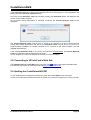
The Integrated Development Environment (IDE) has built-in AVR Chip In-System Programmer
software that enables the automatic transfer of the program to the microcontroller chip after successful
compilation/assembly. The In-System Programmer software is designed to work in conjunction with
the Atmel STK500, STK600, AVRISP, AVRISP MkII, AVR Dragon, JTAGICE MkII, AVRProg (AVR910
application note), Kanda Systems STK200+, STK300, Dontronics DT006, Vogel Elektronik VTEC-ISP,
Futurlec JRAVR and MicroTronics' ATCPU, Mega2000 development boards.
For debugging embedded systems, which employ serial communication, the IDE has a built-in
Terminal.
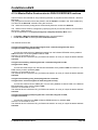
Besides the standard C libraries, the CodeVisionAVR C compiler has dedicated libraries for:
• Alphanumeric LCD modules
• Philips I2C bus
• National Semiconductor LM75 Temperature Sensor
• Philips PCF8563, PCF8583, Maxim/Dallas Semiconductor DS1302 and DS1307 Real Time
Clocks
• Maxim/Dallas Semiconductor 1 Wire protocol
• Maxim/Dallas Semiconductor DS1820, DS18S20 and DS18B20 Temperature Sensors
• Maxim/Dallas Semiconductor DS1621 Thermometer/Thermostat
• Maxim/Dallas Semiconductor DS2430 and DS2433 EEPROMs
• SPI
• Power management
• Delays
• Gray code conversion
• MMC/SD/SD HC FLASH memory cards low level access
• FAT acces on MMC/SD/SD HC FLASH memory cards.
CodeVisionAVR also contains the CodeWizardAVR Automatic Program Generator, that allows you to
write, in a matter of minutes, all the code needed for implementing the following functions:
• External memory access setup
• Chip reset source identification
• Input/Output Port initialization
• External Interrupts initialization
• Timers/Counters initialization
• Watchdog Timer initialization
• UART (USART) initialization and interrupt driven buffered serial communication
• Analog Comparator initialization
• ADC initialization
• SPI Interface initialization
• Two Wire Interface initialization
• CAN Interface initialization
• I2C Bus, LM75 Temperature Sensor, DS1621 Thermometer/Thermostat and PCF8563, PCF8583,
DS1302, DS1307 Real Time Clocks initialization
• 1 Wire Bus and DS1820/DS18S20 Temperature Sensors initialization
• LCD module initialization.
© 1998-2010 HP InfoTech S.R.L.
Page 9
CodeVisionAVR
This product is © Copyright 1998-2010 Pavel Haiduc and HP InfoTech S.R.L., all rights reserved.
The MMC, SD, SD HC and FAT File System libraries are based on the FatFS open source project
from http://elm-chan.org © Copyright 2006-2009 ChaN, all rights reserved.
1.1 Credits
The HP InfoTech team wishes to thank:
• Mr. Jack Tidwell for his great help in the implementation of the floating point routines
• Mr. Yuri G. Salov for his excellent work in improving the Mathematical Functions Library
• Mr. Olivier Wuillemin and Mr. Franc Marx for their help in beta testing
• Mr. Lee H. Theusch for his support in improving the compiler
• Mr. ChaN from Electronic Lives Mfg. http://elm-chan.org for the open source MMC/SD/SD HC
FLASH Memory Card Driver and FAT File System functions.
© 1998-2010 HP InfoTech S.R.L.
Page 10
CodeVisionAVR
2. The CodeVisionAVR Integrated Development Environment
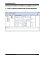
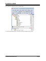
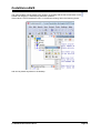
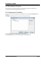
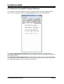
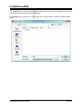
2.1 Using the Integrated Development Environment Workspace
The CodeVisionAVR IDE workspace consist from several windows that may be docked to the main
application window or left floating on the desktop to suit the user's preferences.
© 1998-2010 HP InfoTech S.R.L.
Page 11
CodeVisionAVR
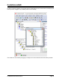
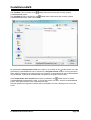
In order to undock a window, it's top bar must be clicked with the left mouse button and keeping the
button pressed, dragged to any suitable position on the desktop.
The window can be resized by dragging it's margins and corners with the left mouse button pressed.
© 1998-2010 HP InfoTech S.R.L.
Page 12
CodeVisionAVR
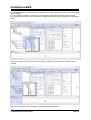
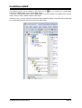
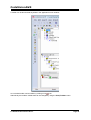
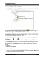
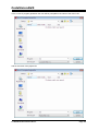
An undocked window can be docked to any position in the main application window or even to another
docked window.
In order to dock the window, it's top bar must be dragged, keeping the left mouse button pressed.
The possible dock locations of the window are outlined with special docking markers like in the picture
below:
When the mouse cursor arrives on one of the docking markers, the future docking position will be
outlined:
After the mouse button will be released, the window will become docked.
© 1998-2010 HP InfoTech S.R.L.
Page 13
CodeVisionAVR
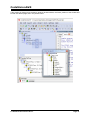
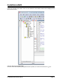
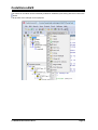
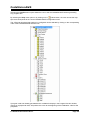
If the window is desired to be docked to another docked window, the future position of the window will
be that of a tabbed page, like in the picture below:
© 1998-2010 HP InfoTech S.R.L.
Page 14
CodeVisionAVR
Once docked, the window will become a tabbed page:
To undock a single tabbed page, the bottom tab must be dragged with the mouse.
© 1998-2010 HP InfoTech S.R.L.
Page 15
CodeVisionAVR
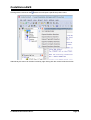
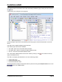
A workspace window can be hidden by left clicking on it's
icon, by pressing it's corresponding
button on the View toolbar or by using the View menu.
A window's corresponding button on the View toolbar must be pressed or the View menu must be
used in order to make a hidden window visible again.
Clicking on the
icon will make the docked window temporarily hidden, it's position will be displayed
by a vertical bar located on the left or right of the docking site:
© 1998-2010 HP InfoTech S.R.L.
Page 16
CodeVisionAVR
If the user will place the mouse cursor on the vertical bar, the hidden window will be displayed for a
short amount of time
and then will become hidden again.
In order to lock the temporarily displayed window in position, the user must click on the
© 1998-2010 HP InfoTech S.R.L.
icon.
Page 17
CodeVisionAVR
Clicking with the mouse on the
window icon will open a specific drop down menu:
Alternatively this menu can be also invoked by right clicking with the mouse inside the window.
© 1998-2010 HP InfoTech S.R.L.
Page 18
CodeVisionAVR
The menu toolbars can be placed to any position, by clicking with the left mouse button on the
handle and dragging it, while keeping the button pressed.
If the toolbar is moved outside the menu, it will become floating, like in the following picture:
and can be placed anywhere on the desktop.
© 1998-2010 HP InfoTech S.R.L.
Page 19
CodeVisionAVR
A toolbar can be also docked anywhere in the application's main window:
icon.
An undocked toolbar can be hidden by clicking on it's
Alternatively the toolbars' visible state can be changed by using the View|Toolbars menu.
© 1998-2010 HP InfoTech S.R.L.
Page 20
CodeVisionAVR
The buttons on a toolbar can be individually enabled or disabled by left clicking with the mouse on the
button.
A drop-down menu will open for this purpose:
© 1998-2010 HP InfoTech S.R.L.
Page 21
CodeVisionAVR
The visibility state of the toolbars can be also individually modified by right clicking with the mouse on
the button.
A drop-down menu will open for this purpose:
All the workspace layout will be automatically saved at program exit and restored back on the next
launch.
The Editor uses a tabbed multiple window interface.
The following key shortcuts are available:
• Ctrl+TAB - switch to the next editor tabbed window
• Ctrl+Shift+TAB - switch to the previous editor tabbed window
• Ctrl+W - close the current editor tabbed window.
The current editor tabbed window can be also closed by clicking on the
right of the tabbed control.
icon located on the top
The Editor can display the edited files in one of the following modes:
• Single Editor Pane
• Dual Vertical Editor Pane
• Dual Horizontal Editor Pane.
Switching between the above mentioned modes is performed using the View|File Panes menu or the
buttons of the View toolbar.
© 1998-2010 HP InfoTech S.R.L.
Page 22
CodeVisionAVR
In dual editor pane mode, the active pane is selected by left-clicking with the mouse on the pane's top
caption bar:
All File, Edit, Search menu operations will be performed on the active editor pane.
The editor panes can be resized by dragging the pane splitter with the mouse.
An editor pane can be maximized by double-clicking with the mouse left button on it's top caption bar.
By double-clicking once again, the pane is restored to it's original size.
© 1998-2010 HP InfoTech S.R.L.
Page 23
CodeVisionAVR
2.2 Working with Files
Using the CodeVisionAVR IDE you can view and edit any text file used or produced by the C compiler
or assembler.
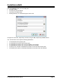
2.2.1 Creating a New File
You can create a new source file using the File|New menu command, by pressing the Ctrl+N keys or
button on the toolbar.
the
A dialog box appears, in which you must select File Type|Source and press the Ok button.
A new editor window appears for the newly created file.
The new file has the name untitled.c. You can save this file under a new name using the File|Save
toolbar button.
As menu command or the
© 1998-2010 HP InfoTech S.R.L.
Page 24
CodeVisionAVR
2.2.2 Opening an Existing File
You can open an existing file using the File|Open menu command, by pressing the Ctrl+O keys or the
button on the toolbar.
An Open dialog window appears.
You must select the name and type of file you wish to open.
By pressing the Open button you will open the file in a new editor window.
2.2.3 Files History
The CodeVisionAVR IDE keeps a history of the opened files.
The most recent eight files that where used can be reopened using the File|Reopen menu command
or the
toolbar button.
© 1998-2010 HP InfoTech S.R.L.
Page 25
CodeVisionAVR
2.2.4 Editing a File
A previously opened or a newly created file can be edited in the editor window by using the Tab,
Arrows, Backspace and Delete keys.
Pressing the Home key moves the cursor to the start of the current text line.
Pressing the End key moves the cursor to the end of the current text line.
Pressing the Ctrl+Home keys moves the cursor to the start of the file.
Pressing the Ctrl+End keys moves the cursor to the end of the file.
Portions of text can be selected by dragging with the mouse.
You can copy the selected text to the clipboard by using the Edit|Copy menu command, by pressing
the Ctrl+C keys or by pressing the
button on the toolbar.
button on
By using the Edit|Cut menu command, by pressing the Ctrl+X keys or by pressing the
the toolbar, you can copy the selected text to the clipboard and then delete it from the file.
Text previously saved in the clipboard can be placed at the current cursor position by using the
button on the toolbar.
Edit|Paste menu command, by pressing the Ctrl+V keys or pressing the
Clicking in the left margin of the editor window allows selection of a whole line of text.
Selected text can be deleted using the Edit|Delete menu command, by pressing the Ctrl+Delete keys
toolbar button.
or the
Dragging and dropping with the mouse can move portions of text.
Pressing the Ctrl+Y keys deletes the text line where the cursor is currently positioned.
Changes in the edited text can be undone, respectively redone, by using the Edit|Undo, respectively
Edit|Redo, menu commands, by pressing the Ctrl+Z, respectively Shift+Ctrl+Z keys, or by pressing
the , respectively
buttons on the toolbar.
Clicking with the mouse right button in the Editor window, opens a pop-up menu that gives access to
the above mentioned functions.
© 1998-2010 HP InfoTech S.R.L.
Page 26
CodeVisionAVR
2.2.4.1 Searching/Replacing Text
You can find, respectively replace, portions of text in the edited file by using the Search|Find,
respectively Search|Replace, menu commands, by pressing the Ctrl+F, respectively Ctrl+R keys, or
by pressing the , respectively
buttons on the toolbar.
The Search|Find Next, respectively Search|Find Previous, functions can be used to find the next,
respectively previous, occurrences of the search text.
The same can be achieved using the F3, respectively Ctrl+F3 keys or the , respectively the ,
toolbar buttons.
Searching, respectively replacing, portions of text in files can be performed using the Search|Find in
Files, respectively Search|Replace in Files, menu commands, by pressing the Ctrl+Shift+F,
buttons on the toolbar.
respectively Ctrl+Shift+H keys, or by pressing the , respectively
These functions are also available in the pop-up menu, invoked by mouse right clicking in the Editor
window.
2.2.4.2 Setting Bookmarks
Bookmarks can be inserted or removed, at the line where the cursor is positioned, by using the
toolbar
Edit|Toggle Bookmark menu command, by pressing the Shift+Ctrl+0...9 keys or the
button.
toolbar button will
The Edit|Jump to Bookmark menu command, the Ctrl+0...9 keys or the
position the cursor at the start of the corresponding bookmarked text line.
Jumping to the next bookmark can be achieved by using the Edit|Jump to Next Bookmark menu
toolbar button.
command, by pressing the F2 key or by using the
Jumping to the previous bookmark can be achieved by using the Edit|Jump to Previous Bookmark
toolbar button.
menu command, by pressing the Shift+F2 keys or by using the
toolbar
After a jump to a bookmark was performed, the Edit|Go Back menu command or the
button allow to return to the previous position in the file.
toolbar button allow to return to the file position
The Edit|Go Forward menu command or the
toolbar button were used.
before the Edit|Go Back menu command or the
These functions are also available in the pop-up menu, invoked by mouse right clicking in the Editor
window.
2.2.4.3 Jumping to a Symbol Definition or Declaration
When the editor cursor is located on a symbol name and the Edit|Go to Definition/Declaration menu
toolbar button are pressed, a jump will be performed to
command is performed, the F12 key or the
the symbol definition or declaration located in any of the project’s source files.
After a jump to the definition or declaration was performed, the Edit|Go Back menu command or the
toolbar button allow to return to the previous position in the edited file.
toolbar button allow to return to the file position
The Edit|Go Forward menu command or the
toolbar button were used.
before the Edit|Go Back menu command or the
These functions are also available in the pop-up menu, invoked by mouse right clicking in the Editor
window.
© 1998-2010 HP InfoTech S.R.L.
Page 27
CodeVisionAVR
2.2.4.4 Jumping to a Specific Line Number in the Edited File
You can go to a specific line number in the edited file, by using the Edit|Go to Line menu command,
toolbar button.
by pressing the Ctrl+G keys or the
toolbar
After a jump to a specific line was performed, the Edit|Go Back menu command or the
button allow to return to the previous position in the edited file.
toolbar button allow to return to the file position
The Edit|Go Forward menu command or the
toolbar button were used.
before the Edit|Go Back menu command or the
These functions are also available in the pop-up menu, invoked by mouse right clicking in the Editor
window.
2.2.4.5 Printing a Text Selection
Portions of text can be selected by dragging with the mouse.
toolbar button allows the printing of the selected
The Edit|Print Selection menu command or the
text.
This function is also available in the pop-up menu, invoked by mouse right clicking in the Editor
window.
2.2.4.6 Indenting/Unindenting a Text Selection
Portions of text can be selected by dragging with the mouse.
Selected portions of text can be indented, respectively unindented, using the Edit|Indent Selection,
respectively Edit|Unindent Selection, menu commands, by pressing the Ctrl+I, respectively Ctrl+U
, respectively
, toolbar buttons.
keys or the
These functions are also available in the pop-up menu, invoked by mouse right clicking in the Editor
window.
2.2.4.7 Commenting/Uncommenting a Text Selection
Portions of text can be selected by dragging with the mouse.
Selected portions of text can be commented, respectively uncommented, using the Edit|Comment
Selection, respectively Edit|Unindent Selection, menu commands, by pressing the Ctrl+[,
, respectively
, toolbar buttons.
respectively Ctrl+] keys or the
These functions are also available in the pop-up menu, invoked by mouse right clicking in the Editor
window.
2.2.4.8 Match Braces
If the cursor is positioned before an opening, respectively after a closing, brace then selecting the
toolbar button will position
Edit|Match Braces menu command, pressing the Ctrl+M keys or the
the cursor after, respectively before, the corresponding matching closing, respectively opening brace.
This function is also available in the pop-up menu, invoked by mouse right clicking in the Editor
window.
© 1998-2010 HP InfoTech S.R.L.
Page 28
CodeVisionAVR
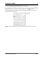
2.2.4.9 Inserting Special Characters in the Text
Special characters can be inserted in the edited text, at the cursor is position, by using the Edit|Insert
toolbar button.
Special Characters menu command, by pressing the Ctrl+. keys or the
A pop-up window containing a character map grid will be displayed, allowing the user to select the
appropriate character to be inserted:
This function is also available in the pop-up menu, invoked by mouse right clicking in the Editor
window.
© 1998-2010 HP InfoTech S.R.L.
Page 29
CodeVisionAVR
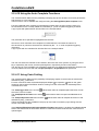
2.2.4.10 Using the Auto Complete Functions
The CodeVisionAVR Editor has the possibility to display pop-up hint windows for function parameters
and structure or union members.
These functions can be enabled and configured using the Settings|Editor|Auto Complete menu.
Function parameter auto complete is automatically invoked when the user types the name of a
function defined in the currently edited file, followed by a ‘(‘ auto completion triggering character.
A pop-up hint with parameter list will show like in the example below:
The parameter to be specified is highlighted with bold text.
Structure or union members auto complete is invoked after the user writes the name of a
structure/union or pointer to structure/union followed by the ‘.’ or ‘->’ auto completion triggering
characters.
A pop-up hint with the members list will show like in the example below:
The user can select the member to be inserted in the text at the cursor position, by using the arrow
keys, respectively the mouse, and then pressing Enter, respectively the left mouse button.
The structure or union members auto completion works only for global structures/unions defined in the
currently edited source file and after a Project|Compile or Project|Build was performed.
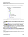
2.2.4.11 Using Code Folding
The CodeVisionAVR Editor has the possibility of displaying staples on the left side of code blocks
delimited by the { } characters.
For each code block there will be also displayed collapse or expansion marks on the gutter
located on the left side of the Editor window. Clicking on these marks allow to individually fold or
unfold blocks of code.
toolbar button allow to collapse/expand the block of code
The View|Toggle Fold menu and the
where the cursor is located.
toolbar button allow to expand all folded blocks of
The View|Expand All Folds menu and the
code.
toolbar button allow to collapse all blocks of code
The View|Collapse All Folds menu and the
delimited by the { } characters.
These commands are also available in the pop-up menu that is invoked by right clicking with the
mouse in the Editor window.
If the Settings|Editor|General|Visual Aids|Save Folded Lines option is enabled, the folded/unfolded
state of the code blocks is saved when the file is closed and it will be restored back, when the file is
opened again.
© 1998-2010 HP InfoTech S.R.L.
Page 30
CodeVisionAVR
2.2.5 Saving a File
The currently edited file can be saved by using the File|Save menu command, by pressing the Ctrl+S
button on the toolbar.
keys or by pressing the
When saving, the Editor will create a backup file with a ~ character appended to the extension.
All currently opened files can be saved using the File|Save All menu command, by pressing the
toolbar button.
Ctrl+Shift+S keys or the
2.2.6 Renaming a File
The currently edited file can be saved under a new name by using the File|Save As menu command
toolbar button.
or the
A Save As dialog window will open.
You will have the possibility to specify the new name and type of the file, and eventually its new
location.
© 1998-2010 HP InfoTech S.R.L.
Page 31
CodeVisionAVR
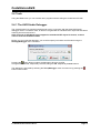
2.2.7 Printing a File
You can print the current file using the File|Print menu command or by pressing the
toolbar.
The contents of the file will be printed to the Windows default printer.
button on the
The paper margins used when printing can be set using the File|Page Setup menu command or the
toolbar button, which opens the Page Setup dialog window.
The units used when setting the paper margins are specified using the Units list box.
The printer can be configured by pressing the Printer button in this dialog window.
Changes can be saved, respectively canceled, using the OK, respectively Cancel buttons.
The print result can be previewed using the File|Print Preview menu command or by pressing the
toolbar button.
2.2.8 Closing a File
You can quit editing the current file by using the File|Close menu command, the Ctrl+F4 shortcut or
the toolbar button.
The current editor tabbed window can be also closed by clicking on the
icon located on the top
right of the tabbed control.
If the file was modified, and wasn't saved yet, you will be prompted if you want to do that.
Pressing Yes will save changes and close the file.
Pressing No will close the file without saving the changes.
Pressing Cancel will disable the file closing process.
© 1998-2010 HP InfoTech S.R.L.
Page 32
CodeVisionAVR
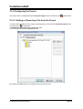
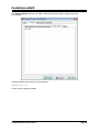
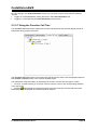
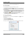
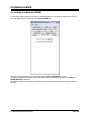
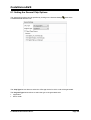
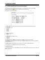
2.2.9 Closing Multiple Files
Closing several files can be performed using the File|Close Multiple menu command or the
toolbar button.
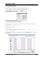
A dialog window, which lists all the opened files, will open for this purpose:
Files to be closed can be selected by checking the appropriate check boxes.
All the listed files can be selected using the Select All button.
The state of the check boxes can be reversed using the Invert Selection button.
The Clear Selection button can be used to un-check all the check boxes.
Pressing the OK button will close all the selected files from the list.
Pressing the Cancel button will close the dialog window, without closing any file.
© 1998-2010 HP InfoTech S.R.L.
Page 33
CodeVisionAVR
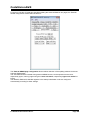
2.2.10 Using the Code Templates
The Code Templates window allows easy adding most often used code sequences to the currently
edited file.
This is achieved by clicking on the desired code sequence in the Code Templates window and then
dragging and dropping it to the appropriate position in the Editor window.
New code templates can be added to the list by dragging and dropping a text selection from the Editor
window to the Code Templates window.
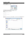
By right clicking in the Code Templates window you can open a pop-up menu with the following
choices:
• Copy to the Edit Window the currently selected code template
• Paste a text fragment from the clipboard to the Code Templates window
• Move Up in the list the currently selected code template
• Move Down in the list the currently selected code template
• Delete the currently selected code template from the list.
© 1998-2010 HP InfoTech S.R.L.
Page 34
CodeVisionAVR
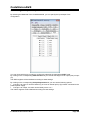
2.2.11 Using the Clipboard History
The Clipboard History window allows viewing and accessing text fragments that were recently copied
to the clipboard.
By right clicking in the Clipboard History window you can open a pop-up menu with the following
choices:
• Copy to the Edit Window the currently selected text fragment from the Clipboard History
window
• Delete the currently selected text fragment from the list
• Delete All the text fragments from the list.
© 1998-2010 HP InfoTech S.R.L.
Page 35
CodeVisionAVR
2.3 Working with Projects
The Project groups the source file(s) and compiler settings that you use for building a particular
program.
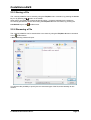
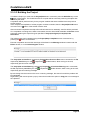
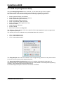
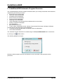
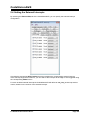
2.3.1 Creating a New Project
You can create a new Project using the File|New menu command or by pressing the button on the
toolbar.
A dialog box appears, in which you must select File Type|Project and press the OK button.
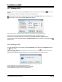
A dialog will open asking you to confirm if you would like to use the CodeWizardAVR to create the new
project.
If you select No then the Create New Project dialog window will open.
© 1998-2010 HP InfoTech S.R.L.
Page 36
CodeVisionAVR
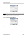
You must specify the new Project file name and its location.
The Project file will have the .prj extension.
You can configure the Project by using the Project|Configure menu command or by pressing the
toolbar button.
© 1998-2010 HP InfoTech S.R.L.
Page 37
CodeVisionAVR
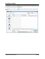
2.3.2 Opening an Existing Project
You can open an existing Project file using the File|Open menu command or by pressing the
button on the toolbar.
An Open dialog window appears.
You must select the file name of the Project you wish to open.
By pressing the Open button you will open the Project file and its source file(s).
You can later configure the Project by using the Project|Configure menu command or by pressing
toolbar button.
the
© 1998-2010 HP InfoTech S.R.L.
Page 38
CodeVisionAVR
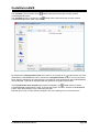
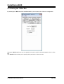
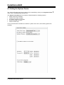
2.3.3 Adding Notes or Comments to the Project
With every Project the CodeVisionAVR IDE creates an associated text file where you can place notes
and comments.
You can access this file using the Project|Notes or Windows menu commands.
This file can be edited using the standard Editor commands.
The file is automatically saved when you Close the Project or Quit the CodeVisionAVR program.
© 1998-2010 HP InfoTech S.R.L.
Page 39
CodeVisionAVR
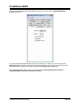
2.3.4 Configuring the Project
The Project can be configured using the Project|Configure menu command or the
toolbar button.
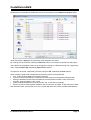
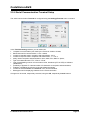
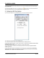
2.3.4.1 Adding or Removing a File from the Project
To add or remove a file from the currently opened project you must use the Project|Configure menu
toolbar button.
command or the
A Configure Project tabbed dialog window will open.
You must select the Files and Input Files tabs.
By pressing the Add button you can add a source file to the project.
© 1998-2010 HP InfoTech S.R.L.
Page 40
CodeVisionAVR
Multiple files can be added by holding the Ctrl key when selecting in the Add File to Project dialog.
When the project is Open-ed all project files will be opened in the editor.
By clicking on a file, and then pressing the Remove button, you will remove this file from the project.
The project's file compilation order can be changed by clicking on a file and moving it up, respectively
down, using the Move Up, respectively Move Down, buttons.
Changes can be saved, respectively canceled, using the OK, respectively Cancel buttons.
When creating a project with multiple files the following rules must be preserved:
• only .C files must be added to the project's Files list
• there's no need to #include the .C files from the Files list as they will be automatically linked
• data type definitions and function declarations must be placed in header .H files, that will be
#include -ed as necessary in the .C files
• global variables declarations must be placed in the .C files where necessary
• there's no need to declare global variables, that are not static, in header .H files, because if these
files will be #include -ed more than once, the compiler will issue errors about variable redeclarations.
© 1998-2010 HP InfoTech S.R.L.
Page 41
CodeVisionAVR
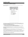
2.3.4.2 Setting the Project Output Directories
Selecting the Output Directories tab allows the user to specify distinct directories where will be
placed the files resulted after the compilation and linking.
Pressing the
button allows to select an existing directory.
The .rom and .hex files resulted after the Build process will be placed in the Executable Files
directory.
The object files resulted after the Compile process will be placed in the Object Files directory.
The COFF object file that results after the Build process will be also placed in the Object Files
directory.
The .asm, .lst and .map files created during the Build process will be placed in the List Files
directory.
Various files created by the linker during the Build process will be placed in the Linker Files directory.
© 1998-2010 HP InfoTech S.R.L.
Page 42
CodeVisionAVR
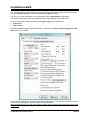
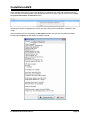
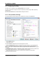
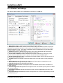
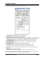
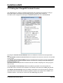
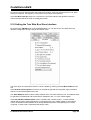
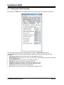
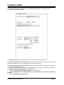
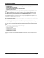
2.3.4.3 Setting the C Compiler Options
To set the C compiler options for the currently opened project you must use the Project|Configure
toolbar button.
menu command or the
A Configure Project tabbed dialog window will open. You must select the C Compiler and Code
Generation tabs.
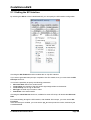
You can select the target AVR microcontroller chip by using the Chip combo box.
You must also specify the CPU Clock frequency in MHz, which is needed by the Delay Functions, 1
Wire Protocol Functions and Maxim/Dallas Semiconductor DS1820/DS18S20/DS18B20 Temperature
Sensors Functions.
The required memory model can be selected by using the Memory Model list box.
© 1998-2010 HP InfoTech S.R.L.
Page 43
CodeVisionAVR
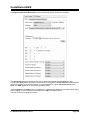
The compiled program can be optimized for minimum size, respectively maximum execution speed,
using the Optimize for|Size, respectively Optimize for|Speed, settings.
The amount of code optimization can be specified using the Optimization Level setting.
The Maximal optimization level may make difficult the code debugging with AVR Studio.
For devices that allow self-programming the Program Type can be selected as:
• Application
• Boot Loader
If the Boot Loader program type was selected, a supplementary Boot Loader Debugging in AVR
Studio option is available.
If this option is enabled, the compiler will generate supplementary code that allows the Boot Loader to
be source level debugged in the AVR Studio simulator/emulator.
When programming the chip with the final Boot Loader code, the Boot Loader Debugging option must
be disabled.
© 1998-2010 HP InfoTech S.R.L.
Page 44
CodeVisionAVR
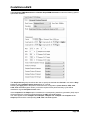
For reduced core chips like ATtiny10, there is an additional option: Enable auto Var. Watch in AVR
Studio.
If this option is enabled, the compiler will generate additional code that allows local automatic
variables, saved in the Data Stack, to be watched in AVR Studio 4.18 SP2 or later.
After finishing debugging the program, this option should be disabled and the project rebuild.
This will allow to reduce the size of the program and increase it's execution speed.
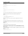
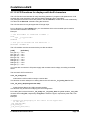
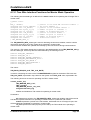
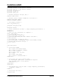
The (s)printf features option allows to select which versions of the printf and sprintf Standard C
Input/Oputput Functions will be linked in your project:
• int - the following conversion type characters are supported: 'c', 's', 'p', 'i', 'd', 'u', 'x', 'X', '%', no
width or precision specifiers are supported, only the '+' and ' ' flags are supported, no input size
modifiers are supported
• int, width - the following conversion type characters are supported: 'c', 's', 'p', 'i', 'd', 'u', 'x', 'X', '%',
the width specifier is supported, the precision specifier is not supported, only the '+', '-', '0' and ' ' flags
are supported, no input size modifiers are supported
• long, width - the following conversion type characters are supported: 'c', 's', 'p', 'i', 'd', 'u', 'x', 'X',
'%' the width specifier is supported, the precision specifier is not supported, only the '+', '-', '0' and ' '
flags are supported, only the 'l' input size modifier is supported
• long, width, precision - the following conversion type characters are supported: 'c', 's', 'p', 'i', 'd',
'u', 'x', 'X', '%', the width and precision specifiers are supported, only the '+', '-', '0' and ' ' flags are
supported, only the 'l' input size modifier is supported
• float, width, precision - the following conversion type characters are supported: 'c', 's', 'p', 'i', 'd',
'u', 'e', 'E', 'f', 'x', 'X', '%', the width and precision specifiers are supported, only the '+', '-', '0' and ' ' flags
are supported, only the 'l' input size modifier is supported.
The more features are selected, the larger is the code size generated for the printf and sprintf
functions.
The (s)scanf features option allows to select which versions of the scanf and sscanf Standard C
Input/Oputput Functions will be linked in your project:
• int, width - the following conversion type characters are supported: 'c', 's', 'i', 'd', 'u', 'x', '%', the
width specifier is supported, no input size modifiers are supported
• long, width - the following conversion type characters are supported: 'c', 's', 'i', 'd', 'u', 'x', '%' the
width specifier is supported, only the 'l' input size modifier is supported.
The more features are selected, the larger is the code size generated for the scanf and sscanf
functions.
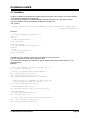
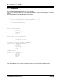
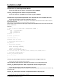
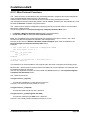
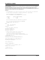
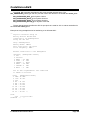
The Data Stack Size must be also specified.
If the dynamic memory allocation functions from the Standard Library are to be used, the Heap Size
must be also specified.
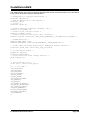
It can be calculated using the following formulae:
n
heap _ size = ( n + 1) ⋅ 4 + ∑ block _ sizei
i =1
where: n is the number of memory blocks that will be allocated in the heap
block _ sizei is the size of the memory block i
If the memory allocation functions will not be used, then the Heap Size must be specified as zero.
Eventually you may also specify the External RAM Size (in case the microcontroller have external
SRAM memory connected).
© 1998-2010 HP InfoTech S.R.L.
Page 45
CodeVisionAVR
The External RAM Wait State option enables the insertion of wait states during access to the external
RAM. This is useful when using slow memory devices.
If an Atmel AT94K05, AT94K10, AT94K20 or AT94K40 FPSLIC device will be used, than there will be
the possibility to specify the Program RAM Size in Kwords.
The maximum size of the global bit variables, which are placed in the GPIOR (if present) and registers
R2 to R14, can be specified using the Bit Variables Size list box.
The Use GPIOR >31 option, when checked, allows using GPIOR located at addresses above 31 for
global bit variables.
Note that bit variables located in GPIOR above address 31 are accessed using the IN, OUT, OR ,
AND instructions, which leads to larger and slower code than for bit variables located in GPIOR with
the address range 0…31, which use the SBI, CBI instructions. Also the access to bit variables located
in GPIOR above address 31 is not atomic.
Therefore it is recommended to leave the Use GPIOR >31 option not checked if the number of global
bit variables is small enough and no additional registers are needed for their storage.
© 1998-2010 HP InfoTech S.R.L.
Page 46
CodeVisionAVR
Checking the Promote char to int check box enables the ANSI promotion of char operands to int.
This option can also be specified using the #pragma promotechar compiler directive.
Promoting char to int leads to increases code size and lowers speed for an 8 bit chip microcontroller
like the AVR.
In order to assure code compatibility with other C compilers, the Promote char to int option is
enabled by default for newly created projects.
If the char is unsigned check box is checked, the compiler treats by default the char data type as an
unsigned 8 bit in the range 0…255.
If the check box is not checked the char data type is by default a signed 8 bit in the range –128…127.
This option can also be specified using the #pragma uchar compiler directive.
Treating char as unsigned leads to better code size and speed.
If the 8 bit enums check box is checked, the compiler treats the enumerations as being of 8 bit char
data type, leading to improved code size and execution speed of the compiled program. If the check
box is not checked the enumerations are considered as 16 bit int data type as required by ANSI.
The Enhanced Instructions check box allows enabling or disabling the generation of Enhanced Core
instructions for the new ATmega and AT94K FPSLIC devices.
The Smart Register Allocation check box enables allocation of registers R2 to R14 (not used for bit
variables) and R16 to R21 in such a way that 16bit variables will be preferably located in even register
pairs, thus favouring the usage of the enhanced core MOVW instruction for their access. This option is
effective only if the Enhanced Instructions check box is also checked.
If Smart Register Allocation is not enabled, the registers will be allocated in the order of variable
declaration.
The Smart Register Allocation option should be disabled if the program was developed using
CodeVisionAVR prior to V1.25.3 and it contains inline assembly code that accesses the variables
located in registers R2 to R14 and R16 to R21.
The registers in the range R2 to R14, not used for bit variables, can be automatically allocated to char
and int global variables and global pointers by checking the Automatic Global Register Allocation
check box.
If the Store Global Constants in FLASH Memory check box is checked, the compiler will treat the
const type qualifier as equivalent to the flash memory attribute and will place the constants in FLASH
memory. If the option is not checked, constants marked with the const type qualifier will be stored in
RAM memory and the ones marked with the flash memory attribute will be stored in FLASH memory.
The Store Global Constants in FLASH Memory option is, by default, not enabled for newly created
projects.
In order to maintain compatibility with V1.xx projects, the Store Global Constants in FLASH Memory
option must be checked.
An external startup.asm file can be used by checking the Compilation|Use an External Startup File
check box.
The Clear Global Variables at Program Startup check box allows enabling or disabling the
initialization with zero of global variables located in RAM and registers R2 to R14 at program startup
after a chip reset. If an external startup.asm file is used, this option must signal to the compiler if the
variable initialization with zero is performed in this file or not.
For debugging purposes you have the option Stack End Markers. If you select it, the compiler will
place the strings DSTACKEND, respectively HSTACKEND, at the end of the Data Stack, respectively
Hardware Stack areas.
When you debug the program with the AVR Studio debugger you may see if these strings are
overwritten, and consequently modify the Data Stack Size.
When your program runs correctly you may disable the placement of the strings in order to reduce
code size.
© 1998-2010 HP InfoTech S.R.L.
Page 47
CodeVisionAVR
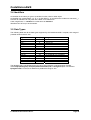
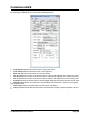
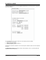
Using the File Output Format(s) list box you can select the following formats for the files generated
by the compiler:
• COFF (required by the Atmel AVR Studio debugger), ROM, Intel HEX and EEP (required by the
In-System Programmer) ;
• Atmel generic OBJ, ROM, Intel HEX and EEP (required by the In-System Programmer).
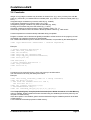
The following Preprocessor options can be set:
• Create Preprocessor Output Files - when enabled, an additional file with the .i extension will be
created for each compiled source file. The preprocessor output files will contain the source files
text will all the preprocessor macros expanded. Enabling this option will slow down the compilation
process.
• Include I/O Registers Bits Definitions - will enable the I/O register bits definitions in the device
header files.
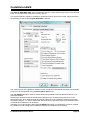
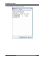
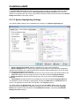
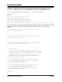
The Advanced tab, which is present only in the Advanced and Professional versions of the compiler,
enables more detailed custom configuration like the number and jump type of the interrupt vectors and
memory usage:
The Int. Vectors in External File option enables or disables placing the interrupt vectors in an
external vectors.asm file created by the user. If this option is enabled the compiler will not generate
any interrupt vectors by itself as the vectors will be present in the vectors.asm file.
© 1998-2010 HP InfoTech S.R.L.
Page 48
CodeVisionAVR
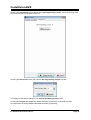
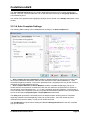
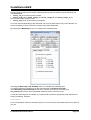
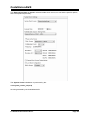
The Libraries tab is used for configuring specific driver libraries used by the compiler.
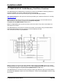
The 1 Wire tab is used for configuring the I/O port allocation for the 1 Wire Protocol Functions.
The following settings are available:
• Enable 1 Wire Bus Interface Support allows the activation of the 1 Wire Protocol Functions
• I/O Port and Bit specify in Data Connection, the port and bit used for 1 Wire bus communication.
© 1998-2010 HP InfoTech S.R.L.
Page 49
CodeVisionAVR
The MMC/SD/SD HC Card tab is used for configuring the I/O port allocation for the MMC/SD/SD HC
FLASH Memory Card Driver Functions.
The Enable MMC/SD/SD HC Card and FAT Support check box activates the appropriate FLASH
Memory Card Drivers and FAT Access Functions libraries.
The SPI Slow Clock options allows to use a two times slower data rate when communicating with the
MMC/SD/SD HC Card in order to provide better compatibility with some hardware designs.
The WP Active Low option ensures compatibility with hardware designs which set the WP signal to
logic 0 when the MMC/SD/SD HC Card is write protected.
© 1998-2010 HP InfoTech S.R.L.
Page 50
CodeVisionAVR
The Messages tab allows to individually enable or disable various compiler and linker warnings:
The generation of warning messages during compilation can be globally enabled or disabled by using
the Enable Warnings check box.
© 1998-2010 HP InfoTech S.R.L.
Page 51
CodeVisionAVR
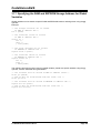
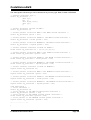
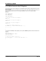
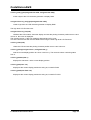
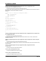
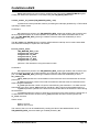
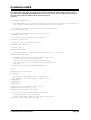
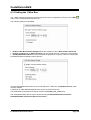
The Globally #define tab allows to #define macros that will be visible in all the project files.
For example:
will be equivalent with placing the macro definition:
#define ABC 1234
in each project's program module.
© 1998-2010 HP InfoTech S.R.L.
Page 52
CodeVisionAVR
The Paths tabs allows to specify additional paths for #include and library files.
These paths must be entered one per line in the appropriate edit controls.
Changes can be saved, respectively canceled, using the OK, respectively Cancel buttons.
© 1998-2010 HP InfoTech S.R.L.
Page 53
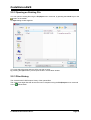
CodeVisionAVR
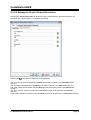
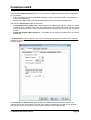
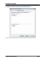
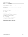
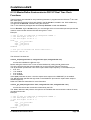
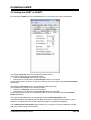
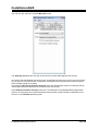
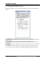
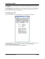
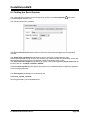
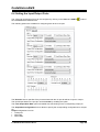
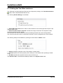
2.3.4.4 Executing an User Specified Program before Build
This option is available if you select the Before Build tab in the Project Configure window.
If you check the Execute User's Program option, then a program, that you have previously specified,
will be executed before the compilation/assembly process.
The following parameters can be specified for the program to be executed:
• Program Directory and File Name
• Program Command Line Parameters
• Program Working Directory.
© 1998-2010 HP InfoTech S.R.L.
Page 54
CodeVisionAVR
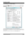
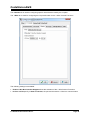
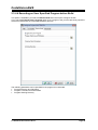
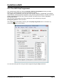
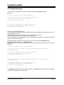
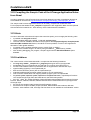
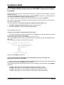
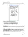
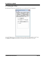
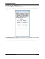
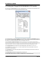
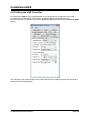
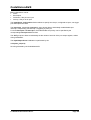
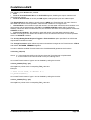
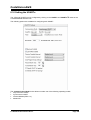
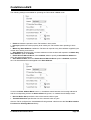
2.3.4.5 Transferring the Compiled Program to the AVR Chip after
Build
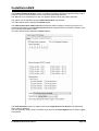
This option is available if you select the After Build tab in the Project Configure window.
If you check the Program the Chip option, then after successful compilation/assembly your program
will be automatically transferred to the AVR chip using the built-in Programmer software.
The following steps are executed automatically:
• Chip erasure
• FLASH and EEPROM blank check
• FLASH programming and verification
• EEPROM programming and verification
• Fuse and Lock Bits programming
© 1998-2010 HP InfoTech S.R.L.
Page 55
CodeVisionAVR
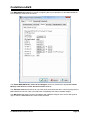
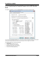
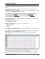
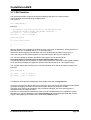
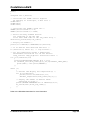
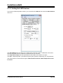
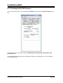
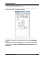
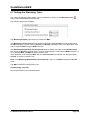
The Merge data from a .ROM File for FLASH Programming option, if checked, will merge in the
FLASH programming buffer the contents of the .ROM file, created by the compiler after Make, with the
data from the .ROM file specified in .ROM File Path.
This is useful, for example, when adding a boot loader executable compiled in another project, to an
application program that will be programmed in the FLASH memory.
You can select the type of the chip you wish to program using the Chip combo box.
The SCK clock frequency used for In-System Programming with the STK500, AVRISP or AVRISP MkII
can be specified using the SCK Freq. listbox. This frequency must not exceed ¼ of the chip's clock
frequency.
If the chip you have selected has Fuse Bit(s) that may be programmed, then a supplementary
Program Fuse Bit(s) check box will appear.
If it is checked, than the chip's Fuse Bit(s) will be programmed after Build.
The Fuse Bit(s) can set various chip options, which are described in the Atmel data sheets.
If a Fuse Bit(s) check box is checked, then the corresponding fuse bit will be set to 0, the fuse being
considered as programmed (as per the convention from the Atmel data sheets).
If a Fuse Bits(s) check box is not checked, then the corresponding fuse bit will be set to 1, the fuse
being considered as not programmed.
If you wish to protect your program from copying, you must select the corresponding option using the
FLASH Lock Bits radio box.
If you wish to check the chip's signature before programming you must use the Check Signature
option.
To speed up the programming process you can uncheck the Check Erasure check box.
In this case there will be no verification of the correctness of the FLASH erasure.
The Preserve EEPROM checkbox allows preserving the contents of the EEPROM during chip
erasure.
To speed up the programming process you can uncheck the Verify check box.
In this case there will be no verification of the correctness of the FLASH and EEPROM programming.
Changes can be saved, respectively canceled, using the OK, respectively Cancel buttons.
© 1998-2010 HP InfoTech S.R.L.
Page 56
CodeVisionAVR
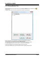
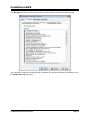
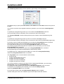
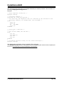
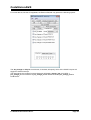
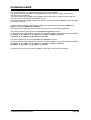
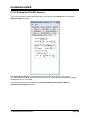
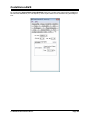
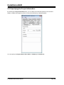
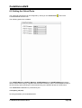
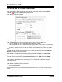
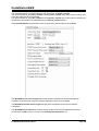
2.3.4.6 Executing an User Specified Program after Build
This option is available if you select the After Build tab in the Project Configure window.
If you check the Execute User's Program option, then a program, that you have previously specified,
will be executed after the compilation/assembly process.
© 1998-2010 HP InfoTech S.R.L.
Page 57
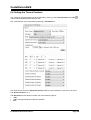
CodeVisionAVR
Using the Program Settings button you can modify the:
• Program Directory and File Name
• Program Command Line Parameters
• Program Working Directory
button allows to select a directory and file.
Pressing the
Changes can be saved, respectively canceled, using the OK, respectively Cancel buttons.
© 1998-2010 HP InfoTech S.R.L.
Page 58
CodeVisionAVR
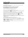
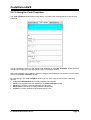
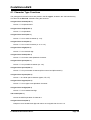
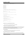
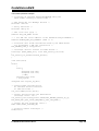
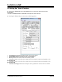
2.3.5 Obtaining an Executable Program
Obtaining an executable program requires the following steps:
1. Compiling the Project's C program modules, using the CodeVisionAVR C Compiler, and obtaining
object files needed by the linker
2. Linking the object files files created during compilation and obtaining a single assembler source
file
3. Assembling the assembler source file, using the Atmel AVR assembler AVRASM2.
Compiling, executes step 1.
Building, executes step 1, 2 and 3.
Compilation is performed only for the program modules that were modified since the previous similar
process.
This leads to significant project build reduction times, compared with the old CodeVisionAVR V1.xx,
where all the program modules were compiled even if they were not changed.
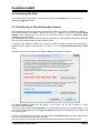
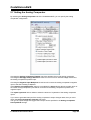
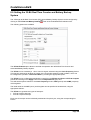
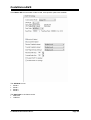
2.3.5.1 Checking Syntax
Checking the currently edited source file for syntax errors can be performed by using the
toolbar button.
Project|Check Syntax menu or by pressing the
This function is useful because it's faster than Project|Compile menu command, which compiles all
the modified files in a project.
It can also be executed by selecting Check Syntax in the pop-up menu, which is invoked by right
clicking with the mouse in the editor window.
© 1998-2010 HP InfoTech S.R.L.
Page 59
CodeVisionAVR
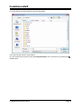
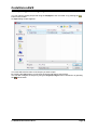
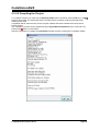
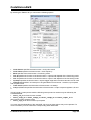
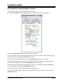
2.3.5.2 Compiling the Project
To compile the Project you must use the Project|Compile menu command, press the F9 key or the
button of the toolbar. The CodeVisionAVR C Compiler will be executed, producing the object files
needed by the linker.
Compilation will be performed only for the program modules that were modified since the previous
similar process.
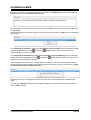
The compilation process can be stopped using the Project|Stop Compilation menu command or by
pressing the button on the toolbar.
After the compilation is complete, an Information window will open, showing the compilation results.
© 1998-2010 HP InfoTech S.R.L.
Page 60
CodeVisionAVR
Eventual compilation errors and/or warnings will be listed in the Message window located under the
Editor window, or in the Code Navigator window.
By left clicking with the mouse on the error or warning message, the source line with the problem will
be highlighted.
Right clicking with mouse opens a pop-up menu that contains the option to Copy the error message to
the clipboard:
The Project|Go to Next Error, respectively Project|Go to Previous Error menu commands, the F8,
toolbar buttons, allow moving to the next,
respectively Ctrl+F8 keys or the , respectively
respectively previous error message.
The Project|Go to Next Warning, respectively Project|Go to Previous Warning menu commands,
toolbar buttons, allow moving to the next,
the F4, respectively Ctrl+F4 keys or the , respectively
respectively previous warning message.
If the message refers also to a previous declaration or definition from a file that is different than the
one where the error was signaled, right clicking with the mouse opens a pop-up menu with the Jump
to Previous Declaration or Definition option:
Selecting this option will highlight the source line where the previous declaration or definition was
made.
The size of the Message window can be modified using the horizontal slider bar placed between it
and the Editor window.
© 1998-2010 HP InfoTech S.R.L.
Page 61
CodeVisionAVR
2.3.5.3 Building the Project
To build the Project you must use the Project|Build menu command, press the Shift+F9 keys or the
button of the toolbar. The CodeVisionAVR C Compiler will be executed, producing the object files
needed by the linker.
Compilation will be performed only for the program modules that were modified since the previous
similar process.
If the complete recompilation of all the program modules is needed, then the Project|Build All menu
command or the button of the toolbar must be used.
After successful compilation the object files will be linked and an assembly .asm file will be produced.
If no compilation or linking errors were encountered, then the Atmel AVR assembler AVRASM2 will be
executed, obtaining the output file types specified in Project|Configure|C Compiler|Code
Generation.
The build process can be stopped using the Project|Stop Compilation menu command or by
pressing the button on the toolbar.
Eventual compilation errors and/or warnings will be listed in the Message window located under the
Editor window, or in the Code Navigator window.
The Project|Go to Next Error, respectively Project|Go to Previous Error menu commands, the F8,
toolbar buttons, allow moving to the next,
respectively Ctrl+F8 keys or the , respectively
respectively previous error message.
The Project|Go to Next Warning, respectively Project|Go to Previous Warning menu commands,
toolbar buttons, allow moving to the next,
the F4, respectively Ctrl+F4 keys or the , respectively
respectively previous warning message.
By left clicking with the mouse on the error or warning message, the source line with the problem will
be highlighted.
Right clicking with mouse opens a pop-up menu that contains the option to Copy the error message to
the clipboard:
© 1998-2010 HP InfoTech S.R.L.
Page 62
CodeVisionAVR
If the message refers also to a previous declaration or definition from a file that is different than the
one where the error was signaled, right clicking with the mouse opens a pop-up menu with the Jump
to Previous Declaration or Definition option:
Selecting this option will highlight the source line where the previous declaration or definition was
made.
After the build process is completed, an Information window will open showing the build results.
Pressing the Compiler tab will display compilation results.
© 1998-2010 HP InfoTech S.R.L.
Page 63
CodeVisionAVR
Pressing the Assembler tab will display assembly results.
© 1998-2010 HP InfoTech S.R.L.
Page 64
CodeVisionAVR
Pressing the Programmer tab will display the Chip Programming Counter, which shows how many
times was the AVR chip programmed so far.
Pressing the Set Counter button will open the Set Programming Counter window:
This dialog window allows setting the new Chip Programming Counter value.
Pressing the Program the chip button allows automatic programming of the AVR chip after
successful build. Pressing Cancel will disable automatic programming.
© 1998-2010 HP InfoTech S.R.L.
Page 65
CodeVisionAVR
2.3.5.4 Cleaning Up the Project Output Directories
The various files created during the Project Build process can be deleted using the Project|Clean Up
button on the toolbar.
menu or by pressing the
The following Project Output Directories will be cleaned:
• Object Files directory - all files will be deleted, except the .cof COFF object file
• List Files directory - all files will be deleted, except the .asm and .vec assembly source files
• Linker Files directory – all files will be deleted.
© 1998-2010 HP InfoTech S.R.L.
Page 66
CodeVisionAVR
2.3.5.5 Using the Code Navigator
The Code Navigator window allows displaying or opening of the project source files, along with errors
or warnings that occured during the compile or build processes.
The project's program modules are listed as children of the Project node.
Other opened files, that are not part of the project, are listed as children of the Other Files
By clicking on a file node, the appropriate file is maximized or opened.
node.
After a Compile or Build process there is also displayed a list of header .h files that were #included in
the project's program modules during this process.
The headers files are available as children of the Headers node. By clicking on a header file
node, the appropriate header file is maximized or opened.
If during compilation there are errors or warnings, these are also displayed in the Code Navigator
window.
By clicking on the error or warning node, the corresponding source line is highlighted in the
appropriate file.
The Code Navigator tree branches can be expanded, respectively collapsed, by clicking on the +,
respectively -, buttons.
By right clicking in the Code Navigator window you can open a pop-up menu with the following
choices:
• Open a file
• Save the currently edited file
• Save All opened files
• Close currently edited file
• Close All opened files
• Toggle on or off alphabetically sorting the files in the Code Navigator
• Toggle on or off expanding the Errors and Warnings branches after a Compile or Build process
• Toggle on or off expanding the header file branches.
© 1998-2010 HP InfoTech S.R.L.
Page 67
CodeVisionAVR
2.3.5.6 Using the Code Information
The Code Information window allows for easy access to declarations and definitions made in the
currently edited source file.
The Code Information window is accessed using the tab with the same name and appears after the
first Compile or Build process of the currently opened project.
The information is displayed in the form of a tree with several types of nodes:
• Includes node which displays all the header .h files #included in the currently edited source file.
Clicking on a header node moves the cursor to the corresponding #include directive in the edited
source file.
• Macros node which displays all the preprocessor macros defined in the currently edited source
file. Clicking on a macro node moves the cursor to the corresponding #define directive in the edited
source file.
• Typedefs node which displays all the data types defined in the currently edited source file.
Clicking on a type definition node moves the cursor to the corresponding data type definition in the
edited source file. If the defined data type is a structure, union or enumeration, then it's members are
displayed as additional nodes.
• Global/Static Variables node which displays all the global and static variables declared in the
currently edited source file. Clicking on a RAM variable node or EEPROM variable node moves
the cursor to the corresponding declaration in the edited source file.
• Global Constants node which displays all the global constants declared in the currently edited
source file. Clicking on a constant node moves the cursor to the corresponding declaration in the
edited source file.
• Functions node which displays all the functions that were defined in the currently edited source
file. Clicking on a function node moves the cursor to the corresponding definition in the edited
source file.
The Code Information tree branches can be expanded, respectively collapsed, by clicking on the +,
respectively -, buttons.
© 1998-2010 HP InfoTech S.R.L.
Page 68
CodeVisionAVR
By right clicking in the Code Information window you can open a pop-up menu with the following
choices:
• Toggle on or off alphabetically sorting the items in the Code Information tree
• Toggle on or off expanding the Code Information tree branches.
2.3.5.7 Using the Function Call Tree
The Function Call Tree window displays the function call sequence that uses the largest amount of
Data Stack during program execution.
The Function Call Tree window is accessed using the tab with the same name and appears after the
first Compile or Build process of the currently opened project.
The Data Stack usage information is represented in the form of a tree with two types of nodes:
• Function nodes. Clicking on a function name moves the cursor to the corresponding definition
in the source file.
• DSTACK nodes display the data stack used by the parent function and the total level of the
Data Stack when the program is executed inside the function.
© 1998-2010 HP InfoTech S.R.L.
Page 69
CodeVisionAVR
2.3.6 Closing a Project
You can quit working with the current Project by using the File|Close Project menu command or the
toolbar button.
If the Project files were modified, and were not saved yet, you will be asked if you want to do that.
Pressing Yes will save changes and close the project.
Pressing No will close the project without saving the changes.
Pressing Cancel will disable the project closing process.
When saving, the IDE will create a backup file with a .prj~ extension.
© 1998-2010 HP InfoTech S.R.L.
Page 70
CodeVisionAVR
2.4 Tools
Using the Tools menu you can execute other programs without exiting the CodeVisionAVR IDE.
2.4.1 The AVR Studio Debugger
The CodeVisionAVR C Compiler is designed to work in conjunction with the Atmel AVR Studio
debugger version 4.18 SP2 or later, for which it will generate an extended COFF object file that allows
watching structures and unions.
Older versions of AVR Studio don't support the extended COFF object file format, so these
can't be used with CodeVisionAVR.
Before you can invoke the debugger, you must first specify its location and file name using the
Settings|Debugger menu command.
button allows to select the debugger's directory and file.
Pressing the
Changes can be saved, respectively canceled, using the OK, respectively Cancel buttons.
The debugger is executed by selecting the Tools|Debugger menu command or by pressing the
button on the toolbar.
© 1998-2010 HP InfoTech S.R.L.
Page 71
CodeVisionAVR
2.4.2 The AVR Chip Programmer
The CodeVisionAVR IDE has a built-in In-System AVR Chip Programmer that lets you easily
transfer your compiled program to the microcontroller for testing.
The Programmer is designed to work with the Atmel STK500, AVRISP, AVRISP MkII, AVR Dragon,
JTAGICE MkII, AVRProg (AVR910 application note), Kanda Systems STK200+, STK300, Dontronics
DT006, Vogel Elektronik VTEC-ISP, Futurlec JRAVR or the MicroTronics ATCPU, Mega2000
development boards.
The type of the used programmer and the printer port can be selected by using the
Settings|Programmer menu command.
The Programmer is executed by selecting the Tools|Chip Programmer menu command or by
pressing the
button on the toolbar.
You can select the type of the chip you wish to program using the Chip combo box.
© 1998-2010 HP InfoTech S.R.L.
Page 72
CodeVisionAVR
The SCK clock frequency used for In-System Programming with the STK500, AVRISP or AVRISP MkII
can be specified using the SCK Freq. listbox. This frequency must not exceed ¼ of the chip's clock
frequency.
If the chip you have selected has Fuse Bit(s) that may be programmed, then a supplementary
Program Fuse Bit(s) check box will appear.
If it is checked, than the chip's Fuse Bit(s) will be programmed when the Program|All menu command
is executed or when the
Program All button is pressed.
The Fuse Bit(s) can set various chip options, which are described in the Atmel data sheets.
If a Fuse Bit(s) check box is checked, then the corresponding fuse bit will be set to 0, the fuse being
considered as programmed (as per the convention from the Atmel data sheets).
If a Fuse Bits(s) check box is not checked, then the corresponding fuse bit will be set to 1, the fuse
being considered as not programmed.
If you wish to protect your program from copying, you must select the corresponding option using the
FLASH Lock Bits radio box.
The Programmer has two memory buffers:
• The FLASH memory buffer
• The EEPROM memory buffer.
You can Load or Save the contents of these buffers using the File menu.
Supported file formats are:
• Atmel .rom and .eep
• Intel HEX
• Binary .bin
After loading a file in the corresponding buffer, the Start and End addresses are updated accordingly.
You may also edit these addresses if you wish.
The contents of the FLASH, respectively EEPROM, buffers can be displayed and edited using the
Edit|FLASH , respectively Edit|EEPROM menu commands.
When one of these commands is invoked, an Edit window displaying the corresponding buffer
contents will open:
The buffer's contents, at the highlighted address, can be edited by pressing the F2 key and typing in
the new value. The edited value is saved by pressing the Tab or arrow keys.
The highlighted address can be modified using the arrow, Tab, Shift+Tab, PageUp or PageDown
keys.
© 1998-2010 HP InfoTech S.R.L.
Page 73
CodeVisionAVR
The Fill Memory Block window can be opened by right clicking in the Edit window:
This window lets you specify the Start Address, End Address and Fill Value of the memory area to
be filled.
If you wish to check the chip's signature before any operation you must use the Check Signature
option.
To speed up the programming process you can uncheck the Check Erasure check box.
In this case there will be no verification of the correctness of the FLASH erasure.
The Preserve EEPROM checkbox allows preserving the contents of the EEPROM during chip
erasure.
To speed up the programming process you also can uncheck the Verify check box.
In this case there will be no verification of the correctness of the FLASH and EEPROM programming.
For erasing a chip's FLASH and EEPROM you must select the Program|Erase menu command.
After erasure the chip's FLASH and EEPROM are automatically blank checked.
For simple blank checking you must use the Program|Blank Check menu command.
If you wish to program the FLASH with the contents of the FLASH buffer you must use the
Program|FLASH menu command.
For programming the EEPROM you must use the Program|EEPROM menu command.
After programming the FLASH and EEPROM are automatically verified.
To program the Lock, respectively the Fuse Bit(s) you must use the Program|Fuse Bit(s),
respectively Program|Lock Bits menu commands.
The Program|All menu command allows to automatically:
• Erase the chip
• FLASH and EEPROM blank check
• Program and verify the FLASH
• Program and verify the EEPROM
• Program the Fuse and Lock Bits.
If you wish to read the contents of the chip's FLASH, respectively EEPROM, you must use the
Read|FLASH, respectively Read|EEPROM menu commands.
For reading the chip's signature you must use the Read|Chip Signature menu command.
To read the Lock, respectively the Fuse Bits you must use the Read|Lock Bits,
respectively Read|Fuse Bits menu commands.
For some devices there's also the Read|Calibration Byte(s) option available.
It allows reading the value of the calibration bytes of the chip's internal RC oscillator.
© 1998-2010 HP InfoTech S.R.L.
Page 74
CodeVisionAVR
If the programmer is an Atmel STK500, AVRISP, AVRISP MkII or AVRProg (AVR910 application
note), then an additional menu command is present: Read|Programmer's Firmware Version. It
allows reading the major and minor versions of the above mentioned programmers' firmware.
For comparing the contents of the chip's FLASH, respectively EEPROM, with the corresponding
memory buffer, you must use the Compare|FLASH, respectively Compare|EEPROM menu
commands.
For exiting the Programmer and returning to the CodeVisionAVR IDE you must use the File|Close
menu command.
2.4.3 The Serial Communication Terminal
The Terminal is intended for debugging embedded systems, which employ serial communication
(RS232, RS422, RS485).
The Terminal is invoked using the Tools|Terminal menu command or the
button on the toolbar.
The characters can be displayed in ASCII or hexadecimal format. The display mode can be toggled
using the Hex/ASCII button.
The received characters can be saved to a file using the Rx File button.
Any characters typed in the Terminal window will be transmitted through the PC serial port.
The entered characters can be deleted using the Backspace key.
By pressing the Send button, the Terminal will transmit a character whose hexadecimal ASCII code
value is specified in the Hex Code edit box.
By pressing the Tx File button, the contents of a file can be transmitted through the serial port.
By pressing the Reset button, the AVR chip on the STK200+/300, VTEC-ISP, DT006, ATCPU or
Mega2000 development board is reseted.
At the bottom of the Terminal window there is a status bar in which are displayed the:
• computer's communication port;
• communication parameters;
• handshaking mode;
• received characters display mode;
• type of emulated terminal;
• the state of the transmitted characters echo setting.
© 1998-2010 HP InfoTech S.R.L.
Page 75
CodeVisionAVR
2.4.4 Executing User Programs
User programs are executed by selecting the corresponding command from the Tools menu.
You must previously add the Program's name to the menu.
2.4.5 Configuring the Tools Menu
You can add or remove User Programs from the Tools menu by using the Tools|Configure menu
command.
A Configure Tools dialog window, with a list of User Programs, will open.
Using the Add button you can add a Program to the Tools menu.
Using the Remove button you can remove a Program from the Tools menu.
© 1998-2010 HP InfoTech S.R.L.
Page 76
CodeVisionAVR
Using the Settings button you can modify the:
• Tool Menu Name
• Tool Directory and File Name
• Command Line Parameters
• Working Directory of a selected Program from the list
Changes can be saved, respectively canceled, using the OK, respectively Cancel buttons.
The command line can accept the following parameters:
•
•
•
•
•
•
%P substitutes the full project path
%p substitutes the project name without path
%h substitutes the name of the .hex file created by the compiler
%e substitutes the name of the .eep file created by the compiler
%f<project_file_number> substitutes the project’s source file name without path
%F<project_file_number> substitutes the project’s source file name with full path.
© 1998-2010 HP InfoTech S.R.L.
Page 77
CodeVisionAVR
2.5 IDE Settings
The CodeVisionAVR IDE is configured using the View and Settings menus.
2.5.1 The View Menu
The following settings can be configured using the View menu command:
• The View|Visible Non-Printable Characters option allows to turn on or off the displaying of nonprintable characters in the Editor window. The
toolbar button can be also used for this purpose.
• The View|Toolbar option allows to turn on or off the displaying of the various toolbars containing
the IDE command buttons;
• The View|Code Navigator/Code Information/Code Templates/Clipboard History option allows
to turn on or off the displaying of the Navigator, Code Templates and Clipboard History window
at the left of the Editor window. The
toolbar button can be also used for this purpose;
• The View|Messages option allows to turn on or off the displaying of the Message window located
under the Editor window. The
toolbar button can be also used for this purpose;
• The View|Information Window after Compile/Build option allows to turn on or off the displaying
of the Information window after the Compile or Build processes.
2.5.2 General IDE Settings
Some general IDE settings can be specified using the Settings|IDE menu or the
These settings are:
•
•
•
•
toolbar button.
Load Last Used Project at Startup
Show Hint for the Code Navigator window
Show Hint for the Code Information window
Show Hint for the Function Call Tree window.
The settings can be enabled or disabled by checking or unchecking the appropriate check boxes:
Changes can be saved, respectively canceled, using the OK, respectively Cancel buttons.
© 1998-2010 HP InfoTech S.R.L.
Page 78
CodeVisionAVR
2.5.3 Configuring the Editor
The Editor can be configured using the Settings|Editor menu command.
The Editor configuration changes can be saved, respectively canceled, using the OK, respectively
Cancel buttons.
By pressing the Default button the default Editor settings are restored.
2.5.3.1 General Editor Settings
The following groups of Editor settings can be established by clicking on the General tab:
• File Load/Save settings;
• Visual Aids settings.
The File Load/Save settings allow for the following options to be set:
• Auto Load Modified Files enables or disables the automatic reloading, in the CodeVisionAVR
Editor, of source files that were externally modified by some other program (another editor for
example). If this option is disabled, the user will be prompted before the modified file will be reloaded
in the Editor.
• Create Backup Files enables or disables the creation of backup copies of the files modified in the
Editor. Backup copies will have the ~ character appended to their extension.
• Auto Save Interval specifies at which time interval all the modified source files will be
automatically saved by the Editor.
© 1998-2010 HP InfoTech S.R.L.
Page 79
CodeVisionAVR
The Visual Aids settings allow for the following options to be set:
• Show Line Numbers enables or disables the displaying of line numbers on the gutter located on
the left side of the Editor windows;
• Save Bookmarks enables or disables saving the bookmarks set in each edited source file;
• Enable Code Folding enables or disables displaying of staples on the left side of code blocks
delimited by the { } characters. If this option is enabled, block collapse/expansion marks will be also
displayed on the gutter located on the left side of the Editor window.
• Save Folded Lines enables or disables saving the state of the folded blocks of lines for each
edited source file;
• Collapse Mark Text specifies the text foreground color of the collapse marks;
• Collapse Mark Bg. specifies the text background color of the collapse marks;
• Block Staples Color specifies the foreground color of the folding block staples. The background
color of the staples will be the same as the Default Background Color of the Editor window.
• Matching Brace Text specifies the text foreground color of the matching braces, which are
automatically highlighted by the Editor when the user places the cursor before them;
• Matching Brace Bg. specifies the text background color of the highlighted matching braces.
© 1998-2010 HP InfoTech S.R.L.
Page 80
CodeVisionAVR
2.5.3.2 Editor Text Settings
The following Editor settings can be established by clicking on the Text tab:
• Auto Indent enables or disables text auto indenting during file editing;
• Backspace Unindents when enabled, sets the Editor to align the insertion point to the previous
indentation level (outdents it) when the user presses the Backspace key, if the cursor is on the first
nonblank character of a line. If this option is disabled, pressing the Backspace key just deletes the
character located on the left of the cursor.
• Optimal Fill enables or disables the beginning of every auto indented line with the minimum
number of characters possible, using tabs and spaces as necessary;
• Convert Tabs to Spaces enables or disables the automatic replacement, while typing, of tab
characters with the appropriate number of spaces, as specified by the Tab Size option;
• Discard Trailing Spaces enables or disables the automatic deletion from the end of each line, of
spaces that are not followed by text,
• Tab Size specifies the number of spaces the Editor cursor is moved when the user presses the
Tab key;
• Block Indent Size specifies the number of spaces the Editor indents a marked block of text;
• Font specifies the font type used by the Editorl;
• Font Size specifies the font size used by the Editorl;
• Default Text Color specifies the foreground color of the default (normal) text in the Editor and
Terminal windows;
• Default Background Color specifies the background color of the default (normal) text in the Editor
and Terminal windows;
• Highlighted Text Color specifies the foreground color of the text highlighted by the user in the
Editor window;
• Highlighted Background Color specifies the background color of the text highlighted by the user
in the Editor window;
© 1998-2010 HP InfoTech S.R.L.
Page 81
CodeVisionAVR
• Non-Printable Text Color specifies the foreground color of the non-printable character markers
displayed in the Editor window when the View|Visible Non-Printable Characters menu option is
checked. The background color of the non-printable character markers will be the same as the Default
Background Color of the Editor window.
2.5.3.3 Syntax Highlighting Settings
The following Editor settings can be established by clicking on the Syntax Highlighting tab:
• Syntax Highlighting Enabled enables or disables source file syntax highlighting;
• Syntax Highlighter list box selects the programming language for which the syntax highlighting
settings will be applied. The CodeVisionAVR Editor supports syntax highlighting for the C and Atmel
AVR Assembler programming languages.
• Language Element list box selects the element for which the text colors and attributes will be set;
• Text Color specifies the text foreground color for the above selected Language Element;
• Background Color specifies the text background color for the above selected Language
Element;
• Text Attributes specifies how the text is displayed for the above selected Language Element.
Text attributes can be combined by appropriately checking the Bold, Italic and Underlined check
boxes. The displayed font will be the one selected in the Text|Font settings.
The Text, respectively Background, check boxes from the Use Editor Colors group box, when
checked will set the foreground, respectively background, text colors for the selected Language
Element to the default ones specified in the Text|Default Text Color, respectively Text|Default
Background Color settings.
© 1998-2010 HP InfoTech S.R.L.
Page 82
CodeVisionAVR
The User Defined Keywords list can contain additional keywords for which syntax highlighting is
required. Their text colors and attributes can be specified when selecting the Language Element as
User defined keyword.
The results of the applied syntax highlighting settings can be viewed in the Sample Text portion of the
window.
2.5.3.4 Auto Complete Settings
The following Editor settings can be established by clicking on the Auto Complete tab:
• Auto Complete Function Parameters enables or disables displaying a pop-up hint window with
the function parameters declaration, after the user writes the function name followed by a ‘(‘ auto
completion triggering character. The function parameter auto completing works only for the functions
defined in the currently edited source file.
• Auto Complete Structure or Union Members enables or disables displaying a pop-up hint
window with the structure/union members list, after the user writes the structure/union or pointer to
structure/union name followed by the ‘.’ or ‘->’ auto completion triggering characters. The structure or
union members auto completion works only for global structures/unions defined in the currently edited
source file and after a Project|Compile or Project|Build was performed.
The Delay slider specifies the time delay that must elapse between entering the auto completion
triggering characters and the displaying of the pop-up hint window. If the user writes any other
character before this time delay, no pop-up hint window will show.
The Hint Window group box allows setting the Text and Background Colors of the auto complete
pop-up hint window.
© 1998-2010 HP InfoTech S.R.L.
Page 83
CodeVisionAVR
These colors will be also applied to the character grid pop-up hint window that is invoked using the
Edit|Insert Special Characters menu, the Insert Special Characters right-click pop-up menu or by
pressing the Ctrl+. keys.
2.5.4 Setting the Debugger Path
The CodeVisionAVR C Compiler is designed to work in conjunction with the Atmel AVR Studio
debugger version 4.18 SP2 or later.
Before you can invoke the debugger, you must first specify its location and file name using the
Settings|Debugger menu command.
Pressing the
filename.
button opens a dialog window that allows selecting the debugger's directory and
Changes can be saved, respectively canceled, using the OK, respectively Cancel buttons.
© 1998-2010 HP InfoTech S.R.L.
Page 84
CodeVisionAVR
2.5.5 AVR Chip Programmer Setup
Using the Settings|Programmer menu command, you can select the type of the in-system
programmer that is used, and the computer's port to which the programmer is connected.
The current version of CodeVisionAVR supports the following in-system programmers:
•
•
•
•
•
•
•
•
•
•
Kanda Systems STK200+ and STK300
Atmel STK500 and AVRISP (serial connection)
Atmel AVRISP MkII (USB connection)
Atmel AVR Dragon (USB connection)
Atmel JTAGICE MkII (USB connection)
Atmel AVRProg (AVR910 application note)
Dontronics DT006
Vogel Elektronik VTEC-ISP
Futurlec JRAVR
MicroTronics ATCPU and Mega2000
The STK200+, STK300, DT006, VTEC-ISP, JRAVR, ATCPU and Mega2000 in-system programmers
use the parallel printer port.
The following choices are available through the Printer Port radio group box:
•
•
•
LPT1, at base address 378h;
LPT2, at base address 278h;
LPT3, at base address 3BCh.
The Delay Multiplier value can be increased in case of programming problems on very fast machines.
Of course this will increase overall programming time.
The Atmega169 CKDIV8 Fuse Warning check box, if checked, will enable the generation of a
warning that further low voltage serial programming will be impossible for the Atmega169 Engineering
Samples, if the CKDIV8 fuse will be programmed to 0.
For usual Atmega169 chips this check box must be left unchecked.
© 1998-2010 HP InfoTech S.R.L.
Page 85
CodeVisionAVR
The STK500, AVRISP and AVRProg programmers use the RS232C serial communication port, which
can be specified using the Communication Port list box.
The Atmel AVRISP MkII, AVR Dragon and JTAGICE MkII use the USB connection for communication
with the PC.
Usage of this programmer requires the Atmel's AVR Studio V4.18 SP2 or later software to be installed
on the PC.
The Atmel AVR Dragon and JTAGICE MkII can use two programming modes:
• JTAG
• ISP
These can be selected using the Programming Mode list box:
Changes can be saved, respectively canceled, using the OK, respectively Cancel buttons.
© 1998-2010 HP InfoTech S.R.L.
Page 86
CodeVisionAVR
2.5.6 Serial Communication Terminal Setup
The serial communication Terminal is configured using the Settings|Terminal menu command.
In the Terminal Settings window you can select the:
• computer's communication port used by the Terminal: COM1 to COM6;
• Baud rate used for communication: 110 to 115200;
• number of data bits used in reception and transmission: 5 to 8;
• number of stop bits used in reception and transmission: 1, 1.5 or 2;
• parity used in reception and transmission: None, Odd, Even, Mark or Space;
• type of emulated terminal: TTY, VT52 or VT100;
• type of handshaking used in communication: None, Hardware (CTS or DTR) or Software
(XON/XOFF);
• possibility to append LF characters after CR characters on reception and transmission;
• enabling or disabling the echoing of the transmitted characters
• number of character Rows and Columns in the Terminal window
• Font type used for displaying characters in the Terminal window.
Changes can be saved, respectively canceled, using the OK, respectively Cancel buttons.
© 1998-2010 HP InfoTech S.R.L.
Page 87
CodeVisionAVR
2.6 Accessing the Help
The CodeVisionAVR help system is accessed by invoking the Help|Help menu command or by
toolbar button.
pressing the
2.7 Transferring or Deactivating the License
The CodeVisionAVR license is locked to the hardware of the PC on which the software is installed.
After CodeVisionAVR is installed for the first time on a PC, it displays a computer dependant Serial
Number, which must be sent by e-mail to HP InfoTech in order to receive an Activation Code,
needed to unlock the license.
The Activation Code contains computer specific information, but also additional information about the
license type and update/technical support validity period.
In case the user wishes to transfer his license to another computer, upgrade his license type or
update/technical support validity period, he needs to use the Help|Transfer/Deactivate License
menu.
Once this menu option is selected, the following dialog window will be displayed:
The Serial Number displayed in the dialog, is the current one for the computer on which
CodeVisionAVR is installed.
If the user needs to write this Serial Number in an e-mail that must be sent to technical support, it can
be copied to the clipboard using the Copy to Clipboard button and then pasted from the clipboard in
the e-mail program.
In order to deactivate the license, the user must enter the Activation Code that was supplied by HP
InfoTech when the license was initially activated.
This is necessary in order to prevent accidental license deactivation by unauthorized persons.
© 1998-2010 HP InfoTech S.R.L.
Page 88
CodeVisionAVR
If the Activation Code was copied to the clipboard from the e-mail program, it may be pasted in the
dialog using the Paste from Clipboard button.
Once the correct Activation Code was entered, pressing the Deactivate button will deactivate the
license on the current computer.
On successful license deactivation a message containing the License Removal Code will be
displayed:
The License Removal Code must be sent by e-mail to HP InfoTech in order to confirm that the
license was indeed deactivated, and that a new Activation Code may be sent to the user for a
CodeVisionAVR installation on another computer or for a license on the same computer, but with
updated characteristics.
If the entered Activation Code is not correct, the license is not deactivated, the License Removal
Code is not displayed and the application just closes.
In such situation, the user must contact HP InfoTech for technical support.
2.8 Connecting to HP InfoTech's Web Site
The Help|HP InfoTech on the Web menu command or the toolbar button opens the default web
browser and connects to HP InfoTech's web site http://www.hpinfotech.com
2.9 Quitting the CodeVisionAVR IDE
To quit working with the CodeVisionAVR IDE you must select the File|Exit menu command.
If some source files were modified and were not saved yet, you will be prompted if you want to do that.
© 1998-2010 HP InfoTech S.R.L.
Page 89
CodeVisionAVR
3. CodeVisionAVR C Compiler Reference
This section describes the general syntax rules for the CodeVisionAVR C compiler.
Only specific aspects regarding the implementation of the C language by this compiler are exposed.
This help is not intended to teach you the C language; you can use any good programming book to do
that.
You must also consult the appropriate AVR data sheets from Atmel.
3.1 The C Preprocessor
The C Preprocessor directives allows you to:
•
include text from other files, such as header files containing library and user function prototypes
•
define macros that reduce programming effort and improve the legibility of the source code
•
set up conditional compilation for debugging purposes and to improve program portability
•
issue compiler specific directives
The Preprocessor output is saved in a text file with the same name as the source, but with the .i
extension.
The #include directive may be used to include another file in your source.
You may nest as many as 300 #include files.
Example:
/* File will be looked for in the /inc directory of the compiler. */
#include <file_name>
or
/* File will be looked for in the current project directory.
If it's not located there, then it will be included from
the /inc directory of the compiler. */
#include "file_name"
The #define directive may be used to define a macro.
Example:
#define ALFA 0xff
This statement defines the symbol 'ALFA' to the value 0xff.
The C preprocessor will replace 'ALFA' with 0xff in the source text before compiling.
Macros can also have parameters. The preprocessor will replace the macro with it's expansion and
the formal parameters with the real ones.
Example:
#define SUM(a,b) a+b
/* the following code sequence will be replaced with int i=2+3; */
int i=SUM(2,3);
© 1998-2010 HP InfoTech S.R.L.
Page 90
CodeVisionAVR
When defining macros you can use the # operator to convert the macro parameter to a character
string.
Example:
#define PRINT_MESSAGE(t)
printf(#t)
/* ...... */
/* the following code sequence will be replaced with printf("Hello"); */
PRINT_MESSAGE(Hello);
Two parameters can be concatenated using the ## operator.
Example:
#define ALFA(a,b) a ## b
/* the following code sequence will be replaced with char xy=1; */
char ALFA(x,y)=1;
A macro definition can be extended to a new line by using \ .
Example:
#define MESSAGE "This is a very \
long text..."
A macro can be undefined using the #undef directive.
Example:
#undef ALFA
The #ifdef, #ifndef, #else and #endif directives may be used for conditional compilation.
The syntax is:
#ifdef macro_name
[set of statements 1]
#else
[set of statements 2]
#endif
If 'alfa' is a defined macro name, then the #ifdef expression evaluates to true and the set of
statements 1 will be compiled.
Otherwise the set of statements 2 will be compiled.
The #else and set of statements 2 are optional.
If 'alfa' is not defined, the #ifndef expression evaluates to true.
The rest of the syntax is the same as that for #ifdef.
The #if, #elif, #else and #endif directives may be also used for conditional compilation.
#if expression1
[set of statements 1]
#elif expression2
[set of statements 2]
#else
[set of statements 3]
#endif
If expression1 evaluates to true, the set of statements 1 will be compiled.
If expression2 evaluates to true, the set of statements 2 will be compiled.
Otherwise the set of statements 3 will be compiled.
The #else and set of statements 3 are optional.
© 1998-2010 HP InfoTech S.R.L.
Page 91
CodeVisionAVR
There are the following predefined macros:
__CODEVISIONAVR__ the version and revision of the compiler represented as an integer,
example for V2.04.7 this will be 2047
__STDC__ equals to 1
__LINE__ the current line number of the compiled file
__FILE__ the current compiled file
__TIME__ the current time in hh:mm:ss format
__UNIX_TIME__ unsigned long that represents the number of seconds elapsed since midnight
UTC of 1 January 1970, not counting leap seconds
__DATE__ the current date in mmm dd yyyy format
__BUILD__ the build number
_CHIP_ATXXXXX_ where ATXXXXX is the chip type, in uppercase letters, specified in the
Project|Configure|C Compiler|Code Generation|Chip option
_MCU_CLOCK_FREQUENCY_ the AVR clock frequency specified in the Project|Configure|C
Compiler|Code Generation|Clock option, expressed as an unsigned long integer in Hz
_MODEL_TINY_ if the program is compiled using the TINY memory model
_MODEL_SMALL_ if the program is compiled using the SMALL memory model
_MODEL_MEDIUM_ if the program is compiled using the MEDIUM memory model
_MODEL_LARGE_ if the program is compiled using the LARGE memory model
_OPTIMIZE_SIZE_ if the program is compiled with optimization for size (Project|Configure|C
Compiler|Code Generation|Optimize for: Size option or #pragma optsize+)
_OPTIMIZE_SPEED_ if the program is compiled with optimization for speed
(Project|Configure|C Compiler|Code Generation|Optimize for: Speed option or #pragma optsize)
_WARNINGS_ON_ if the warnings are enabled by the Project|Configure|C
Compiler|Messages|Enable Warnings option or #pragma warn+
_WARNINGS_OFF_ if the warnings are disabled by the Project|Configure|C
Compiler|Messages|Enable Warnings option or #pragma warn_PROMOTE_CHAR_TO_INT_ON_ if the automatic ANSI char to int type promotion is enabled by
the Project|Configure|C Compiler|Code Generation|Promote char to int option or #pragma
promotechar+
_PROMOTE_CHAR_TO_INT_OFF_ if the automatic ANSI char to int type promotion is disabled
by the Project|Configure|C Compiler|Code Generation|Promote char to int option or #pragma
promotechar_AVR8L_CORE_ signals that the program is compiled using the reduced core instruction set,
used in chips like ATtiny10, ATtiny20, ATtiny40. No ADIW, SBIW, LDD and STD instructions are
generated in this case.
_ENHANCED_CORE_ if the program is compiled using the enhanced core instructions available
in the new ATmega chips
_ATXMEGA_DEVICE_ signals that the program is compiled for an ATxmega chip type
_EXTERNAL_STARTUP_ signals that the Project|Configure|C Compiler|Code Generation|Use
an External Startup Initialization File option is enabled
_IO_BITS_DEFINITIONS_ if the Project|Configure|C Compiler|Code
Generation|Preprocessor|Include I/O Registers Bits Definitions option is enbaled
_SRAM_START_ the start address of on-chip SRAM
_SRAM_END_ the end address of the SRAM accessible to the compiled program, including the
eventual external memory
_DSTACK_START_ the data stack starting address
_DSTACK_END_ the last address of SRAM allocated for the data stack
_DSTACK_SIZE_ the data stack size specified in the Project|Configure|C Compiler|Code
Generation|Data Stack Size option
_HEAP_START_ the heap starting address
_HEAP_SIZE_ the heap size specified in the Project|Configure|C Compiler|Code
Generation|Heap Size option
_UNSIGNED_CHAR_ if the Project|Configure|C Compiler|Code Generation|char is unsigned
compiler option is enabled or #pragma uchar+ is used
_8BIT_ENUMS_ if the Project|Configure|C Compiler|Code Generation|8 bit enums compiler
option is enabled or #pragma 8bit_enums+ is used
© 1998-2010 HP InfoTech S.R.L.
Page 92
CodeVisionAVR
_ATXMEGA_USART_ specifies which ATxmega chip USART is used by the getchar and
putchar Standard C Input/Output Functions
_ATXMEGA_SPI_ specifies which ATxmega chip SPI controller is used by the SPI Functions
_ATXMEGA_SPI_PORT_ specifies which ATxmega chip I/O port is used by the SPI controller.
The #line directive can be used to modify the predefined __LINE__ and __FILE__ macros.
The syntax is:
#line integer_constant ["file_name"]
Example:
/* This will set __LINE__ to 50 and
__FILE__ to "file2.c" */
#line 50 "file2.c"
/* This will set __LINE__ to 100 */
#line 100
The #error directive can be used to stop compilation and display an error message.
The syntax is:
#error error_message
Example:
#error This is an error!
The #warning directive can be used to display a warning message.
The syntax is:
#warning warning_message
Example:
#warning This is a warning!
The #message directive can be used to display a message dialog window in the CodeVisionAVR IDE.
The syntax is:
#message general_message
Example:
#message Hello world
© 1998-2010 HP InfoTech S.R.L.
Page 93
CodeVisionAVR
3.2 Comments
The character string "/*" marks the beginning of a comment.
The end of the comment is marked with "*/".
Example:
/* This is a comment */
/* This is a
multiple line comment */
One-line comments may be also defined by using the string "//".
Example:
// This is also a comment
Nested comments are not allowed.
© 1998-2010 HP InfoTech S.R.L.
Page 94
CodeVisionAVR
3.3 Reserved Keywords
Following is a list of keywords reserved by the compiler.
These can not be used as identifier names.
__eeprom
__flash
__interrupt
__task
_Bool
break
bit
bool
case
char
const
continue
default
defined
do
double
eeprom
else
enum
extern
flash
float
for
goto
if
inline
int
interrupt
long
register
return
short
signed
sizeof
sfrb
sfrw
static
struct
switch
typedef
union
unsigned
void
volatile
while
© 1998-2010 HP InfoTech S.R.L.
Page 95
CodeVisionAVR
3.4 Identifiers
An identifier is the name you give to a variable, function, label or other object.
An identifier can contain letters (A...Z, a...z) and digits (0...9), as well as the underscore character (_).
However an identifier can only start with a letter or an underscore.
Case is significant; i.e. variable1 is not the same as Variable1.
Identifiers can have up to 64 characters.
3.5 Data Types
The following table lists all the data types supported by the CodeVisionAVR C compiler, their range of
possible values and their size:
Type
bit
bool, _Bool
char
unsigned char
signed char
int
short int
unsigned int
signed int
long int
unsigned long int
signed long int
float
double
Size (Bits)
1
8
8
8
8
16
16
16
16
32
32
32
32
32
Range
0,1
0,1
-128 to 127
0 to 255
-128 to 127
-32768 to 32767
-32768 to 32767
0 to 65535
-32768 to 32767
-2147483648 to 2147483647
0 to 4294967295
-2147483648 to 2147483647
±1.175e-38 to ±3.402e38
±1.175e-38 to ±3.402e38
The bit data type is not allowed as the type of an array element or structure/union member.
If the Project|Configure|C Compiler|Code Generation|char is unsigned option is checked or
#pragma uchar+ is used, then char has by default the range 0..255.
© 1998-2010 HP InfoTech S.R.L.
Page 96
CodeVisionAVR
3.6 Constants
Integer or long integer constants may be written in decimal form (e.g. 1234), in binary form with 0b
prefix (e.g. 0b101001), in hexadecimal form with 0x prefix (e.g. 0xff) or in octal form with 0-prefix (e.g.
0777).
Unsigned integer constants may have the suffix U (e.g. 10000U).
Long integer constants may have the suffix L (e.g. 99L).
Unsigned long integer constants may have the suffix UL (e.g. 99UL).
Floating point constants may have the suffix F (e.g. 1.234F).
Character constants must be enclosed in single quotation marks. E.g. 'a'.
Literal string constants must be enclosed in double quotation marks. E.g. "Hello world".
Constant expressions are automatically evaluated during compilation.
Program constants can be declared as global (accessible to all the functions in the program) or local
(accessible only inside the function they are declared).
The constant declarations syntax is similar to that of variables, but preceded by the const keyword:
const <type definition> <identifier> = constant expression;
Example:
/* Global constants declaration */
const char char_constant='a';
const int b=1234+5;
const long long_int_constant1=99L;
const long long_int_constant2=0x10000000;
const float pi=3.14;
void main(void) {
/* Local constants declaration */
const long f=22222222;
const float x=1.5;
}
Constants can be grouped in arrays, which can have up to 64 dimensions.
The first element of an array has always the index 0.
Example:
const char string_constant2[]="This is a string constant";
const int abc[3]={1,2,3};
/* The first two elements will be 1 and 2,
the rest will be 0 */
const int integer_array2[10]={1,2};
/* multidimensional array */
const int multidim_array[2][3]={{1,2,3},{4,5,6}};
If the Project|Configure|C Compiler|Code Generation|Store Global Constants in FLASH Memory
option is enabled, global constants that were declared using the const keyword will be placed by the
compiler in FLASH memory.
If the above option is not enabled, global constants declared using the const keyword will be located
in RAM memory.
Local constants will be always placed in RAM memory.
© 1998-2010 HP InfoTech S.R.L.
Page 97
CodeVisionAVR
The flash or __flash keywords can be used to specify that a constant must be placed in FLASH
memory, no matter what is the state of the Store Global Constants in FLASH Memory option:
flash <type definition> <identifier> = constant expression;
__flash <type definition> <identifier> = constant expression;
Example:
flash
flash
flash
flash
flash
flash
int
char
long
long
int
char
integer_constant=1234+5;
char_constant='a';
long_int_constant1=99L;
long_int_constant2=0x10000000;
integer_array1[]={1,2,3};
string_constant1[]="This is a string constant located in FLASH";
The constant literal char strings, enclosed in double quotation marks, that are passed as function
arguments, are stored in the memory type pointed by the pointer used as function parameter.
Example:
/* This function displays a string located in RAM. */
void display_ram(char *s) {
/* ....... */
}
/* This function displays a string located in FLASH. */
void display_flash(flash char *s) {
/* ....... */
}
/* This function displays a string located in EEPROM. */
void display_eeprom(eeprom char *s) {
/* ....... */
}
void main(void) {
/* The literal string "Hello world" will be placed
by the compiler in FLASH memory and copied at program
startup to RAM, so it can be accessed by the pointer
to RAM used as function parameter.
The code efficiency is low, because both FLASH and
RAM memories are used for the string storage. */
display_ram("Hello world");
/* The literal string "Hello world" will be placed
by the compiler in FLASH memory only, good code
efficiency beeing achieved. */
display_flash("Hello world");
/* The literal string "Hello world" will be placed
by the compiler in EEPROM memory only.
The code efficiency is very good because no
FLASH memory will be allocated for the string. */
display_eeprom("Hello world");
while(1);
}
© 1998-2010 HP InfoTech S.R.L.
Page 98
CodeVisionAVR
3.7 Variables
Program variables can be global (accessible to all the functions in the program) or local (accessible
only inside the function they are declared).
If not specifically initialized, the global variables are automatically set to 0 at program startup.
The local variables are not automatically initialized on function call.
The syntax is:
[<memory attribute>] [<storage modifier>] <type definition> <identifier>
[= constant expression];
Example:
/* Global variables declaration */
char a;
int b;
/* and initialization */
long c=1111111;
void main(void) {
/* Local variables declaration */
char d;
int e;
/* and initialization */
long f=22222222;
}
Variables can be grouped in arrays, which can have up to 64 dimensions.
The first element of an array has always the index 0.
If not specifically initialized, the elements of global variable arrays are automatically set to 0 at
program startup.
Example:
/* All the elements of the array will be 0 */
int global_array1[32];
/* Array is automatically initialized */
int global_array2[]={1,2,3};
int global_array3[4]={1,2,3,4};
char global_array4[]="This is a string";
/* Only the first 3 elements of the array are
initialized, the rest 29 will be 0 */
int global_array5[32]={1,2,3};
/* Multidimensional array */
int multidim_array[2][3]={{1,2,3},{4,5,6}};
void main(void) {
/* local array declaration */
int local_array1[10];
/* local array declaration and initialization */
int local_array2[3]={11,22,33};
char local_array3[7]="Hello";
}
© 1998-2010 HP InfoTech S.R.L.
Page 99
CodeVisionAVR
Local variables that must conserve their values during different calls to a function must be declared as
static. Example:
int alfa(void) {
/* declare and initialize the static variable */
static int n=1;
return n++;
}
void main(void) {
int i;
/* the function will return the value 1 */
i=alfa();
/* the function will return the value 2 */
i=alfa();
}
If not specifically initialized, static variables are automatically set to 0 at program startup.
Variables that are declared in other files must be preceded by the extern keyword.
Example:
extern int xyz;
/* now include the file which contains
the variable xyz definition */
#include <file_xyz.h>
To instruct the compiler to allocate a variable to registers, the register modifier must be used.
Example:
register int abc;
The compiler may automatically allocate a variable to registers, even if this modifier is not used.
The volatile modifier must be used to warn the compiler that it may be subject to outside change
during evaluation.
Example:
volatile int abc;
Variables declared as volatile will not be allocated to registers.
All the global variables, not allocated to registers, are stored in the Global Variables area of RAM.
All the local variables, not allocated to registers, are stored in dynamically allocated space in the Data
Stack area of RAM.
If a global variable declaration is preceded by the eeprom or __eeprom memory attribute, the variable
will be located in EEPROM.
Example:
eeprom float xyz=12.9;
__eeprom int w[5]={1,2,3,4,5};
© 1998-2010 HP InfoTech S.R.L.
Page 100
CodeVisionAVR
3.7.1 Specifying the RAM and EEPROM Storage Address for Global
Variables
Global variables can be stored at specific RAM and EEPROM locations at design-time using the @
operator.
Example:
/* the integer variable "a" is stored
in RAM at address 80h */
int a @0x80;
/* the structure "alfa" is stored
in RAM at address 90h */
struct s1 {
int a;
char c;
} alfa @0x90;
/* the float variable "b" is stored
in EEPROM at address 10h */
eeprom float b @0x10;
/* the structure "beta" is stored
in EEPROM at address 20h */
eeprom struct s2 {
int i;
long j;
} beta @0x20;
The following procedure must be used if a global variable, placed at a specific address using the @
operator, must be initialized during declaration:
/* the variable will be stored in RAM at address 0x182 */
float pi @0x182;
/* and it will be initialized with the value 3.14 */
float pi=3.14;
/* the
eeprom
/* and
eeprom
variable will be stored in EEPROM at address 0x10 */
int abc @0x10;
it will be initialized with the value 123 */
int abc=123;
© 1998-2010 HP InfoTech S.R.L.
Page 101
CodeVisionAVR
3.7.2 Bit Variables
The global bit variables located in the GPIOR register(s) and R2 to R14 memory space.
These variables are declared using the bit keyword.
The syntax is:
bit <identifier>;
Example:
/* declaration and initialization for an ATtiny2313 chip
which has GPIOR0, GPIOR1 and GPIOR2 registers */
bit alfa=1; /* bit0 of GPIOR0 */
bit beta; /* bit1 of GPIOR0 */
void main(void)
{
if (alfa) beta=!beta;
/* ........ */
}
Memory allocation for the global bit variables is done, in the order of declaration, starting with bit 0 of
GPIOR0, then bit 1 of GPIOR0 and so on, in ascending order.
After all the GPIOR registers are allocated, further bit variables are allocated in R2 up to R14.
If the chip does not have GPIOR registers, the allocation begins directly from register R2.
The size of the global bit variables allocated to the program can be specified in the
Project|Configure|C Compiler|Code Generation|Bit Variables Size list box.
This size should be as low as possible, in order to free registers for allocation to other global variables.
If not specifically initialized, the global bit variables are automatically set to 0 at program startup.
The compiler allows also to declare up to 8 local bit variables which will be allocated in register R15.
Example:
void main(void)
{
bit alfa; /* bit 0 of R15 */
bit beta; /* bit 1 of R15 */
/* ........ */
}
In expression evaluation bit variables are automatically promoted to unsigned char.
As there is no support for the bit data type in the COFF object file format, the CodeVisionAVR compiler
generates debugging information for the whole register where a bit variable is located.
Therefore when watching bit variables in the AVR Studio debugger, the value of the register is
displayed instead of a single bit from it.
However it is quite simple to establish the value of the bit variable based on the register bit number
allocated for it, which is displayed in the Code Information tab of the CodeVisionAVR IDE, and the
register value displayed in hexadecimal in AVR Studio's Watch window.
© 1998-2010 HP InfoTech S.R.L.
Page 102
CodeVisionAVR
3.7.3 Allocation of Variables to Registers
In order to fully take advantage of the AVR architecture and instruction set, the compiler allocates
some of the program variables to chip registers.
The registers from R2 up to R14 can be allocated for global bit variables.
The register R15 can be allocated to local bit variables.
You may specify how many registers in the R2 to R14 range are allocated for global bit variables
using the Project|Configure|C Compiler|Code Generation|Bit Variables Size list box. This value
must be as low as required by the program.
If the Project|Configure|C Compiler|Code Generation|Automatic Global Register Allocation
option is checked or the #pragma regalloc+ compiler directive is used, the rest of registers in the R2
to R14 range, that aren't used for global bit variables, are allocated to char and int global variables
and global pointers.
If the Project|Configure|C Compiler|Code Generation|Smart Register Allocation option is
checked, the allocation of registers R2 to R14 (not used for bit variables) is performed in such a way
that 16bit variables will be preferably located in even register pairs, thus favouring the usage of the
enhanced core MOVW instruction for their access.
Otherwise the allocation is performed in order of variable declaration until the R14 register is allocated.
If the automatic register allocation is disabled, you can use the register keyword to specify which
global variable to be allocated to registers.
Example:
/* disable automatic register allocation */
#pragma regalloc/* allocate the variable 'alfa' to a register */
register int alfa;
/* allocate the variable 'beta' to the register pair R10, R11 */
register int beta @10;
Local char, int and pointer local variables are allocated to registers R16 to R21.
If the Project|Configure|C Compiler|Code Generation|Smart Register Allocation option is
checked, the allocation of these registers for local variables is performed in such a way that 16bit
variables will be preferably located in even register pairs, thus favouring the usage of the enhanced
core MOVW instruction for their access.
Otherwise the local variables are automatically allocated to registers in the order of declaration.
The Project|Configure|C Compiler|Code Generation|Smart Register Allocation option should be
disabled if the program was developed using CodeVisionAVR prior to V1.25.3 and it contains inline
assembly code that accesses the variables located in registers R2 to R14 and R16 to R21.
© 1998-2010 HP InfoTech S.R.L.
Page 103
CodeVisionAVR
3.7.4 Structures
Structures are user-defined collections of named members.
The structure members can be any of the supported data types, arrays of these data types or pointers
to them.
Structures are defined using the struct reserved keyword.
The syntax is:
[<memory attribute>] struct [<structure tag-name>] {
[<type> <variable-name>[,<variable-name>, ...]];
[<type> [<bitfield-id>]:<width>[,[<bitfield-id>]:<width>, ...]];
...
} [<structure variables>];
Example:
/* Global structure located in RAM */
struct ram_structure {
char a,b;
int c;
char d[30],e[10];
char *pp;
} sr;
/* Global constant structure located in FLASH */
flash struct flash_structure {
int a;
char b[30], c[10];
} sf;
/* Global structure located in EEPROM */
eeprom struct eeprom_structure {
char a;
int b;
char c[15];
} se;
void main(void) {
/* Local structure */
struct local_structure {
char a;
int b;
long c;
} sl;
/* ............. */
}
The space allocated to the structure in memory is equal to sum of the sizes of all the members.
© 1998-2010 HP InfoTech S.R.L.
Page 104
CodeVisionAVR
The same generic structure type can be declared in any memory type: RAM, FLASH or EEPROM:
/* Generic structure type */
struct my_structure {
char a,b;
int c;
char d[30],e[10];
char *pp;
};
/* Global structure located in RAM */
struct my_structure sr;
/* Global pointer located in RAM to the RAM located structure */
struct my_structure *ptrsr = &sr;
/* Global pointer located in FLASH to the RAM located structure */
struct my_structure * flash ptrfsr = &sr;
/* Global pointer located in EEPROM to the RAM located structure */
struct my_structure * eeprom ptresr = &sr;
/* Global constant structure located in FLASH */
flash struct my_structure sf = {0,0,0,{0},{0},0};
/* Global pointer located in RAM to the FLASH located structure */
flash struct my_structure *ptrsf = &sf;
/* Global pointer located in FLASH to the FLASH located structure */
flash struct my_structure * flash ptrfsf = &sf;
/* Global pointer located in EEPROM to the FLASH located structure */
flash struct my_structure * eeprom ptresf = &sf;
/* Global constant structure located in EEPROM */
eeprom struct my_structure se;
/* Global pointer located in RAM to the EEPROM located structure */
eeprom struct my_structure *ptrse = &se;
/* Global pointer located in FLASH to the EEPROM located structure */
eeprom struct my_structure * flash ptrfse = &se;
/* Global pointer located in EEPROM to the EEPROM located structure */
eeprom struct my_structure * eeprom ptrese = &se;
void main(void) {
/* Local structure */
struct my_structure sl;
/* Local pointer to the RAM located global structure */
struct my_structure *ptrlsr = &sr;
/* Local pointer to the FLASH located global structure */
flash struct my_structure *ptrlsf = &sf;
/* Local pointer to the EEPROM located global structure */
eeprom struct my_structure *ptrlse = &se;
/* ............. */
}
© 1998-2010 HP InfoTech S.R.L.
Page 105
CodeVisionAVR
Structures can be grouped in arrays.
Example how to initialize and access an global structure array stored in EEPROM:
/* Global structure array located in EEPROM */
eeprom struct eeprom_structure {
char a;
int b;
char c[15];
} se[2]={{'a',25,"Hello"},
{'b',50,"world"}};
void main(void) {
char k1,k2,k3,k4;
int i1, i2;
/* define a pointer to the structure */
struct eeprom_structure eeprom *ep;
/* direct access to structure members */
k1=se[0].a;
i1=se[0].b;
k2=se[0].c[2];
k3=se[1].a;
i2=se[1].b;
k4=se[1].c[2];
/* same access to structure members using a pointer */
ep=&se; /* initialize the pointer with the structure address */
k1=ep->a;
i1=ep->b;
k2=ep->c[2];
++ep;
/* increment the pointer */
k3=ep->a;
i2=ep->b;
k4=ep->c[2];
}
Because some AVR devices have a small amount of RAM, in order to keep the size of the Data Stack
small, it is recommended not to pass structures as function parameters and use pointers for this
purpose.
Example:
struct alpha {
int a,b, c;
} s={2,3};
/* define the function */
struct alpha *sum_struct(struct alpha *sp) {
/* member c=member a + member b */
sp->c=sp->a + sp->b;
/* return a pointer to the structure */
return sp;
}
void main(void) {
int i;
/* s->c=s->a + s->b */
/* i=s->c */
i=sum_struct(&s)->c;
}
© 1998-2010 HP InfoTech S.R.L.
Page 106
CodeVisionAVR
Structure members can be also declared as bit fields, having a width from 1 to 32.
Bit fields are allocated in the order of declaration starting from the least significant bit.
Example:
/* this structure will occupy 1 byte in RAM
as the bit field data type is unsigned char */
struct alpha1 {
unsigned char a:1; /* bit 0 */
unsigned char b:4; /* bits 1..4 */
unsigned char c:3; /* bits 5..7 */
};
/* this structure will occupy 2 bytes in RAM
as the bit field data type is unsigned int */
struct alpha2 {
unsigned int a:2; /* bits 0..1 */
unsigned int b:8; /* bits 2..9 */
unsigned int c:4; /* bits 10..13 */
/* bits 14..15 are not used */
};
/* this structure will occupy 4 bytes in RAM
as the bit field data type is unsigned long */
struct alpha3 {
unsigned long a:10; /* bits 0..9 */
unsigned long b:8; /* bits 10..17 */
unsigned long c:6; /* bits 18..23 */
/* bits 24..31 are not used */
};
© 1998-2010 HP InfoTech S.R.L.
Page 107
CodeVisionAVR
3.7.5 Unions
Unions are user-defined collections of named members that share the same memory space.
The union members can be any of the supported data types, arrays of these data types or pointers to
them.
Unions are defined using the union reserved keyword.
The syntax is:
[<memory attribute>] [<storage modifier>] union [<union tag-name>] {
[<type> <variable-name>[,<variable-name>, ...]];
[<type> <bitfield-id>:<width>[,<bitfield-id>:<width>, ...]];
...
} [<union variables>];
The space allocated to the union in memory is equal to the size of the largest member.
Union members can be accessed in the same way as structure members. Example:
/* union declaration */
union alpha {
unsigned char lsb;
unsigned int word;
} data;
void main(void) {
unsigned char k;
/* define a pointer to the union */
union alpha *dp;
/* direct access to union members */
data.word=0x1234;
k=data.lsb; /* get the LSB of 0x1234 */
/* same access to union members using a pointer */
dp=&data; /* initialize the pointer with the union address */
dp->word=0x1234;
k=dp->lsb; /* get the LSB of 0x1234 */
}
Because some AVR devices have a small amount of RAM, in order to keep the size of the Data Stack
small, it is recommended not to pass unions as function parameters and use pointers for this purpose.
Example:
#include <stdio.h> /* printf */
union alpha {
unsigned char lsb;
unsigned int word;
} data;
/* define the function */
unsigned char low(union alpha *up) {
/* return the LSB of word */
return up->lsb;
}
void main(void) {
data.word=0x1234;
printf("the LSB of %x is %2x",data.word,low(&data));
}
© 1998-2010 HP InfoTech S.R.L.
Page 108
CodeVisionAVR
Union members can be also declared as bit fields, having a width from 1 to 32.
Bit fields are allocated in the order of declaration starting from the least significant bit.
Example:
/* this union will occupy 1 byte in RAM
as the bit field data type is unsigned char */
union alpha1 {
unsigned char a:1; /* bit 0 */
unsigned char b:4; /* bits 0..3 */
unsigned char c:3; /* bits 0..2 */
};
/* this union will occupy 2 bytes in RAM
as the bit field data type is unsigned int */
union alpha2 {
unsigned int a:2; /* bits 0..1 */
unsigned int b:8; /* bits 0..7 */
unsigned int c:4; /* bits 0..3 */
/* bits 8..15 are not used */
};
/* this union will occupy 4 bytes in RAM
as the bit field data type is unsigned long */
union alpha3 {
unsigned long a:10; /* bits 0..9 */
unsigned long b:8; /* bits 0..7 */
unsigned long c:6; /* bits 0..5 */
/* bits 10..31 are not used */
};
© 1998-2010 HP InfoTech S.R.L.
Page 109
CodeVisionAVR
3.7.6 Enumerations
The enumeration data type can be used in order to provide mnemonic identifiers for a set of char or
int values.
The enum keyword is used for this purpose.
The syntax is:
[<memory attribute>] [<storage modifier>] enum [<enum tag-name>] {
[<constant-name[[=constant-initializer], constant-name, ...]>]}
[<enum variables>];
Example:
/* The enumeration constants will be initialized as follows:
sunday=0 , monday=1 , tuesday=2 ,..., saturday=6 */
enum days {
sunday, monday, tuesday, wednesday,
thursday, friday, saturday} days_of_week;
/* The enumeration constants will be initialized as follows:
january=1 , february=2 , march=3 ,..., december=12 */
enum months {
january=1, february, march, april, may, june,
july, august, september, october, november, december}
months_of_year;
void main {
/* the variable days_of_week is initialized with
the integer value 6 */
days_of_week=saturday;
}
Enumerations can be stored in RAM, EEPROM or FLASH.
The eeprom or __eeprom memory attributes must be used to specify enumeration storage in
EEPROM.
Example:
eeprom enum days {
sunday, monday, tuesday, wednesday,
thursday, friday, saturday} days_of_week;
The flash or __flash memory attributes must be used to specify enumeration storage in FLASH
memory.
Example:
flash enum months {
january, february, march, april, may, june,
july, august, september, october, november,
december}
months_of_year;
It is recommended to treat enumerations as having 8 bit char data type, by checking the 8 bit enums
check box in Project|Configure|CompilerCode Generation. This will improve the size and execution
speed of the compiled program.
© 1998-2010 HP InfoTech S.R.L.
Page 110
CodeVisionAVR
3.8 Defining Data Types
User defined data types are declared using the typedef reserved keyword.
The syntax is:
typedef <type definition> <identifier>;
The symbol name <identifier> is assigned to <type definition>.
Examples:
/* type definitions */
typedef unsigned char byte;
typedef struct {
int a;
char b[5];
} struct_type;
/* variable declarations */
byte alfa;
/* structure stored in RAM */
struct_type struct1;
/* structure stored in FLASH */
flash struct_type struct2;
/* structure stored in EEPROM */
eeprom struct_type struct3;
© 1998-2010 HP InfoTech S.R.L.
Page 111
CodeVisionAVR
3.9 Type Conversions
In an expression, if the two operands of a binary operator are of different types, then the compiler will
convert one of the operands into the type of the other.
The compiler uses the following rules:
If either of the operands is of type float then the other operand is converted to the same type.
If either of the operands is of type long int or unsigned long int then the other operand is converted
to the same type.
Otherwise, if either of the operands is of type int or unsigned int then the other operand is converted
to the same type.
Thus char type or unsigned char type gets the lowest priority.
Using casting you can change these rules.
Example:
void main(void) {
int a, c;
long b;
/* The long integer variable b will be treated here as an integer */
c=a+(int) b;
}
It is important to note that if the Project|Configure|C Compiler|Code Generation|Promote char to
int option isn't checked or the #pragma promotechar+ isn't used, the char, respectively unsigned
char, type operands are not automatically promoted to int , respectively unsigned int, as in compilers
targeted for 16 or 32 bit CPUs.
This helps writing more size and speed efficient code for an 8 bit CPU like the AVR.
To prevent overflow on 8 bit addition or multiplication, casting may be required.
The compiler issues warnings in these situations.
Example:
void main(void) {
unsigned char a=30;
unsigned char b=128;
unsigned int c;
/* This will generate an incorrect result, because the multiplication
is done on 8 bits producing an 8 bit result, which overflows.
Only after the multiplication, the 8 bit result is promoted to
unsigned int */
c=a*b;
/* Here casting forces the multiplication to be done on 16 bits,
producing an 16 bit result, without overflow */
c=(unsigned int) a*b;
}
© 1998-2010 HP InfoTech S.R.L.
Page 112
CodeVisionAVR
The compiler behaves differently for the following operators:
+=
-=
*=
/=
%=
&=
|=
^=
<<=
>>=
For these operators, the result is to be written back onto the left-hand side operand (which must be a
variable). So the compiler will always convert the right hand side operand into the type of left-hand
side operand.
3.10 Operators
The compiler supports the following operators:
+
*
%
-==
!
<
<=
&
|
^
<<
-=
/=
&=
^=
>>=
sizeof
/
++
=
~
!=
>
>=
&&
||
? :
>>
+=
%=
*=
|=
<<=
© 1998-2010 HP InfoTech S.R.L.
Page 113
CodeVisionAVR
3.11 Functions
You may use function prototypes to declare a function.
These declarations include information about the function parameters.
Example:
int alfa(char par1, int par2, long par3);
The actual function definition may be written somewhere else as:
int alfa(char par1, int par2, long par3) {
/* Write some statements here */
}
The old Kernighan & Ritchie style of writing function definitions is not supported.
Function parameters are passed through the Data Stack.
Function values are returned in registers R30, R31, R22 and R23 (from LSB to MSB).
© 1998-2010 HP InfoTech S.R.L.
Page 114
CodeVisionAVR
3.12 Pointers
Due to the Harvard architecture of the AVR microcontroller, with separate address spaces for data
(RAM), program (FLASH) and EEPROM memory, the compiler implements three types of pointers.
The syntax for pointer declaration is:
[<memory attribute>] type * [<memory attribute>]
[* [<memory attribute>] ...] pointer_name;
or
type [<memory attribute>] * [<memory attribute>]
[* [<memory attribute>] ...] pointer_name;
where type can be any data type.
Variables placed in RAM are accessed using normal pointers.
For accessing constants placed in FLASH memory, the flash or __flash memory attributes are used.
For accessing variables placed in EEPROM, the eeprom or __eeprom memory attributes are used.
Although the pointers may point to different memory areas, they are by default stored in RAM.
Example:
/* Pointer to a char string placed in RAM */
char *ptr_to_ram="This string is placed in RAM";
/* Pointer to a char string placed in FLASH */
flash char *ptr_to_flash1="This string is placed in FLASH";
char flash *ptr_to_flash2="This string is also placed in FLASH";
/* Pointer to a char string placed in EEPROM */
eeprom char *ptr_to_eeprom1="This string is placed in EEPROM";
char eeprom *ptr_to_eeprom2="This string is also placed in EEPROM";
In order to store the pointer itself in other memory areas, like FLASH or EEPROM, the flash (__flash)
or eeprom (__eeprom) pointer storage memory attributes must be used as in the examples below:
/* Pointer stored in FLASH to a char string placed in RAM */
char * flash flash_ptr_to_ram="This string is placed in RAM";
/* Pointer stored in FLASH to a char string placed in FLASH */
flash char * flash flash_ptr_to_flash="This string is placed in FLASH";
/* Pointer stored in FLASH to a char string placed in EEPROM */
eeprom char * flash eeprom_ptr_to_eeprom="This string is placed in EEPROM";
/* Pointer stored in EEPROM to a char string placed in RAM */
char * eeprom eeprom_ptr_to_ram="This string is placed in RAM";
/* Pointer stored in EEPROM to a char string placed in FLASH */
flash char * eeprom eeprom_ptr_to_flash="This string is placed in FLASH";
/* Pointer stored in EEPROM to a char string placed in EEPROM */
eeprom char * eeprom eeprom_ptr_to_eeprom="This string is placed in
EEPROM";
© 1998-2010 HP InfoTech S.R.L.
Page 115
CodeVisionAVR
In order to improve the code efficiency several memory models are implemented.
The TINY memory model uses 8 bits for storing pointers to the variables placed in RAM. In this
memory model you can only have access to the first 256 bytes of RAM.
The SMALL memory model uses 16 bits for storing pointers the variables placed in RAM. In this
memory model you can have access to 65536 bytes of RAM.
In both TINY and SMALL memory models pointers to the FLASH memory area use 16 bits.
Because in these memory models pointers to the FLASH memory are 16 bits wide, the total size of the
constant arrays and literal char strings is limited to 64K.
However the total size of the program can be the full amount of FLASH.
In order to remove the above mentioned limitation, there are available two additional memory models:
MEDIUM and LARGE.
The MEDIUM memory model is similar to the SMALL memory model, except it uses pointers to
constants in FLASH that are 32 bits wide. The pointers to functions are however 16 bit wide because
they hold the word address of the function, so 16 bits are enough to address a function located in all
128kbytes of FLASH.
The MEDIUM memory model can be used only for chips with 128kbytes of FLASH.
The LARGE memory model is similar to the SMALL memory model, except it uses pointers to the
FLASH memory area that are 32 bits wide.
The LARGE memory model can be used for chips with 256kbytes or more of FLASH.
In all memory models pointers to the EEPROM memory area are 16 bit wide.
Pointers can be grouped in arrays, which can have up to 8 dimensions.
Example:
/* Declare and initialize a global array of pointers to strings
placed in RAM */
char *strings[3]={"One","Two","Three"};
/* Declare and initialize a global array of pointers to strings
placed in FLASH
The pointer array itself is also stored in FLASH */
flash char * flash messages[3]={"Message 1","Message 2","Message 3"};
/* Declare some strings in EEPROM */
eeprom char m1[]="aaaa";
eeprom char m2[]="bbbb";
void main(void) {
/* Declare a local array of pointers to the strings placed in EEPROM
You must note that although the strings are located in EEPROM,
the pointer array itself is located in RAM */
char eeprom *pp[2];
/* and initialize the array */
pp[0]=m1;
pp[1]=m2;
}
© 1998-2010 HP InfoTech S.R.L.
Page 116
CodeVisionAVR
Pointers to functions always access the FLASH memory area. There is no need to use the flash or
__flash memory attributes for these types of pointers.
Example:
/* Declare a function */
int sum(int a, int b) {
return a+b;
}
/* Declare and initialize a global pointer to the function sum */
int (*sum_ptr) (int a, int b)=sum;
void main(void) {
int i;
/* Call the function sum using the pointer */
i=(*sum_ptr) (1,2);
}
© 1998-2010 HP InfoTech S.R.L.
Page 117
CodeVisionAVR
3.13 Compiler Directives
Compiler specific directives are specified using the #pragma command.
You can use the #pragma warn directive to enable or disable compiler warnings.
Example:
/* Warnings are disabled */
#pragma warn/* Write some code here */
/* Warnings are enabled */
#pragma warn+
The compiler's code optimizer can be turned on or off using the #pragma opt directive. This directive
must be placed at the start of the source file.
The default is optimization turned on.
Example:
/* Turn optimization off, for testing purposes */
#pragma optor
/* Turn optimization on */
#pragma opt+
If the code optimization is enabled, you can optimize some portions or all the program for size or
speed using the #pragma optsize directive.
The default state is determined by the Project|Configure|C Compiler|Code
Generation|Optimization menu setting.
Example:
/* The program will be optimized for minimum size */
#pragma optsize+
/* Place your program functions here */
/* Now the program will be optimized for maximum execution speed */
#pragma optsize/* Place your program functions here */
The default optimization for Size or Speed specified the Project|Configure|C Compiler|Code
Generation|Optimization menu setting can be restored using the #pragma optsize_default
directive.
Example:
/* The program will be optimized for maximum speed */
#pragma optsize/* Place your program functions here */
/* Now the program will be optimized for the setting
specified in the project configuration */
#pragma optsize_default
/* Place your program functions here */
© 1998-2010 HP InfoTech S.R.L.
Page 118
CodeVisionAVR
The automatic saving and restoring of registers affected by the interrupt handler, can be turned on or
off using the #pragma savereg directive.
Example:
/* Turn registers saving off */
#pragma savereg/* interrupt handler */
interrupt [1] void my_irq(void) {
/* now save only the registers that are affected by the routines in the
interrupt handler, for example R30, R31 and SREG */
#asm
push r30
push r31
in
r30,SREG
push r30
#endasm
/* place the C code here */
/* .... */
/* now restore SREG, R31 and R30 */
#asm
pop r30
out SREG,r30
pop r31
pop r30
#endasm
}
/* re-enable register saving for the other interrupts */
#pragma savereg+
The default state is automatic saving of registers during interrupts.
The #pragma savereg directive is maintained only for compatibility with versions of the compiler prior
to V1.24.1. This directive is not recommended for new projects.
The automatic allocation of global variables to registers can be turned on or off using the #pragma
regalloc directive.
The default state is determined by the Project|Configure|C Compiler|Code Generation|Automatic
Global Register Allocation check box.
Example:
/* the following global variable will be automatically
allocated to a register */
#pragma regalloc+
unsigned char alfa;
/* the following global variable will not be automatically
allocated to a register and will be placed in normal RAM */
#pragma regallocunsigned char beta;
© 1998-2010 HP InfoTech S.R.L.
Page 119
CodeVisionAVR
The ANSI char to int operands promotion can be turned on or off using the #pragma promotechar
directive.
Example:
/* turn on the ANSI char to int promotion */
#pragma promotechar+
/* turn off the ANSI char to int promotion */
#pragma promotecharThis option can also be specified in the Project|Configure|C Compiler|Code Generation|Promote
char to int menu.
Treating char by default as an unsigned 8 bit can be turned on or off using the #pragma uchar
directive.
Example:
/* char will be unsigned by default */
#pragma uchar+
/* char will be signed by default */
#pragma ucharThis option can also be specified in the Project|Configure|C Compiler|Code Generation|char is
unsigned menu.
The #pragma library directive is used for specifying the necessity to compile/link a specific library file.
Example:
#pragma library mylib.lib
The #pragma glbdef+ directive is used for compatibility with projects, created with versions of
CodeVisionAVR prior to V1.0.2.2, where the Project|Configure|C Compiler|Global #define option
was enabled.
It signals the compiler that macros are globally visible in all the program modules of a project.
This directive must be placed in beginning of the first source file of the project.
By default this directive is not active, so macros are visible only in the program module where they are
defined.
The #pragma vector directive is used for specifying that the next declared function is an interrupt
service routine.
Example:
/* Vector numbers are for the AT90S8515 */
/* Specify the vector number using the #pragma vector directive */
#pragma vector=8
/* Called automatically on TIMER0 overflow */
__interrupt void timer0_overflow(void) {
/* Place your code here */
}
The #pragma vector preprocessor directive and the __interrupt keyword are used for compatibility
with other C compilers for the Atmel AVR.
© 1998-2010 HP InfoTech S.R.L.
Page 120
CodeVisionAVR
The #pragma keep+ directive forces a function, global variable or global constant to be linked even if
it wasn't used anywhere in the program.
Example:
/* force the next function to be linked even if it's not used */
#pragma keep+
int func1(int a, int b)
{
return a+b;
}
/* the next function will not be linked if it's not used
#pragma keepint func2(int a, int b)
{
return a-b;
}
© 1998-2010 HP InfoTech S.R.L.
Page 121
CodeVisionAVR
3.14 Accessing the I/O Registers
The compiler uses the sfrb and sfrw keywords to access the AVR microcontroller's I/O Registers,
using the IN and OUT assembly instructions.
Example:
/* Define the SFRs */
sfrb PINA=0x19; /* 8 bit access to the SFR */
sfrw TCNT1=0x2c; /* 16 bit access to the SFR */
void main(void) {
unsigned char a;
a=PINA;
/* Read PORTA input pins */
TCNT1=0x1111; /* Write to TCNT1L & TCNT1H registers */
}
The addresses of I/O registers are predefined in the following header files, located in the .\INC
subdirectory:
tiny10.h
tiny13.h
tiny167.h
tiny22.h
tiny2313.h
tiny24.h
tiny25.h
tiny26.h
tiny261.h
tiny43u.h
tiny44.h
tiny45.h
tiny461.h
tiny48.h
tiny5.h
tiny84.h
tiny85.h
tiny861.h
tiny87.h
tiny88.h
90can32.h
90can64.h
90can128.h
90pwm2.h
90pwm2b.h
90pwm216.h
90pwm3.h
90pwm3b.h
90pwm316.h
90usb1286.h
90usb1287.h
90usb162.h
90usb646.h
90usb647.h
90usb82.h
90s2313.h
90s2323.h
90s2333.h
90s2343.h
90s4414.h
© 1998-2010 HP InfoTech S.R.L.
Page 122
CodeVisionAVR
90s4433.h
90s4434.h
90s8515.h
90s8534.h
90s8535.h
mega103.h
mega128.h
mega1280.h
mega1281.h
mega1284p.h
mega16.h
mega16m1.h
mega16u4.h
mega161.h
mega162.h
mega163.h
mega164.h
mega165.h
mega168.h
mega168p.h
mega169.h
mega2560.h
mega2561.h
mega32.h
mega32c1.h
mega32m1.h
mega32u4.h
mega32u6.h
mega323.h
mega324.h
mega325.h
mega325p.h
mega3250.h
mega3250p.h
mega328p.h
mega329.h
mega329p.h
mega3290.h
mega3290p.h
mega406.h
mega48.h
mega48p.h
mega603.h
mega64.h
mega64c1.h
mega64m1.h
mega640.h
mega644.h
mega644p.h
mega645.h
mega6450.h
mega649.h
mega6490.h
mega8.h
mega8515.h
mega8535.h
mega88.h
mega88p.h
xmega128a1.h
xmega128a3.h
© 1998-2010 HP InfoTech S.R.L.
Page 123
CodeVisionAVR
xmega128a4.h
xmega16a4.h
xmega192a1.h
xmega192a3.h
xmega256a1.h
xmega256a3.h
xmega32a4.h
xmega64a1.h
xmega64a3.h
xmega64a4.h
ata6285.h
ata6286.h
ata6289.h
43usb355.h
76c711.h
86rf401.h
94k.h
The header file, corresponding to the chip that you use, must be included at the beginning of your
program.
Alternatively the io.h header file can be included. This file contains the definitions for the I/O registers
for all the chips supported by the compiler.
© 1998-2010 HP InfoTech S.R.L.
Page 124
CodeVisionAVR
3.14.1 Bit level access to the I/O Registers
The bit level access to the I/O registers is accomplished using bit selectors appended after the name
of the I/O register.
Because bit level access to I/O registers is done using the CBI, SBI, SBIC and SBIS instructions, the
register address must be in the 0 to 1Fh range for sfrb and in the 0 to 1Eh range for sfrw.
Example:
sfrb PORTA=0x1b;
sfrb DDRA=0x18;
sfrb PINA=0x19;
void main(void) {
/* set bit 0 of Port A as output */
DDRA.0=1;
/* set bit 1 of Port A as input */
DDRA.1=0;
/* set bit 0 of Port A output */
PORTA.0=1;
/* test bit 1 input of Port A */
if (PINA.1) { /* place some code here */ };
/* ....... */
}
To improve the readability of the program you may wish to #define symbolic names to the bits in I/O
registers:
sfrb PINA=0x19;
#define alarm_input PINA.2
void main(void)
{
/* test bit 2 input of Port A */
if (alarm_input) { /* place some code here */ };
/* ....... */
}
© 1998-2010 HP InfoTech S.R.L.
Page 125
CodeVisionAVR
It is important to note that bit selector access to I/O registers located in internal RAM above address
5Fh (like PORTF for the ATmega128 for example) will not work, because the CBI, SBI, SBIC and
SBIS instructions can't be used for RAM access.
© 1998-2010 HP InfoTech S.R.L.
Page 126
CodeVisionAVR
3.15 Accessing the EEPROM
Accessing the AVR internal EEPROM is accomplished using global variables, preceded by the
eeprom or __eeprom memory attributes.
Example:
/* The value 1 is stored in the EEPROM during chip programming */
eeprom int alfa=1;
eeprom char beta;
eeprom long array1[5];
/* The string is stored in the EEPROM during chip programming */
eeprom char string[]="Hello";
void main(void) {
int i;
/* Pointer to EEPROM */
int eeprom *ptr_to_eeprom;
/* Write directly the value 0x55 to the EEPROM */
alfa=0x55;
/* or indirectly by using a pointer */
ptr_to_eeprom=&alfa;
*ptr_to_eeprom=0x55;
/* Read directly the value from the EEPROM */
i=alfa;
/* or indirectly by using a pointer */
i=*ptr_to_eeprom;
}
Pointers to the EEPROM always occupy 16 bits in memory.
© 1998-2010 HP InfoTech S.R.L.
Page 127
CodeVisionAVR
3.16 Using Interrupts
The access to the AVR interrupt system is implemented with the interrupt keyword.
Example:
/* Vector numbers are for the AT90S8515 */
/* Called automatically on external interrupt */
interrupt [2] void external_int0(void) {
/* Place your code here */
}
/* Called automatically on TIMER0 overflow */
interrupt [8] void timer0_overflow(void) {
/* Place your code here */
}
Interrupt vector numbers start with 1.
The compiler will automatically save the affected registers when calling the interrupt functions and
restore them back on exit.
A RETI assembly instruction is placed at the end of the interrupt function.
Interrupt functions can't return a value nor have parameters.
You must also set the corresponding bits in the peripheral control registers to configure the interrupt
system and enable the interrupts.
Another possibility to declare an interrupt service routine is by using the #pragma vector
preprocessor directive and the __interrupt keyword.
#pragma vector is used for specifying that the next declared function is an interrupt service routine.
Example:
/* Vector numbers are for the AT90S8515 */
/* Specify the vector number using the #pragma vector directive */
#pragma vector=2
/* Called automatically on external interrupt */
__interrupt void external_int0(void) {
/* Place your code here */
}
/* Specify the vector number using the #pragma vector directive */
#pragma vector=8
/* Called automatically on TIMER0 overflow */
__interrupt void timer0_overflow(void) {
/* Place your code here */
}
The #pragma vector preprocessor directive and the __interrupt keyword are used for compatibility
with other C compilers for the Atmel AVR.
© 1998-2010 HP InfoTech S.R.L.
Page 128
CodeVisionAVR
The automatic saving and restoring of registers affected by the interrupt handler, can be turned on or
off using the #pragma savereg directive.
Example:
/* Turn registers saving off */
#pragma savereg/* interrupt handler */
interrupt [1] void my_irq(void) {
/* now save only the registers that are affected by the routines in the
interrupt handler, for example R30, R31 and SREG */
#asm
push r30
push r31
in
r30,SREG
push r30
#endasm
/* place the C code here */
/* .... */
/* now restore SREG, R31 and R30 */
#asm
pop r30
out SREG,r30
pop r31
pop r30
#endasm
}
/* re-enable register saving for the other interrupts */
#pragma savereg+
The default state is automatic saving of registers during interrupts.
The #pragma savereg directive is maintained only for compatibility with versions of the compiler prior
to V1.24.1. This directive is not recommended for new projects.
© 1998-2010 HP InfoTech S.R.L.
Page 129
CodeVisionAVR
3.17 RAM Memory Organization and Register Allocation
A compiled program has the following memory map:
The Working Registers area contains 32x8 bit general purpose working registers.
© 1998-2010 HP InfoTech S.R.L.
Page 130
CodeVisionAVR
The register usage depends on the type of the AVR core for which code is generated:
• standard core: the compiler uses the following registers: R0, R1, R15, R22, R23, R24, R25, R26,
R27, R28, R29, R30 and R31.
Also some of the registers from R2 to R15 may be allocated by the compiler for global and local bit
variables. The rest of unused registers, in this range, are allocated for global char and int
variables and pointers. Registers R16 to R21 are allocated for local char and int variables.
• reduced core (ATtiny10): the compiler uses the following registers: R16, R17, R22, R23, R24,
R25, R26, R27, R28, R29, R30 and R31.
No registers may be allocated by the compiler for global and local bit variables.
Registers R18 to R21 are allocated for local char and int variables.
The I/O Registers area contains 64 addresses for the CPU peripheral functions as Port Control
Registers, Timer/Counters and other I/O functions. You may freely use these registers in your
assembly programs.
The Data Stack area is used to dynamically store local variables, passing function parameters and
saving registers during interrupt routine servicing:
• standard core: R0, R1, R15, R22, R23, R24, R25, R26, R27, R30, R31 and
SREG
• reduced core: R16, R17, R22, R23, R24, R25, R26, R27, R30, R31 and SREG.
The Data Stack Pointer is implemented using the Y register.
At start-up the Data Stack Pointer is initialized with the value 5Fh (or FFh for some chips)+Data Stack
Size.
When saving a value in the Data Stack, the Data Stack Pointer is decremented.
When the value is retrieved, the Data Stack Pointer is incremented back.
When configuring the compiler, in the Project|Configure|C Compiler|Code Generation menu, you
must specify a sufficient Data Stack Size, so it will not overlap the I/O Register area during program
execution.
The Global Variables area is used to statically store the global variables during program execution.
The size of this area can be computed by summing the size of all the declared global variables.
The Hardware Stack area is used for storing the functions return addresses.
The SP register is used as a stack pointer and is initialized at start-up with value of the
_HEAP_START_ -1 address.
During the program execution the Hardware Stack grows downwards to the Global Variables area.
When configuring the compiler you have the option to place the strings DSTACKEND, respectively
HSTACKEND, at the end of the Data Stack, respectively Hardware Stack areas.
When you debug the program with AVR Studio you may see if these strings are overwritten, and
consequently modify the Data Stack Size using the Project|Configure|C Compiler|Code
Generation menu command.
When your program runs correctly, you may disable the placement of the strings in order to reduce
code size.
The Heap is a memory area located between the Hardware Stack and the RAM end.
It is used by the memory allocation functions from the Standard Library: malloc, calloc, realloc and
free.
© 1998-2010 HP InfoTech S.R.L.
Page 131
CodeVisionAVR
The Heap size must be specified in the Project|Configure|C Compiler|Code Generation menu.
It can be calculated using the following formulae:
n
heap _ size = ( n + 1) ⋅ 4 + ∑ block _ sizei
i =1
where: n is the number of memory blocks that will be allocated in the Heap
block _ sizei is the size of the memory block i
If the memory allocation functions will not be used, then the Heap size must be specified as zero.
© 1998-2010 HP InfoTech S.R.L.
Page 132
CodeVisionAVR
3.18 Using an External Startup Assembly File
In every program the CodeVisionAVR C compiler automatically generates a code sequence to make
the following initializations immediately after the AVR chip reset:
1. interrupt vector jump table
2. global interrupt disable
3. EEPROM access disable
4. Watchdog Timer disable
5. external RAM access and wait state enable if necessary
6. clear registers R2 … R14 (for AVR8 standard core chips)
7. clear the RAM
8. initialize the global variables located in RAM
9. initialize the Data Stack Pointer register Y
10. initialize the Stack Pointer register SP
11. initialize the UBRR register if necessary
The automatic generation of code sequences 2 to 8 can be disabled by checking the Use an External
Startup Initialization File check box in the Project|Configure|C Compiler|Code Generation dialog
window. The C compiler will then include, in the generated .asm file, the code sequences from an
external file that must be named STARTUP.ASM . This file must be located in the directory where
your main C source file resides.
You can write your own STARTUP.ASM file to customize or add some features to your program. The
code sequences from this file will be immediately executed after the chip reset.
A basic STARTUP.ASM file is supplied with the compiler distribution and is located in the .\BIN
directory.
Here's the content of this file:
;CodeVisionAVR C Compiler
;(C) 1998-2008 Pavel Haiduc, HP InfoTech s.r.l.
.EQU __CLEAR_START=0X60 ;START ADDRESS OF RAM AREA TO CLEAR
;SET THIS ADDRESS TO 0X100 FOR THE
;ATmega128 OR ATmega64 CHIPS
.EQU __CLEAR_SIZE=256
;SIZE OF RAM AREA TO CLEAR IN BYTES
CLI
CLR
OUT
R30
EECR,R30
;DISABLE INTERRUPTS
;DISABLE EEPROM ACCESS
;DISABLE THE WATCHDOG
LDI R31,0x18
OUT WDTCR,R31
OUT WDTCR,R30
OUT
MCUCR,R30 ;MCUCR=0, NO EXTERNAL RAM ACCESS
;CLEAR R2-R14
LDI R24,13
LDI R26,2
CLR R27
__CLEAR_REG:
ST
X+,R30
DEC R24
BRNE __CLEAR_REG
© 1998-2010 HP InfoTech S.R.L.
Page 133
CodeVisionAVR
;CLEAR RAM
LDI R24,LOW(__CLEAR_SIZE)
LDI R25,HIGH(__CLEAR_SIZE)
LDI R26,LOW(__CLEAR_START)
LDI R27,HIGH(__CLEAR_START)
__CLEAR_RAM:
ST
X+,R30
SBIW R24,1
BRNE __CLEAR_RAM
;GLOBAL VARIABLES INITIALIZATION
LDI R30,LOW(__GLOBAL_INI_TBL*2)
LDI R31,HIGH(__GLOBAL_INI_TBL*2)
__GLOBAL_INI_NEXT:
LPM
ADIW R30,1
MOV R24,R0
LPM
ADIW R30,1
MOV R25,R0
SBIW R24,0
BREQ __GLOBAL_INI_END
LPM
ADIW R30,1
MOV R26,R0
LPM
ADIW R30,1
MOV R27,R0
LPM
ADIW R30,1
MOV R1,R0
LPM
ADIW R30,1
MOV R22,R30
MOV R23,R31
MOV R31,R0
MOV R30,R1
__GLOBAL_INI_LOOP:
LPM
ADIW R30,1
ST
X+,R0
SBIW R24,1
BRNE __GLOBAL_INI_LOOP
MOV R30,R22
MOV R31,R23
RJMP __GLOBAL_INI_NEXT
__GLOBAL_INI_END:
The __CLEAR_START and __CLEAR_SIZE constants can be changed to specify which area of RAM
to clear at program initialization.
The __GLOBAL_INI_TBL label must be located at the start of a table containing the information
necessary to initialize the global variables located in RAM. This table is automatically generated by the
compiler.
© 1998-2010 HP InfoTech S.R.L.
Page 134
CodeVisionAVR
3.19 Including Assembly Language in Your Program
You can include assembly language anywhere in your program using the #asm and #endasm
directives.
Example:
void delay(unsigned char i) {
while (i--) {
/* Assembly language code sequence */
#asm
nop
nop
#endasm
};
}
Inline assembly may also be used.
Example:
#asm("sei") /* enable interrupts */
The registers R0, R1, R22, R23, R24, R25, R26, R27, R30 and R31 can be freely used in assembly
routines.
However when using them in an interrupt service routine the programmer must save, respectively
restore, them on entry, respectively on exit, of this routine.
© 1998-2010 HP InfoTech S.R.L.
Page 135
CodeVisionAVR
3.19.1 Calling Assembly Functions from C
The following example shows how to access functions written in assembly language from a C
program:
// function in assembler declaration
// this function will return a+b+c
#pragma warn- // this will prevent warnings
int sum_abc(int a, int b, unsigned char c) {
#asm
ldd
r30,y+3 ;R30=LSB a
ldd
r31,y+4 ;R31=MSB a
ldd
r26,y+1 ;R26=LSB b
ldd
r27,y+2 ;R27=MSB b
add
r30,r26 ;(R31,R30)=a+b
adc
r31,r27
ld
r26,y
;R26=c
clr
r27
;promote unsigned char c to int
add
r30,r26 ;(R31,R30)=(R31,R30)+c
adc
r31,r27
#endasm
}
#pragma warn+ // enable warnings
void main(void) {
int r;
// now we call the function and store the result in r
r=sum_abc(2,4,6);
}
The compiler passes function parameters using the Data Stack.
First it pushes the integer parameter a, then b, and finally the unsigned char parameter c.
On every push the Y register pair decrements by the size of the parameter (4 for long int, 2 for int, 1
for char).
For multiple byte parameters the MSB is pushed first.
As it is seen the Data Stack grows downward.
After all the functions parameters were pushed on the Data Stack, the Y register points to the last
parameter c, so the function can read its value in R26 using the instruction: ld r26,y.
The b parameter was pushed before c, so it is at a higher address in the Data Stack.
The function will read it using: ldd r27,y+2 (MSB) and ldd r26,y+1 (LSB).
The MSB was pushed first, so it is at a higher address.
The a parameter was pushed before b, so it is at a higher address in the Data Stack.
The function will read it using: ldd r31,y+4 (MSB) and ldd r30,y+3 (LSB).
The functions return their values in the registers (from LSB to MSB):
•
R30 for char and unsigned char
•
R30, R31 for int and unsigned int
•
R30, R31, R22, R23 for long and unsigned long.
So our function must return its result in the R30, R31 registers.
After the return from the function the compiler automatically generates code to reclaim the Data Stack
space used by the function parameters.
The #pragma warn- compiler directive will prevent the compiler from generating a warning that the
function does not return a value.
This is needed because the compiler does not know what it is done in the assembler portion of the
function.
© 1998-2010 HP InfoTech S.R.L.
Page 136
CodeVisionAVR
3.20 Creating Libraries
In order to create your own libraries, the following steps must be followed:
1. Create a header .h file with the prototypes of the library functions.
toolbar button.
Select the File|New menu command or press the
The following dialog window will open:
Select Source and press the OK button.
A new editor window will be opened for the untitled.c source file.
Type in the prototype for your function. Example:
/* this #pragma directive will prevent the compiler from generating a
warning that the function was declared, but not used in the program */
#pragma used+
/* library function prototypes */
int sum(int a, int b);
int mul(int a, int b);
#pragma used/* this #pragma directive will tell the compiler to compile/link the
functions from the mylib.lib library */
#pragma library mylib.lib
Save the file, under a new name, in the .\INC directory using the File|Save As menu command, for
example mylib.h :
© 1998-2010 HP InfoTech S.R.L.
Page 137
CodeVisionAVR
2. Create the library file.
Select the File|New menu command or press the New toolbar button.
The following dialog window will open:
Select Source and press the OK button.
A new editor window will be opened for the untitled.c source file.
Type in the definitions for your functions.
Example:
int sum(int a, int b) {
return a+b;
}
int mul(int a, int b) {
return a*b;
}
Save the file, under a new name, for example mylib.c , in any directory using the File|Save As menu
command:
© 1998-2010 HP InfoTech S.R.L.
Page 138
CodeVisionAVR
Finally use the File|Convert to Library menu command or the
opened .c file under the name mylib.lib in the .\LIB directory:
toolbar button, to save the currently
In order to use the newly created mylib.lib library, just #include the mylib.h header file in the
beginning of your program.
Example:
#include <mylib.h>
Library files usually reside in the .\LIB directory, but paths to additional directories can be added in the
Project|Configure|C Compiler|Paths|Library paths menu.
© 1998-2010 HP InfoTech S.R.L.
Page 139
CodeVisionAVR
3.21 Using the AVR Studio Debugger
CodeVisionAVR is designed to work in conjunction with the Atmel AVR Studio debugger version 4.18
SP2 or later.
The compiler will generate for the AVR Studio debugger an extended COFF object file that
allows watching structures and unions. AVR Studio 4 prior to version 4.06 does not support
the extended COFF object file format, so it can't be used with CodeVisionAVR.
In order to be able to do C source level debugging using AVR Studio, you must select the COFF
Output File Format in the Project|Configure|C Compiler|Code Generation menu option.
The AVR Studio Debugger is invoked using the Tools|Debugger menu command or the
button.
toolbar
After AVR Studio is launched, the user must first select File|Open File (Ctr+O keys) in order to load
the COFF file to be debugged.
After the COFF file is loaded, and no AVR Studio project file exists for this COFF file, the debugger will
open a Select device and debug platform dialog window.
In this window the user must specify the Debug Platform: ICE or AVR Simulator and the AVR Device
type.
Pressing the Finish button will create a new AVR Studio project associated with the COFF file.
If an AVR Studio project associated with the COFF file already exists, the user will be asked if the
debugger may load it.
Once the program is loaded, it can be launched in execution using the Debug|Run menu command,
by pressing the F5 key or by pressing the Run toolbar button.
Program execution can be stopped at any time using the Debug|Break menu command, by pressing
Ctrl+F5 keys or by pressing the Break toolbar button.
To single step the program, the Debug|Step Into (F11 key), Debug|Step Over (F10 key),
Debug|Step Out (Shift+F11 keys) menu commands or the corresponding toolbar buttons should be
used.
In order to stop the program execution at a specific source line, the Debug|Toggle Breakpoint menu
command, the F9 key or the corresponding toolbar button should be used.
In order to watch program variables, the user must select Debug|Quickwatch (Shift+F9 keys) menu
command or press the Quickwatch toolbar button, and specify the name of the variable in the
QuickWatch window in the Name column.
The AVR chip registers can be viewed using the View|Register menu command or by pressing the
Alt+0 keys. The registers can be also viewed in the Workspace|I/O window in the Register 0-15 and
Register 16-31 tree branches.
The AVR chip PC, SP, X, Y, Z registers and status flags can be viewed in the Workspace|I/O window
in the Processor tree branch.
The contents of the FLASH, RAM and EEPROM memories can be viewed using the View|Memory
menu command or by pressing the Alt+4 keys.
The I/O registers can be viewed in the Workspace|I/O window in the I/O branch.
To obtain more information about using AVR Studio please consult it's Help system.
© 1998-2010 HP InfoTech S.R.L.
Page 140
CodeVisionAVR
3.22 Compiling the Sample Code of the ATxmega Application Notes
from Atmel
In order to support the new ATxmega chips, Atmel has released a number of Application Notes that
are available for download at: http://www.atmel.com/dyn/products/app_notes.asp?part_id=4310
The sample code for these Application Notes can be easily compiled with CodeVisionAVR.
For this purpose the header file avr_compiler.h supplied for each Application Note must be replaced
with the same file located in the ..\INC directory of the CodeVisionAVR installation.
3.23 Hints
In order to decrease code size and improve the execution speed, you must apply the following rules:
• If possible use unsigned variables;
• Use the smallest data type possible, i.e. bit and unsigned char;
• The size of the bit variables, allocated to the program in the Project|Configure|C Compiler|Code
Generation|Bit Variables Size list box, should be as low as possible, in order to free registers for
allocation to other global variables;
• If possible use the smallest possible memory model (TINY or SMALL);
• Always store constant strings in FLASH by using the flash or __flash memory models;
• After finishing debugging your program, compile it again with the Stack End Markers option
disabled.
3.24 Limitations
The current version of the CodeVisionAVR C compiler has the following limitations:
• the long long, double, _Complex and _Imaginary data types are not yet supported
• the bit data type is not supported for the reduced core, used in chips like ATtiny10
• functions with variable number of parameters are not supported for reduced core chips
• signal handling (signal.h) is not implemented yet
• date and time functions (time.h) are not implemented yet
• extended multibyte/wide character utilities (wchar.h) are not implemented
• wide character classification and mapping utilities (wctype.h) are not implemented
• the printf, sprintf, snprintf, vprintf, vsprintf and vsnprintf Standard C Input/Output Functions
can’t output strings longer than 255 characters for the %s format specifier
• the LCD, 1 Wire, I2C, Philips PCF8563, Philips PCF8583, Maxim/Dallas Semiconductor DS1302,
DS1307, DS1621, DS2430, DS2433, National Semiconductor LM75 libraries do not yet support the
ATxmega chips
• the size of the compiled code is limited for the Evaluation version
• the libraries for Philips PCF8563, Philips PCF8583, Maxim/Dallas Semiconductor DS1302,
DS1307, 4x40 character LCD, ATxmega TWI functions are not available in the Evaluation version.
© 1998-2010 HP InfoTech S.R.L.
Page 141
CodeVisionAVR
4. Library Functions Reference
You must #include the appropriate header files for the library functions that you use in your program.
Example:
/* Header files are included before using the functions */
#include <stdlib.h> // for abs
#include <stdio.h> // for putsf
void main(void) {
int a,b;
a=-99;
/* Here you actually use the functions */
b=abs(a);
putsf("Hello world");
}
© 1998-2010 HP InfoTech S.R.L.
Page 142
CodeVisionAVR
4.1 Character Type Functions
The prototypes for these functions are placed in the file ctype.h, located in the .\INC subdirectory.
This file must be #include -ed before using the functions.
unsigned char isalnum(char c)
returns 1 if c is alphanumeric.
unsigned char isalpha(char c)
returns 1 if c is alphabetic.
unsigned char isascii(char c)
returns 1 if c is an ASCII character (0..127).
unsigned char iscntrl(char c)
returns 1 if c is a control character (0..31 or 127).
unsigned char isdigit(char c)
returns 1 if c is a decimal digit.
unsigned char islower(char c)
returns 1 if c is a lower case alphabetic character.
unsigned char isprint(char c)
returns 1 if c is a printable character (32..127).
unsigned char ispunct(char c)
returns 1 if c is a punctuation character (all but control and alphanumeric).
unsigned char isspace(char c)
returns 1 c is a white-space character (space, CR, HT).
unsigned char isupper(char c)
returns 1 if c is an upper-case alphabetic character.
unsigned char isxdigit(char c)
returns 1 if c is a hexadecimal digit.
char toascii(char c)
returns the ASCII equivalent of character c.
unsigned char toint(char c)
interprets c as a hexadecimal digit and returns an unsigned char from 0 to 15.
© 1998-2010 HP InfoTech S.R.L.
Page 143
CodeVisionAVR
char tolower(char c)
returns the lower case of c if c is an upper case character, else c.
char toupper(char c)
returns the upper case of c if c is a lower case character, else c.
4.2 Standard C Input/Output Functions
The prototypes for these functions are placed in the file stdio.h, located in the .\INC subdirectory. This
file must be #include -ed before using the functions.
The standard C language I/O functions were adapted to work on embedded microcontrollers with
limited resources.
The lowest level Input/Output functions are:
char getchar(void)
returns a character received by the UART, using polling.
void putchar(char c)
transmits the character c using the UART, using polling.
Prior to using these functions you must:
• initialize the UART's Baud rate
• enable the UART transmitter
• enable the UART receiver.
Example:
#include <mega8515.h>
#include <stdio.h>
/* quartz crystal frequency [Hz] */
#define xtal 4000000L
/* Baud rate */
#define baud 9600
void main(void) {
char k;
/* initialize the USART control register
TX and RX enabled, no interrupts, 8 data bits */
UCSRA=0x00;
UCSRB=0x18;
UCSRC=0x86;
/* initialize the USART's baud rate */
UBRRH=(xtal/16/baud-1) >> 8;
UBRRL=(xtal/16/baud-1) & 0xFF;
© 1998-2010 HP InfoTech S.R.L.
Page 144
CodeVisionAVR
while (1) {
/* receive the character */
k=getchar();
/* and echo it back */
putchar(k);
};
}
If you intend to use other peripherals for Input/Output, you must modify accordingly the getchar and
putchar functions like in the example below:
#include <stdio.h>
/* inform the compiler that an alternate version
of the getchar function will be used */
#define _ALTERNATE_GETCHAR_
/* now define the new getchar function */
char getchar(void) {
/* write your code here */
}
/* inform the compiler that an alternate version
of the putchar function will be used */
#define _ALTERNATE_PUTCHAR_
/* now define the new putchar function */
void putchar(char c) {
/* write your code here */
}
For the ATxmega chips the getchar and putchar functions use by default the USARTC0.
If you wish to use another USART, you must define the _ATXMEGA_USART_ preprocessor macro
prior to #include the stdio.h header file, like in the example below:
/* use the ATxmega128A1 USARTD0 for getchar and putchar functions */
#define _ATXMEGA_USART_ USARTD0
/* use the Standard C I/O functions */
#include <stdio.h>
The _ATXMEGA_USART_ macro needs to be defined only once in the whole program, as the
compiler will treat it like it is globally defined.
All the high level Input/Output functions use getchar and putchar.
void puts(char *str)
outputs, using putchar, the null terminated character string str, located in RAM, followed by a new
line character.
void putsf(char flash *str)
outputs, using putchar, the null terminated character string str, located in FLASH, followed by a
new line character.
© 1998-2010 HP InfoTech S.R.L.
Page 145
CodeVisionAVR
int printf(char flash *fmtstr [ , arg1, arg2, ...])
outputs formatted text, using putchar, according to the format specifiers in the fmtstr string.
The format specifier string fmtstr is constant and must be located in FLASH memory.
The implementation of printf is a reduced version of the standard C function.
This was necessary due to the specific needs of an embedded system and because the full
implementation would require a large amount of FLASH memory space.
The function returns the number of outputed characters.
The format specifier string has the following structure:
%[flags][width][.precision][l]type_char
The optional flags characters are:
'-' left-justifies the result, padding on the right with spaces. If it's not present, the result will be rightjustified, padded on the left with zeros or spaces;
'+' signed conversion results will always begin with a '+' or '-' sign;
' ' if the value isn't negative, the conversion result will begin with a space. If the value is negative
then it will begin with a '-' sign.
The optional width specifier sets the minimal width of an output value. If the result of the conversion is
wider than the field width, the field will be expanded to accommodate the result, so not to cause field
truncation.
The following width specifiers are supported:
n - at least n characters are outputted. If the result has less than n characters, then it's field will be
padded with spaces. If the '-' flag is used, the result field will be padded on the right, otherwise it will be
padded on the left;
0n - at least n characters are outputted. If the result has less than n characters, it is padded on the
left with zeros.
The optional precision specifier sets the maximal number of characters or minimal number of integer
digits that may be outputted.
For the 'e', 'E' and 'f' conversion type characters the precision specifier sets the number of digits that
will be outputted to the right of the decimal point.
The precision specifier always begins with a '.' character in order to separate it from the width
specifier.
The following precision specifiers are supported:
none - the precision is set to 1 for the 'i', 'd', 'u', 'x', 'X' conversion type characters. For the 's' and
'p' conversion type characters, the char string will be outputted up to the first null character;
.0 - the precision is set to 1 for the 'i', 'd', 'u', 'x', 'X' type characters;
.n - n characters or n decimal places are outputted.
For the 'i', 'd', 'u', 'x', 'X' conversion type characters, if the value has less than n digits, then it will be
padded on the left with zeros. If it has more than n digits then it will not be truncated.
For the 's' and 'p' conversion type characters, no more than n characters from the char string will be
outputted.
For the 'e', 'E' and 'f' conversion type characters, n digits will be outputted to the right of the decimal
point.
The precision specifier has no effect on the 'c' conversion type character.
The optional 'l' input size modifier specifies that the function argument must be treated as a long int for
the 'i', 'd', 'u', 'x', 'X' conversion type characters.
© 1998-2010 HP InfoTech S.R.L.
Page 146
CodeVisionAVR
The type_char conversion type character is used to specify the way the function argument will be
treated.
The following conversion type characters are supported:
'i' - the function argument is a signed decimal integer;
'd' - the function argument is a signed decimal integer;
'u' - the function argument is an unsigned decimal integer;
'e' - the function argument is a float, that will be outputted using the [-]d.dddddd e[±]dd format
'E' - the function argument is a float, that will be outputted using the [-]d.dddddd E[±]dd format
'f' - the function argument is a float, that will be outputted using the [-]ddd.dddddd format
'x' - the function argument is an unsigned hexadecimal integer, that will be outputted with
lowercase characters;
'X' - the function argument is an unsigned hexadecimal integer, that will be outputted with with
uppercase characters;
'c' - the function argument is a single character;
's' - the function argument is a pointer to a null terminated char string located in RAM;
'p' - the function argument is a pointer to a null terminated char string located in FLASH;
'%' - the '%' character will be outputted.
int sprintf(char *str, char flash *fmtstr [ , arg1, arg2, ...])
this function is identical to printf except that the formatted text is placed in the null terminated
character string str.
The function returns the number of outputed characters.
int snprintf(char *str, unsigned char size, char flash *fmtstr [ , arg1, arg2, ...])
for the TINY memory model.
int snprintf(char *str, unsigned int size, char flash *fmtstr [ , arg1, arg2, ...])
for the other memory models.
this function is identical to sprintf except that at most size (including the null terminator)
characters are placed in the character string str.
The function returns the number of outputed characters.
In order to reduce program code size, there is the Project|Configure|C Compiler|Code
Generation|(s)printf Features option.
It allows linking different versions of the printf and sprintf functions, with only the features that are
really required by the program.
The following (s)printf features are available:
• int - the following conversion type characters are supported: 'c', 's', 'p', 'i', 'd', 'u', 'x', 'X', '%', no
width or precision specifiers are supported, only the '+' and ' ' flags are supported, no input size
modifiers are supported
• int, width - the following conversion type characters are supported: 'c', 's', 'p', 'i', 'd', 'u', 'x', 'X', '%',
the width specifier is supported, the precision specifier is not supported, only the '+', '-', '0' and ' ' flags
are supported, no input size modifiers are supported
• long, width - the following conversion type characters are supported: 'c', 's', 'p', 'i', 'd', 'u', 'x', 'X',
'%' the width specifier is supported, the precision specifier is not supported, only the '+', '-', '0' and ' '
flags are supported, only the 'l' input size modifier is supported
• long, width, precision - the following conversion type characters are supported: 'c', 's', 'p', 'i', 'd',
'u', 'x', 'X', '%', the width and precision specifiers are supported, only the '+', '-', '0' and ' ' flags are
supported, only the 'l' input size modifier is supported
• float, width, precision - the following conversion type characters are supported: 'c', 's', 'p', 'i', 'd',
'u', 'e', 'E', 'f', 'x', 'X', '%', the width and precision specifiers are supported, only the '+', '-', '0' and ' ' flags
are supported, only the 'l' input size modifier is supported.
The more features are selected, the larger is the code size generated for the printf and sprintf
functions.
© 1998-2010 HP InfoTech S.R.L.
Page 147
CodeVisionAVR
int vprintf(char flash *fmtstr, va_list argptr)
this function is identical to printf except that the argptr pointer, of va_list type, points to the
variable list of arguments. The va_list type is defined in the stdarg.h header file.
The function returns the number of outputed characters.
int vsprintf(char *str, char flash *fmtstr, va_list argptr)
this function is identical to sprintf except that the argptr pointer, of va_list type, points to the
variable list of arguments. The va_list type is defined in the stdarg.h header file.
The function returns the number of outputed characters.
int vsnprintf(char *str, unsigned char size, char flash *fmtstr, va_list argptr)
for the TINY memory model.
int vsnprintf(char *str, unsigned int size, char flash *fmtstr, va_list argptr)
for the other memory models.
this function is identical to vsprintf except that at most size (including the null terminator)
characters are placed in the character string str.
The function returns the number of outputed characters.
char *gets(char *str, unsigned char len)
inputs, using getchar, the character string str terminated by the new line character.
The new line character will be replaced with 0.
The maximum length of the string is len. If len characters were read without encountering the new line
character, then the string is terminated with 0 and the function ends.
The function returns a pointer to str.
signed char scanf(char flash *fmtstr [ , arg1 address, arg2 address, ...])
formatted text input by scanning, using getchar, a series of input fields according to the format
specifiers in the fmtstr string.
The format specifier string fmtstr is constant and must be located in FLASH memory.
The implementation of scanf is a reduced version of the standard C function.
This was necessary due to the specific needs of an embedded system and because the full
implementation would require a large amount of FLASH memory space.
The format specifier string has the following structure:
%[width][l]type_char
The optional width specifier sets the maximal number of characters to read. If the function encounters
a whitespace character or one that cannot be converted, then it will continue with the next input field, if
present.
The optional 'l' input size modifier specifies that the function argument must be treated as a long int for
the 'i', 'd', 'u', 'x' conversion type characters.
The type_char conversion type character is used to specify the way the input field will be processed.
The following conversion type characters are supported:
'd' - inputs a signed decimal integer in a pointer to int argument;
'i' - inputs a signed decimal integer in a pointer to int argument;
'u' - inputs an unsigned decimal integer in a pointer to unsigned int argument;
'x' - inputs an unsigned hexadecimal integer in a pointer to unsigned int argument;
'c' - inputs an ASCII character in a pointer to char argument;
's' - inputs an ASCII character string in a pointer to char argument;
'%' - no input is done, a '%' is stored.
© 1998-2010 HP InfoTech S.R.L.
Page 148
CodeVisionAVR
The function returns the number of successful entries, or -1 on error.
signed char sscanf(char *str, char flash *fmtstr [ , arg1 address, arg2 address, ...])
this function is identical to scanf except that the formatted text is inputted from the null terminated
character string str, located in RAM.
In order to reduce program code size, there is the Project|Configure|C Compiler|Code
Generation|(s)scanf Features option.
It allows linking different versions of the scanf and sscanf functions, with only the features that are
really required by the program.
The following (s)scanf features are available:
• int, width - the following conversion type characters are supported: 'c', 's', 'i', 'd', 'u', 'x', '%', the
width specifier is supported, no input size modifiers are supported
• long, width - the following conversion type characters are supported: 'c', 's', 'i', 'd', 'u', 'x', '%' the
width specifier is supported, only the 'l' input size modifier is supported.
The more features are selected, the larger is the code size generated for the scanf and sscanf
functions.
The following Standard C Input/Output functions are used for file access on MMC/SD/SD HC FLASH
memory cards.
Before using any of these functions, the logical drive that needs to be accessed must be mounted
using the f_mount function and the appropriate file must be opened using the f_open function.
int feof(FIL* fp)
establishes if the end of file was reached during the last file access.
The fp pointer must point to a FIL type structure, defined in the ff.h header file, that was previously
initialized using the f_open function.
If the end of file was reached, a non-zero value (1) will be returned.
Otherwise, the function will return 0.
int ferror(FIL *fp)
establishes if an error occurred during the last file access.
The fp pointer must point to a FIL type structure, defined in the ff.h header file, that was previously
initialized using the f_open function.
If an error occurred, a non-zero value (1) will be returned.
Otherwise, the function will return 0.
int fgetc(FIL *fp)
reads a character from a file.
The fp pointer must point to a FIL type structure, defined in the ff.h header file, that was previously
initialized using the f_open function.
On success the function returns a positive value: an 8bit character in the LSB, the MSB beeing 0.
In case of error or if the end of file was reached, the function returns the value of the predefined macro
EOF (-1).
The ferror function must be used to establish if an error occured.
In order to check if the end of file was reached, the feof function must be called.
© 1998-2010 HP InfoTech S.R.L.
Page 149
CodeVisionAVR
char *fgets(char *str,unsigned int len,FIL *fp)
reads from a file maximum len-1 characters to the char array pointed by str.
The read process stops if a new-line '\n' character is encountered or the end of file was reached. The
new-line character is also saved in the char string.
The string is automatically NULL terminated after the read process is stopped.
The fp pointer must point to a FIL type structure, defined in the ff.h header file, that was previously
initialized using the f_open function.
On success the function returns the same pointer as str.
If the end of file was encountered and no characters were read, a NULL pointer is returned.
The same happens in case of file access error.
The ferror function must be used to establish if an error occured.
In order to check if the end of file was reached, the feof function must be called.
int fputc(char k,FIL* fp)
writes the character k to a file.
The fp pointer must point to a FIL type structure, defined in the ff.h header file, that was previously
initialized using the f_open function.
On success the function returns a positive value which represents the same character as k, the MSB
beeing 0.
In case of error the function returns the value of the predefined macro EOF (-1).
int fputs(char *str,FIL* fp)
writes to a file the NULL terminated char string, stored in RAM, pointed by str.
The terminating NULL character is not written to the file.
The fp pointer must point to a FIL type structure, defined in the ff.h header file, that was previously
initialized using the f_open function.
On success the function returns a positive value (1).
In case of error the function returns the value of the predefined macro EOF (-1).
int fputsf(char flash *str,FIL* fp)
writes to a file the NULL terminated char string, stored in FLASH memory, pointed by str.
The terminating NULL character is not written to the file.
The fp pointer must point to a FIL type structure, defined in the ff.h header file, that was previously
initialized using the f_open function.
On success the function returns a positive value (1).
In case of error the function returns the value of the predefined macro EOF (-1).
int fprintf(FIL *fp, char flash *fmtstr,...)
this function is identical to printf except that the formatted text is written to a file.
The fp pointer must point to a FIL type structure, defined in the ff.h header file, that was previously
initialized using the f_open function.
On success the function returns a positive value: the number of written characters.
In case of error the function returns the value of the predefined macro EOF (-1).
© 1998-2010 HP InfoTech S.R.L.
Page 150
CodeVisionAVR
int fscanf(FIL *fp, char flash *fmtstr,...)
this function is identical to scanf except that the formatted text is read from a file.
The fp pointer must point to a FIL type structure, defined in the ff.h header file, that was previously
initialized using the f_open function.
On success the function returns a positive value: the number of read entries.
In case of error the function returns the value of the predefined macro EOF (-1).
© 1998-2010 HP InfoTech S.R.L.
Page 151
CodeVisionAVR
4.3 Standard Library Functions
The prototypes for these functions are placed in the file stdlib.h, located in the .\INC subdirectory.
This file must be #include -ed before using the functions.
unsigned char cabs(signed char x)
returns the absolute value of the byte x.
unsigned int abs(int x)
returns the absolute value of the integer x.
unsigned long labs(long int x)
returns the absolute value of the long integer x.
float fabs(float x)
returns the absolute value of the floating point number x.
int atoi(char *str)
converts the string str to integer.
long int atol(char *str)
converts the string str to long integer.
void itoa(int n, char *str)
converts the integer n to characters in string str.
void ltoa(long int n, char *str)
converts the long integer n to characters in string str.
void ftoa(float n, unsigned char decimals, char *str)
converts the floating point number n to characters in string str.
The number is represented with a specified number of decimals.
void ftoe(float n, unsigned char decimals, char *str)
converts the floating point number n to characters in string str.
The number is represented as a mantissa with a specified number of decimals and an integer power
of 10 exponent (e.g. 12.35e-5).
float atof(char *str)
converts the characters from string str to floating point.
int rand (void)
generates a pseudo-random number between 0 and 32767.
void srand(int seed)
sets the starting value seed used by the pseudo-random number generator in the rand function.
© 1998-2010 HP InfoTech S.R.L.
Page 152
CodeVisionAVR
void *malloc(unsigned int size)
allocates a memory block in the heap, with the length of size bytes.
On success the function returns a pointer to the start of the memory block, the block being filled with
zeroes.
The allocated memory block occupies size+4 bytes in the heap.
This must be taken into account when specifying the Heap size in the Project|Configure|C
Compiler|Code Generation menu.
If there wasn't enough contiguous free memory in the heap to allocate, the function returns a null
pointer.
void *calloc(unsigned int num, unsigned int size)
allocates a memory block in the heap for an array of num elements, each element having the size
length.
On success the function returns a pointer to the start of the memory block, the block being filled with
zeroes.
If there wasn't enough contiguous free memory in the heap to allocate, the function returns a null
pointer.
void *realloc(void *ptr, unsigned int size)
changes the size of a memory block allocated in the heap.
The ptr pointer must point to a block of memory previously allocated in the heap.
The size argument specifies the new size of the memory block.
On success the function returns a pointer to the start of the newly allocated memory block, the
contents of the previously allocated block being copied to the newly allocated one.
If the newly allocated memory block is larger in size than the old one, the size difference is not filled
with zeroes.
If there wasn't enough contiguous free memory in the heap to allocate, the function returns a null
pointer.
void free(void *ptr)
frees a memory block allocated in the heap by the malloc, calloc or realloc functions and pointed
by the ptr pointer.
© 1998-2010 HP InfoTech S.R.L.
Page 153
CodeVisionAVR
After being freed, the memory block is available for new allocation.
If ptr is null then it is ignored.
4.4 Mathematical Functions
The prototypes for these functions are placed in the file math.h, located in the .\INC subdirectory. This
file must be #include -ed before using the functions.
signed char cmax(signed char a, signed char b)
returns the maximum value of bytes a and b.
int max(int a, int b)
returns the maximum value of integers a and b.
long int lmax(long int a, long int b)
returns the maximum value of long integers a and b.
float fmax(float a, float b)
returns the maximum value of floating point numbers a and b.
signed char cmin(signed char a, signed char b)
returns the minimum value of bytes a and b.
int min(int a, int b)
returns the minimum value of integers a and b.
long int lmin(long int a, long int b)
returns the minimum value of long integers a and b.
float fmin(float a, float b)
returns the minimum value of floating point numbers a and b.
signed char csign(signed char x)
returns -1, 0 or 1 if the byte x is negative, zero or positive.
signed char sign(int x)
returns -1, 0 or 1 if the integer x is negative, zero or positive
signed char lsign(long int x)
returns -1, 0 or 1 if the long integer x is negative, zero or positive.
signed char fsign(float x)
returns -1, 0 or 1 if the floating point number x is negative, zero or positive.
© 1998-2010 HP InfoTech S.R.L.
Page 154
CodeVisionAVR
unsigned char isqrt(unsigned int x)
returns the square root of the unsigned integer x.
unsigned int lsqrt(unsigned long x)
returns the square root of the unsigned long integer x.
float sqrt(float x)
returns the square root of the positive floating point number x.
float floor(float x)
returns the smallest integer value of the floating point number x.
float ceil(float x)
returns the largest integer value of the floating point number x.
float fmod(float x, float y)
returns the remainder of x divided by y.
float modf(float x, float *ipart)
splits the floating point number x into integer and fractional components.
The fractional part of x is returned as a signed floating point number.
The integer part is stored as floating point number at ipart.
float ldexp(float x, int expn)
returns x * 2expn.
float frexp(float x, int *expn)
returns the mantissa and exponent of the floating point number x.
float exp(float x)
returns ex .
float log(float x)
returns the natural logarithm of the floating point number x.
float log10(float x)
returns the base 10 logarithm of the floating point number x.
float pow(float x, float y)
returns xy .
float sin(float x)
returns the sine of the floating point number x, where the angle is expressed in radians.
© 1998-2010 HP InfoTech S.R.L.
Page 155
CodeVisionAVR
float cos(float x)
returns the cosine of the floating point number x, where the angle is expressed in radians.
float tan(float x)
returns the tangent of the floating point number x, where the angle is expressed in radians.
float sinh(float x)
returns the hyperbolic sine of the floating point number x, where the angle is expressed in radians.
float cosh(float x)
returns the hyperbolic cosine of the floating point number x, where the angle is expressed in
radians.
float tanh(float x)
returns the hyperbolic tangent of the floating point number x, where the angle is expressed in
radians.
float asin(float x)
returns the arc sine of the floating point number x (in the range -PI/2 to PI/2).
x must be in the range -1 to 1.
float acos(float x)
returns the arc cosine of the floating point number x (in the range 0 to PI).
x must be in the range -1 to 1.
float atan(float x)
returns the arc tangent of the floating point number x (in the range -PI/2 to PI/2).
float atan2(float y, float x)
returns the arc tangent of the floating point numbers y/x (in the range -PI to PI).
© 1998-2010 HP InfoTech S.R.L.
Page 156
CodeVisionAVR
4.5 String Functions
The prototypes for these functions are placed in the file string.h, located in the .\INC subdirectory.
This file must be #include -ed before using the functions.
The string manipulation functions were extended to handle strings located both in RAM and FLASH
memories.
char *strcat(char *str1, char *str2)
concatenate the string str2 to the end of the string str1.
char *strcatf(char *str1, char flash *str2)
concatenate the string str2, located in FLASH, to the end of the string str1.
char *strncat(char *str1, char *str2, unsigned char n)
concatenate maximum n characters of the string str2 to the end of the string str1.
Returns a pointer to the string str1.
char *strncatf(char *str1, char flash *str2, unsigned char n)
concatenate maximum n characters of the string str2, located in FLASH, to the end of the string
str1.
Returns a pointer to the string str1.
char *strchr(char *str, char c)
returns a pointer to the first occurrence of the character c in the string str, else a NULL pointer.
char *strrchr(char *str, char c)
returns a pointer to the last occurrence of the character c in the string str, else a NULL pointer.
signed char strpos(char *str, char c)
returns the index to first occurrence of the character c in the string str, else -1.
signed char strrpos(char *str, char c)
returns the index to the last occurrence of the character c in the string str, else -1.
signed char strcmp(char *str1, char *str2)
compares the string str1 with the string str2.
Returns <0, 0, >0 according to str1<str2, str1=str2, str1>str2.
signed char strcmpf(char *str1, char flash *str2)
compares the string str1, located in RAM, with the string str2, located in FLASH.
Returns <0, 0, >0 according to str1<str2, str1=str2, str1>str2.
signed char strncmp(char *str1, char *str2, unsigned char n)
compares at most n characters of the string str1 with the string str2.
Returns <0, 0, >0 according to str1<str2, str1=str2, str1>str2.
© 1998-2010 HP InfoTech S.R.L.
Page 157
CodeVisionAVR
signed char strncmpf(char *str1, char flash *str2, unsigned char n)
compares at most n characters of the string str1, located in RAM, with the string str2, located in
FLASH.
Returns <0, 0, >0 according to str1<str2, str1=str2, str1>str2.
char *strcpy(char *dest, char *src)
copies the string src to the string dest.
char *strcpyf(char *dest, char flash *src)
copies the string src, located in FLASH, to the string dest, located in RAM.
Returns a pointer to the string dest.
char *strncpy(char *dest, char *src, unsigned char n)
copies at most n characters from the string src to the string dest (null padding).
Returns a pointer to the string dest.
char *strncpyf(char *dest, char flash *src, unsigned char n)
copies at most n characters from the string src, located in FLASH, to the string dest, located in
RAM (null padding).
Returns a pointer to the string dest.
unsigned char strspn(char *str, char *set)
returns the index of the first character, from the string str, that doesn't match a character from the
string set.
If all characters from set are in str returns the length of str.
unsigned char strspnf(char *str, char flash *set)
returns the index of the first character, from the string str, located in RAM, that doesn't match a
character from the string set, located in FLASH.
If all characters from set are in str returns the length of str.
unsigned char strcspn(char *str, char *set)
searches the string str for the first occurrence of a character from the string set.
If there is a match returns, the index of the character in str.
If there are no matching characters, returns the length of str.
unsigned char strcspnf(char *str, char flash *set)
searches the string str for the first occurrence of a character from the string set, located in FLASH.
If there is a match, returns the index of the character in str.
If there are no matching characters, returns the length of str.
char *strpbrk(char *str, char *set)
searches the string str for the first occurrence of a char from the string set.
If there is a match, returns a pointer to the character in str.
If there are no matching characters, returns a NULL pointer.
© 1998-2010 HP InfoTech S.R.L.
Page 158
CodeVisionAVR
char *strpbrkf(char *str, char flash *set)
searches the string str, located in RAM, for the first occurrence of a char from the string set,
located in FLASH.
If there is a match, returns a pointer to the character in str.
If there are no matching characters, returns a NULL pointer.
char *strrpbrk(char *str, char *set)
searches the string str for the last occurrence of a character from the string set.
If there is a match, returns a pointer to the character in str.
If there are no matching characters, returns a NULL pointer.
char *strrpbrkf(char *str, char flash *set)
searches the string str, located in RAM, for the last occurrence of a character from the string set,
located in FLASH.
If there is a match, returns a pointer to the character in str.
If there are no matching characters, returns a NULL pointer.
char *strstr(char *str1, char *str2)
searches the string str1 for the first occurrence of the string str2.
If there is a match, returns a pointer to the character in str1 where str2 begins.
If there is no match, returns a NULL pointer.
char *strstrf(char *str1, char flash *str2)
searches the string str1, located in RAM, for the first occurrence of the string str2, located in
FLASH.
If there is a match, returns a pointer to the character in str1 where str2 begins.
If there is no match, returns a NULL pointer.
char *strtok(char *str1, char flash *str2)
scans the string str1, located in RAM, for the first token not contained in the string str2, located in
FLASH.
The function considers the string str1 as consisting of a sequence of text tokens, separated by spans
of one or more characters from the string str2.
The first call to strtok, with the pointer to str1 being different from NULL, returns a pointer to the first
character of the first token in str1. Also a NULL character will be written in str1, immediately after the
returned token.
Subsequent calls to strtok, with NULL as the first parameter, will work through the string str1 until no
more tokens remain. When there are no more tokens, strtok will return a NULL pointer.
unsigned char strlen(char *str)
for the TINY memory model.
returns the length of the string str (in the range 0..255), excluding the null terminator.
unsigned int strlen(char *str)
for the SMALL memory model.
returns the length of the string str (in the range 0..65535 ), excluding the null terminator.
unsigned int strlenf(char flash *str)
returns the length of the string str located in FLASH, excluding the null terminator.
© 1998-2010 HP InfoTech S.R.L.
Page 159
CodeVisionAVR
void *memcpy(void *dest,void *src, unsigned char n)
for the TINY memory model.
void *memcpy(void *dest,void *src, unsigned int n)
for the SMALL memory model.
Copies n bytes from src to dest. dest must not overlap src, else use memmove.
Returns a pointer to dest.
void *memcpyf(void *dest,void flash *src, unsigned char n)
for the TINY memory model.
void *memcpyf(void *dest,void flash *src, unsigned int n)
for the SMALL memory model.
Copies n bytes from src, located in FLASH, to dest. Returns a pointer to dest.
void *memccpy(void *dest,void *src, char c, unsigned char n)
for the TINY memory model.
void *memccpy(void *dest,void *src, char c, unsigned int n)
for the SMALL memory model.
Copies at most n bytes from src to dest, until the character c is copied.
dest must not overlap src.
Returns a NULL pointer if the last copied character was c or a pointer to dest+n+1.
void *memmove(void *dest,void *src, unsigned char n)
for the TINY memory model.
void *memmove(void *dest,void *src, unsigned int n)
for the SMALL memory model.
Copies n bytes from src to dest. dest may overlap src.
Returns a pointer to dest.
void *memchr(void *buf, unsigned char c, unsigned char n)
for the TINY memory model.
void *memchr(void *buf, unsigned char c, unsigned int n)
for the SMALL memory model.
Scans n bytes from buf for byte c.
Returns a pointer to c if found or a NULL pointer if not found.
signed char memcmp(void *buf1,void *buf2, unsigned char n)
for the TINY memory model.
© 1998-2010 HP InfoTech S.R.L.
Page 160
CodeVisionAVR
signed char memcmp(void *buf1,void *buf2, unsigned int n)
for the SMALL memory model.
Compares at most n bytes of buf1 with buf2.
Returns <0, 0, >0 according to buf1<buf2, buf1=buf2, buf1>buf2.
signed char memcmpf(void *buf1,void flash *buf2, unsigned char n)
for the TINY memory model.
signed char memcmpf(void *buf1,void flash *buf2, unsigned int n)
for the SMALL memory model.
Compares at most n bytes of buf1, located in RAM, with buf2, located in FLASH.
Returns <0, 0, >0 according to buf1<buf2, buf1=buf2, buf1>buf2.
void *memset(void *buf, unsigned char c, unsigned char n)
for the TINY memory model.
void *memset(void *buf, unsigned char c, unsigned int n)
for the SMALL memory model.
Sets n bytes from buf with byte c. Returns a pointer to buf.
© 1998-2010 HP InfoTech S.R.L.
Page 161
CodeVisionAVR
4.6 Variable Length Argument Lists Macros
These macros are defined in the file stdarg.h, located in the .\INC subdirectory. This file must be
#include -ed before using the macros.
void va_start(argptr, previous_par)
This macro, when used in a function with a variable length argument list, initializes the argptr pointer
of va_list type, for subsequent use by the va_arg and va_end macros.
The previous_par argument must be the name of the function argument immediately preceding the
optional arguments.
The va_start macro must be called prior to any access using the va_arg macro.
type va_arg(argptr, type)
This macro is used to extract successive arguments from the variable length argument list referenced
by argptr.
type specifies the data type of the argument to extract.
The va_arg macro can be called only once for each argument. The order of the parameters in the
argument list must be observed.
On the first call va_arg returns the first argument after the previous_par argument specified in the
va_start macro. Subsequent calls to va_arg return the remaining arguments in succession.
void va_end(argptr)
This macro is used to terminate use of the variable length argument list pointer argptr, initialized using
the va_start macro.
Example:
#include <stdarg.h>
/* declare a function with a variable number of arguments */
int sum_all(int nsum, ...)
{
va_list argptr;
int i, result=0;
/* initialize argptr */
va_start(argptr,nsum);
/* add all the function arguments after nsum */
for (i=1; i <= nsum; i++)
/* add each argument */
result+=va_arg(argptr,int);
/* terminate the use of argptr */
va_end(argptr);
return result;
}
void main(void)
{
int s;
/* calculate the sum of 5 arguments */
s=sum_all(5,10,20,30,40,50);
}
© 1998-2010 HP InfoTech S.R.L.
Page 162
CodeVisionAVR
4.7 Non-local Jump Functions
These functions can execute a non-local goto.
They are usually used to pass control to an error recovery routine.
The prototypes for the non-local jump functions are placed in the file setjmp.h, located in the .\INC
subdirectory. This file must be #include -ed before using the functions.
int setjmp(char *env)
This function saves the current CPU state (Y, SP, SREG registers and the current instruction address)
in the env variable.
The CPU state can then be restored by subsequently calling the longjmp function.
Execution is then resumed immediately after the setjmp function call.
The setjmp function will return 0 when the current CPU state is saved in the env variable.
If the function returns a value different from 0, it signals that a longjmp function was executed.
In this situation the returned value is the one that was passed as the retval argument to the longjmp
function.
In order to preserve the local variables in the function where setjmp is used, these must be declared
with the volatile attribute.
void longjmp(char *env, int retval)
This function restores the CPU state that was previously saved in the env variable by a call to setjmp.
The retval argument holds the integer non-zero value that will be returned by setjmp after the call to
longjmp. If a 0 value is passed as the retval argument then it will be substituted with 1.
In order to facilitate the usage of these functions, the setjmp.h header file also contains the definition
of the jmp_buf data type, which is used when declaring the env variables.
Example:
#include <mega8515.h>
#include <stdio.h>
#include <setjmp.h>
/* declare the variable used to hold the CPU state */
jmp_buf cpu_state;
void foo(void)
{
printf("Now we will make a long jump to main()\n\r");
longjmp(cpu_state,1);
}
/* ATmega8515 clock frequency [Hz] */
#define xtal 4000000L
/* Baud rate */
#define baud 9600
void main(void)
{
/* this local variable will be preserved after a longjmp */
volatile int i;
/* this local variable will not be preserved after a longjmp */
int j;
© 1998-2010 HP InfoTech S.R.L.
Page 163
CodeVisionAVR
/* initialize the USART control register
TX enabled, no interrupts, 8 data bits */
UCSRA=0x00;
UCSRB=0x08;
UCSRC=0x86;
/* initialize the USART's baud rate */
UBRRH=(xtal/16/baud-1) >> 8;
UBRRL=(xtal/16/baud-1) & 0xFF;
if (setjmp(cpu_state)==0)
{
printf("First call to setjmp\n\r");
foo();
}
else
printf("We jumped here from foo()\n\r");
}
© 1998-2010 HP InfoTech S.R.L.
Page 164
CodeVisionAVR
4.8 BCD Conversion Functions
The prototypes for these functions are placed in the file bcd.h, located in the .\INC subdirectory. This
file must be #include -ed before using the functions.
unsigned char bcd2bin(unsigned char n)
Converts the number n from BCD representation to it's binary equivalent.
unsigned char bin2bcd(unsigned char n)
Converts the number n from binary representation to it's BCD equivalent.
The number n values must be from 0 to 99.
4.9 Gray Code Conversion Functions
The prototypes for these functions are placed in the file gray.h, located in the .\INC subdirectory. This
file must be #include -ed before using the functions.
unsigned char gray2binc(unsigned char n)
unsigned char gray2bin(unsigned int n)
unsigned char gray2binl(unsigned long n)
Convert the number n from Gray code representation to it's binary equivalent.
unsigned char bin2grayc(unsigned char n)
unsigned char bin2gray(unsigned int n)
unsigned char bin2grayl(unsigned long n)
Convert the number n from binary representation to it's Gray code equivalent.
© 1998-2010 HP InfoTech S.R.L.
Page 165
CodeVisionAVR
4.10 Memory Access Macros
The memory access macros are defined in the mem.h header file, located in the .\INC subdirectory.
This file must be #include -ed before using these macros.
pokeb(addr, data)
this macro writes the unsigned char data to RAM at address addr.
pokew(addr, data)
this macro writes the unsigned int data to RAM at address addr.
The LSB is written at address addr and the MSB is written at address addr+1.
peekb(unsigned int addr)
this macro reads an unsigned char located in RAM at address addr.
peekw (unsigned int addr)
this macro reads an unsigned int located in RAM at address addr.
The LSB is read from address addr and the MSB is read from address addr+1.
© 1998-2010 HP InfoTech S.R.L.
Page 166
CodeVisionAVR
4.11 LCD Functions
4.11.1 LCD Functions for displays with up to 2x40 characters
The LCD Functions are intended for easy interfacing between C programs and alphanumeric LCD
modules built with the Hitachi HD44780 chip or equivalent.
The prototypes for these functions are placed in the file lcd.h, located in the .\INC subdirectory. This
file must be #include -ed before using the functions.
The LCD functions do not yet support the ATxmega chips.
Prior to #include -ing the lcd.h file, you must declare which microcontroller port is used for
communication with the LCD module.
The following LCD formats are supported in lcd.h: 1x8, 2x12, 3x12, 1x16, 2x16, 2x20, 4x20, 2x24 and
2x40 characters.
Example:
/* the LCD module is connected to PORTC */
#asm
.equ __lcd_port=0x15
#endasm
/* now you can include the LCD Functions */
#include <lcd.h>
The LCD module must be connected to the port bits as follows:
[LCD]
[AVR Port]
RS (pin4) ------ bit 0
RD (pin 5) ------ bit 1
EN (pin 6) ------ bit 2
DB4 (pin 11) --- bit 4
DB5 (pin 12) --- bit 5
DB6 (pin 13) --- bit 6
DB7 (pin 14) --- bit 7
You must also connect the LCD power supply and contrast control voltage, according to the data
sheet.
The low level LCD Functions are:
void _lcd_ready(void)
waits until the LCD module is ready to receive data.
This function must be called prior to writing data to the LCD with the _lcd_write_data function.
void _lcd_write_data(unsigned char data)
writes the byte data to the LCD instruction register.
This function may be used for modifying the LCD configuration.
Example:
/* enables the displaying of the cursor */
_lcd_ready();
_lcd_write_data(0xe);
© 1998-2010 HP InfoTech S.R.L.
Page 167
CodeVisionAVR
void lcd_write_byte(unsigned char addr, unsigned char data);
writes a byte to the LCD character generator or display RAM.
Example:
/* LCD user defined characters
Chip: ATmega8515
Memory Model: SMALL
Data Stack Size: 128 bytes
Use an 2x16 alphanumeric LCD connected
to the STK200+ PORTC header as follows:
[LCD]
1 GND2 +5V3 VLC4 RS 5 RD 6 EN 11 D4 12 D5 13 D6 14 D7 -
[STK200+ PORTC HEADER]
9 GND
10 VCC
LCD HEADER Vo
1 PC0
2 PC1
3 PC2
5 PC4
6 PC5
7 PC6
8 PC7 */
/* the LCD is connected to PORTC outputs */
#asm
.equ __lcd_port=0x15 ;PORTC
#endasm
/* include the LCD driver routines */
#include <lcd.h>
typedef unsigned char byte;
/* table for the user defined character
arrow that points to the top right corner */
flash byte char0[8]={
0b10000000,
0b10001111,
0b10000011,
0b10000101,
0b10001001,
0b10010000,
0b10100000,
0b11000000};
/* function used to define user characters */
void define_char(byte flash *pc,byte char_code)
{
byte i,a;
a=(char_code<<3) | 0x40;
for (i=0; i<8; i++) lcd_write_byte(a++,*pc++);
}
© 1998-2010 HP InfoTech S.R.L.
Page 168
CodeVisionAVR
void main(void)
{
/* initialize the LCD for 2 lines & 16 columns */
lcd_init(16);
/* define user character 0 */
define_char(char0,0);
/* switch to writing in Display RAM */
lcd_gotoxy(0,0);
lcd_putsf("User char 0:");
/* display used defined char 0 */
lcd_putchar(0);
while (1); /* loop forever */
}
unsigned char lcd_read_byte(unsigned char addr);
reads a byte from the LCD character generator or display RAM.
The high level LCD Functions are:
unsigned char lcd_init(unsigned char lcd_columns)
initializes the LCD module, clears the display and sets the printing character position at row 0 and
column 0. The numbers of columns of the LCD must be specified (e.g. 16). No cursor is displayed.
The function returns 1 if the LCD module is detected and 0 if it is not.
This is the first function that must be called before using the other high level LCD Functions.
void lcd_clear(void)
clears the LCD and sets the printing character position at row 0 and column 0.
void lcd_gotoxy(unsigned char x, unsigned char y)
sets the current display position at column x and row y. The row and column numbering starts
from 0.
void lcd_putchar(char c)
displays the character c at the current display position.
void lcd_puts(char *str)
displays at the current display position the string str, located in RAM.
void lcd_putsf(char flash *str)
displays at the current display position the string str, located in FLASH.
© 1998-2010 HP InfoTech S.R.L.
Page 169
CodeVisionAVR
4.11.2 LCD Functions for displays with 4x40 characters
The LCD Functions are intended for easy interfacing between C programs and alphanumeric LCD
modules with 4x40 characters, built with the Hitachi HD44780 chip or equivalent.
The prototypes for these functions are placed in the file lcd4x40.h, located in the .\INC subdirectory.
This file must be #include -ed before using the functions.
The LCD functions do not yet support the ATxmega chips.
Prior to #include -ing the lcd4x40.h file, you must declare which microcontroller port is used for
communication with the LCD module.
Example:
/* the LCD module is connected to PORTC */
#asm
.equ __lcd_port=0x15
#endasm
/* now you can include the LCD Functions */
#include <lcd4x40.h>
The LCD module must be connected to the port bits as follows:
[LCD]
[AVR Port]
RS (pin 11) --- bit 0
RD (pin 10) --- bit 1
EN1 (pin 9) ---- bit 2
EN2 (pin 15) -- bit 3
DB4 (pin 4) ---- bit 4
DB5 (pin 3) ---- bit 5
DB6 (pin 2) ---- bit 6
DB7 (pin 1) ---- bit 7
You must also connect the LCD power supply and contrast control voltage, according to the data
sheet.
The low level LCD Functions are:
void _lcd_ready(void)
waits until the LCD module is ready to receive data.
This function must be called prior to writing data to the LCD with the _lcd_write_data function.
void _lcd_write_data(unsigned char data)
writes the byte data to the LCD instruction register.
This function may be used for modifying the LCD configuration.
Prior calling the low level functions _lcd_ready and _lcd_write_data, the global variable _en1_msk
must be set to LCD_EN1, respectively LCD_EN2, to select the upper, respectively lower half, LCD
controller.
Example:
/* enables the displaying of the cursor on the upper half
of the LCD */
_en1_msk=LCD_EN1;
_lcd_ready();
_lcd_write_data(0xe);
© 1998-2010 HP InfoTech S.R.L.
Page 170
CodeVisionAVR
void lcd_write_byte(unsigned char addr, unsigned char data);
writes a byte to the LCD character generator or display RAM.
unsigned char lcd_read_byte(unsigned char addr);
reads a byte from the LCD character generator or display RAM.
The high level LCD Functions are:
unsigned char lcd_init(void)
initializes the LCD module, clears the display and sets the printing character position at row 0 and
column 0. No cursor is displayed.
The function returns 1 if the LCD module is detected and 0 if it is not.
This is the first function that must be called before using the other high level LCD Functions.
void lcd_clear(void)
clears the LCD and sets the printing character position at row 0 and column 0.
void lcd_gotoxy(unsigned char x, unsigned char y)
sets the current display position at column x and row y. The row and column numbering starts
from 0.
void lcd_putchar(char c)
displays the character c at the current display position.
void lcd_puts(char *str)
displays at the current display position the string str, located in RAM.
void lcd_putsf(char flash *str)
displays at the current display position the string str, located in FLASH.
© 1998-2010 HP InfoTech S.R.L.
Page 171
CodeVisionAVR
4.11.3 LCD Functions for displays connected in 8 bit memory
mapped mode
These LCD Functions are intended for easy interfacing between C programs and alphanumeric LCD
modules built with the Hitachi HD44780 chip or equivalent.
The LCD is connected to the AVR external data and address buses as an 8 bit peripheral.
This type of connection is used in the Kanda Systems STK200+ and STK300 development boards.
For the LCD connection, please consult the documentation that came with your development board.
The LCD functions do not yet support the ATxmega chips.
These functions can be used only with AVR chips that allow using external memory devices.
The prototypes for these functions are placed in the file lcdstk.h, located in the .\INC subdirectory.
This file must be #include -ed before using the functions.
The following LCD formats are supported in lcdstk.h: 1x8, 2x12, 3x12, 1x16, 2x16, 2x20, 4x20, 2x24
and 2x40 characters.
The LCD Functions are:
void _lcd_ready(void)
waits until the LCD module is ready to receive data.
This function must be called prior to writing data to the LCD with the _LCD_RS0 and _LCD_RS1
macros.
Example:
/* enables the displaying of the cursor */
_lcd_ready();
_LCD_RS0=0xe;
The _LCD_RS0, respectively _LCD_RS1, macros are used for accessing the LCD Instruction Register
with RS=0, respectively RS=1.
void lcd_write_byte(unsigned char addr, unsigned char data);
writes a byte to the LCD character generator or display RAM.
Example:
/* LCD user defined characters
Chip: ATmegaS8515
Memory Model: SMALL
Data Stack Size: 128 bytes
Use an 2x16 alphanumeric LCD connected
to the STK200+ LCD connector */
/* include the LCD driver routines */
#include <lcdstk.h>
typedef unsigned char byte;
© 1998-2010 HP InfoTech S.R.L.
Page 172
CodeVisionAVR
/* table for the user defined character
arrow that points to the top right corner */
flash byte char0[8]={
0b10000000,
0b10001111,
0b10000011,
0b10000101,
0b10001001,
0b10010000,
0b10100000,
0b11000000};
/* function used to define user characters */
void define_char(byte flash *pc,byte char_code)
{
byte i,a;
a=(char_code<<3) | 0x40;
for (i=0; i<8; i++) lcd_write_byte(a++,*pc++);
}
void main(void)
{
/* initialize the LCD for 2 lines & 16 columns */
lcd_init(16);
/* define user character 0 */
define_char(char0,0);
/* switch to writing in Display RAM */
lcd_gotoxy(0,0);
lcd_putsf("User char 0:");
/* display used defined char 0 */
lcd_putchar(0);
while (1); /* loop forever */
}
unsigned char lcd_read_byte(unsigned char addr);
reads a byte from the LCD character generator or display RAM.
unsigned char lcd_init(unsigned char lcd_columns)
initializes the LCD module, clears the display and sets the printing character position at row 0 and
column 0. The numbers of columns of the LCD must be specified (e.g. 16). No cursor is displayed.
The function returns 1 if the LCD module is detected and 0 if it is not.
This is the first function that must be called before using the other high level LCD Functions.
void lcd_clear(void)
clears the LCD and sets the printing character position at row 0 and column 0.
void lcd_gotoxy(unsigned char x, unsigned char y)
sets the current display position at column x and row y. The row and column numbering starts
from 0.
© 1998-2010 HP InfoTech S.R.L.
Page 173
CodeVisionAVR
void lcd_putchar(char c)
displays the character c at the current display position.
void lcd_puts(char *str)
displays at the current display position the string str, located in RAM.
void lcd_putsf(char flash *str)
displays at the current display position the string str, located in FLASH.
4.12 I2C Bus Functions
The I2C Functions are intended for easy interfacing between C programs and various peripherals
using the Philips I2C bus.
These functions treat the microcontroller as a bus master and the peripherals as slaves.
The prototypes for these functions are placed in the file i2c.h, located in the .\INC subdirectory. This
file must be #include -ed before using the functions.
The I2C Functions functions do not yet support the ATxmega chips.
Prior to #include -ing the i2c.h file, you must declare which microcontroller port and port bits are used
for communication through the I2C bus.
Example:
/* the I2C bus is connected to PORTB */
/* the SDA signal is bit 3 */
/* the SCL signal is bit 4 */
#asm
.equ __i2c_port=0x18
.equ __sda_bit=3
.equ __scl_bit=4
#endasm
/* now you can include the I2C Functions */
#include <i2c.h>
The I2C Functions are:
void i2c_init(void)
this function initializes the I2C bus.
This is the first function that must be called prior to using the other I2C Functions.
unsigned char i2c_start(void)
issues a START condition.
Returns 1 if bus is free or 0 if the I2C bus is busy.
void i2c_stop(void)
issues a STOP condition.
unsigned char i2c_read(unsigned char ack)
reads a byte from the bus.
© 1998-2010 HP InfoTech S.R.L.
Page 174
CodeVisionAVR
The ack parameter specifies if an acknowledgement is to be issued after the byte was read.
Set ack to 0 for no acknowledgement or 1 for acknowledgement.
unsigned char i2c_write(unsigned char data)
writes the byte data to the bus.
Returns 1 if the slave acknowledges or 0 if not.
Example how to access an Atmel 24C02 256 byte I2C EEPROM:
/* the I2C bus is connected to PORTB */
/* the SDA signal is bit 3 */
/* the SCL signal is bit 4 */
#asm
.equ __i2c_port=0x18
.equ __sda_bit=3
.equ __scl_bit=4
#endasm
/* now you can include the I2C Functions */
#include <i2c.h>
/* function declaration for delay_ms */
#include <delay.h>
#define EEPROM_BUS_ADDRESS 0xa0
/* read a byte from the EEPROM */
unsigned char eeprom_read(unsigned char address) {
unsigned char data;
i2c_start();
i2c_write(EEPROM_BUS_ADDRESS);
i2c_write(address);
i2c_start();
i2c_write(EEPROM_BUS_ADDRESS | 1);
data=i2c_read(0);
i2c_stop();
return data;
}
/* write a byte to the EEPROM */
void eeprom_write(unsigned char address, unsigned char data) {
i2c_start();
i2c_write(EEPROM_BUS_ADDRESS);
i2c_write(address);
i2c_write(data);
i2c_stop();
/* 10ms delay to complete the write operation */
delay_ms(10);
}
void main(void) {
unsigned char i;
/* initialize the I2C bus */
i2c_init();
/* write the byte 55h at address AAh */
eeprom_write(0xaa,0x55);
/* read the byte from address AAh */
i=eeprom_read(0xaa);
while (1); /* loop forever */
}
© 1998-2010 HP InfoTech S.R.L.
Page 175
CodeVisionAVR
4.12.1 National Semiconductor LM75 Temperature Sensor
Functions
These functions are intended for easy interfacing between C programs and the LM75 I2C bus
temperature sensor.
The prototypes for these functions are placed in the file lm75.h, located in the .\INC subdirectory. This
file must be #include -ed before using the functions.
The I2C bus functions prototypes are automatically #include -ed with the lm75.h.
Prior to #include -ing the lm75.h file, you must declare which microcontroller port and port bits are
used for communication with the LM75 through the I2C bus.
Example:
/* the I2C bus is connected to ATmega8515 PORTB */
/* the SDA signal is bit 3 */
/* the SCL signal is bit 4 */
#asm
.equ __i2c_port=0x18
.equ __sda_bit=3
.equ __scl_bit=4
#endasm
/* now you can include the LM75 Functions */
#include <lm75.h>
The LM75 Functions are:
void lm75_init(unsigned char chip,signed char thyst,signed char tos, unsigned char pol)
this function initializes the LM75 sensor chip.
Before calling this function the I2C bus must be initialized by calling the i2c_init function.
This is the first function that must be called prior to using the other LM75 Functions.
If more then one chip is connected to the I2C bus, then the function must be called for each one,
specifying accordingly the function parameter chip.
Maximum 8 LM75 chips can be connected to the I2C bus, their chip address can be from 0 to 7.
The LM75 is configured in comparator mode, where it functions like a thermostat.
The O.S. output becomes active when the temperature exceeds the tos limit, and leaves the active
state when the temperature drops below the thyst limit.
Both thyst and tos are expressed in °C.
pol represents the polarity of the LM75 O.S. output in active state.
If pol is 0, the output is active low and if pol is 1, the output is active high.
Refer to the LM75 data sheet for more information.
int lm75_temperature_10(unsigned char chip)
this function returns the temperature of the LM75 sensor with the address chip.
The temperature is in °C and is multiplied by 10.
A 300ms delay must be present between two successive calls to the lm75_temperature_10 function.
© 1998-2010 HP InfoTech S.R.L.
Page 176
CodeVisionAVR
Example how to display the temperature of two LM75 sensors with addresses 0 and 1:
/* the LM75 I2C bus is connected to ATmega8515 PORTB */
/* the SDA signal is bit 3 */
/* the SCL signal is bit 4 */
#asm
.equ __i2c_port=0x18
.equ __sda_bit=3
.equ __scl_bit=4
#endasm
/* include the LM75 Functions */
#include <lm75.h>
/* the LCD module is connected to ATmega8515 PORTC */
#asm
.equ __lcd_port=0x15
#endasm
/* include the LCD Functions */
#include <lcd.h>
/* include the prototype for sprintf */
#include <stdio.h>
/* include the prototype for abs */
#include <stdlib.h>
/* include the prototypes for the delay functions */
#include <delay.h>
char display_buffer[33];
void main(void) {
int t0,t1;
/* initialize the LCD, 2 rows by 16 columns */
lcd_init(16);
/* initialize the I2C bus */
i2c_init();
/* initialize the LM75 sensor with address 0 */
/* thyst=20°C tos=25°C */
lm75_init(0,20,25,0);
/* initialize the LM75 sensor with address 1 */
/* thyst=30°C tos=35°C */
lm75_init(1,30,35,0);
© 1998-2010 HP InfoTech S.R.L.
Page 177
CodeVisionAVR
/* temperature display loop */
while (1)
{
/* read the temperature of sensor #0 *10°C */
t0=lm75_temperature_10(0);
/* 300ms delay */
delay_ms(300);
/* read the temperature of sensor #1 *10°C */
t1=lm75_temperature_10(1);
/* 300ms delay */
delay_ms(300);
/* prepare the displayed temperatures */
/* in the display_buffer */
sprintf(display_buffer,
"t0=%-i.%-u%cC\nt1=%-i.%-u%cC",
t0/10,abs(t0%10),0xdf,t1/10,abs(t1%10),0xdf);
}
/* display the temperatures */
lcd_clear();
lcd_puts(display_buffer);
};
© 1998-2010 HP InfoTech S.R.L.
Page 178
CodeVisionAVR
4.12.2 Maxim/Dallas Semiconductor DS1621 Thermometer/
Thermostat Functions
These functions are intended for easy interfacing between C programs and the DS1621 I2C bus
thermometer/thermostat.
The prototypes for these functions are placed in the file ds1621.h, located in the .\INC subdirectory.
This file must be #include -ed before using the functions.
The I2C bus functions prototypes are automatically #include -ed with the ds1621.h.
Prior to #include -ing the ds1621.h file, you must declare which microcontroller port and port bits are
used for communication with the DS1621 through the I2C bus.
Example:
/* the I2C bus is connected to ATmega8515 PORTB */
/* the SDA signal is bit 3 */
/* the SCL signal is bit 4 */
#asm
.equ __i2c_port=0x18
.equ __sda_bit=3
.equ __scl_bit=4
#endasm
/* now you can include the DS1621 Functions */
#include <ds1621.h>
The DS1621 Functions are:
void ds1621_init(unsigned char chip,signed char tlow,signed char thigh, unsigned char pol)
this function initializes the DS1621 chip.
Before calling this function the I2C bus must be initialized by calling the i2c_init function.
This is the first function that must be called prior to using the other DS1621 Functions.
If more then one chip is connected to the I2C bus, then the function must be called for each one,
specifying accordingly the function parameter chip.
Maximum 8 DS1621 chips can be connected to the I2C bus, their chip address can be from 0 to 7.
Besides measuring temperature, the DS1621 functions also like a thermostat.
The Tout output becomes active when the temperature exceeds the thigh limit, and leaves the active
state when the temperature drops below the tlow limit.
Both tlow and thigh are expressed in °C.
pol represents the polarity of the DS1621 Tout output in active state.
If pol is 0, the output is active low and if pol is 1, the output is active high.
Refer to the DS1621 data sheet for more information.
unsigned char ds1621_get_status(unsigned char chip)
this function reads the contents of the configuration/status register of the DS1621 with address
chip.
Refer to the DS1621 data sheet for more information about this register.
© 1998-2010 HP InfoTech S.R.L.
Page 179
CodeVisionAVR
void ds1621_set_status(unsigned char chip, unsigned char data)
this function sets the contents of the configuration/status register of the DS1621 with address
chip.
Refer to the DS1621 data sheet for more information about this register.
void ds1621_start(unsigned char chip)
this functions exits the DS1621, with address chip, from the power-down mode and starts the
temperature measurements and the thermostat.
void ds1621_stop(unsigned char chip)
this functions enters the DS1621, with address chip, in power-down mode and stops the
temperature measurements and the thermostat.
int ds1621_temperature_10(unsigned char chip)
this function returns the temperature of the DS1621 sensor with the address chip.
The temperature is in °C and is multiplied by 10.
Example how to display the temperature of two DS1621 sensors with addresses 0 and 1:
/* the DS1621 I2C bus is connected to ATmega8515 PORTB */
/* the SDA signal is bit 3 */
/* the SCL signal is bit 4 */
#asm
.equ __i2c_port=0x18
.equ __sda_bit=3
.equ __scl_bit=4
#endasm
/* include the DS1621 Functions */
#include <ds1621.h>
/* the LCD module is connected to ATmega8515 PORTC */
#asm
.equ __lcd_port=0x15
#endasm
/* include the LCD Functions */
#include <lcd.h>
/* include the prototype for sprintf */
#include <stdio.h>
/* include the prototype for abs */
#include <stdlib.h>
char display_buffer[33];
void main(void) {
int t0,t1;
/* initialize the LCD, 2 rows by 16 columns */
lcd_init(16);
© 1998-2010 HP InfoTech S.R.L.
Page 180
CodeVisionAVR
/* initialize the I2C bus */
i2c_init();
/* initialize the DS1621 sensor with address 0 */
/* tlow=20°C thigh=25°C */
ds1621_init(0,20,25,0);
/* initialize the DS1621 sensor with address 1 */
/* tlow=30°C thigh=35°C */
ds1621_init(1,30,35,0);
/* temperature display loop */
while (1)
{
/* read the temperature of DS1621 #0 *10°C */
t0=ds1621_temperature_10(0);
/* read the temperature of DS1621 #1 *10°C */
t1=ds1621_temperature_10(1);
/* prepare the displayed temperatures */
/* in the display_buffer */
sprintf(display_buffer,
"t0=%-i.%-u%cC\nt1=%-i.%-u%cC",
t0/10,abs(t0%10),0xdf,t1/10,abs(t1%10),0xdf);
}
/* display the temperatures */
lcd_clear();
lcd_puts(display_buffer);
};
© 1998-2010 HP InfoTech S.R.L.
Page 181
CodeVisionAVR
4.12.3 Philips PCF8563 Real Time Clock Functions
These functions are intended for easy interfacing between C programs and the PCF8563 I2C bus real
time clock (RTC).
The prototypes for these functions are placed in the file pcf8563.h, located in the .\INC subdirectory.
This file must be #include -ed before using the functions.
The I2C bus functions prototypes are automatically #include -ed with the pcf8563.h.
Prior to #include -ing the pcf8563.h file, you must declare which microcontroller port and port bits are
used for communication with the PCF8563 through the I2C bus.
Example:
/* the I2C bus is connected to ATmega8515 PORTB */
/* the SDA signal is bit 3 */
/* the SCL signal is bit 4 */
#asm
.equ __i2c_port=0x18
.equ __sda_bit=3
.equ __scl_bit=4
#endasm
/* now you can include the PCF8563 Functions */
#include <pcf8563.h>
The PCF8563 Functions are:
void rtc_init(unsigned char ctrl2, unsigned char clkout, unsigned char timer_ctrl)
this function initializes the PCF8563 chip.
Before calling this function the I2C bus must be initialized by calling the i2c_init function.
This is the first function that must be called prior to using the other PCF8563 Functions.
Only one PCF8583 chip can be connected to the I2C bus.
The ctrl2 parameter specifies the initialization value for the PCF8563 Control/Status 2 register.
The pcf8563.h header file defines the following macros which allow the easy setting of the ctrl2
parameter:
• RTC_TIE_ON sets the Control/Status 2 register bit TIE to 1
• RTC_AIE_ON sets the Control/Status 2 register bit AIE to 1
• RTC_TP_ON sets the Control/Status 2 register bit TI/TP to 1
These macros can be combined using the | operator in order to set more bits to 1.
The clkout parameter specifies the initialization value for the PCF8563 CLKOUT Frequency register.
The pcf8563.h header file defines the following macros which allow the easy setting of the clkout
parameter:
• RTC_CLKOUT_OFF disables the generation of pulses on the PCF8563 CLKOUT output
• RTC_CLKOUT_1 generates 1Hz pulses on the PCF8563 CLKOUT output
• RTC_CLKOUT_32 generates 32Hz pulses on the PCF8563 CLKOUT output
• RTC_CLKOUT_1024 generates 1024Hz pulses on the PCF8563 CLKOUT output
• RTC_CLKOUT_32768 generates 32768Hz pulses on the PCF8563 CLKOUT output.
The timer_ctrl parameter specifies the initialization value for the PCF8563 Timer Control register.
The pcf8563.h header file defines the following macros which allow the easy setting of the timer_ctrl
parameter:
• RTC_TIMER_OFF disables the PCF8563 Timer countdown
• RTC_TIMER_CLK_1_60 sets the PCF8563 Timer countdown clock frequency to 1/60Hz
• RTC_TIMER_CLK_1 sets the PCF8563 Timer countdown clock frequency to 1Hz
• RTC_TIMER_CLK_64 sets the PCF8563 Timer countdown clock frequency to 64Hz
• RTC_TIMER_CLK_4096 sets the PCF8563 Timer countdown clock frequency to 4096Hz.
Refer to the PCF8563 data sheet for more information.
© 1998-2010 HP InfoTech S.R.L.
Page 182
CodeVisionAVR
unsigned char rtc_read(unsigned char address)
this function reads the byte stored in a PCF8563 register at address.
void rtc_write(unsigned char address, unsigned char data)
this function stores the byte data in the PCF8583 register at address.
unsigned char rtc_get_time(unsigned char *hour, unsigned char *min, unsigned char *sec)
this function returns the current time measured by the RTC .
The *hour, *min and *sec pointers must point to the variables that must receive the values of hour,
minutes and seconds.
The function return the value 1 if the read values are correct.
If the function returns 0 then the chip supply voltage has dropped below the Vlow value and the time
values are incorrect.
Example:
/* the I2C bus is connected to ATmega8515 PORTB */
#asm
.equ __i2c_port=0x18
.equ __sda_bit=3
.equ __scl_bit=4
#endasm
#include <pcf8563.h>
void main(void) {
unsigned char ok,h,m,s;
/* initialize the I2C bus */
i2c_init();
/* initialize the RTC,
Timer interrupt enabled,
Alarm interrupt enabled,
CLKOUT frequency=1Hz
Timer clock frequency=1Hz */
rtc_init(RTC_TIE_ON | RTC_AIE_ON,RTC_CLKOUT_1,RTC_TIMER_CLK_1);
/* read time from the RTC */
ok=rtc_get_time(&h,&m,&s);
/* ........ */
}
void rtc_set_time(unsigned char hour, unsigned char min, unsigned char sec)
this function sets the current time of the RTC .
The hour, min and sec parameters represent the values of hour, minutes and seconds.
void rtc_get_date(unsigned char *date, unsigned char *month, unsigned *year)
this function returns the current date measured by the RTC .
The *date, *month and *year pointers must point to the variables that must receive the values of day,
month and year.
void rtc_set_date(unsigned char date, unsigned char month, unsigned year)
this function sets the current date of the RTC .
© 1998-2010 HP InfoTech S.R.L.
Page 183
CodeVisionAVR
void rtc_alarm_off(void)
this function disables the RTC alarm function.
void rtc_alarm_on(void)
this function enables the RTC alarm function.
void rtc_get_alarm(unsigned char *date, unsigned char *hour, unsigned char *min)
this function returns the alarm time and date of the RTC.
The *date, *hour and *min pointers must point to the variables that must receive the values of date,
hour and minutes.
void rtc_set_alarm(unsigned char date, unsigned char hour, unsigned char min)
this function sets the alarm time and date of the RTC.
The date, hour and min parameters represent the values of date, hours and minutes.
If date is set to 0, then this parameter will be ignored.
After calling this function the alarm will be turned off. It must be enabled using the rtc_alarm_on
function.
void rtc_set_timer(unsigned char val)
this function sets the countdown value of the PCF8563 Timer.
© 1998-2010 HP InfoTech S.R.L.
Page 184
CodeVisionAVR
4.12.4 Philips PCF8583 Real Time Clock Functions
These functions are intended for easy interfacing between C programs and the PCF8583 I2C bus real
time clock (RTC).
The prototypes for these functions are placed in the file pcf8583.h, located in the .\INC subdirectory.
This file must be #include -ed before using the functions.
The I2C bus functions prototypes are automatically #include -ed with the pcf8583.h.
Prior to #include -ing the pcf8583.h file, you must declare which microcontroller port and port bits are
used for communication with the PCF8583 through the I2C bus.
Example:
/* the I2C bus is connected to ATmega8515 PORTB */
/* the SDA signal is bit 3 */
/* the SCL signal is bit 4 */
#asm
.equ __i2c_port=0x18
.equ __sda_bit=3
.equ __scl_bit=4
#endasm
/* now you can include the PCF8583 Functions */
#include <pcf8583.h>
The PCF8583 Functions are:
void rtc_init(unsigned char chip, unsigned char dated_alarm)
this function initializes the PCF8583 chip.
Before calling this function the I2C bus must be initialized by calling the i2c_init function.
This is the first function that must be called prior to using the other PCF8583 Functions.
If more then one chip is connected to the I2C bus, then the function must be called for each one,
specifying accordingly the function parameter chip.
Maximum 2 PCF8583 chips can be connected to the I2C bus, their chip address can be 0 or 1.
The dated_alarm parameter specifies if the RTC alarm takes in account both the time and date
(dated_alarm=1), or only the time (dated_alarm=0).
Refer to the PCF8583 data sheet for more information.
After calling this function the RTC alarm is disabled.
unsigned char rtc_read(unsigned char chip, unsigned char address)
this function reads the byte stored in the PCF8583 SRAM.
void rtc_write(unsigned char chip, unsigned char address, unsigned char data)
this function stores the byte data in the PCF8583 SRAM.
When writing to the SRAM the user must take in account that locations at addresses 10h and 11h are
used for storing the current year value.
unsigned char rtc_get_status(unsigned char chip)
this function returns the value of the PCF8583 control/status register.
By calling this function the global variables __rtc_status and __rtc_alarm are automatically updated.
The __rtc_status variable holds the value of the PCF8583 control/status register.
The __rtc_alarm variable takes the value 1 if an RTC alarm occurred.
© 1998-2010 HP InfoTech S.R.L.
Page 185
CodeVisionAVR
void rtc_get_time(unsigned char chip, unsigned char *hour, unsigned char *min,
unsigned char *sec, unsigned char *hsec)
this function returns the current time measured by the RTC.
The *hour, *min, *sec and *hsec pointers must point to the variables that must receive the values of
hour, minutes, seconds and hundreds of a second.
Example:
/* the I2C bus is connected to ATmega8515 PORTB */
#asm
.equ __i2c_port=0x18
.equ __sda_bit=3
.equ __scl_bit=4
#endasm
#include <pcf8583.h>
void main(void) {
unsigned char h,m,s,hs;
/* initialize the I2C bus */
i2c_init();
/* initialize the RTC 0,
no dated alarm */
rtc_init(0,0);
/* read time from RTC 0*/
rtc_get_time(0,&h,&m,&s,&hs);
/* ........ */
}
void rtc_set_time(unsigned char chip, unsigned char hour, unsigned char min, unsigned char
sec, unsigned char hsec)
this function sets the current time of the RTC.
The hour, min, sec and hsec parameters represent the values of hour, minutes, seconds and
hundreds of a second.
void rtc_get_date(unsigned char chip, unsigned char *date, unsigned char *month, unsigned
*year)
this function returns the current date measured by the RTC.
The *date, *month and *year pointers must point to the variables that must receive the values of day,
month and year.
void rtc_set_date(unsigned char chip, unsigned char date, unsigned char month,
unsigned year)
this function sets the current date of the RTC.
void rtc_alarm_off(unsigned char chip)
this function disables the RTC alarm function.
void rtc_alarm_on(unsigned char chip)
this function enables the RTC alarm function.
© 1998-2010 HP InfoTech S.R.L.
Page 186
CodeVisionAVR
void rtc_get_alarm_time(unsigned char chip, unsigned char *hour, unsigned char *min,
unsigned char *sec, unsigned char *hsec)
this function returns the alarm time of the RTC.
The *hour, *min, *sec and *hsec pointers must point to the variables that must receive the values of
hours, minutes, seconds and hundreds of a second.
void rtc_set_alarm_time(unsigned char chip, unsigned char hour, unsigned char min, unsigned
char sec, unsigned char hsec)
this function sets the alarm time of the RTC.
The hour, min, sec and hsec parameters represent the values of hours, minutes, seconds and
hundreds of a second.
void rtc_get_alarm_date(unsigned char chip, unsigned char *date, unsigned char *month)
this function returns the alarm date of the RTC.
The *day and *month pointers must point to the variables that must receive the values of date and
month.
void rtc_set_alarm_date(unsigned char chip, unsigned char date, unsigned char month)
this function sets the alarm date of the RTC.
© 1998-2010 HP InfoTech S.R.L.
Page 187
CodeVisionAVR
4.12.5 Maxim/Dallas Semiconductor DS1307 Real Time Clock
Functions
These functions are intended for easy interfacing between C programs and the DS1307 I2C bus real
time clock (RTC).
The prototypes for these functions are placed in the file ds1307.h, located in the .\INC subdirectory.
This file must be #include -ed before using the functions.
The I2C bus functions prototypes are automatically #include -ed with the ds1307.h.
Prior to #include -ing the ds1307.h file, you must declare which microcontroller port and port bits are
used for communication with the DS1307 through the I2C bus.
Example:
/* the I2C bus is connected to Atmega8515 PORTB */
/* the SDA signal is bit 3 */
/* the SCL signal is bit 4 */
#asm
.equ __i2c_port=0x18
.equ __sda_bit=3
.equ __scl_bit=4
#endasm
/* now you can include the DS1307 Functions */
#include <ds1307.h>
The DS1307 Functions are:
void rtc_init(unsigned char rs, unsigned char sqwe, unsigned char out)
this function initializes the DS1307 chip.
Before calling this function the I2C bus must be initialized by calling the i2c_init function.
This is the first function that must be called prior to using the other DS1307 Functions.
The rs parameter specifies the value of the square wave output frequency on the SQW/OUT pin:
• 0 for 1Hz
• 1 for 4096Hz
• 2 for 8192Hz
• 3 for 32768Hz.
If the sqwe parameter is set to 1 then the square wave output on the SQW/OUT pin is enabled.
The out parameter specifies the logic level on the SQW/OUT pin when the square wave output is
disabled (sqwe=0).
Refer to the DS1307 data sheet for more information.
void rtc_get_time(unsigned char *hour, unsigned char *min, unsigned char *sec)
this function returns the current time measured by the RTC.
The *hour, *min and *sec pointers must point to the variables that must receive the values of hours,
minutes and seconds.
Example:
/* the I2C bus is connected to Atmega8515 PORTB */
/* the SDA signal is bit 3 */
/* the SCL signal is bit 4 */
#asm
.equ __i2c_port=0x18
.equ __sda_bit=3
.equ __scl_bit=4
#endasm
© 1998-2010 HP InfoTech S.R.L.
Page 188
CodeVisionAVR
#include <ds1307.h>
void main(void) {
unsigned char h,m,s;
/* initialize the I2C bus */
i2c_init();
/* initialize the DS1307 RTC */
rtc_init(0,0,0);
/* read time from the DS1307 RTC */
rtc_get_time(&h,&m,&s);
/* ........ */
}
void rtc_set_time(unsigned char hour, unsigned char min, unsigned char sec)
this function sets the current time of the RTC.
The hour, min and sec parameters represent the values of hour, minutes and seconds.
void rtc_get_date(unsigned char *date, unsigned char *month, unsigned char *year)
this function returns the current date measured by the RTC.
The *date, *month and *year pointers must point to the variables that must receive the values of date,
month and year.
void rtc_set_date(unsigned char date, unsigned char month, unsigned char year)
this function sets the current date of the RTC.
© 1998-2010 HP InfoTech S.R.L.
Page 189
CodeVisionAVR
4.13 Two Wire Interface Functions for ATxmega Devices
The TWI Functions for ATxmega Devices are intended for easy interfacing between C programs
and various external peripherals using the I2C bus and SMBus.
These functions can operate the ATxmega AVR microcontroller as both bus master and slave.
The function prototypes, along with helper structure and macro definitions, are placed in the header
file twix.h, located in the .\INC subdirectory.
This file must be #include -ed before using the TWI functions.
Notes:
• The twix.h header file automatically includes the io.h header file that contains the I/O
modules definitions for the ATxmega device selected in the project configuration.
• The TWI Functions for ATxmega Devices operate using interrupts, so the interrupt priority
level(s) used by them must be activated. Interrupts must be also globally enabled using the
#asm("sei") inline assembly code.
General initialization of the TWI module associated with an ATxmega I/O port is performed by the
void twi_init(TWI_t *module, bool ext_driver_intf, bool sda_hold)
function.
Parameters:
module represents a pointer to the TWI module associated with the I/O port.
ext_driver enables the external driver interface. In this situation, the internal TWI drivers with
input filtering and slew rate control are bypassed and I/O pin direction must be configured by the user
software.
sda_hold enables an internal hold time on the SDA signal with respect to the negative edge
of SCL.
© 1998-2010 HP InfoTech S.R.L.
Page 190
CodeVisionAVR
4.13.1 Two Wire Interface Functions for Master Mode Operation
The following structure data type is defined in the twix.h header file for operating the ATxmega TWI in
master mode:
typedef struct
{
TWI_t *module;
unsigned char slave_address;
unsigned char *tx_buffer;
unsigned char bytes_to_tx;
unsigned char tx_counter;
unsigned char *rx_buffer;
unsigned char bytes_to_rx;
unsigned char rx_counter;
unsigned char result;
} TWI_MASTER_INFO_t;
/*
/*
/*
/*
/*
/*
/*
/*
/*
pointer to the used TWI interface module */
I2C slave address */
pointer to the transmit buffer */
number of bytes to transmit */
number of transmitted bytes */
pointer to receive buffer */
number of bytes to receive */
number of received bytes */
transaction result */
The TWI_MASTER_INFO_t data type is used for declaring the structure variables, used to hold the
information required by each TWI module when operating in master mode.
These structure variables are updated automatically by the TWI functions during bus transactions.
The result of a TWI master transaction is returned in the result member of the TWI_MASTER_INFO_t
structure data type, which may take the values defined by the following macros:
#define
#define
#define
#define
#define
#define
#define
TWIM_RES_UNKNOWN 0
TWIM_RES_OK 1
TWIM_RES_BUFFER_OVERFLOW 2
TWIM_RES_ARBITRATION_LOST 3
TWIM_RES_BUS_ERROR 4
TWIM_RES_NACK_RECEIVED 5
TWIM_RES_FAIL 6
The macro:
TWI_BAUD_REG(SYS_CLK, TWI _CLK_RATE)
is used for calculating the value of the TWI MASTER.BAUD register for the desired TWI clock rate
TWI_CLK_RATE, expressed in bps, based on the System Clock SYS_CLK value, expressed in Hz.
The following functions are used for operating the TWI in master mode:
void twi_master_init(
TWI_MASTER_INFO_t *twi,
TWI_t *module,
TWI_MASTER_INTLVL_t int_level,
unsigned char baud_reg)
enables and initializes a TWI module for operating in master mode.
Parameters:
twi represents a pointer to the TWI_MASTER_INFO_t data type variable, that will be used to
hold all the required information for operating in master mode, for a particular TWI module.
module represents a pointer to the TWI module, associated with an ATxmega I/O port, that
will be enabled and initialized for operation in master mode.
int_level specifies the interrupt priority level used by the TWI module when operating in
master mode.
© 1998-2010 HP InfoTech S.R.L.
Page 191
CodeVisionAVR
baud_reg specifies the value used for initializing the TWI module's MASTER.BAUD register.
Usually the value of this parameter is calculated using the TWI_BAUD_REG macro.
void twi_master_int_handler(TWI_MASTER_INFO_t *twi)
represents the interrupt handler used for processing the interrupts generated by a TWI module
operating in master mode.
Parameters:
twi represents a pointer to the TWI_MASTER_INFO_t data type variable, that is used to hold
all the required information for master operation of a particular TWI module associated with an I/O
port. The TWI_MASTER_INFO_t data type variable must have been first initialized by a call to
twi_master_init.
The twi_master_int_handler function must be called inside the interrupt service routine associated
with the master interrupt of a particular TWI module.
bool twi_master_trans(
TWI_MASTER_INFO_t *twi,
unsigned char slave_addr,
unsigned char *tx_data,
unsigned char tx_count,
unsigned char *rx_data,
unsigned char rx_count)
performs a TWI transaction using the master module.
Parameters:
twi represents a pointer to the TWI_MASTER_INFO_t data type variable, that is used to hold
all the required information for master operation of a particular TWI module associated with an I/O
port. The TWI_MASTER_INFO_t data type variable must have been first initialized by a call to
twi_master_init.
slave_addr specifies the 7 bit bus address of the slave with which the transaction should be
performed.
tx_data represents a pointer to the buffer that holds the data that must be transmitted to the
slave during the transaction.
tx_count specifies the number of bytes to transmit during the transaction. If no data must be
transmitted to the slave, the tx_data parameter should be a NULL pointer and tx_count must be 0.
rx_data represents a pointer to the buffer that will hold the data received from the slave during
the transaction.
rx_count specifies the number of bytes to be received from the slave during the transaction. If
no data must be received from the slave, the rx_data parameter should be a NULL pointer and
rx_count must be 0.
Return values:
true on success
false in case of error.
The nature of the error can be established by reading the value of the result member of the
TWI_MASTER_INFO_t structure data type variable pointed by twi.
© 1998-2010 HP InfoTech S.R.L.
Page 192
CodeVisionAVR
TWI master operation example:
/* accessing an external AT24C16B EEPROM using the
TWID module running in master mode */
/* TWI functions for ATxmega devices */
#include <twix.h>
/* delay functions */
#include <delay.h>
/* TWI clock rate [bps] */
#define TWI_CLK_RATE 100000
/* 7 bit TWI bus slave address of the AT24C16B 2kbyte EEPROM */
#define EEPROM_TWI_BUS_ADDRESS (0xA0 >> 1)
/* structure that holds information used by the TWID master
for performing a TWI bus transaction */
TWI_MASTER_INFO_t twid_master;
/* interrupt service routine for TWID master */
interrupt [TWID_TWIM_vect] void twid_master_isr(void)
{
twi_master_int_handler(&twid_master);
}
void main(void)
{
struct
{
struct
{
unsigned char msb;
unsigned char lsb;
} addr;
unsigned char data;
} twi_eeprom;
unsigned char eeprom_rd_data;
/* general TWID initialization
no external driver interface
no SDA hold time */
twi_init(&TWID,false,false);
/* enable and initialize the TWID master
interrupt level: low */
twi_master_init(&twid_master,&TWID,TWI_MASTER_INTLVL_LO_gc,
TWI_BAUD_REG(_MCU_CLOCK_FREQUENCY_,TWI_CLK_RATE));
/* enable the Low interrupt level */
PMIC.CTRL|=PMIC_LOLVLEN_bm;
/* globally enable interrupts */
#asm("sei")
© 1998-2010 HP InfoTech S.R.L.
Page 193
CodeVisionAVR
/* write the byte 0x55 to the AT24C16B EEPROM address 0x210 */
twi_eeprom.addr.msb=0x02;
twi_eeprom.addr.lsb=0x10;
twi_eeprom.data=0x55;
twi_master_trans(&twid_master,EEPROM_TWI_BUS_ADDRESS,(unsigned char *)
&twi_eeprom,3,0,0);
/* 10ms delay to complete the write operation */
delay_ms(10);
/* read the byte back into the eeprom_rd_data variable */
twi_master_trans(&twid_master,EEPROM_TWI_BUS_ADDRESS,(unsigned char *)
&twi_eeprom,2,&eeprom_rd_data,1);
/* stop here */
while (1);
}
© 1998-2010 HP InfoTech S.R.L.
Page 194
CodeVisionAVR
4.13.2 Two Wire Interface Functions for Slave Mode Operation
The following structure data type is defined in the twix.h header file for operating the ATxmega TWI in
slave mode:
typedef struct
{
TWI_t *module;
/* pointer to the used TWI interface
module */
unsigned char *rx_buffer;
/* pointer to receive buffer */
unsigned char rx_buffer_size; /* receive buffer size */
unsigned char rx_index;
/* index in the receive buffer of the last
received byte */
unsigned char *tx_buffer;
/* pointer to transmit buffer */
unsigned char tx_index;
/* index in the transmit buffer of the last
transmitted byte */
unsigned char bytes_to_tx;
/* number of bytes to transmit to the
master */
void (*twi_trans) (void);
/* pointer to TWI slave transaction
processing function */
unsigned result;
/* transaction result */
} TWI_SLAVE_INFO_t;
The TWI_SLAVE_INFO_t data type is used for declaring the structure variables used to hold the
information required by each TWI module when operating in slave mode.
These structure variables are updated automatically by the TWI functions during bus transactions.
The result of a TWI slave transaction is returned in the result member of the TWI_SLAVE_INFO_t
structure data type, which may take the values defined by the following macros:
#define
#define
#define
#define
#define
#define
#define
#define
TWIS_RES_UNKNOWN 0
TWIS_RES_OK 1
TWIS_RES_ADDR_MATCH 2
TWIS_RES_BUFFER_OVERFLOW 3
TWIS_RES_TRANSMIT_COLLISION 4
TWIS_RES_BUS_ERROR 5
TWIS_RES_FAIL 6
TWIS_RES_HALT 7
The following functions are used for operating the TWI in slave mode:
void twi_slave_init(
TWI_SLAVE_INFO_t *twi,
TWI_t *module,
TWI_SLAVE_INTLVL_t int_level,
bool match_any_addr,
unsigned char addr,
unsigned char addr_mask_reg,
unsigned char *rx_buffer,
unsigned char rx_buffer_size,
unsigned char *tx_buffer,
void (*twi_slave_trans)(void));
enables and initializes the TWI module for operating in slave mode.
© 1998-2010 HP InfoTech S.R.L.
Page 195
CodeVisionAVR
Parameters:
twi represents a pointer to the TWI_SLAVE_INFO_t data type variable, that will be used to
hold all the required information for operating in slave mode, for a particular TWI module.
module represents a pointer to the TWI module, associated with an ATxmega I/O port, that
will be enabled and initialized for operation in slave mode.
int_level specifies the interrupt priority level used by the TWI module when operating in slave
mode.
match_any_addr enables the TWI slave to respond to any slave address supplied by the
master when starting a transaction.
addr represents the 7 bit slave address to which the slave will respond if the
match_any_addr parameter is false.
addr_mask_reg specfies the value used to initialize the TWI module's SLAVE.ADDRMASK
register. If bit 0 of addr_mask_reg is 0, then bits 1 to 7 will represent the 7 bit slave address bit mask,
otherwise these bits will represent a second 7 bit slave address to which the slave will respond. When
address mask mode is used, if a bit in the address mask is set to 1, the address match between the
incoming address bit and the corresponding bit from the slave address is ignored, i.e. masked bits will
always match.
rx_buffer represents a pointer to the buffer that will hold the data received by the slave during
the transaction.
rx_buffer_size represents the size of the receive buffer, specified in bytes.
tx_buffer represents a pointer to the buffer that holds the data to be transmitted by the slave
to the master during the transaction.
twi_slave_trans represents a pointer to the TWI slave transaction processing function.
This function is called each time a byte is received from the master.
It will handle the received data from the receive buffer using the value from the rx_index member of
TWI_SLAVE_INFO_t.
Also on it's first call, when a transaction was started, it must initialize the bytes_to_tx member to the
number of bytes from the transmit buffer that must be send to the master during the ongoing
transaction.
After the current transaction is finished, bytes_to_tx will be automatically reset to 0, along with
rx_index, by the TWI slave interrupt handler, so it can be ready to be initialized when the next
transaction will start.
void twi_slave_int_handler(TWI_SLAVE_INFO_t *twi)
represents the interrupt handler used for processing the interrupts generated by a TWI module
operating in master mode.
Parameters:
twi represents a pointer to the TWI_SLAVE_INFO_t data type variable, that is used to hold all
the required information for slave operation of a particular TWI module associated with an I/O port.
The TWI_SLAVE_INFO_t data type variable must have been first initialized by a call to
twi_slave_init.
The twi_slave_int_handler function must be called inside the interrupt service routine associated with
the slave interrupt of a particular TWI module.
© 1998-2010 HP InfoTech S.R.L.
Page 196
CodeVisionAVR
void twi_slave_halt_trans(TWI_SLAVE_INFO_t *twi)
is used by the slave to halt a TWI transaction.
Usually this function must be called from within the TWI slave transaction processing function
specified by the twi_slave_trans parameter of twi_slave_init.
Parameters:
twi represents a pointer to the TWI_SLAVE_INFO_t data type variable, that is used to hold all
the required information for slave operation of a particular TWI module associated with an I/O port.
TWI master and slave operation example:
/*
Sample program to test the ATxmega TWIC master and
TWID slave operation.
If one or several switches SW0..SW7 are pressed
on the STK600 board, their state is transmitted
by the TWIC master to the TWID slave, which
displays the received data on the LED0..LED7.
The slave sends to the master the contents of the
test_data array.
Use a STK600 development board with STK600-TQFP100 and
STK600-RC100X-13 addapters
The STK600 programmer must be set in JTAG programming mode
in the Tools|Programmer menu.
Make sure that the VTARGET and VREF voltages are set to 3.6V
using AVR Studio.
The VTARGET LED on the STK600 board must be lighted.
Make the following connections on the STK600:
PC0 - PD0 SDA pin - 4.7K resistor to VTG
PC1 - PD1 SCL pin - 4.7K resistor to VTG
SW0..SW7 - PE0..PE7 using a ribbon cable with 10 pin connectors
LED0..LED7 - PA0..PA7 using a ribbon cable with 10 pin connectors.
*/
/* TWI functions for ATxmega devices */
#include <twix.h>
/* string functions */
#include <string.h>
/* delay functions */
#include <delay.h>
/* TWI clock rate [bps] */
#define TWI_CLK_RATE 100000
/* 7 bit TWI slave address */
#define SLAVE_ADDR 0x5A
© 1998-2010 HP InfoTech S.R.L.
Page 197
CodeVisionAVR
/* structure that holds information used by the TWIC master
for performing a TWI bus transaction */
TWI_MASTER_INFO_t twi_master;
/* TWIC master interrupt service routine */
interrupt [TWIC_TWIM_vect] void twic_master_isr(void)
{
twi_master_int_handler(&twi_master);
}
/* TWID slave
unsigned char
/* data to be
unsigned char
receive and transmit buffers */
twi_slave_rx_buffer[16];
transmitted to the master */
test_data[]="TWI test";
/* structure that holds information used by the TWID slave
for performing a TWI bus transaction */
TWI_SLAVE_INFO_t twi_slave;
/* TWID slave interrupt service routine */
interrupt [TWID_TWIS_vect] void twic_slave_isr(void)
{
twi_slave_int_handler(&twi_slave);
}
/* TWID slave transaction processing function */
void twi_slave_trans(void)
{
/* read the received data from the buffer and
output it to the LEDs on PORTA */
PORTA.OUT=twi_slave.rx_buffer[twi_slave.rx_index];
/* prepare to transmit the contents of the
test_data array to the master,
initialize the number of bytes to transmit
only once at the beginning of the transmission */
if (twi_slave.bytes_to_tx==0) twi_slave.bytes_to_tx=sizeof(test_data);
/* if needed, the function:
twi_slave_halt(&twi_slave);
}
can be called here in order to halt
the transaction by the slave */
void main(void)
{
unsigned char switches;
/* received data from the slave */
unsigned char rx_data[sizeof(test_data)];
/* initialize PORTA as inverted outputs, used for driving LEDs */
PORTA.OUT=0x00; /* all LEDs are initially off */
PORTA.DIR=0xFF;
© 1998-2010 HP InfoTech S.R.L.
Page 198
CodeVisionAVR
PORTA.PIN0CTRL=PORT_INVEN_bm
PORTA.PIN1CTRL=PORT_INVEN_bm
PORTA.PIN2CTRL=PORT_INVEN_bm
PORTA.PIN3CTRL=PORT_INVEN_bm
PORTA.PIN4CTRL=PORT_INVEN_bm
PORTA.PIN5CTRL=PORT_INVEN_bm
PORTA.PIN6CTRL=PORT_INVEN_bm
PORTA.PIN7CTRL=PORT_INVEN_bm
|
|
|
|
|
|
|
|
PORT_OPC_TOTEM_gc;
PORT_OPC_TOTEM_gc;
PORT_OPC_TOTEM_gc;
PORT_OPC_TOTEM_gc;
PORT_OPC_TOTEM_gc;
PORT_OPC_TOTEM_gc;
PORT_OPC_TOTEM_gc;
PORT_OPC_TOTEM_gc;
/* initialize PORTE as inputs used for reading switches
pullup resistors are already present on the STK600 board */
PORTE.DIR=0x00;
/* general TWIC initialization
no external driver interface
no SDA hold time */
twi_init(&TWIC,false,false);
/* initialize the TWIC master
use low priority level interrupt */
twi_master_init(&twi_master,&TWIC,TWI_MASTER_INTLVL_LO_gc,
TWI_BAUD_REG(_MCU_CLOCK_FREQUENCY_,TWI_CLK_RATE));
/* general TWID initialization
no external driver interface
no SDA hold time */
twi_init(&TWID,false,false);
/* initialize the TWID slave
use low priority level interrupt */
twi_slave_init(&twi_slave,&TWID,TWI_SLAVE_INTLVL_LO_gc,
false,SLAVE_ADDR,0,
twi_slave_rx_buffer,sizeof(twi_slave_rx_buffer),
test_data,twi_slave_trans);
/* enable low interrupt level interrupts */
PMIC.CTRL|=PMIC_LOLVLEN_bm;
/* globaly enable interrupts */
#asm("sei")
while (1)
{
/* read the SW0..7 switches
the switches value is inverted because
the connection is established to GND
when a switch is pressed */
switches= ~PORTE.IN;
/* check if at least one switch was pressed */
if (switches)
{
/* yes, transmit the switches state to the slave
and receive the contents of the test_data array
sent by the slave in rx_data */
twi_master_trans(&twi_master,SLAVE_ADDR,
&switches,sizeof(switches),
rx_data,sizeof(rx_data));
© 1998-2010 HP InfoTech S.R.L.
Page 199
CodeVisionAVR
}
}
/* check that correct data was received from the slave */
if (strncmp(rx_data,test_data,sizeof(test_data)))
/* if rx_data doesn't match test_data... */
while (1)
{
/* flash all LEDs to signal the mismatch */
PORTA.OUT=0xFF;
delay_ms(200);
PORTA.OUT=0x00;
delay_ms(200);
}
}
© 1998-2010 HP InfoTech S.R.L.
Page 200
CodeVisionAVR
4.14 Maxim/Dallas Semiconductor DS1302 Real Time Clock
Functions
These functions are intended for easy interfacing between C programs and the DS1302 real time
clock (RTC).
The prototypes for these functions are placed in the file ds1302.h, located in the .\INC subdirectory.
This file must be #include -ed before using the functions.
The DS1302 RTC Functions functions do not yet support the ATxmega chips.
Prior to #include -ing the ds1302.h file, you must declare which microcontroller port and port bits are
used for communication with the DS1302.
Example:
/* the DS1302 is connected to ATmega8515 PORTB
the IO signal is bit 3
the SCLK signal is bit 4
the RST signal is bit 5 */
#asm
.equ __ds1302_port=0x18
.equ __ds1302_io=3
.equ __ds1302_sclk=4
.equ __ds1302_rst=5
#endasm
/* now you can include the DS1302 Functions */
#include <ds1302.h>
The DS1302 Functions are:
void rtc_init(unsigned char tc_on, unsigned char diodes, unsigned char res)
this function initializes the DS1302 chip.
This is the first function that must be called prior to using the other DS1302 Functions.
If the tc_on parameter is set to 1 then the DS1302's trickle charge function is enabled.
The diodes parameter specifies the number of diodes used when the trickle charge function is
enabled. This parameter can take the value 1 or 2.
The res parameter specifies the value of the trickle charge resistor:
• 0 for no resistor
• 1 for a 2kΩ resistor
• 2 for a 4kΩ resistor
• 3 for a 8kΩ resistor.
Refer to the DS1302 data sheet for more information.
unsigned char ds1302_read(unsigned char addr)
this function reads a byte stored at address addr in the DS1302 registers or SRAM.
void ds1302_write(unsigned char addr, unsigned char data)
this function stores the byte data at address addr in the DS1302 registers or SRAM.
void rtc_get_time(unsigned char *hour, unsigned char *min, unsigned char *sec)
this function returns the current time measured by the RTC.
The *hour, *min and *sec pointers must point to the variables that must receive the values of hours,
minutes and seconds.
© 1998-2010 HP InfoTech S.R.L.
Page 201
CodeVisionAVR
Example:
/* the DS1302 is connected to ATmega8515 PORTB
the IO signal is bit 3
the SCLK signal is bit 4
the RST signal is bit 5 */
#asm
.equ __ds1302_port=0x18
.equ __ds1302_io=3
.equ __ds1302_sclk=4
.equ __ds1302_rst=5
#endasm
#include <ds1302.h>
void main(void) {
unsigned char h,m,s;
/* initialize the DS1302 RTC:
use trickle charge,
with 1 diode and 8K resistor */
rtc_init(1,1,3);
/* read time from the DS1302 RTC */
rtc_get_time(&h,&m,&s);
/* ........ */
}
void rtc_set_time(unsigned char hour, unsigned char min, unsigned char sec)
this function sets the current time of the RTC.
The hour, min and sec parameters represent the values of hour, minutes and seconds.
void rtc_get_date(unsigned char *date, unsigned char *month, unsigned char *year)
this function returns the current date measured by the RTC.
The *date, *month and *year pointers must point to the variables that must receive the values of date,
month and year.
void rtc_set_date(unsigned char date, unsigned char month, unsigned char year)
this function sets the current date of the RTC.
© 1998-2010 HP InfoTech S.R.L.
Page 202
CodeVisionAVR
4.15 1 Wire Protocol Functions
The 1 Wire Functions are intended for easy interfacing between C programs and various peripherals
using the Maxim/Dallas Semiconductor 1 Wire protocol.
These functions treat the microcontroller as a bus master and the peripherals as slaves.
The prototypes for these functions are placed in the file 1wire.h, located in the .\INC subdirectory. This
file must be #include -ed before using the functions.
The 1 Wire functions must be configured, by specifying the I/O port and bit used for communication
through the 1 Wire protocol.
This is accomplished in the Project|Configure|C Compiler|Libraries|1 Wire menu:
• the Enable 1 Wire Bus Interface Support option must be activated
• the I/O Port and Bit must be specified in Data Connection.
Note: For compatibility with projects developed with CodeVisionAVR prior to V2.04.7, the 1 Wire
functions can also be configured as outlined in the example below.
However in this case, the Enable 1 Wire Bus Interface Support option must be disabled in the
Project|Configure|C Compiler|Libraries|1 Wire menu.
Example:
/* the 1 Wire bus is connected to ATmega8515 PORTB
the data signal is bit 2 */
#asm
.equ __w1_port=0x18
.equ __w1_bit=2
#endasm
/* now you can include the 1 Wire Functions */
#include <1wire.h>
This method is not recommended for new projects and it also does not support the ATxmega chips.
Because the 1 Wire Functions require precision time delays for correct operation, the interrupts must
be disabled during their execution.
Also it is very important to specify the correct AVR chip Clock frequency in the Project|Configure|C
Compiler|Code Generation menu.
The 1 Wire Functions are:
unsigned char w1_init(void)
this function initializes the 1 Wire devices on the bus.
It returns 1 if there were devices present or 0 if not.
unsigned char w1_read(void)
this function reads a byte from the 1 Wire bus.
unsigned char w1_write(unsigned char data)
this function writes the byte data to the 1 Wire bus.
It returns 1 if the write process completed normally or 0 if not.
© 1998-2010 HP InfoTech S.R.L.
Page 203
CodeVisionAVR
unsigned char w1_search(unsigned char cmd,void *p)
this function returns the number of devices connected to the 1 Wire bus.
If no devices were detected then it returns 0.
The byte cmd represents the Search ROM (F0h), Alarm Search (ECh) for the DS1820/DS18S20, or
other similar commands, sent to the 1 Wire device.
The pointer p points to an area of RAM where are stored the 8 bytes ROM codes returned by the
device. After the eighth byte, the function places a ninth status byte which contains a status bit
returned by some 1 Wire devices (e.g. DS2405).
Thus the user must allocate 9 bytes of RAM for each device present on the 1 Wire bus.
If there is more then one device connected to the 1 Wire bus, than the user must first call the
w1_search function to identify the ROM codes of the devices and to be able to address them at a
later stage in the program.
Example:
#include <mega8515.h>
/* the ATmega8515 port and bit used for the 1 Wire bus must be specified in
the Project|Configure|C Compiler|Libraries 1 Wire menu */
/* include the 1 Wire bus functions prototypes */
#include <1wire.h>
/* include the printf function prototype */
#include <stdio.h>
/* specify the maximum number of devices connected
to the 1 Wire bus */
#define MAX_DEVICES 8
/* allocate RAM space for the ROM codes & status bit */
unsigned char rom_codes[MAX_DEVICES][9];
/* quartz crystal frequency [Hz] */
#define xtal 4000000L
/* Baud rate */
#define baud 9600
void main(void) {
unsigned char i,j,devices;
/* initialize the USART control register
TX enabled, no interrupts, 8 data bits */
UCSRA=0x00;
UCSRB=0x08;
UCSRC=0x86;
/* initialize the USART's baud rate */
UBRRH=(xtal/16/baud-1) >> 8;
UBRRL=(xtal/16/baud-1) & 0xFF;
/* detect how many DS1820/DS18S20 devices
are connected to the bus and
store their ROM codes in the rom_codes array */
devices=w1_search(0xf0,rom_codes);
© 1998-2010 HP InfoTech S.R.L.
Page 204
CodeVisionAVR
/* display the ROM codes for each detected device */
printf("%-u DEVICE(S) DETECTED\n\r",devices);
if (devices) {
for (i=0;i<devices;i++) {
printf("DEVICE #%-u ROM CODE IS:", i+1);
for (j=0;j<8;j++) printf("%-X ",rom_codes[i][j]);
printf("\n\r");
};
};
while (1); /* loop forever */
}
unsigned char w1_crc8(void *p, unsigned char n)
this function returns the 8 bit DOW CRC for a block of bytes with the length n, pointed by p.
© 1998-2010 HP InfoTech S.R.L.
Page 205
CodeVisionAVR
4.15.1 Maxim/Dallas Semiconductor DS1820/DS18S20 Temperature
Sensors Functions
These functions are intended for easy interfacing between C programs and the DS1820/DS18S20
1 Wire bus temperature sensors.
The prototypes for these functions are placed in the file ds1820.h, located in the .\INC subdirectory.
This file must be #include -ed before using the functions.
The 1 Wire bus functions prototypes are automatically #include -ed with the ds1820.h.
The 1 Wire functions must be configured, by specifying the I/O port and bit used for communication
through the 1 Wire protocol.
This is accomplished in the Project|Configure|C Compiler|Libraries|1 Wire menu:
• the Enable 1 Wire Bus Interface Support option must be activated
• the I/O Port and Bit must be specified in Data Connection.
The DS1820/DS18S20 functions are:
unsigned char ds1820_read_spd(unsigned char *addr)
this function reads the contents of the SPD for the DS1820/DS18S20 sensor with the ROM code
stored in an array of 8 bytes located at address addr.
The functions returns the value 1 on succes and 0 in case of error.
If only one DS1820/DS18S20 sensor is used, no ROM code array is necessary and the pointer addr
must be NULL (0).
The contents of the SPD will be stored in the structure:
struct __ds1820_scratch_pad_struct
{
unsigned char temp_lsb,temp_msb,
temp_high,temp_low,
res1,res2,
cnt_rem,cnt_c,
crc;
} __ds1820_scratch_pad;
defined in the ds1820.h header file.
int ds1820_temperature_10(unsigned char *addr)
this function returns the temperature of the DS1820/DS18S20 sensor with the ROM code stored in
an array of 8 bytes located at address addr.
The temperature is measured in °C and is multiplied by 10. In case of error the function returns the
value -9999.
If only one DS1820/DS18S20 sensor is used, no ROM code array is necessary and the pointer addr
must be NULL (0).
© 1998-2010 HP InfoTech S.R.L.
Page 206
CodeVisionAVR
If several sensors are used, then the program must first identify the ROM codes for all the sensors.
Only after that the ds1820_temperature_10 function may be used, with the addr pointer pointing to
the array which holds the ROM code for the needed device.
Example:
#include <mega8515.h>
/* the ATmega8515 port and bit used for the 1 Wire bus must be specified in
the Project|Configure|C Compiler|Libraries 1 Wire menu */
/* include the DS1820/DS18S20 functions prototypes */
#include <ds1820.h>
/* include the printf function prototype */
#include <stdio.h>
/* include the abs function prototype */
#include <stdlib.h>
/* quartz crystal frequency [Hz] */
#define xtal 4000000L
/* Baud rate */
#define baud 9600
/* maximum number of DS1820/DS18S20 connected to the bus */
#define MAX_DEVICES 8
/* DS1820/DS18S20 devices ROM code storage area,
9 bytes are used for each device
(see the w1_search function description),
but only the first 8 bytes contain the ROM code
and CRC */
unsigned char rom_codes[MAX_DEVICES][9];
main()
{
unsigned char i,devices;
int temp;
/* initialize the USART control register
TX enabled, no interrupts, 8 data bits */
UCSRA=0x00;
UCSRB=0x08;
UCSRC=0x86;
/* initialize the USART's baud rate */
UBRRH=(xtal/16/baud-1) >> 8;
UBRRL=(xtal/16/baud-1) & 0xFF;
/* detect how many DS1820/DS18S20 devices
are connected to the bus and
store their ROM codes in the rom_codes array */
devices=w1_search(0xf0,rom_codes);
© 1998-2010 HP InfoTech S.R.L.
Page 207
CodeVisionAVR
/* display the number */
printf("%-u DEVICE(S) DETECTED\n\r",devices);
/* if no devices were detected then halt */
if (devices==0) while (1); /* loop forever */
/* measure and display the temperature(s) */
while (1)
{
for (i=0;i<devices;)
{
temp=ds1820_temperature_10(&rom_codes[i][0]);
printf("t%-u=%-i.%-u\xf8C\n\r",++i,temp/10,
abs(temp%10));
};
};
}
unsigned char ds1820_set_alarm(unsigned char *addr,signed char temp_low,
signed char temp_high)
this function sets the low (temp_low) and high (temp_high) temperature alarms of the
DS1820/DS18S20.
In case of success the function returns the value 1, else it returns 0.
The alarm temperatures are stored in both the DS1820/DS18S20's scratchpad RAM and its EEPROM.
The ROM code needed to address the device is stored in an array of 8 bytes located at address addr.
If only one DS1820/DS18S20 sensor is used, no ROM code array is necessary and the pointer addr
must be NULL (0).
The alarm status for all the DS1820/DS18S20 devices on the 1 Wire bus can be determined by calling
the w1_search function with the Alarm Search (ECh) command.
Example:
#include <mega8515.h>
/* the ATmega8515 port and bit used for the 1 Wire bus must be specified in
the Project|Configure|C Compiler|Libraries 1 Wire menu */
/* include the DS1820/DS18S20 functions prototypes */
#include <ds1820.h>
/* include the printf function prototype */
#include <stdio.h>
/* include the abs function prototype */
#include <stdlib.h>
/* maximum number of DS1820/DS18S20 connected to the bus */
#define MAX_DEVICES 8
/* DS1820/DS18S20 devices ROM code storage area,
9 bytes are used for each device
(see the w1_search function description),
but only the first 8 bytes contain the ROM code and CRC */
unsigned char rom_codes[MAX_DEVICES][9];
© 1998-2010 HP InfoTech S.R.L.
Page 208
CodeVisionAVR
/* allocate space for ROM codes of the devices
which generate an alarm */
unsigned char alarm_rom_codes[MAX_DEVICES][9];
#define xtal 4000000L /* quartz crystal frequency [Hz] */
#define baud 9600 /* Baud rate */
main()
{
unsigned char i,devices;
int temp;
/* initialize the USART control register
TX enabled, no interrupts, 8 data bits */
UCSRA=0x00;
UCSRB=0x08;
UCSRC=0x86;
/* initialize the USART's baud rate */
UBRRH=(xtal/16/baud-1) >> 8;
UBRRL=(xtal/16/baud-1) & 0xFF;
/* detect how many DS1820/DS18S20 devices
are connected to the bus and
store their ROM codes in the rom_codes array */
devices=w1_search(0xf0,rom_codes);
/* display the number */
printf("%-u DEVICE(S) DETECTED\n\r",devices);
/* if no devices were detected then halt */
if (devices==0) while (1); /* loop forever */
/* set the temperature alarms for all the devices
temp_low=25°C temp_high=35°C */
for (i=0;i<devices;i++)
{
printf("INITIALIZING DEVICE #%-u ", i+1);
if (ds1820_set_alarm(&rom_codes[i][0],25,35))
putsf("OK"); else putsf("ERROR");
};
while (1)
{
/* measure and display the temperature(s) */
for (i=0;i<devices;)
{
temp=ds1820_temperature_10(&rom_codes[i][0]);
printf("t%-u=%-i.%-u\xf8C\n\r",++i,temp/10,
abs(temp%10));
};
}
/* display the number of devices which
generated an alarm */
printf("ALARM GENERATED BY %-u DEVICE(S)\n\r",
w1_search(0xec,alarm_rom_codes));
};
Refer to the DS1820/DS18S20 data sheet for more information.
© 1998-2010 HP InfoTech S.R.L.
Page 209
CodeVisionAVR
4.15.2 Maxim/Dallas Semiconductor DS18B20 Temperature Sensor
Functions
These functions are intended for easy interfacing between C programs and the DS18B20 1 Wire bus
temperature sensor.
The prototypes for these functions are placed in the file ds18b20.h, located in the .\INC subdirectory.
This file must be #include -ed before using the functions.
The 1 Wire bus functions prototypes are automatically #include -ed with the ds18b20.h.
The 1 Wire functions must be configured, by specifying the I/O port and bit used for communication
through the 1 Wire protocol.
This is accomplished in the Project|Configure|C Compiler|Libraries|1 Wire menu:
• the Enable 1 Wire Bus Interface Support option must be activated
• the I/O Port and Bit must be specified in Data Connection.
The DS18B20 functions are:
unsigned char ds18b20_read_spd(unsigned char *addr)
this function reads the contents of the SPD for the DS18B20 sensor with the ROM code stored in
an array of 8 bytes located at address addr.
The functions returns the value 1 on succes and 0 in case of error.
If only one DS18B20 sensor is used, no ROM code array is necessary and the pointer addr must be
NULL (0).
The contents of the SPD will be stored in the structure:
struct __ds18b20_scratch_pad_struct
{
unsigned char temp_lsb,temp_msb,
temp_high,temp_low,
conf_register,
res1,
res2,
res3,
crc;
} __ds18b20_scratch_pad;
defined in the ds18b20.h header file.
unsigned char ds18b20_init(unsigned char *addr,signed char temp_low,signed char
temp_high,unsigned char resolution)
this function sets the low (temp_low) and high (temp_high) temperature alarms and specifies the
temperature measurement resolution of the DS18B20.
The resolution argument may take the value of one of the following macros defined in the ds18b20.h
header file:
DS18B20_9BIT_RES for 9 bit tempearture measurement resolution (0.5°C)
DS18B20_10BIT_RES for 10 bit tempearture measurement resolution (0.25°C)
DS18B20_11BIT_RES for 11 bit tempearture measurement resolution (0.125°C)
DS18B20_12BIT_RES for 12 bit tempearture measurement resolution (0.0625°C)
© 1998-2010 HP InfoTech S.R.L.
Page 210
CodeVisionAVR
In case of success the function returns the value 1, else it returns 0.
The alarm temperatures and resolution are stored in both the DS18B20's scratchpad SRAM and its
EEPROM.
The ROM code needed to address the device is stored in an array of 8 bytes located at address addr.
If only one DS18B20 sensor is used, no ROM code array is necessary and the pointer addr must be
NULL (0).
The alarm status for all the DS18B20 devices on the 1 Wire bus can be determined by calling the
w1_search function with the Alarm Search (ECh) command.
float ds18b20_temperature(unsigned char *addr)
this function returns the temperature of the DS18B20 sensor with the ROM code stored in an array
of 8 bytes located at address addr.
The temperature is measured in °C. In case of error the function returns the value -9999.
If only one DS18B20 sensor is used, no ROM code array is necessary and the pointer addr must be
NULL (0).
Prior on calling the the ds18b20_temperature function for the first time, the ds18b20_init function
must be used to specify the desired temperature measurement resolution.
If more several sensors are used, then the program must first identify the ROM codes for all the
sensors.
Only after that the ds18b20_temperature function may be used, with the addr pointer pointing to the
array which holds the ROM code for the needed device.
Example:
#include <mega8515.h>
/* the ATmega8515 port and bit used for the 1 Wire bus must be specified in
the Project|Configure|C Compiler|Libraries 1 Wire menu */
/* include the DS18B20 functions prototypes */
#include <ds18b20.h>
/* include the printf function prototype */
#include <stdio.h>
/* quartz crystal frequency [Hz] */
#define xtal 4000000L
/* Baud rate */
#define baud 9600
/* maximum number of DS18B20 connected to the bus */
#define MAX_DEVICES 8
/* DS18B20 devices ROM code storage area,
9 bytes are used for each device
(see the w1_search function description),
but only the first 8 bytes contain the ROM code
and CRC */
unsigned char rom_codes[MAX_DEVICES][9];
/* allocate space for ROM codes of the devices
which generate an alarm */
unsigned char alarm_rom_codes[MAX_DEVICES][9];
© 1998-2010 HP InfoTech S.R.L.
Page 211
CodeVisionAVR
main()
{
unsigned char i,devices;
/* initialize the USART control register
TX enabled, no interrupts, 8 data bits */
UCSRA=0x00;
UCSRB=0x08;
UCSRC=0x86;
/* initialize the USART's baud rate */
UBRRH=(xtal/16/baud-1) >> 8;
UBRRL=(xtal/16/baud-1) & 0xFF;
/* detect how many DS18B20 devices
are connected to the bus and
store their ROM codes in the rom_codes array */
devices=w1_search(0xf0,rom_codes);
/* display the number */
printf("%-u DEVICE(S) DETECTED\n\r",devices);
/* if no devices were detected then halt */
if (devices==0) while (1); /* loop forever */
/* set the temperature alarms & temperature
measurement resolutions for all the devices
temp_low=25°C temp_high=35°C resolution 12bits */
for (i=0;i<devices;i++)
{
printf("INITIALIZING DEVICE #%-u ",i+1);
if (ds18b20_init(&rom_codes[i][0],25,35,DS18B20_12BIT_RES))
putsf("OK"); else putsf("ERROR");
};
while (1)
{
/* measure and display the temperature(s) */
for (i=0;i<devices;)
printf("t%u=%+.3f\xf8C\n\r",i+1,
ds18b20_temperature(&rom_codes[i++][0]));
}
/* display the number of devices which
generated an alarm */
printf("ALARM GENERATED BY %-u DEVICE(S)\n\r",
w1_search(0xec,alarm_rom_codes));
};
Refer to the DS18B20 data sheet for more information.
© 1998-2010 HP InfoTech S.R.L.
Page 212
CodeVisionAVR
4.15.3 Maxim/Dallas Semiconductor DS2430 EEPROM Functions
These functions are intended for easy interfacing between C programs and the DS2430 1 Wire bus
EEPROM.
The prototypes for these functions are placed in the file ds2430.h, located in the .\INC subdirectory.
This file must be #include -ed before using the functions.
The 1 Wire bus functions prototypes are automatically #include -ed with the ds2430.h.
The 1 Wire functions must be configured, by specifying the I/O port and bit used for communication
through the 1 Wire protocol.
This is accomplished in the Project|Configure|C Compiler|Libraries|1 Wire menu:
• the Enable 1 Wire Bus Interface Support option must be activated
• the I/O Port and Bit must be specified in Data Connection.
The DS2430 functions are:
unsigned char ds2430_read_block(unsigned char *romcode,unsigned char *dest,
unsigned char addr,unsigned char size);
this function reads a block of size bytes starting from the DS2430 EEPROM memory address
addr and stores it in the string dest located in RAM.
It returns 1 if successful, 0 if not.
The DS2430 device is selected using it's ROM code stored in an array of 8 bytes located at address
romcode.
unsigned char ds2430_read(unsigned char *romcode,unsigned char addr,
unsigned char *data);
this function reads a byte from the DS2430 EEPROM memory address addr and stores it in the
RAM memory location pointed by data.
It returns 1 if successful, 0 if not.
The DS2430 device is selected using it's ROM code stored in an array of 8 bytes located at address
romcode.
unsigned char ds2430_write_block(unsigned char *romcode,
unsigned char *source,unsigned char addr,unsigned char size);
this function writes a block of size bytes, from the string source, located in RAM, in the DS2430
EEPROM starting from memory address addr.
It returns 1 if successful, 0 if not.
The DS2430 device is selected using it's ROM code stored in an array of 8 bytes located at address
romcode.
unsigned char ds2430_write(unsigned char *romcode,
unsigned char addr,unsigned char data);
this function writes the byte data at DS2430 EEPROM memory address addr.
It returns 1 if successful, 0 if not.
The DS2430 device is selected using it's ROM code stored in an array of 8 bytes located at address
romcode.
© 1998-2010 HP InfoTech S.R.L.
Page 213
CodeVisionAVR
unsigned char ds2430_read_appreg_block(unsigned char *romcode,
unsigned char *dest,unsigned char addr,unsigned char size);
this function reads a block of size bytes starting from the DS2430 application register address
addr and stores it in the string dest located in RAM.
It returns 1 if successful, 0 if not.
The DS2430 device is selected using it's ROM code stored in an array of 8 bytes located at address
romcode.
unsigned char ds2430_write_appreg_block(unsigned char *romcode,
unsigned char *source,unsigned char addr,unsigned char size);
this function reads a block of size bytes starting from the DS2430 application register address
addr and stores it in the string dest located in RAM.
It returns 1 if successful, 0 if not.
The DS2430 device is selected using it's ROM code stored in an array of 8 bytes located at address
romcode.
If only one DS2430 EEPROM is used, no ROM code array is necessary and the pointer romcode
must be NULL (0).
If several 1 Wire device are used, then the program must first identify the ROM codes for all the
devices. Only after that the DS2430 functions may be used, with the romcode pointer pointing to the
array which holds the ROM code for the needed device.
Example:
/* The ATmega8515 port and bit used for the 1 Wire bus must be specified
in the Project|Configure|C Compiler|Libraries 1 Wire menu
The DS2430 devices are connected to
bit 6 of PORTA of the ATmegaS8515 as follows:
[DS2430]
1 GND
2 DATA
[STK200 PORTA HEADER]
9 GND
7 PA6
All the devices must be connected in parallel
*/
AN 4.7k PULLUP RESISTOR MUST BE CONNECTED
BETWEEN DATA (PA6) AND +5V !
/* include the DS2430 functions */
#include <ds2430.h>
#include <mega8515.h>
#include <stdio.h>
/* DS2430 devices ROM code storage area,
9 bytes are used for each device
(see the w1_search function description),
but only the first 8 bytes contain the ROM code
and CRC */
#define MAX_DEVICES 8
unsigned char rom_code[MAX_DEVICES][9];
© 1998-2010 HP InfoTech S.R.L.
Page 214
CodeVisionAVR
char text[]="Hello world!";
char buffer[32];
#define START_ADDR 2
/* ATmega8515 clock frequency [Hz] */
#define xtal 4000000L
/* Baud rate */
#define baud 9600
main() {
unsigned char i,devices;
/* initialize the USART control register
TX enabled, no interrupts, 8 data bits */
UCSRA=0x00;
UCSRB=0x08;
UCSRC=0x86;
/* initialize the USART's baud rate */
UBRRH=(xtal/16/baud-1) >> 8;
UBRRL=(xtal/16/baud-1) & 0xFF;
/* detect how many 1 Wire devices are present on the bus */
devices=w1_search(0xF0,&rom_code[0][0]);
printf("%-u 1 Wire devices found\n\r",devices);
for (i=0;i<devices;i++)
/* make sure to select only the DS2430 types
0x14 is the DS2430 family code */
if (rom_code[i][0]==DS2430_FAMILY_CODE)
{
printf("\n\r");
/* write text in each DS2430 at START_ADDR */
if (ds2430_write_block(&rom_code[i][0],
text,START_ADDR,sizeof(text)))
{
printf("Data written OK in DS2430 #%-u!\n\r",i+1);
/* display the text written in each DS2430 */
if (ds2430_read_block(&rom_code[i][0],buffer,START_ADDR,
sizeof(text)))
printf("Data read OK!\n\rDS2430 #%-u text: %s\n\r",
i+1,buffer);
else printf("Error reading data from DS2430 #%-u!\n\r",
i+1);
}
else printf("Error writing data to DS2430 #%-u!\n\r",i+1);
};
/* stop */
while (1);
}
Refer to the DS2430 data sheet for more information.
© 1998-2010 HP InfoTech S.R.L.
Page 215
CodeVisionAVR
4.15.4 Maxim/Dallas Semiconductor DS2433 EEPROM Functions
These functions are intended for easy interfacing between C programs and the DS2433 1 Wire bus
EEPROM.
The prototypes for these functions are placed in the file ds2433.h, located in the .\INC subdirectory.
This file must be #include -ed before using the functions.
The 1 Wire bus functions prototypes are automatically #include -ed with the ds2433.h.
The 1 Wire functions must be configured, by specifying the I/O port and bit used for communication
through the 1 Wire protocol.
This is accomplished in the Project|Configure|C Compiler|Libraries|1 Wire menu:
• the Enable 1 Wire Bus Interface Support option must be activated
• the I/O Port and Bit must be specified in Data Connection.
The DS2433 functions are:
unsigned char ds2433_read_block(unsigned char *romcode,unsigned char *dest,
unsigned int addr,unsigned int size);
this function reads a block of size bytes starting from the DS2433 EEPROM memory address
addr and stores it in the string dest located in RAM.
It returns 1 if successful, 0 if not.
The DS2433 device is selected using it's ROM code stored in an array of 8 bytes located at address
romcode.
unsigned char ds2433_read(unsigned char *romcode,unsigned int addr,
unsigned char *data);
this function reads a byte from the DS2433 EEPROM memory address addr and stores it in the
RAM memory location pointed by data.
It returns 1 if successful, 0 if not.
The DS2433 device is selected using it's ROM code stored in an array of 8 bytes located at address
romcode.
unsigned char ds2433_write_block(unsigned char *romcode,
unsigned char *source,unsigned int addr,unsigned int size);
this function writes a block of size bytes, from the string source, located in RAM, in the DS2433
EEPROM starting from memory address addr.
It returns 1 if successful, 0 if not.
The DS2433 device is selected using it's ROM code stored in an array of 8 bytes located at address
romcode.
unsigned char ds2433_write(unsigned char *romcode,unsigned int addr,
unsigned char data);
this function writes the byte data at DS2433 EEPROM memory address addr.
It returns 1 if successful, 0 if not.
The DS2433 device is selected using it's ROM code stored in an array of 8 bytes located at address
romcode.
© 1998-2010 HP InfoTech S.R.L.
Page 216
CodeVisionAVR
If only one DS2433 EEPROM is used, no ROM code array is necessary and the pointer romcode
must be NULL (0).
If several 1 Wire device are used, then the program must first identify the ROM codes for all the
devices. Only after that the DS2433 functions may be used, with the romcode pointer pointing to the
array which holds the ROM code for the needed device.
Example:
/* The ATmega8515 port and bit used for the 1 Wire bus must be specified
in the Project|Configure|C Compiler|Libraries 1 Wire menu
The DS2433 devices are connected to
bit 6 of PORTA of the ATmega8515 as follows:
[DS2433]
1 GND
2 DATA
[STK200 PORTA HEADER]
9 GND
7 PA6
All the devices must be connected in parallel
AN 4.7k PULLUP RESISTOR MUST BE CONNECTED
BETWEEN DATA (PA6) AND +5V !
*/
#asm
.equ __w1_port=0x1b
.equ __w1_bit=6
#endasm
// test the DS2433 functions
#include <ds2433.h>
#include <mega8515.h>
#include <stdio.h>
/* DS2433 devices ROM code storage area,
9 bytes are used for each device
(see the w1_search function description),
but only the first 8 bytes contain the ROM code
and CRC */
#define MAX_DEVICES 8
unsigned char rom_code[MAX_DEVICES][9];
char text[]="This is a long text to \
be able to test writing across the \
scratchpad boundary";
char buffer[100];
#define START_ADDR 2
/* ATmega8515 clock frequency [Hz] */
#define xtal 4000000L
/* Baud rate */
#define baud 9600
© 1998-2010 HP InfoTech S.R.L.
Page 217
CodeVisionAVR
main() {
unsigned char i,devices;
/* initialize the USART control register
TX enabled, no interrupts, 8 data bits */
UCSRA=0x00;
UCSRB=0x08;
UCSRC=0x86;
/* initialize the USART's baud rate */
UBRRH=(xtal/16/baud-1) >> 8;
UBRRL=(xtal/16/baud-1) & 0xFF;
/* detect how many 1 Wire devices are present on the bus */
devices=w1_search(0xF0,&rom_code[0][0]);
printf("%-u 1 Wire devices found\n\r",devices);
for (i=0;i<devices;i++)
/* make sure to select only the DS2433 types
0x23 is the DS2433 family code */
if (rom_code[i][0]==DS2433_FAMILY_CODE)
{
printf("\n\r");
/* write text in each DS2433 at START_ADDR */
if (ds2433_write_block(&rom_code[i][0],
text,START_ADDR,sizeof(text)))
{
printf("Data written OK in DS2433 #%-u!\n\r",i+1);
/* display the text written in each DS2433 */
if (ds2433_read_block(&rom_code[i][0],buffer,START_ADDR,
sizeof(text)))
printf("Data read OK!\n\rDS2433 #%-u text: %s\n\r",
i+1,buffer);
else printf("Error reading data from DS2433 #%-u!\n\r",i+1);
}
else printf("Error writing data to DS2433 #%-u!\n\r",i+1);
};
/* stop */
while (1);
}
Refer to the DS2433 data sheet for more information.
© 1998-2010 HP InfoTech S.R.L.
Page 218
CodeVisionAVR
4.16 SPI Functions
The SPI Functions are intended for easy interfacing between C programs and various peripherals
using the SPI bus.
The prototypes for these functions are placed in the file spi.h, located in the .\INC subdirectory. This
file must be #include -ed before using the functions.
The SPI functions are:
unsigned char spi(unsigned char data)
this function sends the byte data, simultaneously receiving a byte.
Prior to using the spi function, you must configure the SPI Control Register SPCR according to the
Atmel Data Sheets.
Because the spi function uses polling for SPI communication, there is no need to set the SPI Interrupt
Enable Bit SPIE.
For the ATxmega chips the spi function use by default the SPIC controller on I/O port PORTC.
If you wish to use another SPI controller, you must define the _ATXMEGA_SPI_ and
_ATXMEGA_SPI_PORT_ preprocessor macros prior to #include the spi.h header file, like in the
example below:
/* use the ATxmega128A1 SPID for the spi function */
#define _ATXMEGA_SPI_ SPID
#define _ATXMEGA_SPI_PORT_ PORTD
/* use the SPI functions */
#include <spi.h>
The _ATXMEGA_SPI_ and _ATXMEGA_SPI_PORT_ macros needs to be defined only once in the
whole program, as the compiler will treat them like they are globally defined.
For the ATxmega chips the SPI library also contains the following function:
void spi_init(bool master_mode, bool lsb_first, SPI_MODE_t mode, bool clk2x,
SPI_PRESCALER_t clock_div, unsigned char ss_pin)
this function initializes the SPI controller and corresponding I/O port as defined by the
_ATXMEGA_SPI_ and _ATXMEGA_SPI_PORT_ macros.
If the master_mode parameter is true, the SPI controller will function in master mode, otherwise it
will function in slave mode.
If the lsb_first parameter is true, the data byte sent/received on the bus will start with bit 0,
otherwise it will start with bit 7.
The mode parameter specifies the SPI clock polarity and phase. The SPI_MODE_t data type and
SPI modes are defined in the header file xmbits_a1.h:
SPI_MODE_0_gc for SPI mode 0
SPI_MODE_1_gc for SPI mode 1
SPI_MODE_2_gc for SPI mode 2
SPI_MODE_3_gc for SPI mode 3.
If the clk2x parameter is true, the SPI master will function in double speed mode.
© 1998-2010 HP InfoTech S.R.L.
Page 219
CodeVisionAVR
The clock_div parameter specifies the SPI clock prescaler division factor. The
SPI_PRESCALER_t data type and SPI prescaler values are defined in the header file xmbits_a1.h:
SPI_PRESCALER_DIV4_gc for System Clock/4
SPI_PRESCALER_DIV16_gc for System Clock/16
SPI_PRESCALER_DIV64_gc for System Clock/64
SPI_PRESCALER_DIV128_gc for System Clock/128.
The ss_pin parameter specifies the SPI I/O port pin that is used for SS. It's values are defined in
the header file xmbits_a1.h.
Example of using the spi function for interfacing to an AD7896 ADC:
/*
Digital voltmeter using an
Analog Devices AD7896 ADC
connected to an AT90mega8515
using the SPI bus
Chip: AT90mega8515
Memory Model: SMALL
Data Stack Size: 128 bytes
Clock frequency: 4MHz
AD7896 connections to the ATmega8515
[AD7896] [ATmega8515 DIP40]
1 Vin
2 Vref=5V
3 AGND - 20 GND
4 SCLK - 8 SCK
5 SDATA - 7 MISO
6 DGND - 20 GND
7 CONVST- 2 PB1
8 BUSY - 1 PB0
Use an 2x16 alphanumeric LCD connected
to PORTC as follows:
[LCD]
1 GND2 +5V3 VLC
4 RS 5 RD 6 EN 11 D4 12 D5 13 D6 14 D7 -
[ATmega8515 DIP40]
20 GND
40 VCC
21
22
23
25
26
27
28
PC0
PC1
PC2
PC4
PC5
PC6
PC7 */
#asm
.equ __lcd_port=0x15
#endasm
© 1998-2010 HP InfoTech S.R.L.
Page 220
CodeVisionAVR
#include
#include
#include
#include
#include
<lcd.h> // LCD driver routines
<spi.h> // SPI driver routine
<mega8515.h>
<stdio.h>
<delay.h>
/* AD7896 reference voltage [mV] */
#define VREF 5000L
/* AD7896 control signals PORTB bit allocation */
#define ADC_BUSY PINB.0
#define NCONVST PORTB.1
/* LCD display buffer */
char lcd_buffer[33];
unsigned read_adc(void)
{
unsigned result;
/* start conversion in mode 1, (high sampling performance) */
NCONVST=0;
NCONVST=1;
/* wait for the conversion to complete */
while (ADC_BUSY);
/* read the MSB using SPI */
result=(unsigned) spi(0)<<8;
/* read the LSB using SPI and combine with MSB */
result|=spi(0);
/* calculate the voltage in [mV] */
result=(unsigned) (((unsigned long) result*VREF)/4096L);
/* return the measured voltage */
return result;
}
void main(void)
{
/* initialize PORTB
PB.0 input from AD7896 BUSY
PB.1 output to AD7896 /CONVST
PB.2 & PB.3 inputs
PB.4 output (SPI /SS pin)
PB.5 input
PB.6 input (SPI MISO)
PB.7 output to AD7896 SCLK */
DDRB=0x92;
/* initialize the SPI in master mode
no interrupts, MSB first, clock phase negative
SCK low when idle, clock phase=0
SCK=fxtal/4 */
SPCR=0x54;
SPSR=0x00;
/* the AD7896 will work in mode 1 (high sampling performance)
/CONVST=1, SCLK=0 */
PORTB=2;
/* initialize the LCD */
lcd_init(16);
© 1998-2010 HP InfoTech S.R.L.
Page 221
CodeVisionAVR
lcd_putsf("AD7896 SPI bus\nVoltmeter");
delay_ms(2000);
lcd_clear();
/* read and display the ADC input voltage */
while (1)
{
sprintf(lcd_buffer,"Uadc=%4umV",read_adc());
lcd_clear();
lcd_puts(lcd_buffer);
delay_ms(100);
};
}
© 1998-2010 HP InfoTech S.R.L.
Page 222
CodeVisionAVR
4.17 Power Management Functions
The Power Management Functions are intended for putting the AVR chip in one of its low power
consumption modes.
The prototypes for these functions are placed in the file sleep.h, located in the .\INC subdirectory. This
file must be #include -ed before using the functions.
The Power Management Functions are:
void sleep_enable(void)
this function enables entering the low power consumption modes.
void sleep_disable(void)
this function disables entering the low power consumption modes.
It is used to disable accidental entering the low power consumption modes.
void idle(void)
this function puts the AVR chip in the idle mode.
Prior to using this function, the sleep_enable function must be invoked to allow entering the low
power consumption modes.
In this mode the CPU is stopped, but the Timers/Counters, Watchdog and interrupt system continue
operating.
The CPU can wake up from external triggered interrupts as well as internal ones.
void powerdown(void)
this function puts the AVR chip in the powerdown mode.
Prior to using this function, the sleep_enable function must be invoked to allow entering the low
power consumption modes.
In this mode the external oscillator is stopped.
The AVR can wake up only from an external reset, Watchdog time-out or external level triggered
interrupt.
void powersave(void)
this function puts the AVR chip in the powersave mode.
Prior to using this function, the sleep_enable function must be invoked to allow entering the low
power consumption modes.
This mode is similar to the powerdown mode with some differences, please consult the Atmel Data
Sheet for the particular chip that you use.
void standby(void)
this function puts the AVR chip in the standby mode.
Prior to using this function, the sleep_enable function must be invoked to allow entering the low
power consumption modes.
This mode is similar to the powerdown mode with the exception that the external clock oscillator keeps
on running.
Consult the Atmel Data Sheet for the particular chip that you use, in order to see if the standby mode
is available for it.
© 1998-2010 HP InfoTech S.R.L.
Page 223
CodeVisionAVR
void extended_standby(void)
this function puts the AVR chip in the extended standby mode.
Prior to using this function, the sleep_enable function must be invoked to allow entering the low
power consumption modes.
This mode is similar to the powersave mode with the exception that the external clock oscillator keeps
on running.
Consult the Atmel Data Sheet for the particular chip that you use, in order to see if the standby mode
is available for it.
Note: There are specific situations where the power management functions can’t be used because of
the timing limitations.
For example the ATmega168P chip has a feature which is not available in ATmega168: Brown-Out
Detection disable during sleep.
If we wish to use this feature, we need to enter in sleep mode in maximum 4 clocks after the BODS bit
is set in the MCUCR register.
But calling and executing the powersave function requires a longer time than than this, so this
example code will not function correctly:
unsigned char tmp;
sleep_enable();
/* Disable brown out detection in sleep */
tmp = MCUCR | (1<<BODS) | (1<<BODSE);
MCUCR = tmp;
MCUCR = tmp & (~(1<<BODSE));
powersave(); /* Takes too long until the sleep instruction is executed */
This is the correct code:
unsigned char tmp;
/* Prepare the sleep in power save mode*/
SMCR |= (1<<SE) | (1<<SM1) | (1<<SM0);
/* Disable brown out detection in sleep */
tmp = MCUCR | (1<<BODS) | (1<<BODSE);
MCUCR = tmp;
MCUCR = tmp & (~(1<<BODSE));
/* Enter sleep mode */
#asm("sleep");
© 1998-2010 HP InfoTech S.R.L.
Page 224
CodeVisionAVR
4.18 Delay Functions
These functions are intended for generating delays in C programs.
The prototypes for these functions are placed in the file delay.h, located in the .\INC subdirectory. This
file must be #include -ed before using the functions.
Before calling the functions the interrupts must be disabled, otherwise the delays will be much longer
then expected.
Also it is very important to specify the correct AVR chip clock frequency in the Project|Configure|C
Compiler|Code Generation menu.
The functions are:
void delay_us(unsigned int n)
generates a delay of n µseconds. n must be a constant expression.
void delay_ms(unsigned int n)
generates a delay of n milliseconds.
This function automatically resets the wtachdog timer every 1ms by generating the wdr instruction.
Example:
void main(void) {
/* disable interrupts */
#asm("cli")
/* 100µs delay */
delay_us(100);
/* ............. */
/* 10ms delay */
delay_ms(10);
/* enable interrupts */
#asm("sei")
/* ............. */
}
© 1998-2010 HP InfoTech S.R.L.
Page 225
CodeVisionAVR
4.19 MMC/SD/SD HC FLASH Memory Card Driver Functions
The MMC/SD/SD HC FLASH Memory Card Driver Functions are intended for interfacing between C
programs and MMC, SD, SD HC cards using the SPI bus interface.
These low level functions are referenced by the high level FAT Access Functions.
The unctions are based on the open source drivers provided by Mr. ChaN from Electronic Lives Mfg.
http://elm-chan.org
Before using the card driver functions, the I/O port signals employed for communication with the
MMC/SD/SD HC card must be configured in the Project|Configure|C
Compiler|Libraries|MMC/SD/SD HC Card menu.
Note: The MMC/SD/SD HC card driver functions are not re-entrant. They must not be called from
interrupt service routines.
The MMC/SD/SD HC card must be connected to the AVR microcontroller using a CD4050 CMOS
buffer that will translate the 5V logic signals to 3.3V as needed by the card.
The connection schematic is provided below:
Note: The drivers can be also used with hardware designs which set the WP signal to logic 0 when
the MMC/SD/SD HC Card is write protected. In this case the WP Active Low option must be enabled
in the Project|Configure|C Compiler|Libraries|MMC/SD/SD HC Card menu.
The MMC/SD/SD HC card driver function prototypes, helper type definitions and macros are placed in
the header file sdcard.h, located in the .\INC subdirectory. This file must be #include -ed before using
the functions.
© 1998-2010 HP InfoTech S.R.L.
Page 226
CodeVisionAVR
The MMC/SD/SD HC card driver functions are:
void disk_timerproc (void)
is a low level timing function that must be called every 10ms by a Timer interrupt.
Note: It is mandatory to ensure that this function is called every 10ms in your program.
Otherwise the MMC/SD/SD HC card driver functions will lock in an endless loop when testing for disk
operations timeout.
Example:
/* ATmega128 I/O register definitions */
#include <mega128.h>
/* MMC/SD/SD HC card support */
#include <sdcard.h>
/* Timer1 overflow interrupt frequency [Hz] */
#define T1_OVF_FREQ 100
/* Timer1 clock prescaler value */
#define T1_PRESC 1024L
/* Timer1 initialization value after overflow */
#define T1_INIT (0x10000L-(_MCU_CLOCK_FREQUENCY_/(T1_PRESC*T1_OVF_FREQ)))
/* 100Hz timer interrupt generated by ATmega128 Timer1 overflow */
interrupt [TIM1_OVF] void timer_comp_isr(void)
{
/* re-initialize Timer1 */
TCNT1H=T1_INIT>>8;
TCNT1L=T1_INIT&0xFF;
/* card access low level timing function */
disk_timerproc();
/* the rest of the interrupt service routine */
/* .... */
}
void main(void)
{
/* initialize Timer1 overflow interrupts in Mode 0 (Normal) */
TCCR1A=0x00;
/* clkio/1024 */
TCCR1B=(1<<CS12)|(1<<CS10);
/* timer overflow interrupts will occur with 100Hz frequency */
TCNT1H=T1_INIT>>8;
TCNT1L=T1_INIT&0xFF;
/* enable Timer1 overflow interrupt */
TIMSK=1<<TOIE1;
/* globally enable interrupts */
#asm("sei")
/* the rest of the program */
/* .... */
while(1)
{
/* .... */
}
}
© 1998-2010 HP InfoTech S.R.L.
Page 227
CodeVisionAVR
unsigned char disk_initialize(unsigned char drv)
performs the initialization, including the SPI bus interface and I/O ports, of a physical drive
located on a MMC, SD or SD HC card.
Parameters:
drv represents the drive number. Drive numbering starts with 0.
Return value:
The function returns 1 byte containing the disk status flags, specified by the following macros
defined in sdcard.h:
• STA_NOINIT (=0x01, bit 0 of function result) Disk drive not initialized. This flag is set after
microcontroller reset, card removal or when the disk_initialize function has failed.
• STA_NODISK (=0x02, bit 1 of function result) This flag is set if no card is inserted in the
socket. Note: the STA_NOINIT flag is also set in this situation.
• STA_PROTECT (=0x04, bit 2 of function result) Card is write protected. If the STA_NODISK
flag is also set, the STA_PROTECT flag is not valid.
On success, the function returns 0, which means all status flags are reset.
Note: For the MMC/SD/SD HC card driver using the SPI interface, the drv parameter must be always
0, otherwise the function will return with the STA_NOINIT flag set.
Example:
/* ATmega128 I/O register definitions */
#include <mega128.h>
/* MMC/SD/SD HC card support */
#include <sdcard.h>
/* delay functions */
#include <delay.h>
/* the LCD is connected to PORTC outputs */
#asm
.equ __lcd_port=0x15 ;PORTC
#endasm
/* include the LCD driver routines */
#include <lcd.h>
/* Timer1 overflow interrupt frequency [Hz] */
#define T1_OVF_FREQ 100
/* Timer1 clock prescaler value */
#define T1_PRESC 1024L
/* Timer1 initialization value after overflow */
#define T1_INIT (0x10000L-(_MCU_CLOCK_FREQUENCY_/(T1_PRESC*T1_OVF_FREQ)))
© 1998-2010 HP InfoTech S.R.L.
Page 228
CodeVisionAVR
/* 100Hz timer interrupt generated by ATmega128 Timer1 overflow */
interrupt [TIM1_OVF] void timer_comp_isr(void)
{
/* re-initialize Timer1 */
TCNT1H=T1_INIT>>8;
TCNT1L=T1_INIT&0xFF;
/* card access low level timing function */
disk_timerproc();
/* the rest of the interrupt service routine */
/* .... */
}
void main(void)
{
unsigned char disk_status;
/* initialize Timer1 overflow interrupts in Mode 0 (Normal) */
TCCR1A=0x00;
/* clkio/1024 */
TCCR1B=(1<<CS12)|(1<<CS10);
/* timer overflow interrupts will occur with 100Hz frequency */
TCNT1H=T1_INIT>>8;
TCNT1L=T1_INIT&0xFF;
/* enable Timer1 overflow interrupt */
TIMSK=1<<TOIE1;
/* initialize the LCD, 16 characters/line */
lcd_init(16);
/* globally enable interrupts */
#asm("sei")
/* initialize SPI interface and card driver */
disk_status=disk_initialize(0);
/* clear the LCD */
lcd_clear();
/* display disk initialization result on the LCD */
if (disk_status & STA_NODISK) lcd_puts("Card not present");
else
if (disk_status & STA_NOINIT) lcd_puts("Disk init failed");
else
if (disk_status & STA_PROTECT) lcd_puts("Card write\nprotected");
/* all status flags are 0, disk initialization OK */
else lcd_puts("Init OK");
/* wait 2 seconds */
delay_ms(2000);
/* the rest of the program */
/* .... */
while(1)
{
/* .... */
}
}
© 1998-2010 HP InfoTech S.R.L.
Page 229
CodeVisionAVR
unsigned char disk_status(unsigned char drv)
returns the current disk status of a physical drive located on a MMC, SD or SD HC card.
Parameters:
drv represents the drive number. Drive numbering starts with 0.
Return value:
The function returns 1 byte containing the disk status flags, specified by the following macros
defined in sdcard.h:
• STA_NOINIT (=0x01, bit 0 of function result) Disk drive not initialized. This flag is set after
microcontroller reset, card removal or when the disk_initialize function has failed.
• STA_NODISK (=0x02, bit 1 of function result) This flag is set if no card is inserted in the
socket. Note: the STA_NOINIT flag is also set in this situation.
• STA_PROTECT (=0x04, bit 2 of function result) Card is write protected. If the STA_NODISK
flag is also set, the STA_PROTECT flag is not valid.
On success, the function returns 0, which means all status flags are reset.
Note: For the MMC/SD/SD HC card driver using the SPI interface, the drv parameter must be always
0, otherwise the function will return with the STA_NOINIT flag set.
The DRESULT enumeration data type is defined in sdcard.h:
typedef enum
{
RES_OK=0,
RES_ERROR,
RES_WRPRT,
RES_NOTRDY,
RES_PARERR
} DRESULT;
/*
/*
/*
/*
/*
0:
1:
2:
3:
4:
Successful */
R/W Error */
Write Protected */
Not Ready */
Invalid Parameter */
It is used for returning the result of the following driver functions:
DRESULT disk_read (unsigned char drv, unsigned char* buff, unsigned long sector, unsigned
char count)
reads sectors from a physical drive.
Parameters:
drv represents the drive number. Drive numbering starts with 0.
buff points to the char array where read data will be stored.
sector represents the Logical Block Address number of the first sector to be read.
count represents the number of sectors to be read (1..255).
© 1998-2010 HP InfoTech S.R.L.
Page 230
CodeVisionAVR
Return value:
• RES_OK - success
• RES_ERROR - a write error occured
• RES_WRPRT - the MMC/SD/SD HC card is write protected
• RES_NOTRDY - the disk drive has not been initialized
• RES_PARERR - invalid parameters were passed to the function.
Note: For the MMC/SD/SD HC card driver using the SPI interface, the drv parameter must be always
0, otherwise the function will return with the STA_NOINIT flag set.
DRESULT disk_write (unsigned char drv, unsigned char* buff, unsigned long sector, unsigned
char count)
writes sectors to a physical drive.
Parameters:
drv represents the drive number. Drive numbering starts with 0.
buff points to the char array where the data to be written is stored.
sector represents the Logical Block Address number of the first sector to be written.
count represents the number of sectors to be written (1..255).
Return value:
• RES_OK - success
• RES_ERROR - a write error occured
• RES_WRPRT - the SD/SD HC card is write protected
• RES_NOTRDY - disk drive has not been initialized
• RES_PARERR - invalid parameters were passed to the function.
Note: For the MMC/SD/SD HC card driver using the SPI interface, the drv parameter must be always
0, otherwise the function will return with the STA_NOINIT flag set.
DRESULT disk_ioctl (unsigned char drv, unsigned char ctrl, void* buff)
this function is used for controlling MMC/SD/SD HC card specific features and other disk
functions.
Parameters
drv represents the drive number. Drive numbering starts with 0.
ctrl specifies the command code.
buff points to the buffer that will hold function results depending on the command code.
When not used, a NULL pointer must be passed as parameter.
Return value:
• RES_OK - success
• RES_ERROR - an error occured
• RES_NOTRDY - the disk drive has not been initialized
• RES_PARERR - invalid parameters were passed to the function.
Note: For the MMC/SD/SD HC card driver using the SPI interface, the drv parameter must be always
0, otherwise the function will return with the STA_NOINIT flag set.
© 1998-2010 HP InfoTech S.R.L.
Page 231
CodeVisionAVR
The following ctrl command codes, specified by the macros defined in the sdcard.h header file, can
be issued to the disk_ioctl function:
• CTRL_SYNC - wait until the disk drive has finished the write process. The buff pointer must
be NULL.
• GET_SECTOR_SIZE - returns the size of the drive's sector. The buff pointer must point to a
16bit unsigned int variable, that will contain the sector size. For MMC/SD/SD HC cards the returned
sector size will be 512 bytes.
• GET_SECTOR_COUNT - returns the total number of sectors on the drive. The buff pointer
must point to a 32bit unsigned long int variable, that will contain the sector count.
• GET_BLOCK_SIZE - returns the erase block size of the drive's memory array in sectors
count. The buff pointer must point to a 32bit unsigned long int variable, that will contain the block
size. If the erase block size is not known, the returned value will be 1.
Example:
/* ATmega128 I/O register definitions */
#include <mega128.h>
/* MMC/SD/SD HC card support */
#include <sdcard.h>
/* delay functions */
#include <delay.h>
/* sprintf */
#include <stdio.h>
/* the LCD is connected to PORTC outputs */
#asm
.equ __lcd_port=0x15 ;PORTC
#endasm
/* include the LCD driver routines */
#include <lcd.h>
/* Timer1 overflow interrupt frequency [Hz] */
#define T1_OVF_FREQ 100
/* Timer1 clock prescaler value */
#define T1_PRESC 1024L
/* Timer1 initialization value after overflow */
#define T1_INIT (0x10000L-(_MCU_CLOCK_FREQUENCY_/(T1_PRESC*T1_OVF_FREQ)))
/* 100Hz timer interrupt generated by ATmega128 Timer1 overflow */
interrupt [TIM1_OVF] void timer_comp_isr(void)
{
/* re-initialize Timer1 */
TCNT1H=T1_INIT>>8;
TCNT1L=T1_INIT&0xFF;
/* card access low level timing function */
disk_timerproc();
/* the rest of the interrupt service routine */
/* .... */
}
© 1998-2010 HP InfoTech S.R.L.
Page 232
CodeVisionAVR
void main(void)
{
char display_buffer[64]; /* buffer used by sprintf */
unsigned char disk_status;
unsigned int sector_size;
unsigned long int sector_count;
/* initialize Timer1 overflow interrupts in Mode 0 (Normal) */
TCCR1A=0x00;
/* clkio/1024 */
TCCR1B=(1<<CS12)|(1<<CS10);
/* timer overflow interrupts will occur with 100Hz frequency */
TCNT1H=T1_INIT>>8;
TCNT1L=T1_INIT&0xFF;
/* enable Timer1 overflow interrupt */
TIMSK=1<<TOIE1;
/* initialize the LCD */
lcd_init(16);
/* globally enable interrupts */
#asm("sei")
/* initialize SPI interface and card driver */
disk_status=disk_initialize(0);
/* clear the LCD */
lcd_clear();
/* display disk initialization result on the LCD */
if (disk_status & STA_NOINIT) lcd_puts("Disk init failed");
else
if (disk_status & STA_NODISK) lcd_puts("Card not present");
else
if (disk_status & STA_PROTECT) lcd_puts("Card write\nprotected");
/* all status flags are 0, disk initialization OK */
else
{
lcd_puts("Init OK");
/* wait 2 seconds */
delay_ms(2000);
/* clear the LCD */
lcd_clear();
/* get the sector size */
if (disk_ioctl(0,GET_SECTOR_SIZE,§or_size)==RES_OK)
{
/* sector size read OK, display it */
sprintf(display_buffer,"Sector size=%u",sector_size);
lcd_puts(display_buffer);
/* wait 2 seconds */
delay_ms(2000);
/* clear the LCD */
lcd_clear();
/* get the sector count */
if (disk_ioctl(0,GET_SECTOR_COUNT,§or_count)==RES_OK)
{
/* sector count read OK, display it */
sprintf(display_buffer,"Sector count=%lu",sector_count);
lcd_puts(display_buffer);
}
else lcd_puts("Error reading\nsector count");
}
else lcd_puts("Error reading\nsector size");
}
© 1998-2010 HP InfoTech S.R.L.
Page 233
CodeVisionAVR
/* wait 2 seconds */
delay_ms(2000);
/* the rest of the program */
/* .... */
while(1)
{
/* .... */
}
}
Note: When compiling the above example, make sure that the (s)printf Features option in the
Project|Configure|C Compiler|Code Generation menu will be set to: long, width.
This will ensure that the unsigned long int sector_count variable will be displayed correctly by the
sprintf function.
© 1998-2010 HP InfoTech S.R.L.
Page 234
CodeVisionAVR
4.20 FAT Access Functions
These functions are intended for high level data access to MMC/SD/SD HC FLASH memory cards
formated using the FAT12, FAT16 or FAT32 standards.
The FAT access functions are based on FATFS open source library by Mr. ChaN from Electronic Lives
Mfg. http://elm-chan.org
The FAT access function prototypes, helper type definitions and macros are placed in the header file
ff.h, located in the .\INC subdirectory. This file must be #include -ed before using the functions.
The FAT access functions call the low level MMC/SD/SD HC Card Driver functions, so the I/O port
signals employed for communication with the MMC/SD/SD HC card must be configured in the
Project|Configure|C Compiler|Libraries|MMC/SD/SD HC Card menu.
Notes:
• The FAT access functions are not re-entrant. They must not be called from interrupt service
routines.
• Currently the FAT access functions support only the DOS short 8.3 file name format. Long
file names are not supported.
• The file/directory names are encoded using 8bit ASCII, unicode characters are not
supported.
• Before beeing accessed using the FAT functions, the MMC/SD/SD HC card must be
partitioned and formated to FAT12, FAT16 or FAT32 system on a PC.
The following helper data types are defined in ff.h:
• The FRESULT type is used for returning the result of the FAT access functions:
typedef enum
{
FR_OK = 0,
FR_DISK_ERR,
FR_INT_ERR,
FR_NOT_READY,
FR_NO_FILE,
FR_NO_PATH,
FR_INVALID_NAME,
FR_DENIED,
FR_EXIST,
FR_INVALID_OBJECT,
FR_WRITE_PROTECTED,
FR_INVALID_DRIVE,
FR_NOT_ENABLED,
FR_NO_FILESYSTEM,
FR_MKFS_ABORTED,
FR_TIMEOUT
} FRESULT;
© 1998-2010 HP InfoTech S.R.L.
/*
/*
/*
/*
/*
/*
/*
/*
/*
/*
/*
/*
/*
/*
/*
/*
0 */
1 */
2 */
3 */
4 */
5 */
6 */
7 */
8 */
9 */
10 */
11 */
12 */
13 */
14 */
15 */
Page 235
CodeVisionAVR
• The FATFS type structure is used for holding the work area associated with each logical drive
volume:
typedef struct _FATFS_
{
unsigned char
unsigned char
unsigned char
unsigned char
unsigned char
back) */
unsigned short
unsigned short
on FAT32) */
unsigned char
back) */
unsigned long
unsigned long
unsigned long
unsigned long
unsigned long
unsigned long
clusters is max_clust unsigned long
unsigned long
(Cluster# on FAT32) */
unsigned long
unsigned long
win[] */
unsigned char
*/
} FATFS;
fs_type;
drive;
csize;
n_fats;
wflag;
/*
/*
/*
/*
/*
FAT sub type */
Physical drive number */
Number of sectors per cluster */
Number of FAT copies */
win[] dirty flag (1:must be written
id;
n_rootdir;
/* File system mount ID */
/* Number of root directory entries (0
fsi_flag;
/* fsinfo dirty flag (1:must be written
last_clust;
free_clust;
fsi_sector;
cdir;
sects_fat;
max_clust;
2 */
fatbase;
dirbase;
/*
/*
/*
/*
/*
/*
database;
winsect;
/* Data start sector */
/* Current sector appearing in the
win[512];
/* Disk access window for Directory/FAT
Last allocated cluster */
Number of free clusters */
fsinfo sector */
Current directory (0:root)*/
Sectors per fat */
Maximum cluster# + 1. Number of
/* FAT start sector */
/* Root directory start sector
A FATFS type object is allocated by the f_mount function for each logical drive.
• The FIL type structure is used to hold the state of an open file:
typedef struct
{
FATFS*
object */
unsigned
unsigned
unsigned
unsigned
unsigned
unsigned
unsigned
unsigned
unsigned
entry */
unsigned
the window */
unsigned
} FIL;
_FIL_
fs;
/* Pointer to the owner file system
short
char
char
long
long
long
long
long
long
id;
flag;
csect;
fptr;
fsize;
org_clust;
curr_clust;
dsect;
dir_sect;
/*
/*
/*
/*
/*
/*
/*
/*
/*
Owner file system mount ID */
File status flags */
Sector address in the cluster */
File R/W pointer */
File size */
File start cluster */
Current cluster */
Current data sector */
Sector containing the directory
char*
dir_ptr;
/* Pointer to the directory entry in
char
buf[512];
/* File R/W buffer */
This structure is initialized by the f_open and discarded by the f_close functions.
© 1998-2010 HP InfoTech S.R.L.
Page 236
CodeVisionAVR
• The FILINFO type structure is used to hold the information returned by the f_stat and f_readdir
functions:
typedef struct _FILINFO_
{
unsigned long
fsize;
/* File size */
unsigned short
fdate;
/* Last modified date */
unsigned short
ftime;
/* Last modified time */
unsigned char
fattrib;
/* Attribute */
char fname[13]; /* Short file name (DOS 8.3 format) */
} FILINFO;
The fdate structure member indicates the date when the file was modified or the directory was
created.
It has the following format:
• bits 0:4 - Day: 1...31
• bits 5:8 - Month: 1...12
• bits 9:15 - Year starting with 1980: 0...127
The ftime structure member indicates the time when the file was modified or the directory was
created.
It has the following format:
• bits 0:4 - Second/2: 0...29
• bits 5:10 - Minute: 0...59
• bits 11:15 - Hour: 0...23
The fattrib structure member indicates the file or directory attributes combination defined by the
following macros:
• AM_RDO - Read Only attribute
• AM_HID - Hidden attribute
• AM_SYS - System attribute
• AM_VOL - Volume attribute
• AM_DIR - Directory attribute
• AM_ARC - Archive attribute
• AM_MASK - Mask of all defined attributes.
• The DIR type structure is used for holding directory information returned by the f_opendir and
f_readdir functions:
typedef struct _DIR_
{
FATFS*
fs;
*/
unsigned short
id;
unsigned short
index;
unsigned long
sclust;
unsigned long
clust;
unsigned long
sect;
unsigned char*
dir;
win[] */
unsigned char*
fn;
{file[8],ext[3],status[1]} */
} DIR;
© 1998-2010 HP InfoTech S.R.L.
/* Pointer to the owner file system object
/*
/*
/*
/*
/*
/*
Owner file system mount ID */
Current read/write index number */
Table start cluster (0:Static table) */
Current cluster */
Current sector */
Pointer to the current SFN entry in the
/* Pointer to the SFN (in/out)
Page 237
CodeVisionAVR
The FAT access functions require the presence of a Real Time Clock in the system, in order to be able
to set the time stamp of files or directories.
The following pointers to functions, that allow reading the time and date from the Real Time Clock, are
declared in the ff.h header file:
void (*prtc_get_time) (unsigned char *hour, unsigned char *min, unsigned char *sec)
pointer to a Real Time Clock function used for reading time.
void (*prtc_get_date) (unsigned char *date, unsigned char *month, unsigned int *year)
pointer to a Real Time Clock function used for reading date.
On program startup these pointers need to be initialized to point to the appropriate RTC functions, like
in the following example:
/* FAT on MMC/SD/SD HC card support */
#include <ff.h>
/* PCF8563 RTC functions*/
#include <PCF8563.h>
/* The PCF8563 RTC on the I2C bus is connected to ATmega128 PORTD
SDA - PORTD.1
SCL - PORTD.0
*/
#asm
.equ __i2c_port=0x12
.equ __sda_bit=1
.equ __scl_bit=0
#endasm
void main(void)
{
/* init the PCF8563 RTC */
rtc_init(0,RTC_CLKOUT_OFF,RTC_TIMER_OFF);
/* init the pointer to the RTC function used for reading time */
prtc_get_time=
(void (*)(unsigned char *,unsigned char *,unsigned char *))
rtc_get_time;
/* init the pointer to the RTC function used for reading time */
prtc_get_date=
(void (*)(unsigned char *,unsigned char *,unsigned int *))
rtc_get_date;
/* follows the rest of the program */
/* ... */
}
Notes:
• If the return type of the RTC functions is different from void, like required by the
prtc_get_time and prtc_get_date pointer declarations, then casting to the appropriate type must be
performed, like in the above example.
• If the system doesn't have a Real Time Clock, then these pointers must not be initialized at
program startup. In this situation, they will be automatically initialized to NULL in the FAT access
library and all files or directories created or modified by the FAT access functions will have the time
stamp: January 1, 2010 00:00:00.
© 1998-2010 HP InfoTech S.R.L.
Page 238
CodeVisionAVR
The FAT access functions are:
FRESULT f_mount(unsigned char vol, FATFS *fs)
allocates/deallocates a work area of memory for a logical drive volume.
This function must be called first before any other FAT access function.
In order to deallocate a work area associated with a logical drive, a NULL pointer must be passed as
fs.
Note: This function only initializes the work area, no physical disk access is performed at this stage.
The effective volume mount is performed on first file access after the function was called or after a
media change.
Parameters:
vol specifies the logical drive number (0...9).
fs is a pointer to the FATFS type data structure associated with the logical drive that must be
allocated/deallocated.
Return Values:
• FR_OK - success
• FR_INVALID_DRIVE - the drive number is invalid.
FRESULT f_open(FIL* fp, const char* path, unsigned char mode)
creates a file object FIL structure which will be used for accessing the file. The file read/write
pointer is set to the start of the file.
Parameters:
fp points to the FIL type structure to be created. After the f_open function succeeds, this
structure can be used by the other functions to access the file.
path points to a RAM based NULL terminated char string that represents the path name for
the file to be created or opened.
The path name has the following format:
[logical_drive_number:][/][directory_name/]file_name
Examples:
file.txt - a file located in the current directory (specified previously by the f_chdir function) on the
current drive (specified previously by the f_chdrive function).
/file.txt - a file located in the root directory of the current drive.
0:file.txt - a file located in the current directory (specified previously by the f_chdir function) on the
logical drive 0.
0:/ - the root directory of logical drive 0.
0:/file.txt - a file located in the root directory of logical drive 0.
. - current directory.
.. - parent directory of the current directory.
The file_name must have the DOS 8.3 short file name format.
© 1998-2010 HP InfoTech S.R.L.
Page 239
CodeVisionAVR
mode is the file access type and open method, represented by a combination of the flags
specified by the following macros:
• FA_READ - Read access to the object. Data can be read from the file. For read-write access
it must be combined with FA_WRITE.
• FA_WRITE - Write access to the object. Data can be written to the file. For read-write
access it must be combined with FA_READ.
• FA_OPEN_EXISTING - Opens the file. If the file doesn't exist, the function will fail.
• FA_OPEN_ALWAYS - If the file exists, it will be opened. If the file doesn't exist, it will be first
created and then opened.
• FA_CREATE_NEW - Creates a new file. If the file already exists, the function will fail.
• FA_CREATE_ALWAYS - Creates a new file. If the file already exists, it will be overwritten
and it's size set to 0.
Return values:
• FR_OK - success.
• FR_NO_FILE - couldn't find the file.
• FR_NO_PATH - couldn't find the path.
• FR_INVALID_NAME - the file name is invalid.
• FR_INVALID_DRIVE - the drive number is invalid.
• FR_EXIST - the file already exists.
• FR_DENIED - file access was denied because one of the following reasons:
- trying to open a read-only file in write mode
- file couldn't be created because a file with the same name or
read-only attribute already exists
- file couldn't be created because the directory table or disk are full.
• FR_NOT_READY - no disk access was possible due to missing media or other reason.
• FR_WRITE_PROTECTED - opening in write mode or creating a file was not possible
because the media is write protected.
• FR_DISK_ERR - the function failed because of a physical disk access function failure.
• FR_INT_ERR - the function failed due to a wrong FAT structure or an internal error.
• FR_NOT_ENABLED - the logical drive was not mounted with f_mount.
• FR_NO_FILESYSTEM - there is no valid FAT partition on the disk.
FRESULT f_read(FIL* fp, void* buff, unsigned int btr, unsigned int* br)
reads data from a file previously opened with f_open.
After the function is executed, the file read/write pointer advances with the number of bytes read from
the file.
Parameters:
fp points to the FIL type structure that contains the file parameters. This structure must have
been previously initialized by calling the f_open function.
buff points to a byte buffer array, located in RAM, that will hold the data read from the file. The
size of the buffer must be large enough so that the data will fit in.
btr specifies the number of bytes to be read from the file.
br points to an unsigned int variable that will hold the number of bytes of data effectively read
from the file. On function success, if the number of effectively read bytes is smaller than the btr value,
then the file read/write pointer reached the end of the file.
© 1998-2010 HP InfoTech S.R.L.
Page 240
CodeVisionAVR
Return values:
• FR_OK - success.
• FR_DENIED - file access was denied because it was opened in write-only mode.
• FR_NOT_READY - no disk access was possible due to missing media or other reason.
• FR_DISK_ERR - the function failed because of a physical disk access function failure.
• FR_INT_ERR - the function failed due to a wrong FAT structure or an internal error.
• FR_INVALID_OBJECT - the file was not opened with f_open.
FRESULT f_write(FIL* fp, const void* buff, unsigned int btw, unsigned int* bw)
writes data to a file previously opened with f_open.
After the function is executed, the file read/write pointer advances with the number of bytes written to
the file.
Parameters:
fp points to the FIL type structure that contains the file parameters. This structure must have
been previously initialized by calling the f_open function.
buff points to a byte buffer array, located in RAM, that holds the data to be written to the file.
btw specifies the number of bytes to be written to the file.
bw points to an unsigned int variable that will hold the number of bytes of data effectively
written to the file.
Return values:
• FR_OK - success.
• FR_DENIED - file access was denied because it was opened in read-only mode.
• FR_NOT_READY - no disk access was possible due to missing media or other reason.
• FR_DISK_ERR - the function failed because of a physical disk access function failure.
• FR_INT_ERR - the function failed due to a wrong FAT structure or an internal error.
• FR_INVALID_OBJECT - the file was not opened with f_open.
FRESULT f_lseek(FIL* fp, unsigned long ofs)
moves the file read/write pointer of a file previously opened with f_open.
In write-mode, this function can be also used to extend the file size, by moving the file
read/write pointer past the end of the file. On success the value of the fptr member of the FIL
structure, pointed by fp, must be checked to see if the file read/write pointer effectively advanced to
the correct position and the drive didn't get full.
In read-mode, trying to advance the file read/write pointer past the end, will limit it's position to
the end of the file. In this case the fptr member of the FIL structure, pointed by fp, will hold the size of
the file.
Parameters:
fp points to the FIL type structure that contains the file parameters. This structure must have
been previously initialized by calling the f_open function.
ofs represents the byte position where the file read/write pointer must be placed starting with
the begining of the file.
© 1998-2010 HP InfoTech S.R.L.
Page 241
CodeVisionAVR
Return values:
• FR_OK - success.
• FR_NOT_READY - no disk access was possible due to missing media or other reason.
• FR_DISK_ERR - the function failed because of a physical disk access function failure.
• FR_INT_ERR - the function failed due to a wrong FAT structure or an internal error.
• FR_INVALID_OBJECT - the file was not opened with f_open.
FRESULT f_truncate(FIL* fp)
truncates the file's size to the current position of the file read/write pointer.
If the read/write pointer is already at the end of the file, the function will have no effect.
Parameter:
fp points to the FIL type structure that contains the file parameters. This structure must have
been previously initialized by calling the f_open function.
Return values:
• FR_OK - success.
• FR_DENIED - file access was denied because it was opened in read-only mode.
• FR_NOT_READY - no disk access was possible due to missing media or other reason.
• FR_DISK_ERR - the function failed because of a physical disk access function failure.
• FR_INT_ERR - the function failed due to a wrong FAT structure or an internal error.
• FR_INVALID_OBJECT - the file was not opened with f_open.
FRESULT f_close(FIL* fp)
closes a file previously opened using f_open.
If any data was written to the file, the cached information is written to the disk.
After the function succeeded, the FIL type structure pointed by fp, is not valid anymore and
the RAM memory allocated for it can be released.
If the file was opened in read-only mode, the memory allocated for the FIL type structure,
pointed by fp, can be released without the need for previously calling the f_close function.
Parameter:
fp points to the FIL type structure that contains the file parameters. This structure must have
been previously initialized by calling the f_open function.
Return values:
• FR_OK - success.
• FR_NOT_READY - no disk access was possible due to missing media or other reason.
• FR_DISK_ERR - the function failed because of a physical disk access function failure.
• FR_INT_ERR - the function failed due to a wrong FAT structure or an internal error.
• FR_INVALID_OBJECT - the file was not opened with f_open.
© 1998-2010 HP InfoTech S.R.L.
Page 242
CodeVisionAVR
FRESULT f_sync(FIL* fp)
flushes the cached data when writing a file.
This function is useful for applications when a file is opened for a long time in write mode.
Calling f_sync periodically or right after f_write minimizes the risk of data loss due to power failure or
media removal from the drive.
Note: There is no need to call f_sync before f_close, as the later also performs a write cache flush.
Parameter:
fp points to the FIL type structure that contains the file parameters. This structure must have
been previously initialized by calling the f_open function.
Return values:
• FR_OK - success.
• FR_NOT_READY - no disk access was possible due to missing media or other reason.
• FR_DISK_ERR - the function failed because of a physical disk access function failure.
• FR_INT_ERR - the function failed due to a wrong FAT structure or an internal error.
• FR_INVALID_OBJECT - the file was not opened with f_open.
FRESULT f_opendir(DIR* dj, const char* path)
opens an existing directory and initializes the DIR type structure that holds directory
information, which may be used by other FAT access functions.
The memory allocated for the DIR type structure may be de-allocated at any time.
Parameters:
dj points to the DIR type structure that must be initialized.
path points to a RAM based NULL terminated char string that represents the path name for
the directory to be opened.
Return values:
• FR_OK - success.
• FR_NO_PATH - couldn't find the path.
• FR_INVALID_NAME - the directory name is invalid.
• FR_INVALID_DRIVE - the drive number is invalid.
• FR_NOT_READY - no disk access was possible due to missing media or other reason.
• FR_DISK_ERR - the function failed because of a physical disk access function failure.
• FR_INT_ERR - the function failed due to a wrong FAT structure or an internal error.
• FR_NOT_ENABLED - the logical drive was not mounted with f_mount.
• FR_NO_FILESYSTEM - there is no valid FAT partition on the disk.
© 1998-2010 HP InfoTech S.R.L.
Page 243
CodeVisionAVR
FRESULT f_readdir(DIR* dj, FILINFO* fno)
sequentially reads directory entries.
In order to read all the items in a directory this function must be called repeatedly.
When all items were read, the function will return a empty NULL char string in the fname member of
the FILINFO structure, without any error.
Note: The "." and ".." directory entries are not filtered and will appear in the read entries.
Parameters:
dj points to the DIR type structure that holds directory information previously initialized by
calling the f_opendir function.
fno points to the FILINFO type structure that will hold the file information for a read directory
entry. If a NULL pointer is passed as fno, the directory entry read process will start from the begining.
Return values:
• FR_OK - success.
• FR_NOT_READY - no disk access was possible due to missing media or other reason.
• FR_DISK_ERR - the function failed because of a physical disk access function failure.
• FR_INT_ERR - the function failed due to a wrong FAT structure or an internal error.
• FR_NO_FILESYSTEM - there is no valid FAT partition on the disk.
Example:
/* ATmega128 I/O register definitions */
#include <mega128.h>
/* FAT on MMC/SD/SD HC card support */
#include <ff.h>
/* printf */
#include <stdio.h>
/* string functions */
#include <string.h>
/* Timer1 overflow interrupt frequency [Hz] */
#define T1_OVF_FREQ 100
/* Timer1 clock prescaler value */
#define T1_PRESC 1024L
/* Timer1 initialization value after overflow */
#define T1_INIT (0x10000L-(_MCU_CLOCK_FREQUENCY_/(T1_PRESC*T1_OVF_FREQ)))
/* USART Baud rate */
#define BAUD_RATE 19200
#define BAUD_INIT (_MCU_CLOCK_FREQUENCY_/(BAUD_RATE*16L)-1)
/* 100Hz timer interrupt generated by ATmega128 Timer1 overflow */
interrupt [TIM1_OVF] void timer_comp_isr(void)
{
/* re-initialize Timer1 */
TCNT1H=T1_INIT>>8;
TCNT1L=T1_INIT&0xFF;
/* MMC/SD/SD HC card access low level timing function */
disk_timerproc();
}
© 1998-2010 HP InfoTech S.R.L.
Page 244
CodeVisionAVR
/* error message list */
flash char * flash error_msg[]=
{
"", /* not used */
"FR_DISK_ERR",
"FR_INT_ERR",
"FR_INT_ERR",
"FR_NOT_READY",
"FR_NO_FILE",
"FR_NO_PATH",
"FR_INVALID_NAME",
"FR_DENIED",
"FR_EXIST",
"FR_INVALID_OBJECT",
"FR_WRITE_PROTECTED",
"FR_INVALID_DRIVE",
"FR_NOT_ENABLED",
"FR_NO_FILESYSTEM",
"FR_MKFS_ABORTED",
"FR_TIMEOUT"
};
/* display error message and stop */
void error(FRESULT res)
{
if ((res>=FR_DISK_ERR) && (res<=FR_TIMEOUT))
printf("ERROR: %p\r\n",error_msg[res]);
/* stop here */
while(1);
}
/* will hold file/directory information returned by f_readdir*/
FILINFO file_info;
/* recursively scan directory entries and display them */
FRESULT directory_scan(char *path)
{
/* will hold the directory information */
DIR directory;
/* FAT function result */
FRESULT res;
int i;
© 1998-2010 HP InfoTech S.R.L.
Page 245
CodeVisionAVR
if ((res=f_opendir(&directory,path))==FR_OK)
{
while (((res=f_readdir(&directory,&file_info))==FR_OK) &&
file_info.fname[0])
{
/* display file/directory name and associated information */
printf("%c%c%c%c%c %02u/%02u/%u %02u:%02u:%02u %9lu"
" %s/%s\r\n",
(file_info.fattrib & AM_DIR) ? 'D' : '-',
(file_info.fattrib & AM_RDO) ? 'R' : '-',
(file_info.fattrib & AM_HID) ? 'H' : '-',
(file_info.fattrib & AM_SYS) ? 'S' : '-',
(file_info.fattrib & AM_ARC) ? 'A' : '-',
file_info.fdate & 0x1F,(file_info.fdate >> 5) & 0xF,
(file_info.fdate >> 9)+1980,
file_info.ftime >> 11,(file_info.ftime >> 5) & 0x3F,
(file_info.ftime & 0xF) << 1,
file_info.fsize,path,file_info.fname);
if (file_info.fattrib & AM_DIR)
{
/* it's a subdirectory */
/* make sure to skip past "." and ".." when recursing */
if (file_info.fname[0]!='.')
{
i=strlen(path);
/* append the subdirectory name to the path */
if (path[i-1]!='/') strcatf(path,"/");
strcat(path,file_info.fname);
/* scan subdirectory */
res=directory_scan(path);
/* restore the old path name */
path[i]=0;
/* remove any eventual '/' from the end of the path */
--i;
if (path[i]=='/') path[i]=0;
/* stop if an error occured */
if (res!=FR_OK) break;
}
}
}
}
return res;
}
void main(void)
{
/* FAT function result */
FRESULT res;
/* will hold the information for logical drive 0: */
FATFS drive;
/* root directory path */
char path[256]="0:/";
© 1998-2010 HP InfoTech S.R.L.
Page 246
CodeVisionAVR
/* initialize Timer1 overflow interrupts in Mode 0 (Normal) */
TCCR1A=0x00;
/* clkio/1024 */
TCCR1B=(1<<CS12)|(1<<CS10);
/* timer overflow interrupts will occur with 100Hz frequency */
TCNT1H=T1_INIT>>8;
TCNT1L=T1_INIT&0xFF;
/* enable Timer1 overflow interrupt */
TIMSK=1<<TOIE1;
/* initialize the USART0 TX, 8N1, Baud rate: 19200 */
UCSR0A=0;
UCSR0B=1<<TXEN0;
UCSR0C=(1<<UCSZ01)|(1<<UCSZ00);
UBRR0H=BAUD_INIT>>8;
UBRR0L=BAUD_INIT&0xFF;
/* globally enable interrupts */
#asm("sei")
printf("Directory listing for root of logical drive 0:\r\n");
/* mount logical drive 0: */
if ((res=f_mount(0,&drive))==FR_OK)
printf("Logical drive 0: mounted OK\r\n");
else
/* an error occured, display it and stop */
error(res);
/* repeateadly read directory entries and display them */
if ((res=directory_scan(path))!=FR_OK)
/* if an error occured, display it and stop */
error(res);
/* stop here */
while(1);
}
Note: When compiling the above example, make sure that the (s)printf Features option in the
Project|Configure|C Compiler|Code Generation menu will be set to: long, width.
This will ensure that the unsigned long int file sizes will be displayed correctly by the printf function.
© 1998-2010 HP InfoTech S.R.L.
Page 247
CodeVisionAVR
FRESULT f_stat(const char* path, FILINFO* fno)
gets the file or directory status in a FILINFO type structure.
Parameters:
path points to a RAM based NULL terminated char string that represents the path name for
the file or directory.
fno points to the FILINFO type structure that will hold the status information.
Return values:
• FR_OK - success.
• FR_NO_FILE - couldn't find the file.
• FR_NO_PATH - couldn't find the path.
• FR_INVALID_NAME - the file name is invalid.
• FR_INVALID_DRIVE - the drive number is invalid.
• FR_NOT_READY - no disk access was possible due to missing media or other reason.
• FR_WRITE_PROTECTED - opening in write mode or creating a file was not possible
because the media is write protected.
• FR_DISK_ERR - the function failed because of a physical disk access function failure.
• FR_INT_ERR - the function failed due to a wrong FAT structure or an internal error.
• FR_NOT_ENABLED - the logical drive was not mounted with f_mount.
• FR_NO_FILESYSTEM - there is no valid FAT partition on the disk.
FRESULT f_getfree(const char* path, unsigned long* nclst, FATFS** fatfs)
gets the number of free clusters on the drive.
Parameters:
path points to a RAM based NULL terminated char string that represents the path name of the
root directory of the logical drive.
nclst points to an unsigned long int variable that will hold the number of free clusters.
fatfs points to a pointer to the FATFS type structure associated with the logical drive.
Return values:
• FR_OK - success.
• FR_INVALID_DRIVE - the drive number is invalid.
• FR_NOT_READY - no disk access was possible due to missing media or other reason.
• FR_WRITE_PROTECTED - opening in write mode or creating a file was not possible
because the media is write protected.
• FR_DISK_ERR - the function failed because of a physical disk access function failure.
• FR_INT_ERR - the function failed due to a wrong FAT structure or an internal error.
• FR_NOT_ENABLED - the logical drive was not mounted with f_mount.
• FR_NO_FILESYSTEM - there is no valid FAT partition on the disk.
© 1998-2010 HP InfoTech S.R.L.
Page 248
CodeVisionAVR
The csize member of the FATFS structure represents the number of sectors/cluster, so the free size in
bytes can be calculated using the example below:
/* ATmega128 I/O register definitions */
#include <mega128.h>
/* FAT on MMC/SD/SD HC card support */
#include <ff.h>
/* printf */
#include <stdio.h>
/* Timer1 overflow interrupt frequency [Hz] */
#define T1_OVF_FREQ 100
/* Timer1 clock prescaler value */
#define T1_PRESC 1024L
/* Timer1 initialization value after overflow */
#define T1_INIT (0x10000L-(_MCU_CLOCK_FREQUENCY_/(T1_PRESC*T1_OVF_FREQ)))
/* USART Baud rate */
#define BAUD_RATE 19200
#define BAUD_INIT (_MCU_CLOCK_FREQUENCY_/(BAUD_RATE*16L)-1)
/* 100Hz timer interrupt generated by ATmega128 Timer1 overflow */
interrupt [TIM1_OVF] void timer_comp_isr(void)
{
/* re-initialize Timer1 */
TCNT1H=T1_INIT>>8;
TCNT1L=T1_INIT&0xFF;
/* card access low level timing function */
disk_timerproc();
}
/* error message list */
flash char * flash error_msg[]=
{
"", /* not used */
"FR_DISK_ERR",
"FR_INT_ERR",
"FR_INT_ERR",
"FR_NOT_READY",
"FR_NO_FILE",
"FR_NO_PATH",
"FR_INVALID_NAME",
"FR_DENIED",
"FR_EXIST",
"FR_INVALID_OBJECT",
"FR_WRITE_PROTECTED",
"FR_INVALID_DRIVE",
"FR_NOT_ENABLED",
"FR_NO_FILESYSTEM",
"FR_MKFS_ABORTED",
"FR_TIMEOUT"
};
© 1998-2010 HP InfoTech S.R.L.
Page 249
CodeVisionAVR
/* display error message and stop */
void error(FRESULT res)
{
if ((res>=FR_DISK_ERR) && (res<=FR_TIMEOUT))
printf("ERROR: %p\r\n",error_msg[res]);
/* stop here */
while(1);
}
void main(void)
{
/* FAT function result */
FRESULT res;
/* will hold the information for logical drive 0: */
FATFS fat;
/* pointer to the FATFS type structure */
FATFS *pfat;
/* number of free clusters on logical drive 0:*/
unsigned long free_clusters;
/* number of free kbytes on logical drive 0: */
unsigned long free_kbytes;
/* root directory path for logical drive 0: */
char root_path[]="0:/";
/* initialize Timer1 overflow interrupts in Mode 0 (Normal) */
TCCR1A=0x00;
/* clkio/1024 */
TCCR1B=(1<<CS12)|(1<<CS10);
/* timer overflow interrupts will occur with 100Hz frequency */
TCNT1H=T1_INIT>>8;
TCNT1L=T1_INIT&0xFF;
/* enable Timer1 overflow interrupt */
TIMSK=1<<TOIE1;
/* initialize the USART0 TX, 8N1, Baud rate: 19200 */
UCSR0A=0;
UCSR0B=1<<TXEN0;
UCSR0C=(1<<UCSZ01)|(1<<UCSZ00);
UBRR0H=BAUD_INIT>>8;
UBRR0L=BAUD_INIT&0xFF;
/* globally enable interrupts */
#asm("sei")
/* point to the FATFS structure that holds
information for the logical drive 0: */
pfat=&fat;
/* mount logical drive 0: */
if ((res=f_mount(0,pfat))==FR_OK)
printf("Logical drive 0: mounted OK\r\n");
else
/* an error occured, display it and stop */
error(res);
© 1998-2010 HP InfoTech S.R.L.
Page 250
CodeVisionAVR
/* get the number of free clusters */
if ((res=f_getfree(root_path,&free_clusters,&pfat))==FR_OK)
{
/* calculate the number of free bytes */
free_kbytes=free_clusters *
/* cluster size in sectors */
pfat->csize
/* divide by 2 to obtain the sector size in kbytes
512 (sector size in bytes)/1024 = 1/2 kbytes
we need to do the division by 2 directly,
in order to prevent unsigned long multiplication
overflow for 8GB+ SD HC cards */
/2;
/* display the number of free kbytes */
printf("Free space on logical drive 0: %lu kbytes\r\n",free_kbytes);
}
else
/* an error occured, display it and stop */
error(res);
/* stop here */
while(1);
}
Note: When compiling the above example, make sure that the (s)printf Features option in the
Project|Configure|C Compiler|Code Generation menu will be set to: long, width.
This will ensure that the unsigned long int file sizes will be displayed correctly by the printf function.
FRESULT f_mkdir (const char* path)
creates a new directory.
Parameter:
path points to a RAM based NULL terminated char string that represents the path name for
the directory to be created.
Return values:
• FR_OK - success.
• FR_NO_PATH - couldn't find the path.
• FR_INVALID_NAME - the directory name is invalid.
• FR_INVALID_DRIVE - the drive number is invalid.
• FR_EXIST - the directory already exists.
• FR_DENIED - the directory couldn't be created because the directory table or disk are full.
• FR_NOT_READY - no disk access was possible due to missing media or other reason.
• FR_WRITE_PROTECTED - creating the directory was not possible because the media is
write protected.
• FR_DISK_ERR - the function failed because of a physical disk access function failure.
• FR_INT_ERR - the function failed due to a wrong FAT structure or an internal error.
• FR_NOT_ENABLED - the logical drive was not mounted with f_mount.
• FR_NO_FILESYSTEM - there is no valid FAT partition on the disk.
© 1998-2010 HP InfoTech S.R.L.
Page 251
CodeVisionAVR
FRESULT f_unlink(const char* path)
deletes an existing file or directory.
Parameter:
path points to a RAM based NULL terminated char string that represents the path name for
the file or directory to be deleted.
Return values:
• FR_OK - success.
• FR_NO_FILE - couldn't find the file or directory.
• FR_NO_PATH - couldn't find the path.
• FR_INVALID_NAME - the file or directory name is invalid.
• FR_INVALID_DRIVE - the drive number is invalid.
• FR_DENIED - access was denied because one of the following reasons:
- file or directory read-only attribute is set
- the directory is not empty.
• FR_NOT_READY - no disk access was possible due to missing media or other reason.
• FR_WRITE_PROTECTED - the media in the drive is write protected.
• FR_DISK_ERR - the function failed because of a physical disk access function failure.
• FR_INT_ERR - the function failed due to a wrong FAT structure or an internal error.
• FR_NOT_ENABLED - the logical drive was not mounted with f_mount.
• FR_NO_FILESYSTEM - there is no valid FAT partition on the disk.
FRESULT f_chmod (const char* path, unsigned char value, unsigned char mask)
changes the attribute of a file or directory.
Parameters:
path points to a RAM based NULL terminated char string that represents the path name for
the file or directory.
value specifies the new combination of attribute flags to be set.
mask specifies the combination of which attribute flags must be changed.
The attribute is obtained by combining the following predefined macros:
• AM_RDO - Read Only attribute flag
• AM_HID - Hidden attribute flag
• AM_SYS - System attribute flag
• AM_ARC - Archive attribute flag
using the | binary OR operator.
© 1998-2010 HP InfoTech S.R.L.
Page 252
CodeVisionAVR
Return values:
• FR_OK - success.
• FR_NO_FILE - couldn't find the file or directory.
• FR_NO_PATH - couldn't find the path.
• FR_INVALID_NAME - the file or directory name is invalid.
• FR_INVALID_DRIVE - the drive number is invalid.
• FR_NOT_READY - no disk access was possible due to missing media or other reason.
• FR_WRITE_PROTECTED - the media in the drive is write protected.
• FR_DISK_ERR - the function failed because of a physical disk access function failure.
• FR_INT_ERR - the function failed due to a wrong FAT structure or an internal error.
• FR_NOT_ENABLED - the logical drive was not mounted with f_mount.
• FR_NO_FILESYSTEM - there is no valid FAT partition on the disk.
FRESULT f_utime (const char* path, const FILINFO* fno)
changes the time stamp of a file or directory.
Parameters:
path points to a RAM based NULL terminated char string that represents the path name for
the file or directory.
fno points to the FILINFO type structure that holds the file information and has the time stamp
to be set contained in the fdate and ftime members.
Return values:
• FR_OK - success.
• FR_NO_FILE - couldn't find the file or directory.
• FR_NO_PATH - couldn't find the path.
• FR_INVALID_NAME - the file or directory name is invalid.
• FR_INVALID_DRIVE - the drive number is invalid.
• FR_NOT_READY - no disk access was possible due to missing media or other reason.
• FR_WRITE_PROTECTED - the media in the drive is write protected.
• FR_DISK_ERR - the function failed because of a physical disk access function failure.
• FR_INT_ERR - the function failed due to a wrong FAT structure or an internal error.
• FR_NOT_ENABLED - the logical drive was not mounted with f_mount.
• FR_NO_FILESYSTEM - there is no valid FAT partition on the disk.
© 1998-2010 HP InfoTech S.R.L.
Page 253
CodeVisionAVR
Example:
/* ATmega128 I/O register definitions */
#include <mega128.h>
/* FAT on MMC/SD/SD HC card support */
#include <ff.h>
/* printf */
#include <stdio.h>
/* PCF8563 RTC functions*/
#include <PCF8563.h>
/* The PCF8563 RTC on the I2C bus is connected to ATmega128 PORTD
SDA - PORTD.1
SCL - PORTD.0
*/
#asm
.equ __i2c_port=0x12
.equ __sda_bit=1
.equ __scl_bit=0
#endasm
/* Timer1 overflow interrupt frequency [Hz] */
#define T1_OVF_FREQ 100
/* Timer1 clock prescaler value */
#define T1_PRESC 1024L
/* Timer1 initialization value after overflow */
#define T1_INIT (0x10000L-(_MCU_CLOCK_FREQUENCY_/(T1_PRESC*T1_OVF_FREQ)))
/* USART Baud rate */
#define BAUD_RATE 19200
#define BAUD_INIT (_MCU_CLOCK_FREQUENCY_/(BAUD_RATE*16L)-1)
/* FAT function result */
FRESULT res;
/* number of bytes written/read to the file */
unsigned int nbytes;
/* will hold the information for logical drive 0: */
FATFS fat;
/* will hold the file information */
FIL file;
/* will hold file attributes, time stamp information */
FILINFO finfo;
/* file path */
char path[]="0:/file.txt";
/* text to be written to the file */
char text[]="I like CodeVisionAVR!";
/* file read buffer */
char buffer[256];
/* 100Hz timer interrupt generated by ATmega128 Timer1 overflow */
interrupt [TIM1_OVF] void timer_comp_isr(void)
{
/* re-initialize Timer1 */
TCNT1H=T1_INIT>>8;
TCNT1L=T1_INIT&0xFF;
/* card access low level timing function */
disk_timerproc();
}
© 1998-2010 HP InfoTech S.R.L.
Page 254
CodeVisionAVR
/* error message list */
flash char * flash error_msg[]=
{
"", /* not used */
"FR_DISK_ERR",
"FR_INT_ERR",
"FR_INT_ERR",
"FR_NOT_READY",
"FR_NO_FILE",
"FR_NO_PATH",
"FR_INVALID_NAME",
"FR_DENIED",
"FR_EXIST",
"FR_INVALID_OBJECT",
"FR_WRITE_PROTECTED",
"FR_INVALID_DRIVE",
"FR_NOT_ENABLED",
"FR_NO_FILESYSTEM",
"FR_MKFS_ABORTED",
"FR_TIMEOUT"
};
/* display error message and stop */
void error(FRESULT res)
{
if ((res>=FR_DISK_ERR) && (res<=FR_TIMEOUT))
printf("ERROR: %p\r\n",error_msg[res]);
/* stop here */
while(1);
}
/* display file's attribute, size and time stamp */
void display_status(char *file_name)
{
if ((res=f_stat(file_name,&finfo))==FR_OK)
printf("File: %s, Attributes: %c%c%c%c%c\r\n"
"Date: %02u/%02u/%u, Time: %02u:%02u:%02u\r\n"
"Size: %lu bytes\r\n",
finfo.fname,
(finfo.fattrib & AM_DIR) ? 'D' : '-',
(finfo.fattrib & AM_RDO) ? 'R' : '-',
(finfo.fattrib & AM_HID) ? 'H' : '-',
(finfo.fattrib & AM_SYS) ? 'S' : '-',
(finfo.fattrib & AM_ARC) ? 'A' : '-',
finfo.fdate & 0x1F, (finfo.fdate >> 5) & 0xF,
(finfo.fdate >> 9) + 1980,
(finfo.ftime >> 11), (finfo.ftime >> 5) & 0x3F,
(finfo.ftime & 0xF) << 1,
finfo.fsize);
else
/* an error occured, display it and stop */
error(res);
}
© 1998-2010 HP InfoTech S.R.L.
Page 255
CodeVisionAVR
void main(void)
{
/* initialize Timer1 overflow interrupts in Mode 0 (Normal) */
TCCR1A=0x00;
/* clkio/1024 */
TCCR1B=(1<<CS12)|(1<<CS10);
/* timer overflow interrupts will occur with 100Hz frequency */
TCNT1H=T1_INIT>>8;
TCNT1L=T1_INIT&0xFF;
/* enable Timer1 overflow interrupt */
TIMSK=1<<TOIE1;
/* initialize the USART0 TX, 8N1, Baud rate: 19200 */
UCSR0A=0;
UCSR0B=1<<TXEN0;
UCSR0C=(1<<UCSZ01)|(1<<UCSZ00);
UBRR0H=BAUD_INIT>>8;
UBRR0L=BAUD_INIT&0xFF;
/* init the PCF8563 RTC */
rtc_init(0,RTC_CLKOUT_OFF,RTC_TIMER_OFF);
/* init the pointer to the RTC function used for reading time */
prtc_get_time=
(void (*)(unsigned char *,unsigned char *,unsigned char *))
rtc_get_time;
/* init the pointer to the RTC function used for reading time */
prtc_get_date=
(void (*)(unsigned char *,unsigned char *,unsigned int *))
rtc_get_date;
/* globally enable interrupts */
#asm("sei")
/* mount logical drive 0: */
if ((res=f_mount(0,&fat))==FR_OK)
printf("Logical drive 0: mounted OK\r\n");
else
/* an error occured, display it and stop */
error(res);
printf("%s \r\n",path);
/* create a new file in the root of drive 0:
and set write access mode */
if ((res=f_open(&file,path,FA_CREATE_ALWAYS | FA_WRITE))==FR_OK)
printf("File %s created OK\r\n",path);
else
/* an error occured, display it and stop */
error(res);
/* write some text to the file,
without the NULL string terminator sizeof(data)-1 */
if ((res=f_write(&file,text,sizeof(text)-1,&nbytes))==FR_OK)
printf("%u bytes written of %u\r\n",nbytes,sizeof(text)-1);
else
/* an error occured, display it and stop */
error(res);
© 1998-2010 HP InfoTech S.R.L.
Page 256
CodeVisionAVR
/* close the file */
if ((res=f_close(&file))==FR_OK)
printf("File %s closed OK\r\n",path);
else
/* an error occured, display it and stop */
error(res);
/* open the file in read mode */
if ((res=f_open(&file,path,FA_READ))==FR_OK)
printf("File %s opened OK\r\n",path);
else
/* an error occured, display it and stop */
error(res);
/* read and display the file's content.
make sure to leave space for a NULL terminator
in the buffer, so maximum sizeof(buffer)-1 bytes can be read */
if ((res=f_read(&file,buffer,sizeof(buffer)-1,&nbytes))==FR_OK)
{
printf("%u bytes read\r\n",nbytes);
/* NULL terminate the char string in the buffer */
buffer[nbytes+1]=NULL;
/* display the buffer contents */
printf("Read text: \"%s\"\r\n",buffer);
}
else
/* an error occured, display it and stop */
error(res);
/* close the file */
if ((res=f_close(&file))==FR_OK)
printf("File %s closed OK\r\n",path);
else
/* an error occured, display it and stop */
error(res);
/* display file's attribute, size and time stamp */
display_status(path);
/* change file's attributes, set the file to be Read-Only */
if ((res=f_chmod(path,AM_RDO,AM_RDO))==FR_OK)
printf("Read-Only attribute set OK\r\n",path);
else
/* an error occured, display it and stop */
error(res);
© 1998-2010 HP InfoTech S.R.L.
Page 257
CodeVisionAVR
/* change file's time stamp */
#define DAY (6)
#define MONTH (3)
#define YEAR (2000)
#define SECOND (0)
#define MINUTE (40)
#define HOUR (14)
finfo.fdate=DAY | (MONTH<<5) | ((YEAR-1980)<<9);
finfo.ftime=(SECOND>>1) | (MINUTE<<5) | (HOUR<<11);
if ((res=f_utime(path,&finfo))==FR_OK)
printf("New time stamp %02u/%02u/%u %02u:%02u:%02u set OK\r\n",
DAY,MONTH,YEAR,HOUR,MINUTE,SECOND);
else
/* an error occured, display it and stop */
error(res);
/* display file's new attribute and time stamp */
display_status(path);
/* change file's attributes, clear the Read-Only attribute */
if ((res=f_chmod(path,0,AM_RDO))==FR_OK)
printf("Read-Only attribute cleared OK\r\n",path);
else
/* an error occured, display it and stop */
error(res);
/* display file's new attribute and time stamp */
display_status(path);
/* stop here */
while(1);
}
Note: When compiling the above example, make sure that the (s)printf Features option in the
Project|Configure|C Compiler|Code Generation menu will be set to: int, width.
© 1998-2010 HP InfoTech S.R.L.
Page 258
CodeVisionAVR
FRESULT f_rename(const char* path_old, const char* path_new)
renames a file or directory.
If the new path contains a different directory than the old path, the file will be also moved to this
directory.
The logical drive is determined by the old path, it must not be specified in the new path.
Parameters:
path_old points to a RAM based NULL terminated char string that represents the path name
for the file or directory to be renamed.
path_new points to a RAM based NULL terminated char string that represents the new path
name for the file or directory.
Return values:
• FR_OK - success.
• FR_NO_FILE - couldn't find the file or directory.
• FR_NO_PATH - couldn't find the path.
• FR_INVALID_NAME - the file or directory name is invalid.
• FR_INVALID_DRIVE - the drive number is invalid.
• FR_NOT_READY - no disk access was possible due to missing media or other reason.
• FR_EXIST - the file or directory already exists.
• FR_DENIED - the file or directory couldn't be created or moved from any reason..
• FR_WRITE_PROTECTED - the media in the drive is write protected.
• FR_DISK_ERR - the function failed because of a physical disk access function failure.
• FR_INT_ERR - the function failed due to a wrong FAT structure or an internal error.
• FR_NOT_ENABLED - the logical drive was not mounted with f_mount.
• FR_NO_FILESYSTEM - there is no valid FAT partition on the disk.
FRESULT f_chdir(const char* path)
changes the current directory of the current logical drive.
When the drive is mounted, the current directory is the root directory.
Note: After f_chdir is called, all subsequent file access function operations will be performed by
default in the new current directory, if no other directory is specified when calling these functions.
Parameter:
path points to a RAM based NULL terminated char string that represents the path name for
the directory to go.
Return values:
• FR_OK - success.
• FR_NO_PATH - couldn't find the path.
• FR_INVALID_NAME - the file or directory name is invalid.
• FR_INVALID_DRIVE - the drive number is invalid.
• FR_NOT_READY - no disk access was possible due to missing media or other reason.
• FR_DISK_ERR - the function failed because of a physical disk access function failure.
• FR_INT_ERR - the function failed due to a wrong FAT structure or an internal error.
• FR_NOT_ENABLED - the logical drive was not mounted with f_mount.
• FR_NO_FILESYSTEM - there is no valid FAT partition on the disk.
© 1998-2010 HP InfoTech S.R.L.
Page 259
CodeVisionAVR
FRESULT f_chdrive(unsigned char drv)
changes the current logical drive.The initial logical drive is 0.
Note: After f_chdrive is called, all subsequent file/directory access function operations will be
performed by default on the new logical drive, if no other drive is specified when calling these
functions.
Parameter:
drv specifies the logical drive number (0...9) to be set as current drive.
Return values:
• FR_OK - success.
• FR_INVALID_DRIVE - the drive number is invalid.
© 1998-2010 HP InfoTech S.R.L.
Page 260
CodeVisionAVR
5. CodeWizardAVR Automatic Program Generator
The CodeWizardAVR Automatic Program Generator allows you to easily write all the code needed for
implementing the following functions:
• External memory access setup
• Chip reset source identification
• Input/Output Port initialization
• External Interrupts initialization
• Timers/Counters initialization
• Watchdog Timer initialization
• UART initialization and interrupt driven buffered serial communication
• Analog Comparator initialization
• ADC initialization
• SPI Interface initialization
• I2C Bus, LM75 Temperature Sensor, DS1621 Thermometer/Thermostat, PCF8563, PCF8583,
DS1302 and DS1307 Real Time Clocks initialization
• 1 Wire Bus and DS1820/DS18S20 Temperature Sensors initialization
• LCD module initialization.
The Automatic Program Generator is invoked using the Tools|CodeWizardAVR menu command or
by clicking on the
toolbar button.
The following dialog box will open
allowing to select between the AVR chip families for which automatic code generation will be
performed.
© 1998-2010 HP InfoTech S.R.L.
Page 261
CodeVisionAVR
toolbar button allow creating a new CodeWizardAVR project.
The File|New menu command or the
This project will be named by default untitled.cwp .
The File|Open menu command or the
project:
© 1998-2010 HP InfoTech S.R.L.
toolbar button allow loading an existing CodeWizardAVR
Page 262
CodeVisionAVR
toolbar button allow saving the currently opened
The File|Save menu command or the
CodeWizardAVR project.
The File|Save As menu command or the
toolbar button allow saving the currently opened
CodeWizardAVR project under a new name:
toolbar button, the code
By selecting the File|Program Preview menu option or by clicking on the
generated by CodeWizardAVR can be viewed in the Program Preview window. This may be useful
when applying changes to an existing project, as portions of code generated by the CodeWizardAVR
can be selected, copied to the clipboard and then pasted in the project's source files.
If the File|Generate, Save and Exit menu option is selected or the
toolbar button is clicked,
CodeWizardAVR will generate the main .C source and project .PRJ files, save the CodeWizardAVR
project .CWP file and return to the CodeVisionAVR IDE.
Eventual pin function conflicts will be prompted to the user, allowing him to correct the errors.
© 1998-2010 HP InfoTech S.R.L.
Page 263
CodeVisionAVR
In the course of program generation the user will be prompted for the name of the main C file:
and for the name of the project file:
© 1998-2010 HP InfoTech S.R.L.
Page 264
CodeVisionAVR
Selecting the File|Exit menu option allows the user to exit the CodeWizardAVR without generating
any program files.
By selecting the Help menu option or by clicking on the
toolbar button, the user can see the help
topic that corresponds to the current CodeWizardAVR configuration menu.
5.1 Setting the AVR Chip Options
By selecting the Chip tab of the CodeWizardAVR, you can set the AVR chip options.
The chip type can be specified using the Chip list box.
The chip clock frequency in MHz can be specified using the Clock spinedit box.
For the AVR chips that contain a crystal oscillator divider, a supplementary Crystal Oscillator Divider
Enabled check box is visible.
This check box allows you to enable or disable the crystal oscillator divider.
If the crystal oscillator is enabled, you can specify the division ratio using the Crystal Oscillator
Divider spinedit box.
For the AVR chips that allow the identification of the reset source, a supplementary Check Reset
Source check box is visible. If it's checked then the CodeWizardAVR will generate code that allows
identification of the conditions that caused the chip reset.
© 1998-2010 HP InfoTech S.R.L.
Page 265
CodeVisionAVR
For the AVR chips that allow self-programming, a supplementary Program Type list box is visible.
It allows to select the type of the generated code:
• Application
• Boot Loader
© 1998-2010 HP InfoTech S.R.L.
Page 266
CodeVisionAVR
5.2 Setting the External SRAM
For the AVR chips that allow connection of external SRAM, you can specify the size of this memory
and wait state insertion by selecting the External SRAM tab.
The size of external SRAM can be specified using the External SRAM Size list box.
Additional wait states in accessing the external SRAM can be inserted by checking the External
SRAM Wait State check box.
The MCUCR register in the startup initialization code is configured automatically according to these
settings.
© 1998-2010 HP InfoTech S.R.L.
Page 267
CodeVisionAVR
For devices, like the ATmega128, that allow splitting the external SRAM in two pages, the External
SRAM configuration window will look like this:
The External SRAM page configuration list box allows selection of the splitting address for the two
external SRAM pages .
The wait states that are inserted during external SRAM access, can be specified for the lower,
respectively upper, memory pages using the Lower wait states, respectively Upper wait states list
boxes.
The MCUCR, EMCUCR, XMCRA registers in the startup initialization code are configured
automatically according to these settings.
© 1998-2010 HP InfoTech S.R.L.
Page 268
CodeVisionAVR
5.3 Setting the Input/Output Ports
By selecting the Ports tab of the CodeWizardAVR, you can specify the input/output Ports
configuration.
You can chose which port you want to configure by selecting the appropriate PORT x tab.
By clicking on the corresponding Data Direction bit you can set the chip pin to be output (Out) or input
(In).
The DDRx register will be initialized according to these settings.
By clicking on the corresponding Pullup/Output Value bit you can set the following options:
• if the pin is an input, it can be tri-stated (T) or have an internal pull-up (P) resistor connected to the
positive power supply.
• if the pin is an output, it's value can be initially set to 0 or 1.
The PORTx register will be initialized according to these settings.
© 1998-2010 HP InfoTech S.R.L.
Page 269
CodeVisionAVR
5.4 Setting the External Interrupts
By selecting the External IRQ tab of the CodeWizardAVR, you can specify the external interrupt
configuration.
Checking the appropriate INTx Enabled check box enables the corresponding external interrupt.
If the AVR chip supports this feature, you can select if the interrupt will be edge or level triggered using
the corresponding Mode list box.
For each enabled external interrupt the CodeWizardAVR will define an ext_intx_isr interrupt service
routine, where x is the number of the external interrupt.
© 1998-2010 HP InfoTech S.R.L.
Page 270
CodeVisionAVR
For some devices, like the ATmega3290, the External IRQ tab may present the following options:
The Any change on I/O pins check boxes, if checked, will specify which of the PCINT I/O pins will
trigger an external interrupt.
The interrupt service routines for these interrupts will be pin_change_isr0 for PCINT0-7,
pin_change_isr1 for PCINT8-15, pin_change_isr2 for PCINT16-23 and pin_change_isr3 for
PCINT24-30.
© 1998-2010 HP InfoTech S.R.L.
Page 271
CodeVisionAVR
5.5 Setting the Timers/Counters
By selecting the Timers tab of the CodeWizardAVR, you can specify the timers/counters
configuration.
A number of Timer tabs will be displayed according to the AVR chip type.
By selecting the Timer 0 tab you can have the following options:
• Clock Source specifies the timer/counter 0 clock pulse source
• Clock Value specifies the timer/counter 0 clock frequency
• Mode specifies if the timer/counter 0 functioning mode
• Outp. A specifies the function of the timer/counter 0 compare A output and depends of the
functioning mode
• Outp. B specifies the function of the timer/counter 0 compare B output and depends of the
functioning mode
• Overflow Interrupt specifies if an interrupt is to be generated on timer/counter 0 overflow
© 1998-2010 HP InfoTech S.R.L.
Page 272
CodeVisionAVR
• Compare Match A Interrupt specifies if an interrupt is to be generated on timer/counter 0
compare A match
• Compare Match B Interrupt specifies if an interrupt is to be generated on timer/counter 0
compare B match
• Timer Value specifies the initial value of timer/counter 0 at startup
• Compare A specifies the initial value of timer/counter 0 output compare A register
• Compare B specifies the initial value of timer/counter 0 output compare B register.
If timer/counter 0 interrupts are used the following interrupt service routines may be defined by the
CodeWizardAVR:
• timer0_ovf_isr for timer/counter overflow
• timer0_compa_isr for timer/counter output compare A match
• timer0_compb_isr for timer/counter output compare B match
You must note that depending of the used AVR chip some of these options may not be present. For
more information you must consult the corresponding Atmel data sheet.
© 1998-2010 HP InfoTech S.R.L.
Page 273
CodeVisionAVR
By selecting the Timer 1 tab you can have the following options:
• Clock Source specifies the timer/counter 1 clock pulse source
• Clock Value specifies the timer/counter 1 clock frequency
• Mode specifies if the timer/counter 1 functioning mode
• Out. A specifies the function of the timer/counter 1 output A and depends of the functioning mode
• Out. B specifies the function of the timer/counter 1 output B and depends of the functioning mode
• Out. C specifies the function of the timer/counter 3 output C and depends of the functioning mode
• Inp Capt. specifies the timer/counter 1 capture trigger edge and if the noise canceler is to be used
• Interrupt on specifies if an interrupt is to be generated on timer/counter 1 overflow, input capture
and compare match
• Timer Value specifies the initial value of timer/counter 1 at startup
• Comp. A, B and C specifies the initial value of timer/counter 1 output compare registers A, B and
C.
If timer/counter 1 interrupts are used the following interrupt service routines may be defined by the
CodeWizardAVR:
• timer1_ovf_isr for timer/counter overflow
• timer1_comp_isr or timer1_compa_isr, timer1_compb_isr and timer1_copmc_isr for
timer/counter output compare match
• timer1_capt_isr for timer/counter input capture
You must note that depending of the used AVR chip some of these options may not be present. For
more information you must consult the corresponding Atmel data sheet.
© 1998-2010 HP InfoTech S.R.L.
Page 274
CodeVisionAVR
By selecting the Timer 2 tab you can have the following options:
• Clock Source specifies the timer/counter 2 clock pulse source
• Clock Value specifies the timer/counter 2 clock frequency
• Mode specifies if the timer/counter 2 functioning mode
• Out. A specifies the function of the timer/counter 2 output A and depends of the functioning mode
• Out. B specifies the function of the timer/counter 2 output B and depends of the functioning mode
• Overflow Interrupt specifies if an interrupt is to be generated on timer/counter 2 overflow
• Compare Match A Interrupt specifies if an interrupt is to be generated on timer/counter 2
compare register A match
• Compare Match B Interrupt specifies if an interrupt is to be generated on timer/counter 2
compare register B match
• Timer Value specifies the initial value of timer/counter 2 at startup
• Compare A specifies the initial value of timer/counter 2 output compare A register
• Compare B specifies the initial value of timer/counter 2 output compare B register
If timer/counter 2 interrupts are used the following interrupt service routines may be defined by the
CodeWizardAVR:
• timer2_ovf_isr for timer/counter overflow
• timer2_comp_isra and timer2_compb_isr for timer/counter output compare match.
You must note that depending of the used AVR chip some of these options may not be present. For
more information you must consult the corresponding Atmel data sheet.
© 1998-2010 HP InfoTech S.R.L.
Page 275
CodeVisionAVR
By selecting the Timer 3 tab you can have the following options:
• Clock Source specifies the timer/counter 3 clock pulse source
• Clock Value specifies the timer/counter 3 clock frequency
• Mode specifies if the timer/counter 3 functioning mode
• Out. A specifies the function of the timer/counter 3 output A and depends of the functioning mode
• Out. B specifies the function of the timer/counter 3 output B and depends of the functioning mode
• Out. C specifies the function of the timer/counter 3 output C and depends of the functioning mode
• Inp Capt. specifies the timer/counter 3 capture trigger edge and if the noise canceler is to be used
• Interrupt on specifies if an interrupt is to be generated on timer/counter 3 overflow, input capture
and compare match
• Timer Value specifies the initial value of timer/counter 3 at startup
• Comp. A, B and C specifies the initial value of timer/counter 3 output compare registers A, B and
C.
© 1998-2010 HP InfoTech S.R.L.
Page 276
CodeVisionAVR
If timer/counter 3 interrupts are used the following interrupt service routines may be defined by the
CodeWizardAVR:
• timer3_ovf_isr for timer/counter overflow
• timer3_comp_isr or timer3_compa_isr, timer3_compb_isr and timer3_compc_isr for
timer/counter output compare match
• timer3_capt_isr for timer/counter input capture
You must note that depending of the used AVR chip some of these options may not be present. For
more information you must consult the corresponding Atmel data sheet.
By selecting the Watchdog tab you can configure the watchdog timer.
Checking the Watchdog Timer Enabled check box activates the watchdog timer.
You will have then the possibility to set the watchdog timer's Oscillator Prescaller.
If the Watchdog Timeout Interrupt check box is checked, an interrupt, serviced by the
wdt_timeout_isr function, will be generated instead of reset if a timeout occurs.
In case the watchdog timer is enabled, you must include yourself the appropriate code sequences to
reset it periodically. Example:
#asm("wdr")
For more information about the watchdog timer you must consult the Atmel data sheet for the chip that
you use.
© 1998-2010 HP InfoTech S.R.L.
Page 277
CodeVisionAVR
5.6 Setting the UART or USART
By selecting the UART tab of the CodeWizardAVR, you can specify the UART configuration.
Checking the Receiver check box activates the UART receiver.
The receiver can function in the following modes:
• polled, the Rx Interrupt check box isn't checked
• interrupt driven circular buffer, the Rx Interrupt check box is checked.
In the interrupt driven mode you can specify the size of the circular buffer using the Receiver Buffer
spinedit box.
Checking the Transmitter check box activates the UART transmitter.
The transmitter can function in the following modes:
• polled, the Tx Interrupt check box isn't checked
• interrupt driven circular buffer, the Tx Interrupt check box is checked.
In the interrupt driven mode you can specify the size of the circular buffer using the Transmitter
Buffer spinedit box.
The communication Baud rate can be specified using the UART Baud Rate list box.
CodeWizardAVR will automatically set the UBRR according to the Baud rate and AVR chip clock
frequency. The Baud rate error for these parameters will be calculated and displayed.
The Communications Parameters list box allows you to specify the number of data bits, stop bits
and parity used for serial communication.
© 1998-2010 HP InfoTech S.R.L.
Page 278
CodeVisionAVR
For devices featuring an USART there will be an additional Mode list box.
It allows you to specify the following communication modes:
• Asynchronous
• Synchronous Master, with the UCSRC register's UCPOL bit set to 0
• Synchronous Master, with the UCSRC register's UCPOL bit set to 1
• Synchronous Slave, with the UCSRC register's UCPOL bit set to 0
• Synchronous Slave, with the UCSRC register's UCPOL bit set to 1.
The serial communication is realized using the Standard Input/Output Functions getchar, gets, scanf,
putchar, puts and printf.
For interrupt driven serial communication, CodeWizardAVR automatically redefines the basic getchar
and putchar functions.
The receiver buffer is implemented using the global array rx_buffer.
The global variable rx_wr_index is the rx_buffer array index used for writing received characters in
the buffer.
The global variable rx_rd_index is the rx_buffer array index used for reading received characters
from the buffer by the getchar function.
The global variable rx_counter contains the number of characters received in rx_buffer and not yet
read by the getchar function.
If the receiver buffers overflows the rx_buffer_overflow global bit variable will be set.
© 1998-2010 HP InfoTech S.R.L.
Page 279
CodeVisionAVR
The transmitter buffer is implemented using the global array tx_buffer.
The global variable tx_wr_index is the tx_buffer array index used for writing in the buffer the
characters to be transmitted.
The global variable tx_rd_index is the tx_buffer array index used for reading from the buffer the
characters to be transmitted by the putchar function.
The global variable tx_counter contains the number of characters from tx_buffer not yet transmitted
by the interrupt system.
For devices with 2 UARTs, respectively 2 USARTs, there will be two tabs present: UART0 and
UART1, respectively USART0 and USART1.
The functions of configuration check and list boxes will be the same as described above.
The UART0 (USART0) will use the normal putchar and getchar functions.
In case of interrupt driven buffered communication, UART0 (USART0) will use the following variables:
rx_buffer0, rx_wr_index0, rx_rd_index0, rx_counter0, rx_buffer_overflow0,
tx_buffer0, tx_wr_index0, tx_rd_index0, tx_counter0.
The UART1 (USART1) will use the putchar1 and getchar1 functions.
In case of interrupt driven buffered communication, UART1 (USART1) will use the following variables:
rx_buffer1, rx_wr_index1, rx_rd_index1, rx_counter1, rx_buffer_overflow1,
tx_buffer1, tx_wr_index1, tx_rd_index1, tx_counter1.
All serial I/O using functions declared in stdio.h, will be done using UART0 (USART0).
© 1998-2010 HP InfoTech S.R.L.
Page 280
CodeVisionAVR
5.7 Setting the Analog Comparator
By selecting the Analog Comparator tab of the CodeWizardAVR, you can specify the analog
comparator configuration.
Checking the Analog Comparator Enabled check box enables the on-chip analog comparator.
Checking the Bandgap Voltage Reference check box will connect an internal voltage reference to
the analog comparator's positive input.
Checking the Negative Input Multiplexer check box will connect the analog comparator's negative
input to the ADC's analog multiplexer.
If the Negative Input Multiplexer option is not enabled, the Inputs list box allows to select which of
the ADC's analog multiplexer inputs will be connected to the analog comparator's positive and
negative inputs.
The Inputs Hysterezis list box allows to select the amount of hysterezis of the analog comparator
inputs.
If you want to generate interrupts if the analog comparator's output changes state, then you must
check the Analog Comparator Interrupt check box.
The type of output change that triggers the interrupt can be specified in the Analog Comparator
Interrupt Mode settings.
© 1998-2010 HP InfoTech S.R.L.
Page 281
CodeVisionAVR
For some AVR chips the analog comparator's output may be to be used for capturing the state of
timer/counter 1.
In this case the Analog Comparator Input Capture check box must be checked if present.
The Disable Digital Input Buffer on AIN0, respectively Disable Digital Input Buffer on AIN1 check
boxes, if checked, will deactivate the digital input buffers on the AIN0, respectively AIN1 pins, thus
reducing the power consumption of the chip.
The corresponding bits in the PIN registers will always read 0 in this case.
Some of this check boxes may not be present on all the AVR chips.
If the analog comparator interrupt is enabled, the CodeWizardAVR will define the ana_comp_isr
interrupt service routine.
© 1998-2010 HP InfoTech S.R.L.
Page 282
CodeVisionAVR
5.8 Setting the Analog-Digital Converter
Some AVR chips contain an analog-digital converter (ADC).
By selecting the ADC tab of the CodeWizardAVR, you can specify the ADC configuration.
Checking the ADC Enabled check box enables the on-chip ADC.
On some AVR devices only the 8 most significant bits of the AD conversion result can be used. This
feature is enabled by checking the Use 8 bits check box.
The ADC may be operated in bipolar mode if the Bipolar Input check box is checked.
Some AVR devices allow the ADC to use a high speed conversion mode, but with lower precision.
This feature is enabled by checking the High Speed check box, if present.
If the ADC has an internal reference voltage source, than it can be selected using the Volt. Ref. list
box or activated by checking the ADC Bandgap check box.
The ADC clock frequency can be selected using the Clock list box.
If you want to generate interrupts when the ADC finishes the conversion, then you must check the
Interrupt check box.
© 1998-2010 HP InfoTech S.R.L.
Page 283
CodeVisionAVR
If ADC interrupts are used you have the possibility to enable the following functions:
• by checking the Noise Canceler check box, the chip is placed in idle mode during the conversion
process, thus reducing the noise induced on the ADC by the chip's digital circuitry
• by checking the Automatically Scan Inputs Enabled check box, the CodeWizardAVR will
generate code to scan an ADC input domain and put the results in an array. The start, respectively the
end, of the domain are specified using the First Input, respectively the Last Input, spinedit boxes.
Some AVR devices allow the AD conversion to be triggered by an event which can be selected using
the Auto Trigger Source list box.
If the automatic inputs scanning is disabled, then a single analog-digital conversion can be executed
using the function:
unsigned int read_adc(unsigned char adc_input)
This function will return the analog-digital conversion result for the input adc_input. The input
numbering starts from 0.
If interrupts are enabled the above function will use an additional interrupt service routine adc_isr.
This routine will store the conversion result in the adc_data global variable.
If the automatic inputs scanning is enabled, the adc_isr service routine will store the conversion
results in the adc_data global array. The user program must read the conversion results from this
array.
For some chips there is also the possibility to disable the digital input buffers on the inputs used by the
ADC, thus reducing the power consumption of the chip.
This is accomplished by checking the corresponding Disable Digital Input Buffers check boxes.
If the Automatically Scan Inputs option is enabled, then the corresponding digital input buffers are
automatically disabled for the ADC inputs in the scan range.
© 1998-2010 HP InfoTech S.R.L.
Page 284
CodeVisionAVR
5.9 Setting the ATmega406 Voltage Reference
Some AVR chips, like the Atmega406, contain a low power precision bang-gap voltage reference,
which can be configured by selecting the Voltage Reference tab of the CodeWizardAVR.
Checking the Voltage Reference Enabled check box enables the precision voltage reference.
The Voltage Calibration list box allows for precision adjustment of the nominal value of the reference
voltage in 2mV steps.
The Temperature Gradient Adjustment slider allows shifting the top of the VREF versus temperature
curve to the center of the temperature range of interest, thus minimizing the voltage drift in this range.
The Atmega406 datasheet may be consulted for more details.
© 1998-2010 HP InfoTech S.R.L.
Page 285
CodeVisionAVR
5.10 Setting the ATmega406 Coulomb Counter
The Atmega406 chip, contains a dedicated Sigma-Delta ADC optimized for Coulomb Counting to
sample the charge or discharge current flowing through an external sense resistor Rs.
This ADC can be configured by selecting the Coulomb Counter tab of the CodeWizardAVR.
Checking the Coulomb Counter Enabled check box enables the Coulomb Counter Sigma-Delta
ADC.
The Accumulate Current Conversion Time list box specifies the conversion time for the Accumulate
Current output.
The Regular Current Detection Mode check box specifies that the Coulomb Counter will repeatedly
do one instantaneous current conversion, before it is turned of for a timing interval specified by the
Sampling Interval list box.
The interval selected using the above-mentioned list box includes a sampling time, having a typical
value of 16ms.
The Accumulate Current Interrupt check box enable the generation of an interrupt after the
accumulate current conversion has completed. This interrupt is serviced by the ccadc_acc_isr ISR.
The Regular Current Interrupt check box enable the generation of an interrupt when the absolute
value of the result of the last AD conversion is greater, or equal to, the values of the CADRCC and
CADRDC registers. This interrupt is serviced by the ccadc_reg_cur_isr ISR.
© 1998-2010 HP InfoTech S.R.L.
Page 286
CodeVisionAVR
The Instantaneous Current Interrupt check box enables the generation of an interrupt when an
instantaneous current conversion has completed. This interrupt is serviced by the ccadc_conv_isr
ISR.
The Regular Charge Current, respectively Regular Discharge Current, list boxes determine the
threshold levels for the regular charge, respectively regular discharge currents, setting the values for
the CADRCC, respectively CADRDC, registers used for generating the Regular Current Interrupt.
The Atmega406 datasheet may be consulted for more details about the Coulomb Counter.
© 1998-2010 HP InfoTech S.R.L.
Page 287
CodeVisionAVR
5.11 Setting the SPI Interface
By selecting the SPI tab of the CodeWizardAVR, you can specify the SPI interface configuration.
Checking the SPI Enabled check box enables the on-chip SPI interface.
If you want to generate interrupts upon completion of a SPI transfer, then you must check the SPI
Interrupt check box.
You have the possibility to specify the following parameters:
• SPI Clock Rate used for the serial transfer
• Clock Phase: the position of the SCK strobe signal edge relative to the data bit
• Clock Polarity: low or high in idle state
• SPI Type: the AVR chip is master or slave
• Data Order in the serial transfer.
Checking the Clock Rate x2 check box, available for some AVR chips, will double the SPI Clock
Rate.
For communicating through the SPI interface, with disabled SPI interrupt, you must use the SPI
Functions.
If the SPI interrupt is enabled, you must use the spi_isr interrupt service routine, declared by the
CodeWizardAVR.
© 1998-2010 HP InfoTech S.R.L.
Page 288
CodeVisionAVR
5.12 Setting the Universal Serial Interface - USI
By selecting the USI tab of the CodeWizardAVR, you can specify the USI configuration.
The USI operatinging mode can be selected using the Mode list box.
One of the USI operating modes is the Three Wire (SPI) mode:
© 1998-2010 HP InfoTech S.R.L.
Page 289
CodeVisionAVR
The USI can also operate in the Two Wire (I2C) mode:
The Shift Reg. Clock list box sets the clock source for the USI Shift Register and Counter.
As both the USI Shift Register and Counter are clocked from the same clock source, the USI Counter
may be used to count the number of received or transmitted bits and generate an overflow interrupt
when the data transfer is complete.
Checking the USI Counter Overflow Interrupt check box will generate code for an interrupt service
routine that will be executed upon the overflow of the USI Counter.
If the USI Start Condition Interrupt check box is checked then the CodeWizardAVR will generate
code for an interrupt service routine that will be executed when a Start Condition is detected on the
I2C bus in USI Two Wire operating mode.
© 1998-2010 HP InfoTech S.R.L.
Page 290
CodeVisionAVR
5.13 Setting the I2C Bus
By selecting the I2C tab of the CodeWizardAVR, you can specify the I2C bus configuration.
Using the I2C Port list box you can specify which port is used for the implementation of the I2C bus.
The SDA Bit and SCL Bit list boxes allow you to specify which port bits the I2C bus uses.
© 1998-2010 HP InfoTech S.R.L.
Page 291
CodeVisionAVR
5.13.1 Setting the LM75 devices
If you use the LM75 temperature sensor, you must select the LM75 tab and check the LM75 Enabled
check box.
The LM75 Address list box allows you to specify the 3 lower bits of the I2C addresses of the LM75
devices connected to the bus. Maximum 8 LM75 devices can be used.
The Output Active High check box specifies the active state of the LM75 O.S. output.
The Hyst., respectively O.S. , spinedit boxes specify the hysterezis, respectively O.S. temperatures.
The LM75 devices are accessed through the National Semiconductor LM75 Temperature Sensor
Functions.
© 1998-2010 HP InfoTech S.R.L.
Page 292
CodeVisionAVR
5.13.2 Setting the DS1621 devices
If you use the DS1621 thermometer/thermostat, you must select the DS1621 tab and check the
DS1621 Enabled check box.
The Output Active High check box specifies the active state of the DS1621 Tout output.
The Low, respectively High, spinedit boxes specify the low, respectively high temperatures trigger
temperatures for the Tout output.
The DS1621 devices are accessed through the Maxim/Dallas Semiconductor DS1621
Thermometer/Thermostat functions.
© 1998-2010 HP InfoTech S.R.L.
Page 293
CodeVisionAVR
5.13.3 Setting the PCF8563 devices
If you use the PCF8563 RTC, you must select the PCF8563 tab and check the PCF8563 Enabled
check box.
The CLKOUT list box specifies the frequency of the pulses on the CLKOUT output.
The Alarm Interrupt check box enables the generation of interrupts, on the INT pin, when the alarm
conditions are met.
The Timer|Clock list box specifies the countdown frequency of the PCF8563 Timer.
If the Int. Enabled check box is checked, an interrupt will be generated when the Timer countdown
value will be 0.
If the INT Pulses check box is checked, the INT pin will issue short pulses when the Timer countdown
value reaches 0.
The Timer|Value spinedit box specifies the Timer reload value when the countdown reaches 0.
The PCF8563 devices are accessed through the Philips PCF8563 Real Time Clock Functions.
© 1998-2010 HP InfoTech S.R.L.
Page 294
CodeVisionAVR
5.13.4 Setting the PCF8583 devices
If you use the PCF8583 RTC, you must select the PCF8583 tab and check the PCF8583 Enabled
check box.
The PCF8583 Address list box allows you to specify the low bit of the I2C addresses of the PCF8583
devices connected to the bus. Maximum 2 PCF8583 devices can be used.
The PCF8583 devices are accessed through the Philips PCF8583 Real Time Clock Functions.
© 1998-2010 HP InfoTech S.R.L.
Page 295
CodeVisionAVR
5.13.5 Setting the DS1307 devices
If you use the DS1307 RTC, you must select the DS1307 tab and check the DS1307 Enabled check
box.
The DS1307 device is accessed through the Maxim/Dallas Semiconductor DS1307 Real Time
Clock Functions.
In case the square wave signal output is disabled, the state of the SQW/OUT pin can be specified
using the OUT list box.
© 1998-2010 HP InfoTech S.R.L.
Page 296
CodeVisionAVR
By checking the Square Wave Output Enabled check box a square wave signal will be available on
the DS1307's SQW/OUT pin. The frequency of the square wave can be selected using the Freq. list
box:
© 1998-2010 HP InfoTech S.R.L.
Page 297
CodeVisionAVR
5.14 Setting the 1 Wire Bus
By selecting the 1 Wire tab of the CodeWizardAVR, you can specify the 1 Wire bus configuration.
Using the 1 Wire Port list box you can specify which port is used for the implementation of the 1 Wire
bus.
The Data Bit list box allows you to specify which port bit the 1 Wire bus uses.
© 1998-2010 HP InfoTech S.R.L.
Page 298
CodeVisionAVR
If you use the DS1820/DS18S20 temperature sensors, you must check the DS1820/DS18S20
Enabled check box.
If you use several DS1820/DS18S20 devices connected to the 1 Wire bus, you must check the
Multiple Devices check box. Maximum 8 DS1820/DS18S20 devices can be connected to the bus.
The ROM codes for these devices will be stored in the ds1820_rom_codes array.
The DS1820/DS18S20 devices can be accessed using the Maxim/Dallas Semiconductor
DS1820/DS18S20 Temperature Sensors Functions.
© 1998-2010 HP InfoTech S.R.L.
Page 299
CodeVisionAVR
5.15 Setting the Two Wire Bus Interface
By selecting the Two Wire (I2C) tab of the CodeWizardAVR, you can specify the Two Wire bus
interface configuration.
The AVR chip's Two Wire interface can be enabled by checking the Two Wire Enabled check box.
If the Generate Acknowledge Pulse check box is checked the ACK pulse on the Two Wire bus is
generated if one of the following conditions is met:
• the device's own slave address has been received;
• a General Call has been received and the General Call Recognition check box is checked;
• a data byte has been received in master receiver or slave receiver mode.
If the Generate Acknowledge Pulse check box is not checked, the chip's Two Wire interface is
virtually disconnected from the Two Wire bus. This check box will set the state of the TWEA bit of the
TWCR register.
The Slave Address edit box sets the slave address of the Two Wire serial bus unit. This address must
be specified in hexadecimal and will be used to initialize the bits 1..7 of the TWAR register.
Checking the General Call Recognition check box, enables the recognition of the General Call given
over the Two Wire bus. This check box will set the state of the TWGCE bit of the TWAR register.
The Bit Rate list box allows you to specify maximum frequency of the pulses on the SCL Two Wire
bus line. It will affect the value of the TWBR register.
© 1998-2010 HP InfoTech S.R.L.
Page 300
CodeVisionAVR
As both the receiver and transmitter may stretch the duration of the low period of the SCL line, when
waiting for response, the frequency of the pulses may be lower than specified.
If the Two Wire Interrupt check box is checked, the Two Wire interface will generate interrupts.
These interrupts will be serviced by the twi_isr function.
5.16 Setting the Two Wire Bus Slave Interface
By selecting the TWI Slave tab of the CodeWizardAVR, you can specify the Two Wire Slave bus
interface configuration for the ATtiny20 and similar chips.
The AVR chip's Two Wire Slave interface can be enabled by checking the Two Wire Enabled check
box.
If the General Call Recognition check box is checked the general call recognition logic is enabled
and bit 0 of the TWSA register will be set.
The Slave Address edit box sets the slave address of the Two Wire serial bus unit. This address must
be specified in hexadecimal and will be used to initialize the bits 1..7 of the TWSA register.
If the Use TWI Slave Mask Address option is enabled, the contents of bits 1..7 of the TWSAM
register will be used to mask (disable) the corresponding bits in the TWSA register. If the mask bit
is one, the address match between the incoming address bit and the corresponding bit in TWSA
is ignored. In other words, masked bits will always match.
© 1998-2010 HP InfoTech S.R.L.
Page 301
CodeVisionAVR
If the Use TWI Slave Mask Address option is disabled, the contents of bits 1..7 of the TWSAM
register will be used as a second slave address. In this mode, the slave will match on two unique
addresses, one in TWSA register and the other in TWSAM register.
The Second Slave Address or Slave Mask Address edit box sets the contents of bits 1..7 of the
TWSAM register. The value must be specified in hexadecimal.
The SDA Hold Time Enabled option specifies if the internal hold time on SDA with respect to the
negative edge on SCL must be generated.
If the TWI Smart Mode option is enabled, the TWI slave enters Smart Mode, where the TWI
Acknowledge Action is sent immediately after the TWI data register (TWSD) has been read.
When the TWI Promiscous Mode option is enabled, the address match logic of the TWI slave
responds to all received addresses, ignoring the contents of the TWSA and TWSAM registers.
The Two Wire Data Interrupt option enables the generation of an interrupt when a data byte has
been successfully received in the TWSD register, i.e. no bus errors or collisions have occurred during
the operation.
The Two Wire Address/Stop Interrupt option enables the generation of an interrupt when the slave
detects that a valid address has been received, a transmit collision or a STOP condition have been
detected on the bus.
The Two Wire Stop Interrupt option enables the generation of an interrupt when a STOP condition
has been detected on the bus.
The TWI Acknowledge Action list box specifies which action will be performed when a valid
command has been written to TWCMD0 and TWCMD1 bits of the TWSCRB register, or when the
TWSD data register has been read after a data byte has been received from the master.
More details about the TWI Slave Interface can be found in the ATtiny 20 datasheet.
© 1998-2010 HP InfoTech S.R.L.
Page 302
CodeVisionAVR
5.17 Setting the CAN Controller
By selecting the CAN tab of the CodeWizardAVR, you can specify the CAN interface configuration.
The AVR chip's CAN interface can be enabled by checking the CAN Enabled check box.
The Interrupts list box allows enabling/disabling the following interrupts generated by the CAN
controller:
• CAN Timer Overrun interrupt, serviced by the can_timer_isr function
• General Errors (bit error, stuff error, CRC error, form error, acknowledge error) interrupt, serviced
by the can_isr function
• Frame Buffer Full interrupt, serviced by the can_isr function
• MOb Errors interrupt, serviced by the can_isr function
• Transmit completed OK interrupt, serviced by the can_isr function
• Receive completed OK interrupt, serviced by the can_isr function
• Bus Off interrupt, serviced by the can_isr function
• All interrupts, except Timer Overrun, serviced by the can_isr function
© 1998-2010 HP InfoTech S.R.L.
Page 303
CodeVisionAVR
The Enable MOb Registers list box allows for individual enabling/disabling of the CAN Message
Object registers.
The Enable MOb Interrupts list box allows for enabling/disabling the interrupts generated by
individual Message Object registers.
The Highest Interrupt Priority MOb list box allows selecting the Message Object register that has the
highest interrupt priority.
The CAN System Clock list box allows selecting the frequency of the CAN controller system clock.
The Propagation Time Segment list box allows for compensation of physical delay times within the
network. The duration of the propagation time segment must be twice the sum of the signal
propagation time on the bus line, the input comparator delay and the output driver delay.
The Re-Sync Jump Width list box allows for compensation of phase shifts between clock oscillators
of different bus controllers, by controller re-synchronization on any relevant signal edge of the current
transmission.
The Phase Segment 1 and Phase Segment 2 list boxes allow for compensation of phase edge
errors.
The Sample Point(s) list box allows selecting the number of times (1 or 3) the bus is sampled.
The CAN Timer Clock Period list box allows selecting the period of the CAN timer clock pulses.
The CAN Baud Rate is calculated based on the durations of the CAN System Clock, Propagation
Time Segment, Phase Segment 1 and Phase Segment 2 parameters.
If the CAN Baud Rate value is correct it's value is displayed in black color, otherwise it is displayed in
red and must be corrected by modifying the above mentioned parameters.
© 1998-2010 HP InfoTech S.R.L.
Page 304
CodeVisionAVR
5.18 Setting the ATmega169/329/3290/649/6490 LCD Controller
By selecting the LCD Controller tab of the CodeWizardAVR, you can specify the configuration of the
LCD controller built in the ATmega169/329/3290/649/6490 chips.
The ATmega169V/L on chip LCD controller can be enabled by checking the LCD Enabled check box.
By checking the LCD Low Power Waveform check box, the low power waveform will be outputted on
the LCD pins. This allows reducing the power consumption of the LCD.
If the LCD Frame Complete Interrupt check box is checked, the LCD controller will generate an
interrupt at the beginning of a new frame. In low power waveform mode this interrupt will be generated
every second frame. The frame complete interrupt will be serviced by the lcd_sof_isr function.
The LCD Duty Cycle list box selects one of the following duty cycles: Static, 1/2, 1/3 or 1/4.
The LCD Bias list box selects the 1/3 or 1/2 bias. Please refer to the documentation of the LCD
manufacturer for bias selection.
The Clock Source list box selects the system clock or an external asynchronous clock as the LCD
controller clock source.
The Frame Rate spin edit allows specifying the LCD frame rate.
The LCD Frame Rate Register (LCDFRR) is initialized based on the frequency of the clock source and
the obtainable frame rate, that is as close as possible to the one that was specified.
© 1998-2010 HP InfoTech S.R.L.
Page 305
CodeVisionAVR
The Frame Rate Error is calculated based on the specified Frame Rate and the real one obtained
from LCDFRR.
The Used Segments list box setting determine the number of port pins used as LCD segment drivers.
The Contrast Control list box specifies the maximum voltage on LCD segment and common pins
VLCD. The VLCD range is between 2.60 and 3.35 Vcc.
5.19 Setting the LCD
By selecting the LCD tab of the CodeWizardAVR, you can specify the LCD configuration.
Using the LCD Port list box you can specify which port is used for connecting the alphanumeric LCD.
The Chars./Line list box allows you to specify the number of characters per display line.
This value is used by the lcd_init function.
The LCD can be accessed using the standard LCD Functions.
© 1998-2010 HP InfoTech S.R.L.
Page 306
CodeVisionAVR
5.20 Setting the USB Controller
By selecting the USB tab of the CodeWizardAVR, you can specify the configuration of the USB
controller for the AT90USB646, AT90USB647, AT90USB1286 and AT90USB1287 chips.
The USB controller can operate in two modes: Device and Host, specified using the Operating Mode
list box.
The operation of the USB controller in both modes and the various settings for them are described in
detail in the AT90USB datasheet.
© 1998-2010 HP InfoTech S.R.L.
Page 307
CodeVisionAVR
5.21 Setting Bit-Banged Peripherals
By selecting the Bit-Banged tab of the CodeWizardAVR, you can specify the configuration of the
peripherals connected using the bit-banging method.
If you use the DS1302 RTC, you must select the DS1302 tab.
Using the Port list box you can specify which port is used for connecting with the DS1302.
The I/O Bit, SCLK Bit and /RST Bit list boxes allow you to specify which port bits are used for this.
The DS1302's trickle charge function can be activated by checking the Trickle Charge|Enabled
check box.
The number of diodes, respectively the charge resistor value, can be specified using the Trickle
Charge|Diodes, respectively Trickle Charge|Resistors, list boxes.
The DS1302 device is accessed through the Maxim/Dallas Semiconductor DS1302 Real Time
Clock Functions.
© 1998-2010 HP InfoTech S.R.L.
Page 308
CodeVisionAVR
5.22 Specifying the Project Information
By selecting the Project Information tab, you can specify the information placed in the comment
header, located at the beginning of the C source file produced by CodeWizardAVR.
You can specify the Project Name, Date, Author, Company and Comments.
© 1998-2010 HP InfoTech S.R.L.
Page 309
CodeVisionAVR
6. CodeWizardAVR Automatic Program Generator for the ATxmega
Chips
The CodeWizardAVR Automatic Program Generator allows you to easily write all the code needed for
initializing the ATxmega on-chip peripherals.
The Automatic Program Generator is invoked using the Tools|CodeWizardAVR menu command or
by clicking on the
toolbar button.
The following dialog box will open
allowing to select between the AVR chip families for which automatic code generation will be
performed.
© 1998-2010 HP InfoTech S.R.L.
Page 310
CodeVisionAVR
toolbar button allow creating a new CodeWizardAVR project.
The File|New menu command or the
This project will be named by default untitled.cwx .
The File|Open menu command or the
project:
© 1998-2010 HP InfoTech S.R.L.
toolbar button allow loading an existing CodeWizardAVR
Page 311
CodeVisionAVR
toolbar button allow saving the currently opened
The File|Save menu command or the
CodeWizardAVR project.
The File|Save As menu command or the
toolbar button allow saving the currently opened
CodeWizardAVR project under a new name:
toolbar button, the code
By selecting the File|Program Preview menu option or by clicking on the
generated by CodeWizardAVR can be viewed in the Program Preview window. This may be useful
when applying changes to an existing project, as portions of code generated by the CodeWizardAVR
can be selected, copied to the clipboard and then pasted in the project's source files.
If the File|Generate, Save and Exit menu option is selected or the
toolbar button is clicked,
CodeWizardAVR will generate the main .C source and project .PRJ files, save the CodeWizardAVR
project .CWX file and return to the CodeVisionAVR IDE.
Eventual peripheral configuration conflicts will be prompted to the user, allowing him to correct the
errors.
© 1998-2010 HP InfoTech S.R.L.
Page 312
CodeVisionAVR
In the course of program generation the user will be prompted for the name of the main C file:
and for the name of the project file:
© 1998-2010 HP InfoTech S.R.L.
Page 313
CodeVisionAVR
Selecting the File|Exit menu option allows the user to exit the CodeWizardAVR without generating
any program files.
By selecting the Help menu option or by clicking on the
toolbar button, the user can see the help
topic that corresponds to the current CodeWizardAVR configuration menu.
The ATxmega peripheral that needs to be configured can be selected by clicking on the corresponding
node of the CodeWizardAVR selection tree.
If program code was already generated and is available for display in the Program Preview window,
clicking on a peripheral node, will position the cursor at the beginning of the initialization code for that
peripheral.
© 1998-2010 HP InfoTech S.R.L.
Page 314
CodeVisionAVR
6.1 Setting the General Chip Options
The general chip options can be specified by clicking on the General Settings
CodeWizardAVR selection tree.
node of the
The Chip Type list box allows to select the ATxmega device for which code will be generated.
The Program Type list box allows to select the type of the generated code:
• Application
• Boot Loader
© 1998-2010 HP InfoTech S.R.L.
Page 315
CodeVisionAVR
The Check Reset Source check box enables the generation of code that allows the identification of
the conditions that caused the ATxmega chip reset:
• Power-On Reset
• External Reset
• Brown Out Reset
• Watchdog Reset
• Program and Debug Interface Reset
• Software Reset.
The Interrupts group box allows to specify the settings for Programmable Multi-level Interrupt
Controller initialization code generation.
The following groups of interrupts can be individually enabled or disabled:
• Low Level Interrupts
• Medium Level Interrupts
• High Level Interrupts.
© 1998-2010 HP InfoTech S.R.L.
Page 316
CodeVisionAVR
6.2 Setting the System Clocks
The various ATxmega clock source options can be specified by clicking on the System Clocks
node of the CodeWizardAVR selection tree.
The System Clock Source list box allows to select between the following options:
• 2MHz Internal RC Oscillator
• 32MHz Internal RC Oscillator
• 32.768kHz Internal RC Oscillator
• External Oscillator or Clock
• Phase Locked Loop.
If one of the internal RC oscillators is used as a system clock source, the following options are
available:
© 1998-2010 HP InfoTech S.R.L.
Page 317
CodeVisionAVR
If the Calibrate Internal Oscillator option is enabled, the internal 2MHz or 32MHz RC oscillator, used
as system clock source, will be calibrated using one of the Calibration Reference sources:
• 32.768kHz Internal RC Oscillator
• 32.768kHz External Crystal Oscillator.
The 32.768kHz Oscillator Low Power Mode option allows to run this external crystal oscillator with
reduced voltage swing on the TOSC2 pin.
The Prescaler A option allows to divide the system clock by a factor between 1 and 512, obtaining the
ClkPer4 peripheral clock.
The Prescaler B, C option allows to divide the ClkPer4 peripheral clock by a factor of 1, 2 or 4,
obtaining the ClkPer2, ClkPer peripheral clocks and the ClkCPU clock used by the CPU and NonVolatile Memory.
If the Lock Clock Configuration option is enabled, the system clock selection and prescaler settings
are protected against further updates until the next chip reset.
The ClkPer Output list box allows to specify if the ClkPer signal will be fed to the bit 7 of PORTC,
PORTD or PORTE.
© 1998-2010 HP InfoTech S.R.L.
Page 318
CodeVisionAVR
If an External Oscillator or Clock is used as System Clock Source, the following specific
configuration options are available:
The External Clock option specifies the value of the external clock frequency in kHz.
The External Clock Source - Start-up Time list box allows to select the type of external clock source:
external clock signal, crystal or ceramic resonator, and it's start-up time.
If the External Clock Source Failure Monitor option is enabled, the device will perform the following
actions if the external clock stops:
• switch to the 2MHz internal oscillator, independently of any clock system lock setting, by reseting
the System Clock Selection Register to it's default value
• reset the Oscillator Control Register Register to it's default value
• Set the External Clock Source Failure Detection Interrupt Flag in the XOSC Failure Detection
Register
• Issue a Non-Maskable Interrupt (NMI).
© 1998-2010 HP InfoTech S.R.L.
Page 319
CodeVisionAVR
If a Phase Locked Loop (PLL) is used as System Clock Source, the following specific configuration
options are available:
The Clock Source list box allows to select one of the following clocks for the PLL:
• 2MHz Internal RC Oscillator
• 32MHz Internal RC Oscillator divided by 4
• External Oscillator or Clock.
For the the two internal RC oscillators, we can find the specific calibration options, that were explained
previously.
The Multiplication Factor list box allows to select a factor between 1 and 31, by which the PLL will
multiply it's clock source frequency.
© 1998-2010 HP InfoTech S.R.L.
Page 320
CodeVisionAVR
If an External Oscillator or Clock is selected as PLL clock source, we can find the specific options,
that were explained previously:
The System Clocks initialization is performed by the:
void system_clocks_init(void)
function generated by the CodeWizardAVR.
© 1998-2010 HP InfoTech S.R.L.
Page 321
CodeVisionAVR
6.3 Setting the Event System
The ATxmega Event System can be configured by clicking on the Event System
CodeWizardAVR selection tree.
node of the
The following options are available:
The Event Channel Source list box allow to select the events that will trigger the corresponding
channel.
The Digital Filter Coefficient option allows to specify the length of digital filtering used.
Events will be passed through to the event channel, only when the event source has been active and
sampled with the same level, for the specified number of peripheral clock cycles.
The Event Channel 0 Output list box allows to specify if the signal triggered by Event Channel 0 will
be fed to the bit 7 of PORTC, PORTD or PORTE.
Additional Event System specific options are present in the CodeWizardAVR configuration pages for
each ATxmega peripheral.
The Event System initialization is performed by the:
void event_system_init(void)
function generated by the CodeWizardAVR.
© 1998-2010 HP InfoTech S.R.L.
Page 322
CodeVisionAVR
6.4 Setting the Input/Output Ports
The ATxmega Input/Output Ports can be configured by clicking on the Ports and PORTn
the CodeWizardAVR selection tree.
nodes of
The following options are available for configuring each bit of an I/O port:
The Direction list box specifies if the pin associated with the I/O port bit will be an input or output.
The input/output data on the port pin can be Inverted by enabling this option.
The Limit Output Slew Rate option will enable slew rate limiting on the corresponding output pin.
The Output/Pull Configuration list box allows to specify the corresponding configurations for the port
pin.
Output configurations can be:
• Totempole
• Wired OR
• Wired AND.
© 1998-2010 HP InfoTech S.R.L.
Page 323
CodeVisionAVR
Pull configurations can be:
• None
• Bus keeper
• Pull down, if the pin is an input
• Pull up, if the pin is an input.
The Input/Sense Configuration list box allows to specify how the pin, configured as input, can trigger
port interrupts and events.
The Interrupt 0, respectively Interrupt 1, group boxes allow to individually enable/disable port
interrupt 0, respectively port interrupt 1, triggering by each pin.
For both Interrupt 0 and Interrupt 1, the enabled state and priority can be specified by the
corresponding Interrupt Level list boxes.
The OUT group box allows to individually set the values of each bit of the port output register, written
during initialization.
The Input/Output Ports initialization is performed by the:
void ports_init(void)
function generated by the CodeWizardAVR.
© 1998-2010 HP InfoTech S.R.L.
Page 324
CodeVisionAVR
6.5 Setting the Virtual Ports
The ATxmega Virtual Ports can be configured by clicking on the Virtual Ports
CodeWizardAVR selection tree.
node of the
The following options are available:
The VPORT0 Mapping, VPORT1 Mapping, VPORT2 Mapping and VPORT3 Mapping list boxes
allow to select which I/O port, mapped in the extended I/O memory space, will be mapped virtually to
the I/O memory space, allowing it to be accessed using more efficient IN and OUT instructions.
The Virtual Ports initialization is performed by the:
void vports_init(void)
function generated by the CodeWizardAVR.
© 1998-2010 HP InfoTech S.R.L.
Page 325
CodeVisionAVR
6.6 Setting the Timers/Counters
The ATxmega Timers/Counters can be configured by clicking on the Timers/Counters and TCn
nodes of the CodeWizardAVR selection tree.
The Timer/Counter can be activated by selecting a Clock Source:
The clock source can be the Peripheral Clock divided by a factor between 1 and 1024 or an event
from Event Channels 0 to 7.
The Resolution list box allows to select one of the following options:
• 16Bit
• 16Bit, with High Resolution Extension enabled
• 8Bit.
© 1998-2010 HP InfoTech S.R.L.
Page 326
CodeVisionAVR
The Mode list box allows to select one of the following Timer/Counter operating modes:
• Normal Operation
• Frequency Waveform Generation
• Single Slope Pulse Width Modulation (PWM) Generation
• Dual Slope PWM Generation.
In Normal operating mode, the timer can capture an event specified by the Capture Event Action
option.
The Capture Event Source option specifies the capture source for Capture Channel A (CCA).
The event sources for the rest of the capture channels: CCB, CCC and CCD are the next Event
Channels in ascending order, as can be seen from the above example picture.
Each Capture Channel can be enabled using the corresponding Capture Ch. A, Capture Ch. B,
Capture Ch. C or Capture Ch. D check boxes.
The initial values of the CCA, CCB, CCC and CCD capture channel registers can be specified using
the corresponding edit controls.
The Requirements group box allows the user to specify the desired timer Period in ms.
Pressing the Apply button will perform automatic timer configuration (Clock Source and PER period
register values), so that the required timer period will be obtained for a given Peripheral Clock value.
The initial value for the Timer/Counter CNT register can be specified using the corresponding edit
control.
The Timer/Counter can generate several types of interrupts:
• Timer Overflow/Underflow Interrupt
• Timer Error Interrupt
• Compare/Capture A Interrupt
• Compare/Capture B Interrupt
• Compare/Capture C Interrupt
• Compare/Capture D Interrupt.
Each type of interrupt can be individually enabled and it's priority set, using the corresponding list
boxes.
© 1998-2010 HP InfoTech S.R.L.
Page 327
CodeVisionAVR
In Frequency Waveform Generation mode the following specific options are available:
The Requirements group box allows the user to specify the desired timer Frequency in kHz.
Pressing the Apply button will perform automatic timer configuration (Clock Source and CCA register
values), so that the required timer frequency will be obtained for a given Peripheral Clock value.
Note: The PER register is not used in this operating mode.
If the Compare Ch. A Output option is enabled, the corresponding waveform generation (WG) output
will be toggled on each compare match between the CNT and CCA registers.
The duty cycle of this signal will be 50%.
© 1998-2010 HP InfoTech S.R.L.
Page 328
CodeVisionAVR
In Single Slope PWM Generation and Double Slope PWM Generation modes the following specific
options are available:
The Requirements group box allows the user to specify the desired timer Period in ms and the Duty
Cycles for the Compare/Capture Channels A, B, C and D.
Pressing the Apply button will perform automatic timer configuration (Clock Source, PER, CCA,
CCB, CCC and CCD register values), so that the required timer period and duty cycles will be
obtained for a given Peripheral Clock value.
If the Compare Ch. A Output option is enabled, the corresponding waveform generation (WG) output
will be activated for compare matches between the CNT and CCA registers.
The same applies for the Compare Ch. B Output, Compare Ch. C Output and Compare Ch. D
Output options and the corresponding CCB, CCC and CCD registers.
© 1998-2010 HP InfoTech S.R.L.
Page 329
CodeVisionAVR
When operating in waveform generation modes the Timer/Counter can also use the Advanced
Waveform Extension (AWeX) that provides some additional features.
It can be accessed by selecting the Advanced Waveform Extension tab:
The Dead Time Insertion group box contains the settings for the Dead Time Insertion (DTI) unit, that
enables the generation of the non-inverted Low Side (LS) and inverted High Side (HS) waveforms on
the corresponding I/O port pins.
Dead times are inserted between LS and HS switching. These can be specified using the Low Side
Dead Time and High Side Dead Time edit boxes.
Dead time insertion can be individually activated for each compare channel, using the corresponding
Enable Dead Time Insertion for Compare Channel Output option.
The Dead Time Insertion PORT Override group box allows to individually specify which LS or HS
waveforms will be outputed on the I/O port associated with the timer.
If the Common Waveform Channel Mode Enabled option is activated, the Compare Channel A
waveform will be used as input for all the dead time generators. The waveforms of Compare
Channels B, C and D will be ignored.
© 1998-2010 HP InfoTech S.R.L.
Page 330
CodeVisionAVR
If the Enable Pattern Generation option is activated, the pattern generator extension will be used to
produce a synchronized bit pattern on the I/O port associated with the timer.
The DTI unit is not activated in this case, it's registers will be used by the pattern generator.
The pattern can be specified using the Pattern Generation check boxes.
This value will be used to initialize the DTIHS register.
The Pattern Generation PORT Override check boxes allow to specify to which I/O port pins, the
waveform generated by the Compare Channel A will be outputed when an UPDATE condition is set
by the waveform generation mode.
This value will be used to initialize the DTILS register.
The Fault Protection group box allows to specify the Input Sources and Action to be performed
when a fault is detected.
The fault protection beeing event controlled, any event from the Event System can be used to trigger
a fault action.
© 1998-2010 HP InfoTech S.R.L.
Page 331
CodeVisionAVR
The following event Actions are possible:
• None
• Clear all Override Enable Bits in the OUTOVEN register, disabling the output override on all
Timer/Counter outputs
• Clear all Direction Bits in the I/O port DIR register, setting all port pins as tri-stated inputs.
The Restart Mode list box allows to specify how the AWeX and Timer/Counter can return from the
fault state and restore normal operation, when the fault condition is no longer active:
• Latched Mode - the waveform output will remain in the fault state until the the fault condition is no
longer active and the fault detection flag FDF in the AWEXn.STATUS register will be cleared by
software. When both these conditions are met, the waveform will return to normal operation at the next
UPDATE condition.
• Cycle-by-Cycle Mode - the waveform output will remain in the fault state until the the fault
condition is no longer active. When this condition is met, the waveform will return to normal operation
at the next UPDATE condition.
The On-Chip Debug Break Request Triggers a Fault Condition option specifies if an OCD break
request will be treated as a fault.
The Change Protection option allows to prevent unintentional changes to the Timer/Counter: CTRLA
and AWeX: OUTOVEN, FDEMASK registers.
In order to initialize enabled Timers/Counters the CodeWizardAVR generates the functions:
void tcmn_init(void)
where: m - is the lowercase suffix of the I/O port where the Timer/Counter is implemented
n - is the number of the Timer/Counter on the port, starting with 0.
An unused Timer/Counter of type 0 can be disabled by calling the function:
void tc0_disable(TC0_t *ptc)
where ptc is a pointer to the correspoding TC0_t structure.
Example:
/* TCC0 is not used, so disable it */
tc0_disable(&TCC0);
An unused Timer/Counter of type 1 can be disabled by calling the function:
void tc1_disable(TC1_t *ptc)
where ptc is a pointer to the correspoding TC1_t structure.
© 1998-2010 HP InfoTech S.R.L.
Page 332
CodeVisionAVR
6.7 Setting the Watchdog Timer
The ATxmega Watchdog Timer (WDT) can be configured by clicking on the Watchdog Timer
node of the CodeWizardAVR selection tree.
The following options are available:
The Watchdog Enabled option allows to activate the WDT.
The Watchdog Timeout Period list box allows to specify the open window time period after which
the WDT will issue a system reset (in Normal and Window operating modes), if the application code
has not reset the WDT using the WDR instruction.
The Watchdog Window Mode Timeout Period allows to specify the length of the closed window
time period (in Window operating mode), in which if the application code uses the WDR instruction, to
try to reset the WDT, the WDT will issue a system reset.
If the application code resets the WDT after the closed window time elapses, but during the open
window, no system reset will occur.
Note: If the Watchdog Window Mode Timeout Period is set to 0, the WDT will operate in Normal
mode.
The WDT initialization is performed by the:
void watchdog_init(void)
function generated by the CodeWizardAVR.
© 1998-2010 HP InfoTech S.R.L.
Page 333
CodeVisionAVR
6.8 Setting the 16-Bit Real Time Counter
The ATxmega 16-Bit Real Time Counter (RTC) can be configured by clicking on the Real Time
node of the CodeWizardAVR selection tree.
Counter
The following options are available:
The Clock Source list box allows to select the signal that will be used as RTC clock:
• 1024 Hz obtained from the 32 kHz internal Ultra Low Power oscillator
• 1024 Hz obtained from the 32.768 kHz external crystal oscillator on the TOSC1 and TOSC2 pins
• 1024 Hz obtained from the 32 kHz internal RC oscillator
• 32.768 kHz obtained from the 32.768 kHz external crystal oscillator on the TOSC1 and TOSC2
pins.
If the 32.768 kHz external crystal oscillator is used, it can be configured to operate in Low Power
Mode by checking the appropriate option.
The RTC can be configured automatically by specifying the RTC Overflow and RTC Compare
periods and clicking on the Apply button from the Requirements group box.
This will set the optimal values for the RTC Clock Prescaler list box, PER (period) and COMP
(compare) 16-bit registers.
The initial value for the CNT (count) 16-bit register can be specified in hexadecimal, using the
appropriate edit box.
The RTC can generate two types of interrupts:
• RTC Overflow Interrupt
• RTC Compare Interrupt.
Each type of interrupt can be individually enabled and it's priority set, using the corresponding list
boxes.
© 1998-2010 HP InfoTech S.R.L.
Page 334
CodeVisionAVR
The RTC initialization is performed by the:
void rtcxm_init(void)
function generated by the CodeWizardAVR.
© 1998-2010 HP InfoTech S.R.L.
Page 335
CodeVisionAVR
6.9 Setting the 32-Bit Real Time Counter and Battery Backup
System
The ATxmega 32-Bit Real Time Counter (RTC32) and Battery Backup System can be configured by
node of the CodeWizardAVR selection tree.
clicking on the RTC32 and Battery Backup
The following options are available:
The RTC32 Enabled option allows to activate the operation the 32-Bit Real Time Counter and
associated Battery Backup System.
The RTC32 can be clocked by a 1 Hz or 1024 Hz signal, selected using the Clock Frequency list box.
This signal is obtained by dividing the output of the 32.768 kHz external crystal oscillator, which can
be configured to operate in Low Power Mode by checking the appropriate option.
The RTC32 can be configured automatically by specifying the RTC32 Overflow and RTC32 Compare
periods and clicking on the Apply button from the Requirements group box.
This will set the optimal values for the Clock Frequency list box, PER (period) and COMP (compare)
32-bit registers.
The initial value for the CNT (count) 32-bit register can be specified in hexadecimal, using the
appropriate edit box.
The RTC32 can generate two types of interrupts:
• RTC32 Overflow Interrupt
• RTC32 Compare Interrupt.
Each type of interrupt can be individually enabled and it's priority set, using the corresponding list
boxes.
© 1998-2010 HP InfoTech S.R.L.
Page 336
CodeVisionAVR
When it is enabled, the RTC32 initialization is performed by the:
void rtc32_battery_backup_init(void)
function generated by the CodeWizardAVR.
If the RTC32 is disabled, the initialization is performed by the:
void rtc32_battery_backup_disable(void)
function.
© 1998-2010 HP InfoTech S.R.L.
Page 337
CodeVisionAVR
6.10 Setting the USARTs
The ATxmega USARTs can be configured by clicking on the USARTs and USARTn
CodeWizardAVR selection tree.
nodes of the
The following options are available for configuring each USART:
The Communication Mode list box allows to select one of the following operating modes:
• Asynchronous USART
• Synchronous USART
• Infrared Module (IRDA 1.4)
• Master SPI.
© 1998-2010 HP InfoTech S.R.L.
Page 338
CodeVisionAVR
For the Asynchronous, Synchronous and Infrared Module, the following specific options are
available:
The Data Bits option specifies the number of data bits in a data frame: 5 to 9.
The Stop Bits option specifies the number of stop bits in a data frame: 1 or 2.
The Parity bit in a data frame can be:
• Disabled
• Even
• Odd.
If the Multi-processor Comm. Mode option is enabled, a dedicated bit in the frame is used to indicate
whether the frame is an address or data frame.
If the Receiver is set up to receive frames that contain 5 to 8 data bits, the first stop bit is used to
indicate the frame type. If the Receiver is set up for frames with 9 data bits, the ninth bit is used for this
purpose.
The Baud Rate list box allows to select the communication data rate.
The CodeWizardAVR automatically calculates the values for the BSEL and SCALE, for the current
Baud Rate and Peripheral Clock values.
The Real Baud Rate and Error are displayed.
The Receiver, respectively Transmitter, can be activated using the Receiver Enabled, respectively
Transmitter Enabled check boxes.
The USART can generate several types of interrupts:
• Receive Complete Interrupt
• Transmit Complete Interrupt
• Data Register Empty Interrupt.
Each type of interrupt can be individually enabled and it's priority set, using the corresponding list
boxes.
If buffered interrupt driven serial communication will be used, the sizes of the Receiver, respectively
Transmitter, buffers can be specified using the Receiver Buffer Size, respectively Transmitter Buffer
Size edit boxes.
In order to allow receiving, respectively transmitting data using the USART, the CodeWizardAVR will
define the getchar_usartpn, respectively putchar_usartpn functions, where p is the I/O port letter
and n is the USART number in the port.
One of the USARTs can be chosen as the default communication device to be used by the getchar,
respectively putchar, Standard C Input/Output Functions by enabling the Default USART for
'getchar', respectively the Default USART for 'putchar' options.
In this situation the standard getchar and putchar functions are redefined in the generated program.
For interrupt driven serial communication, some additional global variables will be declared during
code generation.
The receiver buffer is implemented using the global array rx_buffer_usartpn.
The global variable rx_wr_index_usartpn is the rx_buffer_usartpn array index used for writing
received characters in the buffer.
The global variable rx_rd_index_usartpn is the rx_buffer_usartpn array index used for reading
received characters from the buffer by the getchar_usartpn function.
The global variable rx_counter_usartpn contains the number of characters received in
rx_buffer_usartpn and not yet read by the getchar_usartpn function.
If the receiver buffers overflows the rx_buffer_overflow_usartpn global bit variable will be set.
© 1998-2010 HP InfoTech S.R.L.
Page 339
CodeVisionAVR
The transmitter buffer is implemented using the global array tx_buffer_usartpn.
The global variable tx_wr_index_usartpn is the tx_buffer_usartpn array index used for writing in the
buffer the characters to be transmitted.
The global variable tx_rd_index_usartpn is the tx_buffer_usartpn array index used for reading from
the buffer the characters to be transmitted by the putchar_usartpn function.
If the Infrared Module communication mode is used, some specific options are available:
The IRCOM Receiver Pulse Length option sets the filter coefficient for the IRCOM Receiver.
If enabled, it represent the number of samples required for pulse to be accepted.
The IRCOM Transmitter Pulse Length sets the pulse modulation scheme for the IRCOM
Transmitter.
The IRCOM Receiver Input list box allows to select if the input of the IRCOM Receiver will be
connected to the RX port pin or to one of the Event System Channels 0 to 7.
© 1998-2010 HP InfoTech S.R.L.
Page 340
CodeVisionAVR
If the Master SPI communication mode is used, some specific options are available:
The SPI Mode can be:
• Mode 0
• Mode 1
• Mode 2
• Mode 3.
The Data Order in the frame can be:
• MSB First
• LSB First.
© 1998-2010 HP InfoTech S.R.L.
Page 341
CodeVisionAVR
For enabled USARTs the CodeWizardAVR generates the functions:
void usartmn_init(void)
where: m - is the lowercase suffix of the I/O port where the USART is implemented
n - is the number of the USART on the port, starting with 0.
An unused USART can be disabled by calling the function:
void usart_disable(USART_t *pu)
where pu is a pointer to the correspoding USART_t structure.
Example:
/* USARTC1 is not used, so disable it */
usart_disable(&USARTC1);
For transmitting data the CodeWizardAVR generates the functions:
void putchar_usartmn(char c)
where: c - is the character to be transmitted
m - is the lowercase suffix of the I/O port where the USART is implemented
n - is the number of the USART on the port, starting with 0.
For receiving data the CodeWizardAVR generates the functions:
char getchar_usartmn(void)
where: m - is the lowercase suffix of the I/O port where the USART is implemented
n - is the number of the USART on the port, starting with 0.
© 1998-2010 HP InfoTech S.R.L.
Page 342
CodeVisionAVR
6.11 Setting the Serial Peripheral Interfaces
The ATxmega Serial Peripheral Interfaces (SPI) can be configured by clicking on the Serial
nodes of the CodeWizardAVR selection tree.
Peripheral Interfaces
The following options are available:
The SPI Enabled check box allows to activate the corresponding Serial Peripheral Interface.
The SPI Mode can be:
• Mode 0
• Mode 1
• Mode 2
• Mode 3.
The SPI can operate as:
• Master
• Slave.
The Data Order in the frame can be:
• MSB First
• LSB First.
If the SPI operates as a Master, it will generate the SCK clock signal for the slave(s).
The frequency of this signal, obtained by dividing the ClkPer peripheral clock, can be selected using
the SCK Rate list box.
The SPI Interrupt can be enabled and it's priority set, using the corresponding list box.
The initialization of each SPI peripheral is performed by the:
void spim_init(void)
functions generated by the CodeWizardAVR, where m is the lowercase suffix of the I/O port where the
SPI is implemented.
© 1998-2010 HP InfoTech S.R.L.
Page 343
CodeVisionAVR
If the SPI Interrupt is disabled, the SPI will operate in polled mode.
The following transmit/receive function will be generated by the CodeWizardAVR for this situation for
Master mode:
unsigned char spim_master_tx_rx(unsigned char c)
where: m - is the lowercase suffix of the I/O port where the SPI is implemented
c - is the byte to be transmitted to the slave.
The function will return the byte received from the slave.
The SPI beeing operated in polled mode, this function will be blocking, as the state of the SPIF flag
from the STATUS register will be tested in an endless loop, until one byte will be transmitted/received.
Note: The spim_master_tx_rx function doesn't control the /SS signal.
The /SS line must be set low in order to select the slave before calling this function.
The SET_SPIM_SS_LOW macro is defined by the CodeWizardAVR for this purpose, where M is the
suffix of the I/O port where the SPI is implemented.
After all communication is finished on the bus, the /SS line must be set high in order to deselect the
slave.
This is accomplished using the SET_SPIM_SS_HIGH macro defined by the CodeWizardAVR for this
purpose, where M is the suffix of the I/O port where the SPI is implemented.
Example for SPIC operating as a master:
/* Select the SPI slave */
SET_SPIC_SS_LOW
/* Send two bytes of data to the slave */
spic_master_tx_rx(0x12);
spic_master_tx_rx(0x34);
/* Deselect the SPI slave */
SET_SPIC_SS_HIGH
When operating as a Slave, the CodeWizardAVR will generate the function:
unsigned char spim_slave_tx_rx(unsigned char c)
where: m - is the lowercase suffix of the I/O port where the SPI is implemented
c - is the byte to be transmitted to the master.
The function will return the byte received from the master.
The SPI beeing operated in polled mode, this function will be blocking, as the state of the SPIF flag
from the STATUS register will be tested in an endless loop, until one byte will be transmitted/received.
In order to prevent such situations it is recommended to enable the SPI Interrupt.
The CodeWizardAVR will then generate the spim_isr SPI interrupt service routine, where m is the
lowercase suffix of the I/O port where the SPI is implemented.
Inside this function, the received data will be processed only when it's received, and new data will be
prepared to be transmitted, without blocking the execution of the rest of the application.
© 1998-2010 HP InfoTech S.R.L.
Page 344
CodeVisionAVR
6.12 Setting the 1 Wire Bus
The 1 Wire Protocol Functions for the ATxmega chips can be configured by clicking on the 1 Wire
node of the CodeWizardAVR selection tree.
The following settings are available:
• Enable 1 Wire Bus Interface Support allows the activation of the 1 Wire Protocol Functions.
• I/O Port and Bit specify in Data Connection, the port and bit used for 1 Wire bus communication
• DS1820/DS18S20 Enabled check box activates the generation of support code for accessing the
DS1820/DS18S20 temperature sensor devices:
If several DS1820/DS18S20 devices are connected to the 1 Wire bus, the Multiple Devices option
must be checked.
A maximum of 8 DS1820/DS18S20 devices can be connected to the bus.
The ROM codes for these devices will be stored in the ds1820_rom_codes array.
The DS1820/DS18S20 devices can be accessed using the Maxim/Dallas Semiconductor
DS1820/DS18S20 Temperature Sensors Functions.
© 1998-2010 HP InfoTech S.R.L.
Page 345
CodeVisionAVR
6.13 Setting the Two Wire Interfaces
The ATxmega Two Wire Interfaces (TWI) can be configured by clicking on the Two Wire Interfaces
nodes of the CodeWizardAVR selection tree.
The following General Settings are available:
• Enable SDA Hold Time allows to add an internal hold time to the SDA signal with respect to the
negative edge of SCL.
• Enable the External Driver Interface activates the usage of external TWI compliant tri-state
drivers for the SDA and SCL signals.
In this situation the internal TWI drivers with input filtering and slew rate control are bypassed.
The normal I/O port pin function is used and the direction must be configured by the user software.
The following settings are available for operating the TWI module in Master mode:
• Enable activates the operation of the TWI module in master mode.
• Interrupt specifies the interrupt priority level used by the TWI module when operating in master
mode.
• SCL Rate specifies the required TWI clock rate on the SCL pin.
The Real SCL Rate is calculated and displayed based on the System Clock value.
© 1998-2010 HP InfoTech S.R.L.
Page 346
CodeVisionAVR
The following settings are available for operating the TWI module in Slave mode:
• Enable activates the operation of the TWI module in slave mode.
• Interrupt specifies the interrupt priority level used by the TWI module when operating in slave
mode.
• Match Any Slave Address enables the TWI slave to respond to any slave address supplied by the
master when starting a transaction.
• Slave Address represents the 7 bit slave address to which the slave will respond if the Match Any
Slave Address option is disabled.
• Enable Second Slave Address, when enabled, allows to specify a Second Slave Address to
which the slave should respond.
• Slave Address Mask, when the Enable Second Slave Address option is disabled, represents
the 7 bit slave address bit mask applied to the Slave Address:
If a bit in the Slave Address Mask is set to 1, the address match between the incoming address bit
and the corresponding bit from the Slave Address is ignored, i.e. masked bits will always match.
• Receive Buffer Size specifies the size of the receive buffer in bytes.
• Transmit Buffer Size specifies the size of the transmit buffer in bytes.
After the TWI is configured, the CodeWizardAVR will generate code that uses the Two Wire Interface
Functions for ATxmega Devices library.
© 1998-2010 HP InfoTech S.R.L.
Page 347
CodeVisionAVR
6.14 Specifying the Project Information
By clicking on the Project Information
node of the CodeWizardAVR selection tree, you can
specify the information placed in the comment header, located at the beginning of the C source file
produced by CodeWizardAVR for theATxmega devices.
You can specify the Project Name, Date, Author, Company and Comments.
© 1998-2010 HP InfoTech S.R.L.
Page 348
CodeVisionAVR
7. License Agreement
7.1 Software License
The use of CodeVisionAVR indicates your understanding and acceptance of the following terms and
conditions. This license shall supersede any verbal or prior verbal or written, statement or agreement
to the contrary. If you do not understand or accept these terms, or your local regulations prohibit "after
sale" license agreements or limited disclaimers, you must cease and desist using this product
immediately.
This product is © Copyright 1998-2010 by Pavel Haiduc and HP InfoTech S.R.L., all rights reserved.
International copyright laws, international treaties and all other applicable national or international laws
protect this product. This software product and documentation may not, in whole or in part, be copied,
photocopied, translated, or reduced to any electronic medium or machine readable form, without prior
consent in writing, from HP InfoTech S.R.L. and according to all applicable laws.
The sole owners of this product are Pavel Haiduc and HP InfoTech S.R.L.
7.2 Liability Disclaimer
This product and/or license is provided as is, without any representation or warranty of any kind, either
express or implied, including without limitation any representations or endorsements regarding the use
of, the results of, or performance of the product, its appropriateness, accuracy, reliability, or
correctness.
The user and/or licensee assume the entire risk as to the use of this product.
Pavel Haiduc and HP InfoTech S.R.L. do not assume liability for the use of this program beyond the
original purchase price of the software. In no event will Pavel Haiduc or HP InfoTech S.R.L. be liable
for additional direct or indirect damages including any lost profits, lost savings, or other incidental or
consequential damages arising from any defects, or the use or inability to use these programs, even if
Pavel Haiduc or HP InfoTech S.R.L. have been advised of the possibility of such damages.
7.3 Restrictions
You may not use, copy, modify, translate, or transfer the programs, documentation, or any copy
except as expressly defined in this agreement. You may not attempt to unlock or bypass any "copyprotection" or authentication algorithm utilized by the program. You may not remove or modify any
copyright notice or the method by which it may be invoked.
7.4 Operating License
You have the non-exclusive right to use the program only by a single person, on a single computer at
a time. You may physically transfer the program from one computer to another, provided that the
program is used only by a single person, on a single computer at a
time. In-group projects where multiple persons will use the program, you must purchase an individual
license for each member of the group.
Use over a "local area network" (within the same locale) is permitted provided that only a single
person, on a single computer uses the program at a time. Use over a "wide area network" (outside the
same locale) is strictly prohibited under any and all circumstances.
© 1998-2010 HP InfoTech S.R.L.
Page 349
CodeVisionAVR
7.5 Back-up and Transfer
You may make one copy of the program solely for "back-up" purposes, as prescribed by international
copyright laws. You must reproduce and include the copyright notice on the back-up copy. You may
transfer the product to another party only if the other party agrees to the terms and conditions of this
agreement, and completes and returns registration information (name, address, etc.) to Pavel Haiduc
and HP InfoTech S.R.L. within 30 days of the transfer. If you transfer the program you must at the
same time transfer the documentation and back-up copy, or transfer the documentation and destroy
the back-up copy. You may not retain any portion of the program, in any form, under any
circumstance.
7.6 Terms
This license is effective until terminated. You may terminate it by destroying the program, the
documentation and copies thereof. This license will also terminate if you fail to comply with any terms
or conditions of this agreement. You agree upon such termination to destroy all copies of the program
and of the documentation, or return them to Pavel Haiduc or HP InfoTech S.R.L. for disposal. Note
that by registering this product you give Pavel Haiduc and HP InfoTech S.R.L. permission to reference
your name in product advertisements.
7.7 Other Rights and Restrictions
All other rights and restrictions not specifically granted in this license are reserved by Pavel Haiduc
and HP InfoTech S.R.L.
© 1998-2010 HP InfoTech S.R.L.
Page 350
CodeVisionAVR
8. Technical Support and Updates
Registered users of commercial versions of CodeVisionAVR receive one-year of free updates and
technical support starting from the date of license purchase.
The technical support is provided by e-mail in English or French languages.
The e-mail support address is: [email protected]
© 1998-2010 HP InfoTech S.R.L.
Page 351
CodeVisionAVR
9. Contact Information
HP InfoTech S.R.L. can be contacted at:
HP INFOTECH S.R.L.
BD. DECEBAL NR. 3
BL. S12B, SC. 2, AP. 29
SECTOR 3
BUCHAREST
ROMANIA
phone: +(40)-213261875
fax: +(40)-213261876
GSM: +(40)-723469754
e-mail: [email protected]
Internet: http://www.hpinfotech.com
http://www.hpinfotech.biz
http://www.hpinfotech.eu
http://www.hpinfotech.ro
© 1998-2010 HP InfoTech S.R.L.
Page 352