1
Atmel AVR STK500
Communicating with a
Host PC and Temperature Sensor
User Manual
4. Application Programming
4.1 Writing an Application
The C programming language, not C++, is utilized to develop the applications that are uploaded
to the microcontroller used in this project. However, other languages, such as Assembly and
Pascal, can also be utilized as long as the code can be translated into a HEX or ROM file. The
purposes of these file types are further explained in section 4.2, Uploading an Application. The
following subsections provide programming examples for the ATmega8515L MCU.
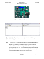
4.1.1 STK500 External Communication Protocol (USART)
The USART available on the STK500 is dependent on the MCU installed in one of the target
sockets [1], and it is used to communicate from the target MCU to various other devices [10]. In
this project, the target microcontroller is the ATmega8515L, which is installed in socket
SCKT3000D3 as shown in Figure 1.6. The USART interface of the STK500 consists of three
registers: the USART control and status register, the USART baud rate register, and the USART
data register (which is either 8-bit or 16-bit depending on the CPU of the target microcontroller)
[10]. The ATmega8515L is an 8-bit AVR (i.e. it has an 8-bit RISC CPU) so its USART data
register is an 8-bit register.
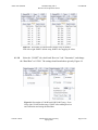
The keywords given to the USART registers by the CodeVisionAVR library for
ATmega8515L microcontrollers are UCSRA, UCSRB, UCSRC, UBRRH, and UBRRL where the
UCSRx keywords correspond to the high (A), middle (B), and low (C) sections of the USART
Control and Status Register and the UBRRx keywords correspond to the high (H) and low (L)
sections of the USART Baud Rate Register.
The USART data register is controlled by the specialized I/O functions provided in the
avr-libc library. Such input functions include getc and gets and such output functions include
putc, puts, and printf. These are the same functions available in the cstdio header of the
C Library (libc) [11], but they have been revised in the AVR C Library (avr-libc) for USART
communication with respect to AVR microcontrollers [10].
The required hardware setup to enable the use of the USART on the STK500 is given by
the instructions in section 2.2. Appendix section A.2.1 provides a sample program that can be
used to test USART communication between the board and its host. Sections 3.1 and 3.2 of this
Vincent A. Rosa
Florida Gulf Coast University
Spring 2009
Page 1 of 50
Atmel AVR STK500
Communicating with a
Host PC and Temperature Sensor
User Manual
document explain the necessary steps to take before applications development can begin on the
host PC. The following instructions describe steps to implement the application in Appendix
A.2.1 using the CodeVisionAVR IDE.
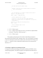
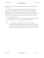
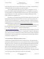
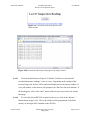
4.1.1.1
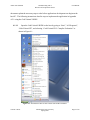
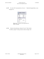
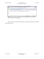
Open the CodeVisionAVR IDE on the host by going to “Start”, “All Programs”,
“CodeVisionAVR”, and selecting “CodeVisionAVR C Compiler Evaluation” as
shown in Figure 4.1.
Figure 4.1 Screenshot of how to start CodeVisionAVR Evaluation.
Vincent A. Rosa
Florida Gulf Coast University
Spring 2009
Page 2 of 50
Atmel AVR STK500
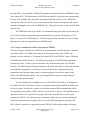
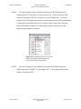
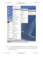
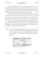
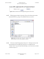
4.1.1.2
Communicating with a
Host PC and Temperature Sensor
User Manual
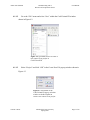
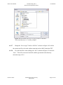
Go to the “File” menu and select “New” within the CodeVisionAVR window
shown in Figure 4.2.
Figure 4.2 Screenshot of how to create a
new source file or project in
CodeVisionAVR.
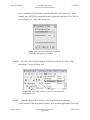
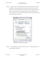
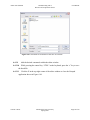
4.1.1.3
Select “Project” and click “OK” in the Create New File pop-up window shown in
Figure 4.3.
Figure 4.3 Screenshot of the
CodeVisionAVR pop-up selection
window to decide whether to
create a new source file or project.
Vincent A. Rosa
Florida Gulf Coast University
Spring 2009
Page 3 of 50
Atmel AVR STK500
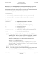
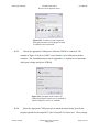
4.1.1.4
Communicating with a
Host PC and Temperature Sensor
User Manual
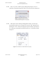
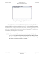
Select “Yes” in the “Confirm” pop-up window shown in Figure 4.4 to use a
wizard that will automatically generate certain AVR code based on the settings given.
Figure 4.4 Screenshot of the pop-up
window confirming whether or not to use
CodeWizardAVR to generate a new project.
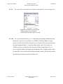
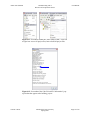
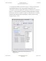
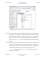
4.1.1.5
Under the tab “Chip” within the CodeWizardAVR window, select the target
microcontroller (in this case, the ATmega8515L) from the “Chip” drop-down menu
and change the “Clock” setting to the appropriate System Oscillator Clock frequency
(fOSC) with respect to the target microcontroller (in this case, 3.6864 MHz) as shown
in Figure 4.5.
Figure 4.5 Screenshot of CodeWizardAVR Chip setup.
Vincent A. Rosa
Florida Gulf Coast University
Spring 2009
Page 4 of 50
Atmel AVR STK500
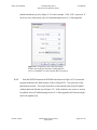
4.1.1.6
Communicating with a
Host PC and Temperature Sensor
User Manual
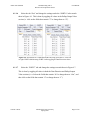
Select the tab “Port” and change the settings under the “PORTA” tab to match
those in Figure 4.6. This is done by toggling all values in the Pullup/Output Value
section (i.e. click on the fields that contain “T” to change them to “P”).
Figure 4.6 Screenshots of CodeWizardAVR Ports setup for PORTA. From left
to right: PORTA default setup; PORTA after toggling all Data Direction values.
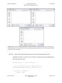
4.1.1.7
Select the “PORTC” tab and change the settings to match those in Figure 4.7.
This is done by toggling all values in both the Data Direction and Pullup/Output
Value sections (i.e. click on the fields that contain “In” to change them to “Out”, and
then click on the fields that contain “0” to change them to “1”).
Vincent A. Rosa
Florida Gulf Coast University
Spring 2009
Page 5 of 50
Atmel AVR STK500
Communicating with a
Host PC and Temperature Sensor
User Manual
Figure 4.7 Screenshot of CodeWizardAVR Ports setup for PORTC.
From left to right: PORTC default setup; PORTC after toggling all values.
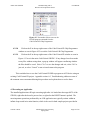
4.1.1.8
Select the “USART” tab, check both “Receiver” and “Transmitter”, and change
the “Baud Rate” to 115200. The settings should match those given by Figure 4.8.
Figure 4.8 Screenshot of CodeWizardAVR USART setup. From
left to right: USART default setup; USART after enabling Receiver
and Transmitter and setting the Baud Rate.
Vincent A. Rosa
Florida Gulf Coast University
Spring 2009
Page 6 of 50
Atmel AVR STK500
4.1.1.9
Communicating with a
Host PC and Temperature Sensor
User Manual
Go to the “File” menu and select “Generate, Save and Exit” as seen in Figure 4.9.
Figure 4.9 Screenshot of generating and
saving a program formed using the
CodeWizardAVR within CodeVisionAVR.
4.1.1.10
Go to your desired directory, say “C:\Documents and Settings\Administrator\My
Documents”, and create a new folder, say “STK500_TestProg” (Note: it is good
practice in CodeVisionAVR development to save all project files for a project within
the same designated folder). Go into this folder and give the C file a name, say
“stk500_test_prog” as shown by the first pop-up window within Figure 4.10. A
series of pop-up windows will appear for naming other files. Simply provide a name
for these files – they can be named with the same name as the C file, but they must be
given different extensions as shown in Figure 4.10.
Vincent A. Rosa
Florida Gulf Coast University
Spring 2009
Page 7 of 50
Atmel AVR STK500
Communicating with a
Host PC and Temperature Sensor
User Manual
Figure 4.10 From left to right, top to bottom: pop-up window to save the C source file (.c extension);
pop-up window to save the C project file (.prj extension); pop-up window to save the CodeVisionAVR
project file (.cwp extension).
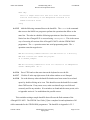
4.1.1.11
Add the following code to the same areas shown in the program given in
Appendix section A.2.1 (these areas are relatively located towards the beginning and
end of the provided code).
#include <delay.h> // Contains “delay_ms()”
// Send the following message via USART communication
printf("USART Communication Test: Succeeded!!!\r\n");
// Check state of PORTA Pins
if(PINA != 0xFF)
Vincent A. Rosa
Florida Gulf Coast University
Spring 2009
Page 8 of 50
Atmel AVR STK500
Communicating with a
Host PC and Temperature Sensor
User Manual
{
// If a button is pressed (input pulled low), toggle bits on PORTC
PORTC = ~PORTC;
// Send the following message via USART communication
printf("Hello!\r\n");
// Delay so flashing LED's are visible
delay_ms(1000);
printf("Goodbye!\r\n");
PORTC = ~PORTC;
}
4.1.1.12
Got to the “File” menu and select “Save All” as seen in Figure 4.11 to save all
changes made to any of the project files.
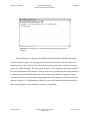
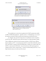
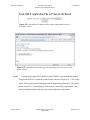
4.1.1.13
Go to the “Project” menu and select “Build All” as shown in Figure 4.11. Doing
this will build and compile all necessary files (including the HEX file used to
program the flash memory of the target MCU) from the code provided within the
target C file (in this case, from “stk500_test_prog.c”). It is possible for compilation
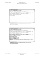
errors to occur during this process, but the results within the “Information” pop-up
window should look similar to those in Figure 4.12 if none appear. If any errors
exist, they will appear in the “Errors” message window shown in Figure 4.13. The
IDE will provide suggestions within this window on how to fix any incurred
compilation errors. Click “OK” within the Information pop-up window to proceed.
Vincent A. Rosa
Florida Gulf Coast University
Spring 2009
Page 9 of 50
Atmel AVR STK500
Communicating with a
Host PC and Temperature Sensor
User Manual
Figure 4.11 Screenshots within the CodeVisonAVR IDE. From left
to right: how to save all project files; how to build all project files.
Figure 4.12 Screenshot of the CodeVisionAVR “Information” popup window that appears after building project.
Vincent A. Rosa
Florida Gulf Coast University
Spring 2009
Page 10 of 50
Atmel AVR STK500
Communicating with a
Host PC and Temperature Sensor
User Manual
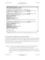
Figure 4.13 Screenshot of the CodeVisionAVR IDE with an emphasis on the Errors message
window.
4.1.1.14
Keep the CodeVisionAVR IDE open and go to the Uploading an Application
section 4.2.2 to program the target MCU with the application produced in this section.
This concludes writing a sample application that can be used to test USART
communication where data is sent from the STK500 to the host PC. The variables PINA and
PORTC shown in the code given in step 4.1.1.11 are the defined in the mega8515.h library
header file, which is automatically included when the code is generated from steps 4.1.1.9 and
4.1.1.10. These variables allow for control over the physical PORTA and PORTC headers. A
variable given by PINx accesses all pins of PORTx where x represents an appropriate port letter
from A through E. Individual pins of a port header can be accessed using the dot operator
Vincent A. Rosa
Florida Gulf Coast University
Spring 2009
Page 11 of 50
Atmel AVR STK500
Communicating with a
Host PC and Temperature Sensor
User Manual
followed by the appropriate pin number. For example, PINB.0 accesses pin 0 of PORTB, i.e.
PB0 on the board, and PIND.7 accesses PD7.
4.1.2 myTWI Communication Protocol (I2C)
The myTWI Temperature Sensor uses the TWI (I2C bus) to communicate with external devices
where I2C is a serial data bus developed by Philips Semiconductors in the 1980s and is now a
worldwide standard [5]. The I2C bus is intended for communication of relatively small amounts
of data across relatively short distances [5].
The serial data (SDA) and serial clock (SCL) lines shown in the pinout in Figure 4.14 are
the physical elements responsible for I2C data communication. The software used to parallel
these hardware constructs is given in Appendix section A.2.2.1 and is further explained in
section 4.1.3.
4.1.3 DAQ with the STK500 and myTWI
The instructions provided within this section establish a data acquisition system with an STK500
evaluation board, a myTWI Temperature Sensor, and a host PC. Performing the following steps
will reproduce the program given in Appendix section A.2.2.1. The specifics of the code are
explained by the comments given within the application.
4.1.3.1
Perform steps 4.1.1.1 through 4.1.1.8
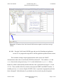
4.1.3.2
Select the “I2C” tab, select “PORTE” from the “I2C Port” drop-down menu, and
then check “Enabled” under the “LM75” tab. The settings should now match those
shown in Figure 4.14 (if they do not match, change them so they do). Notice how the
“SDA Bit” is set to “0” and the “SCL Bit” is set to “1”. This parallels the hardware
setup established in the Hardware Connectivity section 2.3.2.
Vincent A. Rosa
Florida Gulf Coast University
Spring 2009
Page 12 of 50
Atmel AVR STK500
Communicating with a
Host PC and Temperature Sensor
User Manual
Figure 4.14 Screenshot of the CodeWizardZVR
I2C setup. The I2C Port is set to PORTE and
LM75 is set as Enabled.
4.1.3.3
Perform steps 4.1.1.9 through 4.1.1.13 with the following revisions:
•
4.1.1.9 – Perform as given.
•
4.1.1.10 – The same directory can be used (“C:\Documents and
Settings\Administrator\My Documents”), but create a different folder, say
“STK500_DAQ_Temp”. Also, use a different name to save the files given by the
series of pop-up windows, say “stk500_daq_temp”.
•
4.1.1.11 – Add the following code from Appendix section A.2.2.1 instead of the code
originally given at this step (the areas the following code is added are relatively
located at the beginning and end of the program given in section A.2.2.1 of the
appendix):
// Standard Input/Output functions
#include <stdio.h> // Contains "printf()" and sprintf()"
#include <delay.h> // Contains "delay_ms()"
#include <stdlib.h> // Contains "abs()"
/*
* The "int lm75_temperature_10(unsigned char chip)" function
* returns the temperature in degrees C times 10 retrieved from
Vincent A. Rosa
Florida Gulf Coast University
Spring 2009
Page 13 of 50
Atmel AVR STK500
Communicating with a
Host PC and Temperature Sensor
User Manual
* the LM75 sensor with the address "chip".
*
* CAUTION: A 300ms delay must be present between two successive
*
calls to this function.
*/
// Get the temperature as an integer in degrees Celcius times 10
tempC_x10 = lm75_temperature_10(0);
PORTC = ~PORTC; // toggle LED values
// Send the temperature data via USART
// Divide by 10 to get the proper whole number temperature
// Append the the decimal value of the temperature to one place by
// using modulus 10
printf("%-i.%-u",tempC_x10/10,abs(tempC_x10%10));
PORTC = ~PORTC;
// Delay for DELAY_ms amount of time
delay_ms(DELAY_ms);
•
4.1.1.12 – Perform as given.
•
4.1.1.13 – Perform as given (in this case, however, all of the files compiled and built
are from the C file given by “stk500_daq_temp.c”).
•
4.1.1.14 – Perform as given.
This concludes creating the software that correlates with the DAQ system formed
between the STK500 PCB and myTWI Temperature Sensor. The CodeVisionAVR User Manual
[13] has more information on the functions available in the CodeVisionAVR LM75 library given
by the lm75.h header file, which is automatically included when the code is generated from
instruction 4.1.3.3.
4.2 Uploading an Application (Programming the Board)
It is important to remember that the target microcontroller installed on the STK500 is what is
actually being programmed. Only HEX file programs can be uploaded to the flash memory of
Vincent A. Rosa
Florida Gulf Coast University
Spring 2009
Page 14 of 50
Atmel AVR STK500
Communicating with a
Host PC and Temperature Sensor
User Manual
the target MCU, and only HEX or ROM file programs can be uploaded to the EEPROM memory
of the target MCU. The flash memory of AVR microcontrollers is typically what is programmed
because of its available space and relatively unlimited read and write life cycles. EEPROM
memory has a limited write life cycle so only programs that will be used frequently and remain
relatively unchanged are reserved for EEPROM [10]. This project focuses on the use of the flash
memory only.
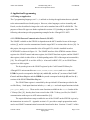
The STK500 PCB has a specific RS-232 communication protocol that requires data to be
received for in-system programming using eight data bits, one stop bit, and no parity at 115.2
kbps (i.e. at a rate of 115200 baud) [14]. The following subsections describe two ways of using
this protocol to upload an application to an STK500 board.
4.2.1 Using a Command Line Utility to Program the STK500
The microcontroller installed on an STK500 can be programmed using the Windows command
line utility (CMD). The CMD session must be in the same directory as the “Stk500.exe”
program, which is located in “C:\Program Files\Atmel\AVR Tools\STK500” when AVR Studio
is installed in its default directory. The Stk500.exe program is an STK500 DOS programmer
provided by Atmel. It can be copied and pasted to any desired location after AVR Studio is
installed. The HEX file that will be programmed to the board must either be in the same location
as the Stk500.exe program or its directory must be provided in the command line used to
program the board (the preceding option is recommended and is used for the sample DAQ
project provided in this document). Any pre-existing HEX file can have its name changed
without it losing its functionality.
A list of all applicable commands is given in the STK500 User Guide [1]. Being able to
use CMD allows for a batch file (.bat) to be created that automatically programs the board when
the file is opened. A batch file is simply a text file that contains CMD commands that will be
executed line-by-line within a CMD session as soon as the file is opened. The batch file given in
Appendix section A.2.2.3 provides an example of how the command utility can be used to
program the STK500. The following list of commands and how they are used accompany the
instructions that provided an example of how to use the CMD to program an ATmega8515L
MCU when it is installed in a target socket on an STK500. Before performing the following
Vincent A. Rosa
Florida Gulf Coast University
Spring 2009
Page 15 of 50
Atmel AVR STK500
Communicating with a
Host PC and Temperature Sensor
User Manual
instructions, be sure to establish the hardware setup described in the Hardware Connectivity
section 2.1 and then power on the board using the switch shown in Figure 2.3. The
Troubleshooting section of the appendix (section A.3) provides some common techniques used
to be sure the board is properly powered on and is ready to be used.
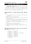
Commands Summary:
[-d device_name] [-m programming_mode] [-e optional_memory_device]
[-p memory_device] [-v memory_device] [-if HEX_file] [-c com_port]
Executed Commands:
-dATmega8515
==> get the protocols to program the Atmega8515
-ms
==> serial programming mode
-e
==> erase all memory devices before programming
-pf
==> program the flash memory
-vf
==> verify the flash memory
-ifstk500_prog.hex
==> use the HEX file "stk500_prog.hex" to program the flash
-ccom4
==> use com4 as the communication port
4.2.1.1
Copy and paste both the “Stk500.exe” program and the desired HEX file into a
designated location, which is “C:\stk500_example” for this procedure. Create this
directory if it does not exist. CodeVisionAVR stores the HEX file built from an
application in a folder labeled “Exe” within the directory assigned for this
application. Use the HEX file located in
“C:\stk500_example\STK500_TestProg\Exe” created from section 4.1.1 to better
follow this example. Copy and paste this file into “C:\stk500_example” and rename
the pasted file to “stk500_prog.hex”.
4.2.1.2
Go to “Start” and select “Run” as shown in Figure 4.15
4.2.1.3
Type “cmd” into the text field of the Run utility that pops up as shown in Figure
4.16 and click “OK”. This will start a new instance of a CMD shell session.
Vincent A. Rosa
Florida Gulf Coast University
Spring 2009
Page 16 of 50
Atmel AVR STK500
4.2.1.4
Communicating with a
Host PC and Temperature Sensor
User Manual
Change the directory using the “cd” command followed by the location
designated in step 4.2.1 (e.g. enter cd C:\stk500_example as shown in Figure
4.17).
4.2.1.5
Enter the following line into the current CMD session:
stk500 -dATmega8515 -ms -e -pf -vf -ifstk500_prog.hex -ccom4
Figure 4.15 Screenshot of accessing the
Windows Run utility from the Start menu.
Vincent A. Rosa
Figure 4.16 Screenshot of the Windows Run
utility.
Florida Gulf Coast University
Spring 2009
Page 17 of 50
Atmel AVR STK500
Communicating with a
Host PC and Temperature Sensor
User Manual
Figure 4.17 Screenshot of a CMD session where the directory has been
changed.
This concludes how to program the STK500 using the Windows command line utility.
The error shown in Figure 4.18 will appear if the board is not powered on or has an incorrect
hardware setup. If this is the case, be sure the board is powered on and is set up as directed in
section 2.1 of this document. The error shown in Figure 4.19 will appear if the referenced HEX
file is not within the specified location. Simply correct this by referencing the correct location or
by adding the referenced HEX file into the same location as the Stk500.exe program. Figure
4.20 shows the board was successfully programmed after fixing the two previously listed errors.
Appendix section A.3, Troubleshooting, addresses some of the common errors encountered in
this section and provide some techniques on how to resolve them.
Vincent A. Rosa
Florida Gulf Coast University
Spring 2009
Page 18 of 50
Atmel AVR STK500
Communicating with a
Host PC and Temperature Sensor
User Manual
Figure 4.18 Screenshot of a CMD session where an error occurred
programming an STK500.
Figure 4.19 Screenshot of a CMD session where an error occurred
programming an STK500.
Vincent A. Rosa
Florida Gulf Coast University
Spring 2009
Page 19 of 50
Atmel AVR STK500
Communicating with a
Host PC and Temperature Sensor
User Manual
Figure 4.20 Screenshot of a CMD session where programming an STK500 was successful.
4.2.2 Using CodeVisionAVR Evaluation to Program the STK500
The following procedure instructs the user how to program one of the AVR devices installed in a
target socket on the STK500 PCB. The AVR device being programmed within this procedure is
the ATmega8515L MCU. If CodeVisionAVR is not already opened, refer to instruction 4.1.1.1
to open the CodeVisionAVR Evaluation IDE.
4.2.2.1
If a project is not already opened within the CodeVisionAVR IDE, go to the
“File” menu, select “Open”, go to the desired directory that contains a
CodeVisionAVR project file (.prj), and open this project as in Figure 4.21. Be sure
that all project files have already been built as in instruction 4.1.1.12. Otherwise, skip
this step.
Vincent A. Rosa
Florida Gulf Coast University
Spring 2009
Page 20 of 50
Atmel AVR STK500
Communicating with a
Host PC and Temperature Sensor
User Manual
Figure 4.21 Screenshot of how to open an existing CodeVisionAVR project from the
CodeVisionAVR IDE.
4.2.2.2
Go to the “Settings” menu and select “Programmer” as seen in Figure 4.22 to
establish the appropriate AVR board with which the CodeVisionAVR Chip
Programmer will be communicating.
Figure 4.23 Screenshot of how to access the
CodeVisionAVR Programmer settings.
4.2.2.3
Select the desired AVR board under the “AVR Chip Programmer Type” dropdown menu within the “Programmer Settings” pop-up window. Also select the COM
Vincent A. Rosa
Florida Gulf Coast University
Spring 2009
Page 21 of 50
Atmel AVR STK500
Communicating with a
Host PC and Temperature Sensor
User Manual
port to which the serial/USB cable is attached from the AVR board in use. In this
example, an AVR STK500 evaluation board is connected to the host PC at COM3 as
seen in Figure 4.23. Click “OK” to proceed.
Figure 4.23 Screenshot of the CodeVisionAVR
Programmer Settings pop-up window.
4.2.2.4
Go to the “Tools” menu within the CodeVisionAVR IDE and select “Chip
Programmer” as seen in Figure 4.24.
Figure 4.24 Screenshot of how to access the CodeVisionAVR
Programmer tool.
4.2.2.5
Select the desired MCU from the “Chip” drop-down menu within the
CodeVisionAVR Chip Programmer window. Also select the appropriate “SCK Freq”
Vincent A. Rosa
Florida Gulf Coast University
Spring 2009
Page 22 of 50
Atmel AVR STK500
Communicating with a
Host PC and Temperature Sensor
User Manual
(i.e. the appropriate SPI Bus “Serial Clock Frequency”, which is the speed for the
Serial Peripheral Interface, SPI). In this example, the target MCU is the
ATmega8515L, which has a default SCK frequency of 230400 Hz [15] as shown in
Figure 4.25. The ATmega8515(L) Datasheet [4] further explains how to calculate
this frequency with respect to different settings (e.g. SCK with respect to Oscillator
Frequency in the subsection “SPI Control Register – SPCR” of section “Serial
Peripheral Interface – SPI”).
Figure 4.25 Screenshot of the CodeVisionAVR Chip
Programmer tool.
Vincent A. Rosa
Florida Gulf Coast University
Spring 2009
Page 23 of 50
Atmel AVR STK500
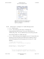
4.2.2.6
Communicating with a
Host PC and Temperature Sensor
User Manual
Go to the “Program” menu within the CodeVisionAVR Chip Programmer
window and select “Erase Chip” as seen in Figure 4.26. This will erase the flash
memory of the target AVR device (in this case, the ATmega8515L). It is good
practice in AVR development to always erase the target memory before programming
it. Sometimes erasing the memory is a required action to ensure data consistency
between the amount of utilized (i.e. programmed) memory and the size of the
program being uploaded to memory.
Figure 4.26 Screenshot of how to access the
Erase Chip program command from the
CodeVisionAVR Chip Programmer.
4.2.2.7
Go to the “Program” menu within the CodeVisionAVR Chip Programmer
window and select “FLASH” as seen in Figure 4.27. This will program the flash
memory of the target MCU.
Vincent A. Rosa
Florida Gulf Coast University
Spring 2009
Page 24 of 50
Atmel AVR STK500
Communicating with a
Host PC and Temperature Sensor
User Manual
Figure 4.27 Screenshot of how to access the
FLASH program command from the
CodeVisionAVR Chip Programmer
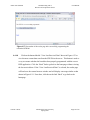
4.2.2.8
Click on the X in the top-right corner of the CodeVisionAVR Chip Programmer
window as seen in Figure 4.25 to exit the CodeVisionAVR Chip Programmer.
4.2.2.9
Click on the X in the top-right corner of the CodeVisionAVR window as seen in
Figure 4.13 to exit the entire CodeVisionAVR IDE. If any changes have been made
to any files without saving them, a pop-up window will appear confirming whether
the files should be saved. Select “Yes” to save the changes and exit, select “No” to
just exit, or select “Cancel” to not exit and return to the program.
This concludes how to use the CodeVisionAVR IDE to program an AVR device using an
existing CodeVisionAVR project. Appendix section A.3, Troubleshooting, addresses some of
the common errors encountered during this procedure and explains how to resolve them.
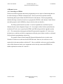
4.3 Executing an Application
The installed application will begin executing right after it is loaded into the target MCU of the
STK500, right after the board is powered on, or right after the RESET button is pushed. The
most important operations performed by an AVR application are typically written within an
infinite loop nested in its main function, which is the case for both sample projects provided in
Vincent A. Rosa
Florida Gulf Coast University
Spring 2009
Page 25 of 50
Atmel AVR STK500
Communicating with a
Host PC and Temperature Sensor
User Manual
Appendix section A.2. Therefore, these operations should run continuously while the board is
powered on.
It is imperative to remember that the functionality of the board with respect to its
application software is dependent on the hardware setup (e.g. if PORTA is programmed to
control the switches, then a 10-wire cable must properly connect the PORTA header to the
SWITCHES header). Appendix section A.3, Troubleshooting, addresses how to resolve some of
the common issues encountered that would cause the board to not respond as desired with
respect to the installed application.
The following set of instructions provides how to check whether the sample programs in
Appendix sections A.2.1 and A.2.2.1 are running properly on the STK500 PCB.
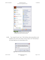
4.3.1
Open the HyperTerminal program by going to “Start”, “All Programs”,
“Accessories”, “Communications”, and selecting “HyperTerminal” as seen in Figure
4.28. If this is the first time HyperTerminal is used, enter an area code and follow the
on-screen instructions given by the HyperTerminal program. Click “OK” to proceed.
Vincent A. Rosa
Florida Gulf Coast University
Spring 2009
Page 26 of 50
Atmel AVR STK500
Communicating with a
Host PC and Temperature Sensor
User Manual
Figure 4.28 Screenshot of how to start a HyperTerminal session.
4.3.2
Type a Name for the HyperTerminal session, say “com3_STK500_DAQ”, and
select an Icon within the “Connection Description” window as shown in Figure 4.29.
Click “OK” to proceed.
Vincent A. Rosa
Florida Gulf Coast University
Spring 2009
Page 27 of 50
Atmel AVR STK500
Communicating with a
Host PC and Temperature Sensor
User Manual
Figure 4.29 Screenshot of the Connection
Description window used by HyperTerminal
to establish a new connection.
4.3.3
Choose the appropriate COM port to which the STK500 is connected. The
example in Figure 4.30 shows COM3 is used, but this can be different on another
computer. The Troubleshooting section in Appendix A.3 explains how to determine
which port is being used by the STK500.
Figure 4.30 Screenshot of the Connect To
window that HyperTerminal uses to establish at
which COM port to receive or send data.
4.3.4
Select the appropriate COM properties to match the requirements given by the
program uploaded to the target MCU (the ATmega8515L in this case). These settings
Vincent A. Rosa
Florida Gulf Coast University
Spring 2009
Page 28 of 50
Atmel AVR STK500
Communicating with a
Host PC and Temperature Sensor
User Manual
should match those given by Figure 4.31 for this example. Click “OK” to proceed. If
an error occurs at this point, refer to Troubleshooting section A.3 of the appendix.
Figure 4.31 Screenshot of the COM port settings
window used by HyperTerminal to establish how to
receive or send data via serial using the RS-232 protocol.
4.3.5
Push the RESET button on the STK500 board shown in Figure 4.32 to restart the
program installed in the flash memory of the ATmega8515L. Now push one of the
push-button switches. The results from these actions should yield a HyperTerminal
window that looks like the one in Figure 4.33. If the results are not correct or seem to
be garbled, refer to Troubleshooting section A.3 of the appendix; the firmware might
need to be updated [16].
Vincent A. Rosa
Florida Gulf Coast University
Spring 2009
Page 29 of 50
Atmel AVR STK500
Communicating with a
Host PC and Temperature Sensor
User Manual
Figure 4.32 Picture emphasizing the RESET
button on the STK500 evaluation board.
Figure 4.33 From left to right: a screenshot of a HyperTerminal session with respect to the test
application for USART communication; a screenshot of a HyperTerminal session with respect to the
myTWI-to-STK500 DAQ application.
4.3.6
Click on the X in the top-right corner of the HyperTerminal window as shown in
the Figure 4.33 screenshots to exit the HyperTerminal program. Two pop-up
windows will follow: the first shown in Figure 4.34 confirms whether you want to
exit HyperTerminal (click “Yes” to proceed with exiting), and the second shown in
Figure 4.35 asks whether you want to save the current HyperTerminal session (click
“Yes” to save the session and then exit or click “No” to just exit).
Vincent A. Rosa
Florida Gulf Coast University
Spring 2009
Page 30 of 50
Atmel AVR STK500
Communicating with a
Host PC and Temperature Sensor
User Manual
Figure 4.34 Screenshot of the HyperTerminal
pop-up window that appears when an attempt has
been made to exit a HyperTerminal session.
Figure 4.35 Screenshot of the HyperTerminal pop-up
window that appears when an exiting an unsaved
HyperTerminal session.
This concludes how to execute the test application for USART communication and the
myTWI-to-STK500 DAQ application. Appendix section A.3, Troubleshooting, covers some of
the common errors that arise while carrying out the instructions provided in this section.
Try editing the code used in this section to have one push-button switch correspond to
one LED (say SW3 with LED3) where the LED will turn on or off when this button is pushed.
Then try adding some code that will send a message to the host via USART when a different
button is pushed, say SW7. It is important to know that PA3 controls SW3 and that PA7 controls
SW7 since PORTA is connected to the SWITCHES header. Similarly, PC3 controls LED3 since
PORTC is connected to the LEDS header. Also note from the provided sample programs in
Appendix section A.2 that a carriage return (“\r”) must be sent when starting a new line (“\n”) in
HyperTerminal; otherwise, the data sent will be skewed.
Vincent A. Rosa
Florida Gulf Coast University
Spring 2009
Page 31 of 50
Atmel AVR STK500
Communicating with a
Host PC and Temperature Sensor
User Manual
4.4 Remote Access
4.4.1 Networking an STK500
Web accessed data acquisition and remote programming are two aspects of networking that can
be achieved using an STK500 evaluation board. Web accessed data acquisition includes
broadcasting data acquired from the STK500 board via the Internet. Remote programming
includes allowing a remotely located user to program the STK500 via the Internet. Both of these
networking aspects can be fulfilled by using a website as the user interface.
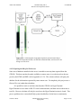
The DAQ system formed in section 4.1.3 can be expanded into a web-based system
illustrated by the context diagram in Figure 4.36. An example website for this system that runs
on the host PC/web server is given by the HTML and PHP code provided in Appendix section
A.2.2. The customized serial program and batch file presented in Appendix A.2.2 also run on
the host/server, and they are the key components used by the given website to achieve web-based
DAQ and remote programming, respectively.
The sample website is hosted using IIS (Internet Information Services) on the same
Windows PC that serves as the host for the STK500 board. However, the web server is not
required to be the same machine as the host PC. How to establish a web server goes beyond the
scope of this document, but the core components used to develop a networked STK500 are
further explained in sections 4.4.2 and 4.4.3.
Vincent A. Rosa
Florida Gulf Coast University
Spring 2009
Page 32 of 50
Atmel AVR STK500
Communicating with a
Host PC and Temperature Sensor
User Manual
Figure 4.36 Context diagram of the data acquisition system formed with a
myTWI Temperature Sensor, an STK500 evaluation board, and a host PC also
acting as a web server.
4.4.2 Preparing the Host for Web Access
Some sort of database installed on the server is needed to store any data acquired from the
STK500. This data can then be made available to remote users via a website such as the one
given by the HTML and PHP code in Appendix A.2.2.4. The website software will query the
database for the information requested by some remote user. For simplicity, this project uses a
flat text file (.txt) rather than a database.
It is possible to retrieve and store data from the STK500 via HyperTerminal.
HyperTerminal receives data via RS-232 serial communication, and then can save them into a
text file. However, the data will only be saved once the HyperTerminal session is closed. This
poses a problem since a networked DAQ system should allow for the host to continuously
Vincent A. Rosa
Florida Gulf Coast University
Spring 2009
Page 33 of 50
Atmel AVR STK500
Communicating with a
Host PC and Temperature Sensor
User Manual
acquire data while the target system (the STK500 in this case) is running. A customized serial
communication utility can be developed to overcome this problem.
The serial communication program “host_serial_com.cpp” in Appendix A.2.2.2 was
produced for a Windows platform using the Win32 API [12]. It is designed to run on the host
PC to store all data received from the STK500 board into a text file. This text file can then be
used to broadcast the received data via the Internet on a webpage as implemented with the
HTML and PHP code in Appendix A.2.2.4.
Developing a serial communication program for a Windows platform can be achieved by
following the instructions provided in the Windows Serial Port Programming document [12].
The Win32 API can be imported into a C++ program by including the “windows.h” header file
when using the Microsoft Visual Studio IDE. Microsoft provides free versions of Visual Studio
called Express Editions (available online at http://www.microsoft.com/Express/).
It is important to know that the current Win32 API has been changed by Microsoft to use
the UNICODE character set instead of the ASCII character set still utilized by the standard
C/C++ libraries. These standard C/C++ libraries are outlined online at
<http://www.cplusplus.com/reference/>. Another important tip is that the Windows sockets API
given by “winsock2.h” must be included into a C++ program before “windows.h” when both are
used. This prevents duplicate definitions for variables with the same names that are contained in
both header files. Both of the tips given here are implemented and commented upon within the
serial program in Appendix A.2.2.2.
4.4.3 Programming the STK500 from a Remote Location
An application to program the STK500 needs to be located on its host. This application must
also be made available for the web server to execute when some remote user chooses to program
the board via a website. A batch file can be used as the application that programs the board and
a PHP function can be used to execute this batch file when a remote user makes a request (e.g.
pushes a button) to program the board from the website. Before the board is programmed,
however, the user must upload an appropriate HEX or ROM application to the server. The
server must then send the uploaded application to the host of the STK500. Since the host and the
server are the same machine for this project, the latter step can be omitted.
Vincent A. Rosa
Florida Gulf Coast University
Spring 2009
Page 34 of 50
Atmel AVR STK500
Communicating with a
Host PC and Temperature Sensor
User Manual
The PHP code in Appendix section A.2.2.4 provides an example on how to achieve
uploading files to the server and how to execute a program installed on the server. It is important
to use proper directories and file names. For this project, the batch file is placed in the same
directory as the PHP program that executes it and each uploaded HEX file has its name changed
to match the one used within this batch file (“stk500_prog.hex” in this case).
The purpose of the batch file “stk500_program_flash.bat” in Appendix A.2.2.3 is to allow
a remotely located user to program the flash memory of the installed target MCU via the Internet
from a webpage. This is achieved by the webpage allowing for the user to first upload a HEX
file to the server/host PC and then initiate an event (i.e. push a button) to execute the batch file
on the server/host. Executing the batch file should then program the flash of the target MCU.
A batch file is a special type of text file that contains lines of commands that are executed
within a CMD window session as soon as the file is opened. The following instructions can be
used to make a batch file in Windows XP. Although Notepad is used in the following steps as
the text editor, any text editor can be used (e.g. WordPad).
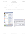
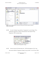
4.4.3.1
The Folder Options for Windows Explorer must be set up so that text files (.txt)
can be saved as batch files (.bat). Open an Explorer window by opening any folder
(e.g. “My Computer” or “My Documents”). Then click on the “Tools” menu and
select “Folder Options…” as seen in Figure 4.37. The “Folder Options” window
should pop up.
Figure 4.37 Screenshot of accessing the Windows
Folder Options from Windows Explorer.
Vincent A. Rosa
Florida Gulf Coast University
Spring 2009
Page 35 of 50
Atmel AVR STK500
4.4.3.2
Communicating with a
Host PC and Temperature Sensor
User Manual
Select the “View” tab within the Folder Options window and make sure that the
field labeled as “Hide extensions for known file types” is unchecked as shown in
Figure 4.38. Click on the check box to uncheck this field if is not already unchecked.
Select “Apply” and then “OK” to apply the settings and exit the Folder Options
window, respectively. These settings will remain even after the machine is shutdown
so this only needs to be done once.
Figure 4.38 Screenshot of the View section within the
Folder Options configuration for Windows.
4.4.3.3
Go to the Windows “Start” menu, and select “Run…” as shown in Figure 4.39 to
open the Windows Run utility.
Vincent A. Rosa
Florida Gulf Coast University
Spring 2009
Page 36 of 50
Atmel AVR STK500
Communicating with a
Host PC and Temperature Sensor
User Manual
Figure 4.39 Screenshot of how to access the
Windows Run utility from the Start menu.
4.4.3.4
Type “notepad” into the “Open:” field of the Run window and push Enter on the
keyboard or select “OK” in the window as shown in Figure 4.40. This should open
the Notepad application for writing/editing text files.
Figure 4.40 Screenshot of the Windows Run utility.
Vincent A. Rosa
Florida Gulf Coast University
Spring 2009
Page 37 of 50
Atmel AVR STK500
4.4.3.5
Communicating with a
Host PC and Temperature Sensor
User Manual
Go to the “File” menu and select “Save As…” within the Notepad editor as seen
in Figure 4.41.
Figure 4.41 Screenshot of accessing the Save As
feature in Notepad.
4.4.3.6
Select the desired directory from the “Save in” field, which is
“C:\stk500_example” for this procedure as shown in Figure 4.42.
Vincent A. Rosa
Florida Gulf Coast University
Spring 2009
Page 38 of 50
Atmel AVR STK500
Communicating with a
Host PC and Temperature Sensor
User Manual
Figure 4.42 Screenshot of the Save As pop-up window in Windows.
The selected directory is <C:\stk500_example>.
4.4.3.7
Change the “Save as type” field to “All Files” as shown in Figure 4.43 to allow
the current text file to be saved with an extension (such as BAT) other than TXT.
4.4.3.8
Give the batch file a name ending with “.bat” as shown in Figure 4.43 and click
“Save”. This will create a new batch file with the given name in the directory
selected in step 4.4.3.6.
Vincent A. Rosa
Florida Gulf Coast University
Spring 2009
Page 39 of 50
Atmel AVR STK500
Communicating with a
Host PC and Temperature Sensor
User Manual
Figure 4.43 Screenshot of an instance of the Save As window.
4.4.3.9
Add the desired commands within the editor window.
4.4.3.10
While pressing the control key “CTRL” on the keyboard, press the “s” key to save
the batch file.
4.4.3.11
Click the X in the top-right corner of the editor window to close the Notepad
application shown in Figure 4.44.
Vincent A. Rosa
Florida Gulf Coast University
Spring 2009
Page 40 of 50
Atmel AVR STK500
Communicating with a
Host PC and Temperature Sensor
User Manual
Figure 4.44 Screenshot of the Notepad editor opened to
the empty file “stk500_program_flash.bat”.
This concludes how to create a batch file. The requirements for writing a batch file to
program an STK500 parallel those established in section 4.2.1, which explains how to program
an STK500 using the Windows command line utility (CMD). The following instructions can be
used to write a sample batch file that will erase the contents of the target MCU installed on the
STK500 board (the ATmega8515L in this example).
4.4.3.12
Create a new batch file or open the one created from steps 4.4.3.1 through
4.4.3.11. Go to the directory that contains the desired batch file, right click over the
file, and select “Edit” as seen in Figure 4.45. This will open a batch file for editing
(not running) in the default text editor (e.g. Notepad).
Vincent A. Rosa
Florida Gulf Coast University
Spring 2009
Page 41 of 50
Atmel AVR STK500
Communicating with a
Host PC and Temperature Sensor
User Manual
Figure 4.45 Screenshot of how to open a batch file to edit and not to run.
4.4.3.13
Every command in a batch file should be on its own line. It is common practice
to not display (i.e. to not echo) the commands contained within a batch file during
their execution in a CMD session. Add the command @ECHO OFF to the top of the
batch file to achieve this. The @ symbol prevents the command that follows from
being echoed. The ECHO OFF command stops all following commands from being
displayed.
4.4.3.14
It is good practice to provide comments to explain the purpose of the batch file
and why certain commands are used. All comments should not be executed so the
remark keyword REM must precede each individual comment line. Multiple lines of
comments can be handled in one block by placing them between the GOTO
label_name command and a label (e.g. :LABEL). Add the following block of
comments to the batch file.
Vincent A. Rosa
Florida Gulf Coast University
Spring 2009
Page 42 of 50
Atmel AVR STK500
Communicating with a
Host PC and Temperature Sensor
User Manual
GOTO skip
This is a sample batch file that will erase all contents
from the flash memory of the ATmega8515L installed on an
STK500 evaluation board.
:skip
4.4.3.15
Add the following command lines to the batch file. The stk500 is the command
that accesses the Stk500.exe program to perform the operations that follow on the
same line. The order in which the following operations are listed does not matter.
Notice how the ATmega8515L is accessed using -dATmega8515. This is the correct
way of accessing all versions of the ATmega8515 MCU with the STK500 DOS
programmer. The -ms operation enters into serial programming mode. The -e
operation erases the target device.
REM The following command redirects the CMD session to a directory
REM that contains the Stk500.exe program.
cd C:\stk500_example\
REM The following command will erase all contents in an ATmega8515L
stk500 -dATmega8515 -ms -e
4.4.3.16
Press CTRL and s at the same time on the keyboard to save the file.
4.4.3.17
Click the X at the top-right corner of the editor window to exit Notepad.
4.4.3.18
Go to the directory where the batch file that has now been created is saved and
open it by double-clicking on its icon. This should execute the batch file in a standalone CMD session. If any errors occur, make sure that all steps were followed
accurately and fix any mistakes. If no mistakes are found and the errors persist, refer
to Appendix section A.3 to troubleshoot the possible causes.
This concludes writing a sample batch file that will erase the flash contents of the
ATmega8515L MCU. The STK500 User Guide [1] has a complete list and explanation of all
viable commands for the STK500 DOS programmer. The batch file in Appendix A.2.2.3
Vincent A. Rosa
Florida Gulf Coast University
Spring 2009
Page 43 of 50
Atmel AVR STK500
Communicating with a
Host PC and Temperature Sensor
User Manual
provides a more complete example with comments on how to better utilize batch files to program
an STK500.
4.4.4 Website Operation
The following instructions explain how to operate the sample website given by the code
presented in Appendix section A.2.2.4. Steps 4.4.4.2 and 4.4.4.3 explain how to view the data
acquired from the myTWI-to-STK500 data acquisition system formed in section 4.1.3 of this
document. Steps 4.4.4.4 through 4.4.4.8 explain how to program the STK500 in this same DAQ
system. Internet Explorer is the web browser used to provide screenshots for this set of
instructions.
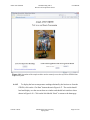
4.4.4.1
Go to <http://69.88.163.18/vincent/index.html> in a web browser (e.g. Internet
Explorer or Firefox). This is the web address to the sample website that allows for
data acquisition and remote programming, both with respect to the STK500
evaluation board that has an ATmega8515L MCU installed in one of its target
sockets. Figure 4.46 shows a screenshot of the homepage.
Vincent A. Rosa
Florida Gulf Coast University
Spring 2009
Page 44 of 50
Atmel AVR STK500
Communicating with a
Host PC and Temperature Sensor
User Manual
Figure 4.46 Screenshot of the sample website used to remotely access the myTWI-to-STK500 data
acquisition system.
4.4.4.2
To display the last ten temperature readings obtained by the host/server from the
STK500, click on the “Get Data” button shown in Figure 4.47. The results should
load and display over the current browser window and should look similar to those
shown in Figure 4.48. Click on the link labeled “Back” to return to the homepage.
Vincent A. Rosa
Florida Gulf Coast University
Spring 2009
Page 45 of 50
Atmel AVR STK500
Communicating with a
Host PC and Temperature Sensor
User Manual
Figure 4.47 Screenshot of the DAQ portion of the
sample website.
Figure 4.48 Screenshot of the DAQ results page for the sample website.
4.4.4.3
Click on the link shown in Figure 4.47 labeled “Click here to download all
recorded temperature readings ” to do as it says. Depending on the settings of the
browser being used, the file will be loaded and displayed over the current window, in
a new tab/window, or the browser will prompt to save the file to the local machine. If
the first happens, click on the “back” button of the browser to go back to the website
homepage.
4.4.4.4
To select the desired HEX file to upload to the server, click on the “Browse…”
button shown in figure 4.49. This is the file that will be programmed to the flash
memory of the target MCU installed on the STK500.
Vincent A. Rosa
Florida Gulf Coast University
Spring 2009
Page 46 of 50
Atmel AVR STK500
Communicating with a
Host PC and Temperature Sensor
User Manual
Figure 4.49 Screenshot of the remote programming portion of the website.
4.4.4.5
Within the pop-up window for choosing a file, go to the directory that contains
the desired HEX file (e.g. Figure 4.50) and double-click on it to select it.
Figure 4.50 Screenshot of the “Choose file” window used by
Internet Explorer to select a file to upload to a website.
4.4.4.6
Click on the “Upload” button shown in Figure 4.51. This figure also shows that
the local path of the selected HEX file from step 4.4.4.5 is displayed in the
“Filename” field. The results should load and display over the same browser window
as shown in Figure 4.52.
Vincent A. Rosa
Florida Gulf Coast University
Spring 2009
Page 47 of 50
Atmel AVR STK500
Communicating with a
Host PC and Temperature Sensor
User Manual
Figure 4.51 Screenshot of an instance of the remote programming section of
the sample website.
Figure 4.52 Screenshot of the results page after uploading a file to the server via the
sample website.
4.4.4.7
To program the target MCU installed on the STK500, click on the button labeled
“Program the STK500” within the results window shown in Figure 4.52. Click on the
“Back” link to go back to the homepage without programming the board. The results
shown in Figure 4.53 should display if the board is successfully programmed. This
also means that the application started execution right after being loaded.
Vincent A. Rosa
Florida Gulf Coast University
Spring 2009
Page 48 of 50
Atmel AVR STK500
Communicating with a
Host PC and Temperature Sensor
User Manual
Figure 4.53 Screenshot of the results page after successfully programming the
networked STK500.
4.4.4.8
Click on the button labeled “View Last Received Data” shown in Figure 4.53 to
view the most current data sent from the STK500 to the server. This button is used as
a way to reassure whether the board has been properly programmed with the correct
HEX application. Click the “Back” link to go back to the homepage without viewing
the last received data. If the “View Last Received Data” is selected, the results page
will load over the current browser window and will display a message similar to that
shown in Figure 4.54. From here, click the on the link “Back” to go back to the
homepage.
Vincent A. Rosa
Florida Gulf Coast University
Spring 2009
Page 49 of 50
Atmel AVR STK500
Communicating with a
Host PC and Temperature Sensor
User Manual
Figure 4.54 Screenshot of an instance of the results page for the data last received by
the server from the networked STK500.
This concludes how to use the sample website to remotely access the myTWI-to-STK500
data acquisition system.
Vincent A. Rosa
Florida Gulf Coast University
Spring 2009
Page 50 of 50