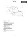
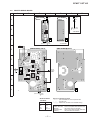
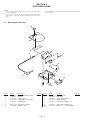
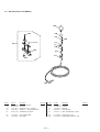
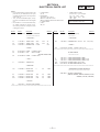
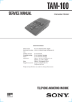
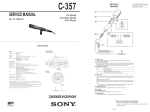
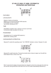
1
ECM-T115/T145
SERVICE MANUAL
US Model
Canadian Model
AEP Model
E Model
Ver 1.0 1999. 02
PHOTO : ECM-T115
PHOTO : ECM-T145
SPECIFICATIONS
ELECTRET CONDENSER MICROPHONE
MICROFILM
SERVICE NOTE
Notes on Chip Component Replacement
• Never reuse a disconnected chip component.
• Notice that the minus side of a tantalum capacitor may be
damaged by heat
—2—
SECTION 1
GENERAL
—3—
This section is extracted
from instruction manual.
ECM-T115/T145
SECTION 2
DIAGRAMS
2-1. SCHEMATIC DIAGRAM
TOTAL CURRENT : 0.21mA
LITHIUM BATTERY
Note on Schematic Diagram:
• All capacitors are in µF unless otherwise noted. pF: µµF
50 WV or less are not indicated except for electrolytics
and tantalums.
• All resistors are in Ω and 1/4 W or less unless otherwise
specified.
•
%
: indicates tolerance.
• C : panel designation.
• Signal path.
F : MIC
—4—
ECM-T115/T145
2-2. PRINTED WIRING BOARD
1
3
2
4
UNIT BOARD
A
5
6
7
UNIT BOARD
MIC1
(SIDE A)
MIC1
(SIDE B)
B
D10
MIC
OUT
D10
MINI
PLUG
T145 MODEL
C10
1-671-999-
11
C
11
(11)
1-671-999-
MINI
PLUG
(MIC OUT)
(11)
T115 MODEL
J1
MIC IN
AMP BOARD (SIDE A)
AMP BOARD (SIDE B)
R13
E
BATTERY
CHECK
LAMP
D2
S1
S1
POWER
D1
F
JC1
D3
D
ON
LITHUM
BATTERY
CR-2025
3V
R3
OFF
C1
C2
C14
R1
G
11
H
11
(11)
1-672-000-
1-672-000-
(11)
16
(MIC OUT)
MINI
PLUG
• Semiconductor
Location
Ref. No.
Location
D1
D2
D3
D10
F-2
F-2
D-2
B-4, A-6
—5—
Note on Printed Wiring Board:
• X : parts extracted from the component side.
®
•
: Through hole.
• b : Pattern from the side which enables seeing.
Caution:
Pattern face side:
(SIDE B)
Parts face side:
(SIDE A)
Parts on the pattern face side seen from
the pattern face are indicated.
Parts on the parts face side seen from
the parts face are indicated.
SECTION 3
EXPLODED VIEWS
NOTE:
• -XX, -X mean standardized parts, so they may have some differences
from the original one.
• Items marked “*” are not stocked since they are seldom required for
routine service. Some delay should be anticipated when ordering these
items.
•
The mechanical parts with no reference number in the exploded views
are not supplied.
3-1. BATTERY BOX SECTION
5
4
3
6
7
2
8
9
10
1
11
#1
Ref. No.
1
2
3
4
5
* 6
7
Part No.
Description
1-790-104-11
2-545-592-01
2-545-593-01
X-2542-165-1
2-545-588-01
CORD, MICROPHONE (1 CORE)
BUSHING
SHEET, SHIELD
CASE (UPPER) ASSY, BATTERY
KNOB, SWITCH
A-4542-561-A AMP BOARD, COMPLETE
2-545-589-01 TERMINAL, PLUS
Remarks
12
Ref. No.
Part No.
Description
8
9
10
11
12
2-545-590-01
2-545-599-01
2-545-586-01
2-545-587-01
2-545-601-01
TERMINAL, MINUS
SHEET, BLIND
CASE (LOWER), BATTERY
HOLDER, BATTERY
LABEL, MODEL NUMBER (T115)
12
#1
2-545-606-01 LABEL, MODEL NUMBER (T145)
7-685-103-19 SCREW +P 2 × 5 TYPE2 NON-SLIT
—6—
Remarks
3-2. MIC SECTION (T115 MODEL)
58
not supplied
57
56
MIC1
59
not supplied
55
54
52
53
51
Ref. No.
Part No.
Description
51
52
53
54
* 55
1-790-102-11
X-2542-079-1
3-704-197-72
2-545-584-01
4-916-272-01
CORD, MICROPHONE (1 CORE)
CLIP ASSY
SCREW (M1.4X4.5), LOCKING
BASE, MICROPHONE
SPACER
Remarks
Ref. No.
Part No.
Description
56
57
58
* 59
MIC1
2-543-437-01
3-309-597-31
2-545-583-01
1-671-999-11
8-814-294-00
REGISTER
SCREW (1.4), TAPPING,PRECISION
COVER, MICROPHONE
UNIT BOARD
MICROPHONE CAPSULE C-1053
—7—
Remarks
3-3. MIC SECTION (T145 MODEL)
105
103
106
107
108
not supplied
MIC1
101
D10
109
102
110
111
104
112
Ref. No.
Part No.
Description
101
102
103
104
105
A-4540-185-A
X-2542-079-1
3-704-197-12
3-309-597-51
X-2542-166-1
CLIP ASSY, HOLDER
CLIP ASSY
SCREW (M1.4X2.0), LOCKING
SCREW (1.4), TAPPING,PRECISION
SCREEN ASSY, WINDOW
106
107
2-545-564-01 CASE, MICROPHONE
2-545-595-01 NET, INNER
Remarks
Ref. No.
Part No.
Description
108
109
110
111
112
2-545-596-01
2-536-803-01
2-545-592-01
2-545-591-01
1-790-103-11
SPACER
STOPPER
BUSHING
CASE, BUSHING
CORD, MICROPHONE (1 CORE)
D10
MIC1
8-719-056-29 DIODE 015AZ4.7-TPL3
8-814-294-00 MICROPHONE CAPSULE C-1053
—8—
Remarks
SECTION 4
ELECTRICAL PARTS LIST
NOTE:
• Due to standardization, replacements in the
parts list may be different from the parts
specified in the diagrams or the components
used on the set.
• -XX, -X mean standardized parts, so they
may have some difference from the original
one.
• Items marked “*” are not stocked since they
are seldom required for routine service.
Some delay should be anticipated when
ordering these items.
•
•
•
Ref. No.
Part No.
*
A-4542-561-A AMP BOARD, COMPLETE
********************
CAPACITORS:
uF: µF
RESISTORS
All resistors are in ohms.
METAL: metal-film resistor
METAL OXIDE: Metal Oxide-film resistor
F: nonflammable
COILS
uH: µH
Description
Remarks
1-119-749-11 TANTAL. CHIP
1-104-908-11 TANTAL. CHIP
1-164-222-11 CERAMIC CHIP
8-719-072-95 DIODE
8-719-064-07 LED
D3
8-719-056-29 DIODE
33uF
47uF
0.22uF
20%
20%
4V
4V
25V
Part No.
1-671-999-11 UNIT BOARD (T115)
**********
Description
Remarks
1-163-009-11 CERAMIC CHIP 0.001uF
10%
50V (T115)
D10
8-719-056-29 DIODE
015AZ4.7-TPL3 (T115)
************************************************************
015AZ3.9-X-TPL3
SML-310LTT86
(BATTERY CHECK LAMP)
015AZ4.7-TPL3
MISCELLANEOUS
***************
1
1-790-104-11 CORD, MICROPHONE (1 CORE)
51
1-790-102-11 CORD, MICROPHONE (1 CORE) (T115)
112
1-790-103-11 CORD, MICROPHONE (1 CORE) (T145)
D10
8-719-056-29 DIODE 015AZ4.7-TPL3 (T145)
MIC1
8-814-294-00 MICROPHONE CAPSULE C-1053
************************************************************
1-764-624-51 JACK(MIC IN)
1-216-864-11 METAL CHIP
When indicating parts by reference number,
please include the board name.
< DIODE >
< RESISTOR >
JC1
SEMICONDUCTORS
In each case, u: µ, for example:
uA...: µA... , uPA... , µPA... ,
uPB... , µPB... , uPC... , µPC... ,
uPD..., µPD...
*
C10
< JACK >
J1
UNIT
< CAPACITOR >
< DIODE >
D1
D2
•
Ref. No.
< CAPACITOR >
C1
C2
C14
AMP
0
5%
1/16W
10K
220
3.9K
5%
5%
5%
1/16W
1/16W
1/16W
ACCESSORIES & PACKING MATERIALS
********************************
< RESISTOR >
R1
R3
R13
1-216-833-11 METAL CHIP
1-216-813-11 METAL CHIP
1-216-828-11 METAL CHIP
< SWITCH >
S1
1-692-397-21 SWITCH, SLIDE (POWER)
************************************************************
—9—
3-865-088-11 MANUAL, INSTRUCTION
(ENGLISH, FRENCH, GERMAN, SPANISH, DUTCH,
SWEDISH, ITALIAN, PORTUGAL)
ECM-T115/T145
Sony Corporation
9-924-973-11
Personal A&V Products Company
— 10 —
99B1677-1
Printed in Japan ©1999.2
Published by Quality Engineering Dept.
(Shinagawa)