1
User’s Guide
3922 496 31331 August 2009 v1.0
Prod
Prog
Cam +Floor
Eng
Camera
Communication
On Air
Base
Station
Camera Base Station
LDK 4582
HD Fiber Base Station
Camera
Connected
Test
Declaration of Conformity
We, Grass Valley Nederland B.V., Kapittelweg 10, 4827 HG Breda, The
Netherlands, declare under our sole responsibility that this product is in
compliance with the following standards:
- EN60065 : Safety
- EN55103-1: EMC (Emission)
- EN55103-2: EMC (Immunity)
following the provisions of:
a. the Low Voltage directive 2006/95/EC
b. the EMC directive 2004/108/EC
FCC Class A Statement
This product generates, uses, and can radiate radio frequency energy and if
not installed and used in accordance with the instructions, may cause
interference to radio communications.
It has been tested and found to comply with the limits for a class A digital
device pursuant to part 15 of the FCC rules, which are designed to provide
reasonable protection against such interference when operated in a
commercial environment.
Operation of this product in a residential area is likely to cause interference in
which case the user at his own expense will be required to take whatever
measures may be required to correct the interference.
Copyright
Copyright Grass Valley Nederland B.V. 2009. Copying of this document and
giving it to others, and the use or communication of the contents thereof, are
forbidden without express authority. Offenders are liable to the payment of
damages. All rights are reserved in the event of the grant of a patent or the
registration of a utility model or design. Liable to technical alterations in the
course of further development.
Trademarks
Grass Valley and Infinity are trademarks of Grass Valley, Inc. All other
tradenames referenced are service marks, trademarks, or registered
trademarks of their respective companies.
Website
Visit the Grass Valley public website to download the latest user’s guide
updates and additional information about your broadcast product:
www.grassvalley.com
Table of contents
Chapter 1 – Introduction
1.1
1.2
1.3
Technology. . . . . . . . . . . . . . . . . . . . . . . . . . . . . . . . . . . . . . . . . . . . . . . . . . . . . . . . . . 11
1.1.1 Fiber transmission . . . . . . . . . . . . . . . . . . . . . . . . . . . . . . . . . . . . . . . . . . . . . . . 11
1.1.2 Modular construction . . . . . . . . . . . . . . . . . . . . . . . . . . . . . . . . . . . . . . . . . . . . . 12
1.1.3 Audio and intercom . . . . . . . . . . . . . . . . . . . . . . . . . . . . . . . . . . . . . . . . . . . . . . 12
Features . . . . . . . . . . . . . . . . . . . . . . . . . . . . . . . . . . . . . . . . . . . . . . . . . . . . . . . . . . . . 13
Packing/unpacking . . . . . . . . . . . . . . . . . . . . . . . . . . . . . . . . . . . . . . . . . . . . . . . . . . . . 14
Chapter 2 – Installation
2.1
2.2
2.3
2.4
2.5
2.6
Control bus . . . . . . . . . . . . . . . . . . . . . . . . . . . . . . . . . . . . . . . . . . . . . . . . . . . . . . . . . . 15
Power supply . . . . . . . . . . . . . . . . . . . . . . . . . . . . . . . . . . . . . . . . . . . . . . . . . . . . . . . . 15
2.2.1 Base Station earthing. . . . . . . . . . . . . . . . . . . . . . . . . . . . . . . . . . . . . . . . . . . . . 17
Connecting the studio intercom system . . . . . . . . . . . . . . . . . . . . . . . . . . . . . . . . . . 17
Connecting the studio signalling . . . . . . . . . . . . . . . . . . . . . . . . . . . . . . . . . . . . . . . . 18
2.4.1 ISO, On Air and Call signals . . . . . . . . . . . . . . . . . . . . . . . . . . . . . . . . . . . . . . . . 18
External audio level control . . . . . . . . . . . . . . . . . . . . . . . . . . . . . . . . . . . . . . . . . . . . 24
Auxiliary connections . . . . . . . . . . . . . . . . . . . . . . . . . . . . . . . . . . . . . . . . . . . . . . . . . 25
2.6.1 Private data . . . . . . . . . . . . . . . . . . . . . . . . . . . . . . . . . . . . . . . . . . . . . . . . . . . . 25
Chapter 3 – Setup
3.1
3.2
3.3
3.4
3.5
Base Station controls and indicators . . . . . . . . . . . . . . . . . . . . . . . . . . . . . . . . . . . . . 27
Setting up the Base Station . . . . . . . . . . . . . . . . . . . . . . . . . . . . . . . . . . . . . . . . . . . . 28
3.2.1 Using the internal BS menu to set up the Base Station . . . . . . . . . . . . . . . . . . 28
3.2.2 Using the OCP 400 to set up the Base Station . . . . . . . . . . . . . . . . . . . . . . . . . 30
Using the Base Station system menu . . . . . . . . . . . . . . . . . . . . . . . . . . . . . . . . . . . . 31
3.3.1 Entering the system menu . . . . . . . . . . . . . . . . . . . . . . . . . . . . . . . . . . . . . . . . 31
3.3.2 Finding your way . . . . . . . . . . . . . . . . . . . . . . . . . . . . . . . . . . . . . . . . . . . . . . . . 32
3.3.3 Leaving the Systems Menu . . . . . . . . . . . . . . . . . . . . . . . . . . . . . . . . . . . . . . . . 32
3.3.4 Making changes. . . . . . . . . . . . . . . . . . . . . . . . . . . . . . . . . . . . . . . . . . . . . . . . . 33
3.3.5 Using the Recall File to undo changes. . . . . . . . . . . . . . . . . . . . . . . . . . . . . . . . 33
3.3.6 Base Station user levels . . . . . . . . . . . . . . . . . . . . . . . . . . . . . . . . . . . . . . . . . . 33
3.3.7 Video menu - special features . . . . . . . . . . . . . . . . . . . . . . . . . . . . . . . . . . . . . . 34
Setting up reference and timing. . . . . . . . . . . . . . . . . . . . . . . . . . . . . . . . . . . . . . . . . 35
3.4.1 Output signal processing . . . . . . . . . . . . . . . . . . . . . . . . . . . . . . . . . . . . . . . . . . 35
3.4.2 Adjustment procedure for HD timing . . . . . . . . . . . . . . . . . . . . . . . . . . . . . . . . 36
3.4.3 Adjustment procedure for SD timing . . . . . . . . . . . . . . . . . . . . . . . . . . . . . . . . . 37
Intercom set up . . . . . . . . . . . . . . . . . . . . . . . . . . . . . . . . . . . . . . . . . . . . . . . . . . . . . . 38
3.5.1 Base Station - studio interface set-up . . . . . . . . . . . . . . . . . . . . . . . . . . . . . . . . 38
3.5.2 Base Station headset set-up . . . . . . . . . . . . . . . . . . . . . . . . . . . . . . . . . . . . . . . 39
3.5.3 Voice mail . . . . . . . . . . . . . . . . . . . . . . . . . . . . . . . . . . . . . . . . . . . . . . . . . . . . . 40
LDK 4582 HD Fiber Base Station User’s Guide (v1.0)
3
Chapter 4 – Maintenance
4.1
4.2
Diagnostics . . . . . . . . . . . . . . . . . . . . . . . . . . . . . . . . . . . . . . . . . . . . . . . . . . . . . . . . . . 41
4.1.1 Base Station indicators . . . . . . . . . . . . . . . . . . . . . . . . . . . . . . . . . . . . . . . . . . . 41
4.1.2 Fiber transmission diagnostics. . . . . . . . . . . . . . . . . . . . . . . . . . . . . . . . . . . . . . 42
4.1.3 Sync/Encoder HD board diagnostics . . . . . . . . . . . . . . . . . . . . . . . . . . . . . . . . . 43
Replacements. . . . . . . . . . . . . . . . . . . . . . . . . . . . . . . . . . . . . . . . . . . . . . . . . . . . . . . . 44
4.2.1 Board locations . . . . . . . . . . . . . . . . . . . . . . . . . . . . . . . . . . . . . . . . . . . . . . . . . 44
4.2.2 Replacing the power unit . . . . . . . . . . . . . . . . . . . . . . . . . . . . . . . . . . . . . . . . . . 44
4.2.3 Replacing dust filters . . . . . . . . . . . . . . . . . . . . . . . . . . . . . . . . . . . . . . . . . . . . . 46
Chapter 5 – Menu structure and contents
5.1
5.2
Menu structure. . . . . . . . . . . . . . . . . . . . . . . . . . . . . . . . . . . . . . . . . . . . . . . . . . . . . . . 49
5.1.1 Top menu structure . . . . . . . . . . . . . . . . . . . . . . . . . . . . . . . . . . . . . . . . . . . . . . 49
5.1.2 Video menu structure . . . . . . . . . . . . . . . . . . . . . . . . . . . . . . . . . . . . . . . . . . . . 50
5.1.3 Monitoring menu structure . . . . . . . . . . . . . . . . . . . . . . . . . . . . . . . . . . . . . . . . 50
5.1.4 Audio/Intercom menu structure. . . . . . . . . . . . . . . . . . . . . . . . . . . . . . . . . . . . . 51
5.1.5 SDTV menu structure . . . . . . . . . . . . . . . . . . . . . . . . . . . . . . . . . . . . . . . . . . . . 52
5.1.6 System menu structure . . . . . . . . . . . . . . . . . . . . . . . . . . . . . . . . . . . . . . . . . . . 53
5.1.7 Files menu structure . . . . . . . . . . . . . . . . . . . . . . . . . . . . . . . . . . . . . . . . . . . . . 54
5.1.8 Diagnostics menu structure. . . . . . . . . . . . . . . . . . . . . . . . . . . . . . . . . . . . . . . . 55
Menu contents . . . . . . . . . . . . . . . . . . . . . . . . . . . . . . . . . . . . . . . . . . . . . . . . . . . . . . . 56
5.2.1 Video menu . . . . . . . . . . . . . . . . . . . . . . . . . . . . . . . . . . . . . . . . . . . . . . . . . . . . 56
5.2.2 Monitoring menu . . . . . . . . . . . . . . . . . . . . . . . . . . . . . . . . . . . . . . . . . . . . . . . . 57
5.2.3 Audio/intercom menu . . . . . . . . . . . . . . . . . . . . . . . . . . . . . . . . . . . . . . . . . . . . 58
5.2.4 SDTV menu . . . . . . . . . . . . . . . . . . . . . . . . . . . . . . . . . . . . . . . . . . . . . . . . . . . . 60
5.2.5 System menu. . . . . . . . . . . . . . . . . . . . . . . . . . . . . . . . . . . . . . . . . . . . . . . . . . . 61
5.2.6 Files menu . . . . . . . . . . . . . . . . . . . . . . . . . . . . . . . . . . . . . . . . . . . . . . . . . . . . . 63
5.2.7 Diagnostics menu . . . . . . . . . . . . . . . . . . . . . . . . . . . . . . . . . . . . . . . . . . . . . . . 64
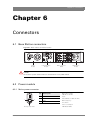
Chapter 6 – Connectors
6.1
6.2
6.3
6.4
6.5
6.6
4
Base Station connectors . . . . . . . . . . . . . . . . . . . . . . . . . . . . . . . . . . . . . . . . . . . . . . . 67
Power module . . . . . . . . . . . . . . . . . . . . . . . . . . . . . . . . . . . . . . . . . . . . . . . . . . . . . . . 67
6.2.1 Mains power connector . . . . . . . . . . . . . . . . . . . . . . . . . . . . . . . . . . . . . . . . . . . 67
Communication module . . . . . . . . . . . . . . . . . . . . . . . . . . . . . . . . . . . . . . . . . . . . . . . 68
6.3.1 Digital audio output (1+2) connector . . . . . . . . . . . . . . . . . . . . . . . . . . . . . . . . . 68
6.3.2 Digital audio output (3+4) connector . . . . . . . . . . . . . . . . . . . . . . . . . . . . . . . . . 68
6.3.3 Audio output (1 & 2) connectors . . . . . . . . . . . . . . . . . . . . . . . . . . . . . . . . . . . . 68
6.3.4 Intercom connector . . . . . . . . . . . . . . . . . . . . . . . . . . . . . . . . . . . . . . . . . . . . . . 69
6.3.5 Signalling connector. . . . . . . . . . . . . . . . . . . . . . . . . . . . . . . . . . . . . . . . . . . . . . 69
6.3.6 Auxiliary connector. . . . . . . . . . . . . . . . . . . . . . . . . . . . . . . . . . . . . . . . . . . . . . . 70
6.3.7 Network connector . . . . . . . . . . . . . . . . . . . . . . . . . . . . . . . . . . . . . . . . . . . . . . 70
BNC connector board . . . . . . . . . . . . . . . . . . . . . . . . . . . . . . . . . . . . . . . . . . . . . . . . . 71
6.4.1 External video input connectors. . . . . . . . . . . . . . . . . . . . . . . . . . . . . . . . . . . . . 71
6.4.2 Main video output connectors . . . . . . . . . . . . . . . . . . . . . . . . . . . . . . . . . . . . . . 72
6.4.3 SD and monitoring connectors . . . . . . . . . . . . . . . . . . . . . . . . . . . . . . . . . . . . . 74
6.4.4 Teleprompter and reference connectors . . . . . . . . . . . . . . . . . . . . . . . . . . . . . . 74
Transmission module . . . . . . . . . . . . . . . . . . . . . . . . . . . . . . . . . . . . . . . . . . . . . . . . . 74
6.5.1 Hybrid fiber connector . . . . . . . . . . . . . . . . . . . . . . . . . . . . . . . . . . . . . . . . . . . . 74
LDK 4541/10 Engineering intercom module (option) . . . . . . . . . . . . . . . . . . . . . . . . 75
6.6.1 Headset connector (front side) . . . . . . . . . . . . . . . . . . . . . . . . . . . . . . . . . . . . . 75
LDK 4582 HD Fiber Base Station User’s Guide (v1.0)
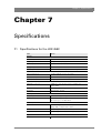
Chapter 7 – Specifications
7.1
7.2
7.3
Specifications for the LDK 4582 . . . . . . . . . . . . . . . . . . . . . . . . . . . . . . . . . . . . . . . . . 77
Specifications for optional modules . . . . . . . . . . . . . . . . . . . . . . . . . . . . . . . . . . . . . 79
Dimensions . . . . . . . . . . . . . . . . . . . . . . . . . . . . . . . . . . . . . . . . . . . . . . . . . . . . . . . . . 80
LDK 4582 HD Fiber Base Station User’s Guide (v1.0)
5
End-of-life product recycling
Grass Valley’s innovation and excellence in product design also extends to the programs we’ve
established to manage the recycling of our products. Grass Valley has developed a
comprehensive end-of-life product take back program for recycle or disposal of end-of-life
products. Our program meets the requirements of the European Union’s WEEE Directive and
in the United States from the Environmental Protection Agency, individual state or local
agencies.
Grass Valley’s end-of-life product take back program assures proper disposal by use of Best
Available Technology. This program accepts any Grass Valley branded equipment. Upon
request, a Certificate of Recycling or a Certificate of Destruction, depending on the ultimate
disposition of the product, can be sent to the requester.
Grass Valley will be responsible for all costs associated with recycling and disposal, including
freight, however you are responsible for the removal of the equipment from your facility and
packing the equipment ready for pickup.
For further information on the Grass Valley product take back system please contact Grass
Valley at + 800 80 80 20 20 or +33 1 48 25 20 20 from most other countries. In the US and
Canada please call 800-547-8949 or 530-478-4148. Ask to be connected to the EH&S
Department. In addition, information concerning the program can be found at:
www.grassvalley.com/environment
6
LDK 4582 HD Fiber Base Station User’s Guide (v1.0)
Important information
Read these instructions carefully and retain them for future reference.
During installation and operation of this equipment, local building safety and fire protection
standards must be observed.
Before connecting the equipment to the power supply of the installation, verify the proper
functioning of the protective earth lead.
Whenever it is likely that safe operation is impaired, the apparatus must be made inoperative
and secured against any unintended operation. The appropriate servicing authority must then
be informed. For example, safety is likely to be impaired if the apparatus fails to perform the
intended function or shows visible damage.
Any changes or modifications not expressly approved in this manual could void your authority
to operate this equipment.
Cautions and Warnings
Read and comply with the warning and caution notices that appear in the manual.
– Warnings indicate danger that requires correct procedures or practices to prevent
death or injury to personnel.
– Cautions indicate procedures or practices that should be followed to prevent damage
or destruction to equipment or property.
Warnings
To prevent fire or shock hazard, do not expose the unit to rain or moisture.
To avoid electrical shock, do not remove covers or panels. Refer servicing to qualified
personnel only.
In case of an emergency ensure that the power is disconnected.
Use only fuses of the type and rating specified.
Connect the product only to a power source with the specified voltage rating.
The Base Station must always be connected to protective earth. Do not interrupt the
protection conductor inside or outside the unit. Do not disconnect the protective earth
terminal. Intentional interruption is prohibited and is likely to make the unit dangerous.
To prevent risk of overheating, ventilate the units correctly.
For safety reasons the Base Station must be mounted in a 19-inch rack which has safety covers
according to IEC65. When two Base Stations are mounted above each other, the minimum
distance between them must be 50 mm or the rack must be force-air cooled.
LDK 4582 HD Fiber Base Station User’s Guide (v1.0)
7
Fiber-optic transmission units
CLASS 1
LASER PRODUCT
LASER KLASSE 1
PRODUKT
Laser safety statement (Europe)
Fiber-optic transmission units are classified as a "CLASS 1 Laser Product" according to EN
60825-1, Safety of Laser products. Class 1 laser products are considered safe and do not
result in biological hazard if used according to the instructions.
Laser safety statement (US)
Fiber-optic transmission units are classified as a "CLASS 1 Laser Product" according to
21CFR 1040.10 of the US Food and Drug Administration (FDA) Center for Devices and
Radiological Health.
Use of controls, adjustments or performance of procedures other than those specified herein
may result in hazardous radiation exposure.
To ensure proper use of this product, please read this instruction manual carefully and retain
for future reference. Should the unit ever require maintenance, contact an authorized service
location.
Fiber-optic cable precautions
Fiber-optic cables and connectors are easily damaged; take the following percautions into
account:
– Do not bend the cable beyond the minimum permissible bend range specified for the
cable.
– Avoid kinks in the cable.
– Avoid subjecting the cable to a high tension force (even momentarily).
– Do not twist the cable when connecting it to equipment.
– Insert connectors straight and fully into their corresponding sockets.
– In fiber-optic cable systems always put the dust caps on cable and panel connectors
immediately after disconnecting a cable. Keep the dust caps clean.
8
LDK 4582 HD Fiber Base Station User’s Guide (v1.0)
Cleaning fiber-optic connectors
WARNING
Never clean an optical connector attached to a fiber that is carrying light.
Particles of foreign matter on the tip of a ferrule can have a disabling effect on fiber-optic
transmission. Fiber-optic connectors need to be cleaned every time they are mated and
unmated; it is essential that fiber-optic users develop the necessary discipline to always clean
the connectors before they are mated.
Use a commerially available cleaning kit specifically designed for fiber-optic connectors and
follow the manufacturer's instructions carefully.
•
The connector sections to be cleaned include the tips and sides of ferrules, the interior
walls of alignment sleeves, and the interior and exterior of connector shells.
•
For plugs, the interior surfaces of alignment sleeves and the tips of ferrules are to be
cleaned with a cleaning stick treated with the appropriate fluid. (Cleaning sticks with a
slender design are available that allow alignment sleeves to be cleaned without having to
detach them.)
•
For jacks, it is important to clean both the tips and sides of the completely protruding
ferrules.
•
Both the male and female connector shells tend to attract dust and metal particles, so it is
important to clean both the insides and outsides.
•
The fiber end face and ferrule must be absolutely clean before it is inserted into a
transmitter or receiver.
•
Mate the connector immediately! Don't let the connector lie around and collect dust
before mating.
•
Air can be used to remove lint or loose dust from the port of a transmitter or receiver to be
mated with the connector. Never insert any liquid into the ports.
LDK 4582 HD Fiber Base Station User’s Guide (v1.0)
9
Base Station earthing
The rear of the unit has two separate screw terminals for protective earth
video earth
(VE). These are normally connected by a metal strap.
(PE) and
VE
Metal strap
PE
The protective earth terminal is internally connected to the protective earth conductor of the
power cable. In normal circumstances the connection between the protective earth and the
video earth should not be broken. If required, the central earth connection wire of the studio
can be connected to terminal PE in accordance with VDE regulation 0800/part2.
Only if the studio (or OB van) is equipped with separate protective and video earth systems
may the metal strap be removed. Under these circumstances the video earth terminal must be
connected to the central functional earth potential (video earth) of the studio. This earth
potential should have functional protective and noiseless earth (FPE) qualities as stated in the
VDE regulation 0800/part2. A low impedance interconnection of both earth conductors must
be provided at the central studio earthing point.
Mains lead wiring for UK users
The wires in the mains lead are coloured in accordance with the following code:
GREEN and YELLOW- EARTH
BLUE- NEUTRAL
BROWN- LIVE
As the colours of the wires in the mains lead of this apparatus may not correspond with the
coloured markings identifying the terminals in your plug proceed as follows:
•
The wire coloured GREEN AND YELLOW must be connected to the terminal on the plug
marked with the letter E or by the safety earth symbol
or coloured GREEN or GREEN
AND YELLOW.
•
The wire coloured BROWN must be connected to the terminal marked with the letter L or
coloured RED.
•
The wire coloured BLUE must be connected to the terminal marked with the letter N or
coloured BLACK.
Ensure that your equipment is connected correctly - if you are in any doubt consult a
qualified electrician.
10
LDK 4582 HD Fiber Base Station User’s Guide (v1.0)
Chapter 1 - Introduction
Chapter 1
Introduction
1.1
Technology
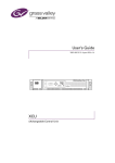
The LDK 4582 HD Fiber Base Station is the perfect interface between your HD camera and the
rest of your system. The heavy-duty base station provides state-of-the-art technology in a
compact package. The high level of modularity guarantees ideal matching with any type of
application; you can use the system in a studio or for mobile field production, for HD or for SD
production.
The Base Station is only 2U high yet offers full broadcast functionality and quality.The low
height means that rack space is saved. Its low power consumption and efficient internal
cooling eliminate the need for space between adjacent units. Sliding rails are additionally
available for easy access to the back panel. The wings on either side of the back panel protect
the connectors from damage, including the hybrid fiber connector. The hybrid fiber connector
itself can easily be mounted at different angles to suit all mounting requirements.
Operational controls
You can access the Base Station menu, which contains all operational settings, from an
Operational Control Panel. In addition to the operational menu, the installation and service
menus can be activated from the Base Station by pressing a switch behind the front panel. The
Base Station is compatible with all existing control system components.
1.1.1 Fiber transmission
The HD fiber system allows video transmission and remote control of cameras up to a distance
of 4,000 m (13,000 ft) and beyond, using industry standard fiber optic cable. It is based on
30 MHz full-bandwidth 4:2:2 transmission (Y/Cr/Cb components). All video and data signals are
transmitted digitally to ensure long cable runs without any loss of quality.
LDK 4582 HD Fiber Base Station User’s Guide (v1.0)
11
Chapter 1 - Introduction
1.1.2 Modular construction
The modular concept makes it easy to expand the functionality by simply adding new modules.
Quick exchange of the modules for servicing or the ability to swap modules between Base
Stations is another benefit.
External video inputs
The external video input module provides two analog video inputs and loop-through analog
outputs. The signal can be PAL or NTSC, and does not need to be clamped. It can also be nonsynchronized. The external video input module can be replaced in future by a digital one.
High quality SD outputs
Besides standard high-definition outputs, the Base Station can be optionally equipped with
simultaneous high-end SD outputs. This offers ultimate flexibility: produce in SD one day, and
in HD the next, or do both simultaneously. The optional LDK 4530/40 High Quality SD module
adds three 270 Mb/s SDI outputs.
1.1.3 Audio and intercom
The audio and advanced intercom module provides 4-channel intercom, 2-channel digital audio
(AES/EBU compliant) and 2-channel high-quality analog audio from the camera. The audio
channels from the camera head are passed to the different outputs via balanced line drivers on
the module for clean transparent sound. Both analog audio channels are available as digital
outputs on the Base Station. Gain levels can be externally controlled.
In the installation menu of the Base Station, a choice is provided between a 4-wire or a 2-wire
intercom system. A 1kHz test-tone generator and voicemail are available. The voicemail stores
messages from the Program, Production or Engineering channels for the camera operator.
By adding the engineering intercom module, a 5-channel full-featured intercom is possible. The
engineering intercom module provides a 2-channel intercom between camera operator and
engineering. The module fits into the front of the unit and facilitates the plugging in of a
headset and level adjustment for both ear muffs. It is ideal for a simple intercom facility in a
standalone mode of operation, or to expand the 4-channel advanced intercom to a 5-channel
intercom.
12
LDK 4582 HD Fiber Base Station User’s Guide (v1.0)
Chapter 1 - Introduction
1.2
Features
•
Low height: only 2U high, 19-inch rack unit.
•
Flexible due to its modular construction.
•
The digital transmission backbone and power module meet the most demanding
broadcasting needs.
•
3 channels SD-SDI or HD-SDI return video inputs available.
•
Heavy-duty concept with low power consumption, ideal for Outside Broadcast (OB) vans.
•
Fiber allows video transmission and remote control of cameras up to a distance of
4,000 m (13,000 ft) and beyond.
•
Full camera control via the C2IP Ethernet-based network.
•
Two-wire or four-wire intercom compatible with international standards.
•
HD and simultaneous high-quality SD outputs (optional).
LDK 4582 HD Fiber Base Station User’s Guide (v1.0)
13
Chapter 1 - Introduction
1.3
Packing/unpacking
Inspect the shipping container for evidence of damage immediately after receipt. If the
shipping container or cushioning material is damaged, it should be kept until the contents of
the shipment have been checked for completeness and the units have been checked
mechanically and electrically. The shipping container should be placed upright and opened from
the top. Remove the cushioning material and lift out the contents. The contents of the
shipment should be checked against the packing list. If the contents are incomplete, if there is
mechanical damage or defect, or if the units do not perform correctly when unpacked, notify
your sales or service centre within eight days. If the shipping container shows signs of damage
or stress, notify the carrier as well.
If a unit is being returned to for servicing, try to use the containers and materials of the original
packaging. Attach a tag indicating the type of service required, return address, model number,
full serial number and the return number which will be supplied by your service centre. If the
original packing can no longer be used, the following general instructions should be used for
repacking with commercially available materials:
14
1.
Wrap unit in heavy paper or plastic.
2.
Use a strong shipping container.
3.
Use a layer of shock-absorbing material around all sides of the unit to provide firm
cushioning and prevent movement inside container.
4.
Seal shipping container securely.
5.
Mark shipping container “FRAGILE” to ensure careful handling.
LDK 4582 HD Fiber Base Station User’s Guide (v1.0)
Chapter 2 - Installation
Chapter 2
Installation
2.1
Control bus
The Base Stations are each connected to the control network hub or router via an Ethernet
cable (straight-through, not cross-over). The OCP 400 operational control panels and, if
required the MCP 400 Master Control Panel, are also connected to the Ethernet network via a
hub or router.
An OCP 400 operational control panel can also be connected directly to the Base Station using
a cross-over Ethernet cable.
The IP address and other options for the Ethernet connection can be set up in the Base
Station System menu. These items can also be set up remotely using a network
configuration tool such as Grass Valley’s NetConfig.
☞
2.2
Note
By default the Ethernet connection is set up for automatic IP assignment.
Power supply
Caution
Connect the Base Station only to a power source with the specified voltage rating. Use only
fuses of the type and rating specified.
The Base Station must always be connected to protective earth. Do not interrupt the
protection conductor inside or outside the unit. Do not disconnect the protective earth
terminal. Intentional interruption is prohibited and is likely to make the unit dangerous.
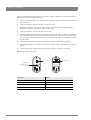
Before connecting your unit to the power supply check the fuse type (230 VAC or 115 VAC)
on the IEC power connector at the rear of the Base Station.
If the fuse type shown corresponds to your power supply voltage, connect the power supply
for the Base Station to the IEC connector at the rear.
LDK 4582 HD Fiber Base Station User’s Guide (v1.0)
15
Chapter 2 - Installation
If the fuse type does not correspond to your power supply voltage you must change the fuses
before connecting the supply as follows:
1.
Insert a small screwdriver into the slot above the pins of the IEC connector and unclip the
fuse holder unit.
2.
Insert you finger under the indication unit and pull it out.
3.
Rotate the indication unit 180° so that the correct indication for you voltage supply is
displayed at the back of the Base Station (230 or 115).
4.
Slide the indication unit securely back into its slot.
5.
Insert the appropriate fuses into the alternative fuse holder which is delivered separately
with the Base Station (4 AT fuses are 22 mm long and fit into the 230 fuse holder; 10 AT
fuses are 32 mm long and fit into the 115 fuse holder). The type of fuse holder is marked
on the holder.
6.
Slide the fuse holder securly back into the IEC connector until it clips into place.
7.
Check again that you have used the correct fuses and that the corresponding indication is
shown.
8.
Connect the power supply for the Base Station to the IEC connector at the rear.
Fuse type
230
230
Figure 2-1. Base Station fuses
Indication unit
Insert small
screwdriver here
to open clip
16
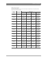
Function
Value
Mains input voltage
230 VAC or 115 VAC
Fuses
4AT (230 VAC) or 10AT (115 VAC)
Mains frequency
47 to 63 Hz
Power consumption
270 Watt (470 VA)
LDK 4582 HD Fiber Base Station User’s Guide (v1.0)
Chapter 2 - Installation
2.2.1 Base Station earthing
The rear of the unit has two separate screw terminals for protective earth
video earth
(VE). These are normally connected by a metal strap.
(PE) and
Figure 2-2. Base Station earthing
VE
Metal strap
PE
The protective earth terminal is internally connected to the protective earth conductor of the
power cable. In normal circumstances the connection between the protective earth and the
video earth should not be broken. If required, the central earth connection wire of the studio
can be connected to terminal PE in accordance with VDE regulation 0800/part2.
Only if the studio (or OB van) is equipped with separate protective and video earth systems
may the metal strap be removed. Under these circumstances the video earth terminal must be
connected to the central functional earth potential (video earth) of the studio. This earth
potential should have functional protective and noiseless earth (FPE) qualities as stated in the
VDE regulation 0800/part2. A low impedance interconnection of both earth conductors must
be provided at the central studio earthing point.
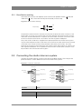
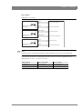
2.3
Connecting the studio intercom system
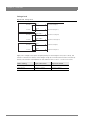
Connect the studio intercom system to the rear of the Base Station. The wiring of the
panel connector is shown below for two-wire and four-wire systems.
Figure 2-3. Intercom connection
Two-wire
Four-wire
Housing
8
Housing
15
Prod +-
+ Eng in/out
9
Function
- Prod in/out
+
1
8
Housing
Prog in ret
Prog in
15
Housing
+ Eng in/out
Eng in ret
Eng in
Prod in ret
Prod in
9
1
- Prod in/out
+
Value
2-wire
Signal level
0 dBu (RMS)
Load impedance
200 Ω
DC level
40 VDC (max.)
LDK 4582 HD Fiber Base Station User’s Guide (v1.0)
17
Chapter 2 - Installation
Function
Value
4-wire
2.4
Output signal level
+6 or 0 dBu (RMS) selectable
Output impedance
50 Ω (max.), symmetrical
Input signal level
+6 or 0 dBu (RMS) selectable
Impedance
9 KΩ (min.), symmetrical
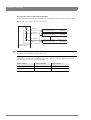
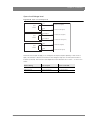
Connecting the studio signalling
Connect the studio signalling system to the rear of the Base Station. The wiring of the
panel connector is shown below:
Figure 2-4. Signalling connector
1
9
Call out send
Call out return
ISO in send
ISO in return
On Air send
On Air return
Audio 1 level
Audio 2 level
GND
Preview out send
Preview out return
Call in send
Call in return
15
8
+5 VDC
Housing
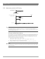
2.4.1 ISO, On Air and Call signals
There are several connection methods for the ISO (On Air Yellow), On Air and Call signalling
functions: dry contact, common ground, voltage level and open circuit/voltage level.
A selection in the SYSTEM > SIGNALLING menu allows you to make the activity state of the
function (Active or Inactive) correspond to a particular input signal. There are two leads for each
connection - Send and Return.
18
Function
Send pin
Return pin
ISO
3
11
On Air
4
12
Call
2
10
LDK 4582 HD Fiber Base Station User’s Guide (v1.0)
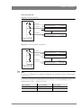
Chapter 2 - Installation
Dry contact
Figure 2-5. Dry contact
ISO 1a
ISO in ext. send (pin 3)
External ISO signalling
(dry contact)
ISO 1b
ISO in ext. return (pin 11)
On-Air (Tally) 1a
On-Air in ext. (pin 4)
External On-Air signalling
(dry contact)
On-Air (Tally) 1b
On-Air in ext. return (pin 12)
Call 1a
Call in ext. (pin 5)
External Call signalling
(dry contact)
☞
Call 1b
Call in ext. return (pin 13)
Note
A common return (not ground!) can be used for all three functions (ISO, On Air and Call)
If a contact is closed, the corresponding function is Active or Inactive, depending on the
selection the SYSTEM > SIGNALLING menu:
Menu setting
Input is shorted:
Input is open:
LH (low-high)
Function is Active
Function is Inactive
HL (high-low)
Function is Inactive
Function is Active
LDK 4582 HD Fiber Base Station User’s Guide (v1.0)
19
Chapter 2 - Installation
Dry contact with multiple Base Stations
This is an example of an On Air signalling with multiple Base Station using common contact.
Figure 2-6. Dry contact with common contact
On-Air (Tally) 1
On-Air in ext. send (pin 4)
On-Air in ext. return (pin 12)
Signalling connector
Base Station 1
On-Air in ext. send (pin 4)
On-Air in ext. return (pin 12)
Signalling connector
Base Station 2
On-Air in ext. send (pin 4)
On-Air in ext. return (pin 12)
Signalling connector
Base Station n
On-Air (Tally) 2
On-Air (Tally) n
Common
External On-Air signalling
(common contact)
☞
Note
Use either Send or Return only, but do not mix.
If a contact is closed, the corresponding function is Active or Inactive, depending on the
selection the SYSTEM > SIGNALLING menu:
20
Menu setting
Input is shorted:
Input is open:
LH (low-high)
Function is Active
Function is Inactive
HL (high-low)
Function is Inactive
Function is Active
LDK 4582 HD Fiber Base Station User’s Guide (v1.0)
Chapter 2 - Installation
Common ground
Figure 2-7. Common ground
On-Air (Tally) 1
On-Air in ext. (pin 4)
On-Air in ext. return (pin 12)
Signalling connector
Base Station 1
On-Air in ext. (pin 4)
On-Air in ext. return (pin 12)
Signalling connector
Base Station 2
On-Air in ext. (pin 4)
On-Air in ext. return (pin 12)
Signalling connector
Base Station n
On-Air (Tally) 2
On-Air (Tally) n
External On-Air signalling
(common ground contact)
Figure 2-8. Common ground using returns
On-Air (Tally) 1
On-Air in ext. (pin 4)
On-Air in ext. return (pin 12)
Signalling connector
Base Station 1
On-Air in ext. (pin 4)
On-Air in ext. return (pin 12)
Signalling connector
Base Station 2
On-Air in ext. (pin 4)
On-Air in ext. return (pin 12)
Signalling connector
Base Station n
On-Air (Tally) 2
On-Air (Tally) n
External On-Air signalling
(common ground contact)
☞
Note
Ensure that a reliable ground coupling exists between the control device ground and the Base
Station ground.
If a contact is closed, the corresponding function is Active or Inactive, depending on the
selection the SYSTEM > SIGNALLING menu:
Menu setting
Input is shorted:
Input is open:
LH (low-high)
Function is Active
Function is Inactive
HL (high-low)
Function is Inactive
Function is Active
LDK 4582 HD Fiber Base Station User’s Guide (v1.0)
21
Chapter 2 - Installation
Voltage level
Figure 2-9. Voltage level
ISO 1a
0 .. 2.5 VDC +
ISO in ext. send (pin 3)
ISO 1b
4 .. 24 VDC -
ISO in ext. return (pin 11)
On-Air (Tally) 1a
0 .. 2.5 VDC +
On-Air in ext. send (pin 4)
On-Air (Tally) 1b
4 .. 24 VDC -
On-Air in ext. return (pin 12)
Call 1a
0 .. 2.5 VDC +
Call in ext. send (pin 5)
Call 1b
4 .. 24 VDC -
Call in ext. return (pin 13)
Apply a DC voltage to the inputs (respect polarity). If the voltage is low (0 to 2.5 VDC), the
function is Active (or Inactive). If the voltage is high (4 to 24 VDC) the function is Inactive (or
Active). The function state depends on the selection the SYSTEM > SIGNALLING menu:
22
Menu setting
Input is 0 to 2.5V:
Input is 4 to 24V:
LH (low-high)
Function is Active
Function is Inactive
HL (high-low)
Function is Inactive
Function is Active
LDK 4582 HD Fiber Base Station User’s Guide (v1.0)
Chapter 2 - Installation
Open circuit/Voltage level
Figure 2-10. Open circuit/Voltage level
ISO 1a
ISO in ext. send (pin 3)
Open/
4..24 VDC
ISO 1b
ISO in ext. return (pin 11)
On-Air (Tally) 1a
On-Air in ext. send (pin 4)
Open/
4..24 VDC
On-Air (Tally) 1b
On-Air in ext. return (pin 12)
Call 1a
Call in ext. send (pin 5)
Open/
4..24 VDC
Call 1b
Call in ext. return (pin 13)
Leave the circuit open or apply a DC voltage to the inputs (respect polarity). If the circuit is
open, the function is Active (or Inactive). If the voltage is high (4 to 24 VDC) the function is
Inactive (or Active). The function state depends on the selection the SYSTEM > SIGNALLING
menu:
Menu setting
Input is open
Input is 4 to 24V
OH (open-high)
Function is Active
Function is Inactive
HO (high-open)
Function is Inactive
Function is Active
LDK 4582 HD Fiber Base Station User’s Guide (v1.0)
23
Chapter 2 - Installation
2.5
External audio level control
The camera audio level for channel 1 and 2 can be externally controlled by the base
station. In the camera menu, go to the INSTALL > AUDIO > AUDIO GAIN MODE item and
select Ext.
On the OCP 400, push the SETUP button and choose the Cam(era) submenu. Use the
NEXT button to scroll to the REM AUDIO menu and select Rem.
Apply a DC voltage to pins 6 and 14 of the signalling connector to control the levels of
audio channels 1 and 2 respectively, as shown in the figure below:
Figure 2-11. Audio level control
Mic/Line
Audio 1 level (pin 6)
Audio 2 level (pin 14)
Mic/+5 VDC (pin 7)
-22/+12dBu
-28/+4dBu
1k
1k
1k
-34/-2dBu
+4.3V
+3.7V
+3.1V
1k
+2.5V
-40/-8dBu
-46/-14dBu
1k
1k
-52/-20dBu
+1.9V
+1.3V
1k
+0.7V
-58/-26dBu
1k
-64/-32dBU
0V
GND (pin 15)
The actual audio level depends on the setting of the selection switches at the back panel of the
camera adapter. When Mic is selected, the maximum gain level is -64 dBu, while maximum
Line level is -32 dBu.
24
LDK 4582 HD Fiber Base Station User’s Guide (v1.0)
Chapter 2 - Installation
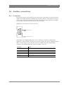
2.6
Auxiliary connections
2.6.1 Private data
Private data channels can be used for the transmission of serial data via the transmission
cable. For example, electronic scriptboard or character data for a video display unit or pan
and tilt data can be transmitted to the camera. The input and output signals are available
on the auxiliary connectors of the camera and Base Station.
Figure 2-12. Private data on auxiliary connector
9
5
Private data in
6
1
Private data out
Remember that the propagation-delay times are different for different cable lengths,
especially if a return signal is involved. At maximum lengths of 2,400 m (7,900 ft) the total
delay is at least 25 μs and can be more than 30 μs depending on the type of cable.
The duty cycle difference between input and output is max. 5%.
Function
Value
Bitrate
100 kbits/s
Input level
TTL, possible RS-232 ("0"= 0V +/- 0.5V; "1"= 5V +/- 0.5V)
Input impedance
100 kΩ
Output impedance
150 Ω
Max. load
approx. 1 kΩ
LDK 4582 HD Fiber Base Station User’s Guide (v1.0)
25
Chapter 2 - Installation
26
LDK 4582 HD Fiber Base Station User’s Guide (v1.0)
Chapter 3 - Setup
Chapter 3
Setup
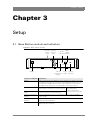
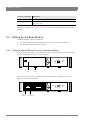
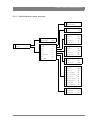
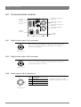
3.1
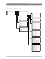
Base Station controls and indicators
Figure 3-1. Base Station controls
Intercom Intercom
volume selection
switch
control
Base
On Air Station
indicators indicator
Prod
Prog
Cam +Floor
Eng
Camera
Communication
On Air
Base
Station
Test
Camera
Connected
Camera Base Station
Power
Camera
communication switch
indicator
Display
Camera
indicators
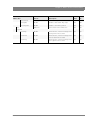
Control or indicator Description
Display
During normal operation the display shows the number of the camera connected
to the Base Station. When the set-up control (located behind the left front cover)
is activated, the display shows a two letter code to identify the setup function .
The display can be switched on or off via the Base Station menu system.
Intercom volume control
Adjusts the volume of the selected intercom
channel being monitored on the connector below.
Intercom selection
switch
Use this switch to select the intercom channel
that is monitored on the connector below.
Camera communication
indicator
This green LED lights when the communications between Camera and Base
Station are OK.
On=Air and ISO
indicators
The red LED lights when the Camera is On Air. If the Camera is selected as ISO
Camera the yellow LED lights.
Power switch
Switches the power supply to the Base Station on and off. A built-in light lights to
indicate that the power is On.
LDK 4582 HD Fiber Base Station User’s Guide (v1.0)
Only available when the
optional LDK 4541
2-channel Engineering
intercom module is installed.
27
Chapter 3 - Setup
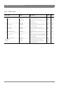
Control or indicator Description
Base Station indicator
This green LED lights when the Base Station is operationally ready.
Camera indicators
These bi-colour Test LEDs lights red or yellow to indicate the camera and
transmission status.
Refer to the chapter “Maintenance” on page 41 for more detailed information about these
indicators.
3.2
Setting up the Base Station
The Base Station is set up using either:
1.
The internal Base Station menu behind the front cover of the Base Station or
2.
An OCP 400 attached to the Base Station
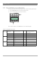
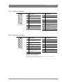
3.2.1 Using the internal BS menu to set up the Base Station
Push the clasp at the bottom of the left front cover to the left and remove the front cover to
access the Rotary/Push button on the Data Board:
Prod
Prog
Cam +Floor
Eng
Camera
Communication
On Air
Base
Station
Test
Camera
Connected
Camera Base Station
Left front
cover
Open
clasp
Rock the button to the left or right to select the required item. The display shows the
abbreviation of the selected item.
Prod
Prog
Cam +Floor
Eng
Camera
Communication
On Air
Base
Station
Test
Camera
Connected
Camera Base Station
Segment
Rotary /
display Push button
28
LDK 4582 HD Fiber Base Station User’s Guide (v1.0)
Chapter 3 - Setup
Menu items
There are four items that can be accessed via the internal menu:
System menu
When “NN” is displayed, push the Rotary/Push button twice to enter the
System Menu. The Rotary/Push button can be used to navigate through the
menu system, however, it is more convenient to use the OCP 400 connected to the Base
Station.
☞
Note
When accessed from the internal menu, the Base Station user level is set to Operator.
Camera number
When “CA” is displayed, push the Rotary/Push button to enter the selection
mode. Rock the button to the left or right to select an available camera
number. Push the Rotary/Push button to set the new camera number. The Base Station
automatically resets and the new camera number is shown in the display.
Subcarrier Phase adjusment
When “SC” is displayed, push the Rotary/Push button to enter the subcarrier
adjustment mode. Rock the button to the left or right to shift the subcarrier
phase. If you continue to rock the button, the shift change occurs in bigger steps. Push the
Rotary/Push button to leave the subcarrier adjustment mode.
☞
Note
This item is only available when a reference signal is present.
H-Phase adjustment
When “HP” is displayed, push the Rotary/Push button to enter the H-Phase
adjustment mode. Rock the button to the left or right to shift the H-Phase. If
you continue to rock the button, the shift change occurs in bigger steps. Push the Rotary/
Push button to leave the H-Phase adjustment mode.
☞
Note
This item is only available when a reference signal is present.
LDK 4582 HD Fiber Base Station User’s Guide (v1.0)
29
Chapter 3 - Setup
3.2.2 Using the OCP 400 to set up the Base Station
The OCP 400 can be used to set up the base station instead of the Rotary/Push button.
1.
Push the Setup Menu button on the OCP to open the menu.
2.
Push the selection button to choose the BS submenu.
Files
Recall
Auto
Exit
Setup
1
Toggle
Diag
OCP
BS
Cam
Prev
Next
2
The BS submenu appears. Use the Next button to view subsequent pages.
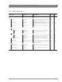
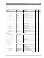
Table 3-2. Base Station set-up menu
Menu
Selections
Function
BS
MONITORING
Picture monitor selection
Level
S
Possible values
CVBS, R,G,B, Y, EXT1, EXT2,
Y/EXT1, Y/EXT2
-
Next
MENU
BS internal menu enable
S
H PHASE
Adjustment H-Phase
B
0..99
SC COARSE
Adjustment Subcarrier phase
(coarse)
B
0, 90, 180, 270
SC FINE
Adjustment Subcarrier phase
(coarse)
B
0..99
NOTCH LVL
Notch Depth (composite out only)
B
0..99
NOTCH
Notch function (composite out
only)
B
On, Off
-
Next
-
30
LDK 4582 HD Fiber Base Station User’s Guide (v1.0)
Chapter 3 - Setup
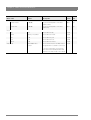
Select the MENU item of the BS menu to access the internal menu of the Base Station. The
internal menu appears on the Base Station Text output and CVBS output (if switched on).
Table 3-3. Base Station internal menu
Menu
Selections
Function
Level
BS internal menu
UP*
UP menu
S
DOWN*
DOWN menu
S
SELECT
Select item
S
-
* Or use the rotary contol on the OCP to move up or down through the menu.
☞
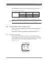
3.3
Note
When accessed from the OCP 400, the Base Station user level is set to Operator.
Using the Base Station system menu
The menu system is used for configuring the base station. As there are a large number of
functions and set-up options available, it may require some time for you to become
familiar with them all.
The System Menu video signal is available on the Text output of the base station. The
System Menu text can also be superimposed on the CVBS output if desired.
3.3.1 Entering the system menu
Use the Rotary/Push button behind the left front cover to control some basic set-up
functions and to navigate through the menu system. The system functions of the base
station are grouped into menus and sub-menus. Rotate the Rotary/Push button to the left
or right to select the Systems Menu. The display shows the abbreviation “NN”. Push the
Rotary/Push button twice to enter. The Main menu appears on the monitor.
Figure 3-4. Main menu
MENU OFF
Video
Monitoring
Audio/Intercom
SDTV
System
Root
Files
Diagnostics
LDK 4582 HD Fiber Base Station User’s Guide (v1.0)
31
Chapter 3 - Setup
The main menu screen shows five items and the name of the menu. One more item is hidden
but becomes visible when you scroll down. A cursor shows your position in the menu. The
Rotary/Push button moves the cursor up and down.
3.3.2 Finding your way
Use the Rotary/Push button to move the cursor through the menu items. If a double arrow
(>>) is visible, then pressing the Rotary/Push button brings you one level lower in the
menu system. Only five items are visible in each menu. Scroll up or down to see any
additional items.
When you first enter a menu (other than the main menu) the cursor is positioned next to the
first item. The TOP and PREVIOUS entries are not immediately visible but are located above
the first item. Use the Rotary control to scroll up to them.
•
Select TOP to bring you back to the MAIN menu.
•
Select PREVIOUS to go back to the menu that you were in before the current one.
Figure 3-5. System menu
TOP
PREVIOUS
Camera Number 1
Camera Power On
MCP Available Yes
Yellow On Air
Std
Timing
System
Clock
Video Mode 10i59
Teleprompter Off
The SYSTEM menu above shows the items displayed when you first enter the menu and the
other items that are available by scrolling up or down with the Rotary control.
3.3.3 Leaving the Systems Menu
If you are deep within the menu structure, follow these steps to leave:
•
If necessary move the cursor to the left most column with the Rotary/Push button.
•
Scroll upwards until the cursor points to TOP (this is the main menu).
•
Press the Rotary/Push button. The cursor now points to the Menu off item of the MAIN
menu.
•
Press the Rotary/Push button to leave the system menu.
This is the recommended way of leaving the system menu. The menu system disappears after
a few seconds when you stop navigating. This delay can be set in the MONITORING > MENU
menu. However, when you enter the system menu again you enter at the last position of the
cursor and not at the top of main menu. To prevent confusion the next time you enter the
system menu, it is advisable to leave the system menu by returning to the main menu (TOP)
and selecting MENU OFF.
32
LDK 4582 HD Fiber Base Station User’s Guide (v1.0)
Chapter 3 - Setup
3.3.4 Making changes
To find out where to change a function, consult the List of System Menu Functions at the
end of this section to find out under which menu group or subgroup the function is
located. If the cursor points to an item (and there are no double arrows to indicate a submenu) then the item pointed to has a value. The value can be:
•
a toggle value (only two values)
•
a list value (more than two values)
•
an analogue value (variable from 00 to 99)
•
or unavailable (---).
If the value is unavailable it cannot be changed. This is indicated by three dashes (---). This can
occur, for example, when a function is switched off. The analogue values associated with that
function are then unavailable. If there are only two values associated with the function, then
pressing the Rotary/Push button toggles between these two values. If a value is displayed next
to a function that is one of several possible values, then pressing the Rotary/Push button
places the cursor in a list menu indicating the value currently selected. Use the Rotary/Push
button to point to a new value.
Press the Rotary/Push button to return the cursor to the function list. If an analogue value is
displayed next to a function name, then pressing the Rotary/Push button places the cursor in
front of the value and the Rotary/Push button is used to change the analogue value. Press the
Rotary/Push button to return the cursor to the function list.
3.3.5 Using the Recall File to undo changes
If you make changes to the settings in the Systems menu and you decide not to keep
them, use the Recall File function to recall a standard or stored set of values for the
parameters. These files are available in the FILES menu.
3.3.6 Base Station user levels
The menu items are divided into two user levels. The operator level (O) is default
accessible. Menu items with user level Install (I) are only accessible if the menu level is
set to Install. To enter the Install level proceed as follows:
1.
Enter the menu.
2.
Navigate to the MONITORING > MENU > MENU LEVEL item.
3.
Set the Menu level to Inst.
The purpose of the user levels is to restrict the set of functions which can be changed by
whoever is using the Base Station. In this way a the danger of the operator accidentally
changing critical functions while shooting is reduced.
The chapter “Menu structure and contents” on page 49 indicates which functions are available
at each user level.
☞
Note
When accessed from the internal BS menu, the Base Station user level is set to Operator
while the user level is set to Install when accessed from the OCP 400.
LDK 4582 HD Fiber Base Station User’s Guide (v1.0)
33
Chapter 3 - Setup
3.3.7 Video menu - special features
Auto lighting
The Auto Lighting item of the the video menu compensates for variations in the frequency
of the power supply used for gas discharge lamps (fluorescent or HMI lighting). The
frequency of power supply generators can vary from the nominal value. This variation
affects the lighting which in turn affects the colour balance. If camera system and lighting
are supplied by the same power source, then the base station auto lighting function can
automatically adjust the exposure to follow the variations and maintain a constant colour
balance. This correction only works when the camera exposure time is set to the 50 Hz or
60 Hz position.
Gain adjustment
The Gain Adjustments item of the the video menu is a special item. It combines menu
items from various other menus to help you when you are adjusting the gain. It should
only be used when carrying out the gain adjustments on the Sync/Encoder board in
conjunction with the procedure given.
34
LDK 4582 HD Fiber Base Station User’s Guide (v1.0)
Chapter 3 - Setup
3.4
Setting up reference and timing
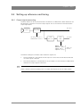
3.4.1 Output signal processing
The base station can be synchronized with HD Trilevel or SD Black Burst. Both references can
be adjusted to match the SD and HD output signals. This is an overview of the base station
output signal paths:
Camera
HD output
Base Station
processing
HD Trilevel reference or
SD Black Burst reference
Progr.
delay
Scaler
HD > SD
1080i50 ~ 845 μs
1080i59.94 ~ 766 μs
720p50 ~ 826 μs
720p59.94 ~ 751 μs
SD output
approx. 25
HD lines
The default settings for the base station reference signals are:
☞
•
The first reference is HD Trilevel: the HD output is in time with the HD Trilevel while the
SD output signal is delayed.
•
The second reference is SD Black Burst: the SD output is in time with the SD Black Burst
while the HD output signal is advanced.
Note
There is always a processing delay in the SD output with respect to the HD video outputs.
LDK 4582 HD Fiber Base Station User’s Guide (v1.0)
35
Chapter 3 - Setup
3.4.2 Adjustment procedure for HD timing
HD output with
Trilevel reference
t0
H-phase range
HD Trilevel reference
HD output with Black
Burst reference
1 frame
t0
H-phase range
SD Black Burst reference
shift
t1
SD output
HD > SD
processing
delay
✎
Programmable delay
Tip
If HD Trilevel reference is used, the HD output is in sync with the HD Trilevel reference. A
timing offset can be set with the SYSTEM > TIMING > H PHASE COARSE and H PHASE COARSE
items of the base station menu.
HD output with Black Burst reference
The SD output is in sync with the Black Burst reference. The HD output signal is ahead in time
with respect to the Black Burst reference. The HD signal can be shifted with respect to the
Black Burst reference, until it is in time with the HD output. The delay between HD and SD
outputs remains the same after this adjustment.
☞
36
1.
Enter the base station menu in service mode:
MONITORING > MENU > MENU LEVEL > INST > SERVICEMODE > EXEC > YES
2.
Adjust the Black Burst timing with the following items:
SYSTEM > TIMING > SHIFT > PIXEL HIGH ,PIXEL LOW ,LINES HIGH,LINES LOW
Note
This adjustment must be done for each video mode. The last setting for each of these modes
will be memorized.
LDK 4582 HD Fiber Base Station User’s Guide (v1.0)
Chapter 3 - Setup
3.4.3 Adjustment procedure for SD timing
The SD output is delayed with respect to the HD output. The SD output can be further delayed
until both outputs are synchronous, but shifted over a single frame. The adjustment of the
delay ranges from the minimal processing time to more than 1 frame.
1.
Enter the base station menu in service mode:
MONITORING > MENU > MENU LEVEL > INST > SERVICEMODE > EXEC > YES
2.
After factory delivery there is a fixed minimum delay between HD and SD outputs:
SDTV > TIMING > COMP
3.
Set the SDTV Timing to Variable:
SDTV > TIMING > VAR
4.
Adjust the SD output delay using the following items:
SDTV > TIMING > SYNC SHIFT PIXELS and SHIFT LINES
☞
Note
☞
Note
✎
Tip
This adjustment must be done for each video mode. The last setting for each of these modes
will be memorized.
The CVBS viewing output is a non-standard output and the SD output delay adjustment does
not apply to this output.
HD-Trilevel sync does not contain 4-field (NTSC) or 8-field (PAL) sequence information and
therefore will be random. If this is required Black Burst reference should be used.
LDK 4582 HD Fiber Base Station User’s Guide (v1.0)
37
Chapter 3 - Setup
3.5
Intercom set up
The studio camera systems offer extensive intercom facilities between cameraman, tracker
(floor man), Base Station and studio. To help you set up and operate the intercom system, the
following controls are available:
•
Base Station menu system
•
Camera head menu system
•
Base Station front panel selection switch (optional)
•
Camera head adapter rear panel
•
Camera head switches
When setting up a system it is usually more convenient to use an OCP 400 to select your
preferences in both the Base Station and camera head menu systems.
☞
Note
For a fully-featured intercom system, the Base Station must be fitted with an LDK 4540/10
2 channel audio & 2/4-wire intercom module and an LDK 4541/10 2 channel Engineering
intercom module, both of which are optionally available. If either of these modules is absent,
the associated features outlined below are not available.
3.5.1 Base Station - studio interface set-up
A four-wire or a two-wire studio system can be connected to the Base Station. In the Base
Station AUDIO > INTERCOM menu, select the Wire Mode for engineering (ENG), production
(PROD) and programming (PROG). By default these values are set to four-wire.
Isolate
The isolate function completely disconnects the Base Station intercom from the studio
system. The function can be switched locally or remotely via the OCP 400.
Levels
In the four-wire mode the menu gives you a choice of either a 0dBu or a +6dBu signal level. In
the two-wire mode this level is set to 0dBu.
38
•
Set the input and output intercom levels for the PROD and ENG channels. The range is 00
to 99; default is 50.
•
Set the input level for the PROG channel.
•
Set the levels for the sidetone in a two-wire system in this menu.
LDK 4582 HD Fiber Base Station User’s Guide (v1.0)
Chapter 3 - Setup
3.5.2 Base Station headset set-up
☞
Note
The headset facilities are only available on Base Stations fitted with the LDK 4541/10 2 channel
Engineering intercom module which is optionally available.
A headset connected to the front of the Base Station is set-up via the AUDIO > INTERCOM
menu of the Base Station using the ENG headset submenu. In this menu you can select a
12 VDC phantom supply for the headset microphone and set the microphone level to 0 dB or
+20 dB.
The cameraman microphone signal and the tracker (floor) microphone signal can be individually
switched on for the headset and the levels for each can be set. You can switch on a sidetone
from the Base Station microphone and set its level.
The Base Station microphone signal is added to the ENG channel. Use the MIC ENG-OUT
function in the menu to send it to the studio engineering channel. Use the MICTOENG-CAM
function to send it to the camera.
Operation
The signal to the headset is controlled with a switch in the front of the Base Station which
selects the intercom signal to be heard in the Base Station headset. The choices are:
•
PROD (production)
•
PROG (programming)
•
CAM+FLOOR (cameraman and tracker)
•
ENG (engineering)
If CAM+FLOOR is selected, the signal that is heard depends on the values set in the ENG
Headset submenu for the CAMERAMIC and TRACKERMIC signals in the AUDIO > INTERCOM
menu of the Base Station.
☞
Note
If you have selected to operate a bi-directional private data channel between the Base Station
and the camera in the AUDIO > INTERCOM menu of the Base Station, then the tracker
microphone signal is not available in the Base Station and the Program signal is not available in
the camera.
LDK 4582 HD Fiber Base Station User’s Guide (v1.0)
39
Chapter 3 - Setup
3.5.3 Voice mail
Voice Mail is an intercom message storage function.
☞
Note
Voice mail is only available if the AUDIO > INTERCOM > INTERCOM > CALL item is set to voice.
Recording
Recording starts automatically at the start of a message. A new message erases the previous
recorded message. The maximum message length is 16 seconds. Longer messages are
recorded in a retroloop. Only the last 16 seconds are available for playback. Select the intercom
channels to be recorded via the Base Station menu items
AUDIO > INTERCOM > INTERCOM > VOICE MAIL > RECORD ENG, PROD and PROG.
☞
Note
The voice mail box can only contain one message. If voice mail recording starts from an other
intercom channel the previous message is erased.
Listening to the message
Push the camera call button to start playing out the recorded voice mail to the camera headset.
Push the call button again to stop playing the voice mail message.
40
LDK 4582 HD Fiber Base Station User’s Guide (v1.0)
Chapter 4 - Maintenance
Chapter 4
Maintenance
4.1
Diagnostics
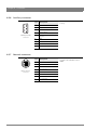
4.1.1 Base Station indicators
Figure 4-1. Base Station indicators
Camera
communication
indicator
Camera
indicators
Prod
Prog
Cam +Floor
Eng
Camera
On Air
Communication
Camera
Base
Station Test Connected
On Air/ISO Base Station
indicators
indicator
Camera communication indicator
This green LED lights when communication between camera and Base Station is OK.
On Air/ISO indicators
The red On Air LED lights when the camera is On Air. The yellow LED light when the
camera is selected as ISO camera.
Base Station indicator
This green LED lights when the Base Station is operationally ready.
LDK 4582 HD Fiber Base Station User’s Guide (v1.0)
41
Chapter 4 - Maintenance
Camera Test indicator
This bi-colour LED lights red or yellow to indicate the Camera and transmission status:
•
Red lights continuously – cable short circuit OR an interrupted cable core. On the
OCP 400, the Cable LED (red) lights continuously.
•
Red flashes – Cable open circuit (no camera is connected). On the OCP 400, the Cable
LED (red) flashes.
•
Yellow – Camera power was switched off from the OCP 400 or MCP 400.
Camera Connected indicator
This green LED lights when the camera is connected (and camera power is not switched off by
the OCP 400, MCP 400 or Base Station menu)
Communication
indicator
Camera Test
indicator
Cam Connected
indicator
Remark
off
off
green
Camera power is switched off by the
camera power switch.
off
yellow
off
Camera power is switched off by the
OCP 400, MCP 400 or BS menu.
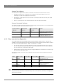
4.1.2 Fiber transmission diagnostics
First order diagnostics are available in both camera and base station menus. They are also
available on the control panels (OCP 400, MCP 400). The set of diagnostic information contains
four items (two items per direction: CAM --> BS and BS --> CAM):
•
Transmission status: this indicator provides a value of the optical power level, to inform
the user whether the optical attenuation level is acceptable or not. This status indication
has four values: OK, Critical, Error, No Signal
•
Optical margin level: This item indicates the guard before the connection is in error range.
The unit of this indication is dB.
The following table shows the status indications and the values that correspond with these
indications:
☞
42
Status
Power (mW)
Power (dBm)
Margin (dBm) Description
OK
> 0.040
> -14
18
Fiber transmission is ok
Critical
0.015 .. 0.040
-18 .. -14
18
Signal level is critical but the system
will work.
Error
0.005 .. 0.015
-14 .. -23
18
Signal level is not OK: a working
system is not guaranteed.
No signal
< 0.005
< -23
18
No signal received.
Note
The power/margin indicator is refreshed every one or two seconds. However, a full signal loss
will be shown directly.
LDK 4582 HD Fiber Base Station User’s Guide (v1.0)
Chapter 4 - Maintenance
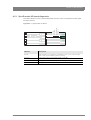
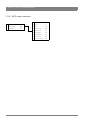
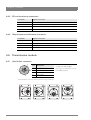
4.1.3 Sync/Encoder HD board diagnostics
The LED indicators on the Sync/Encoder board show the status of the board and the signal
locking as follows:
Init. Fail
Sync Lock
Ext. Ref. Avail.
Burst Lock
Figure 4-2. Sync/Encoder HD board
Indicator
Description
Init. Fail
Lights (red) when a configuration or initialisation error occurs or when the bus
clock or video synchronization pulses are missing.
Sync Lock
Lights (green) when horizontal and vertical lock are OK.
Ext. Ref. Avail.
Lights (green) when an external synchronization signal is present.
Burst Lock
Lights (green) when the subcarrier/H-phase lock is OK.
LDK 4582 HD Fiber Base Station User’s Guide (v1.0)
43
Chapter 4 - Maintenance
4.2
Replacements
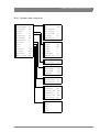
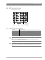
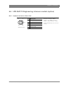
4.2.1 Board locations
Figure 4-3. Base Station board locations
Data
board
Digital output
board
Sync encoder
board
Engineering intercom
module (option)
fiber power
Prod
Prog
Cam +Floor
Eng
Camera
On Air
Communication
Camera
Base
Station Test Connected
Camera Base Station
Audio intercom
HQ SD
board
board (option)
Transmission
board
Power module
fiber
4.2.2 Replacing the power unit
Removing the power unit
•
Loosen the screw at the rear of the power unit.
•
With your thumb push up the lever, as shown below, and pull the power unit out of the
Base Station.
Figure 4-4. Removing the power unit
Camera
On Air
Communication
Camera
Base
Station Test Connected
Camera Base Station
44
LDK 4582 HD Fiber Base Station User’s Guide (v1.0)
Chapter 4 - Maintenance
Installing the Power Unit
•
Put the power unit into the guides and push until the lock clicks.
•
Check that the power unit is correctly locked.
•
Tighten the screw at the rear of the Power Unit.
WARNING
Make sure that the power unit is firmly placed and that the locking lever is in the correct
vertical position as indicated below.
Figure 4-5. Locking the power unit
Camera
On Air
Communication
Camera
Base
Station Test Connected
Camera Base Station
Wrong
Correct
LDK 4582 HD Fiber Base Station User’s Guide (v1.0)
45
Chapter 4 - Maintenance
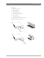
4.2.3 Replacing dust filters
Side-inlet
1.
Remove 4 screws.
2.
Slide back support with dust filter out of base station.
3.
Remove dust filter.
4.
Place clean dust filter in back support.
5.
Slide back support with dust filter into base station.
6.
Fix support with 4 screws.
Figure 4-6. Replacing side dust filters
46
LDK 4582 HD Fiber Base Station User’s Guide (v1.0)
Chapter 4 - Maintenance
Front-inlet
1.
Remove PCB front cover.
2.
Remove dust filter.
3.
Place clean dust filter.
4.
Put back PCB front cover.
5.
Remove front cover Power Unit.
6.
Remove dust filter.
7.
Place clean dust filter.
8.
Return front cover Power Unit to its position.
Figure 4-7. Replacing front dust filters
PCB front cover
Power Unit cover
LDK 4582 HD Fiber Base Station User’s Guide (v1.0)
47
Chapter 4 - Maintenance
48
LDK 4582 HD Fiber Base Station User’s Guide (v1.0)
Chapter 5 - Menu structure and contents
Chapter 5
Menu structure and contents
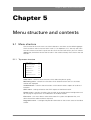
5.1
Menu structure
The structure of the main menus and their submenus are shown on the following pages.
The first column shows the user level: Install (“I”) or Operator (“O”). You only see menu
functions whose user level is equal to or less than the user level set on your unit. Where
appropriate, the default value of the function in the standard factory file is shown after the
function.
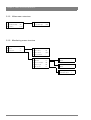
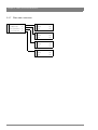
5.1.1 Top menu structure
Video menu
>>
Monitoring menu
>>
Audio/Intercom
>>
SDTV menu
>>
System menu
>>
Files menu
>>
Diagnostics menu
>>
Video menu - contains those functions which affect the picture quality.
Monitoring menu - contains the functions which determine how items in the video
monitor are displayed.
Audio/Intercom - contains those functions which control various aspects of audio and
intercom.
SDTV menu - settings related to the SDTV outputs of the Base Station.
System menu - contains functions that are used to set up the general configuration and
for carrying out adjustments and calibrations of the Base Station.
Files menu - this menu allows values to be stored in system and operator files, and
allows these files to be recalled as required.
Diagnostics menu - is designed to provide information on the current status of the Base
Station.
LDK 4582 HD Fiber Base Station User’s Guide (v1.0)
49
Chapter 5 - Menu structure and contents
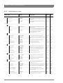
5.1.2 Video menu structure
I
Colour Bar
>>
O Colour Bar
Off
Ext Black Clamp
50
I
SMP
O Combine
Colour Bar Type
Field
5.1.3 Monitoring menu structure
O Monitoring Source Y
O Menu
>>
O Display
Time
O Status bar
>>
O Menu Time
10
O Menu Level
Oper.
O Service Mode
-
O Studio
>>
O Studio
Off
O Operator
>>
O Name
-
O Camrea number
Off
O Cable length
Off
O Operator
Off
O HD out text
>>
O Name
-
O Warning Y-pos
14
O CamName Y-pos
1
50
LDK 4582 HD Fiber Base Station User’s Guide (v1.0)
Chapter 5 - Menu structure and contents
5.1.4 Audio/Intercom menu structure
I
-
Cam Routing
-
-
Tracker Routing
-
O Source
Local
I
Isolate
Syst
I
Wire Mode
4wire
O Side Tone
50
I
Audio Level 1
6dB
O Level
6dB
I
Audio Level 2
6dB
I
In Ref Level
50
I
Out Ref Level
50
Wire Mode
4wire
Audio
>>
Test
>>
O Intercom
>>
Isolate
>>
I
Eng
>>
O Side Tone
50
Prod
>>
O Level
6dB
Prog
>>
I
In Ref Level
50
Eng Headset
>>
I
Out Ref Level
50
Call
Call
Voice Mail
>>
I
Wire Mode
4wire
LDK 4582 HD Fiber Base Station User’s Guide (v1.0)
O Level
50
I
In Ref Level
6dB
O Phantom Power
Off
O Mic Level
20dB
O Side Tone
50
O Mic to Headset
On
O Cam to Headset
On
O Cam Volume
50
O Tracker to Headset
On
O Tracker Volume
50
O Mic Eng-Out
On
O Mic to Eng-Cam
On
O Record Eng
On
O Record Prod
On
O Record Prog
On
51
Chapter 5 - Menu structure and contents
5.1.5 SDTV menu structure
52
O Contour
On
Contour
>>
O Source
Y
Aspect Ratio
16:9
O Level
10
Letterbox
Off
O Vertical Level
50
O Noise Slicer
6
O Coarse/Fine
25
O Level Depend.
25
O Soft Contour
On
O Soft Cont. Level
70
LDK 4582 HD Fiber Base Station User’s Guide (v1.0)
Chapter 5 - Menu structure and contents
5.1.6 System menu structure
Cable
>>
O % Max.Spec.Att.
128
O Camera Number
99
O Size
8mm
O Control Mode
C2IP
O Rem. Length (m)
5
IP Address
>>
O Rem. Length (ft)
5
Ethernet
>>
O Curr. Atten. (dB)
0
O Camera Power
On
O Length Unit
km
I
MCP Available
Yes
O Remaining Lngth
0
Signalling inputs
>>
Extern Video
>>
O IP Config Mode
Auto
Timing
>>
O IP digit 1
169
Clock
>>
O IP digit 2
254
I
Video Mode
mode
O IP digit 3
1
I
TV System
NTSC
O IP digit 4
1
I
Teleprompter
Off
O Subnet Mask
24
I
OCP Cont. Mode
HD
O Apply IP settings
busy
I
Ethernet Speed
10Mb
I
Ethernet Duplex
Auto
O Yellow On Air
Std
O Yellow On/Off
Lo/Hi
O On Air On/Off
Lo/Hi
O Call On/Off
Lo/Hi
I
Ext. Video Source
SDI
I
SDI Chroma Ext1
Off
I
SDI Chroma Ext2
Off
O H Phase Coarse
50
O H Phase Fine
50
O Subcarrier Coarse
180
O Subcarrier Fine
50
I
Subc H Ph. Coars.
180
I
Subc H. Ph. Fine
50
I
Day
-
I
Month
-
I
Year
-
I
Hour
-
I
Minute
-
LDK 4582 HD Fiber Base Station User’s Guide (v1.0)
53
Chapter 5 - Menu structure and contents
5.1.7 Files menu structure
54
User Oper. Files
>>
O Operator File
obs1
Std. Oper. Files
>>
O Recall
exec
User System Files
>>
O Store
exec
Std. System Files
>>
O Operator File
CUST
O Recall
exec
I
Store
exec
I
System File
sbs1
I
Recall
exec
I
Store
exec
I
System File
CUST
I
Recall
exec
I
Store
exec
LDK 4582 HD Fiber Base Station User’s Guide (v1.0)
Chapter 5 - Menu structure and contents
5.1.8 Diagnostics menu structure
Board ID
>>
<Info Board 1>
-
Board Diagnostics
>>
...
Transm. Diag.
>>
<Info Board n>
-
Comm. Diag.
>>
Power Board
>>
Sync Enc. Board
Data Board
Audio/Iintercom
>>
Eng Headset
Ext Video Input
O Triax Status
tshrt
O Fiber Status
tshrt
O Local Power St.
NtOK
>>
O Power Overheatd
Yes
>>
O Fan
OK
>>
O Ref. Available
None
>>
O Burst Lock
No
O Sync Lock
No
O Transm. System
Unkn
O Carrier Detected
No
O Firmware Status
-
O HDSDI Lock
Off
O Boot Software ID
0
O Analog Carr. Det.
Off
O Base Station 12nc
3307
O AGC Out Ok
Off
O Base Station St.
-
O Eth. MAC
-
O Cam Connected
No
O Eth. Link Type
Unk.
O OCP Connected
No
O Eth. Link State
Disc.
O MCP Connected
No
O C2IP Panels
0
O Self Test
exec
O Eng T. Tone Int.
-
O Prod T. Tone Int.
-
O Prog T. Tone Int.
-
O Eng T. Tone Stu.
-
O Prod T. Tone Stu
-
O Self Test
exec
O Test Intern
-
O Test Studio
-
O Test Tone Mic. BS
Off
O Test Tone Tr/Fr Mi
Off
O Test Tone Cam Mi
Off
O Carrier Eq. Ext1
No
O Carrier Rcve Ext1
No
O SDI Lock Ext1
No
O SDI TV Sys Ext1
625
O Carrier Eq. Ext1
No
O Carrier Rcve Ext1
No
O SDI Lock Ext1
No
LDK 4582 HD Fiber Base Station User’s Guide (v1.0)
55
Chapter 5 - Menu structure and contents
5.2
Menu contents
All items in the table are visible at the install user level. However, if an item is not relevant it is
not shown.
The Oper in the Level column indicates that this item is visible at the Operator user level; the
Install indicates that this item is visible at the Install user level.
The Scene in the File column indicates that the value of this item is stored in the Scene file; the
Sys indicates that the value of this item is stored in the System file; the Oper indicates that the
value of this item is stored in the Operator file.
In the Values column, the default values of the item are shown in bold.
5.2.1 Video menu
Menu item
Values
Description
Level
File
Colour Bar
On, Off
Turns colour bar on or off (when no camera
signal is present/detected)
Oper
Scene
Colour Bar Type
SMPTE-219, SMPTE, Full
Selects the colour bar type
Install
Sys
Pulse bar
On, Off
Install
Sys
Lighting
Optimal, Good, Fair, Poor, Selects AnyLight anti-flicker type. Only for
Extreme
LDK 4583 High Speed Base Station
Oper
-
Combine
Field, 2-line, 4-line
Oper
Scene
Colour Bar
56
Selects method of combining high-speed
phases for the viewing output. Only for
LDK 4583 High Speed Base Station
LDK 4582 HD Fiber Base Station User’s Guide (v1.0)
Chapter 5 - Menu structure and contents
5.2.2 Monitoring menu
Menu item
Values
Description
Level
File
Monitoring source
R, G, B, Y
Selects signal on monitoring HD output.
Oper
Scene
Display
On, Time
Selects the menu display to be permanently Oper
on (visible) or to disappear after set time.
Oper
Menu Time
5..99 (10)
Sets the length of time the menu is
displayed when the Display mode is set to
Time.
Oper
Oper
Menu Level
Oper, Inst, Serv
Sets the user access level for the menu.
Oper
-
Studio
On, Off
Shows the studio name in the status bar.
Oper
Oper
Name
<studio name>
Edit the studio name string value.
Oper
-
Studio
On, Off
Shows the operato’s name in the status bar. Oper
Oper
Name
<studio name>
Edit the operator’s name string value.
Oper
-
Camera number
On, Off
Shows the camera number in the status
bar.
Oper
Oper
Cable length
Off, Perc, Length, Atten
Shows the cable length in percentage used, Oper
length left or attenuation.
Oper
Warning Y-pos
1..14 (14)
Sets the vertical position of the warning
text.
Oper
-
CamName Y-pos
1..14 (1)
Sets the vertical position of the camera
name.
Oper
-
Menu
Status bar
Studio
Operator
HD Out Text
LDK 4582 HD Fiber Base Station User’s Guide (v1.0)
57
Chapter 5 - Menu structure and contents
5.2.3 Audio/intercom menu
Menu item
Values
Description
Level
File
Audio Level 1
0dB, 6dB
Selects studio audio attenuation for analog
audio input 1.
Install
Sys
Audio Level 2
0dB, 6dB
Selects studio audio attenuation for analog
audio input 2.
Install
Sys
Source
Local, Rmote
Local = settings are available in the base
station menu;
Rmote = settings are available in the MCP
Oper
Oper
Isolate
Isol, Syst
Isol = Isolate Prog and Prod intercom to
camera head with Eng available;
Syst = isolate is off
Install
Install
Wire Mode
2wire, 4wire
Selects studio intercom wiring mode.
Install
Sys
Side Tone
0..99 (50)
Sets side tone (headset feedback) volume
level.
Oper
Oper
Level
0dB, 6dB
Selects intercom channel attenuation.
Oper
Oper
In Ref Level
0..99 (50)
Sets input reference level.
Install
Sys
Out Ref Level
0..99 (50)
Sets output reference level.
Install
Oper
Wire Mode
2wire, 4wire
Selects studio intercom wiring mode.
Install
Sys
Side Tone
0..99 (50)
Sets side tone (feedback) volume level.
Oper
Oper
Level
0dB, 6dB
Selects intercom channel attenuation.
Oper
Oper
In Ref Level
0..99 (50)
Sets input reference level.
Install
Sys
Out Ref Level
0..99 (50)
Sets output reference level.
Install
Oper
Wire Mode
2wire, 4wire
Selects studio intercom wiring mode.
Install
Sys
Level
0dB, 6dB
Selects intercom channel attenuation.
Oper
Oper
In Ref Level
0..99 (50)
Sets input reference level.
Install
Sys
Phantom Power
On, Off
Turns microphone phantom power
(+12 VDC) on or off.
Oper
Oper
Mic Level
0dB, 20dB
Sets headset microphone sensitivity level.
Oper
Oper
Side Tone
0..99 (50)
Sets headset side tone (feedback) level.
Oper
Oper
Mic to Headset
On, Off
Turns headset side tone on or off.
Oper
Oper
Cam to Headset
On, Off
Turns camera ENG channel to headset
routing on or off.
Oper
Oper
Cam Volume
0..99 (50)
Sets camera ENG channel to headset level.
Oper
Oper
Tracker to Headset
On, Off
Tracker ENG channel to headset.
Oper
Oper
Audio
Intercom
Isolate
Eng
Prod
Prog
Eng Headset
58
LDK 4582 HD Fiber Base Station User’s Guide (v1.0)
Chapter 5 - Menu structure and contents
Menu item
Values
Description
Level
File
Tracker Volume
0..99 (50)
Sets tracker Eng channel to headset level.
Oper
Oper
Mic Eng-Out
On, Off
Headset to base station Eng output
Oper
Oper
Mic to Eng-Cam
On, Off
Headset to camera Eng channel
Oper
Oper
Call, Voice
Selects action for the Call function.
Oper
Oper
Record Eng
On, Off
When turned on, intercom messages from
the Eng channel are recorded.
Oper
Oper
Record Prod
On, Off
When turned on, intercom messages from
the Prod channel are recorded.
Oper
Oper
Record Prog
On, Off
When turned on, intercom messages from
the Progchannel are recorded.
Oper
Oper
Call
Voice Mail
LDK 4582 HD Fiber Base Station User’s Guide (v1.0)
59
Chapter 5 - Menu structure and contents
5.2.4 SDTV menu
Menu item
Values
Description
Level
File
Contour
On, Off
Turns contour on or off.
Oper
Scene
Source
G, R, Y, R+G
Selects the source to be used for contour
generation.
Oper
Scene
Level
0..99 (10)
Sets contour level.
Oper
Scene
Vertical Level
0..99 (50)
Sets the level of the vertical component in
the contour signal.
Oper
Scene
Noise Slicer
0..99 (6)
Sets the level of the noise slicer.
Oper
Scene
Coarse/Fine
0..99 (25)
Sets the coarseness of the contour (0 =
very fine)
Oper
Scene
Level Dependence
0..99 (25)
Sets the dependency level for the noise
slicer.
Oper
Scene
Soft Contour
On, Off
Turns soft contour on or off. This function
reduces the amount of contour added for
large transitions.
Oper
Scene
Soft Contour Level
0..99 (70)
Sets the upper limit level for soft contour.
Oper
Scene
Aspect Ratio
16:9, 4:3
Selects aspect ratio for SD signal.
Install
Letterbox
Off, 16:9
Selects letterbox function (only when
aspect ratio = 4:3)
Install
Contour
60
LDK 4582 HD Fiber Base Station User’s Guide (v1.0)
Chapter 5 - Menu structure and contents
5.2.5 System menu
Menu item
Values
Description
Level
File
Camera Number
1..99 (99)
Selects the camera number.
Oper
IP Config Mode
Man, Auto
Selects manual or automatic IP
configuration mode.
Oper
BS IP digit 1
1..250 (69)
Select IP address digit 1 (for manual IP
configuration mode.)
Oper
BS IP digit 2
0..255 (254)
Select IP address digit 2 (for manual IP
configuration mode.)
Oper
BS IP digit 3
0..255 (1)
Select IP address digit 3 (for manual IP
configuration mode.)
Oper
BS IP digit 4
1..254 (1)
Select IP address digit 4 (for manual IP
configuration mode.)
Oper
CAM IP digit 1
1..250 (69)
Select IP address digit 1 (for manual IP
configuration mode.)
Oper
CAM IP digit 2
0..255 (254)
Select IP address digit 2 (for manual IP
configuration mode.)
Oper
CAM IP digit 3
0..255 (1)
Select IP address digit 3 (for manual IP
configuration mode.)
Oper
CAM IP digit 4
1..254 (1)
Select IP address digit 4 (for manual IP
configuration mode.)
Oper
Subnet Mask
0..31 (24)
Select the subnet mask value ( for manual
IP configuration mode.)
Oper
Apply IP Settings
exec > busy > exec
Select Exec to apply the new manually set
IP settings.
Oper
Ethernet Speed
100Mb, 10Mb, Auto
Selects the Ethernet network speed.
Install
Ethernet Duplex
Full, Half, Auto
Selects the Ethernet duplex mode.
Install
Camera power
On, Off
Turns the power the camera on or off
Oper
Oper
No Signal
Col.Bar, Black
Selects the type of video signal the base
station generates when no camera signal is
present/detected:
Col.Bar = Colour bar is generated
Black = Black video signal is generated
Oper
-
AFD-setting
4:3 (Center), 16:9 (Full)
IP Address
Ethernet
Signalling inputs
Yellow On Air
Standard, Independent
Oper
Standard: use to switch off the yellow
On Air signal (ISO) when a red On Air tally
signal is active.
Independent: use to leave the yellow On Air
signal (ISO) unchanged when a red On Air
tally signal is active.
Yellow On/Off
Low/High, High/Low,
Open/High, High/Open
Selects switching behaviour for the yellow
On Air (ISO) signalling inputs.
Oper
On Air On/Off
Low/High, High/Low,
Open/High, High/Open
Selects switching behaviour for the red
On Air (Tally) signalling inputs.
Oper
LDK 4582 HD Fiber Base Station User’s Guide (v1.0)
61
Chapter 5 - Menu structure and contents
Menu item
Values
Description
Level
File
H Phase Coarse
0..99 (50)
Sets the horizontal phase of the video
signals (coarse).
Oper
Sys
H Phase Fine
0..99 (50)
Sets the horizontal phase of the video
signals (fine).
Oper
Sys
Day
1..31
Selects value for day.
Install
Month
January .. December
Selects value for month.
Install
Year
0..99
Selects value for year.
Install
Hour
0..23
Selects value for hour.
Install
Minute
0..59
Selects value for minute.
Install
<all available video
modes>
Selects a video mode for the Base Station
test signal when no camera is connected.
Install
Timing
Clock
Video Mode
Note: when a camera is connected, the
Base Station automatically identifies and
switches to the video mode of the camera.
62
LDK 4582 HD Fiber Base Station User’s Guide (v1.0)
Chapter 5 - Menu structure and contents
5.2.6 Files menu
Menu item
Values
Description
Level
Operator File
O_BS1, O_BS2,
O_BS3, O_BS4
Selects Operator file to use.
Oper
Recall
exec > run > exec
Recalls selected Operator file.
Oper
Store
exec > run > exec
Stores selected Operator file.
Install
System File
S_BS1, S_BS2,
S_BS3, S_BS4
Selects System file to use.
Install
Recall
exec > run > exec
Recalls selected System file.
Install
Store
exec > run > exec
Stores selected System file.
Install
System File
Cust, Fact
Selects standard system file to use:
Cust(omer) or Fact(ory).
Install
Recall
exec > run > exec
Recalls selected standard system file.
Install
Store
exec > run > exec
Stores selected standard system file.
Install
File
User Operator Files
User System Files
Std. System Files
LDK 4582 HD Fiber Base Station User’s Guide (v1.0)
63
Chapter 5 - Menu structure and contents
5.2.7 Diagnostics menu
Menu item
Values
Description
Level
File
Board ID
Data Board
<12nc>, <status>,<date> Shows 12nc, status and production date.
Oper
Sync/Enc Board
<12nc>, <status>,<date> Shows 12nc, status and production date.
Oper
Digital Output Board
<12nc>, <status>,<date> Shows 12nc, status and production date.
Oper
HQ SDTV Output Board
<12nc>, <status>,<date> Shows 12nc, status and production date.
Oper
Fiber Transm. Board
<12nc>, <status>,<date> Shows 12nc, status and production date.
Oper
Optical Connect Board
<12nc>, <status>,<date> Shows 12nc, status and production date.
Oper
Power Board
<12nc>, <status>,<date> Shows 12nc, status and production date.
Oper
Power Fiber Board
<12nc>, <status>,<date> Shows 12nc, status and production date.
Oper
Local Power Board
<12nc>, <status>,<date> Shows 12nc, status and production date.
Oper
Ext Video Input Board
<12nc>, <status>,<date> Shows 12nc, status and production date.
Oper
BNC Connector Board
<12nc>, <status>,<date> Shows 12nc, status and production date.
Oper
DSC Interf Board
<12nc>, <status>,<date> Shows 12nc, status and production date.
Oper
Audio/Intercom Board
<12nc>, <status>,<date> Shows 12nc, status and production date.
Oper
ENG Headset Board
<12nc>, <status>,<date> Shows 12nc, status and production date.
Oper
Triax Status
DCPWR, TSHRT, ACPWR, Refer to the Diagnostics section in this
COPEN, SOPEN, CSHRT, user’s guide for a description of the Triax
NOCAM, ERROR,
Status.
OVRLD, ACODC, PWOFF,
UKNOW
Oper
Fiber Status
CAMON, TSHRT, POPEN,
SOPEN, PSHRT, NOCAM,
ERROR, OVRLD, PWOFF,
UKNOW
Refer to the Diagnostics section in this
user’s guide for a description of the Fiber
Status.
Oper
Local Power Status
Ok, NotOK
Shows status of the power board.
Oper
Power Overheated
Yes, No
Fan
Ok, NotOK
Board Diagnostics
Power Board
Oper
Status of the internal cooling fan.
Oper
Sync/Encoder Board
Reference Available
None, SDTV, HDTV
Oper
Burst Lock
Yes, No
Oper
Sync Lock
Yes, No
Oper
Ext1 Input
None, HDSDI, SDI
Selects input type for External video input 1 Oper
Ext2 Input
None, HDSDI, SDI
Selects input type for External video input 2 Oper
Firmware Status
<status>
Firmware Status
Oper
Boot Software Id
<id>
Boot Software Id
Oper
Base Station 12NC
<12nc>
Base Station 12NC
Oper
Data Board
64
LDK 4582 HD Fiber Base Station User’s Guide (v1.0)
Chapter 5 - Menu structure and contents
Menu item
Values
Description
Level
Base Station Status
<status>
Base Station Status
Oper
Eth MAC
<MAC address>
Shows the Ethernet MAC address of the
network adapter.
Oper
Eth Link Type
Unknown, 10Mb/Half,
10Mb/Full, 100Mb/Half,
100Mb/Full
Shows the Ethernet link type for the C2IP
network.
Oper
Self test
exec > run
Select exec to run the diagnostic self test.
Oper
ENG Test Tone Intern
run > ok (error)
Oper
PROD Test Tone Intern
run > ok (error)
Oper
PROG Test Tone Intern
run > ok (error)
Oper
ENG Test Tone Studio
run > ok (error)
Oper
PROD Test Tone Studio
run > ok (error)
Oper
File
Audio/Intercom Board
ENG Headset Board
Self test
exec > run
Select exec to run the diagnostic self test.
Oper
Test Intern
run > ok (error)
Oper
Test Studio
run > ok (error)
Oper
Test Tome Mic.BS
On, Off
Oper
Test Tone Tr/Flr.Mic
On, Off
Oper
Test Tone Cam.Mic
On, Off
Oper
Carrier Eq Ext1
Yes, No
Oper
Carrier Rcve Ext1
Yes, No
Oper
SDI Lock Ext1
Yes, No
Oper
SDI TV system Ext1
625. 525
Oper
Carrier Eq Ext2
Yes, No
Oper
Carrier Rcve Ext2
Yes, No
Oper
SDI Lock Ext2
Yes, No
Oper
SDI TV system Ext2
625. 525
Oper
BS TV system
PAL, NTSC
Oper
Ext Video Input Board
Transmission Diag.
CAM->BS
Fiber Signal Status
OK, Critic, Error, NoSig
LDK 4582 HD Fiber Base Station User’s Guide (v1.0)
Displays signal status of the fiber
connection from the camera to the base
station:
OK = Fiber transmission is OK
Critic = Signal level is critical but
transmission will continue.
Error = Signal level is too low and
transmission is not guaranteed.
NoSig = No signal detected
Oper
65
Chapter 5 - Menu structure and contents
Menu item
Values
Description
Level
0..65535
Displays optical margin (in dB) for the fiber
connection from base station to the
camera.
Oper
Fiber Signal Status
OK, Critic, Error, NoSig
Displays signal status of the fiber
connection from the base station to the
camera:
OK = Fiber transmission is OK
Critic = Signal level is critical but
transmission will continue.
Error = Signal level is too low and
transmission is not guaranteed.
NoSig = No signal detected
Oper
Opt. RX Margin (dB)
0..65535
Displays optical margin (in dB) for the fiber
connection from base station to the
camera.
Oper
Transmission System
Triax, Mobox, Fib_A,
Fib_D, Unkno, FibHS
Displays the transmission system in use.
Oper
Opt. RX Margin (dB)
File
BS->CAM
Communications Diag.
66
Camera Connected
Yes, No
Oper
C2IP panels
0..10 (0)
Oper
LDK 4582 HD Fiber Base Station User’s Guide (v1.0)
Chapter 6 - Connectors
Chapter 6
Connectors
6.1
Base Station connectors
Figure 6-1. Base Station connector location
Digital Audio OUT
1+2
HD-SDI A
1
EXT1
SD-SDI
1 TP
2
230
3+4
HD-SDI B
EXT2
I/Com
Sign
CVBS+Text
2
HD-SDI C
Analog Audio OUT
EXT3
Monitoring
REF
Live/Effect
Network
Power
module
Aux
Communication
module
BNC connector
board
Transmission
module
Caution
Do not allow system earth currents to exceed 0.2 A in any cable shields.
6.2
Power module
6.2.1 Mains power connector
Description
1
Neutral
2
Line
3
Earth
Mains input voltage:
230 VAC or 115 VAC
230
Pin
Fuses:
4AT (230 VAC) or 10AT (115 VAC)
2
1
3
IEC style 3-pin male
LDK 4582 HD Fiber Base Station User’s Guide (v1.0)
Mains frequency:
47 to 63 Hz
Power consumption:
270 Watt (470 VA)
67
Chapter 6 - Connectors
6.3
Communication module
Digital audio output (1+2)
connector
Digital Audio OUT
Signalling
connector
1+2
Intercom
connector
Audio output channel 1
connector
1
3+4
Sign
I/Com
Digital audio output (3+4)
connector
Audio output channel 2
connector
2
Network
connector
Analog Audio OUT
Network
Aux
Auxiliary
connector
6.3.1 Digital audio output (1+2) connector
BNC connector, 2-channel AES/EBU compliant audio output, 1.0 Vpp, 75 Ω
This connector carries the digital audio signal applied to the digital audio
input at the camera adaptor.
BNC connector
6.3.2 Digital audio output (3+4) connector
BNC connector, 2-channel AES/EBU compliant audio output, 1.0 Vpp, 75 Ω
This connector carries the digitally converted Audio channel 1 and 2 from the
camera’s Mic 1 and Mic 2 connectors.
BNC connector
6.3.3 Audio output (1 & 2) connectors
2
3
Pin
Description
1
Audio shield
2
Audio Out
3
Audio Return
Sensitivity range: -64 dBu to -22 dBu
Signal at pin 2 of audio output is in
phase with signal at pin 2 of audio input.
1
XLR 3-pin male
68
LDK 4582 HD Fiber Base Station User’s Guide (v1.0)
Chapter 6 - Connectors
6.3.4 Intercom connector
9
10
11
12
13
14
15
Pin
Description
Pin
Description
1
Prod out (4-wire out, 2-wire in/
out)
8
Housing
9
5
2
Prod in (4-wire only)
Prod out return (4-wire out, 2wire in/out)
6
3
Prod in shield (4-wire only)
10
Prod in return (4-wire only)
7
4
Eng in (4-wire only)
11
Eng in shield (4-wire only)
5
Eng out (4-wire out, 2-wire in/
out)
12
Eng in return (4-wire only)
13
6
Prog in (4-wire only)
Eng out return (4-wire out, 2wire in/out)
7
Prog in shield (4-wire only)
14
Prog in return (4-wire only)
15
Housing
1
2
3
4
8
SubD 15-pin male
Shield of cable to the pin marked housing.
6.3.5 Signalling connector
9
10
11
12
13
14
15
Pin
Description
Pin
Description
1
Preview output ext. (relay
contact < 10 Ω)
8
Housing
9
Preview output ext. return
2
Call output ext. (relay contact
< 10 Ω)
10
Call output ext. return
3
ISO input ext. (dry contact)
11
ISO input ext. return
7
8
4
On Air input ext. (dry contact)
12
On Air input ext. return
5
Call input ext. (dry contact)
13
Call input ext. return
6
Audio 1 level (analog input
voltage 0 to +5 VDC)
14
Audio 2 level (see pin 6)
15
GND
1
2
3
4
5
6
SubD 15-pin male
7
+5 VDC; OCP 400
Microphone impedance >200 Ω
Sensitivity range: -70 to -28 dBm
Signal at pin 2 of audio input is in phase with signal at pin 2 of the audio output.
Shield of cable to the pin marked housing.
LDK 4582 HD Fiber Base Station User’s Guide (v1.0)
69
Chapter 6 - Connectors
6.3.6 Auxiliary connector
9
8
7
6
Shield of cable directly to the connector
housing.
Pin
Description
1
+5 VDC
2
AN 0 (0 to +5 VDC input)
3
Private data out
4
Private data in
5
Housing (attach cable shield to
this pin)
6
GND
7
AN 1 (0 to +5 VDC input)
8
Private data out return
9
Private data in return
Pin
Description
1
TX+
2
TX-
3
RX+
4
no connection
5
no connection
6
RX-
7
no connection
8
no connection
5
4
3
2
1
SubD 9-pin female
connector
6.3.7 Network connector
8-pin standard
RJ-45 ethernet
connector
70
Ethernet 10Base-T, 100Base-TX
compliant with IEEE-802.3 (edition
2000)
LDK 4582 HD Fiber Base Station User’s Guide (v1.0)
Chapter 6 - Connectors
6.4
BNC connector board
Figure 6-2. BNC connectors
HD-SDI A
EXT1
SD-SDI
1 TP
2
HD-SDI B
EXT2
CVBS+Text
HD-SDI C
EXT3
Monitoring
REF
Live/Effect
External
video
inputs
Main
video
outputs
Teleprompter
SD and
monitoring and reference
connectors
outputs
6.4.1 External video input connectors
Connector
Signal or function
Ext 1-in
External 1 HD-SDI or SD-SDI video input
Ext 1-out
External 1 HD-SDI or SD-SDI looped-through signal
Ext 2-in
External 2 HD-SDI or SD-SDI video input
Ext 3-in
External 3 HD-SDI or SD-SDI video input
☞
Note
☞
Note
Make sure that the applied external video inputs match the temporal frequency (50 or
59.94 Hz) of the selected camera video mode.
Make sure that the applied external video inputs are synchronized with the camera output
signal.
LDK 4582 HD Fiber Base Station User’s Guide (v1.0)
71
Chapter 6 - Connectors
External video signals
The video signals applied on the external video inputs are transmitted to the camera. Apply the
external video signal according to the following table:
Selected camera
video mode
External video input
(Ext1, 2 or 3)
Output on the camera
adaptor
1080p50/59
576i50 or 480i59.94
1080i50/59
1080p50/59
1080i50/59
720p50/59
no signal
1080i50/59
no signal
576i50 or 480i59.94
1080i50/59
1080p50/59
no signal
720p50/59
720p50/59
1080i50/59
no signal
576i50 or 480i59.94
1080i50/59
1080p50/59
no signal
720p50/59
no signal
1080i50/59
1080i50/59
720p50/59
1080i50/59
6.4.2 Main video output connectors
72
Connector
Signal or function
HD-SDI A (2x)
2x BNC, 0.8 Vpp, 75 Ω, SMPTE 292M (1.5 Gbit/s) or SMPTE 425-A (3 Gbit/s) with
embedded audio
HD-SDI B (2x)
2x BNC, 0.8 Vpp, 75 Ω, SMPTE 292M (1.5 Gbit/s) or SMPTE 425-A (3 Gbit/s)
HD-SDI C (2x)
2x BNC, 0.8 Vpp, 75 Ω, SMPTE 292M (1.5 Gbit/s) or SMPTE 425-A (3 Gbit/s)
Live/Effect (2x)
2x BNC, 0.8 Vpp, 75 Ω, SMPTE 292M (1.5 Gbit/s) with embedded audio
LDK 4582 HD Fiber Base Station User’s Guide (v1.0)
Chapter 6 - Connectors
Video output signals
The video signals present on the main video outputs are depending on the selected video
mode of the connected camera:
Base Station
Video
mode
Acquisition
1080p50
HD-SDI
connectors
HD-SDI
connectors
HD-SDI
connectors
HD-SDI
connectors
1080p50
1080p50
SMPTE 425A
@ 3 Gbit/s +
embedded audio
1080p50
SMPTE 425A
@ 3 Gbit/s
1080p50
SMPTE 425A
@ 3 Gbit/s
1080p50
SMPTE 425A
@ 3 Gbit/s +
embedded audio
1080p59
1080p59.94
1080p59.9
SMPTE 425A,
@ 3 Gbit/s +
embedded audio
1080p59.9
SMPTE 425A,
@ 3 Gbit/s
1080p59.9
SMPTE 425A,
@ 3 Gbit/s
1080p59.9
SMPTE 425A,
@ 3 Gbit/s +
embedded audio
1080i50
1080i50
1080i50
SMPTE 292M
@ 1.5 Gbit/s +
embedded audio
1080i50
SMPTE 292M
@ 1.5 Gbit/s
1080i50
SMPTE 292M
@ 1.5 Gbit/s
1080i50
SMPTE 292M
@ 1.5 Gbit/s +
embedded audio
1080i59
1080i59.94
1080i59.94
SMPTE 292M
@ 1.5 Gbit/s +
embedded audio
1080i59.94
SMPTE 292M
@ 1.5 Gbit/s
1080i59.94
SMPTE 292M
@ 1.5 Gbit/s
1080i59.94
SMPTE 292M
@ 1.5 Gbit/s +
embedded audio
720p50
720p50
720p50
SMPTE 292M
@ 1.5 Gbit/s +
embedded audio
720p50
SMPTE 292M
@ 1.5 Gbit/s
720p50
SMPTE 292M
@ 1.5 Gbit/s
720p50
SMPTE 292M
@ 1.5 Gbit/s +
embedded audio
720p59
720p59.94
720p59.94
SMPTE 292M
@ 1.5 Gbit/s +
embedded audio
720p59.94
SMPTE 292M
@ 1.5 Gbit/s
720p59.94
SMPTE 292M
@ 1.5 Gbit/s
720p59.94
SMPTE 292M
@ 1.5 Gbit/s +
embedded audio
720p50-25
720p25
720p50
SMPTE 292M,
@ 1.5 Gbit/s
embedded audio
720p50
SMPTE 292M,
@ 1.5 Gbit/s
720p50
SMPTE 292M,
@ 1.5 Gbit/s
720p50
SMPTE 292M,
@ 1.5 Gbit/s
embedded audio
720p59-23
720p23.98
720p59.94
SMPTE 292M
@ 1.5 Gbit/s +
embedded audio
720p59.94
SMPTE 292M
@ 1.5 Gbit/s
720p59.94
SMPTE 292M
@ 1.5 Gbit/s
720p59.94
SMPTE 292M
@ 1.5 Gbit/s +
embedded audio
720p59-29
720p29.97
720p59.94
SMPTE 292M
@ 1.5 Gbit/s +
embedded audio
720p59.94
SMPTE 292M
@ 1.5 Gbit/s
720p59.94
SMPTE 292M
@ 1.5 Gbit/s
720p59.94
SMPTE 292M
@ 1.5 Gbit/s +
embedded audio
1080psf23
1080p23.98
1080psf47.95
SMPTE 292M
@ 1.5 Gbit/s +
embedded audio
1080psf47.95
SMPTE 292M
@ 1.5 Gbit/s
1080psf47.95
SMPTE 292M
@ 1.5 Gbit/s
1080psf47.95
SMPTE 292M
@ 1.5 Gbit/s +
embedded audio
1080i59-23
1080p23.98
1080i59.94
SMPTE 292M
@ 1.5 Gbit/s +
embedded audio
1080i59.94
SMPTE 292M
@ 1.5 Gbit/s
1080i59.94
SMPTE 292M
@ 1.5 Gbit/s
1080i59.94
SMPTE 292M
@ 1.5 Gbit/s +
embedded audio
1080psf24
1080p24
1080psf48
SMPTE 292M
@ 1.5 Gbit/s +
embedded audio
1080psf48
SMPTE 292M
@ 1.5 Gbit/s
1080psf48
SMPTE 292M
@ 1.5 Gbit/s
1080psf48
SMPTE 292M
@ 1.5 Gbit/s +
embedded audio
1080psf25
1080p25
1080psf50
SMPTE 292M
@ 1.5 Gbit/s +
embedded audio
1080psf50
SMPTE 292M
@ 1.5 Gbit/s
1080psf50
SMPTE 292M
@ 1.5 Gbit/s
1080psf50
SMPTE 292M
@ 1.5 Gbit/s +
embedded audio
1080psf29
1080p29.97
1080psf59.94
SMPTE 292M
@ 1.5 Gbit/s +
embedded audio
1080psf59.94
SMPTE 292M
@ 1.5 Gbit/s
1080psf59.94
SMPTE 292M
@ 1.5 Gbit
1080psf59.94
SMPTE 292M
@ 1.5 Gbit/s +
embedded audio
LDK 4582 HD Fiber Base Station User’s Guide (v1.0)
73
Chapter 6 - Connectors
6.4.3 SD and monitoring connectors
Connector
Signal or function
SD-SDI-1
SDTV output signal 1 (only available with optional LDK 4531/30 HQ SD board)
SD-SDI-2
SDTV output signal 2 (only available with optional LDK 4531/30 HQ SD board)
CVBS+Text
CVBS + menu text output signal (analog SD-signal)
Monitoring
HD-SDI Monitoring output signal with Menu text.
6.4.4 Teleprompter and reference connectors
6.5
Connector
Signal or function
TP-in
Teleprompter input signal (SD analog video signal)
TP-out
Teleprompter looped-through (output) signal
REF-in
Reference input signal (HD Trilevel sync or SD Black Burst)
REF-out
Reference looped-through (output) signal
Transmission module
6.5.1 Hybrid fiber connector
1
4
2
3
Pin
Description
1
Optic fiber channel A
2
Power supply return
3
Optic fiber channel B
4
Power supply
LEMO Hybrid Fiber connector
compliant with SMPTE 304M.
Various types of Hybrid fiber connector
are available by request
The transmission connector can be mounted to suit your cable run.
74
LDK 4582 HD Fiber Base Station User’s Guide (v1.0)
Chapter 6 - Connectors
6.6
LDK 4541/10 Engineering intercom module (option)
6.6.1 Headset connector (front side)
1
2
3
5
4
XLR 5-pin female
Pin
Description
1
Microphone return
2
Microphone
3
Telephone return
4
Telephone left
5
Telephone right
LDK 4582 HD Fiber Base Station User’s Guide (v1.0)
Microphone level -64 dBu
Microphone impedance 200 Ω
Telephone level +6dBm nominal
Telephone output impedance < 50 Ω
Shield of cable directly to the connector
housing.
75
Chapter 6 - Connectors
76
LDK 4582 HD Fiber Base Station User’s Guide (v1.0)
Chapter 7 - Specifications
Chapter 7
Specifications
7.1
Specifications for the LDK 4582
Item
Value
General
Dimensions (W x H x D)
438 x 88 x 510 mm (17.2 x 3.5 x 20.1 in)
Weight (approx.)
17 kg (37.5 lbs) fully equipped
Operating temperatures
0 to +45 °C (+32 to +113 °F)
Storage temperatures
-40 to +70 °C (-40 to +158 °F)
Operating humidity
max. 90% relative humidity (non condensing)
Power
Power requirements
115 VAC / 230 VAC +/- 15%, 47 to 63Hz
Power consumption
270 W (470 VA) max. fully equipped
Power connection
IEC type, 3-pin male
Transmission (Fiber)
Hybrid fiber connector
LEMO type, other types by request compliant with
SMPTE 304M.
Typical cable length
4,000 m (13,000 ft) using SMPTE311M hybrid fiber cable
Bandwidth
30/15/15 MHz, Y/Cr/Cb
Video inputs
Teleprompter
BNC (loop-through), 1.0 Vpp, 75 Ω
Reference
BNC (loop-through), 1.0 Vpp, 75 Ω
HD tri-level sync or SD Black Burst
Video outputs
HD-SDI
3x BNC, 0.8 Vpp, 75 Ω, SMPTE 292M,
1080p, 1080i or 720p at 59.94 or 50Hz
Text out
BNC, 1.0 Vpp, 75 Ω VBS (monochrome)
Composite video
BNC, 1.0 Vpp, 75 Ω CVBS (for viewing purposes)
Digital audio
Audio out
LDK 4582 HD Fiber Base Station User’s Guide (v1.0)
2x BNC, 2 x 2 channels AES/EBU compliant, 1.0 Vpp, 75 Ω
77
Chapter 7 - Specifications
Item
Value
Analog audio
Audio out
2 x XLR-3, 0/+6 dBu (+/-1.5 dB, max. 18 dBu, 600 Ω, max. gain
70 dB)
Frequency response
40 Hz to 15 kHz, (+1/-3 dB, 1 kHz, -10 dBu output level)
Distortion
< 0.5% (100 Hz / 1 kHz, +6 dBu output level, 600 Ω)
S/N ratio
58 dB (unweighted RMS)
Intercom
Intercom in/out
D-sub 15-pin, female (Program in, Production in/out,
Engineering in/out)
Input
0 or 6 dBu (max. 6 or 12 dBu), 9 kΩ
Output
0 or 6 dBu (+/ -2dB, max 12 dBu), 600 Ω
Frequency response
150 Hz to 6 kHz (1 kHz, -10 dBu output level)
Distortion
< 2% (1 kHz, +12 dBu output level)
External and control connections
78
C2IP camera control
Ethernet RJ-45 connector
Signalling in/out
D-sub 15-pin, male
Auxiliary in/out
D-sub 9-pin, female
LDK 4582 HD Fiber Base Station User’s Guide (v1.0)
Chapter 7 - Specifications
7.2
Specifications for optional modules
Item
Value
LDK 4531/30
High quality digital SDTV output
module
3x BNC SD-SDI output, 0.8 Vpp, 75 Ω, SMPTE 259M
Frequency response: 0.1 to 5.75 MHz (+0.5 dB/-1 dB)
K-factor less than 2%
LDK 4541/10
2-channel XLR-5 engineering
intercom module
Audio in/out XLR-5 connector
6 dBu, +/- 2 dB, max 12 dBu, 25 to 400 Ω
Frequency response: 150 Hz to 6 kHz, +/- 3 dB (0 dB, 1 kHz, 10 dBu output level)
S/N ratio: 46 dB (unweighted RMS)
Phantom power +12 VDC (+/ -1 VDC), menu selectable
LDK 4560/20
Monitoring HD module
PXM video out BNC 1x 1.0 Vpp, 75 Ω, SMPTE 274M or
SMPTE 296M (depending on acquisition format); R, G, B or Y
(menu selection) with HD tri-level Sync.
WFM video out BNC, 1.0 Vpp, 75 Ω, SMPTE 274M or
SMPTE 296M (depending on acquisition format); R, G, B or Y
(menu selection) with HD tri-level sync.
Analog HD out VGA-type D-connector, 15-pin, female, with R,
G, B, H-sync and V-sync
Frequency response 0.1 to 30 MHz (+0.5 dB/- 1 dB)
LDK 4582 HD Fiber Base Station User’s Guide (v1.0)
79
Chapter 7 - Specifications
7.3
Dimensions
Figure 7-1. Dimensions
483 mm (19.0 in)
On Air
Base
Station
Test
Camera
Connected
88 mm (3.46 in)
Camera
Communication
57 mm (2.24 in)
465 mm (18.3 in)
440 mm (17.3 in)
438 mm (17.2 in)
80
LDK 4582 HD Fiber Base Station User’s Guide (v1.0)
Chapter 7 - Specifications
LDK 4582 HD Fiber Base Station User’s Guide (v1.0)
81
Chapter 7 - Specifications
82
LDK 4582 HD Fiber Base Station User’s Guide (v1.0)