1
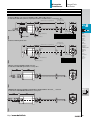
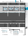
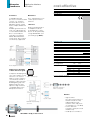
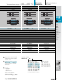
Micropulse
Transducers
B.2
B.4
B.6
B.8
B.10
B.12
B.14
B.16
B.18
Contents
Rod series
General data
Analog interface
Digital
pulse interface
SSD interface
CANopen interface
PROFIBUS-DP
interface
Magnets and
floats
Installation notes
Special series
B
BTL
General
data
Analog
interface
Digital
pulse
inteface
SSD
interface
CANopen
interface
PROFIBUS-DP
interface
Magnets
and
floats
Installation
notes
Special
series
B.1
Micropulse
Transducers
General Data
Rod Series
Pressure rated to 600 bar,
high repeatability,
non-contact, rugged
The BTL Micropulse transducer is the rugged position
feedback system for use
under extreme ambient
conditions measuring
between 25 and 4000 mm.
Shock load
Vibration
Polarity reversal protected
Overvoltage protection
Dielectric strength
Enclosure rating per IEC 60529
Housing material
Mounting
Pressure rating
Connection type
EMC testings:
RF emission
Static electricity (ESD)
Electromagnetic fields (RFI)
Fast transients (BURST)
Line-carried noise,
induced by high-frequency fields
Standard nominal strokes [mm]
▼
The actual waveguide is
protected inside a highpressure resistant stainless
steel tube. The system
is ideal for use in hydraulic
cylinders for position
feedback or as a level
monitor with aggressive
media in the food and
chemical industries.
Series
B.2
BTL5 Rod-style
100 g/6 ms per IEC 60068-2-27
12 g, 10...2000 Hz per IEC 60068-2-6
yes
Transzorb protection diodes
500 V (GND to housing)
IP 67 (when BKS-S... IP 67 connector is in place)
Anodized aluminum/1.4571 stainless tube,
1.3952 stainless investment cast flange
thread M18×1,5, 3/4"-16UNF on request
600 bar installed in hydraulic cylinder
connector or integral cable
EN 55011 Group 1, Class A
IEC 61000-4-2 Severity Level 3
IEC 61000-4-3 Severity Level 3
IEC 61000-4-4 Severity Level 4
IEC 61000-4-6 Severity Level 3
0025, 0050, 0075, 0100, 0125, 0150, 0175, 0200,
0225, 0250, 0275, 0300, 0325, 0350, 0375, 0400,
0425, 0450, 0475, 0500, 0550, 0600, 0650, 0700,
0750, 0800, 0850, 0900, 0950, 1000, 1100, 1200,
1300, 1400, 1500, 1600, 1700, 1800, 1900, 2000,
2250, 2500, 2750, 3000, 3250, 3500, 3750, 3850,
4000 or in 5-mm increments on request
Included
– Transducer (select your interface starting
page B.4)
– Jam nuts M18×1.5
– User's manual
Please order separately:
Magnets page B.14
Floats page B.15
Connectors starting page BKS.3
Micropulse
Transducers
Series
General Data
Rod Series
BTL5 Rod-style
Transducer, Magnet, S 32 connector with BKS-S 32M-_ /BKS-S 33M connector
for transducers with analog interface, digital pulse interface and SSD interface, see Page B.4...B.9
Nominal stroke = measuring area
Damping zone
(non-usable area)
B
BTL
Magnet
BKS-S 32M-_
Thread
M4×4/6 deep
Thread M18x1,5
BKS-S 33M
Mounting surface
Interface
Analog
A, E, C, G
Digital
P, M, I
SSD
S
A (mm)
74
57
74
B (mm)
69
69
69
C (mm)
48
48
48
General
data
Analog
interface
Digital
pulse
inteface
Transducer with integrated cable
Nominal stroke = measuring area
SSD
interface
Damping zone
(non-usable area)
CANopen
interface
PROFIBUS-DP
interface
Magnet
Magnets
and
floats
Thread
M4×4/6 deep
Thread M18x1.5
Mounting surface
Interface
Analog
A, E, C, G
Digital
P, M, I
SSD
S
Installation
notes
A (mm)
74
57
74
Special
series
CANopen, S 92 plug with BKS-S 92-00 connector
for transducers with CANopen interface see Page B.10
PROFIBUS-DP, S103 plug with BKS-S 103-00, BKS-S 105-00 and BKS-S 48-15-CP-_ _ connector
for transducers with PROFIBUS-DP interface see Page B.12
BKS
Page BKS.3
http://www.balluff.de
B.3
Micropulse
Transducers
Analog interface
Rod series
Series
Output signal
Transducer interface
Input interface
100 % Null- and endpoint
calibration
Null and endpoint of the
analog signal can be buttonset to the desired position.
Depending on the
application, teach-in or
adjust mode is used,
selectable by pressing a
button combination.
Calibration device 115379
BTL5-A-EH01
Procedure for teach-in,
rising signal
before
after
Button inactive
1. Place magnet in new null
position.
Output voltage
Output current
Load current
Max. ripple
Load resistance
System resolution
Button active
Teach-in
Adjust
Store new null value
Null
point
End
point
Null
point
End
point
Ordering code
2. Place magnet at new end
position.
Select calibration method
Hysteresis
Repeatability
Internal sampling frequency
max. non-linearity
Temperature coefficient
Teach-in
Store new end value
3. Newly set measuring area
Pin assignments
Output signals
Adjust
Here you can adjust to a
new start and end value.
This may be required when
you cannot physically move
the magnet to the standard
null and/or end point.
Move the magnet to the new
start and end position, and
adjust the displayed value by
pressing the button until the
desired output values are
reached.
B.4
Operating voltage
Current draw
Polarity reversal protected
Overvoltage protection
Dielectric constant
Operating temperature
Storage temperature
Features of Micropulse
BTL5-A/C/E/G...B
– 100 % adjustment of
analog signal
– 3 calibration modes:
Teach-in, adjustment for
null and end point, and
online setting
– Electronics head can be
replaced if needed
– Short housing
– Error signal:
No magnet in measuring
area,
transducer in calibration
mode
Pin
1
2
3
5
Operating voltage
6
7
8
Connect shield to housing.
Online setting
This programming function
allows you to set the null
and end point while in run
mode, such as in a closed
loop configuration. During
the calibration procedure
no error signal is output, so
that no uncontrolled
movement of the hydraulics
can occur.
The calibration range is
limited to ± 12.5 %.
▼
Used for changing the
factory set null and end point
with a new null and end
point. First the magnet must
be brought to the new null
point and then to the new
end position, and the
respective values stored by
pressing the button.
Voltage output
Current output
Color
YE
GY
PK
GN
BU
BN
WH
Included:
– Transducer
– Jam nut
– Calibration device 112774
– User's guide
Please order separately:
Magnets page B.14
Connectors
starting page BKS.3
100 % stroke adjustment
BTL5 Rod
analog
A
analog
BTL5 Rod
analog
E
analog
Micropulse
Transducers
Analog interface
Rod series
BTL5 Rod
analog
C
analog
BTL5 Rod
analog
G
analog
B
BTL
General
data
Analog
interface
BTL5-A11-M_ _ _ _-B-_ _ _ _
BTL5-E1_-M_ _ _ _-B-_ _ _ _
BTL5-C1_-M_ _ _ _-B-_ _ _ _
0...10 V and 10...0 V
–10...10 V and 10...–10 V
4...20 mA or 20...4 mA
max. 5 mA
≤ 5 mV
≤ 0.33 mV
BTL5-G11-M_ _ _ _-B-_ _ _ _
≤ 500 Ohms
≤ 0.66 µA
0...20 mA or 20...0 mA
max. 5 mA
≤ 5 mV
≤ 500 Ohms
≤ 0.66 µA
≤ 0.33 mV
≤ 5 µm
System resolution/min. 2 µm
fSTANDARD = 2 kHz
±100 µm to 500 mm nominal stroke
±0.02 % 500...4000 mm nominal stroke
[150 µV/°C + (5 ppm/°C × P × U/L)] × ∆T
[0.6 µA/°C + (10 ppm/°C × P × I/L)] × ∆T
24 V DC ±20 %
≤ 150 mA
yes
Transzorb protection diodes
500 V (Ground to housing)
–40...+85 °C
–40...+100 °C
BTL5-A11...
▼
Please enter code for output
signal, nominal stroke and
connection type in ordering
code!
▼
0 V Output
10...0 V
0...10 V
GND
+24 V DC
(GND)
Preferred models
Interfaces A11 and E10
BTL5-A11-M_ _ _ _-B-S 32,
BTL5-E10-M_ _ _ _-B-S 32
marked in blue are available
from stock.
http://www.balluff.de
BTL5-E10...
BTL5-E17...
4...20 mA
20...4 mA
0 V Output
BTL5-C10...
BTL5-C17...
0...20 mA
20...0 mA
0 V Output
GND
+24 V DC
(GND)
GND
+24 V DC
(GND)
1
0
7
rising
and falling
(for A and G)
rising
falling
(for C and E)
SSD
interface
CANopen
interface
PROFIBUS-DP
interface
Magnets
and
floats
Installation
notes
Special
series
BTL5-G11...
0 V Output
10...–10 V
–10 ... 10V
GND
+24 V DC
(GND)
Ordering example:
BTL5-E1_-M_ _ _ _-B-_ _ _ _
Output
signal
Digital
pulse
inteface
BKS
Page BKS.3
Standard
nominal strokes [mm]
0025, 0050, 0075, 0100, 0125,
0150, 0175, 0200, 0225, 0250,
0275, 0300, 0325, 0350, 0375,
0400, 0425, 0450, 0475, 0500,
0550, 0600, 0650, 0700, 0750,
0800, 0850, 0900, 0950, 1000,
1100, 1200, 1300, 1400, 1500,
1600, 1700, 1800, 1900, 2000,
2250, 2500, 2750, 3000, 3250,
3500, 3750, 3850, 4000 or in
5-mm increments on request.
Connection type
S 32
KA02
KA05
KA10
KA15
Connector
PUR cable
PUR cable
PUR cable
PUR cable
2m
5m
10 m
15 m
B.5
Micropulse
Transducers
Digital pulse interface
Rod series
cost-effective
Series
Transducer interface
Input interface
P-Interface
M-Interface
Compatible with BTA
processors and various OEM
controls, e. g., Siemens,
Schleicher, B & R, Bosch,
Mitsubishi, Schiele, Parker,
Esitron, Philips, WAGO and
others.
Reliable signal transmission,
even over cable lengths up
to 500 m between BTA and
BTL, is assured by the
especially noise-immune
RS485 differential drivers
and receivers. Noise signals
are effectively suppressed.
The I- and M-interfaces are
control-specific interface
variations.
I-Interface
Used for parallel operation
of multiple transducers,
for example up to 4 transducers can be operated by
a single BTA-M/PMT card
(see starting Page BTA.2).
Ordering code
System resolution
Repeatability
Resolution
Hysteresis
Internal sampling frequency
max. non-linearity
Temperature coefficient of overall system
Operating voltage
Current draw
Operating temperature
Storage temperature
Pin assignments
In-/Output signals
Block diagram for P-interface
Highly precise digitizing
of the P-interface signal
Input
Output
Input
Output
Operating voltage
Companies developing their
own control and processing
44QFP digitizing chip
electronics can create a
highly accurate P-interface
cost effectively and with a
minimum of effort using the
Osz.
5V
Balluff digitizing chip. The
digitizing chip was developed as a high-resolution,
configurable ASIC for the
Micropulse P-interface.
4/8
Bit-BUS
Pin
1
2
3
5
6
7
8
Color
YE
GY
PK
GN
BU
BN
WH
Connect shield to housing.
Micropulse transducer
with 1 to 4 magnets
INIT
Benefits
CPUcontroller
P-pulse output
Controller or processing
electronics
ASIC INFO: +49 (0) 71 58/1 73-2 41
B.6
– High resolution:
the 1 µm actual resolution of
the BTL transducer is fully
supported by the 5 µm
resolution of the chip (at low
clock frequency 2 or 20 MHz)
– Position data from
4 magnets can be processed
simultaneously
– 4/8-bit processor interface
Temperature range
–40...+85 °C
Micropulse
Transducers
Digital pulse interface
Rod series
BTL5 Rod
BTL5 Rod
BTL5 Rod
Pulse P
Pulse P
Impuls M
Impuls M
Pulse I
Pulse I
B
BTL
General
data
Analog
interface
BTL5-P1-M_ _ _ _-B-_ _ _ _
BTL5-M1-M_ _ _ _-B-_ _ _ _
BTL5-I1-M_ _ _ _-B-_ _ _ _
SSD
interface
processing-dependent
2 µm or ±1 digit depending on processing electronics
≤ 2 µm
≤ 4 µm
fSTANDARD = 1 kHz = ≤ 1400 mm
±100 µm to 500 mm nominal stroke
±0.02 % 500...3850 mm nominal stroke
(6 µm +5 ppm × L)/°C
24 V DC ±20 %
≤ 100 mA
–40...+85 °C
–40...+100 °C
▼
Preferred P-interface models
BTL5-P1-M_ _ _ _-B-S 32
marked in blue are available
from stock.
▼
Please enter code for nominal
stroke and connection type in
ordering code!
▼
BTL5-P1-M...
INIT
START/STOP
INIT
START/STOP
GND
+24 V DC
(GND)
Included:
– Transducer
– Jam nut
– User's manual
Digital
pulse
inteface
CANopen
interface
PROFIBUS-DP
interface
Magnets
and
floats
Installation
notes
Special
series
BTL5-M1-M...
INIT
START/STOP
INIT
START/STOP
GND
+24 V DC
(GND)
BTL5-I1-M...
INIT
START/STOP
INIT
START/STOP
GND
+24 V DC
(GND)
Ordering example:
BTL5-P1-M_ _ _ _-B-_ _ _ _
Standard
nominal strokes [mm]
0025, 0050, 0075, 0100, 0125,
0150, 0175, 0200, 0225, 0250,
0275, 0300, 0325, 0350, 0375,
0400, 0425, 0450, 0475, 0500,
0550, 0600, 0650, 0700, 0750,
0800, 0850, 0900, 0950, 1000,
1100, 1200, 1300, 1400, 1500,
1600, 1700, 1800, 1900, 2000,
2250, 2500, 2750, 3000, 3250,
3500, 3750, 3850, 4000 or
in 5 mm increments on request.
Connection type
S 32
KA02
KA05
KA10
KA15
Connector
PUR cable
PUR cable
PUR cable
PUR cable
2m
5m
10 m
15 m
BKS
Page BKS.3
BTA
Page BTA.3
Please order separately:
Magnets page B.14
Connectors starting page BKS.3
http://www.balluff.de
B.7
Micropulse
Transducers
SSD interface
Rod series
SSD Interface
Synchronous serial data
transmission for controls
made by Siemens,
Schleicher, B & R, PEES,
Schiele, Parker, Esitron etc.
as well as for Balluff
BDD-AM 10-...-1-SSD and
BDD-CC 08-1-SSD display/
controllers.
Reliable signal transmission,
even over cable lengths of
up to 400 m between control
and BTL transducer is
assured by especially
noise-immune RS485/422
differential line drivers and
receivers. Any noise signals
are effectively suppressed.
Transducer
BTL5-S1...
BTL5-S1... with processor/controller, wiring example
Clock frequency
depends on cable length
Cable length
< 25 m
< 50 m
< 100 m
< 200 m
< 400 m
Clock freq.
< 1000 kHz
< 500 kHz
< 400 kHz
< 200 kHz
< 100 kHz
Super-fast 2 kHz Sampling rate
B.8
Processor
or
controller
super linear
Series
Output signal
Transducer interface
Input interface
Micropulse
Transducers
SSD interface
Rod series
BTL5 Rod
synchronous serial
S
synchronous serial
B
BTL
Clock sequence
General
data
Analog
interface
Ordering code
BTL5-S1_ _-M_ _ _ _-B-S 32
±1 digit
1, 5, 10, 20 or 40 µm
≤ 1 digit
fSTANDARD = 2 kHz
±30 µm at 5 und 10 µm resolution or ≤ ±2 LSB
(6 µm +5 ppm × L) /°C
24 V DC ±20 %
≤ 80 mA
–40...+85 °C
–40...+100 °C
Repeatability
System resolution depends on version (LSB)
Hysteresis
Internal sampling frequency
max. non-linearity
Temperature coefficient of overall system
Operating voltage
Current draw
Operating temperature
Storage temperature
Pin assignments
Control and
data signals
▼
Supply
voltage (external)
Digital
pulse
inteface
Pin
1
2
3
5
6
7
8
Color
YE
GY
PK
GN
BU
BN
WH
SSD
interface
CANopen
interface
PROFIBUS-DP
interface
Magnets
and
floats
Installation
notes
Special
series
+Clk
+Data
–Clk
–Data
GND
+24 V DC
must remain unconnected
Please enter code for coding, system resolution,
nominal stroke and connection type in ordering code!
Ordering example:
BTL5-S1_ _-M_ _ _ _-B-_ _ _ _
Coding
▼
0
1
6
7
Binary code rising (24 bits)
Gray code rising (24 bits)
Binary code rising (25 bits)
Gray code rising (25 bits)
Included:
– Transducer
– User's guide
Please order separately:
Magnets page B.14
Floats page B.15
Connectors starting page BKS.3
http://www.balluff.de
System
Resolution
1
2
3
4
5
1
5
10
20
40
µm
µm
µm
µm
µm
Standard
nominal strokes [mm]
0025, 0050, 0075, 0100,
0125, 0150, 0175, 0200,
0225, 0250, 0275, 0300,
0325, 0350, 0375, 0400,
0425, 0450, 0475, 0500,
0550, 0600, 0650, 0700,
0750, 0800, 0850, 0900,
0950, 1000, 1100, 1200,
1300, 1400, 1500, 1600,
1700, 1800, 1900, 2000,
2250, 2500, 2750, 3000,
3250, 3500, 3750, 3850,
4000 or in 5 mm
increments on request.
Connection type
S 32
KA02
KA05
KA10
KA15
Connector
PUR cable
PUR cable
PUR cable
PUR cable
2m
5m
10 m
15 m
BKS
Page BKS.3
B.9
Micropulse
Transducers
CANopen interface
Rod series
CANopen Draft Standard 406 (Encoder Profile)
CANopen interface
Based on CAN
(ISO/IEC 7498 and
DIN ISO 11898), CANopen
provides a Layer-7
implementation for industrial
CAN networks. The serial
data protocol of the CAN
specification is defined
according to the producerconsumer principle as
opposed to most other
fieldbus protocols. This
eliminates target addressing
of the process data. Each
bus station decides for itself
how the received data are
processed.
The CANopen interface of
the Micropulse transducer is
compatible with CANopen
conforming with CiA Standard DS301 Rev. 3.0, and
with CAL and Layer 2 CAN
networks.
CAN-BUS features
– Line topology, star
structure also possible
using repeaters
– Cost-effective 2-wire
cabling
– Fast response times, high
data integrity using CRC,
hamming distance of 6
– Potential-free data
transmission (RS485)
– 1 Mbps at cable lengths
< 25 m
– Number of stations
protocol-limited to 127
CANopen offers a high level
of flexibility with respect to
functionality and data
exchnge. Using a standard
data sheet in the form of an
EDS file it is easy to link the
Micropulse transducers to
any CANopen system.
Process Data Object
(PDO)
Micropulse transducers send
their position information
optionally in one or two
PDOs with 8 bytes of data
each. The contents of the
PDOs is free configurable.
The following information
can be sent:
Synchronisation Object
(SYNC)
Serves as a net-wide trigger
for synchronizing all network
participants. When the
SYNC object is received, all
Micropulse transducers
active on the bus store their
current position and velocity
information and then send it
sequentially to the control.
This assures timesynchronous capture of the
measured values.
– Current magnet position
with resolution in 5 µm
steps
– Current velocity of the
magnet with resolution
selectable in 0.1mm/s
steps
– Current status of the four
freely programmable
cams.
Emergency Object
This object is sent with the
highest priority. This is used
for example for error
messages when cam states
change.
Service Data Object (SDO)
Service Data Objects transmit the parameters for the
transducer configuration.
The transducer configuration
may be carried out on the
bus by the controller, or
offline using a PC with a
configuration tool which runs
under Windows. The
configuration is stored in the
transducer in a non-volatile
memory.
certified
CiA 199911-301v30/11-009
CANopen system structures
R
R
SPS/PC mit
CAN-BUS
interface
Velocity
Position
Simple CANopen-System including position and velocity display
B.10
Position + Velocity
Micropulse
Transducers
Series
Output signal
Transducer interface
Input interface
CANopen interface
Rod series
BTL5 Rod
CANopen
H
CANopen
B
BTL
General
data
Analog
interface
Ordering code
BTL5-H1_ _-M_ _ _ _-B-S 92
CANopen interface
Repeatability
System resolution
Position
configurable
Velocity
Hysteresis
Internal sampling frequency
max. non-linearity
Temperature coefficient of overall system
Operating voltage
Current draw
Operating temperature
Storage temperature
▼
Using the CANopen interface
and cable lengths up to
2500 m, the signal is sent at a
length-dependent baud rate
to the control. The high noise
immunity of the connection is
achieved using differential
drivers and by the data monitoring scheme.
Included:
– Transducer
– Jam nut
– Transducer user's guide
– User's guide for configuration and
CAN linking
Please order separately:
Magnets page B.14
Floats page B.15
Connectors starting page BKS.4
http://www.balluff.de
< 25
1000
< 50
800
< 100
500
< 250
250
Color
WH
BN
BU
GY
GN
▼
Pin
1
2
3
4
5
SSD
interface
potential-free
±1 digit
5 µm increments
0.1 mm/s increments
≤ 1 Digit
fSTANDARD = 1 kHz
±30 µm at 5 µm resolution
(6 µm +5 ppm × L)/°C
24 V DC ±20 %
≤ 100 mA
–40...+85 °C
–40...+100 °C
Cable length [m] per CiA DS301
Baud rate [kBaud] per CiA DS301
Pin assignments
Control and
data signals
Digital
pulse
inteface
< 500 < 1000 < 1250
125
100
50
CANopen
interface
PROFIBUS-DP
interface
Magnets
and
floats
Installation
notes
Special
series
< 2500
20/10
CAN_GND
+24 V
0 V (GND)
CAN_HIGH
CAN_LOW
Please enter code for software configuration, baud rate and
nominal stroke when ordering! Cable upon request.
Ordering example:
BTL5-H1_ _-M_ _ _ _-B-S 92
Software
configuration
1
2
3
1
1
2
2
4
×
×
×
×
×
Position and
velocity
Position and
velocity
Position
Baud
rate
0
1
2
3
4
5
6
7
8
1
800
500
250
125
100
50
20
10
Standard
nominal strokes [mm]
MBaud
kBaud
kBaud
kBaud
kBaud
kBaud
kBaud
kBaud
kBaud
0025, 0050, 0075, 0100,
0125, 0150, 0175, 0200,
0225, 0250, 0275, 0300,
0325, 0350, 0375, 0400,
0425, 0450, 0475, 0500,
0550, 0600, 0650, 0700,
0750, 0800, 0850, 0900,
0950, 1000, 1100, 1200,
1300, 1400, 1500, 1600,
1700, 1800, 1900, 2000,
2250, 2500, 2750, 3000,
3250, 3500, 3750, 3850,
4000 or in 5 mm
increments on request.
BKS
Page BKS.4
B.11
Micropulse
Transducers
PROFIBUS-DP interface
Rod series
PROFIBUS-DP Standard EN 50170
As the market leading
standard for serial data
transmission for process
automation, PROFIBUS-DP
is the ideal choice for
implementing automation
tasks with cycle times of
> 5 ms.
Data transmission
A PROFIBUS telegram can
contain up to 244 bytes of
user data per telegram and
station. The BTL5-T uses
max. 32 bytes (max. 4
position values and max. 4
velocity values) for process
data transmission. Up to 126
active stations (Address
0...125) can be connected
on PROFIBUS-DP. User data
cannot be sent with station
address 126. This address is
used as the default address
for bus stations that have to
be parameterized by a Class
2 master (for setting the
device address if there are
no mechanical switches
available).
Each PROFIBUS station has
the same priority. Prioritizing
of individual stations is not
intended, but can be done
by the master since the bus
transmission only makes
up a fraction of the process
cycle anyway.
At a transmission rate of
12 Mbps, the transmission
time for an average data
telegram is in the 100 µs
range.
Master
Slave
Process data
There are two types of
possible masters for
PROFIBUS-DP. Master Class
1 carries out the user
data interchange with the
connected slaves. Master
Class 2 is intended for
startup and diagnostic purposes and may be used
to briefly assume control of
a slave.
Once a PROFIBUS master
has received the parameter
set defined for the slave, it is
able to exchange data.
The parameter set consits of
slave parameters and
configuration data. The
parameter data contain the
description of the slave
settings (e.g. resolution of a
position value). The
configuration data describe
the length and structure of
the data telegram.
For security reasons a slave
is allowed to be written with
new output data only by the
master which previously
parameterized and
configured it. Only after the
slave acknowledges both
messages (parameter data
and configuration data) can
it be assumed that the
configuration and function of
the slave are known to the
master.
Under PROFIBUS-DP the
default is for process data to
be sent from the master to
slaves acyclically and for the
slave data to then be
queried. To ensure
synchronization of multiple
devices, the master may use
the SYNC and FREEZE
services.
GSD
(Device Master Data)
The length of the data
exchangeable with a slave is
defined in the Device Master
Data file (GSD) and is
checked by the slave with
the configuration telegram
and confirmed for
correctness.
In modular systems, various
configurations are defined
in the GSD file. Depending
on the desired functionality,
one of these configurations
can be selected by the
user when the system is
configured. The BTL5-T
is a modular device with the
possibility of selecting the
number of magnets (position
values).
Master Class 1
Slave 1
Device address
DIP switch settable
B.12
After a RESET or after power
is restored, the master
attempts to establish contact
with all the parameterized
slaves in order of lowest to
highest address.
PROFIBUS-DP permits
multiple Class 1 and Class 2
masters to be connected
(see illustration below).
Master Class 2
Slave 2
Slave 3
Slave 4
Slave x
Micropulse
Transducers
Position + Velocity
Series
Output signal
Transducer interface
Input interface
PROFIBUS-DP interface
Rod series
BTL5 Rod
PROFIBUS-DP
T
PROFIBUS-DP
B
BTL
General
data
Analog
interface
Ordering code
Connector version S103
Profibus Version
Profibus interface
Repeatability
System resolution
Position
configurable
Velocity
Hysteresis
Internal sampling frequency
max. non-linearity
Temperature coefficient of overall system
Magnet traverse speed
Operating voltage
Current draw
Operating temperature
Storage temperature
GSD file
Address assignment
Cable length [m]
Baud rate [Kbps]
Pin assignments
Control and
data signals
Supply voltage
and shield
Digital
pulse
interface
BTL5-T1_ 0-M_ _ _ _-B-S103
< 100
12000
EN 50170, Encoder
potential-free
±1 digit
5 µm increments (configurable)
0.1 mm/s increments (configurable)
≤ 1 digit
fSTANDARD = 1 kHz
±30 µm at 5 µm resolution
(6 µm + 5 ppm × L)/°C
any
24 V DC ±20 %
≤ 120 mA
–20...+85 °C
–20...+100 °C
BTL504B2.GSD
mechanical switches and Master Class 2
< 200
< 400
< 1000
1500
900
187.5
S103 5-pin
3
2
4
1
Data GND
R×D/T×D-N (A)
R×D/T×D-P (B)
VP +5 V
+24 V
0 V (GND)
Ground PROFIBUS-DP
Shield supply
SSD
interface
CANopen
interface
PROFIBUS-DP
interface
Magnets
and
floats
Installation
Special series
< 1200
93.7/19.2/9.6
S103 3-pin
1
3
5
4
▼
BKS
Please enter code for
software configuration and nominal
stroke in ordering code!
Ordering example:
BTL5-T1_ 0-M_ _ _ _-B-S103
▼
Software
configuration
Included:
– Transducer
– User's guide
Please order separately:
Magnets starting page B.14
Connectors starting page BKS.6
GSD file BTL5TGSD 119399 (free of charge)
http://www.balluff.de
1
2
3
1 magnet
2 magnets
4 magnets
Page BKS.6
Standard
nominal strokes [mm]
0025, 0050, 0075, 0100, 0125,
0150, 0175, 0200, 0225, 0250,
0275, 0300, 0325, 0350, 0375,
0400, 0425, 0450, 0475, 0500,
0550, 0600, 0650, 0700, 0750,
0800, 0850, 0900, 0950, 1000,
1100, 1200, 1300, 1400, 1500,
1600, 1700, 1800, 1900, 2000,
2250, 2500, 2750, 3000, 3250,
3500, 3750, 3850 or in 5 mm
increments on request.
B.13
Micropulse
Transducers
Magnets
Rod series
Magnet
BTL5 Rod
Magnet
BTL5 Rod
Magnet
BTL5 Rod
Magnet
BTL5 Rod
BTL-P-1013-4R
BTL-P-1013-4S
BTL-P-1012-4R
BTL-P-1014-2R
Material
Weight
Magnet traverse speed
Operating temperature/Storage temperature
Al
approx. 12 g
any
–40...+100 °C
Al
approx. 12 g
any
–40...+100 °C
Al
approx. 12 g
any
–40...+100 °C
Al
approx. 10 g
any
–40...+100 °C
Ordering code PA 60 glass fiber reinforced
BTL-P-1013-4R-PA
BTL-P-1012-4R-PA
Material
Weight
Magnet traverse speed
Operating temperature/Storage temperature
PA 60 glass fiber reinforced
approx. 10 g
any
–40...+100 °C
PA 60 glass fiber reinforced
approx. 10 g
any
–40...+100 °C
Description
for series
Ordering code Al
B.14
Micropulse
Transducers
Description
for series
Float
BTL5 Rod
Float
BTL5 Rod
Float
BTL5 Rod
Floats
Rod series
Float
BTL5 Rod
B
BTL
General
data
Analog
interface
Ordering code
Material
Weight
Operating/Storage temperature
Displacement in water
Pressure resistance (static)
BTL2-S-3212-4Z
Stainless 1.4571
approx. 20 g
–40...+120 °C
approx. 35 mm
24 bar
BTL2-S-4414-4Z
Stainless 1.4571
approx. 35 g
–40...+120 °C
approx. 30 mm
20 bar
BTL2-S-6216-8P
Stainless 1.4541
approx. 66 g
–40...+120 °C
approx. 41 mm
15 bar
BTL2-S-5113-4K
Stainless 1.4571
approx. 34 g
–40...+120 °C
approx. 26 mm
40 bar
Digital
pulse
inteface
SSD
interface
CANopen
interface
PROFIBUS-DP
interface
Magnets
and
floats
Installation
notes
Special
series
http://www.balluff.de
B.15
Micropulse
Transducers
Installation notes
Rod series
Application
Hydraulic cylinder with
closed-loop control
Installation in
hydraulic cylinders
B.16
Micropulse
Transducers
Hassle-free service
Cylinder-mounted transducers are often located in
difficult to access spots. If a
transducer is damaged or
fails, replacing the complete
transducer with head and
waveguide is often a difficult
and expensive proposition.
Should a problem occur in
the electronics of the
Installation notes
Rod series
Micropulse transducer, the
electronics head can be
easily and quickly exchanged
for a new one. The fluid
circuit also remains intact,
with no draining necessary.
B
BTL
General
data
Analog
interface
Digital
pulse
inteface
SSD
interface
CANopen
interface
PROFIBUS-DP
interface
Magnets
and
floats
Servicing a vertical installation
Installation
notes
Special
series
Servicing a horizontal installation
Installation
If magnetizable materials are
used, the installation must
be carried out as shown in
the drawing below. Sealing is
at the flange mounting
surface, using the supplied
O-ring 15.4 × 2.1 with the
M18 × 1.5 thread..
The BTL Micropulse
transducer is provided with
an M18 × 1.5 mounting
thread. We recommend
mounting into nonmagnetizable materials.
O-ring groove
Threaded port to
ISO 6149
Magnet
Non-magnetizable spacer
http://www.balluff.de
B.17
Micropulse
Wegaufnehmer Special series
Micropulse
Special series
Difficult applications often
make special demands on
the sensors. Balluff meets
these requirements with
transducers that have been
specified and developed in
conjunction with the systems
integrator. Behind this is a
large, highly motivated
Micropulse development
team as well as Balluff's own
EMC Testing Laboratory and
shock and vibration test
centers.
The "3-in-1" transducer!
– 2- or 3-way redundant
positioning system
for heightened safety
requirements
– One transducer consists
of two or three completely
separate positioning lines
– Start/Stop or analog
interfaces
– Compact housing
Available outputs:
Tilt control on rail cars
– analog 0...10 V,
4...20 mA, 0...20 mA,
–10...10 V
– P-type pulse interface
Propeller pitch control
Rudder control
B.18
Micropulse
Transducers
Special series
B
BTL
General
data
Analog
interface
Mounting
surface
Digital
pulse
inteface
SSD
interface
0...10 V
4...20 mA
0...20 mA
–10...10 V
CANopen
interface
PROFIBUS-DP
interface
Magnets
and
floats
Installation
notes
Special
series
For information call:
+49 (0) 71 58/1 73-0
http://www.balluff.de
B.19
Micropulse
Transducers
B.20
Measure travel
with the highest precision