1
ROVER
USER GUIDE Rev 2.4
This guide is only available in English
Ce manuel est seulement disponible uniquement en Anglais
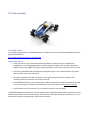
The DFRobotShop Rover is intended to be a “learning platform” which provides users with the hardware to get
started in programming mobile robots using Arduino. The sample code available here can be used as reference
to help you test the various platforms, but users are expected to learn how to use the Arduino software.
Contents
Arduino.............................................................................................................................................................5
Overview...........................................................................................................................................................5
PCB V1.0............................................................................................................................................................6
PCB V1.5............................................................................................................................................................6
PCB V2.0............................................................................................................................................................8
Basic Kit (V1.0, V1.5, V2.0 ).............................................................................................................................10
Assembly Guide...........................................................................................................................................10
Important Notes..........................................................................................................................................10
Power..........................................................................................................................................................10
Motion........................................................................................................................................................11
Specifications (Basic Kit)...............................................................................................................................11
Bluetooth / Xbee Kits (V1.0, V1.5)....................................................................................................................12
Assembly Guide...........................................................................................................................................12
Important Notes..........................................................................................................................................12
Power..........................................................................................................................................................12
Motion........................................................................................................................................................12
Specifications (Basic Kit)...............................................................................................................................13
Bluetooth / Xbee Kits (V2.0).............................................................................................................................14
Assembly Guide...........................................................................................................................................14
Important Notes..........................................................................................................................................14
Power..........................................................................................................................................................14
Motion........................................................................................................................................................15
Specifications (Basic Kit)...............................................................................................................................15
V2.0 Mecanum Kit..........................................................................................................................................16
Assembly Guide...........................................................................................................................................16
Important Notes..........................................................................................................................................16
Motion........................................................................................................................................................17
V2.0 Omniwheel Kits........................................................................................................................................18
Assembly Guide...........................................................................................................................................18
Important Notes..........................................................................................................................................18
Power..........................................................................................................................................................19
Motion ........................................................................................................................................................20
Autonomous Kit...............................................................................................................................................21
Assembly Guide...........................................................................................................................................21
Power..........................................................................................................................................................21
Motion........................................................................................................................................................21
Specifications (Basic Kit)...............................................................................................................................21
Programming...................................................................................................................................................22
Important notes...........................................................................................................................................22
Basic Kit (V2.0).............................................................................................................................................23
Autonomous Kit (V2.0).................................................................................................................................23
Bluetooth Kit (V2.0).....................................................................................................................................24
XBee kit (V2.0).............................................................................................................................................25
Sample Code................................................................................................................................................26
Sketch #1: Basic Rover – Full speed forward..............................................................................................26
Sketch #2: Basic Rover – W/A/S/D Keyboard Control.................................................................................27
Sketch #3: V2.0 Mecanum – Basic Directions............................................................................................28
Sketch #4: Omni Wheel Rover – Basic Directions.......................................................................................30
Sketch #5: Basic Rover V1.0 and V1.5 - Analog Sensors.............................................................................32
Sketch #6: Encoders - Counting.................................................................................................................32
Hyperterminal configuration........................................................................................................................33
Troubleshooting V2..........................................................................................................................................35
FAQ.................................................................................................................................................................43
Power Issues................................................................................................................................................43
Motion / Mechanical Issues.........................................................................................................................43
Programming...............................................................................................................................................44
Versions & Kits.............................................................................................................................................46
Upgrades and Optional Parts........................................................................................................................50
Compatibility...................................................................................................................................................51
Universal Connection Point..........................................................................................................................51
Shield Compatibility.....................................................................................................................................52
Design.........................................................................................................................................................52
Useful Links.....................................................................................................................................................53
Products......................................................................................................................................................53
Software......................................................................................................................................................53
Support.......................................................................................................................................................53
Arduino
“Arduino is an open-source electronics prototyping platform based on flexible, easy-to-use hardware and
software. It's intended for artists, designers, hobbyists, and anyone interested in creating interactive objects or
environments.” - www.arduino.cc
There are many ways to learn how to code in Arduino. We suggest one or more of the following:
•
www.arduino.cc -> “Learning” and “Reference” categories
•
Arduino-related books http://www.robotshop.com/books.html
Overview
This guide contains all information related to the DFRobotShop Rover Series. Rather than releasing multiple
user guides for different versions of the DFRobotShop Rover, this guide distinguishes between versions
whenever necessary.
The DFRobotShop Rover is a versatile mobile robot tank based on the popular Arduino microcontroller. The
basic Rover uses the Tamiya twin motor gearbox but can also be purchased in a variety of kits and
configurations. The DFRobotShop Rover PCB incorporates a standard Arduino (surface mount ATMega328), dual
motor driver (connected to digital pins 5 to 8), onboard voltage regulator and prototyping area. The PCB itself is
partially used in the mechanical structural of the robot. The voltage regulator allows the entire board to be
powered using as little as 3.7V up to ~9V*. Versions 1.5 and up incorporate an onboard 3.7V LiPo charger.
In order to make assembly as easy as possible, wire crimps have been included to give the option of crimping
the wires to the motors (soldering is always preferable if it's an option). The DFRobotShop Rover is compatible
with a variety of shields (when used at the same time as the motor driver) and is compatible with all shields if
the motors are not connected. Additional features common to all versions include pinout for the DFRobot
Bluetooth and DFRobot APC220 RF modules, 6x cool blue LEDs (jumper selectable) placed around the board
and a universal mounting point for Lynxmotion brackets at the front of the board.
*Note that the motors included with the Tamiya Twin Motor Gearbox kit operate at ~3V to 4.5V. 6V motors are
available for purchase separately.
PCB V1.0
The V1.0 PCB is almost identical to V1.5 below except for items (1) and (2). The V1.0 board is not certified RoHS
compliant.
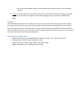
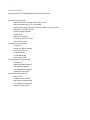
PCB V1.5
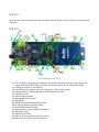
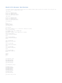
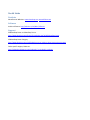
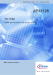
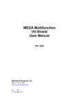
Figure 1: DFRobotShop Rover V1.5 Features
(1) 3.7V LiPo battery charging jumper. Important note: jumper should only be in place when using a LiPo
battery connected to (38), otherwise remove. Do NOT use jumper if you are using the 4xAA pack.
(2) Charging circuit for 3.7V LiPo batteries
(3) Mini USB connector (programming and charging LiPo; cannot power motors)
(4) Voltage regulation circuit (roughly behind USB and barrel connector)6
(5) FTDI USB to serial3
(6) Arduino stacking headers
(7) ATMega328P microcontroller1
(8) Reset button
(9) APC220 RF or DFRobot Bluetooth connector
(10) In-system programming (ICSP) headers
(11) ST L293B Dual motor controller2
(12) Empty space for cargo / solderless breadboard
(13) LED jumper select
(14) Motor On/ Off switch
(15) Mini JST connector (powers board and motors)
(16) Barrel connector (powers board and motors)
(17) Light sensor jumper (connects light sensor to analog pin 0)
(18) Temperature sensor jumper (connects temperature sensor to analog pin 1)
(19) I2C connector
(20) LM35 temperature sensor5
(21) Light sensor4
(22) 4xAA battery holder holes
(23) Universal connection point
*Important note: jumper (1) in figure 1 should only be in place when using a LiPo battery connected to (15),
otherwise remove.
1
Surface mount ATMega328 chip from ATMEL:
http://www.atmel.com/dyn/products/product_card.asp?PN=ATmega328P
2
ST L293B Four Channel H-Bridge Driver (DIP16):
http://www.st.com/stonline/products/literature/ds/1328.pdf
3
FTDI 0947-B USB UART IC:
http://www.ftdichip.com/Products/FT232R.htm
4
Light Sensor (V1.0 and V1.5):
http://us.100y.com.tw/pdf_file/GL5528.pdf
5
Temperature Sensor (V1.0 and V1.5):
http://www.national.com/mpf/LM/LM35.html
6
Voltage regulation:
Voltage: 3.5V (min) to 9V (max) via Vin pin, PWRin (3.5mm jack) or white connector.
The Tamiya motors run at 3 to 4.5V nominal. 6V+ will work but reduce the motor’s life
6V motors are available separately should you want to make your rover faster.
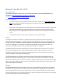
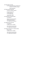
PCB V2.0
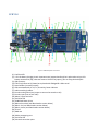
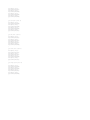
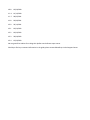
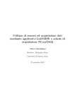
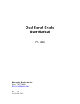
Figure 2: DFRobotShop Rover V2 Features
(1) Cool blue LED
(2) 3.7V LiPo battery charging circuit. Important note: jumper should only be in place when using a LiPo
battery connected to (38), otherwise remove. Do NOT use jumper if you are using the 4xAA pack.
(3) USB connector
(4) FTDI Chip (USB to serial) shown but replaced with ATMega8 for USB to serial
(5) Reset headers (normally unused)
(6) LEDs associated with pin 13, Tx / Rx activity, Power indicator
(7) Arduino stacking headers
(8) Encoder analog select (use jumper to connect the encoder to A1)
(9) Encoder input (one on each side)
(10) Motor 2 input terminals
(11) Cool blue LED
(12) L298P Dual Motor driver
(13) XBee select switch (see XBee headers section below)
(14) XBee 1 slot (see XBee headers section below)
(15) XBee 1 pinout (see XBee headers section below)
(16) 5V row
(17) GND row
(18) Solder prototyping area
(19) Cool blue LED
(20) Universal connection point
(21) 2x slots for additional mounting of sensors
(22) Cool blue LED
(23) Mounting holes for 2nd motor (Mecanum and 4WD versions)
(24) 5V row
(25) GND row
(26) XBee 2 slot (XBee faces the front of the board, towards #20)
(27) XBee 2 pinout (for possible use with the prototyping area)
(28) Cool blue LED
(29) Motor 1 screw terminals
(30) DFRobot Bluetooth / APC220 (RF) input
(31) ICSP headers
(32) Reset button
(33) ATMega329 microchip
(34) Voltage regulator (circuit)
(35) Barrel connector
(36)On / Off switch (On towards the center of the board)
(37) Cool blue LED and main LED jumper (jumper on = 6x LEDs powered at all times)
(38) Mini JST connector for 4xAA battery pack or 3.7V LiPo pack
Xbee Headers
The two XBee slots can be used with both series 1 and series 2 XBee modules. Note that the basic rover does
NOT include the headers which can be purchased separately (they would need to be soldered to the board).
Headers were not included to allow the largest possible flat cargo area on the PCB (to install a solderless
breadboard for example). Certain kits such as the Xbee and Bluetooth kits do include a pair of headers which
must be soldered to the board.
When putting in the Xbee module in place, ensure the XBee modules are oriented correctly before inserting
(with the antenna facing the REAR of the board toward the USB port;). Follow the numbers on the XBee module
and those on the DFRobotShop Rover PCB – they should line up.
When using ONE XBee, use slot marked #26 above (XBee2) to have access to the XBee switch (#13). When
programming the robot, set the switch to xbee1 to free up the Tx and Rx lines. After programming, set the
switch to xbee2 to connect the Tx and Rx lines to the XBee module.
When using TWO XBee modules, we suggest one is connected to the prototyping area, and then connected to
the digital I/O pins using soft serial. When programming the robot, you will likely need to remove the Xbee in
position 14 to get access to the XBee switch.
Basic Kit (V1.0, V1.5, V2.0 )
Assembly Guide
The assembly video guide can be found on RobotShop’s Youtube page (RobotShopTV) at:
V1.0 and V1.5: http://www.youtube.com/watch?v=yXW1yrmKiuI
V2.0: www.youtube.com/watch?v=MWWoEul9Qsk
Important Notes
•
For the basic version (tracks), assemble the Tamiya Twin Motor Gearbox in the Type C configuration
ONLY. Note that Type A and Type B configurations will cause the track to be too tight. Note that some
parts will remain unused.
•
If you use the crimps, the bare motors leads closest to the board can potentially contact the pins on the
underside of the PCB. We highly suggest covering the pins closest to the motor leads with a bit of
electrical tape, and also wrapping the bare leads of the motor with electrical tape (not included with
the kit)
•
Use EITHER the mini JST connector (15) or the Barrel connector (16). NOT BOTH.
Power
1. USB: Connecting a USB cable (sold separately) will power the microcontroller – not the motors. If you
have L1_SEL jumper in place, it will also charge any LiPo battery connected to the white mini JST
connector (15).
2. Barrel: The barrel connector powers both the microcontroller and the motors. To power only the
microcontroller, you need a 3 to 12V adapter capable of ~250mA. To power the motors, you need a 3V
to 6V adapter capable of ~1.5A. Note that if your power supply cannot provide enough power to the
motors, they will not turn. Use EITHER the mini JST connector OR the barrel connector – NOT BOTH.
3. Mini JST: The JST connector can power both the microcontroller and the motors. We suggest using a
3.7V LiPo battery pack of at least 1000mAh or more. The board (microcontroller and motor controller)
will only turn on if you set the On/Off switch to ON. The batteries connect directly to the motors (not
regulated). The mini JST can handle up to ~12V, but keep in mind that the voltage goes directly to
whichever motors are connected.Use EITHER the mini JST connector OR the barrel connector – NOT
BOTH.
a. 4x AA Battery Pack: The DFRobotShop Rover includes a 4xAA battery pack which can be
connected directly to the white power input at the back of the board. Both alkaline (1.5V) and
rechargeable (1.2) batteries can be used, and the batteries power both the board and the
motors. Remove jumper (1) in figure 1 when using the AA battery pack.
b. LiPo battery: A LiPo pack with the correct mini JST connector can be used to power the
DFRobotShop Rover. This has the advantage of significantly reducing the weight of the rover
and also takes advantage of the onboard LiPo charger. You can use a 3.7V or 7.4V LiPo battery,
but note that the onboard charger can only provide 4.3V charge current, so it won't charge a
7.4V LiPo.
4. Vin pin: An Arduino board can be powered using the Vin pin located to the left of the A0 pin. However,
this pin is not connected to a regulator and we do not suggest using it to power the DFRobotShop
Rover.
Motion
The DFRobotShop Rover Basic Kit uses two tank tracks, each connected to their own DC gear motor. Rotating
the tracks at the same time in the same direction produces forward motion. Rotating the tracks at the same
time in the opposite direction causes the robot to move in reverse. Varying the speed of one of the tracks will
cause the robot to move in a circle. Rotating the tracks in opposite directions causes the robot to turn clockwise
(or counter-clockwise) on itself (zero turning radius).
Specifications (Basic Kit)
•
•
•
Maximum speed (using 4x AA NiMH batteries and motor config. 'C'): 12.5cm/sec (no load)
PCB Dimensions: 57mm x 195mm (200mm for V2.0)
Overall dimensions: 200mm long x 108mm wide x 58mm high
Weight (assembled kit not including batteries): 250g
Bluetooth / Xbee Kits (V1.0, V1.5)
Assembly Guide
The assembly video guide for the basic kit can be found on RobotShop’s Youtube page (RobotShopTV) at:
V1.0 and V1.5: http://www.youtube.com/watch?v=yXW1yrmKiuI
V2.0: www.youtube.com/watch?v=MWWoEul9Qsk
Important Notes
•
For the basic version (tracks), assemble the Tamiya Twin Motor Gearbox in the Type C configuration
ONLY. Note that Type A and Type B configurations will cause the track to be too tight. Note that some
parts will remain unused.
•
If you use the crimps, the bare motors leads closest to the board can potentially contact the pins on the
underside of the PCB. We highly suggest covering the pins closest to the motor leads with a bit of
electrical tape, and also wrapping the bare leads of the motor with electrical tape (not included with
the kit)
•
Use EITHER the mini JST connector (15) or the Barrel connector (16). NOT BOTH.
Power
The Bluetooth and Xbee kits include a 3.7V, 1000mAh LiPo battery pack which was chosen because the
standard Tamiya motors operate at ~3V nominal. The board (microcontroller and motor controller) will only
turn on if you set the On/Off switch to ON. The batteries connect directly to the motors (not regulated). The
mini JST can handle up to ~12V, but keep in mind that the voltage goes directly to whichever motors are
connected. Use EITHER the mini JST connector OR the barrel connector – NOT BOTH.
The DFRobotShop Rover Bluetooth and Xbee kits still include a 4xAA battery pack which can be connected
directly to the white power input at the back of the board instead of the LiPo . Both alkaline (1.5V) and
rechargeable (1.2) batteries can be used, and the batteries power both the board and the motors. Remove
jumper (1) in figure 1 when using the AA battery pack.
The DFRobotShop Rover V1.0 Bluetooth and XBee kits (discontinued) included a Seeedstudio charger and
battery which replaced the 4xAA battery pack. In order to use the LiPo battery with the shield, use a spare
piece of wire and connect pins Vin and 5V on the shield. The battery itself should be connected to the JST plug
closest to the 2x3 pin headers (not the one next to the USB plug). To charge the battery, simply plug your USB
cable into the USB port of the shield.
Motion
The DFRobotShop Rover Basic Kit uses two tank tracks, each connected to their own DC gear motor. Rotating
the tracks at the same time in the same direction produces forward motion. Rotating the tracks at the same
time in the opposite direction causes the robot to move in reverse. Varying the speed of one of the tracks will
cause the robot to move in a circle. Rotating the tracks in opposite directions causes the robot to turn clockwise
(or counter-clockwise) on itself (zero turning radius).
Specifications (Basic Kit)
•
•
•
Maximum speed (using 4x AA NiMH batteries and motor config. 'C'): 12.5cm/sec (no load)
PCB Dimensions: 57mm x 195mm (200mm for V2.0)
Overall dimensions: 200mm long x 108mm wide x 58mm high
Weight (assembled kit not including batteries): 250g
Bluetooth / Xbee Kits (V2.0)
Assembly Guide
The assembly video guide for the basic kit can be found on RobotShop’s Youtube page (RobotShopTV) at:
V2.0: www.youtube.com/watch?v=MWWoEul9Qsk
Important Notes
•
For the basic version (tracks), assemble the Tamiya Twin Motor Gearbox in the Type C configuration
ONLY. Note that Type A and Type B configurations will cause the track to be too tight. Note that some
parts will remain unused.
•
If you use the crimps, the bare motors leads closest to the board can potentially contact the pins on the
underside of the PCB. We highly suggest covering the pins closest to the motor leads with a bit of
electrical tape, and also wrapping the bare leads of the motor with electrical tape (not included with
the kit)
•
Use EITHER the mini JST connector (15) or the Barrel connector (16). NOT BOTH.
•
The pair of Xbee headers included in the kit need to be soldered to the board in Xbee slot 2.
•
Bluetoth pairing code is 1234 (used to be 0000). Refer to the Bluetooth module datasheet to be certain.
Power
The Bluetooth and Xbee kits include a 3.7V, 1000mAh LiPo battery pack which was chosen because the
standard Tamiya motors operate at ~3V nominal. The board (microcontroller and motor controller) will only
turn on if you set the On/Off switch to ON. The batteries connect directly to the motors (not regulated). The
mini JST can handle up to ~12V, but keep in mind that the voltage goes directly to whichever motors are
connected. Use EITHER the mini JST connector OR the barrel connector – NOT BOTH.
The DFRobotShop Rover Bluetooth and Xbee kits still include a 4xAA battery pack which can be connected
directly to the white power input at the back of the board instead of the LiPo . Both alkaline (1.5V) and
rechargeable (1.2) batteries can be used, and the batteries power both the board and the motors. Remove
jumper (1) in figure 1 when using the AA battery pack.
Motion
The DFRobotShop Rover Basic Kit uses two tank tracks, each connected to their own DC gear motor. Rotating
the tracks at the same time in the same direction produces forward motion. Rotating the tracks at the same
time in the opposite direction causes the robot to move in reverse. Varying the speed of one of the tracks will
cause the robot to move in a circle. Rotating the tracks in opposite directions causes the robot to turn clockwise
(or counter-clockwise) on itself (zero turning radius).
Specifications (Basic Kit)
•
•
•
•
Maximum speed (using 4x AA NiMH batteries and motor config. 'C'): 12.5cm/sec (no load)
PCB Dimensions: 57mm x 195mm (200mm for V2.0)
Overall dimensions: 200mm long x 108mm wide x 58mm high
Weight (assembled kit not including batteries): 250g
V2.0 Mecanum Kit
Assembly Guide
The assembly video guide for the DFRobotShop Rover 2.0 Mecanum Kit can be found on RobotShop’s Youtube
page (RobotShopTV) at:
http://www.youtube.com/watch?v=UEIFHebyM5s
Important Notes
•
Unlike the basic kit, you can assemble the Tamiya Gearbox in ANY of the three configurations.
Configuration C is still suggested based on overall dimensions and gear ratio in order to provide the
highest traction. We suggest reducing the speed significantly via the motor controller to minimize slip.
•
The frame is mounted under the PCB (but still facing the top) to act as a spacer between the motors
and the solder points under the board.
•
The spacers between the motors and frame are still required to prevent the motor gears from
contacting the barrel connector at the back of the PCB.
•
The DFRobotShop Rover V1.5 and V2.0 boards include an onboard LiPo charger connected to the USB.
If you are not using a LiPo battery connected to the mini JST connector, then remove this jumper.
•
Use EITHER the mini JST connector (15) or the Barrel connector (16). NOT BOTH.
The DFRobotShop Rover Mecanum Kit uses two opposite pairs of Mecanum wheels which need to be correctly
installed on the robot in order to work properly. You can either install them so the outer wheels form an 'X', or
alternatively so that all the wheels point away from one another.
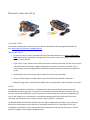
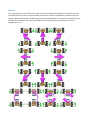
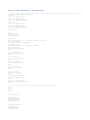
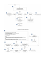
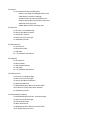
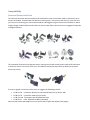
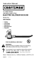
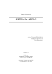
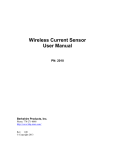
Motion
The image below gives you an idea of the range of motion possible when using Mecanum wheels. Note that
some directions are slower than others because of the forces involved. To facilitate zero radius turning (two
images at bottom right below), consider mounting the Tamiya Gear Motors in the opposite configuration (with
DC motor facing outward). This moves the wheels closer to each other by 8cm when the motors are in
configuration A or B.
V2.0 Omniwheel Kits
The DFRobotShop Rover 2.0 Arduino Compatible Omniwheel Robots use four motors and four omniwheels to
move around. There are multiple variations of the robot, one of which uses 6V DC gear motors with encoders,
compatible with three different types of omniwheels, while the other uses continuous rotation servo motors.
Three sizes of omni wheels are available: 40mm, 48mm and 60mm. All three wheels have adapters for the
DFRobot 6V Gear Motor and for the Hitec 1425CR Continuous Rotation Servo. The 40mm wheel is the least
expensive of the three, but also the slowest. The brackets can be mounted with the motors above or below the
PCB.
Assembly Guide
The assembly video guide for the DFRobotShop Rover 2.0 Omniwheel Kit can be found on RobotShop’s Youtube
page (RobotShopTV) at:
http://www.youtube.com/watch?v=5dP-0V6_ayY
Important Notes
•
There must be sufficient space between the bracket and the PCB – ensure none of the pins on the
bottom of the board contact the metal bracket and if so, use additional spacers.
•
The cables included with the encoder kit DO NOT WORK with the DFRobotShop Rover Motor Controller
Shield directly; you must swap the red and black wires on one end for it to work. If you are not
comfortable doing this, we suggest purchasing 4x RB-Lyn-164.
•
The omni wheel brackets were designed to be mounted to the holes at the far ends of the board so as
to be backward compatible with older versions of the board. They are also compatible with the future
4WD and swerve drive versions of the DFRobotShop Rover.
•
The type of surface the robot travels on will play a very important factor in the robot's speed; only the
48mm omni wheels use rubber outer wheels whereas the 40mm and 60mm omni wheels use plastic
wheels.
Power
The yellow 6V DC gear motor from DFRobot operates at a nominal 6V, but can easily be powered from 4.8V to
7.4V. The higher the voltage, the faster the motor will turn. We suggest using the 7.4V, 2200mAh LiPo battery,
though it’s important to note that the DFRobotShop Rover’s onboard LiPo charger can only charge 3.7V LiPo
batteries. Alternatively, you can use the 4xAA battery pack with 4x reachargeable or 4x Alkaline batteries. The
3.7V LiPo works, but the robot is quite slow.
Continuous Rotation Servo: The Hitec 1425CR is a standard continuous rotation servo meant to be powered at
between 4.8V to 6V. LiPo batteries are therefore NOT suggested. You can use a voltage regulator circuit to
reduce the voltage from 7.4V to 6V, though such a product is not included in any of the kits and must be
purchased separately.
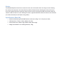
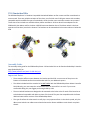
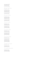
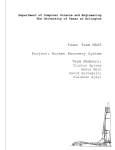
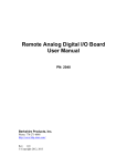
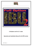
Motion
The image below gives you a sense of the motions possible when using omni directional wheels. Note that
some directions will be slower than others because of the forces involved.
Autonomous Kit
The DFRobotShop Rover Autonomous Kit is intended to help you get started with autonomous control of a
mobile robot which uses sensor feedback. The kit includes the popular “IR compound eye” mounted atop a
simple servo-based pan/tilt system. The eye allows for simple motion tarcking and distance measurement (for
example maze solving and obstacle detection). The kit also includes a buzzer (which can produce simple tones
and auditory feedback) as well as encoders. An IO shield makes for easy connection, and the LiPo battery means
you don't need to invest in AA batteries.
Assembly Guide
•
To assemble the DFRobotShop Rover base, please refer to the assembly video above for the Basic Kit.
•
To assemble the IR compound eye and pan/tilt kit, please use the printed instructions included in the
package.
•
To mount the encoders to the motors, refer to the encoder assembly video.
•
We suggest mounting the buzzer to the upper left or right corner of the tilt bracket using the hardware
provided, leaving only two mounting points for the compound eye.
•
The double-sided tape is suggested to fix the base rotate servo to the PCB, though the DFRobotShop
Rover Expansion Plate (sold separately) is suggested.
•
As is shown in the main image, it is possible to mount the sensor bracket on top of the base rotate
servo, followed by the tilt bracket. Only two out of the four screws can be used. Be careful of the
wiring.
•
The ribbon cable provided is to connect the IR compound eye as well as the Ultrasonic sensor to the IO
shield. The wires are intended to be separated.
Power
The Autonomous kit includes a rechargeable 3.7V 1000mAh LiPo battery. To charge the battery, ensure the
Li_Sel jumper located in position 2 on the DFRobotShop Rover PCB is in place, and connect a USB cable from
your computer to the board. Alternatively, you can use the included 4xAA battery pack, though the jumper
needs to be removed.
Motion
The DFRobotShop Rover Basic Kit uses two tank tracks, each connected to their own DC gear motor. Rotating
the tracks at the same time in the same direction produces forward motion. Rotating the tracks at the same
time in the opposite direction causes the robot to move in reverse. Varying the speed of one of the tracks will
cause the robot to move in a circle. Rotating the tracks in opposite directions causes the robot to turn clockwise
(or counter-clockwise) on itself (zero turning radius).
The kit includes a mini pan/tilt kit which can be used to mount the compound eye, the ultrasonic sensor, the
sensor bracket and the buzzer (individually or all together). The base rotate servo can be stuck to the PCB using
the double-sided tape, or usin the expansion plate sold separately.
Specifications (Basic Kit)
•
Maximum speed (using 4x AA NiMH batteries and motor config. 'C'): 12.5cm/sec (no load)
•
•
•
PCB Dimensions: 57mm x 195mm (200mm for V2.0)
Overall dimensions: 200mm long x 108mm wide x 58mm high
Weight (assembled kit not including batteries): 250g
Programming
www.arduino.cc
The “Arduino” software is a relatively easy to use text-based programming language which is ideal for
programming Arduino-compatible boards. This guide is not meant to teach you how to program Arduino. Please
visit the Arduino website for tutorials, or purchase one of many Arduino-related books.
An alternative to Arduino is Modkit www.modk.it. Modkit is an Arduino compatible graphical software interface
which allows you to use graphical blocks to create easy to understand code without all the hassle of syntax. This
guide does not include sample code for ModKit. Please visit the ModKit website for tutorials.
Important notes
1. The DFRobotShop Rover V1.5 is essentially a standard Arduino Duemilanove board while the
DFRobotShop Rover V2.0 is essentially a standard Arduino Uno board. All code and examples found on
www.arduino.cc can be used.
2. Digital pins 5 to 8 are permanently connected to the onboard motor controller on all versions of the
rover. You can use these pins normally only if no motors are connected to the screw terminals. Note
that the motor controller will still be receiving signals.
3. V1.0 and 1.5: Analog pins 0 and 1 are connected to the onboard light and temperature sensors, but can
be disconnected using the jumpers (17) and (18).
4. V2.0: Analog pins 0 and 1 are connected to the optional encoder modules via jumpers (8) on either side
of the board. If you do not plan to use encoders, ensure the jumpers are not in place, freeing up A0 and
A1.
5. V2.0: The board is based on the Arduino Uno; the drivers do NOT install automatically. Please follow the
installation procedure here: http://arduino.cc/en/Guide/HomePage
Basic Kit (V2.0)
The DFRobotShop Rover Basic Kit needs to be connected to the computer in order for an operator to control its
motion. The robot can also be programmed to move autonomously.
1. Connect the USB cable to your computer and upload sample sketch #2 (code section of this manual if).
2. Ensure you know which COM port is associated with the USB Bluetooth dongle on your computer.
3. For Windows users, open Hyperterminal and follow “Hyperterminal Configuration” in this guide.
4. In the hyperterinal serial window, you can type W, A, S, D (and any other key to stop) to move the rover.
Autonomous Kit (V2.0)
The DFRobotShop Rover Autonomous Kit includes a variety of sensors intended to allow users to experiment
with autonomous control with feedback from the environment.
1. Follow the steps above for getting the basic rover operational.
2. Sample code for using a servo motor can be found under “Examples” in the Arduino software.
3. Sample code for the IR Compound Eye for motion tracking (and also use of the buzzer) can be found
under the “Useful Links” tab in the product description, or at the following link. Note that the
adventure robot uses servo motors as opposed to DC gear motors, and also includes additional IR
sensors not present in the Autonomous Kit. Should the Adventure Robot code be uploaded, the motion
and obstacle detection subroutines will not work without modification.
www.robotshop.com/content/ZIP/dagu-adventure-robot-sample-code.zip
4. For the ultrasonic sensor, sample code is also provided under the “Useful links” tab in the product
description, or at the following link:
www.robotshop.com/content/ZIP/demo-code-sen136b5b.zip
5. Encoder sample code can be found in the code section of this manual.
6. Once you have understood and played with the motion code (for example have tried different speeds)
experiment with each sensor one at a time, but don't merge the code yet.
7. We then suggest “sub-kits” such as the DFRobotShop Rover with the ultrasonic sensor for obstacle
avoidance, or the DFRobotShop Rover with the encoders for accurate motion.
8. There is no specific objective of the kit, though it is possible to create code which uses the encoders, IR
compound eye, pan/tilt, buzzer and LEDs for motion tracking, obstacle detection, feedback and
mapping.
Bluetooth Kit (V2.0)
The new DFRobotShop Rover Bluetooth kit no longer includes a USB Bluetoth dongle and assumes your
computer or smartphone already has Bluetooth. If your computer does not have Bluetooth, you can purchase a
USB Bluetooth module for under $10.
1. Follow the steps above for getting the basic rover operational via USB cable.
2. Install the Bluetooth module on the DFRobotShop Rover PCB in position XBEE2. Check the pin
numbers! Most modules will face the REAR of the board (this is not intuitive).
3. Move the Xbee switch to XBee1 (so the serial lines are NOT connected to the Bluetooth module).
4. Connect the USB cable to your computer and upload your sketch (upload the WASD sketch in the code
section of this manual if you are just starting).
5. Once the sketch has finished uploading, disconnect the USB cable and move the Xbee switch to XBee2
(therefore the Tx and Rx pins are connected to the Bluetooth module)
6. Turn the rover ON (after connecting the LiPo battery of course)
7. Open your Bluetooth software (for example, BlueuSoleil) and pair with the module.
8. Ensure you know which COM port is associated with the USB Bluetooth dongle on your computer.
9. For Windows users, open Hyperterminal and follow “Hyperterminal Configuration” in this guide.
10. In the serial window, you can type W, A, S, D (and any other key to stop) to move the rover.
11. If the rover is turned off or loses power, you may need to upload the code once again.
XBee kit (V2.0)
The new DFRobotShop Rover V2 Xbee kit no longer includes an Xbee shield since there are two Xbee slots
provided on the board (note that Xbee headers are sold separately).
1. Follow the steps above for getting the basic rover operational via USB cable.
2. Install the Xbee module on the DFRobotShop Rover PCB in position XBEE2 Check the pin numbers!
Most modules will face the REAR of the board (this is not intuitive).
3. Move the Xbee switch to XBee1 (therefore NOT connected to the Bluetooth module).
4. Connect the USB cable to your computer and upload your sketch (upload the WASD sketch in the code
section of this manual if you are just starting).
5. Once the sketch has finished uploading, disconnect the USB cable and move the Xbee switch to XBee2
(therefore the Tx and Rx pins are connected to the Bluetooth module)
6. Turn the rover ON (after connecting the LiPo battery of course)
7. Connect the other USB to the USB to Xbee breakout board, and connect the USB cable to the breakout
board. The drivers should install automatically.
8. Ensure you know which COM port is associated with the USB to Xbee breakout board on your
computer.
9. For Windows users, open Hyperterminal and follow “Hyperterminal Configuration” in this guide.
10. In the serial window, you can type W, A, S, D (and any other key to stop) to move the rover.
11. If the rover is turned off or loses power, you may need to upload the code once again.
Sample Code
The DFRobotShop Rover is not intended to be a “complete product” which explains all the steps needed to
achieve a specific objective. Instead, the Rover is a platform which provides you with the basic hardware and
basic software to get started in programming mobile robots and Arduino. The code below is not “optimized”
but is intended to get you started.
Sketch #1 operates both motors at full speed. Sketch #2 allows serial commands to be sent to the DFRobotShop
Rover by either a wired (USB) or wireless (Bluetooth, XBee) connection. The keyboard commands are "w", "a",
"s" and "d" for driving forward, turning left, turning right and reversing. The rover will execute the command
until it is told to stop by pressing any other character. The basic kit requires that the USB cable be connected to
the robot while the Xbee and Bluetooth kits allow for wireless control. Ensure you select the correct COM port
and 9600 baud rate. The Baud rate for the Bluetooth module can be 9600 or 115200 depending on the module
– check the manual to be certain. Note that it is likely the two motors are not identical and you will need to
adjust the speed slightly so the robot goes straight. Font size is reduced to allow easy copy / pasting.
Sketch #1: Basic Rover – Full speed forward
/* Copy and
int E1 = 6;
int E2 = 5;
int M1 = 8;
int M2 = 7;
paste the code below into the Arduino software */
//M1 Speed Control
//M2 Speed Control
//M1 Direction Control
//M2 Direction Control
void setup()
{
int i;
for(i=5;i<=8;i++)
pinMode(i, OUTPUT);
Serial.begin(9600);
}
void loop()
{
int leftspeed = 255; //255 is maximum speed
int rightspeed = 255;
analogWrite (E1,255);
digitalWrite(M1,LOW);
analogWrite (E2,255);
digitalWrite(M2,LOW);
delay(100);
}
Sketch #2: Basic Rover – W/A/S/D Keyboard Control
/*To control the
int E1 = 6; //M1
int E2 = 5; //M2
int M1 = 8; //M1
int M2 = 7; //M2
rover, Copy and paste the code below into the Arduino software*/
Speed Control
Speed Control
Direction Control
Direction Control
void setup(void)
{
int i;
for(i=5;i<=8;i++)
pinMode(i, OUTPUT);
Serial.begin(9600);
}
void loop(void)
{
while (Serial.available() < 1) {} // Wait until a character is received
char val = Serial.read();
int leftspeed = 255; //255 is maximum speed
int rightspeed = 255;
switch(val) // Perform an action depending on the command
{
case 'w'://Move Forward
forward (leftspeed,rightspeed);
break;
case 's'://Move Backwards
reverse (leftspeed,rightspeed);
break;
case 'a'://Turn Left
left (leftspeed,rightspeed);
break;
case 'd'://Turn Right
right (leftspeed,rightspeed);
break;
default:
stop();
break;
}
}
void stop(void) //Stop
{
digitalWrite(E1,LOW);
digitalWrite(E2,LOW);
}
void forward(char a,char b)
{
analogWrite (E1,a);
digitalWrite(M1,LOW);
analogWrite (E2,b);
digitalWrite(M2,LOW);
}
void reverse (char a,char b)
{
analogWrite (E1,a);
digitalWrite(M1,HIGH);
analogWrite (E2,b);
digitalWrite(M2,HIGH);
}
void left (char a,char b)
{
analogWrite (E1,a);
digitalWrite(M1,HIGH);
analogWrite (E2,b);
digitalWrite(M2,LOW);
}
void right (char a,char b)
{
analogWrite (E1,a);
digitalWrite(M1,LOW);
analogWrite (E2,b);
digitalWrite(M2,HIGH);
}
Sketch #3: V2.0 Mecanum – Basic Directions
/* To control the Rover, copy and paste the code below into the Arduino software. Ensure the motors are connected to the correct pins. The
code does not factor in encoders at this time*/
//Front motors
int E1 = 3; //M1 Speed Control
int E2 = 11; //M2 Speed Control
int M1 = 12; //M1 Direction Control
int M2 = 13; //M2 Direction Control
//Rear
int E3
int E4
int M3
int M4
motors
= 6; //M1
= 5; //M2
= 8; //M1
= 7; //M2
Speed Control
Speed Control
Direction Control
Direction Control
void setup(void)
{
int i;
for(i=3;i<=13;i++)
pinMode(i, OUTPUT);
Serial.begin(115200);
}
void loop(void)
{
while (Serial.available() < 1) {} // Wait until a character is received
char val = Serial.read();
int leftspeed = 255; //255 is maximum speed
int rightspeed = 255;
switch(val) // Perform an action depending on the command
{
case 'w'://Move Forward
forward (leftspeed,rightspeed);
break;
case 's'://Move Backwards
reverse (leftspeed,rightspeed);
break;
case 'a'://Turn Left
left (leftspeed,rightspeed);
break;
case 'd'://Turn Right
right (leftspeed,rightspeed);
break;
case 'q'://Turn Right
ccw (leftspeed,rightspeed);
break;
case 'e'://Turn Right
cw (leftspeed,rightspeed);
break;
default:
stop();
break;
}
}
void stop(void) //Stop
{
digitalWrite(E1,LOW);
digitalWrite(E2,LOW);
digitalWrite(E3,LOW);
digitalWrite(E4,LOW);
}
void forward(char a,char b)
{
analogWrite (E1,a);
digitalWrite(M1,HIGH);
analogWrite (E2,b);
digitalWrite(M2,LOW);
analogWrite (E3,a);
digitalWrite(M3,LOW);
analogWrite (E4,b);
digitalWrite(M4,LOW);
}
void reverse (char a,char b)
{
analogWrite (E1,a);
digitalWrite(M1,LOW);
analogWrite (E2,b);
digitalWrite(M2,HIGH);
analogWrite (E3,a);
digitalWrite(M3,HIGH);
analogWrite (E4,b);
digitalWrite(M4,HIGH);
}
void ccw (char a,char b)
{
analogWrite (E1,a);
digitalWrite(M1,HIGH);
analogWrite (E2,b);
digitalWrite(M2,HIGH);
analogWrite (E3,a);
digitalWrite(M3,HIGH);
analogWrite (E4,b);
digitalWrite(M4,LOW);
}
void cw (char a,char b)
{
analogWrite (E1,a);
digitalWrite(M1,LOW);
analogWrite (E2,b);
digitalWrite(M2,LOW);
analogWrite (E3,a);
digitalWrite(M3,LOW);
analogWrite (E4,b);
digitalWrite(M4,HIGH);
}
void left (char a,char b)
{
analogWrite (E1,a);
digitalWrite(M1,LOW);
analogWrite (E2,b);
digitalWrite(M2,LOW);
analogWrite (E3,a);
digitalWrite(M3,HIGH);
analogWrite (E4,b);
digitalWrite(M4,LOW);
}
void right (char a,char b)
{
analogWrite (E1,a);
digitalWrite(M1,HIGH);
analogWrite (E2,b);
digitalWrite(M2,HIGH);
analogWrite (E3,a);
digitalWrite(M3,LOW);
analogWrite (E4,b);
digitalWrite(M4,HIGH);
}
Sketch #4: Omni Wheel Rover – Basic Directions
/* To control the Rover, copy and paste the code below into the Arduino software. Ensure the motors are connected to the correct pins. The
code does not factor in encoders at this time*/
//Front motors
int E1 = 10 ; //M1 Speed Control
int E2 = 11; //M2 Speed Control
int M1 = 12; //M1 Direction Control
int M2 = 13; //M2 Direction Control
//Rear
int E3
int E4
int M3
int M4
motors
= 6; //M1
= 5; //M2
= 8; //M1
= 7; //M2
Speed Control
Speed Control
Direction Control
Direction Control
void setup(void)
{
int i;
for(i=3;i<=13;i++)
pinMode(i, OUTPUT);
Serial.begin(115200);
}
void loop(void)
{
while (Serial.available() < 1) {} // Wait until a character is received
char val = Serial.read();
int leftspeed = 255; //255 is maximum speed
int rightspeed = 255;
switch(val) // Perform an action depending on the command
{
case 'w'://Move Forward
forward (leftspeed,rightspeed);
break;
case 's'://Move Backwards
reverse (leftspeed,rightspeed);
break;
case 'a'://Turn Left
left (leftspeed,rightspeed);
break;
case 'd'://Turn Right
right (leftspeed,rightspeed);
break;
case 'q'://rotate ccw
ccw (leftspeed,rightspeed);
break;
case 'e'://rotate cw
cw (leftspeed,rightspeed);
break;
case 'z'://move at 45 degrees
fortyfive (leftspeed,rightspeed);
break;
case 'x'://move at 135 degrees
onethirtyfive (leftspeed,rightspeed);
break;
// to move at 225 and 315, use the 45 degree and 135 degree code but reverse motor direction.
default:
stop();
break;
}
}
void stop(void) //Stop
{
digitalWrite(E1,LOW);
digitalWrite(E2,LOW);
digitalWrite(E3,LOW);
digitalWrite(E4,LOW);
}
void forward(char a,char b)
{
analogWrite (E1,a);
digitalWrite(M1,LOW);
analogWrite (E2,b);
digitalWrite(M2,HIGH);
analogWrite (E3,a);
digitalWrite(M3,LOW);
analogWrite (E4,b);
digitalWrite(M4,HIGH);
}
void reverse (char a,char b)
{
analogWrite (E1,a);
digitalWrite(M1,HIGH);
analogWrite (E2,b);
digitalWrite(M2,LOW);
analogWrite (E3,a);
digitalWrite(M3,HIGH);
analogWrite (E4,b);
digitalWrite(M4,LOW);
}
void ccw (char a,char b)
{
analogWrite (E1,a);
digitalWrite(M1,HIGH);
analogWrite (E2,b);
digitalWrite(M2,HIGH);
analogWrite (E3,a);
digitalWrite(M3,HIGH);
analogWrite (E4,b);
digitalWrite(M4,LOW);
}
void cw (char a,char b)
{
analogWrite (E1,a);
digitalWrite(M1,LOW);
analogWrite (E2,b);
digitalWrite(M2,LOW);
analogWrite (E3,a);
digitalWrite(M3,LOW);
analogWrite (E4,b);
digitalWrite(M4,HIGH);
}
void left (char a,char b)
{
analogWrite (E1,a);
digitalWrite(M1,HIGH);
analogWrite (E2,b);
digitalWrite(M2,HIGH);
analogWrite (E3,a);
digitalWrite(M3,LOW);
analogWrite (E4,b);
digitalWrite(M4,LOW);
}
void right (char a,char b)
{
analogWrite (E1,a);
digitalWrite(M1,LOW);
analogWrite (E2,b);
digitalWrite(M2,LOW);
analogWrite (E3,a);
digitalWrite(M3,HIGH);
analogWrite (E4,b);
digitalWrite(M4,HIGH);
}
void fortyfive (char a,char b)
{
analogWrite (E1,a);
digitalWrite(M1,LOW);
analogWrite (E3,a);
digitalWrite(M3,LOW);
}
void onethirtyfive (char a,char b)
{
analogWrite (E2,b);
digitalWrite(M2,HIGH);
analogWrite (E4,b);
digitalWrite(M4,HIGH);
}
Sketch #5: Basic Rover V1.0 and V1.5 - Analog Sensors
/* To read the onboard light and temperature sensors, run the code below, then open the serial window at 9600 baud. Ensure the two jumpers are in place*/
int LightValue = 0;
int TemperatureValue = 0;
void setup() {
Serial.begin(9600);
}
void loop() {
LightValue = analogRead(A0);
TemperatureValue = analogRead(A1);
Serial.print("Light: ");
Serial.print(LightValue);
Serial.print(" Temperature: ");
Serial.println(TemperatureValue);
delay(100);
}
Sketch #6: Encoders - Counting
/* The code below simply counts the number of changes, so a disc with 8x white sections and 8x cutouts will provide a count of 16 per 360 degree rotation. It is up to you to integrate it with
your code*/
int rawsensorValue = 0; // variable to store the value coming from the sensor
int sensorcount0 = 0;
int sensorcount1 = 0;
long count = 0;
void setup() {
int i;
for(i=5;i<=8;i++)
pinMode(i, OUTPUT);
Serial.begin(9600);
int leftspeed = 255; //255 is maximum speed
int rightspeed = 255;
}
void loop() {
analogWrite (10,255);
digitalWrite(12,LOW);
analogWrite (11,255);
digitalWrite(13,LOW);
delay(20);
rawsensorValue = analogRead(0);
if (rawsensorValue < 600){ //Min value is 400 and max value is 800, so state chance can be done at 600.
sensorcount1 = 1;
}
else {
sensorcount1 = 0;
}
if (sensorcount1 != sensorcount0){
count ++;
}
sensorcount0 = sensorcount1;
Serial.println(count);
}
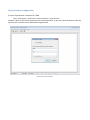
Hyperterminal configuration
To access Hyperterminal in Windows XP / 2000:
Start > All Programs > Accessories > Communications > HyperTerminal
Windows 7 does not come with Hyperterminal as a standard feature, so you must find an alternative. Note that
hypertrm.exe is available online and emulates Hyperterminal.
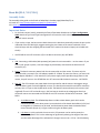
Hyperterminal screen in Windows
Choose the correct COM port associated with the Rover or the XB/BT board
The name “DFRobotShop Rover” is not necessary; you can name it whatever you want.
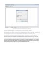
Specify the COM port (USB) that is connected to the DFRobotShop Rover. If you are using XBee, Bluetooth or RF,
select the COM port connected to the Bluetooth dongle / XBee breakout / RF Transmitter (USB).
No configuration is needed for the DFRobot Bluetooth Module – simply connect to it via your Bluetooth
application and the module installed on the DFRobotShop Rover will be picked up (assuming it is powered).
To use the XBee modules, install one on the USB to XBee breakout board in the same orientation as indicated
on the board, and connect the board via USB to your computer. The board should be picked up as a standard
COM port. Install the other XBee module on the XBee shield and install the shield on the board ensuring the
Tx/Rx pins of the shield line up with Rx/Tx pins on the DFRobotShop Rover PCB.
More information about the XBee shield can be found on www.arduino.cc.
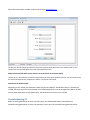
The Bits per second should correspond to the Serial communication Baud rate in the Arduino code. In the
sample code, we selected 9600. Flow control Xon/Xoff works best.
Make sure the On/Off switch on the robot is set to ON (closer to the power input).
Use the W, A, S, D and X keys to move the robot. Note that if you purchased the basic kit, you will need to have
the robot connected to the computer via USB for it to receive commands.
Special note for Bluetooth Kit:
Depending on the module, the bluetooth module may be set to 9600 or 115200 baud, 8 bits. If the default is
115200, the baud rate in the code uploaded to the DFRobotShop Rover must be changed from 9600 to 115200
and correspondingly when using hyperterminal, the baud rate must also be set to 115200.
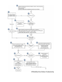
Troubleshooting V2
Before contacting RobotShop to report a problem with your DFRobotShop Rover, please follow the
troubleshooting guide below, and pay close attention to each step. This troubleshooting guide will evolve.
When you come to a step indicating “contact RobotShop”, or “request RMA” please indicate the version of the
Troubleshooting guide (V2 above), as well as the step number. For example, you follow the guide below and
reach step 17 “Request RMA”. Please contact us via the RobotShop Support Center and indicate:
Subject: DFRobotShop Rover Troubleshooting V2, Step 17
If you can provide any additional information about what happened or any steps you took which were not
outlined in the guide, please include them. Be sure to contact RobotShop before the warranty runs out.
FAQ
Power Issues
Q. The batteries fall out of the holder, what can I do (V1.0 and V1.5)?
If you do not plan to use the top of the PCB, you can mount the battery holder to the top rather than the
bottom of the board. Another option is to use a low-cost LiPo pack (~$10).
Q. The battery holder provides intermittent or no power, what should I do (V1.0 and V1.5)?
If you have an old AA battery holder, you can rotate the batteries or push them in so they are tight. Check to
see if there is a small gap between the AA closest to the wires and if so, put a small piece of conductive material
(such as aluminum foil).
Ensure the batteries are
Q. The board does not seem to be getting enough power, or shuts off quickly, what should I do?
Check that the batteries are charged.
Check the default code and ensure it works via USB
Q. One of the 6x blue LEDs around the board does not light up.
Contact RobotShop via the Support Center and we will issue an RMA to have the board exchanged at no charge
to you (assuming it is under warranty)
Motion / Mechanical Issues
Q. The robot moves in an arc when I give both motors the same speed value, how can I correct this?
The motors are likely not identical. To get the robot to move as straight as possible, progressively lower one of
the speed values for the faster motor until it goes in a straight line. It is also important to check that the motor
shafts and sprockets are equally spaced after assembly (you can use the frame as visual reference) and that the
set screws are properly tightened.
Encoder modules will soon be available for the rover which allow you to count how many steps each motor has
rotated. Knowing how each step translates to linear displacement, you can ensure the robot moves in straight
lines and the movements are repeatable.
Q. The motors are noisy, how can I make them quieter?
Use the grease included with the Tamiya dual gearbox and add capacitors to the motors.
http://www.robotshop.com/PDF/motor-noise-reduction.pdf
You can also cover the top and bottom of the gear box with tape.
Q. The drive wheels fall off the motor shaft, what can I do?
Rough up the shaft with some sandpaper and add a dab of glue inside the sprocket bore (hole) before pressing
it onto the shaft.
Q. Are there any other configurations for the tracks or motor?
We have not tested any other configurations (shorter track length, use different hubs/ sprockets in different
locations etc.) though you are free to try. Ensure the tracks are not overly tight so the motors can turn freely.
Q. One of the LEDs arrived broken – what can I do?
If it arrived broken, RobotShop will exchange the PCB at our cost. Please contact us for an RMA.
Q. Is the DFRobotShop Rover edible?
This was not included in our testing
Programming
Q. Where can I find additional sample code for the board?
The board is directly compatible with Arduino Software available for download via www.Arduino.cc Take note
that four of the pins are used for the H-bridge (pins 5, 6, 7, 8). Additional tutorials and sample code are
available via www.arduino.cc
Q. Can I use other software to program the board?
Yes, though you may need to change the bootloader; this is done via the ICSP headers. The most common
alternative software is C / C#.
Q. Can I do a quick motor test?
Copy/paste the following code into Arduino to run the motors continuously at full speed:
/* Copy and paste the code below into the Arduino software */
void setup(void)
{
int i;
for(i=5;i<=8;i++)
pinMode(i, OUTPUT);
Serial.begin(9600);
}
void loop(void)
{
int leftspeed = 255; //255 is maximum speed
int rightspeed = 255;
analogWrite (6,255);
digitalWrite(8,LOW);
analogWrite (5,255);
digitalWrite(7,LOW);
delay(100);
}
Q. Can I operate the 6x cool blue LEDs from the software?
Yes and no: the six LEDs are all connected to one another and therefore cannot be operated independently. This
having been said, a digital pin can be connected to jumper 13 (figure 1) and the other pin header to GND on the
Arduino. Ensure you have the right orientation.
Q. Is there sample code for the 2.0 Mecanum or 2.0 Omni using all four encoders?
Not at this time.
Q. Is there sample code for the Autonomous kit using all sensors at once?
Sort of. The Autonomous kit uses the Compound Eye, which is also used in the Adventure Robot from Dagu.
There is sample code for the Adventure Robot, but it needs to be modified slightly since the DFRobotShop
Rover uses DC gear motors rather than servo motors for propulstion, and an ultrasonic sensor rather than IR
sensors for obstacle avoidance.
Versions & Kits
Several versions of the DFRobotShop Rover have been released:
V1.0 Board (discontinued)
Arduino Duemilanove Design w/FTDI USB to Serial
LEDs connected to pin 13, Tx, Rx and PWR
Temperature and Light sensors connected to A0 and A1 (via jumpers)
DFRobot BT / APC220 Interface
Onboard voltage regulator
On/Off switch
L298 motor Controller
2x Screw terminals for motors
Blank area for cargo
V1.0 Basic Kit (discontinued)
V1.0 Board
Tamiya Twin Motor Gearbox
Tamiya Tank Track Kit
2x Metal Brackets
V1.0 Hardware Bag
4xAA battery holder
V1.0 Bluetooth Kit (discontinued)
V1.0 Basic Kit
DFRobot Bluetooth Module
USB Bluetooth Module
3.7V, 1000mAH LiPo battery
Seeedstudio LiPo shield
V1.0 XBee Kit (discontinued)
Basic V1.0 Kit
2x XBee series 1 modules
USB to XBee breakout board
3.7V, 1000mAH LiPo battery
Seeedstudio LiPo shield
V1.5 Board (discontinued)
V1.0 board with following modifications:
Onboard LiPo battery charger
RoHS compliance
V1.5 Basic Kit (discontinued)
Tamiya Twin Motor Gearbox
Tamiya Tank Track Kit
2x Metal Brackets
V1.0 Hardware Bag
4xAA battery holder
V1.5 Bluetooth Kit (discontinued)
V1.5 Basic Kit
DFRobot Bluetooth Module
USB Bluetooth Module
3.7V, 1000mAH LiPo battery
V1.5 XBee Kit (discontinued)
V1.5 Basic Kit
2x XBee series 1 modules
USB to XBee breakout board
3.7V, 1000mAH LiPo battery
V1.5 Speech Recognition Kit (discontinued)
Basic V1.5 Kit
2x XBee series 1 modules
USB to XBee breakout board
3.7V, 1000mAH LiPo battery
V2.0 Board
V1.5 board with following modifications:
Arduino Uno design w/ ATMega8 USB to serial
L298P Motor Controller & redesign
2x XBee headers w/ switch & Breakout pins
Solder prototyping area (previously cargo area)
Additional mounting holes
Added additional front mounting slots
V2.0 Basic Kit
1x V2.0 PCB + 1x Hardware Bag
1x Tamiya Twin Motor Gearbox
1x Tamiya Tank Track Kit
2x Rover frame (left and right)
1x 4xAA battery holder
V2.0 Bluetooth Kit
1x V2.0 Basic Kit
1x Bluetooth module
1x USB cable
1x 3.7V, 1000mAH LiPo battery
V2.0 XBee Kit
1x V2.0 Basic Kit
2x Xbee modules
1x USB to Xbee breakout
1x USB cable
1x 3.7V, 1000mAH LiPo battery
V2.0 Mecanum Kit
V2.0 board + 2x Hardware bags
2x Rover frame (left and right)
2x Tamiya Twin Motor Gearboxes
1x Mecanum Wheel set
1x DFRobotShop Rover Motor Controller Shield
4x Encoders for Tamiya Twin Motor Gearbox
1x 4xAA battery holder
V2.0 Omniwheel Kit (40mm)
V2.0 DFRobotShop Rover PCB + 2x Hardware bags
2x Rover frame (left and right)
2x Omniwheel Brackets
4x 40mm Omniwheels
1x DFRobotShop Rover Motor Controller Shield
4x 6V, 180rpm DC gear motors
2x Encoder pairs for DC gear motors
1x 4xAA battery holder
V2.0 Omniwheel Kit (60mm)
V2.0 DFRobotShop Rover PCB + 2x Hardware bags
2x Rover frame (left and right)
2x Omniwheel Brackets
4x 60mm Omniwheels
1z DFRobotShop Rover Motor Controller Shield
4x 6V, 180rpm DC gear motors
2x Encoder pairs for DC gear motors
1x 4xAA battery holder
V2.0 Autonomous Kit
1x V2.0 Basic Kit
1x USB cable
1x 3.7V, 1000mAH LiPo battery
2x Encoders for Tamiya Twin Motor Gearbox
1x I/O Expansion Shield
1x Compound IR sensor
1x Mini pan/tilt kit
1x Buzzer module
1x Jumper Wires
1x Ultrasonic Sensor
1x Sensor Mount
V2.0 Ultimate Developer Kit
V2.0 WiFi Kit (not yet released)
V2.0 Speech Recognition Kit (not yet released)
V2.0 4WD Kit (not yet released)
V2.0 Swerve Drive Kit (not yet released)
Upgrades and Optional Parts
DFRobotShop Rover Expansion Deck
The DFRobotShop Rover Expansion Deck allows you to more easily attach additional mechanical and electrical
components, as well as servo motors to the board.
http://www.robotshop.com/dfrobotshop-rover-expansion-plate.html
Encoders
Two analog encoders can be connected directly to the DFRobotShop Rover V2.0 PCB. 4x Encoders are included
and suggested for use with the V2.0 Mecanum version. The encoders plug directly to the V2.0 PCB.
http://www.robotshop.com/encoder-pair-tamiya-twin-motor-gearbox.html
40mm Omniwheel Upgrade Kit
This kit includes two omni brackets, four DC gear motors, four small omniwheels, motor controller shield and
more. Convert your standard DFRobotShop Rover (any version) to omni-directional motion.
http://www.robotshop.com/dfrobotshop-omni-20-upgrade-40mm.html
60mm Omniwheel Upgrade Kit
This kit includes two omni brackets, four DC gear motors, four large omniwheels, motor controller shield and
more. Convert your standard DFRobotShop Rover (any version) to omni-directional motion.
http://www.robotshop.com/dfrobotshop-omni-20-upgrade-60mm.html
Mecanum Upgrade Kit
Upgrade your DFRobotShop Rover V2 to use Mecanum wheels. Kit includes: Tamiya motor; Mecanum wheels;
4x Encoders; Motor I/O Shield
http://www.robotshop.com/productinfo.aspx?pc=RB-Rbo-130
6V motors
The Tamiya Twin Motor Gearbox comes standard with 3.5V nominal motors. These can be swapped for 6V
nominal motors which run more efficiently.
http://www.robotshop.com/productinfo.aspx?pc=RB-Sbo-50
LiPo Battery
A Lipo Battery is included with all but the Basic version of the DFRobotShop Rover, eliminating the need for the
4xAA battery pack. LiPo batteries are very lightweight and provide respectable capacity.
http://www.robotshop.com/lithium-polymer-battery-packs-1.html
Compatibility
Universal Connection Point
The universal connection point incorporates the standard servo horn hole pattern used on Lynxmotion servo
erector set brackets. These brackets are ideal for mounting a pan / tilt system to the rover (or a pan and tilt or
just a tilt) or for mounting your own custom hardware. We suggest using micro sized servo brackets to reduce
weight, though standard sized servo brackets can also be used. Giant scale servos are not suggested simply due
to weight imbalance.
The Lynxmotion Aluminum multi-purpose sensor housing can be used to easily mount a Sharp infrared sensor
or ultrasonic sensor to the front of the rover. The Robotics Connection Sharp IR Turret allows you to mount
three such sensors.
To mount a gripper to the front of the robot, we suggest the following products:
• 1x RB-Lyn-83 Lynxmotion Aluminum L Connector Bracket Pair (or RB-Lyn-106)
• 1x RB-Lyn-76 Lynxmotion Little Grip (no servos)
• 1x RB-Lyn-118 Lynxmotion Little Grip Attachment Kit
• 1x RB-Hit-27 Hitec HS422 Servo Motor (standard)
Note: you will need to add weight to the rear of the robot to offset the weight of the gripper.
Shield Compatibility
The configuration of the DFRobotShop Rover is the same as the Arduino Duemilanove except for the fact that
pins 5, 6, 7 and 8 are used to control the motor driver. If you are not using the motor driver, all shields should
be compatible with the rover.
The DFRobotShop Rover includes headers and connections for the DFRobot Bluetooth module and APC220 RF
modules. Be sure to install the module facing the FRONT of the PCB. Note that unlike many other Bluetooth
modules, one pin is used for Tx and another pin for Rx. Bluetooth allows you to communicate with and control
the robot via computer or other Bluetooth enabled device.
Design
Q. Is the PCB open source?
The design is essentially an Arduino Duemilanove with several pins directly connected to the motor driver. The
schematics are available online under the “Useful Links” tab of the product description.
Q. Are the brackets open source hardware?
If you want the design, contact RobotShop; you’ll need a plasma cutter or CNC and a bending machine. We
would be hap
Q. Why not use the Arduino Uno design?
The main difference between the Arduino Uno and the Duemilanove is the USB to serial chip. Both do the same
thing, and the FTDI chip is very reliable. The V1.0 and 1.5 use the Duemilanove while the V2 uses the Uno.
Additional questions can be submitted to the RobotShop Forum:
http://www.robotshop.com/forum/showthread.php?702-DFRobotShop-Rover
Useful Links
Products
Manufacturer Websites: www.robotshop.com, www.dfrobot.com
Software
Arduino Software: http://arduino.cc/en/Main/Software
Support
DFRobotShop Rover on RobotShop Forum:
http://www.robotshop.com/forum/forumdisplay.php?46-DFRobotShop-Rover
DFRobotShop Rover Category:
http://www.robotshop.com/ca/dfrobotshop-rover-arduino-robot-construction-kits.html
Order specific support, RMAs etc:
http://robotshop.helpserve.com/index.php?_m=tickets&_a=submit
V0.8
16/04/2010
V 1.4
14/12/2010
V 1.7
06/05/2011
V1.8
02/09/2011
V2.0
29/11/2011
V2.1
16/01/2012
V2.2
10/02/2012
V2.3
20/04/2012
V2.4
13/02/2013
We are grateful to Arduino for making their platform and software open source.
Should you find any erroneous information in the guide, please contact RobotShop via the Support Center.